Embed Size (px)
Citation preview
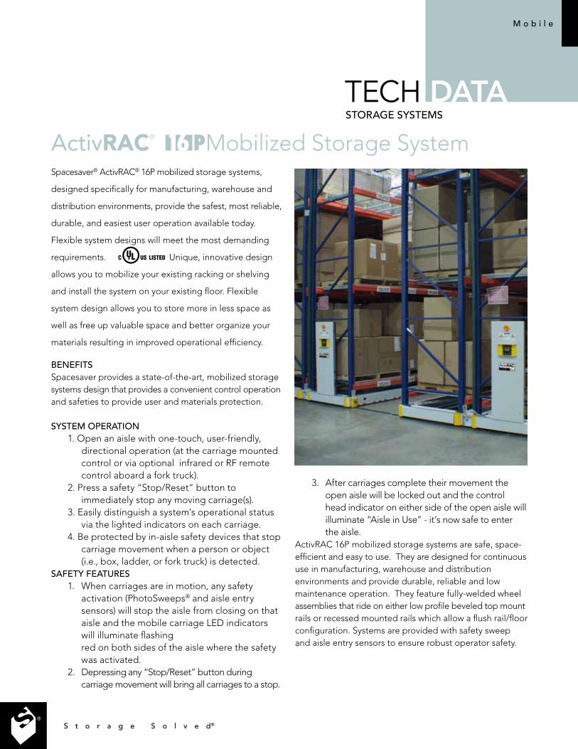
Spacesaver® ActivRAC® 16P mobilized storage systems,
designed specifically for manufacturing, warehouse and
distribution environments, provide the safest, most reliable,
durable, and easiest user operation available today.
Flexible system designs will meet the most demanding
requirements. Unique, innovative design
allows you to mobilize your existing racking or shelving
and install the system on your existing floor. Flexible
system design allows you to store more in less space as
well as free up valuable space and better organize your
materials resulting in improved operational efficiency.
BENEFITSSpacesaver provides a state-of-the-art, mobilized storage systems design that provides a convenient control operation and safeties to provide user and materials protection.
SYSTEM OPERATION1. Open an aisle with one-touch, user-friendly,
directional operation (at the carriage mountedcontrol or via optional infrared or RF remotecontrol aboard a fork truck).
2. Press a safety “Stop/Reset” button toimmediately stop any moving carriage(s).
3. Easily distinguish a system’s operational statusvia the lighted indicators on each carriage.
4. Be protected by in-aisle safety devices that stopcarriage movement when a person or object(i.e., box, ladder, or fork truck) is detected.
SAFETY FEATURES1. When carriages are in motion, any safety
activation (PhotoSweeps® and aisle entrysensors) will stop the aisle from closing on thataisle and the mobile carriage LED indicatorswill illuminate flashingred on both sides of the aisle where the safetywas activated.
2. Depressing any “Stop/Reset” button duringcarriage movement will bring all carriages to a stop.
ActivRAC® Mobilized Storage System
3. After carriages complete their movement theopen aisle will be locked out and the controlhead indicator on either side of the open aisle willilluminate “Aisle in Use” - it’s now safe to enterthe aisle.
ActivRAC 16P mobilized storage systems are safe, space-efficient and easy to use. They are designed for continuous use in manufacturing, warehouse and distribution environments and provide durable, reliable and low maintenance operation. They feature fully-welded wheel assemblies that ride on either low profile beveled top mount rails or recessed mounted rails which allow a flush rail/floor configuration. Systems are provided with safety sweep and aisle entry sensors to ensure robust operator safety.
M o b i l e
TECH DATASTORAgE SYSTEMS
S t o r a g e S o l v e d®
DESIGN AND CAPABILITYA. Powered Systems
• Carriagedesigncapabilitypermitsvirtuallyunlimitedcarriage layout configurations.
• Soft-startcarriagemovementreducessystemstart-upamperage draw and eliminates jostling of stored material during movement.
• PositivedirectwheelDCmotordrivewithsoftstart/stop,dynamic braking, current limiting and automatic time out.
– Provides smooth, even carriage movement. – Protects material stored. – Provides longer system life.
• Infrareddistancesensorsforpreciseprogrammablecarriage positioning.
• toassureelectricalsafety.• Optionaldualcontrolsforaccessingasystemmodule
from both the front and rear.B. Top Mount Rail Design Option All rails are installed on top of concrete slab.
• 3/8”(9.5mm)tallx4-1/2”(114mm)widesteelrailswithblack zinc finish, with beveled edges. ADA compliant.
• Railandcarriagedesignallowsconcreteslabtobeunlevel at the following maximum variation
–3/16”(4.8mm)variationoverany2’(.6m)railrun – 1/4”(6.4mm) maximum variation over any 10’ (3.04m) rail
run• Providesminimalinterruptionofmaterialhandling
equipment • Solid,topmountedonfloor,supportingupto16,000lbs
(7,257kg)perwheelassembly.• Dispersesheavywheelpointloadstofloor.• Designedtooperateunderheavy,long-term,cyclicstress
loads.• Providesthesolidbasicfoundationrequiredforheavy-duty
mobilized storage systems assuring low maintenance and easy operation.
• Staggerrailjointsacrossadjacentrailruns.C. Recessed Rail Design Option All rails are installed flush with concrete slab.
• 3/8”(9.5mm)tallx4”(101.6mm)widesteelrailswithblackzinc finish, designed to be installed flush into the concrete floor.
• Railandcarriagedesignallowsconcreteslabtobeunlevel at the following maximum variation
–3/16”(4.8mm)variationoverany2’(.6m)railrun – 1/4”(6.4mm) maximum variation over any 10’ ( 3.04m) rail run
• Providesflushnon-interruptedtransitionformaterialhandling equipment.
• Solid,flushmountedinfloor,supportingupto16,000lbs(7,257kg)perwheelassembly.
• Dispersesheavywheelpointloadstofloor.• Designedtooperateunderheavy,long-term,cyclicstress
loads.• Providesthesolidbasicfoundationrequiredforheavy-duty
mobilized storage systems assuring low maintenance and easy operation.
• Staggerrailandloaddistributionjointswitheachrailrun.• Staggerrailjointsacrossadjacentrailruns.
D. Wheels• 6”(152mm)DiameterLoadandDriveWheels
• Precisionmachinedsolidsteelwheels. – Provide easy movement. – Prevent premature wear. – Roll easier than smaller wheels.E. Carriage Base/Rack Flue Spacer Articulation (Back to Back Racking Configuration)
• Enablessystemtobeinstalledontypicalexistingconcretefloors without the need for leveled rails, footings, or second floor installation
• Allowssystemtotrackandtransfertherackloadingequally to all carriage wheels.
F. Uniframe Wheel Assemblies & Carriage Base
• Fullyweldeduniframewheelassemblies. – Provides maximum strength for the load and cyclic stress requirements of a mobile system. – One-piece construction assures wheel alignment.
• Assembledstructuralsteelcarriagebasehasamaximumcapacityof16,000lbs(7,257kg)persingleor32,000lbs(14,514kg)back-to-backracksection.
G. Multiple Synchronized Motors• Numberofmotorsvarieswithload,thereby,providingthe
most cost effective design.• Providessmooth,evencarriagemovement.• Maintainspropercarriagealignmentthroughclosed
loop motor feedback and control on all individual motors within carriage regardless of length or weight load distribution. Eliminates racking and binding without the use of tubular or solid steel drive shaft systems.
H. Cross Bracing• Keepswheelassembliesinexactalignment.• Providesrigidbaseforrackingorshelving.
I. Photo Sweep®
• Extendstheentirelengthofbothsidesofthecarriage,stopping movement and slightly backing carriage away when an obstruction is detected.
• Oneinvisiblelightbeampositionedatbottomedgeofeverycarriage provides added safety.
• StandardonallActivRAC16Pmobilizedstoragesystems.J. Aisle Entry Sensor
• Automaticallystopsorpreventscarriagemovementwhena user enters an aisle.
• Shouldauserenteraclosingaisle,thesystemwillstopall carriage movement and that aisle will need to be reset to resume operation.
• Manualresetattheopenedaisleprovidesadditionalsafety by prompting users to visually check the open aisle before resetting the system.
• Solidstatecircuitryandphotoelectrictechnologyensureslong term system reliability.
• StandardonallActivRAC16Pmobilizedstoragesystems.K. Beacon & Horn
• Flashingbeaconwarnsofcarriagemovement.• Hornwarnsofcarriagemovementinareaswhere
beacon cannot be seen.L. Covered Wiring Raceway
• Protectswiringfromabuseandcontamination.M. Overhead Buss Bar Power Distribution System
• Accessaislecanbeaslargeasneeded.• Keepsaislefreefromwiringobstructions.
N. Programmable Features. (Optional)• Systemhasoptionalprogrammablefunctions.(*Interface
TECH DATA P o w e r e d S y s t e m O p e r a t i o n s
from building management or security system will be required by customer)
– System Priority Aisle – System Close Park – System Closed/Night Park* – System Fire Park*Note: Parks and Auto-moves can also be triggered based on time of day and day of week.O. Infrared Remote. (Optional)
• Enablesoperatoronaforktrucktooperateasystemcontrol head within close proximity of the control head without the need to get off the truck.
• ControlsMoveLeft,MoveRight,Stop/Resetwhendirectedat the control head and at the needed activation location.
P. Radio Frequency Remote. (Optional)• Enablesoperatoronaforktrucktoopenanaisleremotely
from up to 1000’ with no building or large equipment obstructions,orupto350’withobstructions.
• Systemmustalsohaveaisleentrysensorsandusedinconjunction with the infrared remote so that the system must be in a clear or ready green state to activate the aisle with the RFremoteremotely.Ifthesystemisinuse,theRFRemotewill not remotely open any requested aisle in the system.
• AsingleRFremoteiscapableofcontrollinguptosix(6)carriagesinasinglemoduleanduptofifteen(15)modules
from a single remote. Q. Power Override Unit. (Optional)
• Handheldrechargeablebatteryunitenablesasinglecarriage to be moved at a reduced speed if a power failure was to occur and the system needed to be accessed.
R. Touch Pad Control (Optional)• Canbeutilizedtoaccessasystemmoduleorspecific
aisles• Featurespinaccesswithaudittrailcapability• Cantrackwhoandwhensystemoraisleisaccessed• Canlimitaccesstospecificaislesbyuser
S. Computer Interface (Optional)
• ComputerinterfaceallowsaisleselectionviaPC.(InterfacetoWMSorERPsystemprovidedbycustomer).
T. Seismic Articulation Joint SAJ (Optional)• Designedtostructurallycouplepiggy-backracking
uprights together during excessive ground movement often caused by an earthquake
• Allowsthemobilecarriagestofreelyarticulatewhenoperating normally over unleveled rail
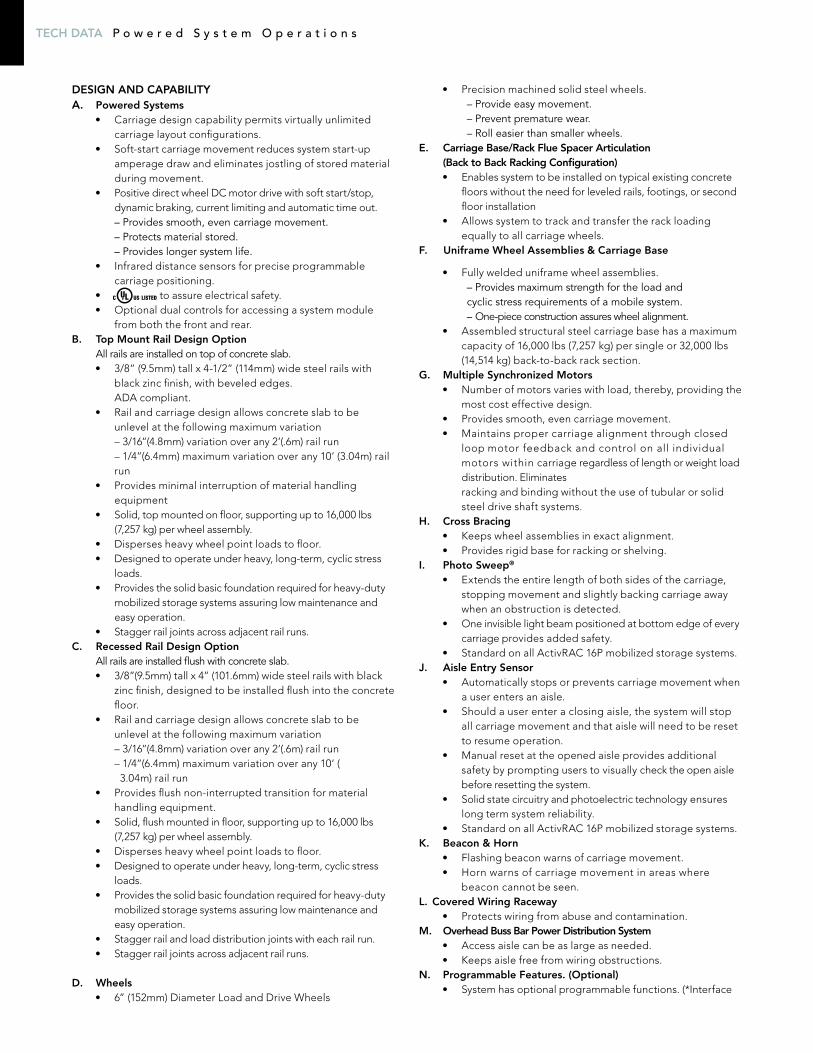
M PO Q T
F
CB
G
H
D
I
J A
KR
E
M o b i l e
RAIl- TOP MOUNT:Railshallbe,4140steelbar41/2”(114mm)widex3/8”(9.5mm)highwithblackzincfinish.Railedgesshallbebeveleddowntoamaximumof3/16”(4.8mm)toallowfortherailtobe transversed by material handling equipment. Rail shall disperse the wheel point loads to structural slab. Rail shall havetwopermanentlymountedflooranchorsmaximum15”(381mm)oncenter.Railsshallbeinstalledontopofconcreteslab. Rail and carriage design allows concrete slab to be unlevelatthefollowingmaximumvariationof3/16”(4.8mm)variation over any 2’ (0.6m) rail run and 1/4” (6.4mm) maximum variation over any 10’ (3.04m) rail run.
Rail-ReCessedMount:Railshallbe,4140steelbar4”(101.6mm)widex3/8”(9.5mm)highwithblackzincfinish.Railshalldispersethewheel point loads to structural slab. Rail shall have two permanentlymountedflooranchorsmaximum15”(381mm)on center. Rail shall be installed recessed into concrete slab and flush to top of concrete slab. Rail and carriage design allows concrete slab to be unlevel at the following maximum variationof3/16”(4.8mm)variationoverany2’(0.6m)railrunand 1/4” (6.4mm) maximum variation over any 10’ (3.04m) rail run.
MobileCaRRiagebases:Assembled structural steel carriage base will have a minumum capacityof16,000lbs.(7,257kg)persingleand32,000lbs.(14,514kg)perback-to-backracksection.Onback-to-back configurations, individual wheel assemblies must be connected with an articulated carriage base/rack flue spacers in order to have the system track and transfer the rack loading equally to all carriage wheels. Each wheel assembly shall be equipped withtwowheels,minimum6”(152mm)diametersteelwheels.Wheels are equipped with two permanently lubricated andshieldedradialballbearings.Wheelcapacity8,000lbs(3,628kg)each.Wheelshavesolidsteelaxlesof1-3/8”in(35mm)diameter.Wheelsshallbedualflange,allwheelguided. All carriage sections between wheel assemblies have integral cross bracing to maintain accepted tolerances for function of systems. Side profiles shall provide and maintain wheel assembly alignment and squareness. These profiles shall be pre-drilled at the factory but are bolted, and assembled on the job site as integral carriage members.
Wiring shall be routed through an enclosed housing channel to protect the electronic wiring harness. Structural steel side profilesshallbeminimum6.165”(157mm)high,8gauge(4.2mm). Finish shall be powder coat paint. Structural bases shallbeplacedbacktobackwithminimum6”(152mm)clearflue between back-to-back carriages.
PoweR&ContRols:System power requirements - 120 VAC single phase input. Poweredcarriagesshallbeequippedwith¼HP;90-voltDC gear motors. Multiple carriages shall be moved with a single activation of a carriage control and/or via an infrared or RF remote. Each carriage shall be equipped with one ormore¼HP,90-voltDCgearmotors,dependingonloadrating. Each independent drive shall be synchronous and current limiting to maintain proper alignment through closed loop motor feedback and control on all individual motors within the carriage regardless of length or weight load and eliminate racking and binding. Motor and motor control-lers shall provide for soft-start/soft-stop movement, current limiting, and automatic time-out. Carriage movement to be selectable between sequential to minimize power demands on start-up, or block movement for faster access Motors and power train shall provide for maximum carriage travel speed of 3” (76mm) per second. All power transfer to wheels to be done by chain drive. Power to mobile units provided by an overhead buss bar system. Communication between carriages is provided by overhead cable festoon. Power supply to be provided by others.
SAFETY FEATURES:The following safety features are to be provided: Photoelectric safety sweep scanning the full length of both sides of each carriage. The sweep will prevent or immediately stop move-ment if an obstruction is encountered or the beam is broken. Photoelectric aisle entry sensor shall be positioned at each entry location. The aisle entry beam will prevent or imme-diately stop movement if an obstruction is encountered or the beam is broken. Status of the safeties to be displayed on the control unit. Stop pushbutton shall be provided at each aisle control. A warning horn shall be provided whereupon activation of an aisle movement pushbutton it will sound for the first 3 seconds of carriage movement. A flashing yellow warning light is provided on the carriage ends that will flash during system movement.
Specifications are subject to changePatent Pending
SpacesaverCorporationisadivisionofKI.
KIandSpacesaverareregisteredtrademarksofKruegerInternational,Inc.
©2013KIandSpacesaverCorporation.AllRightsReserved.LithoinUSA.SSC/MRKActivRAC16P_0213_Tech(Actvrc16P-TD)
teChniCalsPeCifiCations
TECH DATA P o w e r e d S y s t e m O p e r a t i o n s
Bradford Systems Corporate Offices430 Country Club Drive Bensenville, Illinois 60106 1-800-696-3453