Embed Size (px)
Citation preview
TECE FLUSHING TECHNOLOGY
Sanitary systems
TECHNICAL GUIDELINES

Flus
hing
tech
nolo
gy
6-2
Flus
hing
tech
nolo
gy
6-3
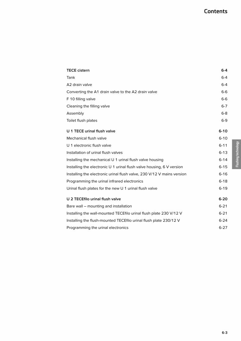
TECE cistern 6-4
Tank 6-4
A2 drain valve 6-4
Converting the A1 drain valve to the A2 drain valve 6-6
F 10 filling valve 6-6
Cleaning the filling valve 6-7
Assembly 6-8
Toilet flush plates 6-9
U 1 TECE urinal flush valve 6-10
Mechanical flush valve 6-10
U 1 electronic flush valve 6-11
Installation of urinal flush valves 6-13
Installing the mechanical U 1 urinal flush valve housing 6-14
Installing the electronic U 1 urinal flush valve housing, 6 V version 6-15
Installing the electronic urinal flush valve, 230 V/12 V mains version 6-16
Programming the urinal infrared electronics 6-18
Urinal flush plates for the new U 1 urinal flush valve 6-19
U 2 TECEfilo urinal flush valve 6-20
Bare wall – mounting and installation 6-21
Installing the wall-mounted TECEfilo urinal flush plate 230 V/12 V 6-21
Installing the flush-mounted TECEfilo urinal flush plate 230/12 V 6-24
Programming the urinal electronics 6-27
Contents
Flus
hing
tech
nolo
gy
6-4
TECE flushing technology – cistern
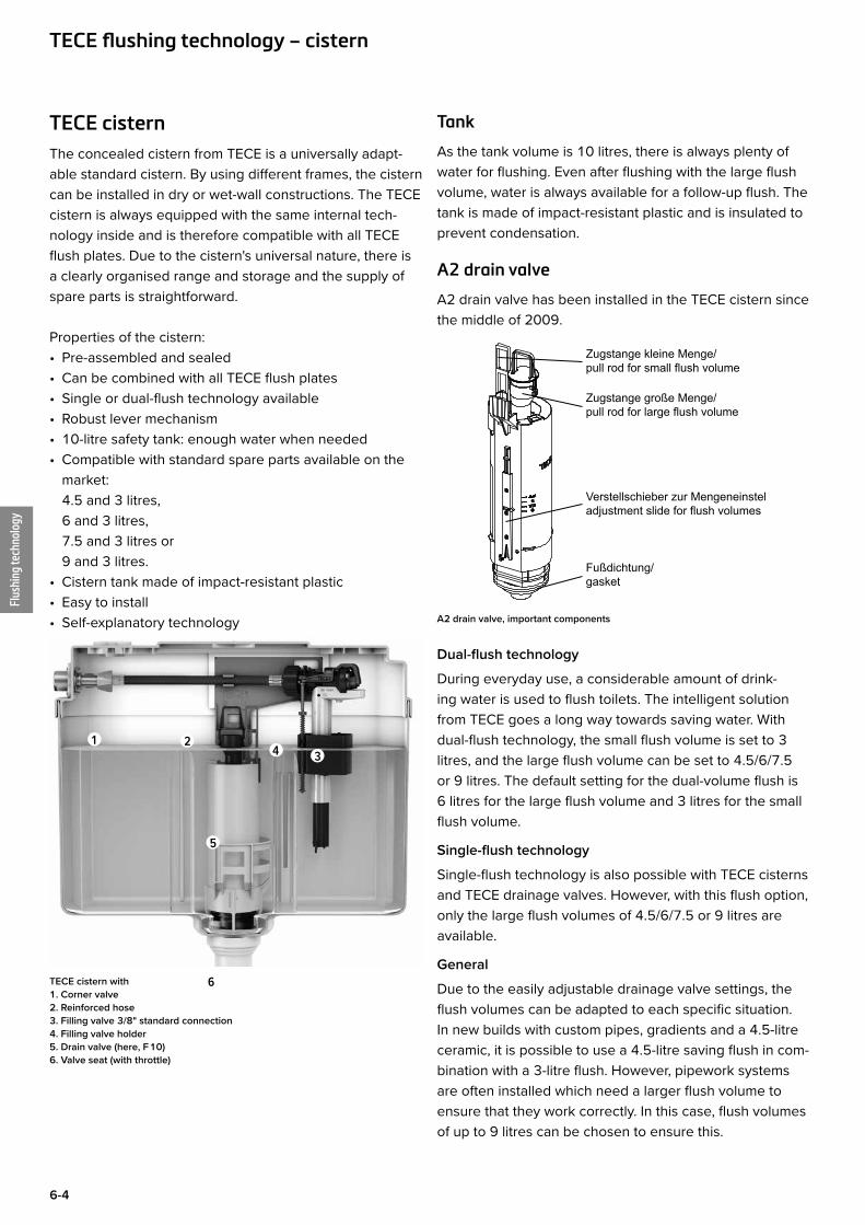
TECE cisternThe concealed cistern from TECE is a universally adapt-able standard cistern. By using different frames, the cistern can be installed in dry or wet-wall constructions. The TECE cistern is always equipped with the same internal tech-nology inside and is therefore compatible with all TECE flush plates. Due to the cistern's universal nature, there is a clearly organised range and storage and the supply of spare parts is straightforward.
Properties of the cistern:• Pre-assembled and sealed• Can be combined with all TECE flush plates• Single or dual-flush technology available• Robust lever mechanism• 10-litre safety tank: enough water when needed• Compatible with standard spare parts available on the
market: 4.5 and 3 litres, 6 and 3 litres, 7.5 and 3 litres or 9 and 3 litres.
• Cistern tank made of impact-resistant plastic• Easy to install• Self-explanatory technology
TECE cistern with 1. Corner valve 2. Reinforced hose 3. Filling valve 3/8" standard connection 4. Filling valve holder 5. Drain valve (here, F 10) 6. Valve seat (with throttle)
Tank
As the tank volume is 10 litres, there is always plenty of water for flushing. Even after flushing with the large flush volume, water is always available for a follow-up flush. The tank is made of impact-resistant plastic and is insulated to prevent condensation.
A2 drain valve
A2 drain valve has been installed in the TECE cistern since the middle of 2009.
Zugstange kleine Menge/pull rod for small flush volume
Zugstange große Menge/pull rod for large flush volume
Verstellschieber zur Mengeneinstellung/adjustment slide for flush volumes
Fußdichtung/gasket
A2 drain valve, important components
Dual-flush technology
During everyday use, a considerable amount of drink-ing water is used to flush toilets. The intelligent solution from TECE goes a long way towards saving water. With dual-flush technology, the small flush volume is set to 3 litres, and the large flush volume can be set to 4.5/6/7.5 or 9 litres. The default setting for the dual-volume flush is 6 litres for the large flush volume and 3 litres for the small flush volume.
Single-flush technology
Single-flush technology is also possible with TECE cisterns and TECE drainage valves. However, with this flush option, only the large flush volumes of 4.5/6/7.5 or 9 litres are available.
General
Due to the easily adjustable drainage valve settings, the flush volumes can be adapted to each specific situation. In new builds with custom pipes, gradients and a 4.5-litre ceramic, it is possible to use a 4.5-litre saving flush in com-bination with a 3-litre flush. However, pipework systems are often installed which need a larger flush volume to ensure that they work correctly. In this case, flush volumes of up to 9 litres can be chosen to ensure this.
1 23
6
5
4
Flus
hing
tech
nolo
gy
6-5
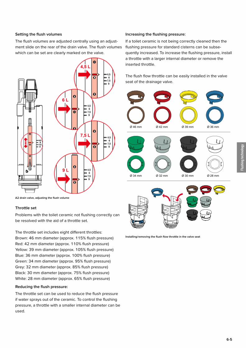
Setting the flush volumes
The flush volumes are adjusted centrally using an adjust-ment slide on the rear of the drain valve. The flush volumes which can be set are clearly marked on the valve.
A2 drain valve, adjusting the flush volume
Throttle set
Problems with the toilet ceramic not flushing correctly can be resolved with the aid of a throttle set.
The throttle set includes eight different throttles:Brown: 46 mm diameter (approx. 115% flush pressure)Red: 42 mm diameter (approx. 110% flush pressure)Yellow: 39 mm diameter (approx. 105% flush pressure)Blue: 36 mm diameter (approx. 100% flush pressure)Green: 34 mm diameter (approx. 95% flush pressure)Grey: 32 mm diameter (approx. 85% flush pressure)Black: 30 mm diameter (approx. 75% flush pressure)White: 28 mm diameter (approx. 65% flush pressure)
Reducing the flush pressure:
The throttle set can be used to reduce the flush pressure if water sprays out of the ceramic. To control the flushing pressure, a throttle with a smaller internal diameter can be used.
Increasing the flushing pressure:
If a toilet ceramic is not being correctly cleaned then the flushing pressure for standard cisterns can be subse-quently increased. To increase the flushing pressure, install a throttle with a larger internal diameter or remove the inserted throttle.
The flush flow throttle can be easily installed in the valve seat of the drainage valve.
Ø 36 mmØ 39 mmØ 42 mmØ 46 mm
Ø 28 mmØ 30 mmØ 32 mmØ 34 mm
Installing/removing the flush flow throttle in the valve seat
Flus
hing
tech
nolo
gy
6-6
TECE flushing technology – cistern
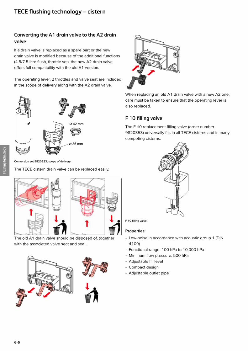
Converting the A1 drain valve to the A2 drain valve
If a drain valve is replaced as a spare part or the new drain valve is modified because of the additional functions (4.5/7.5 litre flush, throttle set), the new A2 drain valve offers full compatibility with the old A1 version.
The operating lever, 2 throttles and valve seat are included in the scope of delivery along with the A2 drain valve.
36 mm
42 mm
Conversion set 9820223, scope of delivery
The TECE cistern drain valve can be replaced easily.
The old A1 drain valve should be disposed of, together with the associated valve seat and seal.
When replacing an old A1 drain valve with a new A2 one, care must be taken to ensure that the operating lever is also replaced.
F 10 filling valve
The F 10 replacement filling valve (order number 9820353) universally fits in all TECE cisterns and in many competing cisterns.
F 10 filling valve
Properties:
• Low-noise in accordance with acoustic group 1 (DIN 4109)
• Functional range: 100 hPa to 10,000 hPa• Minimum flow pressure: 500 hPa• Adjustable fill level• Compact design• Adjustable outlet pipe
Flus
hing
tech
nolo
gy
6-7
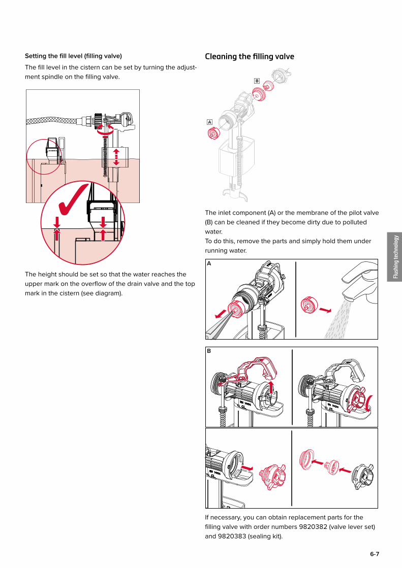
Setting the fill level (filling valve)
The fill level in the cistern can be set by turning the adjust-ment spindle on the filling valve.
The height should be set so that the water reaches the upper mark on the overflow of the drain valve and the top mark in the cistern (see diagram).
Cleaning the filling valve
A
B
The inlet component (A) or the membrane of the pilot valve (B) can be cleaned if they become dirty due to polluted water.To do this, remove the parts and simply hold them under running water.
If necessary, you can obtain replacement parts for the filling valve with order numbers 9820382 (valve lever set) and 9820383 (sealing kit).
A
B
Flus
hing
tech
nolo
gy
6-8
TECE flushing technology – cistern
Assembly
Shell construction stage
The corner valve of the TECE concealed cistern is closed and pre-installed as a complete unit. The pressure can be tested without the cistern needing to be opened. The cistern only needs to be opened during the fine installa-tion phase. During the shell construction stage, the cistern remains sealed. An unbroken seal during fine installation work guarantees that the cistern is clean and functional. A damaged seal shows that the cistern has already been opened.
Splash protection with seal
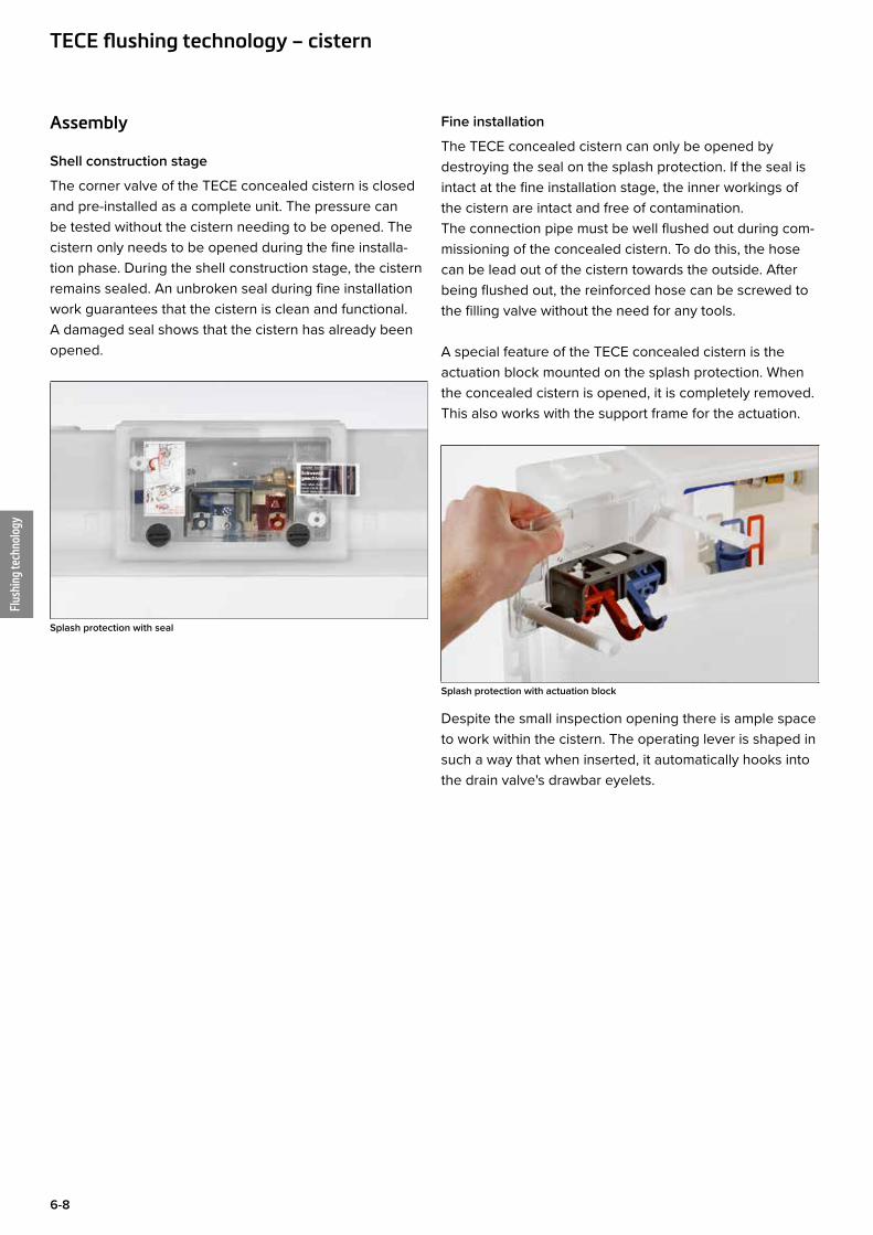
Fine installation
The TECE concealed cistern can only be opened by destroying the seal on the splash protection. If the seal is intact at the fine installation stage, the inner workings of the cistern are intact and free of contamination. The connection pipe must be well flushed out during com-missioning of the concealed cistern. To do this, the hose can be lead out of the cistern towards the outside. After being flushed out, the reinforced hose can be screwed to the filling valve without the need for any tools.
A special feature of the TECE concealed cistern is the actuation block mounted on the splash protection. When the concealed cistern is opened, it is completely removed. This also works with the support frame for the actuation.
Splash protection with actuation block
Despite the small inspection opening there is ample space to work within the cistern. The operating lever is shaped in such a way that when inserted, it automatically hooks into the drain valve's drawbar eyelets.
Flus
hing
tech
nolo
gy
6-9
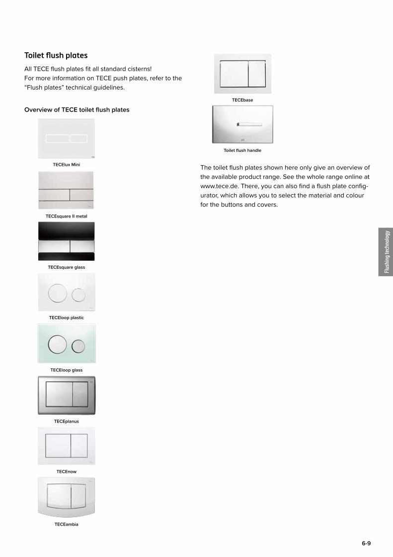
Toilet flush plates
All TECE flush plates fit all standard cisterns! For more information on TECE push plates, refer to the “Flush plates” technical guidelines.
Overview of TECE toilet flush plates
TECElux Mini
TECEsquare II metal
TECEsquare glass
TECEloop plastic
TECEloop glass
TECEplanus
TECEnow
TECEambia
TECEbase
Toilet flush handle
The toilet flush plates shown here only give an overview of the available product range. See the whole range online at www.tece.de. There, you can also find a flush plate config-urator, which allows you to select the material and colour for the buttons and covers.

Flus
hing
tech
nolo
gy
6-10
TECE flushing technology – U 1 urinal flush valve
U 1 TECE urinal flush valve The TECE U 1 urinal flush valve is based on a further development of tried and tested flush valve technology. Well-conceived details and improved materials ensure a long life and high reliability.
The TECE urinal flush valve is suitable for mechanical and electronic actuation. The same housing is used in both cases. The flush volume can be set from one to a maxi-mum of about eight litres.
+
mechanical cartridge
or
electronic cartridge
Housing for urinal flush valve and cartridges
Manual and electronic cartridges have the same flush valve housing and the same high flush performance of > 0.3 l/s at 1 bar. Using the following flow diagram, you can calculate the flush volume for the urinal pressure flushing system depending on mains pressure and flush time.
Durchfluss / flow in [l/s]
Dru
ck /
pres
sure
in [b
ar]
0 0,1 0,2 0,3 0,4 0,5 0,6 0,7 0,8 0,90
1
2
3
4
5
6
0,58
Flow diagram of urinal electronics
Example: Mains pressure 3 bar: Flushing flow = 0.58 l/sFlush time e.g. 3.5 s: Flush volume approx: 2 litres
The flush housing contains the inlet flow control, this is adjusted using an Allen key (3 mm). A 90° anti-clockwise turn closes the inlet flow control, a 90° clockwise turn opens it.
Vorabsperrung / inlet flow control
“auf / open” “zu / close”
Inlet flow control
Mechanical flush valve
The mechanical flush valve (to DIN EN 12541) is hydrau-lically controlled and is sturdy and reliable. An automatic jet cleaning function ensures long and maintenance-free operation. The adjustable flush volume remains constant, irrespective of the supply pressure.
Mechanical cartridge
Volume adjustment
The flush volume of the mechanical cartridge can be set to 1, 2 or 4 litres using a retaining ring. When the retaining ring is removed, the flusher can be set to 6 – 8 litres.
Flus
hing
tech
nolo
gy
6-11
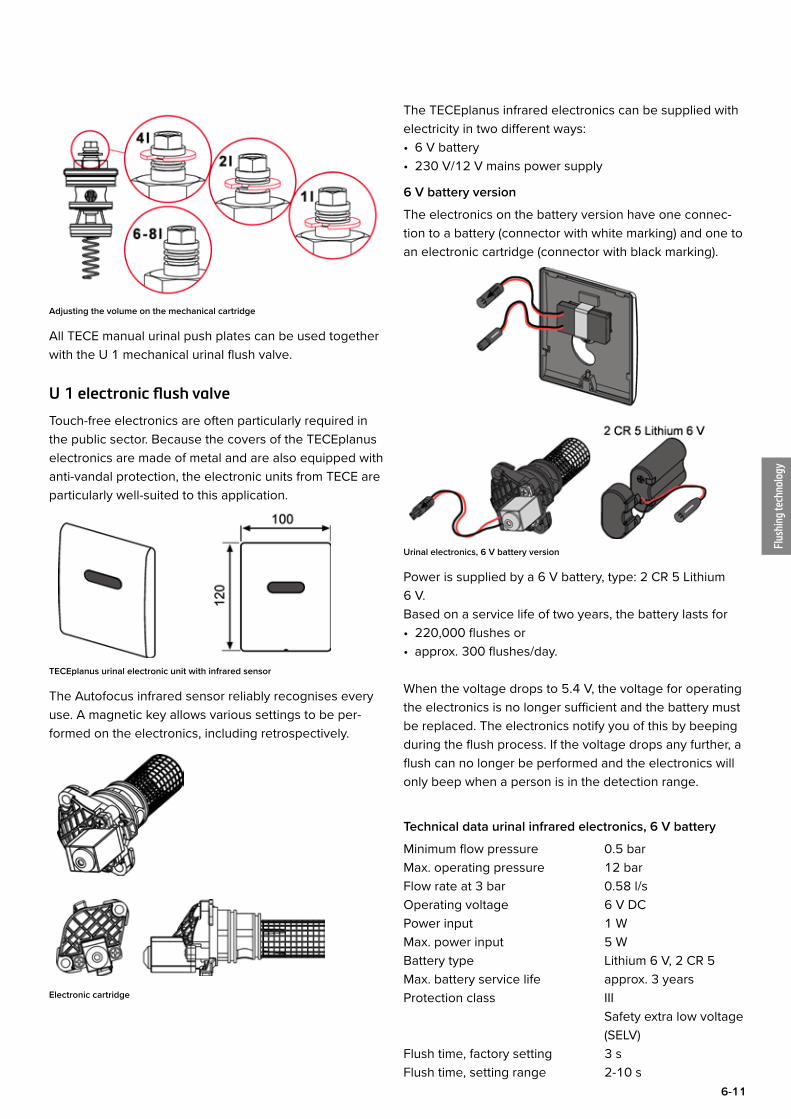
Adjusting the volume on the mechanical cartridge
All TECE manual urinal push plates can be used together with the U 1 mechanical urinal flush valve.
U 1 electronic flush valve
Touch-free electronics are often particularly required in the public sector. Because the covers of the TECEplanus electronics are made of metal and are also equipped with anti-vandal protection, the electronic units from TECE are particularly well-suited to this application.
TECEplanus urinal electronic unit with infrared sensor
The Autofocus infrared sensor reliably recognises every use. A magnetic key allows various settings to be per-formed on the electronics, including retrospectively.
Electronic cartridge
The TECEplanus infrared electronics can be supplied with electricity in two different ways:• 6 V battery• 230 V/12 V mains power supply
6 V battery version
The electronics on the battery version have one connec-tion to a battery (connector with white marking) and one to an electronic cartridge (connector with black marking).
Urinal electronics, 6 V battery version
Power is supplied by a 6 V battery, type: 2 CR 5 Lithium 6 V. Based on a service life of two years, the battery lasts for• 220,000 flushes or• approx. 300 flushes/day.
When the voltage drops to 5.4 V, the voltage for operating the electronics is no longer sufficient and the battery must be replaced. The electronics notify you of this by beeping during the flush process. If the voltage drops any further, a flush can no longer be performed and the electronics will only beep when a person is in the detection range.
Technical data urinal infrared electronics, 6 V battery
Minimum flow pressure 0.5 barMax. operating pressure 12 barFlow rate at 3 bar 0.58 l/sOperating voltage 6 V DCPower input 1 WMax. power input 5 WBattery type Lithium 6 V, 2 CR 5Max. battery service life approx. 3 yearsProtection class III Safety extra low voltage (SELV)Flush time, factory setting 3 sFlush time, setting range 2-10 s
Flus
hing
tech
nolo
gy
6-12
TECE flushing technology – U 1 urinal flush valve
Pre-flush, factory setting offPre-flush, setting range 0.5-2 sPause function, factory setting offHygiene flush, factory setting offHygiene flush, setting range off, 24 hours, 255 hours
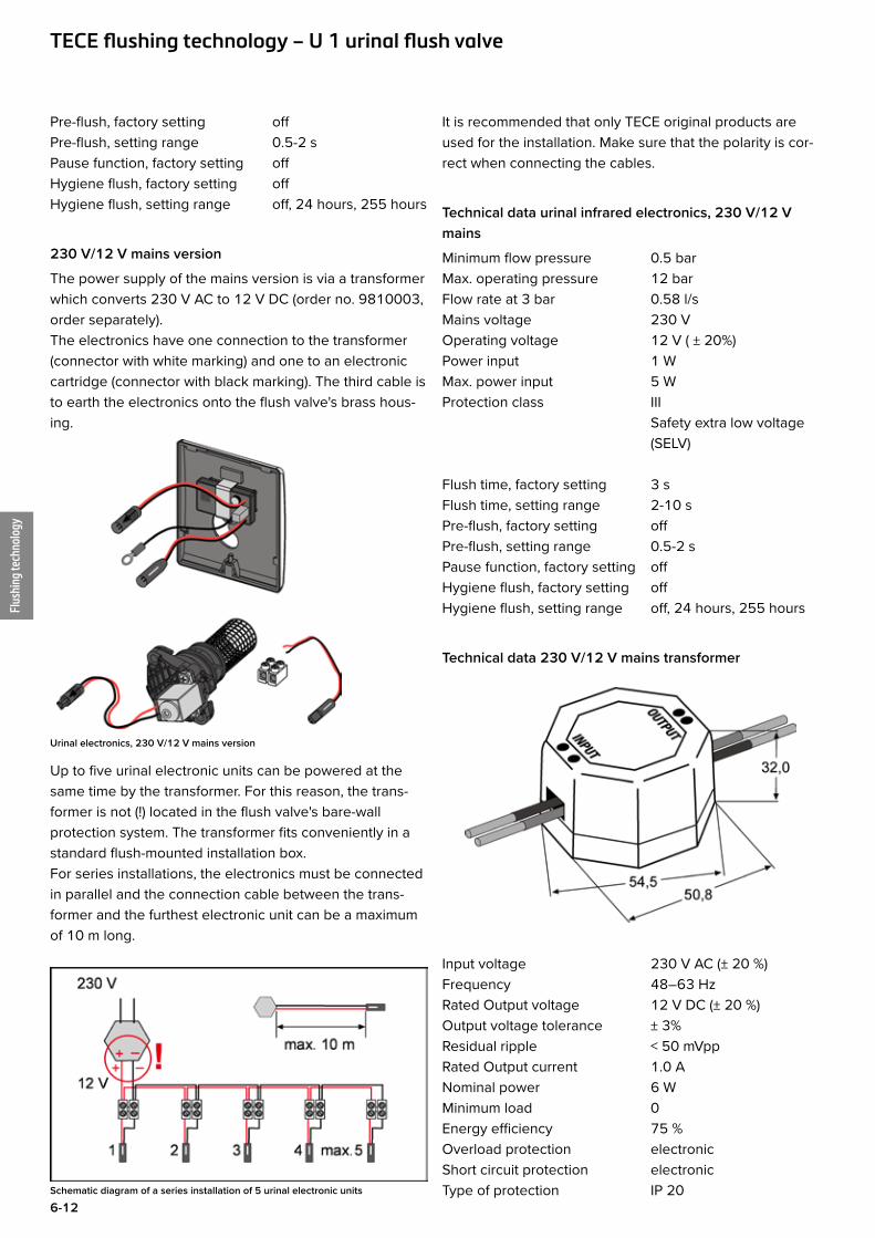
230 V/12 V mains version
The power supply of the mains version is via a transformer which converts 230 V AC to 12 V DC (order no. 9810003, order separately).The electronics have one connection to the transformer (connector with white marking) and one to an electronic cartridge (connector with black marking). The third cable is to earth the electronics onto the flush valve's brass hous-ing.
Urinal electronics, 230 V/12 V mains version
Up to five urinal electronic units can be powered at the same time by the transformer. For this reason, the trans-former is not (!) located in the flush valve's bare-wall protection system. The transformer fits conveniently in a standard flush-mounted installation box.For series installations, the electronics must be connected in parallel and the connection cable between the trans-former and the furthest electronic unit can be a maximum of 10 m long.
Schematic diagram of a series installation of 5 urinal electronic units
It is recommended that only TECE original products are used for the installation. Make sure that the polarity is cor-rect when connecting the cables.
Technical data urinal infrared electronics, 230 V/12 V mains
Minimum flow pressure 0.5 barMax. operating pressure 12 barFlow rate at 3 bar 0.58 l/sMains voltage 230 VOperating voltage 12 V ( ± 20%)Power input 1 WMax. power input 5 WProtection class III Safety extra low voltage (SELV)
Flush time, factory setting 3 sFlush time, setting range 2-10 sPre-flush, factory setting offPre-flush, setting range 0.5-2 sPause function, factory setting offHygiene flush, factory setting offHygiene flush, setting range off, 24 hours, 255 hours
Technical data 230 V/12 V mains transformer
Input voltage 230 V AC (± 20 %) Frequency 48–63 HzRated Output voltage 12 V DC (± 20 %)Output voltage tolerance ± 3%Residual ripple < 50 mVppRated Output current 1.0 ANominal power 6 WMinimum load 0Energy efficiency 75 %Overload protection electronicShort circuit protection electronicType of protection IP 20
Flus
hing
tech
nolo
gy
6-13
Protection class II CE low voltage power supply
Operating temperature - 20 °C to + 40 °CSafety standard EN 61 558/EN 60 950EMV standard EN 55 022/BTechnology SwitchingSwitch frequency 100 KHzDielectric resistance 3 750 V/1 minMTBF (MIL HDBK217) 120, 000 h
Installation of urinal flush valves
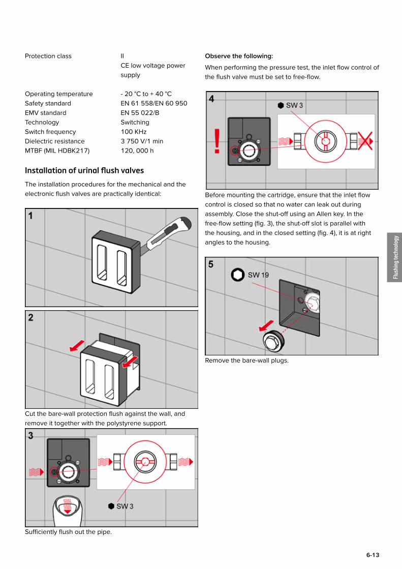
The installation procedures for the mechanical and the electronic flush valves are practically identical:
Cut the bare-wall protection flush against the wall, and remove it together with the polystyrene support.
Sufficiently flush out the pipe.
Observe the following:
When performing the pressure test, the inlet flow control of the flush valve must be set to free-flow.
Before mounting the cartridge, ensure that the inlet flow control is closed so that no water can leak out during assembly. Close the shut-off using an Allen key. In the free-flow setting (fig. 3), the shut-off slot is parallel with the housing, and in the closed setting (fig. 4), it is at right angles to the housing.
Remove the bare-wall plugs.
Flus
hing
tech
nolo
gy
6-14
TECE flushing technology – U 1 urinal flush valve
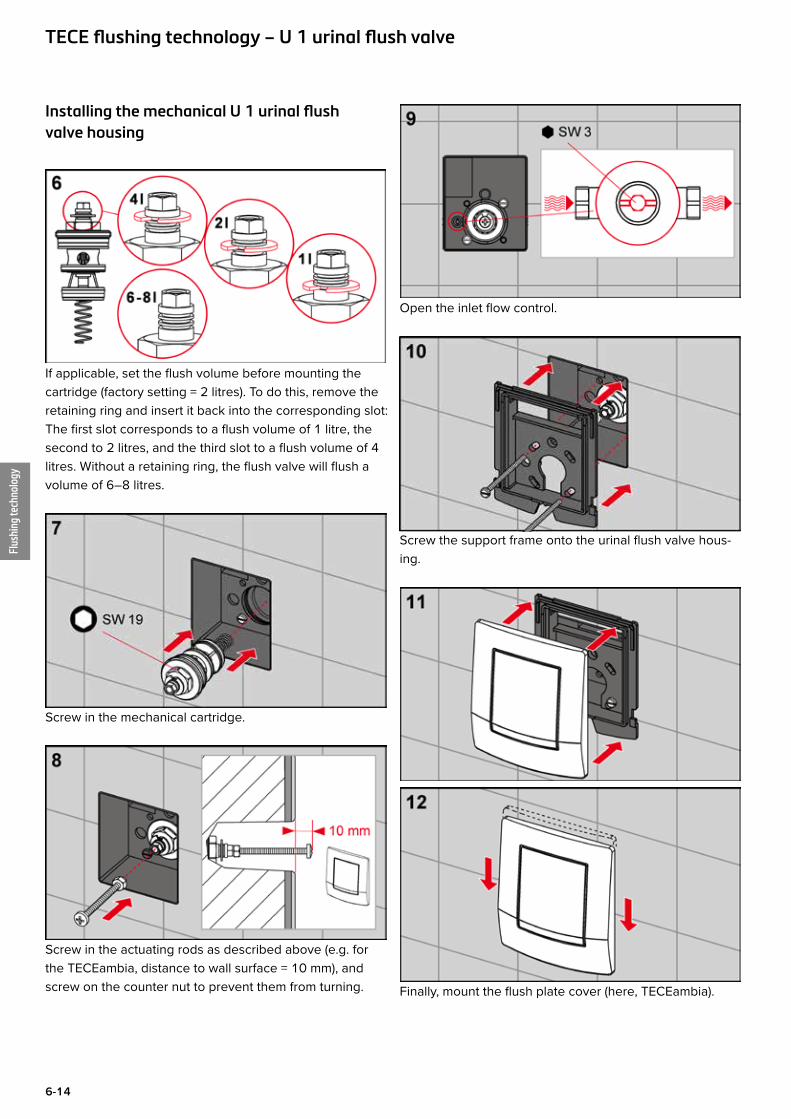
Installing the mechanical U 1 urinal flush valve housing
If applicable, set the flush volume before mounting the cartridge (factory setting = 2 litres). To do this, remove the retaining ring and insert it back into the corresponding slot: The first slot corresponds to a flush volume of 1 litre, the second to 2 litres, and the third slot to a flush volume of 4 litres. Without a retaining ring, the flush valve will flush a volume of 6–8 litres.
Screw in the mechanical cartridge.
Screw in the actuating rods as described above (e.g. for the TECEambia, distance to wall surface = 10 mm), and screw on the counter nut to prevent them from turning.
Open the inlet flow control.
Screw the support frame onto the urinal flush valve hous-ing.
Finally, mount the flush plate cover (here, TECEambia).
Flus
hing
tech
nolo
gy
6-15
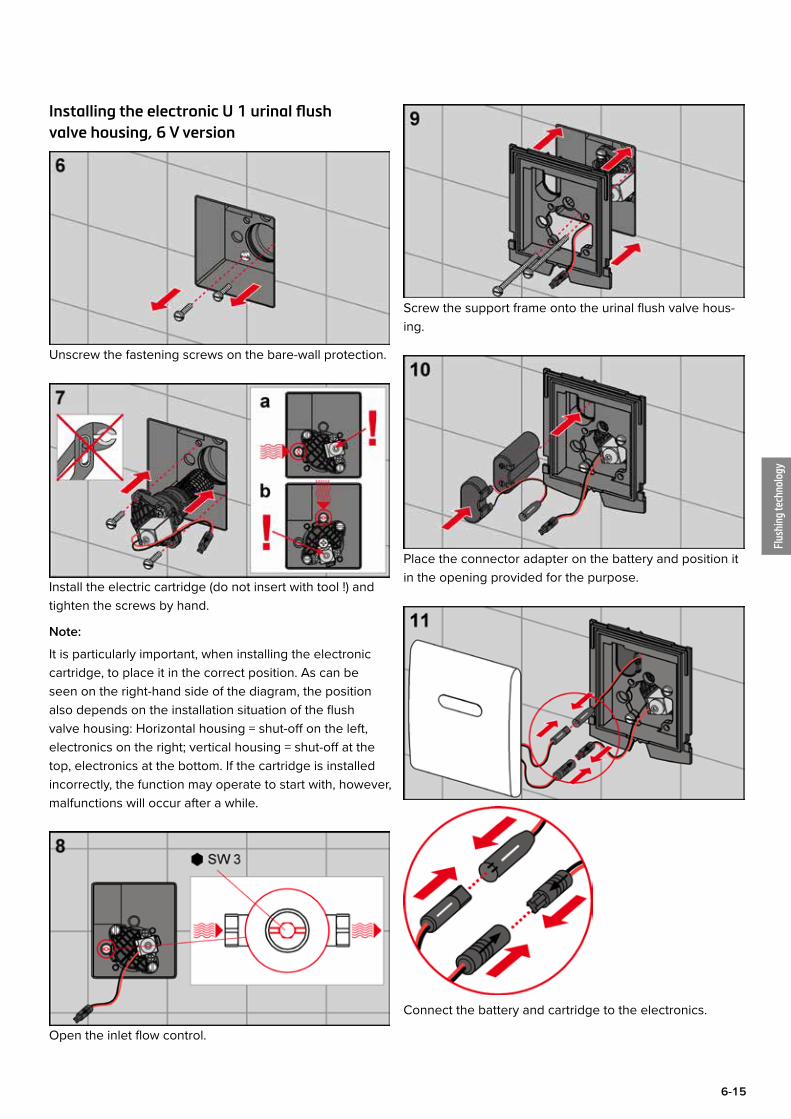
Installing the electronic U 1 urinal flush valve housing, 6 V version
Unscrew the fastening screws on the bare-wall protection.
Install the electric cartridge (do not insert with tool !) and tighten the screws by hand.
Note:
It is particularly important, when installing the electronic cartridge, to place it in the correct position. As can be seen on the right-hand side of the diagram, the position also depends on the installation situation of the flush valve housing: Horizontal housing = shut-off on the left, electronics on the right; vertical housing = shut-off at the top, electronics at the bottom. If the cartridge is installed incorrectly, the function may operate to start with, however, malfunctions will occur after a while.
Open the inlet flow control.
Screw the support frame onto the urinal flush valve hous-ing.
Place the connector adapter on the battery and position it in the opening provided for the purpose.
Connect the battery and cartridge to the electronics.
Flus
hing
tech
nolo
gy
6-16
TECE flushing technology – U 1 urinal flush valve
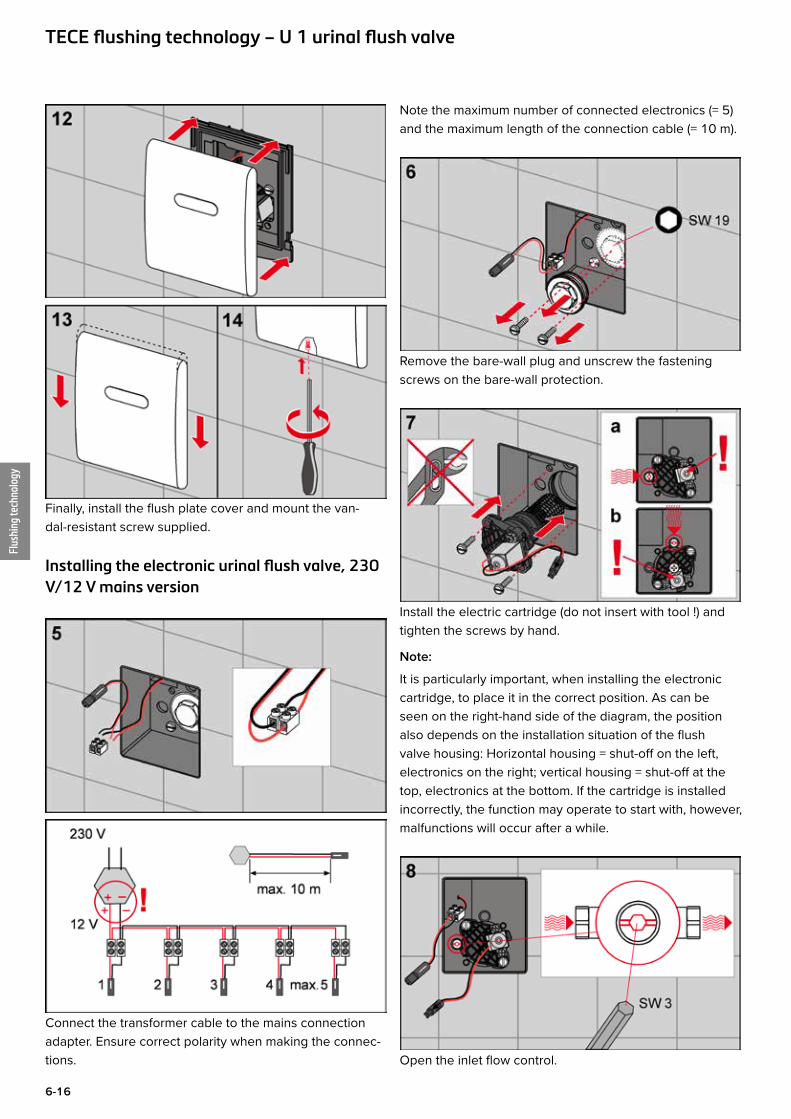
Finally, install the flush plate cover and mount the van-dal-resistant screw supplied.
Installing the electronic urinal flush valve, 230 V/12 V mains version
Connect the transformer cable to the mains connection adapter. Ensure correct polarity when making the connec-tions.
Note the maximum number of connected electronics (= 5) and the maximum length of the connection cable (= 10 m).
Remove the bare-wall plug and unscrew the fastening screws on the bare-wall protection.
Install the electric cartridge (do not insert with tool !) and tighten the screws by hand.
Note:
It is particularly important, when installing the electronic cartridge, to place it in the correct position. As can be seen on the right-hand side of the diagram, the position also depends on the installation situation of the flush valve housing: Horizontal housing = shut-off on the left, electronics on the right; vertical housing = shut-off at the top, electronics at the bottom. If the cartridge is installed incorrectly, the function may operate to start with, however, malfunctions will occur after a while.
Open the inlet flow control.
Flus
hing
tech
nolo
gy
6-17
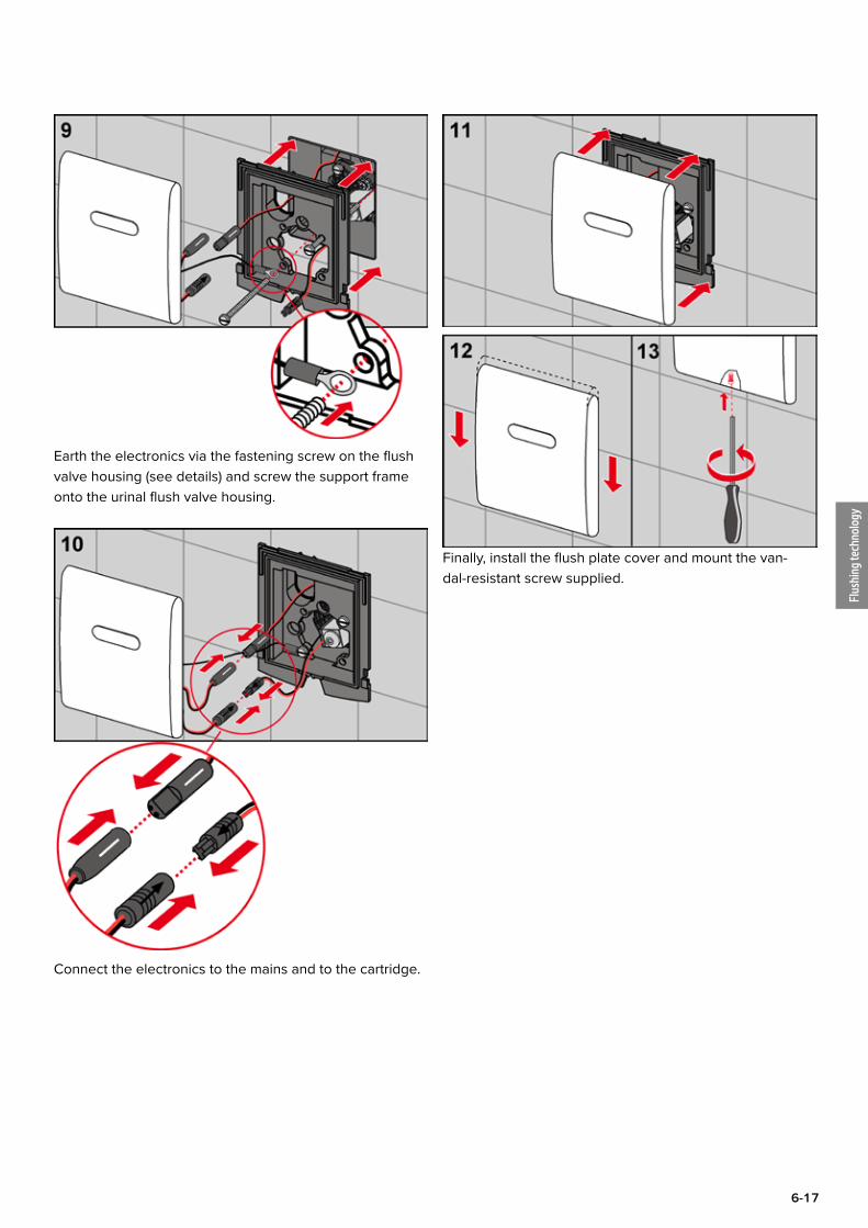
Earth the electronics via the fastening screw on the flush valve housing (see details) and screw the support frame onto the urinal flush valve housing.
Connect the electronics to the mains and to the cartridge.
Finally, install the flush plate cover and mount the van-dal-resistant screw supplied.
Flus
hing
tech
nolo
gy
6-18
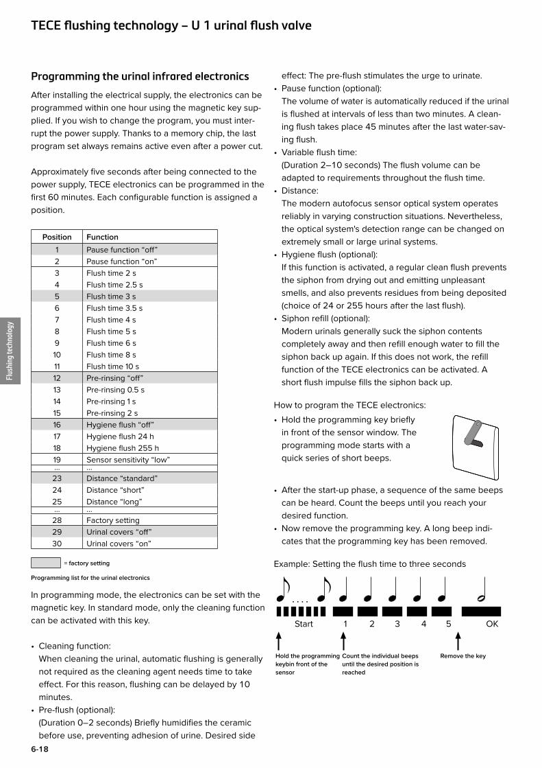
Programming the urinal infrared electronics
After installing the electrical supply, the electronics can be programmed within one hour using the magnetic key sup-plied. If you wish to change the program, you must inter-rupt the power supply. Thanks to a memory chip, the last program set always remains active even after a power cut.
Approximately five seconds after being connected to the power supply, TECE electronics can be programmed in the first 60 minutes. Each configurable function is assigned a position.
Position Function1 Pause function “off”2 Pause function “on”3 Flush time 2 s4 Flush time 2.5 s5 Flush time 3 s6 Flush time 3.5 s7 Flush time 4 s8 Flush time 5 s9 Flush time 6 s10 Flush time 8 s11 Flush time 10 s12 Pre-rinsing “off”13 Pre-rinsing 0.5 s14 Pre-rinsing 1 s15 Pre-rinsing 2 s16 Hygiene flush “off”17 Hygiene flush 24 h18 Hygiene flush 255 h19 Sensor sensitivity “low”... ...23 Distance “standard”24 Distance “short”25 Distance “long”... ...28 Factory setting29 Urinal covers “off”30 Urinal covers “on”
= factory setting
Programming list for the urinal electronics
In programming mode, the electronics can be set with the magnetic key. In standard mode, only the cleaning function can be activated with this key.
• Cleaning function: When cleaning the urinal, automatic flushing is generally not required as the cleaning agent needs time to take effect. For this reason, flushing can be delayed by 10 minutes.
• Pre-flush (optional): (Duration 0–2 seconds) Briefly humidifies the ceramic before use, preventing adhesion of urine. Desired side
effect: The pre-flush stimulates the urge to urinate.• Pause function (optional):
The volume of water is automatically reduced if the urinal is flushed at intervals of less than two minutes. A clean-ing flush takes place 45 minutes after the last water-sav-ing flush.
• Variable flush time: (Duration 2–10 seconds) The flush volume can be adapted to requirements throughout the flush time.
• Distance: The modern autofocus sensor optical system operates reliably in varying construction situations. Nevertheless, the optical system's detection range can be changed on extremely small or large urinal systems.
• Hygiene flush (optional): If this function is activated, a regular clean flush prevents the siphon from drying out and emitting unpleasant smells, and also prevents residues from being deposited (choice of 24 or 255 hours after the last flush).
• Siphon refill (optional): Modern urinals generally suck the siphon contents completely away and then refill enough water to fill the siphon back up again. If this does not work, the refill function of the TECE electronics can be activated. A short flush impulse fills the siphon back up.
How to program the TECE electronics: • Hold the programming key briefly
in front of the sensor window. The programming mode starts with a quick series of short beeps.
• After the start-up phase, a sequence of the same beeps can be heard. Count the beeps until you reach your desired function.
• Now remove the programming key. A long beep indi-cates that the programming key has been removed.
Example: Setting the flush time to three seconds
. . . .
Hold the programming keybin front of the sensor
Remove the key
Start 1 2 3 4 5 OK
Count the individual beeps until the desired position is reached
TECE flushing technology – U 1 urinal flush valve
Flus
hing
tech
nolo
gy
6-19
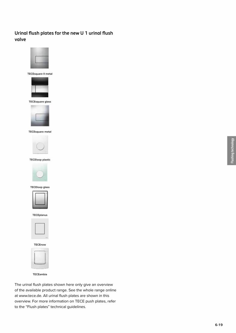
Urinal flush plates for the new U 1 urinal flush valve
TECEsquare II metal
TECEsquare glass
TECEsquare metal
TECEloop plastic
TECEloop glass
TECEplanus
TECEnow
TECEambia
The urinal flush plates shown here only give an overview of the available product range. See the whole range online at www.tece.de. All urinal flush plates are shown in this overview. For more information on TECE push plates, refer to the “Flush plates” technical guidelines.
Flus
hing
tech
nolo
gy
6-20
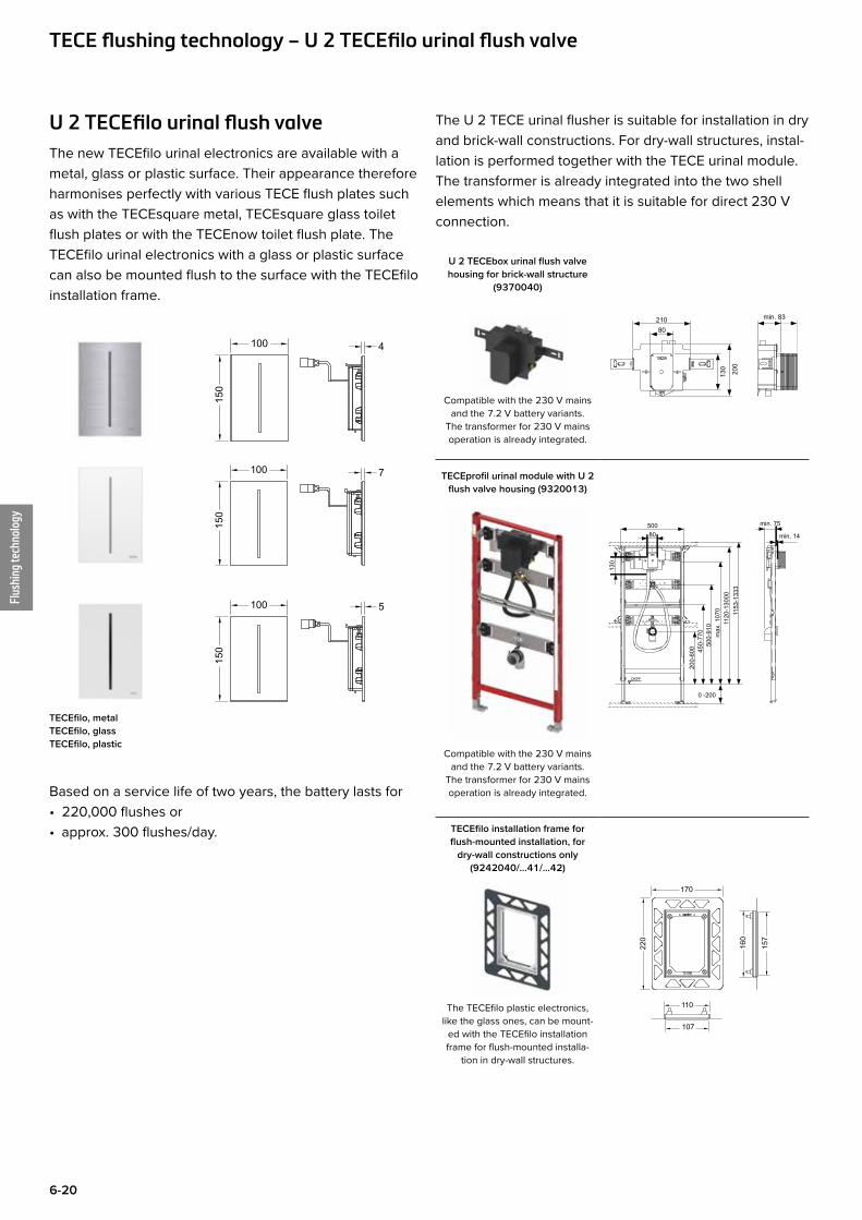
U 2 TECEfilo urinal flush valveThe new TECEfilo urinal electronics are available with a metal, glass or plastic surface. Their appearance therefore harmonises perfectly with various TECE flush plates such as with the TECEsquare metal, TECEsquare glass toilet flush plates or with the TECEnow toilet flush plate. The TECEfilo urinal electronics with a glass or plastic surface can also be mounted flush to the surface with the TECEfilo installation frame.
4100
150
100
150
7
5100
150
TECEfilo, metal TECEfilo, glass TECEfilo, plastic
Based on a service life of two years, the battery lasts for• 220,000 flushes or• approx. 300 flushes/day.
The U 2 TECE urinal flusher is suitable for installation in dry and brick-wall constructions. For dry-wall structures, instal-lation is performed together with the TECE urinal module. The transformer is already integrated into the two shell elements which means that it is suitable for direct 230 V connection.
U 2 TECEbox urinal flush valve housing for brick-wall structure
(9370040)
Compatible with the 230 V mains
and the 7.2 V battery variants. The transformer for 230 V mains operation is already integrated.
21080
200
130
min. 83
TECEprofil urinal module with U 2 flush valve housing (9320013)
Compatible with the 230 V mains and the 7.2 V battery variants.
The transformer for 230 V mains operation is already integrated.
min. 75
0 -200
500
1120
-130
00m
ax. 1
070
500-
910
450-
770
200-
600
OKFF
min. 1480
130
1153
-133
3
TECEfilo installation frame for flush-mounted installation, for
dry-wall constructions only (9242040/...41/...42)
The TECEfilo plastic electronics, like the glass ones, can be mount-
ed with the TECEfilo installation frame for flush-mounted installa-
tion in dry-wall structures.
170
157
110
107
220
160
TECE flushing technology – U 2 TECEfilo urinal flush valve
Flus
hing
tech
nolo
gy
6-21
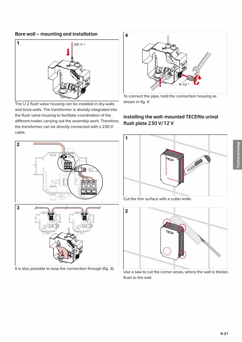
Bare wall – mounting and installation
1 230 V ~
The U 2 flush valve housing can be installed in dry-walls and brick-walls. The transformer is already integrated into the flush valve housing to facilitate coordination of the different trades carrying out the assembly work. Therefore, the transformer can be directly connected with a 230 V cable.
2
3
It is also possible to loop the connection through (fig. 3).
4
R 1/2 "!To connect the pipe, hold the connection housing as shown in fig. 4.
Installing the wall-mounted TECEfilo urinal flush plate 230 V/12 V
1
Cut the thin surface with a cutter knife.
2
Use a saw to cut the corner areas, where the wall is thicker, flush to the wall.
Flus
hing
tech
nolo
gy
6-22
3
min. 20 s
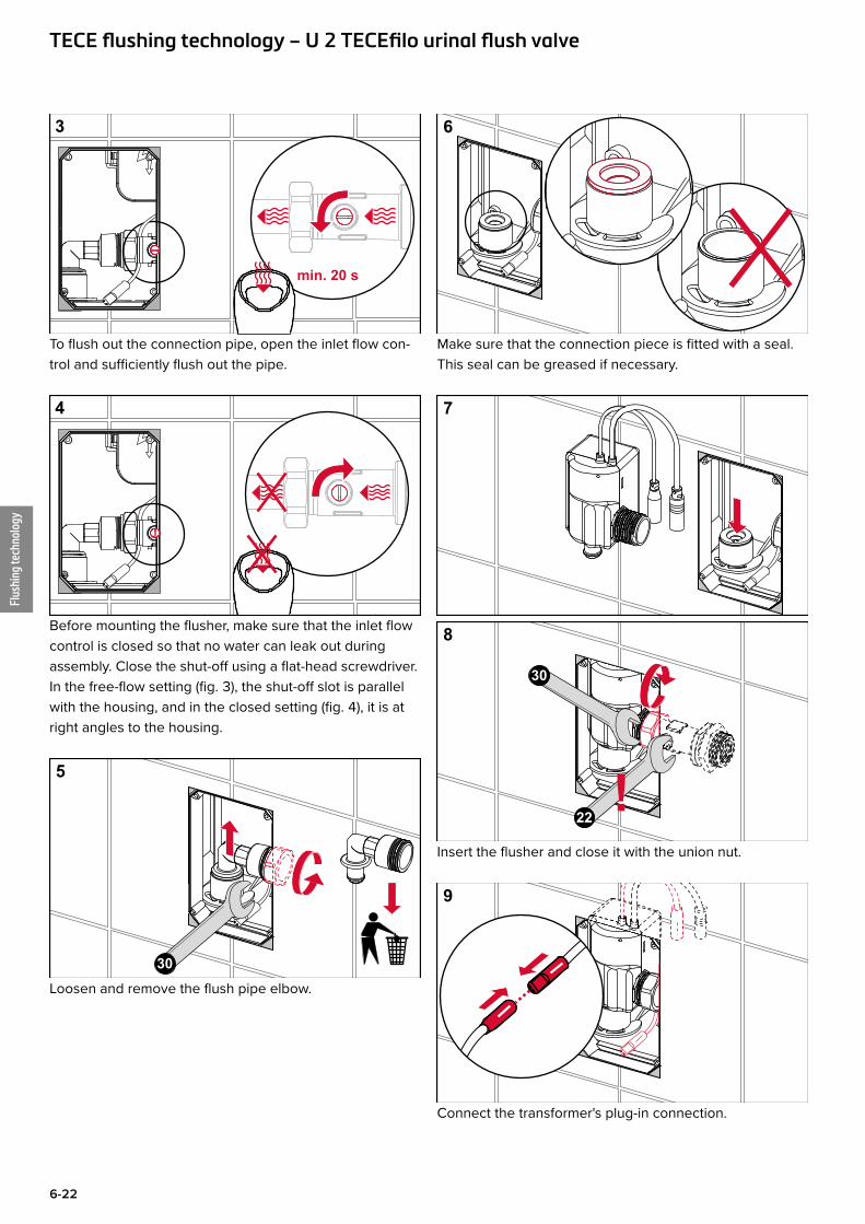
To flush out the connection pipe, open the inlet flow con-trol and sufficiently flush out the pipe.
4
Before mounting the flusher, make sure that the inlet flow control is closed so that no water can leak out during assembly. Close the shut-off using a flat-head screwdriver. In the free-flow setting (fig. 3), the shut-off slot is parallel with the housing, and in the closed setting (fig. 4), it is at right angles to the housing.
5
30Loosen and remove the flush pipe elbow.
6
Make sure that the connection piece is fitted with a seal. This seal can be greased if necessary.
7
8
30
!22
Insert the flusher and close it with the union nut.
9
Connect the transformer's plug-in connection.
TECE flushing technology – U 2 TECEfilo urinal flush valve
Flus
hing
tech
nolo
gy
6-23
10
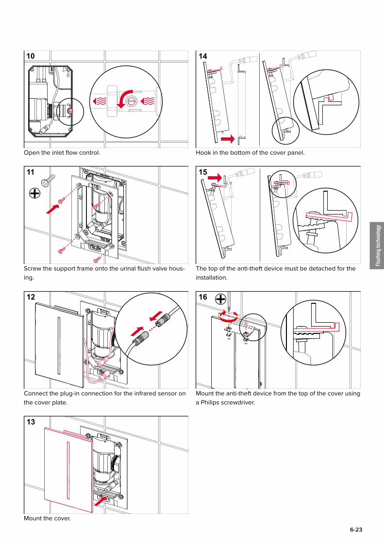
Open the inlet flow control.
11
Screw the support frame onto the urinal flush valve hous-ing.
12
Connect the plug-in connection for the infrared sensor on the cover plate.
13
Mount the cover.
14
Hook in the bottom of the cover panel.
15
The top of the anti-theft device must be detached for the installation.
16
Mount the anti-theft device from the top of the cover using a Philips screwdriver.
Flus
hing
tech
nolo
gy
6-24
17
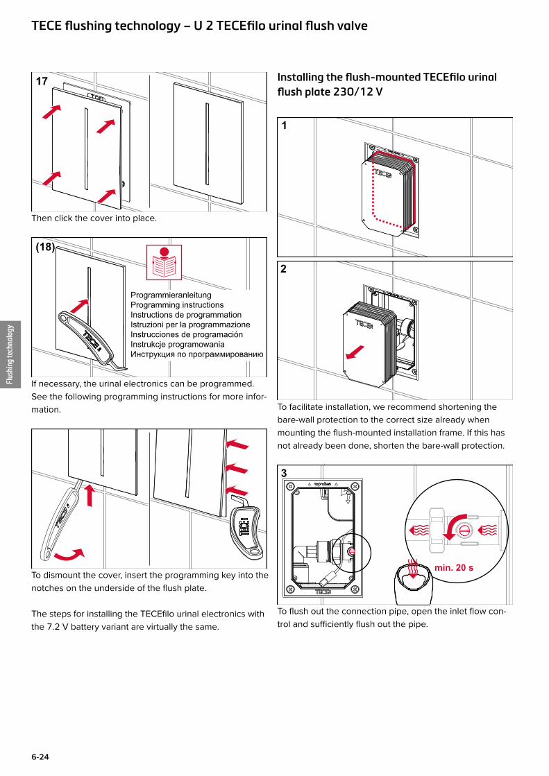
Then click the cover into place.
(18)
ProgrammieranleitungProgramming instructionsInstructions de programmationIstruzioni per la programmazioneInstrucciones de programaciónInstrukcje programowaniaИнструкция по программированию
If necessary, the urinal electronics can be programmed. See the following programming instructions for more infor-mation.
To dismount the cover, insert the programming key into the notches on the underside of the flush plate.
The steps for installing the TECEfilo urinal electronics with the 7.2 V battery variant are virtually the same.
Installing the flush-mounted TECEfilo urinal flush plate 230/12 V
1
2
To facilitate installation, we recommend shortening the bare-wall protection to the correct size already when mounting the flush-mounted installation frame. If this has not already been done, shorten the bare-wall protection.
min. 20 s
3
To flush out the connection pipe, open the inlet flow con-trol and sufficiently flush out the pipe.
TECE flushing technology – U 2 TECEfilo urinal flush valve
Flus
hing
tech
nolo
gy
6-25
4
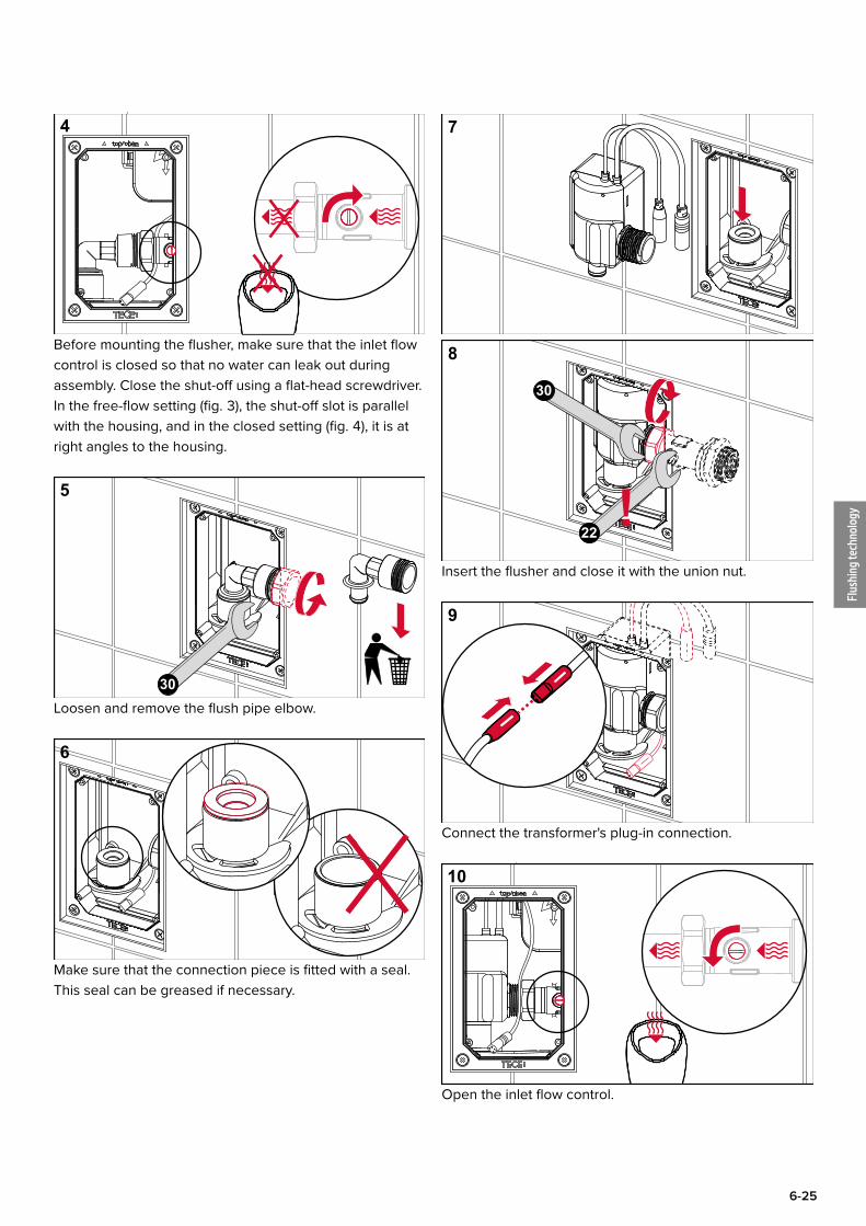
Before mounting the flusher, make sure that the inlet flow control is closed so that no water can leak out during assembly. Close the shut-off using a flat-head screwdriver. In the free-flow setting (fig. 3), the shut-off slot is parallel with the housing, and in the closed setting (fig. 4), it is at right angles to the housing.
5
30Loosen and remove the flush pipe elbow.
6
Make sure that the connection piece is fitted with a seal. This seal can be greased if necessary.
7
8
30
!22
Insert the flusher and close it with the union nut.
9
Connect the transformer's plug-in connection.
10
Open the inlet flow control.
Flus
hing
tech
nolo
gy
6-26
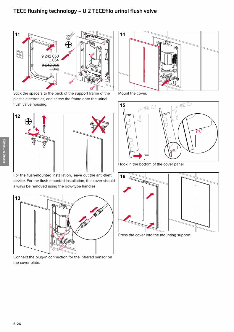
11
9 242 050...054
9 242 060...062
Stick the spacers to the back of the support frame of the plastic electronics, and screw the frame onto the urinal flush valve housing.
12
For the flush-mounted installation, leave out the anti-theft device. For the flush-mounted installation, the cover should always be removed using the bow-type handles.
13
Connect the plug-in connection for the infrared sensor on the cover plate.
14
Mount the cover.
15
Hook in the bottom of the cover panel.
16
Press the cover into the mounting support.
TECE flushing technology – U 2 TECEfilo urinal flush valve
Flus
hing
tech
nolo
gy
6-27
ProgrammieranleitungProgramming instructionsInstructions de programmationIstruzioni per la programmazioneInstrucciones de programaciónInstrukcje programowaniaИнструкция по программированию
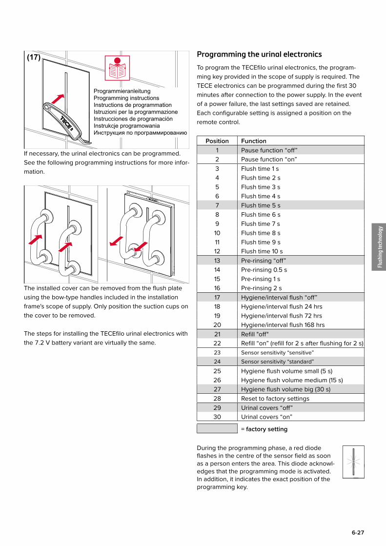
(17)
If necessary, the urinal electronics can be programmed. See the following programming instructions for more infor-mation.
The installed cover can be removed from the flush plate using the bow-type handles included in the installation frame's scope of supply. Only position the suction cups on the cover to be removed.
The steps for installing the TECEfilo urinal electronics with the 7.2 V battery variant are virtually the same.
Programming the urinal electronics
To program the TECEfilo urinal electronics, the program-ming key provided in the scope of supply is required. The TECE electronics can be programmed during the first 30 minutes after connection to the power supply. In the event of a power failure, the last settings saved are retained. Each configurable setting is assigned a position on the remote control.
Position Function1 Pause function “off”2 Pause function “on”3 Flush time 1 s4 Flush time 2 s5 Flush time 3 s6 Flush time 4 s7 Flush time 5 s8 Flush time 6 s9 Flush time 7 s10 Flush time 8 s11 Flush time 9 s12 Flush time 10 s13 Pre-rinsing “off”14 Pre-rinsing 0.5 s15 Pre-rinsing 1 s16 Pre-rinsing 2 s17 Hygiene/interval flush “off”18 Hygiene/interval flush 24 hrs19 Hygiene/interval flush 72 hrs20 Hygiene/interval flush 168 hrs21 Refill "off"22 Refill “on” (refill for 2 s after flushing for 2 s)23 Sensor sensitivity “sensitive”24 Sensor sensitivity “standard”25 Hygiene flush volume small (5 s)26 Hygiene flush volume medium (15 s)27 Hygiene flush volume big (30 s)28 Reset to factory settings29 Urinal covers “off”30 Urinal covers “on”
= factory setting
During the programming phase, a red diode flashes in the centre of the sensor field as soon as a person enters the area. This diode acknowl-edges that the programming mode is activated. In addition, it indicates the exact position of the programming key.
Flus
hing
tech
nolo
gy
6-28
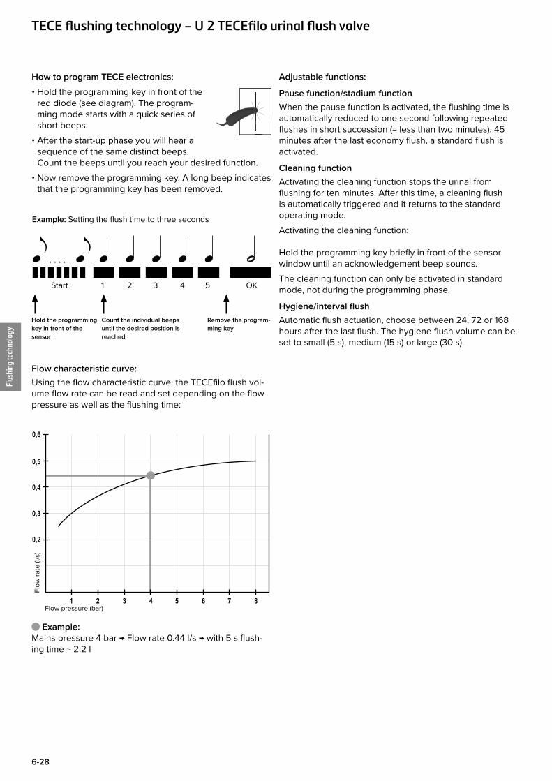
How to program TECE electronics: • Hold the programming key in front of the
red diode (see diagram). The program-ming mode starts with a quick series of short beeps.
• After the start-up phase you will hear a sequence of the same distinct beeps. Count the beeps until you reach your desired function.
• Now remove the programming key. A long beep indicates that the programming key has been removed.
Example: Setting the flush time to three seconds
. . . .
Hold the programming key in front of the sensor
Remove the program-ming key
Start 1 2 3 4 5 OK
Count the individual beeps until the desired position is reached
Flow characteristic curve:Using the flow characteristic curve, the TECEfilo flush vol-ume flow rate can be read and set depending on the flow pressure as well as the flushing time:
0,2
0,3
1 2 3 4 5 6 7 8
0,4
0,5
0,6
Flow pressure (bar)
Flow
rate
(l/s
)
Example:Mains pressure 4 bar → Flow rate 0.44 l/s → with 5 s flush-ing time ≈ 2.2 l
Adjustable functions:
Pause function/stadium functionWhen the pause function is activated, the flushing time is automatically reduced to one second following repeated flushes in short succession (= less than two minutes). 45 minutes after the last economy flush, a standard flush is activated.
Cleaning functionActivating the cleaning function stops the urinal from flushing for ten minutes. After this time, a cleaning flush is automatically triggered and it returns to the standard operating mode.Activating the cleaning function: Hold the programming key briefly in front of the sensor window until an acknowledgement beep sounds.The cleaning function can only be activated in standard mode, not during the programming phase.
Hygiene/interval flushAutomatic flush actuation, choose between 24, 72 or 168 hours after the last flush. The hygiene flush volume can be set to small (5 s), medium (15 s) or large (30 s).
TECE flushing technology – U 2 TECEfilo urinal flush valve
All data contained in the Technical Guidelines has been compiled with the utmost care. The correctness of the data presented cannot be guaranteed, however. TECE assumes no liability for damages resulting from the use of this information. Text and images are protected by copyright law.
© Copyright 2018, TECE GmbH, Hollefeldstraße 57, 48282 Emsdetten, Germany