Embed Size (px)
Citation preview

NASA Tec hnica I Paper 2276
. March 1984
.
NASA
Analysis of Rectangular Microstrip Antennas
NASA
2276 ' TP
I c.1
M. C. Bailey and M. D. Deshpande
LOAN COPY: RETURN TO AFWL TECHNICAL LIuRARY KIRTLAND AI%, N.M. 87117
https://ntrs.nasa.gov/search.jsp?R=19840012667 2018-06-22T20:00:43+00:00Z

TECH LIBRARY KAFB, NM
NASA Tech n ica I Paper 2276
1984
NASA National Aeronautics and Space Administration
Scientific and Technical Information Branch
I llllll Ill11 11111 Ill1 %I llll Ill11 1111 1111 0068170
Analysis of Rectangular Microstrip Antennas
M. C. Bailey Langley Research Center Hampton, Virginia
M. D. Deshpande The George Wash in@ o n University
Joint Institute f o r Advancement of Flight Sciences Langley Research Center Hampton, Virginia

INTRODUCTION
Because of many unique and a t t r a c t i v e p r o p e r t i e s (e.g., l i g h t weight, l o w cost , and c o m p a t i b i l i t y w i t h i n t e g r a t e d c i r c u i t s ) , microstrip antennas are f i n d i n g many a p p l i c a t i o n s . As a r e s u l t , i n recent yea r s a number of t h e o r e t i c a l and exper imenta l methods t o determine t h e i r e lec t romagnet ic p r o p e r t i e s have been proposed (ref. 1 ) . By t r e a t i n g t h e r e c t a n g u l a r antenna as t w o para l le l s lo t s in te rconnec ted by a l o w - impedance t ransmiss ion l i n e , it i s possible t o o b t a i n some u s e f u l p r e d i c t i o n s of t h e r a d i a t i v e p r o p e r t i e s (refs. 2 and 3 ) . However, t h i s simple model i s n o t adequate f o r p r e d i c t i n g t h e v a r i a t i o n of impedance wi th f eed loca t ion . Furthermore, t h e t r ansmiss ion - l ine model cannot be app l i ed t o microstrip p a t c h antennas o t h e r t han r ec t angu la r . To ana lyze a w i d e r v a r i e t y of microstrip pa tch shapes, a c a v i t y model h a s been proposed (ref. 4 ) . Although t h e c a v i t y model p r e d i c t s q u i t e a c c u r a t e l y t h e r a d i a t i o n p a t t e r n , it r e q u i r e s a semiempir ical c o r r e c t i o n f o r t h e resonant frequency i n o r d e r t o match t h e c a l c u l a t e d r e s u l t s wi th t h e exper imenta l da t a . This d i s c r e p - ancy may be due t o t h e f r i n g i n g f i e l d a t t h e edges of t h e pa tch n o t being incorpo- r a t e d i n t h e formula t ion and t h e d i e l e c t r i c s u b s t r a t e wi th f i n i t e t h i ckness be ing r ep laced by a homogeneous medium of equ iva len t d i e l e c t r i c cons tan t . There is , the re - f o r e , a need f o r more r igo rous a n a l y s i s techniques f o r m i c r o s t r i p antennas.
The r ec t angu la r and c i r c u l a r m i c r o s t r i p antennas have been analyzed by modeling t h e pa t ch as a g r i d o f w i r e s and s o l v i n g t h e r e s u l t i n g s t r u c t u r e numerical ly ( r e f . 5). Although t h e method appears t o be more a c c u r a t e and genera l , it r e q u i r e s a l o t of computer t i m e and s to rage . Furthermore, t o opt imize t h e computation, i t i s e s s e n t i a l t o know a p r i o r i t h e d i r e c t i o n of c u r r e n t f low on t h e patch.
Using t h e r e a c t i o n i n t e g r a l equa t ion i n conjunct ion wi th t h e method of moments, Newman e t a l . ( r e f . 6) propose a method which seems t o be q u i t e accu ra t e f o r p r e d i c t - i n g pa tch c u r r e n t , impedance, and r e sonan t frequency. However, Newman's method r e q u i r e s an unusual ly precise computation of t h e elements i n t h e impedance ma t r ix whi le s t i l l modeling t h e d i e l ec t r i c s u b s t r a t e as a n e q u i v a l e n t s emi - in f in i t e homoge- neous medium.
There have been o t h e r a t t empt s a t ana lyz ing m i c r o s t r i p antennas as open m i c r o - s t r i p c a v i t y r e s o n a t o r s f o r r e c t a n g u l a r and c i r c u l a r pa tches ( r e f s . 7 and 8). How- eve r , t h e s e formula t ions do n o t i nc lude t h e pa t ch e x c i t a t i o n i n t h e a n a l y t i c a l model- i ng , and t h e techniques cannot be extended t o microstrip a r r a y s .
The purpose of t h e p r e s e n t work is t o re formula te t h e problem t o overcome t h e d i f f i c u l t i e s encountered i n prev ious methods and t o e s t a b l i s h a foundat ion f o r ana- l y z i n g a v a r i e t y of e lec t romagnet ic problems related t o p r i n t e d - c i r c u i t antennas. The problem i s ana lyzed by f i r s t d e r i v i n g a dyadic Green's func t ion which s a t i s f i e s t h e boundary cond i t ions f o r a u n i t c u r r e n t l o c a t e d i n t h e p lane of t h e m i c r o s t r i p pa tch . By weight ing t h e Green 's f u n c t i o n wi th t h e electric c u r r e n t d e n s i t y and i n t e - g r a t i n g over t h e pa t ch , t h e r a d i a t e d e lec t romagnet ic f i e l d i s c a l c u l a t e d a t any p o i n t i n s i d e t h e d i e l e c t r i c . Coupled e l e c t r i c - f i e l d i n t e g r a l equa t ions for t h e unknown p a t c h c u r r e n t d e n s i t y are obta ined by f o r c i n g t h e t o t a l t a n g e n t i a l electric f i e l d on t h e pa t ch t o zero. With the proper basis and t e s t i n g f u n c t i o n s f o r t h e unknown cu r - r e n t d i s t r i b u t i o n , t h e i n t e g r a l equa t ions are reduced t o a mat r ix equat ion which may be so lved f o r the patch c u r r e n t . The c u r r e n t d i s t r i b u t i o n on the patch is then used t o determine t h e properties of t h e microstrip antennas.

Some f e a t u r e s of t h e p r e s e n t method are as follows: ( 1 ) it c o r r e c t l y accounts f o r t h e f i n i t e t h i ckness of t h e d i e l e c t r i c substrate and t h e e f f e c t of s u r f a c e waves; ( 2 ) it does n o t r e q u i r e high p r e c i s i o n i n t h e numerical computation of t h e ma t r ix elements; ( 3 ) it al lows improved convergence of t h e s o l u t i o n through proper cho ice o f t h e b a s i s and t e s t i n g func t ions ; ( 4 ) it can be extended t o m i c r o s t r i p pa t ches of any shape, provided one selects t h e proper b a s i s func t ions ; and (5) it i s s u i t a b l e f o r more involved problems of coupled microstrip antennas.
SYMBOLS
- A magnetic vec to r p o t e n t i a l
d d i e l e c t r i c s u b s t r a t e t h i c k n e s s
- E e l e c t r i c - f i e l d vec to r
amplitude of plane wave
x component of electric f i e l d due t o t h e i n c i d e n t plane wave (eq. ( 1 6 ) )
y component of t h e e lec t r ic f i e l d due t o t h e i n c i d e n t plane wave
EO
E;
E i Y
E8(9,4) 8 component of E
E ( e , @ ) 4 component of E
-
- 4
dyadic Green's f u n c t i o n
bidimensional Four i e r t ransform of G
magnetic-field vec to r
magnetic f i e l d due t o t h e i n c i d e n t plane wave
u n i t dyadic impulse c u r r e n t
s u r f a c e e l e c t r i c c u r r e n t d e n s i t y vec to r
- -
J-1 -
bidimensional Four i e r t ransform of J
x component o f 5 y component of j
complex c o e f f i c i e n t f o r x - d i r e c t e d c u r r e n t
complex c o e f f i c i e n t f o r y-directed c u r r e n t
wave propagat ion c o n s t a n t i n d i e l e c t r i c r eg ion
wave propagation c o n s t a n t i n f r e e space
-

Four i e r t r ans fo rm v a r i a b l e wi th respect t o x
Four i e r t r ans fo rm variable with r e s p e c t t o y
complex wave propagat ion c o n s t a n t i n z d i r e c t i o n
kX
kY
kZ
M + 1 number o f y -d i r ec t ed strips (see f i g . 2 )
m, n m,n subdomain of f i e l d
N + 1 number of x -d i r ec t ed strips (see f i g . 2 )
P19 p,q subdomain of source
r , 0 , @ coord ina te s of p o i n t i n s p h e r i c a l coord ina te system
E-plane dimension of t h e r e c t a n g u l a r p a t c h wX
(Wx/h&)o r e sonan t width of p a t c h
W H-plane dimension of t h e r e c t a n g u l a r p a t c h
r e c t a n g u l a r Ca r t e s i an coord ina te s of f i e l d p o i n t
Y
x,y, z
x ' ,y' , z ' r e c t a n g u l a r C a r t e s i a n coord ina te s of sou rce p o i n t
& A I L
X , Y , Z u n i t v e c t o r s a long x-, y-, and z-axis , r e s p e c t i v e l y
self-impedance of x-directed pa tch c u r r e n t (eq. ( 5 2 ) ) zxx
Pq Zmn mutual impedance between x -d i r ec t ed c u r r e n t s on m,n and p,q subdomains
(eq. (37)) xx
w Zmn mutual impedance between x- and y-directed c u r r e n t s on m,n and p , q
X y subdomains (eq. (38) 1
w
YX subdomains (eq. (39) Zmn mutual impedance between y- and x -d i r ec t ed c u r r e n t s on m,n and p,q
w - - Zmn mutual impedance between y - d i r e c t e d c u r r e n t s on m,n and p,q subdomains
YY (eq. (40) 1
r wave r e f l e c t i o n c o e f f i c i e n t
Ax = Wx/M + 1
= W / N + l Y AY
A(WX/h&) bandwidth for v o l t a g e standing-wave r a t io (VSWR) less than 3
3

1 ~ ( x - x ' ) d e l t a func t ion , 2 7 ~ 1:- e x p [ j ( x - x l ) w l dw
E r e l a t i v e p e r m i t t i v i t y of d i e l e c t r i c s u b s t r a t e r
wavelength i n d i e l e c t r i c substrate
pe rmeab i l i t y of d i e l e c t r i c substrate
AE
P E
w angular frequency , rad/s ec
S u p e r s c r i p t s :
I d i e l e c t r i c r e g i on
I1 f r e e space r eg ion
1/11 e i t h e r r eg ion I o r I1
THEORY
Genera 1
The geometry of t h e m i c r o s t r i p antenna i s shown i n f i g u r e 1. It c o n s i s t s of a t h i n conducting p l a t e , o r pa t ch , i n t h e form of a r e c t a n g l e , a square, a c i rc le , o r o t h e r geometric shapes embedded i n a d i e l e c t r i c s u b s t r a t e , with one s u r f a c e being grounded by a p e r f e c t l y conducting plane. Usually t h e m i c r o s t r i p antenna i s e x c i t e d e i t h e r by a m i c r o s t r i p t r ansmiss ion l i n e connected to one edge of t h e pa t ch o r by a c o a x i a l probe with t h e c e n t e r conductor extending through t h e ground plane and con- nec ted t o t h e patch. However, i n o r d e r t o determine t h e r e sonan t frequency, t h e bandwidth, and t h e r a d i a t i o n p a t t e r n , i t can be assumed t h a t t h e pa t ch i s e x c i t e d by a p l ane wave p o l a r i z e d i n t h e x -d i r ec t ion and wi th normal inc idence on t h e pa t ch , as shown i n f i g u r e 1. This model g ives r e s u l t s which are v a l i d f o r t h e p r a c t i c a l micro- s t r i p antenna s o long as t h e e x c i t i n g mechanism does n o t apprec i ab ly a l te r t h e cur- r e n t d i s t r i b u t i o n of t h e patch. For t h e d i e l e c t r i c s u b s t r a t e with a th i ckness less t h a n O.lhE, which is t h e case f o r most of t h e p r a c t i c a l m i c r o s t r i p antennas, t h e dimensions of t h e e x c i t i n g mechanism are much less than 1.0h, and, t h e r e f o r e , t h e f e e d connection produces only a s m a l l p e r t u r b a t i o n i n t h e r a d i a t i o n c h a r a c t e r i s t i c s of t h e antenna.
The s u r f a c e c u r r e n t induced on t h e pa t ch c o n t r o l s t h e antenna p r o p e r t i e s such as r a d i a t i o n p a t t e r n , i n p u t impedance, r e sonan t frequency, and bandwidth of t h e micro- s t r i p antenna and, t h e r e f o r e , must be determined f i r s t . L e t ~ ( x ' , y ' , z ' ) be t h e unknown s u r f a c e e lectr ic c u r r e n t d e n s i t y p r e s e n t on t h e patch. For a very t h i n p a t c h i n t h e plane z = z ' , J has on ly x- and y - d i r e c t e d components. However, f o r t h e g e n e r a l case, it i s assumed t h a t 5 has a l l t h r e e components. The e l ec t romagne t i c f i e l d due t o 5 can be obtained from
-
c1
k"

where t h e assumed t i m e v a r i a t i o n e x p ( j w t ) has been suppressed. 'Ihe magnetic vec to r p o t e n t i a l must s a t i s f y t h e wave equat ion
i n t h e d i e l e c t r i c ( r eg ion I) and must s a t i s f y
2-11 2 ;I1 v A ( x , y , z ) + ko ( X ? Y , Z ) = 0
i n f r e e space ( r eg ion 11).
If cI/II ( x , y , z , x ' , y ' , z ' ) i s - t h e dyadic Green's f u n c t i o n f o r regions I or I1 f o r a u n i t impulse c u r r e n t source T ( X ~ , ~ * ~ Z ~ ) embedded i n t h e d i e l e c t r i c s u b s t r a t e , t h e n t h e s o l u t i o n s of equa t ions ( 3 ) and ( 4 ) can be w r i t t e n i n t h e form
With t h e dyadic Green's f u n c t i o n from t h e appendix s u b s t i t u t e d i n t o equat ion (5) and t h e o r d e r of i n t e g r a t i o n changed, t h e magnetic v e c t o r p o t e n t i a l due t o t h e pa t ch c u r r e n t j ( x l , y l ) can be ob ta ined i n t h e form
where
and t h e components of t h e dyadic ? are de f ined i n t h e appendix.
5

The s c a t t e r e d f i e l d due t o t h e pa t ch c u r r e n t can be ob ta ined from equa t ion ( 2 ) i n t h e fol lowing form:
+ Cyx(kxrkyrz) j y ( k x , k Y I ] e x p ( j k X x + j k Y Y ) dkx dk Y
Y (k ,k r z ) j ( k x r k y ) ] e x p ( j k x + j k y ) dkx dk + I;YY x Y Y X Y
(9)
where
UL 2 zx
CXX(kxrkyrz) = (k2 - k:)f:x + j k x - az
I af z x
(kx,k r Z ) = -k k f1 + j k k - w Y x y xx x Y az
af I
Y X X Y x Y YY x y az Z Y I; (k ,k , z ) = -k k f1 + j k k -
6
I

2 ""zy + j k - 2 1 6 (k , k , z ) = (k 2 - k ) f YY x Y Y YY Y aZ
(1 4)
The t o t a l t a n g e n t i a l e lectr ic f i e l d a t t h e p l ane z = z ' c o n s i s t s of t h e scat- t e r e d f i e l d due t o t h e p a t c h c u r r e n t and t h e f i e l d due t o t h e i n c i d e n t plane wave. The s c a t t e r e d f i e l d due t o t h e pa t ch c u r r e n t i s given by equa t ions (8) and (91, and t h e electric f i e l d a t t h e p a t c h l o c a t i o n z = z ' by u s i n g t h e l a w s of r e f l e c t i o n and r e f r a c t i o n t o produce t h e following:
with t h e pa t ch removed i s ob ta ined
2 j s i n ( k z ' 1 exp( jkod) Ei =
c o s ( k d ) + j s i n ( k d 1 X (1 5)
By s e t t i n g t h e t o t a l t a n g e n t i a l electric f i e l d over t h e pa t ch equa l t o zero, t h e fol lowing i n t e g r a l equa t ions are obtained:
J w I" I" [6 (k ,k , z ' ) j x ( k x I k y ) i
E = X (2a)2k2 -" -a xx x y
+ Cyx(kxIk , z ' ) j (kx.ky)] exp( jkxx + j k y ) dkx dk Y Y Y Y
(1 6)
(k , k , z ' ) j (kx.ky)] e x p ( j k x + j k y ) dk + cYY x Y Y X Y X Y
dk (1 7)
The i n t e g r a l equa t ions (1 6) and ( 1 7 ) can be used t o determine t h e pa t ch c u r r e n t f o r a m i c r o s t r i p p a t c h of any a r b i t r a r y shape. However, when one tries t o s o l v e equa t ions (16) and (17) by t h e method of moments, it is d i f f i c u l t t o a r r i v e a t a proper expansion f u n c t i o n f o r t h e c u r r e n t d i s t r i b u t i o n on t h e pa t ch u n l e s s t h e geom- e t r y of t h e pa t ch is a n o rde red shape such as a r e c t a n g l e , a circle, o r a square. It may be concluded t h a t t h e a p p l i c a t i o n of equa t ions (16) and (17) may be l i m i t e d by complexity of t h e p a t c h shape.
Rad ia t ion P a t t e r n
The p a t c h c u r r e n t ob ta ined a f t e r s o l v i n g equa t ions (1 6 ) and (1 7) can be used t o e v a l u a t e t h e r a d i a t i o n p a t t e r n . It is w e l l known t h a t t h e f a r f i e l d due t o a r a d i a t - i n g a p e r t u r e i s d i r e c t l y r e l a t e d t o t h e Fourier t r ans fo rm of t h e t a n g e n t i a l electric f i e l d ove r t h e a p e r t u r e ( r e f . 9) . B n c e , t h e r ad ia t i -on p a t t e r n due t o a m i c r o s t r i p p a t c h embedded i n a d i e l e c t r i c s u b s t r a t e with one s u r f a c e grounded can be ob ta ined from a knowledge of t h e F o u r i e r t ransform of t h e electric f i e l d ove r t h e i n t e r f a c e
7

between f r e e space and t h e d i e l e c t r i c region. p l ane of z = d can be ob ta ined from equa t ions (8 ) and ( 9 ) as
The transformed electric f i e l d i n t h e
where ex and e are t h e F o u r i e r transforms of Ex and E The f a r f i e l d i s t h e n given by ( r e f . 9 )
Y Y.
E~ = (e c o s + + e s i n 4 - ) 2 exp(- jkor 1 X Y
jko cos 0 - e s i n 4 cos 8 - exp(- jkor 1
E 4 = ( e Y X ) 27cr
With t h e fo l lowing coord ina te t r ans fo rma t ion
k = k c o s + s i n 8 X 0
k = k s i n + s i n 8 Y 0
t h e f a r - f i e l d r a d i a t i o n p a t t e r n s become
(20)
( 2 1 )
8
where t h e q u a n t i t i e s Cxx(O,$), C ( e , $ ) , C m ( O , $ ) , and C y y ( O , $ ) are eva lua ted a t z = d. Also, j x ( O , $ ) and j?e,$) are t h e F o u r i e r transforms of t h e pa t ch c u r r e n t w i t h k, and ky r e p l a c e 3 by equa t ions ( 2 2 ) .
After cons ide rab le mathematical manipulation, t h e r a d i a t i o n p a t t e r n s can be w r i t t e n i n t h e form
where
- s i n 2 0 cos(Dk - 5 ) + j cos 8 sin(Dk - Z;) TE
2 D ( e , $ ) = J E r - s i n 0 cos D + j cos e s i n D
TE k k
D ( e , $ ) = E cos e c o s T M r D~ + j - s i n L @ s i n D k
Dk = kod \ J E ~ - s i n 2 0
0
9
-.-.. .. .

Applicat ion t o Rectangular Patch
Consider a m i c r o s t r i p antenna i n t h e form of a r e c t a n g u l a r pa t ch wi th r e s p e c t i v e E- and H-plane dimensions of Wx and W , as shown i n f i g u r e 2. 'Ihe c u r r e n t distri- bu t ion on t h e p a t c h must be expanded i n xerms of e igen func t ions which s a t i s f y t h e p rope r edge behavior such t h a t t h e normal component of t h e p a t c h c u r r e n t d e n s i t y i s z e r o a t t h e edge and t h e paral le l component approaches i n f i n i t y a t t h e edge. classic e igen func t ion s o l u t i o n of a problem invo lv ing edges, t h e s e edge c o n d i t i o n s are e x p l i c i t l y used t o select t h e e igen func t ions . h e r e t o use t h e e x a c t e igenfunct ions. Instead, one may expand t h e pa t ch c u r r e n t d e n s i t y i n terms of t r i a n g u l a r , s i n u s o i d a l , o r f l a t p u l s e s t o approximate t h e c u r r e n t d i s t r i b u t i o n . Therefore, t h e r e c t a n g u l a r pa t ch is d iv ided i n t o r e c t a n g u l a r subdo- mains which a l l o w one t o expand the c u r r e n t i n terms of ove r l app ing t r i a n g u l a r p u l s e s i n t h e d i r e c t i o n of t h e c u r r e n t and i n terms of f l a t p u l s e s or thogonal t o t h e cur- r e n t . Hence,
I n t h e
However, i t may be unnecessary
M N+l
where
m=l n=l
M+l N
J Y ( x , y ) =c >: jmn Y Qm(x) P,(Y)
m=l n=l
= o
% ( Y ) = 1
= o
Ax = W (M + 1 ) d
Ay = W /(N + 1 ) Y
10

and jy and jmn are t h e unknown complex x- and y-directed c u r r e n t c o e f f i c i e n t s fo r t h e m,n sddomain .
With equa t ion (71, t h e F o u r i e r transforms of t h e p a t c h c u r r e n t from equa- t i o n s (27) are
M N+l
m = l n=l
M+l N
m=l n=l
where
x +Ax F (k ,k 1 = /’” Pm(x) % ( Y ) expC-j(kxx + k y ) 1 dx dy
x,mn x Y yn-Ay ,-Ax Y
s i n ( k Ay/2) s i n ( k Ax/2) = A x A y [ kY A Y / 2 ][ kx Ax/2 1’
x exp[-jk x - jkyyn + j k ( A Y / 2 ) ] Y x m
s i n ( k Ay/2) s i n ( k Ax/2)
= Ax [-- kY AY/2 ]’[ kx 2x/2 ]
(29)
11

S u b s t i t u t i n g equa t ions (28) i n t o equa t ions (16) and (17) r e s u l t s i n t h e fo l lowing i n t e g r a 1 equa t ions :
X Y 1 x F (kx,k 1 exp(jkxx + j k y ) dk dk yImn Y Y
I f t h e method of moments is used wi th t e s t i n g f u n c t i o n s i d e n t i c a l t o t h e expan- s i o n func t ions , equa t ions (31) and (32) can be reduced t o a l g e b r a i c equat ions. Mul- t i p l y i n g equa t ion (31) by P (XI Q (y) and i n t e g r a t i n g w i t h r e s p e c t t o x and y g i v e s P 9
Likewise, mu l t ip ly ing equa t ion (32) by P ( y ) Q ( X I and i n t e g r a t i n g g i v e s q P
M N+l pq M+l N w E
m=l n=l Yx m=l n=l Y ? W
12

where
By varying p = 1, 2, ..., M and q = 1, 2, ..., N + 1 i n equa t ion (33) and by varying p = 1, 2, ..., M + 1 and q = 1, 2, ..., N i n equa t ion (341, M(N + 1) + (M + 1)N equa t ions wi th M(N + 1 ) + (M + 1)N unknowns are obtained. Hence, equa t ions (33) and (34) can be w r i t t e n i n t h e fo l lowing ma t r ix form, where t h e dimensions of each submatr ix are g iven below t h e submatrix:
M(N+l) xM(N+l) I M(N+l) X (M+1 )N M(N+1 ) Xl I I
(M+1 )NxM( N+1) i (M+1 )Nx (M+1) N (M+1) NX 1 _I. L

With t h e v a r i a b l e s changed such t h a t k = k c o s a and k = kop s i n a, t h e gen- e r a l i z e d impedance elements i n equa t ion ( 4 1 ) are given by X 0 Y
2
b (a, p) $2 z = c xx - k @ Ax cos a
2 0
2 - 1 ) ~ cos a S ,CB)] 2 x [ ( E r - p2 cos a> E , ( @ > - j ( E r
X cos[kop(xm - x 1 cos a] cos[ko@(yn - y,) s i n a]@ dp da ( 4 2 ) P
- k p Ax cos a 2 0 - -
sin(+ kof3 Ay s i n a ) 1 - k p Ay s i n a 2 0 - -
c o s a] sinkop(Yyn - yq + k) s i n c j p dg da ( 4 3 )
2 ,.- ,n/2 p;(: ko$ by s i n a! b(a ,
Pm: z = c YY - k p Ay s i n a
p=O a=O 2 0
x s i n [ k p(x - x 1 c o s a] s in[kop(yn - y ) s i n a]@ dg da ( 4 5 ) o m P 9
where
1 4

s i n (koz I JEr-82) I I
41-82 sin[k (d - 2 ' + Jg82 cos[ko(d - zl ) E
(48) 0 X
j {> s i n ( k o d i ] g ) + 4- cos ( k o d i g )
L -
I (cr - $') sin(kozl{-)
J1-82 sin(... dg) + \I.rp cos (ked,/-) (49)
and t h e i n t e g r a t i o n ove r t h e kx,k -plane h a s been reduced t o a n i n t e g r a t i o n ove r one quadrant by u s i n g t h e even and odz p r o p e r t i e s of t h e in t eg rand .
The impedance elements are computed by u s i n g numerical i n t e g r a t i o n techniques and p r o p e r l y account ing f o r t h e c o n t r i b u t i o n of s u r f a c e wave poles . The unknown complex c u r r e n t c o e f f i c i e n t s jy and jp are t h e n determined from equa t ion (41) by u s i n g ma t r ix inve r s ion .
Patch Cur ren t D i s t r i b u t i o n
The pa tch c u r r e n t d i s t r i b u t i o n can be ob ta ined by s o l v i n g t h e ma t r ix equa- t i o n (41 ) . 'Ihe m a t r i x e lements are numerically computed by u s i n g t h e Gauss quadra tu re numerical i n t e g r a t i o n technique. For a c c u r a t e computation, t h e upper l i m i t on t h e $ i n t e g r a t i o n must be terminated a t a s u f f i c i e n t l y l a r g e value. It w a s found numerical ly t h a t any i n c r e a s e i n t h e upper l i m i t above 600 does n o t change t h e values of t h e matrix elements appreciably.
Without loss of g e n e r a l i t y , t h e lef t -hand s i d e of equa t ion (41) may be assumed The'refore, t h e numerical r e su l t s for p a t c h c u r r e n t d i s t r i b u t i o n given t o be un i ty .
i n t h i s r e p o r t are normalized t o t h e t o t a l i n c i d e n t electric f i e l d on t h e patch, t h a t is, E: given i n equa t ion (15 ) .
15

Although t h e problem of t h e r e c t a n g u l a r microstrip antenna i s formulated cor- r e c t l y i n t e r m s of coupled i n t e g r a l equa t ions , t h e approximation t o t h e p a t c h c u r r e n t d i s t r i b u t i o n i s in t roduced when one tr ies t o solve t h e i n t e g r a l equa t ions by t h e method of moments or by Ga le rk in ' s method. The numerical s o l u t i o n of equa t ion (41) i s expected t o converge when t h e number of subdomains approaches i n f i n i t y . In prac- t ice, however, because of computer s t o r a g e and t i m e l i m i t a t i o n s , it is d e s i r a b l e t o o b t a i n a n answer wi th as few subdomains as poss ib l e . It is, t h e r e f o r e , important t o know t h e proper number of subdomains t o obtain a c c u r a t e v a l u e s of the p a t c h c u r r e n t d i s t r i b u t i o n .
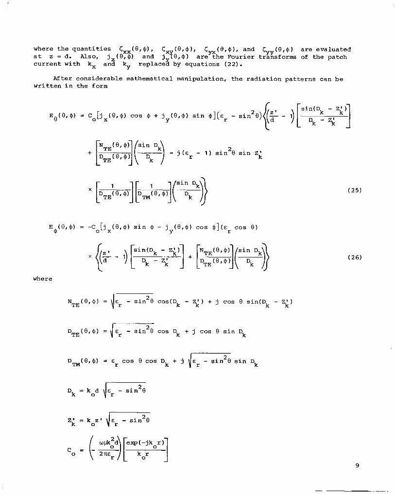
For a 1.0h square p a t c h (Wx = W ) i n f r e e space and i l l u m i n a t e d by a p l a n e E Y wave a t normal incidence, t h e p a t c h c u r r e n t converges t o t h e c o r r e c t va lue when
M > 7 and also N > 7 ( r e f . I O ) . The p r e s e n t problem becomes i d e n t i c a l t o t h e one i n r e f e r e n c e 10 when d = m and Er = 1. It is expected t h a t t h e p a t c h c u r r e n t ob ta ined a f t e r s o l v i n g equa t ion (41) f o r M > 7 and N > 7 w i l l o s c i l l a t e a b o u t t h e converged value of t h e p a t c h c u r r e n t i n r e f e r e n c e 10 as t h e s u b s t r a t e t h i c k n e s s d i s va r i ed . The p a t c h c u r r e n t a t t h e c e n t e r of t h e p a t c h ob ta ined a f t e r s o l v i n g equa- t i o n (41) f o r M = N = 7 i s p l o t t e d i n f i g u r e 3 as a f u n c t i o n of t h e s u b s t r a t e t h i c k n e s s f o r a d i e l e c t r i c c o n s t a n t of un i ty . As expected, both t h e real and imagi- nary par ts of t h e pa t ch c u r r e n t indeed o s c i l l a t e abou t t h e f r e e space value. For f u r t h e r c a l c u l a t i o n s , t h e number of subdomains i s s e l e c t e d such t h a t M = N = 11.
For f u r t h e r v e r i f i c a t i o n of t h e p r e s e n t method, it is important t o check t h e r e s u l t s ob ta ined wi th t h e p r e s e n t method with earlier known r e s u l t s . The t r a n s v e r s e - e l e c t r i c - s t r i p ( T E - s t r i p ) problem i s a l i m i t i n g case of t h e r e c t a n g u l a r pa t ch under t h e cond i t ion Wy + a. The pa tch c u r r e n t a t t h e c e n t e r , t h e r e f o r e , must asymptoti- c a l l y approach t h e TE-strip c u r r e n t ( r e f s . 11 and 1 2 ) as Wy approaches i n f i n i t y . Figure 4 shows t h e r e s u l t s are as expected.
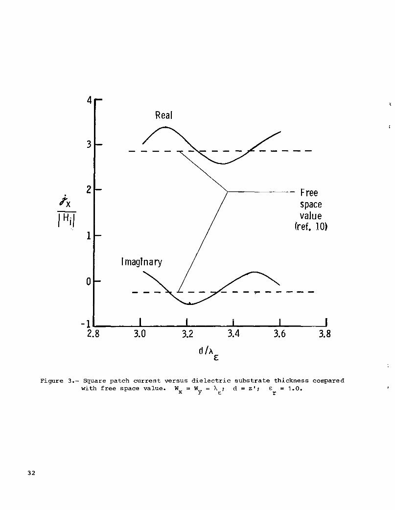
A f t e r checking t h e v a l i d i t y of t h e p r e s e n t formulat ion, equa t ion (41) is solved f o r a square patch. For x-polarized plane wave e x c i t a t i o n , t h e magnitude of t h e y-directed c u r r e n t i s very s m a l l compared with t h e magnitude of t h e x-directed c u r r e n t ( t y p i c a l l y 2 5 t o 30 dB less); t h e r e f o r e , Jy may be neglected. It i s advantageous t o s tudy t h e c u r r e n t d i s t r i b u t i o n on t h e patch, a l low one t o expres s t h e c u r r e n t i n t e r m s of more a p p r o p r i a t e b a s i s func t ions . Ihe c u r r e n t d i s t r i b u t i o n J x ( x , y ) , obtained a f t e r s o l v i n g equa t ion ( 4 1 ) , i s p l o t t e d i n f i g u r e 5 as a f u n c t i o n of x a t y = W /2 and as a f u n c t i o n of y a t x = W /2. I t i s clear from f i g u r e 5 t h a t c u r r e n t and i s uniform, excep t a t t h e edges, a long t h e d i r e c t i o n or thogonal t o t h e c u r r e n t ; t h e r e f o r e , it i s more a p p r o p r i a t e and advantageous t o expres s t h e pa t ch c u r r e n t d e n s i t y i n t h e fo l lowing form:
J,(x,y), which may
Y X Jx (x ,y ) i s almost s i n u s o i d a l i n t h e d i r e c t i o n of t h e
The assumption of uniform d i s t r i b u t i o n i n t h e y d i r e c t i o n g i v e s a va lue of jx s l i g h t l y h ighe r t han t h e t r u e value. of unknowns t o be eva lua ted is reduced from M ( N + 1) + ( M + 1)N t o 1. The ma t r ix equat ion (41) then reduces t o
With t h e above c u r r e n t d i s t r i b u t i o n , t h e number
$ = z j X xx x
16
(51 1

where
2 i i n ( 1 2 O Y k g W s i n a)]
I - k $W s i n a - 2 0 Y 1 2 2 - (k gWx cos a ) IT
0
and C, E , ( @ ) , and E , ( $ ) are g iven by equa t ions (461, (481, and ( 4 9 ) .
RESULTS
Patch Resonance
It i s in fo rma t ive t o p l o t t h e r ea l and imaginary parts of jx as a f u n c t i o n of t h e E-plane dimension, as shown i n f i g u r e 6. The p l o t h a s t h e c h a r a c t e r i s t i c r e so - n a n t behavior o€ a tuned c i r c u i t and can be used t o p r e d i c t t h e r e sonan t width (i.e., t h e r e sonan t f requency) of a r e c t a n g u l a r m i c r o s t r i p antenna. can be de f ined as t h e frequency a t which t h e imaginary par t of t h e above cr i ter ia , t h e r e sonan t frequency of a r e c t a n g u l a r p a t c h i s determined and p l o t t e d as a f u n c t i o n of t h e H-plane dimension i n f i g u r e 7 a long wi th a v a i l a b l e theo- re t ica l and experimental r e s u l t s from re fe rence 4. It should be noted t h a t t h e theo- re t ical p r e d i c t i o n of r e sonan t frequency u s i n g t h e c a v i t y model ( r e f . 4) r e q u i r e s a semiempirical c o r r e c t i o n . However, t h e p r e s e n t method of a n a l y s i s , without any co r - r e c t i o n , predicts t h e r e s o n a n t frequency w i t h i n t h e t o l e r a n c e l i m i t s of t h e d i e l e c - t r i c c o n s t a n t ( E = 2.62 f 0.02). r
The r e sonan t f requency J, i s zero. With
Resonant Width
With t h e r e sonan t c r i te r ia d e f i n e d i n t h e p rev ious s e c t i o n , t h e r e sonan t width of a r e c t a n g u l a r m i c r o s t r i p p a t c h i s computed as a f u n c t i o n of d i e l e c t r i c s u b s t r a t e t h i c k n e s s f o r t h e aspect r a t i o s s t a n t s & of 1.0, 2.5, 6.0, and y O . 0 . The va lues are p resen ted i n f i g u r e s 8 t o 11. d e s e c a l c u l a t i o n s show t h a t t h e r e sonan t width (normalized t o t h e dielectr ic wavelength) of a r e c t a n g u l a r m i c r o s t r i p p a t c h antenna g e n e r a l l y i n c r e a s e s wi th i n c r e a s e s i n t h e d i e l e c t r i c c o n s t a n t of t h e s u b s t r a t e and dec reases w i t h i n c r e a s e s i n t h e s u b s t r a t e t h i ckness .
W /Wx of 0.5, 1.0, and 1.5 and f o r d ie lectr ic con-
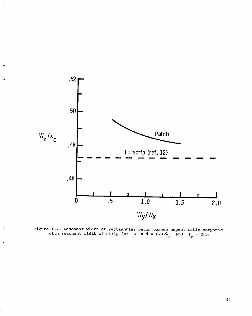
The re sonan t width of a r e c t a n g u l a r p a t c h is also p l o t t e d i n f i g u r e 12 as a f u n c t i o n of t h e aspect r a t io decrease i n t h e r e sonan t width of the patch. being l a r g e , t h e r e sonan t width of t h e r e c t a n g u l a r p a t c h w i l l approach a sympto t i ca l ly t h e r e sonan t width of t h e T E - s t r i p ( r e f . 12) .
Wy/Wx. An i n c r e a s e i n t h e aspect r a t i o causes a Under t h e l i m i t i n g case of Wy/W,
It is in fo rma t ive t o p l o t t h e r e s o n a n t width of t h e r e c t a n g u l a r p a t c h f o r a t h i c k d i e l e c t r i c s u b s t r a t e , as shown i n f i g u r e 13. These c a l c u l a t i o n s show t h e reso- n a n t width dec reases approximately l i n e a r l y with i n c r e a s e s i n s u b s t r a t e t h i c k n e s s
17
I I I 1111111.1.111 I 1111 _______-.......,.,.,, ,._..._...-_, ... .,.., ...,. ,.,_,,,.._.~~_~.,.,.,.l,,,.,,. ,.._I.__ ,,.,~,.,.,,,....,,,,,, 1111 I.,, 111 I

f o r d < 0.06hE. longer be used t o estimate t h e r e sonan t frequency of a m i c r o s t r i p antenna.
For d > 0.06AE, the curve i s n o longe r l i n e a r and s c a l i n g c a n no
I n some a p p l i c a t i o n s it is d e s i r a b l e t o cover t h e microstrip patch wi th a dielectric c o a t i n g t o protect t h e antenna from environmental cond i t ions . The reso- n a n t width of a r e c t a n g u l a r microstrip patch for v a r i o u s d i e l e c t r i c c o a t i n g t h i c k - nes ses is computed and i s p resen ted i n f i g u r e 14. These c a l c u l a t i o n s i n d i c a t e t h a t t h e r e sonan t width decreases with a n i n c r e a s e i n t h e t h i c k n e s s of t h e coa t ing .
Bandwidth
The bandwidth of microstrip antennas may be d e f i n e d as the band of f r e q u e n c i e s ove r which the i n p u t v o l t a g e standing-wave r a t io (VSWR) i n t h e f e e d l i n e i s less than a s p e c i f i e d va lue ( u s u a l l y 2 o r 3). Since the i n p u t impedance of a m i c r o s t r i p antenna i s p r o p o r t i o n a l t o the patch c u r r e n t , t h e i n p u t impedance v a r i a t i o n wi th frequency w i l l be t h e same as t h a t of the patch c u r r e n t . Hence, t h e i n p u t r e f l e c t i o n c o e f f i c i e n t v a r i a t i o n w i t h frequency can be c a l c u l a t e d from a knowledge of t h e pa t ch c u r r e n t dens i ty . Under t h e assumption of a u n i t v o l t a g e s o u r c e and a perfect imped- ance match a t resonance, the r e f l e c t i o n c o e f f i c i e n t r can be c a l c u l a t e d f r o m
1 - 1 'x ' x , r r = j , + j x , r
(53)
where j, i s the ampli tude of t h e pa t ch c u r r e n t d e n s i t y a t resonance. The magni- tude of the i n p u t r e f l e c t i o n c o e f f i c i e n t t h u s c a l c u l a t e d i s shown i n f i g u r e 15 as a f u n c t i o n of the pa tch s i z e f o r a squa re patch. For the i n p u t VSWR i n t h e f e e d l i n e t o be less than 3, the p e r c e n t bandwidth may be ob ta ined by
100 A(Wx/hE) Percent bandwidth =
(WX/AE lo (54)
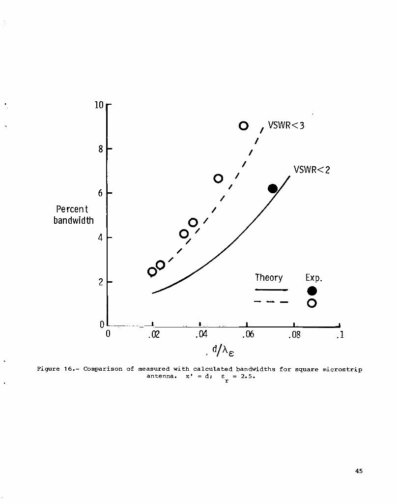
where A(Wx/hE) and ( W X / X E ) O are de f ined i n f i g u r e 15. The p e r c e n t bandwidth f o r a VSWR less than 2 can be determined i n a l i k e manner. The p e r c e n t bandwidth t h u s c a l c u l a t e d is compared wi th measured data i n f i g u r e 16 f o r probe-fed squa re patches. me appa ren t i n c r e a s e i n t h e measured p e r c e n t bandwidth may be due t o feed-connection i n s e r t i o n loss and copper loss i n t h e experimental models. me c a l c u l a t e d p e r c e n t bandwidths f o r r e c t a n g u l a r pa t ches are p resen ted i n f i g u r e s 17 t o 22 f o r aspect r a t i o s W y / w x of 0.5, 1.0, and 1.5 and dielectric c o n s t a n t s E of 1.0, 2.5, and 6.0. These c a l c u l a t i o n s show an i n c r e a s e i n bandwidth w i t h i n c r e a s e s i n d i e l e c t r i c s u b s t r a t e t h i ckness , which is c o n s i s t e n t w i t h p rev ious measured r e s u l t s ( r e f . 1 3 ) .
r
The p e r c e n t bandwidth of a square m i c r o s t r i p pa t ch wi th a t h i c k e r d i e l e c t r i c s u b s t r a t e is p resen ted i n f i g u r e 23. This c a l c u l a t i o n i n d i c a t e s t h a t a bandwidth up t o 20 p e r c e n t may be p o s s i b l e by c o n s t r u c t i n g t h e antenna on a t h i c k d i e l e c t r i c .
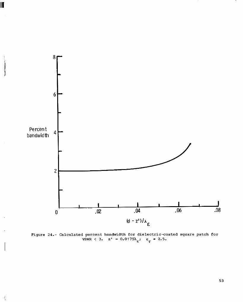
Figure 24 shows t h e e f f e c t of a d i e l e c t r i c c o a t i n g on t h e p e r c e n t bandwidth of a squa re patch. The c a l c u l a t i o n s shcw no appreciable change i n p e r c e n t bandwidth when
1 8

t h e cover t h i c k n e s s i s less t h a n 0.04hE. However, ( g r e a t e r t han 0.04h 1, t h e r e i s an i n c r e a s e i n t h e
&
Radiat ion P a t t e r n
With t h e x - d i r e c t e d c u r r e n t d i s t r i b u t i o n given
for t h i c k e r d i e l e c t r i c c o a t i n g s bandwidth of abou t 1 percent.
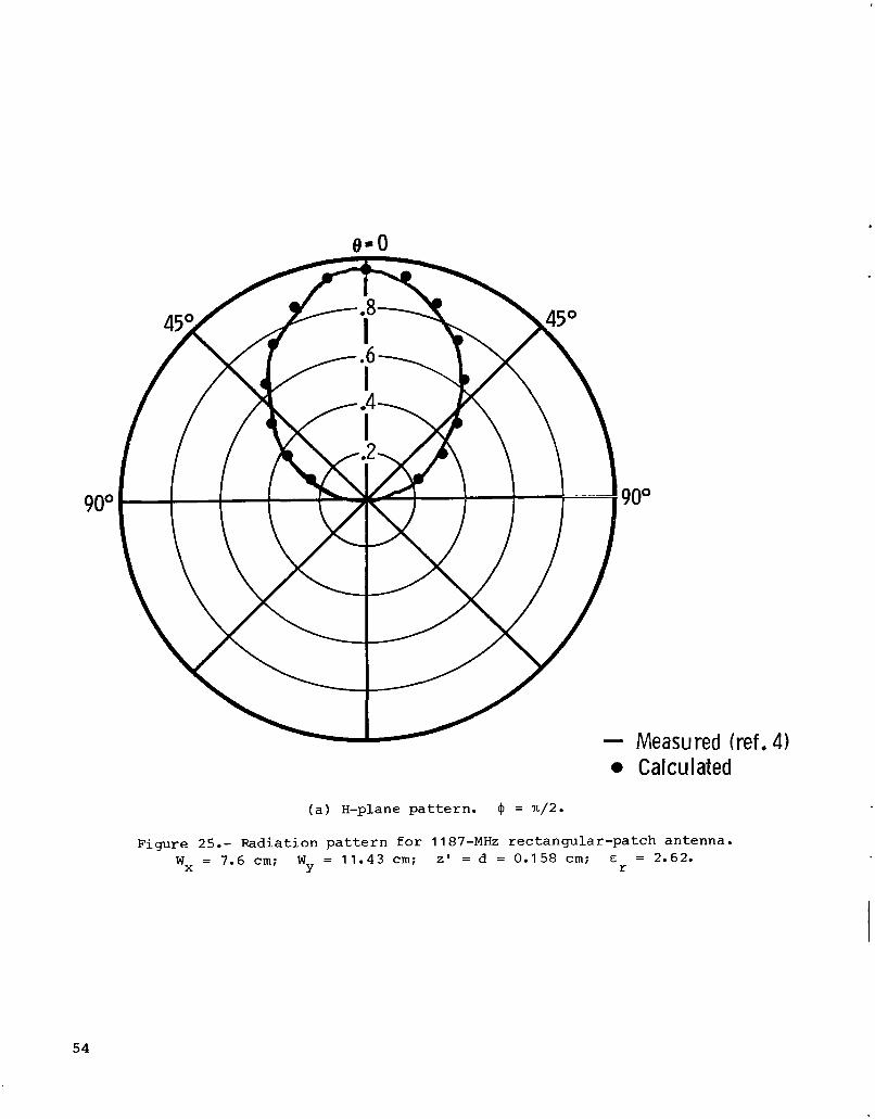
i n equa t ion (511, t h e r a d i a t i o n p a t t e r n s of a r e c t a n g u l a r m i c r o s t r i p antenna are computed from equa t ions (25) and (26). The r e s u l t s are p resen ted i n f i g u r e s 25 and 26 a l o n g with experimental d a t a ( r e f . 4) . There i s a close agreement between t h e c a l c u l a t e d and measured r a d i a t i o n patterns.
CONCLUSION
The dyadic Green's f u n c t i o n f o r a c u r r e n t sou rce l o c a t e d i n a d i e l e c t r i c w i t h one s u r f a c e grounded h a s been derived. Ihe dyadic Green's f u n c t i o n w a s used t o a r r i v e a t a set of coupled e l e c t r i c - f i e l d i n t e g r a l e q u a t i o n s f o r a m i c r o s t r i p p a t c h of a r b i t r a r y shape. As an example of t h e a p p l i c a b i l i t y t o microstrip antennas, t h e i n t e g r a l equa t ions w e r e so lved f o r a r e c t a n g u l a r p a t c h u s i n g Ga le rk in ' s method. It i s s h a m t h a t t h e p a t c h c u r r e n t can be used t o a c c u r a t e l y p r e d i c t t h e r e sonan t f r e - quency, t h e bandwidth, and t h e r a d i a t i o n p a t t e r n s of m i c r o s t r i p antennas. D a t a f o r a range of des ign parameters are p resen ted f o r t h e r e c t a n g u l a r microstrip antenna.
Langley Research Center Na t iona l Aeronautics and Space Adminis t ra t ion Hampton, VA 23665 January 25, 1984

APPENDIX
DERIVATION OF DYADIC GREEN'S FUNCTION
The expres s ion i n equa t ion ( 5 ) must s a t i s f y t h e w a v e equa t ions ( 3 ) and ( 4 ) ; t h e r e f ore,
(A1 1 2 =I V2~1(x,y,~Ix',y',~') + k G (X,~,Z,X',Y',Z') = -$ 6(x-x') 6(y-y') 6(z-z')
2=II 2 =I1 V G (x,y,z,x',y',z') + ko G (x,y,z,x',y',z') = 0 ( A 2 1
It i s clear from equa t ions ( A l ) and ( A 2 ) t h a t t h e Green's f u n c t i o n i s t h e e lectr ic v e c t o r p o t e n t i a l due t o a u n i t impulse c u r r e n t l o c a t e d a t t h e p o i n t (x',y',z').
It i s advantageous and less t e d i o u s t o o b t a i n t h e s o l u t i o n of equa t ions ( A l ) and ( A 2 ) i n t h e spectral domain. Therefore, t a k i n g t h e bidimensional Four i e r t ransform of both s i d e s of equa t ions ( A l ) and ( A 2 ) and u s i n g Sommerfeld's r a d i a t i o n c o n d i t i o n (ref. 1 4 ) y i e l d s
= -G 6 ( z - z ' ) exp[-j (k x' + k?' I ] X
2=II I1 2 =I1 a g (kx,k ,z,x',Y',z')
+ (k ) g (kX,ky,z,x',y',~') = 0 Y 2
aZ
where
k I = 1"fj ko "r
( A 3 1
( A 4 1
20
I

I
APPENDIX
kl' = Jk," - (k: + ky) 2
= -j {(kX 2 + ky 2 ) - ko 2
(kz > (k2 + k 2 ) ) X Y
(k: < (k2 + k 2 ) ) X Y
With a shortened n o t a t i o n g ='/I1, z1/''(k , k , z , x ' , Y ' , z ' ) may be expressed as X Y
where
-I/II - 1/11; + I/IIA 1/11; gX - gxx gyx y + gzx
;;/I1 = 1/11; + I/IIA 1/11; gxY gyy + gzy
-I/II = 1/11; + I/IIA 1/11; gZ g, gyz + gzz
=I/II The scalar components of g s a t i s f y t h e fo l lowing wave equat ions :
2 1
32 X
a gxx I 2 I 2 + (k gXx = -P h ( Z - 2 ' e-[-j (k x' + k ; ~ ' ) ]
+ (k I 2 ) gzz I = -p ~ ( z - z ' ) e=[-j (kxx' + k;J')]
az
(A7a 1
21

APPENDIX
Other components s a t i s f y t h e fo l lowing equa t ions f o r r eg ions I and 11:
n ..- I1 2 + (k 1 f I 1 = 0 a' f'- '-
aZ 2
where (excluding gxx, g1 , and g:, f o r reg ion I, and f I 1 denotes t h e r ight-hand scalar components oFyequations ( ~ 9 ) t o (AI 1 ) f o r r eg ion 11.
f1 denotes t h e r ight-hand scalar components of equa t ions (A9) t o (A1 1 ) I
!he s o l u t i o n of equa t ion ( A 1 2 ) has two p a r t s , complementary and p a r t i c u l a r . The complementary s o l u t i o n can be w r i t t e n i n t h e form
I I I = C+ exp(- jk z ) + Cix e x p ( j k z ) gxxc xx
where C:x and Cix a r e unknuwn cons tan ts . For t h e p a r t i c u l a r s o l u t i o n , t h e F o u r i e r t ransform of both s i d e s of equat ion ( A 1 2 1 i s taken wi th r e s p e c t t o z and y i e I d s
p exp[-j (kxx' + k y ' + kZz ' > ] I (kx,k , k Z , ~ ' , y ' , ~ ' ) = - . .
gxxp Y k2 - (k1)2 z
Taking t h e i n v e r s e t ransform wi th r e s p e c t t o z y i e l d s
I The in t eg rand i n equat ion (A191 h a s poles a t be eva lua ted through contour i n t e g r a t i o n i n t h e complex domain. Hence,
k, = kk ; t h e r e f o r e , equat ion (A191 can
22

APPENDIX
The complete s o l u t i o n of equa t ion (Al2) can be ob ta ined from equa t ions (Al7) and (A201 as
I + I I gXx = c xx exp( - jk z ) + C i x . e x p ( j k z )
Likewise, t h e s o l u t i o n s of equa t ions (Al3) , (Al4) , (Al5) , and (A161 are ob ta ined i n the fol lowing forms:
I + I I = C exp(- jk z ) + C- e x p ( j k z ) gYY YY YY
+ I I f1 = C exp(-jk z ) + C- e x p ( j k z )
+ I1 fl' = D exp(-jk z )
where C+ and C- are t h e c o e f f i c i e n t s of g1 exc lud in t h o s e given i n equa- t i o n s (A21 1 t o (A23), and D+ are t h e c o e f f i c i e n t s of g 91 .
The unknown c o e f f i c i e n t s * equa t ions (A21) t o (A251 are eva lua ted by app ly ing . 'Ihese boundary c o n d i t i o n s are ob ta ined by equat- -1jn1 t h e boundary c o n d i t i o n s on g i n g t o zero t h e t a n g e n t i a l electric f i e l d a t t h e p l ane c o n t i n u i t y of t a n g e n t i a l electric and magnetic f i e l d s a t t h e p l ane z = d. The
z = 0 and en fo rc ing t h e
23

APPENDIX
F o u r i e r transforms of t h e e l ec t romagne t i c f i e l d s i n r e g i o n s I and I1 may be ob ta ined through t h e fo l lowing r e l a t i o n s :
gI/II (kx,k , z , x ' , y ' , z ' = q g )( ;I/=) Y P (A261
where
S u b j e c t i n g t h e f i e l d ob ta ined from equa t ions ( A 2 6 ) and (A271 t o t h e boundary condi- t i o n s g ives , f o r z e r o t a n g e n t i a l e lectr ic f i e l d a t z = 0,
Con t inu i ty of t h e t a n g e n t i a l magnetic f i e l d a t z = d y i e l d s
2 4

APPENDIX
I I1 y =- as,,
a Z aZ
I I1 Z
I1 - I gzx - gzx
Continuity of the tangent ia l electric f i e l d a t z = d y i e l d s
I1 - I gxy - gxy
I1 g1 = gyx Yx
(A461
(A471
25

APPENDIX
I1 I I - l ) g W + k ( E - l )gyy = j
kX ( Y r
I1 I I
k ( E ~ - l ) g P + kX(Er - l )gxx = j Y
I1 I + kX(Er - l ) g = = j k Y ( E r - l ) g y z
I a Z
(A501
(A51 1
Sub jec t ing equa t ions ( A 2 1 ) t o (A25) t o t h e c o n d i t i o n s g iven b t o (A51) and s o l v i n g t h e se t of simultaneous equa t ions for C and C- r e s u l t s i n
equa t ions (A291 T
(A5 3) I = f I exp[-j(kxx' + k $ * ) ] gYY YY
I - I e-[-j (kxx' + k+f' I ] gzz - f zz
I g:x = f zx k x e=[-j (kxx' + k Y y ' ) ]
I = f I k exp[-j(kxx' + k $ ' ) ] gzY Z Y Y
where, f o r (z - 2') < 0,
I I k1 c o s ( k d ) + jk" s i n & d )
k o s (k'z 4 I I
I1 I I k E cos(k d ) + jk' s i n ( k d )
cos k l (d - 2') + jkI1cr s i n k (d - z ' ) - = - I
r f Z Z
26

APPENDIX
or, f o r ( z - z ' ) > 0,
I s i n k ( z - z ' )
k z
+ P k1 cos k l (d - z l ) + jk" s i n k l (d -
I I I k c o s ( k d ) + jk" s i n ( k d )
s i n k I ( Z - 2 ' )
f z z I =-w[ k z I ]
I s i n ( k z ) I k z
1 [cos ( k I z )j J I I1 I
r I I
kI1er cos (k d ) + j k l s i n ( k d )
- COS k (d - 2 ' ) + j k E s i n k (d - z ' )
k1
A l s o ,
p ( e I r = f = z y
- 1 ) s i n ( k I z ' ) cos (k I z ) (A61 1 I
I fZx
[k' cos (k I d ) + jk" ~ i n ( k ' d ) ] [ k ~ ~ e ~ cos(k I d ) + j k s i n ( k l d ) ]
=I I The o t h e r components of are zero. Likewise, t h e components of g are given by
I1 gxx 'I = f xx exp[-j(kxx' + k y ' ) ] exp[-jkI1(z - d ) ]
I1 gYY 'I = f YY e=[-j (kxxl + k g ' I ] exp[-jk"(z - d ) ]
I1 - I1 9,, - fzz exp[-j (kxx' + k?' I ] exp[ -jkI1 ( z - d ) ]
I1 gI1 = f k e=[ - j (k x' + k y ' ) ] exp[-jk''(z - a ) ] zx zx x X Y
I1 'I = f k exp[-j (kxx' + k y ' ) ] e=[-jk "(2 - d ) ]
gzY ZY Y Y
(A631
(A661
27
.... ,. .I .. 1.11 . I I I I ...--

APPENDIX
I1 fZz = -p(d - z ' )
where
I s i n k (d - z ' )
kl(d - 2')
I I I k cos k (d - z ' ) + jk1'Ez s i n k (d I1 I I [cos ( k Id )3
k &r cos (k d ) + jk' s i n ( k d )
=I I The o t h e r components of g are zero.
With t h e i n v e r s e F o u r i e r transform, t h e dyad ic Green's f u n c t i o n f o r r eg ions I and I1 i s ob ta ined from
28

REFERENCES
1. Carver, Kei th R.; and Mink, J a m e s W.: Microstrip Antenna 'Ilechnology. IEEE Trans. Antennas & Propag., vol. AP-29, no. 1, Jan. 1981, pp. 2-24.
2. Derneryd, Anders G. : Linea r ly Po la r i zed Microstrip Antennas. IEEE Trans. Antennas & Propag., vol. AP-24, no. 6, Nov. 1976, pp. 846-851.
3. Derneryd, Anders G.: A Theore t i ca l I n v e s t i g a t i o n of t h e Rectangular Microstrip Antenna Element. IEEE Trans. Antennas & Propag., vol. PIP-26, no. 4, Ju ly 1978, pp. 532-535.
4. Lo, Y. T.; Solomon, D.; and Richards, W. F.: Theory and Experiment on Microstrip Antennas. IEEE Trans. Antennas & Propag., vol. AP-27, no. 2, Mar. 1979, pp. 137-145.
5. A g r a w a l , Pradeep IC.; and Bai ley , M. C.: An Analys is Technique fo r Microstrip Antennas. IEEE Trans. Antennas & Propag., vol. AP-25, no. 6, Nov. 1977, pp. 756-759.
6. Newman, Edward H.; and Tulyathan, P rav i t : Analysis of Mic ros t r ip Antennas Using Moment Methods. IEEE Trans. Antennas & Propag., vol. AP-29, no. 1, Jan. 1981, pp. 47-53.
7. I t oh , Tatsuo; and Menzel, Wolfgang: A Full-Wave Analys is Method f o r open Micro- s t r i p s t r u c t u r e s . IEEE Trans. Antennas & Propag., vol. AP-29, no. 1 , Jan. 1981, pp. 63-68.
8. Araki, Kiyomichi; and I t o h , Tatsuo: I-hnkel Transform Domain Analysis of Open C i r c u l a r Microstrip Radia t ing S t ruc tu res . IEEE Trans. Antennas & Propag., vol. AP-29, no. 1, Jan. 1981, pp. 84-89.
9. Co l l in , Robert E.; and Zucker, Franc is J.: Antenna Theory. P a r t 1. McGraw-Hill Book Co., Inc. , c.1969.
10. Glisson, Al len Wilburn, Jr.: On t h e Development of Numerical Techniques for Trea t ing Arbi t rar i ly-Shaped Surfaces . Ph. D. D i s s . , Univ. of Mississippi, June 1978.
11. Bai ley, M. C.: Analysis of t h e P r o p e r t i e s of Microstrip Antennas Using S t r i p s Embedded i n a Grounded Dielectric Slab. 1979 I n t e r n a t i o n a l Symposium D i g e s t - Antennas and Propagat ion - Volume I, IEEE, 1979, pp. 370-373.
I
12. Bai ley, M. C.: A Bounds on t h e Resonant kequency of Rectangular Microstrip Antennas. NASA TM-81882, 1980. r
13. Bai ley , M. C.; C r o s w e l l , W i l l i a m F.; and Kirby, Richard C.: Antennas and Wave Propagation. E l e c t r o n i c s m g i n e e r s ' Handbook, Donald G. Fink and Donald Chr i s t i ansen , eds. , M c G r a w - H i l l , Inc., c. 1982, pp. 18-1 - 18-1 26.
14. Sommerfeld, Arnold: P a r t i a l D i f f e r e n t i a l Q u a t i o n s i n Physics. Academic Pres s , Inc., 1949.

Plane wave
f Region I1 (z I d)
Figure 1.- Geometry of m i c r o s t r i p antenna.
30

Ill1
Y
N
0
0
n
0
0
0
2
1
t A
Jx(X)
Figure 2.- Rectangular p a t c h wi th p u l s e subdomains and x -d i r ec t ed c u r r e n t d i s t r i bu t i on.
31
4
3
2
1
0
-1
Real
\ = Free
space va lue
kef. 10)
1 maginary / - - - I----
I 1 I 2.8 3.0 3.2 3.4 3.6 3.8
€ d /A
Figure 3.- Square pa t ch c u r r e n t versus d i e l e c t r i c s u b s t r a t e t h i ckness compared with free space value. Wx = W = Ac; d = 2 ' ; E = 1.0.
Y r 1
32

I
z
.8
.7
.6 JX
Ei -
.5 X
.4
.3 0 1 2 3 4
"y1% F i g u r e 4.- Comparison of rectangular patch current with TE-strip
W = 0.5h ; d = Z ' = 0.021 ; E = 2.5. X E E r
5
current.
33
I
4.0
3.0
2.0
Figure 5.- Patch c u r r e n t d i s t r i b u t i o n f o r a squa re patch. W = W = 0.4851 ; d = Z' = 0.02h ; E = 2.5. X Y E E r
-
- x = o
1 . o I -
34

3.2
2.4
1.6
.8
0
-. 8
-1.6
-2.4
I
. Imaginary. 1‘ /
-46 4 8 .50
0 0
0
.52
Figure 6.- Complex c u r r e n t c o e f f i c i e n t ve r sus dimension of square pa t ch . W = W ; d = Z ’ = 0.02h ; E = 2.5. X Y E r
35

1500
1490
Figure 7. - Resonant frequency of rectangular patch versus H-plane dimension. W = 5.95 cm; d = 2 ' = 0.159 c m ; E = 2.62 f 0.02 .
X r
-
I I I I 1 . 1 -I I I I I I I I I I
36

J
Figure 8.-
.50
.48
.46
.a
.42
.4c
Resonan
1 .o
\
\
I I I I 1 I 0 .M .04 .06
t width of r e c t a n g u l a r pa t ch ve r sus s u b s t r a t e t h i ckness z ' = d and E = 1.0.
r
f o r
37

w l h X &
.gure 9.-
.50
.4a
.46
.441,- ~. I I ~~~ ~~ I 0 .M .04 .06
d / A €
Resonant width of rectangular pa tch v e r s u s s u b s t r a t e t h i c k n e s s f o r z' = d and = 2.5.
38

X €
.46
.44
Figure 10.- Resonant width of rectangular patch versus substrate thickness for z' = d and er = 6.0.
- D
- I---!- ~- - ~ -1 I I
39

.46 0 .@ .04 .06
L
I I i I I I
Figure 1 1 .- Resonant width of r e c t a n g u l a r patch v e r s u s s u b s t r a t e t h i c k n e s s for z' = d and E~ = 10.0.
40
w l h X E
.52
I
.50 I
.
.48
F .46
1- .5 1 .o 1.5 2 .o 0
Figure 12.- Resonant width of r e c t a n g u l a r pa t ch ve r sus a s p e c t r a t i o compared with r e sonan t width of s t r i p f o r z' = d = 0.02h and E = 2.5.
E r
41

w l h X €
.6-
D
.5
.4 - L
.3 I P 1 I I I I I 0 .10 .15 20
d l h €
Figure 13.- Resonant width of square p a t c h for t h i c k s u b s t r a t e s . Z ' = d; E = 2.5.
r
'0
42

.50
.48
.46
.a
I
F i g u r e 14. - Resonant width of die lectr ic -coated square patch versus coating thickness . 2 ' = 0.0175h ; E = 2.5.
E r
43
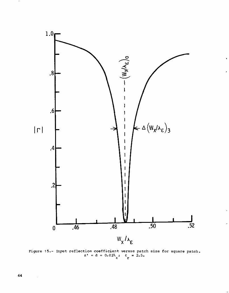
Figure 1 5 . - Input r e f l e c t i o n c o e f f i c i e n t versus patch s i z e f o r square patch. Z ' = d = 0.02h ; E = 2.5.
E r
44
Pe rcen t bandwidth
10
8
6
0 / V S W R < 3 /
/ / VSWR<2
Theory Exp.
4
2
0 0 .02 .04 .06 .08 .1
Figure 16.- Comparison of measured wi th c a l c u l a t e d bandwidths €or squa re microstrip antenna. z ' = d; E = 2.5.
r
45

c 0 .a? .04 .06
16
14
12
10
Percent bandwidth
6
4
2
d h,
Figure 17.- Calcu la ted p e r c e n t bandwidth f o r r e c t a n g u l a r pa t ch f o r E = 1.0. r VSWR < 3; Z ' = d.
46

.
10
8
6
Percent bandwidth
4
2
0
Figure 18.- Calculated percent bandwidth for rectangular patch for E = 2.5. VSWR < 3; Z ' = d. r
47

8
6
Percent bandwidth 4
2
I I I I I I 0 i o 02 04
El d / A
Figure 19.- Calcu la ted p e r c e n t bandwidth f o r r e c t a n g u l a r p a t c h f o r E = 6.0. r VSWR < 3; Z ' = d.
48
-. . ... -. .. .

10
8
6 Pe rcen t
bandwidth
J
4
2
0 .02 .06
Figure 20.- Calcu la ted p e r c e n t bandwidth f o r squa re pa t ch fo r VSWR < 3. Z' = d.
49

Percent bandwidth
6-
4 -
111
2 -
I
I --I 0 .@ .04 .06 0 .@ .04
I .06
Figure 21.- Ca lcu la t ed p e r c e n t bandwidth f o r r e c t a n g u l a r pa t ch f o r E = 6.0. r VSWR < 2; Z' = d.
50

Pe rcen t bandwidth
Figure 22.- Calcu la ted p e r c e n t bandwidth f o r squa re p a t c h for VSWR < 2. z' = d.
51

24
22
20
18
16
14
Percent 12 bandwidth
10
8
6
4
2
Figure 23.- C a l
I
- . cu l a t ed p e r c e n t bandwidth f o r square pa t ch wi th t h i c k d
s u b s t r a t e €o r VSWR < 3. z' = d; E = 2.5. r
i .e l e c t r i c
52
Pe rcen t bandwidth
Figure 24.- Ca lcu la t ed p e r c e n t bandwidth f o r dielectric-coated squa re patch f o r VSWR < 3. Z' = 0.0175hC; & = 2.5. r
53
90°
( a ) H-plane p a t t e r n . 0 = x/2.
90°
- Measured (ref. 4) 0 Calculated
Figure 25.- Radia t ion p a t t e r n fo r 1 1 87-MHz rec tangular -pa tch antenna. Wx = 7.6 c m ; Wy = 11.43 c m ; z ' = d = 0.158 c m ; E = 2.62. r
54

e = O
90°
(b) E-plane p a t t e r n . 4 = 0.
Figure 25.- Concluded.
- Measu red (ref. 4) Calculated
55

90'
'ref. 4
(a) H-plane p a t t e r n . 4 = 7C/2.
Figure 26.- Radiat ion p a t t e r n f o r 804-MHz rec tangular -pa tch antenna. W, = 11.43 c m ; Wy = 7.6 c m ; z ' = d = 0.158 c m ; E r = 2.62.
56

90°
e = o
90°
-Measured (ref. 4) Calculated
(b) E-plane p a t t e r n . I$ = 0.
Figure 26.- Concluded.
57

-. r 1. Report No.
NASA TP-2276 3. Recipient's Catalog No. 2. Government Accession No.
. ~. ~ . . -.
5. Report Date
6. Performing organization Code ~~ - .
March 1984
.. - _ 506-58-23-01
c - - . - . . . ..
8. Performing Organization Report No.
L- 1 5698 .... ~ _ _ _ _ .... .
10. Work Unit No.
- . -. . . - - _ _ 11. Contract or Grant No.
- - 13. Type of Report and Period Covered
Technical Paper
14. Sponsoring Agency Code
.- . _ _ ~ . - -
15. Supplementary Notes
M. C. Bailey: Langley Research Center, Hampton, Virginia . M. D. Deshpande: The George Washington Universi ty , J o i n t I n s t i t u t e f o r Advancement
of F l i g h t Sciences , Hamp ton , Virginia .
16. Abstract
The problem of m i c r o s t r i p antennas covered by a d i e l e c t r i c s u b s t r a t e i s formulated t e r m s of coupled i n t e g r o - d i f f e r e n t i a l equa t ions with t h e c u r r e n t d i s t r i b u t i o n on t h conduct ing p a t c h as an unknown q u a n t i t y . The Galerkin method i s used t o s o l v e f o r t h e unknown pa tch c u r r e n t . Using t h e p r e s e n t formulat ion, t h e r a d i a t i o n p a t t e r n , t l
17, Key Words (Suggested Antennas
by Author(s)) Bandwidth
Mic ros t r ip Electromagnetics Resonant frequency Rad ia t ion p a t t e r n s
Unc las s i f i ed - Unlimited
Subject Category 32 __ ~ - _ _
19. Security Classif. (of this report) 20. Security Classif. (of this page) 21. No. of Pages 22. Price
Unclas s i f i ed Unclassif ied 58 A0 4 - - -
For sale by the National Technical Information Service, Springfield, Virginia 22161 NASA-Langley , 1984
!

I
National Aeronautics and Space Ad m in ist rat ion
Washington, D.C. 20546 Official Business
Penalty for Private Use, $300
THIRD-CLASS BULK RATE (&-- Postage and Fees Paid National Aeronautics and Space Administration NASA451
USMAIL =I c
POSTMASTER: If Undeliverable (Section 158 Postal Manual) Do Not Return
I