Embed Size (px)
DESCRIPTION
Team Ninja. Introduction/Overview. Implementation of Subsystems MCU board Chassis/Motor/Motor Driver Sensor Parts List Schedule Division of Labor. MCU Board. MCU Board Block Diagram. MCU Pinout. MC68711K4 Microprocessor. Features 8-bit opcodes and data 16-bit addressing - PowerPoint PPT Presentation
Citation preview

Team NinjaTeam Ninja
Introduction/OverviewIntroduction/OverviewImplementation of Subsystems
– MCU board– Chassis/Motor/Motor Driver– Sensor
Parts ListScheduleDivision of Labor
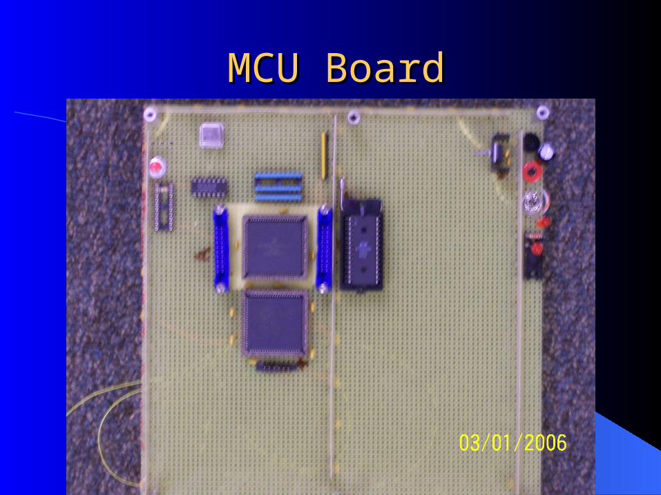
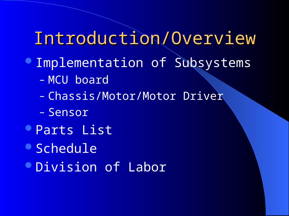
MCU BoardMCU Board
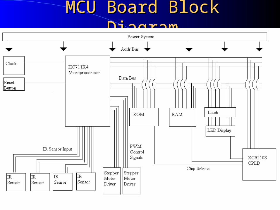
MCU Board Block MCU Board Block DiagramDiagram
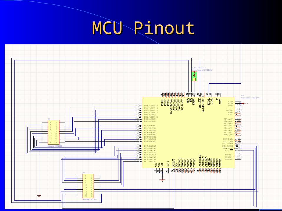
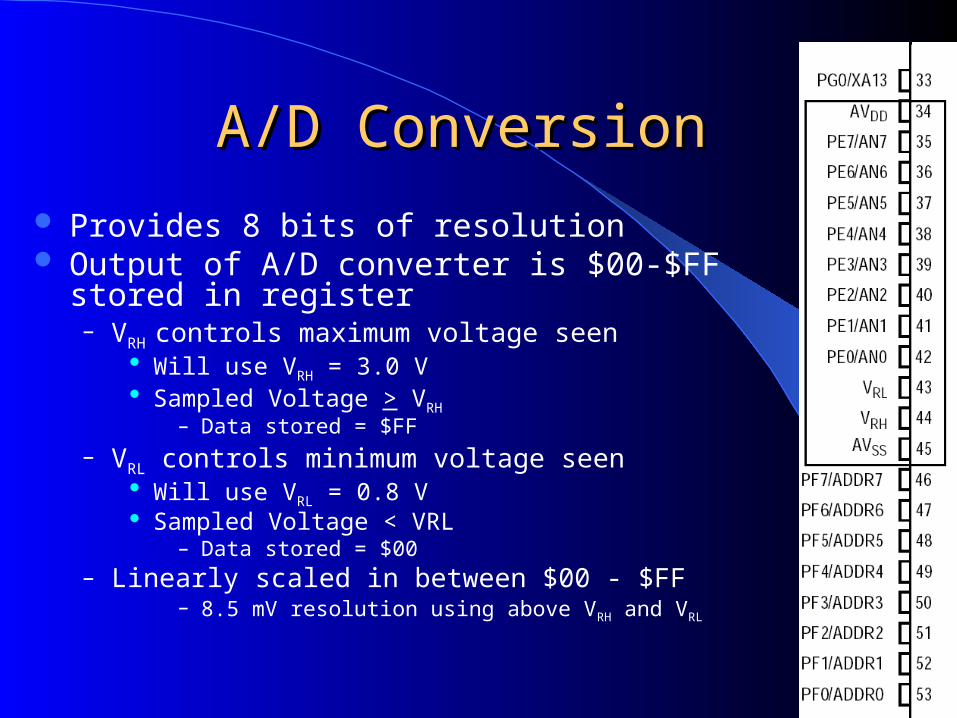
MCU PinoutMCU Pinout
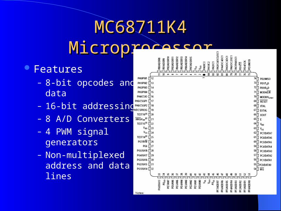
MC68711K4 MicroprocessorMC68711K4 Microprocessor
Features– 8-bit opcodes and data– 16-bit addressing– 8 A/D Converters– 4 PWM signal
generators– Non-multiplexed
address and data lines
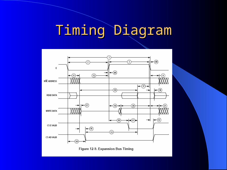
Timing DiagramTiming Diagram
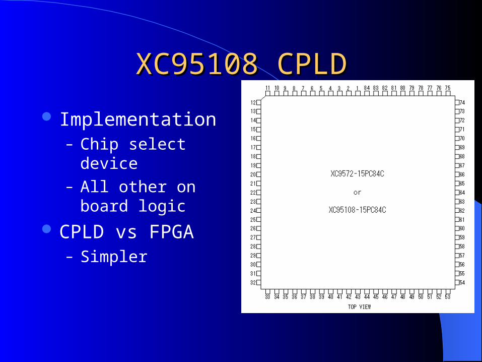
XC95108 CPLDXC95108 CPLD
Implementation– Chip select device– All other on board
logic CPLD vs FPGA
– Simpler
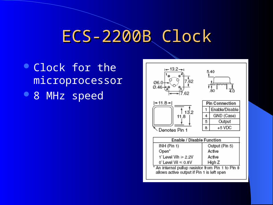
ECS-2200B ClockECS-2200B Clock
Clock for the microprocessor
8 MHz speed
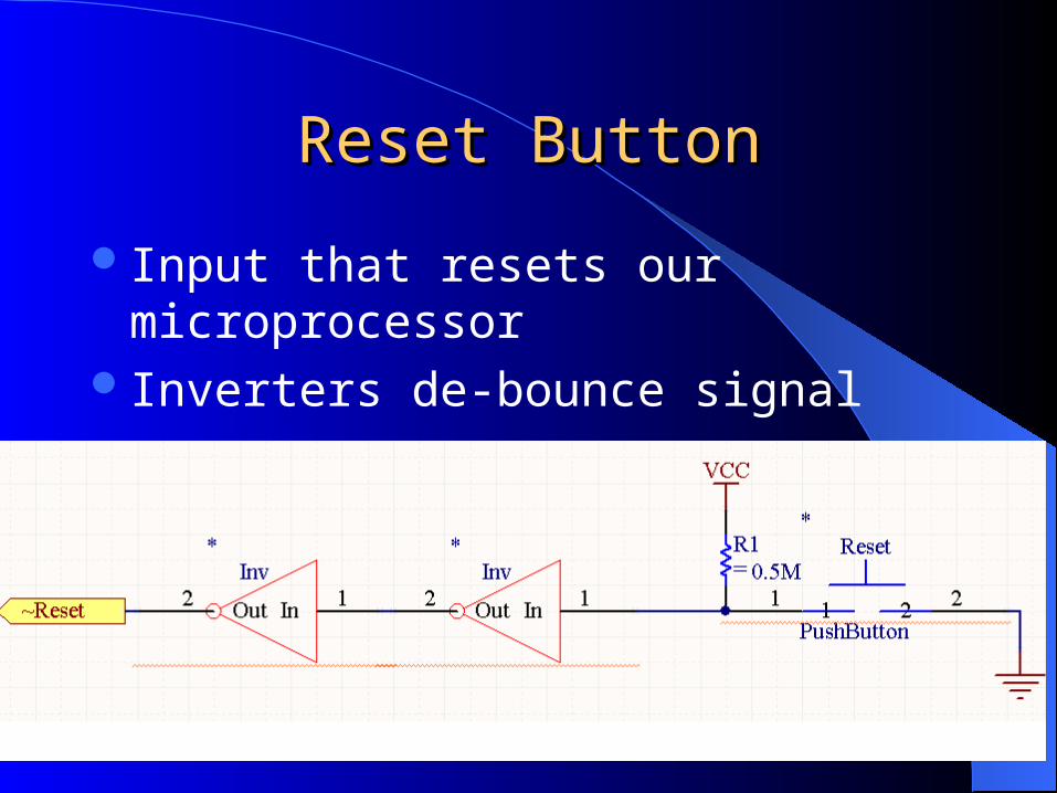
Reset ButtonReset Button
Input that resets our microprocessorInverters de-bounce signal
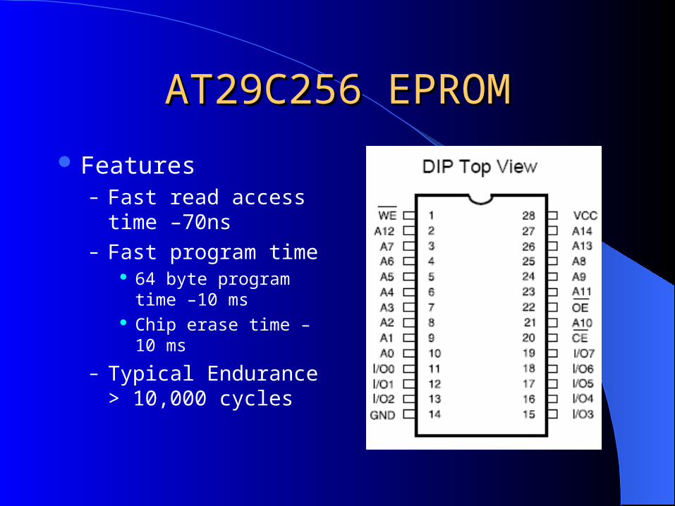
AT29C256 EPROMAT29C256 EPROM
Features– Fast read access
time –70ns– Fast program time
64 byte program time –10 ms
Chip erase time – 10 ms
– Typical Endurance > 10,000 cycles
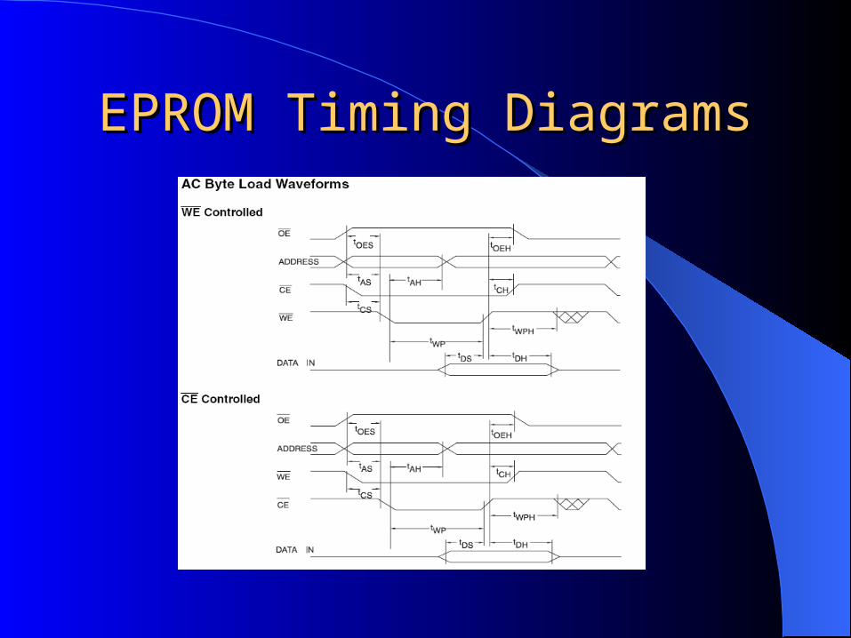
EPROM Timing DiagramsEPROM Timing Diagrams
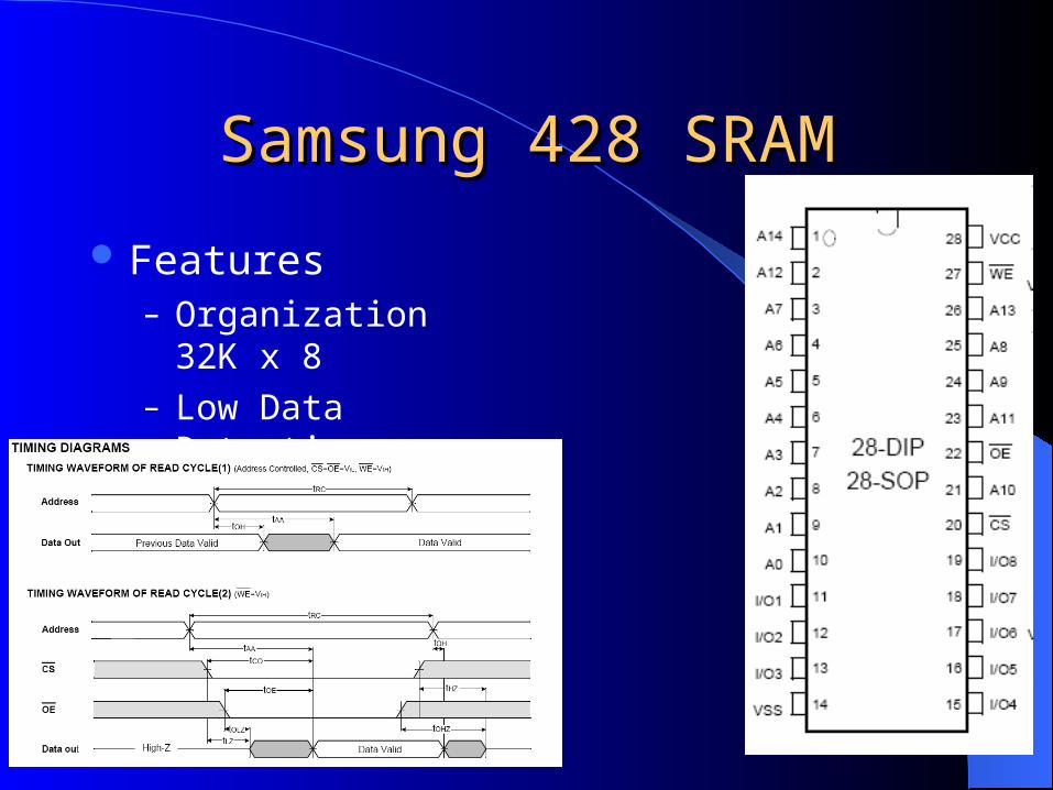
Samsung 428 SRAMSamsung 428 SRAM
Features– Organization 32K
x 8– Low Data
Retention Voltage
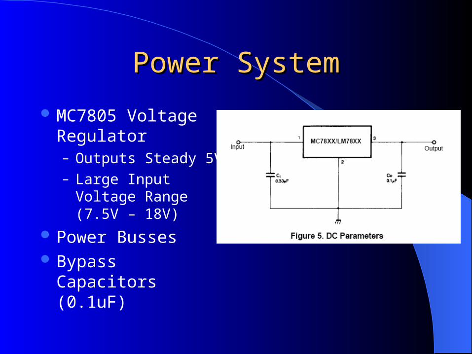
Power SystemPower System
MC7805 Voltage Regulator– Outputs Steady 5V– Large Input Voltage
Range (7.5V – 18V)
Power Busses Bypass Capacitors
(0.1uF)
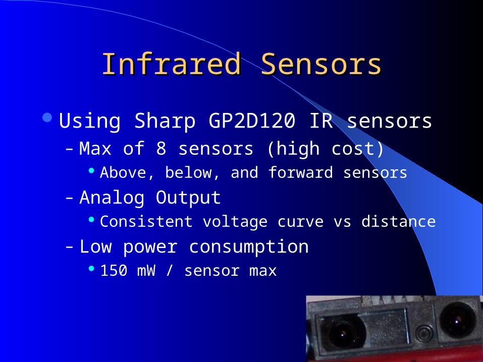
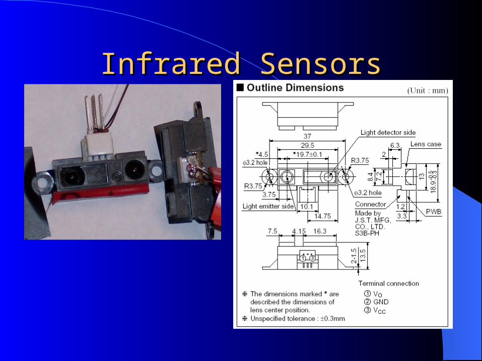
Infrared SensorsInfrared Sensors
Using Sharp GP2D120 IR sensors– Max of 8 sensors (high cost)
Above, below, and forward sensors
– Analog Output Consistent voltage curve vs distance
– Low power consumption 150 mW / sensor max
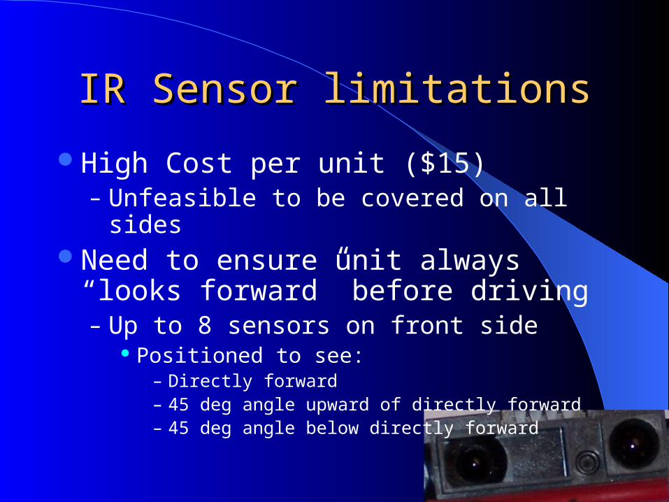
IR Sensor limitationsIR Sensor limitations
High Cost per unit ($15)– Unfeasible to be covered on all sides
Need to ensure unit always “looks forward” before driving– Up to 8 sensors on front side
Positioned to see:– Directly forward– 45 deg angle upward of directly forward– 45 deg angle below directly forward
Infrared SensorsInfrared Sensors
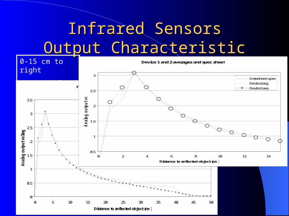
Infrared SensorsInfrared SensorsOutput CharacteristicOutput Characteristic
Device 1 and 2 averages and spec sheet
0
0.5
1
1.5
2
2.5
3
3.5
0 5 10 15 20 25 30 35 40 45 50
Distance to reflected object (cm)
Anal
og o
utp
ut vo
ltag
e (V
)
Datasheet spec
Device2avg
Device1avg
Device 1 and 2 averages and spec sheet
0.5
1
1.5
2
2.5
3
0 2 4 6 8 10 12 14
Distance to reflected object (cm)
Analo
g o
utp
ut voltage (V
)
Datasheet spec
Device2avg
Device1avg
0-15 cm to right
0-50cm below
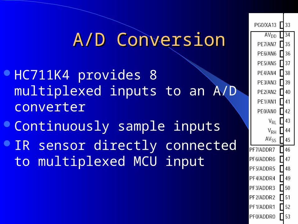
A/D ConversionA/D Conversion
HC711K4 provides 8 multiplexed inputs to an A/D converter
Continuously sample inputsIR sensor directly connected to multiplexed
MCU input
A/D Conversion A/D Conversion
Provides 8 bits of resolution Output of A/D converter is $00-$FF stored in register
– VRH controls maximum voltage seen Will use VRH = 3.0 V Sampled Voltage > VRH
– Data stored = $FF
– VRL controls minimum voltage seen Will use VRL = 0.8 V Sampled Voltage < VRL
– Data stored = $00– Linearly scaled in between $00 - $FF
– 8.5 mV resolution using above VRH and VRL
A/D ReconstructionA/D Reconstruction
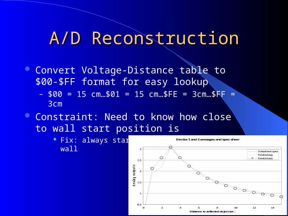
Convert Voltage-Distance table to $00-$FF format for easy lookup– $00 = 15 cm…$01 = 15 cm…$FE = 3cm…$FF = 3cm
Constraint: Need to know how close to wall start position is
Fix: always start more than 5cm away from wallDevice 1 and 2 averages and spec sheet
0.5
1
1.5
2
2.5
3
0 2 4 6 8 10 12 14
Distance to reflected object (cm)
Analo
g o
utp
ut voltage (V) Datasheet spec
Device2avg
Device1avg
A/D ReconstructionA/D Reconstruction7-Segment LED7-Segment LED
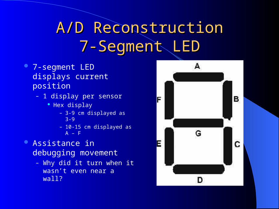
7-segment LED displays current position– 1 display per sensor
Hex display – 3-9 cm displayed as 3-9
– 10-15 cm displayed as A – F
Assistance in debugging movement– Why did it turn when it
wasn’t even near a wall?
A/D ReconstructionA/D Reconstruction7-Segment LED Implementation7-Segment LED Implementation
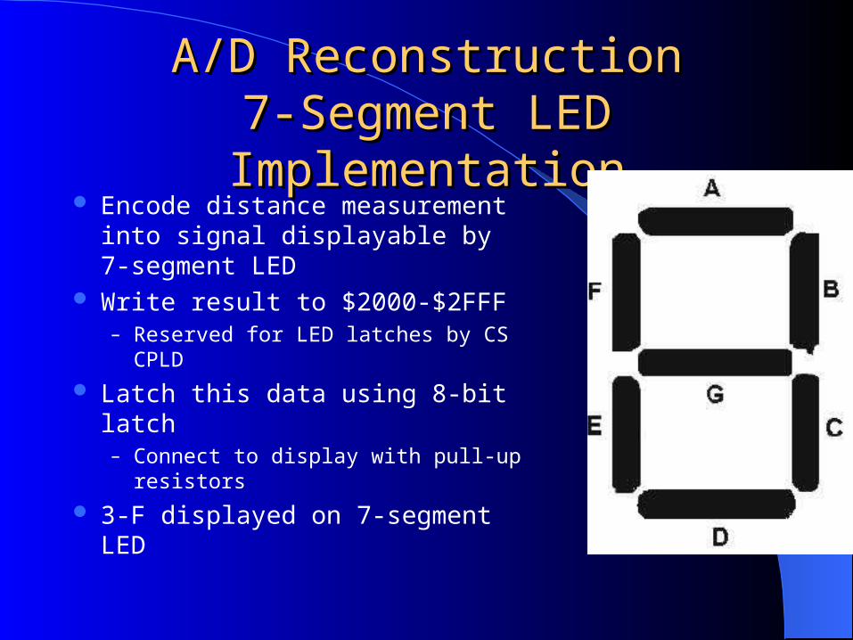
Encode distance measurement into signal displayable by 7-segment LED
Write result to $2000-$2FFF– Reserved for LED latches by CS CPLD
Latch this data using 8-bit latch– Connect to display with pull-up resistors
3-F displayed on 7-segment LED
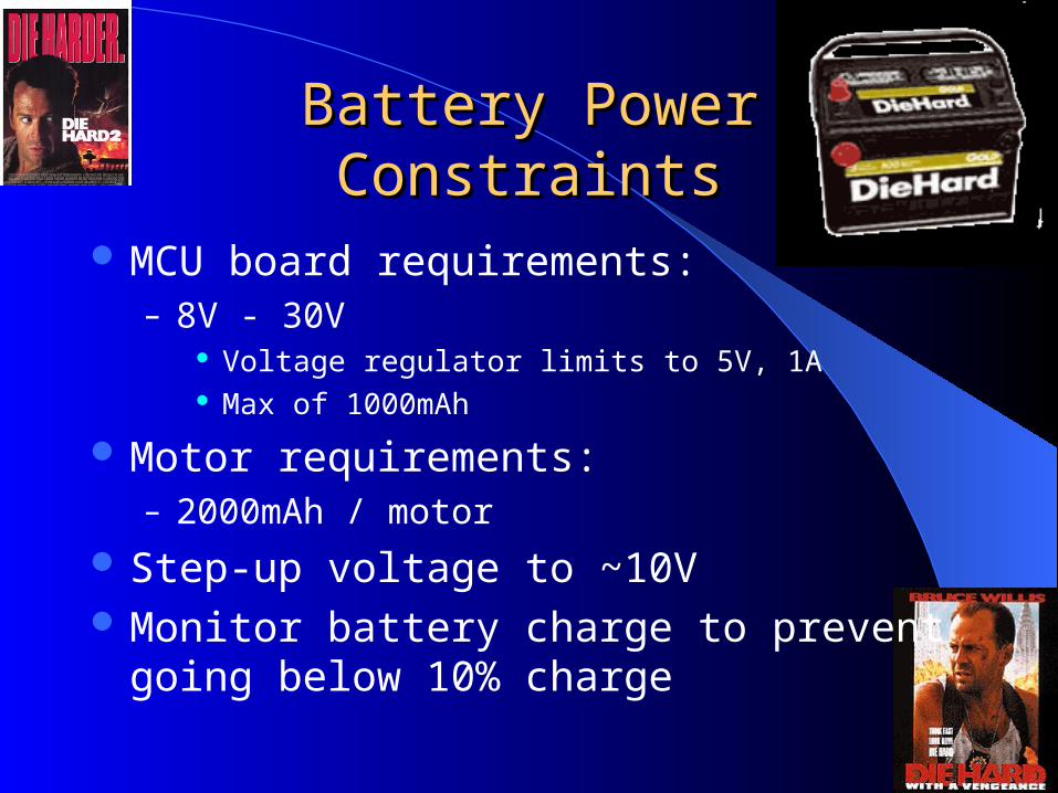
Battery PowerBattery PowerConstraintsConstraints
MCU board requirements:– 8V - 30V
Voltage regulator limits to 5V, 1A Max of 1000mAh
Motor requirements:– 2000mAh / motor
Step-up voltage to ~10V Monitor battery charge to prevent going below
10% charge
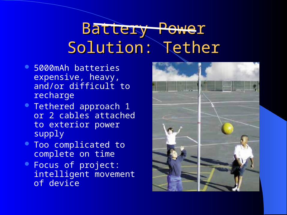
Battery PowerBattery PowerSolution: TetherSolution: Tether
5000mAh batteries expensive, heavy, and/or difficult to recharge
Tethered approach 1 or 2 cables attached to exterior power supply
Too complicated to complete on time
Focus of project: intelligent movement of device
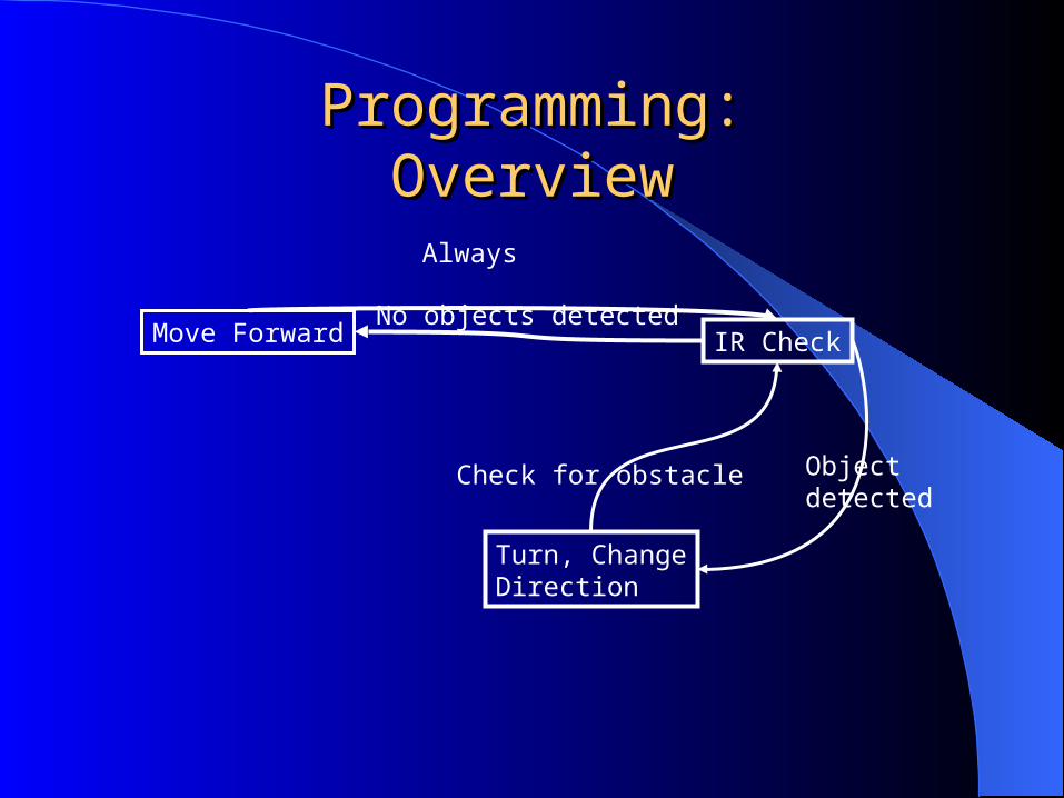
Programming:Programming:OverviewOverview
Move Forward IR Check
Turn, ChangeDirection
Always
No objects detected
Objectdetected
Check for obstacle
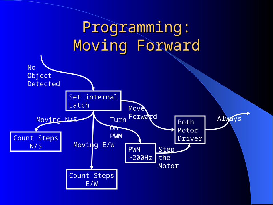
Programming:Programming:Moving ForwardMoving Forward
Set internalLatch
PWM~200Hz
BothMotorDriverCount Steps
N/S
Count StepsE/W
NoObjectDetected
MoveForwardMoving N/S
Moving E/W
TurnOnPWM
SteptheMotor
Always
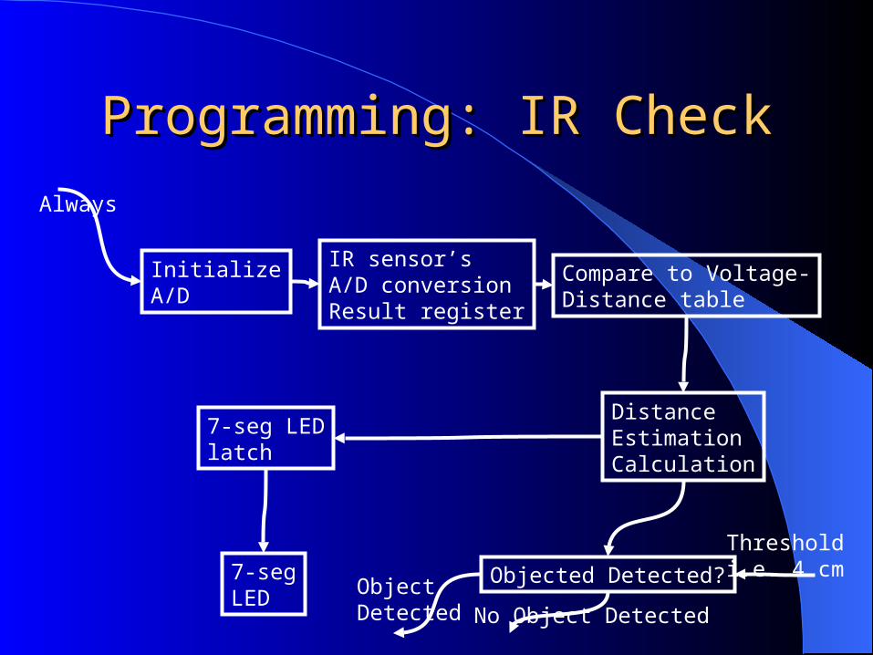
Programming: IR CheckProgramming: IR Check
InitializeA/D
IR sensor’sA/D conversionResult register
Compare to Voltage-Distance table
DistanceEstimationCalculation
7-seg LEDlatch
7-segLED
Objected Detected?
Always
Thresholdi.e. 4 cm
ObjectDetected No Object Detected
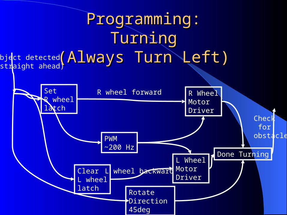
Programming:Programming:TurningTurning
(Always Turn Left)(Always Turn Left)
SetR wheellatch
ClearL wheellatch
PWM~200 Hz
R WheelMotorDriver
L WheelMotorDriver
RotateDirection 45deg
Done Turning
Object detected(straight ahead)
R wheel forward
L wheel backward
Check for obstacle
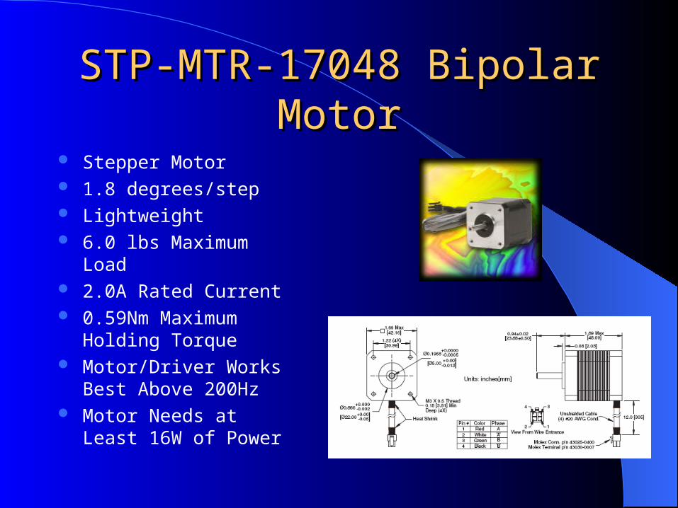
STP-MTR-17048 Bipolar STP-MTR-17048 Bipolar MotorMotor
Stepper Motor 1.8 degrees/step Lightweight 6.0 lbs Maximum Load 2.0A Rated Current 0.59Nm Maximum
Holding Torque Motor/Driver Works Best
Above 200Hz Motor Needs at Least 16W
of Power
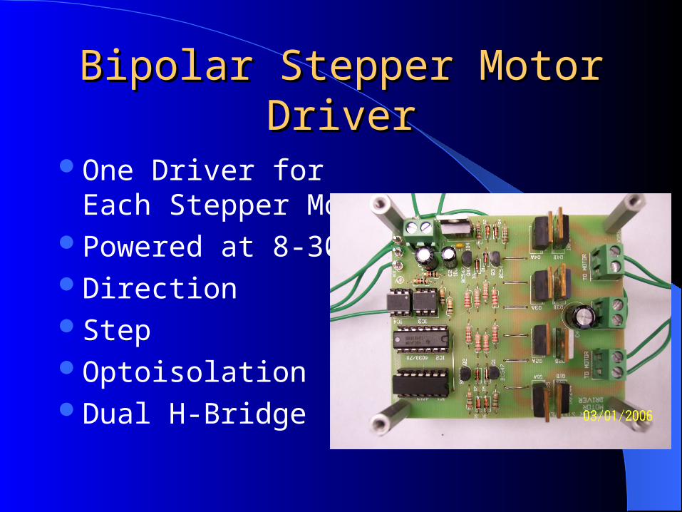
Bipolar Stepper Motor Bipolar Stepper Motor DriverDriver
One Driver for Each Stepper Motor
Powered at 8-30VDirectionStepOptoisolationDual H-Bridge
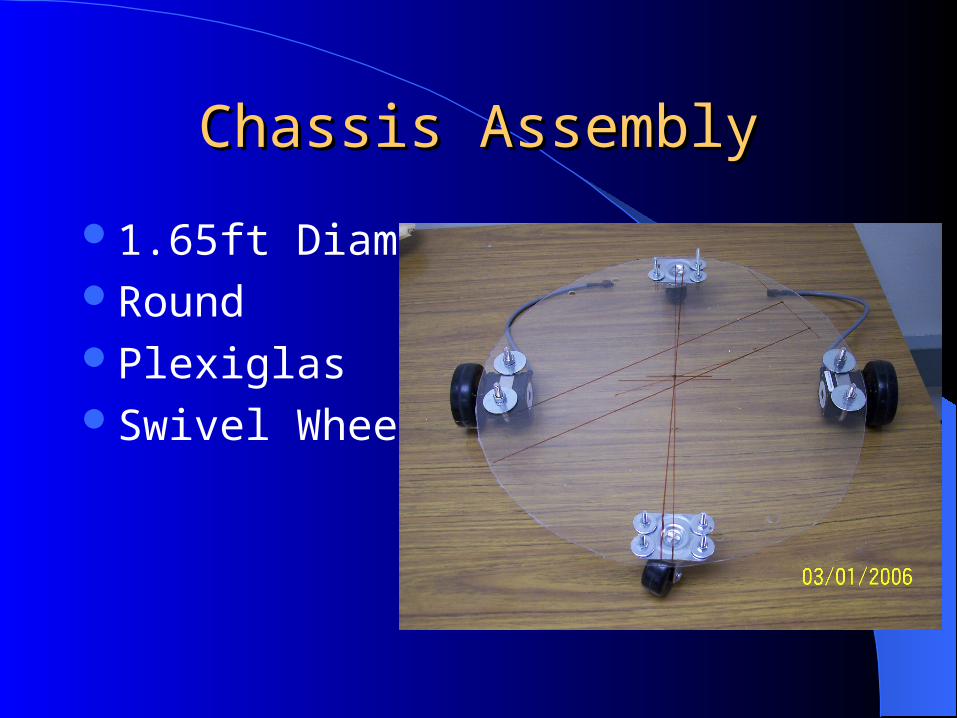
Chassis AssemblyChassis Assembly
1.65ft Diameter RoundPlexiglasSwivel Wheels
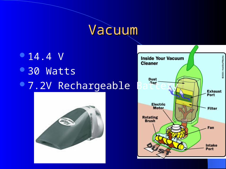
VacuumVacuum
14.4 V30 Watts7.2V Rechargeable Battery
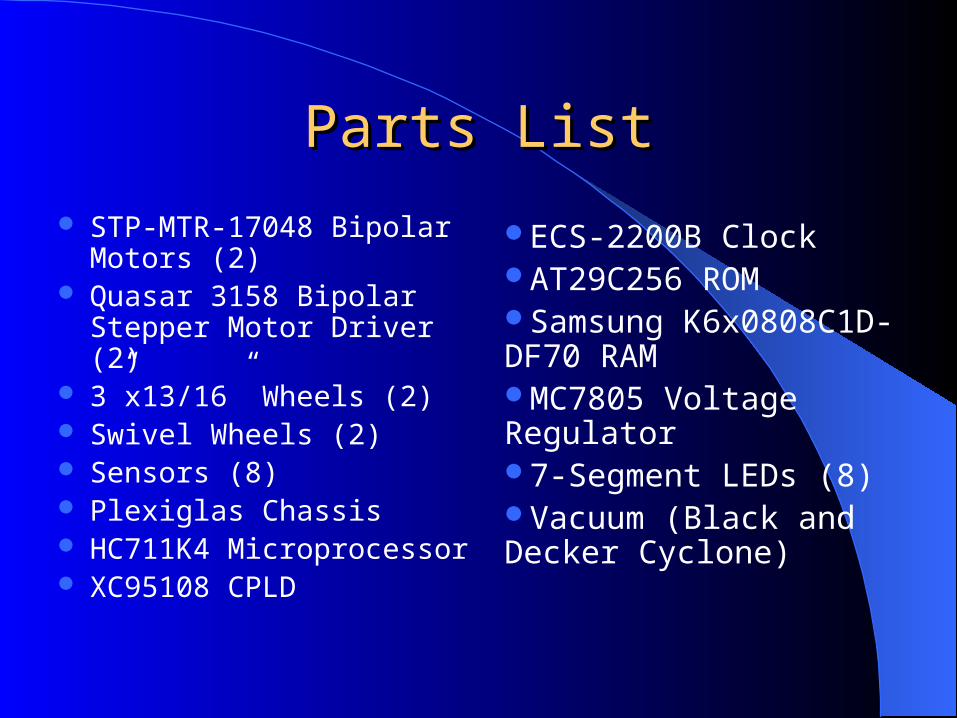
Parts ListParts List
STP-MTR-17048 Bipolar Motors (2)
Quasar 3158 Bipolar Stepper Motor Driver (2)
3”x13/16” Wheels (2) Swivel Wheels (2) Sensors (8) Plexiglas Chassis HC711K4 Microprocessor XC95108 CPLD
ECS-2200B ClockAT29C256 ROMSamsung K6x0808C1D-DF70 RAMMC7805 Voltage Regulator7-Segment LEDs (8)Vacuum (Black and Decker Cyclone)
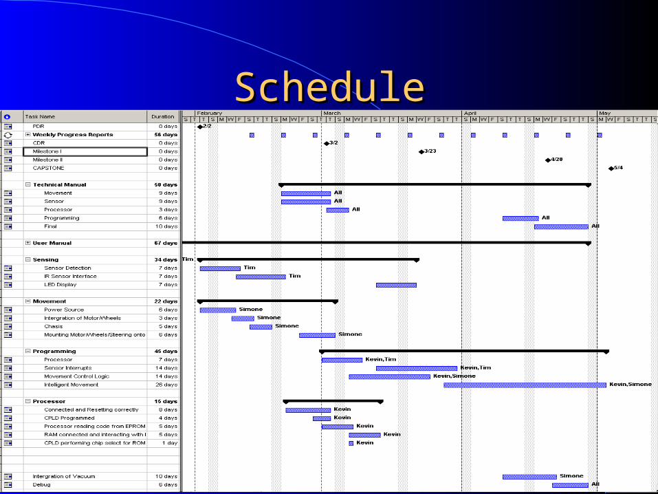
ScheduleSchedule
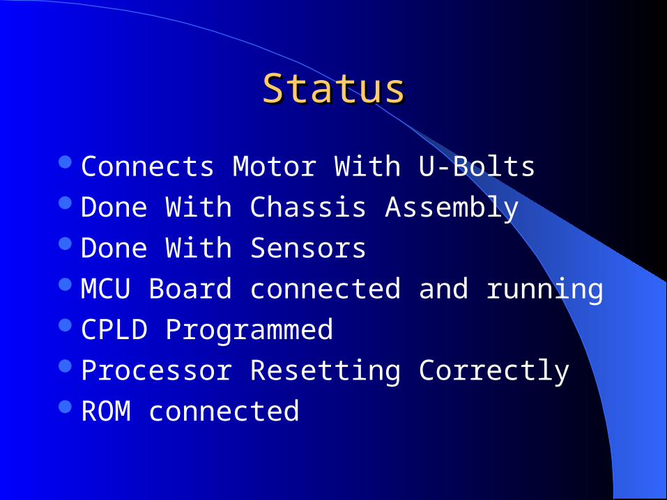
StatusStatus
Connects Motor With U-BoltsDone With Chassis AssemblyDone With SensorsMCU Board connected and runningCPLD ProgrammedProcessor Resetting CorrectlyROM connected
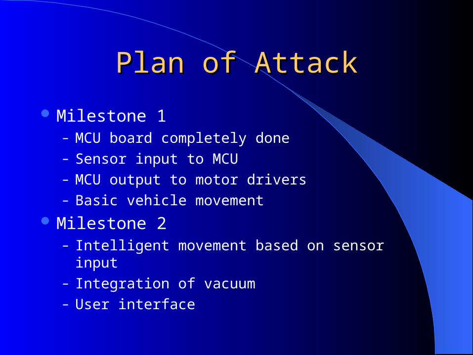
Plan of AttackPlan of Attack
Milestone 1– MCU board completely done– Sensor input to MCU– MCU output to motor drivers– Basic vehicle movement
Milestone 2– Intelligent movement based on sensor input– Integration of vacuum– User interface
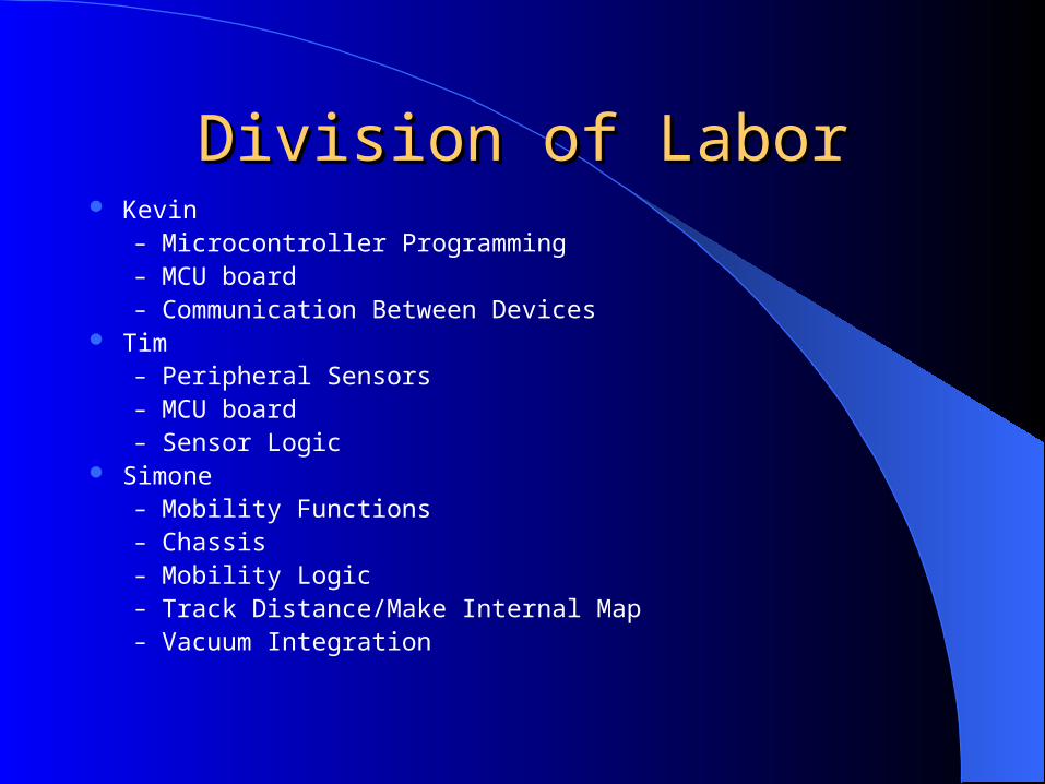
Division of LaborDivision of Labor Kevin
– Microcontroller Programming– MCU board– Communication Between Devices
Tim – Peripheral Sensors– MCU board– Sensor Logic
Simone – Mobility Functions– Chassis– Mobility Logic– Track Distance/Make Internal Map– Vacuum Integration
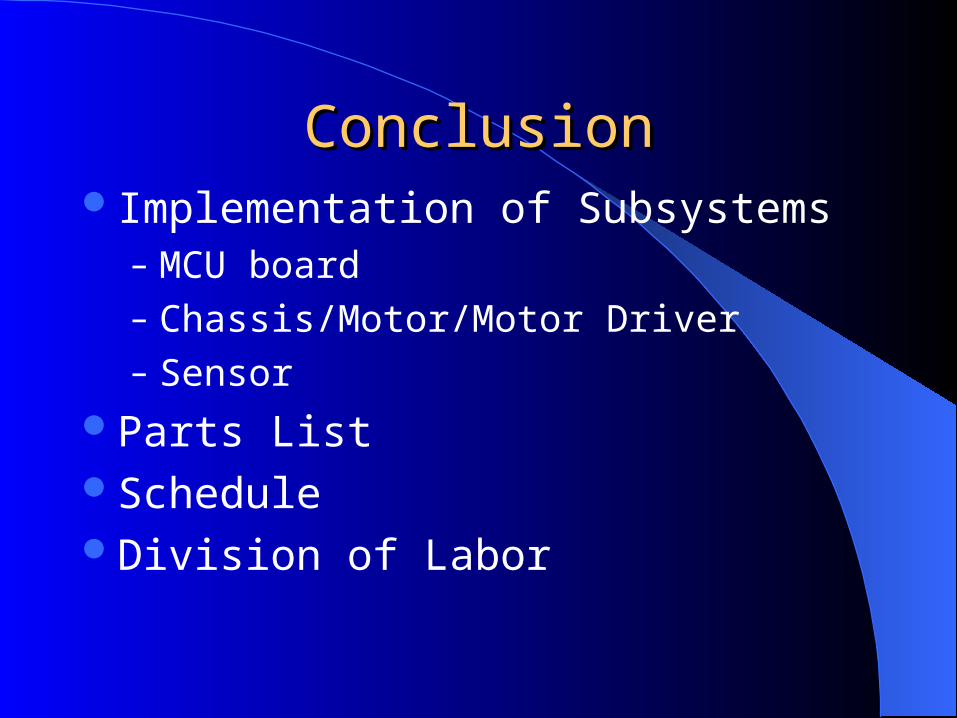
ConclusionConclusionImplementation of Subsystems
– MCU board– Chassis/Motor/Motor Driver– Sensor
Parts ListScheduleDivision of Labor