Embed Size (px)
Citation preview

Team Dominate(d?)
The Machine

Synopsis
Motorcycles are complex systems, containing many variables beyond what is displayed by standard gauges or rider intuition.
Understanding of these variables becomes more important in racing situations, where slight changes can significantly alter outcomes.
Our goal is to digitally characterize some of these variables, transmit information to an acquisition system, and then interpret them in order to improve motorcycle development and riding techniques.
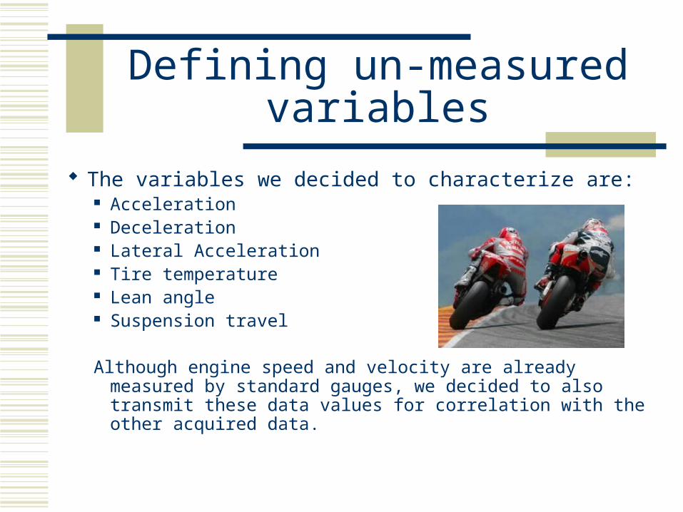
Defining un-measured variables
The variables we decided to characterize are: Acceleration Deceleration Lateral Acceleration Tire temperature Lean angle Suspension travel
Although engine speed and velocity are already measured by standard gauges, we decided to also transmit these data values for correlation with the other acquired data.

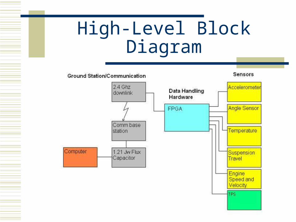
High-Level Block Diagram

Subsystem specifics: Sensors
Accelerometer LIS3LV02DQ 3 Axis Accelerometer
Cost ~ $40Digital Output- SPI or I2C digital interface+/- 2g acceleration rangeSmall size (21x23mm)3V power

Subsystem specifics: Sensors
Preferred Accelerometer/Inertial Measurement IMU 5
Cost ~ $110 Combines 3 axis accelerometer and angle sensor (gyros) Senses Roll and Pitch (Lean angle & wheelie) Senses Acceleration in X, Y, Z axes +/- 3g acceleration range Small size (20x23mm) Analog Output from IMU 3V Power
Subsystem specifics: Sensors
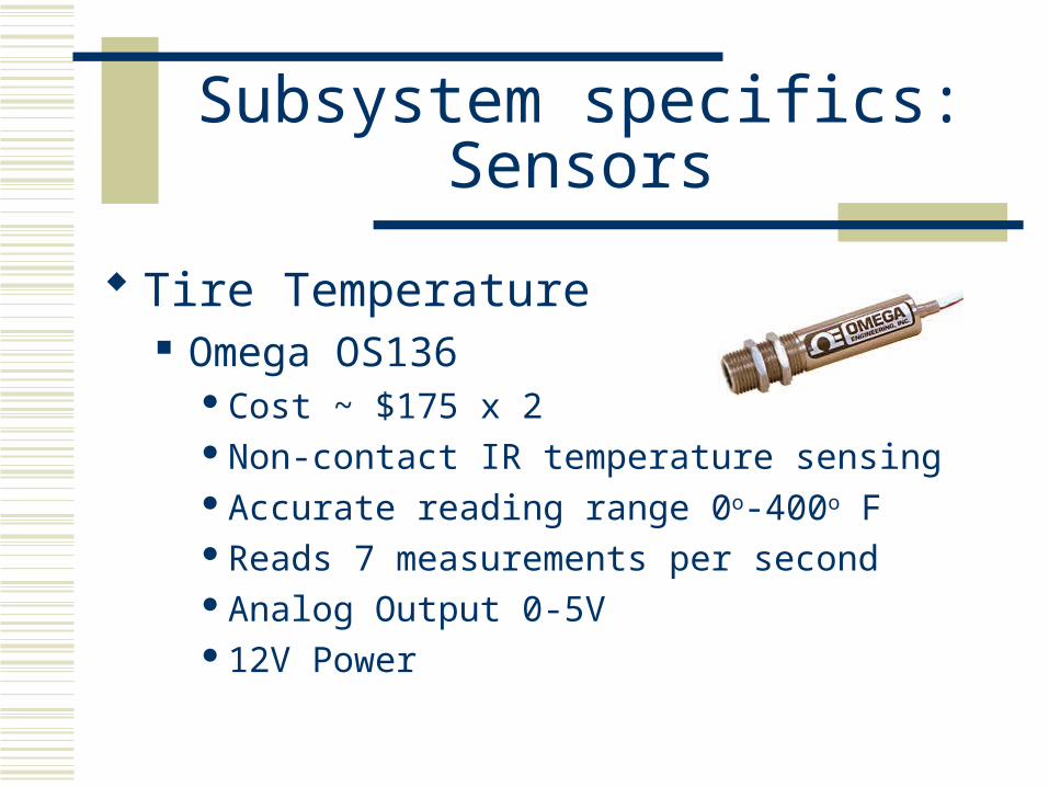
Tire Temperature Omega OS136
Cost ~ $175 x 2Non-contact IR temperature sensingAccurate reading range 0o-400o FReads 7 measurements per secondAnalog Output 0-5V12V Power

Subsystem specifics: Sensors
Suspension Travel Sharp IR proximity sensor
Cost ~ $12 x 2Measures distance between
fender and fixed mountedpoint of sensor
Analog output 3.1V @ 10cm, 0.4V @ 80cm
High-Level Block Diagram

Subsystem specifics: Sensors
Engine Speed/Velocity/Throttle Position/Gear Indicator OEM sensors/data decoders – <$100 Engine Speed/Velocity Sensor Output
Pulse signal - frequencies proportional to speed Throttle Sensor Output
Analog output linear with increasing throttle Gear Indicator
A known engine speed and velocity can be used to calculate the current gear selection
Not accurate while clutch is disengaged Only inaccurate during small fractions of time in race situations.

Subsystem Specifics: Sensor Communication
•Analog to Digital Converter
•Digital signal transmitted over I2C
•Signal received and processed by Data Handling Unit
•Transmit digital signal for superior quality over analog
•Data latches to hold values until next reading from sensor

Power
Power will be derived from the 12 volt DC motorcycle battery
Centrally located step down converters will adjust power to 5 and 3 volt supply.
A power filter and step down converters will be located on a circuit board near the Data handler

Subsystem Specifics: Data Handling
FPGA Prototype Board I2C Data Inputs RS232 Output Multiplexing ability for sensor selection Soft Core processor emulation

High-Level Block Diagram

Subsystem Specifics: Data Transmission
RF downlink Xbee-Pro wireless modem
RS-232 serial input for downlink communicationUSB interface to computer base station2.4 GHz, 115200 bps100 mW transmit power1 mile range line of sight12 channels

Software
We will use Visual C++ for the computer base station
Advising from Professor John Hauser (Motorcycle Dynamics Control)
Verilog code for bus controller and communication with the data handler
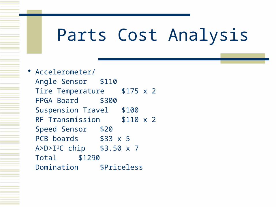
Parts Cost Analysis
Accelerometer/Angle Sensor $110Tire Temperature $175 x 2FPGA Board $300Suspension Travel $100RF Transmission $110 x 2Speed Sensor $20PCB boards $33 x 5A>D>I2C chip $3.50 x 7Total $1290Domination $Priceless

Division of Labor
Accelerometer /Bank Angle Sensor (Mr. Keogh and Mr. Pearse) Acquire data Transmit I2C Determine appropriate range for data
Data Handler (Mr.Olson and Mr. OConnell) Read I2C data Process data Transmit via RS232
Software (Mr.Schreiner) Read data from USB input Convert data to standard units Display data on computer

Risks
Extreme temperature from exhaust and engine
Engine and road vibration Physical damage from debris and crash Intricate Dynamics of motion too complex
for sensors or analysis
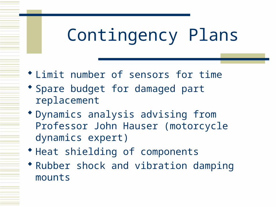
Contingency Plans
Limit number of sensors for time Spare budget for damaged part replacement Dynamics analysis advising from Professor
John Hauser (motorcycle dynamics expert) Heat shielding of components Rubber shock and vibration damping mounts


High-Level Block Diagram

Questions??