Embed Size (px)
Citation preview
The Physics Teacher ◆ Vol. 48, April 2010 217
Teaching the Fundamentals of Cell Phones and Wireless CommunicationsMark Davids, Grosse Pointe South H.S., Grosse Pointe Farms, MIRick Forrest, Rochester H.S., Rochester, MIDon Pata, Grosse Pointe North H.S., Grosse Pointe Farms, MI
Wireless communications are ubiquitous. Students and teachers use iPhones®, BlackBerrys®, and other smart phones at home and at work. More
than 275 million Americans had cell phones in June of 20091 and expanded access to broadband is predicted this year.2 Despite the plethora of users, most students and teachers do not understand “how they work.” Over the past several years, three high school teachers have collaborated with engineers at Cingular, Motorola, and the University of Michigan to explore the underlying science and design a three-week, student-centered unit with a constructivist pedagogy consistent with the “Modeling in Physics” philosophy.3 This unique pilot pro-gram reinforces traditional physics topics including vibrations and waves, sound, light, electricity and magnetism, and also introduces key concepts in communications and information theory. This article will describe the motivation for our work, outline a few key concepts with the corresponding student ac-tivities, and provide a summary of the program that has been developed to engage and inspire the next generation of scien-tists, engineers, and citizens.
Even the longest journey …Most research begins with questions. Several of our stu-
dents had posed questions about cell phones and we were hard pressed for answers. Even when we shared the questions with our colleagues at our DMAPT4 meetings, we were uncertain of the answers to basic questions such as: How do the compa-nies know your location? How do cell phones keep conversations private? Are cell phones safe? and Why can’t you use cell phones when flying in airplanes? We have presented at national AAPT and NSTA conferences from California to New York, and we have found that physics teachers have the same questions as our students. We realized that many of these questions were more about technology and engineering, but we were confi-dent that they involved applications of fundamental physics principles. We fully expected that others had asked these same questions and had already developed a curriculum around wireless communications; however, when we contacted the AAPT and NSTA, we found that there was no known cur-riculum around this topic. Placing notices on the PTRA5 and Modeling in Physics networks yielded the same disappointing result.
Making connectionsBefore students can understand and appreciate the sophis-
ticated technology that goes into their communications devic-es, they need to understand the underlying physics, beginning
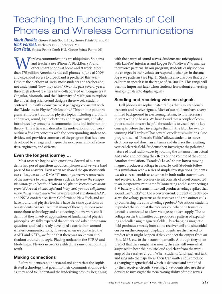
with the nature of sound waves. Students use microphones with LabPro® interfaces and Logger Pro® software6 to analyze their voice patterns. In our program, students easily see how the changes in their voices correspond to changes in the ana-log wave patterns (see Fig. 1). Students also discover that typi-cal human speech is in the range of 20-500 Hz. This range will become important later when students learn about converting analog signals into digital signals.
Sending and receiving wireless signalsCell phones are sophisticated radios that simultaneously
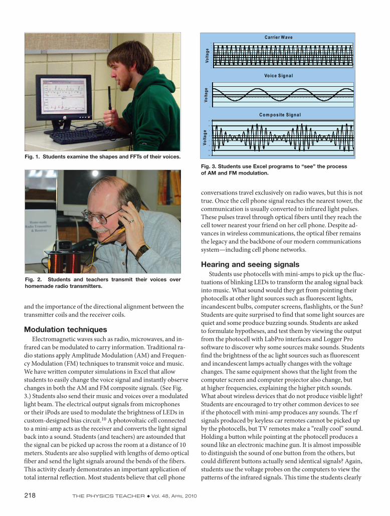
transmit and receive signals. Most of our students have a very limited background in electromagnetism, so it is necessary to start with the basics. We have found that a couple of com-puter simulations are helpful for students to visualize the key concepts before they investigate them in the lab. The award-winning PhET website7 has several excellent simulations. One program, called “Electric Fields,” allows students to move electrons up and down an antenna and displays the resulting vertical electric field. Students then investigate the polarized nature of local radio waves by rotating the antenna of an actual AM radio and noticing the effects on the volume of the sound. Another simulation, “Faraday’s Laws,” shows how a moving magnet produces a voltage in a nearby coil. Students follow this simulation with a series of simple investigations. Students use air core solenoids as antennas in both radio transmitters and receivers. The receiver circuit consists of a coil connected to an inexpensive mini-amp.8 Connecting and disconnecting a 9-V battery to the transmitter coil produces voltage spikes that sound like “clicks” on the receiver circuit. Students directly ob-serve the voltage patterns at the receiver and transmitter coils by connecting the coils to voltage probes.9 We ask our students to predict the sound at the receiver coil when the transmit-ter coil is connected to a low-voltage ac power supply. The ac voltage on the transmitter coil produces a pattern of expand-ing and collapsing magnetic fields. This changing magnetic field produces a steady hum at the receiver coil and sinusoidal curves on the computer display. Students are then asked to predict what might happen if they connect the output from an iPod, MP3, etc. to their transmitter coils. Although they often predict that they might hear music, they are still somewhat surprised to hear their music loud and clear from the mini-amp of the receiver circuit. When students (and teachers) talk and sing into their speakers, their transmitter coils produce a changing magnetic field which is detected and amplified by their receiver circuits. (See Fig. 2.) Students also use these devices to investigate the penetrating ability of these waves
218 The Physics Teacher ◆ Vol. 48, April 2010
and the importance of the directional alignment between the transmitter coils and the receiver coils.
Modulation techniquesElectromagnetic waves such as radio, microwaves, and in-
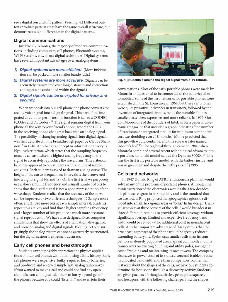
frared can be modulated to carry information. Traditional ra-dio stations apply Amplitude Modulation (AM) and Frequen-cy Modulation (FM) techniques to transmit voice and music. We have written computer simulations in Excel that allow students to easily change the voice signal and instantly observe changes in both the AM and FM composite signals. (See Fig. 3.) Students also send their music and voices over a modulated light beam. The electrical output signals from microphones or their iPods are used to modulate the brightness of LEDs in custom-designed bias circuit.10 A photovoltaic cell connected to a mini-amp acts as the receiver and converts the light signal back into a sound. Students (and teachers) are astounded that the signal can be picked up across the room at a distance of 10 meters. Students are also supplied with lengths of demo optical fiber and send the light signals around the bends of the fibers. This activity clearly demonstrates an important application of total internal reflection. Most students believe that cell phone
conversations travel exclusively on radio waves, but this is not true. Once the cell phone signal reaches the nearest tower, the communication is usually converted to infrared light pulses. These pulses travel through optical fibers until they reach the cell tower nearest your friend on her cell phone. Despite ad-vances in wireless communications, the optical fiber remains the legacy and the backbone of our modern communications system—including cell phone networks.
Hearing and seeing signalsStudents use photocells with mini-amps to pick up the fluc-
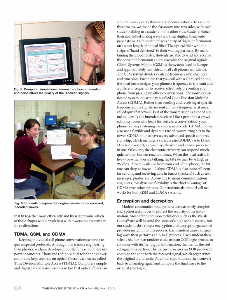
tuations of blinking LEDs to transform the analog signal back into music. What sound would they get from pointing their photocells at other light sources such as fluorescent lights, incandescent bulbs, computer screens, flashlights, or the Sun? Students are quite surprised to find that some light sources are quiet and some produce buzzing sounds. Students are asked to formulate hypotheses, and test them by viewing the output from the photocell with LabPro interfaces and Logger Pro software to discover why some sources make sounds. Students find the brightness of the ac light sources such as fluorescent and incandescent lamps actually changes with the voltage changes. The same equipment shows that the light from the computer screen and computer projector also change, but at higher frequencies, explaining the higher pitch sounds. What about wireless devices that do not produce visible light? Students are encouraged to try other common devices to see if the photocell with mini-amp produces any sounds. The rf signals produced by keyless car remotes cannot be picked up by the photocells, but TV remotes make a “really cool” sound. Holding a button while pointing at the photocell produces a sound like an electronic machine gun. It is almost impossible to distinguish the sound of one button from the others, but could different buttons actually send identical signals? Again, students use the voltage probes on the computers to view the patterns of the infrared signals. This time the students clearly
Fig. 1. Students examine the shapes and FFTs of their voices.
Fig. 2. Students and teachers transmit their voices over homemade radio transmitters.
-18
-13
-8
-3
2
7
12
17
1 10 19 28 37 46 55 64 73 82 91 100 109 118 127 136 145 154 163 172 181 190 199 208 217 226 235 244 253 262 271 280 289 298 307 316 325 334 343 352 361 370 379 388 397 406 415 424 433 442 451 460 469 478 487 496
Volta
ge
C o m p o s ite S ig n a l
-12
-7
-2
3
8
1 11 21 31 41 51 61 71 81 91 101 111 121 131 141 151 161 171 181 191 201 211 221 231 241 251 261 271 281 291 301 311 321 331 341 351 361 371 381 391 401 411 421 431 441 451 461 471 481 491
Volta
ge
Vo ic e S ig n a l
-10
-8
-6
-4
-2
0
2
4
6
8
10
1 11 21 31 41 51 61 71 81 91 101 111 121 131 141 151 161 171 181 191 201 211 221 231 241 251 261 271 281 291 301 311 321 331 341 351 361 371 381 391 401 411 421 431 441 451 461 471 481 491
Volta
ge
Carrier W ave
Fig. 3. Students use Excel programs to “see” the process of AM and FM modulation.
The Physics Teacher ◆ Vol. 48, April 2010 219
see a digital (on and off) pattern. (See Fig. 4.) Different but-tons produce patterns that have the same overall structure, but demonstrate slight differences in the digital patterns.
Digital communicationsJust like TV remotes, the majority of modern communica-
tions, including computers, cell phones, Bluetooth systems, Wi-Fi systems, etc., all use digital techniques. Digital systems have several important advantages over analog systems:
1) Digital systems are more efficient. (More informa-tion can be packed into a smaller bandwidth.)
2) Digital systems are more accurate. (Signals can be accurately transmitted over long distances and correction coding can be embedded within the signal.)
3) Digital signals can be encrypted for privacy and security.
When we speak into our cell phone, the phone converts the analog voice signal into a digital signal. This part of the inte-grated circuit that performs this function is called a CODEC (COder and DECoder).11 The signal remains digital from your phone all the way to your friend’s phone, where the CODEC in the receiving phone changes it back into an analog signal. The possibility of changing analog signals into digital signals was first described in the breakthrough paper by Claude Shan-non12 in 1948. Another key concept in information theory is Nyquest’s criterion, which states that the sampling frequency must be at least twice the highest analog frequency of the signal to accurately reproduce the waveforms. This criterion becomes apparent to our students with a couple of simple activities. Each student is asked to draw an analog curve. The height of the curve at equal time intervals is then converted into a digital signal (0s and 1s). On the first trial we purposely use a slow sampling frequency and a small number of bits to show that the digital signal is not a good representation of the wave shape. Students realize that the accuracy of the curve can be improved by two different techniques: 1) Sample more often, and 2) Use more bits at each sample interval. Students repeat this activity and find that a higher sampling frequency and a larger number of bits produce a much more accurate signal reproduction. We have also designed Excel computer simulations that show the effects of attenuation, divergence, and noise on analog and digital signals. (See Fig. 5.) Not sur-prisingly, the analog system cannot be accurately regenerated, but the digital system is extremely accurate.
Early cell phones and breakthroughsStudents cannot possibly appreciate the physics applica-
tions of their cell phones without knowing a little history. Early cell phones were expensive, bulky, required heavy batteries, and produced and received simple AM analog radio waves. If you wanted to make a call and could not find any open channels, you could just ask others to hurry up and get off the phones because you could “listen in” and even join their
conversations. Most of the early portable phones were made by Motorola and designed to be connected to the batteries of au-tomobiles. Some of the first networks for portable phones were established in the St. Louis area in 1964, but these car phones were quite primitive. Advances in transistors, followed by the invention of integrated circuits, made the portable phones smaller, faster, less expensive, and more reliable. In 1965, Gor-don Moore, one of the founders of Intel, wrote a paper in Elec-tronics magazine that included a graph indicating “the number of transistors on integrated circuits for minimum component cost was doubling every 18 months.” Moore predicted that this growth would continue, and this rule was later named “Moore’s law.”13 The big breakthrough came in 1984, when Motorola combined several recent technological advances into a portable, handheld model named the Dynatac 8000X.14 This was the first truly portable model (with the battery inside) and was in great demand despite the hefty price of $3995.
Cells and networksIn 1947 Donald Ring of AT&T envisioned a plan that would
solve many of the problems of portable phones. Although the miniaturization of the electronics would take a few decades, his plan was elegant in its simplicity and is the standard that we use today: Ring proposed that geographic regions be di-vided into small, hexagonal areas or “cells.” In his design, trian-gular towers at three corners of the cells15 would broadcast in three different directions to provide efficient coverage without significant overlap. Limited and expensive frequency band-width could be reused (at no additional cost) in nonadjacent cells. Another important advantage of this system is that the broadcasting power of the phone would be greatly reduced, extending battery life. Sprint uses smaller cells than its com-petitors in densely populated areas. Sprint commonly mounts transceivers on existing building and utility poles, saving the cost of building and maintaining its own towers. The company also saves in power costs of its transceivers and is able to reuse its allocated bandwidth more than competitors. Rather than just read about the shapes of the cells, we have our students de-termine the best shape through a discovery activity. Students are given packets of triangles, circles, pentagons, squares, and hexagons with the following challenge: Find the shapes
Fig. 4. Students examine the digital signal from a TV remote.
220 The Physics Teacher ◆ Vol. 48, April 2010
that fit together most efficiently and then determine which of these shapes would work best with towers that transmit in three directions.
TDMA, GSM, and CDMAKeeping individual cell phone conversations separate re-
quires special protocols. Although this is more engineering than physics, we have developed models for each of these im-portant concepts. Thousands of individual telephone conver-sations are kept separate on optical fibers by a process called Time Division Multiple Access (TDMA). Computers sample and digitize voice transmissions so fast that optical fibers can
simultaneously carry thousands of conversations. To explore this process, we divide the classroom into two sides, with each student talking to a student on the other side. Students sketch their individual analog waves and then digitize them onto paper strips. Each student places a strip of digital information on a short length of optical fiber. The optical fiber with the strips is “hand delivered” to their waiting partners. By main-taining the proper order, students are able to send and receive the correct information and reassemble the original signals. Global Systems Mobile (GSM) is the system used in Europe and approximately two-thirds of all cell phones worldwide. The GSM system divides available frequency into channels and time slots. Each time that you call with a GSM cell phone, the local tower assigns your phone a frequency to transmit and a different frequency to receive, effectively preventing your phone from picking up other conversations. The most sophis-ticated system in use today is called Code Division Multiple Access (CDMA). Rather than sending and receiving at specific frequencies, the signals are sent at many frequencies at once, called spread spectrum. Part of the transmission is a coded sig-nal to identify the intended receiver. Like a person in a crowd-ed, noisy room who hears his voice in a conversation, your phone is always listening for your special code. CDMA phones also use a flexible and dynamic rate of transmitting bits to the tower. CDMA phones have a very advanced speech compres-sion chip, which includes a variable rate CODEC (A to D and D to A converter), a speech synthesizer, and a voice processor in one. Of course, the electronic circuitry can respond much quicker than human reaction times. When the local traffic is heavy or when you are talking, the bit rate may be as high as 96 kbps. If there is silence from your end of the phone, the bit rate can drop as low as 1.2 kbps. CDMA is also more efficient for sending and receiving data in bursts (packets) such as text messages, photos, etc. According to many communications engineers, this dynamic flexibility is the chief advantage of CDMA over other systems. Our students also model cell net-works for both GSM and CDMA systems.
Encryption and decryptionModern communications systems use extremely complex
encryption techniques to protect the security of the infor-mation. Most of the common techniques such as the Walsh Codes16 are well beyond the scope of a high school course, but our students do a simple encryption and decryption game that provides insight into this process. Each student draws an ana-log wave then performs an A to D process. Each student then selects his/her own random code, uses an XOR logic process to combine with his/her digital information, then sends the cod-ed signal to a partner. The partner also uses an XOR process to combine the code with the received signal, which regenerates the original digital code. As a final step, students then convert back to an analog signal and compare the final wave to the original (see Fig. 6).
Fig. 5. Computer simulations demonstrate how attenuation and noise affect the quality of the received signals.
Fig. 6. Students compare the original waves to the received, decoded waves.
The Physics Teacher ◆ Vol. 48, April 2010 221
Our partners
Fortunately, everyone we approached about the project was enthusiastic and supportive. We received initial funding from the National Education Association17 and the Convergence Education Foundation (CEF).18 Engineers at Cingular, Mo-torola, and the University of Michigan also met with our team to provide insights and answer our technical questions. In the summer of 2006 Yazaki North America19 hosted a workshop that drew teachers from five states. We have also enlisted local experts to make presentations to our students. These experts have included a technical writer for The New York Times, an engineer from Sprint, and the father of OnStar®, Dave Acton.20 Acton also shared his current passion—designing wireless communications systems to prevent auto accidents.
Project summaryDuring the summer of 2004, we learned the basics of mod-
ern communications systems and developed a number of unique student activities so that students could answer most of their own questions. In the school year 2004-2005, we piloted the material at four local high schools. We were pleasantly surprised at the enthusiastic response from our students. We did some revisions over the summer of 2005 and presented at a few teacher conferences. Another grant from CEF and a coun-ty school agency provided the funding to give two full days of training for 30 teachers. At the end of the training, the teachers had full use of the student kits.21 The overwhelmingly posi-tive response from the teachers and the CEF has allowed us to provide both the training and the equipment over the past four summers. To date we have trained more than 100 teach-ers from seven states who have shared the program with about 26,000 students. We plan on having another training session this summer and are seeking a sponsor to allow the program to continue to grow.
AcknowledgmentsWe are grateful to Paul Zitzewitz, who provided valuable insights, specific suggestions, and encouragement and sup-port for improving the program. The CEF, now Square One Education Network, has provided funding for most of the costs of the equipment and teacher workshops.
References1. CTIA The Wireless Industry report. Visit www.ctia.org/media/
industry_info/index.cfm/AID/10323.2. Michael Moyer, “Bigger better broadband,” Sci. Am. 302 (2), 26
(Feb. 2010).3. The Modeling in Physics program has trained hundreds of
physics teachers in researched-based, constructivist pedagogy. See modeling.asu.edu.
4. The Detroit Metropolitan Area Physics Teachers (DMAPT) has provided sharing opportunities for high school and university physics teachers since 1958. The DMAPT has about 50 active members and became and affiliate member of the AAPT in 1984. See www.dmaptphysics.com/PhysicsLinks.html.
5. The Physics Teaching Resource Agents (PTRA) program has trained hundreds of teachers, starting in 1985. See www.aapt.org/ptra.
6. LabPro and Logger Pro are trademarks of Vernier Software and Technology; www.vernier.com.
7. The Physics Group at the University of Colorado has an excel-lent collection of simulations. See PhET.colorado.edu/web-pages/simulations-base.html.
8. The mini-amp is a combination amplifier-speaker available from Radio Shack, part #277-1008, for about $14 each. See www.Radioshack.com.
9. The voltage probes are supplied as part of the Vernier’s LabPro® package.
10. The bias circuit is now available from Arbor Scientific Com-pany; www.arborsci.com.
11. Andy Dornan, The Essential Guide to Wireless Communications, 2nd ed., (Prentice Hall, May 2002) is an exceptionally useful pa-per reference.
12. Claude Shannon, “A mathematical theory of communication,” Bell System Tech. J., available online at: cm.bell-labs.com/cm/ms/what/shannonday/paper.html.
13. This website includes a thorough history of the various forms of Moore’s law: www.firstmonday.org/issues/issue7_11/tuomi/.
14. Stewart Wolpin, “Hold the phone,” Invent. Discov. 21-31 (Winter 2007).15. Tom Farley, “The cell phone,” Invent. Discov. 8-19 (Winter
2007). Also see his exceptional website: privateline.com. 16. To learn more about Walsh-Hadamard codes, see: mathworks.
com/access/helpdesk/help/toolbox/commblks/ref/walshcode-generator.html.
17. The NEA Learning and Leadership grant has been replaced by the Fund for Teachers grant. See www.nea.org/grants/fft07.html.
18. CEF is now the Square One Education Network. The founda-tion is a robust organization of engineers who promote science, engineering, and technology programs for youth. See: www.squareonenetwork.org.
19. Yazaki is a major supplier of automotive components. See www.yazaki-na.com/.
20. Dave Acton is a visionary engineer and entrepreneur. He is also the retired director of Global Telematics for General Motors. 21. After two full days of training, teachers are loaned the class-
room kits. Each kit contains all of the equipment needed for the program, including AM radios, two-way radios, speakers, laser pointers, photovoltaic cells, mini-amps, optical fibers, bias circuits, resonance devices, custom shapes, bar code kits, CD of our software programs and computer simulations, Andy Dor-nan’s book, etc.
Mark Davids, Rick Forrest, and Don Pata are active in the Detroit Metro Area Physics Teachers and the Michigan Section of the AAPT. Davids and Pata are also leaders in the Modeling in Physics pedagogy. Davids has authored or coauthored several works and was selected for the AAPT’s Excellence in Pre-College Physics Teaching Award in [email protected], [email protected], [email protected]


![[B. Baumslag.] Fundamentals of Teaching Mathematics](https://img.pdfslide.us/doc/110x75/55cf98a8550346d03398ed7b/b-baumslag-fundamentals-of-teaching-mathematics.jpg)