Embed Size (px)
Citation preview
2017 ASEE Zone II Conference
© American Society for Engineering Education, 2017
Teaching Industry Relevant and Application Oriented Skills in
Automation and Control by Developing State-of-the-Art
Integrated Robotic Workcell
S. Parmar, A. Sergeyev, and N. Alaraje Michigan Technological University
Abstract
There is an increasing demand for automation in the industry due to expensive manual labor and
faster manufacturing processes. Therefore, there is a need to educate future engineers in relevant
to current industry needs automated systems which generally consist of Programmable Logic
Controllers (PLCs), industrial robots, conveyors, pneumatic, various sensors and vision systems.
Objective of this project is to develop an integrated work cell using 6-axis FANUC robots, PLCs,
Conveyor, Sensors, pneumatics and vision systems for academic curriculum bridging the gap
between industry and educational institution by teaching rapidly emerging technologies. The
developed system provide the students with an opportunity to develop real time scenarios in
material handling applications similar pick and place parts moving on a conveyor using sensors
and vision systems, end-effector tools, hand shaking of two 6-axis robots and controlled by PLC.
Training engineering professionals and testing them on different applications using a single work
cell will help them to develop a holistic approach towards solving real time solutions in the
automation industry. Presented in this paper work provides a detailed, state-of-the-art laboratory
setup that can be replicated by the other educational institutions demanding to expand in the field
of industrial automation and controls.
Keywords
Robotics, Control, PLC, and Robotic Education
Robotic Workcell Introduction
There has been a tremendous amount of growth in the worldwide sales of industrial robots. A
recent article published by International Federation of Robotics 1 apprises that a new record sale
of 248,000 units was set in 2015 which had an increment of 12% compared to 2014. Statistics
claim that by 2018, 2.3 million units will be installed in factories around the globe. Industrial
Automation is currently making a huge impact on the global economy. With the rapid growth in
the industrial automation sector, there is an increasing demand for trained robot engineers in the
market. Adam Stienecker (2008) stated 2, “Today, industry is much less in need of robot
designers and much more in need of experts in the application of robots and the design of the
systems that work with the robots such as end-of-arm-tooling and vision systems”. He rightly
highlights that the industry needs more system designers who have the knowledge to interface
multiple robots with vision systems, experience with PLC and are aware of different hardware
used alongside robots.
Imparting education to students using such laboratories and providing them the confidence to
tackle different applications or troubleshooting systems has been the driving force in developing
a robotic workcell for the robotics vision course at Michigan Technological University. The main
2017 ASEE Zone II Conference
© American Society for Engineering Education, 2017
objective of creating such a workcell is to give the students a closer view and a real-time
experience of the industrial setting and its applications. Developing an industry-like integrated
system to be used for academic curriculum greatly enhances the students’ knowledge in subject
matter, improves comprehension process, and provides them with a great exposure to the
industrial environment. The paper discusses in great detail all the components, equipment, and
wiring diagrams of the workcell such that anybody could replicate the workcell at their
respective institutions.
Existing Robotic Workcells
Companies such as ABB 3, FANUC America 4 and KUKA Robotics 5 have designed educational
robotic carts for hands on learning of certificate based robotic courses. High schools and
universities tie up with such robot manufacturers to setup an industrial automation laboratory at
their institutions. Most of these robots are mounted on a single cart and are built with certain
limitations that restrict the robot from being used for a variety of applications. Adam Stienecker
(2008) developed a workcell laboratory at the Ohio Northern University by procuring individual
robots from KUKA Robotics and setting up an integrated system with CNC machine, conveyor
and sensors 6. Dr. Arif Sirinterlikci’s (2015) team at Robert Morris University developed a vison
based sorting laboratory which consists of the FANUC robot’s vision system, a bowl feeder,
linear actuator and proximity sensors. The workcell was primarily created as a future learning
module for the robotics and automation course (ENGR 4700). William Ferry and Andrew Otieno
(2004) have designed and developed a low cost bottle capping automation system 7 consisting of
PLC, vision system and multiple DENSO robots with the purpose of teaching automation
integration of different hardware at Northern Illinois University.
Developed Integrated Robotic Workcell at Michigan Tech
The industrial automation laboratory at Michigan technological university has four FANUC
training carts, each comprising of a FANUC LR Mate 200iC robot, R-30iA Mate Controller,
Sony XC-56 camera, air supply and a computer. These robots have an option for interchangeable
end-effectors such as suction cups and 2-finger parallel grippers, which provides flexibility in
developing a variety of application scenarios for the laboratory exercises. Approach of
integrating three FANUC robots with a conveyor, programmable logic controller (PLC), safety
guards, through beam sensors and vision systems in a single integrated robotic workcell is
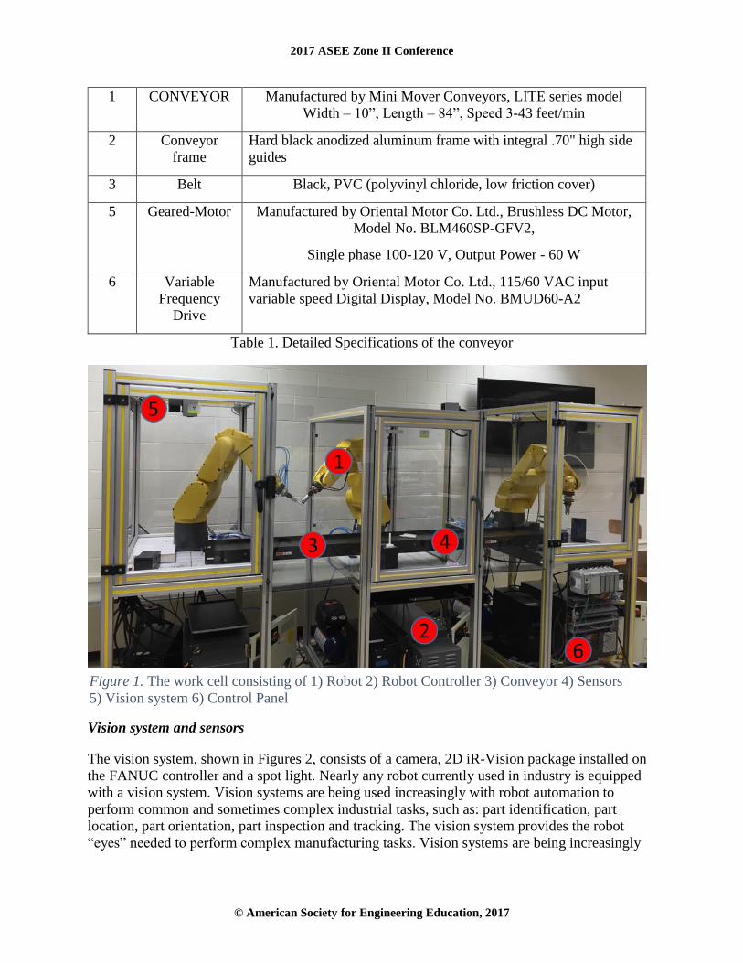
outlined in this paper. Figure 1 depicts the overall layout of the integrated robotic workcell.
Conveyor System
The conveyor system, shown in #3 of Figure 1, design was selected based on the various
functionalities that would be required to develop the industrial scenarios for the lab exercises of
the robotic vision course. The system conveys various products such as Jenga blocks, markers,
empty cups and pills. The conveyor 8 can either be run at four different speeds in forward
direction or at one constant speed in forward and reverse directions. The variable frequency drive
(VFD) mounted on the control panel provides an option for setting up the multiple speeds. The
specifications of the conveyor and its parts are shown in detail in Table 1.
S No. Specifications Description
2017 ASEE Zone II Conference
© American Society for Engineering Education, 2017
1 CONVEYOR Manufactured by Mini Mover Conveyors, LITE series model
Width – 10”, Length – 84”, Speed 3-43 feet/min
2 Conveyor
frame
Hard black anodized aluminum frame with integral .70" high side
guides
3 Belt Black, PVC (polyvinyl chloride, low friction cover)
5 Geared-Motor Manufactured by Oriental Motor Co. Ltd., Brushless DC Motor,
Model No. BLM460SP-GFV2,
Single phase 100-120 V, Output Power - 60 W
6 Variable
Frequency
Drive
Manufactured by Oriental Motor Co. Ltd., 115/60 VAC input
variable speed Digital Display, Model No. BMUD60-A2
Table 1. Detailed Specifications of the conveyor
Vision system and sensors
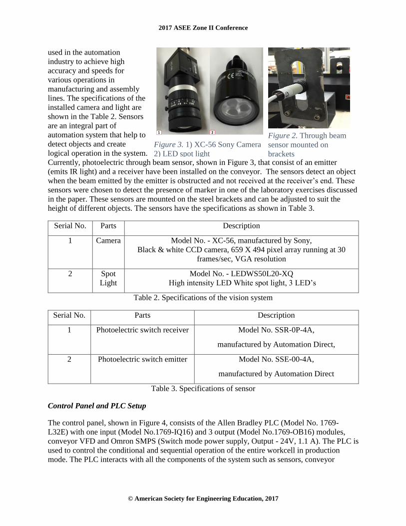
The vision system, shown in Figures 2, consists of a camera, 2D iR-Vision package installed on
the FANUC controller and a spot light. Nearly any robot currently used in industry is equipped
with a vision system. Vision systems are being used increasingly with robot automation to
perform common and sometimes complex industrial tasks, such as: part identification, part
location, part orientation, part inspection and tracking. The vision system provides the robot
“eyes” needed to perform complex manufacturing tasks. Vision systems are being increasingly
Figure 1. The work cell consisting of 1) Robot 2) Robot Controller 3) Conveyor 4) Sensors
5) Vision system 6) Control Panel
2017 ASEE Zone II Conference
© American Society for Engineering Education, 2017
used in the automation
industry to achieve high
accuracy and speeds for
various operations in
manufacturing and assembly
lines. The specifications of the
installed camera and light are
shown in the Table 2. Sensors
are an integral part of
automation system that help to
detect objects and create
logical operation in the system.
Currently, photoelectric through beam sensor, shown in Figure 3, that consist of an emitter
(emits IR light) and a receiver have been installed on the conveyor. The sensors detect an object
when the beam emitted by the emitter is obstructed and not received at the receiver’s end. These
sensors were chosen to detect the presence of marker in one of the laboratory exercises discussed
in the paper. These sensors are mounted on the steel brackets and can be adjusted to suit the
height of different objects. The sensors have the specifications as shown in Table 3.
Serial No. Parts Description
1 Camera Model No. - XC-56, manufactured by Sony,
Black & white CCD camera, 659 X 494 pixel array running at 30
frames/sec, VGA resolution
2 Spot
Light
Model No. - LEDWS50L20-XQ
High intensity LED White spot light, 3 LED’s
Table 2. Specifications of the vision system
Serial No. Parts Description
1 Photoelectric switch receiver Model No. SSR-0P-4A,
manufactured by Automation Direct,
2 Photoelectric switch emitter Model No. SSE-00-4A,
manufactured by Automation Direct
Table 3. Specifications of sensor
Control Panel and PLC Setup
The control panel, shown in Figure 4, consists of the Allen Bradley PLC (Model No. 1769-
L32E) with one input (Model No.1769-IQ16) and 3 output (Model No.1769-OB16) modules,
conveyor VFD and Omron SMPS (Switch mode power supply, Output - 24V, 1.1 A). The PLC is
used to control the conditional and sequential operation of the entire workcell in production
mode. The PLC interacts with all the components of the system such as sensors, conveyor
Figure 3. 1) XC-56 Sony Camera
2) LED spot light
Figure 2. Through beam
sensor mounted on
brackets

2017 ASEE Zone II Conference
© American Society for Engineering Education, 2017
system and the robot controllers. It also acts as the master
controller of the system by sending digital I/O signals to the
robot controllers for them to start executing their individual
programs.
The PLC is connected to a computer with the Ethernet
cable using the TCP/IP protocol and the PLC programming
is done on RSLOGIX5000 software installed on the
computer. The panel in mounted on the cart of the FANUC
robot and is enclosed safely with Plexiglas guarding. The
PLC is powered by the SMPS and assigned an IP address
for communication using Ethernet.
Using the digital I/O (input/output) method of
communication, the user can send signals from the PLC to
run a program on the robot controller. The PLC consists of
digital output modules that send on/off signals as outputs
and these are received as input signals by the input module
of the robot controller. To achieve this functionality
following are the steps involved:
1) Configuring and wiring the devices
2) Mapping the I/O on the controller to the connections
3) Sending the signal from PLC using ladder logic program
Configuring and wiring the controller devices
The variable frequency drive
(VFD) is used to start and stop
the conveyor system. The VFD
of the conveyor motor is
connected, as shown in Figure 5,
to the PLC and using the digital
I/O signals the conveyor can be
run in reverse or forward
direction from the PLC. Since
the SMPS provides a 24 V
output, the pins shown in Table 4
are wired to the system. The PLC
acts as a peripheral device as
shown in Figure 6, to the robot
controller, and the connections
between the PLC and the
controller are made at the
connection conversion board (appendix) using a 50 pin Honda Tsushin Kogyo MR-50RFD
connector shown in Figure 7.
Figure 4. 1) Programmable
Logic Controller, 1769-L32E 2)
Switch Mode Power Supply,
S82J-0224 3) Variable
Frequency Drive, BMUD60-A2
Figure 5. Connection from PLC to the VFD using source logic

2017 ASEE Zone II Conference
© American Society for Engineering Education, 2017
Table 1. Details of the VFD terminals connected to PLC with description of its functionality
The connector conversion board is installed on the controller. It allows the connection between
peripheral device and the Main board I/O ports which are CRMA15 and CRMA16 (Figure 6).
Each digital I/O of the PLC module is connected to the CRMA58 I/O port on the controller using
the Honda pin connector (Figure 8.). The pin numbers represent the physical Digital inputs and
outputs of the robot’s I/O module. FANUC controller has an already defined I/O section called
User Operator Panel I/O. These UI (user input) and UO (user output) signals are being used to
communicate with the PLC. The functions of these I/O’s has already been configured by
FANUC and assigned to dedicated UI and UO numbers (Table 5). The function of each
individual command has been explained in the FANUC Robotics System R-30iA Controller’s
HandlingTool setup and operations manual. Each of these I/O’s is mapped to the digital I/O’s of
the robot controller.
Pin
No.
VFD
Terminal
Function Description
9 C0 In-COM0 Input Signal common (0 V external power supply)
8 X0 FWD The motor rotates in forward direction when this signal is turned
on
7 X1 REV The motor rotates in reverse direction when this signal is turned
on
6 X2 M0 The two speeds can be selected using this signal
5 C1 IN-COM1 Input Signal common (0 V external power supply)
Figure 6. Wiring Connections between the PLC and Robot Controller
Figure 7. 50 pin Honda Tsushin Kogyo MR-50RFD connector with detailed pin assignments

2017 ASEE Zone II Conference
© American Society for Engineering Education, 2017
Table 2. UOP inputs and outputs to individual commands
Mapping the I/O on the teach pendant controller to the connections
Since the physical connections have been established, the software needs the details of the pins
that have been connected to the PLC. This is called mapping the I/O’s and is shown in Figure 8.
To map the individual I/O’s, the following steps on the teach pendant are performed:
• Press MENU. Select I/O and select the TYPE, UOP.
• Press F4 for switching between Inputs and Outputs.
• Press F3, CONFIGURE to see a screen similar to Table 4.
In the Range column the UI range that is being used is entered. Rack and Slot refer to the
position of the I/O module on the controller. Start refers to the Pin no. of the 50 pin Honda
connector that is being assigned to the respective UI or UO. Status indicates the current state of
the I/O and will display any of these three options: Assigned, Unassigned and Pending. If there is
UOP Input Signals Process I/O UOP
UI (User Input)
UOP Output Signals Process I/O UOP
UO (User Input)
IMSTP UI 1 CMDENBL UO 1
HOLD UI 2 SYSRDY UO 2
SFSPD UI 3 PROGRUN UO 3
FAULT RESET UI 5 PAUSED UO 4
HOME UI 7 HELD UO 5
ENBL UI 8 FAULT UO 6
PNS1 UI 9 ATPERCH UO 7
PNS2 UI 10 TPENBL UO 8
PNS3 UI 11 BATALM UO 9
PNS4 UI 12 BUSY UO 10
PNS5 UI 13 SNO1 UO 11
PNS6 UI 14 SNO2 UO 12
PNS7 UI 15 SNO3 UO 13
PNS8 UI 16 SNO4 UO 14
PNSTROBE UI 17 SNACK UO 19
PROD_START UI 18 RESERVED UO 20
2017 ASEE Zone II Conference
© American Society for Engineering Education, 2017
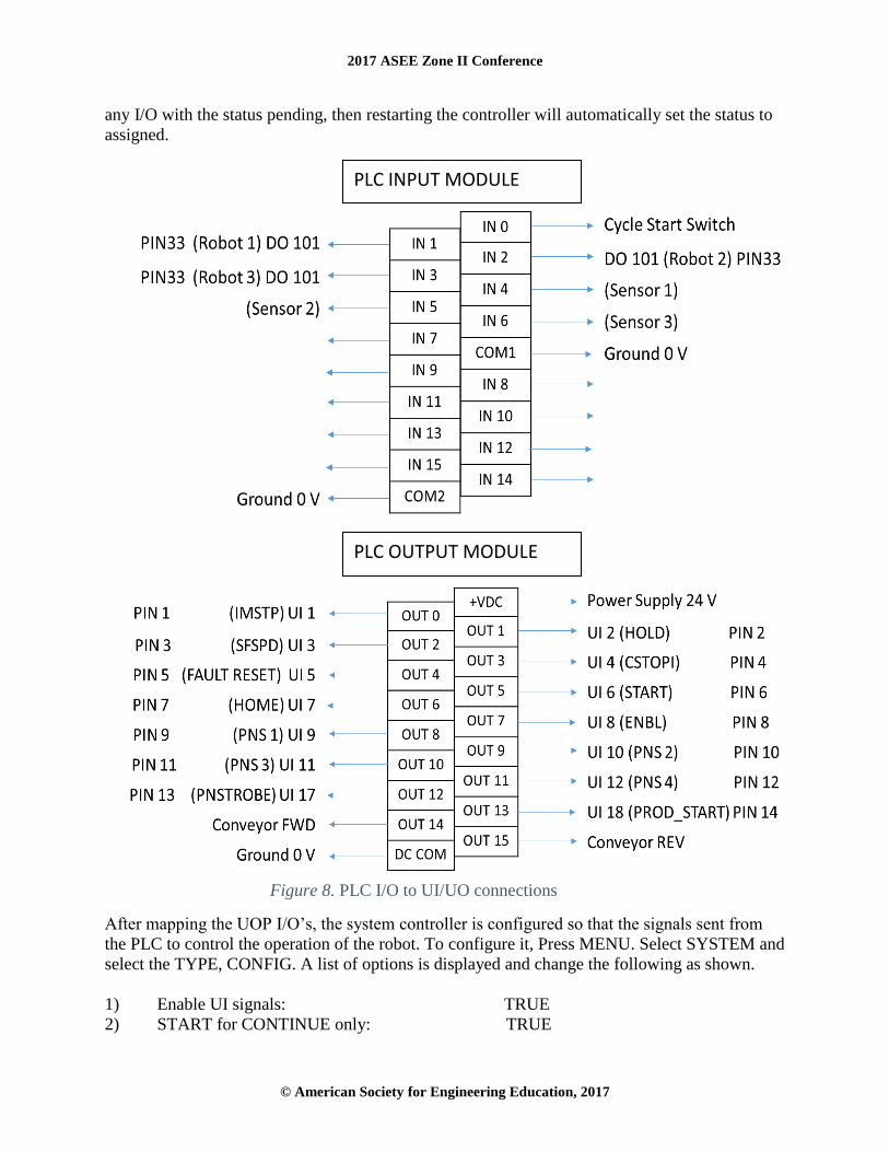
any I/O with the status pending, then restarting the controller will automatically set the status to
assigned.
After mapping the UOP I/O’s, the system controller is configured so that the signals sent from
the PLC to control the operation of the robot. To configure it, Press MENU. Select SYSTEM and
select the TYPE, CONFIG. A list of options is displayed and change the following as shown.
1) Enable UI signals: TRUE
2) START for CONTINUE only: TRUE
PLC INPUT MODULE
PLC OUTPUT MODULE
Figure 8. PLC I/O to UI/UO connections

2017 ASEE Zone II Conference
© American Society for Engineering Education, 2017
3) CSTOPI for ABORT: TRUE
4) Abort all programs by CSTOPI: TRUE
5) PROD_START depend on PNSTROBE: TRUE
6) Detect FAULT_RESET signal: FALL
7) Remote/Local Setup: Remote
# RANGE RACK SLOT START STATUS
1 UI [1— 1 ] 48 1 1 ASSIGNED
2 UI [2— 2 ] 48 1 2 ASSIGNED
3 UI [3— 3 ] 48 1 3 ASSIGNED
4 UI [4— 4 ] 48 1 4 ASSIGNED
5 UI [5— 5 ] 48 1 5 ASSIGNED
6 UI [6— 6 ] 48 1 6 ASSIGNED
7 UI [7— 7 ] 48 1 7 ASSIGNED
8 UI [8— 8 ] 48 1 8 ASSIGNED
9 UI [9— 12 ] 48 1 9 ASSIGNED
10 UI [17— 17 ] 48 1 13 ASSIGNED
11 UI [18— 18 ] 48 1 14 ASSIGNED
12 UI [13— 16 ] 0 0 0 UNASSIGNED
Table 3. Details of the UI's assigned
The PLC ladder logic program initializes the basic signals that are required to run the robot
program. Firstly, Immediate stop, Hold and Safety speed signals are turned on and activated for
production. The fault is reset and the robot is enabled. The program on the robot is saved with
the name PNSxxxx and the signals from sent from PLC are read as binary inputs by the robot
controller. For example, to execute program PNS0011 the signals sent by PLC are PNS1 (20),
PNS2 (21) and PNS4 (23). After the program number is read by the controller. The Program
number select strobe signal (PNSTROBE) selects the program on the robot. Production start
signal executes the program in production mode.
Application Scenarios of Lab Exercises.
Using the above setup to run the robots using PLC, a number of applications can be developed to
perform tasks such as packaging, manufacturing and assembly of parts. Using the above system,
students can create their own and innovative projects for the Robotics Vision course. To provide
hands on experience to the students and explain the working of the integrated system, different
lab exercises have been implemented as a part of the course and are discussed next.
Jenga Blocks Production and Palletizing

2017 ASEE Zone II Conference
© American Society for Engineering Education, 2017
This exercise lets students relate to the various palletizing applications that are used throughout
the industry. There are a few wooden blocks placed on the conveyor in a random orientation as
shown in Figure 10.
The robot’s vision system has to detect the blocks moving on the conveyor, stop the conveyor
and, using the vacuum cup end-of-arm-tooling, pick up the blocks and form the final pallet. This
is done using the palletizing option provided on the FANUC controller where number of rows,
columns and layers of the pallet are defined along with the robot’s approach and retreat points
from the pallet. The second task is to teach the image of the block to the iR-Vision system’s
camera which is mounted exactly above the conveyor. The camera’s search window is defined
on the conveyor closer to the robot for easy approach. After the vision process is defined by the
students, a program is written to integrate the vision with the palletizing program.
Having completed this exercise, students learn to create shorter programs on the teach pendant
for palletizing applications. They also learn the procedure of the iR-Vision system that involves
camera calibration, teaching geometric pattern to the camera and programming the vision
instructions.
Marker pen color sorting and assembly
The main objective of this exercise, demonstrated in Figure 11, is to train the students the ability
of the robotic vision system to differentiate between color and understand the importance of
lighting conditions for the vision system. It also gives an insight to the students about the
working of multiple robots controlled safely with the PLC. Three teams work on three different
robots to program individual tasks.
The color of the markers, blue, red and pink are chosen in the increasing order of contrast. The
belt being black in color makes it difficult for the robot to detect the dark colors such as blue.
The students have to adjust the environment lighting and create enough brightness for the camera
to detect the blue contrast. The caps are placed in the search region of robot 3 and the open
Figure 9. 1) Randomly placed Jenga blocks travelling on conveyor 2) Final Pallet formed
by the robot
2017 ASEE Zone II Conference
© American Society for Engineering Education, 2017
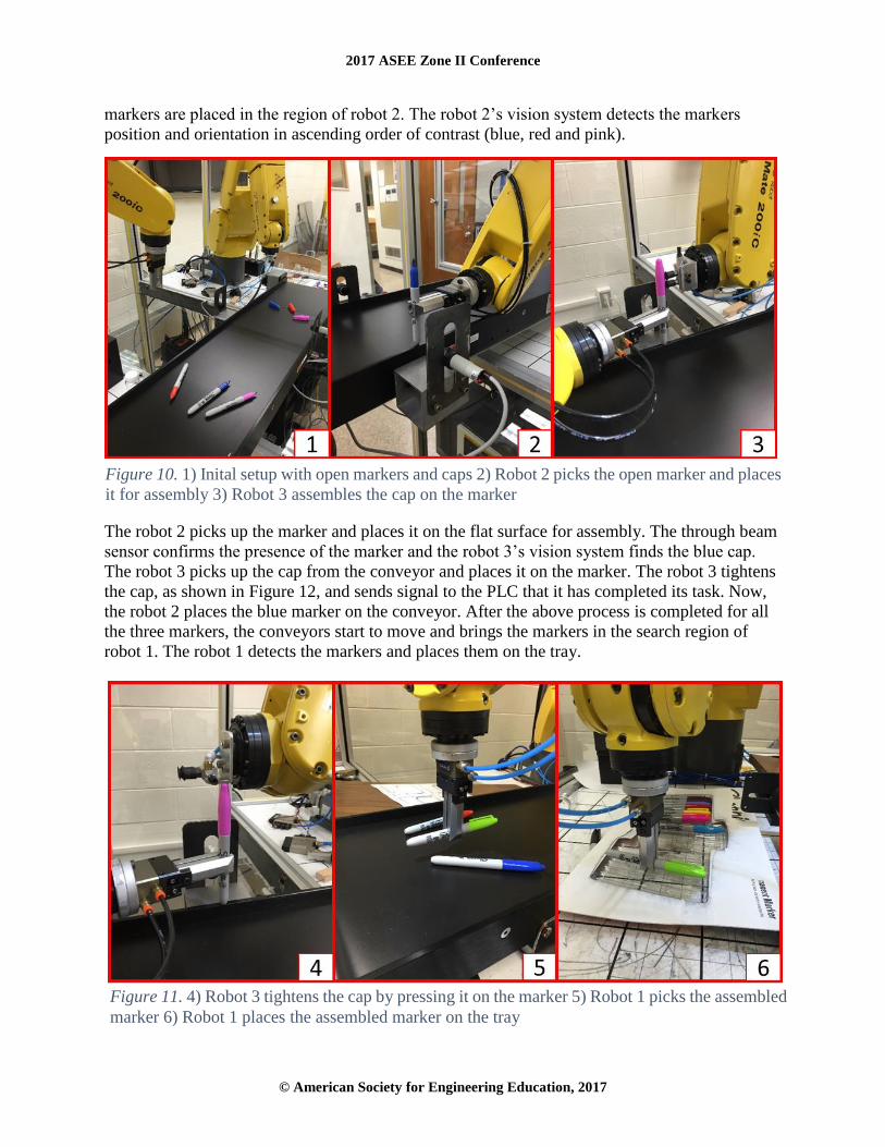
markers are placed in the region of robot 2. The robot 2’s vision system detects the markers
position and orientation in ascending order of contrast (blue, red and pink).
The robot 2 picks up the marker and places it on the flat surface for assembly. The through beam
sensor confirms the presence of the marker and the robot 3’s vision system finds the blue cap.
The robot 3 picks up the cap from the conveyor and places it on the marker. The robot 3 tightens
the cap, as shown in Figure 12, and sends signal to the PLC that it has completed its task. Now,
the robot 2 places the blue marker on the conveyor. After the above process is completed for all
the three markers, the conveyors start to move and brings the markers in the search region of
robot 1. The robot 1 detects the markers and places them on the tray.
Figure 10. 1) Inital setup with open markers and caps 2) Robot 2 picks the open marker and places
it for assembly 3) Robot 3 assembles the cap on the marker
Figure 11. 4) Robot 3 tightens the cap by pressing it on the marker 5) Robot 1 picks the assembled
marker 6) Robot 1 places the assembled marker on the tray

2017 ASEE Zone II Conference
© American Society for Engineering Education, 2017
Combining three of these robotic carts into a single robotic work cell was developed with an aim
to enhance the laboratory usage of these robots along with providing hands-on experience to
students. The course will aim to have many such lab exercises in future.
Conclusion and Future Work
The modifications and development done to the existing education carts provided by FANUC
will provide a greater learning experience for the Robotics Vision course that is being introduced
in the spring semester of 2017. The main objective of creating the robotic workcell is to give
students a maximum exposure to the industrial scenarios that would assist them in their future.
Automation system integrators often design the manufacturing or assembly lines with multiple
robots and other hardware systems. The workcell’s design has been inspired from observing the
current automation lines in different industries such as food and packaging, medical, logistics
and assembly lines. The workcell is an integrated system of three robotic arms, a bi-directional
conveyor, sensors and vision systems. A PLC acts as the master controller and sends signals to
the robot controllers to run the complete system in production. Ladder logic programs have been
created for teaching laboratory exercises that involve different applications such as palletizing
using vision, assembly of parts, color based sorting of pills and identification of parts for
acceptance or rejection.
The workcell design has also opened the doors for students to come up with innovative ideas for
their projects which is a part of the course requirement. Students will now be able to achieve
control over operation of multiple robots and demonstrate their abilities in building a complete
integrated system. Having learnt the process of integrating an automation system, students will
be able to troubleshoot and work on different applications in the industry.
In the future, the workcell can be equipped with capabilities to execute advanced vision based
applications like 3D Bin picking and visual tracking. 3D bin picking is being widely used in the
industry to pick up parts from a bin and place it in the required orientation. Also, by procuring
the visual tracking option for the FANUC controller 9, picking up objects while the conveyor is
running would be one of the various possible applications. The industry demands highly efficient
production cycle times of the automation systems and future laboratory exercises would be
modified to teach the optimum path of operation for robots and vision. Also, since lighting is the
most important aspect of vision, lab exercises involving the usage of different colored lights for
different objects would be implemented.
References
1 International Federation of Robotics, http://ifr.org/
2 Stienecker, Adam, (2008). Applied Industrial Robotics: A Paradigm Shift. American Society for
Engineering Education Annual Conference & Exposition
Retrieved from https://peer.asee.org/applied-industrial-robotics-a-paradigm-shift
3 KUKA Robotics, http://www.kukaconnect.com/robotic-stem-education/
4 FANUC America
http://robot.fanucamerica.com/robotapplications/FANUC_Certified_Education_Robot_Training.aspx
5 ABB, http://www.abb.com/cawp/seitp202/f30f8e1876d77d42c12578cd002034b4.aspx\
6 Sirinterlikci, Arif, Macek, Alexander M, Barnes Jr, Bruce Allen (2015). Development of a Vision-
based Sorting Operation Laboratory: A Student-Driven Project. ASEE Conference, Seattle, WA.

2017 ASEE Zone II Conference
© American Society for Engineering Education, 2017
Retrieved from https://peer.asee.org/development-of-a-vision-based-sorting-operation-laboratory-a-
student-driven-project
7 Ferry, William, Otieno, Andrew (2004). Development Of A Low Cost Laboratory System For
Teaching Automation System Integration In The Manufacturing Engineering Technology Curriculum.
Annual ASEE Conference, Retrieved from https://peer.asee.org/development-of-a-low-cost-laboratory-
system-for-teaching-automation-system-integration-in-the-manufacturing-engineering-technology-
curriculum
8 Mini-Mover Conveyors, http://www.mini-mover.com/
9 FANUC Robotics System R-30iA Controller HandlingTool Setup and Operations Manual
Siddhart Parmar
Mr. Parmar is currently pursuing a graduate degree in Mechanical Engineering at Michigan
Tech. His professional interests include mechanical design, robotics and automation. He can be
reached at [email protected]
Aleksandr Sergeyev
Dr. Sergeyev is Associate Professor in the Electrical Engineering Technology program at
Michigan Tech. He is a FANUC certified instructor in Robotics and oversees all activities of the
FANUC authorized certified training center at Michigan Tech. He has developed and taught
courses in the areas of Robotics and Automation, Power, Electrical Machinery, Programmable
Logical Controllers, Digital Signal Processing, and Optics. He has a strong record publishing in
prestigious journals and conference proceedings such as Measurements Science and Technology,
Adaptive Optics, Sensors and Materials, The Technology Interface International Journal, ASEE,
IEEE, and SPIE. Dr. Sergeyev may be reached at [email protected]
Nasser Alaraje
Dr. Alaraje is an Associate Professor and Program Chair of Electrical Engineering Technology at
Michigan Tech. In 2009, Alaraje was awarded the Golden Jubilee by the College of Engineering
at Assiut University, in Egypt. He has served as an ABET/IEEE-TAC evaluator for electrical
engineering technology and computer engineering technology programs. Dr. Alaraje is a 2013-
14 Fulbright scholarship recipient at Qatar University, where he taught courses on Embedded
Systems. Dr. Alaraje may be reached at [email protected]