Embed Size (px)
Citation preview
AC 2009-124: TEACHING ADVANCED DIGITAL SIGNAL PROCESSING WITHMULTIMEDIA APPLICATIONS IN ENGINEERING TECHNOLOGY PROGRAMS
Li Tan, Purdue University, North CentralLI TAN is currently with the College of Engineering and Technology at Purdue University NorthCentral in Westville, Indiana. He received his M.S. and Ph.D. degrees in Electrical Engineeringfrom the University of New Mexico in 1989 and 1992, respectively. Before he joined PurdueUniversity in 2008 as a faculty member, Dr. Tan had extensively taught analog and digital signalprocessing, and analog and digital communications for over 10 years as a professor at DeVryUniversity in Atlanta, Georgia. Dr. Tan has also worked in the DSP and communication industryfor many years. Dr. Tan is a senior member of the Institute of Electronic and Electronic Engineers(IEEE). His principal technical areas include digital signal processing, adaptive signal processing,and digital communications. He has published a number of papers in these areas. He has authoredand co-authored two textbooks: Digital Signal Processing: Fundamentals and Applications,Elsevier/Academic Press, 2007; and Fundamentals of Analog and Digital Signal Processing,Second Edition, AuthorHouse, 2008.
Jean Jiang, DeVry University, Decatur, GAJEAN JIANG is currently with the College of Engineering and Technology at Purdue UniversityNorth Central in Westville, Indiana. She received her Ph.D. degree in Electrical Engineering fromthe University of New Mexico in 1992. Before she joined Purdue University in 2009 as a facultymember, Dr. Jiang had taught analog signal processing, digital signal processing, and controlsystems for a number of years as a professor at DeVry University in Atlanta, Georgia. Dr. Jiang isa member of the Institute of Electronic and Electronic Engineers (IEEE). Her principal technicalareas are in digital signal processing, adaptive signal processing, and control systems. She haspublished a number of papers in these areas. She has co-authored a textbook: Fundamentals ofAnalog and Digital Signal Processing, Second Edition, AuthorHouse, 2008.
© American Society for Engineering Education, 2009
Page 14.1123.1
Teaching Advanced Digital Signal Processing with Multimedia
Applications in Engineering Technology Programs
Li Tan
College of Engineering and Technology
Purdue University North Central
Jean Jiang
College of Engineering and Technology
Purdue University North Central
Abstract
In this paper, we present our pedagogies and experiences from teaching advanced digital signal
processing (DSP) within the engineering technology curricula, which include electrical,
biomedical, and computer engineering technologies. The course is an elective for senior students
and is designated as the second DSP course in engineering technology programs with a focus on
real-time processing and multimedia applications. The course prerequisite assumes that the
students have acquired working skills of the Laplace transform, the Fourier analysis, the z-
transform, the discrete Fourier transform, and analog and digital filters from the first DSP course.
In this course, the technology students will continue to explore advanced techniques such as real-
time digital filter implementations, adaptive filtering, multi-rate signal processing, and digital
image processing, and will further examine DSP applications in the areas of telecommunications,
biomedical engineering, and multimedia systems. By offering a broad coverage of topics and
case studies, the course could possibly be beneficial to all electrical, biomedical, and computer
engineering technology students.
Since teaching advanced DSP topics throughout the engineering technology program has the
requirement of being at a hands-on and engineering technology level, adopting traditional
teaching approaches and using textbooks dealing with complicated mathematics and theories
used in a four-year engineering program may not be appropriate. In this paper, we will explain
course prerequisites and will describe our teaching methods, which include real-time signal
processing laboratories using low-cost DSP processors, and hands-on projects. We will also
present a course assessment and outcome, which will include how the students apply their gained
DSP knowledge to their capstone senior projects. Finally, we will address the possible
improvement of the course content and associated laboratories.
I. Introduction
Digital signal processing (DSP) technology and its advancements have continuously impacted
the disciplines of electrical, computer, and biomedical engineering technology programs. This is
due to the fact that DSP technology plays a key role in many current applications of electronics,
which include digital telephones, cellular phones, digital satellites, digital TV’s, ECG analyzers,
digital X-rays, and medical image systems in the areas of communications, instrumentation, and
biomedical signal processing. There are many DSP related products such as digital voice
recorders, CD/DVD players, MP3 players, digital cameras, internet audios, and images and
Page 14.1123.2
videos. A quick review of the current jobs advertised in technical magazines and on the internet
web sites further reveals a demand for individuals with a refined DSP knowledge. Hence, the
qualified engineering technologists capable of operating, maintaining, repairing, evaluating, and
helping to specify and design DSP-based products have significant competency for their
employment.
To prepare engineering technology students for such an industrial trend, many undergraduate
programs in engineering technology not only offer a course to cover the fundamentals of DSP,
but also provide a second elective DSP course in which real-time applications and corresponding
advanced topics such as multi-rate signal processing, adaptive filtering, and digital image and
video processing 1, 9, 10
are introduced.
In our engineering technology program, the second DSP elective course is designed for senior
students with a focus on real-time signal processing and multimedia applications. The course
prerequisite assumes that the students have already acquired working skills of the Laplace
transform, the Fourier analysis, the z-transform, the discrete Fourier transform, and analog and
digital filters from the first DSP course. The technology students in this course will continue to
explore advanced techniques such as real-time digital filter implementations, adaptive filtering,
multi-rate signal processing, and digital image processing, and will further examine DSP
applications in the areas of telecommunications, biomedical signal processing, and multimedia
systems. While offering a broad coverage of topics and case studies, this course could be
beneficial to all technology students.
Since teaching advanced DSP topics within the engineering technology program has the
requirement of being at a hands-on and engineering technology level, adopting the traditional
teaching approaches and using textbooks dealing with complicated mathematics and theories
used in the four-year engineering program may not be appropriate. Hence, in this paper, we will
present our pedagogies and experiences from teaching the subjects of advanced DSP in the
engineering technology curricula.
The paper is organized as follows. We will explain the course prerequisites and will describe our
designed course content first, and then we will introduce real-time signal processing laboratories
using low-cost DSP processors such as the TI TMS320C671x DSP board and simulation tools
such as MATLAB, and hands-on projects. We will also present the course assessment and
outcome, which include how the students apply their gained DSP knowledge to their capstone
senior projects. Finally, we will address possible improvement of the course content and
associated laboratories.
II. Course Prerequisite Requirements
In this section, we will explain the course pre-requisites, which can be divided into three
categories, as described below.
A. Signal Processing Course Requirement
The first DSP course covering the key topics of the sampling theorem, digital spectrum, z-
transform, properties of the digital filters, and design of the finite impulse response (FIR) and
Page 14.1123.3
infinite impulse response (IIR) filters is a prerequisite. Students in the advanced DSP course
apply these established skills for designing, implementing, and verifying various applications
such as the digital crossover audio systems, dual tone multi-frequency (DTMF) tone generation
and detection, and so on. Specifically, the skills of the digital FIR filter design and signal
spectral analysis obtained from the first DSP course are necessary for the decimator and
interpolator filter design and verifications in the area of sampling rate conversions. Furthermore,
a grasp of concepts and principles of the first DSP course indicates the gained knowledge of the
analog signal processing (ASP) course, in which three major topics, the Laplace transform,
Fourier analysis, and analog filters, are covered. For example, the Laplace transform and Laplace
transfer function serve for the analog filter design and digital IIR filter design, while the Fourier
analysis supports for spectral analysis and digital FIR filter design with the window functions.
Hence, the prerequisite of the first DSP course implies the ASP course. On the other hand, some
technology program may possibly offer a combined ASP and DSP course, which could be an
alternative for the pre-requisite.
B. Math Requirement
While satisfying the prerequisite of the signal processing course, students are gaining maturity in
the comprehension and application of math including basic calculus, and proficiency in using
algebra. A firm grasp of calculus concepts is beneficial in understanding the advanced course
materials such as the employment of the derivative operation in order to develop the least mean
square (LMS) algorithm for adaptive filters. Since the calculus course is a prerequisite for the
first DSP course or the combined ASP and DSP course, it is not necessary that we list it as an
additional prerequisite.
C. Software Requirement
To design, analyze, and simulate the DSP algorithms, MATLAB programming is required; this
requirement was enforced in the previous signal processing course. On the other hand, to gain
real-time signal processing experience using a DSP board, students are required to code DSP
algorithms using the C language. Similarly, since the students at the senior level have already
acquired their C program knowledge early on in the C programming course, which has been used
in the microcontroller embedded systems course, this requirement can easily be satisfied.
As a summary, the advanced DSP course needs the prerequisites as listed below:
1. Digital signal processing (or analog and digital signal processing)
2. MATLAB programming and basic C programming skills
III. Course Content and Associated Laboratories
We have divided the course content into three portions. First, the DSP fundamentals were
reviewed with an emphasis on real-time digital filter implementation and applications. The
second portion introduced advanced DSP topics, which include adaptive filtering, waveform
coding, and multi-rate signal processing, such as sampling rate conversions. Finally, in the third
portion, we taught students the basic techniques of digital image processing.
Page 14.1123.4
The course was taught for 15 weeks with 3 lecture hours and 3 laboratory hours per week. The
textbook selected was “Digital Signal Processing: Fundamentals and Applications.” published by
Elsevier, 2007 1. The book provides most of the topics required by the course, specifically, the
topics of adaptive filters, multi-rate signal processing, multimedia applications such as waveform
coding, image processing basics, and video signals. The text presents course materials at an
appropriate math level, uses an ample amount of simplified and clearly worked examples, adopts
MATLAB programs to demonstrate simulations, and provides application examples to motivate
students. Simplification of real-time DSP implementations to the engineering technology level is
a plus. The book also covers materials taught in the first DSP course (Chapter 1 through Chapter
8 1) and can serve as a comprehensive reference.
To minimize the time for learning different simulation tools, we simply selected MATLAB,
which was familiarized by students when they took the first DSP course, as a major simulation
and design tool. However, other simulation tools were also welcomed when time was permitted.
The TI TMS320C671X DSP board was chosen as a platform for teaching real-time signal
processing. Students had gained their working knowledge of the TI Code Composer Studio (CCS)
and had experienced real-time DSP coding by building the CCS project, compiling and linking it,
loading the executable code onto the C671X DSP board, and running the DSP programs. We
requested the students to implement DSP algorithms using a float-point format due to its
simplicity (no signal scaling and coefficient quantization are necessary) in order to ensure that
they can focus on various applications.
A. Real-Time Digital Filter Implementations
We first briefly reviewed several key topics from the first DSP course: the sampling theorem,
DFT and signal spectrum, filter frequency responses, and filter implementations using the direct
form I and direct form II. These selected topics were covered in Chapters 2, 4, 6 1. Again, we
also concisely reviewed the digital filter design in Chapters 7 and 8 dealing with the FIR and IIR
filters. As shown in Table 1, Experiment 1 introduces a tutorial on TI CCS with the
TMS320C671X DSP board 3-8
to establish the students’ working knowledge. Experiment 2 is a
comprehensive MATLAB experiment which reviews the signal spectral analysis using the fast
Fourier transform (FFT), and the design of digital FIR and IIR filters.
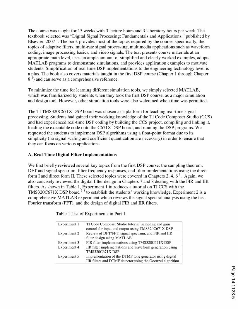
Table 1 List of Experiments in Part 1.
Experiment 1 TI Code Composer Studio tutorial, sampling and gain
control for input and output using TMS320C671X DSP
Experiment 2 Review of DFT/FFT, signal spectrum, and FIR and IIR
filter design using MATLAB
Experiment 3 FIR filter implementations using TMS320C671X DSP
Experiment 4 IIR filter implementations and waveform generation using
TMS320C671X DSP
Experiment 5 Implementation of the DTMF tone generator using digital
IIR filters and DTMF detector using the Goertzel algorithm
Page 14.1123.5
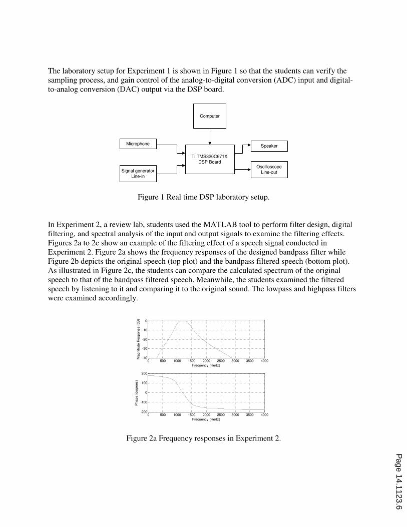
The laboratory setup for Experiment 1 is shown in Figure 1 so that the students can verify the
sampling process, and gain control of the analog-to-digital conversion (ADC) input and digital-
to-analog conversion (DAC) output via the DSP board.
TI TMS320C671X
DSP Board
Computer
Microphone
Signal generatorLine-in
Speaker
OscilloscopeLine-out
Figure 1 Real time DSP laboratory setup.
In Experiment 2, a review lab, students used the MATLAB tool to perform filter design, digital
filtering, and spectral analysis of the input and output signals to examine the filtering effects.
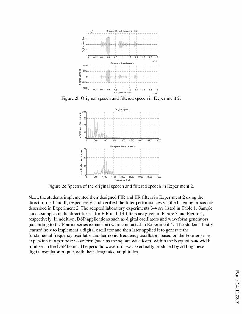
Figures 2a to 2c show an example of the filtering effect of a speech signal conducted in
Experiment 2. Figure 2a shows the frequency responses of the designed bandpass filter while
Figure 2b depicts the original speech (top plot) and the bandpass filtered speech (bottom plot).
As illustrated in Figure 2c, the students can compare the calculated spectrum of the original
speech to that of the bandpass filtered speech. Meanwhile, the students examined the filtered
speech by listening to it and comparing it to the original sound. The lowpass and highpass filters
were examined accordingly.
0 500 1000 1500 2000 2500 3000 3500 4000-200
-100
0
100
200
Frequency (Hertz)
Phase (
degre
es)
0 500 1000 1500 2000 2500 3000 3500 4000-40
-30
-20
-10
0
Frequency (Hertz)
Magnitude R
esponse (
dB
)
Figure 2a Frequency responses in Experiment 2.
Page 14.1123.6
0 0.2 0.4 0.6 0.8 1 1.2 1.4 1.6 1.8 2
x 104
-2
-1
0
1
2x 10
4
Origib
al sam
ple
s
Speech: We lost the golden chain.
0 0.2 0.4 0.6 0.8 1 1.2 1.4 1.6 1.8 2
x 104
-4000
-2000
0
2000
4000
Number of samples
Filt
ere
d S
am
ple
s
Bandpass filtered speech.
Figure 2b Original speech and filtered speech in Experiment 2.
0 500 1000 1500 2000 2500 3000 3500 40000
50
100
150
200
Am
plit
ud
e s
pe
ctr
um
Ak
Original speech
0 500 1000 1500 2000 2500 3000 3500 40000
10
20
30
Am
plit
ud
e s
pe
ctr
um
Ak
Frequency (Hz)
Bandpass filtered speech
Figure 2c Spectra of the original speech and filtered speech in Experiment 2.
Next, the students implemented their designed FIR and IIR filters in Experiment 2 using the
direct forms I and II, respectively, and verified the filter performances via the listening procedure
described in Experiment 2. The adopted laboratory experiments 3-4 are listed in Table 1. Sample
code examples in the direct form I for FIR and IIR filters are given in Figure 3 and Figure 4,
respectively. In addition, DSP applications such as digital oscillators and waveform generators
(according to the Fourier series expansion) were conducted in Experiment 4. The students firstly
learned how to implement a digital oscillator and then later applied it to generate the
fundamental frequency oscillator and harmonic frequency oscillators based on the Fourier series
expansion of a periodic waveform (such as the square waveform) within the Nyquist bandwidth
limit set in the DSP board. The periodic waveform was eventually produced by adding these
digital oscillator outputs with their designated amplitudes.
Page 14.1123.7
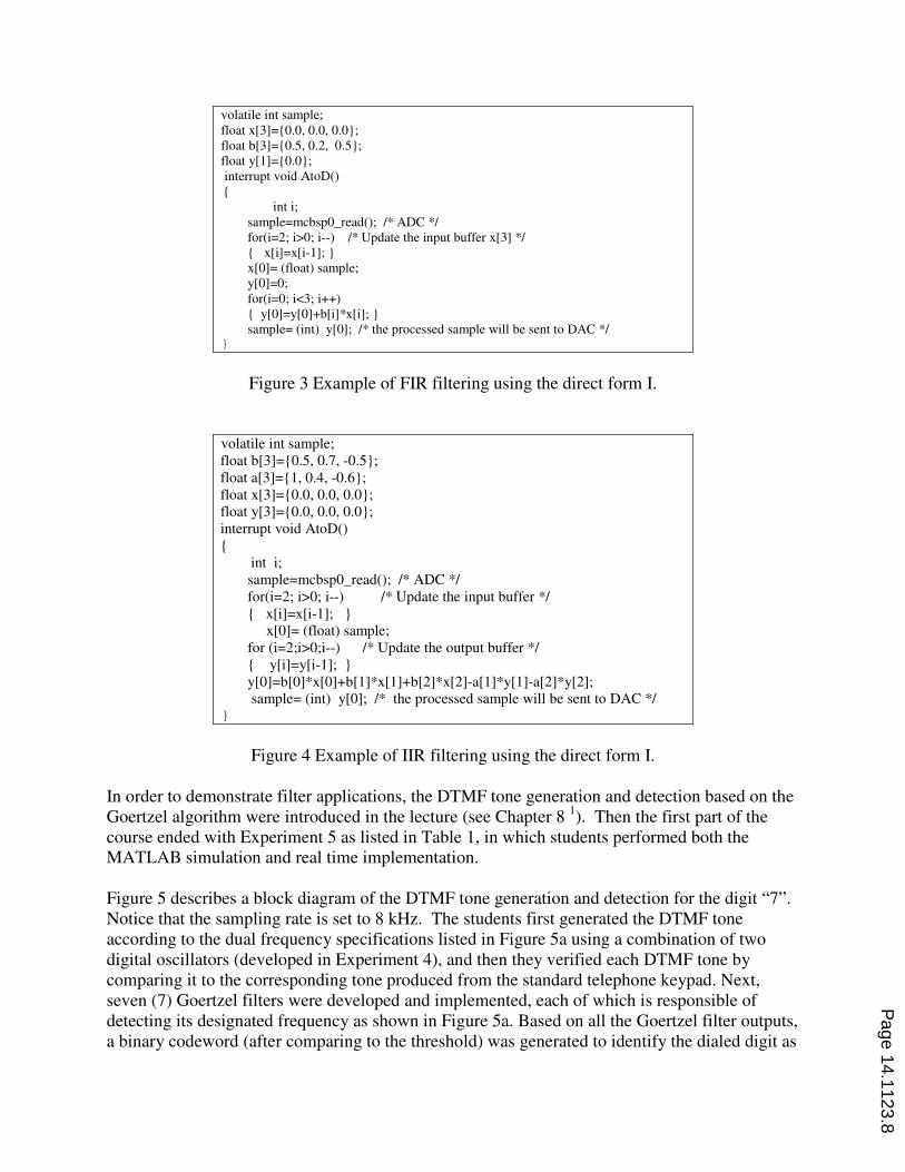
Figure 3 Example of FIR filtering using the direct form I.
Figure 4 Example of IIR filtering using the direct form I.
In order to demonstrate filter applications, the DTMF tone generation and detection based on the
Goertzel algorithm were introduced in the lecture (see Chapter 8 1). Then the first part of the
course ended with Experiment 5 as listed in Table 1, in which students performed both the
MATLAB simulation and real time implementation.
Figure 5 describes a block diagram of the DTMF tone generation and detection for the digit “7”.
Notice that the sampling rate is set to 8 kHz. The students first generated the DTMF tone
according to the dual frequency specifications listed in Figure 5a using a combination of two
digital oscillators (developed in Experiment 4), and then they verified each DTMF tone by
comparing it to the corresponding tone produced from the standard telephone keypad. Next,
seven (7) Goertzel filters were developed and implemented, each of which is responsible of
detecting its designated frequency as shown in Figure 5a. Based on all the Goertzel filter outputs,
a binary codeword (after comparing to the threshold) was generated to identify the dialed digit as
volatile int sample;
float x[3]={0.0, 0.0, 0.0};
float b[3]={0.5, 0.2, 0.5};
float y[1]={0.0};
interrupt void AtoD()
{
int i;
sample=mcbsp0_read(); /* ADC */
for(i=2; i>0; i--) /* Update the input buffer x[3] */
{ x[i]=x[i-1]; }
x[0]= (float) sample;
y[0]=0;
for(i=0; i<3; i++)
{ y[0]=y[0]+b[i]*x[i]; }
sample= (int) y[0]; /* the processed sample will be sent to DAC */ }
volatile int sample;
float b[3]={0.5, 0.7, -0.5};
float a[3]={1, 0.4, -0.6};
float x[3]={0.0, 0.0, 0.0};
float y[3]={0.0, 0.0, 0.0};
interrupt void AtoD()
{
int i;
sample=mcbsp0_read(); /* ADC */
for(i=2; i>0; i--) /* Update the input buffer */
{ x[i]=x[i-1]; }
x[0]= (float) sample;
for (i=2;i>0;i--) /* Update the output buffer */
{ y[i]=y[i-1]; }
y[0]=b[0]*x[0]+b[1]*x[1]+b[2]*x[2]-a[1]*y[1]-a[2]*y[2];
sample= (int) y[0]; /* the processed sample will be sent to DAC */ }
Page 14.1123.8
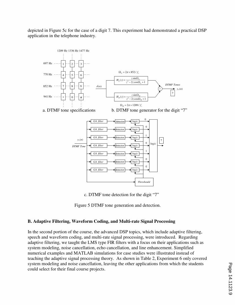
depicted in Figure 5c for the case of a digit 7. This experiment had demonstrated a practical DSP
application in the telephone industry.
1 2 3
4 5 6
7 8 9
* 0 #
1209 Hz 1336 Hz 1477 Hz
697 Hz
770 Hz
852 Hz
941 Hz
H zz
z zL
L
L
( )sin
cos?
/ −
Ψ
Ψ2 2 1
H zz
z zH
H
H
( )sin
cos?
/ −
Ψ
Ψ2 2 1
φ ( )n−
DTMF Tones
7
ΨL sf? ∂2 852ρ /
ΨH sf? ∂2 1209ρ /
y n7 ( )
a. DTMF tone specifications b. DTMF tone generator for the digit “7”
GA filter
GA filter
GA filter
GA filter
GA filter
GA filter
GA filter
y n7 ( )
DTMF Tone
detector
Threshould
log ic
log ic
log ic
log ic
log ic
log ic
log ic
logic
7
1
0
0
0
1
0
0
detector
detector
detector
detector
detector
detector
c. DTMF tone detection for the digit “7”
Figure 5 DTMF tone generation and detection.
B. Adaptive Filtering, Waveform Coding, and Multi-rate Signal Processing
In the second portion of the course, the advanced DSP topics, which include adaptive filtering,
speech and waveform coding, and multi-rate signal processing, were introduced. Regarding
adaptive filtering, we taught the LMS type FIR filters with a focus on their applications such as
system modeling, noise cancellation, echo cancellation, and line enhancement. Simplified
numerical examples and MATLAB simulations for case studies were illustrated instead of
teaching the adaptive signal processing theory. As shown in Table 2, Experiment 6 only covered
system modeling and noise cancellation, leaving the other applications from which the students
could select for their final course projects.
Page 14.1123.9
Table 2 List of Experiments in Part 2.
Experiment 6 Adaptive filtering: system modeling and noise cancellation
Experiment 7 PCM, mu-law PCM, and ADPCM coding with applications
to speech compression
Experiment 8 Sampling rate conversions and polyphase implementations
for decimation and interpolation filters
Real-time implementation of noise cancellation requires two ADC units (one for sensing the
primary signal and the other for sensing the reference signal) and one DAC unit for outputting
the enhanced signal. This is challenging in our real-time implementation, since the
TMS320C671X DSP board only accommodates one ADC unit and one DAC unit. However, we
could adopt a modified laboratory setup for noise cancellation as depicted in Figure 6, where the
primary signal is a generated sinusoid corrupted internally by a disturbance, which is produced
from the simulated channel using the sensed reference noise obtained from the ADC channel on
the DSP board. The adaptive LMS FIR filter uses the sensed reference noise, internal error
signal, and the LMS algorithm to produce the canceling output. This canceling output is
subtracted from the corrupted signal to remove the correlated noise. The resultant enhanced
signal is then sent to the DAC channel, which produces a clean signal when the adaptive filter
converges and continues to operate.
−
y n( )
)()()( nnnsnd −?
x n( )
e n d n y n s n( ) ( ) ( ) ~( )? / ?
−ADC
ADC
DAC
Adaptive filter
LMS algorithm
Noise
Signal and noise Error signalCorrupted signal
Cancelling outputInput
Enhance signal-
a. Principle of noise cancellation
−
−
/
Noise
Sinewave generator
Adaptive
FIR filter
x n n( ) ( )? φ
( )y n ADF output?
e n( ) Output
−( )d n corrupted signal?
( )Channel simulated
( ) sinusoidyy n ?
( )n n noise?DAC
ADC
( )xn n
b. Laboratory setup for noise cancellation
Figure 6 Laboratory setup for noise cancellation using the adaptive LMS filter.
Page 14.1123.10
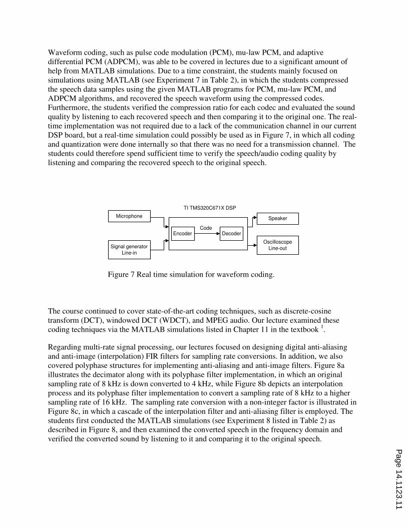
Waveform coding, such as pulse code modulation (PCM), mu-law PCM, and adaptive
differential PCM (ADPCM), was able to be covered in lectures due to a significant amount of
help from MATLAB simulations. Due to a time constraint, the students mainly focused on
simulations using MATLAB (see Experiment 7 in Table 2), in which the students compressed
the speech data samples using the given MATLAB programs for PCM, mu-law PCM, and
ADPCM algorithms, and recovered the speech waveform using the compressed codes.
Furthermore, the students verified the compression ratio for each codec and evaluated the sound
quality by listening to each recovered speech and then comparing it to the original one. The real-
time implementation was not required due to a lack of the communication channel in our current
DSP board, but a real-time simulation could possibly be used as in Figure 7, in which all coding
and quantization were done internally so that there was no need for a transmission channel. The
students could therefore spend sufficient time to verify the speech/audio coding quality by
listening and comparing the recovered speech to the original speech.
Microphone
Signal generator
Line-in
Speaker
Oscilloscope
Line-out
Encoder DecoderCode
TI TMS320C671X DSP
Figure 7 Real time simulation for waveform coding.
The course continued to cover state-of-the-art coding techniques, such as discrete-cosine
transform (DCT), windowed DCT (WDCT), and MPEG audio. Our lecture examined these
coding techniques via the MATLAB simulations listed in Chapter 11 in the textbook 1.
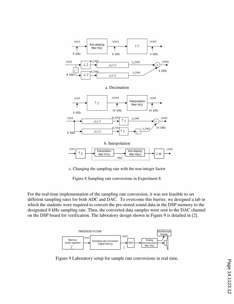
Regarding multi-rate signal processing, our lectures focused on designing digital anti-aliasing
and anti-image (interpolation) FIR filters for sampling rate conversions. In addition, we also
covered polyphase structures for implementing anti-aliasing and anti-image filters. Figure 8a
illustrates the decimator along with its polyphase filter implementation, in which an original
sampling rate of 8 kHz is down converted to 4 kHz, while Figure 8b depicts an interpolation
process and its polyphase filter implementation to convert a sampling rate of 8 kHz to a higher
sampling rate of 16 kHz. The sampling rate conversion with a non-integer factor is illustrated in
Figure 8c, in which a cascade of the interpolation filter and anti-aliasing filter is employed. The
students first conducted the MATLAB simulations (see Experiment 8 listed in Table 2) as
described in Figure 8, and then examined the converted speech in the frequency domain and
verified the converted sound by listening to it and comparing it to the original speech.
Page 14.1123.11
Anti-aliasing
filter H(z)
x n( ) w n( )
2±
y m( )
8 kHz 8 kHz 4 kHz
−0 ( )zτ
1( )zτ
x n( ) y m0 ( )
y m1( )z/1
y m( )
8 kHz
4 kHz
w m0 ( )
w m1( )
2±
2±
a. Decimation
Interpolationfilter H(z)
x n( )
2↓
y m( )w m( )
8 kHz16 kHz 16 kHz
−0 ( )zτ
1( )zτ
x n( ) y m0 ( )
y m1( )z/1
y m( )
8 kHz
16 kHz
w n0 ( )
w n1( )
2↓
2↓
b. Interpolation
Interpolation
filter H1(z)
x n( )
L↓Anti-aliasing
filter H2(z)
( )y m
M± H(z)
c. Changing the sampling rate with the non-integer factor
Figure 8 Sampling rate conversions in Experiment 8.
For the real-time implementation of the sampling rate conversion, it was not feasible to set
different sampling rates for both ADC and DAC. To overcome this barrier, we designed a lab in
which the students were required to convert the pre-stored sound data in the DSP memory to the
designated 8 kHz sampling rate. Then, the converted data samples were sent to the DAC channel
on the DSP board for verification. The laboratory design shown in Figure 9 is detailed in [2].
Memory:Audio segment
Sampling rate conversion
Digital fitering
x n( )y m( )
Analog
reconstructionfilter H(s)
DAC
sf
sf
TMS320C671X DSK Oscilloscope
Display
Figure 9 Laboratory setup for sample rate conversions in real time.
Page 14.1123.12
C. Image Processing Basics
The third portion of the course introduced image processing techniques. Topics regarding image
processing are especially beneficial to technology students in biomedical engineering. Instead of
developing algorithms, we focused on teaching image processing concepts and the usage of
software for basic processing techniques such as image histogram equalizations, image
segmentations, image noise filtering, pseudo color generation, and JPEG image compression.
Experiments 9-10, which are listed in Table 3, have an emphasis on using the MATLAB tool
instead of the algorithm design.
Table 3 List of Experiments in Part 3.
Experiment 9 Image conversion and enhancement using MATLAB
Experiment 10 Image edge detection and pseudo color generation
using MATLAB
Experiment 11 Quality effects on JPEG image compression using
MATLAB
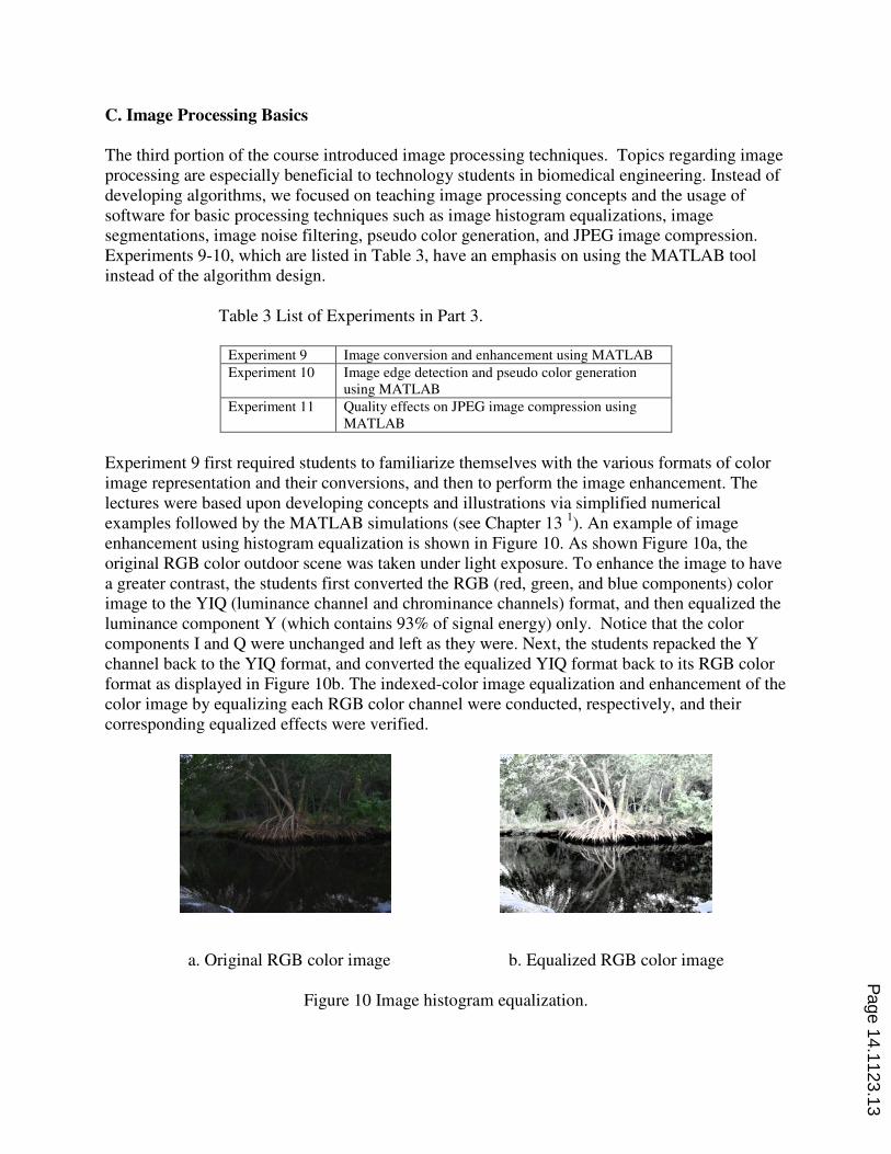
Experiment 9 first required students to familiarize themselves with the various formats of color
image representation and their conversions, and then to perform the image enhancement. The
lectures were based upon developing concepts and illustrations via simplified numerical
examples followed by the MATLAB simulations (see Chapter 13 1). An example of image
enhancement using histogram equalization is shown in Figure 10. As shown Figure 10a, the
original RGB color outdoor scene was taken under light exposure. To enhance the image to have
a greater contrast, the students first converted the RGB (red, green, and blue components) color
image to the YIQ (luminance channel and chrominance channels) format, and then equalized the
luminance component Y (which contains 93% of signal energy) only. Notice that the color
components I and Q were unchanged and left as they were. Next, the students repacked the Y
channel back to the YIQ format, and converted the equalized YIQ format back to its RGB color
format as displayed in Figure 10b. The indexed-color image equalization and enhancement of the
color image by equalizing each RGB color channel were conducted, respectively, and their
corresponding equalized effects were verified.
a. Original RGB color image b. Equalized RGB color image
Figure 10 Image histogram equalization.
Page 14.1123.13
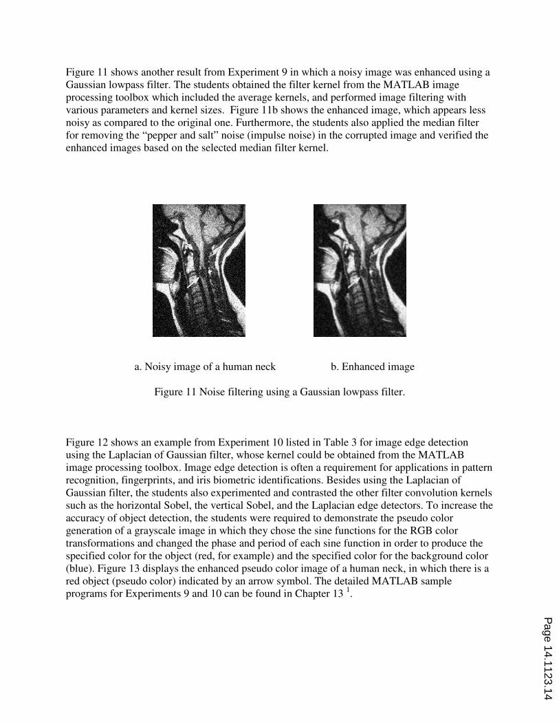
Figure 11 shows another result from Experiment 9 in which a noisy image was enhanced using a
Gaussian lowpass filter. The students obtained the filter kernel from the MATLAB image
processing toolbox which included the average kernels, and performed image filtering with
various parameters and kernel sizes. Figure 11b shows the enhanced image, which appears less
noisy as compared to the original one. Furthermore, the students also applied the median filter
for removing the “pepper and salt” noise (impulse noise) in the corrupted image and verified the
enhanced images based on the selected median filter kernel.
a. Noisy image of a human neck b. Enhanced image
Figure 11 Noise filtering using a Gaussian lowpass filter.
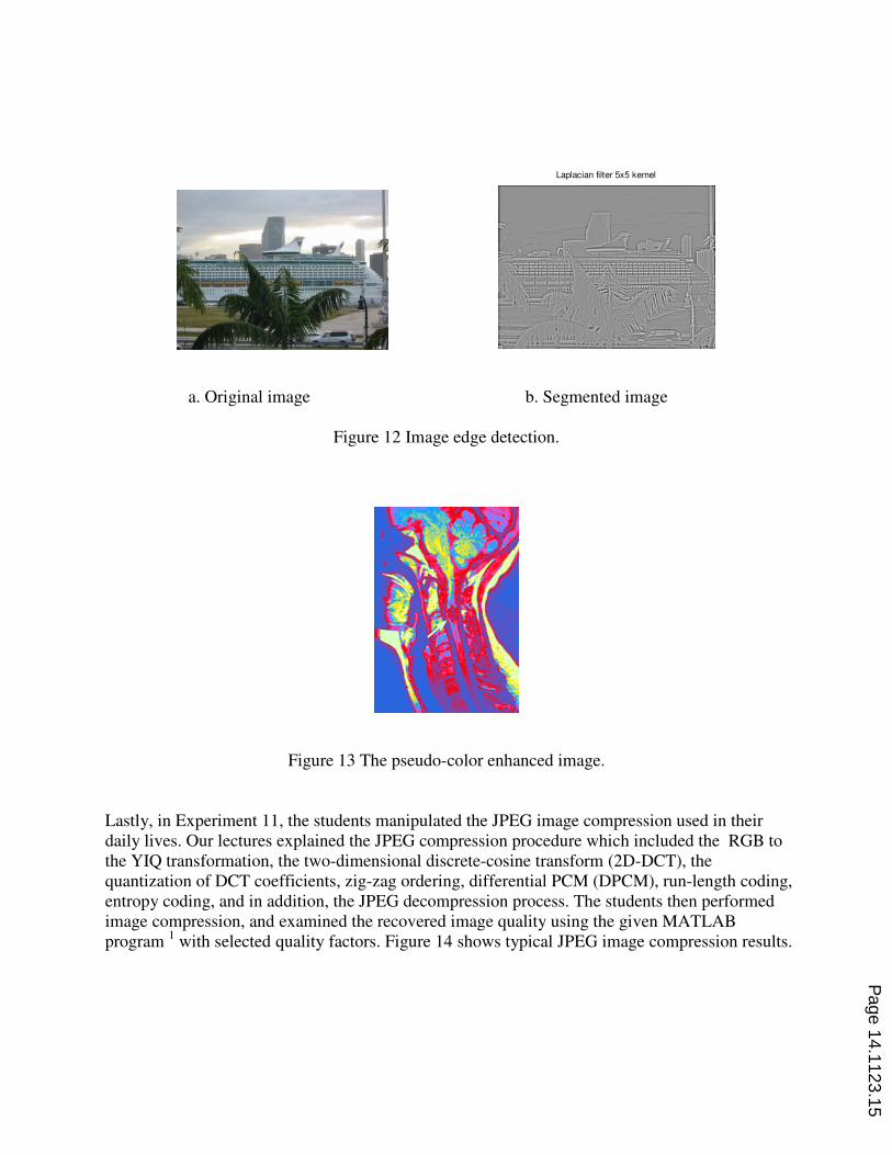
Figure 12 shows an example from Experiment 10 listed in Table 3 for image edge detection
using the Laplacian of Gaussian filter, whose kernel could be obtained from the MATLAB
image processing toolbox. Image edge detection is often a requirement for applications in pattern
recognition, fingerprints, and iris biometric identifications. Besides using the Laplacian of
Gaussian filter, the students also experimented and contrasted the other filter convolution kernels
such as the horizontal Sobel, the vertical Sobel, and the Laplacian edge detectors. To increase the
accuracy of object detection, the students were required to demonstrate the pseudo color
generation of a grayscale image in which they chose the sine functions for the RGB color
transformations and changed the phase and period of each sine function in order to produce the
specified color for the object (red, for example) and the specified color for the background color
(blue). Figure 13 displays the enhanced pseudo color image of a human neck, in which there is a
red object (pseudo color) indicated by an arrow symbol. The detailed MATLAB sample
programs for Experiments 9 and 10 can be found in Chapter 13 1.
Page 14.1123.14
Laplacian filter 5x5 kernel
a. Original image b. Segmented image
Figure 12 Image edge detection.
Figure 13 The pseudo-color enhanced image.
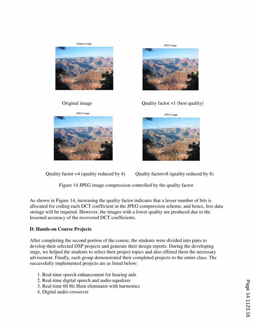
Lastly, in Experiment 11, the students manipulated the JPEG image compression used in their
daily lives. Our lectures explained the JPEG compression procedure which included the RGB to
the YIQ transformation, the two-dimensional discrete-cosine transform (2D-DCT), the
quantization of DCT coefficients, zig-zag ordering, differential PCM (DPCM), run-length coding,
entropy coding, and in addition, the JPEG decompression process. The students then performed
image compression, and examined the recovered image quality using the given MATLAB
program 1 with selected quality factors. Figure 14 shows typical JPEG image compression results.
Page 14.1123.15
Original image
JPEG image
Original image Quality factor =1 (best quality)
JPEG imageJPEG image
Quality factor =4 (quality reduced by 4) Quality factor=8 (quality reduced by 8)
Figure 14 JPEG image compression controlled by the quality factor.
As shown in Figure 14, increasing the quality factor indicates that a lesser number of bits is
allocated for coding each DCT coefficient in the JPEG compression scheme, and hence, less data
storage will be required. However, the images with a lower quality are produced due to the
lessened accuracy of the recovered DCT coefficients.
D. Hands-on Course Projects
After completing the second portion of the course, the students were divided into pairs to
develop their selected DSP projects and generate their design reports. During the developing
stage, we helped the students to select their project topics and also offered them the necessary
advisement. Finally, each group demonstrated their completed projects to the entire class. The
successfully implemented projects are as listed below:
1. Real-time speech enhancement for hearing aids
2. Real-time digital speech and audio equalizer
3. Real-time 60 Hz Hum eliminator with harmonics
4. Digital audio crossover
Page 14.1123.16
5. Real-time line enhancement using adaptive filtering
6. DTMF tone generator and DTMF tone decoder
7. Multi-rate signal processing of audio signal
8. Medical image enhancement
IV. Course Outcome and Assessment
Upon the completion of the course, a survey was conducted to ask each student to evaluate his or
her achievement. Table 4 indicates survey results collected from the previous three semesters
from a total number of 42 students. Note that the rating scale in Table 4 was based on the
percentage of the overall students.
Table 4 Student Survey for achievements.
Rating scale Level of
understanding
Excitements Excitement Textbook
4 - excellent 85% 90% 80% 90%
3 - good 15% 10% 15% 10%
2 - fair 0% 0% 5% 0%
1 -unsatisfactory 0% 0% 0% 0%
Most of the students remained excited about the course, since the hands-on real-time laboratories
had motivated them. Some students felt that the CCS tool required more effort for which to
become familiarized. The textbook also helped a great deal to develop concepts using the worked
numerical examples and MATLAB simulation examples.
After learning advanced DSP, the technology students had applied their newly gained knowledge
and skills to their senior capstone projects. In our campus, senior students are required to present
and demonstrate their senior projects in the senior project fair, in which those projects were
evaluated by the engineering technology faculty members and other senior students. Some DSP
related senior projects are included below. Notice that there are 3 EET (electrical engineering
technology), 2 CET (computer engineering technology), and 3 BMET (biomedical engineering
technology) projects.
1. Voice controlled digital audio equalizer (EET)
2. Voice controlled wireless music player (EET)
3. Smart house with speech recognition system (EET)
4. Robot controlled using DTMF tones (CET)
5. Security system using fingerprint identification (CET)
6. Health monitoring system with Electrocardiagraphy (ECG) and Electroencephalogram
(EEG) (BMET))
7. EEG signal processing and its applications (BMET)
8. Robot arm control using Electromyography (EMG ) signal processing (BMET)
We summarized the results of senior project evaluations in Table 2, in which the rating scale is in
terms of the percentage each of these eight projects received.
Page 14.1123.17
Table 5 Evaluations of DSP related senior projects.
Rating scale Project
performance
4 - excellent 75%
3 - good 25%
2 - fair 0.0%
1 - unsatisfactory 0.0%
As shown in Table 5, 75% of the DSP related projects achieved an “excellent” rating during the
evaluation while the remaining percentage obtained a “good” rating. The evaluation data shows
promising results in which students continue to apply their gained DSP knowledge to their career
development. It is very encouraging to teach the advanced DSP course in the engineering
technology program.
V. Future Improvement
Based on our experiences from teaching advanced DSP, we felt that in Portion 1, all the
lectures containing well-established topics including the digital spectrum, the FIR and IIR filter
implementations and developed laboratories are suitable. Even though the topics of adaptive
filtering, waveform coding and multi-rate signal processing in Portion 2 seemed challenging to
our technology students due to the demand of their math proficiency to understand certain
subjects, however, we have successfully delivered the course materials with an emphasis on
principles and hands-on applications instead of theoretical development. In this regard, and based
on the DSP industrial trend, we could improve the course by introducing additional topics such
as subband coding and wavelet coding (as well as its applications). Portion 3 serves as a good
introduction to digital image processing, in which the students can explore more applications and
develop more enthusiasm in this field. As a result, the students could be ready to take the image,
video, and multimedia processing courses if they are determined to pursue a career in this field.
To improve our lab, we should make use of the lab equipment fund to adopt more advanced DSP
platforms with multi-channel ADCs and DACs, so that many practical real-time DSP laboratory
projects can be developed.
VI. Conclusions
It has been a continuous demand in the industry for the engineering technology students to
possess a working knowledge of the advanced DSP techniques. The traditional treatment of
teaching those subjects using the profound mathematics is not appropriate. However, with the
mathematical simplification equipped with numerical examples, MATLAB simulations, and
well-designed laboratories, the technology students are able to grasp concepts effectively and
apply their gained DSP knowledge to their careers and future technical practice.
Page 14.1123.18
VII. References
1. L. Tan, Digital Signal Processing: Fundamentals and Applications. Elsevier/Academic Press, 2007.
2. L. Tan, J. Jiang, A Simple DSP Laboratory Project for Teaching Real-Time Signal Sampling Rate Conversions,
the Interface Technology Journal, Vol. 9, No. 1, Fall 2008.
3. N. Kehtaranavaz, and B., Simsek, C6x-Based Digital Signal Processing, Prentice Hall, Upper Saddle River,
New Jersey 07458, 2000.
4. Texas Instruments, TMS320C6x CPU and Instruction Set Reference Guide, Literature ID# SPRU 189C, Texas
Instruments, Dallas, Texas, 1998.
5. Texas Instruments, Code Composer Studio: Getting Started Guide, Texas Instruments, Dallas, Texas, 2001.
6. P. M., Embree, C Algorithm for Real-Time DSP, Upper Saddle River, Prentice-Hall, 1995.
7. W. Gan, S. Kuo, S, “Teaching DSP Software Development: From Design to Fixed-Point implementations,”
IEEE Trans. on Education, vol. 49, issue 1, pp. 122-131, February 2006.
8. N. Dahnoun, Digital Signal Implementation Using the TMS320C6000TM DSP Platform, Prentice-Hall, 2000.
9. Ifeachor, Emmanuel and Jervis, Barrie. Digital Signal Processing, A Practical Approach, Prentice-Hall
Publishing, 2002.
10. de Vegte, Joyce Van. Fundamentals of Digital Signal Processing, Prentice-Hall Publishing, 2002.
Biographies
LI TAN is currently with the College of Engineering and Technology at Purdue University North Central in
Westville, Indiana. He received his M.S. and Ph.D. degrees in Electrical Engineering from the University of New
Mexico in 1989 and 1992, respectively. Before he joined Purdue University in 2008 as a faculty member, Dr. Tan
had extensively taught analog and digital signal processing, and analog and digital communications for over 10
years as a professor at DeVry University in Atlanta, Georgia. Dr. Tan has also worked in the DSP and
communication industry for many years.
Dr. Tan is a senior member of the Institute of Electronic and Electronic Engineers (IEEE). His principal technical
areas include digital signal processing, adaptive signal processing, and digital communications. He has published a
number of papers in these areas. He has also authored and co-authored two textbooks: Digital Signal Processing:
Fundamentals and Applications, Elsevier/Academic Press, 2007; and Fundamentals of Analog and Digital Signal
Processing, Second Edition, AuthorHouse, 2008.
JEAN JIANG is currently with the College of Engineering and Technology at Purdue University North Central in
Westville, Indiana. She received her Ph.D. degree in Electrical Engineering from the University of New Mexico in
1992. Before she joined Purdue University in 2009 as a faculty member, Dr. Jiang had taught analog signal
processing, digital signal processing, and control systems for a number of years as a professor at DeVry University
in Atlanta, Georgia.
Dr. Jiang is a member of the Institute of Electronic and Electronic Engineers (IEEE). Her principal technical areas
are in digital signal processing, adaptive signal processing, and control systems. She has published a number of
papers in these areas. She has co-authored a textbook: Fundamentals of Analog and Digital Signal Processing,
Second Edition, AuthorHouse, 2008.
Page 14.1123.19

![ECE-V-DIGITAL SIGNAL PROCESSING [10EC52] …vtusolution.in/.../digital-signal-processing-10ec52.pdfDigital vtusolution.in Signal Processing 10EC52 TEXT BOOK: 1. DIGITAL SIGNAL PROCESSING](https://img.pdfslide.us/doc/110x75/5afe42bb7f8b9a256b8ccd2e/ece-v-digital-signal-processing-10ec52-signal-processing-10ec52-text-book.jpg)


![Wavelets and Signal Processingcm.dmi.unibas.ch/teaching/wavelets/wave.pdf · Wavelets and Signal Processing Reinhold Schneider Sommersemester 2000 Recommended Literature [1] St´ephane](https://img.pdfslide.us/doc/110x75/5f492dcace675317383c2363/wavelets-and-signal-wavelets-and-signal-processing-reinhold-schneider-sommersemester.jpg)