Embed Size (px)
Citation preview

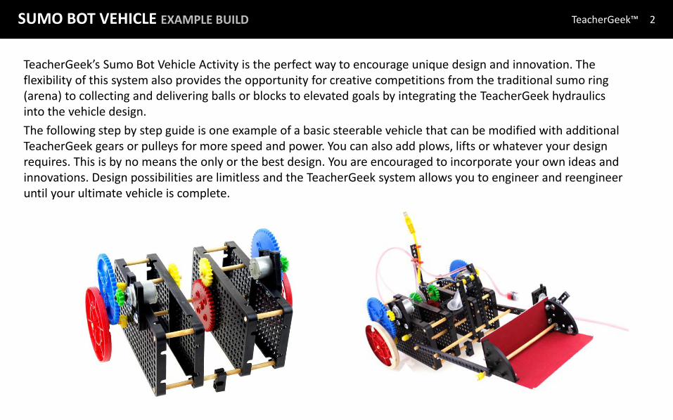
SUMO BOT VEHICLE EXAMPLE BUILD
TeacherGeek™ Sumo Bot Vehicle Application Guide © TeacherGeek™, 2011
SUMO BOT VEHICLE EXAMPLE BUILD TeacherGeek™
TeacherGeek’s Sumo Bot Vehicle Activity is the perfect way to encourage unique design and innovation. The flexibility of this system also provides the opportunity for creative competitions from the traditional sumo ring (arena) to collecting and delivering balls or blocks to elevated goals by integrating the TeacherGeek hydraulics into the vehicle design.
The following step by step guide is one example of a basic steerable vehicle that can be modified with additional TeacherGeek gears or pulleys for more speed and power. You can also add plows, lifts or whatever your design requires. This is by no means the only or the best design. You are encouraged to incorporate your own ideas and innovations. Design possibilities are limitless and the TeacherGeek system allows you to engineer and reengineer until your ultimate vehicle is complete.
2

SUMO BOT VEHICLE EXAMPLE BUILD TeacherGeek™ 3
The TeacherGeek Quick-Start Guide provides a great reference for techniques, tools and tips used to assure successful building.
Before beginning construction, take time to review this important information..
QUICK-START GUIDE
Click on this image to open the full PDF document.
SUMO BOT VEHICLE EXAMPLE BUILD TeacherGeek™ 4
A
B
D
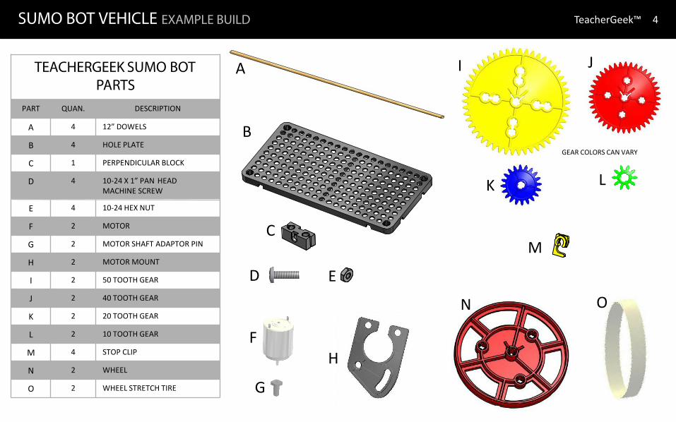
TEACHERGEEK SUMO BOT PARTS
PART QUAN. DESCRIPTION
A 4 12” DOWELS
B 4 HOLE PLATE
C 1 PERPENDICULAR BLOCK
D 4 10-24 X 1” PAN HEAD MACHINE SCREW
E 4 10-24 HEX NUT
F 2 MOTOR
G 2 MOTOR SHAFT ADAPTOR PIN
H 2 MOTOR MOUNT
I 2 50 TOOTH GEAR
J 2 40 TOOTH GEAR
K 2 20 TOOTH GEAR
L 2 10 TOOTH GEAR
M 4 STOP CLIP
N 2 WHEEL
O 2 WHEEL STRETCH TIRE
C
E
F
J
G
I
M
H
L K
O N
GEAR COLORS CAN VARY

SUMO BOT VEHICLE EXAMPLE BUILD TeacherGeek™ 5
CHASSIS ASSEMBLY Assemble the sides of the vehicle using two hole plates for each held together with two dowels in the top corner holes as shown.
Ream the bottom inside corner holes as shown. Reaming these four holes only allows you to freely insert the connecting dowel through the mid chassis. Yet, that dowel will be secured in the outside chassis corner unreamed holes.
Ream the inside bottom corner holes of both side assemblies. Do not ream the outside
bottom corner holes of both side assemblies.
The chassis sides are built using four hole plates and four dowels cut to 51 mm (~2”).
1
2

SUMO BOT VEHICLE EXAMPLE BUILD TeacherGeek™ 6
Cut 2 dowels 150 mm (5 7/8”) Slide dowels through the reamed corner holes of one
side and insert into unreamed holes of the other hole plate.
Slide the end hole of a perpendicular block on to one of the dowels so it is 19 mm (3/4”) from the hole plate as shown.
This establishes the front of the vehicle.
Slide the other ends of the dowels through the reamed holes of the other side and into the unreamed holes of the outside hole plate.
This completes the basic chassis for the vehicle.
CHASSIS ASSEMBLY
Reamed Holes
Unreamed Holes
3
4
5
SUMO BOT VEHICLE EXAMPLE BUILD TeacherGeek™ 7
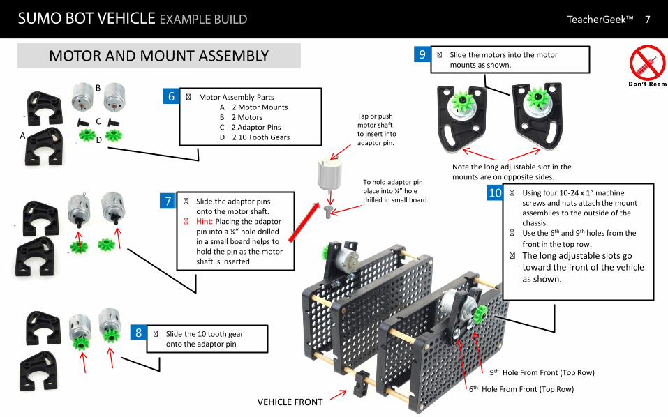
MOTOR AND MOUNT ASSEMBLY
7
� Motor Assembly Parts A 2 Motor Mounts B 2 Motors C 2 Adaptor Pins D 2 10 Tooth Gears
� Slide the 10 tooth gear onto the adaptor pin
� Slide the motors into the motor mounts as shown.
Note the long adjustable slot in the mounts are on opposite sides.
� Using four 10-24 x 1” machine screws and nuts attach the mount assemblies to the outside of the chassis.
� Use the 6th and 9th holes from the front in the top row.
� The long adjustable slots go toward the front of the vehicle as shown.
6th Hole From Front (Top Row)
A
B
D
C
� Slide the adaptor pins onto the motor shaft.
� Hint: Placing the adaptor pin into a ¼” hole drilled in a small board helps to hold the pin as the motor shaft is inserted.
9th Hole From Front (Top Row)
VEHICLE FRONT
Tap or push motor shaft to insert into adaptor pin.
To hold adaptor pin place into ¼” hole drilled in small board.
6
8
9
10

SUMO BOT VEHICLE EXAMPLE BUILD TeacherGeek™ 8
Cut two dowels 89 mm (3 ½”). Draw a pencil line 13 mm (1/2”)
from one end of each dowel. Install a TeacherGeek clips so
they align with pencil marks as shown.
Place two 50 tooth gears on a flat surface.
Insert the ends of the dowels through the center hole of the gears as shown.
Slide the other end of the dowel through the top row 7th hole from the back.
Repeat through the opposite side as shown.
7th Hole (including doweled corner hole)
Slide a 20 tooth gear on the end of each dowel.
Leave about 1/16” clearance so the gears spin freely.
11
13
14
12
GEARS, WHEELS AND AXLES
13 mm (~1/2”)

SUMO BOT VEHICLE EXAMPLE BUILD TeacherGeek™ 9
16
GEARS, WHEELS AND AXLES
Cut two dowels 102 mm (~4”). Draw a pencil line 29 mm (~1
1/8”) from one end of each dowel.
Install a TeacherGeek clips so they align with pencil marks as shown.
Slide the end of each dowel through the center of a wheel as shown.
Insert the dowel and wheel assembly into the same vertical row as the gear axle and four holes up from the bottom.
Four holes up seven holes from back of vehicle (Same vertical row as gear axle).
Slide a 40 tooth gear on the end of each dowel. Leave about 1/16” clearance so the wheel spins freely.
29 mm (~1 1/8”) 18
17 15
Back of Vehicle
Front of Vehicle

SUMO BOT VEHICLE EXAMPLE BUILD TeacherGeek™ 10
INSTALLING TRACTION TIRES
Coat the outside of the wheel with a common glue stick. When it becomes tacky, carefully stretch the tire over the
wheel. Adjust the tire so it is centered on the wheel .
MOTOR WIRING
Wiring of the motors depends on the type of controller used. If the TeacherGeek Total Controller is used, wiring instructions are
included in the Total Controller Guide. If other controllers are used, follow the appropriate wiring diagram.
19 20

SUMO BOT VEHICLE EXAMPLE BUILD TeacherGeek™ 11
TRY ADDING TEACHERGEEK HYDRAULICS

SUMO BOT VEHICLE EXAMPLE BUILD TeacherGeek™ 12
TEACHERGEEK PULLEY DRIVEN VEHICLE EXAMPLE