Embed Size (px)
Citation preview
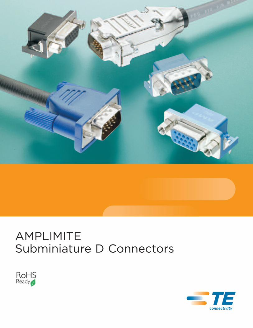
AMPLIMITESubminiature D Connectors
TEConnectivity
Catalog82068
Revise
d4-12
te.com
© 2012 Tyco Electronics Corporation, a TE Connectivity Ltd. Company. All Rights Reserved.
82068 LUG PDF 04/2012
TE Connectivity and the TE connectivity (logo) are trademarks. Other logos, product and/or company
names might be trademarks of their respective owners.
AMPLIMITESubminiatureDConnectors
2Catalog 82068 Dimensions are shown for Dimensions are in inches and Canada: +1 (905) 475-6222 UK: +44 (0) 800-267666Revised 4-12 reference purposes only. millimeters unless otherwise Mexico/C. Am.: +52 (0) 55-1106-0800 France: +33 (0) 1-3420-8686
Specifications subject specified. Latin/S. Am.: +54 (0) 11-4733-2200 Netherlands: +31 (0) 73-6246-999www.te.com to change. USA: +1 (800) 522-6752 Germany: +49 (0) 6251-133-1999 China: +86 (0) 400-820-6015
AMPLIMITE Subminiature D Connectors
DisclaimerWhile TE has made every reasonableeffort to ensure the accuracy of theinformation in this catalog, TE doesnot guarantee that it is error-free, nordoes TE make any other representation,warranty or guarantee that the informa-tion is accurate, correct, reliable orcurrent. TE reserves the right to makeany adjustments to the informationcontained herein at any time withoutnotice. TE expressly disclaims all impliedwarranties regarding the informationcontained herein, including, but notlimited to, any implied warranties ofmerchantability or fitness for a particularpurpose. The dimensions in this catalogare for reference purposes only andare subject to change without notice.Specifications are subject to changewithout notice. Consult TE for the latestdimensions and design specifications.© 2012, 2008, 2004, 2000, 1998, 1996,1995, 1994, 1993, 1992, 1988, 1984,1983 and 1981 Tyco ElectronicsCorporation. All Rights Reserved.AMP, AMPLIMITE, AMP-LATCH,AMP-O-LECTRIC, AMP-O-MATIC,AMPOMATOR, AMP-TY, ACTION PIN,CERTI-CRIMP, CERTI-LOK,CHAMPOMATOR, PRO-CRIMPER,TE Connectivity and the TE connectivity(logo) are trademarks of theTE Connectivity Ltd. family of companies.Other logos, product and Companynames mentioned herein may betrademarks of their respective owners.
Introduction
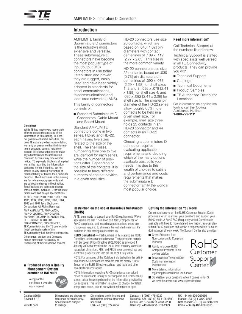
AMPLIMITE family ofSubminiature D connectorsis the industry’s mostextensive and versatile.These subminiature Dconnectors have becomethe most popular type ofinput/output (I/O)connectors in use today.Established and proven,they are rugged, easilyused and have been widelyadopted in standards forserial communications,telecommunications andlocal area networks (LANS).
This family of connectorsconsists of:
Standard Subminiature DConnectors, Cable Mountand Board Mount
Standard AMPLIMITEconnectors come in twoseries, HD-20 and HD-22,each having five sizesrelated to the size of theshell. The shell sizes,numbering from one to five,are identical for each series,while the number of posi-tions differ. Depending onthe size of the contacts, it ispossible to have differentnumbers of contact cavitiesin a given shell size.
HD-20 connectors use size20 contacts, which arebased on .040 [1.02] pindiameters with contactcenterlines of .109 x .112[2.77 x 2.85]. This size isthe more common variety.
HD-22 connectors use size22 contacts, based on .030[0.76] pin diameters oncenterlines of .090 x .078[2.29 x 1.98] for shell sizes1, 2 and 3; .095 x .078 [2.41x 1.98] for shell size 4; and.095 x .082 [2.41 x 2.08] forshell size 5. The smaller pindiameter of the HD-22 seriesallow roughly 65% morecontacts to be held in agiven shell size. Forexample, shell size threeholds 25 contacts in anHD-20 connector and 44contacts in an HD-22connector.
Choosing a subminiature Dconnector requiresevaluating applicationrequirements and decidingwhich of the many optionsavailable best suits yourneeds. It is due to thiswealth of choices to satisfyand performance and costsrequirements that makesthe subminiature Dconnector family the world’smost popular choice.
A copy of thecertificate is availableupon request
Produced under a QualityManagement Systemcertified to ISO 9001
ISO
Certified9001
Need more information?
Call Technical Support atthe numbers listed below.
Technical Support is staffedwith specialists well versedin all TE Connectivityproducts. They can provideyou with: Technical Support Catalogs Technical Documents Product Samples TE Authorized Distributor
LocationsFor information on applicationtooling call the ToolingAssistance Hotline:1-800-722-1111
Restriction on the use of Hazardous Substances(RoHS)At TE, we’re ready to support your RoHS requirements. We’veassessed more than 1.5 million end items/components forRoHS compliance, and issued new part numbers where anychange was required to eliminate the restricted materials. Partnumbers in this catalog are identified as:RoHS Compliant —Part numbers in this catalog are RoHSCompliant, unless marked otherwise. These products complywith European Union Directive 2002/95/EC as amended 1January 2006 that restricts the use of lead, mercury, cadmium,hexavalent chromium, PBB, and PBDE in certain electrical andelectronic products sold into the EU as of 1 July 2006.NOTE: For purposes of this Catalog, included within the defini-tion of RoHS Compliant are products that are clearly “Out ofScope” of the RoHS Directive such as hand tools and othernon-electrical accessories.NOTE: Information regarding RoHS compliance is providedbased on reasonable inquiry of our suppliers and represents ourcurrent actual knowledge based on the information provided byour suppliers. This information is subject to change. For latestcompliance status, refer to our website referenced at right.
Getting the Information You NeedOur comprehensive on-line RoHS Customer Support Centerprovides a forum to answer your questions and support yourRoHS needs. A RoHS FAQ (Frequently Asked Questions) isavailable with links to more detailed information. You can alsosubmit RoHS questions and receive a response within 24 hoursduring a normal work week. The Support Center also provides: Cross-Reference from
Non-compliant to CompliantProducts
Ability to browse RoHSCompliant Products in ouron-line catalog
Downloadable Technical DataCustomer InformationPresentation
More detailed informationregarding the definitions used above
So whatever your questions when it comes to RoHS,we have the answers at www.te.com/leadfree
RoHSCustomerSupportCenter
3Catalog 82068 Dimensions are shown for Dimensions are in inches and Canada: +1 (905) 475-6222 UK: +44 (0) 800-267666Revised 4-12 reference purposes only. millimeters unless otherwise Mexico/C. Am.: +52 (0) 55-1106-0800 France: +33 (0) 1-3420-8686
Specifications subject specified. Latin/S. Am.: +54 (0) 11-4733-2200 Netherlands: +31 (0) 73-6246-999www.te.com to change. USA: +1 (800) 522-6752 Germany: +49 (0) 6251-133-1999 China: +86 (0) 400-820-6015
AMPLIMITE Subminiature D Connectors
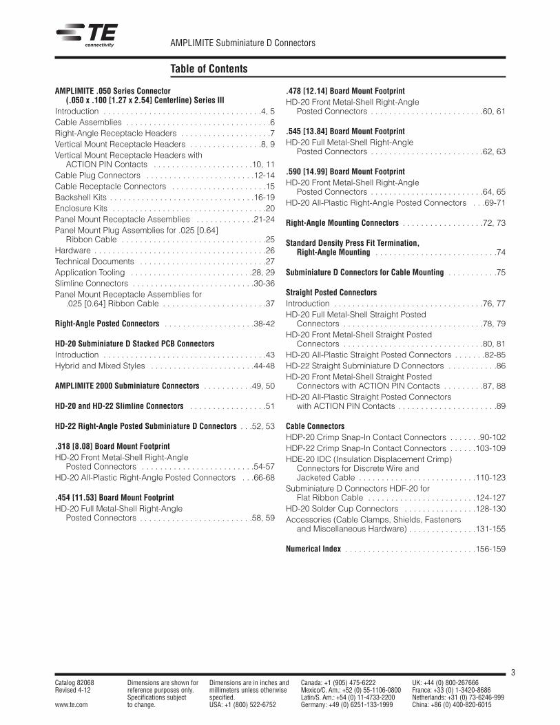
Table of Contents
AMPLIMITE .050 Series Connector(.050 x .100 [1.27 x 2.54] Centerline) Series III
Introduction . . . . . . . . . . . . . . . . . . . . . . . . . . . . . . . . . . .4, 5Cable Assemblies . . . . . . . . . . . . . . . . . . . . . . . . . . . . . . . .6Right-Angle Receptacle Headers . . . . . . . . . . . . . . . . . . . .7Vertical Mount Receptacle Headers . . . . . . . . . . . . . . . .8, 9Vertical Mount Receptacle Headers with
ACTION PIN Contacts . . . . . . . . . . . . . . . . . . . . . .10, 11Cable Plug Connectors . . . . . . . . . . . . . . . . . . . . . . . .12-14Cable Receptacle Connectors . . . . . . . . . . . . . . . . . . . . .15Backshell Kits . . . . . . . . . . . . . . . . . . . . . . . . . . . . . . . .16-19Enclosure Kits . . . . . . . . . . . . . . . . . . . . . . . . . . . . . . . . . .20Panel Mount Receptacle Assemblies . . . . . . . . . . . . .21-24Panel Mount Plug Assemblies for .025 [0.64]
Ribbon Cable . . . . . . . . . . . . . . . . . . . . . . . . . . . . . . . .25Hardware . . . . . . . . . . . . . . . . . . . . . . . . . . . . . . . . . . . . . .26Technical Documents . . . . . . . . . . . . . . . . . . . . . . . . . . . .27Application Tooling . . . . . . . . . . . . . . . . . . . . . . . . . . .28, 29Slimline Connectors . . . . . . . . . . . . . . . . . . . . . . . . . . .30-36Panel Mount Receptacle Assemblies for
.025 [0.64] Ribbon Cable . . . . . . . . . . . . . . . . . . . . . . .37
Right-Angle Posted Connectors . . . . . . . . . . . . . . . . . . . .38-42
HD-20 Subminiature D Stacked PCB ConnectorsIntroduction . . . . . . . . . . . . . . . . . . . . . . . . . . . . . . . . . . . .43Hybrid and Mixed Styles . . . . . . . . . . . . . . . . . . . . . . .44-48
AMPLIMITE 2000 Subminiature Connectors . . . . . . . . . . .49, 50
HD-20 and HD-22 Slimline Connectors . . . . . . . . . . . . . . . . .51
HD-22 Right-Angle Posted Subminiature D Connectors . . .52, 53
.318 [8.08] Board Mount FootprintHD-20 Front Metal-Shell Right-Angle
Posted Connectors . . . . . . . . . . . . . . . . . . . . . . . . .54-57HD-20 All-Plastic Right-Angle Posted Connectors . . .66-68
.454 [11.53] Board Mount FootprintHD-20 Full Metal-Shell Right-Angle
Posted Connectors . . . . . . . . . . . . . . . . . . . . . . . . .58, 59
.478 [12.14] Board Mount FootprintHD-20 Front Metal-Shell Right-Angle
Posted Connectors . . . . . . . . . . . . . . . . . . . . . . . . .60, 61
.545 [13.84] Board Mount FootprintHD-20 Full Metal-Shell Right-Angle
Posted Connectors . . . . . . . . . . . . . . . . . . . . . . . . .62, 63
.590 [14.99] Board Mount FootprintHD-20 Front Metal-Shell Right-Angle
Posted Connectors . . . . . . . . . . . . . . . . . . . . . . . . .64, 65HD-20 All-Plastic Right-Angle Posted Connectors . . .69-71
Right-Angle Mounting Connectors . . . . . . . . . . . . . . . . . .72, 73
Standard Density Press Fit Termination,Right-Angle Mounting . . . . . . . . . . . . . . . . . . . . . . . . . . .74
Subminiature D Connectors for Cable Mounting . . . . . . . . . . .75
Straight Posted ConnectorsIntroduction . . . . . . . . . . . . . . . . . . . . . . . . . . . . . . . . .76, 77HD-20 Full Metal-Shell Straight Posted
Connectors . . . . . . . . . . . . . . . . . . . . . . . . . . . . . . .78, 79HD-20 Front Metal-Shell Straight Posted
Connectors . . . . . . . . . . . . . . . . . . . . . . . . . . . . . . .80, 81HD-20 All-Plastic Straight Posted Connectors . . . . . . .82-85HD-22 Straight Subminiature D Connectors . . . . . . . . . . .86HD-20 Front Metal-Shell Straight Posted
Connectors with ACTION PIN Contacts . . . . . . . . .87, 88HD-20 All-Plastic Straight Posted Connectors
with ACTION PIN Contacts . . . . . . . . . . . . . . . . . . . . . .89
Cable ConnectorsHDP-20 Crimp Snap-In Contact Connectors . . . . . . .90-102HDP-22 Crimp Snap-In Contact Connectors . . . . . .103-109HDE-20 IDC (Insulation Displacement Crimp)
Connectors for Discrete Wire andJacketed Cable . . . . . . . . . . . . . . . . . . . . . . . . . .110-123
Subminiature D Connectors HDF-20 forFlat Ribbon Cable . . . . . . . . . . . . . . . . . . . . . . . .124-127
HD-20 Solder Cup Connectors . . . . . . . . . . . . . . . .128-130Accessories (Cable Clamps, Shields, Fasteners
and Miscellaneous Hardware) . . . . . . . . . . . . . . .131-155
Numerical Index . . . . . . . . . . . . . . . . . . . . . . . . . . . . .156-159
4Catalog 82068 Dimensions are shown for Dimensions are in inches and Canada: +1 (905) 475-6222 UK: +44 (0) 800-267666Revised 4-12 reference purposes only. millimeters unless otherwise Mexico/C. Am.: +52 (0) 55-1106-0800 France: +33 (0) 1-3420-8686
Specifications subject specified. Latin/S. Am.: +54 (0) 11-4733-2200 Netherlands: +31 (0) 73-6246-999www.te.com to change. USA: +1 (800) 522-6752 Germany: +49 (0) 6251-133-1999 China: +86 (0) 400-820-6015
AMPLIMITE Subminiature D Connectors
AMPLIMITE .050 Series Connector(.050 x .100 [1.27 x 2.54] Centerline) Series III
AMPL
IMIT
E.0
50Se
ries
Conn
ecto
rs,S
erie
sIII
Product Facts Compatible with SCSI-2,
SCSI-3, EIA RS-232,ISO-11569*, HIPPI, IPI-2and IEE 802.3 MII standards
High-density D typeinterface
20 through 100 contactpositions
Tab plug contacts andtuning-fork receptaclecontacts, with reliable two-point (redundant) contact;contact normal force is notdependent on plastichousing support
Excellent EMI/RFI protection Shields mate before
contacts, with ground matingfirst and breaking last
Squeeze-to-release latchesor jackscrew hardware
Board connectorscompatible with standardthru-hole flow solder andsurface-mount reflow solderprocesses (Series III)
Recognized under theComponent Program ofUnderwritersLaboratories Inc.,File No. E28476
Listed and complies withUL 1863, CommunicationCircuit AccessoriesFile No. E81956
Certified by CanadianStandardsAssociation,File No. 1088108(LR 7189A-207)
Produced under a QualityManagementSystem certifiedto ISO 9001
A copy of thecertificate is availableupon request
R
R
R
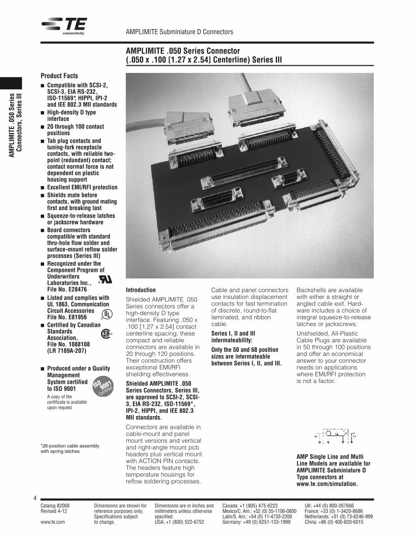
Introduction
Shielded AMPLIMITE .050Series connectors offer ahigh-density D typeinterface. Featuring .050 x.100 [1.27 x 2.54] contactcenterline spacing, thesecompact and reliableconnectors are available in20 through 120 positions.Their construction offersexceptional EMI/RFIshielding effectiveness.
Shielded AMPLIMITE .050Series Connectors, Series III,are approved to SCSI-2, SCSI-3, EIA RS-232, ISO-11569*,IPI-2, HIPPI, and IEE 802.3MII standards.
Connectors are available incable-mount and panelmount versions and verticaland right-angle mount pcbheaders plus vertical mountwith ACTION PIN contacts.The headers feature hightemperature housings forreflow soldering processes.
Cable and panel connectorsuse insulation displacementcontacts for fast terminationof discrete, round-to-flatlaminated, and ribboncable.
Series I, II and IIIintermateability:
Only the 50 and 68 positionsizes are intermateablebetween Series I, II, and III.
Backshells are availablewith either a straight orangled cable exit. Hard-ware includes a choice ofintegral squeeze-to-releaselatches or jackscrews.
Unshielded, All-PlasticCable Plugs are availablein 50 through 100 positionsand offer an economicalanswer to your connectorneeds on applicationswhere EMI/RFI protectionis not a factor.
ISO
Certified9001
*26-position cable assemblywith spring latches
AMP Single Line and MultiLine Models are available forAMPLIMITE Subminiature DType connectors atwww.te.com/simulation.
5Catalog 82068 Dimensions are shown for Dimensions are in inches and Canada: +1 (905) 475-6222 UK: +44 (0) 800-267666Revised 4-12 reference purposes only. millimeters unless otherwise Mexico/C. Am.: +52 (0) 55-1106-0800 France: +33 (0) 1-3420-8686
Specifications subject specified. Latin/S. Am.: +54 (0) 11-4733-2200 Netherlands: +31 (0) 73-6246-999www.te.com to change. USA: +1 (800) 522-6752 Germany: +49 (0) 6251-133-1999 China: +86 (0) 400-820-6015
AMPLIMITE Subminiature D Connectors
AMPLIMITE .050 Series Connector(.050 x .100 [1.27 x 2.54] Centerline) Series III (Continued)
AMPLIM
ITE.050
SeriesConnectors,Series
III
Product Facts Compact design, profile for
the right-angle header1.230 x .588 [31.24 x14.94], vertical header1.230 x .433 [31.24 x11.00], right-angle stackedheaders 1.230 x .803[31.24 x 20.40]
Housings and covers madeof UL 94V-0 rated thermo-plastic
Header footprint for right-angle and stackedconfigurations is .100 x.050 [2.54 x 1.27]staggered centerlines
Header footprint for verticalconfiguration is .100 x .075[2.54 x 1.90] staggeredcenterlines
Right-angle and stackedheaders feature integralboardlocks for positiveboard retention andgrounding
Vertical headers feature 8below the board, retentivecontact legs for mechanicalretention before and aftersoldering
Vertical headers featurepolarized grounding poststo assure correct header-to-board orientation
Stacked headers reduceoverall total header volumeby 48% and PC board areaby 38%
Stacked headers offeroptional contact shield foradditional EMI/RFIprotection
Plugs preloaded withinsulation displacementcontacts (IDC) provide fast,reliable and economicalterminations
Choice of three keyingpositions, plus non-keyedinserts for assuranceagainst mismatch mating
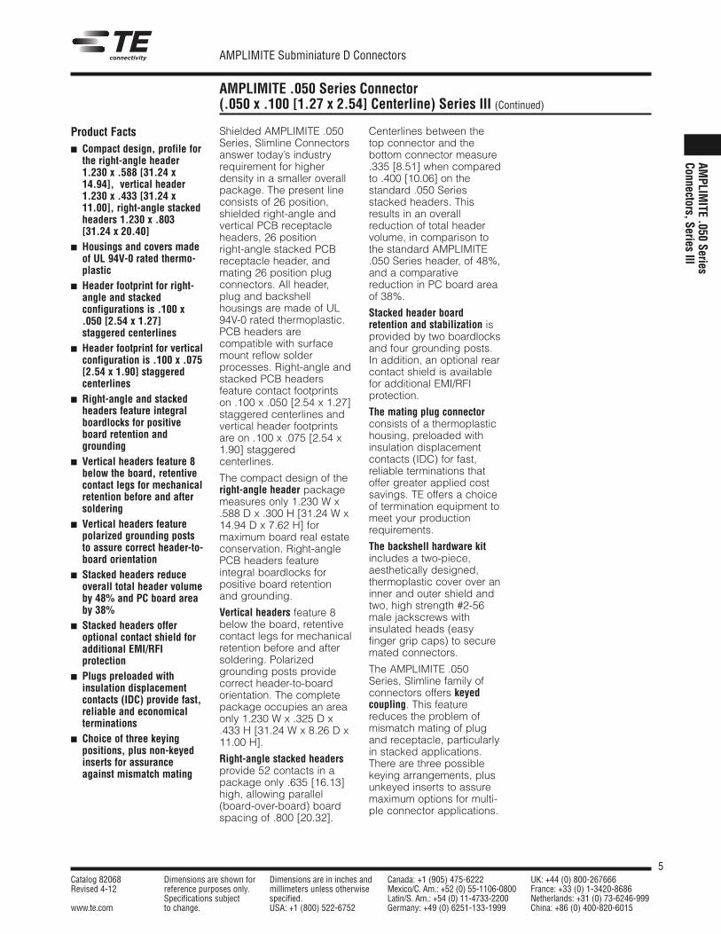
Shielded AMPLIMITE .050Series, Slimline Connectorsanswer today’s industryrequirement for higherdensity in a smaller overallpackage. The present lineconsists of 26 position,shielded right-angle andvertical PCB receptacleheaders, 26 positionright-angle stacked PCBreceptacle header, andmating 26 position plugconnectors. All header,plug and backshellhousings are made of UL94V-0 rated thermoplastic.PCB headers arecompatible with surfacemount reflow solderprocesses. Right-angle andstacked PCB headersfeature contact footprintson .100 x .050 [2.54 x 1.27]staggered centerlines andvertical header footprintsare on .100 x .075 [2.54 x1.90] staggeredcenterlines.
The compact design of theright-angle header packagemeasures only 1.230 W x.588 D x .300 H [31.24 W x14.94 D x 7.62 H] formaximum board real estateconservation. Right-anglePCB headers featureintegral boardlocks forpositive board retentionand grounding.
Vertical headers feature 8below the board, retentivecontact legs for mechanicalretention before and aftersoldering. Polarizedgrounding posts providecorrect header-to-boardorientation. The completepackage occupies an areaonly 1.230 W x .325 D x.433 H [31.24 W x 8.26 D x11.00 H].
Right-angle stacked headersprovide 52 contacts in apackage only .635 [16.13]high, allowing parallel(board-over-board) boardspacing of .800 [20.32].
Centerlines between thetop connector and thebottom connector measure.335 [8.51] when comparedto .400 [10.06] on thestandard .050 Seriesstacked headers. Thisresults in an overallreduction of total headervolume, in comparison tothe standard AMPLIMITE.050 Series header, of 48%,and a comparativereduction in PC board areaof 38%.
Stacked header boardretention and stabilization isprovided by two boardlocksand four grounding posts.In addition, an optional rearcontact shield is availablefor additional EMI/RFIprotection.
The mating plug connectorconsists of a thermoplastichousing, preloaded withinsulation displacementcontacts (IDC) for fast,reliable terminations thatoffer greater applied costsavings. TE offers a choiceof termination equipment tomeet your productionrequirements.
The backshell hardware kitincludes a two-piece,aesthetically designed,thermoplastic cover over aninner and outer shield andtwo, high strength #2-56male jackscrews withinsulated heads (easyfinger grip caps) to securemated connectors.
The AMPLIMITE .050Series, Slimline family ofconnectors offers keyedcoupling. This featurereduces the problem ofmismatch mating of plugand receptacle, particularlyin stacked applications.There are three possiblekeying arrangements, plusunkeyed inserts to assuremaximum options for multi-ple connector applications.
6Catalog 82068 Dimensions are shown for Dimensions are in inches and Canada: +1 (905) 475-6222 UK: +44 (0) 800-267666Revised 4-12 reference purposes only. millimeters unless otherwise Mexico/C. Am.: +52 (0) 55-1106-0800 France: +33 (0) 1-3420-8686
Specifications subject specified. Latin/S. Am.: +54 (0) 11-4733-2200 Netherlands: +31 (0) 73-6246-999www.te.com to change. USA: +1 (800) 522-6752 Germany: +49 (0) 6251-133-1999 China: +86 (0) 400-820-6015
AMPLIMITE Subminiature D Connectors
Note: All part numbers are RoHS compliant.
AMPLIMITE .050 Series Cable Assemblies, Series III
AMPL
IMIT
E.0
50Se
ries
Conn
ecto
rs,S
erie
sIII
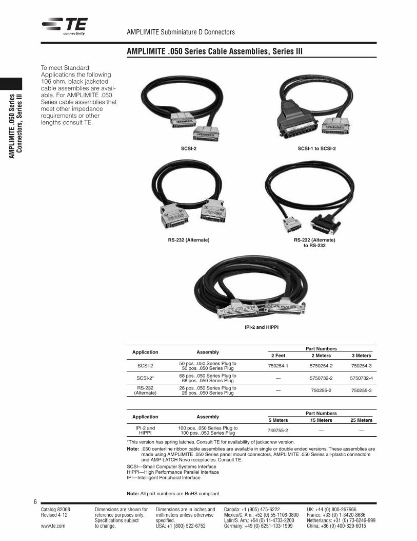
To meet StandardApplications the following106 ohm, black jacketedcable assemblies are avail-able. For AMPLIMITE .050Series cable assemblies thatmeet other impedancerequirements or otherlengths consult TE.
Part NumbersApplication Assembly
2 Feet 2 Meters 3 Meters
50 pos. .050 Series Plug toSCSI-2 50 pos. .050 Series Plug 750254-1 5750254-2 750254-3
68 pos. .050 Series Plug toSCSI-2* 68 pos. .050 Series Plug — 5750732-2 5750732-4
RS-232 26 pos. .050 Series Plug to(Alternate) 26 pos. .050 Series Plug — 750255-2 750255-3
Part NumbersApplication Assembly
5 Meters 15 Meters 25 Meters
IPI-2 and 100 pos. .050 Series Plug toHIPPI 100 pos. .050 Series Plug 749755-2 — —
*This version has spring latches. Consult TE for availability of jackscrew version.Note: .050 centerline ribbon cable assemblies are available in single or double ended versions. These assemblies are
made using AMPLIMITE .050 Series panel mount connectors, AMPLIMITE .050 Series all-plastic connectorsand AMP-LATCH Novo receptacles. Consult TE.
SCSI—Small Computer Systems InterfaceHIPPI—High Performance Parallel InterfaceIPI—Intelligent Peripheral Interface
RS-232 (Alternate)
IPI-2 and HIPPI
SCSI-1 to SCSI-2SCSI-2
RS-232 (Alternate)to RS-232
7Catalog 82068 Dimensions are shown for Dimensions are in inches and Canada: +1 (905) 475-6222 UK: +44 (0) 800-267666Revised 4-12 reference purposes only. millimeters unless otherwise Mexico/C. Am.: +52 (0) 55-1106-0800 France: +33 (0) 1-3420-8686
Specifications subject specified. Latin/S. Am.: +54 (0) 11-4733-2200 Netherlands: +31 (0) 73-6246-999www.te.com to change. USA: +1 (800) 522-6752 Germany: +49 (0) 6251-133-1999 China: +86 (0) 400-820-6015
AMPLIMITE Subminiature D Connectors
Note: All part numbers are RoHS compliant.
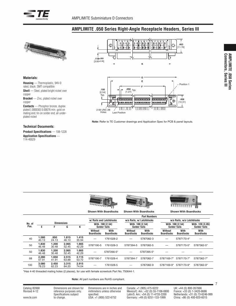
AMPLIMITE .050 Series Right-Angle Receptacle Headers, Series III
AMPLIM
ITE.050
SeriesConnectors,Series
III
Materials:Housing — Thermoplastic, 94V-0rated, black. SMT compatibleShell —Steel, plated bright nickel overcopperBracket — Zinc, plated nickel overcopperContacts —Phosphor bronze, duplexplated [.000030] 0.00076 min. gold onmating end; tin on solder end; all under-plated nickel
Technical Documents:Product Specifications — 108-1228Application Specifications —114-40029
.463[11.76]
.118±.003[3.00±0.08]
K
.406[10.31]
2-56 UNC 2BHoles
.100[2.54]Typ.
G
E
FPosition 1
Last Position
.050[1.27]
Typ.
ShownWith Boardlocks ShownWith Boardlocks ShownWith Boardlocks
Part Numbersw/ Rails and Latchblocks w/o Rails, w/ Latchblocks w/o Rails, w/o Latchblocks
No. of Dimensions With .100 [2.54] With .100 [2.54] With .100 [2.54] With .120 [3.05]Pos. E F G K Solder Tails Solder Tails Solder Tails Solder Tails
Without With Without With Without With WithBoardlocks Boardlocks Boardlocks Boardlocks Boardlocks Boardlocks Boardlocks
40 1.580 .950 1.815 1.415 — 1761028-2 — 5787082-3 — 5787170-4* —40.13 24.13 46.10 35.94
50 1.830 1.200 2.065 1.665 5787190-5 1761028-3 5787394-5 5787082-5 — 5787170-5* 5787362-5*46.48 30.48 52.45 42.29
50 1.830 1.200 2.065 1.665 — 5787266-5* — 5787395-5* — — —46.48 30.48 52.45 42.29
68 2.280 1.650 2.515 2.115 5787190-7 1761028-4 5787394-7 5787082-7 5787169-7* 5787170-7* 5787362-7*57.91 41.91 63.88 53.72
100 3.080 2.450 3.315 2.915 — 1761028-5 — 5787082-9 5787169-9* 5787170-9* 5787362-9*78.23 62.23 84.20 74.04
*Has 4-40 threaded mating holes (2 places), for use with female screwlock Part No. 750644-1.
Note: Refer to TE Customer drawings and Application Spec for PCB & panel layouts.
8Catalog 82068 Dimensions are shown for Dimensions are in inches and Canada: +1 (905) 475-6222 UK: +44 (0) 800-267666Revised 4-12 reference purposes only. millimeters unless otherwise Mexico/C. Am.: +52 (0) 55-1106-0800 France: +33 (0) 1-3420-8686
Specifications subject specified. Latin/S. Am.: +54 (0) 11-4733-2200 Netherlands: +31 (0) 73-6246-999www.te.com to change. USA: +1 (800) 522-6752 Germany: +49 (0) 6251-133-1999 China: +86 (0) 400-820-6015
AMPLIMITE Subminiature D Connectors
Note: All part numbers are RoHS compliant.
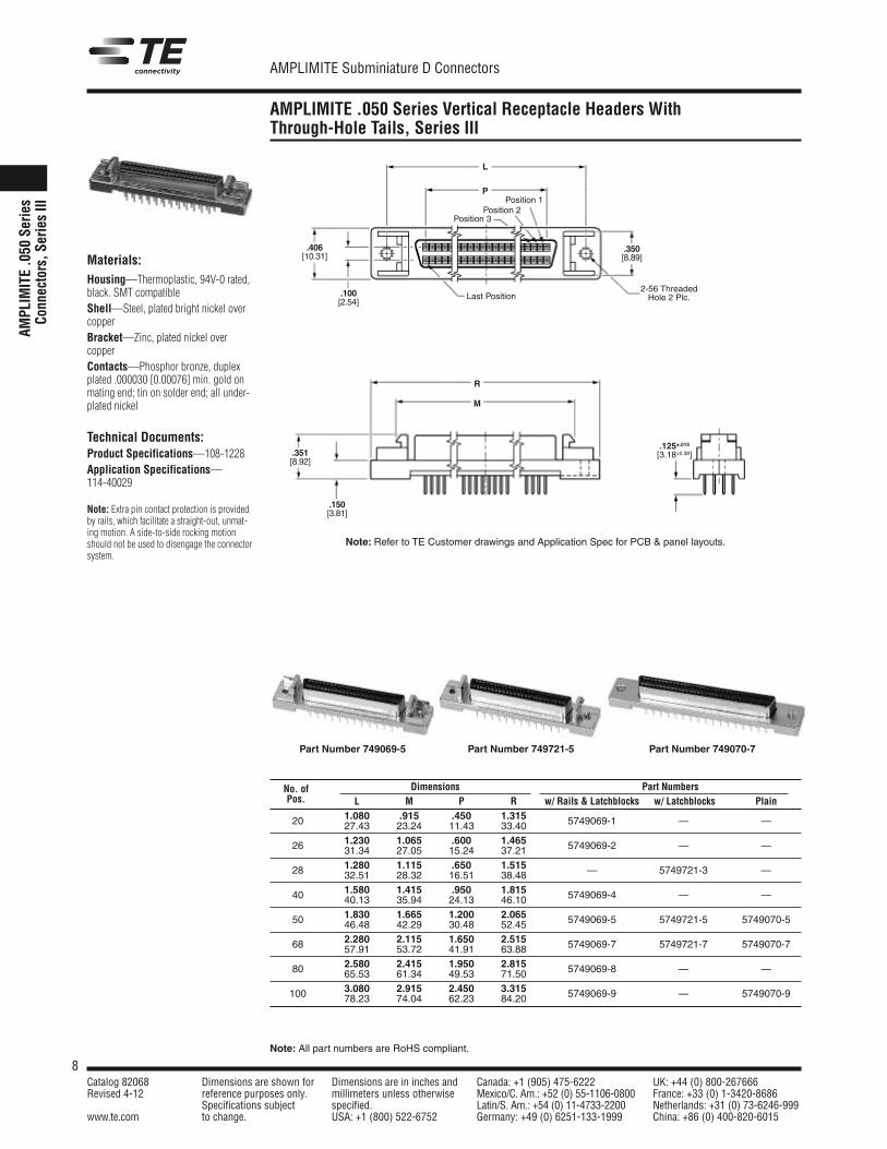
AMPLIMITE .050 Series Vertical Receptacle Headers WithThrough-Hole Tails, Series III
AMPL
IMIT
E.0
50Se
ries
Conn
ecto
rs,S
erie
sIII
Last Position.100[2.54]
.350[8.89]
.406[10.31]
L
P
2-56 ThreadedHole 2 Plc.
Position 1Position 2
Position 3
Materials:Housing—Thermoplastic, 94V-0 rated,black. SMT compatibleShell—Steel, plated bright nickel overcopperBracket—Zinc, plated nickel overcopperContacts—Phosphor bronze, duplexplated .000030 [0.00076] min. gold onmating end; tin on solder end; all under-plated nickel
Technical Documents:Product Specifications—108-1228Application Specifications—114-40029
Note: Extra pin contact protection is providedby rails, which facilitate a straight-out, unmat-ing motion. A side-to-side rocking motionshould not be used to disengage the connectorsystem.
.125±.015[3.18±0.38].351
[8.92]
.150[3.81]
R
M
Part Number 749069-5
No. of Dimensions Part NumbersPos. L M P R w/ Rails & Latchblocks w/ Latchblocks Plain
20 1.080 .915 .450 1.315 5749069-1 — —27.43 23.24 11.43 33.40
26 1.230 1.065 .600 1.465 5749069-2 — —31.34 27.05 15.24 37.21
28 1.280 1.115 .650 1.515 — 5749721-3 —32.51 28.32 16.51 38.48
40 1.580 1.415 .950 1.815 5749069-4 — —40.13 35.94 24.13 46.10
50 1.830 1.665 1.200 2.065 5749069-5 5749721-5 5749070-546.48 42.29 30.48 52.45
68 2.280 2.115 1.650 2.515 5749069-7 5749721-7 5749070-757.91 53.72 41.91 63.88
80 2.580 2.415 1.950 2.815 5749069-8 — —65.53 61.34 49.53 71.50
100 3.080 2.915 2.450 3.315 5749069-9 — 5749070-978.23 74.04 62.23 84.20
Note: Refer to TE Customer drawings and Application Spec for PCB & panel layouts.
Part Number 749721-5 Part Number 749070-7
9Catalog 82068 Dimensions are shown for Dimensions are in inches and Canada: +1 (905) 475-6222 UK: +44 (0) 800-267666Revised 4-12 reference purposes only. millimeters unless otherwise Mexico/C. Am.: +52 (0) 55-1106-0800 France: +33 (0) 1-3420-8686
Specifications subject specified. Latin/S. Am.: +54 (0) 11-4733-2200 Netherlands: +31 (0) 73-6246-999www.te.com to change. USA: +1 (800) 522-6752 Germany: +49 (0) 6251-133-1999 China: +86 (0) 400-820-6015
AMPLIMITE Subminiature D Connectors
Note: All part numbers are RoHS compliant.
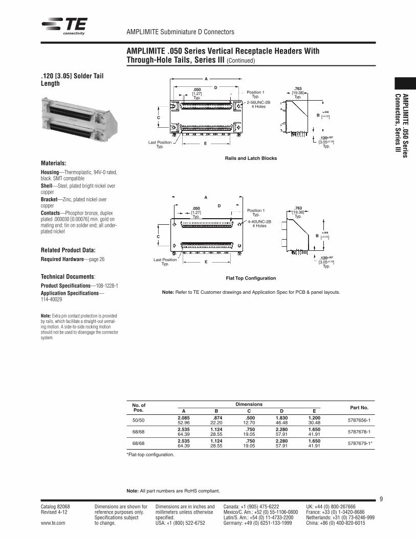
AMPLIMITE .050 Series Vertical Receptacle Headers WithThrough-Hole Tails, Series III (Continued)
AMPLIM
ITE.050
SeriesConnectors,Series
III
No. of DimensionsPart No.Pos. A B C D E
2.085 .874 .500 1.830 1.20050/50 52.96 22.20 12.70 46.48 30.48 5787656-1
2.535 1.124 .750 2.280 1.65068/68 64.39 28.55 19.05 57.91 41.91 5787678-1
2.535 1.124 .750 2.280 1.65068/68 64.39 28.55 19.05 57.91 41.91*5787679-1*
*Flat-top configuration.
E
E
.120 [3.05] Solder TailLength
Materials:Housing—Thermoplastic, 94V-0 rated,black. SMT compatibleShell—Steel, plated bright nickel overcopperBracket—Zinc, plated nickel overcopperContacts—Phosphor bronze, duplexplated .000030 [0.00076] min. gold onmating end; tin on solder end; all under-plated nickel
Related Product Data:Required Hardware—page 26
Technical Documents:Product Specifications—108-1228-1Application Specifications—114-40029
Note: Extra pin contact protection is providedby rails, which facilitate a straight-out unmat-ing motion. A side-to-side rocking motionshould not be used to disengage the connectorsystem.
C
C
A
A
D
D
.120±.007[3.05±0.18]Typ.
.120±.007[3.05±0.18]Typ.
.050[1.27]Typ.
.050[1.27]Typ.
.763[19.38]Typ.
.763[19.38]Typ.
Position 1Typ.
Position 1Typ.
Last PositionTyp.
Last PositionTyp.
2-56UNC-2B4 Holes
4-40UNC-2B4 Holes
±.008
[±0.20]
±.008
[±0.20]
B
B
Rails and Latch Blocks
Flat Top Configuration
Note: Refer to TE Customer drawings and Application Spec for PCB & panel layouts.
10Catalog 82068 Dimensions are shown for Dimensions are in inches and Canada: +1 (905) 475-6222 UK: +44 (0) 800-267666Revised 4-12 reference purposes only. millimeters unless otherwise Mexico/C. Am.: +52 (0) 55-1106-0800 France: +33 (0) 1-3420-8686
Specifications subject specified. Latin/S. Am.: +54 (0) 11-4733-2200 Netherlands: +31 (0) 73-6246-999www.te.com to change. USA: +1 (800) 522-6752 Germany: +49 (0) 6251-133-1999 China: +86 (0) 400-820-6015
AMPLIMITE Subminiature D Connectors
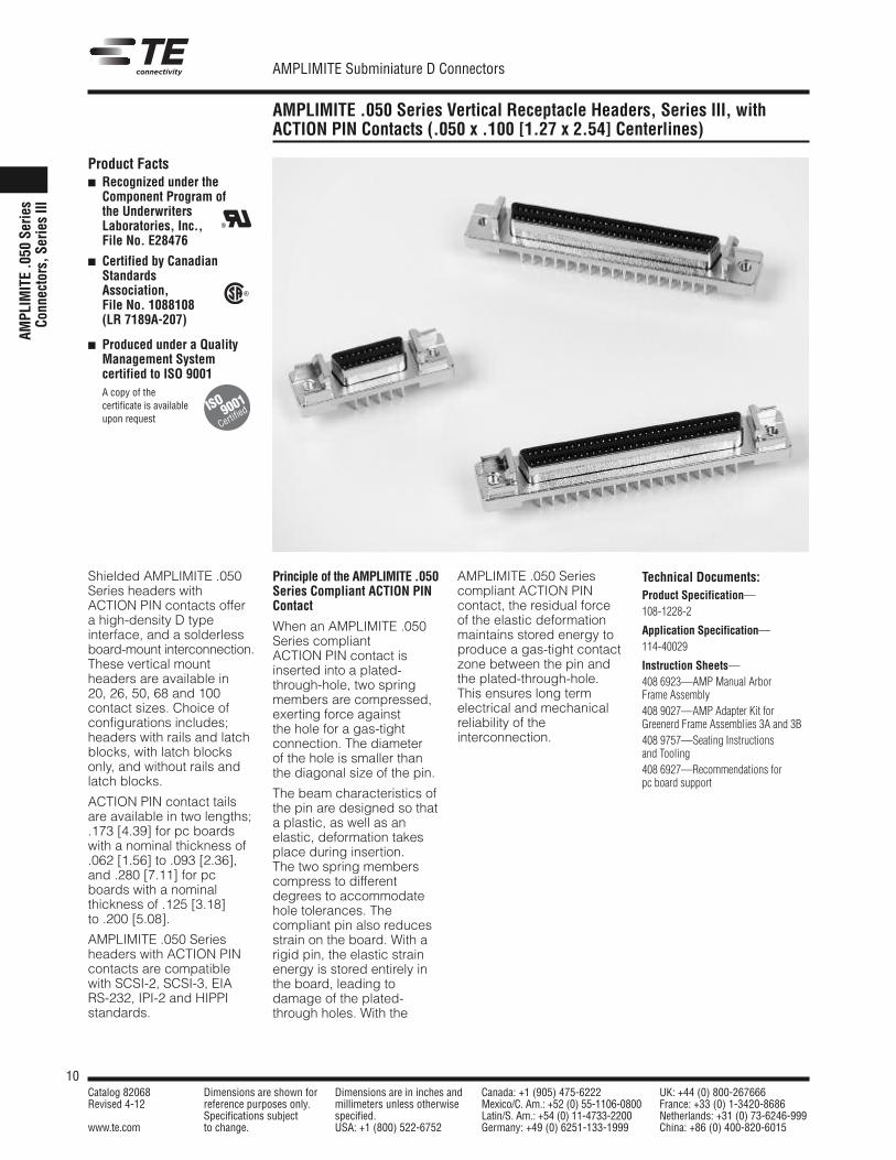
AMPLIMITE .050 Series Vertical Receptacle Headers, Series III, withACTION PIN Contacts (.050 x .100 [1.27 x 2.54] Centerlines)
AMPL
IMIT
E.0
50Se
ries
Conn
ecto
rs,S
erie
sIII
Shielded AMPLIMITE .050Series headers withACTION PIN contacts offera high-density D typeinterface, and a solderlessboard-mount interconnection.These vertical mountheaders are available in20, 26, 50, 68 and 100contact sizes. Choice ofconfigurations includes;headers with rails and latchblocks, with latch blocksonly, and without rails andlatch blocks.
ACTION PIN contact tailsare available in two lengths;.173 [4.39] for pc boardswith a nominal thickness of.062 [1.56] to .093 [2.36],and .280 [7.11] for pcboards with a nominalthickness of .125 [3.18]to .200 [5.08].
AMPLIMITE .050 Seriesheaders with ACTION PINcontacts are compatiblewith SCSI-2, SCSI-3, EIARS-232, IPI-2 and HIPPIstandards.
Principle of the AMPLIMITE .050Series Compliant ACTION PINContact
When an AMPLIMITE .050Series compliantACTION PIN contact isinserted into a plated-through-hole, two springmembers are compressed,exerting force againstthe hole for a gas-tightconnection. The diameterof the hole is smaller thanthe diagonal size of the pin.
The beam characteristics ofthe pin are designed so thata plastic, as well as anelastic, deformation takesplace during insertion.The two spring memberscompress to differentdegrees to accommodatehole tolerances. Thecompliant pin also reducesstrain on the board. With arigid pin, the elastic strainenergy is stored entirely inthe board, leading todamage of the plated-through holes. With the
AMPLIMITE .050 Seriescompliant ACTION PINcontact, the residual forceof the elastic deformationmaintains stored energy toproduce a gas-tight contactzone between the pin andthe plated-through-hole.This ensures long termelectrical and mechanicalreliability of theinterconnection.
Product Facts Recognized under the
Component Program ofthe UnderwritersLaboratories, Inc.,File No. E28476
Certified by CanadianStandardsAssociation,File No. 1088108(LR 7189A-207)
Produced under a QualityManagement Systemcertified to ISO 9001
A copy of thecertificate is availableupon request
R
R
Technical Documents:Product Specification—108-1228-2
Application Specification—114-40029
Instruction Sheets—408 6923—AMP Manual ArborFrame Assembly408 9027—AMP Adapter Kit forGreenerd Frame Assemblies 3A and 3B408 9757—Seating Instructionsand Tooling408 6927—Recommendations forpc board support
ISO
Certified9001
11Catalog 82068 Dimensions are shown for Dimensions are in inches and Canada: +1 (905) 475-6222 UK: +44 (0) 800-267666Revised 4-12 reference purposes only. millimeters unless otherwise Mexico/C. Am.: +52 (0) 55-1106-0800 France: +33 (0) 1-3420-8686
Specifications subject specified. Latin/S. Am.: +54 (0) 11-4733-2200 Netherlands: +31 (0) 73-6246-999www.te.com to change. USA: +1 (800) 522-6752 Germany: +49 (0) 6251-133-1999 China: +86 (0) 400-820-6015
AMPLIMITE Subminiature D Connectors
Note: All part numbers are RoHS compliant.
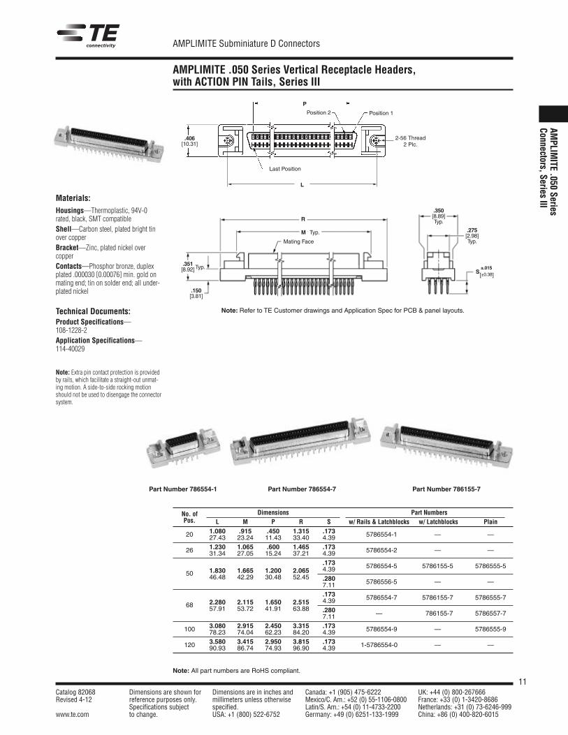
AMPLIMITE .050 Series Vertical Receptacle Headers,with ACTION PIN Tails, Series III
AMPLIM
ITE.050
SeriesConnectors,Series
III
2-56 Thread2 Plc.
L
Last Position
Position 1Position 2
.406[10.31]
P
Mating Face
Typ.
Typ..351[8.92]
.150[3.81]
.275[2.98]Typ.
.350[8.89]Typ.R
M
S±.015
[±0.38]
Materials:Housings—Thermoplastic, 94V-0rated, black, SMT compatibleShell—Carbon steel, plated bright tinover copperBracket—Zinc, plated nickel overcopperContacts—Phosphor bronze, duplexplated .000030 [0.00076] min. gold onmating end; tin on solder end; all under-plated nickel
Technical Documents:Product Specifications—108-1228-2Application Specifications—114-40029
Note: Extra pin contact protection is providedby rails, which facilitate a straight-out unmat-ing motion. A side-to-side rocking motionshould not be used to disengage the connectorsystem.
No. of Dimensions Part NumbersPos. L M P R S w/ Rails & Latchblocks w/ Latchblocks Plain
20 1.080 .915 .450 1.315 .173 5786554-1 — —27.43 23.24 11.43 33.40 4.39
26 1.230 1.065 .600 1.465 .173 5786554-2 — —31.34 27.05 15.24 37.21 4.39.173 5786554-5 5786155-5 5786555-5
50 1.830 1.665 1.200 2.065 4.3946.48 42.29 30.48 52.45 .280 5786556-5 — —7.11
.173 5786554-7 5786155-7 5786555-768 2.280 2.115 1.650 2.515 4.39
57.91 53.72 41.91 63.88 .280 — 786155-7 5786557-77.11
100 3.080 2.915 2.450 3.315 .173 5786554-9 — 5786555-978.23 74.04 62.23 84.20 4.39
120 3.580 3.415 2.950 3.815 .173 1-5786554-0 — —90.93 86.74 74.93 96.90 4.39
Note: Refer to TE Customer drawings and Application Spec for PCB & panel layouts.
Part Number 786554-1 Part Number 786554-7 Part Number 786155-7
12Catalog 82068 Dimensions are shown for Dimensions are in inches and Canada: +1 (905) 475-6222 UK: +44 (0) 800-267666Revised 4-12 reference purposes only. millimeters unless otherwise Mexico/C. Am.: +52 (0) 55-1106-0800 France: +33 (0) 1-3420-8686
Specifications subject specified. Latin/S. Am.: +54 (0) 11-4733-2200 Netherlands: +31 (0) 73-6246-999www.te.com to change. USA: +1 (800) 522-6752 Germany: +49 (0) 6251-133-1999 China: +86 (0) 400-820-6015
AMPLIMITE Subminiature D Connectors
Note: All part numbers are RoHS compliant.
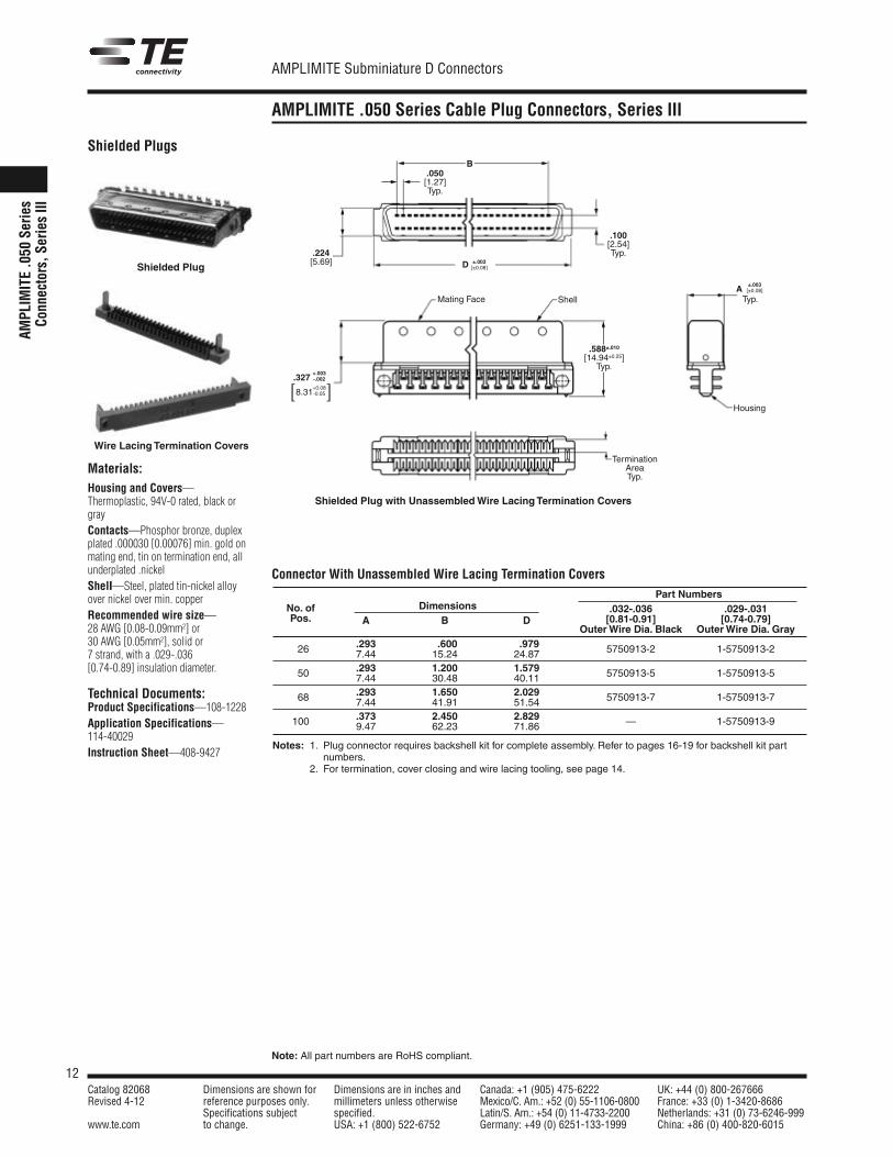
AMPLIMITE .050 Series Cable Plug Connectors, Series III
AMPL
IMIT
E.0
50Se
ries
Conn
ecto
rs,S
erie
sIII
Materials:Housing and Covers—Thermoplastic, 94V-0 rated, black orgrayContacts—Phosphor bronze, duplexplated .000030 [0.00076] min. gold onmating end, tin on termination end, allunderplated .nickelShell—Steel, plated tin-nickel alloyover nickel over min. copperRecommended wire size—28 AWG [0.08-0.09mm2] or30 AWG [0.05mm2], solid or7 strand, with a .029-.036[0.74-0.89] insulation diameter.
Technical Documents:Product Specifications—108-1228Application Specifications—114-40029Instruction Sheet—408-9427
B
Housing
.050[1.27]Typ.
.224[5.69]
.100[2.54]Typ.
+.003.327 -.002
+0.08[8.31-0.05]
.588±.010[14.94±0.25]Typ.
Mating Face Shell
±.003D [±0.08]
±.003A [±0.08]
Typ.
TerminationAreaTyp.
Shielded Plugs
Shielded Plug with UnassembledWire Lacing Termination Covers
Shielded Plug
Wire Lacing Termination Covers
Part NumbersNo. of Dimensions .032-.036 .029-.031Pos. A B D [0.81-0.91] [0.74-0.79]
OuterWire Dia. Black OuterWire Dia. Gray.293 .600 .97926 7.44 15.24 24.87 5750913-2 1-5750913-2
.293 1.200 1.57950 7.44 30.48 40.11 5750913-5 1-5750913-5
.293 1.650 2.02968 7.44 41.91 51.54 5750913-7 1-5750913-7
.373 2.450 2.829100 9.47 62.23 71.86 — 1-5750913-9
Notes: 1. Plug connector requires backshell kit for complete assembly. Refer to pages 16-19 for backshell kit partnumbers.
2. For termination, cover closing and wire lacing tooling, see page 14.
Connector With Unassembled Wire Lacing Termination Covers
13Catalog 82068 Dimensions are shown for Dimensions are in inches and Canada: +1 (905) 475-6222 UK: +44 (0) 800-267666Revised 4-12 reference purposes only. millimeters unless otherwise Mexico/C. Am.: +52 (0) 55-1106-0800 France: +33 (0) 1-3420-8686
Specifications subject specified. Latin/S. Am.: +54 (0) 11-4733-2200 Netherlands: +31 (0) 73-6246-999www.te.com to change. USA: +1 (800) 522-6752 Germany: +49 (0) 6251-133-1999 China: +86 (0) 400-820-6015
AMPLIMITE Subminiature D Connectors
Note: All part numbers are RoHS compliant.
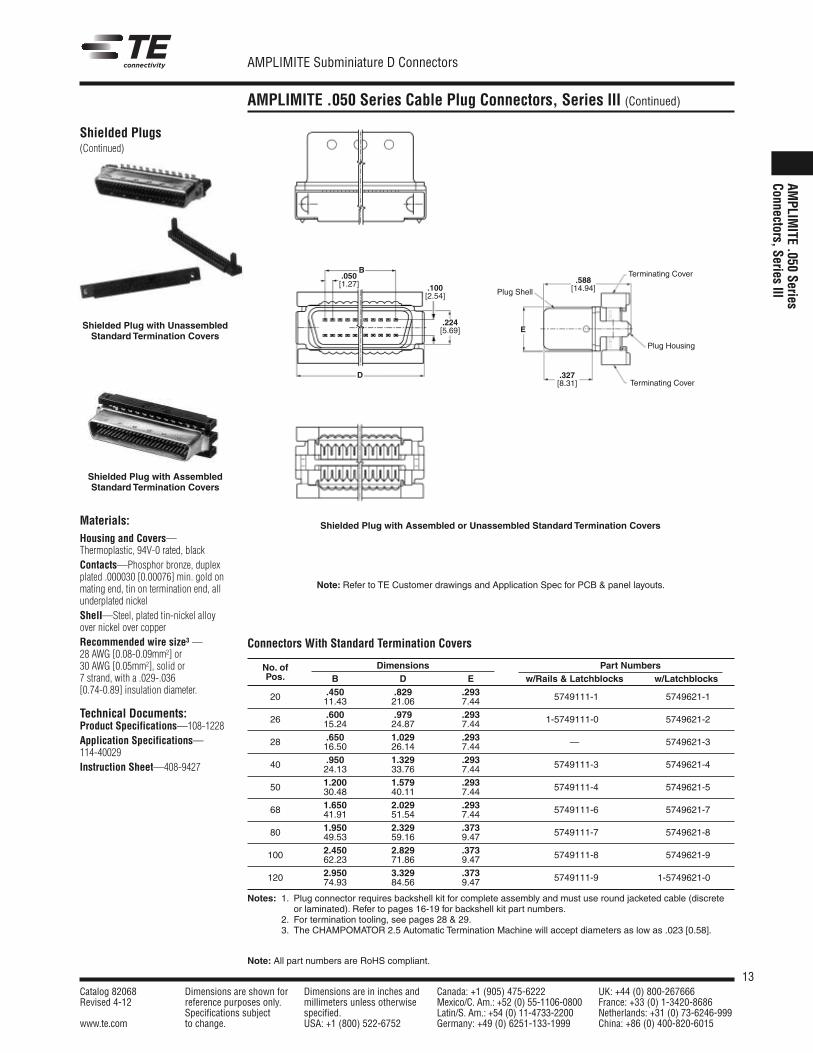
AMPLIMITE .050 Series Cable Plug Connectors, Series III (Continued)
AMPLIM
ITE.050
SeriesConnectors,Series
III
Shielded Plugs(Continued)
.050[1.27]
Terminating Cover
.327[8.31]
E
D
B
.100[2.54]
.224[5.69]
.588[14.94]
Plug Housing
Plug Shell
Terminating Cover
Shielded Plug with UnassembledStandard Termination Covers
Shielded Plug with Assembled or Unassembled Standard Termination Covers
No. of Dimensions Part NumbersPos. B D E w/Rails & Latchblocks w/Latchblocks
.450 .829 .29320 11.43 21.06 7.44 5749111-1 5749621-1
.600 .979 .29326 15.24 24.87 7.44 1-5749111-0 5749621-2
.650 1.029 .29328 16.50 26.14 7.44 — 5749621-3
.950 1.329 .29340 24.13 33.76 7.44 5749111-3 5749621-4
1.200 1.579 .29350 30.48 40.11 7.44 5749111-4 5749621-5
1.650 2.029 .29368 41.91 51.54 7.44 5749111-6 5749621-7
1.950 2.329 .37380 49.53 59.16 9.47 5749111-7 5749621-8
2.450 2.829 .373100 62.23 71.86 9.47 5749111-8 5749621-9
2.950 3.329 .373120 74.93 84.56 9.47 5749111-9 1-5749621-0
Notes: 1. Plug connector requires backshell kit for complete assembly and must use round jacketed cable (discreteor laminated). Refer to pages 16-19 for backshell kit part numbers.
2. For termination tooling, see pages 28 & 29.3. The CHAMPOMATOR 2.5 Automatic Termination Machine will accept diameters as low as .023 [0.58].
Shielded Plug with AssembledStandard Termination Covers
Materials:Housing and Covers—Thermoplastic, 94V-0 rated, blackContacts—Phosphor bronze, duplexplated .000030 [0.00076] min. gold onmating end, tin on termination end, allunderplated nickelShell—Steel, plated tin-nickel alloyover nickel over copperRecommended wire size3 —28 AWG [0.08-0.09mm2] or30 AWG [0.05mm2], solid or7 strand, with a .029-.036[0.74-0.89] insulation diameter.
Technical Documents:Product Specifications—108-1228Application Specifications—114-40029Instruction Sheet—408-9427
Connectors With Standard Termination Covers
Note: Refer to TE Customer drawings and Application Spec for PCB & panel layouts.
14Catalog 82068 Dimensions are shown for Dimensions are in inches and Canada: +1 (905) 475-6222 UK: +44 (0) 800-267666Revised 4-12 reference purposes only. millimeters unless otherwise Mexico/C. Am.: +52 (0) 55-1106-0800 France: +33 (0) 1-3420-8686
Specifications subject specified. Latin/S. Am.: +54 (0) 11-4733-2200 Netherlands: +31 (0) 73-6246-999www.te.com to change. USA: +1 (800) 522-6752 Germany: +49 (0) 6251-133-1999 China: +86 (0) 400-820-6015
AMPLIMITE Subminiature D Connectors
Note: All part numbers are RoHS compliant.
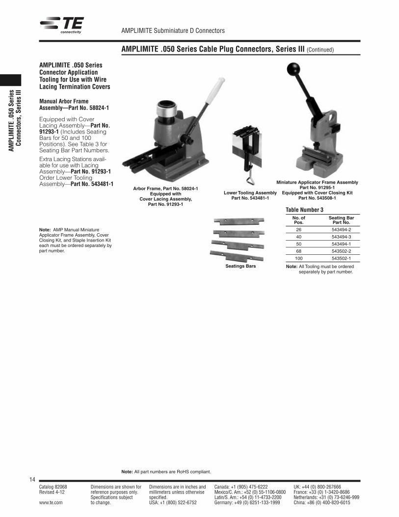
AMPLIMITE .050 Series Cable Plug Connectors, Series III (Continued)
AMPL
IMIT
E.0
50Se
ries
Conn
ecto
rs,S
erie
sIII
AMPLIMITE .050 SeriesConnector ApplicationTooling for Use with WireLacing Termination Covers
Manual Arbor FrameAssembly—Part No. 58024-1
Equipped with CoverLacing Assembly—Part No.91293-1 (Includes SeatingBars for 50 and 100Positions). See Table 3 forSeating Bar Part Numbers.
Extra Lacing Stations avail-able for use with LacingAssembly—Part No. 91293-1Order Lower ToolingAssembly—Part No. 543481-1
Arbor Frame, Part No. 58024-1Equipped with
Cover Lacing Assembly,Part No. 91293-1
Seatings Bars
No. of Seating BarPos. Part No.
26 543494-2
40 543494-3
50 543494-1
68 543502-2
100 543502-1
Note: All Tooling must be orderedseparately by part number.
Table Number 3
Miniature Applicator Frame AssemblyPart No. 91295-1
Equipped with Cover Closing KitPart No. 543508-1
Note: AMP Manual MiniatureApplicator Frame Assembly, CoverClosing Kit, and Staple Insertion Kiteach must be ordered separately bypart number.
Lower Tooling AssemblyPart No. 543481-1
15Catalog 82068 Dimensions are shown for Dimensions are in inches and Canada: +1 (905) 475-6222 UK: +44 (0) 800-267666Revised 4-12 reference purposes only. millimeters unless otherwise Mexico/C. Am.: +52 (0) 55-1106-0800 France: +33 (0) 1-3420-8686
Specifications subject specified. Latin/S. Am.: +54 (0) 11-4733-2200 Netherlands: +31 (0) 73-6246-999www.te.com to change. USA: +1 (800) 522-6752 Germany: +49 (0) 6251-133-1999 China: +86 (0) 400-820-6015
AMPLIMITE Subminiature D Connectors
Note: All part numbers are RoHS compliant.
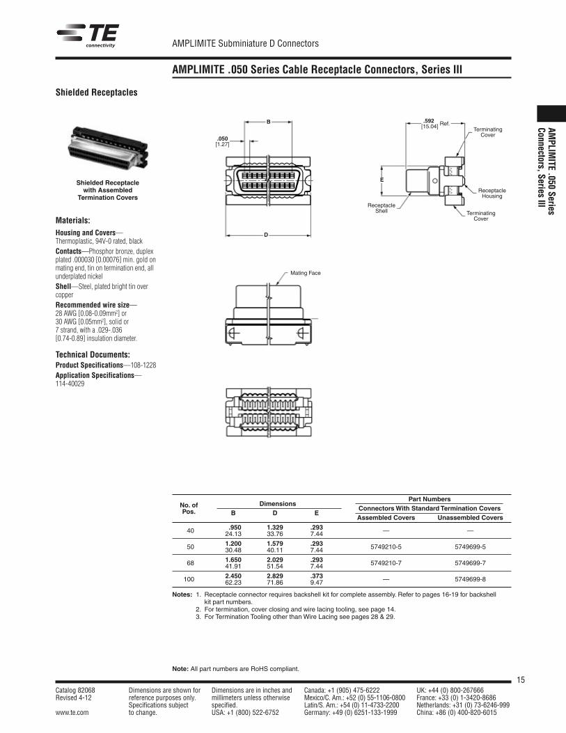
AMPLIMITE .050 Series Cable Receptacle Connectors, Series III
AMPLIM
ITE.050
SeriesConnectors,Series
III
Materials:Housing and Covers—Thermoplastic, 94V-0 rated, blackContacts—Phosphor bronze, duplexplated .000030 [0.00076] min. gold onmating end, tin on termination end, allunderplated nickelShell—Steel, plated bright tin overcopperRecommended wire size—28 AWG [0.08-0.09mm2] or30 AWG [0.05mm2], solid or7 strand, with a .029-.036[0.74-0.89] insulation diameter.
Technical Documents:Product Specifications—108-1228Application Specifications—114-40029
Shielded Receptacles
Shielded Receptaclewith Assembled
Termination Covers
B
D
.592[15.04] Ref.
E
TerminatingCover
ReceptacleHousing
ReceptacleShell
.050[1.27]
TerminatingCover
Mating Face
Part NumbersNo. of Dimensions
ConnectorsWith Standard Termination CoversPos. B D EAssembled Covers Unassembled Covers
.950 1.329 .29340 24.13 33.76 7.44 — —
1.200 1.579 .29350 30.48 40.11 7.44 5749210-5 5749699-5
1.650 2.029 .29368 41.91 51.54 7.44 5749210-7 5749699-7
2.450 2.829 .373100 62.23 71.86 9.47 — 5749699-8
Notes: 1. Receptacle connector requires backshell kit for complete assembly. Refer to pages 16-19 for backshellkit part numbers.
2. For termination, cover closing and wire lacing tooling, see page 14.3. For Termination Tooling other than Wire Lacing see pages 28 & 29.
16Catalog 82068 Dimensions are shown for Dimensions are in inches and Canada: +1 (905) 475-6222 UK: +44 (0) 800-267666Revised 4-12 reference purposes only. millimeters unless otherwise Mexico/C. Am.: +52 (0) 55-1106-0800 France: +33 (0) 1-3420-8686
Specifications subject specified. Latin/S. Am.: +54 (0) 11-4733-2200 Netherlands: +31 (0) 73-6246-999www.te.com to change. USA: +1 (800) 522-6752 Germany: +49 (0) 6251-133-1999 China: +86 (0) 400-820-6015
AMPLIMITE Subminiature D Connectors
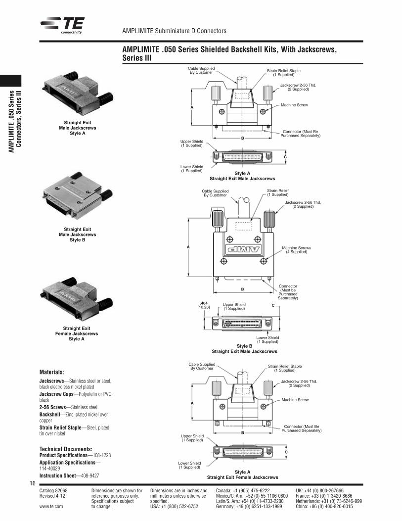
AMPLIMITE .050 Series Shielded Backshell Kits, With Jackscrews,Series III
AMPL
IMIT
E.0
50Se
ries
Conn
ecto
rs,S
erie
sIII
Materials:Jackscrews—Stainless steel or steel,black electroless nickel platedJackscrew Caps—Polyolefin or PVC,black2-56 Screws—Stainless steelBackshell—Zinc, plated nickel overcopperStrain Relief Staple—Steel, platedtin over nickel
Technical Documents:Product Specifications—108-1228Application Specifications—114-40029Instruction Sheet—408-9427
Straight ExitMale Jackscrews
Style A
Straight ExitMale Jackscrews
Style B
Style AStraight Exit Male Jackscrews
Style BStraight Exit Male Jackscrews
Straight ExitFemale Jackscrews
Style A
Style AStraight Exit Female Jackscrews
A
B
C
Cable SuppliedBy Customer Strain Relief Staple
(1 Supplied)
Jackscrew 2-56 Thd.(2 Supplied)
Machine Screw
Connector (Must BePurchased Separately)
Upper Shield(1 Supplied)
Lower Shield(1 Supplied)
A
B
C
Cable SuppliedBy Customer Strain Relief Staple
(1 Supplied)
Jackscrew 2-56 Thd.(2 Supplied)
Machine Screw
Connector (Must BePurchased Separately)
Upper Shield(1 Supplied)
A
B
C
Cable SuppliedBy Customer
Connector(Must bePurchasedSeparately)
.404[10.26]
Strain Relief(1 Supplied)
Jackscrew 2-56 Thd.(2 Supplied)
Machine Screws(4 Supplied)
Upper Shield(1 Supplied)
Lower Shield(1 Supplied)
Lower Shield(1 Supplied)
17Catalog 82068 Dimensions are shown for Dimensions are in inches and Canada: +1 (905) 475-6222 UK: +44 (0) 800-267666Revised 4-12 reference purposes only. millimeters unless otherwise Mexico/C. Am.: +52 (0) 55-1106-0800 France: +33 (0) 1-3420-8686
Specifications subject specified. Latin/S. Am.: +54 (0) 11-4733-2200 Netherlands: +31 (0) 73-6246-999www.te.com to change. USA: +1 (800) 522-6752 Germany: +49 (0) 6251-133-1999 China: +86 (0) 400-820-6015
AMPLIMITE Subminiature D Connectors
Note: All part numbers are RoHS compliant.
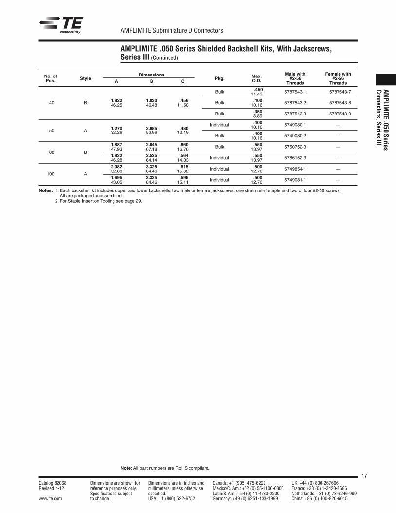
AMPLIMITE .050 Series Shielded Backshell Kits, With Jackscrews,Series III (Continued)
AMPLIM
ITE.050
SeriesConnectors,Series
III
No. of Dimensions Max. Male with Female with
Pos. StyleA B C
Pkg. O.D. #2-56 #2-56Threads Threads
.450Bulk 11.43 5787543-1 1-5787543-7
40 B 1.822 1.830 .456 .40046.25 46.48 11.58 Bulk 10.16 5787543-2 1-5787543-8
.350Bulk 8.89 5787543-3 1-5787543-9
.400
50 A 1.270 2.085 .480Individual 10.16 5749080-1 —
32.26 52.96 12.19 .400Bulk 10.16 5749080-2 —
1.887 2.645 .660 .550
68 B47.93 67.18 16.76 Bulk 13.97 5750752-3 —
1.822 2.525 .564 .55046.28 64.14 14.33 Individual 13.97 5786152-3 —
2.082 3.325 .615 .500
100 A52.88 84.46 15.62 Individual 12.70 5749854-1 —
1.695 3.325 .595 .50043.05 84.46 15.11 Individual 12.70 5749081-1 —
Notes: 1. Each backshell kit includes upper and lower backshells, two male or female jackscrews, one strain relief staple and two or four #2-56 screws.All are packaged unassembled.
Notes: 2. For Staple Insertion Tooling see page 29.
18Catalog 82068 Dimensions are shown for Dimensions are in inches and Canada: +1 (905) 475-6222 UK: +44 (0) 800-267666Revised 4-12 reference purposes only. millimeters unless otherwise Mexico/C. Am.: +52 (0) 55-1106-0800 France: +33 (0) 1-3420-8686
Specifications subject specified. Latin/S. Am.: +54 (0) 11-4733-2200 Netherlands: +31 (0) 73-6246-999www.te.com to change. USA: +1 (800) 522-6752 Germany: +49 (0) 6251-133-1999 China: +86 (0) 400-820-6015
AMPLIMITE Subminiature D Connectors
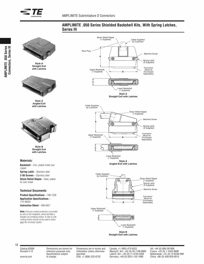
AMPLIMITE .050 Series Shielded Backshell Kits, With Spring Latches,Series III
AMPL
IMITE.0
50Se
ries
Conn
ectors,S
eriesIII
Materials:Backshell—Zinc, plated nickel overcopperSpring Latch—Stainless steel2-56 Screws—Stainless steelStrain Relief Staple—Steel, platedtin over nickel
Technical Documents:Product Specifications—108-1228Application Specifications—114-40029Instruction Sheet—408-9427
Note: Extra pin contact protection is providedby rails on the receptacle, which facilitate astraight-out unmating motion. A side-to-siderocking motion should not be used to disen-gage the connector system.
Style AStraight Exitwith Latches
Style AStraight Exit with Latches
Style BStraight Exitwith Latches
Style BStraight Exit with Latches
Style AAngled Exitwith Latches
Style AAngled Exit with Latches
C
Upper Backshell,(1 Supplied)
A
Cable Suppliedby Customer
B
Connector(Must bePurchasedSeparately)
Spring Latch(2 Supplied)
Strain Relief Staple(1 Supplied)
Lower Backshell(1 Supplied)
Rear PlugMachine Screw
C
Upper Backshell(1 Supplied)
A
Cable Suppliedby Customer
B
Connector(Must bePurchasedSeparately)
Spring Latch(2 Supplied)
Machine Screw
Strain Relief Staple(1 Supplied)
Lower Backshell(1 Supplied)
C
Upper Backshell(1 Supplied)
A
Cable Suppliedby Customer
B
Connector(Must bePurchasedSeparately)
Spring Latch(2 Supplied)
Strain Relief Staple(1 Supplied)
Lower Backshell(1 Supplied)
Machine Screw
19Catalog 82068 Dimensions are shown for Dimensions are in inches and Canada: +1 (905) 475-6222 UK: +44 (0) 800-267666Revised 4-12 reference purposes only. millimeters unless otherwise Mexico/C. Am.: +52 (0) 55-1106-0800 France: +33 (0) 1-3420-8686
Specifications subject specified. Latin/S. Am.: +54 (0) 11-4733-2200 Netherlands: +31 (0) 73-6246-999www.te.com to change. USA: +1 (800) 522-6752 Germany: +49 (0) 6251-133-1999 China: +86 (0) 400-820-6015
AMPLIMITE Subminiature D Connectors
Note: All part numbers are RoHS compliant.
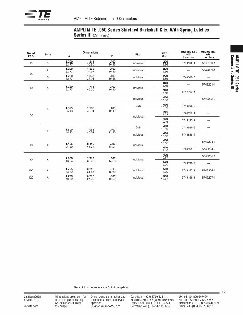
AMPLIMITE .050 Series Shielded Backshell Kits, With Spring Latches,Series III (Continued)
AMPLIM
ITE.050
SeriesConnectors,Series
III
Straight Exit Angled ExitNo. of StyleDimensions
Pkg. Max. with withPos. A B C O.D. Latches Latches
1.290 1.215 .400 .27020 A 32.77 30.86 10.16 Individual 6.86 5749190-1 5749199-1
A 1.290 1.365 .400 .270
2632.77 34.67 10.16 Individual 6.86 — 5749609-1
1.290 1.335 .400 .270B 32.77 33.91 10.16 Individual 6.86 749608-2 —
.3201.290 1.715 .400 8.13 — 5749201-1
40 A 32.77 43.56 10.16 Individual.3208.13 5749192-1 —
.400Individual 10.16 — 5749202-2
.400
A 1.395 1.965 .480Bulk 10.16 5749202-3 —
35.43 49.91 12.19 .3559.02 5749193-1 —
50 Individual.40010.16 5749193-2 —
.4801.800 1.965 .492
Bulk 12.19 5749889-3 —B 45.72 49.91 12.50 .480Individual 12.18 5749889-4 —
.4001.405 2.415 .520 10.16 — 5749204-1
68 A 35.69 61.34 13.21 Individual.44011.18 5749195-2 5749204-2
.4201.600 2.715 .565 10.67 — 5749205-1
80 A 40.64 68.96 14.35 Individual.50012.70 749196-2 —
1.725 3.215 .615 .500100 A 43.82 81.66 15.62 Individual 12.70 5749197-1 5749206-1
1.725 3.715 .665 .550120 A 43.82 94.36 16.89 Individual 13.97 5749198-1 5749207-1
20Catalog 82068 Dimensions are shown for Dimensions are in inches and Canada: +1 (905) 475-6222 UK: +44 (0) 800-267666Revised 4-12 reference purposes only. millimeters unless otherwise Mexico/C. Am.: +52 (0) 55-1106-0800 France: +33 (0) 1-3420-8686
Specifications subject specified. Latin/S. Am.: +54 (0) 11-4733-2200 Netherlands: +31 (0) 73-6246-999www.te.com to change. USA: +1 (800) 522-6752 Germany: +49 (0) 6251-133-1999 China: +86 (0) 400-820-6015
AMPLIMITE Subminiature D Connectors
Note: All part numbers are RoHS compliant.
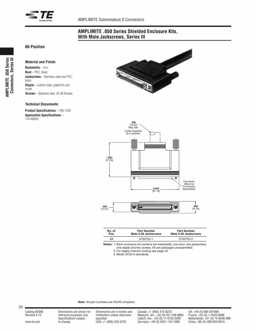
AMPLIMITE .050 Series Shielded Enclosure Kits,With Male Jackscrews, Series III
AMPL
IMITE.0
50Se
ries
Conn
ectors,S
eriesIII
68-Position
Material and Finish:Backshells—ZincBoot—PVC, blackJackscrews—Stainless steel and PVC,blackStaple—Carbon steel, plated tin overnickelScrews—Stainless steel, #2-56 threads
Technical Documents:
Product Specifications—108-1228Application Specifications—114-40029
Notes: 1. Each enclosure kit contains two backshells, one boot, two jackscrews,one staple and two screws. All are packaged unassembled.
2. For staple insertion tooling see page 29.3. Meets SCSI-3 standards.
Connector(Must bePurchasedSeparately)
.550[13.97]Max.Dia.
1.887[47.93]
.660[16.76]
Cable Suppliedby Customer
2.645[67.18]
.520[13.21]
No. of Part Number Part NumberPos. Male 2-56 Jackscrews Male 4-40 Jackscrews
68 5750752-1 5750752-2
21Catalog 82068 Dimensions are shown for Dimensions are in inches and Canada: +1 (905) 475-6222 UK: +44 (0) 800-267666Revised 4-12 reference purposes only. millimeters unless otherwise Mexico/C. Am.: +52 (0) 55-1106-0800 France: +33 (0) 1-3420-8686
Specifications subject specified. Latin/S. Am.: +54 (0) 11-4733-2200 Netherlands: +31 (0) 73-6246-999www.te.com to change. USA: +1 (800) 522-6752 Germany: +49 (0) 6251-133-1999 China: +86 (0) 400-820-6015
AMPLIMITE Subminiature D Connectors
Note: All part numbers are RoHS compliant.
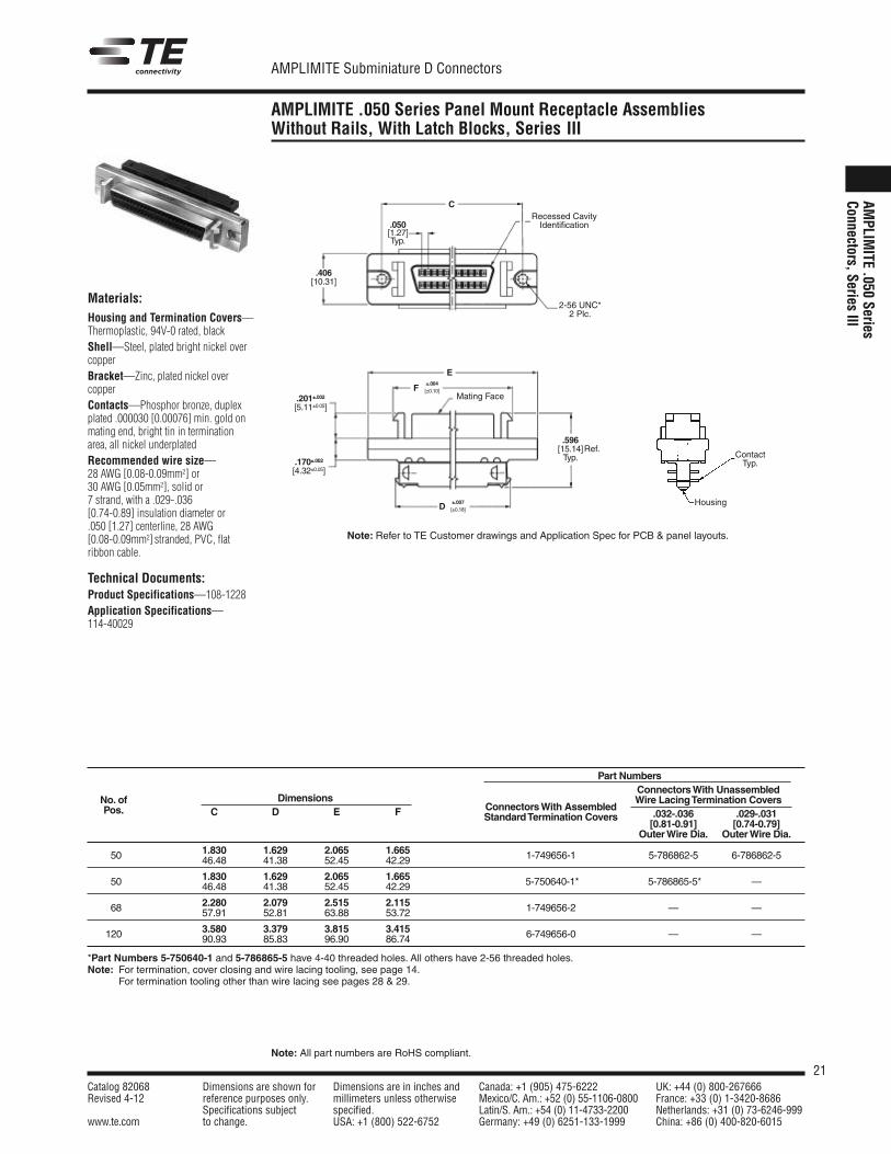
AMPLIMITE .050 Series Panel Mount Receptacle AssembliesWithout Rails, With Latch Blocks, Series III
AMPLIM
ITE.050
SeriesConnectors,Series
III
Materials:Housing and Termination Covers—Thermoplastic, 94V-0 rated, blackShell—Steel, plated bright nickel overcopperBracket—Zinc, plated nickel overcopperContacts—Phosphor bronze, duplexplated .000030 [0.00076] min. gold onmating end, bright tin in terminationarea, all nickel underplatedRecommended wire size—28 AWG [0.08-0.09mm2] or30 AWG [0.05mm2], solid or7 strand, with a .029-.036[0.74-0.89] insulation diameter or.050 [1.27] centerline, 28 AWG[0.08-0.09mm2] stranded, PVC, flatribbon cable.
Technical Documents:Product Specifications—108-1228Application Specifications—114-40029
C
±.007[±0.18]D
E
.201±.002[5.11±0.05]
.170±.002[4.32±0.05]
.406[10.31]
F
.050[1.27]Typ.
2-56 UNC*2 Plc.
Mating Face
.596[15.14]Typ.
Ref.
±.004[±0.10]
Recessed CavityIdentification
ContactTyp.
Housing
Part NumbersConnectorsWith UnassembledWire LacingTermination Covers
.032-.036 .029-.031No. of Dimensions
ConnectorsWith Assembled
[0.81-0.91] [0.74-0.79]Pos. C D E F StandardTermination Covers
OuterWire Dia. OuterWire Dia.
1.830 1.629 2.065 1.66550 46.48 41.38 52.45 42.29 1-749656-1 5-786862-5 6-786862-5
1.830 1.629 2.065 1.66550 46.48 41.38 52.45 42.29 5-750640-1* 5-786865-5* —
2.280 2.079 2.515 2.11568 57.91 52.81 63.88 53.72 1-749656-2 — —
3.580 3.379 3.815 3.415120 90.93 85.83 96.90 86.74 6-749656-0 — —
*Part Numbers 5-750640-1 and 5-786865-5 have 4-40 threaded holes. All others have 2-56 threaded holes.Note: For termination, cover closing and wire lacing tooling, see page 14.Note: For termination tooling other than wire lacing see pages 28 & 29.
Note: Refer to TE Customer drawings and Application Spec for PCB & panel layouts.
22Catalog 82068 Dimensions are shown for Dimensions are in inches and Canada: +1 (905) 475-6222 UK: +44 (0) 800-267666Revised 4-12 reference purposes only. millimeters unless otherwise Mexico/C. Am.: +52 (0) 55-1106-0800 France: +33 (0) 1-3420-8686
Specifications subject specified. Latin/S. Am.: +54 (0) 11-4733-2200 Netherlands: +31 (0) 73-6246-999www.te.com to change. USA: +1 (800) 522-6752 Germany: +49 (0) 6251-133-1999 China: +86 (0) 400-820-6015
AMPLIMITE Subminiature D Connectors
Note: All part numbers are RoHS compliant.
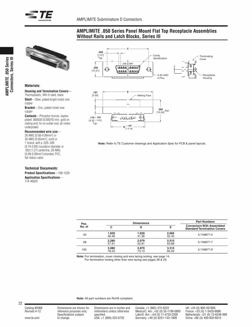
AMPLIMITE .050 Series Panel Mount Flat Top Receptacle AssembliesWithout Rails and Latch Blocks, Series III
AMPL
IMITE.0
50Se
ries
Conn
ectors,S
eriesIII
Materials:Housing and Termination Covers—Thermoplastic, 94V-0 rated, blackShell—Steel, plated bright nickel overcopperBracket—Zinc, plated nickel overcopperContacts—Phosphor bronze, duplexplated .000030 [0.00076] min. gold onmating end; tin on solder end; all nickelunderplatedRecommended wire size—28 AWG [0.08-0.09mm2] or30 AWG [0.05mm2], solid or7 strand, with a .029-.036[0.74-0.89] insulation diameter or.050 [1.27] centerline, 28 AWG[0.08-0.09mm2] stranded, PVC,flat ribbon cable
Technical Documents:Product Specifications—108-1228Application Specifications—114-40029
Dimensions Part NumbersPos.
C D E ConnectorsWith AssembledNo. ofStandard Termination Covers
1.830 1.629 2.06550 46.48 41.38 52.45 5-749877-5
2.280 2.079 2.51568 57.91 52.81 63.88 5-749877-7
3.080 2.879 3.315100 78.23 73.13 84.20 5-749877-9
Note: For termination, cover closing and wire lacing tooling, see page 14.Note: For termination tooling other than wire lacing see pages 28 & 29.
Note: Refer to TE Customer drawings and Application Spec for PCB & panel layouts.
C
EMating Face
TerminatingCover
ReceptacleHousing
4-40 UNC2 Plcs.
CavityIdentification
D ± .007[± 0.18]
.592[15.04]
.197[5.00]
.406[10.31]
.050[1.27]Typ.
.170 ± .002
[4.32 ± 0.05]Typ.
Ref.
23Catalog 82068 Dimensions are shown for Dimensions are in inches and Canada: +1 (905) 475-6222 UK: +44 (0) 800-267666Revised 4-12 reference purposes only. millimeters unless otherwise Mexico/C. Am.: +52 (0) 55-1106-0800 France: +33 (0) 1-3420-8686
Specifications subject specified. Latin/S. Am.: +54 (0) 11-4733-2200 Netherlands: +31 (0) 73-6246-999www.te.com to change. USA: +1 (800) 522-6752 Germany: +49 (0) 6251-133-1999 China: +86 (0) 400-820-6015
AMPLIMITE Subminiature D Connectors
Note: All part numbers are RoHS compliant.
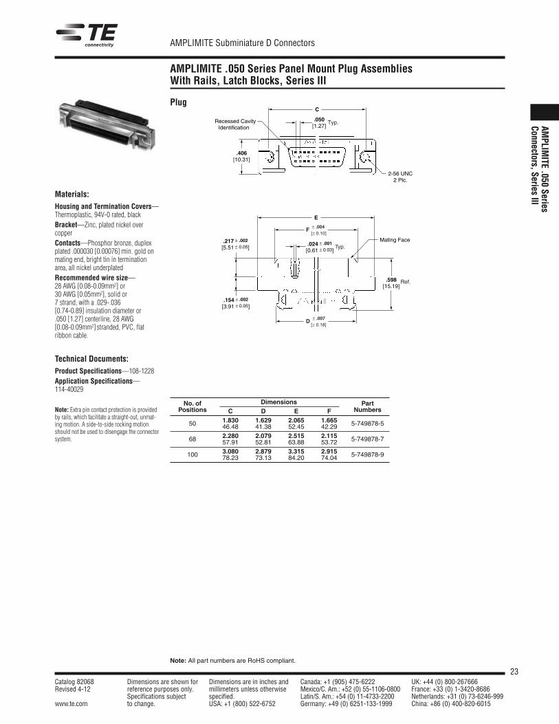
AMPLIMITE .050 Series Panel Mount Plug AssembliesWith Rails, Latch Blocks, Series III
AMPLIM
ITE.050
SeriesConnectors,Series
IIIMaterials:Housing and Termination Covers—Thermoplastic, 94V-0 rated, blackBracket—Zinc, plated nickel overcopperContacts—Phosphor bronze, duplexplated .000030 [0.00076] min. gold onmating end, bright tin in terminationarea, all nickel underplatedRecommended wire size—28 AWG [0.08-0.09mm2] or30 AWG [0.05mm2], solid or7 strand, with a .029-.036[0.74-0.89] insulation diameter or.050 [1.27] centerline, 28 AWG[0.08-0.09mm2] stranded, PVC, flatribbon cable.
Technical Documents:Product Specifications—108-1228Application Specifications—114-40029
Note: Extra pin contact protection is providedby rails, which facilitate a straight-out, unmat-ing motion. A side-to-side rocking motionshould not be used to disengage the connectorsystem.
Plug
2-56 UNC 2 Plc.
Recessed CavityIdentification
C
.050[1.27]
.406[10.31]
Typ.
Mating Face
E
.598 [15.19]
.024 ± .001
[0.61 ± 0.03]
F ± .004[± 0.10]
Typ.
D ± .007[± 0.18]
.217 ± .002
[5.51 ± 0.05]
.154 ± .002
[3.91 ± 0.05]
Ref.
No. of Dimensions PartPositions C D E F Numbers
50 1.830 1.629 2.065 1.665 5-749878-546.48 41.38 52.45 42.29
68 2.280 2.079 2.515 2.115 5-749878-757.91 52.81 63.88 53.72
100 3.080 2.879 3.315 2.915 5-749878-978.23 73.13 84.20 74.04
24Catalog 82068 Dimensions are shown for Dimensions are in inches and Canada: +1 (905) 475-6222 UK: +44 (0) 800-267666Revised 4-12 reference purposes only. millimeters unless otherwise Mexico/C. Am.: +52 (0) 55-1106-0800 France: +33 (0) 1-3420-8686
Specifications subject specified. Latin/S. Am.: +54 (0) 11-4733-2200 Netherlands: +31 (0) 73-6246-999www.te.com to change. USA: +1 (800) 522-6752 Germany: +49 (0) 6251-133-1999 China: +86 (0) 400-820-6015
AMPLIMITE Subminiature D Connectors
Note: All part numbers are RoHS compliant.
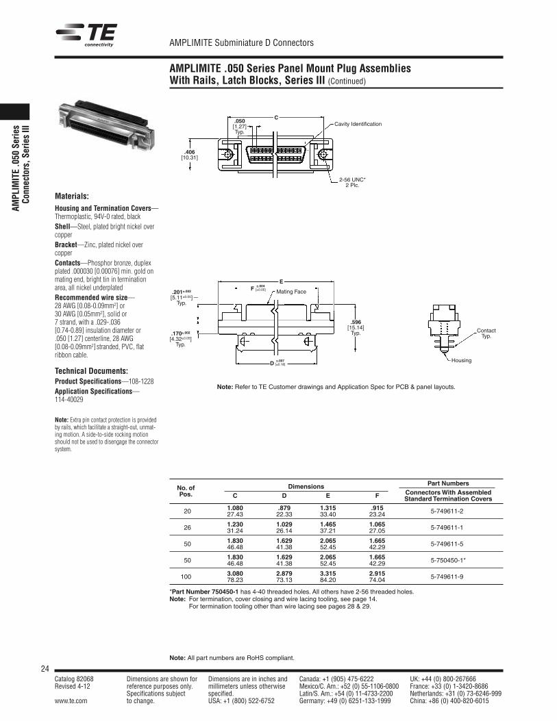
AMPLIMITE .050 Series Panel Mount Plug AssembliesWith Rails, Latch Blocks, Series III (Continued)
AMPL
IMITE.0
50Se
ries
Conn
ectors,S
eriesIII
Materials:Housing and Termination Covers—Thermoplastic, 94V-0 rated, blackShell—Steel, plated bright nickel overcopperBracket—Zinc, plated nickel overcopperContacts—Phosphor bronze, duplexplated .000030 [0.00076] min. gold onmating end, bright tin in terminationarea, all nickel underplatedRecommended wire size—28 AWG [0.08-0.09mm2] or30 AWG [0.05mm2], solid or7 strand, with a .029-.036[0.74-0.89] insulation diameter or.050 [1.27] centerline, 28 AWG[0.08-0.09mm2] stranded, PVC, flatribbon cable.
Technical Documents:Product Specifications—108-1228Application Specifications—114-40029
Note: Extra pin contact protection is providedby rails, which facilitate a straight-out, unmat-ing motion. A side-to-side rocking motionshould not be used to disengage the connectorsystem.
.201±.002[5.11±0.05]Typ.
E
C
±.004F [±0.05]
±.007D [±0.18]
.170±.002[4.32±0.05]Typ.
.596[15.14]Typ.
.050[1.27]Typ.
.406[10.31]
Mating Face
ContactTyp.
Housing
Cavity Identification
2-56 UNC*2 Plc.
Dimensions Part NumbersNo. of
C D E F ConnectorsWith AssembledPos.Standard Termination Covers
1.080 .879 1.315 .91520 27.43 22.33 33.40 23.24 5-749611-2*
1.230 1.029 1.465 1.06526 31.24 26.14 37.21 27.05 5-749611-1*
1.830 1.629 2.065 1.66550 46.48 41.38 52.45 42.29 5-749611-5*
1.830 1.629 2.065 1.66550 46.48 41.38 52.45 42.29 5-750450-1*
3.080 2.879 3.315 2.915100 78.23 73.13 84.20 74.04 5-749611-9*
*Part Number 750450-1 has 4-40 threaded holes. All others have 2-56 threaded holes.Note: For termination, cover closing and wire lacing tooling, see page 14.Note: For termination tooling other than wire lacing see pages 28 & 29.
Note: Refer to TE Customer drawings and Application Spec for PCB & panel layouts.
25Catalog 82068 Dimensions are shown for Dimensions are in inches and Canada: +1 (905) 475-6222 UK: +44 (0) 800-267666Revised 4-12 reference purposes only. millimeters unless otherwise Mexico/C. Am.: +52 (0) 55-1106-0800 France: +33 (0) 1-3420-8686
Specifications subject specified. Latin/S. Am.: +54 (0) 11-4733-2200 Netherlands: +31 (0) 73-6246-999www.te.com to change. USA: +1 (800) 522-6752 Germany: +49 (0) 6251-133-1999 China: +86 (0) 400-820-6015
AMPLIMITE Subminiature D Connectors
Note: All part numbers are RoHS compliant.
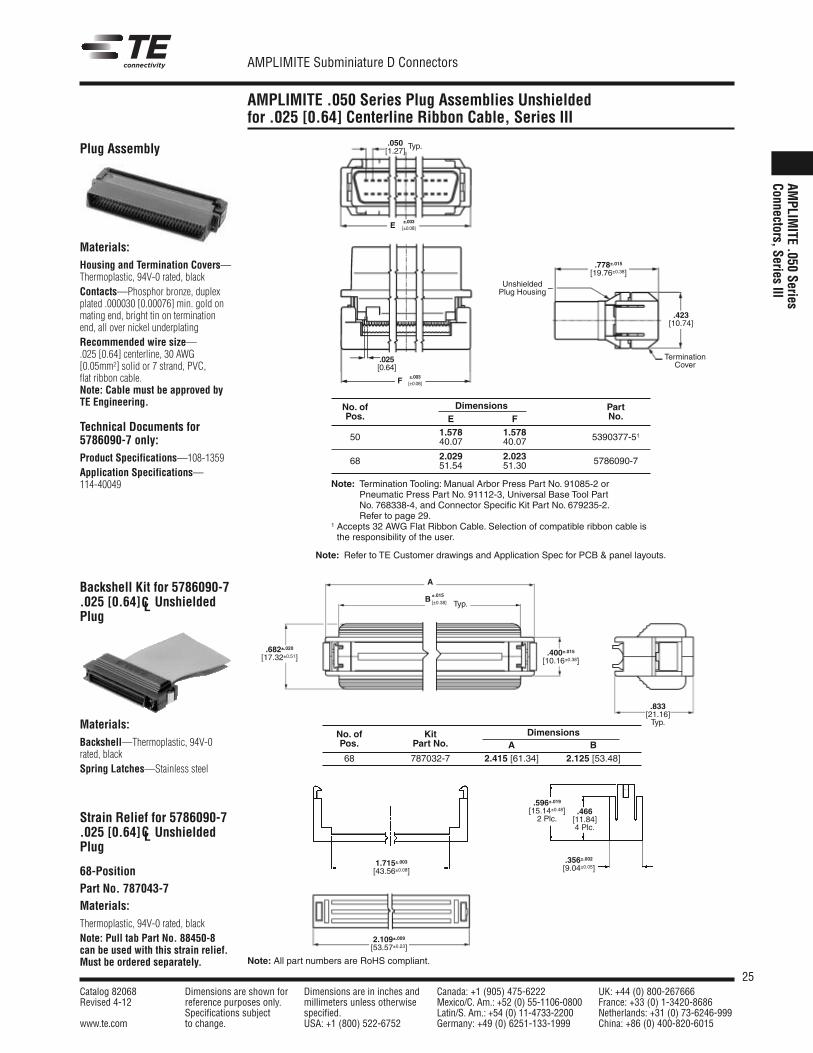
AMPLIMITE .050 Series Plug Assemblies Unshieldedfor .025 [0.64] Centerline Ribbon Cable, Series III
AMPLIM
ITE.050
SeriesConnectors,Series
III
Backshell Kit for 5786090-7.025 [0.64] C UnshieldedPlug
Materials:Housing and Termination Covers—Thermoplastic, 94V-0 rated, blackContacts—Phosphor bronze, duplexplated .000030 [0.00076] min. gold onmating end, bright tin on terminationend, all over nickel underplatingRecommended wire size—.025 [0.64] centerline, 30 AWG[0.05mm2] solid or 7 strand, PVC,flat ribbon cable.Note: Cable must be approved byTE Engineering.
Technical Documents for5786090-7 only:Product Specifications—108-1359Application Specifications—114-40049
No. of Dimensions PartPos. E F No.
1.578 1.57850 40.07 40.07 5390377-51
2.029 2.02368 51.54 51.30 5786090-7
±.003[±0.08]
.050[1.27]
Typ.
E
±.003[±0.08]F
.025[0.64]
UnshieldedPlug Housing
TerminationCover
.423[10.74]
.833[21.16]Typ.
.466[11.84]4 Plc.
B±.015
[±0.38]
A
Typ.
.682±.020[17.32±0.51]
.400±.015[10.16±0.38]
.596±.019[15.14±0.48]2 Plc.
.356±.002[9.04±0.05]
1.715±.003[43.56±0.08]
2.109±.009[53.57±0.23]
.778±.015[19.76±0.38]
Plug Assembly
Materials:Backshell—Thermoplastic, 94V-0rated, blackSpring Latches—Stainless steel
Strain Relief for 5786090-7.025 [0.64] C UnshieldedPlug
68-PositionPart No. 787043-7Materials:Thermoplastic, 94V-0 rated, blackNote: Pull tab Part No. 88450-8can be used with this strain relief.Must be ordered separately.
CL
CL
No. of Kit DimensionsPos. Part No. A B68 787032-7 2.415 [61.34] 2.125 [53.48]
Note: Termination Tooling: Manual Arbor Press Part No. 91085-2 orPneumatic Press Part No. 91112-3, Universal Base Tool PartNo. 768338-4, and Connector Specific Kit Part No. 679235-2.Refer to page 29.
1 Accepts 32 AWG Flat Ribbon Cable. Selection of compatible ribbon cable isthe responsibility of the user.
Note: Refer to TE Customer drawings and Application Spec for PCB & panel layouts.
26Catalog 82068 Dimensions are shown for Dimensions are in inches and Canada: +1 (905) 475-6222 UK: +44 (0) 800-267666Revised 4-12 reference purposes only. millimeters unless otherwise Mexico/C. Am.: +52 (0) 55-1106-0800 France: +33 (0) 1-3420-8686
Specifications subject specified. Latin/S. Am.: +54 (0) 11-4733-2200 Netherlands: +31 (0) 73-6246-999www.te.com to change. USA: +1 (800) 522-6752 Germany: +49 (0) 6251-133-1999 China: +86 (0) 400-820-6015
AMPLIMITE Subminiature D Connectors
Note: All part numbers are RoHS compliant.
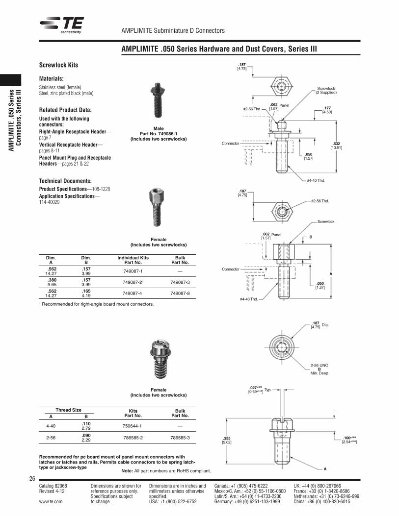
AMPLIMITE .050 Series Hardware and Dust Covers, Series III
AMPL
IMITE.0
50Se
ries
Conn
ectors,S
eriesIII
Materials:Stainless steel (female)Steel, zinc plated black (male)
Related Product Data:Used with the followingconnectors:Right-Angle Receptacle Header—page 7Vertical Receptacle Header—pages 8-11Panel Mount Plug and ReceptacleHeaders—pages 21 & 22
Technical Documents:Product Specifications—108-1228Application Specifications—114-40029
MalePart No. 749086-1
(Includes two screwlocks)
Female(Includes two screwlocks)
.187[4.75]
Screwlock(2 Supplied)
.177[4.50]
#4-40 Thd.
.532[13.51]
.050[1.27]
.062[1.57]#2-56 Thd.
B
A
#2-56 Thd.
.187[4.75]
#4-40 Thd.
Screwlock
Connector
Connector
Typ.
Dia..187[4.75]
.027±.003[0.69±0.08]
2-56 UNCB
Min. Deep
.100±.003[2.54±0.08]
.355[9.02]
A
Screwlock Kits
Dim. Dim. Individual Kits BulkA B Part No. Part No..562 .15714.27 3.99 749087-1 —
.380 .1579.65 3.99 749087-21 749087-3
.562 .16514.27 4.19 749087-4* 749087-8
1 Recommended for right-angle board mount connectors.
Female(Includes two screwlocks)
Recommended for pc board mount of panel mount connectors withlatches or latches and rails. Permits cable connectors to be spring latch-type or jackscrew-type
Panel
.062[1.57]
Panel
.050[1.27]
Thread Size Kits BulkA B Part No. Part No.
.1104-40 2.79 750644-1* —
.0902-56 2.29 786585-2 786585-3
27Catalog 82068 Dimensions are shown for Dimensions are in inches and Canada: +1 (905) 475-6222 UK: +44 (0) 800-267666Revised 4-12 reference purposes only. millimeters unless otherwise Mexico/C. Am.: +52 (0) 55-1106-0800 France: +33 (0) 1-3420-8686
Specifications subject specified. Latin/S. Am.: +54 (0) 11-4733-2200 Netherlands: +31 (0) 73-6246-999www.te.com to change. USA: +1 (800) 522-6752 Germany: +49 (0) 6251-133-1999 China: +86 (0) 400-820-6015
AMPLIMITE Subminiature D Connectors
AMPLIMITE .050 Series Performance Specifications andTechnical Documents
AMPLIM
ITE.050
SeriesConnectors,Series
III
Performance Specifications forRight-Angle, Vertical and .050Centerline Cable Products
Performance Specifications for.025 [1.27] Centerline RibbonCable Product. Same as aboveexcept:
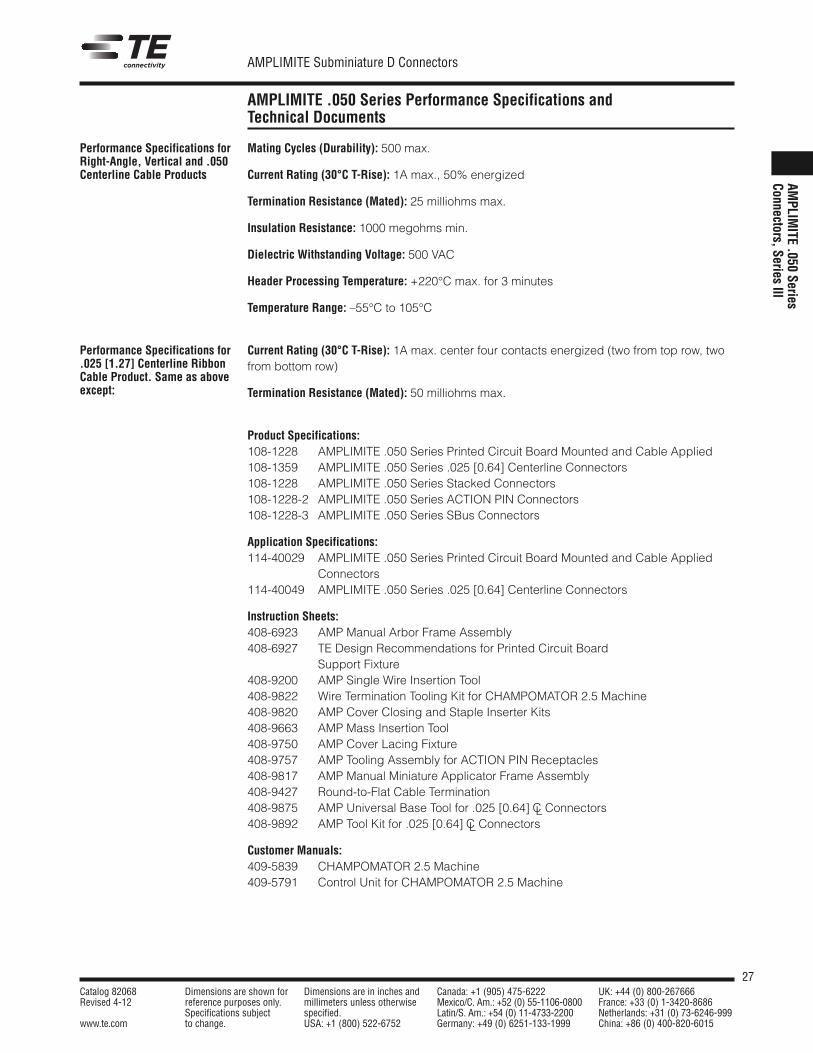
Mating Cycles (Durability): 500 max.
Current Rating (30°C T-Rise): 1A max., 50% energized
Termination Resistance (Mated): 25 milliohms max.
Insulation Resistance: 1000 megohms min.
Dielectric Withstanding Voltage: 500 VAC
Header Processing Temperature: +220°C max. for 3 minutes
Temperature Range: –55°C to 105°C
Current Rating (30°C T-Rise): 1A max. center four contacts energized (two from top row, twofrom bottom row)
Termination Resistance (Mated): 50 milliohms max.
Product Specifications:108-1228 AMPLIMITE .050 Series Printed Circuit Board Mounted and Cable Applied108-1359 AMPLIMITE .050 Series .025 [0.64] Centerline Connectors108-1228 AMPLIMITE .050 Series Stacked Connectors108-1228-2 AMPLIMITE .050 Series ACTION PIN Connectors108-1228-3 AMPLIMITE .050 Series SBus Connectors
Application Specifications:114-40029 AMPLIMITE .050 Series Printed Circuit Board Mounted and Cable Applied
Connectors114-40049 AMPLIMITE .050 Series .025 [0.64] Centerline Connectors
Instruction Sheets:408-6923 AMP Manual Arbor Frame Assembly408-6927 TE Design Recommendations for Printed Circuit Board
Support Fixture408-9200 AMP Single Wire Insertion Tool408-9822 Wire Termination Tooling Kit for CHAMPOMATOR 2.5 Machine408-9820 AMP Cover Closing and Staple Inserter Kits408-9663 AMP Mass Insertion Tool408-9750 AMP Cover Lacing Fixture408-9757 AMP Tooling Assembly for ACTION PIN Receptacles408-9817 AMP Manual Miniature Applicator Frame Assembly408-9427 Round-to-Flat Cable Termination408-9875 AMP Universal Base Tool for .025 [0.64] C Connectors408-9892 AMP Tool Kit for .025 [0.64] C Connectors
Customer Manuals:409-5839 CHAMPOMATOR 2.5 Machine409-5791 Control Unit for CHAMPOMATOR 2.5 Machine
CL
CL
28Catalog 82068 Dimensions are shown for Dimensions are in inches and Canada: +1 (905) 475-6222 UK: +44 (0) 800-267666Revised 4-12 reference purposes only. millimeters unless otherwise Mexico/C. Am.: +52 (0) 55-1106-0800 France: +33 (0) 1-3420-8686
Specifications subject specified. Latin/S. Am.: +54 (0) 11-4733-2200 Netherlands: +31 (0) 73-6246-999www.te.com to change. USA: +1 (800) 522-6752 Germany: +49 (0) 6251-133-1999 China: +86 (0) 400-820-6015
AMPLIMITE Subminiature D Connectors
Note: All part numbers are RoHS compliant.
AMPLIMITE .050 Series Application Tooling, Series III
AMPL
IMITE.0
50Se
ries
Conn
ectors,S
eriesIII
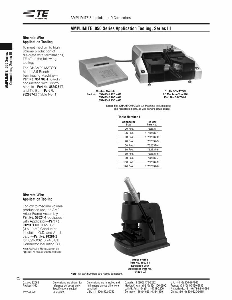
Discrete WireApplication ToolingTo meet medium to highvolume production ofdis-crete wire terminations,TE offers the followingtooling:
The CHAMPOMATORModel 2.5 BenchTerminating Machine—Part No. 354786-1, used inconjunction with ControlModule—Part No. 852423-,and Tie Bar—Part No.762637- (Table No. 1).
Discrete WireApplication Tooling
For low to medium volumeproduction use the AMPArbor Frame Assembly—Part No. 58024-1 equippedwith Applicator—Part No.91291-1 for .032-.035[0.81-0.89] ConductorInsulation O.D. and Appli-cator—Part No. 91291-2for .029-.032 [0.74-0.81]Conductor Insulation O.D.
Connector Tie BarSize Part No.
20 Pos. 1-762637-1
26 Pos. 1-762637-1
28 Pos. 1-762637-2
40 Pos. 1-762637-3
50 Pos. 1-762637-4
60 Pos. 1-762637-5
68 Pos. 1-762637-6
80 Pos. 1-762637-7
100 Pos. 1-762637-9
120 Pos. 1-762637-0
Note: The CHAMPOMATOR 2.5 Machine includes plugand receptacle nests, as well as wire setup gauge.
Control ModulePart No. 852423-1 120 VAC
852423-2 100 VAC852423-3 230 VAC
CHAMPOMATOR2.5 Machine Tool KitPart No. 354786-1
Table Number 1
Note: AMP Arbor Frame Assembly andApplicator Kit must be ordered separately.
Arbor FramePart No. 58024-1Equipped with
Applicator Part No.91291-
29Catalog 82068 Dimensions are shown for Dimensions are in inches and Canada: +1 (905) 475-6222 UK: +44 (0) 800-267666Revised 4-12 reference purposes only. millimeters unless otherwise Mexico/C. Am.: +52 (0) 55-1106-0800 France: +33 (0) 1-3420-8686
Specifications subject specified. Latin/S. Am.: +54 (0) 11-4733-2200 Netherlands: +31 (0) 73-6246-999www.te.com to change. USA: +1 (800) 522-6752 Germany: +49 (0) 6251-133-1999 China: +86 (0) 400-820-6015
AMPLIMITE Subminiature D Connectors
Note: All part numbers are RoHS compliant.
AMPLIMITE .050 Series Application Tooling, Series III (Continued)
AMPLIM
ITE.050
SeriesConnectors,Series
III
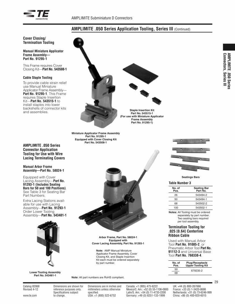
Cover Closing/Termination Tooling
Manual Miniature ApplicatorFrame Assembly—Part No. 91295-1
This Frame requires CoverClosing Kit—Part No. 543508-1
Cable Staple Tooling
To provide cable strain reliefuse Manual MiniatureApplicator Frame Assembly—Part No. 91295-1. This Framerequires Staple InsertionKit—Part No. 543515-1 toinstall staples into lowerbackshells of connector kitsand assemblies.
AMPLIMITE .050 SeriesConnector ApplicationTooling for Use with WireLacing Terminating Covers
Manual Arbor FrameAssembly—Part No. 58024-1
Equipped with CoverLacing Assembly—Part No.91293-1 (Includes SeatingBars for 50 and 100 Positions).See Table 3 for Seating BarPart Numbers.
Extra Lacing Stations avail-able for use with LacingAssembly—Part No. 91293-1Order Lower ToolingAssembly—Part No. 543481-1
Arbor Frame, Part No. 58024-1Equipped with
Cover Lacing Assembly, Part No. 91293-1
Seatings Bars
No. of Seating BarPos. Part No.
26 543494-2
50 543494-1
68 543502-2
100 543502-1
Notes: All Tooling must be orderedseparately by part number.Two seating bars requiredper tool assembly.
Table Number 3
Termination Tooling for.025 [0.64] CenterlineRibbon CableUsed with Manual ArborTool Part No. 91085-2, orPneumatic Arbor Tool Part No.91112-3 and Universal BaseTool Part No. 768338-4.
Staple Insertion KitPart No. 543515-1
(For use with Miniature ApplicatorFrame AssemblyPart No. 91295-1)
Miniature Applicator Frame AssemblyPart No. 91295-1
Equipped with Cover Closing KitPart No. 543508-1
Note: AMP Manual MiniatureApplicator Frame Assembly, CoverClosing Kit, and Staple InsertionKit each must be ordered separatelyby part number. No. of Plug/Receptacle
Pos. Upper Tooling Kit50 679235-268Lower Tooling Assembly
Part No. 543481-1
30Catalog 82068 Dimensions are shown for Dimensions are in inches and Canada: +1 (905) 475-6222 UK: +44 (0) 800-267666Revised 4-12 reference purposes only. millimeters unless otherwise Mexico/C. Am.: +52 (0) 55-1106-0800 France: +33 (0) 1-3420-8686
Specifications subject specified. Latin/S. Am.: +54 (0) 11-4733-2200 Netherlands: +31 (0) 73-6246-999www.te.com to change. USA: +1 (800) 522-6752 Germany: +49 (0) 6251-133-1999 China: +86 (0) 400-820-6015
AMPLIMITE Subminiature D Connectors
Shielded AMPLIMITE .050 Series Slimline Connectors
AMPL
IMITE.0
50Se
ries
Conn
ectors,S
eriesIII
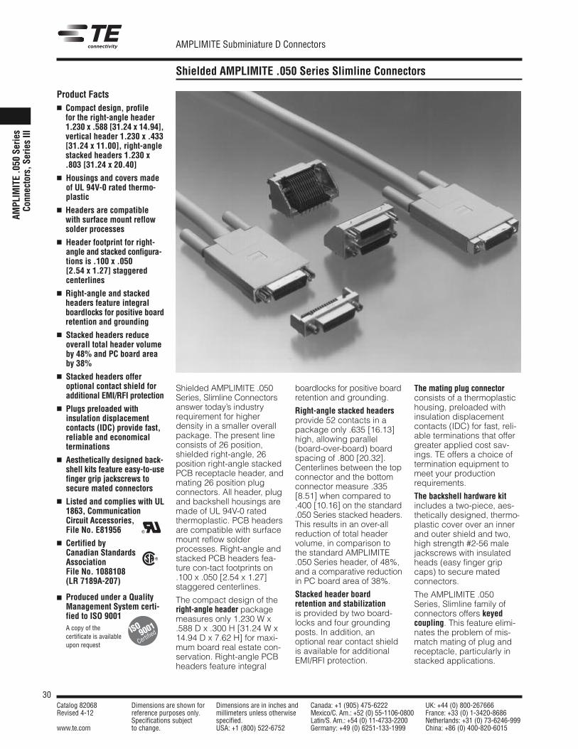
Product Facts Compact design, profile
for the right-angle header1.230 x .588 [31.24 x 14.94],vertical header 1.230 x .433[31.24 x 11.00], right-anglestacked headers 1.230 x.803 [31.24 x 20.40]
Housings and covers madeof UL 94V-0 rated thermo-plastic
Headers are compatiblewith surface mount reflowsolder processes
Header footprint for right-angle and stacked configura-tions is .100 x .050[2.54 x 1.27] staggeredcenterlines
Right-angle and stackedheaders feature integralboardlocks for positive boardretention and grounding
Stacked headers reduceoverall total header volumeby 48% and PC board areaby 38%
Stacked headers offeroptional contact shield foradditional EMI/RFI protection
Plugs preloaded with insulation displacementcontacts (IDC) provide fast,reliable and economical terminations
Aesthetically designed back-shell kits feature easy-to-usefinger grip jackscrews tosecure mated connectors
Listed and complies with UL1863, CommunicationCircuit Accessories,File No. E81956
Certified byCanadian StandardsAssociationFile No. 1088108 (LR 7189A-207)
Produced under a QualityManagement System certi-fied to ISO 9001
A copy of the certificate is available upon request
R
R
ISO
Certified9001
Shielded AMPLIMITE .050Series, Slimline Connectorsanswer today’s industryrequirement for higher density in a smaller overallpackage. The present lineconsists of 26 position,shielded right-angle, 26position right-angle stackedPCB receptacle header, andmating 26 position plugconnectors. All header, plugand backshell housings aremade of UL 94V-0 ratedthermoplastic. PCB headersare compatible with surfacemount reflow solderprocesses. Right-angle andstacked PCB headers fea-ture con-tact footprints on.100 x .050 [2.54 x 1.27]staggered centerlines.
The compact design of theright-angle header packagemeasures only 1.230 W x.588 D x .300 H [31.24 W x14.94 D x 7.62 H] for maxi-mum board real estate con-servation. Right-angle PCBheaders feature integral
boardlocks for positive boardretention and grounding.
Right-angle stacked headersprovide 52 contacts in apackage only .635 [16.13]high, allowing parallel(board-over-board) boardspacing of .800 [20.32].Centerlines between the topconnector and the bottomconnector measure .335[8.51] when compared to.400 [10.16] on the standard.050 Series stacked headers.This results in an over-allreduction of total headervolume, in comparison tothe standard AMPLIMITE.050 Series header, of 48%,and a comparative reductionin PC board area of 38%.
Stacked header boardretention and stabilizationis provided by two board-locks and four groundingposts. In addition, anoptional rear contact shieldis available for additionalEMI/RFI protection.
The mating plug connectorconsists of a thermoplastichousing, preloaded withinsulation displacementcontacts (IDC) for fast, reli-able terminations that offergreater applied cost sav-ings. TE offers a choice oftermination equipment tomeet your productionrequirements.
The backshell hardware kitincludes a two-piece, aes-thetically designed, thermo-plastic cover over an innerand outer shield and two,high strength #2-56 malejackscrews with insulatedheads (easy finger gripcaps) to secure mated connectors.
The AMPLIMITE .050Series, Slimline family ofconnectors offers keyedcoupling. This feature elimi-nates the problem of mis-match mating of plug andreceptacle, particularly instacked applications.
31Catalog 82068 Dimensions are shown for Dimensions are in inches and Canada: +1 (905) 475-6222 UK: +44 (0) 800-267666Revised 4-12 reference purposes only. millimeters unless otherwise Mexico/C. Am.: +52 (0) 55-1106-0800 France: +33 (0) 1-3420-8686
Specifications subject specified. Latin/S. Am.: +54 (0) 11-4733-2200 Netherlands: +31 (0) 73-6246-999www.te.com to change. USA: +1 (800) 522-6752 Germany: +49 (0) 6251-133-1999 China: +86 (0) 400-820-6015
AMPLIMITE Subminiature D Connectors
Note: All part numbers are RoHS compliant.
Shielded AMPLIMITE .050 Series Slimline Connectors (Continued)
AMPLIM
ITE .050 SeriesConnectors, Series III
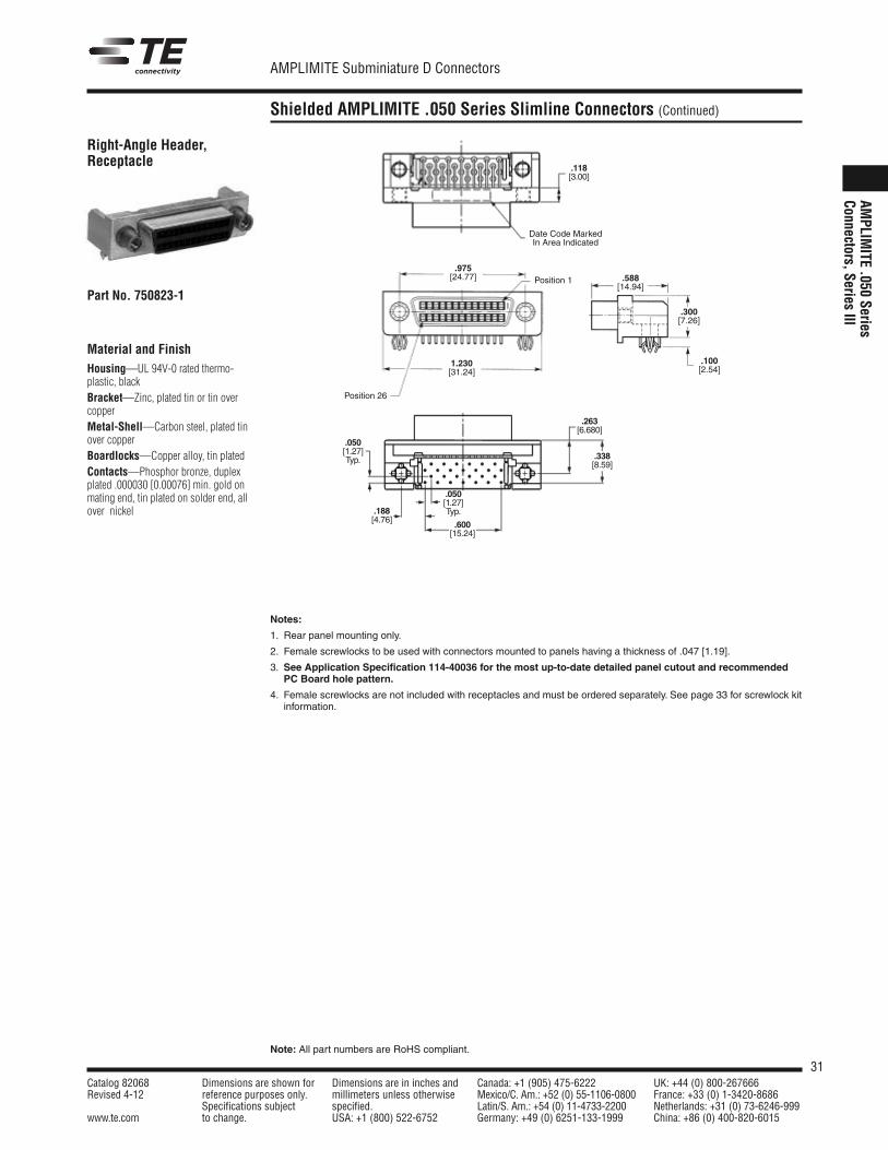
Material and FinishHousing—UL 94V-0 rated thermo-plastic, blackBracket—Zinc, plated tin or tin overcopperMetal-Shell—Carbon steel, plated tinover copperBoardlocks—Copper alloy, tin platedContacts—Phosphor bronze, duplexplated .000030 [0.00076] min. gold onmating end, tin plated on solder end, allover nickel
.975[24.77] .588
[14.94]
.300[7.26]
.100[2.54]
1.230[31.24]
Position 1
Position 26
Right-Angle Header,Receptacle
Part No. 750823-1
Notes:
1. Rear panel mounting only.
2. Female screwlocks to be used with connectors mounted to panels having a thickness of .047 [1.19].
3. See Application Specification 114-40036 for the most up-to-date detailed panel cutout and recommendedPC Board hole pattern.
4. Female screwlocks are not included with receptacles and must be ordered separately. See page 33 for screwlock kitinformation.
.118[3.00]
Date Code MarkedIn Area Indicated
.263[6.680]
.338[8.59]
.188[4.76]
.050[1.27]Typ.
.600[15.24]
.050[1.27]Typ.
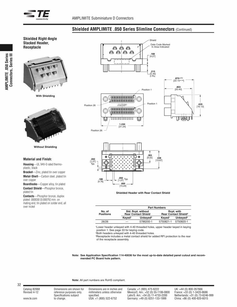
32Catalog 82068 Dimensions are shown for Dimensions are in inches and Canada: +1 (905) 475-6222 UK: +44 (0) 800-267666Revised 4-12 reference purposes only. millimeters unless otherwise Mexico/C. Am.: +52 (0) 55-1106-0800 France: +33 (0) 1-3420-8686
Specifications subject specified. Latin/S. Am.: +54 (0) 11-4733-2200 Netherlands: +31 (0) 73-6246-999www.te.com to change. USA: +1 (800) 522-6752 Germany: +49 (0) 6251-133-1999 China: +86 (0) 400-820-6015
AMPLIMITE Subminiature D Connectors
Note: All part numbers are RoHS compliant.
Shielded AMPLIMITE .050 Series Slimline Connectors (Continued)
AMPL
IMITE .0
50 Ser
ies
Conn
ectors, S
eries III
Material and Finish:Housing—UL 94V-0 rated thermo-plastic, blackBracket—Zinc, plated tin over copperMetal-Shell—Carbon steel, plated tinover copperBoardlocks—Copper alloy, tin platedContact Shield—Phosphor bronze,plated tinContacts—Phosphor bronze, duplexplated .000030 [0.00076] min. onmating end, tin plated on solder end, allover nickel
Shielded Right-AngleStacked Header,Receptacle
1.230[31.24]
.870±.015[22.10±0.38]
.803[20.40]
.635[16.13]
Position 1
Position 1Position 26
Position 26
Shielded Header with Rear Contact Shield
Part NumbersNo. of Std. Rcpt. without Rcpt. withPositions Rear Contact Shield Rear Contact Shield3
Keyed1 Unkeyed2 Keyed1 Unkeyed2
26/26 — 5786200-1 5750821-1 5750820-1
1Lower header unkeyed with 4-40 threaded holes, upper header keyed in keyingposition 1. See page 33 for keying code.2Both headers unkeyed with 4-40 threaded holes.3Receptacle includes a metal contact shield for added RFI protection to the rearof the receptacle assembly.
Shield
Date Code MarkedIn Area Indicated
.050[1.27]Typ.
.188[4.76]
.538[13.67]
.363[9.22]
.215[5.46]2 Plc.
.168[4.27]
.600[15.24]
.050[1.27] Typ.
Note: See Application Specification 114-40036 for the most up-to-date detailed panel cutout and recom-mended PC Board hole pattern.
With Shielding
Without Shielding
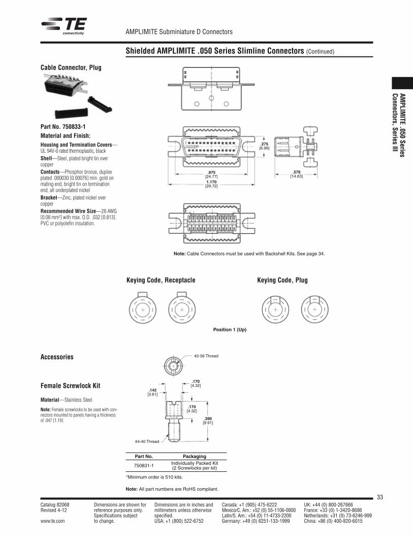
33Catalog 82068 Dimensions are shown for Dimensions are in inches and Canada: +1 (905) 475-6222 UK: +44 (0) 800-267666Revised 4-12 reference purposes only. millimeters unless otherwise Mexico/C. Am.: +52 (0) 55-1106-0800 France: +33 (0) 1-3420-8686
Specifications subject specified. Latin/S. Am.: +54 (0) 11-4733-2200 Netherlands: +31 (0) 73-6246-999www.te.com to change. USA: +1 (800) 522-6752 Germany: +49 (0) 6251-133-1999 China: +86 (0) 400-820-6015
AMPLIMITE Subminiature D Connectors
Note: All part numbers are RoHS compliant.
Shielded AMPLIMITE .050 Series Slimline Connectors (Continued)
AMPLIM
ITE .050 SeriesConnectors, Series III
Material and Finish:Housing and Termination Covers—UL 94V-0 rated thermoplastic, blackShell—Steel, plated bright tin overcopperContacts—Phosphor bronze, duplexplated .000030 [0.00076] min. gold onmating end, bright tin on terminationend, all underplated nickelBracket—Zinc, plated nickel over copperRecommended Wire Size—28 AWG[0.08 mm2] with max. O.D. .032 [0.813].PVC or polyolefin insulation.
Cable Connector, Plug
Part No. 750833-1
Note: Cable Connectors must be used with Backshell Kits. See page 34.
.275[6.99]
.975[24.77]1.170[29.72]
.576[14.63]
Keying Code, Receptacle Keying Code, Plug
Accessories
Female Screwlock Kit
Material—Stainless Steel
Note: Female screwlocks to be used with con-nectors mounted to panels having a thicknessof .047 [1.19]
Position 1 (Up)
#2-56 Thread
#4-40 Thread
.142[3.61]
.170[4.32]
.170[4.32]
.390[9.91]
Part No. PackagingIndividually Packed Kit750831-1 (2 Screwlocks per kit)
*Minimum order is 510 kits.
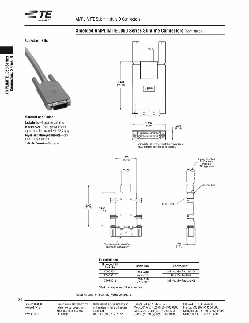
34Catalog 82068 Dimensions are shown for Dimensions are in inches and Canada: +1 (905) 475-6222 UK: +44 (0) 800-267666Revised 4-12 reference purposes only. millimeters unless otherwise Mexico/C. Am.: +52 (0) 55-1106-0800 France: +33 (0) 1-3420-8686
Specifications subject specified. Latin/S. Am.: +54 (0) 11-4733-2200 Netherlands: +31 (0) 73-6246-999www.te.com to change. USA: +1 (800) 522-6752 Germany: +49 (0) 6251-133-1999 China: +86 (0) 400-820-6015
AMPLIMITE Subminiature D Connectors
Note: All part numbers are RoHS compliant.
Shielded AMPLIMITE .050 Series Slimline Connectors (Continued)
AMPL
IMITE .0
50 Ser
ies
Conn
ectors, S
eries III
Backshell Kits
Material and Finish:Backshells—Copper-nickel alloyJackscrews—Steel, plated tin overcopper, handles covered with ABS, grayKeyed and Unkeyed Inserts—Zinc,plated tin over copperOutside Covers—ABS, gray Connector shown for illustration purposes
only, must be purchased separately.
1.745[44.32]
1.250[31.75] .330
[8.38]
Backshell KitsUnkeyed KitPart No. Cable Dia. Packaging*
750850-1 .250-.280 Individually Packed Kit750850-2 6.35-7.11 Bulk Packed Kit
750850-3 .280-.310 Individually Packed Kit7.11-7.87
*Bulk packaging—100 kits per box.
.805[20.45]
1.531[38.89] 1.252
[31.80]
Plug Assembly Must BePurchased Separately
.275[6.98]
Outer Shell
Inner Shell
Cable SuppliedBy CustomerMust Be
TE Approved
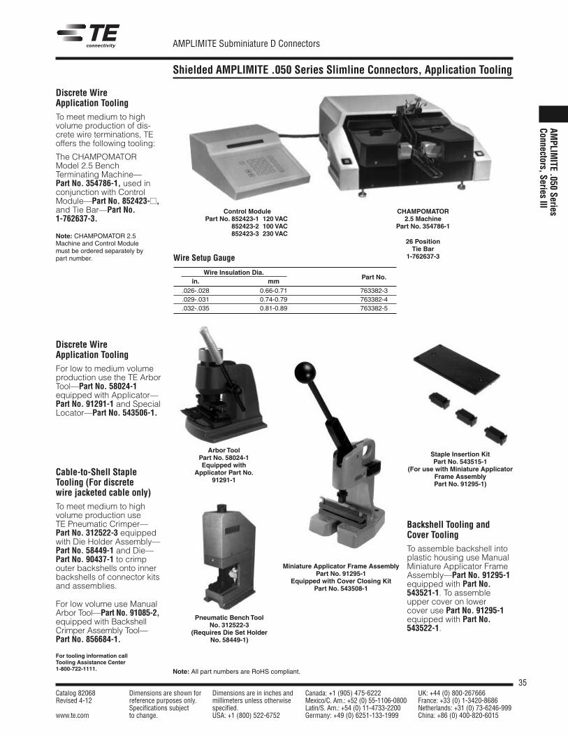
35Catalog 82068 Dimensions are shown for Dimensions are in inches and Canada: +1 (905) 475-6222 UK: +44 (0) 800-267666Revised 4-12 reference purposes only. millimeters unless otherwise Mexico/C. Am.: +52 (0) 55-1106-0800 France: +33 (0) 1-3420-8686
Specifications subject specified. Latin/S. Am.: +54 (0) 11-4733-2200 Netherlands: +31 (0) 73-6246-999www.te.com to change. USA: +1 (800) 522-6752 Germany: +49 (0) 6251-133-1999 China: +86 (0) 400-820-6015
AMPLIMITE Subminiature D Connectors
Note: All part numbers are RoHS compliant.
Shielded AMPLIMITE .050 Series Slimline Connectors, Application Tooling
AMPLIM
ITE .050 SeriesConnectors, Series III
Discrete WireApplication ToolingTo meet medium to high volume production of dis-crete wire terminations, TEoffers the following tooling:
The CHAMPOMATORModel 2.5 BenchTerminating Machine—Part No. 354786-1, used inconjunction with ControlModule—Part No. 852423-,and Tie Bar—Part No.1-762637-3.
Note: CHAMPOMATOR 2.5Machine and Control Modulemust be ordered separately bypart number.
Discrete WireApplication ToolingFor low to medium volumeproduction use the TE ArborTool—Part No. 58024-1equipped with Applicator—Part No. 91291-1 and SpecialLocator—Part No. 543506-1.
Backshell Tooling andCover ToolingTo assemble backshell intoplastic housing use ManualMiniature Applicator FrameAssembly—Part No. 91295-1equipped with Part No.543521-1. To assembleupper cover on lowercover use Part No. 91295-1equipped with Part No.543522-1.
Cable-to-Shell StapleTooling (For discretewire jacketed cable only)To meet medium to high volume production useTE Pneumatic Crimper—Part No. 312522-3 equippedwith Die Holder Assembly—Part No. 58449-1 and Die—Part No. 90437-1 to crimpouter backshells onto innerbackshells of connector kitsand assemblies.
For low volume use ManualArbor Tool—Part No. 91085-2,equipped with BackshellCrimper Assembly Tool—Part No. 856684-1.
Control ModulePart No. 852423-1 120 VAC
852423-2 100 VAC852423-3 230 VAC
For tooling information callTooling Assistance Center1-800-722-1111.
Pneumatic Bench ToolNo. 312522-3
(Requires Die Set HolderNo. 58449-1)
Staple Insertion KitPart No. 543515-1
(For use with Miniature ApplicatorFrame AssemblyPart No. 91295-1)
Miniature Applicator Frame AssemblyPart No. 91295-1
Equipped with Cover Closing KitPart No. 543508-1
CHAMPOMATOR2.5 Machine
Part No. 354786-1
26 PositionTie Bar
1-762637-3Wire Setup Gauge
Wire Insulation Dia.in. mm
Part No.
.026-.028 0.66-0.71 763382-3
.029-.031 0.74-0.79 763382-4
.032-.035 0.81-0.89 763382-5
Arbor ToolPart No. 58024-1Equipped with
Applicator Part No.91291-1
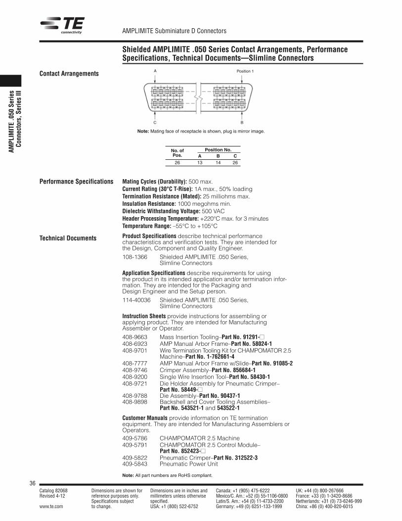
36Catalog 82068 Dimensions are shown for Dimensions are in inches and Canada: +1 (905) 475-6222 UK: +44 (0) 800-267666Revised 4-12 reference purposes only. millimeters unless otherwise Mexico/C. Am.: +52 (0) 55-1106-0800 France: +33 (0) 1-3420-8686
Specifications subject specified. Latin/S. Am.: +54 (0) 11-4733-2200 Netherlands: +31 (0) 73-6246-999www.te.com to change. USA: +1 (800) 522-6752 Germany: +49 (0) 6251-133-1999 China: +86 (0) 400-820-6015
AMPLIMITE Subminiature D Connectors
Note: All part numbers are RoHS compliant.
Shielded AMPLIMITE .050 Series Contact Arrangements, Performance Specifications, Technical Documents—Slimline Connectors
AMPL
IMITE .0
50 Ser
ies
Conn
ectors, S
eries III
Contact Arrangements
Performance Specifications
Technical Documents
Position 1A
BC
Note: Mating face of receptacle is shown, plug is mirror image.
No. of Position No.Pos. A B C26 13 14 26
Mating Cycles (Durability): 500 max.Current Rating (30°C T-Rise): 1A max., 50% loadingTermination Resistance (Mated): 25 milliohms max.Insulation Resistance: 1000 megohms min.Dielectric Withstanding Voltage: 500 VACHeader Processing Temperature: +220°C max. for 3 minutesTemperature Range: –55°C to +105°C
Product Specifications describe technical performancecharacteristics and verification tests. They are intended forthe Design, Component and Quality Engineer.108-1366 Shielded AMPLIMITE .050 Series,
Slimline Connectors
Application Specifications describe requirements for usingthe product in its intended application and/or termination infor-mation. They are intended for the Packaging andDesign Engineer and the Setup person.114-40036 Shielded AMPLIMITE .050 Series,
Slimline Connectors
Instruction Sheets provide instructions for assembling orapplying product. They are intended for ManufacturingAssembler or Operator.408-9663 Mass Insertion Tooling–Part No. 91291-408-6923 AMP Manual Arbor Frame–Part No. 58024-1408-9701 Wire Termination Tooling Kit for CHAMPOMATOR 2.5
Machine–Part No. 1-762661-4408-7777 AMP Manual Arbor Frame w/Slide–Part No. 91085-2408-9746 Crimper Assembly–Part No. 856684-1408-9200 Single Wire Insertion Tool–Part No. 58430-1408-9721 Die Holder Assembly for Pneumatic Crimper–
Part No. 58449-408-9788 Die Assembly–Part No. 90437-1408-9898 Backshell and Cover Tooling Assemblies–
Part No. 543521-1 and 543522-1
Customer Manuals provide information on TE termination equipment. They are intended for Manufacturing Assemblers orOperators.409-5786 CHAMPOMATOR 2.5 Machine409-5791 CHAMPOMATOR 2.5 Control Module–
Part No. 852423-409-5822 Pneumatic Crimper–Part No. 312522-3409-5843 Pneumatic Power Unit
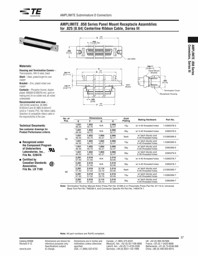
37Catalog 82068 Dimensions are shown for Dimensions are in inches and Canada: +1 (905) 475-6222 UK: +44 (0) 800-267666Revised 4-12 reference purposes only. millimeters unless otherwise Mexico/C. Am.: +52 (0) 55-1106-0800 France: +33 (0) 1-3420-8686
Specifications subject specified. Latin/S. Am.: +54 (0) 11-4733-2200 Netherlands: +31 (0) 73-6246-999www.te.com to change. USA: +1 (800) 522-6752 Germany: +49 (0) 6251-133-1999 China: +86 (0) 400-820-6015
AMPLIMITE Subminiature D Connectors
Note: All part numbers are RoHS compliant.
AMPLIMITE .050 Series Panel Mount Receptacle Assembliesfor .025 [0.64] Centerline Ribbon Cable, Series III
AMPLIM
ITE .050 SeriesConnectors, Series III
Materials:Housing and Termination Covers—Thermoplastic, 94V-0 rated, blackShell—Steel, plated bright tin overcopperBracket—Zinc, plated nickel overcopperContacts—Phosphor bronze, duplexplated .000030 [0.00076] min. gold onmating end; tin on solder end; all nickelunderplatedRecommended wire size—.025 [0.64] centerline, 30 AWG[0.05mm2] and 32 AWG [0.03mm2] solid or 7 strand, PVC, flat ribbon cable.Selection of compatible ribbon cable isthe responsibility of the user.
Technical Documents:See customer drawings forProduct Performance criteria.
Recognized underthe Component Programof UnderwritersLaboratories, Inc.,File No. E28476
Certified by Canadian StandardsAssociation,File No. LR 7189
R
R
Termination Cover
Receptacle Housing
Panel MountBracket
.423[10.74]
.786±.015[19.96±0.38]
±.006[±0.15]
.406[10.31]
E
±.003[±0.08]F
.025[0.64]
.050[1.27]Typ.
see table
H
.201±.002[5.11±0.05]
.170±.002[4.32±0.05]
G±.004[±0.10]
latchblocks
No. of Dimensions Gold Mating Hardware Part No.Pos. E F G H Plating
1.831 1.602 2.066 w/ 4-40 threaded holes46.50 40.70 N/A 52.47 15µ 1-5390378-5
1.831 1.602 2.066 w/ 4-40 threaded holes46.50 40.70 N/A 52.47 30µ 5390378-5
1.831 1.602 1.664 2.066 w/ latch blocks and
50 46.50 40.70 42.27 52.47 flash 4-40 threaded holes 2-5390399-5
1.831 1.602 1.664 2.066 w/ latch blocks and46.50 40.70 42.27 52.47 15µ 4-40 threaded holes 1-5390399-5
1.831 1.602 1.664 2.066 w/ latch blocks and46.50 40.70 42.27 52.47 30µ 4-40 threaded holes 5390399-5
1.831 1.602 1.664 2.066 w/ latch blocks and46.50 40.70 42.27 52.47 30µ 2-56 threaded holes 5390379-5
2.281 2.018 2.516 w/ 4-40 threaded holes57.93 51.50 N/A 63.90 15µ 1-5390378-7
2.281 2.018 2.516 w/ 4-40 threaded holes57.93 51.50 N/A 63.90 30µ 5390378-7
2.281 2.018 2.114 2.516 w/ latch blocks and
68 57.93 51.50 53.70 63.90 flash 4-40 threaded holes 2-5390399-7
2.281 2.018 2.114 2.516 w/ latch blocks and57.93 51.50 53.70 63.90 15µ 4-40 threaded holes 1-5390399-7
2.281 2.018 2.114 2.516 w/ latch blocks and57.93 51.50 53.70 63.90 30µ 4-40 threaded holes 5390399-7
Note: Termination Tooling: Manual Arbor Press Part No. 91085-2 or Pneumatic Press Part No. 91112-3, UniversalBase Tool Part No. 768338-4, and Connector Specific Kit Part No. 1490479-1.
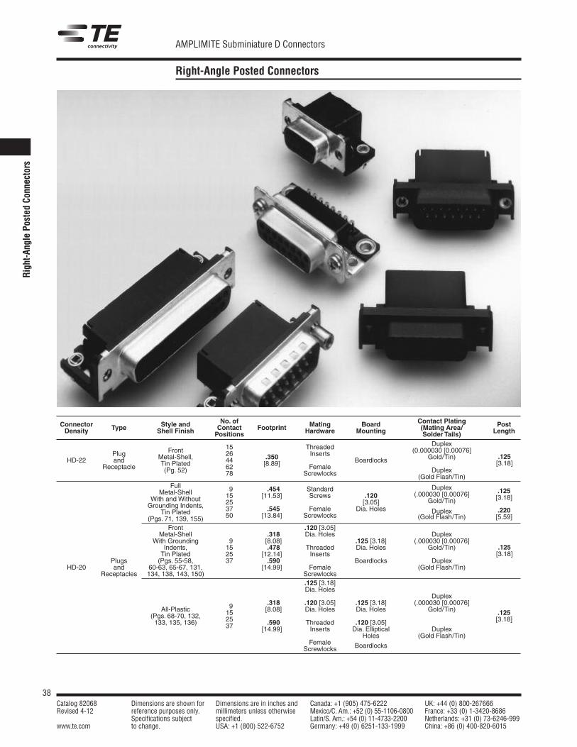
38Catalog 82068 Dimensions are shown for Dimensions are in inches and Canada: +1 (905) 475-6222 UK: +44 (0) 800-267666Revised 4-12 reference purposes only. millimeters unless otherwise Mexico/C. Am.: +52 (0) 55-1106-0800 France: +33 (0) 1-3420-8686
Specifications subject specified. Latin/S. Am.: +54 (0) 11-4733-2200 Netherlands: +31 (0) 73-6246-999www.te.com to change. USA: +1 (800) 522-6752 Germany: +49 (0) 6251-133-1999 China: +86 (0) 400-820-6015
AMPLIMITE Subminiature D Connectors
Right-AnglePo
sted
Connectors
Right-Angle Posted Connectors
No. of Contact PlatingConnector Type Style and Contact Footprint Mating Board (Mating Area/ PostDensity Shell Finish Positions Hardware Mounting Solder Tails) Length
Duplex
Plug Front 15 Threaded (0.000030 [0.00076]
HD-22 and Metal-Shell, 26 .350 InsertsBoardlocks Gold/Tin)
Receptacle Tin Plated 44 [8.89](Pg. 52) 62 Female Duplex78 Screwlocks (Gold Flash/Tin)Full 9 .454 Standard Duplex .125Metal-Shell 15 [11.53] Screws (.000030 [0.00076] [3.18]With and Without 25
.120Gold/Tin)
Grounding Indents, 37 .545 Female[3.05]
Tin Plated 50 [13.84] ScrewlocksDia. Holes Duplex .220
(Pgs. 71, 139, 155) (Gold Flash/Tin) [5.59]
Front .120 [3.05]Metal-Shell Dia. Holes Duplex
With Grounding.318
(.000030 [0.00076]Indents,
[8.08]Threaded Gold/Tin)
Tin Plated
9.478
Inserts
.125 [3.18]
Plugs (Pgs. 55-58,
15[12.14]
Dia. Holes
DuplexHD-20 and 60-63, 65-67, 131,
25.590
Female (Gold Flash/Tin)Receptacles 134, 138, 143, 150)
37[14.99]
Screwlocks
Boardlocks
.125 [3.18]Dia. Holes
Duplex.318 .120 [3.05] .125 [3.18] (.000030 [0.00076]
All-Plastic 9 [8.08] Dia. Holes Dia. Holes Gold/Tin) .125(Pgs. 68-70, 132, 15[3.18]133, 135, 136) 25 .590 Threaded .120 [3.05]37 [14.99] Inserts Dia. Elliptical Duplex
Holes (Gold Flash/Tin)Female
Screwlocks Boardlocks
.125[3.18]
.125[3.18]
39Catalog 82068 Dimensions are shown for Dimensions are in inches and Canada: +1 (905) 475-6222 UK: +44 (0) 800-267666Revised 4-12 reference purposes only. millimeters unless otherwise Mexico/C. Am.: +52 (0) 55-1106-0800 France: +33 (0) 1-3420-8686
Specifications subject specified. Latin/S. Am.: +54 (0) 11-4733-2200 Netherlands: +31 (0) 73-6246-999www.te.com to change. USA: +1 (800) 522-6752 Germany: +49 (0) 6251-133-1999 China: +86 (0) 400-820-6015
AMPLIMITE Subminiature D Connectors
Right-Angle Posted Connectors (Continued)
Product Facts: Flame retardant
thermoplastic housingmaterial, UL 94V-0 rated
HD-20 right-angleconnectors are available in9, 15, 25 and 37 positions(Shell Sizes 1 thru 4) inboth plug and receptacleversions; some versionsavailable in 50 position,(Shell Size 5)
HD-20 stacked connectorsare available in 9/9, 15/15,25/25, and 37/37 positions(Shell Sizes 1 thru 4) inreceptacle over receptacle,plug over plug andcombination versions
HD-22 right-anglereceptacle connectors areavailable in 15, 26, 44, 62and 78 positions (ShellSizes 1 thru 5)
Low cost front metal-shelldesign compatible with fullmetal-shell connectors
Integral boardlock versionssecure posted connectors topc boards prior to soldering
HD-20 and HD-22 connectorcontacts are available inplating types to satisfydifferent applications
HD-22 right-angle postedconnectors are designedfor high temperatureapplications
Integral fixed 4-40 threadedinserts and screwlocks areavailable in both HD-20 andHD-22 connectors
Connectors are intermate-able with any size 20 or 22subminiature D connectorsdimensionally complyingwith MIL-C-24308
Section ContentsHD-22 and HD-20 Contact Arrangements . . . . . . . . . . . . . . . . . . . . . . . . . . . . . . . . . . 40HD-22 and HD-20 Performance Specifications . . . . . . . . . . . . . . . . . . . . . . . . . . . . . 41Plug/Receptacle Mating and Panel Mounting Specifications . . . . . . . . . . . . . . . 42AMPLIMITE HD-20 Subminiature D Stacked PCB Connectors
Hybrid and Mixed Styles . . . . . . . . . . . . . . . . . . . . . . . . . . . . . . . . . . . . . . . . . . . . 43-48AMPLIMITE 2000 Subminiature D Connectors . . . . . . . . . . . . . . . . . . . . . . . . . . 49, 50HD-20 and HD-22 Slimline Connectors . . . . . . . . . . . . . . . . . . . . . . . . . . . . . . . . . . . . . 51HD-22 Right-Angle Posted Subminiature D Connectors . . . . . . . . . . . . . . . . 52, 53HD-20 Front Metal-Shell Right-Angle Posted Connectors
318 Mount . . . . . . . . . . . . . . . . . . . . . . . . . . . . . . . . . . . . . . . . . . . . . . . . . . . . . . . . . . . 54-57HD-20 Full Metal-Shell Right-Angle Posted Connectors
454 Mount . . . . . . . . . . . . . . . . . . . . . . . . . . . . . . . . . . . . . . . . . . . . . . . . . . . . . . . . . . 58, 59HD-20 Front Metal-Shell Right-Angle Posted Connectors
478 Mount . . . . . . . . . . . . . . . . . . . . . . . . . . . . . . . . . . . . . . . . . . . . . . . . . . . . . . . . . . 60, 61HD-20 Full Metal-Shell Right-Angle Posted Connectors
545 Mount . . . . . . . . . . . . . . . . . . . . . . . . . . . . . . . . . . . . . . . . . . . . . . . . . . . . . . . . . . 62, 63HD-20 Front Metal-Shell Right-Angle Posted Connectors
590 Mount . . . . . . . . . . . . . . . . . . . . . . . . . . . . . . . . . . . . . . . . . . . . . . . . . . . . . . . . . . 64, 65HD-20 All-Plastic Right-Angle Posted Connectors
318 Mount . . . . . . . . . . . . . . . . . . . . . . . . . . . . . . . . . . . . . . . . . . . . . . . . . . . . . . . . . . . 66-68HD-20 All-Plastic Right-Angle Posted Connectors
590 Mount . . . . . . . . . . . . . . . . . . . . . . . . . . . . . . . . . . . . . . . . . . . . . . . . . . . . . . . . . . . 69-71Right-Angle Mounting Connectors—European Standard Footprint . . . . . . . . . 72Right-Angle Mounting Connectors—Eurostyle Footprint . . . . . . . . . . . . . . . . . . . . 73Standard Density Press Fit Termination, Right-Angle Mounting . . . . . . . . . . . . . 74Subminiature D Connectors for Cable Mounting. . . . . . . . . . . . . . . . . . . . . . . . . . . . 75
No. of Contact PlatingConnector Type Style and Contact Footprint Mating Board (Mating Area/ PostDensity Shell Finish Positions Hardware Mounting Solder Tails) Length
Receptacleover
Receptacle
Plug Duplex
over Threaded (.000030 [0.00076]
Plug Front 9/9See Inserts .120 [3.05] Gold/Tin)
HD-20 Metal-Shell, 15/15Customer Dia. Holes (.000010 [0.00025] .125
Receptacle Tin Plated 25/25Drawings Female Gold/Tin) [3.18]
over (Pgs. 144-149, 151) 37/37Screwlocks Boardlocks
Plug(Std.) Duplex
(Gold Flash/Tin)
Plugover
Receptacle
Right-Angle Stacked Connectors (Centerline-to-centerline height .750 [19.05])
Right-Angle
PostedConnectors
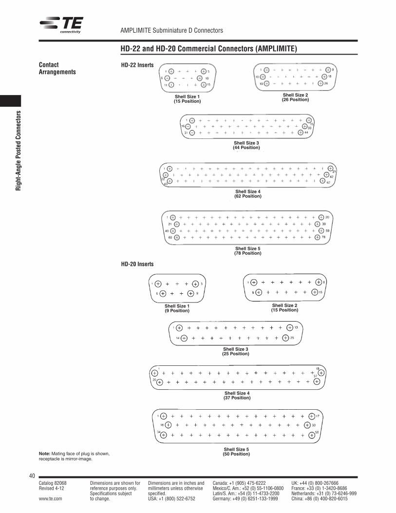
40Catalog 82068 Dimensions are shown for Dimensions are in inches and Canada: +1 (905) 475-6222 UK: +44 (0) 800-267666Revised 4-12 reference purposes only. millimeters unless otherwise Mexico/C. Am.: +52 (0) 55-1106-0800 France: +33 (0) 1-3420-8686
Specifications subject specified. Latin/S. Am.: +54 (0) 11-4733-2200 Netherlands: +31 (0) 73-6246-999www.te.com to change. USA: +1 (800) 522-6752 Germany: +49 (0) 6251-133-1999 China: +86 (0) 400-820-6015
AMPLIMITE Subminiature D Connectors
Right-AnglePo
sted
Connectors
HD-22 and HD-20 Commercial Connectors (AMPLIMITE)
ContactArrangements
Note:Mating face of plug is shown,receptacle is mirror-image.
HD-22 Inserts
HD-20 Inserts
Shell Size 5(50 Position)
Shell Size 1(15 Position)
Shell Size 1(9 Position)
Shell Size 2(15 Position)
Shell Size 4(37 Position)
Shell Size 2(26 Position)
Shell Size 3(44 Position)
Shell Size 4(62 Position)
Shell Size 5(78 Position)
Shell Size 3(25 Position)
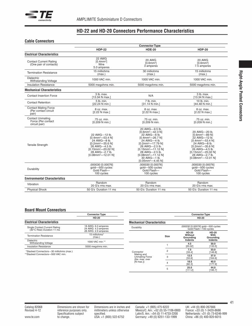
41Catalog 82068 Dimensions are shown for Dimensions are in inches and Canada: +1 (905) 475-6222 UK: +44 (0) 800-267666Revised 4-12 reference purposes only. millimeters unless otherwise Mexico/C. Am.: +52 (0) 55-1106-0800 France: +33 (0) 1-3420-8686
Specifications subject specified. Latin/S. Am.: +54 (0) 11-4733-2200 Netherlands: +31 (0) 73-6246-999www.te.com to change. USA: +1 (800) 522-6752 Germany: +49 (0) 6251-133-1999 China: +86 (0) 400-820-6015
AMPLIMITE Subminiature D Connectors
HD-22 and HD-20 Connectors Performance Characteristics
Connector TypeHD-20
Mechanical CharacteristicsDurability .000030 [0.00076] gold—500 cycles
Gold Flash—100 cycles
HD-20 HD-20Without WithGrounding GroundingSize
Indents Indents
4.5 30.01 [20.02] [133.5]7.5 33.02 [33.4] [146.8]12.5 37.03 [55.6] [164.6]18.5 40.04 [82.3] [177.9]25.0 44.05 [111.2] [195.7]
Cable ConnectorsConnector Type
HDP-22 HDE-20 HDP-20
Electrical Characteristics22 AWG 20 AWG 20 AWGContact Current Rating [0.4mm2] [0.6mm2] [0.6mm2](One pair of contacts) Wire 3 amperes 7.5 amperes5.0 amperes
15 milliohms 30 milliohms 15 milliohmsTermination Resistance (max.) (max.) (max.)DielectricWithstanding Voltage 1000 VAC min. 1000 VAC min. 1000 VAC min.
Insulation Resistance 5000 megohms min. 5000 megohms min. 5000 megohms min.
Mechanical Characteristics3 lb. max. 3 lb. max.Contact Insertion Force [13.34 N max.] N/A [13.34 N max.]5 lb. min. 7 lb. min. 10 lb. min.Contact Retention [22.24 N min.] [31.14 N min.] [44.48 N min.]
Contact Mating Force(Per contact circuit 8 oz. max. 8 oz. max. 8 oz. max.
pair) [2.22 N max.] [2.22 N max.] [2.22 N max.]
Contact UnmatingForce (Per contact
.75 oz. min. .75 oz. min. .75 oz. min.
circuit pair)[0.209 N min.] [0.209 N min. [0.209 N min.]
20 AWG—9.5 lb.[0.6mm2—42.3 N]22 AWG—6 lb.
20 AWG—20 lb.
[0.4mm2—26.7 N][0.6mm2—89 N]22 AWG—12 lb.
24 AWG—4 lb.22 AWG—12 lb.[0.4mm2—53.4 N]
[0.2mm2—17.79 N][0.4mm2—53.4 N]
Tensile Strength
24 AWG—8 lb.
26 AWG—2.5 lb.24 AWG—8 lb.[0.2mm2—35.6 N]
[0.15mm2—11.12 N][0.2mm2—35.6 N]26 AWG—4.5 lb.
28 AWG—2.5 lb.26 AWG—4.5 lb.[0.15mm2—20.02 N]
[0.08mm2—11.12 N][0.15mm2—20.02 N]28 AWG—2.7 lb.
30 AWG—1 lb.28 AWG—2.7 lb.[0.08mm2—12.01 N]
[0.05mm2—4.45 N][0.08mm2—12.01 N]
.000030 [0.00076] .000030 [0.00076] .000030 [0.00076]gold—500 cycles gold—500 cycles gold—500 cyclesGold Flash— Gold Flash— Gold Flash—Durability
100 cycles 100 cycles 100 cycles
Environmental CharacteristicsRandom Random RandomVibration 20 G’s rms max. 20 G’s rms max. 20 G’s rms max.
Physical Shock 50 G’s Duration 11 ms 50 G’s Duration 11 ms 50 G’s Duration 11 ms
Connector TypeHD-20
Electrical Characteristics
Single Contact Current Rating 18 AWG 6.0 amperes
(30°C Rise) Duration 11 ms 24 AWG 4.3 amperes28 AWG 2.9 amperes
15 milliohms*Termination Resistance (max.)DielectricWithstanding Voltage 1000 VAC min.**
Insulation Resistance 5000 megohms min.
ConnectorMating andUnmating Force(lbs. max. over[N max.])
**Stacked Connectors—30 milliohms (max.)**Stacked Connectors—500 VAC min.
Board Mount Connectors
Right-Angle
PostedConnectors
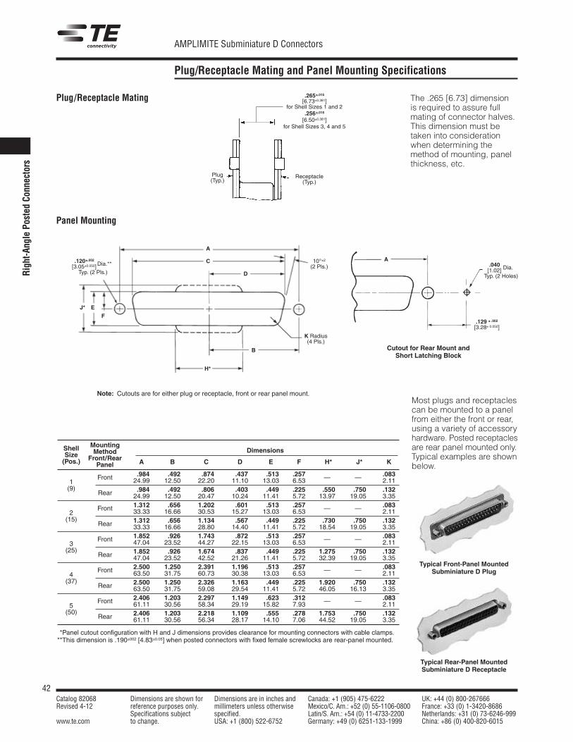
42Catalog 82068 Dimensions are shown for Dimensions are in inches and Canada: +1 (905) 475-6222 UK: +44 (0) 800-267666Revised 4-12 reference purposes only. millimeters unless otherwise Mexico/C. Am.: +52 (0) 55-1106-0800 France: +33 (0) 1-3420-8686
Specifications subject specified. Latin/S. Am.: +54 (0) 11-4733-2200 Netherlands: +31 (0) 73-6246-999www.te.com to change. USA: +1 (800) 522-6752 Germany: +49 (0) 6251-133-1999 China: +86 (0) 400-820-6015
AMPLIMITE Subminiature D Connectors
Plug/Receptacle Mating and Panel Mounting Specifications
Plug/Receptacle Mating
Panel Mounting
The .265 [6.73] dimensionis required to assure fullmating of connector halves.This dimension must betaken into considerationwhen determining themethod of mounting, panelthickness, etc.
Cutout for Rear Mount andShort Latching Block
Most plugs and receptaclescan be mounted to a panelfrom either the front or rear,using a variety of accessoryhardware. Posted receptaclesare rear panel mounted only.Typical examples are shownbelow.
Typical Front-Panel MountedSubminiature D Plug
Typical Rear-Panel MountedSubminiature D Receptacle
Shell Mounting
Size Method Dimensions
(Pos.) Front/Rear A B C D E F *H* *J* KPanel.984 .492 .874 .437 .513 .257 .083
1Front 24.99 12.50 22.20 11.10 13.03 6.53 — — 2.11
(9) .984 .492 .806 .403 .449 .225 .550 .750 .132Rear 24.99 12.50 20.47 10.24 11.41 5.72 13.97 19.05 3.351.312 .656 1.202 .601 .513 .257 .083
2Front 33.33 16.66 30.53 15.27 13.03 6.53 — — 2.11
(15) 1.312 .656 1.134 .567 .449 .225 .730 .750 .132Rear 33.33 16.66 28.80 14.40 11.41 5.72 18.54 19.05 3.351.852 .926 1.743 .872 .513 .257 .083
3Front 47.04 23.52 44.27 22.15 13.03 6.53 — — 2.11
(25) 1.852 .926 1.674 .837 .449 .225 1.275 .750 .132Rear 47.04 23.52 42.52 21.26 11.41 5.72 32.39 19.05 3.352.500 1.250 2.391 1.196 .513 .257 .083
4Front 63.50 31.75 60.73 30.38 13.03 6.53 — — 2.11
(37) 2.500 1.250 2.326 1.163 .449 .225 1.920 .750 .132Rear 63.50 31.75 59.08 29.54 11.41 5.72 46.05 16.13 3.352.406 1.203 2.297 1.149 .623 .312 .083
5Front 61.11 30.56 58.34 29.19 15.82 7.93 — — 2.11
(50) 2.406 1.203 2.218 1.109 .555 .278 1.753 .750 .132Rear 61.11 30.56 56.34 28.17 14.10 7.06 44.52 19.05 3.35
**Panel cutout configuration with H and J dimensions provides clearance for mounting connectors with cable clamps.**This dimension is .190±002 [4.83±0.05] when posted connectors with fixed female screwlocks are rear-panel mounted.
Note: Cutouts are for either plug or receptacle, front or rear panel mount.
.265±.015[6.73±0.381]
for Shell Sizes 1 and 2.256±.015[6.50±0.381]
for Shell Sizes 3, 4 and 5
Receptacle(Typ.)
10°±2(2 Pls.)
K Radius(4 Pls.)
.120±.002 Dia.**[3.05±0.050] Dia.**Typ. (2 Pls.)
A
B
C
D
F
E
H*
J*
Plug(Typ.)
A.040 Dia.[1.02] Dia.Typ. (2 Holes)
.129 ± .002
[3.28± 0.050]
Right-AnglePo
sted
Connectors
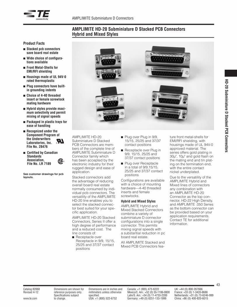
43Catalog 82068 Dimensions are shown for Dimensions are in inches and Canada: +1 (905) 475-6222 UK: +44 (0) 800-267666Revised 4-12 reference purposes only. millimeters unless otherwise Mexico/C. Am.: +52 (0) 55-1106-0800 France: +33 (0) 1-3420-8686
Specifications subject specified. Latin/S. Am.: +54 (0) 11-4733-2200 Netherlands: +31 (0) 73-6246-999www.te.com to change. USA: +1 (800) 522-6752 Germany: +49 (0) 6251-133-1999 China: +86 (0) 400-820-6015
AMPLIMITE Subminiature D Connectors
AMPLIMITE HD-20 Subminiature D Stacked PCB ConnectorsHybrid and Mixed Styles
AMPLIMITE HD-20Subminiature D StackedPCB Connectors are mem-bers of the complete line ofAMPLIMITE Subminiature DConnector family whichhas been accepted by theelectronic industry for theirrugged design and ease ofapplication.
Stacked connectors addthe advantage of reducingoverall board real estatenormally consumed by indi-vidual pcb connectors. Theversatility of the AMPLIMITEHD-20 line enables you toselect the stacked connec-tor best suited for your spe-cific application.
AMPLIMITE HD-20 StackedConnectors, Series II offer ahigh degree of performanceand a reduced cost. Theline consists of: Receptacle overReceptacle in 9/9, 15/15,25/25 and 37/37 contactpositions
Plug over Plug in 9/9,15/15, 25/25 and 37/37contact positions
Receptacle over Plug in9/9, 15/15, 25/25 and37/37 contact positions
Plug over Receptaclein a total of 9/9,15/15,25/25 and 37/37 contactpositions
Configurations are availablewith a choice of mountinghardware—4-40 threadedinserts and femalescrewlocks.
Hybrid and Mixed StylesAMPLIMITE Hybrid andMixed Stacked Connectorscombine a variety ofsubminiature D connectorconfigurations into a singleconnector. This permitsmixing signal speeds witha substantial reduction in pcboard real estate.
All AMPLIMITE Stacked andMixed PCB Connectors fea-
ture front metal-shells forEMI/RFI shielding, withhousings made of UL 94V-0approved material. Theseries offers gold plating in30µ", 10µ" and gold flash onthe mating end and tin plat-ing on the termination end,with the entire contactnickel underplated.
Due to the versatility of theAMPLIMITE Hybrid andMixed lines of connectorsany combination withan AMPLIMITE HD-20Connector as the top con-nector, HD-22 High Density,and AMPLIMITE .050 Seriesas the bottom connector canbe provided based on yourapplication requirements.Contact TE for additionalinformation.
Product Facts Stacked pcb connectorssave board real estate
Wide choice of configura-tions available
Front Metal-Shells forEMI/RFI shielding
Housings made of UL 94V-0rated thermoplastic
Plug connectors have built-in grounding indents
Choice of 4-40 threadedinsert or female screwlockmating hardware
Hybrid styles provide maxi-mum selectivity and permitmixing of signal speeds
Packaged in plastic trays forease of handling
Recognized under theComponent Program ofthe UnderwritersLaboratories, Inc.File No. 28476
Certified by CanadianStandardsAssociation,File No. LR 7189
See customer drawings for pcblayouts.
R
R
HD-20
Subminiature
DStacked
PCBConnectors
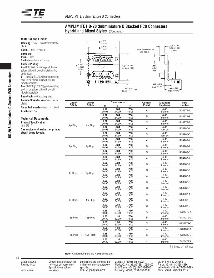
44Catalog 82068 Dimensions are shown for Dimensions are in inches and Canada: +1 (905) 475-6222 UK: +44 (0) 800-267666Revised 4-12 reference purposes only. millimeters unless otherwise Mexico/C. Am.: +52 (0) 55-1106-0800 France: +33 (0) 1-3420-8686
Specifications subject specified. Latin/S. Am.: +54 (0) 11-4733-2200 Netherlands: +31 (0) 73-6246-999www.te.com to change. USA: +1 (800) 522-6752 Germany: +49 (0) 6251-133-1999 China: +86 (0) 400-820-6015
AMPLIMITE Subminiature D Connectors
Note: All part numbers are RoHS compliant.
HD-20Su
bminiature
DStackedPC
BCo
nnectors
AMPLIMITE HD-20 Subminiature D Stacked PCB ConnectorsHybrid and Mixed Styles (Continued)
Material and Finish:Housing—94V-0 rated thermoplastic,blackShell—Steel, tin platedContacts:Pins—BrassSockets—Phosphor bronzeContact Plating:A—Gold flash on mating end, tin onsolder tails with overall nickel platingunderneathB—.000010 [0.00025] gold on matingend, tin on solder tails with overallnickel underplateC—.000030 [0.00076] gold on matingend, tin on solder tails with overallnickel underplateBoardlocks—Brass, tin platedFemale Screwlocks—Brass, nickelplatedThreaded Inserts—Brass, tin platedBrackets—Zinc
Technical Documents:Product Specification108-57517See customer drawings for printedcircuit board layouts.
1.244 ± .015
[31.60 ± 0.38].183[4.64]Ref.
.125 ± .016
[3.18 ± 0.41].380 ± .016
[9.65 ± 0.41]
E ± .010[± 0.25]
D ± .010[± 0.25]
F ± .010[± 0.25]2 Plcs.
Typ.
.318 ± .010
[8.08 ± 0.25]
.228 ± .010
[5.80 ± 0.25]2 Plcs.4-40 Screwlock
See Table
Upper Lower Dimensions Contact Mounting PartD-Sub D-Sub D E F Finish Hardware Number
1.22 .984 .750 A 4-40 1734279-130.95 24.99 19.05 inserts1.22 .984 .750 B 4-40 1734279-230.95 24.99 19.05 inserts1.22 .984 .750 C 4-40 1734279-3
9p Plug / 9p Plug30.95 24.99 19.05 inserts1.22 .984 .750 A 4-40 1734280-130.95 24.99 19.05 fem s/l1.22 .984 .750 C 4-40 1734280-330.95 24.99 19.05 fem s/l1.22 .984 .750 A 4-40 1734282-130.95 24.99 19.05 inserts
9p Plug / 9p Rcpt. 1.22 .984 .750 B 4-40 1734282-230.95 24.99 19.05 inserts1.22 .984 .750 C 4-40 1734282-330.95 24.99 19.05 inserts1.22 .984 .750 A 4-40 1734285-130.95 24.99 19.05 inserts1.22 .984 .750 B 4-40 1734285-230.95 24.99 19.05 inserts1.22 .984 .750 C 4-40 1734285-3
9p Rcpt. / 9p Rcpt.30.95 24.99 19.05 inserts1.22 .984 .750 A 4-40 1734286-130.95 24.99 19.05 fem s/l1.22 .984 .750 B 4-40 1734286-230.95 24.99 19.05 fem s/l1.22 .984 .750 C 4-40 1734286-330.95 24.99 19.05 fem s/l1.22 .984 .750 A 4-40 1734207-130.95 24.99 19.05 inserts
9p Rcpt. / 9p Plug 1.22 .984 .750 B 4-40 1734207-230.95 24.99 19.05 inserts1.22 .984 .750 C 4-40 1734207-330.95 24.99 19.05 inserts1.55 1.31 .750 A 4-40 1-1734279-139.30 33.30 19.05 inserts
15p Plug / 15p Plug 1.55 1.31 .750 B 4-40 1-1734279-239.30 33.30 19.05 inserts1.55 1.31 .750 C 4-40 1-1734279-339.30 33.30 19.05 inserts1.55 1.31 .750 A 4-40 1-1734282-139.30 33.30 19.05 inserts
15p Plug / 15p Rcpt. 1.55 1.31 .750 B 4-40 1-1734282-239.30 33.30 19.05 inserts1.55 1.31 .750 C 4-40 1-1734282-339.30 33.30 19.05 inserts
Continued on next page
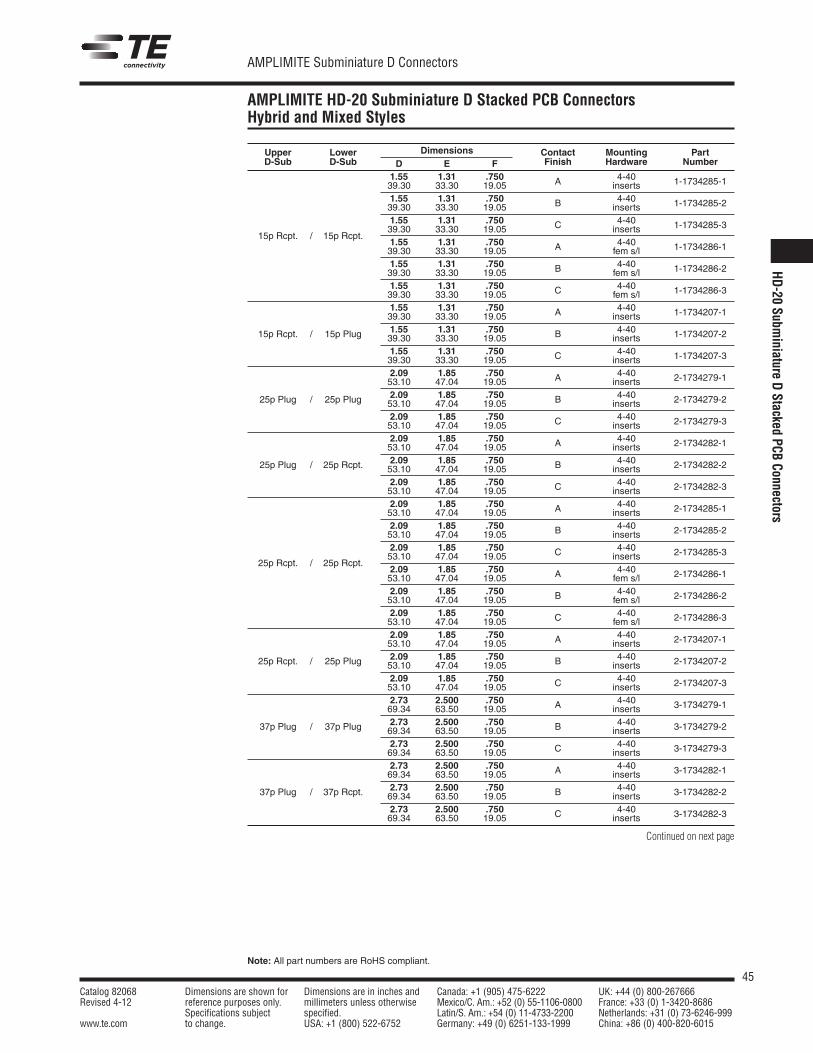
45Catalog 82068 Dimensions are shown for Dimensions are in inches and Canada: +1 (905) 475-6222 UK: +44 (0) 800-267666Revised 4-12 reference purposes only. millimeters unless otherwise Mexico/C. Am.: +52 (0) 55-1106-0800 France: +33 (0) 1-3420-8686
Specifications subject specified. Latin/S. Am.: +54 (0) 11-4733-2200 Netherlands: +31 (0) 73-6246-999www.te.com to change. USA: +1 (800) 522-6752 Germany: +49 (0) 6251-133-1999 China: +86 (0) 400-820-6015
AMPLIMITE Subminiature D Connectors
Note: All part numbers are RoHS compliant.
Upper Lower Dimensions Contact Mounting PartD-Sub D-Sub D E F Finish Hardware Number
1.55 1.31 .750 A 4-40 1-1734285-139.30 33.30 19.05 inserts1.55 1.31 .750 B 4-40 1-1734285-239.30 33.30 19.05 inserts1.55 1.31 .750 C 4-40 1-1734285-3
15p Rcpt. / 15p Rcpt.39.30 33.30 19.05 inserts1.55 1.31 .750 A 4-40 1-1734286-139.30 33.30 19.05 fem s/l1.55 1.31 .750 B 4-40 1-1734286-239.30 33.30 19.05 fem s/l1.55 1.31 .750 C 4-40 1-1734286-339.30 33.30 19.05 fem s/l1.55 1.31 .750 A 4-40 1-1734207-139.30 33.30 19.05 inserts
15p Rcpt. / 15p Plug 1.55 1.31 .750 B 4-40 1-1734207-239.30 33.30 19.05 inserts1.55 1.31 .750 C 4-40 1-1734207-339.30 33.30 19.05 inserts2.09 1.85 .750 A 4-40 2-1734279-153.10 47.04 19.05 inserts
25p Plug / 25p Plug 2.09 1.85 .750 B 4-40 2-1734279-253.10 47.04 19.05 inserts2.09 1.85 .750 C 4-40 2-1734279-353.10 47.04 19.05 inserts2.09 1.85 .750 A 4-40 2-1734282-153.10 47.04 19.05 inserts
25p Plug / 25p Rcpt. 2.09 1.85 .750 B 4-40 2-1734282-253.10 47.04 19.05 inserts2.09 1.85 .750 C 4-40 2-1734282-353.10 47.04 19.05 inserts2.09 1.85 .750 A 4-40 2-1734285-153.10 47.04 19.05 inserts2.09 1.85 .750 B 4-40 2-1734285-253.10 47.04 19.05 inserts2.09 1.85 .750 C 4-40 2-1734285-3
25p Rcpt. / 25p Rcpt.53.10 47.04 19.05 inserts2.09 1.85 .750 A 4-40 2-1734286-153.10 47.04 19.05 fem s/l2.09 1.85 .750 B 4-40 2-1734286-253.10 47.04 19.05 fem s/l2.09 1.85 .750 C 4-40 2-1734286-353.10 47.04 19.05 fem s/l2.09 1.85 .750 A 4-40 2-1734207-153.10 47.04 19.05 inserts
25p Rcpt. / 25p Plug 2.09 1.85 .750 B 4-40 2-1734207-253.10 47.04 19.05 inserts2.09 1.85 .750 C 4-40 2-1734207-353.10 47.04 19.05 inserts2.73 2.500 .750 A 4-40 3-1734279-169.34 63.50 19.05 inserts
37p Plug / 37p Plug 2.73 2.500 .750 B 4-40 3-1734279-269.34 63.50 19.05 inserts2.73 2.500 .750 C 4-40 3-1734279-369.34 63.50 19.05 inserts2.73 2.500 .750 A 4-40 3-1734282-169.34 63.50 19.05 inserts
37p Plug / 37p Rcpt. 2.73 2.500 .750 B 4-40 3-1734282-269.34 63.50 19.05 inserts2.73 2.500 .750 C 4-40 3-1734282-369.34 63.50 19.05 inserts
Continued on next page
AMPLIMITE HD-20 Subminiature D Stacked PCB ConnectorsHybrid and Mixed Styles
HD-20
Subminiature
DStacked
PCBConnectors
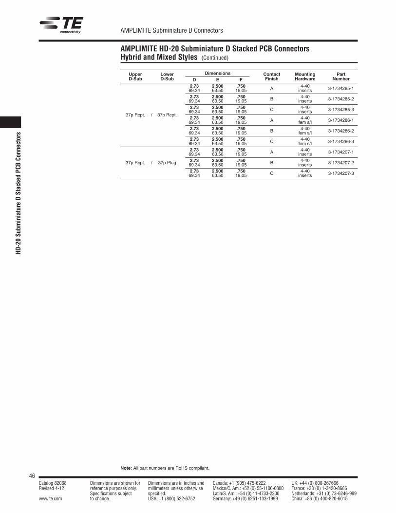
46Catalog 82068 Dimensions are shown for Dimensions are in inches and Canada: +1 (905) 475-6222 UK: +44 (0) 800-267666Revised 4-12 reference purposes only. millimeters unless otherwise Mexico/C. Am.: +52 (0) 55-1106-0800 France: +33 (0) 1-3420-8686
Specifications subject specified. Latin/S. Am.: +54 (0) 11-4733-2200 Netherlands: +31 (0) 73-6246-999www.te.com to change. USA: +1 (800) 522-6752 Germany: +49 (0) 6251-133-1999 China: +86 (0) 400-820-6015
AMPLIMITE Subminiature D Connectors
Note: All part numbers are RoHS compliant.
HD-20Su
bminiature
DStackedPC
BCo
nnectors
Upper Lower Dimensions Contact Mounting PartD-Sub D-Sub D E F Finish Hardware Number
2.73 2.500 .750 A 4-40 3-1734285-169.34 63.50 19.05 inserts2.73 2.500 .750 B 4-40 3-1734285-269.34 63.50 19.05 inserts2.73 2.500 .750 C 4-40 3-1734285-3
37p Rcpt. / 37p Rcpt.69.34 63.50 19.05 inserts2.73 2.500 .750 A 4-40 3-1734286-169.34 63.50 19.05 fem s/l2.73 2.500 .750 B 4-40 3-1734286-269.34 63.50 19.05 fem s/l2.73 2.500 .750 C 4-40 3-1734286-369.34 63.50 19.05 fem s/l2.73 2.500 .750 A 4-40 3-1734207-169.34 63.50 19.05 inserts
37p Rcpt. / 37p Plug 2.73 2.500 .750 B 4-40 3-1734207-269.34 63.50 19.05 inserts2.73 2.500 .750 C 4-40 3-1734207-369.34 63.50 19.05 inserts
AMPLIMITE HD-20 Subminiature D Stacked PCB ConnectorsHybrid and Mixed Styles (Continued)
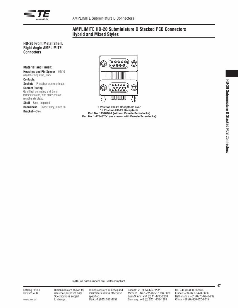
47Catalog 82068 Dimensions are shown for Dimensions are in inches and Canada: +1 (905) 475-6222 UK: +44 (0) 800-267666Revised 4-12 reference purposes only. millimeters unless otherwise Mexico/C. Am.: +52 (0) 55-1106-0800 France: +33 (0) 1-3420-8686
Specifications subject specified. Latin/S. Am.: +54 (0) 11-4733-2200 Netherlands: +31 (0) 73-6246-999www.te.com to change. USA: +1 (800) 522-6752 Germany: +49 (0) 6251-133-1999 China: +86 (0) 400-820-6015
AMPLIMITE Subminiature D Connectors
Note: All part numbers are RoHS compliant.
AMPLIMITE HD-20 Subminiature D Stacked PCB ConnectorsHybrid and Mixed Styles
HD-20 Front Metal Shell,Right-Angle AMPLIMITEConnectors
Material and Finish:Housings and Pin Spacer—94V-0rated thermoplastic, blackContacts:Sockets—Phosphor bronze or brassContact Plating—Gold flash on mating end, tin ontermination end, with entire contactnickel underplatedShell—Steel, tin platedBoardlocks—Copper alloy, plated tinBracket—Steel
9 Position HD-20 Receptacle over15 Position HD-22 Receptacle
Part No. 1734870-1 (without Female Screwlocks)Part No. 1-1734870-1 (as shown, with Female Screwlocks)
HD-20
Subminiature
DStacked
PCBConnectors
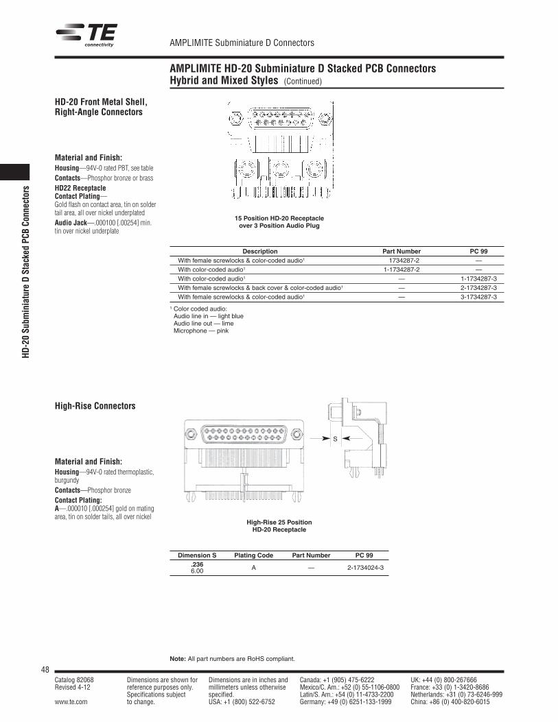
48Catalog 82068 Dimensions are shown for Dimensions are in inches and Canada: +1 (905) 475-6222 UK: +44 (0) 800-267666Revised 4-12 reference purposes only. millimeters unless otherwise Mexico/C. Am.: +52 (0) 55-1106-0800 France: +33 (0) 1-3420-8686
Specifications subject specified. Latin/S. Am.: +54 (0) 11-4733-2200 Netherlands: +31 (0) 73-6246-999www.te.com to change. USA: +1 (800) 522-6752 Germany: +49 (0) 6251-133-1999 China: +86 (0) 400-820-6015
AMPLIMITE Subminiature D Connectors
Note: All part numbers are RoHS compliant.
AMPLIMITE HD-20 Subminiature D Stacked PCB ConnectorsHybrid and Mixed Styles (Continued)
HD-20 Front Metal Shell,Right-Angle Connectors
Material and Finish:Housing—94V-0 rated PBT, see tableContacts—Phosphor bronze or brassHD22 ReceptacleContact Plating—Gold flash on contact area, tin on soldertail area, all over nickel underplatedAudio Jack—.000100 [.00254] min.tin over nickel underplate
15 Position HD-20 Receptacleover 3 Position Audio Plug
Description Part Number PC 99With female screwlocks & color-coded audio1 1734287-2 —With color-coded audio1 1-1734287-2 —With color-coded audio1 — 1-1734287-3With female screwlocks & back cover & color-coded audio1 — 2-1734287-3With female screwlocks & color-coded audio1 — 3-1734287-3
1 Color coded audio:Audio line in — light blueAudio line out — limeMicrophone — pink
High-Rise Connectors
Material and Finish:Housing—94V-0 rated thermoplastic,burgundyContacts—Phosphor bronzeContact Plating:A—.000010 [.000254] gold on matingarea, tin on solder tails, all over nickel
High-Rise 25 PositionHD-20 Receptacle
Dimension S Plating Code Part Number PC 99.236 A — 2-1734024-36.00
S
HD-20Su
bminiature
DStackedPC
BCo
nnectors
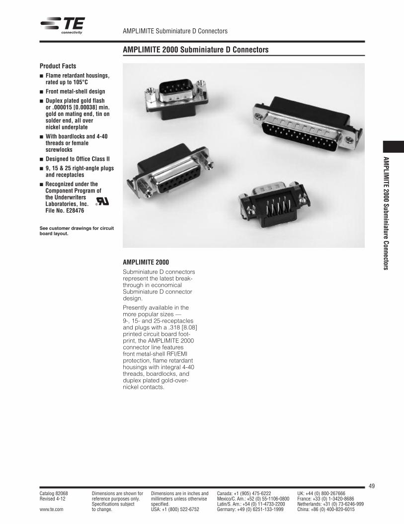
49Catalog 82068 Dimensions are shown for Dimensions are in inches and Canada: +1 (905) 475-6222 UK: +44 (0) 800-267666Revised 4-12 reference purposes only. millimeters unless otherwise Mexico/C. Am.: +52 (0) 55-1106-0800 France: +33 (0) 1-3420-8686
Specifications subject specified. Latin/S. Am.: +54 (0) 11-4733-2200 Netherlands: +31 (0) 73-6246-999www.te.com to change. USA: +1 (800) 522-6752 Germany: +49 (0) 6251-133-1999 China: +86 (0) 400-820-6015
AMPLIMITE Subminiature D Connectors
AMPLIMITE 2000 Subminiature D Connectors
AMPLIMITE 2000Subminiature D connectorsrepresent the latest break-through in economicalSubminiature D connectordesign.
Presently available in themore popular sizes —9-, 15- and 25-receptaclesand plugs with a .318 [8.08]printed circuit board foot-print, the AMPLIMITE 2000connector line featuresfront metal-shell RFI/EMIprotection, flame retardanthousings with integral 4-40threads, boardlocks, andduplex plated gold-over-nickel contacts.
Product Facts Flame retardant housings,
rated up to 105°C
Front metal-shell design
Duplex plated gold flashor .000015 [0.00038] min.gold on mating end, tin onsolder end, all overnickel underplate
With boardlocks and 4-40threads or femalescrewlocks
Designed to Office Class II
9, 15 & 25 right-angle plugsand receptacles
Recognized under theComponent Program ofthe UnderwritersLaboratories, Inc.File No. E28476
See customer drawings for circuitboard layout.
R
AMPLIM
ITE2000
Subminiature
Connectors
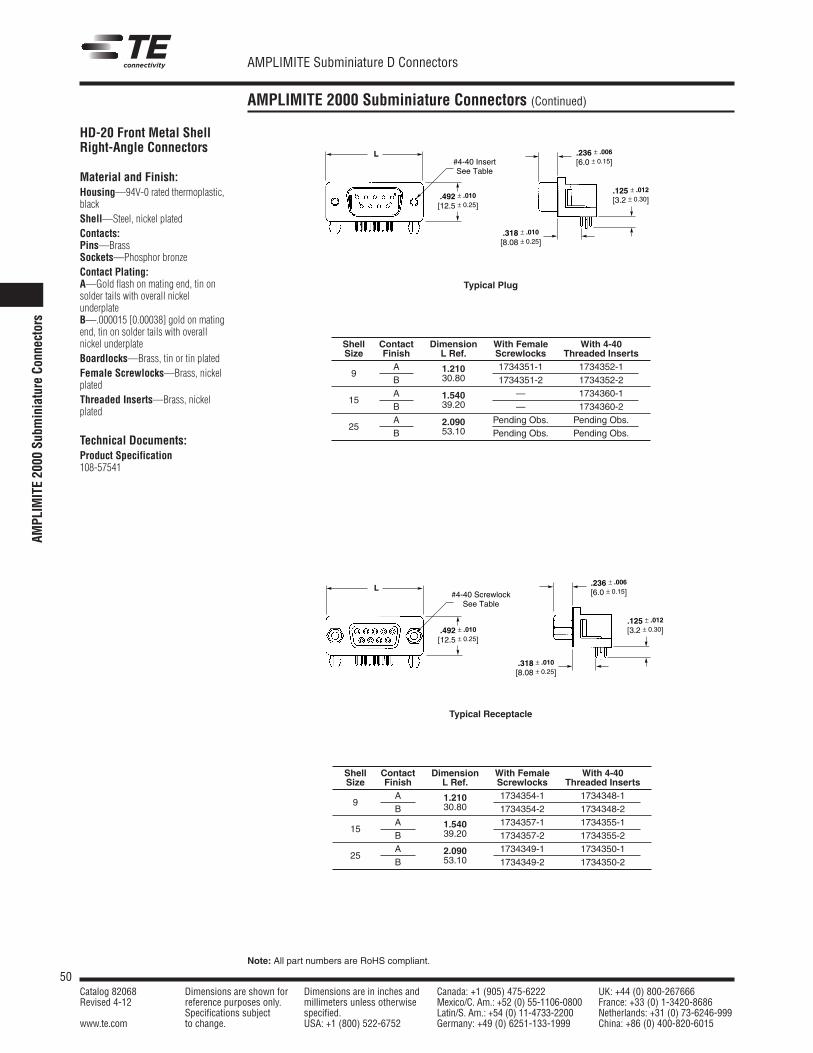
50Catalog 82068 Dimensions are shown for Dimensions are in inches and Canada: +1 (905) 475-6222 UK: +44 (0) 800-267666Revised 4-12 reference purposes only. millimeters unless otherwise Mexico/C. Am.: +52 (0) 55-1106-0800 France: +33 (0) 1-3420-8686
Specifications subject specified. Latin/S. Am.: +54 (0) 11-4733-2200 Netherlands: +31 (0) 73-6246-999www.te.com to change. USA: +1 (800) 522-6752 Germany: +49 (0) 6251-133-1999 China: +86 (0) 400-820-6015
AMPLIMITE Subminiature D Connectors
Note: All part numbers are RoHS compliant.
AMPLIMITE 2000 Subminiature Connectors (Continued)
.492 ± .010
[12.5 ± 0.25]
#4-40 Insert See Table
L
.125 ± .012 [3.2 ± 0.30]
.236 ± .006 [6.0 ± 0.15]
.318 ± .010
[8.08 ± 0.25]
Typical Plug
Shell Contact Dimension With Female With 4-40Size Finish L Ref. Screwlocks Threaded Inserts
9A 1.210 1734351-1 1734352-1B 30.80 1734351-2 1734352-2
15A 1.540 — 1734360-1B 39.20 — 1734360-2
25A 2.090 Pending Obs. Pending Obs.B 53.10 Pending Obs. Pending Obs.
Shell Contact Dimension With Female With 4-40Size Finish L Ref. Screwlocks Threaded Inserts
9A 1.210 1734354-1 1734348-1B 30.80 1734354-2 1734348-2
15A 1.540 1734357-1 1734355-1B 39.20 1734357-2 1734355-2
25A 2.090 1734349-1 1734350-1B 53.10 1734349-2 1734350-2
.492 ± .010
[12.5 ± 0.25]
#4-40 ScrewlockSee Table
L
.125 ± .012
[3.2 ± 0.30]
.236 ± .006
[6.0 ± 0.15]
.318 ± .010
[8.08 ± 0.25]
Typical Receptacle
HD-20 Front Metal ShellRight-Angle Connectors
Material and Finish:Housing—94V-0 rated thermoplastic,blackShell—Steel, nickel platedContacts:Pins—BrassSockets—Phosphor bronzeContact Plating:A—Gold flash on mating end, tin onsolder tails with overall nickelunderplateB—.000015 [0.00038] gold on matingend, tin on solder tails with overallnickel underplateBoardlocks—Brass, tin or tin platedFemale Screwlocks—Brass, nickelplatedThreaded Inserts—Brass, nickelplated
Technical Documents:Product Specification108-57541
AMPL
IMITE2000
Subm
iniature
Connectors

51Catalog 82068 Dimensions are shown for Dimensions are in inches and Canada: +1 (905) 475-6222 UK: +44 (0) 800-267666Revised 4-12 reference purposes only. millimeters unless otherwise Mexico/C. Am.: +52 (0) 55-1106-0800 France: +33 (0) 1-3420-8686
Specifications subject specified. Latin/S. Am.: +54 (0) 11-4733-2200 Netherlands: +31 (0) 73-6246-999www.te.com to change. USA: +1 (800) 522-6752 Germany: +49 (0) 6251-133-1999 China: +86 (0) 400-820-6015
AMPLIMITE Subminiature D Connectors
Note: All part numbers are RoHS compliant.
HD-20 and HD-22 Slimline Connectors
9 Position PlugPart Number 1734340-1
2 Rows of Soldertails
Material and Finish:Housing—94V-0 rated thermoplastic,blackShell—Low carbon steel, nickel platedContacts—Phosphor bronze or brassContact Plating—Gold flash onmating area; .000100 [0.00254] min.tin on solder tail area; overall .000050[0.00127] min. nickelunderplateBoardlocks—Brass, tin plated overnickel underplateThreaded Inserts—Brass, nickelplated
Technical Documents:Product Specification108-57541
1 Row of Soldertails
Material and Finish:Housing—94V-0 rated thermoplastic,blackShell—Low carbon steel, nickel platedContacts—BrassContact Plating—.000015 [0.00038]min. gold on mating area; .000100[0.00254] min. tin on solder tail area;overall .000050 [0.00127] min. nickelunderplateBoardlocks—Brass, tin plated overnickel underplateThreaded Inserts—Brass, nickelplated
Technical Documents:Product Specification108-57541
15 Position VESA Receptacle HD-22Part Number 1734341-1
15 Position VESA Receptacle HD-22Part Number 1734335-1
HD-20
andHD-22
Slimline
Connectors
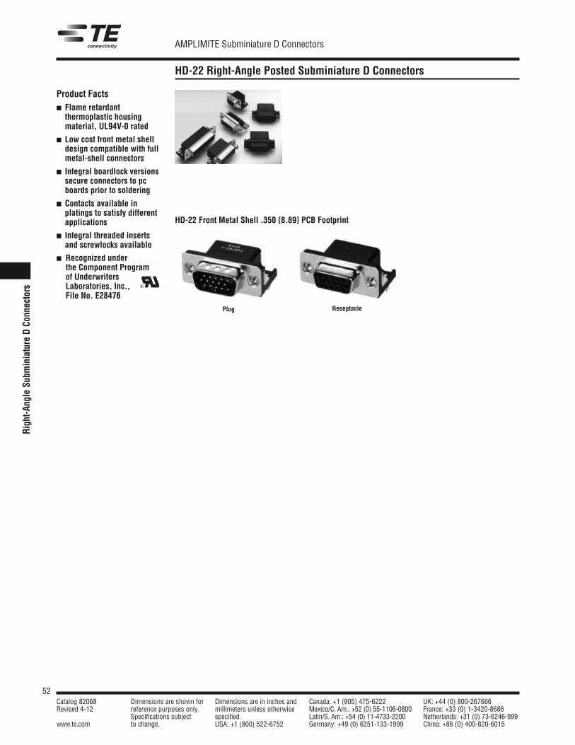
52Catalog 82068 Dimensions are shown for Dimensions are in inches and Canada: +1 (905) 475-6222 UK: +44 (0) 800-267666Revised 4-12 reference purposes only. millimeters unless otherwise Mexico/C. Am.: +52 (0) 55-1106-0800 France: +33 (0) 1-3420-8686
Specifications subject specified. Latin/S. Am.: +54 (0) 11-4733-2200 Netherlands: +31 (0) 73-6246-999www.te.com to change. USA: +1 (800) 522-6752 Germany: +49 (0) 6251-133-1999 China: +86 (0) 400-820-6015
AMPLIMITE Subminiature D Connectors
Right-AngleSu
bminiature
DCo
nnectors
HD-22 Right-Angle Posted Subminiature D Connectors
Product Facts Flame retardantthermoplastic housingmaterial, UL94V-0 rated
Low cost front metal shelldesign compatible with fullmetal-shell connectors
Integral boardlock versionssecure connectors to pcboards prior to soldering
Contacts available inplatings to satisfy differentapplications
Integral threaded insertsand screwlocks available
Recognized underthe Component Programof UnderwritersLaboratories, Inc.,File No. E28476
R
Plug Receptacle
HD-22 Front Metal Shell .350 [8.89] PCB Footprint
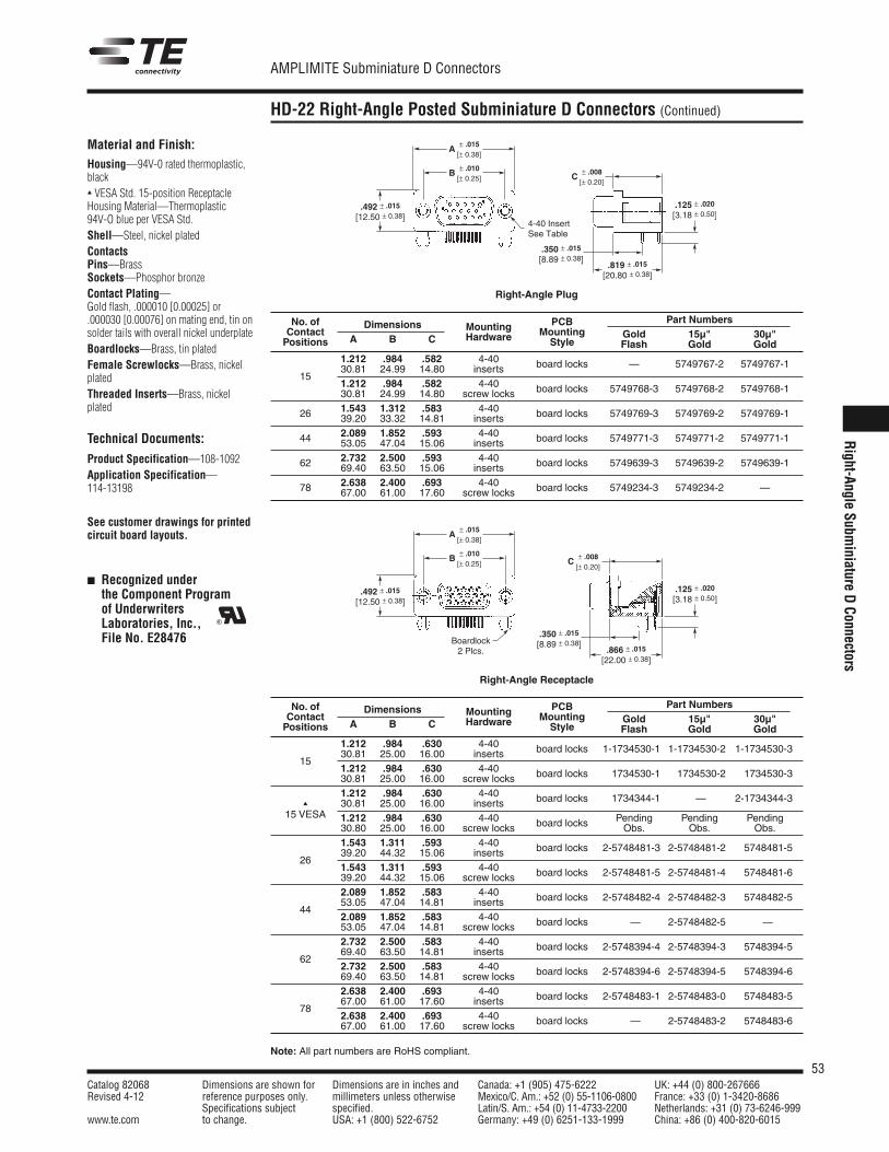
53Catalog 82068 Dimensions are shown for Dimensions are in inches and Canada: +1 (905) 475-6222 UK: +44 (0) 800-267666Revised 4-12 reference purposes only. millimeters unless otherwise Mexico/C. Am.: +52 (0) 55-1106-0800 France: +33 (0) 1-3420-8686
Specifications subject specified. Latin/S. Am.: +54 (0) 11-4733-2200 Netherlands: +31 (0) 73-6246-999www.te.com to change. USA: +1 (800) 522-6752 Germany: +49 (0) 6251-133-1999 China: +86 (0) 400-820-6015
AMPLIMITE Subminiature D Connectors
Note: All part numbers are RoHS compliant.
HD-22 Right-Angle Posted Subminiature D Connectors (Continued)
Material and Finish:Housing—94V-0 rated thermoplastic,black VESA Std. 15-position ReceptacleHousing Material—Thermoplastic94V-O blue per VESA Std.Shell—Steel, nickel platedContactsPins—BrassSockets—Phosphor bronzeContact Plating—Gold flash, .000010 [0.00025] or.000030 [0.00076] on mating end, tin onsolder tails with overall nickel underplateBoardlocks—Brass, tin platedFemale Screwlocks—Brass, nickelplatedThreaded Inserts—Brass, nickelplated
Technical Documents:
Product Specification—108-1092Application Specification—114-13198
See customer drawings for printedcircuit board layouts.
Recognized underthe Component Programof UnderwritersLaboratories, Inc.,File No. E28476
R
.492 ± .015
[12.50 ± 0.38].125 ± .020
[3.18 ± 0.50]
.350 ± .015
[8.89 ± 0.38].819 ± .015
[20.80 ± 0.38]
4-40 InsertSee Table
A ± .015[± 0.38]
B ± .010[± 0.25] C ± .008
[± 0.20]
Right-Angle Plug
.492 ± .015
[12.50 ± 0.38]
.125 ± .020
[3.18 ± 0.50]
.350 ± .015
[8.89 ± 0.38].866 ± .015
[22.00 ± 0.38]
Boardlock2 Plcs.
A ± .015[± 0.38]
B ± .010[± 0.25] C ± .008
[± 0.20]
Right-Angle Receptacle
No. of Dimensions PCB Part NumbersContact
A B CMounting Mounting Gold 15µ" 30µ"
Positions Hardware Style Flash Gold Gold1.212 .984 .582 4-40 board locks — 5749767-2 5749767-1
1530.81 24.99 14.80 inserts1.212 .984 .582 4-40 board locks 5749768-3 5749768-2 5749768-130.81 24.99 14.80 screw locks
26 1.543 1.312 .583 4-40 board locks 5749769-3 5749769-2 5749769-139.20 33.32 14.81 inserts
44 2.089 1.852 .593 4-40 board locks 5749771-3 5749771-2 5749771-153.05 47.04 15.06 inserts
62 2.732 2.500 .593 4-40 board locks 5749639-3 5749639-2 5749639-169.40 63.50 15.06 inserts
78 2.638 2.400 .693 4-40 board locks 5749234-3 5749234-2 —67.00 61.00 17.60 screw locks
No. of Dimensions PCB Part NumbersContact
A B CMounting Mounting Gold 15µ" 30µ"
Positions Hardware Style Flash Gold Gold1.212 .984 .630 4-40 board locks 1-1734530-1 1-1734530-2 1-1734530-3
1530.81 25.00 16.00 inserts1.212 .984 .630 4-40 board locks 1734530-1 1734530-2 1734530-330.81 25.00 16.00 screw locks1.212 .984 .630 4-40 board locks 1734344-1 — . 2-1734344-3
30.81 25.00 16.00 inserts15 VESA 1.212 .984 .630 4-40 board locks Pending Pending Pending
30.80 25.00 16.00 screw locks Obs. Obs. Obs.1.543 1.311 .593 4-40 board locks 2-5748481-3 2-5748481-2 5748481-5
2639.20 44.32 15.06 inserts1.543 1.311 .593 4-40 board locks 2-5748481-5 2-5748481-4 5748481-639.20 44.32 15.06 screw locks2.089 1.852 .583 4-40 board locks 2-5748482-4 2-5748482-3 5748482-5
4453.05 47.04 14.81 inserts2.089 1.852 .583 4-40 board locks — . 2-5748482-5 — .53.05 47.04 14.81 screw locks2.732 2.500 .583 4-40 board locks 2-5748394-4 2-5748394-3 5748394-5
6269.40 63.50 14.81 inserts2.732 2.500 .583 4-40 board locks 2-5748394-6 2-5748394-5 5748394-669.40 63.50 14.81 screw locks2.638 2.400 .693 4-40 board locks 2-5748483-1 2-5748483-0 5748483-5
7867.00 61.00 17.60 inserts2.638 2.400 .693 4-40 board locks — . 2-5748483-2 5748483-667.00 61.00 17.60 screw locks
Right-Angle
Subminiature
DConnectors
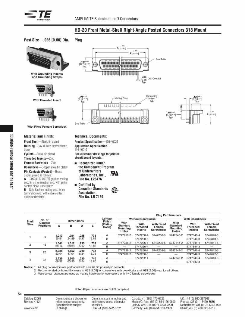
54Catalog 82068 Dimensions are shown for Dimensions are in inches and Canada: +1 (905) 475-6222 UK: +44 (0) 800-267666Revised 4-12 reference purposes only. millimeters unless otherwise Mexico/C. Am.: +52 (0) 55-1106-0800 France: +33 (0) 1-3420-8686
Specifications subject specified. Latin/S. Am.: +54 (0) 11-4733-2200 Netherlands: +31 (0) 73-6246-999www.te.com to change. USA: +1 (800) 522-6752 Germany: +49 (0) 6251-133-1999 China: +86 (0) 400-820-6015
AMPLIMITE Subminiature D Connectors
Note: All part numbers are RoHS compliant.
.318
[8.08]
BoardMountFootprint
HD-20 Front Metal-Shell Right-Angle Posted Connectors 318 Mount
Post Size—.026 [0.66] Dia. Plug
With Grounding Indentsand Grounding Straps
With Threaded Insert
With Fixed Female Screwlock
D
.494±.015[12.55±0.38]Typ.
.375±.010[9.52±0.25]Typ.
.125±.015[3.18±0.15]Typ.
.318±.015[8.08±0.38]Typ.
.026[0.66] Dia. Contact
Typ.
Mating Face
See Table
See Table
GroundingIndentTyp.
A± .015
[± 0.381]
E± .015
[± 0.381]
B± .010
[± 0.254]
Technical Documents:Product Specification—108-40025Application Specification—114-40010See customer drawings for printedcircuit board layouts.
Recognized underthe Component Programof UnderwritersLaboratories, Inc.,File No. E28476
Certified byCanadian StandardsAssociation,File No. LR 7189
R
R
Material and Finish:Front Shell—Steel, tin platedHousing—94V-0 rated thermoplastic,blackEyelets—Brass, tin platedThreaded Inserts—ZincFemale Screwlock—ZincBoardlocks—Copper alloy, tin platedPin Contacts (Posted)—Brass,duplex plated as follows:A—.000030 [0.00076] gold on matingend, tin on termination end, with entirecontact nickel underplatedB—Gold flash on mating end, tin ontermination end, with entire contactnickel underplated
Plug Part NumbersWithout Boardlocks With BoardlocksContact
With WithNo. of Finish
Standard With With Fixed Standard With With FixedShell Contact
Dimensions(Plating
Mounting Threaded Female Mounting Threaded FemaleSize Positions A B D E Code)
Holes Inserts Screwlocks Holes Inserts Screwlocks
1.213 .984 .235 .733 A 5747250-2 5747250-4 5747250-6 5747840-2 5747840-4 5747840-61 9 30.81 24.99 5.97 18.62 B — 5747250-3 — — 5747840-3 5747840-5
1.541 1.312 .235 .733 A 5747236-2 5747236-4 5747236-6 5747841-2 5747841-4 5747841-62 15 39.14 33.33 5.97 18.62 B — 5747236-4 — — 5747841-3 —
2.088 1.852 .230 .738 A 5747238-2 5747238-4 5747238-6 5747842-2 5747842-4 5747842-63 25 53.04 47.04 5.84 18.75 B 5747238-2 5747238-3 — — 5747842-3 5747842-5
2.729 2.500 .230 .740 A — 5747252-4 — 5747843-2 5747843-4 5747843-64 37 69.32 63.50 5.84 18.80 B — — — — 5747843-3 —
Notes: 1. All plug connectors are preloaded with size 20 DF posted pin contacts.2. Recommended pc board thickness is .062 [1.58] for connectors with boardlocks and .093 [2.36] max. for all others.3. Male screw retainers are used as mating hardware for connectors with 4-40 female screwlocks.
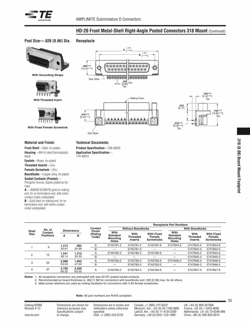
55Catalog 82068 Dimensions are shown for Dimensions are in inches and Canada: +1 (905) 475-6222 UK: +44 (0) 800-267666Revised 4-12 reference purposes only. millimeters unless otherwise Mexico/C. Am.: +52 (0) 55-1106-0800 France: +33 (0) 1-3420-8686
Specifications subject specified. Latin/S. Am.: +54 (0) 11-4733-2200 Netherlands: +31 (0) 73-6246-999www.te.com to change. USA: +1 (800) 522-6752 Germany: +49 (0) 6251-133-1999 China: +86 (0) 400-820-6015
AMPLIMITE Subminiature D Connectors
Note: All part numbers are RoHS compliant.
HD-20 Front Metal-Shell Right-Angle Posted Connectors 318 Mount (Continued)
Post Size—.026 [0.66] Dia. Receptacle
.494±.015[12.55±0.38]
.318±.015[8.08±0.38]
.243[6.17]
.375±.010[9.53±0.25]
Mating Face
See Table
See Table
.026[0.66] Dia.
Typ.
With Grounding Straps
With Fixed Female Screwlock
With Threaded Insert
A± .015
[± 0.381]
B± .010
[± 0.254]
Typ.
.125±.015[3.18±0.38]Typ.
.740±.015[18.80±0.38]
Typ.
Material and Finish:Front Shell—Steel, tin platedHousing—94V-0 rated thermoplastic,blackEyelets—Brass, tin platedThreaded Inserts—ZincFemale Screwlock—ZincBoardlocks—Copper alloy, tin platedSocket Contacts (Posted)—Phosphor bronze, duplex plated as fol-lows:A—.000030 [0.00076] gold on matingend, tin on termination end, with entirecontact nickel underplatedB—Gold flash on mating end, tin ontermination end, with entire contactnickel underplated
Technical Documents:Product Specification—108-40025Application Specification—114-40010
Notes: 1. All receptacle connectors are preloaded with size 20 DF posted socket contacts.2. Recommended pc board thickness is .062 [1.58] for connectors with boardlocks and .093 [2.36] max. for all others.3. Male screw retainers are used as mating hardware for connectors with 4-40 female screwlocks.
Receptacle Part NumbersWithout Boardlocks With BoardlocksContact
With WithNo. of Finish
Standard With With Fixed Standard With With FixedShell Contact
Dimensions(Plating
Mounting Threaded Female Mounting Threaded FemaleSize Positions A B Code)
Holes Inserts Screwlocks Holes Inserts Screwlocks
1.213 .984 A 5745781-2 5745781-4 5745781-6 5747844-2 5747844-4 5747844-61 9 30.81 24.99 B — 5745781-3 — — 5747844-3 5747844-5
1.541 1.312 A 5745782-2 5745782-4 5745782-6 — 5747845-4 5747845-62 15 39.14 33.33 B — — — — 5747845-3 5747845-5
2.088 1.852 A 5745783-2 5745783-4 5745783-6 5747846-2 5747846-4 5747846-63 25 53.04 47.04 B — 5745783-3 5745783-5 — 5747846-3 5747846-5
2.729 2.500 A 5745784-2 5745784-4 5745784-6 — 5747847-4 5747847-64 3769.32 63.50
.318[8.08]Board
MountFootprint
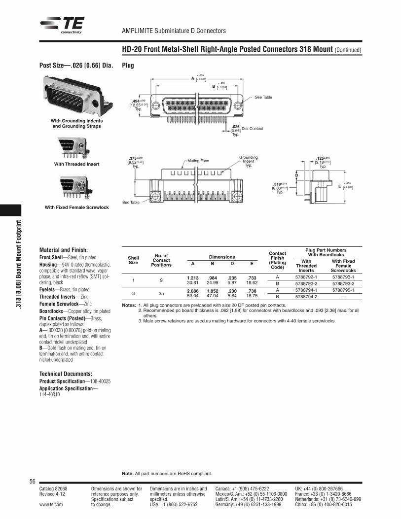
56Catalog 82068 Dimensions are shown for Dimensions are in inches and Canada: +1 (905) 475-6222 UK: +44 (0) 800-267666Revised 4-12 reference purposes only. millimeters unless otherwise Mexico/C. Am.: +52 (0) 55-1106-0800 France: +33 (0) 1-3420-8686
Specifications subject specified. Latin/S. Am.: +54 (0) 11-4733-2200 Netherlands: +31 (0) 73-6246-999www.te.com to change. USA: +1 (800) 522-6752 Germany: +49 (0) 6251-133-1999 China: +86 (0) 400-820-6015
AMPLIMITE Subminiature D Connectors
Note: All part numbers are RoHS compliant.
.318
[8.08]
BoardMountFootprint
HD-20 Front Metal-Shell Right-Angle Posted Connectors 318 Mount (Continued)
Material and Finish:Front Shell—Steel, tin platedHousing—94V-0 rated thermoplastic,compatible with standard wave, vaporphase, and infra-red reflow (SMT) sol-dering, blackEyelets—Brass, tin platedThreaded Inserts—ZincFemale Screwlock—ZincBoardlocks—Copper alloy, tin platedPin Contacts (Posted)—Brass,duplex plated as follows:A—.000030 [0.00076] gold on matingend, tin on termination end, with entirecontact nickel underplatedB—Gold flash on mating end, tin ontermination end, with entire contactnickel underplated
Technical Documents:Product Specification—108-40025Application Specification—114-40010
Plug Part Numbers
Shell No. of DimensionsContact With Boardlocks
Size Contact FinishWith With Fixed
Positions A B D E (PlatingThreaded FemaleCode)Inserts Screwlocks
1 9 1.213 .984 .235 .733 A 5788792-1 5788793-130.81 24.99 5.97 18.62 B 5788792-2 5788793-2
3 25 2.088 1.852 .230 .738 A 5788794-1 5788795-153.04 47.04 5.84 18.75 B 5788794-2 —
Notes: 1. All plug connectors are preloaded with size 20 DF posted pin contacts.2. Recommended pc board thickness is .062 [1.58] for connectors with boardlocks and .093 [2.36] max. for allothers.
3. Male screw retainers are used as mating hardware for connectors with 4-40 female screwlocks.
Post Size—.026 [0.66] Dia. Plug
With Grounding Indentsand Grounding Straps
With Threaded Insert
With Fixed Female Screwlock
D
.494±.015[12.55±0.38]Typ.
.375±.010[9.52±0.25]Typ.
.125±.015[3.18±0.15]Typ.
.318±.015[8.08±0.38]Typ.
.026[0.66] Dia. Contact
Typ.
Mating Face
See Table
See Table
GroundingIndentTyp.
A± .015
[± 0.381]
E± .015
[± 0.381]
B± .010
[± 0.254]
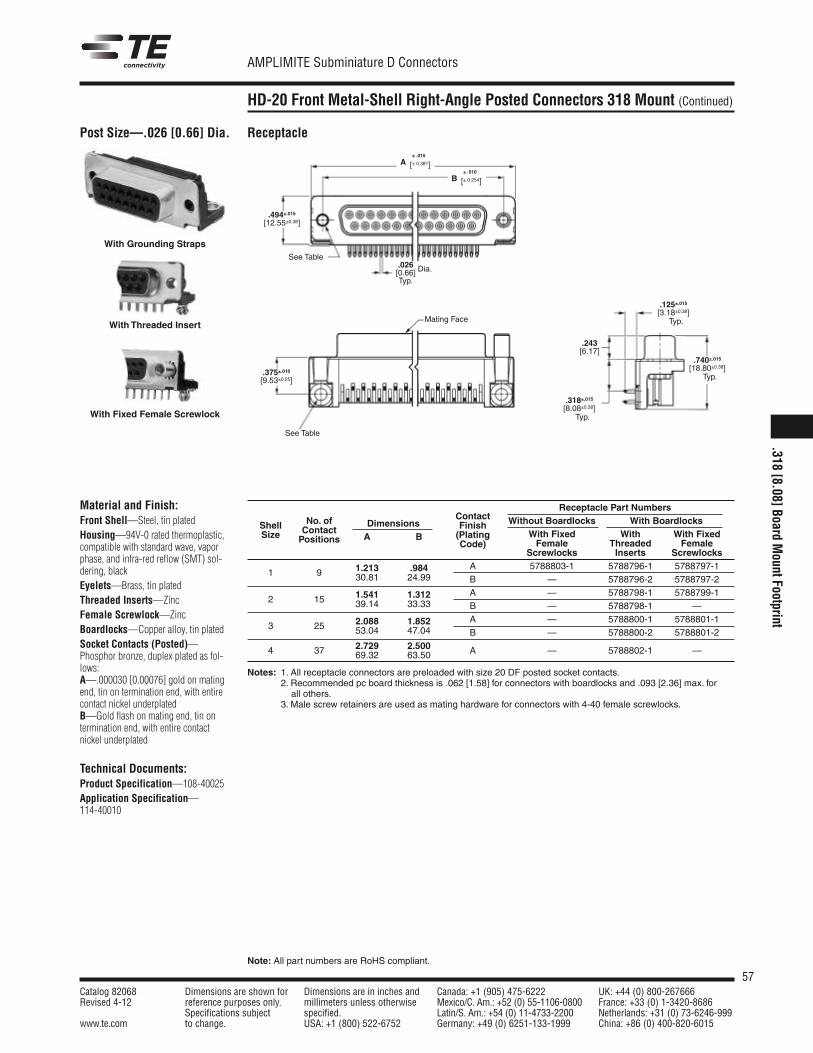
57Catalog 82068 Dimensions are shown for Dimensions are in inches and Canada: +1 (905) 475-6222 UK: +44 (0) 800-267666Revised 4-12 reference purposes only. millimeters unless otherwise Mexico/C. Am.: +52 (0) 55-1106-0800 France: +33 (0) 1-3420-8686
Specifications subject specified. Latin/S. Am.: +54 (0) 11-4733-2200 Netherlands: +31 (0) 73-6246-999www.te.com to change. USA: +1 (800) 522-6752 Germany: +49 (0) 6251-133-1999 China: +86 (0) 400-820-6015
AMPLIMITE Subminiature D Connectors
Note: All part numbers are RoHS compliant.
HD-20 Front Metal-Shell Right-Angle Posted Connectors 318 Mount (Continued)
Material and Finish:Front Shell—Steel, tin platedHousing—94V-0 rated thermoplastic,compatible with standard wave, vaporphase, and infra-red reflow (SMT) sol-dering, blackEyelets—Brass, tin platedThreaded Inserts—ZincFemale Screwlock—ZincBoardlocks—Copper alloy, tin platedSocket Contacts (Posted)—Phosphor bronze, duplex plated as fol-lows:A—.000030 [0.00076] gold on matingend, tin on termination end, with entirecontact nickel underplatedB—Gold flash on mating end, tin ontermination end, with entire contactnickel underplated
Technical Documents:Product Specification—108-40025Application Specification—114-40010
Receptacle Part Numbers
Shell No. of DimensionsContact Without Boardlocks With Boardlocks
Size ContactA B
FinishWith Fixed With With FixedPositions (Plating
Female Threaded FemaleCode)Screwlocks Inserts Screwlocks
1 9 1.213 .984 A 5788803-1 5788796-1 5788797-130.81 24.99 B — 5788796-2 5788797-2
2 15 1.541 1.312 A — 5788798-1 5788799-139.14 33.33 B — 5788798-1 —
3 25 2.088 1.852 A — 5788800-1 5788801-153.04 47.04 B — 5788800-2 5788801-2
4 37 2.729 2.500 A — 5788802-1 —69.32 63.50
Notes: 1. All receptacle connectors are preloaded with size 20 DF posted socket contacts.2. Recommended pc board thickness is .062 [1.58] for connectors with boardlocks and .093 [2.36] max. forall others.
3. Male screw retainers are used as mating hardware for connectors with 4-40 female screwlocks.
Post Size—.026 [0.66] Dia. Receptacle
.494±.015[12.55±0.38]
.318±.015[8.08±0.38]
.243[6.17]
.375±.010[9.53±0.25]
Mating Face
See Table
See Table
.026[0.66] Dia.
Typ.
With Grounding Straps
With Fixed Female Screwlock
With Threaded Insert
A± .015
[± 0.381]
B± .010
[± 0.254]
Typ.
.125±.015[3.18±0.38]Typ.
.740±.015[18.80±0.38]
Typ.
.318[8.08]Board
MountFootprint
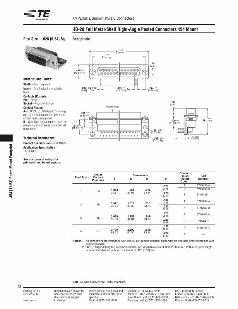
58Catalog 82068 Dimensions are shown for Dimensions are in inches and Canada: +1 (905) 475-6222 UK: +44 (0) 800-267666Revised 4-12 reference purposes only. millimeters unless otherwise Mexico/C. Am.: +52 (0) 55-1106-0800 France: +33 (0) 1-3420-8686
Specifications subject specified. Latin/S. Am.: +54 (0) 11-4733-2200 Netherlands: +31 (0) 73-6246-999www.te.com to change. USA: +1 (800) 522-6752 Germany: +49 (0) 6251-133-1999 China: +86 (0) 400-820-6015
AMPLIMITE Subminiature D Connectors
Note: All part numbers are RoHS compliant.
.454
[11.53]B
oard
MountFootprint
HD-20 Full Metal-Shell Right-Angle Posted Connectors 454 Mount
Receptacle
ContactNo. of Dimensions Finish PartShell Size ContactA B D E (Plating NumberPositions Code)
.125 A 5745438-4
1 9 1.213 .984 .915 3.18 B 5745438-330.81 24.99 23.24 .220
5.59 B 5745438-1
.125 A 5745439-42 15 1.541 1.312 915 3.18
39.14 33.33 23.24 .220 A 5745439-25.59.125 A 5745440-4
3 25 2.088 1.852 .919 3.1853.04 47.04 23.34 .220
5.59 B 5745440-1
.125 A 5745441-44 37 2.729 2.500 .919 3.18
69.32 63.50 23.34 .2205.59 B —
Notes: 1. All connectors are preloaded with size 20 DF posted contacts; plugs with pin contacts and receptacles with3. socket contacts.2. .125 [3.18] post length is recommended for pc board thickness of .093 [2.36] max.; .220 [5.59] post lengthis recommended for pc board thickness of .125 [3.18] max.
Mating Face
Sq. PostTyp.
.025[0.64]
.112[2.84]
.494±.015[12.55±0.38]
.274±.015[6.96±0.38]
.109±.010[2.77±0.25]
Typ.
.120[3.05]
Dia.Typ.
.120[3.05]
Dia.Typ.
.269±.010[6.83±0.25]
.510±.010[12.95±0.25]
+.030 [0.762]-0.15 [0.381]E
.454±.015[11.53±0.38]
A± .015
[± 0.381]
D± .015
[± 0.381]
B± .010
[± 0.254]
.243[6.17]
Material and Finish:Shell—Steel, tin platedInsert—94V-0 rated thermoplastic,blackContacts (Posted):Pin—BrassSocket—Phosphor bronzeContact Plating:A—.000030 [0.00076] gold on matingend, tin on termination end, with entirecontact nickel underplatedB—Gold flash on mating end, tin on ter-mination end, with entire contact nickelunderplated
Technical Documents:Product Specification—108-40025Application Specification—114-40013
See customer drawings forprinted circuit board layouts.
Post Size—.025 [0.64] Sq.
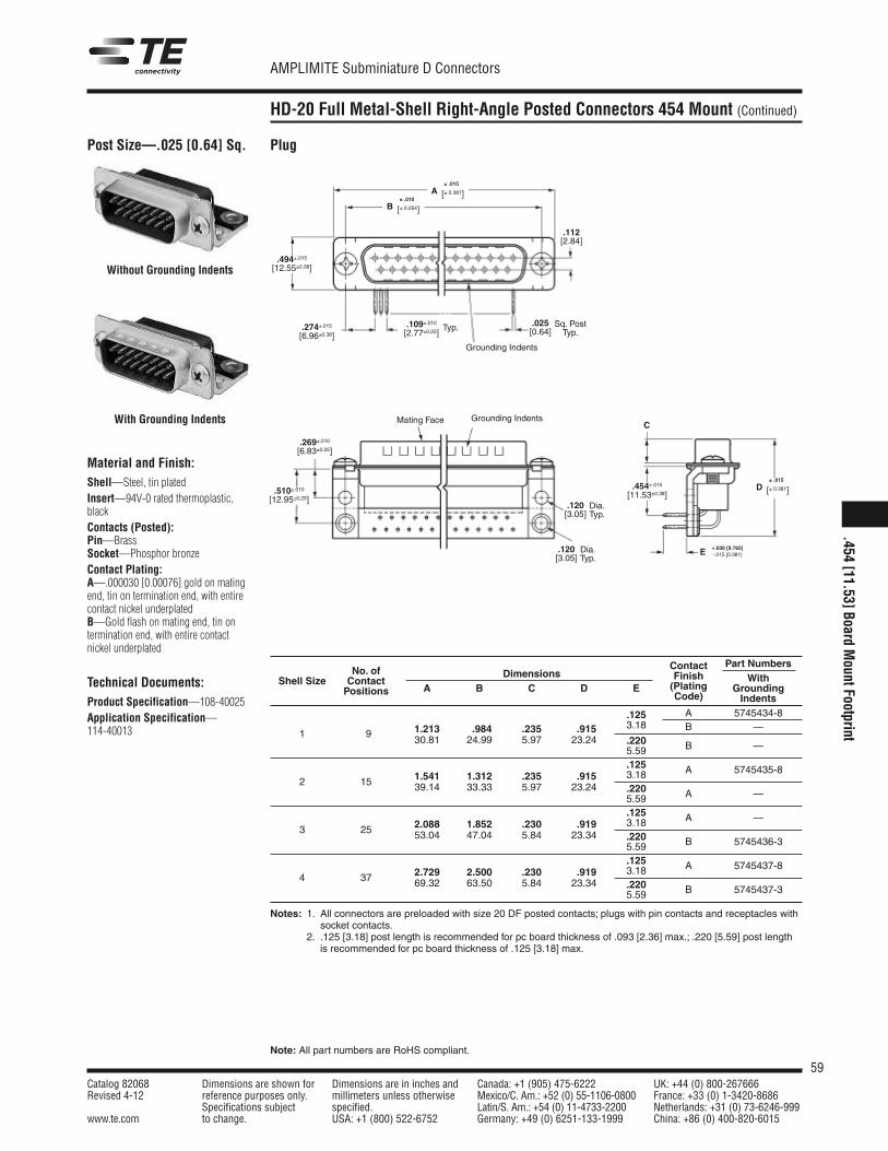
59Catalog 82068 Dimensions are shown for Dimensions are in inches and Canada: +1 (905) 475-6222 UK: +44 (0) 800-267666Revised 4-12 reference purposes only. millimeters unless otherwise Mexico/C. Am.: +52 (0) 55-1106-0800 France: +33 (0) 1-3420-8686
Specifications subject specified. Latin/S. Am.: +54 (0) 11-4733-2200 Netherlands: +31 (0) 73-6246-999www.te.com to change. USA: +1 (800) 522-6752 Germany: +49 (0) 6251-133-1999 China: +86 (0) 400-820-6015
AMPLIMITE Subminiature D Connectors
Note: All part numbers are RoHS compliant.
HD-20 Full Metal-Shell Right-Angle Posted Connectors 454 Mount (Continued)
Plug
Material and Finish:Shell—Steel, tin platedInsert—94V-0 rated thermoplastic,blackContacts (Posted):Pin—BrassSocket—Phosphor bronzeContact Plating:A—.000030 [0.00076] gold on matingend, tin on termination end, with entirecontact nickel underplatedB—Gold flash on mating end, tin ontermination end, with entire contactnickel underplated
Technical Documents:Product Specification—108-40025Application Specification—114-40013
Without Grounding Indents
With Grounding Indents
Grounding Indents
Sq. PostTyp.
.120[3.05]
.025[0.64]
.112[2.84]
.494±.015[12.55±0.38]
.274±.015[6.96±0.38]
.109±.010[2.77±0.25]
Typ.
Grounding IndentsMating Face
Dia.Typ.
.120[3.05]
Dia.Typ.
.269±.010[6.83±0.25]
.510±.010[12.95±0.25]
+.030 [0.762]-.015 [0.381]E
.454±.015[11.53±0.38]
C
A± .015
[± 0.381]
B± .010
[± 0.254]
D± .015
[± 0.381]
Contact Part NumbersNo. of Dimensions Finish WithShell Size Contact
A B C D E (Plating GroundingPositions Code) Indents
.125 A 5745434-8
1 9 1.213 .984 .235 .915 3.18 B —30.81 24.99 5.97 23.24 .220
5.59 B —
.125 A 5745435-82 15 1.541 1.312 .235 .915 3.18
39.14 33.33 5.97 23.24 .220 A —5.59.125 A —
3 25 2.088 1.852 .230 .919 3.1853.04 47.04 5.84 23.34 .220
5.59 B 5745436-3
.125 A 5745437-84 37 2.729 2.500 .230 .919 3.18
69.32 63.50 5.84 23.34 .2205.59 B 5745437-3
Notes: 1. All connectors are preloaded with size 20 DF posted contacts; plugs with pin contacts and receptacles with3. socket contacts.2. .125 [3.18] post length is recommended for pc board thickness of .093 [2.36] max.; .220 [5.59] post lengthis recommended for pc board thickness of .125 [3.18] max.
Post Size—.025 [0.64] Sq.
.454[11.53]Board
MountFootprint
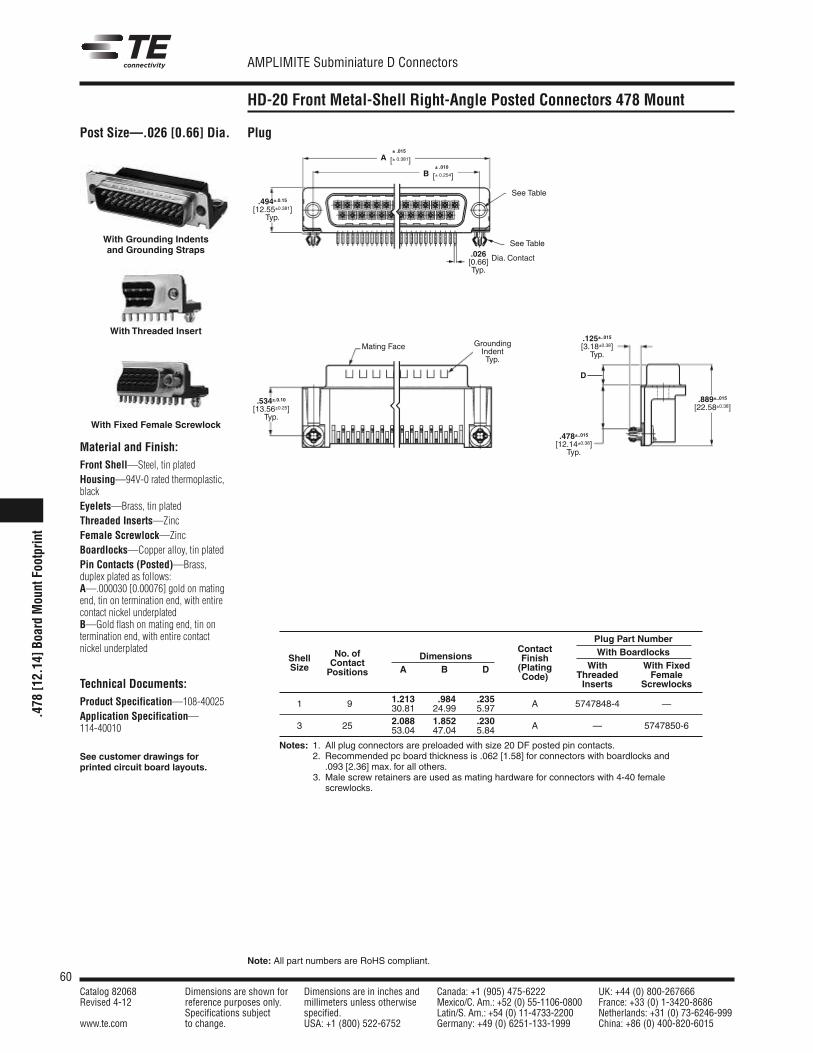
60Catalog 82068 Dimensions are shown for Dimensions are in inches and Canada: +1 (905) 475-6222 UK: +44 (0) 800-267666Revised 4-12 reference purposes only. millimeters unless otherwise Mexico/C. Am.: +52 (0) 55-1106-0800 France: +33 (0) 1-3420-8686
Specifications subject specified. Latin/S. Am.: +54 (0) 11-4733-2200 Netherlands: +31 (0) 73-6246-999www.te.com to change. USA: +1 (800) 522-6752 Germany: +49 (0) 6251-133-1999 China: +86 (0) 400-820-6015
AMPLIMITE Subminiature D Connectors
Note: All part numbers are RoHS compliant.
.478
[12.14]B
oard
MountFootprint
HD-20 Front Metal-Shell Right-Angle Posted Connectors 478 Mount
Post Size—.026 [0.66] Dia.
Material and Finish:Front Shell—Steel, tin platedHousing—94V-0 rated thermoplastic,blackEyelets—Brass, tin platedThreaded Inserts—ZincFemale Screwlock—ZincBoardlocks—Copper alloy, tin platedPin Contacts (Posted)—Brass,duplex plated as follows:A—.000030 [0.00076] gold on matingend, tin on termination end, with entirecontact nickel underplatedB—Gold flash on mating end, tin ontermination end, with entire contactnickel underplated
Technical Documents:Product Specification—108-40025Application Specification—114-40010
See customer drawings forprinted circuit board layouts.
Plug
.026[0.66] Dia. Contact
Typ.
Mating Face
See Table
See Table
GroundingIndentTyp.
D
With Grounding Indentsand Grounding Straps
With Threaded Insert
With Fixed Female Screwlock
Plug Part NumberContact With BoardlocksNo. of Finish
With With FixedShell Contact
Dimensions(Plating
Threaded FemaleSize Positions A B D
Code)Inserts Screwlocks
1.213 .984 .235 A 5747848-4 —1 9 30.81 24.99 5.972.088 1.852 .230 A — 5747850-63 25 53.04 47.04 5.84
Notes: 1. All plug connectors are preloaded with size 20 DF posted pin contacts.2. Recommended pc board thickness is .062 [1.58] for connectors with boardlocks and.093 [2.36] max. for all others.
Notes: 3. Male screw retainers are used as mating hardware for connectors with 4-40 femalescrewlocks.
.494±.0.15[12.55±0.381]
Typ.
.534±.0.10[13.56±0.25]Typ.
.125±..015[3.18±0.38]Typ.
.478±..015[12.14±0.38]Typ.
.889±..015[22.58±0.38]
A± .015
[± 0.381]
B± .010
[± 0.254]
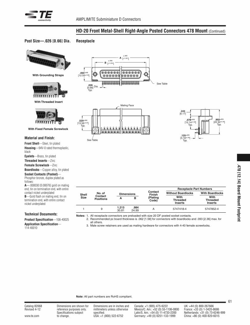
61Catalog 82068 Dimensions are shown for Dimensions are in inches and Canada: +1 (905) 475-6222 UK: +44 (0) 800-267666Revised 4-12 reference purposes only. millimeters unless otherwise Mexico/C. Am.: +52 (0) 55-1106-0800 France: +33 (0) 1-3420-8686
Specifications subject specified. Latin/S. Am.: +54 (0) 11-4733-2200 Netherlands: +31 (0) 73-6246-999www.te.com to change. USA: +1 (800) 522-6752 Germany: +49 (0) 6251-133-1999 China: +86 (0) 400-820-6015
AMPLIMITE Subminiature D Connectors
Note: All part numbers are RoHS compliant.
HD-20 Front Metal-Shell Right-Angle Posted Connectors 478 Mount (Continued)
Post Size—.026 [0.66] Dia.
Material and Finish:Front Shell—Steel, tin platedHousing—94V-0 rated thermoplastic,blackEyelets—Brass, tin platedThreaded Inserts—ZincFemale Screwlock—ZincBoardlocks—Copper alloy, tin platedSocket Contacts (Posted)—Phosphor bronze, duplex plated asfollows:A—.000030 [0.00076] gold on matingend, tin on termination end, with entirecontact nickel underplatedB—Gold flash on mating end, tin ontermination end, with entire contactnickel underplated
Technical Documents:Product Specification—108-40025Application Specification—114-40010
Receptacle
Mating Face
See Table
See Table
.494±.015[12.55±0.38]
.243[6.17]
.478±.015[12.14±0.38]Typ.
.902±.015[22.92±0.38]Typ.
.125±.015[3.18±0.38]Typ.
.026[0.66] Dia.
Typ.
.534±.010[13.56±0.25]Typ.
With Grounding Straps
With Threaded Insert
With Fixed Female Screwlock
Receptacle Part NumbersContact Without Boardlocks With BoardlocksNo. of Finish
With WithShell Contact
Dimensions(Plating
Threaded ThreadedSize Positions A B
Code)Inserts Inserts
1.213 .984 A 5747418-4 5747852-41 9 30.81 24.99
Notes: 1. All receptacle connectors are preloaded with size 20 DF posted socket contacts.2. Recommended pc board thickness is .062 [1.58] for connectors with boardlocks and .093 [2.36] max. for2. all others.3. Male screw retainers are used as mating hardware for connectors with 4-40 female screwlocks.
A± .015
[± 0.381]
B± .010
[± 0.254]
.478[12.14]Board
MountFootprint
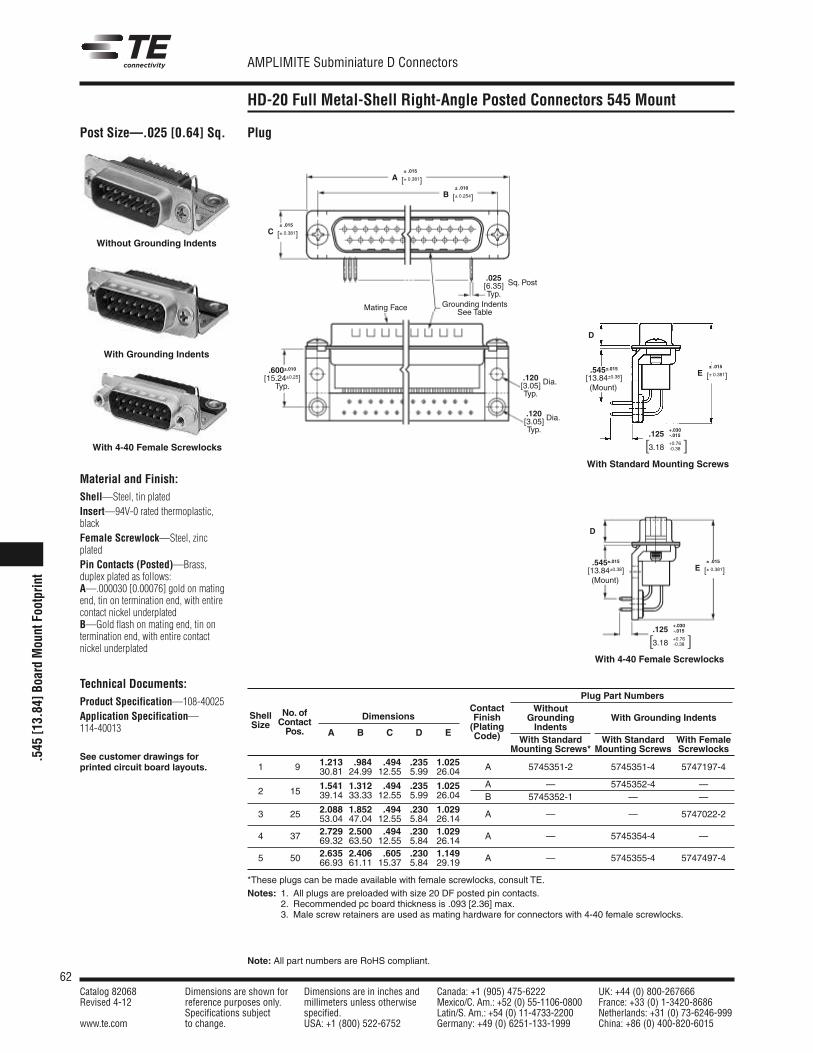
62Catalog 82068 Dimensions are shown for Dimensions are in inches and Canada: +1 (905) 475-6222 UK: +44 (0) 800-267666Revised 4-12 reference purposes only. millimeters unless otherwise Mexico/C. Am.: +52 (0) 55-1106-0800 France: +33 (0) 1-3420-8686
Specifications subject specified. Latin/S. Am.: +54 (0) 11-4733-2200 Netherlands: +31 (0) 73-6246-999www.te.com to change. USA: +1 (800) 522-6752 Germany: +49 (0) 6251-133-1999 China: +86 (0) 400-820-6015
AMPLIMITE Subminiature D Connectors
Note: All part numbers are RoHS compliant.
.545
[13.84]B
oard
MountFootprint
HD-20 Full Metal-Shell Right-Angle Posted Connectors 545 Mount
Post Size—.025 [0.64] Sq.
Material and Finish:Shell—Steel, tin platedInsert—94V-0 rated thermoplastic,blackFemale Screwlock—Steel, zincplatedPin Contacts (Posted)—Brass,duplex plated as follows:A—.000030 [0.00076] gold on matingend, tin on termination end, with entirecontact nickel underplatedB—Gold flash on mating end, tin ontermination end, with entire contactnickel underplated
Technical Documents:Product Specification—108-40025Application Specification—114-40013
See customer drawings forprinted circuit board layouts.
D
D
.120[3.05] Dia.
Typ.
.120[3.05] Dia.
Typ.
.025[6.35]Typ.
Sq. Post
Grounding IndentsSee Table
Mating Face
.600±.010[15.24±0.25]Typ.
.125+.030-.015
3.18+0.76-0.38
Plug
Without Grounding Indents
With Grounding Indents
With 4-40 Female Screwlocks
With 4-40 Female Screwlocks
With Standard Mounting Screws
Plug Part NumbersWithout
Grounding With Grounding IndentsIndents
Dimensions
With Standard With Standard With FemaleA B C D E
Mounting Screws* Mounting Screws Screwlocks1.213 .984 .494 .235 1.025 A 5745351-2 5745351-4 5747197-41 9 30.81 24.99 12.55 5.99 26.04
1.541 1.312 .494 .235 1.025 A — 5745352-4 —2 15 39.14 33.33 12.55 5.99 26.04 B 5745352-1 — —
2.088 1.852 .494 .230 1.029 A — — 5747022-23 25 53.04 47.04 12.55 5.84 26.142.729 2.500 .494 .230 1.029 A — 5745354-4 —4 37 69.32 63.50 12.55 5.84 26.142.635 2.406 .605 .230 1.149 A — 5745355-4 5747497-45 50 66.93 61.11 15.37 5.84 29.19
*These plugs can be made available with female screwlocks, consult TE.Notes: 1. All plugs are preloaded with size 20 DF posted pin contacts.
2. Recommended pc board thickness is .093 [2.36] max.3. Male screw retainers are used as mating hardware for connectors with 4-40 female screwlocks.
ContactFinish(PlatingCode)
No. ofContactPos.
ShellSize
(Mount)
.545±.015[13.84±0.38]
(Mount)
.545±.015[13.84±0.38]
[ ]
.125+.030-.015
3.18+0.76-0.38[ ]
A± .015
[± 0.381]
E± .015
[± 0.381]
E± .015
[± 0.381]
B± .010
[± 0.254]
C± .015
[± 0.381]
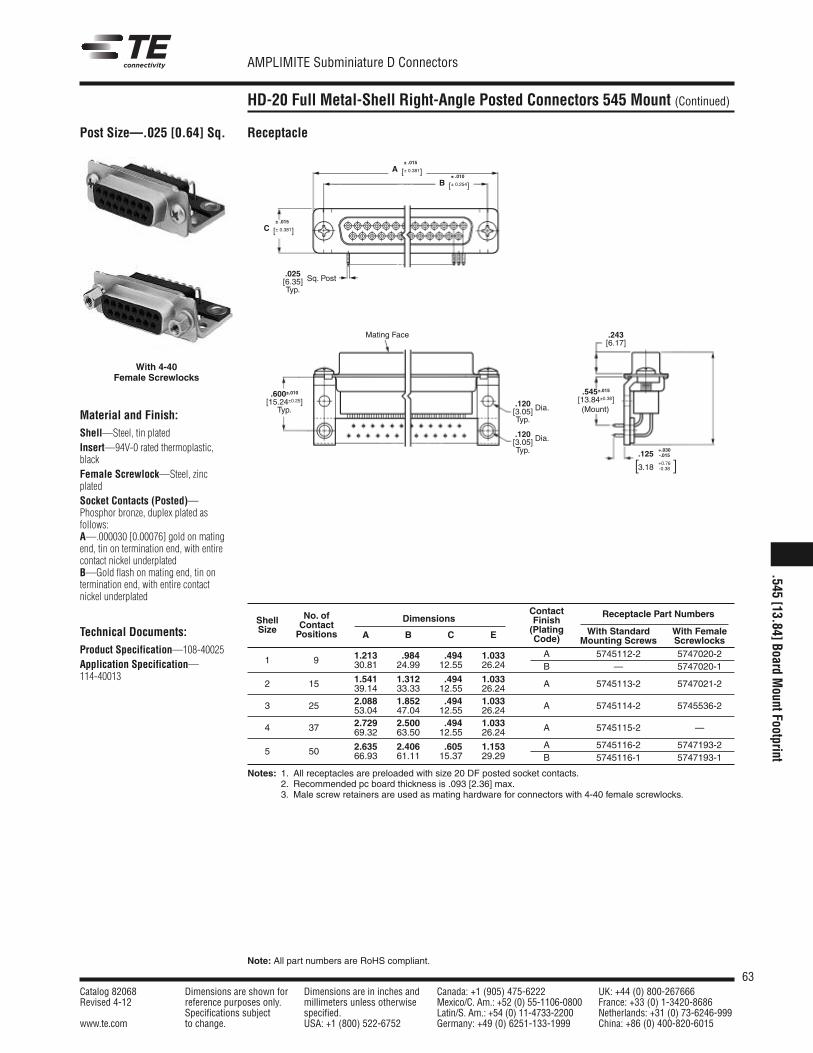
63Catalog 82068 Dimensions are shown for Dimensions are in inches and Canada: +1 (905) 475-6222 UK: +44 (0) 800-267666Revised 4-12 reference purposes only. millimeters unless otherwise Mexico/C. Am.: +52 (0) 55-1106-0800 France: +33 (0) 1-3420-8686
Specifications subject specified. Latin/S. Am.: +54 (0) 11-4733-2200 Netherlands: +31 (0) 73-6246-999www.te.com to change. USA: +1 (800) 522-6752 Germany: +49 (0) 6251-133-1999 China: +86 (0) 400-820-6015
AMPLIMITE Subminiature D Connectors
Note: All part numbers are RoHS compliant.
HD-20 Full Metal-Shell Right-Angle Posted Connectors 545 Mount (Continued)
Post Size—.025 [0.64] Sq.
Material and Finish:Shell—Steel, tin platedInsert—94V-0 rated thermoplastic,blackFemale Screwlock—Steel, zincplatedSocket Contacts (Posted)—Phosphor bronze, duplex plated asfollows:A—.000030 [0.00076] gold on matingend, tin on termination end, with entirecontact nickel underplatedB—Gold flash on mating end, tin ontermination end, with entire contactnickel underplated
Technical Documents:Product Specification—108-40025Application Specification—114-40013
Receptacle
Mating Face
(Mount)
.545±.015[13.84±0.38]
.125+.030-.015
3.18+0.76-0.38[ ]
With 4-40Female Screwlocks
ContactNo. of FinishReceptacle Part Numbers
Shell ContactDimensions
(Plating With Standard With FemaleSize Positions A B C E Code) Mounting Screws Screwlocks
1.213 .984 .494 1.033 A 5745112-2 5747020-21 9 30.81 24.99 12.55 26.24 B — 5747020-1
1.541 1.312 .494 1.033 A 5745113-2 5747021-22 15 39.14 33.33 12.55 26.242.088 1.852 .494 1.033 A 5745114-2 5745536-23 25 53.04 47.04 12.55 26.242.729 2.500 .494 1.033 A 5745115-2 —4 37 69.32 63.50 12.55 26.24
2.635 2.406 .605 1.153 A 5745116-2 5747193-25 50 66.93 61.11 15.37 29.29 B 5745116-1 5747193-1
Notes: 1. All receptacles are preloaded with size 20 DF posted socket contacts.2. Recommended pc board thickness is .093 [2.36] max.3. Male screw retainers are used as mating hardware for connectors with 4-40 female screwlocks.
.025[6.35]Typ.
.243[6.17]
Sq. Post
.600±.010[15.24±0.25]Typ.
.120[3.05] Dia.
Typ.
.120[3.05] Dia.
Typ.
A± .015
[± 0.381]B
± .010
[± 0.254]
C± .015
[± 0.381]
.545[13.84]Board
MountFootprint
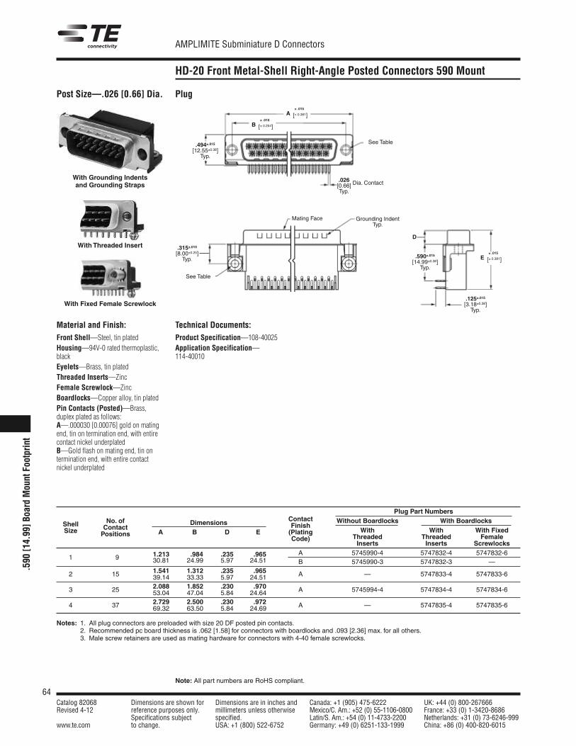
64Catalog 82068 Dimensions are shown for Dimensions are in inches and Canada: +1 (905) 475-6222 UK: +44 (0) 800-267666Revised 4-12 reference purposes only. millimeters unless otherwise Mexico/C. Am.: +52 (0) 55-1106-0800 France: +33 (0) 1-3420-8686
Specifications subject specified. Latin/S. Am.: +54 (0) 11-4733-2200 Netherlands: +31 (0) 73-6246-999www.te.com to change. USA: +1 (800) 522-6752 Germany: +49 (0) 6251-133-1999 China: +86 (0) 400-820-6015
AMPLIMITE Subminiature D Connectors
Note: All part numbers are RoHS compliant.
.590
[14.99]B
oard
MountFootprint
HD-20 Front Metal-Shell Right-Angle Posted Connectors 590 Mount
Post Size—.026 [0.66] Dia. Plug
With Grounding Indentsand Grounding Straps
With Threaded Insert
With Fixed Female Screwlock
Mating Face Grounding IndentTyp.
D
.494±.015[12.55±0.38]Typ.
.026[0.66] Dia. Contact
Typ.
.125±.015[3.18±0.38]Typ.
.590±.015[14.99±0.38]Typ.
.315±.010[8.00±0.25]Typ.
See Table
See Table
A± .015
[± 0.381]
E± .015
[± 0.381]
B± .010
[± 0.254]
Plug Part Numbers
Shell No. of Dimensions Contact Without Boardlocks With Boardlocks
Size ContactA B D E
FinishWith With With FixedPositions (Plating
Threaded Threaded FemaleCode)Inserts Inserts Screwlocks
1.213 .984 .235 .965 A 5745990-4 5747832-4 5747832-61 9 30.81 24.99 5.97 24.51 B 5745990-3 5747832-3 —
1.541 1.312 .235 .965 A — 5747833-4 5747833-62 15 39.14 33.33 5.97 24.512.088 1.852 .230 .970 A 5745994-4 5747834-4 5747834-63 25 53.04 47.04 5.84 24.642.729 2.500 .230 .972 A — 5747835-4 5747835-64 37 69.32 63.50 5.84 24.69
Notes: 1. All plug connectors are preloaded with size 20 DF posted pin contacts.2. Recommended pc board thickness is .062 [1.58] for connectors with boardlocks and .093 [2.36] max. for all others.3. Male screw retainers are used as mating hardware for connectors with 4-40 female screwlocks.
Technical Documents:Product Specification—108-40025Application Specification—114-40010
Material and Finish:Front Shell—Steel, tin platedHousing—94V-0 rated thermoplastic,blackEyelets—Brass, tin platedThreaded Inserts—ZincFemale Screwlock—ZincBoardlocks—Copper alloy, tin platedPin Contacts (Posted)—Brass,duplex plated as follows:A—.000030 [0.00076] gold on matingend, tin on termination end, with entirecontact nickel underplatedB—Gold flash on mating end, tin ontermination end, with entire contactnickel underplated
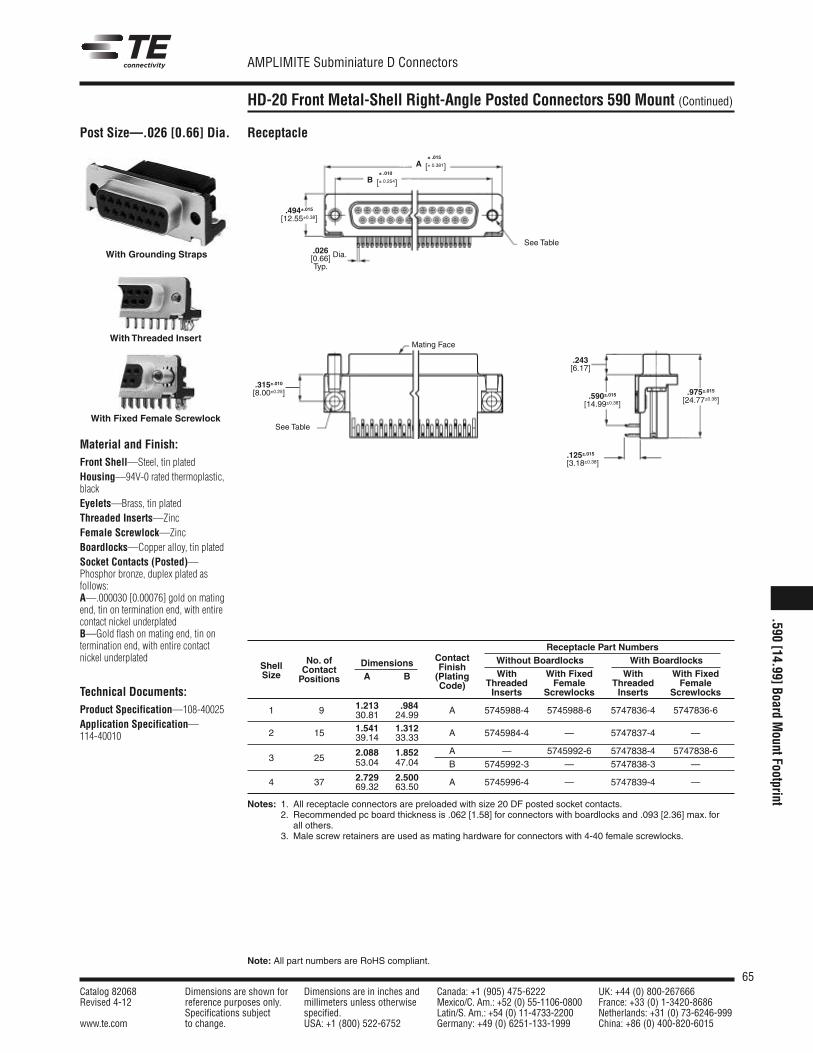
65Catalog 82068 Dimensions are shown for Dimensions are in inches and Canada: +1 (905) 475-6222 UK: +44 (0) 800-267666Revised 4-12 reference purposes only. millimeters unless otherwise Mexico/C. Am.: +52 (0) 55-1106-0800 France: +33 (0) 1-3420-8686
Specifications subject specified. Latin/S. Am.: +54 (0) 11-4733-2200 Netherlands: +31 (0) 73-6246-999www.te.com to change. USA: +1 (800) 522-6752 Germany: +49 (0) 6251-133-1999 China: +86 (0) 400-820-6015
AMPLIMITE Subminiature D Connectors
Note: All part numbers are RoHS compliant.
HD-20 Front Metal-Shell Right-Angle Posted Connectors 590 Mount (Continued)
Post Size—.026 [0.66] Dia.
Material and Finish:Front Shell—Steel, tin platedHousing—94V-0 rated thermoplastic,blackEyelets—Brass, tin platedThreaded Inserts—ZincFemale Screwlock—ZincBoardlocks—Copper alloy, tin platedSocket Contacts (Posted)—Phosphor bronze, duplex plated asfollows:A—.000030 [0.00076] gold on matingend, tin on termination end, with entirecontact nickel underplatedB—Gold flash on mating end, tin ontermination end, with entire contactnickel underplated
Technical Documents:Product Specification—108-40025Application Specification—114-40010
Receptacle
With Grounding Straps
With Threaded Insert
With Fixed Female Screwlock
Receptacle Part NumbersContact Without Boardlocks With BoardlocksNo. ofFinish
With With Fixed With With FixedShell Contact
Dimensions(Plating
Threaded Female Threaded FemaleSize Positions A B
Code)Inserts Screwlocks Inserts Screwlocks
1.213 .984 A 5745988-4 5745988-6 5747836-4 5747836-61 9 30.81 24.991.541 1.312 A 5745984-4 — 5747837-4 —2 15 39.14 33.33
2.088 1.852 A — 5745992-6 5747838-4 5747838-63 25 53.04 47.04 B 5745992-3 — 5747838-3 —
2.729 2.500 A 5745996-4 — 5747839-4 —4 37 69.32 63.50
Notes: 1. All receptacle connectors are preloaded with size 20 DF posted socket contacts.2. Recommended pc board thickness is .062 [1.58] for connectors with boardlocks and .093 [2.36] max. for2. all others.3. Male screw retainers are used as mating hardware for connectors with 4-40 female screwlocks.
.494±.015[12.55±0.38]
.243[6.17]
.590±.015[14.99±0.38]
.975±.015[24.77±0.38]
.315±.010[8.00±0.25]
.026[0.66] Dia.
Typ.
.125±.015[3.18±0.38]
Mating Face
See Table
See Table
A± .015
[± 0.381]
B± .010
[± 0.254]
.590[14.99]Board
MountFootprint
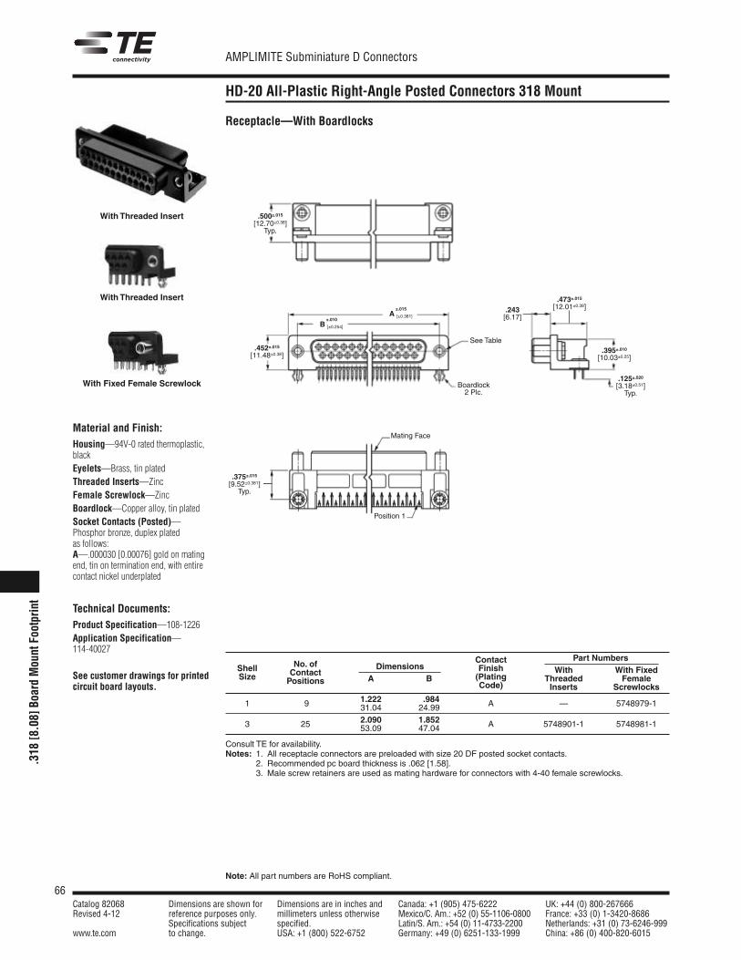
66Catalog 82068 Dimensions are shown for Dimensions are in inches and Canada: +1 (905) 475-6222 UK: +44 (0) 800-267666Revised 4-12 reference purposes only. millimeters unless otherwise Mexico/C. Am.: +52 (0) 55-1106-0800 France: +33 (0) 1-3420-8686
Specifications subject specified. Latin/S. Am.: +54 (0) 11-4733-2200 Netherlands: +31 (0) 73-6246-999www.te.com to change. USA: +1 (800) 522-6752 Germany: +49 (0) 6251-133-1999 China: +86 (0) 400-820-6015
AMPLIMITE Subminiature D Connectors
Note: All part numbers are RoHS compliant.
.318
[8.0
8]Bo
ard
Mou
ntFo
otpr
int
HD-20 All-Plastic Right-Angle Posted Connectors 318 Mount
DimensionsContact Part Numbers
Shell No. of Finish With With FixedSize Contact
A B (Plating Threaded FemalePositions Code) Inserts Screwlocks1.222 .984 A — 5748979-11 9 31.04 24.992.090 1.852 A 5748901-1 5748981-13 25 53.09 47.04
Consult TE for availability.Notes: 1. All receptacle connectors are preloaded with size 20 DF posted socket contacts.
2. Recommended pc board thickness is .062 [1.58].3. Male screw retainers are used as mating hardware for connectors with 4-40 female screwlocks.
.452±.015
[11.48±0.38]
±.015A [±0.381]
±.010B [±0.254]
.473±.015
[12.01±0.38]
.395±.010
[10.03±0.25]
.243[6.17]
.500±.015
[12.70±0.38]Typ.
.125±.020
[3.18±0.51]Typ.
Boardlock2 Plc.
See Table
Mating Face
Position 1
Material and Finish:Housing—94V-0 rated thermoplastic,blackEyelets—Brass, tin platedThreaded Inserts—ZincFemale Screwlock—ZincBoardlock—Copper alloy, tin platedSocket Contacts (Posted)—Phosphor bronze, duplex platedas follows:A—.000030 [0.00076] gold on matingend, tin on termination end, with entirecontact nickel underplated
Technical Documents:Product Specification—108-1226Application Specification—114-40027
See customer drawings for printedcircuit board layouts.
Receptacle—With Boardlocks
With Threaded Insert
With Threaded Insert
With Fixed Female Screwlock
.375±.015
[9.52±0.381]Typ.
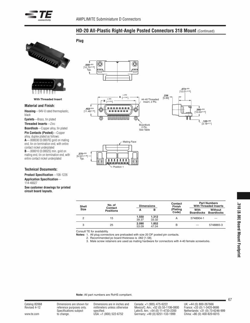
67Catalog 82068 Dimensions are shown for Dimensions are in inches and Canada: +1 (905) 475-6222 UK: +44 (0) 800-267666Revised 4-12 reference purposes only. millimeters unless otherwise Mexico/C. Am.: +52 (0) 55-1106-0800 France: +33 (0) 1-3420-8686
Specifications subject specified. Latin/S. Am.: +54 (0) 11-4733-2200 Netherlands: +31 (0) 73-6246-999www.te.com to change. USA: +1 (800) 522-6752 Germany: +49 (0) 6251-133-1999 China: +86 (0) 400-820-6015
AMPLIMITE Subminiature D Connectors
Note: All part numbers are RoHS compliant.
HD-20 All-Plastic Right-Angle Posted Connectors 318 Mount (Continued)
Plug
Material and Finish:Housing—94V-0 rated thermoplastic,blackEyelets—Brass, tin platedThreaded Inserts—ZincBoardlock—Copper alloy, tin platedPin Contacts (Posted)—Copperalloy, duplex plated as follows:A—.000030 [0.00076] gold on matingend, tin on termination end, with entirecontact nickel underplatedB—.000010 [0.00025] min. gold onmating end, tin on termination end, withentire contact nickel underplated
Technical Documents:Product Specification—108-1226Application Specification—114-40027See customer drawings for printedcircuit board layouts.
Contact Part NumbersNo. of Finish With Threaded InsertsShell Contact
Dimensions(Plating With WithoutSize Positions A BCode) Boardlocks Boardlocks
1.550 1.3122 15 39.37 33.32 A 5748904-1 —
2.090 1.8523 25 53.09 47.04 B — 5748865-3
Consult TE for availability.Notes: 1. All plug connectors are preloaded with size 20 DF posted pin contacts.
2. Recommended pc board thickness is .062 [1.58].3. Male screw retainers are used as mating hardware for connectors with 4-40 female screwlocks.
.452±.015
[11.48±0.38]
.473±.015
[12.01±0.38]
.395±.010
[10.03±0.25]
.125±.020
[3.18±0.51]
.236[5.99]
.500±.015
[12.70±0.38]Typ.
#4-40 ThreadedInsert, 2 Plc.
Mating Face
Position 1
With Threaded InsertA
± .015
[± 0.381]B
± .010
[± 0.254]
.375±.015
[9.521±0.38]Typ.
Boardlock2 Plc.
See Table
.318[8.08]Board
MountFootprint
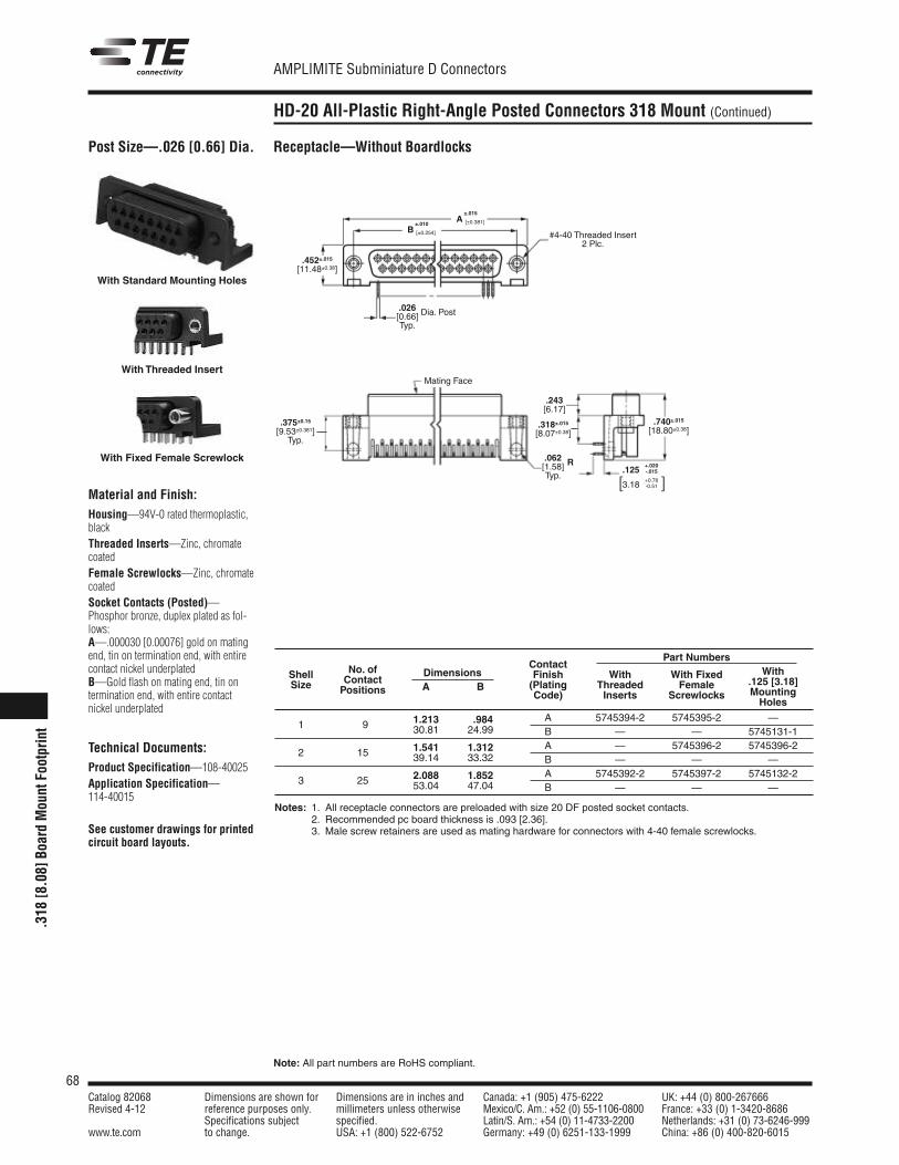
68Catalog 82068 Dimensions are shown for Dimensions are in inches and Canada: +1 (905) 475-6222 UK: +44 (0) 800-267666Revised 4-12 reference purposes only. millimeters unless otherwise Mexico/C. Am.: +52 (0) 55-1106-0800 France: +33 (0) 1-3420-8686
Specifications subject specified. Latin/S. Am.: +54 (0) 11-4733-2200 Netherlands: +31 (0) 73-6246-999www.te.com to change. USA: +1 (800) 522-6752 Germany: +49 (0) 6251-133-1999 China: +86 (0) 400-820-6015
AMPLIMITE Subminiature D Connectors
Note: All part numbers are RoHS compliant.
HD-20 All-Plastic Right-Angle Posted Connectors 318 Mount (Continued)
Post Size—.026 [0.66] Dia.
Material and Finish:Housing—94V-0 rated thermoplastic,blackThreaded Inserts—Zinc, chromatecoatedFemale Screwlocks—Zinc, chromatecoatedSocket Contacts (Posted)—Phosphor bronze, duplex plated as fol-lows:A—.000030 [0.00076] gold on matingend, tin on termination end, with entirecontact nickel underplatedB—Gold flash on mating end, tin ontermination end, with entire contactnickel underplated
Technical Documents:Product Specification—108-40025Application Specification—114-40015
See customer drawings for printedcircuit board layouts.
Receptacle—Without Boardlocks
Notes: 1. All receptacle connectors are preloaded with size 20 DF posted socket contacts.2. Recommended pc board thickness is .093 [2.36].3. Male screw retainers are used as mating hardware for connectors with 4-40 female screwlocks.
Part NumbersContact
WithNo. of Finish With With Fixed.125 [3.18]
Shell ContactDimensions
(Plating Threaded FemaleMounting
Size Positions A BCode) Inserts Screwlocks
Holes
1.213 .984 A 5745394-2 5745395-2 —1 9 30.81 24.99 B — — 5745131-1
1.541 1.312 A — 5745396-2 5745396-22 15 39.14 33.32 B — — —
2.088 1.852 A 5745392-2 5745397-2 5745132-23 25 53.04 47.04 B — — —
With Standard Mounting Holes
With Threaded Insert
With Fixed Female Screwlock
.452±.015
[11.48±0.38]
.375±0.15
[9.53±0.381]Typ.
.243[6.17]
.318±.015
[8.07±0.38].740±.015
[18.80±0.38]
.026[0.66] Dia. Post
Typ.
.062[1.58] R
Typ.
#4-40 Threaded Insert2 Plc.
Mating Face
.125+.020-.015
3.18+0.76-0.51[ ]
±.015A [±0.381]±.010
B [±0.254]
.318
[8.0
8]Bo
ard
Mou
ntFo
otpr
int
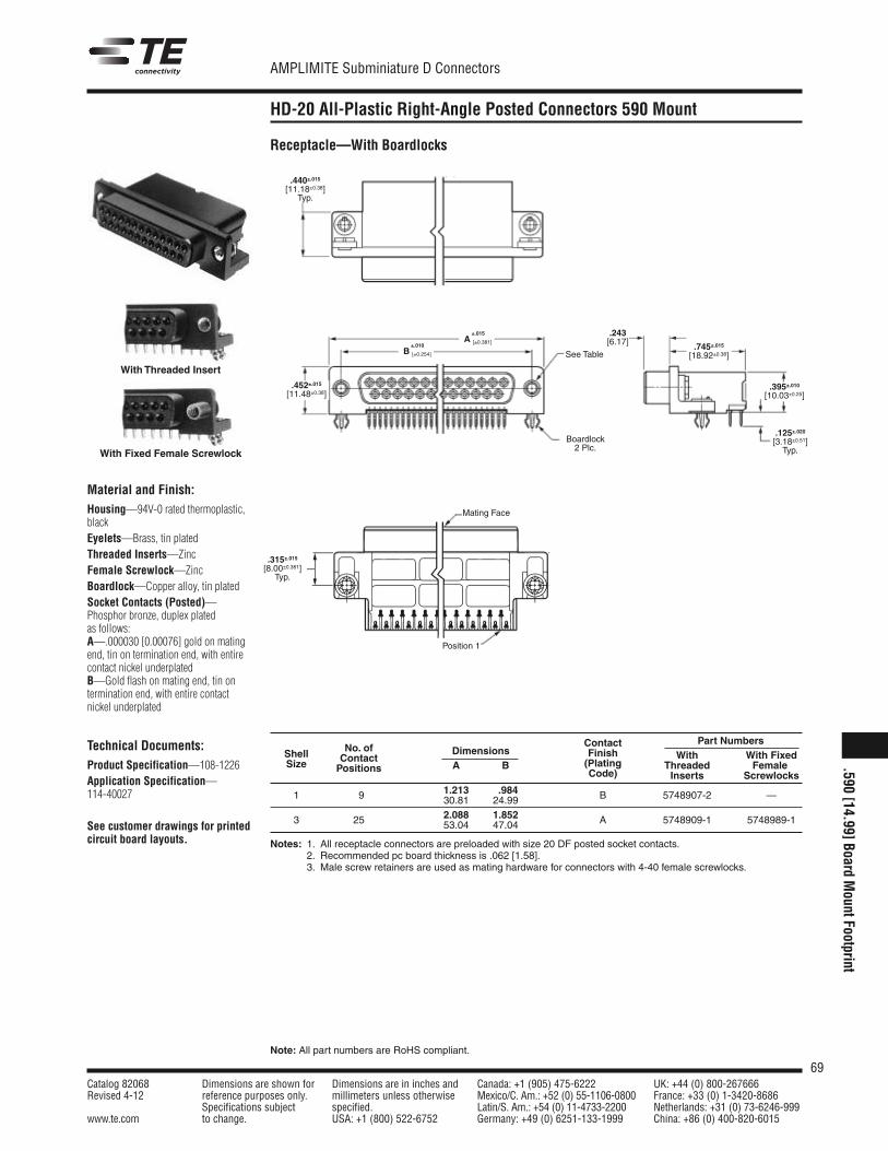
69Catalog 82068 Dimensions are shown for Dimensions are in inches and Canada: +1 (905) 475-6222 UK: +44 (0) 800-267666Revised 4-12 reference purposes only. millimeters unless otherwise Mexico/C. Am.: +52 (0) 55-1106-0800 France: +33 (0) 1-3420-8686
Specifications subject specified. Latin/S. Am.: +54 (0) 11-4733-2200 Netherlands: +31 (0) 73-6246-999www.te.com to change. USA: +1 (800) 522-6752 Germany: +49 (0) 6251-133-1999 China: +86 (0) 400-820-6015
AMPLIMITE Subminiature D Connectors
Note: All part numbers are RoHS compliant.
HD-20 All-Plastic Right-Angle Posted Connectors 590 Mount
With Threaded Insert
With Fixed Female Screwlock
.243[6.17]
.452±.015
[11.48±0.38]
.745±.015
[18.92±0.38]
.395±.010
[10.03±0.25]
.440±.015
[11.18±0.38]Typ.
.125±.020
[3.18±0.51]Typ.
.315±.015
[8.00±0.381]Typ.
See Table
Boardlock2 Plc.
Mating Face
Position 1
Material and Finish:Housing—94V-0 rated thermoplastic,blackEyelets—Brass, tin platedThreaded Inserts—ZincFemale Screwlock—ZincBoardlock—Copper alloy, tin platedSocket Contacts (Posted)—Phosphor bronze, duplex platedas follows:A—.000030 [0.00076] gold on matingend, tin on termination end, with entirecontact nickel underplatedB—Gold flash on mating end, tin ontermination end, with entire contactnickel underplated
Technical Documents:Product Specification—108-1226Application Specification—114-40027
See customer drawings for printedcircuit board layouts.
Receptacle—With Boardlocks
Contact Part NumbersNo. of Finish With With FixedShell Contact
Dimensions(Plating Threaded FemaleSize Positions A BCode) Inserts Screwlocks
1.213 .9841 9 30.81 24.99 B 5748907-2 —
2.088 1.852 A 5748909-1 5748989-13 25 53.04 47.04
Notes: 1. All receptacle connectors are preloaded with size 20 DF posted socket contacts.2. Recommended pc board thickness is .062 [1.58].3. Male screw retainers are used as mating hardware for connectors with 4-40 female screwlocks.
±.015A [±0.381]
±.010B [±0.254]
.590[14.99]Board
MountFootprint
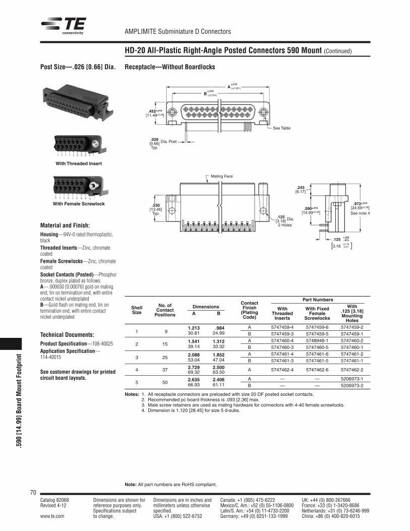
70Catalog 82068 Dimensions are shown for Dimensions are in inches and Canada: +1 (905) 475-6222 UK: +44 (0) 800-267666Revised 4-12 reference purposes only. millimeters unless otherwise Mexico/C. Am.: +52 (0) 55-1106-0800 France: +33 (0) 1-3420-8686
Specifications subject specified. Latin/S. Am.: +54 (0) 11-4733-2200 Netherlands: +31 (0) 73-6246-999www.te.com to change. USA: +1 (800) 522-6752 Germany: +49 (0) 6251-133-1999 China: +86 (0) 400-820-6015
AMPLIMITE Subminiature D Connectors
Note: All part numbers are RoHS compliant.
.590
[14.
99]B
oard
Mou
ntFo
otpr
int
HD-20 All-Plastic Right-Angle Posted Connectors 590 Mount (Continued)
Post Size—.026 [0.66] Dia.
Material and Finish:Housing—94V-0 rated thermoplastic,blackThreaded Inserts—Zinc, chromatecoatedFemale Screwlocks—Zinc, chromatecoatedSocket Contacts (Posted)—Phosphorbronze, duplex plated as follows:A—.000030 [0.00076] gold on matingend, tin on termination end, with entirecontact nickel underplatedB—Gold flash on mating end, tin ontermination end, with entire contactnickel underplated
Technical Documents:Product Specification—108-40025Application Specification—114-40015
See customer drawings for printedcircuit board layouts.
Receptacle—Without Boardlocks
Part NumbersContact
WithNo. of Finish With With Fixed .125 [3.18]Shell Contact
Dimensions(Plating Threaded Female Mounting
Size Positions A BCode) Inserts Screwlocks Holes
1.213 .984 A 5747459-4 5747459-6 5747459-21 9 30.81 24.99 B 5747459-3 5747459-5 5747459-1
1.541 1.312 A 5747460-4 5748948-1 5747460-22 15 39.14 33.32 B 5747460-3 5747460-5 5747460-1
2.088 1.852 A 5747461-4 5747461-6 5747461-23 25 53.04 47.04 B 5747461-3 5747461-5 5747461-1
2.729 2.500 A 5747462-4 5747462-6 5747462-24 37 69.32 63.50
2.635 2.406 A — — 5206973-15 50 66.93 61.11 B — — 5206973-2
Notes: 1. All receptacle connectors are preloaded with size 20 DF posted socket contacts.2. Recommended pc board thickness is .093 [2.36] max.3. Male screw retainers are used as mating hardware for connectors with 4-40 female screwlocks.4. Dimension is 1.120 [28.45] for size 5 d-subs.
With Threaded Insert
With Female Screwlock
.452±.015
[11.48±0.38]
.530[13.46]Typ.
.243[6.17]
.590±.015
[14.99±0.38]
.972±.015
[24.69±0.38]See note 4
.026[0.66] Dia. Post
Typ.
.125[3.18] Dia.
2 Holes
Mating Face
See Table
.125+.020-.015
3.18+0.76-0.51[ ]
±.015A [±0.381]
±.010B [±0.254]
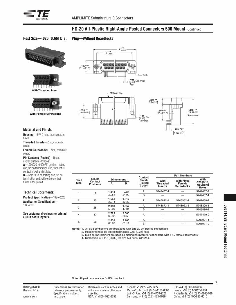
71Catalog 82068 Dimensions are shown for Dimensions are in inches and Canada: +1 (905) 475-6222 UK: +44 (0) 800-267666Revised 4-12 reference purposes only. millimeters unless otherwise Mexico/C. Am.: +52 (0) 55-1106-0800 France: +33 (0) 1-3420-8686
Specifications subject specified. Latin/S. Am.: +54 (0) 11-4733-2200 Netherlands: +31 (0) 73-6246-999www.te.com to change. USA: +1 (800) 522-6752 Germany: +49 (0) 6251-133-1999 China: +86 (0) 400-820-6015
AMPLIMITE Subminiature D Connectors
Note: All part numbers are RoHS compliant.
HD-20 All-Plastic Right-Angle Posted Connectors 590 Mount (Continued)
Post Size—.026 [0.66] Dia.
Material and Finish:Housing—94V-0 rated thermoplastic,blackThreaded Inserts—Zinc, chromatecoatedFemale Screwlocks—Zinc, chromatecoatedPin Contacts (Posted)—Brass,duplex plated as follows:A—.000030 [0.00076] gold on matingend, tin on termination end, with entirecontact nickel underplatedB—Gold flash on mating end, tin ontermination end, with entire contactnickel underplated
Technical Documents:Product Specification—108-40025Application Specification—114-40015
See customer drawings for printedcircuit board layouts.
Part NumbersContact
WithNo. of Finish With With Fixed .125 [3.18]Shell Contact
Dimensions(Plating Threaded Female Mounting
Size Positions A BCode) Inserts Screwlocks Holes
1.213 .984 A 5747467-4 — 5747467-21 9 30.81 24.99 B — — 5747467-1
1.541 1.312 A 5748872-1 5748952-1 5747468-22 15 39.14 33.32
2.090 1.852 A 5748873-1 5748953-1 5748826-13 25 53.09 47.04 B — — 5748826-2
2.729 2.500 A — — 5747470-24 37 69.32 63.50
2.635 2.406 A — — 5206971-15 50 66.93 61.11 B — — 5206971-2
Notes: 1. All plug connectors are preloaded with size 20 DF posted pin contacts.2. Recommended pc board thickness is .093 [2.36] max.3. Male screw retainers are used as mating hardware for connectors with 4-40 female screwlocks.4. Dimension is 1.115 [28.32] for size 5 d-subs, GPL244.
Plug—Without Boardlocks
With Threaded Insert
With Female Screwlocks
.452±.015
[11.48±0.38]
.530±.015
[13.46±0.381]
.230±.006
[5.84±0.15]
.590±.015
[14.99±0.38].968±.015
[24.59±0.38]See note 4
.026[0.66] Dia. Post
Typ.
Mating Face
See Table
.125[3.18] Dia.
2 Holes
.125+.020-.015
3.18+0.76-0.51[ ]
±.015A [±0.381]
±.010B [±0.254]
.590[14.99]Board
MountFootprint
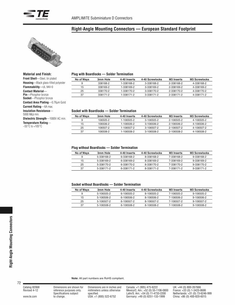
72Catalog 82068 Dimensions are shown for Dimensions are in inches and Canada: +1 (905) 475-6222 UK: +44 (0) 800-267666Revised 4-12 reference purposes only. millimeters unless otherwise Mexico/C. Am.: +52 (0) 55-1106-0800 France: +33 (0) 1-3420-8686
Specifications subject specified. Latin/S. Am.: +54 (0) 11-4733-2200 Netherlands: +31 (0) 73-6246-999www.te.com to change. USA: +1 (800) 522-6752 Germany: +49 (0) 6251-133-1999 China: +86 (0) 400-820-6015
AMPLIMITE Subminiature D Connectors
Note: All part numbers are RoHS compliant.
Rig
ht-A
ngle
Mou
ntin
gCo
nnec
tors
Right-Angle Mounting Connectors — European Standard Footprint
Material and Finish:Front Shell—Steel, tin platedHousing—Black glass-filled polyesterFlammability—UL 94V-0Contact Material—Pin—Phosphor bronzeSocket—Phosphor bronzeContact Area Plating—0.76µm GoldCurrent Rating—6A max.Insulation Resistance—5000 MΩ min.Dielectric Strength—1000V AC min.Temperature Rating—–55°C to +105°C
Plug with Boardlocks — Solder TerminationNo ofWays 3mm Hole 4-40 Inserts 4-40 Screwlocks M3 Inserts M3 Screwlocks
9 338168-2 1-338168-2 3-338168-2 2-338168-2 4-338168-215 338169-2 1-338169-2 3-338169-2 2-338169-2 4-338169-225 338170-2 1-338170-2 3-338170-2 2-338170-2 4-338170-237 338171-2 1-338171-2 3-338171-2 2-338171-2 4-338171-2
Socket with Boardlocks — Solder TerminationNo ofWays 3mm Hole 4-40 Inserts 4-40 Screwlocks M3 Inserts M3 Screwlocks
9 106505-2 1-106505-2 3-106505-2 2-106505-2 4-106505-215 106506-2 1-106506-2 3-106506-2 2-106506-2 4-106506-225 106507-2 1-106507-2 3-106507-2 2-106507-2 4-106507-237 106508-2 1-106508-2 3-106508-2 2-106508-2 4-106508-2
Plug without Boardlocks — Solder TerminationNo ofWays 3mm Hole 4-40 Inserts 4-40 Screwlocks M3 Inserts M3 Screwlocks
9 5-338168-2 6-338168-2 8-338168-2 7-338168-2 9-338168-215 5-338169-2 6-338169-2 8-338169-2 7-338169-2 9-338169-225 5-338170-2 6-338170-2 8-338170-2 7-338170-2 9-338170-237 5-338171-2 6-338171-2 8-338171-2 7-338171-2 9-338171-2
Socket without Boardlocks — Solder TerminationNo ofWays 3mm Hole 4-40 Inserts 4-40 Screwlocks M3 Inserts M3 Screwlocks
9 5-106505-2 6-106505-2 8-106505-2 7-106505-2 9-106505-215 5-106506-2 6-106506-2 8-106506-2 7-106506-2 9-106506-225 5-106507-2 6-106507-2 8-106507-2 7-106507-2 9-106507-237 5-106508-2 6-106508-2 8-106508-2 7-106508-2 9-106508-2
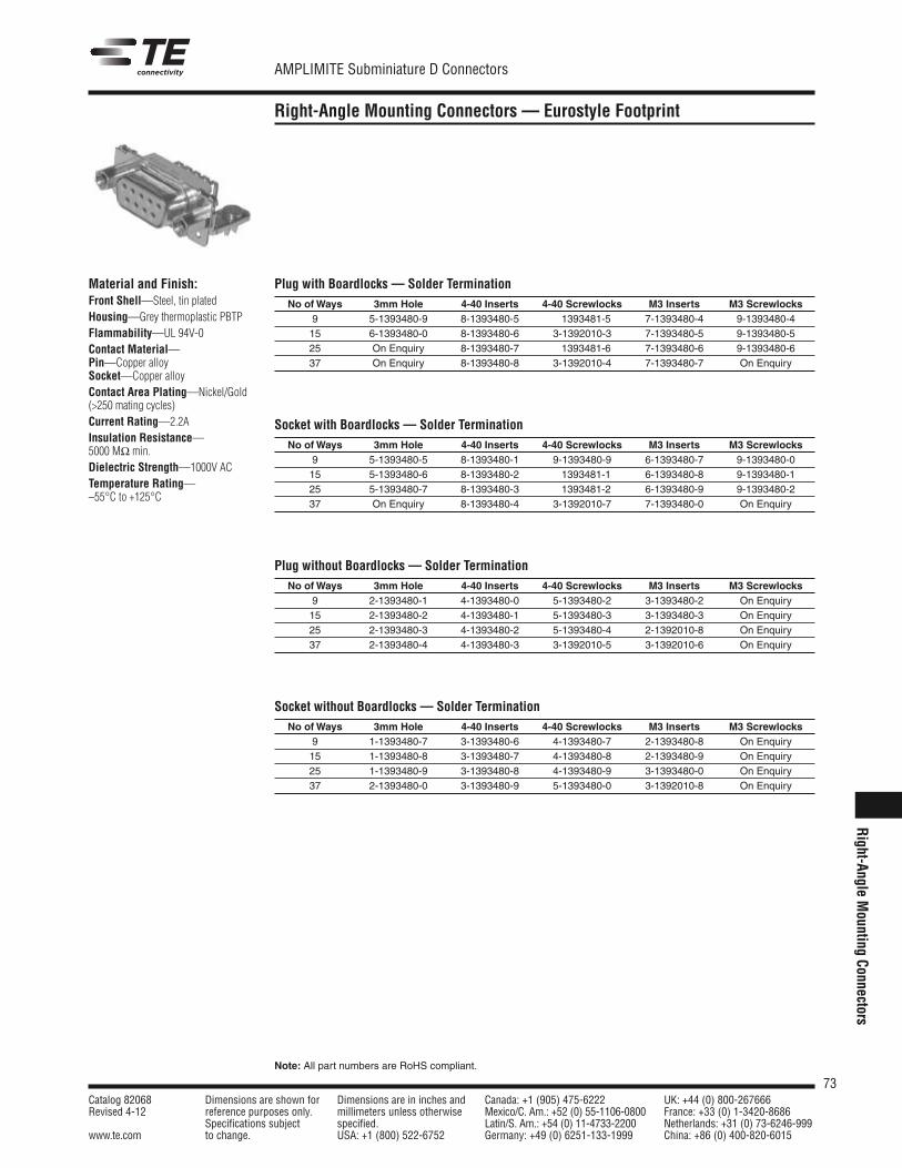
73Catalog 82068 Dimensions are shown for Dimensions are in inches and Canada: +1 (905) 475-6222 UK: +44 (0) 800-267666Revised 4-12 reference purposes only. millimeters unless otherwise Mexico/C. Am.: +52 (0) 55-1106-0800 France: +33 (0) 1-3420-8686
Specifications subject specified. Latin/S. Am.: +54 (0) 11-4733-2200 Netherlands: +31 (0) 73-6246-999www.te.com to change. USA: +1 (800) 522-6752 Germany: +49 (0) 6251-133-1999 China: +86 (0) 400-820-6015
AMPLIMITE Subminiature D Connectors
Note: All part numbers are RoHS compliant.
Right-Angle Mounting Connectors — Eurostyle Footprint
Material and Finish:Front Shell—Steel, tin platedHousing—Grey thermoplastic PBTPFlammability—UL 94V-0Contact Material—Pin—Copper alloySocket—Copper alloyContact Area Plating—Nickel/Gold(>250 mating cycles)Current Rating—2.2AInsulation Resistance—5000 MΩ min.Dielectric Strength—1000V ACTemperature Rating—–55°C to +125°C
Plug with Boardlocks — Solder TerminationNo ofWays 3mm Hole 4-40 Inserts 4-40 Screwlocks M3 Inserts M3 Screwlocks
9 5-1393480-9 8-1393480-5 1393481-5 7-1393480-4 9-1393480-415 6-1393480-0 8-1393480-6 3-1392010-3 7-1393480-5 9-1393480-525 On Enquiry 8-1393480-7 1393481-6 7-1393480-6 9-1393480-637 On Enquiry 8-1393480-8 3-1392010-4 7-1393480-7 On Enquiry
Socket with Boardlocks — Solder TerminationNo ofWays 3mm Hole 4-40 Inserts 4-40 Screwlocks M3 Inserts M3 Screwlocks
9 5-1393480-5 8-1393480-1 9-1393480-9 6-1393480-7 9-1393480-015 5-1393480-6 8-1393480-2 1393481-1 6-1393480-8 9-1393480-125 5-1393480-7 8-1393480-3 1393481-2 6-1393480-9 9-1393480-237 On Enquiry 8-1393480-4 3-1392010-7 7-1393480-0 On Enquiry
Plug without Boardlocks — Solder TerminationNo ofWays 3mm Hole 4-40 Inserts 4-40 Screwlocks M3 Inserts M3 Screwlocks
9 2-1393480-1 4-1393480-0 5-1393480-2 3-1393480-2 On Enquiry15 2-1393480-2 4-1393480-1 5-1393480-3 3-1393480-3 On Enquiry25 2-1393480-3 4-1393480-2 5-1393480-4 2-1392010-8 On Enquiry37 2-1393480-4 4-1393480-3 3-1392010-5 3-1392010-6 On Enquiry
Socket without Boardlocks — Solder TerminationNo ofWays 3mm Hole 4-40 Inserts 4-40 Screwlocks M3 Inserts M3 Screwlocks
9 1-1393480-7 3-1393480-6 4-1393480-7 2-1393480-8 On Enquiry15 1-1393480-8 3-1393480-7 4-1393480-8 2-1393480-9 On Enquiry25 1-1393480-9 3-1393480-8 4-1393480-9 3-1393480-0 On Enquiry37 2-1393480-0 3-1393480-9 5-1393480-0 3-1392010-8 On Enquiry
Right-Angle
Mounting
Connectors
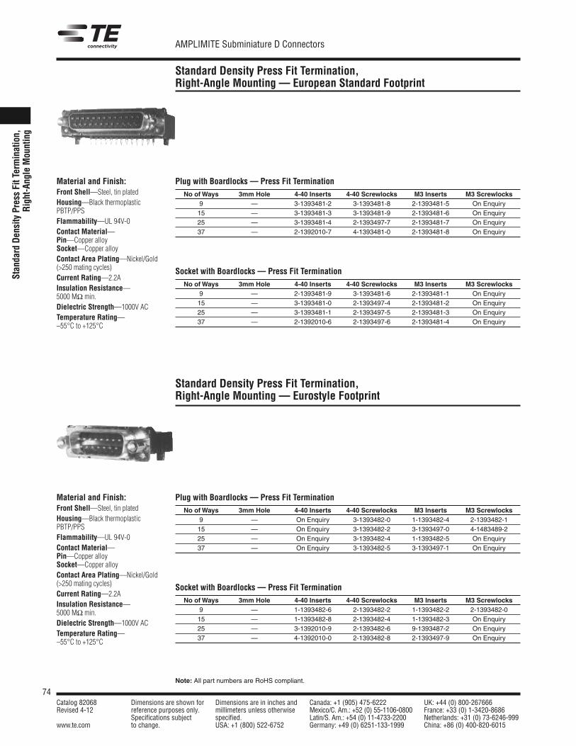
74Catalog 82068 Dimensions are shown for Dimensions are in inches and Canada: +1 (905) 475-6222 UK: +44 (0) 800-267666Revised 4-12 reference purposes only. millimeters unless otherwise Mexico/C. Am.: +52 (0) 55-1106-0800 France: +33 (0) 1-3420-8686
Specifications subject specified. Latin/S. Am.: +54 (0) 11-4733-2200 Netherlands: +31 (0) 73-6246-999www.te.com to change. USA: +1 (800) 522-6752 Germany: +49 (0) 6251-133-1999 China: +86 (0) 400-820-6015
AMPLIMITE Subminiature D Connectors
Note: All part numbers are RoHS compliant.
Stan
dard
Den
sity
Pres
sFi
tTer
min
atio
n,R
ight
-Ang
leM
ount
ing
Standard Density Press Fit Termination,Right-Angle Mounting — European Standard Footprint
Material and Finish:Front Shell—Steel, tin platedHousing—Black thermoplasticPBTP/PPSFlammability—UL 94V-0Contact Material—Pin—Copper alloySocket—Copper alloyContact Area Plating—Nickel/Gold(>250 mating cycles)Current Rating—2.2AInsulation Resistance—5000 MΩ min.Dielectric Strength—1000V ACTemperature Rating—–55°C to +125°C
Plug with Boardlocks — Press Fit TerminationNo ofWays 3mm Hole 4-40 Inserts 4-40 Screwlocks M3 Inserts M3 Screwlocks
9 — 3-1393481-2 3-1393481-8 2-1393481-5 On Enquiry15 — 3-1393481-3 3-1393481-9 2-1393481-6 On Enquiry25 — 3-1393481-4 2-1393497-7 2-1393481-7 On Enquiry37 — 2-1392010-7 4-1393481-0 2-1393481-8 On Enquiry
Socket with Boardlocks — Press Fit TerminationNo ofWays 3mm Hole 4-40 Inserts 4-40 Screwlocks M3 Inserts M3 Screwlocks
9 — 2-1393481-9 3-1393481-6 2-1393481-1 On Enquiry15 — 3-1393481-0 2-1393497-4 2-1393481-2 On Enquiry25 — 3-1393481-1 2-1393497-5 2-1393481-3 On Enquiry37 — 2-1392010-6 2-1393497-6 2-1393481-4 On Enquiry
Standard Density Press Fit Termination,Right-Angle Mounting — Eurostyle Footprint
Material and Finish:Front Shell—Steel, tin platedHousing—Black thermoplasticPBTP/PPSFlammability—UL 94V-0Contact Material—Pin—Copper alloySocket—Copper alloyContact Area Plating—Nickel/Gold(>250 mating cycles)Current Rating—2.2AInsulation Resistance—5000 MΩ min.Dielectric Strength—1000V ACTemperature Rating—–55°C to +125°C
Plug with Boardlocks — Press Fit TerminationNo ofWays 3mm Hole 4-40 Inserts 4-40 Screwlocks M3 Inserts M3 Screwlocks
9 — On Enquiry 3-1393482-0 1-1393482-4 2-1393482-115 — On Enquiry 3-1393482-2 3-1393497-0 4-1483489-225 — On Enquiry 3-1393482-4 1-1393482-5 On Enquiry37 — On Enquiry 3-1393482-5 3-1393497-1 On Enquiry
Socket with Boardlocks — Press Fit TerminationNo ofWays 3mm Hole 4-40 Inserts 4-40 Screwlocks M3 Inserts M3 Screwlocks
9 — 1-1393482-6 2-1393482-2 1-1393482-2 2-1393482-015 — 1-1393482-8 2-1393482-4 1-1393482-3 On Enquiry25 — 3-1392010-9 2-1393482-6 9-1393487-2 On Enquiry37 — 4-1392010-0 2-1393482-8 2-1393497-9 On Enquiry
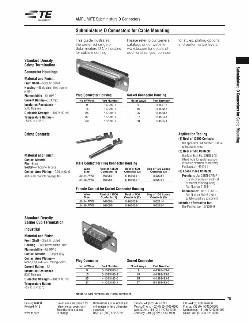
75Catalog 82068 Dimensions are shown for Dimensions are in inches and Canada: +1 (905) 475-6222 UK: +44 (0) 800-267666Revised 4-12 reference purposes only. millimeters unless otherwise Mexico/C. Am.: +52 (0) 55-1106-0800 France: +33 (0) 1-3420-8686
Specifications subject specified. Latin/S. Am.: +54 (0) 11-4733-2200 Netherlands: +31 (0) 73-6246-999www.te.com to change. USA: +1 (800) 522-6752 Germany: +49 (0) 6251-133-1999 China: +86 (0) 400-820-6015
AMPLIMITE Subminiature D Connectors
Note: All part numbers are RoHS compliant.
Subminiature D Connectors for Cable Mounting
This guide illustratesthe preferred range ofSubminiature D Connectorsfor cable mounting.
Please refer to our generalcatalogs or our websitewww.te.com for details ofadditional ranges, connec-
tor styles, plating optionsand performance levels.
Standard DensityCrimp Termination
Connector Housings
Material and Finish:Front Shell—Steel, tin platedHousing—Black glass-filled thermo-plasticFlammability—UL 94V-0Current Rating—3.7A max.Insulation Resistance—5000 MΩ min.Dielectric Strength—1000V AC min.Temperature Rating—–55°C to +105°C
Plug Connector HousingNo ofWays Part Number
9 167292-115 167293-125 167294-137 167295-150 167296-1
Socket Connector HousingNo ofWays Part Number
9 164531-415 164532-425 164533-437 164534-450 164535-4
Crimp Contacts
Material and Finish:Contact Material—Pin—BrassSocket—Phosphor bronzeContact Area Plating—0.76µm GoldAdditional contacts on page 105
Male Contact for Plug Connector HousingWire Reel of 12500 Reel of 500 Bag of 100 LooseSize Contacts (1) Contacts (2) Contacts (3)
20-24 AWG 166053-1 5-166053-1 166293-124-28 AWG 166054-1 5-166054-1 166294-1
Female Contact for Socket Connector HousingWire Reel of 12500 Reel of 500 Bag of 100 LooseSize Contacts (1) Contacts (2) Contacts (3)
20-24 AWG 166051-1 5-166051-1 166291-124-28 AWG 166052-1 5-166052-1 166292-1
Application Tooling(1) Reel of 12500 Contacts
Use applicator Part Number 1238049with suitable press.
(2) Reel of 500 ContactsUse Mini Reel-Fed CERTI-LOK(Hand tools for applying and/orextracting electrical connectors)Part Number 169424-1
(3) Loose Piece ContactsPremium: Use CERTI-CRIMP II
(Hand compression electricalconnector crimping tools) —Part Number 91503-1
Commercial: Use SDE die —Part Number 58448-2 withsuitable ancillary equipment
Insertion / Extraction ToolUse Part Number 1579007-9
Standard DensitySolder Cup Termination
Industrial
Material and Finish:Front Shell—Steel, tin platedHousing—Grey thermoplastic PBTPFlammability—UL 94V-0Contact Material—Copper alloyContact Area Plating—Nickel/Pd/Gold (>250 mating cycles)Current Rating—3AInsulation Resistance—5000 MΩ min.Dielectric Strength—1000V AC min.Temperature Rating—–55°C to +125°C
Plug ConnectorNo ofWays Part Number
9 3-1393483-815 3-1393483-925 4-1393483-037 4-1393483-1
Socket ConnectorNo ofWays Part Number
9 4-1393483-715 4-1393483-825 4-1393483-937 5-1393483-0
Subminiature
DConnectors
forCableM
ounting
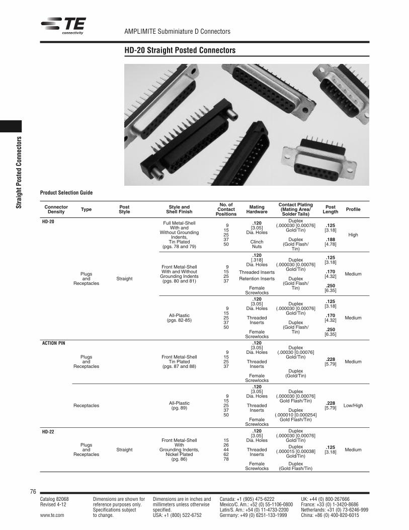
76Catalog 82068 Dimensions are shown for Dimensions are in inches and Canada: +1 (905) 475-6222 UK: +44 (0) 800-267666Revised 4-12 reference purposes only. millimeters unless otherwise Mexico/C. Am.: +52 (0) 55-1106-0800 France: +33 (0) 1-3420-8686
Specifications subject specified. Latin/S. Am.: +54 (0) 11-4733-2200 Netherlands: +31 (0) 73-6246-999www.te.com to change. USA: +1 (800) 522-6752 Germany: +49 (0) 6251-133-1999 China: +86 (0) 400-820-6015
AMPLIMITE Subminiature D Connectors
StraightPo
sted
Connectors
HD-20 Straight Posted Connectors
No. of Contact PlatingConnector Post Style and Contact Mating (Mating Area/ PostDensity Type Style Shell Finish Positions Hardware Solder Tails) Length Profile
DuplexFull Metal-Shell 9 .120 (.000030 [0.00076] .125With and 15 [3.05] Gold/Tin) [3.18]Without Grounding 25 Dia. Holes HighIndents, 37 Duplex .188Tin Plated 50 Clinch (Gold Flash/ [4.78](pgs. 78 and 79) Nuts Tin).120[.318] Duplex .125
Front Metal-Shell 9 Dia. Holes (.000030 [0.00076] [3.18]
With and Without 15 Gold/Tin)Plugs Grounding Indents 25
Threaded Inserts .170 Mediumand Straight (pgs. 80 and 81) 37 Retention Inserts Duplex [4.32]
Receptacles (Gold Flash/Female Tin) .250
Screwlocks [6.35]
.120[3.05] Duplex .125
9 Dia. Holes (.000030 [0.00076] [3.18]
15 Gold/Tin)All-Plastic 25 Threaded .170 Medium(pgs. 82-85) 37 Inserts Duplex [4.32]
50 (Gold Flash/Female Tin) .250
Screwlocks [6.35]
.120[3.05] Duplex
9 Dia. Holes (.00030 [0.00076]Plugs Front Metal-Shell 15 Gold/Tin) .228and Tin Plated 25 Threaded [5.79] Medium
Receptacles (pgs. 87 and 88) 37 InsertsDuplex
Female (Gold/Tin)Screwlocks
.120[3.05] Duplex
9 Dia. Holes (.000030 [0.00076]
Receptacles All-Plastic 15 Gold Flash/Tin) .228(pg. 89) 25 Threaded [5.79] Low/High
37 Inserts Duplex50 (.000010 [0.000254]
Female Gold Flash/Tin)Screwlocks
.120 Duplex[3.05] (.000030 [0.00076]
Front Metal-Shell 15 Dia. Holes Gold/Tin)Plugs With 26 Duplex .125and Straight Grounding Indents, 44 Threaded (.000015 [0.00038] [3.18] Medium
Receptacles Nickel Plated 62 Inserts Gold/Tin)(pg. 86) 78
Female DuplexScrewlocks (Gold Flash/Tin)
Product Selection Guide
HD-20
ACTION PIN
HD-22
77Catalog 82068 Dimensions are shown for Dimensions are in inches and Canada: +1 (905) 475-6222 UK: +44 (0) 800-267666Revised 4-12 reference purposes only. millimeters unless otherwise Mexico/C. Am.: +52 (0) 55-1106-0800 France: +33 (0) 1-3420-8686
Specifications subject specified. Latin/S. Am.: +54 (0) 11-4733-2200 Netherlands: +31 (0) 73-6246-999www.te.com to change. USA: +1 (800) 522-6752 Germany: +49 (0) 6251-133-1999 China: +86 (0) 400-820-6015
AMPLIMITE Subminiature D Connectors
StraightPostedConnectors
HD-20 Straight Posted Connectors (Continued)
Product Facts Flame retardant thermo-
plastic housing material, UL94V-0 rated
HD-20 straight postedconnectors are availablein 9, 15, 25, 37 and 50positions (Shell Sizes1 thru 5)
HD-20 straight posted con-nectors in Full Metal-Shell,Front Metal-Shell andAll-Plastic versions
HD-20 connectors withACTION PIN contacts areavailable in low, mediumand high profiles withintegral standoffs
ACTION PIN contact connec-tors for both .093 [2.36] and.062 [1.58] min. thick pcboard application
Various straight postedconnectors offer a choiceof through-holes, 4-40threaded inserts or 4-40fixed female screwlocks
Choice of contact platings
Integral boardlock featuresecures connector to pcboard prior to soldering
Connectors are intermate-able with any size 20 or 22subminiature D connectorsdimensionally complyingwith MIL-C-24308
Recognized underthe Component Programof UnderwritersLaboratories Inc.,File No. E28476
CSA Certified,File No. LR 16455HD-20 Products
Section Contents
Straight Posted ConnectorsHD-20 Full Metal-Shell
Straight Posted Connectors .................................78, 79HD-20 Front Metal-Shell
Straight Posted Connectors .................................80, 81HD-20 All-Plastic Straight Posted Connectors .........82-85HD-22 Subminiature D Connectors ...............................86HD-20 Front Metal-Shell Straight Posted
Connectors with ACTION PIN Contacts...............87, 88HD-20 All-Plastic Straight Posted Connectors
with ACTION PIN Contacts ........................................89
R
R
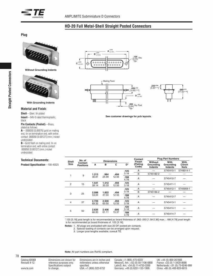
78Catalog 82068 Dimensions are shown for Dimensions are in inches and Canada: +1 (905) 475-6222 UK: +44 (0) 800-267666Revised 4-12 reference purposes only. millimeters unless otherwise Mexico/C. Am.: +52 (0) 55-1106-0800 France: +33 (0) 1-3420-8686
Specifications subject specified. Latin/S. Am.: +54 (0) 11-4733-2200 Netherlands: +31 (0) 73-6246-999www.te.com to change. USA: +1 (800) 522-6752 Germany: +49 (0) 6251-133-1999 China: +86 (0) 400-820-6015
AMPLIMITE Subminiature D Connectors
Note: All part numbers are RoHS compliant.
StraightPo
sted
Connectors
HD-20 Full Metal-Shell Straight Posted Connectors
Plug
Material and Finish:Shell—Steel, tin platedInsert—94V-0 rated thermoplastic,blackPin Contacts (Posted)—Brass,plated as follows:A—.000030 [0.00076] gold on matingend, tin on termination end, with entirecontact .000050 [0.00127] (min.) nickelunderplatedB—Gold flash on mating end, tin ontermination end, with entire contact.000050 [0.00127] (min.) nickelunderplated
Technical Documents:Product Specification—108-40025
Without Grounding Indents
Contact Plug Part NumbersShell No. of Dimensions Finish Without With WithSize Contact
A B C *D* (Plating Grounding Grounding ClinchPositions Code) Indents Indents Nuts
1.213 .984 .494.125 A — 5745410-1 5749014-1
1 9 30.81 24.99 12.553.18 B 5745182-2 — —.188 A — 5745410-7 —4.78
1.541 1.312 .494 .125 A — 5745411-1 —2 15 39.14 33.33 12.55 3.18
2.088 1.852 .494.125 A — 5745412-1 5745959-1
3 25 53.04 47.04 12.553.18 B 5745186-2 — —.188 A — 5745412-7 —4.78
4 37 2.729 2.500 .494 .125 A — 5745413-1 —69.32 63.50 12.55 3.18.125 A — 5745414-1 —
5 50 2.635 2.406 .605 3.1866.93 61.11 15.37 .188
4.78 A — 5745414-7 —
*.125 [3.18] post length is for recommended pc board thickness of .062-.093 [1.58-2.36] max.; .188 [4.78] post lengthis for recommended pc board thickness of .125 [3.18].Notes: 1. All plugs are preloaded with size 20 DF posted pin contacts.
2. Special loading of contacts can be arranged upon request.3. Longer post lengths available, consult TE.
With Grounding Indents.025[0.64] Sq. Post
Typ.
Mating Face
.426±.010[10.82±0.25]
.230±.006[5.84±0.15]
.689±.015[17.50±0.38]
.120[3.05] Dia.
Typ.
±.030D [±0.762]
±.015A [±0.381]
±.010B [±0.254]
±.015C [±0.381]
See customer drawings for pcb layouts.
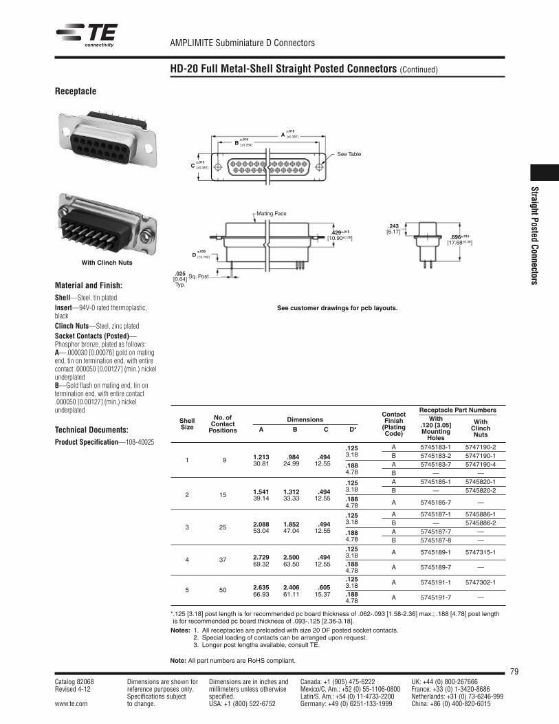
79Catalog 82068 Dimensions are shown for Dimensions are in inches and Canada: +1 (905) 475-6222 UK: +44 (0) 800-267666Revised 4-12 reference purposes only. millimeters unless otherwise Mexico/C. Am.: +52 (0) 55-1106-0800 France: +33 (0) 1-3420-8686
Specifications subject specified. Latin/S. Am.: +54 (0) 11-4733-2200 Netherlands: +31 (0) 73-6246-999www.te.com to change. USA: +1 (800) 522-6752 Germany: +49 (0) 6251-133-1999 China: +86 (0) 400-820-6015
AMPLIMITE Subminiature D Connectors
Note: All part numbers are RoHS compliant.
StraightPostedConnectors
HD-20 Full Metal-Shell Straight Posted Connectors (Continued)
Receptacle
Material and Finish:Shell—Steel, tin platedInsert—94V-0 rated thermoplastic,blackClinch Nuts—Steel, zinc platedSocket Contacts (Posted)—Phosphor bronze, plated as follows:A—.000030 [0.00076] gold on matingend, tin on termination end, with entirecontact .000050 [0.00127] (min.) nickelunderplatedB—Gold flash on mating end, tin ontermination end, with entire contact.000050 [0.00127] (min.) nickelunderplated
Technical Documents:Product Specification—108-40025
.025[0.64] Sq. Post
Typ.
Mating Face
.429±.015[10.90±0.38]
.243[6.17]
.696±.015[17.68±0.38]
See Table
ContactReceptacle Part Numbers
No. of Finish With WithShell ContactDimensions
(Plating .120 [3.05] ClinchSize Positions A B C *D*Code) Mounting NutsHoles
1.213 .984 .494.125 A 5745183-1 5747190-2
1 9 30.81 24.99 12.553.18 B 5745183-2 5747190-1
.188 A 5745183-7 5747190-44.78 B — —
1.541 1.312 .494.125 A 5745185-1 5745820-1
2 15 39.14 33.33 12.553.18 B — 5745820-2.188 A 5745185-7 —4.78
2.088 1.852 .494.125 A 5745187-1 5745886-1
3 25 53.04 47.04 12.553.18 B — 5745886-2
.188 A 5745187-7 —4.78 B 5745187-8 —
2.729 2.500 .494.125 A 5745189-1 5747315-1
4 3769.32 63.50 12.55
3.18.188 A 5745189-7 —4.78
2.635 2.406 .605.125 A 5745191-1 5747302-1
5 5066.93 61.11 15.37
3.18.188 A 5745191-7 —4.78
*.125 [3.18] post length is for recommended pc board thickness of .062-.093 [1.58-2.36] max.; .188 [4.78] post lengthis for recommended pc board thickness of .093-.125 [2.36-3.18].Notes: 1. All receptacles are preloaded with size 20 DF posted socket contacts.
2. Special loading of contacts can be arranged upon request.3. Longer post lengths available, consult TE.
With Clinch Nuts
±.030D [±0.762]
±.015A [±0.381]
±.010B [±0.254]
±.015C [±0.381]
See customer drawings for pcb layouts.
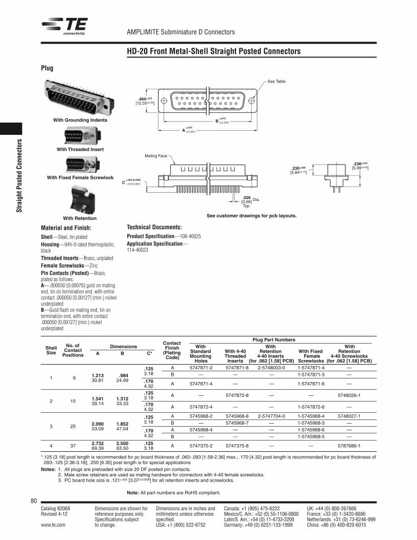
80Catalog 82068 Dimensions are shown for Dimensions are in inches and Canada: +1 (905) 475-6222 UK: +44 (0) 800-267666Revised 4-12 reference purposes only. millimeters unless otherwise Mexico/C. Am.: +52 (0) 55-1106-0800 France: +33 (0) 1-3420-8686
Specifications subject specified. Latin/S. Am.: +54 (0) 11-4733-2200 Netherlands: +31 (0) 73-6246-999www.te.com to change. USA: +1 (800) 522-6752 Germany: +49 (0) 6251-133-1999 China: +86 (0) 400-820-6015
AMPLIMITE Subminiature D Connectors
Note: All part numbers are RoHS compliant.
StraightPo
sted
Connectors
HD-20 Front Metal-Shell Straight Posted Connectors
Plug
Material and Finish:Shell—Steel, tin platedHousing—94V-0 rated thermoplastic,blackThreaded Inserts—Brass, unplatedFemale Screwlocks—ZincPin Contacts (Posted)—Brass,plated as follows:A—.000030 [0.00076] gold on matingend, tin on termination end, with entirecontact .000050 [0.00127] (min.) nickelunderplatedB—Gold flash on mating end, tin ontermination end, with entire contact.000050 [0.00127] (min.) nickelunderplated
With Grounding Indents
With Threaded Insert
With Fixed Female Screwlock
With Retention
Plug Part NumbersNo. of Contact
With With WithContact Finish
Standard With 4-40 Retention With Fixed RetentionShell
Positions
Dimensions(Plating
Mounting Threaded 4-40 Inserts Female 4-40 ScrewlocksSize A B *C*
Code)Holes Inserts (for .062 [1.58] PCB) Screwlocks (for .062 [1.58] PCB)
.125 A 5747871-2 5747871-8 2-5748003-0 1-5747871-4 —
1 9 1.213 .984 3.18 B — — — 1-5747871-3 —30.81 24.99 .170 A 5747871-4 — — 1-5747871-6 —4.32
.125 A — 5747872-8 — — 5748026-12 15 1.541 1.312 3.18
39.14 33.33 .170 A 5747872-4 — — 1-5747872-6 —4.32
.125 A 5745968-2 5745968-8 2-5747704-0 1-5745968-4 5748027-1
3 25 2.090 1.852 3.18 B — 5745968-7 — 1-5745968-3 —53.09 47.04 .170 A 5745968-4 — — 1-5745968-6 —
4.32 B — — — 1-5745968-5 —2.732 2.500 .125 A 5747375-2 5747375-8 — — 5787686-14 37 69.39 63.50 3.18
*.125 [3.18] post length is recommended for pc board thickness of .062-.093 [1.58-2.36] max.; .170 [4.32] post length is recommended for pc board thickness of.093-.125 [2.36-3.18]; .250 [6.35] post length is for special applicationsNotes: 1. All plugs are preloaded with size 20 DF posted pin contacts.
2. Male screw retainers are used as mating hardware for connectors with 4-40 female screwlocks.Notes: 3. PC board hole size is .121±.002 [3.07±0.0508] for all retention inserts and screwlocks.
Mating Face
.230±.006[5.84±0.15]
.236±.010[5.99±0.25]
.494±.015[12.55±0.38]
.026[0.66] Dia.
Typ.
See Table
±.015A [±0.381]
±.010B [±0.254]
+.020 [0.508]C -.015 [0.381]
Technical Documents:Product Specification—108-40025Application Specification—114-40023
See customer drawings for pcb layouts.
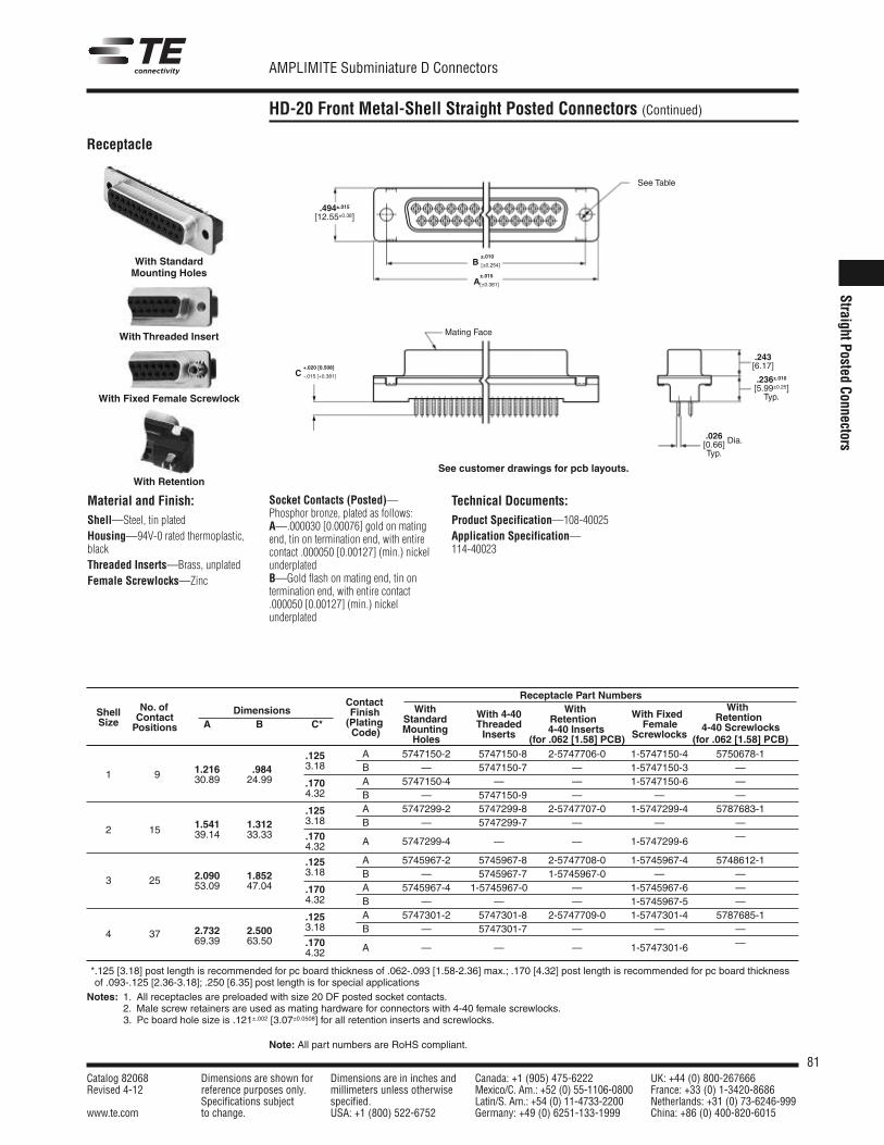
81Catalog 82068 Dimensions are shown for Dimensions are in inches and Canada: +1 (905) 475-6222 UK: +44 (0) 800-267666Revised 4-12 reference purposes only. millimeters unless otherwise Mexico/C. Am.: +52 (0) 55-1106-0800 France: +33 (0) 1-3420-8686
Specifications subject specified. Latin/S. Am.: +54 (0) 11-4733-2200 Netherlands: +31 (0) 73-6246-999www.te.com to change. USA: +1 (800) 522-6752 Germany: +49 (0) 6251-133-1999 China: +86 (0) 400-820-6015
AMPLIMITE Subminiature D Connectors
Note: All part numbers are RoHS compliant.
StraightPostedConnectors
HD-20 Front Metal-Shell Straight Posted Connectors (Continued)
Material and Finish:Shell—Steel, tin platedHousing—94V-0 rated thermoplastic,blackThreaded Inserts—Brass, unplatedFemale Screwlocks—Zinc
With StandardMounting Holes
With Threaded Insert
With Fixed Female Screwlock
With Retention
Mating Face
See Table
.243[6.17]
.236±.010[5.99±0.25]Typ.
.494±.015[12.55±0.38]
.026[0.66] Dia.
Typ.
Receptacle Part NumbersNo. of Contact
With With WithContact Finish
Standard With 4-40 Retention With Fixed RetentionShell
Positions
Dimensions(Plating
Mounting Threaded 4-40 Inserts Female 4-40 ScrewlocksSize A B *C*Code)
Holes Inserts (for .062 [1.58] PCB) Screwlocks (for .062 [1.58] PCB)
1.216 .984.125 A 5747150-2 5747150-8 2-5747706-0 1-5747150-4 5750678-1
1 9 30.89 24.993.18 B — 5747150-7 — 1-5747150-3 —
.170 A 5747150-4 — — 1-5747150-6 —4.32 B — 5747150-9 — — —
.125 A 5747299-2 5747299-8 2-5747707-0 1-5747299-4 5787683-1
2 15 1.541 1.312 3.18 B — 5747299-7 — — —39.14 33.33 .170 A 5747299-4 — — 1-5747299-6 —
4.32
.125 A 5745967-2 5745967-8 2-5747708-0 1-5745967-4 5748612-1
3 25 2.090 1.852 3.18 B — 5745967-7 1-5745967-0 — —53.09 47.04 .170 A 5745967-4 1-5745967-0 — 1-5745967-6 —
4.32 B — — — 1-5745967-5 —
.125 A 5747301-2 5747301-8 2-5747709-0 1-5747301-4 5787685-1
4 37 2.732 2.500 3.18 B — 5747301-7 — — —69.39 63.50 .170 A — — — 1-5747301-6 —
4.32
**.125 [3.18] post length is recommended for pc board thickness of .062-.093 [1.58-2.36] max.; .170 [4.32] post length is recommended for pc board thicknessof .093-.125 [2.36-3.18]; .250 [6.35] post length is for special applications
Notes: 1. All receptacles are preloaded with size 20 DF posted socket contacts.2. Male screw retainers are used as mating hardware for connectors with 4-40 female screwlocks.
Notes: 3. Pc board hole size is .121±.002 [3.07±0.0508] for all retention inserts and screwlocks.
Socket Contacts (Posted)—Phosphor bronze, plated as follows:A—.000030 [0.00076] gold on matingend, tin on termination end, with entirecontact .000050 [0.00127] (min.) nickelunderplatedB—Gold flash on mating end, tin ontermination end, with entire contact.000050 [0.00127] (min.) nickelunderplated
Technical Documents:Product Specification—108-40025Application Specification—114-40023
±.015A[±0.381]
+.020 [0.508]C -.015 [+0.381]
±.010B [±0.254]
Receptacle
See customer drawings for pcb layouts.

82Catalog 82068 Dimensions are shown for Dimensions are in inches and Canada: +1 (905) 475-6222 UK: +44 (0) 800-267666Revised 4-12 reference purposes only. millimeters unless otherwise Mexico/C. Am.: +52 (0) 55-1106-0800 France: +33 (0) 1-3420-8686
Specifications subject specified. Latin/S. Am.: +54 (0) 11-4733-2200 Netherlands: +31 (0) 73-6246-999www.te.com to change. USA: +1 (800) 522-6752 Germany: +49 (0) 6251-133-1999 China: +86 (0) 400-820-6015
AMPLIMITE Subminiature D Connectors
Note: All part numbers are RoHS compliant.
StraightPo
sted
Connectors
HD-20 All-Plastic Straight Posted Connectors
Plug
Material and Finish:Housing—94V-0 rated thermoplastic,blackThreaded Inserts—Brass, unplatedFemale Screwlocks—Brass, nickelplatedPin Contacts (Posted)—Brass,plated as follows:A—.000030 [0.00076] gold on matingend, tin on termination end, with entirecontact .000050 [0.00127] (min.) nickelunderplatedB—Gold flash on mating end, tin ontermination end, with entire contact.000050 [0.00127] (min.) nickelunderplated
Technical Documents:Product Specification—108-40025
Typical Applications
Application of connector with standard mountingholes using Long Female Screwlock Kit No. 207719
Application of connector with 4-40 ThreadedInserts using Short Female Screwlocks includedin Kit No. 207952
Application of connector with 4-40 Fixed FemaleScrewlocks. (See table on next page.)
Note: Hardware parts in illustrations above are not included with the connectors listed in the table on page 83.They are to be supplied by the Customer or, where applicable, purchased separately from TE using the part nos.specified.
Long FemaleScrewlock(1 Kit Req'd.)
Panel(Optional)
Pc Board
WasherHex Nut
WasherScrew
Pc Board
4-40 FixedFemaleScrewlock
Pc Board
4-40ThreadedInsert
Panel
Short FemaleScrewlock(2 Req'd.)
With Standard Mounting Hole
With Threaded Insert
With Fixed Female Screwlock
Mating Face
See Table
.230±.006[5.84±0.15]Typ.
.476±.015[12.09±0.38]
CMax.
AMax.
.026[0.66] Dia.
Typ.
±.010B [±0.254]
+.020
D[-0.508]
+.015[0.381]
See customer drawings for pcb layouts.
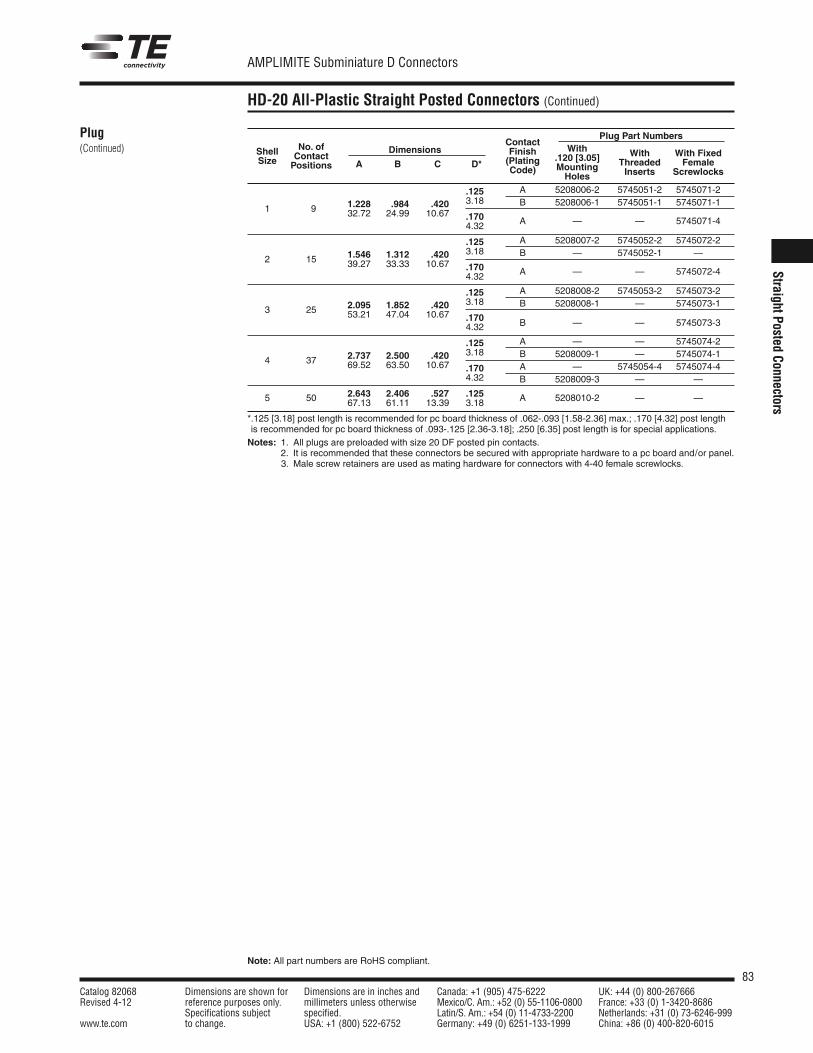
83Catalog 82068 Dimensions are shown for Dimensions are in inches and Canada: +1 (905) 475-6222 UK: +44 (0) 800-267666Revised 4-12 reference purposes only. millimeters unless otherwise Mexico/C. Am.: +52 (0) 55-1106-0800 France: +33 (0) 1-3420-8686
Specifications subject specified. Latin/S. Am.: +54 (0) 11-4733-2200 Netherlands: +31 (0) 73-6246-999www.te.com to change. USA: +1 (800) 522-6752 Germany: +49 (0) 6251-133-1999 China: +86 (0) 400-820-6015
AMPLIMITE Subminiature D Connectors
Note: All part numbers are RoHS compliant.
StraightPostedConnectors
HD-20 All-Plastic Straight Posted Connectors (Continued)
Plug(Continued)
Plug Part NumbersNo. of Contact
WithContact Finish
.120 [3.05] With With FixedShell
Positions
Dimensions(Plating
Mounting Threaded FemaleSize A B C *D*Code)
Holes Inserts Screwlocks
.125 A 5208006-2 5745051-2 5745071-2
1.228 .984 .420 3.18 B 5208006-1 5745051-1 5745071-11 9 32.72 24.99 10.67 .170 A — — 5745071-44.32
.125 A 5208007-2 5745052-2 5745072-2
1.546 1.312 .420 3.18 B — 5745052-1 —2 15 39.27 33.33 10.67 .170 A — — 5745072-44.32
.125 A 5208008-2 5745053-2 5745073-2
2.095 1.852 .420 3.18 B 5208008-1 — 5745073-13 25 53.21 47.04 10.67 .170
4.32 B — — 5745073-3
.125 A — — 5745074-2
2.737 2.500 .420 3.18 B 5208009-1 — 5745074-14 37 69.52 63.50 10.67 .170 A — 5745054-4 5745074-4
4.32 B 5208009-3 — —
5 50 2.643 2.406 .527 .125 A 5208010-2 — —67.13 61.11 13.39 3.18
*.125 [3.18] post length is recommended for pc board thickness of .062-.093 [1.58-2.36] max.; .170 [4.32] post lengthis recommended for pc board thickness of .093-.125 [2.36-3.18]; .250 [6.35] post length is for special applications.Notes: 1. All plugs are preloaded with size 20 DF posted pin contacts.
2. It is recommended that these connectors be secured with appropriate hardware to a pc board and/or panel.Notes: 3. Male screw retainers are used as mating hardware for connectors with 4-40 female screwlocks.
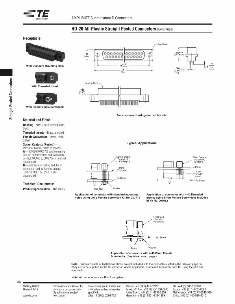
84Catalog 82068 Dimensions are shown for Dimensions are in inches and Canada: +1 (905) 475-6222 UK: +44 (0) 800-267666Revised 4-12 reference purposes only. millimeters unless otherwise Mexico/C. Am.: +52 (0) 55-1106-0800 France: +33 (0) 1-3420-8686
Specifications subject specified. Latin/S. Am.: +54 (0) 11-4733-2200 Netherlands: +31 (0) 73-6246-999www.te.com to change. USA: +1 (800) 522-6752 Germany: +49 (0) 6251-133-1999 China: +86 (0) 400-820-6015
AMPLIMITE Subminiature D Connectors
Note: All part numbers are RoHS compliant.
StraightPo
sted
Connectors
HD-20 All-Plastic Straight Posted Connectors (Continued)
Receptacle
Material and Finish:Housing—94V-0 rated thermoplastic,blackThreaded Inserts—Brass, unplatedFemale Screwlocks—Brass, nickelplatedSocket Contacts (Posted)—Phosphor bronze, plated as follows:A—.000030 [0.00076] gold on matingend, tin on termination end, with entirecontact .000050 [0.00127] (min.) nickelunderplatedB—Gold flash on mating end, tin ontermination end, with entire contact.000050 [0.00127] (min.) nickelunderplated
Technical Documents:Product Specification—108-40025
Typical Applications
Application of connector with 4-40 ThreadedInserts using Short Female Screwlocks includedin Kit No. 207952
Application of connector with 4-40 Fixed FemaleScrewlocks. (See table on next page.)
Note: Hardware parts in illustrations above are not included with the connectors listed in the table on page 85.They are to be supplied by the Customer or, where applicable, purchased separately from TE using the part nos.specified.
Long FemaleScrewlock(1 Kit Req'd.)
Panel(Optional)
Pc Board
WasherHex Nut
WasherScrew
Pc Board
4-40 FixedFemaleScrewlock
Pc Board
4-40ThreadedInsert
Panel
Short FemaleScrewlock(2 Req'd.)
Application of connector with standard mountingholes using Long Female Screwlock Kit No. 207719
With Standard Mounting Hole
With Threaded Insert
With Fixed Female Screwlock
Mating Face
.479±.015[12.17±0.38]
.243[6.17]
.026[0.66] Dia.
Typ.
See Table
CMax.
AMax.
+.020
D[-0.508]
+.015[0.381]
±.010B [±0.25]
See customer drawings for pcb layouts.
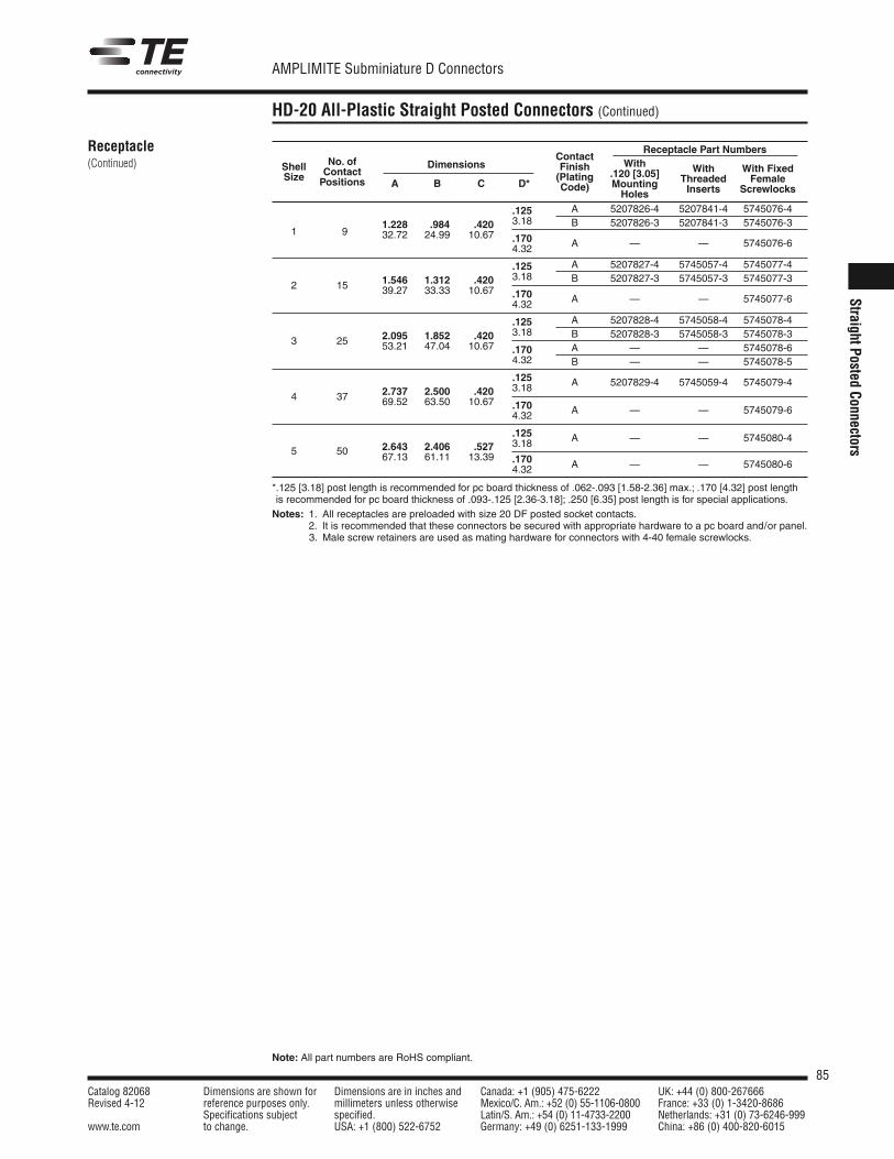
85Catalog 82068 Dimensions are shown for Dimensions are in inches and Canada: +1 (905) 475-6222 UK: +44 (0) 800-267666Revised 4-12 reference purposes only. millimeters unless otherwise Mexico/C. Am.: +52 (0) 55-1106-0800 France: +33 (0) 1-3420-8686
Specifications subject specified. Latin/S. Am.: +54 (0) 11-4733-2200 Netherlands: +31 (0) 73-6246-999www.te.com to change. USA: +1 (800) 522-6752 Germany: +49 (0) 6251-133-1999 China: +86 (0) 400-820-6015
AMPLIMITE Subminiature D Connectors
Note: All part numbers are RoHS compliant.
StraightPostedConnectors
HD-20 All-Plastic Straight Posted Connectors (Continued)
Receptacle(Continued)
Receptacle Part NumbersNo. of Contact
WithContact Finish
.120 [3.05] With With FixedShell
Positions
Dimensions(Plating
Mounting Threaded FemaleSizeA B C *D* Code)
Holes Inserts Screwlocks
.125 A 5207826-4 5207841-4 5745076-4
1.228 .984 .420 3.18 B 5207826-3 5207841-3 5745076-31 9 32.72 24.99 10.67 .170 A — — 5745076-64.32
.125 A 5207827-4 5745057-4 5745077-4
1.546 1.312 .420 3.18 B 5207827-3 5745057-3 5745077-32 15 39.27 33.33 10.67 .170 A — — 5745077-64.32
.125 A 5207828-4 5745058-4 5745078-4
2.095 1.852 .420 3.18 B 5207828-3 5745058-3 5745078-33 25 53.21 47.04 10.67 .170 A — — 5745078-6
4.32 B — — 5745078-5
.125 A 5207829-4 5745059-4 5745079-42.737 2.500 .420 3.18
4 37 69.52 63.50 10.67 .170 A — — 5745079-64.32
.125 A — — 5745080-42.643 2.406 .527 3.18
5 50 67.13 61.11 13.39 .170 A — — 5745080-64.32
*.125 [3.18] post length is recommended for pc board thickness of .062-.093 [1.58-2.36] max.; .170 [4.32] post lengthis recommended for pc board thickness of .093-.125 [2.36-3.18]; .250 [6.35] post length is for special applications.Notes: 1. All receptacles are preloaded with size 20 DF posted socket contacts.
2. It is recommended that these connectors be secured with appropriate hardware to a pc board and/or panel.Notes: 3. Male screw retainers are used as mating hardware for connectors with 4-40 female screwlocks.
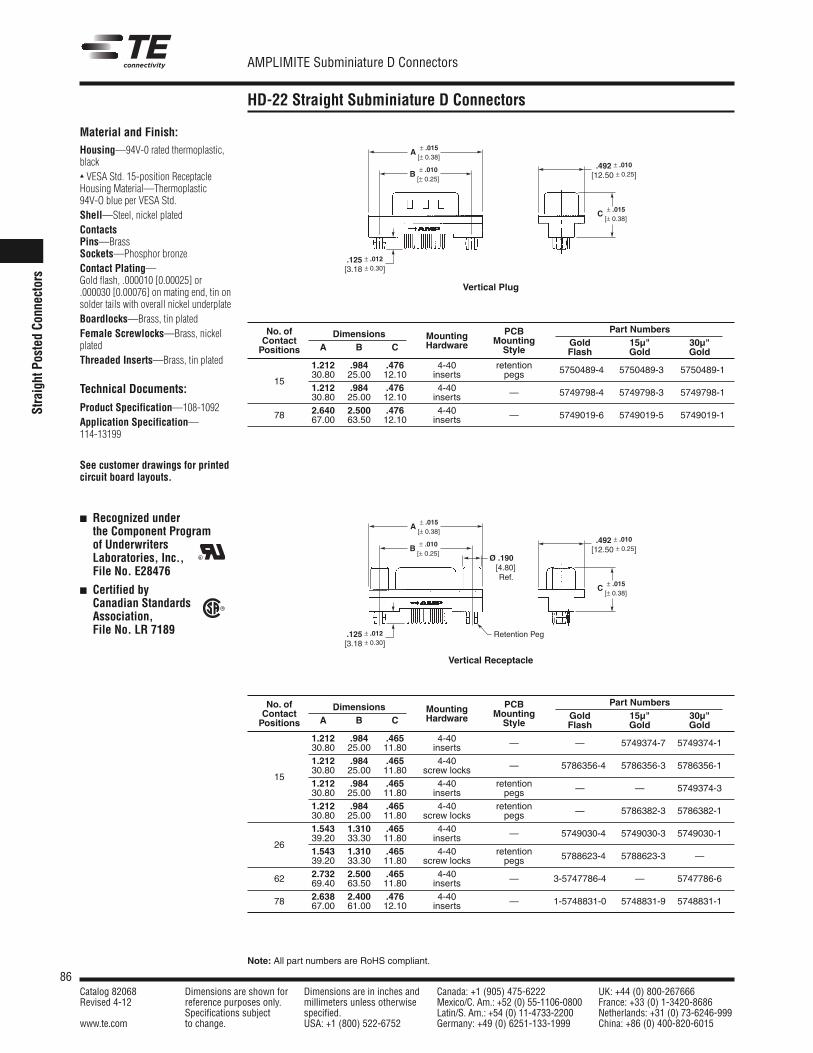
86Catalog 82068 Dimensions are shown for Dimensions are in inches and Canada: +1 (905) 475-6222 UK: +44 (0) 800-267666Revised 4-12 reference purposes only. millimeters unless otherwise Mexico/C. Am.: +52 (0) 55-1106-0800 France: +33 (0) 1-3420-8686
Specifications subject specified. Latin/S. Am.: +54 (0) 11-4733-2200 Netherlands: +31 (0) 73-6246-999www.te.com to change. USA: +1 (800) 522-6752 Germany: +49 (0) 6251-133-1999 China: +86 (0) 400-820-6015
AMPLIMITE Subminiature D Connectors
Note: All part numbers are RoHS compliant.
StraightPo
sted
Connectors
HD-22 Straight Subminiature D Connectors
.125 ± .012
[3.18 ± 0.30]
A ± .015 [± 0.38]
B ± .010 [± 0.25]
C ± .015[± 0.38]
.492 ± .010
[12.50 ± 0.25]
Vertical Plug
.125 ± .012
[3.18 ± 0.30]Retention Peg
A ± .015 [± 0.38]
B ± .010 [± 0.25]
C ± .015[± 0.38]
Ø .190[4.80]Ref.
.492 ± .010
[12.50 ± 0.25]
Vertical Receptacle
Material and Finish:Housing—94V-0 rated thermoplastic,black VESA Std. 15-position ReceptacleHousing Material—Thermoplastic94V-O blue per VESA Std.Shell—Steel, nickel platedContactsPins—BrassSockets—Phosphor bronzeContact Plating—Gold flash, .000010 [0.00025] or.000030 [0.00076] on mating end, tin onsolder tails with overall nickel underplateBoardlocks—Brass, tin platedFemale Screwlocks—Brass, nickelplatedThreaded Inserts—Brass, tin plated
Technical Documents:
Product Specification—108-1092Application Specification—114-13199
See customer drawings for printedcircuit board layouts.
Recognized underthe Component Programof UnderwritersLaboratories, Inc.,File No. E28476
Certified byCanadian StandardsAssociation,File No. LR 7189
R
R
No. of Dimensions PCB Part NumbersContact
A B CMounting Mounting Gold 15µ" 30µ"
Positions Hardware Style Flash Gold Gold1.212 .984 .476 4-40 retention 5750489-4 5750489-3 5750489-1
1530.80 25.00 12.10 inserts pegs1.212 .984 .476 4-40 — 5749798-4 5749798-3 5749798-130.80 25.00 12.10 inserts
78 2.640 2.500 .476 4-40 — 5749019-6 5749019-5 5749019-167.00 63.50 12.10 inserts
No. of Dimensions PCB Part NumbersContact
A B CMounting Mounting Gold 15µ" 30µ"
Positions Hardware Style Flash Gold Gold1.212 .984 .465 4-40 — — 5749374-7 5749374-130.80 25.00 11.80 inserts1.212 .984 .465 4-40 — 5786356-4 5786356-3 5786356-1
1530.80 25.00 11.80 screw locks1.212 .984 .465 4-40 retention — — 5749374-330.80 25.00 11.80 inserts pegs1.212 .984 .465 4-40 retention — 5786382-3 5786382-130.80 25.00 11.80 screw locks pegs1.543 1.310 .465 4-40 — 5749030-4 5749030-3 5749030-1
2639.20 33.30 11.80 inserts1.543 1.310 .465 4-40 retention 5788623-4 5788623-3 —39.20 33.30 11.80 screw locks pegs
62 2.732 2.500 .465 4-40 — 3-5747786-4 — 5747786-669.40 63.50 11.80 inserts
78 2.638 2.400 .476 4-40 — 1-5748831-0 5748831-9 5748831-167.00 61.00 12.10 inserts
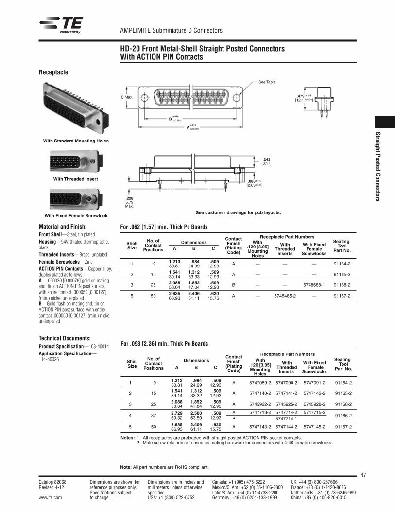
87Catalog 82068 Dimensions are shown for Dimensions are in inches and Canada: +1 (905) 475-6222 UK: +44 (0) 800-267666Revised 4-12 reference purposes only. millimeters unless otherwise Mexico/C. Am.: +52 (0) 55-1106-0800 France: +33 (0) 1-3420-8686
Specifications subject specified. Latin/S. Am.: +54 (0) 11-4733-2200 Netherlands: +31 (0) 73-6246-999www.te.com to change. USA: +1 (800) 522-6752 Germany: +49 (0) 6251-133-1999 China: +86 (0) 400-820-6015
AMPLIMITE Subminiature D Connectors
Note: All part numbers are RoHS compliant.
StraightPostedConnectors
HD-20 Front Metal-Shell Straight Posted ConnectorsWith ACTION PIN Contacts
Receptacle Part NumbersContactWith With
No. of Finish.120 [3.05] With Fixed
SeatingShell ContactDimensions
(PlatingMounting Threaded Female
ToolSize Positions A B CCode)
Holes Inserts ScrewlocksPart No.
1.213 .984 .509 A — — — 91164-21 9 30.81 24.99 12.931.541 1.312 .509 A — — — 91165-22 15 39.14 33.33 12.932.088 1.852 .5093 25 53.04 47.04 12.93 B — — 5748688-1 91168-2
2.635 2.406 .620 A — 5748485-2 — 91167-25 50 66.93 61.11 15.75
Receptacle Part NumbersContact
With WithNo. of Finish
.120 [3.05] With FixedSeatingShell Contact
Dimensions(Plating
Mounting Threaded FemaleToolSize Positions A B C
Code)Holes Inserts Screwlocks
Part No.
1.213 .984 .509 A 5747089-2 5747090-2 5747091-2 91164-21 9 30.81 24.99 12.931.541 1.312 .509 A 5747140-2 5747141-2 5747142-2 91165-22 15 39.14 33.32 12.932.088 1.852 .509 A 5745922-2 5745925-2 5745928-2 91168-23 25 53.04 47.04 12.93
2.729 2.500 .509 A 5747713-2 5747714-2 5747715-291166-24 37 69.32 63.50 12.93 B — 5747714-1 —
2.635 2.406 .620 A 5747143-2 5747144-2 5747145-2 91167-25 50 66.93 61.11 15.75
Notes: 1. All receptacles are preloaded with straight posted ACTION PIN socket contacts.2. Male screw retainers are used as mating hardware for connectors with 4-40 female screwlocks.
Material and Finish:Front Shell—Steel, tin platedHousing—94V-0 rated thermoplastic,blackThreaded Inserts—Brass, unplatedFemale Screwlocks—ZincACTION PIN Contacts—Copper alloy,duplex plated as follows:A—.000030 [0.00076] gold on matingend, tin on ACTION PIN post surface,with entire contact .000050 [0.00127](min.) nickel underplatedB—Gold flash on mating end, tin onACTION PIN post surface, with entirecontact .000050 [0.00127] (min.) nickelunderplated
Technical Documents:Product Specification—108-40014Application Specification—114-40026
For .062 [1.57] min. Thick Pc Boards
For .093 [2.36] min. Thick Pc Boards
With Fixed Female Screwlock
With Threaded Insert
With Standard Mounting Holes
C Max. .479 ±.015
[12.17±0.38]
.243[6.17]
.080±.010[2.03±0.25]
.228[5.79]Max.
ReceptacleSee Table
±.015A [±0.381]
±.010B [±0.254]
See customer drawings for pcb layouts.
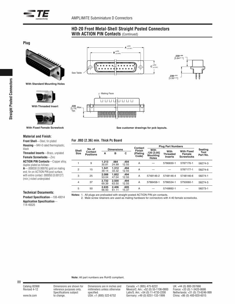
88Catalog 82068 Dimensions are shown for Dimensions are in inches and Canada: +1 (905) 475-6222 UK: +44 (0) 800-267666Revised 4-12 reference purposes only. millimeters unless otherwise Mexico/C. Am.: +52 (0) 55-1106-0800 France: +33 (0) 1-3420-8686
Specifications subject specified. Latin/S. Am.: +54 (0) 11-4733-2200 Netherlands: +31 (0) 73-6246-999www.te.com to change. USA: +1 (800) 522-6752 Germany: +49 (0) 6251-133-1999 China: +86 (0) 400-820-6015
AMPLIMITE Subminiature D Connectors
Note: All part numbers are RoHS compliant.
StraightPo
sted
Connectors
HD-20 Front Metal-Shell Straight Posted ConnectorsWith ACTION PIN Contacts (Continued)
Plug
Material and Finish:Front Shell—Steel, tin platedHousing—94V-0 rated thermoplastic,blackThreaded Inserts—Brass, unplatedFemale Screwlocks—ZincACTION PIN Contacts—Copper alloy,duplex plated as follows:A—.000030 [0.00076] gold on matingend, tin on ACTION PIN post surface,with entire contact .000050 [0.00127](min.) nickel underplated
Technical Documents:Product Specification—108-40014Application Specification—114-40026
.228[5.79]Typ.
Max.
Plug Part NumbersDimensions Contact
With WithNo. of Finish
.120 [3.05] With FixedSeatingShell Contact A B C (Plating
Mounting Threaded FemaleToolSize Positions Code)
Holes Inserts ScrewlocksPart No.
1.213 .984 .494 A — 5786830-1 5787176-1 58274-31 9 30.81 24.99 12.551.541 1.312 .494 A — — 5787177-1 58274-62 15 39.14 33.32 12.552.088 1.852 .494 A 5748146-2 5748146-4 5748146-6 58274-13 25 53.04 47.04 12.552.732 2.500 .494 A 5788458-1 5786534-1 5750060-1 58274-54 37 69.39 63.50 12.552.635 2.406 .605 A — 5749892-1 — 58273-15 50 66.93 61.11 15.37
Notes: 1. All plugs are preloaded with straight posted ACTION PIN pin contacts.2. Male screw retainers are used as mating hardware for connectors with 4-40 female screwlocks.
For .093 [2.36] min. Thick Pc Board
With Threaded Insert
With Standard Mounting Holes
With Fixed Female Screwlock
Mating Face
.230±.006[5.84±0.15]
.236±.010[5.99±0.25]
See Table
±.015A [±0.381]
±.010B [±0.254]
±.015C [±0.381]
See customer drawings for pcb layouts.
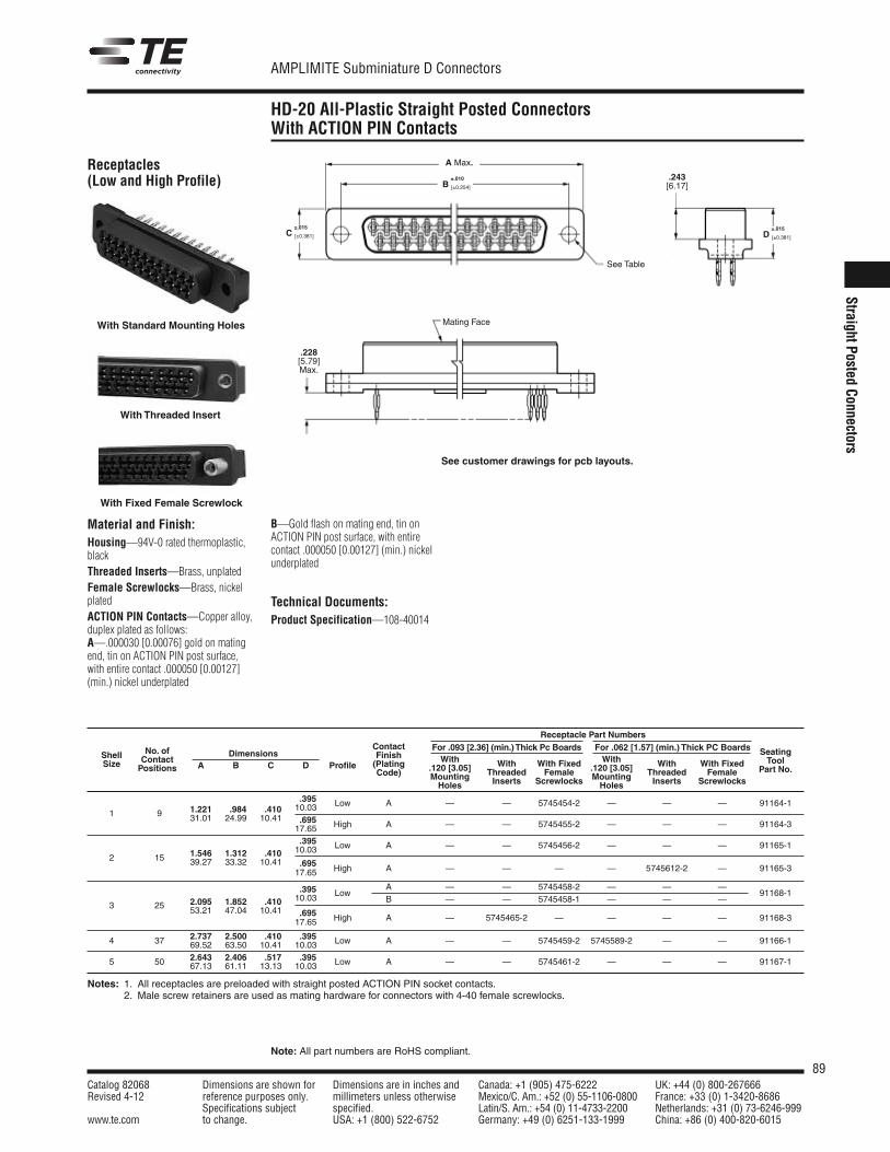
89Catalog 82068 Dimensions are shown for Dimensions are in inches and Canada: +1 (905) 475-6222 UK: +44 (0) 800-267666Revised 4-12 reference purposes only. millimeters unless otherwise Mexico/C. Am.: +52 (0) 55-1106-0800 France: +33 (0) 1-3420-8686
Specifications subject specified. Latin/S. Am.: +54 (0) 11-4733-2200 Netherlands: +31 (0) 73-6246-999www.te.com to change. USA: +1 (800) 522-6752 Germany: +49 (0) 6251-133-1999 China: +86 (0) 400-820-6015
AMPLIMITE Subminiature D Connectors
Note: All part numbers are RoHS compliant.
StraightPostedConnectors
HD-20 All-Plastic Straight Posted ConnectorsWith ACTION PIN Contacts
Receptacles(Low and High Profile)
With Threaded Insert
With Standard Mounting Holes
With Fixed Female Screwlock
A Max.
.228[5.79]Max.
See Table
Mating Face
.243[6.17]
±.015D [±0.381]
±.010B [±0.254]
±.015C [±0.381]
Receptacle Part NumbersFor .093 [2.36] (min.)Thick Pc Boards For .062 [1.57] (min.) Thick PC BoardsContactWith With
No. of Finish.120 [3.05] With With Fixed .120 [3.05] With With Fixed
SeatingShell ContactDimensions
(PlatingMounting Threaded Female Mounting Threaded Female
ToolSize Positions A B C D ProfileCode)
Holes Inserts Screwlocks Holes Inserts ScrewlocksPart No.
.395 Low A — — 5745454-2 — — — 91164-11 9 1.221 .984 .410 10.03
31.01 24.99 10.41 .695 High A — — 5745455-2 — — — 91164-317.65.395 Low A — — 5745456-2 — — — 91165-1
2 15 1.546 1.312 .410 10.0339.27 33.32 10.41 .695 High A — — — — 5745612-2 — 91165-317.65
2.095 1.852 .410.395 Low
A — — 5745458-2 — — —91168-1
3 25 53.21 47.04 10.4110.03 B — — 5745458-1 — — —
.695 High A — 5745465-2 — — — — 91168-317.65
4 37 2.737 2.500 .410 .395 Low A — — 5745459-2 5745589-2 — — 91166-169.52 63.50 10.41 10.03
5 50 2.643 2.406 .517 .395 Low A — — 5745461-2 — — — 91167-167.13 61.11 13.13 10.03
Notes: 1. All receptacles are preloaded with straight posted ACTION PIN socket contacts.2. Male screw retainers are used as mating hardware for connectors with 4-40 female screwlocks.
Material and Finish:Housing—94V-0 rated thermoplastic,blackThreaded Inserts—Brass, unplatedFemale Screwlocks—Brass, nickelplatedACTION PIN Contacts—Copper alloy,duplex plated as follows:A—.000030 [0.00076] gold on matingend, tin on ACTION PIN post surface,with entire contact .000050 [0.00127](min.) nickel underplated
B—Gold flash on mating end, tin onACTION PIN post surface, with entirecontact .000050 [0.00127] (min.) nickelunderplated
Technical Documents:Product Specification—108-40014
See customer drawings for pcb layouts.
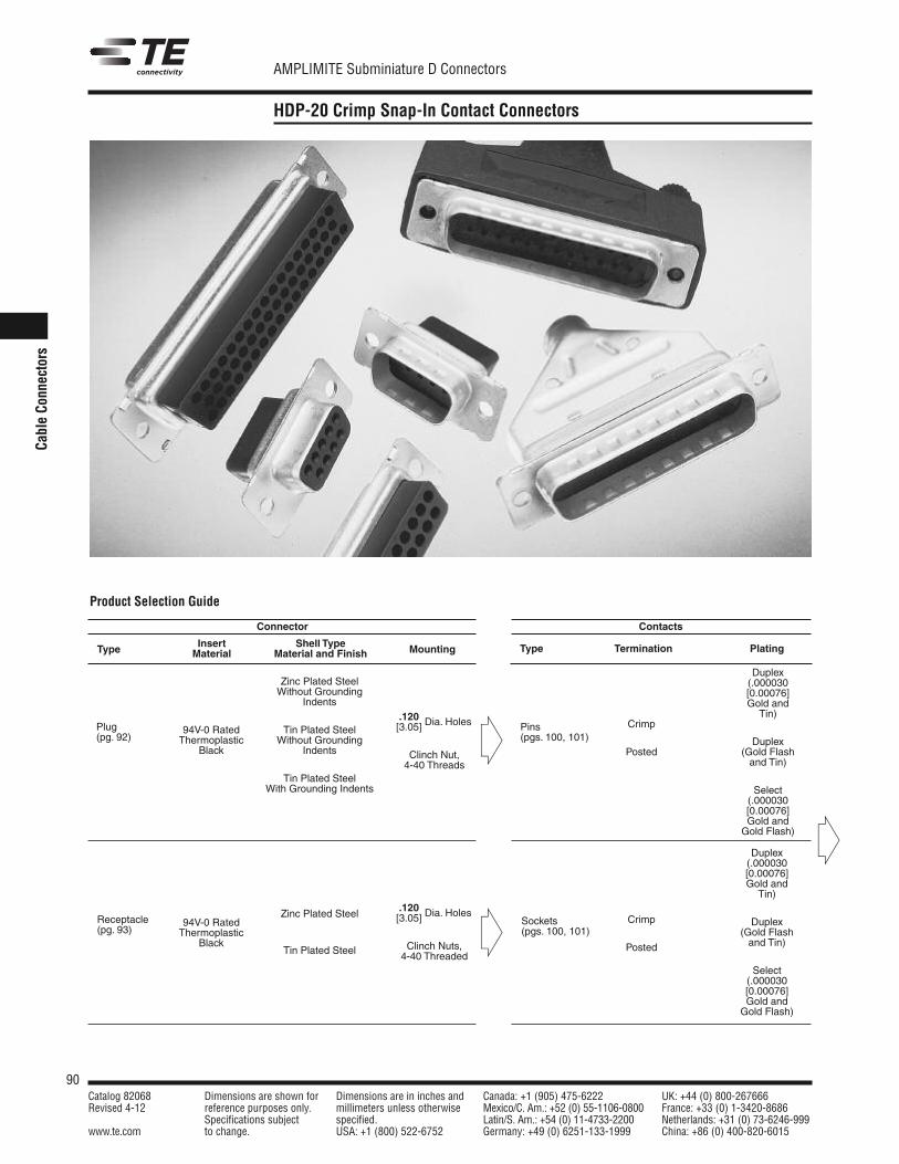
90Catalog 82068 Dimensions are shown for Dimensions are in inches and Canada: +1 (905) 475-6222 UK: +44 (0) 800-267666Revised 4-12 reference purposes only. millimeters unless otherwise Mexico/C. Am.: +52 (0) 55-1106-0800 France: +33 (0) 1-3420-8686
Specifications subject specified. Latin/S. Am.: +54 (0) 11-4733-2200 Netherlands: +31 (0) 73-6246-999www.te.com to change. USA: +1 (800) 522-6752 Germany: +49 (0) 6251-133-1999 China: +86 (0) 400-820-6015
AMPLIMITE Subminiature D Connectors
CableCo
nnectors
HDP-20 Crimp Snap-In Contact Connectors
Connector
Insert Shell TypeType Material Material and Finish Mounting
94V-0 RatedThermoplastic
Black
94V-0 RatedThermoplastic
Black
Plug(pg. 92)
Receptacle(pg. 93)
Zinc Plated SteelWithout Grounding
Indents
Tin Plated SteelWithout Grounding
Indents
Tin Plated SteelWith Grounding Indents
Zinc Plated Steel
Tin Plated Steel
.120[3.05] Dia. Holes
Clinch Nut,4-40 Threads
.120[3.05] Dia. Holes
Clinch Nuts,4-40 Threaded
Contacts
Type Termination Plating
Pins(pgs. 100, 101)
Sockets(pgs. 100, 101)
Crimp
Posted
Crimp
Posted
Duplex(.000030[0.00076]Gold and
Tin)
Duplex(Gold Flashand Tin)
Select(.000030[0.00076]Gold andGold Flash)
Duplex(.000030[0.00076]Gold and
Tin)
Duplex(Gold Flashand Tin)
Select(.000030[0.00076]Gold andGold Flash)
Product Selection Guide
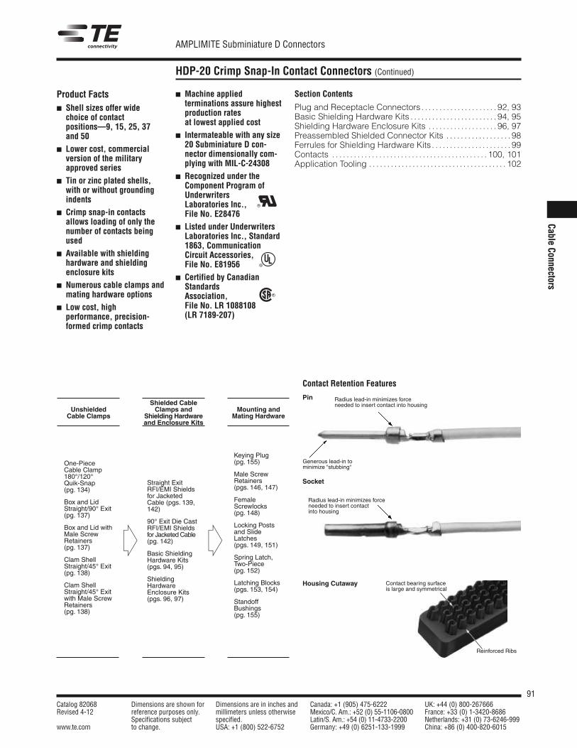
91Catalog 82068 Dimensions are shown for Dimensions are in inches and Canada: +1 (905) 475-6222 UK: +44 (0) 800-267666Revised 4-12 reference purposes only. millimeters unless otherwise Mexico/C. Am.: +52 (0) 55-1106-0800 France: +33 (0) 1-3420-8686
Specifications subject specified. Latin/S. Am.: +54 (0) 11-4733-2200 Netherlands: +31 (0) 73-6246-999www.te.com to change. USA: +1 (800) 522-6752 Germany: +49 (0) 6251-133-1999 China: +86 (0) 400-820-6015
AMPLIMITE Subminiature D Connectors
Cable Connectors
HDP-20 Crimp Snap-In Contact Connectors (Continued)
UnshieldedCable Clamps
One-PieceCable Clamp180°/120°Quik-Snap(pg. 134)
Box and LidStraight/90° Exit(pg. 137)
Box and Lid withMale ScrewRetainers(pg. 137)
Clam ShellStraight/45° Exit(pg. 138)
Clam ShellStraight/45° Exitwith Male ScrewRetainers(pg. 138)
Section Contents
Plug and Receptacle Connectors . . . . . . . . . . . . . . . . . . . . . 92, 93Basic Shielding Hardware Kits . . . . . . . . . . . . . . . . . . . . . . . . 94, 95Shielding Hardware Enclosure Kits . . . . . . . . . . . . . . . . . . . 96, 97Preassembled Shielded Connector Kits . . . . . . . . . . . . . . . . . . 98Ferrules for Shielding Hardware Kits . . . . . . . . . . . . . . . . . . . . . . 99Contacts . . . . . . . . . . . . . . . . . . . . . . . . . . . . . . . . . . . . . . . . . . . 100, 101Application Tooling . . . . . . . . . . . . . . . . . . . . . . . . . . . . . . . . . . . . . . 102
Shielded CableClamps and
Shielding Hardwareand Enclosure Kits
Straight ExitRFI/EMI Shieldsfor JacketedCable (pgs. 139,142)
90° Exit Die CastRFI/EMI Shieldsfor Jacketed Cable(pg. 142)
Basic ShieldingHardware Kits(pgs. 94, 95)
ShieldingHardwareEnclosure Kits(pgs. 96, 97)
Mounting andMating Hardware
Keying Plug(pg. 155)
Male ScrewRetainers(pgs. 146, 147)
FemaleScrewlocks(pg. 148)
Locking Postsand SlideLatches(pgs. 149, 151)
Spring Latch,Two-Piece(pg. 152)
Latching Blocks(pgs. 153, 154)
StandoffBushings(pg. 155)
Product Facts Shell sizes offer wide
choice of contactpositions—9, 15, 25, 37and 50
Lower cost, commercialversion of the militaryapproved series
Tin or zinc plated shells,with or without groundingindents
Crimp snap-in contactsallows loading of only thenumber of contacts beingused
Available with shieldinghardware and shieldingenclosure kits
Numerous cable clamps andmating hardware options
Low cost, high performance, precision-formed crimp contacts
Machine appliedterminations assure highestproduction ratesat lowest applied cost
Intermateable with any size20 Subminiature D con-nector dimensionally com-plying with MIL-C-24308
Recognized under theComponent Program ofUnderwritersLaboratories Inc.,File No. E28476
Listed under UnderwritersLaboratories Inc., Standard1863, Communication Circuit Accessories, File No. E81956
Certified by CanadianStandardsAssociation,File No. LR 1088108(LR 7189-207)
Contact Retention Features
Pin
Socket
Housing Cutaway
Radius lead-in minimizes forceneeded to insert contact into housing
Radius lead-in minimizes forceneeded to insert contact into housing
Generous lead-in tominimize “stubbing“
Contact bearing surfaceis large and symmetrical
Reinforced Ribs
R
R
R
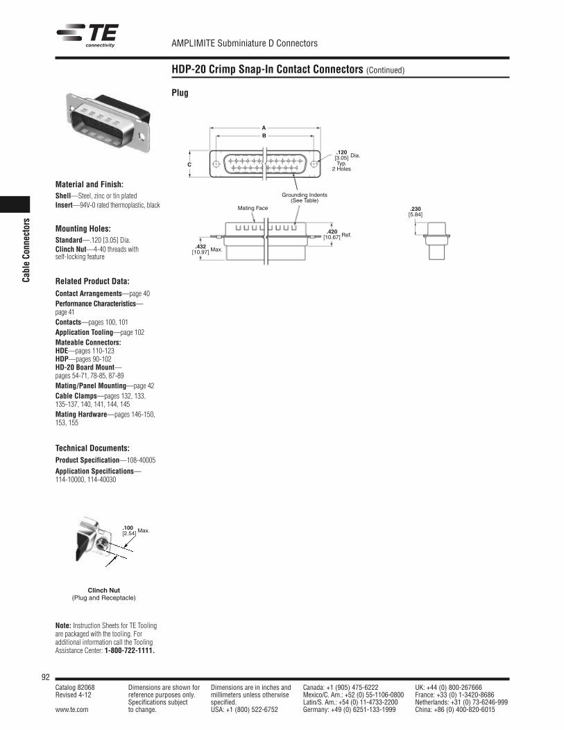
92Catalog 82068 Dimensions are shown for Dimensions are in inches and Canada: +1 (905) 475-6222 UK: +44 (0) 800-267666Revised 4-12 reference purposes only. millimeters unless otherwise Mexico/C. Am.: +52 (0) 55-1106-0800 France: +33 (0) 1-3420-8686
Specifications subject specified. Latin/S. Am.: +54 (0) 11-4733-2200 Netherlands: +31 (0) 73-6246-999www.te.com to change. USA: +1 (800) 522-6752 Germany: +49 (0) 6251-133-1999 China: +86 (0) 400-820-6015
AMPLIMITE Subminiature D Connectors
Cable Co
nnectors
HDP-20 Crimp Snap-In Contact Connectors (Continued)
Material and Finish:Shell—Steel, zinc or tin platedInsert—94V-0 rated thermoplastic, black
Mounting Holes:Standard—.120 [3.05] Dia.Clinch Nut—4-40 threads withself-locking feature
Related Product Data:Contact Arrangements—page 40Performance Characteristics—page 41Contacts—pages 100, 101Application Tooling—page 102Mateable Connectors:HDE—pages 110-123HDP—pages 90-102HD-20 Board Mount—pages 54-71, 78-85, 87-89Mating/Panel Mounting—page 42Cable Clamps—pages 132, 133, 135-137, 140, 141, 144, 145Mating Hardware—pages 146-150,153, 155
Technical Documents:Product Specification—108-40005
Application Specifications—114-10000, 114-40030
Plug
Clinch Nut(Plug and Receptacle)
.100[2.54] Max.
Note: Instruction Sheets for TE Toolingare packaged with the tooling. For additional information call the ToolingAssistance Center: 1-800-722-1111.
.230[5.84]
.420[10.67]
.432[10.97]
.120[3.05]Typ.
2 Holes
AB
C
Dia.
Max.
Ref.
Grounding Indents(See Table)
Mating Face
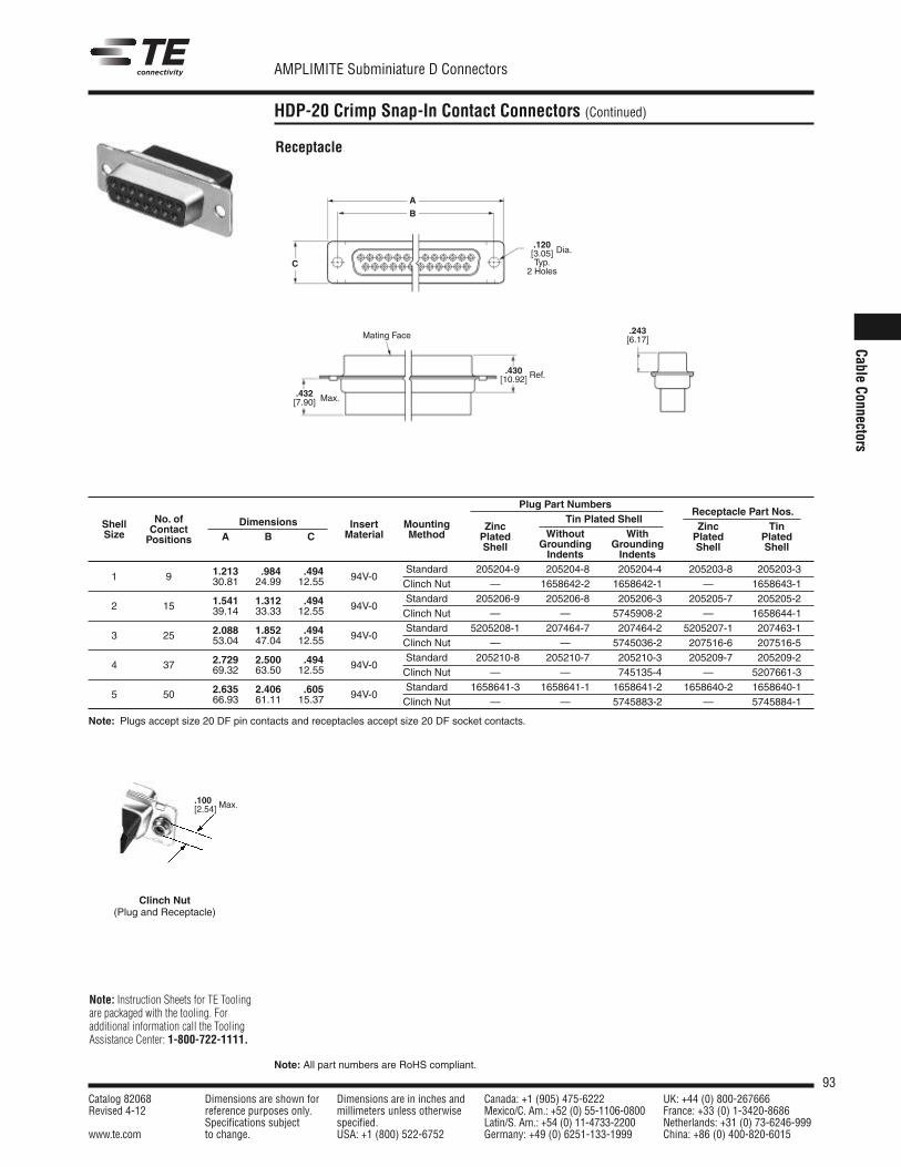
93Catalog 82068 Dimensions are shown for Dimensions are in inches and Canada: +1 (905) 475-6222 UK: +44 (0) 800-267666Revised 4-12 reference purposes only. millimeters unless otherwise Mexico/C. Am.: +52 (0) 55-1106-0800 France: +33 (0) 1-3420-8686
Specifications subject specified. Latin/S. Am.: +54 (0) 11-4733-2200 Netherlands: +31 (0) 73-6246-999www.te.com to change. USA: +1 (800) 522-6752 Germany: +49 (0) 6251-133-1999 China: +86 (0) 400-820-6015
AMPLIMITE Subminiature D Connectors
Note: All part numbers are RoHS compliant.
Cable Connectors
HDP-20 Crimp Snap-In Contact Connectors (Continued)
Receptacle
Plug Part NumbersReceptacle Part Nos.
Shell No. of Dimensions Insert Mounting Tin Plated Shell
Size ContactA B C Material Method
ZincWithout With
Zinc TinPositions Plated
Grounding GroundingPlated Plated
ShellIndents Indents
Shell Shell
1.213 .984 .494 Standard 205204-9 205204-8 205204-4 205203-8 205203-31 9 30.81 24.99 12.55 94V-0
Clinch Nut — 1658642-2 1658642-1 — 1658643-1
2 15 1.541 1.312 .494 94V-0Standard 205206-9 205206-8 205206-3 205205-7 205205-2
39.14 33.33 12.55 * Clinch Nut — — 5745908-2 — 1658644-1
2.088 1.852 .494 Standard 5205208-1 207464-7 207464-2 5205207-1 207463-13 25 53.04 47.04 12.55 94V-0
Clinch Nut — — 5745036-2 207516-6 207516-5
4 37 2.729 2.500 .494 94V-0Standard 205210-8 205210-7 205210-3 205209-7 205209-2
69.32 63.50 12.55 Clinch Nut — — 745135-4 — 5207661-3
5 50 2.635 2.406 .605 94V-0Standard 1658641-3 1658641-1 1658641-2 1658640-2 1658640-1
66.93 61.11 15.37 Clinch Nut — — 5745883-2 — 5745884-1
Note: Plugs accept size 20 DF pin contacts and receptacles accept size 20 DF socket contacts.
Clinch Nut(Plug and Receptacle)
.100[2.54] Max.
Note: Instruction Sheets for TE Toolingare packaged with the tooling. For additional information call the ToolingAssistance Center: 1-800-722-1111.
.243[6.17]
.430[10.92]
.432[7.90]
.120[3.05]Typ.
2 Holes
A
B
C
Dia.
Max.
Ref.
Mating Face
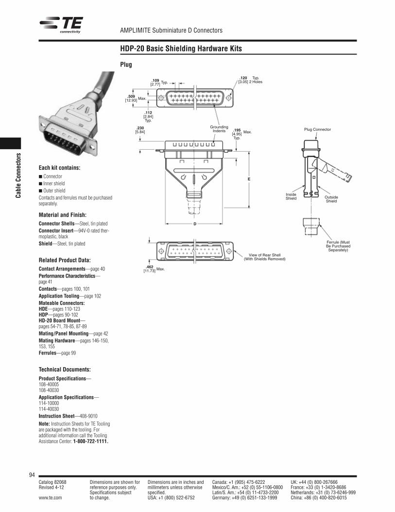
94Catalog 82068 Dimensions are shown for Dimensions are in inches and Canada: +1 (905) 475-6222 UK: +44 (0) 800-267666Revised 4-12 reference purposes only. millimeters unless otherwise Mexico/C. Am.: +52 (0) 55-1106-0800 France: +33 (0) 1-3420-8686
Specifications subject specified. Latin/S. Am.: +54 (0) 11-4733-2200 Netherlands: +31 (0) 73-6246-999www.te.com to change. USA: +1 (800) 522-6752 Germany: +49 (0) 6251-133-1999 China: +86 (0) 400-820-6015
AMPLIMITE Subminiature D Connectors
Cable Co
nnectors
HDP-20 Basic Shielding Hardware Kits
Each kit contains: Connector Inner shield Outer shieldContacts and ferrules must be purchasedseparately.
Material and Finish:Connector Shells—Steel, tin platedConnector Insert—94V-0 rated ther-moplastic, black Shield—Steel, tin plated
Related Product Data:Contact Arrangements—page 40Performance Characteristics—page 41Contacts—pages 100, 101Application Tooling—page 102Mateable Connectors:HDE—pages 110-123HDP—pages 90-102HD-20 Board Mount—pages 54-71, 78-85, 87-89Mating/Panel Mounting—page 42Mating Hardware—pages 146-150,153, 155Ferrules—page 99
Technical Documents:
Product Specifications—108-40005108-40030Application Specifications—114-10000114-40030Instruction Sheet—408-9010
Note: Instruction Sheets for TE Toolingare packaged with the tooling. For additional information call the ToolingAssistance Center: 1-800-722-1111.
Plug
.509[12.93]
.112[2.84]Typ.
.109[2.77] Typ.
Max.
Plug Connector
InsideShield Outside
Shield
.120[3.05]
Typ.2 Holes
D
E
.195[4.95]Typ.
Max.
Ferrule (MustBe PurchasedSeparately)
.462[11.73] Max.
View of Rear Shell(With Shields Removed)
GroundingIndents
.230[5.84]
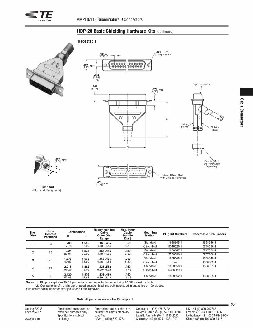
95Catalog 82068 Dimensions are shown for Dimensions are in inches and Canada: +1 (905) 475-6222 UK: +44 (0) 800-267666Revised 4-12 reference purposes only. millimeters unless otherwise Mexico/C. Am.: +52 (0) 55-1106-0800 France: +33 (0) 1-3420-8686
Specifications subject specified. Latin/S. Am.: +54 (0) 11-4733-2200 Netherlands: +31 (0) 73-6246-999www.te.com to change. USA: +1 (800) 522-6752 Germany: +49 (0) 6251-133-1999 China: +86 (0) 400-820-6015
AMPLIMITE Subminiature D Connectors
Note: All part numbers are RoHS compliant.
Cable Connectors
HDP-20 Basic Shielding Hardware Kits (Continued)
Recommended Max. InnerShell No. of Dimensions Cable Cable MountingSize Contact
D E Outer Dia. Bundle Method Plug Kit Numbers Receptacle Kit NumbersPositions Range Dia.†
.700 1.535 .165-.455 .350 Standard 1658645-1 1658646-11 9 17.78 38.99 4.19-11.56 8.89 Clinch Nut 5748526-1 5748536-1
1.024 1.535 .165-.455 .350 Standard 1658647-1 5747539-12 15 26.01 38.99 4.19-11.56 8.89 Clinch Nut 5750636-1 5787908-1
1.576 1.535 .165-.455 .350 Standard 1658648-1 1658649-13 25 40.03 38.99 4.16-11.56 8.89 Clinch Nut — 1658662-1
2.215 1.892 .338-.562 .450 Standard 1658650-1 1658651-14 37 56.26 48.06 8.59-14.28 11.43 Clinch Nut 5786929-1 —
5 50 2.120 1.876 .338-.480 .450 Standard 1658652-1 1658653-153.85 47.65 8.59-12.19 11.43
Notes: 1. Plugs accept size 20 DF pin contacts and receptacles accept size 20 DF socket contacts.2. Components of the kits are shipped unassembled and bulk-packaged in quantities of 100 pieces.
†Maximum cable diameter after jacket and braid removed.
Receptacle
.509[12.93]
.112[2.84]Typ.
.109[2.77] Typ.
Max.
.462[11.73] Max.
Rcpt. Connector
InsideShield Outside
Shield
.120[3.05]
Typ.2 Holes
D
.243[6.17]
E
.195[4.95]Typ.
Max.
Ferrule (MustBe PurchasedSeparately)
View of Rear Shell(With Shields Removed)
Clinch Nut(Plug and Receptacle)
.100[2.54] Max.
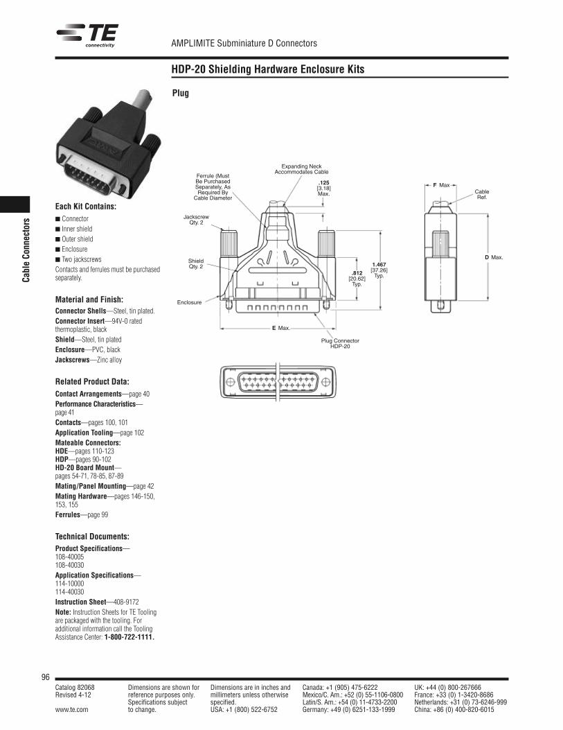
96Catalog 82068 Dimensions are shown for Dimensions are in inches and Canada: +1 (905) 475-6222 UK: +44 (0) 800-267666Revised 4-12 reference purposes only. millimeters unless otherwise Mexico/C. Am.: +52 (0) 55-1106-0800 France: +33 (0) 1-3420-8686
Specifications subject specified. Latin/S. Am.: +54 (0) 11-4733-2200 Netherlands: +31 (0) 73-6246-999www.te.com to change. USA: +1 (800) 522-6752 Germany: +49 (0) 6251-133-1999 China: +86 (0) 400-820-6015
AMPLIMITE Subminiature D Connectors
Cable Co
nnectors
HDP-20 Shielding Hardware Enclosure Kits
.812[20.62]Typ.
.125[3.18]Max.
1.467[37.26]Typ.
Expanding Neck Accommodates Cable
Each Kit Contains: Connector Inner shield Outer shield Enclosure Two jackscrewsContacts and ferrules must be purchasedseparately.
Material and Finish:Connector Shells—Steel, tin plated.Connector Insert—94V-0 ratedthermoplastic, blackShield—Steel, tin platedEnclosure—PVC, blackJackscrews—Zinc alloy
Related Product Data:Contact Arrangements—page 40Performance Characteristics—page 41Contacts—pages 100, 101Application Tooling—page 102Mateable Connectors:HDE—pages 110-123HDP—pages 90-102HD-20 Board Mount—pages 54-71, 78-85, 87-89Mating/Panel Mounting—page 42Mating Hardware—pages 146-150,153, 155Ferrules—page 99
Technical Documents:Product Specifications—108-40005108-40030Application Specifications—114-10000114-40030Instruction Sheet—408-9172Note: Instruction Sheets for TE Toolingare packaged with the tooling. For additional information call the ToolingAssistance Center: 1-800-722-1111.
Plug
F Max
E Max.
Plug ConnectorHDP-20
ShieldQty. 2
JackscrewQty. 2
CableRef.
Ferrule (MustBe PurchasedSeparately, AsRequired By
Cable Diameter
Enclosure
D Max.
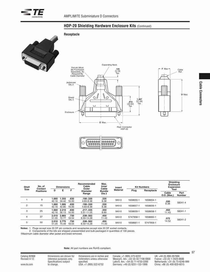
97Catalog 82068 Dimensions are shown for Dimensions are in inches and Canada: +1 (905) 475-6222 UK: +44 (0) 800-267666Revised 4-12 reference purposes only. millimeters unless otherwise Mexico/C. Am.: +52 (0) 55-1106-0800 France: +33 (0) 1-3420-8686
Specifications subject specified. Latin/S. Am.: +54 (0) 11-4733-2200 Netherlands: +31 (0) 73-6246-999www.te.com to change. USA: +1 (800) 522-6752 Germany: +49 (0) 6251-133-1999 China: +86 (0) 400-820-6015
AMPLIMITE Subminiature D Connectors
Note: All part numbers are RoHS compliant.
Cable Connectors
HDP-20 Shielding Hardware Enclosure Kits (Continued)
RecommendedShielding
CableMax. Enclosure
Shell No. of Dimensions Inner Insert Kit Numbers ExpansionSize Contact Outer Cable Material Tool
Positions D E F Diameter Bundle Plug ReceptacleCable PartRange Dia.†
O.D. (Max.) Number1.660 1.355 .630 .190-.330 .330 94V-0 1658655-1 1658654-11 9 42.16 34.42 16.00 4.83-8.38 8.38 .3301.660 1.685 .630 .190-.330 .330 94V-0 1658657-1 1658656-1
8.38 58241-42 15 42.16 42.80 16.00 4.83-8.38 8.38
1.660 2.210 .630 .217-.435 .350 94V-0 1658659-1 1658658-1 .4503 25 42.16 56.13 16.00 5.51-11.05 8.89 11.43 58241-1
2.010 2.865 .730 .338-.562 .450 94V-0 5747958-1 1658660-14 37 51.05 72.77 18.54 8.59-14.28 11.43 .5722.010 2.775 .730 .338-.562 .450 94V-0 1658661-1 5747959-1
14.52 58241-25 50 51.05 70.49 18.54 8.59-14.28 11.43
Notes: 1. Plugs accept size 20 DF pin contacts and receptacles accept size 20 DF socket contacts.2. Components of the kits are shipped unassembled and bulk-packaged in quantities of 100 pieces.
†Maximum cable diameter after jacket and braid removed.
Receptacle
.812[20.62]Typ.
.125[3.18]Typ.
1.467[37.26]Typ.
Expanding Neck
F Max
E Max.
Rcpt. ConnectorHDP-20
ShieldQty. 2
JackscrewQty. 2
CableRef.
Ferrule (MustBe PurchasedSeparately, AsRequired By
Cable Diameter
Enclosure
D Max.
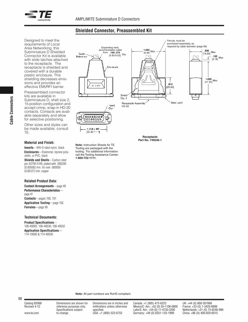
98Catalog 82068 Dimensions are shown for Dimensions are in inches and Canada: +1 (905) 475-6222 UK: +44 (0) 800-267666Revised 4-12 reference purposes only. millimeters unless otherwise Mexico/C. Am.: +52 (0) 55-1106-0800 France: +33 (0) 1-3420-8686
Specifications subject specified. Latin/S. Am.: +54 (0) 11-4733-2200 Netherlands: +31 (0) 73-6246-999www.te.com to change. USA: +1 (800) 522-6752 Germany: +49 (0) 6251-133-1999 China: +86 (0) 400-820-6015
AMPLIMITE Subminiature D Connectors
Note: All part numbers are RoHS compliant.
Cable Co
nnectors
Shielded Connector, Preassembled Kit
Designed to meet therequirements of Local Area Networking, thisSubminiature D ShieldedConnector Kit is availablewith slide latches attachedto the receptacle. Thereceptacle is shielded andcovered with a durableplastic enclosure. Thisshielding decreases emis-sions and provides aneffective EMI/RFI barrier.
Preassembled connectorkits are available inSubminiature D, shell size 2,15-position configuration andaccept crimp, snap-in HD-20contacts. Contacts are avail-able separately and allowfor selective positioning.
Other sizes and styles can be made available, consultTE.
Material and Finish:Inserts—94V-0 rated nylon, blackEnclosures—Elastomer, styrene poly-olefin, or PVC, blackShields and Shells—Carbon steelper ASTM A109, plated with .000200[0.00508] min. tin over .000050[0.00127] min. copper
Related Product Data:Contact Arrangements—page 40Performance Characteristics—page 41Contacts—pages 100, 101Application Tooling—page 102Ferrules—page 99
Technical Documents:Product Specifications—108-40005, 108-40030, 108-40032Application Specifications—114-10000 & 114-40030
ReceptaclePart No. 749246-1
Note: Instruction Sheets for TETooling are packaged with the tooling. For additional informationcall the Tooling Assistance Center:1-800-722-1111.
Expanding neck,accommodates cable
from .190-.375[4.83-9.53] Dia.
1.685 Max.42.80
Max.
Ferrule, must bepurchased separately, asrequired by cable diameter (page 99)
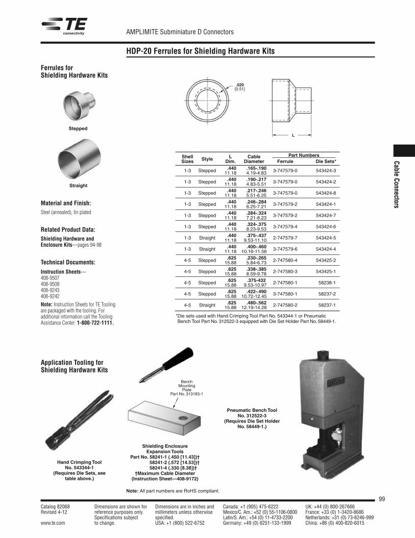
99Catalog 82068 Dimensions are shown for Dimensions are in inches and Canada: +1 (905) 475-6222 UK: +44 (0) 800-267666Revised 4-12 reference purposes only. millimeters unless otherwise Mexico/C. Am.: +52 (0) 55-1106-0800 France: +33 (0) 1-3420-8686
Specifications subject specified. Latin/S. Am.: +54 (0) 11-4733-2200 Netherlands: +31 (0) 73-6246-999www.te.com to change. USA: +1 (800) 522-6752 Germany: +49 (0) 6251-133-1999 China: +86 (0) 400-820-6015
AMPLIMITE Subminiature D Connectors
Note: All part numbers are RoHS compliant.
Cable Connectors
HDP-20 Ferrules for Shielding Hardware Kits
Shell L Cable Part NumbersSizes Style Dim. Diameter Ferrule Die Sets*
.440 .165-.1901-3 Stepped 11.18 4.19-4.83 3-747579-0 543424-3
.440 .190-.2171-3 Stepped 11.18 4.83-5.51 3-747579-0 543424-2
.440 .217-.2461-3 Stepped 11.18 5.51-6.25 3-747579-0 543424-8
.440 .246-.2841-3 Stepped 11.18 6.25-7.21 3-747579-2 543424-1
.440 .284-.3241-3 Stepped 11.18 7.21-8.23 3-747579-2 543424-7
.440 .324-.3751-3 Stepped 11.18 8.23-9.53 3-747579-4 543424-6
.440 .375-.4371-3 Straight 11.18 9.53-11.10 2-747579-7 543424-5
.440 .400-.4601-3 Straight 11.18 10.16-11.56 3-747579-6 543424-4
.625 .230-.2654-5 Stepped 15.88 5.84-6.73 2-747580-4 543425-2
.625 .338-.3854-5 Stepped 15.88 8.59-9.78 2-747580-3 543425-1
.625 .375-4324-5 Stepped 15.88 9.53-10.97 2-747580-1 58238-1
.625 .422-.4904-5 Stepped 15.88 10.72-12.45 3-747580-1 58237-2
.625 .480-.5624-5 Straight 15.88 12.19-14.28 2-747580-2 58237-1
Ferrules forShielding Hardware Kits
Application Tooling forShielding Hardware Kits
Hand Crimping ToolNo. 543344-1
(Requires Die Sets, seetable above.)
Pneumatic Bench ToolNo. 312522-3
(Requires Die Set HolderNo. 58449-1.)
*Die sets used with Hand Crimping Tool Part No. 543344-1 or PneumaticBench Tool Part No. 312522-3 equipped with Die Set Holder Part No. 58449-1.
L
.020[0.51]
Material and Finish:Steel (annealed), tin plated
Related Product Data:Shielding Hardware andEnclosure Kits—pages 94-98
Technical Documents:
Instruction Sheets—408-9507408-9508408-9243408-9242
Note: Instruction Sheets for TE Toolingare packaged with the tooling. For additional information call the ToolingAssistance Center: 1-800-722-1111.
Shielding EnclosureExpansion Tools
Part No. 58241-1 (.450 [11.43])†Part No. 58241-2 (.572 [14.53])†Part No. 58241-4 (.330 [8.38])†0†Maximum Cable Diameter(Instruction Sheet—408-9172)
BenchMountingPlate
Part No. 313183-1
Stepped
Straight
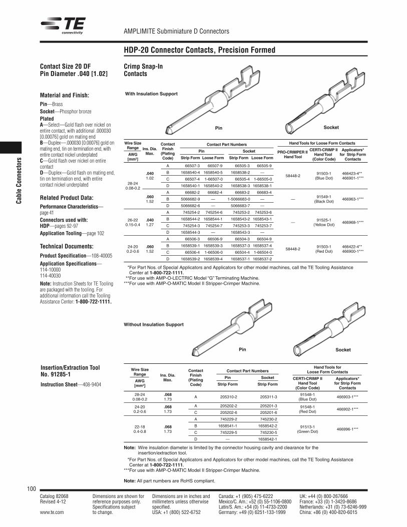
100Catalog 82068 Dimensions are shown for Dimensions are in inches and Canada: +1 (905) 475-6222 UK: +44 (0) 800-267666Revised 4-12 reference purposes only. millimeters unless otherwise Mexico/C. Am.: +52 (0) 55-1106-0800 France: +33 (0) 1-3420-8686
Specifications subject specified. Latin/S. Am.: +54 (0) 11-4733-2200 Netherlands: +31 (0) 73-6246-999www.te.com to change. USA: +1 (800) 522-6752 Germany: +49 (0) 6251-133-1999 China: +86 (0) 400-820-6015
AMPLIMITE Subminiature D Connectors
Note: All part numbers are RoHS compliant.
Cable Co
nnectors
HDP-20 Connector Contacts, Precision Formed
Contact Size 20 DFPin Diameter .040 [1.02]
Material and Finish:Pin—BrassSocket—Phosphor bronzePlatedA—Select—Gold flash over nickel onentire contact, with additional .000030[0.00076] gold on mating endB—Duplex—.000030 [0.00076] gold onmating end, tin on termination end, withentire contact nickel underplatedC—Gold flash over nickel on entire contactD—Duplex—Gold flash on mating end,tin on termination end, with entire contact nickel underplated
Related Product Data:Performance Characteristics—page 41Connectors used with:HDP—pages 92-97Application Tooling—page 102
Technical Documents:
Product Specification—108-40005
Application Specifications—114-10000114-40030
Note: Instruction Sheets for TE Toolingare packaged with the tooling. For additional information call the ToolingAssistance Center: 1-800-722-1111.
Insertion/Extraction ToolNo. 91285-1
Instruction Sheet—408-9404
Without Insulation Support
Pin Socket
Pin Socket
Wire Size Contact Hand Tools for Loose Form ContactsRange Finish
Contact Part NumbersCERTI-CRIMP II Applicators*
AWGIns. Dia.
(Plating Pin Socket PRO-CRIMPER II Hand Tool for Strip Form[mm2]
Max.Code) Strip Form Loose Form Strip Form Loose Form Hand Tool (Color Code) Contacts
A 66507-3 66507-9 66505-3 66505-9
.040 B 1658540-4 1658540-5 1658538-2 — 91503-1 466423-4***1.02 C 66507-4 1-66507-0 66505-4 1-66505-0
58448-2(Blue Dot) 466901-1***
28-24D 1658540-1 1658540-2 1658538-3 1658538-1
0.08-0.2
.060A 66682-2 66682-4 66683-2 66683-4
1.52B 5066682-9 — 1-5066683-0 — —
91549-1466963-1***
D 5066682-6 — 5066683-7 —(Black Dot)
A 745254-2 745254-6 745253-2 745253-6
26-22 .040 B 1658544-2 1658544-1 1658543-2 1658543-1 91525-10.15-0.4 1.27 C 745254-3 745254-7 745253-3 745253-7
—(Yellow Dot)
466968-1***
D 1658544-3 — 1658543-3 —
A 66506-3 66506-9 66504-3 66504-9
24-20 .060 B 1658539-1 1658539-3 1658537-3 1658537-4 91503-1 466422-4***0.2-0.6 1.52 C 66506-4 1-66506-0 66504-4 1-66504-0
58448-2(Red Dot) 466900-1***
D 1658539-2 1658539-4 1658537-1 1658537-2
***For Part Nos. of Special Applicators and Applicators for other model machines, call the TE Tooling AssistanceCenter at 1-800-722-1111.
***For use with AMP-O-LECTRIC Model “G” Terminating Machine.***For use with AMP-O-MATIC Model II Stripper-Crimper Machine.
Hand Tools forWire Size Contact Contact Part Numbers Loose Form ContactsRange Ins. Dia. Finish Pin Socket CERTI-CRIMP II Applicators*AWG Max. (PlatingStrip Form Strip Form Hand Tool for Strip Form[mm2] Code)
(Color Code) Contacts
28-24 .068A 205310-2 205311-3
91548-1466903-1***
0.08-0.2 1.73 (Blue Dot)
24-20 .068 A 205202-2 205201-3 91548-10.2-0.6 1.73 C 205202-6 205201-6 (Red Dot)
466902-1***
A 745229-2 745230-2
22-18 .068 B 1658541-1 1658542-2 91513-10.4-0.8 1.73 C 745229-5 745230-5 (Green Dot)
466996-1***
D — 1658542-1
Note: Wire insulation diameter is limited by the connector housing cavity and clearance for theinsertion/extraction tool.
***For Part Nos. of Special Applicators and Applicators for other model machines, call the TE Tooling AssistanceCenter at 1-800-722-1111.
***For use with AMP-O-MATIC Model II Stripper-Crimper Machine.
With Insulation Support
Crimp Snap-InContacts
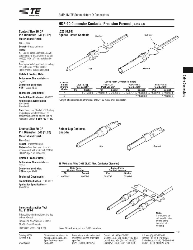
101Catalog 82068 Dimensions are shown for Dimensions are in inches and Canada: +1 (905) 475-6222 UK: +44 (0) 800-267666Revised 4-12 reference purposes only. millimeters unless otherwise Mexico/C. Am.: +52 (0) 55-1106-0800 France: +33 (0) 1-3420-8686
Specifications subject specified. Latin/S. Am.: +54 (0) 11-4733-2200 Netherlands: +31 (0) 73-6246-999www.te.com to change. USA: +1 (800) 522-6752 Germany: +49 (0) 6251-133-1999 China: +86 (0) 400-820-6015
AMPLIMITE Subminiature D Connectors
Note: All part numbers are RoHS compliant.
Cable Connectors
HDP-20 Connector Contacts, Precision Formed (Continued)
Contact Size 20 DFPin Diameter .040 [1.02]Material and Finish:Pin—BrassSocket—Phosphor bronzePlated:A—Duplex plated .000030 [0.00076]gold on mating end, with entire contact.000050 [0.00127] min. nickel under-platedB—Duplex plated gold flash on matingend, with entire contact .000050[0.00127] min. nickel underplated
Related Product Data:Performance Characteristics—page 41Connectors used with:HDP—pages 92, 93
Technical Documents:
Product Specification—108-40005Application Specifications—114-10000114-40030
Note: Instruction Sheets for TE Toolingare packaged with the tooling. For additional information call the ToolingAssistance Center: 1-800-722-1111.
.025 [0.64] Square Posted Contacts
Contact Loose Form Contact NumbersFinish .125 [3.18] .188 [4.78] .427 [10.85] .651 [16.54](Plating Post Length* Post Length* Post Length* Post Length*Code) Pin Socket Pin Socket Pin Socket Pin SocketA — 5-745288-5 5-745287-4 7-745288-0 4-745287-7 5-745288-8 5-745287-0 6-745288-1B — — — — — 7-745288-2 — 7-745288-2
*Length of post extending from rear of HDP-20 metal-shell connector.
SocketPin
Stabilizer Stabilizer
Insertion/Extraction Tool No. 91285-1This tool includes interchangeable tipsto Insert/Extract: Size 22, 28-22 AWG [0.08-0.4 mm2]Size 20, Posted Contacts(Instruction Sheet—408-9404)
Contact Size 20 DFPin Diameter .040 [1.02]Material and Finish:Pin—BrassSocket—Phosphor bronzePlated—Gold flash over nickel onentire contact, with additional .000030[0.00076] gold on mating end
Related Product Data:Performance Characteristics—page 41Connectors used with:HDP—pages 92-97
Technical Documents:
Product Specification—108-40005Application Specification—114-40030
SocketPin
Strip Form Loose FormContact Number Contact Number
Pin Socket Pin Socket66570-2 66569-2 66570-3 66569-3
18 AWG Max. Wire (.046 [1.17] Max. Conductor Diameter)
Note:Contacts to besoldered to wirebefore beinginserted intohousing
Solder Cup Contacts,Snap-In
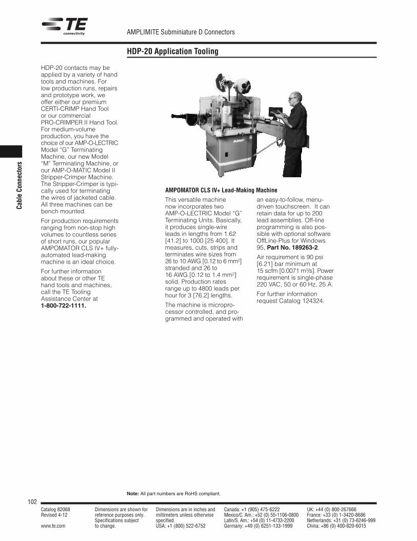
102Catalog 82068 Dimensions are shown for Dimensions are in inches and Canada: +1 (905) 475-6222 UK: +44 (0) 800-267666Revised 4-12 reference purposes only. millimeters unless otherwise Mexico/C. Am.: +52 (0) 55-1106-0800 France: +33 (0) 1-3420-8686
Specifications subject specified. Latin/S. Am.: +54 (0) 11-4733-2200 Netherlands: +31 (0) 73-6246-999www.te.com to change. USA: +1 (800) 522-6752 Germany: +49 (0) 6251-133-1999 China: +86 (0) 400-820-6015
AMPLIMITE Subminiature D Connectors
Note: All part numbers are RoHS compliant.
Cable Co
nnectors
HDP-20 Application Tooling
HDP-20 contacts may beapplied by a variety of handtools and machines. Forlow production runs, repairsand prototype work, weoffer either our premiumCERTI-CRIMP Hand Toolor our commercialPRO-CRIMPER II Hand Tool.For medium-volume production, you have thechoice of our AMP-O-LECTRICModel “G” TerminatingMachine, our new Model“M” Terminating Machine, orour AMP-O-MATIC Model IIStripper-Crimper Machine.The Stripper-Crimper is typi-cally used for terminatingthe wires of jacketed cable.All three machines can bebench mounted.
For production requirementsranging from non-stop highvolumes to countless seriesof short runs, our popularAMPOMATOR CLS IV+ fully-automated lead-makingmachine is an ideal choice.
For further information about these or other TEhand tools and machines,call the TE ToolingAssistance Center at 1-800-722-1111.
This versatile machine now incorporates two AMP-O-LECTRIC Model “G”Terminating Units. Basically,it produces single-wireleads in lengths from 1.62[41.2] to 1000 [25 400]. Itmeasures, cuts, strips andterminates wire sizes from26 to 10 AWG [0.12 to 6 mm2]stranded and 26 to 16 AWG [0.12 to 1.4 mm2]solid. Production ratesrange up to 4800 leads perhour for 3 [76.2] lengths.
The machine is micropro-cessor controlled, and pro -grammed and operated with
an easy-to-follow, menu-driven touchscreen. It canretain data for up to 200lead assemblies. Off-lineprogramming is also pos-sible with optional softwareOffLine-Plus for Windows95, Part No. 189263-2.
Air requirement is 90 psi [6.21] bar minimum at 15 scfm [0.0071 m3/s]. Powerrequirement is single-phase220 VAC, 50 or 60 Hz, 25 A.
For further informationrequest Catalog 124324.
AMPOMATOR CLS IV+ Lead-Making Machine
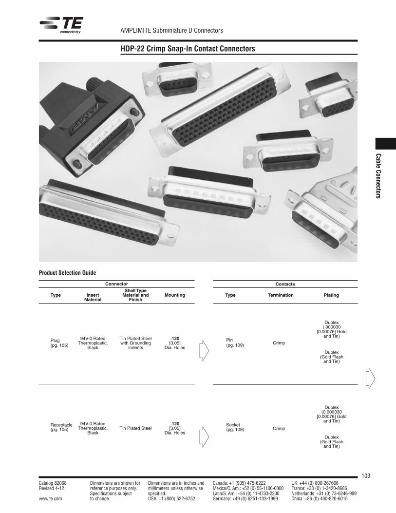
103Catalog 82068 Dimensions are shown for Dimensions are in inches and Canada: +1 (905) 475-6222 UK: +44 (0) 800-267666Revised 4-12 reference purposes only. millimeters unless otherwise Mexico/C. Am.: +52 (0) 55-1106-0800 France: +33 (0) 1-3420-8686
Specifications subject specified. Latin/S. Am.: +54 (0) 11-4733-2200 Netherlands: +31 (0) 73-6246-999www.te.com to change. USA: +1 (800) 522-6752 Germany: +49 (0) 6251-133-1999 China: +86 (0) 400-820-6015
AMPLIMITE Subminiature D Connectors
Cable Connectors
HDP-22 Crimp Snap-In Contact Connectors
Contacts
Type Termination Plating
Duplex(.000030
[0.00076] Goldand Tin)
Duplex(Gold Flashand Tin)
Duplex(0.000030
[0.00076] Goldand Tin)
Duplex(Gold Flashand Tin)
Crimp
Crimp
Pin(pg. 109)
Socket(pg. 109)
ConnectorShell Type
Insert Material andTypeMaterial Finish
Mounting
94V-0 Rated Tin Plated Steel .120Plug Thermoplastic, with Grounding [3.05](pg. 105) Black Indents Dia. Holes
94V-0 Rated .120ReceptacleThermoplastic, Tin Plated Steel [3.05](pg. 105)
Black Dia. Holes
Product Selection Guide
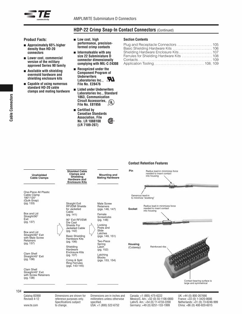
104Catalog 82068 Dimensions are shown for Dimensions are in inches and Canada: +1 (905) 475-6222 UK: +44 (0) 800-267666Revised 4-12 reference purposes only. millimeters unless otherwise Mexico/C. Am.: +52 (0) 55-1106-0800 France: +33 (0) 1-3420-8686
Specifications subject specified. Latin/S. Am.: +54 (0) 11-4733-2200 Netherlands: +31 (0) 73-6246-999www.te.com to change. USA: +1 (800) 522-6752 Germany: +49 (0) 6251-133-1999 China: +86 (0) 400-820-6015
AMPLIMITE Subminiature D Connectors
Cable Co
nnectors
HDP-22 Crimp Snap-In Contact Connectors (Continued)
Shielded CableClamps andShielding
Hardware andEnclosure Kits
One-Piece All PlasticCable Clamp180°/120°(Quik-Snap)(pg. 133)
Box and LidStraight/90°Exit(pg. 137)
Box and LidStraight/90° Exitwith Male ScrewRetainers(pg. 137)
Clam ShellStraight/45° Exit(pg. 138)
Clam ShellStraight/45° Exitwith Screw Retainers(pg. 138)
Product Facts: Approximately 65% higher
density than HD-20connectors
Lower cost, commercialversion of the militaryapproved Series 90 family
Available with shieldingovermold hardware andshielding enclosure kits
Capable of using numerousstandard HD-20 cableclamps and mating hardware
Low cost, highperformance, precision-formed crimp contacts
Intermateable with any size 22 Subminiature Dconnector dimensionallycomplying with MIL-C-24308
Recognized under theComponent Program ofUnderwritersLaboratories Inc.,File No. E28476
Listed under UnderwritersLaboratories Inc., Standard1863, CommunicationCircuit Accessories, File No. E81956
Certified byCanadian StandardsAssociation, FileNo. LR 1088108(LR 7189-207)
Section ContentsPlug and Receptacle Connectors . . . . . . . . . . . . . . . . . . . . . . . 105Basic Shielding Hardware Kits . . . . . . . . . . . . . . . . . . . . . . . . . . 106Shielding Hardware Enclosure Kits . . . . . . . . . . . . . . . . . . . . . . 107Ferrules for Shielding Hardware Kits . . . . . . . . . . . . . . . . . . . . 108Contacts. . . . . . . . . . . . . . . . . . . . . . . . . . . . . . . . . . . . . . . . . . . . . . . . . 109Application Tooling . . . . . . . . . . . . . . . . . . . . . . . . . . . . . . . . . 108, 109
Straight ExitRFI/EMI Shieldsfor JacketedCable(pg. 141)
90° Exit RFI/EMIDie CastShields ForJacketed Cable(pg. 142)
Basic ShieldingHardware Kits(pg. 106)
ShieldingHardwareEnclosure Kits(pg. 107)
Crimp & Split Ring Ferrules (pgs. 143-145)
Male ScrewRetainers(pgs. 146, 147)
FemaleScrewlocks(pg. 148)
LockingPosts andSlideLatches(pgs. 149, 151)
Two-PieceSpringLatch(pg. 152)
LatchingBlocks(pgs. 153, 154)
UnshieldedCable Clamps
Mounting andMating Hardware
Contact Retention Features
Pin
Socket
Housing(Cutaway)
Contact bearing surface islarge and symmetrical
R
R
Generous lead-in to minimize “stubbing”
Radius lead-in minimizes forceneeded to insert contactinto housing
Reinforced ribs
R
Radius lead-in minimizes forceneeded to insert contactinto housing
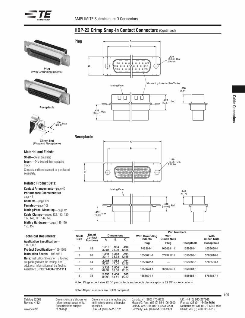
105Catalog 82068 Dimensions are shown for Dimensions are in inches and Canada: +1 (905) 475-6222 UK: +44 (0) 800-267666Revised 4-12 reference purposes only. millimeters unless otherwise Mexico/C. Am.: +52 (0) 55-1106-0800 France: +33 (0) 1-3420-8686
Specifications subject specified. Latin/S. Am.: +54 (0) 11-4733-2200 Netherlands: +31 (0) 73-6246-999www.te.com to change. USA: +1 (800) 522-6752 Germany: +49 (0) 6251-133-1999 China: +86 (0) 400-820-6015
AMPLIMITE Subminiature D Connectors
Note: All part numbers are RoHS compliant.
Cable Connectors
HDP-22 Crimp Snap-In Contact Connectors (Continued)
Receptacle
Material and Finish:Shell—Steel, tin platedInsert—94V-0 rated thermoplastic,blackContacts and ferrules must be purchasedseparately.
Related Product Data:Contact Arrangements—page 40Performance Characteristics—page 41Contacts—page 109Ferrules—page 108Mating/Panel Mounting—page 42Cable Clamps—pages 132, 133, 135-137, 140, 141, 144, 145Mating Hardware—pages 146-150,153, 155
Technical Documents:Application Specification—114-10001Product Specification—108-1268Instruction Sheets—408-9381Note: Instruction Sheets for TE Toolingare packaged with the tooling. For additional information call the ToolingAssistance Center: 1-800-722-1111.
Plug
Clinch Nut(Plug and Receptacle)
.100 [2.54] Max.
Part NumbersShell No. of Dimensions With Grounding With WithSize Contact
A B C Indents Clinch Nuts Clinch NutsPositionsPlug Plug Receptacle Receptacle
1.213 .984 .4941 15 30.81 24.99 12.55 748364-1 1658691-1 1658681-1 1658690-1
1.541 1.312 .4942 26 39.14 33.33 12.55 1658671-1 5749717-1 1658682-1 5788816-1
2.088 1.852 .4943 44 53.84 47.04 12.55 1658672-1 — 1658683-1 5786583-1
2.729 2.500 .4944 62 69.32 63.50 12.55 1658673-1 6658293-1 1658684-1 —
2.635 2.406 .6055 78 66.93 61.11 15.37 1658674-1 — 1658685-1 5788817-1
Note: Plugs accept size 22 DF pin contacts and receptacles accept size 22 DF socket contacts.
A
B
C
A
B
C
.420[10.67]
.230[5.84]
.243[6.17]
.120[3.05]2 Holes
.432[10.97]
Dia.
.120[3.05]2 Holes
Dia.
Max.
Ref.
Ref.
.432[10.97] Max
Grounding Indents (See Table)Mating Face
.430[10.92]
Mating Face
Plug(With Grounding Indents)
Receptacle
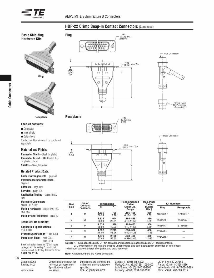
106Catalog 82068 Dimensions are shown for Dimensions are in inches and Canada: +1 (905) 475-6222 UK: +44 (0) 800-267666Revised 4-12 reference purposes only. millimeters unless otherwise Mexico/C. Am.: +52 (0) 55-1106-0800 France: +33 (0) 1-3420-8686
Specifications subject specified. Latin/S. Am.: +54 (0) 11-4733-2200 Netherlands: +31 (0) 73-6246-999www.te.com to change. USA: +1 (800) 522-6752 Germany: +49 (0) 6251-133-1999 China: +86 (0) 400-820-6015
AMPLIMITE Subminiature D Connectors
Note: All part numbers are RoHS compliant.
Cable Co
nnectors
HDP-22 Crimp Snap-In Contact Connectors (Continued)
Basic ShieldingHardware Kits
Each kit contains: Connector Inner shield Outer shieldContacts and ferrules must be purchasedseparately.
Material and Finish:Connector Shell—Steel, tin platedConnector Insert—94V-0 rated ther-moplastic, blackShields—Steel, tin plated
Related Product Data:Contact Arrangements—page 40Performance Characteristics—page 41Contacts—page 109Ferrules—page 108Application Tooling—pages 108 &109Mateable Connectors—pages 105 & 107Mating Hardware—pages 146-150,153, 155Mating/Panel Mounting—page 42
Technical Documents:
Application Specifications—114-10001Product Specification—108-1268Instruction Sheet—408-9381,
408-9010Note: Instruction Sheets for TE Tooling arepackaged with the tooling. For additional information call the Tooling Assistance Center:1-800-722-1111.
Plug
Receptacle
Notes: 1. Plugs accept size 22 DF pin contacts and receptacles accept size 22 DF socket contacts.2. Components of the kits are shipped unassembled and bulk-packaged in quantities of 100 pieces.
†Maximum cable diameter after jacket and braid removed.
.120[3.05]2 Holes
D
.230[5.84]Typ.
C
Dia.
.120[3.05]2 Plc.
Dia.
.195[4.95] Max. Typ.
Rcpt. Connector
Plug Connector
Ferrule (MustBe PurchasedSeparately)
Receptacle
Plug
.243[6.17]
.195[4.95] Max. Typ.
D
C
Recommended Max. InnerShell No. of Dimensions Cable Cable Kit NumbersSize Contact
C D Outer Dia. BundlePositions Range Dia.†Plug Receptacle
1.535 .700 .165-.455 .3501 15 38.99 17.78 4.19-11.56 8.89 1658675-1 5748634-1
1.535 1.024 .165-.455 .3502 26 38.99 26.01 4.19-11.56 8.89 1658676-1 1658687-1
1.535 1.576 .165-.455 .3503 44 38.99 40.03 4.19-11.56 8.89 1658677-1 5748636-1
1.892 2.215 .338-.562 .4504 62 48.06 56.26 8.59-14.28 11.43 5748471-1 —
1.876 2.120 .338-.490 .4505 78 47.65 53.85 8.59-12.45 11.43 5748472-1 —
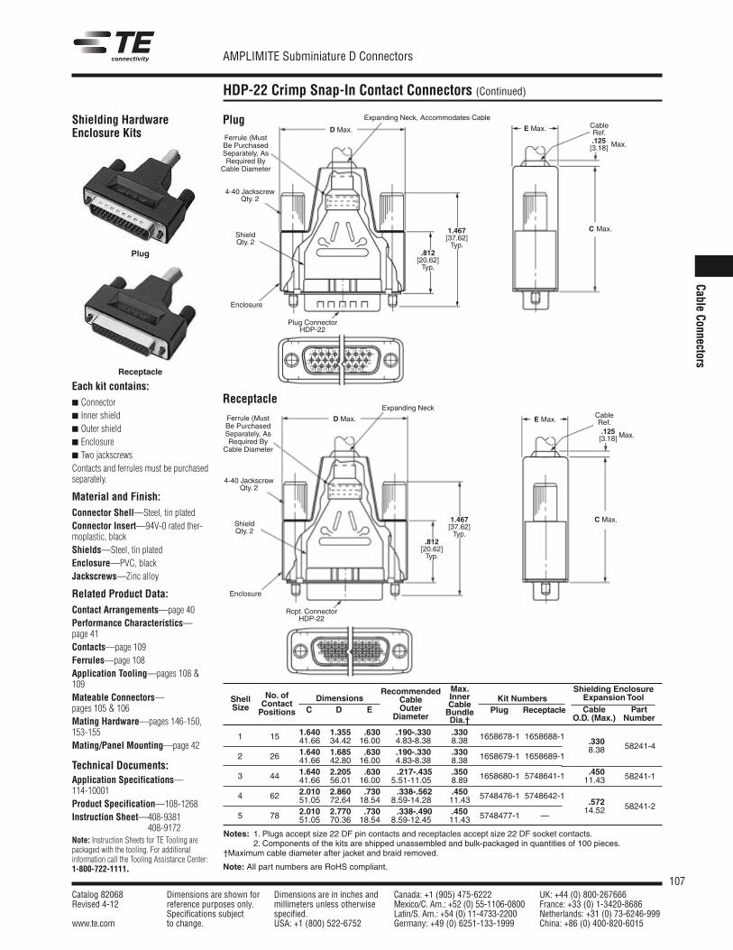
107Catalog 82068 Dimensions are shown for Dimensions are in inches and Canada: +1 (905) 475-6222 UK: +44 (0) 800-267666Revised 4-12 reference purposes only. millimeters unless otherwise Mexico/C. Am.: +52 (0) 55-1106-0800 France: +33 (0) 1-3420-8686
Specifications subject specified. Latin/S. Am.: +54 (0) 11-4733-2200 Netherlands: +31 (0) 73-6246-999www.te.com to change. USA: +1 (800) 522-6752 Germany: +49 (0) 6251-133-1999 China: +86 (0) 400-820-6015
AMPLIMITE Subminiature D Connectors
Note: All part numbers are RoHS compliant.
Cable Connectors
HDP-22 Crimp Snap-In Contact Connectors (Continued)
1658688-1
1658689-1
5748641-1
5748642-1
—
1658678-1
1658679-1
1658680-1
5748476-1
5748477-1
.190-.3304.83-8.38.190-.3304.83-8.38.217-.435
5.51-11.05.338-.562
8.59-14.28.338-.490
8.59-12.45
.63016.00.63016.00.63016.00.73018.54.73018.54
1.35534.421.68542.802.20556.012.86072.642.77070.36
1.64041.661.64041.661.64041.662.01051.052.01051.05
15
26
44
62
78
1
2
3
4
5
58241-4
58241-2
58241-1
.3308.38
.57214.52
.45011.43
Notes: 1. Plugs accept size 22 DF pin contacts and receptacles accept size 22 DF socket contacts.2. Components of the kits are shipped unassembled and bulk-packaged in quantities of 100 pieces.
†Maximum cable diameter after jacket and braid removed.
ShellSize
No. ofContactPositions
RecommendedCableOuter
Diameter
DimensionsC D E
Shielding EnclosureExpansion ToolCable Part
O.D. (Max.) Number
Kit NumbersPlug Receptacle
Each kit contains: Connector Inner shield Outer shield Enclosure Two jackscrewsContacts and ferrules must be purchasedseparately.
Material and Finish:Connector Shell—Steel, tin platedConnector Insert—94V-0 rated ther-moplastic, blackShields—Steel, tin platedEnclosure—PVC, blackJackscrews—Zinc alloy
Related Product Data:Contact Arrangements—page 40Performance Characteristics—page 41Contacts—page 109Ferrules—page 108Application Tooling—pages 108 &109Mateable Connectors—pages 105 & 106Mating Hardware—pages 146-150,153-155Mating/Panel Mounting—page 42
Technical Documents:Application Specifications—114-10001Product Specification—108-1268Instruction Sheet—408-9381
408-9172Note: Instruction Sheets for TE Tooling arepackaged with the tooling. For additional information call the Tooling Assistance Center:1-800-722-1111.
Shielding HardwareEnclosure Kits
Plug
Receptacle
.812[20.62]Typ.
1.467[37.62]Typ.
.125[3.18] Max.
.125[3.18] Max.
C Max.
Plug ConnectorHDP-22
ShieldQty. 2
CableRef.
CableRef.
4-40 JackscrewQty. 2
Ferrule (MustBe PurchasedSeparately, AsRequired By
Cable Diameter
Ferrule (MustBe PurchasedSeparately, AsRequired By
Cable Diameter
Expanding Neck, Accommodates Cable
Expanding Neck
Enclosure
.812[20.62]Typ.
1.467[37.62]Typ.
Rcpt. ConnectorHDP-22
ShieldQty. 2
4-40 JackscrewQty. 2
Enclosure
Receptacle
Plug
Max. InnerCableBundleDia.†.3308.38.3308.38.3508.89.45011.43.45011.43
D Max. E Max.
D Max. E Max.
C Max.
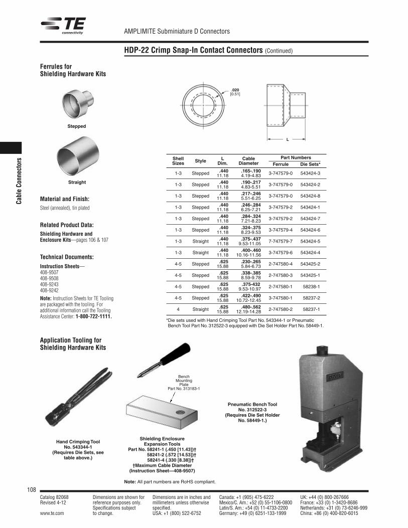
108Catalog 82068 Dimensions are shown for Dimensions are in inches and Canada: +1 (905) 475-6222 UK: +44 (0) 800-267666Revised 4-12 reference purposes only. millimeters unless otherwise Mexico/C. Am.: +52 (0) 55-1106-0800 France: +33 (0) 1-3420-8686
Specifications subject specified. Latin/S. Am.: +54 (0) 11-4733-2200 Netherlands: +31 (0) 73-6246-999www.te.com to change. USA: +1 (800) 522-6752 Germany: +49 (0) 6251-133-1999 China: +86 (0) 400-820-6015
AMPLIMITE Subminiature D Connectors
Note: All part numbers are RoHS compliant.
Cable Co
nnectors
HDP-22 Crimp Snap-In Contact Connectors (Continued)
Material and Finish:Steel (annealed), tin plated
Related Product Data:Shielding Hardware andEnclosure Kits—pages 106 & 107
Technical Documents:
Instruction Sheets—408-9507408-9508408-9243408-9242
Note: Instruction Sheets for TE Toolingare packaged with the tooling. For additional information call the ToolingAssistance Center: 1-800-722-1111.
Ferrules forShielding Hardware Kits
Stepped
Straight
Application Tooling forShielding Hardware Kits
Hand Crimping ToolNo. 543344-1
(Requires Die Sets, seetable above.)
Pneumatic Bench ToolNo. 312522-3
(Requires Die Set HolderNo. 58449-1.)
L
.020[0.51]
Shielding EnclosureExpansion Tools
Part No. 58241-1 (.450 [11.43])†Part No. 58241-2 (.572 [14.53])†
58241-4 (.330 [8.38])††Maximum Cable Diameter(Instruction Sheet—408-9507)
BenchMountingPlate
Part No. 313183-1
Shell L Cable Part NumbersSizes Style Dim. Diameter Ferrule Die Sets*
.440 .165-.1901-3 Stepped 11.18 4.19-4.83 3-747579-0 543424-3
.440 .190-.2171-3 Stepped 11.18 4.83-5.51 3-747579-0 543424-2
.440 .217-.2461-3 Stepped 11.18 5.51-6.25 3-747579-0 543424-8
.440 .246-.2841-3 Stepped 11.18 6.25-7.21 3-747579-2 543424-1
.440 .284-.3241-3 Stepped 11.18 7.21-8.23 3-747579-2 543424-7
.440 .324-.3751-3 Stepped 11.18 8.23-9.53 3-747579-4 543424-6
.440 .375-.4371-3 Straight 11.18 9.53-11.05 7-747579-7 543424-5
.440 .400-.4601-3 Straight 11.18 10.16-11.56 3-747579-6 543424-4
.625 .230-.2654-5 Stepped 15.88 5.84-6.73 2-747580-4 543425-2
.625 .338-.3854-5 Stepped 15.88 8.59-9.78 2-747580-3 543425-1
.625 .375-4324-5 Stepped 15.88 9.53-10.97 2-747580-1 58238-1
.625 .422-.4904-5 Stepped 15.88 10.72-12.45 3-747580-1 58237-2
.625 .480-.5624 Straight 15.88 12.19-14.28 2-747580-2 58237-1
*Die sets used with Hand Crimping Tool Part No. 543344-1 or PneumaticBench Tool Part No. 312522-3 equipped with Die Set Holder Part No. 58449-1.
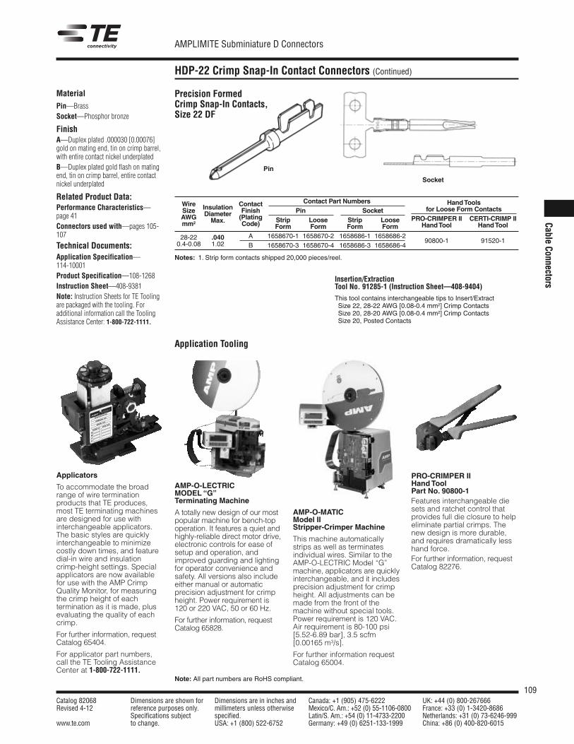
109Catalog 82068 Dimensions are shown for Dimensions are in inches and Canada: +1 (905) 475-6222 UK: +44 (0) 800-267666Revised 4-12 reference purposes only. millimeters unless otherwise Mexico/C. Am.: +52 (0) 55-1106-0800 France: +33 (0) 1-3420-8686
Specifications subject specified. Latin/S. Am.: +54 (0) 11-4733-2200 Netherlands: +31 (0) 73-6246-999www.te.com to change. USA: +1 (800) 522-6752 Germany: +49 (0) 6251-133-1999 China: +86 (0) 400-820-6015
AMPLIMITE Subminiature D Connectors
Note: All part numbers are RoHS compliant.
Cable Connectors
HDP-22 Crimp Snap-In Contact Connectors (Continued)
Application Tooling
MaterialPin—BrassSocket—Phosphor bronze
FinishA—Duplex plated .000030 [0.00076]gold on mating end, tin on crimp barrel,with entire contact nickel underplatedB—Duplex plated gold flash on matingend, tin on crimp barrel, entire contactnickel underplated
Related Product Data:Performance Characteristics—page 41Connectors used with—pages 105-107
Technical Documents:Application Specification—114-10001Product Specification—108-1268Instruction Sheet—408-9381Note: Instruction Sheets for TE Toolingare packaged with the tooling. For additional information call the ToolingAssistance Center: 1-800-722-1111.
Precision FormedCrimp Snap-In Contacts,Size 22 DF
Pin
Socket
Insertion/ExtractionTool No. 91285-1 (Instruction Sheet—408-9404)
This tool contains interchangeable tips to Insert/ExtractSize 22, 28-22 AWG [0.08-0.4 mm2] Crimp ContactsSize 20, 28-20 AWG [0.08-0.4 mm2] Crimp ContactsSize 20, Posted Contacts
AMP-O-LECTRICMODEL “G”Terminating Machine
A totally new design of our mostpopular machine for bench-topoperation. It features a quiet andhighly-reliable direct motor drive,electronic controls for ease ofsetup and operation, andimproved guarding and lightingfor operator convenience andsafety. All versions also includeeither manual or automaticprecision adjustment for crimpheight. Power requirement is120 or 220 VAC, 50 or 60 Hz.
For further information, requestCatalog 65828.
AMP-O-MATICModel IIStripper-Crimper Machine
This machine automaticallystrips as well as terminatesindividual wires. Similar to theAMP-O-LECTRIC Model “G”machine, applicators are quicklyinterchangeable, and it includesprecision adjust ment for crimpheight. All adjustments can bemade from the front of themachine without special tools.Power requirement is 120 VAC.Air requirement is 80-100 psi [5.52-6.89 bar], 3.5 scfm[0.00165 m3/s].
For further information requestCatalog 65004.
Applicators
To accommodate the broadrange of wire termination products that TE pro duces,most TE terminating machinesare designed for use with interchangeable applicators.The basic styles are quicklyinterchangeable to minimizecostly down times, and featuredial-in wire and insulationcrimp-height settings. Specialappli cators are now availablefor use with the AMP CrimpQuality Monitor, for measuringthe crimp height of each termina tion as it is made, plusevalu ating the quality of eachcrimp.
For further information, requestCatalog 65404.
For applicator part numbers,call the TE Tooling AssistanceCenter at 1-800-722-1111.
PRO-CRIMPER IIHand ToolPart No. 90800-1Features interchangeable diesets and ratchet control thatprovides full die closure to helpeliminate partial crimps. Thenew design is more durable,and requires dramatically lesshand force.For further information, requestCatalog 82276.
Wire Contact Contact Part Numbers Hand ToolsSize Insulation Finish Pin Socket for Loose Form ContactsAWG Diameter (Plating Strip Loose Strip Loose PRO-CRIMPER II CERTI-CRIMP IImm2 Max. Code) Form Form Form Form Hand Tool Hand Tool
28-22 .040 A 1658670-1 1658670-2 1658686-1 1658686-20.4-0.08 1.02 B 1658670-3 1658670-4 1658686-3 1658686-4
90800-1 91520-1
Notes: 1. Strip form contacts shipped 20,000 pieces/reel.
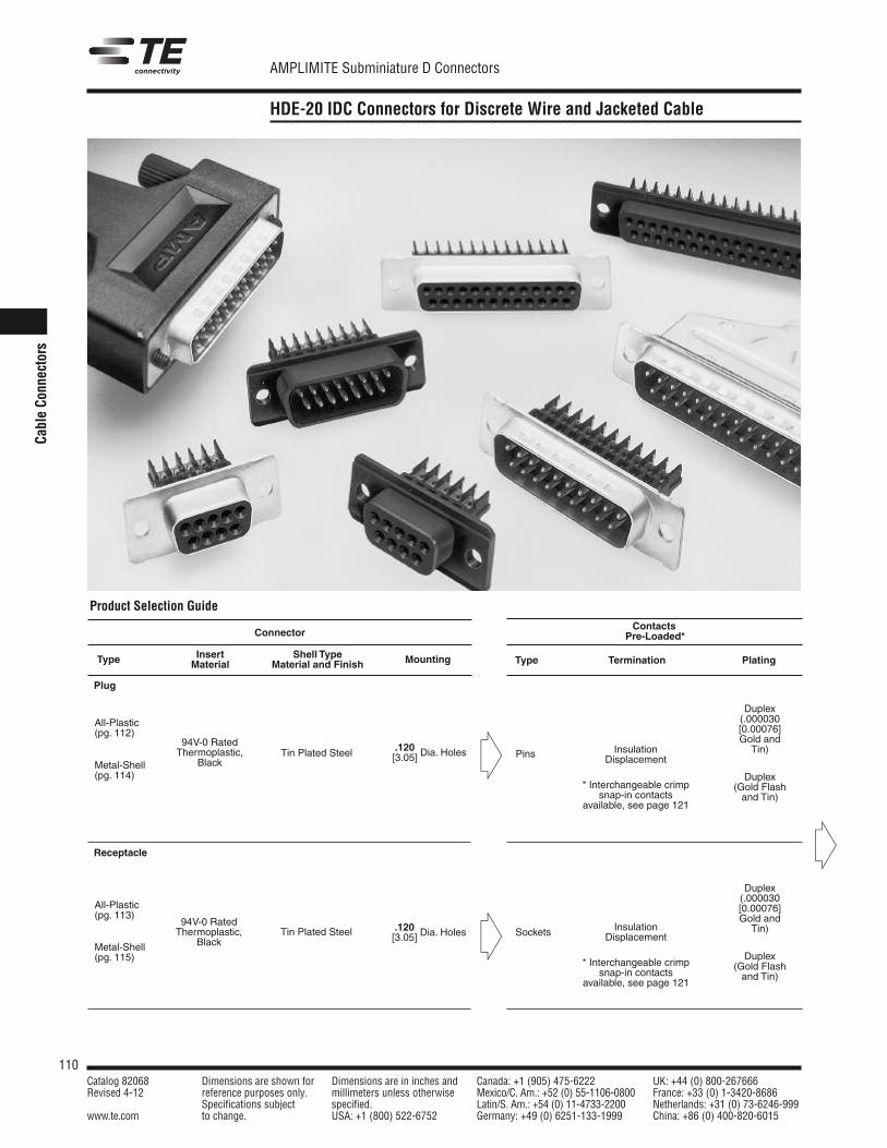
110Catalog 82068 Dimensions are shown for Dimensions are in inches and Canada: +1 (905) 475-6222 UK: +44 (0) 800-267666Revised 4-12 reference purposes only. millimeters unless otherwise Mexico/C. Am.: +52 (0) 55-1106-0800 France: +33 (0) 1-3420-8686
Specifications subject specified. Latin/S. Am.: +54 (0) 11-4733-2200 Netherlands: +31 (0) 73-6246-999www.te.com to change. USA: +1 (800) 522-6752 Germany: +49 (0) 6251-133-1999 China: +86 (0) 400-820-6015
AMPLIMITE Subminiature D Connectors
Cabl
eCo
nnec
tors
HDE-20 IDC Connectors for Discrete Wire and Jacketed Cable
Product Selection Guide
Connector
Insert Shell TypeType Material Material and Finish Mounting
94V-0 RatedThermoplastic,
Black
All-Plastic(pg. 112)
Metal-Shell(pg. 114)
Metal-Shell(pg. 115)
94V-0 RatedThermoplastic,
Black
All-Plastic(pg. 113)
Tin Plated Steel
Tin Plated Steel
.120[3.05] Dia. Holes
.120[3.05] Dia. Holes
ContactsPre-Loaded*
Type Termination Plating
Pins
Sockets
InsulationDisplacement
* Interchangeable crimpsnap-in contacts
available, see page 121
InsulationDisplacement
* Interchangeable crimpsnap-in contacts
available, see page 121
Duplex(.000030[0.00076]Gold andTin)
Duplex(Gold Flashand Tin)
Duplex(.000030[0.00076]Gold andTin)
Duplex(Gold Flashand Tin)
Receptacle
Plug
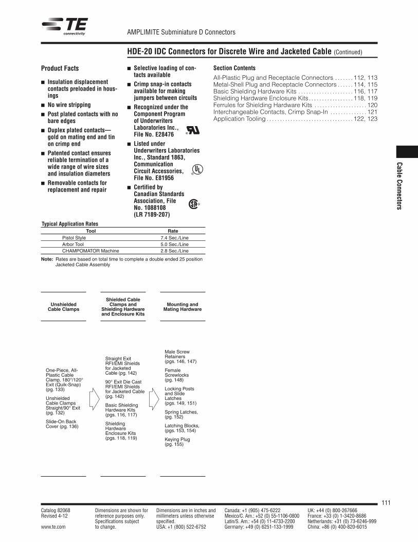
111Catalog 82068 Dimensions are shown for Dimensions are in inches and Canada: +1 (905) 475-6222 UK: +44 (0) 800-267666Revised 4-12 reference purposes only. millimeters unless otherwise Mexico/C. Am.: +52 (0) 55-1106-0800 France: +33 (0) 1-3420-8686
Specifications subject specified. Latin/S. Am.: +54 (0) 11-4733-2200 Netherlands: +31 (0) 73-6246-999www.te.com to change. USA: +1 (800) 522-6752 Germany: +49 (0) 6251-133-1999 China: +86 (0) 400-820-6015
AMPLIMITE Subminiature D Connectors
Cable Connectors
HDE-20 IDC Connectors for Discrete Wire and Jacketed Cable (Continued)
UnshieldedCable Clamps
One-Piece, All-Plastic CableClamp, 180°/120°Exit (Quik-Snap)(pg. 133)
UnshieldedCable ClampsStraight/90° Exit(pg. 132)
Slide-On BackCover (pg. 136)
Product Facts
Insulation displacementcontacts preloaded in hous-ings
No wire stripping
Post plated contacts with nobare edges
Duplex plated contacts—gold on mating end and tinon crimp end
Patented contact ensuresreliable termination of awide range of wire sizesand insulation diameters
Removable contacts forreplacement and repair
Selective loading of con-tacts available
Crimp snap-in contactsavailable for makingjumpers between circuits
Recognized under theComponent Programof UnderwritersLaboratories Inc.,File No. E28476
Listed underUnderwriters LaboratoriesInc., Standard 1863,Communication Circuit Accessories, File No. E81956
Certified byCanadian StandardsAssociation, FileNo. 1088108 (LR 7189-207)
Section Contents
All-Plastic Plug and Receptacle Connectors . . . . . . . 112, 113Metal-Shell Plug and Receptacle Connectors . . . . . . 114, 115Basic Shielding Hardware Kits . . . . . . . . . . . . . . . . . . . . . 116, 117Shielding Hardware Enclosure Kits. . . . . . . . . . . . . . . . . 118, 119Ferrules for Shielding Hardware Kits . . . . . . . . . . . . . . . . . . . . 120Interchangeable Contacts, Crimp Snap-In . . . . . . . . . . . . . . 121Application Tooling . . . . . . . . . . . . . . . . . . . . . . . . . . . . . . . . . 122, 123
Typical Application RatesTool Rate
Pistol Style 7.4 Sec./LineArbor Tool 5.0 Sec./LineCHAMPOMATOR Machine 2.8 Sec./Line
Note: Rates are based on total time to complete a double ended 25 positionJacketed Cable Assembly
R
R
Shielded CableClamps and
Shielding Hardwareand Enclosure Kits
Straight ExitRFI/EMI Shieldsfor JacketedCable (pg. 142)
90° Exit Die CastRFI/EMI Shieldsfor Jacketed Cable (pg. 142)
Basic ShieldingHardware Kits(pgs. 116, 117)
ShieldingHardwareEnclosure Kits(pgs. 118, 119)
Mounting andMating Hardware
Male ScrewRetainers(pgs. 146, 147)
FemaleScrewlocks(pg. 148)
Locking Postsand SlideLatches(pgs. 149, 151)
Spring Latches,(pg. 152)
Latching Blocks,(pgs. 153, 154)
Keying Plug(pg. 155)
R
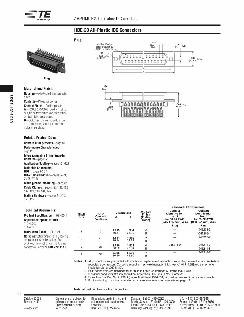
112Catalog 82068 Dimensions are shown for Dimensions are in inches and Canada: +1 (905) 475-6222 UK: +44 (0) 800-267666Revised 4-12 reference purposes only. millimeters unless otherwise Mexico/C. Am.: +52 (0) 55-1106-0800 France: +33 (0) 1-3420-8686
Specifications subject specified. Latin/S. Am.: +54 (0) 11-4733-2200 Netherlands: +31 (0) 73-6246-999www.te.com to change. USA: +1 (800) 522-6752 Germany: +49 (0) 6251-133-1999 China: +86 (0) 400-820-6015
AMPLIMITE Subminiature D Connectors
Note: All part numbers are RoHS compliant.
Cabl
e Co
nnec
tors
HDE-20 All-Plastic IDC Connectors
Notes: 1. All connectors are preloaded with insulation displacement contacts. Pins in plug connectors and sockets inreceptacle connectors. Contacts accept a max. wire insulation thickness of .015 [0.38] and a max. wireinsulation dia. of .060 [1.52].
Notes: 2. HDE connectors are designed for terminating solid or stranded (7-strand max.) wire.3. Individual conductor strands should be larger than .005 inch [0.127] diameter.4. Extraction Tool Part No. 91232-1 (Instruction Sheet 408-6631) is used to remove pin or socket contacts.5. For terminating more than one wire, or a drain wire, use crimp contacts on page 121.
Connector Part Numbers
Contact Contact ContactNo. of Identification IdentificationShellContact
Dimensions FinishNo. 1 No. 2Size
PositionsA B (Plating
for 30-26 AWG for 26-22 AWGCode)[0.05-0.15mm2] Wire [0.15-0.4mm2] Wire
Plug Plug
1.213 .984 A — 745203-21 9 30.81 24.99 B — 1-745203-1
1.541 1.312 A — 745207-72 15 39.14 33.33 B — —
2.090 1.852 A 745211-9 745211-73 25 53.09 47.04 B — 745211-8
2.732 2.500 A — 745215-74 37 69.39 63.50 B — —
Material and Finish:Housing—94V-0 rated thermoplastic,blackContacts—Phosphor bronzeContact Finish—Duplex plated:A—.000030 [0.00076] gold on matingend, tin on termination end, with entirecontact nickel underplatedB—Gold flash on mating end, tin on termination end, with entire contactnickel underplated
Related Product Data:Contact Arrangements—page 40Performance Characteristics—page 41Interchangeable Crimp Snap-InContacts—page 121Application Tooling—pages 121-123Mateable Connectors:HDP—pages 90-97HD-20 Board Mount—pages 54-71,78-85, 87-89Mating/Panel Mounting—page 42Cable Clamps—pages 132, 133, 135-137, 139, 140, 144, 145Mating Hardware—pages 146-150,153, 155
Technical Documents:Product Specification—108-40011Application Specifications—114-40002114-40003
Instruction Sheet—408-6621Note: Instruction Sheets for TE Toolingare packaged with the tooling. For additional information call the ToolingAssistance Center: 1-800-722-1111.
PlugMolded CavityIndentification & Trademark
.120 [3.05]2 Holes
.109[2.77]Ref.
BA
.112[2.85] Typ.
.509[12.93]
.860[21.84]
.230[5.84]
.080[2.03]
Max.
Dia.
Ref.
Plug
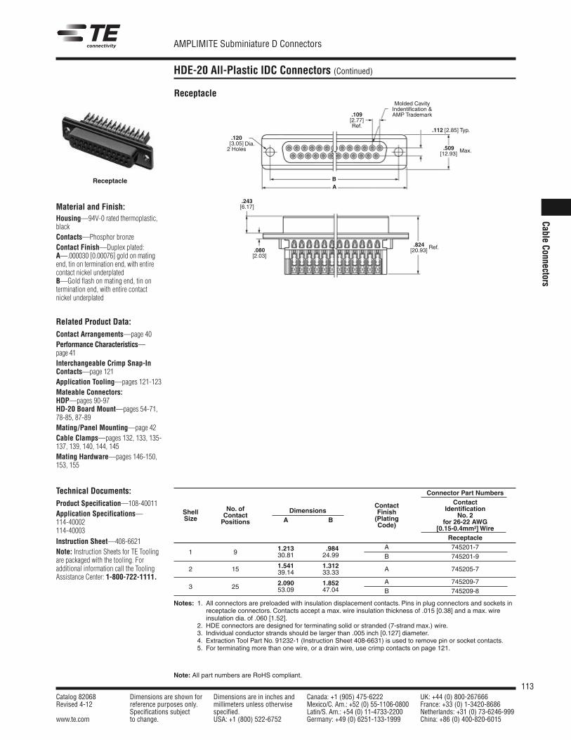
113Catalog 82068 Dimensions are shown for Dimensions are in inches and Canada: +1 (905) 475-6222 UK: +44 (0) 800-267666Revised 4-12 reference purposes only. millimeters unless otherwise Mexico/C. Am.: +52 (0) 55-1106-0800 France: +33 (0) 1-3420-8686
Specifications subject specified. Latin/S. Am.: +54 (0) 11-4733-2200 Netherlands: +31 (0) 73-6246-999www.te.com to change. USA: +1 (800) 522-6752 Germany: +49 (0) 6251-133-1999 China: +86 (0) 400-820-6015
AMPLIMITE Subminiature D Connectors
Note: All part numbers are RoHS compliant.
Cable Connectors
HDE-20 All-Plastic IDC Connectors (Continued)
Receptacle
Connector Part Numbers
Contact ContactNo. of IdentificationShell Contact
Dimensions Finish No. 2Size Positions A B (Plating for 26-22 AWGCode) [0.15-0.4mm2] WireReceptacle
1.213 .984 A 745201-71 9 30.81 24.99 B 745201-9
1.541 1.312 A 745205-72 15 39.14 33.33
2.090 1.852 A 745209-73 25 53.09 47.04 B 745209-8
Notes: 1. All connectors are preloaded with insulation displacement contacts. Pins in plug connectors and sockets inreceptacle connectors. Contacts accept a max. wire insulation thickness of .015 [0.38] and a max. wireinsulation dia. of .060 [1.52].
Notes: 2. HDE connectors are designed for terminating solid or stranded (7-strand max.) wire.3. Individual conductor strands should be larger than .005 inch [0.127] diameter.4. Extraction Tool Part No. 91232-1 (Instruction Sheet 408-6631) is used to remove pin or socket contacts.5. For terminating more than one wire, or a drain wire, use crimp contacts on page 121.
Molded CavityIndentification & Trademark
.243[6.17]
.120 [3.05]2 Holes
Dia.
.112 [2.85] Typ.
.509[12.93] Max.
.109[2.77]Ref.
BA
.824[20.93] Ref..080
[2.03]
Receptacle
Material and Finish:Housing—94V-0 rated thermoplastic,blackContacts—Phosphor bronzeContact Finish—Duplex plated:A—.000030 [0.00076] gold on matingend, tin on termination end, with entirecontact nickel underplatedB—Gold flash on mating end, tin on termination end, with entire contactnickel underplated
Related Product Data:Contact Arrangements—page 40Performance Characteristics—page 41Interchangeable Crimp Snap-InContacts—page 121Application Tooling—pages 121-123Mateable Connectors:HDP—pages 90-97HD-20 Board Mount—pages 54-71,78-85, 87-89Mating/Panel Mounting—page 42Cable Clamps—pages 132, 133, 135-137, 139, 140, 144, 145Mating Hardware—pages 146-150,153, 155
Technical Documents:Product Specification—108-40011Application Specifications—114-40002114-40003
Instruction Sheet—408-6621Note: Instruction Sheets for TE Toolingare packaged with the tooling. For additional information call the ToolingAssistance Center: 1-800-722-1111.
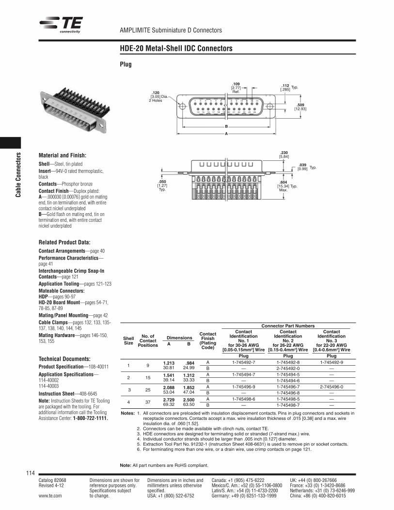
114Catalog 82068 Dimensions are shown for Dimensions are in inches and Canada: +1 (905) 475-6222 UK: +44 (0) 800-267666Revised 4-12 reference purposes only. millimeters unless otherwise Mexico/C. Am.: +52 (0) 55-1106-0800 France: +33 (0) 1-3420-8686
Specifications subject specified. Latin/S. Am.: +54 (0) 11-4733-2200 Netherlands: +31 (0) 73-6246-999www.te.com to change. USA: +1 (800) 522-6752 Germany: +49 (0) 6251-133-1999 China: +86 (0) 400-820-6015
AMPLIMITE Subminiature D Connectors
Note: All part numbers are RoHS compliant.
Cabl
e Co
nnec
tors
HDE-20 Metal-Shell IDC Connectors
Material and Finish:Shell—Steel, tin platedInsert—94V-0 rated thermoplastic,blackContacts—Phosphor bronzeContact Finish—Duplex plated:A—.000030 [0.00076] gold on matingend, tin on termination end, with entirecontact nickel underplatedB—Gold flash on mating end, tin on termination end, with entire contactnickel underplated
Related Product Data:Contact Arrangements—page 40Performance Characteristics—page 41Interchangeable Crimp Snap-InContacts—page 121Application Tooling—pages 121-123Mateable Connectors:HDP—pages 90-97HD-20 Board Mount—pages 54-71,78-85, 87-89Mating/Panel Mounting—page 42Cable Clamps—pages 132, 133, 135-137, 138, 140, 144, 145Mating Hardware—pages 146-150,153, 155
Technical Documents:Product Specification—108-40011
Application Specifications—114-40002114-40003
Instruction Sheet—408-6645Note: Instruction Sheets for TE Toolingare packaged with the tooling. For additional information call the ToolingAssistance Center: 1-800-722-1111.
Plug
A
B
.112[.285]
.509[12.93]
.050[1.27]Typ.
.039[0.99] Typ.
.604[15.34]Max.
Typ.
Typ..120 [3.05]2 Holes
Dia.
.109[2.77]Ref.
.230[5.84]
1.213 .984 A 1-745492-7 1-745492-8 1-745492-91 9 30.81 24.99 B — 2-745492-0 —
1.541 1.312 A 1-745494-7 1-745494-5 —2 15 39.14 33.33 B — 1-745494-6 —
2.088 1.852 A 1-745496-9 1-745496-7 2-745496-0*3 25 53.04 47.04 B — 1-745496-8 —
2.729 2.500 A 1-745498-6 1-745498-5 —4 37 69.32 63.50 B — 1-745498-7 —
Connector Part NumbersContact Contact Contact
Identification Identification IdentificationContact
No. 1 No. 2 No. 3No. of Finish
for 30-26 AWG for 26-22 AWG for 22-20 AWG
Shell ContactDimensions
(Plating
[0.05-0.15mm2] Wire [0.15-0.4mm2] Wire [0.4-0.6mm2] Wire
Size Positions A BCode)
Plug Plug Plug
Notes: 1. All connectors are preloaded with insulation displacement contacts. Pins in plug connectors and sockets inreceptacle connectors. Contacts accept a max. wire insulation thickness of .015 [0.38] and a max. wireinsulation dia. of .060 [1.52].
Notes: 2. Connectors can be made available with clinch nuts, contact TE.3. HDE connectors are designed for terminating solid or stranded (7-strand max.) wire.4. Individual conductor strands should be larger than .005 inch [0.127] diameter.5. Extraction Tool Part No. 91232-1 (Instruction Sheet 408-6631) is used to remove pin or socket contacts.6. For terminating more than one wire, or a drain wire, use crimp contacts on page 121.
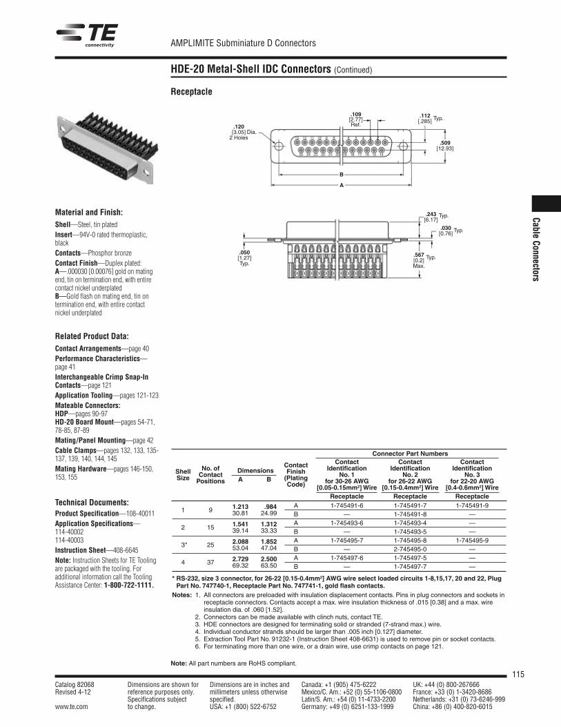
115Catalog 82068 Dimensions are shown for Dimensions are in inches and Canada: +1 (905) 475-6222 UK: +44 (0) 800-267666Revised 4-12 reference purposes only. millimeters unless otherwise Mexico/C. Am.: +52 (0) 55-1106-0800 France: +33 (0) 1-3420-8686
Specifications subject specified. Latin/S. Am.: +54 (0) 11-4733-2200 Netherlands: +31 (0) 73-6246-999www.te.com to change. USA: +1 (800) 522-6752 Germany: +49 (0) 6251-133-1999 China: +86 (0) 400-820-6015
AMPLIMITE Subminiature D Connectors
Note: All part numbers are RoHS compliant.
Cable Connectors
HDE-20 Metal-Shell IDC Connectors (Continued)
Material and Finish:Shell—Steel, tin platedInsert—94V-0 rated thermoplastic,blackContacts—Phosphor bronzeContact Finish—Duplex plated:A—.000030 [0.00076] gold on matingend, tin on termination end, with entirecontact nickel underplatedB—Gold flash on mating end, tin on termination end, with entire contactnickel underplated
Related Product Data:Contact Arrangements—page 40Performance Characteristics—page 41Interchangeable Crimp Snap-InContacts—page 121Application Tooling—pages 121-123Mateable Connectors:HDP—pages 90-97HD-20 Board Mount—pages 54-71,78-85, 87-89Mating/Panel Mounting—page 42Cable Clamps—pages 132, 133, 135-137, 139, 140, 144, 145Mating Hardware—pages 146-150,153, 155
Technical Documents:Product Specification—108-40011Application Specifications—114-40002114-40003Instruction Sheet—408-6645Note: Instruction Sheets for TE Toolingare packaged with the tooling. For additional information call the ToolingAssistance Center: 1-800-722-1111.
Receptacle
A
B
.109[2.77]Ref.
.112[.285]
.509[12.93]
.243[6.17]
.030[0.76] Typ.
.567[0.2]Max.
Typ.
Typ.
Typ.
.120 [3.05]2 Holes
Dia.
.050[1.27]Typ.
1.213 .984 A 1-745491-6 1-745491-7 1-745491-91 9 30.81 24.99 B — 1-745491-8 —
1.541 1.312 A 1-745493-6 1-745493-4 —2 15 39.14 33.33 B — 1-745493-5 —
2.088 1.852 A 1-745495-7 1-745495-8 1-745495-9*3* 25 53.04 47.04 B — 2-745495-0 —
2.729 2.500 A 1-745497-6 1-745497-5 —4 37 69.32 63.50 B — 1-745497-7 —
Connector Part NumbersContact Contact Contact
Identification Identification IdentificationContact
No. 1 No. 2 No. 3No. of Finish
for 30-26 AWG for 26-22 AWG for 22-20 AWG
Shell ContactDimensions
(Plating
[0.05-0.15mm2] Wire [0.15-0.4mm2] Wire [0.4-0.6mm2] Wire
Size Positions A BCode)
Receptacle Receptacle Receptacle
* RS-232, size 3 connector, for 26-22 [0.15-0.4mm2] AWG wire select loaded circuits 1-8,15,17, 20 and 22, PlugPart No. 747740-1, Receptacle Part No. 747741-1, gold flash contacts.
Notes: 1. All connectors are preloaded with insulation displacement contacts. Pins in plug connectors and sockets inreceptacle connectors. Contacts accept a max. wire insulation thickness of .015 [0.38] and a max. wireinsulation dia. of .060 [1.52].
Notes: 2. Connectors can be made available with clinch nuts, contact TE.3. HDE connectors are designed for terminating solid or stranded (7-strand max.) wire.4. Individual conductor strands should be larger than .005 inch [0.127] diameter.5. Extraction Tool Part No. 91232-1 (Instruction Sheet 408-6631) is used to remove pin or socket contacts.6. For terminating more than one wire, or a drain wire, use crimp contacts on page 121.
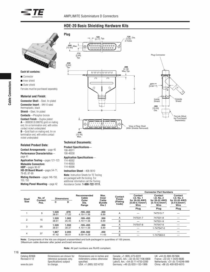
116Catalog 82068 Dimensions are shown for Dimensions are in inches and Canada: +1 (905) 475-6222 UK: +44 (0) 800-267666Revised 4-12 reference purposes only. millimeters unless otherwise Mexico/C. Am.: +52 (0) 55-1106-0800 France: +33 (0) 1-3420-8686
Specifications subject specified. Latin/S. Am.: +54 (0) 11-4733-2200 Netherlands: +31 (0) 73-6246-999www.te.com to change. USA: +1 (800) 522-6752 Germany: +49 (0) 6251-133-1999 China: +86 (0) 400-820-6015
AMPLIMITE Subminiature D Connectors
Note: All part numbers are RoHS compliant.
Cabl
e Co
nnec
tors
HDE-20 Basic Shielding Hardware Kits
Each kit contains:
Connector
Inner shield
Outer shield
Ferrules must be purchased separately.
Material and Finish:Connector Shell—Steel, tin platedConnector Insert—94V-0 rated thermoplastic, blackShield—Steel, tin platedContacts—Phosphor bronzeContact Finish—Duplex plated:A—.000030 [0.00076] gold on matingend, tin on termination end, with entirecontact nickel underplatedB—Gold flash on mating end, tin on termination end, with entire contactnickel underplated
Related Product Data:Contact Arrangements—page 40Performance Characteristics—page 41Application Tooling—pages 121-123Mateable Connectors:HDP—pages 90-97HD-20 Board Mount—pages 54-71,78-85, 87-89Mating Hardware—pages 146-150,153, 155Mating/Panel Mounting—page 42
Plug
.230[5.84]Typ. .086
[2.18]Max.Typ.
.509[12.93]
Max.
.112[2.84]Typ.
.109[2.77] Typ.
C
D
.490[12.45]Max.
View of Rear Shell(With Shields Removed)
Plug Connector
Ferrule (Mustbe PurchasedSeparately)
OutsideShield
InsideShield
.395[10.03]Dia.
.377±.015[9.58±0.38]
.120[3.05]2 Holes
Dia.
Connector Part NumbersRecommended Max. Contact Contact Contact
No. of Cable Inner Contact I.D. No. 1 I.D. No. 2 I.D. No. 3Shell ContactDimensions
Outer Cable Finish for 30-26 AWG for 26-22 AWG for 22-20 AWGSize Pos. C D Dia. Bundle (Plating [0.05-0.15mm2] [0.15-0.4mm2] [0.4-0.6mm2] Range Dia.† Code) Wire Wire Wire
Plug Plug Plug1.520 .678 .165-.455 .350 A — 747515-7 —1 9 38.61 17.22 4.19-11.56 8.89
1.520 1.002 .165-.455 .350 A 747531-7 747531-8 —2 15 38.61 25.45 4.19-11.56 8.89 B — 747531-9 —
1.520 1.550 .165-.455 .350 A 747547-8 747547-9 —3 25 38.61 39.37 4.19-11.56 8.89 B — 1-747547-0 —
1.867 2.205 .338-.562 .450 A — — —4 37 47.42 56.01 8.59-14.28 11.43 B — 1-747563-0 —
Note: Components of the kits are shipped unassembled and bulk-packaged in quantities of 100 pieces.†Maximum cable diameter after jacket and braid removed.
Technical Documents:
Product Specifications—108-40011108-40030
Application Specifications—114-40002114-40003114-40006
Instruction Sheet—408-9010
Note: Instruction Sheets for TE Toolingare packaged with the tooling. For additional information call the ToolingAssistance Center: 1-800-722-1111.
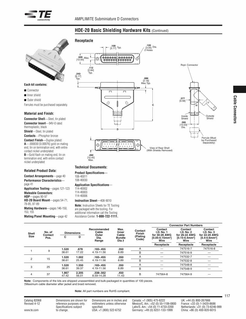
117Catalog 82068 Dimensions are shown for Dimensions are in inches and Canada: +1 (905) 475-6222 UK: +44 (0) 800-267666Revised 4-12 reference purposes only. millimeters unless otherwise Mexico/C. Am.: +52 (0) 55-1106-0800 France: +33 (0) 1-3420-8686
Specifications subject specified. Latin/S. Am.: +54 (0) 11-4733-2200 Netherlands: +31 (0) 73-6246-999www.te.com to change. USA: +1 (800) 522-6752 Germany: +49 (0) 6251-133-1999 China: +86 (0) 400-820-6015
AMPLIMITE Subminiature D Connectors
Note: All part numbers are RoHS compliant.
Cable Connectors
HDE-20 Basic Shielding Hardware Kits (Continued)
Each kit contains:
Connector
Inner shield
Outer shield
Ferrules must be purchased separately.
Material and Finish:Connector Shell—Steel, tin platedConnector Insert—94V-0 rated thermoplastic, blackShield—Steel, tin platedContacts—Phosphor bronzeContact Finish—Duplex plated:A—.000030 [0.00076] gold on matingend, tin on termination end, with entirecontact nickel underplatedB—Gold flash on mating end, tin on termination end, with entire contactnickel underplated
Related Product Data:Contact Arrangements—page 40Performance Characteristics—page 41Application Tooling—pages 121-123Mateable Connectors:HDP—pages 90-97HD-20 Board Mount—pages 54-71,78-85, 87-89Mating Hardware—pages 146-150,153, 155Mating/Panel Mounting—page 42
Receptacle
.243[6.17]Typ.
Rcpt. Connector
Ferrule (Mustbe PurchasedSeparately)
OutsideShield
InsideShield
View of Rear Shell(With Shields Removed)
.086[2.18]Max.Typ.
.509[12.93]
Max.
.112[2.84]Typ.
.109[2.77] Typ.
C
D
.490[12.45]Max.
.395[10.03]Dia.
.377[9.58]
.120[3.05]2 Holes
Dia.
Technical Documents:
Product Specifications—108-40011108-40030
Application Specifications—114-40002114-40003114-40006
Instruction Sheet—408-9010
Note: Instruction Sheets for TE Toolingare packaged with the tooling. For additional information call the ToolingAssistance Center: 1-800-722-1111.
Connector Part NumbersRecommended Max. Contact Contact Contact
No. of Cable Inner Contact I.D. No. 1 I.D. No. 2 I.D. No. 3Shell ContactDimensions
Outer Cable Finish for 30-26 AWG for 26-22 AWG for 22-20 AWGSize Pos. C D Dia. Bundle (Plating [0.05-0.15mm2] [0.15-0.4mm2] [0.4-0.6mm2] Range Dia.† Code) Wire Wire Wire
Receptacle Receptacle Receptacle
1.520 .678 .165-.455 .350 A — 747516-7 747516-81 9 38.61 17.22 4.19-11.56 8.89 B — 747516-9 —
1.520 1.002 .165-.455 .350 A — 747532-7 —2 15 38.61 25.45 4.19-11.56 8.89 B — 747532-8 —
1.520 1.550 .165-.455 .350 A — 747548-8 —3 25 38.61 39.37 4.19-11.56 8.89 B — 747548-9 —
1.867 2.205 .338-.562 .4504 37 47.42 56.01 8.59-14.28 11.43 B 747564-8 747564-9 —
Note: Components of the kits are shipped unassembled and bulk-packaged in quantities of 100 pieces.†Maximum cable diameter after jacket and braid removed.
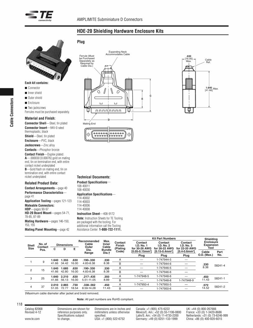
118Catalog 82068 Dimensions are shown for Dimensions are in inches and Canada: +1 (905) 475-6222 UK: +44 (0) 800-267666Revised 4-12 reference purposes only. millimeters unless otherwise Mexico/C. Am.: +52 (0) 55-1106-0800 France: +33 (0) 1-3420-8686
Specifications subject specified. Latin/S. Am.: +54 (0) 11-4733-2200 Netherlands: +31 (0) 73-6246-999www.te.com to change. USA: +1 (800) 522-6752 Germany: +49 (0) 6251-133-1999 China: +86 (0) 400-820-6015
AMPLIMITE Subminiature D Connectors
Note: All part numbers are RoHS compliant.
Cabl
e Co
nnec
tors
HDE-20 Shielding Hardware Enclosure Kits
Plug
Each kit contains:
Connector
Inner shield
Outer shield
Enclosure
Two jackscrewsFerrules must be purchased separately.
Material and Finish:Connector Shell—Steel, tin platedConnector Insert—94V-0 rated thermoplastic, blackShield—Steel, tin platedEnclosure—PVC, blackJackscrews—Zinc alloyContacts—Phosphor bronzeContact Finish—Duplex plated:A—.000030 [0.00076] gold on matingend, tin on termination end, with entirecontact nickel underplatedB—Gold flash on mating end, tin on termination end, with entire contactnickel underplated
Related Product Data:Contact Arrangements—page 40Performance Characteristics—page 41Application Tooling—pages 121-123Mateable Connectors:HDP—pages 90-97HD-20 Board Mount—pages 54-71,78-85, 87-89Mating Hardware—pages 146-150,153, 155Mating/Panel Mounting—page 42
D
EC
Mating End
Ferrule (Mustbe PurchasedSeparately asRequired byCable Dia.)
Expanding Neck Accommodates Cable
1.640[41.66]
Max.
CableRef.
.630[16.00]Max.
Kit Part Numbers ShieldingRecommended Max. Contact Contact Contact Contact Enclosure
Shell No. of Dimensions Cable Inner Finish I.D. No. 1 I.D. No. 2 I.D. No. 3 ExpansionSize Contact Outer Cable (Plating for 30-26 AWG for 26-22 AWG for 22-20 AWG Tool
Pos. C D E Dia. Bundle Code) [0.05-0.15mm2] [0.15-0.4mm2] [0.4-0.6mm2] Cable PartRange Dia.†Plug Plug Plug O.D. (Max.) No.
1.640 1.355 .630 .190-.330 .330 A — 1-747944-5 —1 9 41.66 34.42 16.00 4.83-8.38 8.38 B — 1-747944-6 — .330 58241-4
1.640 1.685 .630 .190-.330 .330 A — 1-747946-5 — 8.382 15 41.66 42.80 16.00 4.83-8.38 8.38 B — 1-747946-6 —
1.640 2.210 .630 .217-.435 .350 A 1-747948-5 1-747948-6 — .450 58241-13 25 41.66 56.13 16.00 5.51-11.05 8.89 B — 1-747948-8 1-747948-9 11.43
2.010 2.865 .730 .338-.562 .450 A 1-747950-4 1-747950-5 — .572 58241-24 37 51.05 72.77 18.54 8.59-14.28 11.43 B — 1-747950-6 — 14.52
†Maximum cable diameter after jacket and braid removed.
Technical Documents:Product Specifications—108-40011108-40030Application Specifications—114-40002114-40003114-40006114-40008Instruction Sheet—408-9172Note: Instruction Sheets for TE Toolingare packaged with the tooling. For additional information call the ToolingAssistance Center: 1-800-722-1111.
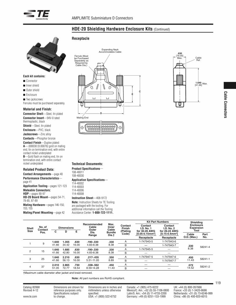
119Catalog 82068 Dimensions are shown for Dimensions are in inches and Canada: +1 (905) 475-6222 UK: +44 (0) 800-267666Revised 4-12 reference purposes only. millimeters unless otherwise Mexico/C. Am.: +52 (0) 55-1106-0800 France: +33 (0) 1-3420-8686
Specifications subject specified. Latin/S. Am.: +54 (0) 11-4733-2200 Netherlands: +31 (0) 73-6246-999www.te.com to change. USA: +1 (800) 522-6752 Germany: +49 (0) 6251-133-1999 China: +86 (0) 400-820-6015
AMPLIMITE Subminiature D Connectors
Note: All part numbers are RoHS compliant.
Cable Connectors
HDE-20 Shielding Hardware Enclosure Kits (Continued)
Receptacle
Mating End
Ferrule (Mustbe PurchasedSeparately asRequired byCable Dia.)
Expanding Neck Accommodates Cable
CableRef.
D
EC
1.640[41.66]
Max.
.630[16.00]Max.
Kit Part Numbers ShieldingRecommended Max. Contact Contact Contact Enclosure
Shell No. of Dimensions Cable Inner Finish I.D. No. 1 I.D. No. 2 ExpansionSize Contact
C D EOuter Cable (Plating for 30-26 AWG for 26-22 AWG Tool
Pos. Dia. Bundle Code) [0.05-0.15mm2] [0.15-0.4mm2] Cable PartRange Dia.†Receptacle Receptacle O.D. (Max.) No.
1.640 1.355 .630 .190-.330 .330 A 1-747943-5 1-747943-61 9 41.66 34.42 16.00 4.83-8.38 8.38 B — 1-747943-7 .330 58241-4
1.640 1.685 .630 .190-.330 .330 A 1-747945-5 — 8.382 15 41.66 42.80 16.00 4.83-8.38 8.38 B — —
1.640 2.210 .630 .217-.435 .350 A 1-747947-5 1-747947-6 .450 58241-13 25 41.66 56.13 16.00 5.51-11.05 8.89 B — 1-747947-7 11.43
2.010 2.865 .730 .338-.562 .450 A — — .572 58241-24 37 51.05 72.77 18.54 8.59-14.28 11.43 B — — 14.52
†Maximum cable diameter after jacket and braid removed.
Each kit contains:
Connector
Inner shield
Outer shield
Enclosure
Two jackscrewsFerrules must be purchased separately.
Material and Finish:Connector Shell—Steel, tin platedConnector Insert—94V-0 rated thermoplastic, blackShield—Steel, tin platedEnclosure—PVC, blackJackscrews—Zinc alloyContacts—Phosphor bronzeContact Finish—Duplex plated:A—.000030 [0.00076] gold on matingend, tin on termination end, with entirecontact nickel underplatedB—Gold flash on mating end, tin on termination end, with entire contactnickel underplated
Related Product Data:Contact Arrangements—page 40Performance Characteristics—page 41Application Tooling—pages 121-123Mateable Connectors:HDP—pages 90-97HD-20 Board Mount—pages 54-71,78-85, 87-89Mating Hardware—pages 146-150,153, 155Mating/Panel Mounting—page 42
Technical Documents:Product Specifications—108-40011108-40030Application Specifications—114-40002114-40003114-40006114-40008Instruction Sheet—408-9172Note: Instruction Sheets for TE Toolingare packaged with the tooling. For additional information call the ToolingAssistance Center: 1-800-722-1111.

120Catalog 82068 Dimensions are shown for Dimensions are in inches and Canada: +1 (905) 475-6222 UK: +44 (0) 800-267666Revised 4-12 reference purposes only. millimeters unless otherwise Mexico/C. Am.: +52 (0) 55-1106-0800 France: +33 (0) 1-3420-8686
Specifications subject specified. Latin/S. Am.: +54 (0) 11-4733-2200 Netherlands: +31 (0) 73-6246-999www.te.com to change. USA: +1 (800) 522-6752 Germany: +49 (0) 6251-133-1999 China: +86 (0) 400-820-6015
AMPLIMITE Subminiature D Connectors
Note: All part numbers are RoHS compliant.
Cabl
e Co
nnec
tors
HDE-20 Crimp Snap-In Contact Connectors
Shell L Cable Part NumbersSizes Style Dim. Diameter Ferrule Die Sets*
.440 .165-.1901-3 Stepped 11.18 4.19-4.83 3-747579-0 543424-3
.440 .190-.2171-3 Stepped 11.18 4.83-5.51 3-747579-0 543424-2
.440 .217-.2461-3 Stepped 11.18 5.51-6.25 3-747579-0 543424-8
.440 .246-.2841-3 Stepped 11.18 6.25-7.21 3-747579-2 543424-1
.440 .284-.3241-3 Stepped 11.18 7.21-8.23 3-747579-2 543424-7
.440 .324-.3751-3 Stepped 11.18 8.23-9.53 3-747579-4 543424-6
.440 .375-.4351-3 Straight 11.18 9.53-11.05 2-747579-7 543424-5
.440 .400-.4551-3 Straight 11.18 10.16-11.56 3-747579-6 543424-4
.625 .230-.2654 Stepped 15.88 5.84-6.73 2-747580-4 543425-2
.625 .338-.3854 Stepped 15.88 8.59-9.78 2-747580-3 543425-1
.625 .375-4324 Stepped 15.88 9.53-10.97 2-747580-1 58238-1
.625 .422-.4904 Stepped 15.88 10.72-12.45 3-747580-1 58237-2
.625 .480-.5624 Straight 15.88 12.19-14.28 2-747580-2 58237-1
Material and Finish:Steel (annealed), tin plated
Related Product Data:Shielding Hardware andEnclosure Kits—pages 116-119
Technical Documents:
Instruction Sheets—408-9242408-9243408-9507408-9508
Note: Instruction Sheets for TE Toolingare packaged with the tooling. For additional information call the ToolingAssistance Center: 1-800-722-1111.
Application Tooling forShielding Hardware Kits
Hand Crimping ToolNo. 543344-1
(Requires Die Sets, seetable above.)
Pneumatic Bench ToolNo. 312522-3
(Requires Die Set HolderNo. 58449-1.)
*Die sets used with Hand Crimping Tool Part No. 543344-1 or PneumaticBench Tool Part No. 312522-3 equipped with Die Set Holder Part No. 58449-1.
L
.020[0.51]
Ferrules forShielding Hardware Kits
Stepped
Straight
Shielding EnclosureExpansion Tools
Part No. 58241-1 (.450 [11.43])†Part No. 58241-2 (.572 [14.53])†Part No. 58241-4 (.330 [8.38])†0†Maximum Cable Diameter
(Instruction Sheet—408-9507)
BenchMountingPlate
Part No. 313183-1
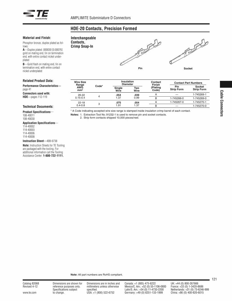
121Catalog 82068 Dimensions are shown for Dimensions are in inches and Canada: +1 (905) 475-6222 UK: +44 (0) 800-267666Revised 4-12 reference purposes only. millimeters unless otherwise Mexico/C. Am.: +52 (0) 55-1106-0800 France: +33 (0) 1-3420-8686
Specifications subject specified. Latin/S. Am.: +54 (0) 11-4733-2200 Netherlands: +31 (0) 73-6246-999www.te.com to change. USA: +1 (800) 522-6752 Germany: +49 (0) 6251-133-1999 China: +86 (0) 400-820-6015
AMPLIMITE Subminiature D Connectors
Note: All part numbers are RoHS compliant.
Cable Connectors
HDE-20 Contacts, Precision Formed
Material and Finish:Phosphor bronze, duplex plated as fol-lows:A—Duplex plated .000030 [0.00076]gold on mating end, tin on terminationend, with entire contact nickel under-platedB—Gold flash on mating end, tin on termination end, with entire contactnickel underplated
Related Product Data:Performance Characteristics—page 41Connectors used with:HDE—pages 112-119
Technical Documents:
Product Specifications—108-40011108-40030Application Specifications—114-40002114-40003114-40006114-40008Instruction Sheet—408-6738
Note: Instruction Sheets for TE Toolingare packaged with the tooling. For additional information call the ToolingAssistance Center: 1-800-722-1111.
InterchangeableContacts,Crimp Snap-In
Pin Socket
Wire Size Insulation ContactRange Diameter Finish
Contact Part Numbers
AWG Code*Single Two (Plating Pin Socket
mm2 Wire Wire Code) Strip Form Strip Form
26-22 .054 .039 A — 1-745269-10.15-0.4 4 1.37 0.99 B 1-745266-0 1-745269-0
22-18 .075 .054 A 1-745267-0 1-745270-10.4-0.8 3 1.91 1.37 B — 1-745270-0
* A Code indicating accepted wire size range is stamped inside insulation crimp barrel of each contact.Notes: 1. Extraction Tool No. 91232-1 is used to remove pin and socket contacts.
2. Strip form contacts shipped 10,000 pieces/reel.
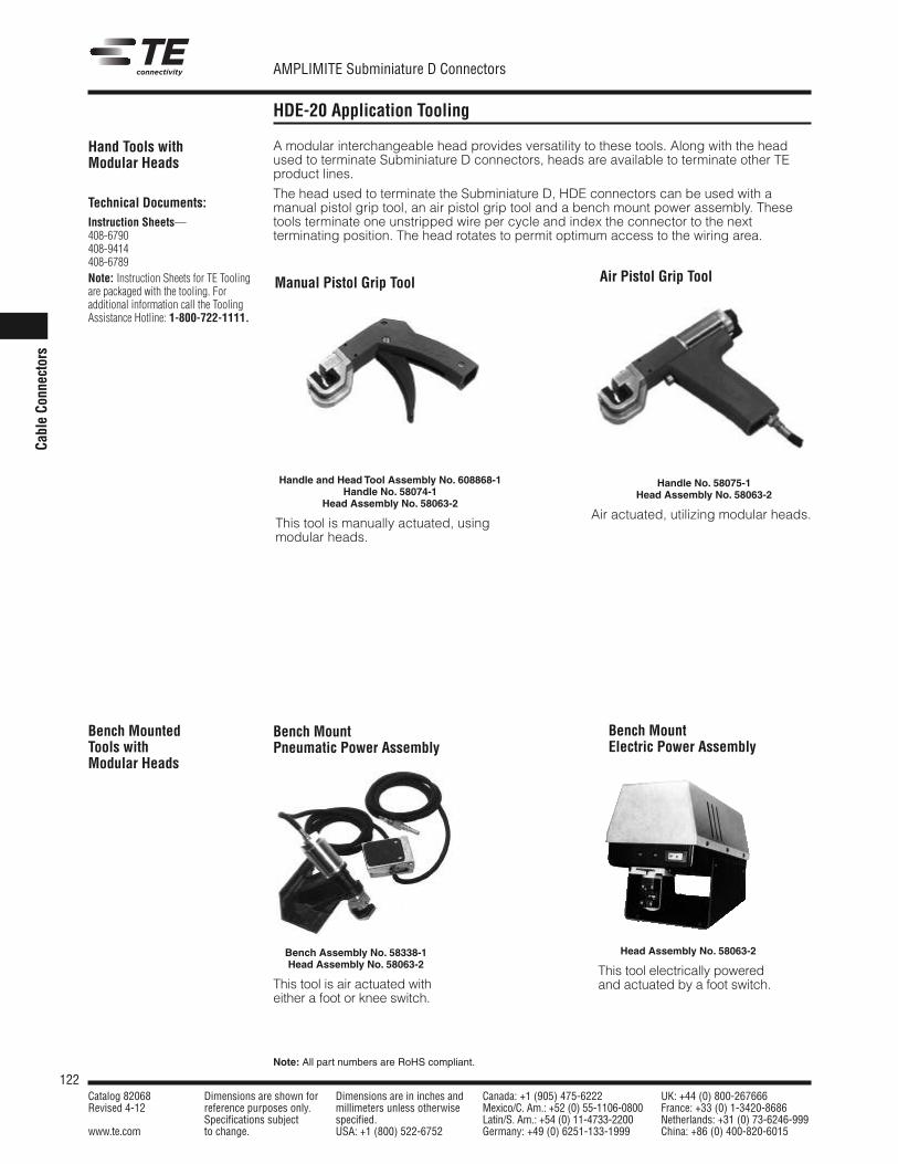
122Catalog 82068 Dimensions are shown for Dimensions are in inches and Canada: +1 (905) 475-6222 UK: +44 (0) 800-267666Revised 4-12 reference purposes only. millimeters unless otherwise Mexico/C. Am.: +52 (0) 55-1106-0800 France: +33 (0) 1-3420-8686
Specifications subject specified. Latin/S. Am.: +54 (0) 11-4733-2200 Netherlands: +31 (0) 73-6246-999www.te.com to change. USA: +1 (800) 522-6752 Germany: +49 (0) 6251-133-1999 China: +86 (0) 400-820-6015
AMPLIMITE Subminiature D Connectors
Note: All part numbers are RoHS compliant.
Cabl
e Co
nnec
tors
HDE-20 Application Tooling
A modular interchangeable head provides versatility to these tools. Along with the headused to terminate Subminiature D connectors, heads are available to terminate other TEproduct lines.
The head used to terminate the Subminiature D, HDE connectors can be used with amanual pistol grip tool, an air pistol grip tool and a bench mount power assembly. Thesetools terminate one unstripped wire per cycle and index the connector to the nextterminating position. The head rotates to permit optimum access to the wiring area.
Hand Tools withModular Heads
Technical Documents:Instruction Sheets—408-6790408-9414408-6789Note: Instruction Sheets for TE Toolingare packaged with the tooling. For additional information call the ToolingAssistance Hotline: 1-800-722-1111.
Handle and Head Tool Assembly No. 608868-1Handle No. 58074-1
Head Assembly No. 58063-2
This tool is manually actuated, usingmodular heads.
Bench MountPneumatic Power Assembly
Bench MountElectric Power Assembly
Bench Assembly No. 58338-1Head Assembly No. 58063-2
This tool is air actuated witheither a foot or knee switch.
Head Assembly No. 58063-2
This tool electrically poweredand actuated by a foot switch.
Manual Pistol Grip Tool Air Pistol Grip Tool
Handle No. 58075-1Head Assembly No. 58063-2
Air actuated, utilizing modular heads.
Bench MountedTools withModular Heads
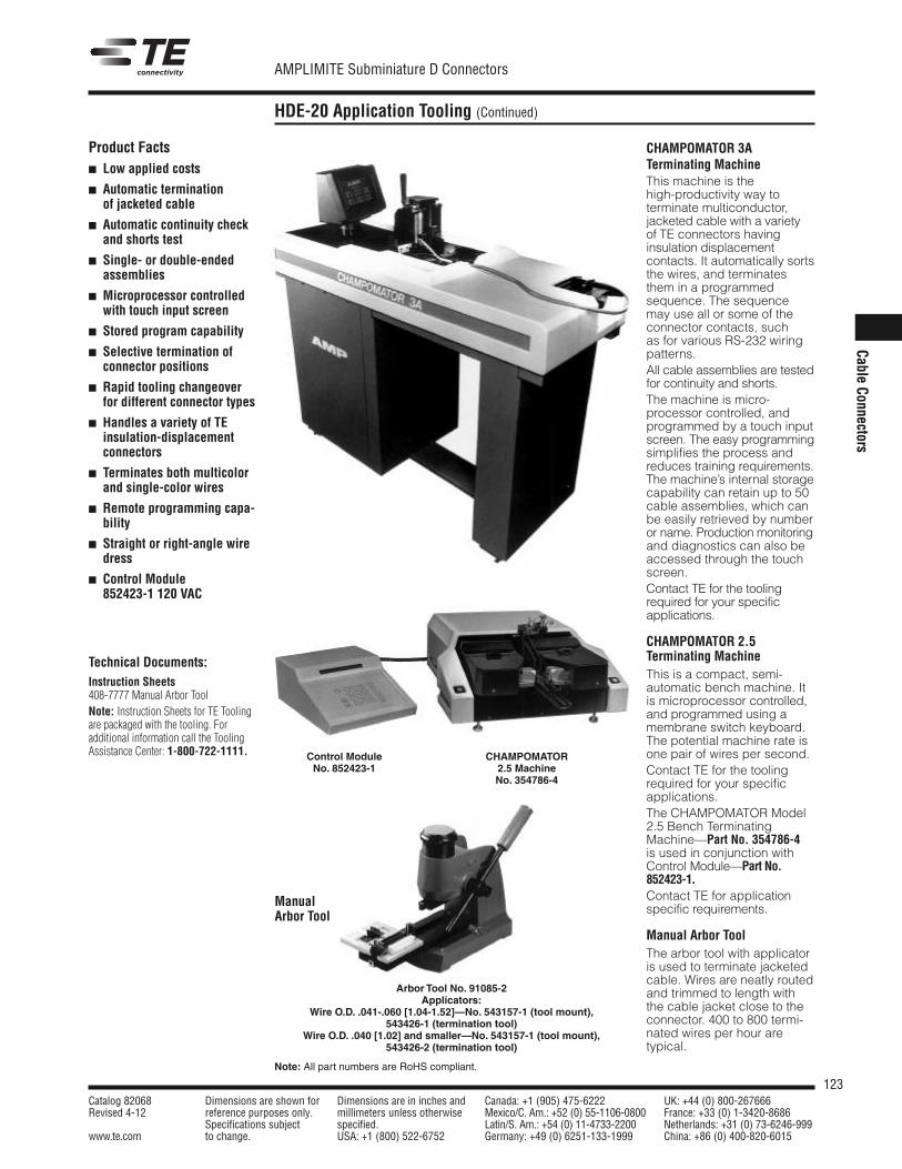
123Catalog 82068 Dimensions are shown for Dimensions are in inches and Canada: +1 (905) 475-6222 UK: +44 (0) 800-267666Revised 4-12 reference purposes only. millimeters unless otherwise Mexico/C. Am.: +52 (0) 55-1106-0800 France: +33 (0) 1-3420-8686
Specifications subject specified. Latin/S. Am.: +54 (0) 11-4733-2200 Netherlands: +31 (0) 73-6246-999www.te.com to change. USA: +1 (800) 522-6752 Germany: +49 (0) 6251-133-1999 China: +86 (0) 400-820-6015
AMPLIMITE Subminiature D Connectors
Note: All part numbers are RoHS compliant.
Cable Connectors
HDE-20 Application Tooling (Continued)
CHAMPOMATOR 3ATerminating MachineThis machine is the high-productivity way to terminate multiconductor, jacketed cable with a variety of TE connectors havinginsulation displacementcontacts. It automatically sortsthe wires, and terminatesthem in a programmedsequence. The sequencemay use all or some of theconnector contacts, such as for various RS-232 wiringpatterns.All cable assemblies are testedfor continuity and shorts.The machine is micro-processor controlled, andprogrammed by a touch inputscreen. The easy programmingsimplifies the process andreduces training require ments.The machine’s internal storagecapability can retain up to 50cable assemblies, which canbe easily retrieved by numberor name. Produc tion monitoringand diag nostics can also beaccessed through the touchscreen.Contact TE for the toolingrequired for your specificapplications.
CHAMPOMATOR 2.5Terminating MachineThis is a compact, semi-automatic bench machine. Itis microprocessor controlled,and programmed using amembrane switch keyboard.The potential machine rate isone pair of wires per second.Contact TE for the toolingrequired for your specificapplications.The CHAMPOMATOR Model2.5 Bench TerminatingMachine—Part No. 354786-4is used in conjunction withControl Module—Part No.852423-1.Contact TE for applicationspecific requirements.
Manual Arbor ToolThe arbor tool with applicatoris used to terminate jacketedcable. Wires are neatly routedand trimmed to length withthe cable jacket close to theconnector. 400 to 800 termi -nated wires per hour are typical.
ManualArbor Tool
Arbor Tool No. 91085-2Applicators:
Wire O.D. .041-.060 [1.04-1.52]—No. 543157-1 (tool mount),543426-1 (termination tool)
Wire O.D. .040 [1.02] and smaller—No. 543157-1 (tool mount),543426-2 (termination tool)
Control ModuleNo. 852423-1
CHAMPOMATOR2.5 MachineNo. 354786-4
Product Facts Low applied costs
Automatic termination of jacketed cable
Automatic continuity checkand shorts test
Single- or double-endedassemblies
Microprocessor controlledwith touch input screen
Stored program capability
Selective termination ofconnector positions
Rapid tooling changeoverfor different connector types
Handles a variety of TEinsulation-displacementconnectors
Terminates both multicolorand single-color wires
Remote programming capa-bility
Straight or right-angle wiredress
Control Module852423-1 120 VAC
Technical Documents:Instruction Sheets408-7777 Manual Arbor ToolNote: Instruction Sheets for TE Toolingare packaged with the tooling. For additional information call the ToolingAssistance Center: 1-800-722-1111.
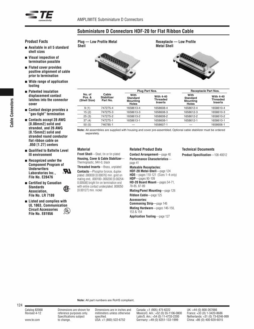
124Catalog 82068 Dimensions are shown for Dimensions are in inches and Canada: +1 (905) 475-6222 UK: +44 (0) 800-267666Revised 4-12 reference purposes only. millimeters unless otherwise Mexico/C. Am.: +52 (0) 55-1106-0800 France: +33 (0) 1-3420-8686
Specifications subject specified. Latin/S. Am.: +54 (0) 11-4733-2200 Netherlands: +31 (0) 73-6246-999www.te.com to change. USA: +1 (800) 522-6752 Germany: +49 (0) 6251-133-1999 China: +86 (0) 400-820-6015
AMPLIMITE Subminiature D Connectors
Note: All part numbers are RoHS compliant.
Cabl
e Co
nnec
tors
Subminiature D Connectors HDF-20 for Flat Ribbon Cable
Related Product DataContact Arrangement—page 40Performance Characteristics—page 41Mateable Receptacles:HDF-20 Metal-Shell—page 124HDE—pages 110-121 (Sizes 1–4 only)HDP—pages 90-109HD-20 Board Mount—pages 54-71,78-85, 87-89Mating/Panel Mounting—page 126Ribbon Cable—page 125Accessories:Commoning Strip—page 146Mating Hardware—pages 146-150,153 & 154Application Tooling—page 127
Technical DocumentsProduct Specification—108-40012
Product Facts Available in all 5 standard shell sizes
Visual inspection oftermination possible
Fluted cover providespositive alignment of cableprior to termination
Wide range of applicationtooling
Patented insulationdisplacement contactlatches into the connectorcover
Contact design provides a“gas-tight” termination
Contacts accept 28 AWG[0.08mm2] solid andstranded, and 26 AWG[0.15mm2] solid andstranded round conductorflat ribbon cable on .050 [1.27] centers
Qualified to Battelle LevelIII environment
Recognized under theComponent Program ofUnderwriters Laboratories Inc.,File No. E28476
Certified by CanadianStandards Association, File No. LR 7189
Listed and complies with UL 1863, CommunicationCircuit AccessoriesFile No. E81956 R
R
R
Plug — Low Profile MetalShell
Receptacle — Low ProfileMetal Shell
Plug Part Nos. Receptacle Part Nos.No. of Cable With WithPos. & Stabilizer Standard With 4-40 Standard With 4-40
(Shell Size) Part No. Mounting Threaded Mounting Threaded
Holes Inserts Holes Inserts
9 (1) 747275-4 1658613-4 1658608-4 1658612-4 1658610-415 (2) 747275-3 1658613-3 1658608-3 1658612-3 1658610-325 (3) 747275-2 1658613-2 1658608-2 1658612-2 1658610-237 (4) 747275-1 1658613-1 1658608-1 1658612-1 1658610-150 (5) 746785-1 — 1658607-1 — 1658606-1
Note: All assemblies are supplied with housing and cover pre-assembled. Optional cable stabilizer must be orderedseparately.
MaterialFront Shell—Steel, tin or tin platedHousing, Cover & Cable Stabilizer—Thermoplastic, 94V-0, blackThreaded Inserts—Brass, unplatedContacts—Phosphor bronze, duplexplated .000030 [0.00076] min. gold onmating end, .000100-.000200 [0.00254-0.00508] bright tin on termination endwith entire contact underplated .000050[0.00127] min. nickel
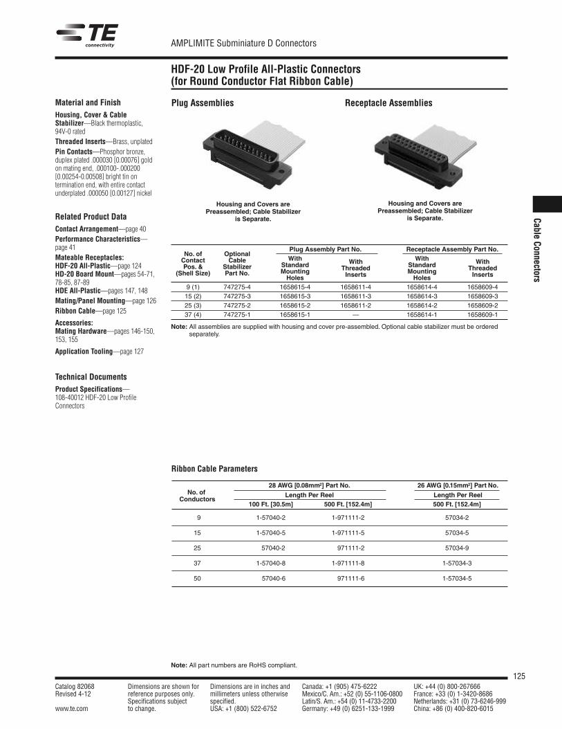
125Catalog 82068 Dimensions are shown for Dimensions are in inches and Canada: +1 (905) 475-6222 UK: +44 (0) 800-267666Revised 4-12 reference purposes only. millimeters unless otherwise Mexico/C. Am.: +52 (0) 55-1106-0800 France: +33 (0) 1-3420-8686
Specifications subject specified. Latin/S. Am.: +54 (0) 11-4733-2200 Netherlands: +31 (0) 73-6246-999www.te.com to change. USA: +1 (800) 522-6752 Germany: +49 (0) 6251-133-1999 China: +86 (0) 400-820-6015
AMPLIMITE Subminiature D Connectors
Note: All part numbers are RoHS compliant.
Cable Connectors
HDF-20 Low Profile All-Plastic Connectors (for Round Conductor Flat Ribbon Cable)
Plug AssembliesMaterial and FinishHousing, Cover & CableStabilizer—Black thermoplastic,94V-0 ratedThreaded Inserts—Brass, unplatedPin Contacts—Phosphor bronze,duplex plated .000030 [0.00076] goldon mating end, .000100-.000200[0.00254-0.00508] bright tin on termination end, with entire contactunderplated .000050 [0.00127] nickel
Related Product DataContact Arrangement—page 40Performance Characteristics—page 41Mateable Receptacles:HDF-20 All-Plastic—page 124HD-20 Board Mount—pages 54-71,78-85, 87-89HDE All-Plastic—pages 147, 148Mating/Panel Mounting—page 126Ribbon Cable—page 125
Accessories:Mating Hardware—pages 146-150,153, 155
Application Tooling—page 127
Technical DocumentsProduct Specifications—108-40012 HDF-20 Low ProfileConnectors
Housing and Covers arePreassembled; Cable Stabilizer
is Separate.
Receptacle Assemblies
Housing and Covers arePreassembled; Cable Stabilizer
is Separate.
Plug Assembly Part No. Receptacle Assembly Part No.No. of Optional
With WithContact CableStandard With Standard With
Pos. & StabilizerMounting Threaded Mounting Threaded
(Shell Size) Part No.Holes Inserts Holes Inserts
9 (1) 747275-4 1658615-4 1658611-4 1658614-4 1658609-415 (2) 747275-3 1658615-3 1658611-3 1658614-3 1658609-325 (3) 747275-2 1658615-2 1658611-2 1658614-2 1658609-237 (4) 747275-1 1658615-1 — 1658614-1 1658609-1
Note: All assemblies are supplied with housing and cover pre-assembled. Optional cable stabilizer must be orderedseparately.
Ribbon Cable Parameters
28 AWG [0.08mm2] Part No. 26 AWG [0.15mm2] Part No.No. of Length Per Reel Length Per Reel
Conductors100 Ft. [30.5m] 500 Ft. [152.4m] 500 Ft. [152.4m]
9 1-57040-2 1-971111-2 57034-2
15 1-57040-5 1-971111-5 57034-5
25 57040-2 1-971111-2 57034-9
37 1-57040-8 1-971111-8 1-57034-3
50 1-57040-6 1-971111-6 1-57034-5
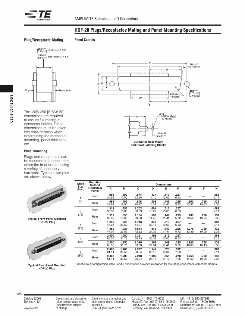
126Catalog 82068 Dimensions are shown for Dimensions are in inches and Canada: +1 (905) 475-6222 UK: +44 (0) 800-267666Revised 4-12 reference purposes only. millimeters unless otherwise Mexico/C. Am.: +52 (0) 55-1106-0800 France: +33 (0) 1-3420-8686
Specifications subject specified. Latin/S. Am.: +54 (0) 11-4733-2200 Netherlands: +31 (0) 73-6246-999www.te.com to change. USA: +1 (800) 522-6752 Germany: +49 (0) 6251-133-1999 China: +86 (0) 400-820-6015
AMPLIMITE Subminiature D Connectors
Cabl
e Co
nnec
tors
HDF-20 Plugs/Receptacles Mating and Panel Mounting Specifications
Plug/Receptacle Mating
The .265/.256 [6.73/6.50]dimensions are required to assure full mating ofconnector halves. Thesedimensions must be takeninto consideration whendetermining the method ofmounting, panel thickness,etc.
Panel Mounting
Plugs and receptacles canbe mounted to a panel fromeither the front or rear, usinga variety of accessoryhardware. Typical examplesare shown below.
Typical Front-Panel Mounted HDF-20 Plug
Typical Rear-Panel Mounted HDF-20 Plug
Panel Cutouts
Cutout for Rear Mountand Short Latching Blocks
CD
E
H*
J*
A
F
B
ReceptaclePlug
K Radius(4 Places)
10° ± 2°(2 Places)
.120± .002[3.05± 0.05 ] (2 Places)
.040[1.02] Dia. (Typ.)(2 Holes)
.129± .002[3.28± 0.05]
.265±.015[6.73±0.38] Shell Sizes 1 & 2
.256±.015[6.50±0.38] Shell Sizes 3, 4 & 5
A
CL
Shell Mounting
Size Method Dimensions
(Pos.) Front/Rear A B C D E F *H* *J* KPanel
.984 .492 .874 .437 .513 .257 .0831
Front 24.99 12.50 22.20 11.10 13.03 6.53 — — 2.11(9) .984 .492 .806 .403 .449 .225 .550 .750 .132Rear 24.99 12.50 20.47 10.24 11.41 5.72 13.97 19.05 3.35
1.312 .656 1.202 .601 .513 .257 .0832
Front 33.33 16.66 30.53 15.27 13.03 6.53 — — 2.11(15) 1.312 .656 1.134 .567 .449 .225 .730 .750 .132Rear 33.33 16.66 28.80 14.40 11.41 5.72 18.54 19.05 3.35
1.852 .926 1.743 .872 .513 .257 .0833
Front 47.04 23.52 44.27 22.15 13.03 6.53 — — 2.11(25) 1.852 .926 1.674 .842 .449 .225 1.275 .750 .132Rear 47.04 23.52 42.52 21.39 11.41 5.72 32.39 19.05 3.35
2.500 1.250 2.391 1.196 .513 .257 .0834
Front 63.50 31.75 60.73 30.38 13.03 6.53 — — 2.11(37) 2.500 1.250 2.326 1.163 .449 .225 1.920 .750 .132Rear 63.50 31.75 59.08 29.54 11.41 5.72 46.05 16.13 3.35
2.406 1.203 2.297 1.149 .623 .312 .0835
Front 61.11 30.56 58.34 29.19 15.82 7.93 — — 2.11(50) 2.406 1.203 2.218 1.109 .555 .278 1.753 .750 .132Rear 61.11 30.56 56.34 28.17 14.10 7.06 44.52 19.05 3.35
*Panel cutout configuration with H and J dimensions provides clearance for mounting connectors with cable clamps.
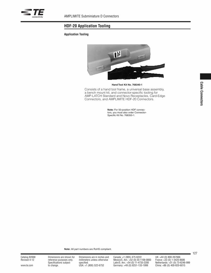
127Catalog 82068 Dimensions are shown for Dimensions are in inches and Canada: +1 (905) 475-6222 UK: +44 (0) 800-267666Revised 4-12 reference purposes only. millimeters unless otherwise Mexico/C. Am.: +52 (0) 55-1106-0800 France: +33 (0) 1-3420-8686
Specifications subject specified. Latin/S. Am.: +54 (0) 11-4733-2200 Netherlands: +31 (0) 73-6246-999www.te.com to change. USA: +1 (800) 522-6752 Germany: +49 (0) 6251-133-1999 China: +86 (0) 400-820-6015
AMPLIMITE Subminiature D Connectors
Note: All part numbers are RoHS compliant.
Cable Connectors
HDF-20 Application Tooling
Application Tooling
Hand Tool Kit No. 768340-1
Consists of a hand tool frame, a universal base assembly,a bench mount kit, and connector-specific tooling forAMP-LATCH Standard and Novo Receptacles, Card-EdgeConnectors, and AMPLIMITE HDF-20 Connectors.
Note: For 50-position HDF connec-tors, you must also order Connector-Specific Kit No. 768350-1.
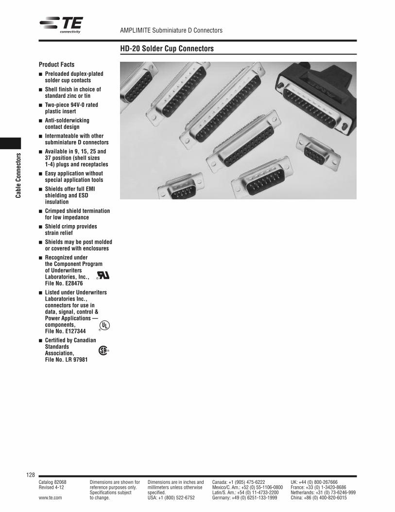
128Catalog 82068 Dimensions are shown for Dimensions are in inches and Canada: +1 (905) 475-6222 UK: +44 (0) 800-267666Revised 4-12 reference purposes only. millimeters unless otherwise Mexico/C. Am.: +52 (0) 55-1106-0800 France: +33 (0) 1-3420-8686
Specifications subject specified. Latin/S. Am.: +54 (0) 11-4733-2200 Netherlands: +31 (0) 73-6246-999www.te.com to change. USA: +1 (800) 522-6752 Germany: +49 (0) 6251-133-1999 China: +86 (0) 400-820-6015
AMPLIMITE Subminiature D Connectors
Cabl
e Co
nnec
tors
HD-20 Solder Cup Connectors
Product Facts Preloaded duplex-plated
solder cup contacts
Shell finish in choice ofstandard zinc or tin
Two-piece 94V-0 ratedplastic insert
Anti-solderwickingcontact design
Intermateable with othersubminiature D connectors
Available in 9, 15, 25 and37 position (shell sizes 1-4) plugs and receptacles
Easy application withoutspecial application tools
Shields offer full EMIshielding and ESDinsulation
Crimped shield terminationfor low impedance
Shield crimp provides strain relief
Shields may be post moldedor covered with enclosures
Recognized under the Component Program of Underwriters Laboratories, Inc.,File No. E28476
Listed under UnderwritersLaboratories Inc., connectors for use in data, signal, control &Power Applications — components, File No. E127344
Certified by CanadianStandards Association, File No. LR 97981
R
R
R
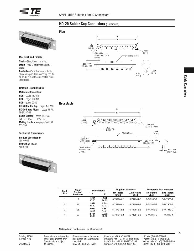
129Catalog 82068 Dimensions are shown for Dimensions are in inches and Canada: +1 (905) 475-6222 UK: +44 (0) 800-267666Revised 4-12 reference purposes only. millimeters unless otherwise Mexico/C. Am.: +52 (0) 55-1106-0800 France: +33 (0) 1-3420-8686
Specifications subject specified. Latin/S. Am.: +54 (0) 11-4733-2200 Netherlands: +31 (0) 73-6246-999www.te.com to change. USA: +1 (800) 522-6752 Germany: +49 (0) 6251-133-1999 China: +86 (0) 400-820-6015
AMPLIMITE Subminiature D Connectors
Note: All part numbers are RoHS compliant.
Cable Connectors
HD-20 Solder Cup Connectors (Continued)
Material and Finish:Shell—Steel, tin or zinc platedInsert—94V-0 rated thermoplastic,blackContacts—Phosphor bronze; duplexplated with gold flash on mating end, tinon solder cup, with entire contact nickelunderplated
Related Product Data:Mateable Connectors:HDE—pages 110-119HDF—pages 124-126HDP—pages 90-101HD-20 Solder Cup—pages 128-130HD-20 Board Mount—pages 54-71,78-85, 87-89Cable Clamps—pages 132, 133, 135-137, 140, 141, 144, 145Mating Hardware—pages 146-150,151-154
Technical Documents:
Product Specification108-40031Instruction Sheet408-9193
No. of Plug Part Numbers Receptacle Part NumbersShell Contact
DimensionsTin Plated Zinc Plated Tin Plated Zinc PlatedSize Positions A B Shell Shell Shell Shell
1.210 .9841 9 30.80 24.99 5-747904-2 5-747904-2 5-747905-2 5-747905-2
1.544 1.3132 15 39.20 33.32 5-747908-2 5-747908-2 5-747909-2 5-747909-2
2.089 1.8533 25 53.01 47.04 5-747912-2 5-747912-2 5-747913-2 5-747913-2
2.734 2.5024 37 69.40 63.50 5-747916-2 5-747916-2 5-747917-2 747917-4
Plug
Receptacle
.493[12.50]
.047[1.20]
Ø .122 [3.10]Clinch Nut
#4-40 UNC x 3.02 Plcs.
Grounding Indent
A
B
.607 ± .015
[15.40 ± 0.38]
.426[10.80]
.429 ± .015
[10.90 ± 0.38]
.109[2.77]
Typ.
Clinch Nut4-40 UNC-3B2 Plcs.
.122[3.10]
A
.587 ± .015
[14.90 ± 0.38]
B
.493[12.50]
.229[5.80]
Dia.2 Holes
.047[1.20]
Ref.Typ.
Mating Face
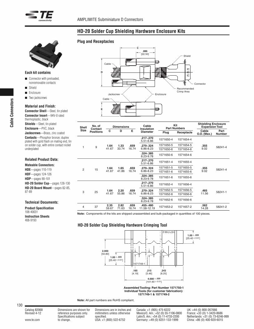
130Catalog 82068 Dimensions are shown for Dimensions are in inches and Canada: +1 (905) 475-6222 UK: +44 (0) 800-267666Revised 4-12 reference purposes only. millimeters unless otherwise Mexico/C. Am.: +52 (0) 55-1106-0800 France: +33 (0) 1-3420-8686
Specifications subject specified. Latin/S. Am.: +54 (0) 11-4733-2200 Netherlands: +31 (0) 73-6246-999www.te.com to change. USA: +1 (800) 522-6752 Germany: +49 (0) 6251-133-1999 China: +86 (0) 400-820-6015
AMPLIMITE Subminiature D Connectors
Note: All part numbers are RoHS compliant.
Cabl
e Co
nnec
tors
HD-20 Solder Cup Shielding Hardware Enclosure Kits
Each kit contains
Connector with preloaded,nonremovable contacts
Shield
Enclosure
Two jackscrews
Material and Finish:Connector Shell—Steel, tin platedConnector Insert—94V-0 rated thermoplastic, blackShields—Steel, tin platedEnclosure—PVC, blackJackscrews—Brass, zinc coatedContacts—Phosphor bronze; duplexplated with gold flash on mating end, tinon solder cup, with entire contact nickelunderplated
Related Product Data:Mateable Connectors:HDE—pages 110-119HDF—pages 124-126HDP—pages 90-101HD-20 Solder Cup—pages 128-130HD-20 Board Mount—pages 82-85,87-89
Technical Documents:
Product Specification108-40031Instruction Sheets408-9193
Plug and Receptacles
HD-20 Solder Cup Shielding Hardware Crimping Tool
Kit Shielding EnclosureShell No. of Dimensions Cable
Part Numbers Expansion ToolSize Contact
C D EInsulation
Cable PartPositions Diameter Plug Receptacle O.D. (Max.) Number.217-.270 1571650-4 1571654-45.51-6.86
1 9 1.64 1.33 .659 .270-.324 1571650-5 1571654-5 .355 58241-441.67 33.74 16.74 6.86-8.23 1571650-6 1571654-6 9.02
.324-.385 1571650-6 1571654-68.23-9.78
.217-.270 1571651-4 1571655-45.51-6.86
2 15 1.64 1.65 .659 .270-.324 1571651-5 1571655-5 .355 58241-441.67 41.86 16.74 6.86-8.23 1571651-6 1571655-6 9.02
.324-.385 1571651-6 1571655-68.23-9.78
.217-.270 1571652-4 1571656-45.51-6.86
3 25 1.64 2.20 .659 .270-.324 1571652-5 1571656-5 .465 58241-141.67 55.86 16.74 6.86-8.23 1571652-6 1571656-6 11.56
.324-.385 1571652-6 1571656-68.23-9.78
4 37 2.35 2.82 .659 .455-.480 1571653-2 1571657-2 .562 58241-259.67 71.63 16.74 11.58-12.19 14.28
Note: Components of the kits are shipped unassembled and bulk-packaged in quantities of 100 pieces.
Connector
Cable
Cable
EnclosureJackscrew
Shield
RecommendedCrimp Area
.886[22.50]
C
D
E
1571749-2
1571749-1
.165[4.19]
2.000[50.80]
.215[5.46]
.243[6.25]
4.000 ± .020
[101.60 ± 0.51]
1.00 ± .020
[25.40 ± 0.51]
1.00 ± .020
[25.40 ± 0.51]
Assembled Tooling: Part Number 1571750-1Individual Tools (for customer fabrication):
1571749-1 & 1571749-2
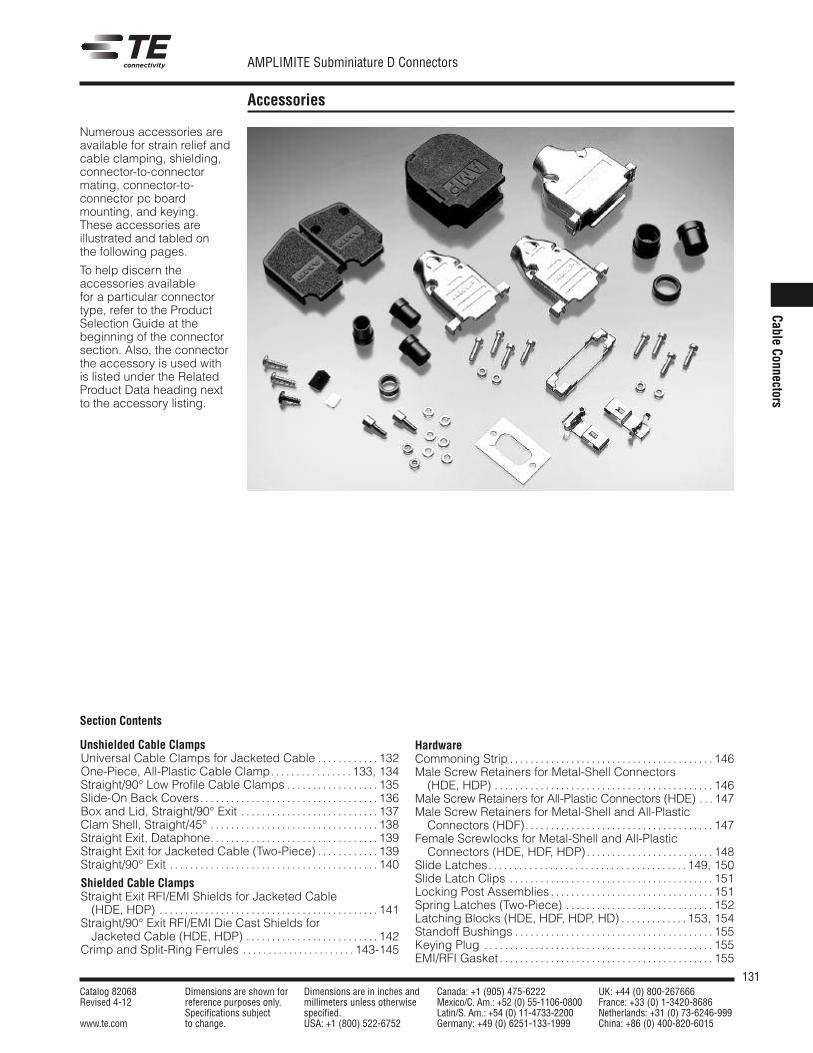
131Catalog 82068 Dimensions are shown for Dimensions are in inches and Canada: +1 (905) 475-6222 UK: +44 (0) 800-267666Revised 4-12 reference purposes only. millimeters unless otherwise Mexico/C. Am.: +52 (0) 55-1106-0800 France: +33 (0) 1-3420-8686
Specifications subject specified. Latin/S. Am.: +54 (0) 11-4733-2200 Netherlands: +31 (0) 73-6246-999www.te.com to change. USA: +1 (800) 522-6752 Germany: +49 (0) 6251-133-1999 China: +86 (0) 400-820-6015
AMPLIMITE Subminiature D Connectors
CableConnectors
Accessories
Numerous accessories areavailable for strain relief andcable clamping, shielding,connector-to-connectormating, connector-to-connector pc boardmounting, and keying.These accessories areillustrated and tabled onthe following pages.
To help discern theaccessories availablefor a particular connectortype, refer to the ProductSelection Guide at thebeginning of the connectorsection. Also, the connectorthe accessory is used withis listed under the RelatedProduct Data heading nextto the accessory listing.
Section Contents
Unshielded Cable ClampsUniversal Cable Clamps for Jacketed Cable . . . . . . . . . . . . 132One-Piece, All-Plastic Cable Clamp. . . . . . . . . . . . . . . . 133, 134Straight/90° Low Profile Cable Clamps . . . . . . . . . . . . . . . . . . 135Slide-On Back Covers. . . . . . . . . . . . . . . . . . . . . . . . . . . . . . . . . . . 136Box and Lid, Straight/90° Exit . . . . . . . . . . . . . . . . . . . . . . . . . . . 137Clam Shell, Straight/45° . . . . . . . . . . . . . . . . . . . . . . . . . . . . . . . . . 138Straight Exit, Dataphone. . . . . . . . . . . . . . . . . . . . . . . . . . . . . . . . . 139Straight Exit for Jacketed Cable (Two-Piece) . . . . . . . . . . . . 139Straight/90° Exit . . . . . . . . . . . . . . . . . . . . . . . . . . . . . . . . . . . . . . . . . 140
Shielded Cable ClampsStraight Exit RFI/EMI Shields for Jacketed Cable
(HDE, HDP) . . . . . . . . . . . . . . . . . . . . . . . . . . . . . . . . . . . . . . . . . . . 141Straight/90° Exit RFI/EMI Die Cast Shields for
Jacketed Cable (HDE, HDP) . . . . . . . . . . . . . . . . . . . . . . . . . . 142Crimp and Split-Ring Ferrules . . . . . . . . . . . . . . . . . . . . . . 143-145
HardwareCommoning Strip . . . . . . . . . . . . . . . . . . . . . . . . . . . . . . . . . . . . . . . . 146Male Screw Retainers for Metal-Shell Connectors
(HDE, HDP) . . . . . . . . . . . . . . . . . . . . . . . . . . . . . . . . . . . . . . . . . . . 146Male Screw Retainers for All-Plastic Connectors (HDE) . . . 147Male Screw Retainers for Metal-Shell and All-Plastic
Connectors (HDF). . . . . . . . . . . . . . . . . . . . . . . . . . . . . . . . . . . . . 147Female Screwlocks for Metal-Shell and All-Plastic
Connectors (HDE, HDF, HDP). . . . . . . . . . . . . . . . . . . . . . . . . 148Slide Latches. . . . . . . . . . . . . . . . . . . . . . . . . . . . . . . . . . . . . . . 149, 150Slide Latch Clips . . . . . . . . . . . . . . . . . . . . . . . . . . . . . . . . . . . . . . . . 151Locking Post Assemblies . . . . . . . . . . . . . . . . . . . . . . . . . . . . . . . . 151Spring Latches (Two-Piece) . . . . . . . . . . . . . . . . . . . . . . . . . . . . . 152Latching Blocks (HDE, HDF, HDP, HD) . . . . . . . . . . . . . 153, 154Standoff Bushings . . . . . . . . . . . . . . . . . . . . . . . . . . . . . . . . . . . . . . . 155Keying Plug . . . . . . . . . . . . . . . . . . . . . . . . . . . . . . . . . . . . . . . . . . . . . 155EMI/RFI Gasket . . . . . . . . . . . . . . . . . . . . . . . . . . . . . . . . . . . . . . . . . . 155
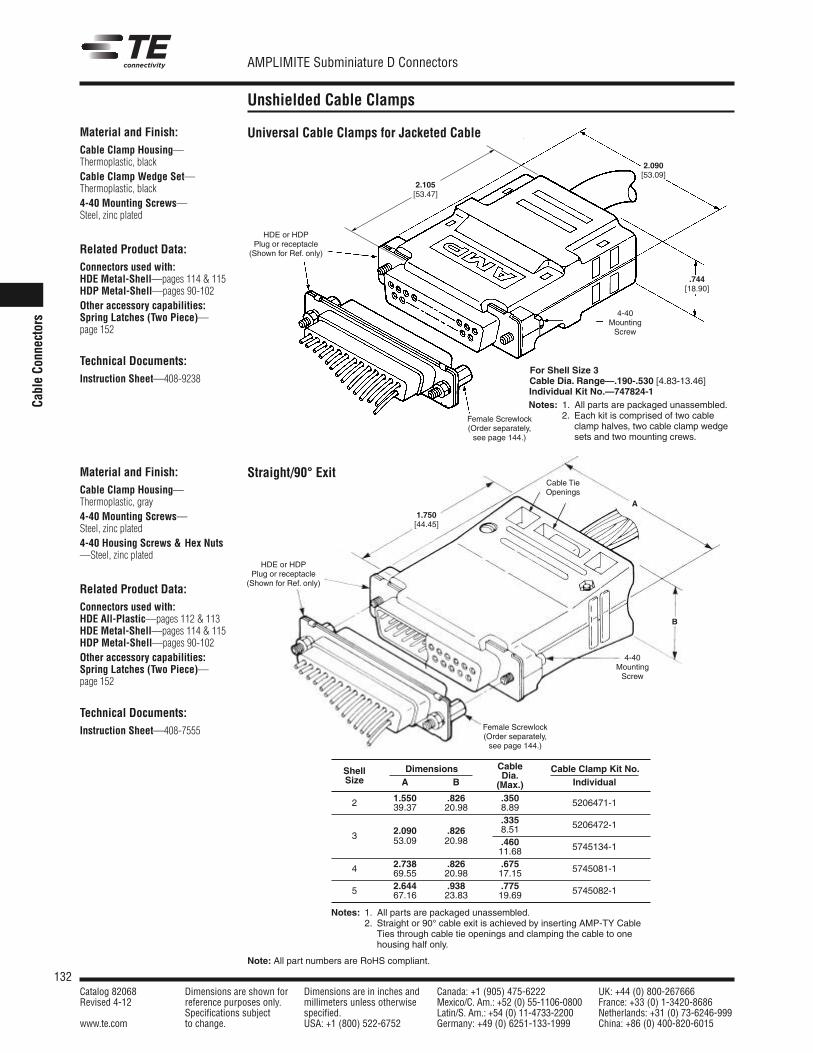
Note: All part numbers are RoHS compliant.
AMPLIMITE Subminiature D Connectors
Catalog 82068 Dimensions are shown for Dimensions are in inches and Canada: +1 (905) 475-6222 UK: +44 (0) 800-267666Revised 4-12 reference purposes only. millimeters unless otherwise Mexico/C. Am.: +52 (0) 55-1106-0800 France: +33 (0) 1-3420-8686
Specifications subject specified. Latin/S. Am.: +54 (0) 11-4733-2200 Netherlands: +31 (0) 73-6246-999www.te.com to change. USA: +1 (800) 522-6752 Germany: +49 (0) 6251-133-1999 China: +86 (0) 400-820-6015
132
CableCo
nnectors
Unshielded Cable Clamps
Material and Finish:Cable Clamp Housing—Thermoplastic, blackCable Clamp Wedge Set—Thermoplastic, black4-40 Mounting Screws—Steel, zinc plated
Related Product Data:Connectors used with:HDE Metal-Shell—pages 114 & 115HDP Metal-Shell—pages 90-102Other accessory capabilities:Spring Latches (Two Piece)—page 152
Technical Documents:Instruction Sheet—408-9238
2.105[53.47]
2.090[53.09]
.744[18.90]
HDE or HDPPlug or receptacle
(Shown for Ref. only)
Female Screwlock(Order separately,see page 144.)
4-40MountingScrew
Dimensions Cable Cable Clamp Kit No.Shell Dia.Size A B (Max.) Individual
2 1.550 .826 .350 5206471-139.37 20.98 8.89.335 5206472-1
2.090 .826 8.513 53.09 20.98 .460 5745134-111.68
4 2.738 .826 .675 5745081-169.55 20.98 17.15
5 2.644 .938 .775 5745082-167.16 23.83 19.69
Notes: 1. All parts are packaged unassembled.2. Straight or 90° cable exit is achieved by inserting AMP-TY Cable
Ties through cable tie openings and clamping the cable to onehousing half only.
For Shell Size 3Cable Dia. Range—.190-.530 [4.83-13.46]Individual Kit No.—747824-1Notes: 1. All parts are packaged unassembled.
2. Each kit is comprised of two cableclamp halves, two cable clamp wedgesets and two mounting crews.
Universal Cable Clamps for Jacketed Cable
A
B
HDE or HDPPlug or receptacle
(Shown for Ref. only)
Cable TieOpenings
Female Screwlock(Order separately,see page 144.)
4-40MountingScrew
1.750[44.45]
Material and Finish:Cable Clamp Housing—Thermoplastic, gray4-40 Mounting Screws—Steel, zinc plated4-40 Housing Screws & Hex Nuts—Steel, zinc plated
Related Product Data:Connectors used with:HDE All-Plastic—pages 112 & 113HDE Metal-Shell—pages 114 & 115HDP Metal-Shell—pages 90-102Other accessory capabilities:Spring Latches (Two Piece)—page 152
Technical Documents:Instruction Sheet—408-7555
Straight/90° Exit
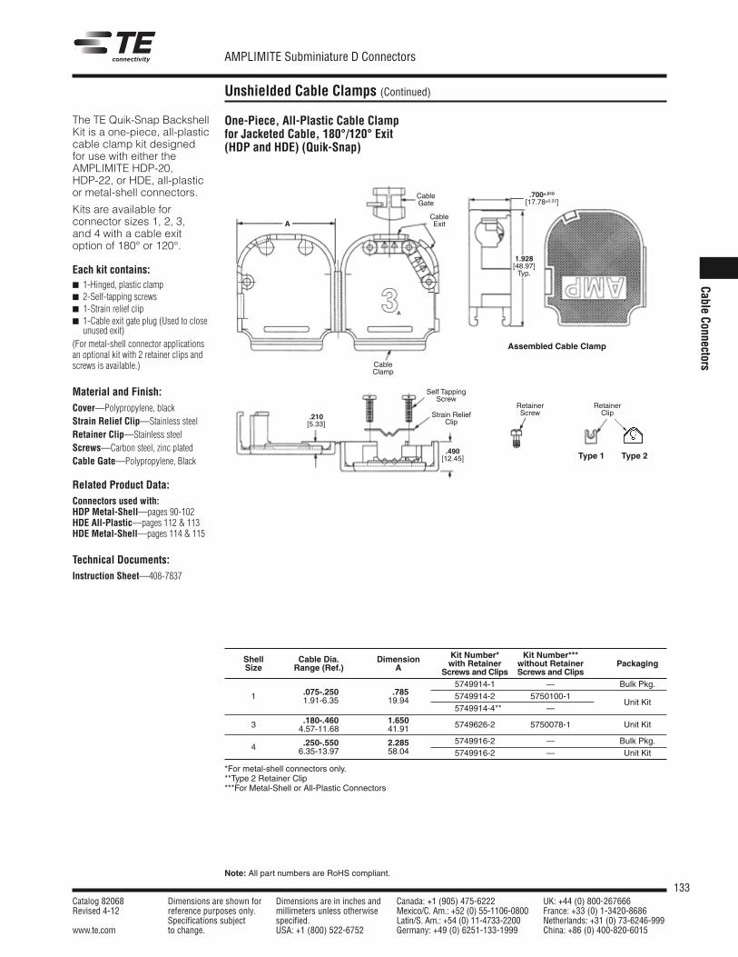
133Catalog 82068 Dimensions are shown for Dimensions are in inches and Canada: +1 (905) 475-6222 UK: +44 (0) 800-267666Revised 4-12 reference purposes only. millimeters unless otherwise Mexico/C. Am.: +52 (0) 55-1106-0800 France: +33 (0) 1-3420-8686
Specifications subject specified. Latin/S. Am.: +54 (0) 11-4733-2200 Netherlands: +31 (0) 73-6246-999www.te.com to change. USA: +1 (800) 522-6752 Germany: +49 (0) 6251-133-1999 China: +86 (0) 400-820-6015
AMPLIMITE Subminiature D Connectors
Note: All part numbers are RoHS compliant.
CableConnectors
Unshielded Cable Clamps (Continued)
One-Piece, All-Plastic Cable Clampfor Jacketed Cable, 180°/120° Exit(HDP and HDE) (Quik-Snap)
Kit Number* Kit Number***Shell Cable Dia. Dimension with Retainer without RetainerSize Range (Ref.) A Screws and Clips Screws and ClipsPackaging
.075-.250 .7855749914-1 — Bulk Pkg.
1 1.91-6.35 19.94 5749914-2 5750100-1Unit Kit
5749914-4** —.180-.460 1.6503 4.57-11.68 41.91 5749626-2 5750078-1 Unit Kit
.250-.550 2.285 5749916-2 — Bulk Pkg.4 6.35-13.97 58.04 5749916-2 — Unit Kit
*For metal-shell connectors only.**Type 2 Retainer Clip***For Metal-Shell or All-Plastic Connectors
A
CableGate
Self TappingScrew
RetainerScrew
RetainerClipStrain Relief
Clip
CableExit
CableClamp
.700±.010[17.78±0.25]
1.928[48.97]Typ.
.490[12.45]
.210[5.33]
Assembled Cable Clamp
The TE Quik-Snap BackshellKit is a one-piece, all-plasticcable clamp kit designedfor use with either theAMPLIMITE HDP-20,HDP-22, or HDE, all-plasticor metal-shell connectors.
Kits are available forconnector sizes 1, 2, 3,and 4 with a cable exitoption of 180° or 120°.
Each kit contains: 1-Hinged, plastic clamp 2-Self-tapping screws 1-Strain relief clip 1-Cable exit gate plug (Used to close
unused exit)(For metal-shell connector applicationsan optional kit with 2 retainer clips andscrews is available.)
Material and Finish:Cover—Polypropylene, blackStrain Relief Clip—Stainless steelRetainer Clip—Stainless steelScrews—Carbon steel, zinc platedCable Gate—Polypropylene, Black
Related Product Data:Connectors used with:HDP Metal-Shell—pages 90-102HDE All-Plastic—pages 112 & 113HDE Metal-Shell—pages 114 & 115
Technical Documents:Instruction Sheet—408-7837
Type 1 Type 2
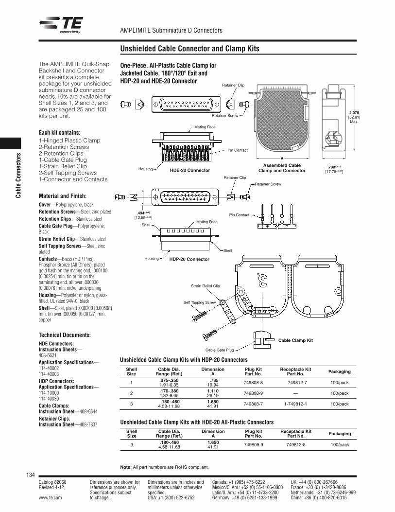
134Catalog 82068 Dimensions are shown for Dimensions are in inches and Canada: +1 (905) 475-6222 UK: +44 (0) 800-267666Revised 4-12 reference purposes only. millimeters unless otherwise Mexico/C. Am.: +52 (0) 55-1106-0800 France: +33 (0) 1-3420-8686
Specifications subject specified. Latin/S. Am.: +54 (0) 11-4733-2200 Netherlands: +31 (0) 73-6246-999www.te.com to change. USA: +1 (800) 522-6752 Germany: +49 (0) 6251-133-1999 China: +86 (0) 400-820-6015
AMPLIMITE Subminiature D Connectors
Note: All part numbers are RoHS compliant.
CableCo
nnectors
Unshielded Cable Connector and Clamp Kits
One-Piece, All-Plastic Cable Clamp forJacketed Cable, 180°/120° Exit andHDP-20 and HDE-20 Connector
The AMPLIMITE Quik-SnapBackshell and Connectorkit presents a completepackage for your unshieldedsubminiature D connectorneeds. Kits are available forShell Sizes 1, 2 and 3, andare packaged 25 and 100kits per unit.
Each kit contains:1-Hinged Plastic Clamp2-Retention Screws2-Retention Clips1-Cable Gate Plug1-Strain Relief Clip2-Self Tapping Screws1-Connector and Contacts
Material and Finish:Cover—Polypropylene, blackRetention Screws—Steel, zinc platedRetention Clips—Stainless steelCable Gate Plug—Polypropylene,BlackStrain Relief Clip—Stainless steelSelf Tapping Screws—Steel, zincplatedContacts—Brass (HDP Pins),Phosphor Bronze (All Others), platedgold flash on the mating end, .000100[0.00254] min. tin or tin on theterminating end, all over .000030[0.00076] min. nickel underplatingHousing—Polyester or nylon, glass-filled, UL rated 94V-0, blackShell—Steel, plated .000200 [0.00508]min. tin over .000050 [0.00127] min.copper
Technical Documents:HDE Connectors:Instruction Sheets—408-6621Application Specifications—114-40002114-40003HDP Connectors:Application Specifications—114-10000114-40030Cable Clamps:Instruction Sheet—408-9544Retainer Clips:Instruction Sheet—408-7837
Shell Cable Dia. Dimension Plug Kit Receptacle KitSize Range (Ref.) A Part No. Part No. Packaging
.075-.250 .785 749808-8 100/pack1 1.91-6.35 19.94 749812-7
.170-.380 1.110 749808-9 100/pack2 4.32-9.65 28.19 —
.180-.460 1.650 749808-7 1-749812-1 100/pack3 4.58-11.68 41.91
Unshielded Cable Clamp Kits with HDP-20 Connectors
Shell Cable Dia. Dimension Plug Kit Receptacle KitSize Range (Ref.) A Part No. Part No. Packaging
.180-.460 1.6503 4.58-11.68 41.91 749809-9 749813-8 100/pack
Unshielded Cable Clamp Kits with HDE-20 All-Plastic Connectors
.494±.015[12.55±0.38]
A
2.079[52.81]Max.
.700±.015[17.78±0.38]
Retainer Clip
Strain Relief Clip
Self Tapping Screw
Cable Gate Plug
Retainer Clip
Retainer Screw
Retainer Screw
Pin Contact
Pin Contact
ShellMating Face
Mating Face
Housing
Housing
Shell
HDE-20 Connector
HDP-20 Connector
Assembled CableClamp and Connector
Cable Clamp Kit
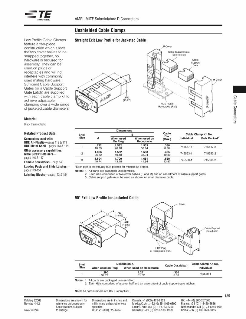
135Catalog 82068 Dimensions are shown for Dimensions are in inches and Canada: +1 (905) 475-6222 UK: +44 (0) 800-267666Revised 4-12 reference purposes only. millimeters unless otherwise Mexico/C. Am.: +52 (0) 55-1106-0800 France: +33 (0) 1-3420-8686
Specifications subject specified. Latin/S. Am.: +54 (0) 11-4733-2200 Netherlands: +31 (0) 73-6246-999www.te.com to change. USA: +1 (800) 522-6752 Germany: +49 (0) 6251-133-1999 China: +86 (0) 400-820-6015
AMPLIMITE Subminiature D Connectors
Note: All part numbers are RoHS compliant.
CableConnectors
Unshielded Cable Clamps
Low Profile Cable Clampsfeature a two-piececonstruction which allowsthe two cover halves to besnapped together, nohardware is required forassembly. They can beused on plugs orreceptacles and will notinterfere with commonlyused mating hardware.Sufficient Cable SupportGates (or a Cable SupportGate Latch) are suppliedwith each cable clamp kit toachieve adjustableclamping over a wide rangeof jacketed cable diameters.
MaterialBlack thermoplastic
Related Product Data:Connectors used with:HDE All-Plastic—pages 112 & 113HDE Metal-Shell—pages 114 & 115Other accessory capabilities:Male Screw Retainers—pages 146 & 147Female Screwlocks—page 148Locking Posts and Slide Latches—pages 149-151Latching Blocks—pages 153 & 154
Straight Exit Low Profile for Jacketed Cable
90° Exit Low Profile for Jacketed Cable
BA
A
F Cover
.550[13.97]
.732[18.59]
.550[13.97]
Cable Support Gate(See Note 3.)
CableSupportGate
M Cover
HDE Plug orReceptacle (Ref.)
Cover
Cable SupportGate Latch
HDE Plugor Receptacle (Ref.)
DimensionsB CableShell
When used When used onDia.
Cable Clamp Kit No.Size A
On Plug Receptacle(Max.) Individual Bulk Packed*
1 .732 1.582 1.533 .330 745547-1 745547-218.59 40.18 38.94 8.38
2 1.056 1.582 1.533 .425 745553-1 745553-226.82 40.18 38.94 10.80
3 1.604 1.700 1.651 .550 745560-1 745560-240.74 43.18 41.94 13.97
*Each part is individually bulk packed for multiple kit orders.Notes: 1. All parts are packaged unassembled.
2. Each kit is comprised of two cover halves (F and M) and an assortment of cable support gates.3. Cable support gate must be used as shown for small diameter cable.
Shell Dimension ACable Dia. (Max.)
Cable Clamp Kit No.Size When used on Plug When used on Receptacle Individual
1 1.290 1.241 .330 745550-132.77 31.52 8.38
Notes: 1. All parts are packaged unassembled.2. Each kit is comprised of a cover half and an assortment of cable support gate latches.
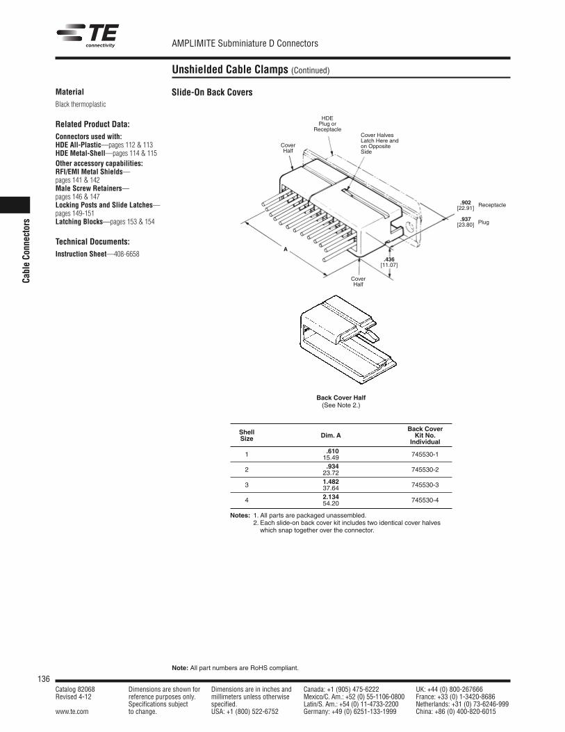
136Catalog 82068 Dimensions are shown for Dimensions are in inches and Canada: +1 (905) 475-6222 UK: +44 (0) 800-267666Revised 4-12 reference purposes only. millimeters unless otherwise Mexico/C. Am.: +52 (0) 55-1106-0800 France: +33 (0) 1-3420-8686
Specifications subject specified. Latin/S. Am.: +54 (0) 11-4733-2200 Netherlands: +31 (0) 73-6246-999www.te.com to change. USA: +1 (800) 522-6752 Germany: +49 (0) 6251-133-1999 China: +86 (0) 400-820-6015
AMPLIMITE Subminiature D Connectors
Note: All part numbers are RoHS compliant.
CableCo
nnectors
Unshielded Cable Clamps (Continued)
MaterialBlack thermoplastic
Related Product Data:Connectors used with:HDE All-Plastic—pages 112 & 113HDE Metal-Shell—pages 114 & 115Other accessory capabilities:RFI/EMI Metal Shields—pages 141 & 142Male Screw Retainers—pages 146 & 147Locking Posts and Slide Latches—pages 149-151Latching Blocks—pages 153 & 154
Technical Documents:Instruction Sheet—408-6658
Slide-On Back Covers
Back Cover Half(See Note 2.)
Back CoverShell Dim. A Kit No.Size Individual.6101 15.49 745530-1
.9342 23.72 745530-2
1.4823 37.64 745530-3
2.1344 54.20 745530-4
Notes: 1. All parts are packaged unassembled.2. Each slide-on back cover kit includes two identical cover halves
which snap together over the connector.
HDEPlug or
ReceptacleCover HalvesLatch Here andon OppositeSide
CoverHalf
CoverHalf
.436[11.07]
.902[22.91]
.937[23.80]
A
Receptacle
Plug
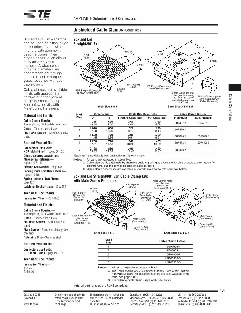
137Catalog 82068 Dimensions are shown for Dimensions are in inches and Canada: +1 (905) 475-6222 UK: +44 (0) 800-267666Revised 4-12 reference purposes only. millimeters unless otherwise Mexico/C. Am.: +52 (0) 55-1106-0800 France: +33 (0) 1-3420-8686
Specifications subject specified. Latin/S. Am.: +54 (0) 11-4733-2200 Netherlands: +31 (0) 73-6246-999www.te.com to change. USA: +1 (800) 522-6752 Germany: +49 (0) 6251-133-1999 China: +86 (0) 400-820-6015
AMPLIMITE Subminiature D Connectors
Note: All part numbers are RoHS compliant.
CableConnectors
Unshielded Cable Clamps (Continued)
Shell Dimensions Cable Dia. Max. (Ref.) Cable Clamp Kit No.Size A B Straight Cable Exit 90° Cable Exit Individual Bulk Packed*
.755 .630 .160 .1601 19.18 16.00 4.06 4.06 207467-1 207467-2
1.078 .630 .320 .3202 27.38 16.00 8.13 8.13 207470-1 —
1.620 .770 .390 .3903 41.15 19.56 9.91 9.91 207345-1 207345-2
2.268 .770 .640 .4054 57.61 19.56 16.26 10.29 207473-1 207473-2
2.178 .880 .490 .4905 55.32 22.35 12.45 12.45 207476-1 —
*Each part is individually bulk packed for multiple kit orders.Notes: 1. All parts are packaged unassembled.
2. Cable diameter is adjustable by changing cable support gates. Use the flat side of cable support gates fordiscrete wire, and the semicircle side for jacketed cable.
Notes: 3. Cable clamp assemblies are available in kits with male screw retainers, see below.
Shell Cable Clamp Kit No.Size1 5207908-12 5207908-43 5207908-74 1-5207908-05 1-5207908-3
Notes: 1. All parts are packaged unassembled.2. Each kit is comprised of a cable clamp and male screw retainer
hardware(2 each). Male screw retainers are also available in kitform, see page 146.
3. For ordering cable clamps separately, see above.
Box and Lid Straight/90° Exit Cable Clamp Kitswith Male Screw Retainers
HDP Plug or Receptacle(Shown for Ref. only)
Self-TappingScrew
TexturedFinish
Typical Cable SupportGate (Supplied withCable Clamp Kit)
Cable Gates are inter-changeable allowing90° and 180° cable
exit. Blank gate shownin 90° exit.
1.70[43.18]
A Max.
B Max.
Retaining Clip(See Note 2.)Retaining Clip
(See Note 2.)
Male Screws matewith FemaleScrewlocks
(See page 144.)
Male Screws matewith FemaleScrewlocks
(See page 144.)
Male Screw(See Note 2.)Male Screw
(See Note 2.)
B Max.
A Max.
1.70[43.18]
Cable Clamp(See Note 3.)
HDP Plug orReceptacle(Shown forRef. only)
TexturedFinish
HDP Plug orReceptacle(Shown forRef. only)
Self-TappingScrew
Shell Size 1 & 2 Shell Size 3 & 4 & 5
Shell Size 1 & 2 Shell Size 3 & 4 & 5
Box and LidStraight/90° Exit
Box and Lid Cable Clampscan be used on either plugsor receptacles and will notinterfere with commonlyused hardware. Theirhinged construction allowseasy assembly to aharness. A wide rangeof cable diameters areaccommodated throughthe use of cable supportgates, supplied with eachcable clamp.
Cable clamps are availablein kits with appropriatehardware for convenientplug/receptacle mating.See below for kits withMale Screw Retainers.
Material and Finish:Cable Clamp Housing—Thermoplastic, black with textured finishGates—Thermoplastic, blackFlat Head Screws—Steel, black, zincplated
Related Product Data:Connectors used with:HDP Metal-Shell—pages 90-102Other accessory capabilities:Male Screw Retainers—pages 146 & 147Female Screwlocks—page 148Locking Posts and Slide Latches—pages 149-151Spring Latches (Two Piece)—page 152Latching Blocks—pages 153 & 154
Technical Documents:Instruction Sheet—408-7555
Material and Finish:
Cable Clamp Housing—Thermoplastic, black with textured finishGates—Thermoplastic, blackFlat Head Screws—Steel, black, zincplatedMale Screw—Steel, zinc plated yellowchromateRetaining Clip—Stainless steel
Related Product Data:
Connectors used with:HDP Metal-Shell—pages 90-102
Technical Documents::Instruction Sheets—408-7555408-7837
HDP Plug or Receptacle(Shown for Ref. only)
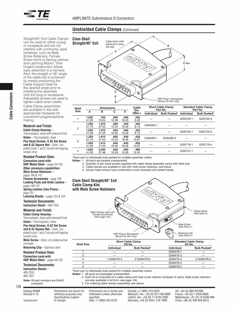
138Catalog 82068 Dimensions are shown for Dimensions are in inches and Canada: +1 (905) 475-6222 UK: +44 (0) 800-267666Revised 4-12 reference purposes only. millimeters unless otherwise Mexico/C. Am.: +52 (0) 55-1106-0800 France: +33 (0) 1-3420-8686
Specifications subject specified. Latin/S. Am.: +54 (0) 11-4733-2200 Netherlands: +31 (0) 73-6246-999www.te.com to change. USA: +1 (800) 522-6752 Germany: +49 (0) 6251-133-1999 China: +86 (0) 400-820-6015
AMPLIMITE Subminiature D Connectors
CableCo
nnectors
Unshielded Cable Clamps (Continued)
Clam ShellStraight/45° Exit
Straight/45° Exit Cable Clampscan be used on either a plugor receptacle and will notinterfere with commonly usedhardware, such as MaleScrew Retainers, FemaleScrew-locks or Spring Latchesand Latching Blocks. Theirhinged construction allowseasy assembly to a harness.Also, the straight or 45° angleof the cable exit is achievedby merely positioning theCable Support Gate forthe desired angle prior toinstalling the assemblyonto the plug or receptacle.Adjustable screws are used totighten cable strain reliefs.Cable Clamp assembliesare available in kits withappropriate hardware forconvenient plug/receptaclemating.
Material and Finish:Cable Clamp Housing—Thermoplastic, black with textured finishGates—Thermoplastic, blackPan Head Screws, 6-32 Set Screwand 6-32 Square Nut—Steel, zincplated (sizes 1 and 2 include self-tappingscrews only)
Related Product Data:Connectors used with:HDP Metal-Shell—pages 90-102Other accessory capabilities:Male Screw Retainers—pages 146 & 147Female Screwlocks—page 148Locking Posts and Slide Latches—pages 149-151Spring Latches (Two Piece)—page 152Latching Blocks—pages 153 & 154
Technical Documents:Instruction Sheet—408-7555
Material and Finish:Cable Clamp Housing—Thermoplastic, black with textured finishGates—Thermoplastic, blackPan Head Screws, 6-32 Set Screwand 6-32 Square Nut—Steel, zincplated (sizes 1 and 2 include self-tappingscrews only)Male Screw—Steel, zinc plated yellowchromateRetaining Clip—Stainless steel
Related Product Data:Connectors used with:HDP Metal-Shell—pages 90-102
Technical Documents:Instruction Sheets—408-7555408-7837Note: All part numbers are RoHS
compliant.
Cable strain reliefadjustment screwthis side
Cable Short Cable Clamp Standard Cable ClampShell DimensionsDia. Part No. Part No.Size A B C D (Max.) Individual Bulk Packed* Individual Bulk Packed*
1.625 .750 .640 .640 .2561 41.28 19.05 16.26 16.26 6.30 — — 5205729-1 5205729-3
1.250 1.073 .600 .640 .32031.75 27.25 15.24 16.26 8.13 5206393-1 — — —
1.625 1.073 .640 .640 .3202
41.28 27.25 16.26 16.26 8.13 — — 5205730-1 5205730-3
1.250 1.615 .600 .640 .42031.75 41.02 15.24 16.26 10.67 5206390-1 5206390-3 — —
1.625 1.615 .640 .640 .4203
41.28 41.02 16.26 16.26 10.67 — — 5205718-1 5205718-4
1.625 2.263 .640 .640 .4904 41.28 57.48 16.26 16.26 12.45 — — 5205731-1 —
*Each part is individually bulk packed for multiple assembly orders.Notes: 1. All parts are packed unassembled.
2. Quantity of pan head screws supplied with cable clamp assembly varies with shell size.3. Cable clamps are available in kits with male screw retainers, see below.4. All pan head screws have combination cross-recessed and slotted heads.
Clam Shell Straight/45° ExitCable Clamp Kitswith Male Screw Retainers
HDP Plug or Receptacle(Shown for Ref. only)
B
C Max.
D
HDP Plug or Receptacle(Shown for Ref. only)
Male Screws mate withFemale Screwlocks(See page 144.)
Cable Clamp(See Note 3.)
Male Screw(See Note 2.)
Retaining Clip(See Note 2.)
Short Cable Clamp Standard Cable ClampShell Size KIt No. Kit No.
Individual Bulk Packed* Individual Bulk Packed*1 — — 5206478-1 —2 — — 5206478-2 —3 1-5206478-2 2-5206478-6 5206478-3 2-5206478-24 — — 5206478-4 —5 — — 5206478-5 —
*Each part is individually bulk packed for multiple assembly orders.Notes: 1. All parts are packaged unassembled.
2. Each kit is comprised of a cable clamp and male screw retainer hardware (2 each). Male screw retainersare also available in kit form, see page 146.
3. For ordering cable clamps separately, see above.
A
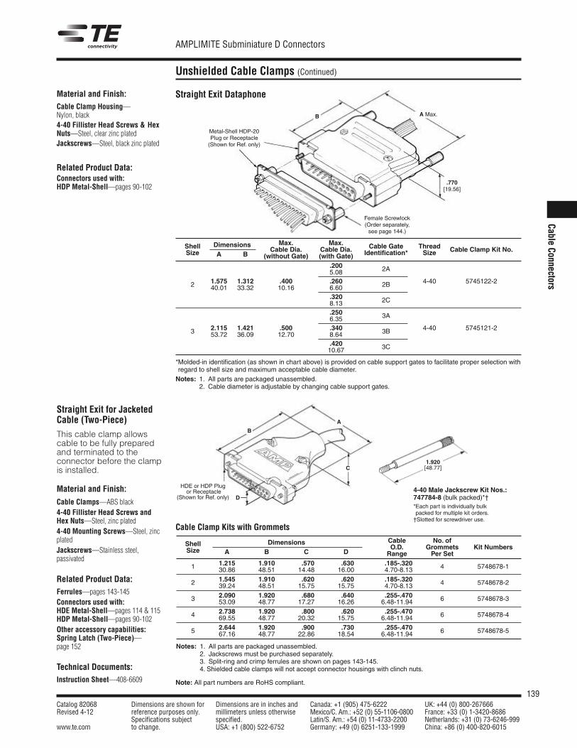
139Catalog 82068 Dimensions are shown for Dimensions are in inches and Canada: +1 (905) 475-6222 UK: +44 (0) 800-267666Revised 4-12 reference purposes only. millimeters unless otherwise Mexico/C. Am.: +52 (0) 55-1106-0800 France: +33 (0) 1-3420-8686
Specifications subject specified. Latin/S. Am.: +54 (0) 11-4733-2200 Netherlands: +31 (0) 73-6246-999www.te.com to change. USA: +1 (800) 522-6752 Germany: +49 (0) 6251-133-1999 China: +86 (0) 400-820-6015
AMPLIMITE Subminiature D Connectors
CableConnectors
Unshielded Cable Clamps (Continued)
Metal-Shell HDP-20Plug or Receptacle(Shown for Ref. only)
Female Screwlock(Order separately,see page 144.)
A Max.B
.770[19.56]
Max. Max.Shell DimensionsCable Dia. Cable Dia. Cable Gate Thread Cable Clamp Kit No.Size A B (without Gate) (with Gate) Identification* Size
.200 2A5.08
2 1.575 1.312 .400 .260 2B 4-40 5745122-240.01 33.32 10.16 6.60
.320 2C8.13
.250 3A6.35
3 2.115 1.421 .500 .340 3B 4-40 5745121-253.72 36.09 12.70 8.64
.420 3C10.67
*Molded-in identification (as shown in chart above) is provided on cable support gates to facilitate proper selection withregard to shell size and maximum acceptable cable diameter.Notes: 1. All parts are packaged unassembled.
2. Cable diameter is adjustable by changing cable support gates.
Straight Exit DataphoneMaterial and Finish:Cable Clamp Housing—Nylon, black4-40 Fillister Head Screws & HexNuts—Steel, clear zinc platedJackscrews—Steel, black zinc plated
Related Product Data:Connectors used with:HDP Metal-Shell—pages 90-102
Straight Exit for JacketedCable (Two-Piece)
HDE or HDP Plugor Receptacle
(Shown for Ref. only)
A
B
C
D
1.920[48.77]
4-40 Male Jackscrew Kit Nos.:747784-8 (bulk packed)*†*Each part is individually bulkpacked for multiple kit orders.†Slotted for screwdriver use.
Cable Clamp Kits with GrommetsCable No. ofShell DimensionsO.D. Grommets Kit NumbersSize A B C D Range Per Set
1.215 1.910 .570 .630 .185-.3201 30.86 48.51 14.48 16.00 4.70-8.13 4 5748678-1
1.545 1.910 .620 .620 .185-.3202 39.24 48.51 15.75 15.75 4.70-8.13 4 5748678-2
2.090 1.920 .680 .640 .255-.4703 53.09 48.77 17.27 16.26 6.48-11.94 6 5748678-3
2.738 1.920 .800 .620 .255-.4704 69.55 48.77 20.32 15.75 6.48-11.94 6 5748678-4
2.644 1.920 .900 .730 .255-.4705 67.16 48.77 22.86 18.54 6.48-11.94 6 5748678-5
Notes: 1. All parts are packaged unassembled.2. Jackscrews must be purchased separately.3. Split-ring and crimp ferrules are shown on pages 143-145.4. Shielded cable clamps will not accept connector housings with clinch nuts.
This cable clamp allowscable to be fully preparedand terminated to theconnector before the clampis installed.
Material and Finish:
Cable Clamps—ABS black4-40 Fillister Head Screws andHex Nuts—Steel, zinc plated4-40 Mounting Screws—Steel, zincplatedJackscrews—Stainless steel,passivated
Related Product Data:Ferrules—pages 143-145Connectors used with:HDE Metal-Shell—pages 114 & 115HDP Metal-Shell—pages 90-102Other accessory capabilities:Spring Latch (Two-Piece)—page 152
Technical Documents:Instruction Sheet—408-6609 Note: All part numbers are RoHS compliant.
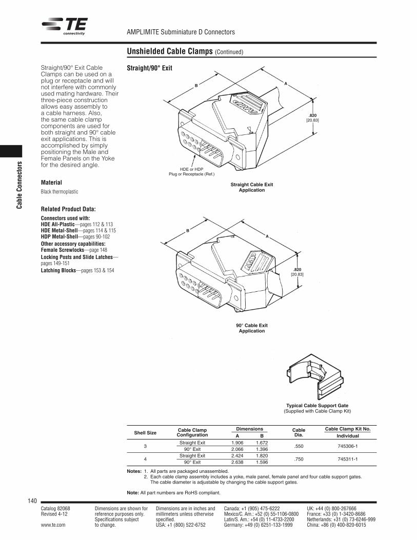
140Catalog 82068 Dimensions are shown for Dimensions are in inches and Canada: +1 (905) 475-6222 UK: +44 (0) 800-267666Revised 4-12 reference purposes only. millimeters unless otherwise Mexico/C. Am.: +52 (0) 55-1106-0800 France: +33 (0) 1-3420-8686
Specifications subject specified. Latin/S. Am.: +54 (0) 11-4733-2200 Netherlands: +31 (0) 73-6246-999www.te.com to change. USA: +1 (800) 522-6752 Germany: +49 (0) 6251-133-1999 China: +86 (0) 400-820-6015
AMPLIMITE Subminiature D Connectors
Note: All part numbers are RoHS compliant.
CableCo
nnectors
Unshielded Cable Clamps (Continued)
Straight/90° Exit CableClamps can be used on aplug or receptacle and willnot interfere with commonlyused mating hardware. Theirthree-piece constructionallows easy assembly toa cable harness. Also,the same cable clampcomponents are used forboth straight and 90° cableexit applications. This isaccomplished by simplypositioning the Male andFemale Panels on the Yokefor the desired angle.
MaterialBlack thermoplastic
Related Product Data:Connectors used with:HDE All-Plastic—pages 112 & 113HDE Metal-Shell—pages 114 & 115HDP Metal-Shell—pages 90-102Other accessory capabilities:Female Screwlocks—page 148Locking Posts and Slide Latches—pages 149-151Latching Blocks—pages 153 & 154
.820[20.83]
B A
BA
.820[20.83]
HDE or HDPPlug or Receptacle (Ref.)
Straight Cable ExitApplication
90° Cable ExitApplication
Typical Cable Support Gate(Supplied with Cable Clamp Kit)
Shell Size Cable Clamp Dimensions Cable Cable Clamp Kit No.Configuration A B Dia. IndividualStraight Exit 1.906 1.672
390° Exit 2.066 1.396
.550 745306-1
Straight Exit 2.424 1.8204
90° Exit 2.638 1.596.750 745311-1
Notes: 1. All parts are packaged unassembled.2. Each cable clamp assembly includes a yoke, male panel, female panel and four cable support gates.
The cable diameter is adjustable by changing the cable support gates.
Straight/90° Exit
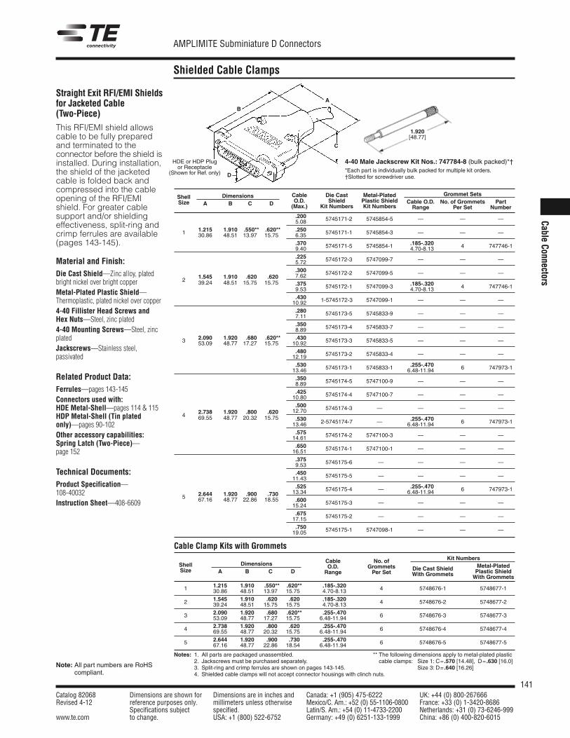
141Catalog 82068 Dimensions are shown for Dimensions are in inches and Canada: +1 (905) 475-6222 UK: +44 (0) 800-267666Revised 4-12 reference purposes only. millimeters unless otherwise Mexico/C. Am.: +52 (0) 55-1106-0800 France: +33 (0) 1-3420-8686
Specifications subject specified. Latin/S. Am.: +54 (0) 11-4733-2200 Netherlands: +31 (0) 73-6246-999www.te.com to change. USA: +1 (800) 522-6752 Germany: +49 (0) 6251-133-1999 China: +86 (0) 400-820-6015
AMPLIMITE Subminiature D Connectors
CableConnectors
Shielded Cable Clamps
Note: All part numbers are RoHScompliant.
Cable Die Cast Metal-Plated Grommet SetsShell DimensionsO.D. Shield Plastic Shield Cable O.D. No. of Grommets PartSize A B C D (Max.) Kit Numbers Kit Numbers Range Per Set Number
.2005.08 5745171-2 5745854-5 — — —
1.215 1.910 .550** .620** .2501 30.86 48.51 13.97 15.75 6.35 5745171-1 5745854-3 — — —
.370 .185-.3209.40 5745171-5 5745854-1 4.70-8.13 4 747746-1
.2255.72 5745172-3 5747099-7 — — —
.3001.545 1.910 .620 .620 7.62 5745172-2 5747099-5 — — —
2 39.24 48.51 15.75 15.75 .375 .185-.3209.53 5745172-1 5747099-3 4.70-8.13 4 747746-1
.43010.92 1-5745172-3 5747099-1 — — —
.2807.11 5745173-5 5745833-9 — — —
.3508.89 5745173-4 5745833-7 — — —
2.090 1.920 .680 .620** .4303 53.09 48.77 17.27 15.75 10.92 5745173-3 5745833-5 — — —
.48012.19 5745173-2 5745833-4 — — —
.530 .255-.47013.46 5745173-1 5745833-1 6.48-11.94 6 747973-1
.3508.89 5745174-5 5747100-9 — — —
.42510.80 5745174-4 5747100-7 — — —
.5002.738 1.920 .800 .620 12.70 5745174-3 — — — —
4 69.55 48.77 20.32 15.75 .530 .255-.47013.46 2-5745174-7 — 6.48-11.94 6 747973-1
.57514.61 5745174-2 5747100-3 — — —
.65016.51 5745174-1 5747100-1 — — —
.3759.53 5745175-6 — — — —
.45011.43 5745175-5 — — — —
2.644 1.920 .900 .730.525 .255-.470
5 67.16 48.77 22.86 18.5513.34 5745175-4 — 6.48-11.94 6 747973-1
.60015.24 5745175-3 — — — —
.67517.15 5745175-2 — — — —
.75019.05 5745175-1 5747098-1 — — —
Straight Exit RFI/EMI Shieldsfor Jacketed Cable(Two-Piece)This RFI/EMI shield allowscable to be fully preparedand terminated to theconnector before the shield isinstalled. During installation,the shield of the jacketedcable is folded back andcompressed into the cableopening of the RFI/EMIshield. For greater cablesupport and/or shieldingeffectiveness, split-ring andcrimp ferrules are available(pages 143-145).
Material and Finish:Die Cast Shield—Zinc alloy, platedbright nickel over bright copperMetal-Plated Plastic Shield—Thermoplastic, plated nickel over copper4-40 Fillister Head Screws andHex Nuts—Steel, zinc plated4-40 Mounting Screws—Steel, zincplatedJackscrews—Stainless steel,passivated
Related Product Data:Ferrules—pages 143-145Connectors used with:HDE Metal-Shell—pages 114 & 115HDP Metal-Shell (Tin platedonly)—pages 90-102Other accessory capabilities:Spring Latch (Two-Piece)—page 152
Technical Documents:Product Specification—108-40032Instruction Sheet—408-6609
Cable Clamp Kits with GrommetsKit NumbersCable No. of
Metal-PlatedShell Dimensions O.D. Grommets Die Cast Shield Plastic ShieldSize A B C D Range Per Set With Grommets With Grommets
1.215 1.910 .550** .620** .185-.3201 30.86 48.51 13.97 15.75 4.70-8.13 4 5748676-1 5748677-1
1.545 1.910 .620 .620 .185-.3202 39.24 48.51 15.75 15.75 4.70-8.13 4 5748676-2 5748677-2
2.090 1.920 .680 .620** .255-.4703 53.09 48.77 17.27 15.75 6.48-11.94 6 5748676-3 5748677-3
2.738 1.920 .800 .620 .255-.4704 69.55 48.77 20.32 15.75 6.48-11.94 6 5748676-4 5748677-4
2.644 1.920 .900 .730 .255-.4705 67.16 48.77 22.86 18.54 6.48-11.94 6 5748676-5 5748677-5
Notes: 1. All parts are packaged unassembled.2. Jackscrews must be purchased separately.3. Split-ring and crimp ferrules are shown on pages 143-145.4. Shielded cable clamps will not accept connector housings with clinch nuts.
HDE or HDP Plugor Receptacle
(Shown for Ref. only)
A
B
C
D
1.920[48.77]
4-40 Male Jackscrew Kit Nos.: 747784-8 (bulk packed)*†*Each part is individually bulk packed for multiple kit orders.†Slotted for screwdriver use.
** The following dimensions apply to metal-plated plasticcable clamps: Size 1: C= .570 [14.48], D= .630 [16.0]
Size 3: D= .640 [16.26]
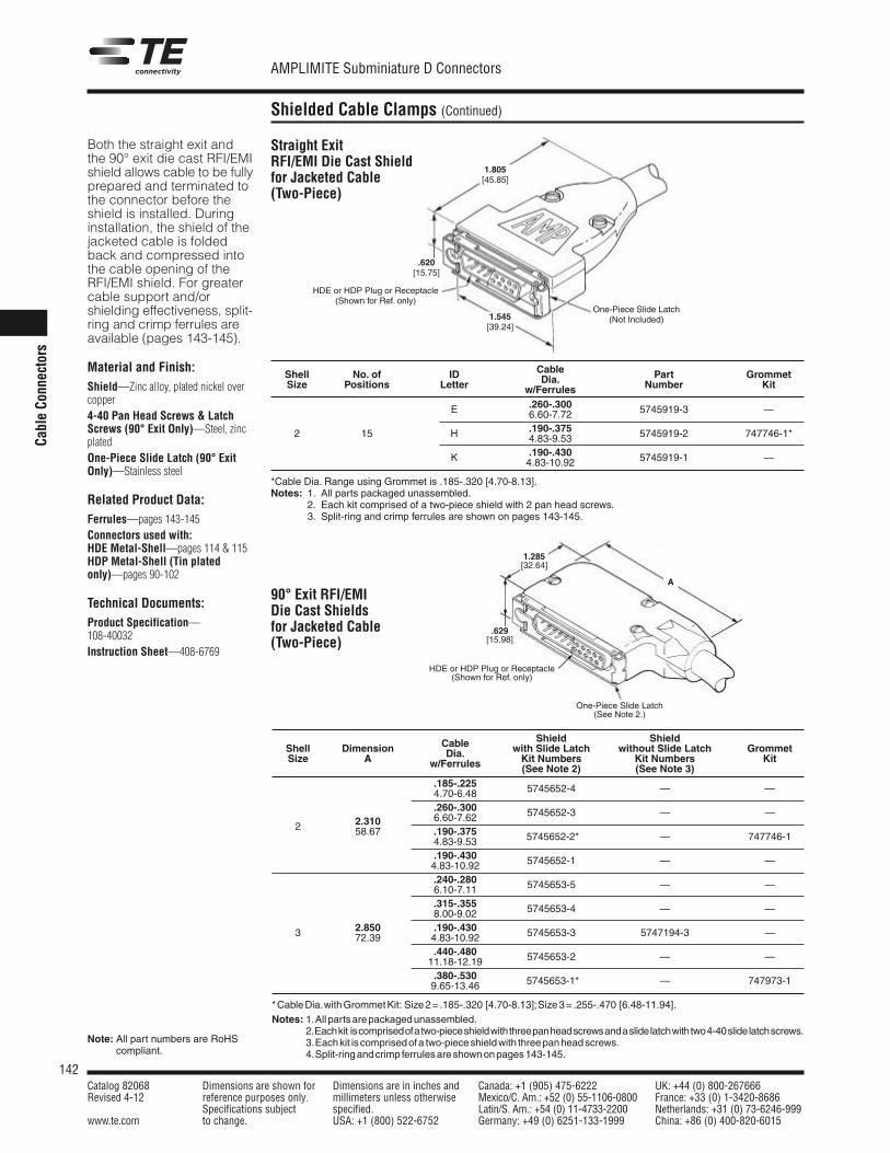
142Catalog 82068 Dimensions are shown for Dimensions are in inches and Canada: +1 (905) 475-6222 UK: +44 (0) 800-267666Revised 4-12 reference purposes only. millimeters unless otherwise Mexico/C. Am.: +52 (0) 55-1106-0800 France: +33 (0) 1-3420-8686
Specifications subject specified. Latin/S. Am.: +54 (0) 11-4733-2200 Netherlands: +31 (0) 73-6246-999www.te.com to change. USA: +1 (800) 522-6752 Germany: +49 (0) 6251-133-1999 China: +86 (0) 400-820-6015
AMPLIMITE Subminiature D Connectors
CableCo
nnectors
Shielded Cable Clamps (Continued)
Note: All part numbers are RoHScompliant.
Both the straight exit andthe 90° exit die cast RFI/EMIshield allows cable to be fullyprepared and terminated tothe connector before theshield is installed. Duringinstallation, the shield of thejacketed cable is foldedback and compressed intothe cable opening of theRFI/EMI shield. For greatercable support and/orshielding effectiveness, split-ring and crimp ferrules areavailable (pages 143-145).
Material and Finish:Shield—Zinc alloy, plated nickel overcopper4-40 Pan Head Screws & LatchScrews (90° Exit Only)—Steel, zincplatedOne-Piece Slide Latch (90° ExitOnly)—Stainless steel
Related Product Data:Ferrules—pages 143-145Connectors used with:HDE Metal-Shell—pages 114 & 115HDP Metal-Shell (Tin platedonly)—pages 90-102
Technical Documents:Product Specification—108-40032Instruction Sheet—408-6769
CableShell No. of ID Dia. Part GrommetSize Positions Letter w/Ferrules Number Kit
.260-.300E 6.60-7.72 5745919-3 —
2 15 .190-.375H 4.83-9.53 5745919-2 747746-1*
.190-.430K 4.83-10.92 5745919-1 —
*Cable Dia. Range using Grommet is .185-.320 [4.70-8.13].Notes: 1. All parts packaged unassembled.
2. Each kit comprised of a two-piece shield with 2 pan head screws.3. Split-ring and crimp ferrules are shown on pages 143-145.
Shield ShieldCable with Slide Latch without Slide Latch GrommetShell Dimension Dia. Kit Numbers Kit Numbers KitSize A w/Ferrules (See Note 2) (See Note 3).185-.2254.70-6.48 5745652-4 — —
.260-.3006.60-7.62 5745652-3 — —
2.310.190-.3752 58.674.83-9.53 5745652-2* — 747746-1
.190-.4304.83-10.92 5745652-1 — —
.240-.2806.10-7.11 5745653-5 — —
.315-.3558.00-9.02 5745653-4 — —
2.850 .190-.4303 72.39 4.83-10.92 5745653-3 5747194-3 —
.440-.48011.18-12.19 5745653-2 — —
.380-.5309.65-13.46 5745653-1* — 747973-1
*CableDia.withGrommetKit: Size2= .185-.320 [4.70-8.13];Size3= .255-.470 [6.48-11.94].Notes: 1.All partsarepackagedunassembled.
2.Eachkit iscomprisedofatwo-pieceshieldwiththreepanheadscrewsandaslidelatchwithtwo4-40slidelatchscrews.3.Eachkit is comprisedofa two-pieceshieldwith threepanheadscrews.4.Split-ringandcrimp ferrulesareshownonpages143-145.
90° Exit RFI/EMIDie Cast Shieldsfor Jacketed Cable(Two-Piece)
HDE or HDP Plug or Receptacle(Shown for Ref. only)
A
1.285[32.64]
1.805[45.85]
1.545[39.24]
HDE or HDP Plug or Receptacle(Shown for Ref. only)
One-Piece Slide Latch(Not Included)
One-Piece Slide Latch(See Note 2.)
.620[15.75]
.629[15.98]
Straight ExitRFI/EMI Die Cast Shieldfor Jacketed Cable(Two-Piece)
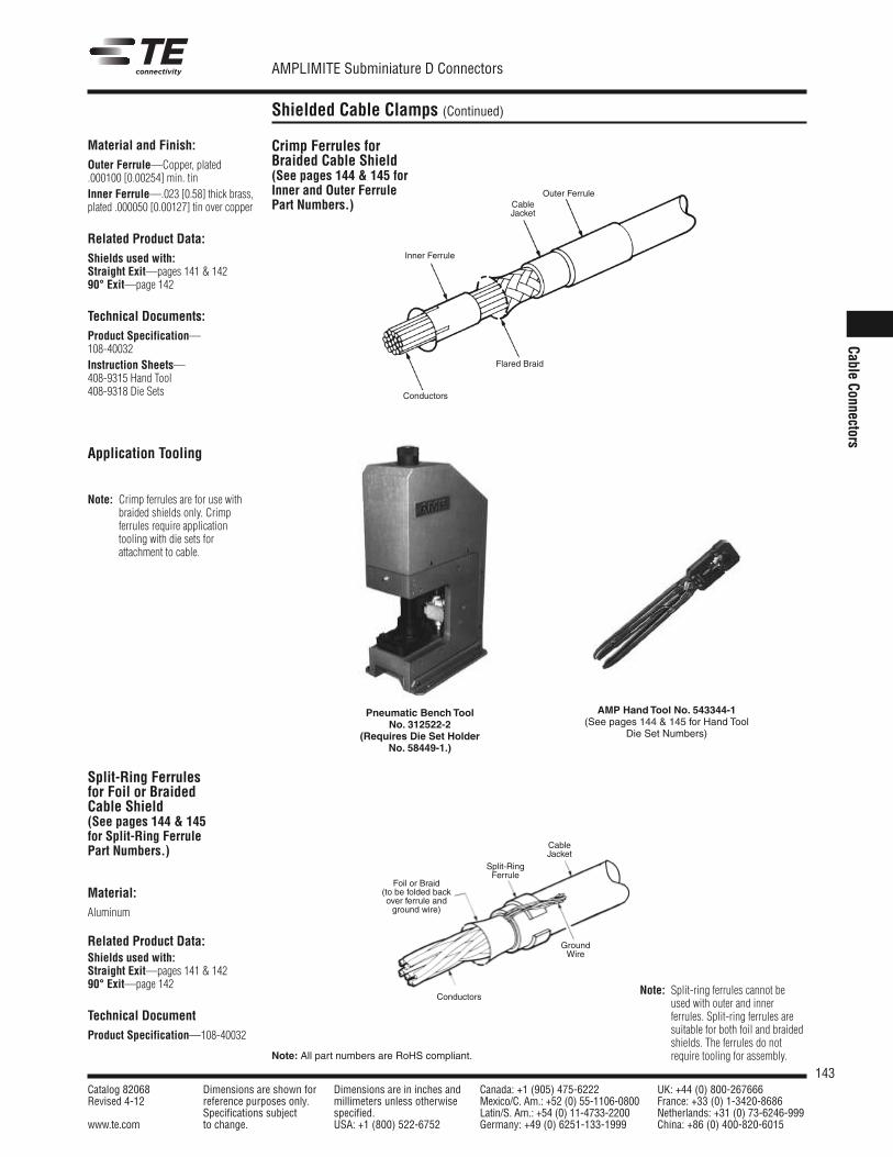
143Catalog 82068 Dimensions are shown for Dimensions are in inches and Canada: +1 (905) 475-6222 UK: +44 (0) 800-267666Revised 4-12 reference purposes only. millimeters unless otherwise Mexico/C. Am.: +52 (0) 55-1106-0800 France: +33 (0) 1-3420-8686
Specifications subject specified. Latin/S. Am.: +54 (0) 11-4733-2200 Netherlands: +31 (0) 73-6246-999www.te.com to change. USA: +1 (800) 522-6752 Germany: +49 (0) 6251-133-1999 China: +86 (0) 400-820-6015
AMPLIMITE Subminiature D Connectors
Note: All part numbers are RoHS compliant.
CableConnectors
Shielded Cable Clamps (Continued)
Material and Finish:Outer Ferrule—Copper, plated.000100 [0.00254] min. tinInner Ferrule—.023 [0.58] thick brass,plated .000050 [0.00127] tin over copper
Related Product Data:Shields used with:Straight Exit—pages 141 & 14290° Exit—page 142
Technical Documents:Product Specification—108-40032Instruction Sheets—408-9315 Hand Tool408-9318 Die Sets
Crimp Ferrules forBraided Cable Shield(See pages 144 & 145 forInner and Outer FerrulePart Numbers.)
Material:Aluminum
Related Product Data:Shields used with:Straight Exit—pages 141 & 14290° Exit—page 142
Technical DocumentProduct Specification—108-40032
Outer FerruleCableJacket
Inner Ferrule
Flared Braid
Conductors
Conductors
GroundWire
CableJacket
Split-RingFerrule
Foil or Braid(to be folded backover ferrule andground wire)
AMP HandTool No. 543344-1(See pages 144 & 145 for Hand Tool
Die Set Numbers)
Split-Ring Ferrulesfor Foil or BraidedCable Shield(See pages 144 & 145for Split-Ring FerrulePart Numbers.)
Note: Split-ring ferrules cannot beused with outer and innerferrules. Split-ring ferrules aresuitable for both foil and braidedshields. The ferrules do notrequire tooling for assembly.
Pneumatic BenchToolNo. 312522-2
(Requires Die Set HolderNo. 58449-1.)
Application Tooling
Note: Crimp ferrules are for use withbraided shields only. Crimpferrules require applicationtooling with die sets forattachment to cable.
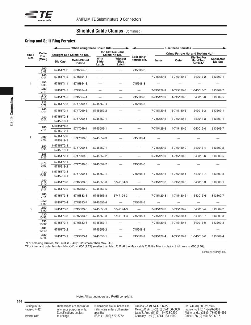
144Catalog 82068 Dimensions are shown for Dimensions are in inches and Canada: +1 (905) 475-6222 UK: +44 (0) 800-267666Revised 4-12 reference purposes only. millimeters unless otherwise Mexico/C. Am.: +52 (0) 55-1106-0800 France: +33 (0) 1-3420-8686
Specifications subject specified. Latin/S. Am.: +54 (0) 11-4733-2200 Netherlands: +31 (0) 73-6246-999www.te.com to change. USA: +1 (800) 522-6752 Germany: +49 (0) 6251-133-1999 China: +86 (0) 400-820-6015
AMPLIMITE Subminiature D Connectors
Note: All part numbers are RoHS compliant.
CableCo
nnectors
Shielded Cable Clamps (Continued)
Crimp and Split-Ring Ferrules
When using these Shield Kits Use these Ferrules90° Exit Die Cast
Straight Exit Shield Kit No. Shield Kit No. Crimp Ferrule No. andTooling No.**Cable
With Without Die Set ForShell Dia.
Metal-Plated Slide Slide
Split-Ring*HandTool ApplicatorSize (Max.)
Die Cast Plastic Latch Latch
Ferrule No. Inner Outer543344-1 Die Set
.2005.08 5745171-2 5745854-5 — — 745508-2 — — — —
.2406.10 5745171-5 5745854-1 — — — 7-745129-8 3-745130-8 543013-2 813809-1
.2501 6.35 5745171-1 5745854-3 — — 745508-3 — — — —
.2807.11 5745171-5 5745854-1 — — — 7-745129-9 4-745130-5 1-543013-7 813809-7
.3709.40 5745171-5 5745854-1 — — 745508-6 6-745129-9 4-745130-0 543013-6 813809-5
.2255.72 5745172-3 5747099-7 5745652-4 — 745508-3 — — — —
.2406.10 5745172-1 5747099-3 5745652-2 — — 7-745129-8 3-745130-8 543013-2 813809-1
.240 1-5745172-36.10 5747099-1 5745652-1 — — 7-745129-3 3-745130-8 543013-3 813809-1
5745919-1
.280 1-5745172-37.11 5747099-1 5745652-1 — — 7-745129-8 4-745130-5 1-543013-6 813809-7
5745919-1
2 .300 5745172-27.62 5747099-5 5745652-3 — 745508-4 — — — —
5745919-3
.350 1-5745172-38.90 5747099-1 5745652-1 — — 7-745129-2 3-745130-9 543013-4 813809-2
5745919-1
.3659.27 5745172-1 5747099-3 5745652-2 — — 6-745129-9 4-745130-0 543013-6 813809-5
.375 5745172-19.53 5747099-3 5745652-2 — 745508-6 — — — —
5745919-2
.430 1-5745172-310.92 5747099-1 5745652-1 — 745508-1 7-745129-1 4-745130-1 543013-7 813809-3
5745919-1
.2406.10 5745173-3 5745833-5 5745653-3 5747194-3 — 7-745129-3 3-745130-8 543013-3 813809-1
.2807.11 5745173-5 5745833-9 5745653-5 — 745508-4 — — — —
.2807.11 5745173-3 5745833-5 5745653-3 5747194-3 — 7-745129-8 4-745130-5 1-543013-6 813809-7
.3508.90 5745173-4 5745833-7 5745653-4 — 745508-5 — — — —
3 .3508.90 5745173-3 5745833-5 5745653-3 5747194-3 — 7-745129-2 3-745130-9 543013-4 813809-2
.43010.92 5745173-3 5745833-5 5745653-3 5747194-3 745508-1 7-745129-1 4-745130-1 543013-7 813809-3
.43010.92 5745173-1 5745833-1 5745653-1 — — 7-745129-5 4-745130-1 543013-8 813809-3
.48012.19 5745173-2 — 5745653-2 — 745508-8 — — — —
.53013.46 5745173-1 5745833-1 5745653-1 — 745508-9 7-745129-4 4-745130-2 1-543013-0 813809-4
**For split-ring ferrules, Min. O.D. is .040 [1.02] smaller than Max. O.D.**For inner and outer ferrules, Min. O.D. is .050 [1.27] smaller than Max. O.D. At the Max. cable O.D. the Min. insulation thickness is .060 [1.52].
Continued on Page 145
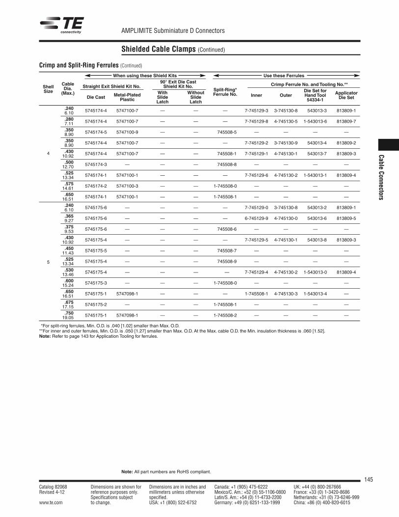
145Catalog 82068 Dimensions are shown for Dimensions are in inches and Canada: +1 (905) 475-6222 UK: +44 (0) 800-267666Revised 4-12 reference purposes only. millimeters unless otherwise Mexico/C. Am.: +52 (0) 55-1106-0800 France: +33 (0) 1-3420-8686
Specifications subject specified. Latin/S. Am.: +54 (0) 11-4733-2200 Netherlands: +31 (0) 73-6246-999www.te.com to change. USA: +1 (800) 522-6752 Germany: +49 (0) 6251-133-1999 China: +86 (0) 400-820-6015
AMPLIMITE Subminiature D Connectors
Note: All part numbers are RoHS compliant.
CableConnectors
Shielded Cable Clamps (Continued)
When using these Shield Kits Use these Ferrules90° Exit Die Cast
Straight Exit Shield Kit No. Shield Kit No. Crimp Ferrule No. andTooling No.**Cable
With Without Die Set forShell Dia.
Metal-Plated Slide Slide
Split-Ring*HandTool ApplicatorSize (Max.)
Die Cast Plastic Latch Latch
Ferrule No. Inner Outer54334-1 Die Set
.2406.10 5745174-4 5747100-7 — — — 7-745129-3 3-745130-8 543013-3 813809-1
.2807.11 5745174-4 5747100-7 — — — 7-745129-8 4-745130-5 1-543013-6 813809-7
.3508.90 5745174-5 5747100-9 — — 745508-5 — — — —
.3508.90 5745174-4 5747100-7 — — — 7-745129-2 3-745130-9 543013-4 813809-2
.4304 10.92 5745174-4 5747100-7 — — 745508-1 7-745129-1 4-745130-1 543013-7 813809-3
.50012.70 5745174-3 — — — 745508-8 — — — —
.52513.34 5745174-1 5747100-1 — — — 7-745129-6 4-745130-2 1-543013-1 813809-4
.57514.61 5745174-2 5747100-3 — — 1-745508-0 — — — —
.65016.51 5745174-1 5747100-1 — — 1-745508-1 — — — —
.2406.10 5745175-6 — — — — 7-745129-0 3-745130-8 543013-2 813809-1
.3659.27 5745175-6 — — — — 6-745129-9 4-745130-0 543013-6 813809-5
.3759.53 5745175-6 — — — 745508-6 — — — —
.43010.92 5745175-4 — — — — 7-745129-5 4-745130-1 543013-8 813809-3
.45011.43 5745175-5 — — — 745508-7 — — — —
5.525
13.34 5745175-4 — — — 745508-9 — — — —
.53013.46 5745175-4 — — — — 7-745129-4 4-745130-2 1-543013-0 813809-4
.60015.24 5745175-3 — — — 1-745508-0 — — — —
.65016.51 5745175-1 5747098-1 — — — 1-745508-1 4-745130-3 1-543013-4 —
.67517.15 5745175-2 — — — 1-745508-1 — — — —
.75019.05 5745175-1 5747098-1 — — 1-745508-2 — — — —
**For split-ring ferrules, Min. O.D. is .040 [1.02] smaller than Max. O.D.**For inner and outer ferrules, Min. O.D. is .050 [1.27] smaller than Max. O.D. At the Max. cable O.D. the Min. insulation thickness is .060 [1.52].Note: Refer to page 143 for Application Tooling for ferrules.
Crimp and Split-Ring Ferrules (Continued)
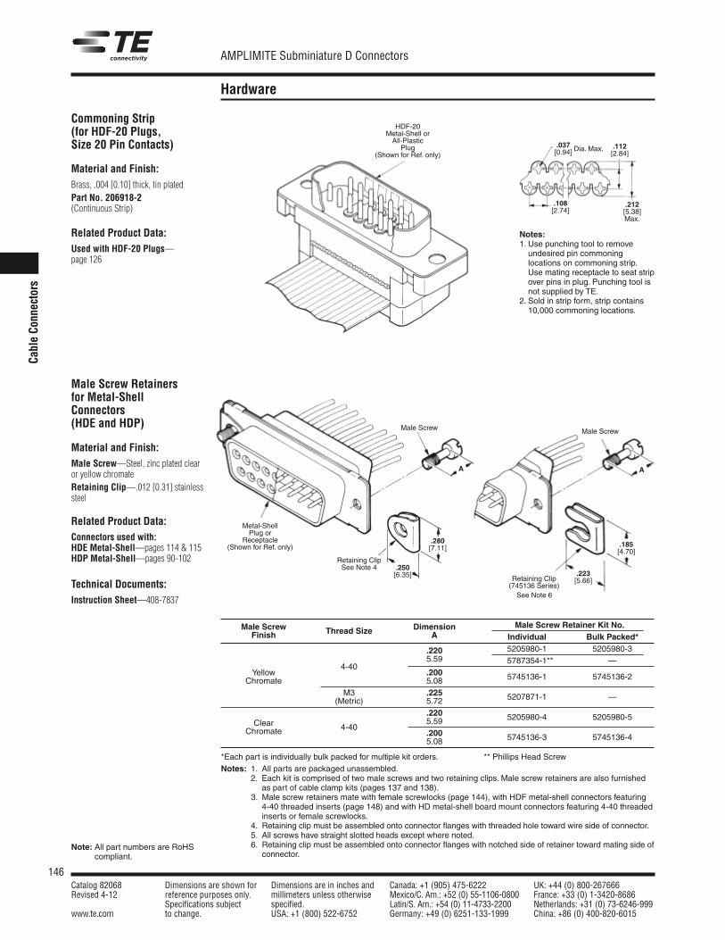
146Catalog 82068 Dimensions are shown for Dimensions are in inches and Canada: +1 (905) 475-6222 UK: +44 (0) 800-267666Revised 4-12 reference purposes only. millimeters unless otherwise Mexico/C. Am.: +52 (0) 55-1106-0800 France: +33 (0) 1-3420-8686
Specifications subject specified. Latin/S. Am.: +54 (0) 11-4733-2200 Netherlands: +31 (0) 73-6246-999www.te.com to change. USA: +1 (800) 522-6752 Germany: +49 (0) 6251-133-1999 China: +86 (0) 400-820-6015
AMPLIMITE Subminiature D Connectors
CableCo
nnectors
Hardware
Material and Finish:Male Screw—Steel, zinc plated clearor yellow chromateRetaining Clip—.012 [0.31] stainlesssteel
Related Product Data:Connectors used with:HDE Metal-Shell—pages 114 & 115HDP Metal-Shell—pages 90-102
Technical Documents:Instruction Sheet—408-7837
Male Screw Retainersfor Metal-ShellConnectors(HDE and HDP)
Male Screw Dimension Male Screw Retainer Kit No.Finish Thread Size A Individual Bulk Packed*
.220 5205980-1 5205980-35.59 5787354-1** —
Yellow4-40
.200Chromate 5.08 5745136-1 5745136-2
M3 .225(Metric) 5.72 5207871-1 —
.220Clear 5.59 5205980-4 5205980-5
Chromate 4-40.2005.08 5745136-3 5745136-4
*Each part is individually bulk packed for multiple kit orders. ** Phillips Head ScrewNotes: 1. All parts are packaged unassembled.
2. Each kit is comprised of two male screws and two retaining clips. Male screw retainers are also furnishedas part of cable clamp kits (pages 137 and 138).
Notes: 3. Male screw retainers mate with female screwlocks (page 144), with HDF metal-shell connectors featuring4-40 threaded inserts (page 148) and with HD metal-shell board mount connectors featuring 4-40 threadedinserts or female screwlocks.
Notes: 4. Retaining clip must be assembled onto connector flanges with threaded hole toward wire side of connector.Notes: 5. All screws have straight slotted heads except where noted.Notes: 6. Retaining clip must be assembled onto connector flanges with notched side of retainer toward mating side of
connector.
Male Screw
.223[5.66]
.185[4.70]
.280[7.11]
.250[6.35]
AA
Male Screw
Retaining ClipSee Note 4
Retaining Clip(745136 Series)
Metal-ShellPlug or
Receptacle(Shown for Ref. only)
Commoning Strip(for HDF-20 Plugs,Size 20 Pin Contacts)
Material and Finish:Brass, .004 [0.10] thick, tin platedPart No. 206918-2(Continuous Strip)
Related Product Data:Used with HDF-20 Plugs—page 126
Notes:1. Use punching tool to remove
undesired pin commoninglocations on commoning strip.Use mating receptacle to seat stripover pins in plug. Punching tool isnot supplied by TE.
2. Sold in strip form, strip contains10,000 commoning locations.
HDF-20Metal-Shell orAll-Plastic
Plug(Shown for Ref. only)
.037[0.94]
.112[2.84]
.108[2.74]
.212[5.38]Max.
Dia. Max.
See Note 6
Note: All part numbers are RoHScompliant.
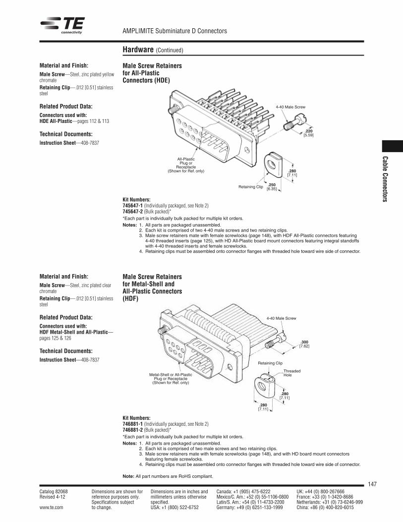
147Catalog 82068 Dimensions are shown for Dimensions are in inches and Canada: +1 (905) 475-6222 UK: +44 (0) 800-267666Revised 4-12 reference purposes only. millimeters unless otherwise Mexico/C. Am.: +52 (0) 55-1106-0800 France: +33 (0) 1-3420-8686
Specifications subject specified. Latin/S. Am.: +54 (0) 11-4733-2200 Netherlands: +31 (0) 73-6246-999www.te.com to change. USA: +1 (800) 522-6752 Germany: +49 (0) 6251-133-1999 China: +86 (0) 400-820-6015
AMPLIMITE Subminiature D Connectors
Note: All part numbers are RoHS compliant.
CableConnectors
Hardware (Continued)
Male Screw Retainersfor All-PlasticConnectors (HDE)
Material and Finish:Male Screw—Steel, zinc plated yellowchromateRetaining Clip—.012 [0.51] stainlesssteel
Related Product Data:Connectors used with:HDE All-Plastic—pages 112 & 113
Technical Documents:IInstruction Sheet—408-7837
Kit Numbers:745647-1 (Individually packaged, see Note 2)745647-2 (Bulk packed)**Each part is individually bulk packed for multiple kit orders.Notes: 1. All parts are packaged unassembled.
2. Each kit is comprised of two 4-40 male screws and two retaining clips.3. Male screw retainers mate with female screwlocks (page 148), with HDF All-Plastic connectors featuring
4-40 threaded inserts (page 125), with HD All-Plastic board mount connectors featuring integral standoffswith 4-40 threaded inserts and female screwlocks.
Notes: 4. Retaining clips must be assembled onto connector flanges with threaded hole toward wire side of connector.
Male Screw Retainersfor Metal-Shell andAll-Plastic Connectors(HDF)
Kit Numbers:746881-1 (Individually packaged, see Note 2)746881-2 (Bulk packed)**Each part is individually bulk packed for multiple kit orders.Notes: 1. All parts are packaged unassembled.
2. Each kit is comprised of two male screws and two retaining clips.3. Male screw retainers mate with female screwlocks (page 148), and with HD board mount connectors
featuring female screwlocks.Notes: 4. Retaining clips must be assembled onto connector flanges with threaded hole toward wire side of connector.
Material and Finish:Male Screw—Steel, zinc plated clearchromateRetaining Clip—.012 [0.51] stainlesssteel
Related Product Data:Connectors used with:HDF Metal-Shell and All-Plastic—pages 125 & 126
Technical Documents:Instruction Sheet—408-7837
All-PlasticPlug or
Receptacle(Shown for Ref. only)
Metal-Shell or All-PlasticPlug or Receptacle(Shown for Ref. only)
ThreadedHole
Retaining Clip
Retaining Clip
4-40 Male Screw
4-40 Male Screw
.300[7.62]
.280[7.11]
.280[7.11]
.250[6.35]
.280[7.11]
.220[5.59]
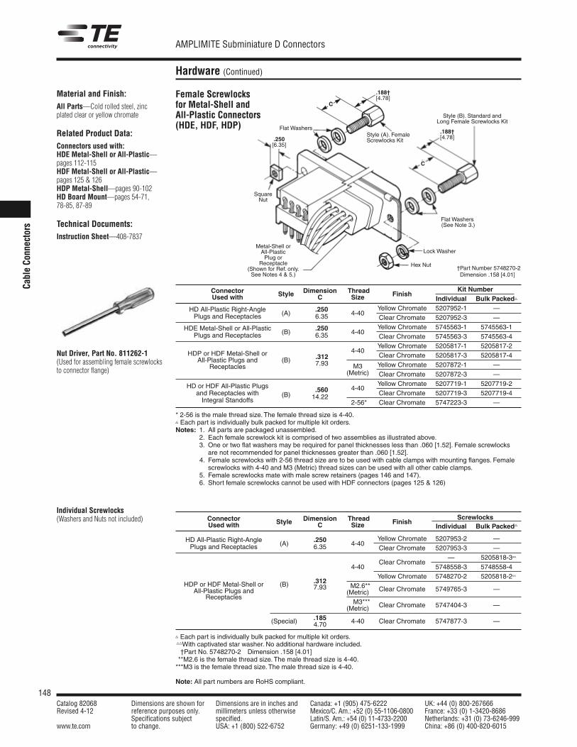
148Catalog 82068 Dimensions are shown for Dimensions are in inches and Canada: +1 (905) 475-6222 UK: +44 (0) 800-267666Revised 4-12 reference purposes only. millimeters unless otherwise Mexico/C. Am.: +52 (0) 55-1106-0800 France: +33 (0) 1-3420-8686
Specifications subject specified. Latin/S. Am.: +54 (0) 11-4733-2200 Netherlands: +31 (0) 73-6246-999www.te.com to change. USA: +1 (800) 522-6752 Germany: +49 (0) 6251-133-1999 China: +86 (0) 400-820-6015
AMPLIMITE Subminiature D Connectors
Note: All part numbers are RoHS compliant.
Cable Co
nnectors
Hardware (Continued)
Material and Finish:All Parts—Cold rolled steel, zincplated clear or yellow chromate
Related Product Data:Connectors used with:HDE Metal-Shell or All-Plastic—pages 112-115HDF Metal-Shell or All-Plastic—pages 125 & 126HDP Metal-Shell—pages 90-102HD Board Mount—pages 54-71, 78-85, 87-89
Technical Documents:Instruction Sheet—408-7837
Nut Driver, Part No. 811262-1(Used for assembling female screwlocksto connector flange)
Individual Screwlocks(Washers and Nuts not included)
Connector Dimension Thread Kit NumberUsed with Style C Size Finish
Individual Bulk Packed
HD All-Plastic Right-Angle .250 Yellow Chromate 5207952-1 —Plugs and Receptacles (A) 6.35 4-40
Clear Chromate 5207952-3 —
HDE Metal-Shell or All-Plastic .250 Yellow Chromate 5745563-1 5745563-1Plugs and Receptacles (B) 6.35 4-40
Clear Chromate 5745563-3 5745563-4Yellow Chromate 5205817-1 5205817-2
HDP or HDF Metal-Shell or .3124-40
Clear Chromate 5205817-3 5205817-4All-Plastic Plugs and (B) 7.93 M3 Yellow Chromate 5207872-1 —Receptacles
(Metric) Clear Chromate 5207872-3 —
HD or HDF All-Plastic Plugs 4-40Yellow Chromate 5207719-1 5207719-2
and Receptacles with .560 Clear Chromate 5207719-3 5207719-4Integral Standoffs
(B) 14.22*2-56* Clear Chromate 5747223-3 —
* 2-56 is the male thread size. The female thread size is 4-40. Each part is individually bulk packed for multiple kit orders.Notes: 1. All parts are packaged unassembled.
2. Each female screwlock kit is comprised of two assemblies as illustrated above.3. One or two flat washers may be required for panel thicknesses less than .060 [1.52]. Female screwlocks
are not recommended for panel thicknesses greater than .060 [1.52].Notes: 4. Female screwlocks with 2-56 thread size are to be used with cable clamps with mounting flanges. Female
screwlocks with 4-40 and M3 (Metric) thread sizes can be used with all other cable clamps.Notes: 5. Female screwlocks mate with male screw retainers (pages 146 and 147).
6. Short female screwlocks cannot be used with HDF connectors (pages 125 & 126)
Connector Dimension Thread ScrewlocksUsed with Style C Size Finish
Individual Bulk Packed
HD All-Plastic Right-Angle .250 Yellow Chromate 5207953-2 —Plugs and Receptacles (A) 6.35 4-40
Clear Chromate 5207953-3 —
Clear Chromate— 5205818-3
4-40 5748558-3 5748558-4
.312Yellow Chromate 5748270-2 5205818-2
HDP or HDF Metal-Shell or (B) 7.93 **M2.6**All-Plastic Plugs and (Metric) Clear Chromate 5749765-3 —
Receptacles***M3***(Metric) Clear Chromate 5747404-3 —
.185(Special) 4.70 4-40 Clear Chromate 5747877-3 —
Each part is individually bulk packed for multiple kit orders.With captivated star washer. No additional hardware included.†Part No. 5748270-2 Dimension .158 [4.01]
***M2.6 is the female thread size. The male thread size is 4-40.***M3 is the female thread size. The male thread size is 4-40.
Lock Washer
Flat Washers(See Note 3.)
Style (B). Standard andLong Female Screwlocks Kit
Metal-Shell orAll-PlasticPlug or
Receptacle(Shown for Ref. only.See Notes 4 & 5.)
Style (A). FemaleScrewlocks Kit
SquareNut
Hex Nut
Flat Washers.188†[4.78]
.188†[4.78]
.250[6.35]
C
C
Female Screwlocksfor Metal-Shell andAll-Plastic Connectors(HDE, HDF, HDP)
†Part Number 5748270-2Dimension .158 [4.01]
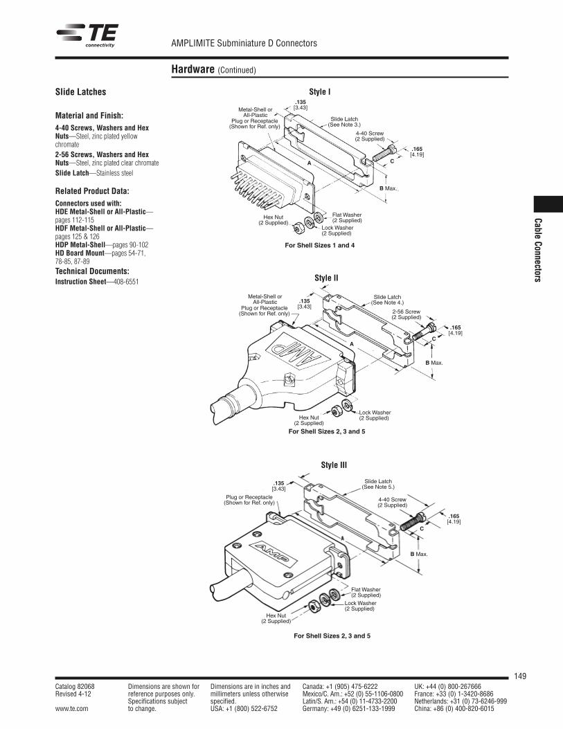
149Catalog 82068 Dimensions are shown for Dimensions are in inches and Canada: +1 (905) 475-6222 UK: +44 (0) 800-267666Revised 4-12 reference purposes only. millimeters unless otherwise Mexico/C. Am.: +52 (0) 55-1106-0800 France: +33 (0) 1-3420-8686
Specifications subject specified. Latin/S. Am.: +54 (0) 11-4733-2200 Netherlands: +31 (0) 73-6246-999www.te.com to change. USA: +1 (800) 522-6752 Germany: +49 (0) 6251-133-1999 China: +86 (0) 400-820-6015
AMPLIMITE Subminiature D Connectors
Cable Connectors
Hardware (Continued)
Slide Latches
Material and Finish:4-40 Screws, Washers and HexNuts—Steel, zinc plated yellowchromate2-56 Screws, Washers and HexNuts—Steel, zinc plated clear chromateSlide Latch—Stainless steel
Related Product Data:Connectors used with:HDE Metal-Shell or All-Plastic—pages 112-115HDF Metal-Shell or All-Plastic—pages 125 & 126HDP Metal-Shell—pages 90-102HD Board Mount—pages 54-71, 78-85, 87-89Technical Documents:Instruction Sheet—408-6551
Style I
Style II
For Shell Sizes 1 and 4
For Shell Sizes 2, 3 and 5
Style III
For Shell Sizes 2, 3 and 5
Metal-Shell or All-Plastic
Plug or Receptacle(Shown for Ref. only)
Slide Latch(See Note 3.)
4-40 Screw(2 Supplied)
Lock Washer(2 Supplied)
Flat Washer(2 Supplied)
Hex Nut(2 Supplied)
.165[4.19]
C
B Max.
.135[3.43]
Lock Washer(2 Supplied)
Metal-Shell or All-Plastic
Plug or Receptacle(Shown for Ref. only)
.135[3.43]
B Max.
Slide Latch(See Note 4.)
2-56 Screw(2 Supplied)
Lock Washer(2 Supplied)
Flat Washer(2 Supplied)
Hex Nut(2 Supplied)
.165[4.19]
.165[4.19]
B Max.
Slide Latch(See Note 5.)
4-40 Screw(2 Supplied)
Hex Nut(2 Supplied)
C
Plug or Receptacle(Shown for Ref. only)
.135[3.43]
C
A
A
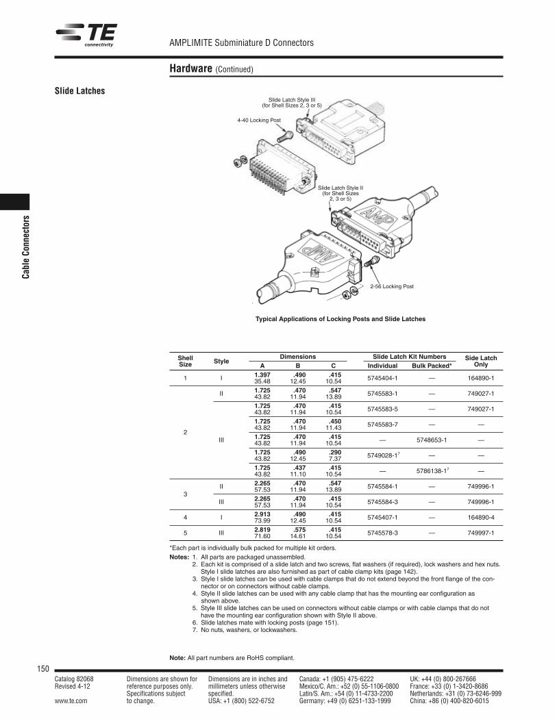
150Catalog 82068 Dimensions are shown for Dimensions are in inches and Canada: +1 (905) 475-6222 UK: +44 (0) 800-267666Revised 4-12 reference purposes only. millimeters unless otherwise Mexico/C. Am.: +52 (0) 55-1106-0800 France: +33 (0) 1-3420-8686
Specifications subject specified. Latin/S. Am.: +54 (0) 11-4733-2200 Netherlands: +31 (0) 73-6246-999www.te.com to change. USA: +1 (800) 522-6752 Germany: +49 (0) 6251-133-1999 China: +86 (0) 400-820-6015
AMPLIMITE Subminiature D Connectors
Note: All part numbers are RoHS compliant.
Cable Co
nnectors
Hardware (Continued)
Slide Latches
Shell Dimensions Slide Latch Kit Numbers Side LatchSize Style
A B C Individual Bulk Packed* Only
1.397 .490 .4151 I 35.48 12.45 10.54 5745404-1 — 164890-1
1.725 .470 .547II 43.82 11.94 13.89 5745583-1 — 749027-1
1.725 .470 .41543.82 11.94 10.54 5745583-5 — 749027-1
1.725 .470 .450
243.82 11.94 11.43 5745583-7 — —
1.725 .470 .415III 43.82 11.94 10.54 — 5748653-1 —
1.725 .490 .29043.82 12.45 7.37 5749028-17 — —
1.725 .437 .41543.82 11.10 10.54 — 5786138-17 —
2.265 .470 .547II 57.53 11.94 13.89 5745584-1 — 749996-13
2.265 .470 .415III 57.53 11.94 10.54 5745584-3 — 749996-1
2.913 .490 .4154 I 73.99 12.45 10.54 5745407-1 — 164890-4
2.819 .575 .4155 III 71.60 14.61 10.54 5745578-3 — 749997-1
*Each part is individually bulk packed for multiple kit orders.Notes: 1. All parts are packaged unassembled.
2. Each kit is comprised of a slide latch and two screws, flat washers (if required), lock washers and hex nuts.Style I slide latches are also furnished as part of cable clamp kits (page 142).
Notes: 3. Style I slide latches can be used with cable clamps that do not extend beyond the front flange of the con-nector or on connectors without cable clamps.
Notes: 4. Style II slide latches can be used with any cable clamp that has the mounting ear configuration asshown above.
5. Style III slide latches can be used on connectors without cable clamps or with cable clamps that do nothave the mounting ear configuration shown with Style II above.
Notes: 6. Slide latches mate with locking posts (page 151).Notes: 7. No nuts, washers, or lockwashers.
Typical Applications of Locking Posts and Slide Latches
Typical Applications of Locking Posts and Slide Latches
Slide Latch Style III(for Shell Sizes 2, 3 or 5)
4-40 Locking Post
2-56 Locking Post
Slide Latch Style II(for Shell Sizes
2, 3 or 5)
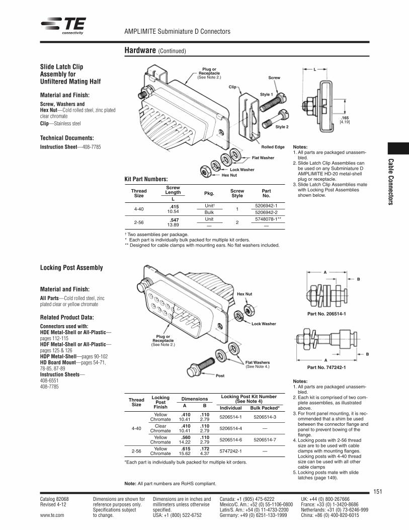
151Catalog 82068 Dimensions are shown for Dimensions are in inches and Canada: +1 (905) 475-6222 UK: +44 (0) 800-267666Revised 4-12 reference purposes only. millimeters unless otherwise Mexico/C. Am.: +52 (0) 55-1106-0800 France: +33 (0) 1-3420-8686
Specifications subject specified. Latin/S. Am.: +54 (0) 11-4733-2200 Netherlands: +31 (0) 73-6246-999www.te.com to change. USA: +1 (800) 522-6752 Germany: +49 (0) 6251-133-1999 China: +86 (0) 400-820-6015
AMPLIMITE Subminiature D Connectors
Note: All part numbers are RoHS compliant.
Cable Connectors
Hardware (Continued)
Slide Latch ClipAssembly for Unfiltered Mating Half
Material and Finish:Screw, Washers and Hex Nut—Cold rolled steel, zinc platedclear chromateClip—Stainless steel
Technical Documents:Instruction Sheet—408-7785 Notes:
1. All parts are packaged unassem-bled.
2. Slide Latch Clip Assemblies canbe used on any Subminiature DAMPLIMITE HD-20 metal-shellplug or receptacle.
3. Slide Latch Clip Assemblies matewith Locking Post Assembliesshown below.
ThreadScrew
Screw PartSize
Length Pkg. Style No.L
4-40 .415 Unit†1
5206942-110.54 Bulk 5206942-2
2-56 .547 Unit2
5748078-1**13.89 — —
† Two assemblies per package.* Each part is individually bulk packed for multiple kit orders.** Designed for cable clamps with mounting ears. No flat washers included.
Hex Nut
Lock Washer
Flat Washers(See Note 4.)
Plug orReceptacle(See Note 2.)
Post
Hex Nut
Clip
Rolled Edge
Lock Washer
Flat Washer
Screw
Plug orReceptacle(See Note 2.)
L
.165[4.19]
Thread Locking Locking Post Kit Number
Size PostDimensions (See Note 4)
Finish A B Individual Bulk Packed*Yellow .410 .110 5206514-1 5206514-3Chromate 10.41 2.79
4-40 Clear .410 .110 5206514-4 —Chromate 10.41 2.79Yellow .560 .110 5206514-6 5206514-7Chromate 14.22 2.79Yellow .615 .1722-56 Chromate 15.62 4.37 5747242-1 —
*Each part is individually bulk packed for multiple kit orders.
A
A
B
B
Part No. 206514-1
Part No. 747242-1
Locking Post Assembly
Material and Finish:All Parts—Cold rolled steel, zincplated clear or yellow chromate
Related Product Data:Connectors used with:HDE Metal-Shell or All-Plastic—pages 112-115HDF Metal-Shell or All-Plastic—pages 125 & 126HDP Metal-Shell—pages 90-102HD Board Mount—pages 54-71, 78-85, 87-89Instruction Sheets—408-6551408-7785
Style 1
Style 2
Kit Part Numbers:
Notes:1. All parts are packaged unassem-
bled.2. Each kit is comprised of two com-
plete assemblies, as illustratedabove.
3. For front panel mounting, it is rec-ommended that a shim be usedbetween the connector flange andpanel to prevent bowing of theflange.
4. Locking posts with 2-56 threadsize are to be used with cableclamps with mounting flanges.Locking posts with 4-40 threadsize can be used with all othercable clamps
5. Locking posts mate with slidelatches (page 149).
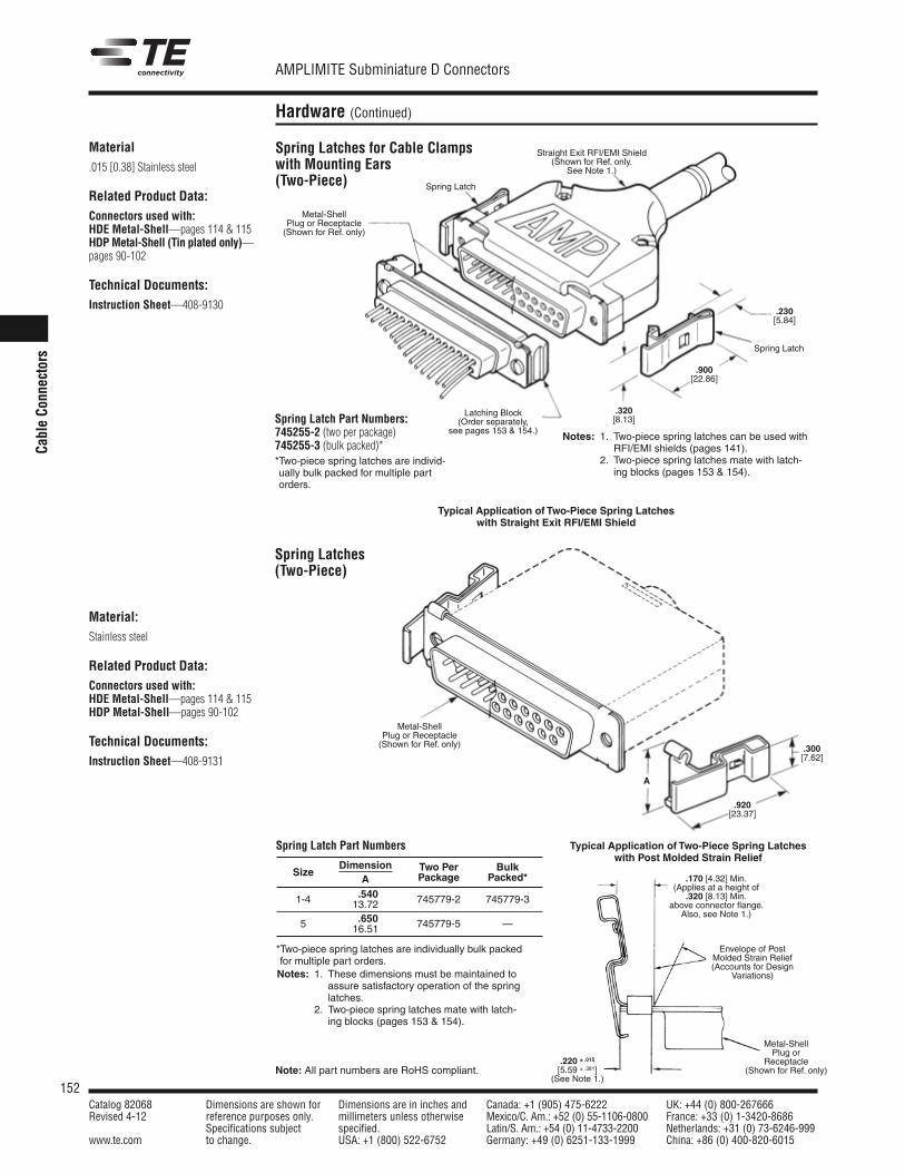
152Catalog 82068 Dimensions are shown for Dimensions are in inches and Canada: +1 (905) 475-6222 UK: +44 (0) 800-267666Revised 4-12 reference purposes only. millimeters unless otherwise Mexico/C. Am.: +52 (0) 55-1106-0800 France: +33 (0) 1-3420-8686
Specifications subject specified. Latin/S. Am.: +54 (0) 11-4733-2200 Netherlands: +31 (0) 73-6246-999www.te.com to change. USA: +1 (800) 522-6752 Germany: +49 (0) 6251-133-1999 China: +86 (0) 400-820-6015
AMPLIMITE Subminiature D Connectors
Note: All part numbers are RoHS compliant.
Cable Co
nnectors
Hardware (Continued)
Material.015 [0.38] Stainless steel
Related Product Data:Connectors used with:HDE Metal-Shell—pages 114 & 115HDP Metal-Shell (Tin plated only)—pages 90-102
Technical Documents:Instruction Sheet—408-9130
Spring Latch Part Numbers:745255-2 (two per package)745255-3 (bulk packed)**Two-piece spring latches are individ-ually bulk packed for multiple partorders.
Notes: 1. Two-piece spring latches can be used withRFI/EMI shields (pages 141).
Notes: 2. Two-piece spring latches mate with latch-ing blocks (pages 153 & 154).
Typical Application of Two-Piece Spring Latcheswith Straight Exit RFI/EMI Shield
Typical Application of Two-Piece Spring Latcheswith Post Molded Strain Relief
Spring Latches(Two-Piece)
Material:Stainless steel
Related Product Data:Connectors used with:HDE Metal-Shell—pages 114 & 115HDP Metal-Shell—pages 90-102
Technical Documents:Instruction Sheet—408-9131
*Two-piece spring latches are individually bulk packedfor multiple part orders.Notes: 1. These dimensions must be maintained to
assure satisfactory operation of the springlatches.
Notes: 2. Two-piece spring latches mate with latch-ing blocks (pages 153 & 154).
Spring Latch
.230[5.84]
.320[8.13]
Metal-ShellPlug or Receptacle(Shown for Ref. only)
Latching Block(Order separately,
see pages 153 & 154.)
Straight Exit RFI/EMI Shield(Shown for Ref. only.
See Note 1.)
Metal-ShellPlug or Receptacle(Shown for Ref. only)
A
.300[7.62]
.920[23.37]
.170 [4.32] Min.(Applies at a height of
.320 [8.13] Min.above connector flange.
Also, see Note 1.)
Envelope of PostMolded Strain Relief(Accounts for Design
Variations)
.220 ± .015[5.59 ± .381]
(See Note 1.)
.900[22.86]
Spring Latch
Dimension Two Per BulkSizeA Package Packed*
1-4 .540 745779-2 745779-313.72
5 .650 745779-5 —16.51
Spring Latch Part Numbers
Metal-ShellPlug or
Receptacle(Shown for Ref. only)
Spring Latches for Cable Clampswith Mounting Ears(Two-Piece)
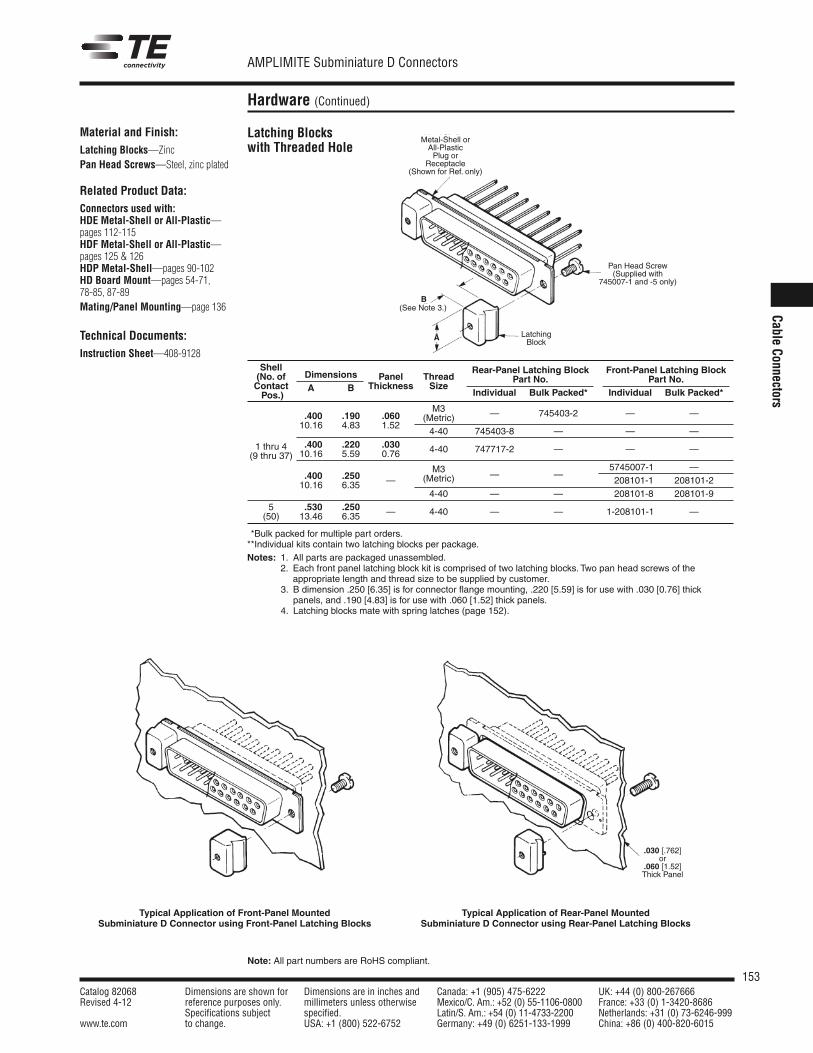
153Catalog 82068 Dimensions are shown for Dimensions are in inches and Canada: +1 (905) 475-6222 UK: +44 (0) 800-267666Revised 4-12 reference purposes only. millimeters unless otherwise Mexico/C. Am.: +52 (0) 55-1106-0800 France: +33 (0) 1-3420-8686
Specifications subject specified. Latin/S. Am.: +54 (0) 11-4733-2200 Netherlands: +31 (0) 73-6246-999www.te.com to change. USA: +1 (800) 522-6752 Germany: +49 (0) 6251-133-1999 China: +86 (0) 400-820-6015
AMPLIMITE Subminiature D Connectors
Note: All part numbers are RoHS compliant.
Cable Connectors
Hardware (Continued)
Material and Finish:Latching Blocks—ZincPan Head Screws—Steel, zinc plated
Related Product Data:Connectors used with:HDE Metal-Shell or All-Plastic—pages 112-115HDF Metal-Shell or All-Plastic—pages 125 & 126HDP Metal-Shell—pages 90-102HD Board Mount—pages 54-71, 78-85, 87-89Mating/Panel Mounting—page 136
Technical Documents:Instruction Sheet—408-9128
Latching Blockswith Threaded Hole
Typical Application of Front-Panel MountedSubminiature D Connector using Front-Panel Latching Blocks
Typical Application of Rear-Panel MountedSubminiature D Connector using Rear-Panel Latching Blocks
Metal-Shell orAll-PlasticPlug or
Receptacle(Shown for Ref. only)
LatchingBlock
B
A
.030 [.762]or
.060 [1.52]Thick Panel
Shell(No. of Dimensions Panel Thread
Rear-Panel Latching Block Front-Panel Latching Block
Contact Thickness SizePart No. Part No.
Pos.)A B Individual Bulk Packed* Individual Bulk Packed*
M3.400 .190 .060 (Metric) — 745403-2 — —
10.16 4.83 1.524-40 745403-8 — — —
1 thru 4 .400 .220 .030(9 thru 37) 10.16 5.59 0.76 4-40 747717-2 — — —
M3 5745007-1 —.400 .250 — (Metric) — —
208101-1 208101-210.16 6.354-40 — — 208101-8 208101-9
5 .530 .250(50) 13.46 6.35 — 4-40 — — 1-208101-1 —
**Bulk packed for multiple part orders.**Individual kits contain two latching blocks per package.Notes: 1. All parts are packaged unassembled.
2. Each front panel latching block kit is comprised of two latching blocks. Two pan head screws of the appropriate length and thread size to be supplied by customer.
Notes: 3. B dimension .250 [6.35] is for connector flange mounting, .220 [5.59] is for use with .030 [0.76] thick panels, and .190 [4.83] is for use with .060 [1.52] thick panels.
Notes: 4. Latching blocks mate with spring latches (page 152).
Pan Head Screw(Supplied with
745007-1 and -5 only)
(See Note 3.)
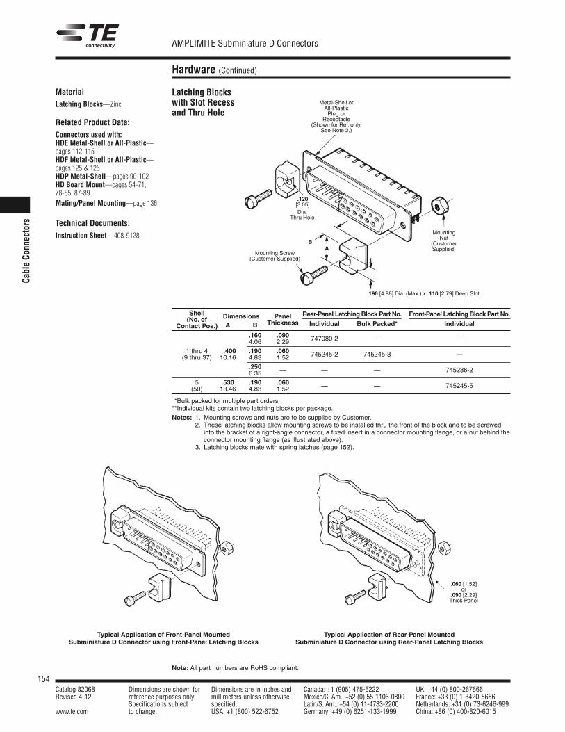
154Catalog 82068 Dimensions are shown for Dimensions are in inches and Canada: +1 (905) 475-6222 UK: +44 (0) 800-267666Revised 4-12 reference purposes only. millimeters unless otherwise Mexico/C. Am.: +52 (0) 55-1106-0800 France: +33 (0) 1-3420-8686
Specifications subject specified. Latin/S. Am.: +54 (0) 11-4733-2200 Netherlands: +31 (0) 73-6246-999www.te.com to change. USA: +1 (800) 522-6752 Germany: +49 (0) 6251-133-1999 China: +86 (0) 400-820-6015
AMPLIMITE Subminiature D Connectors
Note: All part numbers are RoHS compliant.
Cable Co
nnectors
Hardware (Continued)
Latching Blockswith Slot Recessand Thru Hole
MaterialLatching Blocks—Zinc
Related Product Data:Connectors used with:HDE Metal-Shell or All-Plastic—pages 112-115HDF Metal-Shell or All-Plastic—pages 125 & 126HDP Metal-Shell—pages 90-102HD Board Mount—pages 54-71, 78-85, 87-89Mating/Panel Mounting—page 136
Technical Documents:Instruction Sheet—408-9128
Typical Application of Front-Panel MountedSubminiature D Connector using Front-Panel Latching Blocks
Typical Application of Rear-Panel MountedSubminiature D Connector using Rear-Panel Latching Blocks
Metal-Shell orAll-PlasticPlug or
Receptacle(Shown for Ref. only,
See Note 2.)
Mounting Screw(Customer Supplied)
.196 [4.98] Dia. (Max.) x .110 [2.79] Deep Slot
MountingNut
(CustomerSupplied)A
B
.060 [1.52]or
.090 [2.29]Thick Panel
Shell(No. of Dimensions Panel Rear-Panel Latching Block Part No. Front-Panel Latching Block Part No.
Contact Pos.) A B Thickness Individual Bulk Packed* Individual
.160 .0904.06 2.29 747080-2 — —
1 thru 4 1.400 .190 .060(9 thru 37) 10.16 4.83 1.52 745245-2 745245-3 —
.2506.35 — — — 745286-2
5 .530 .190 .060(50) 13.46 4.83 1.52 — — 745245-5
**Bulk packed for multiple part orders.**Individual kits contain two latching blocks per package.Notes: 1. Mounting screws and nuts are to be supplied by Customer.
2. These latching blocks allow mounting screws to be installed thru the front of the block and to be screwedinto the bracket of a right-angle connector, a fixed insert in a connector mounting flange, or a nut behind theconnector mounting flange (as illustrated above).
Notes: 3. Latching blocks mate with spring latches (page 152).
.120[3.05]Dia.
Thru Hole
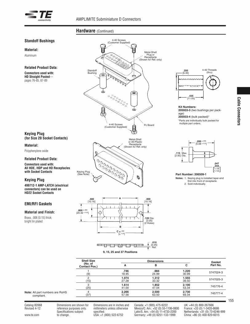
155Catalog 82068 Dimensions are shown for Dimensions are in inches and Canada: +1 (905) 475-6222 UK: +44 (0) 800-267666Revised 4-12 reference purposes only. millimeters unless otherwise Mexico/C. Am.: +52 (0) 55-1106-0800 France: +33 (0) 1-3420-8686
Specifications subject specified. Latin/S. Am.: +54 (0) 11-4733-2200 Netherlands: +31 (0) 73-6246-999www.te.com to change. USA: +1 (800) 522-6752 Germany: +49 (0) 6251-133-1999 China: +86 (0) 400-820-6015
AMPLIMITE Subminiature D Connectors
Cable Connectors
Note: All part numbers are RoHScompliant.
Hardware (Continued)
Standoff Bushings
Material:
Aluminum
Related Product Data:Connectors used with:HD Straight Posted—pages 76-85, 87-89
Kit Numbers:205933-3 (two bushings per pack-age)205933-4 (bulk packed)**Parts are individually bulk packed formultiple part orders.
Keying Plug(for Size 20 Socket Contacts)
Part Number: 206509-1Notes: 1. Keying plug is installed taper-end
first into front of receptacle.Notes: 2. Sold individually.
Material:Polyphenylene oxide
Related Product Data:Connectors used with:All HDE, HDP and HD Receptacleswith Socket Contacts
Keying Plug499712-1 AMP-LATCH (electricalconnectors) can be used on HD22 Socket Contacts
4-40 Screws(Customer Supplied)
Standoff Bushing
Pc Board
.250[6.35]
.435[11.05]
4-40 Threads(thru)
Keying Plug(See Note)
.400[10.16]
.120 Dia.[3.05]
(2 Holes)
.010[0.25]Ref.
.400[10.16]
B
A
C ± .010C [± 0.25]
.800 ± .010[20.32 ± 0.25]
9, 15, 25 and 37 Positions
Shell Size(No. of
Dimensions Gasket
Contact Pos.) A B C Part No.
1 .746 .984 1.220(9) 18.95 24.99 30.99 5747024-3
2 1.074 1.312 1.555(15) 27.28 33.32 39.50 5747025-3
3 1.614 1.852 2.100(25) 41.00 47.04 53.34 745776-4
4 2.266 2.500 2.730(37) 57.56 63.50 69.34 745777-4
EMI/RFI Gaskets
Material and Finish:Brass, .006 [0.15] thick; bright tin plated
Metal-Shellor All-PlasticReceptacle
(Shown for Ref. only)
4-40 Screws(Customer Supplied)
.200 ± .010[5.08 ± 0.25]
.047
.0441.191.12]
].115[2.92]
Max.Dia.
Metal-ShellPlug or
Receptacle(Shown for Ref. only)
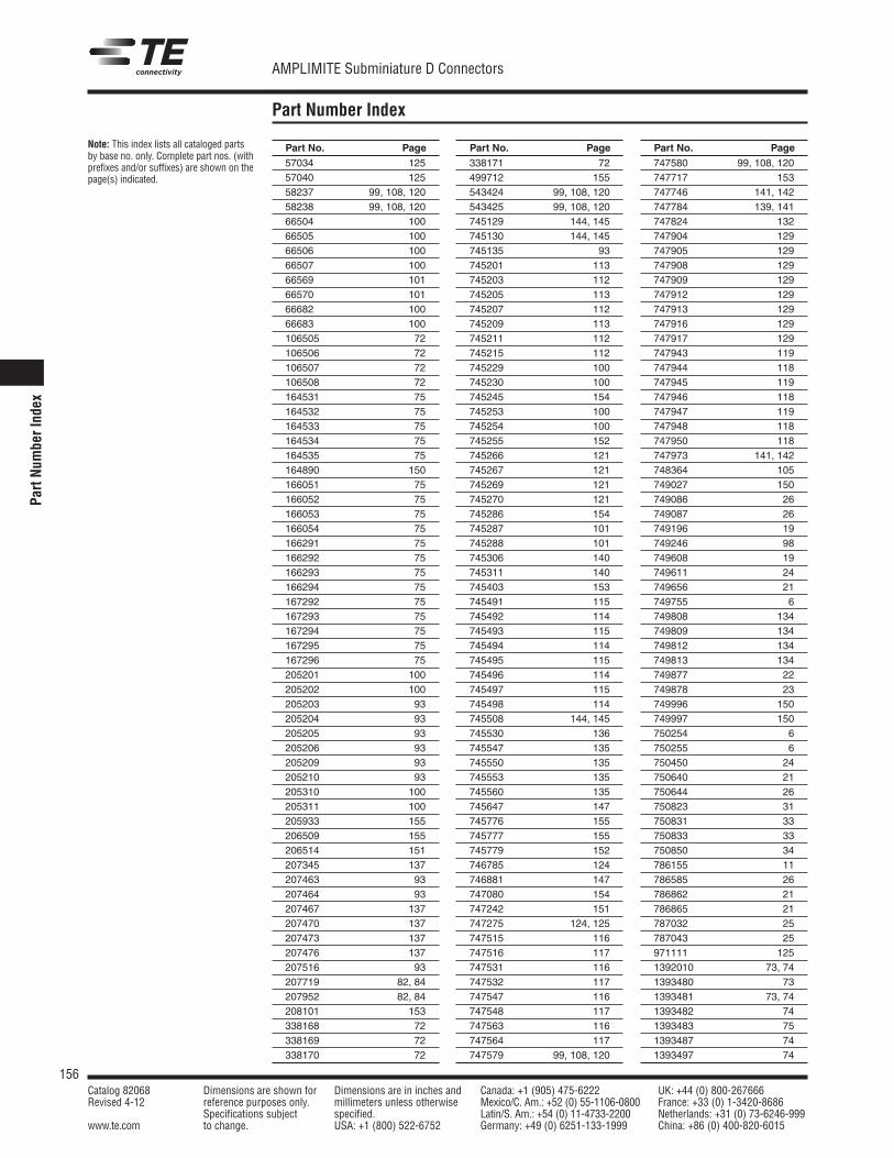
57034 12557040 12558237 99, 108, 12058238 99, 108, 12066504 10066505 10066506 10066507 10066569 10166570 10166682 10066683 100106505 72106506 72106507 72106508 72164531 75164532 75164533 75164534 75164535 75164890 150166051 75166052 75166053 75166054 75166291 75166292 75166293 75166294 75167292 75167293 75167294 75167295 75167296 75205201 100205202 100205203 93205204 93205205 93205206 93205209 93205210 93205310 100205311 100205933 155206509 155206514 151207345 137207463 93207464 93207467 137207470 137207473 137207476 137207516 93207719 82, 84207952 82, 84208101 153338168 72338169 72338170 72
Part No. Page338171 72499712 155543424 99, 108, 120543425 99, 108, 120745129 144, 145745130 144, 145745135 93745201 113745203 112745205 113745207 112745209 113745211 112745215 112745229 100745230 100745245 154745253 100745254 100745255 152745266 121745267 121745269 121745270 121745286 154745287 101745288 101745306 140745311 140745403 153745491 115745492 114745493 115745494 114745495 115745496 114745497 115745498 114745508 144, 145745530 136745547 135745550 135745553 135745560 135745647 147745776 155745777 155745779 152746785 124746881 147747080 154747242 151747275 124, 125747515 116747516 117747531 116747532 117747547 116747548 117747563 116747564 117747579 99, 108, 120
Part No. Page747580 99, 108, 120747717 153747746 141, 142747784 139, 141747824 132747904 129747905 129747908 129747909 129747912 129747913 129747916 129747917 129747943 119747944 118747945 119747946 118747947 119747948 118747950 118747973 141, 142748364 105749027 150749086 26749087 26749196 19749246 98749608 19749611 24749656 21749755 6749808 134749809 134749812 134749813 134749877 22749878 23749996 150749997 150750254 6750255 6750450 24750640 21750644 26750823 31750831 33750833 33750850 34786155 11786585 26786862 21786865 21787032 25787043 25971111 1251392010 73, 741393480 731393481 73, 741393482 741393483 751393487 741393497 74
Part No. Page
156Catalog 82068 Dimensions are shown for Dimensions are in inches and Canada: +1 (905) 475-6222 UK: +44 (0) 800-267666Revised 4-12 reference purposes only. millimeters unless otherwise Mexico/C. Am.: +52 (0) 55-1106-0800 France: +33 (0) 1-3420-8686
Specifications subject specified. Latin/S. Am.: +54 (0) 11-4733-2200 Netherlands: +31 (0) 73-6246-999www.te.com to change. USA: +1 (800) 522-6752 Germany: +49 (0) 6251-133-1999 China: +86 (0) 400-820-6015
Note: This index lists all cataloged partsby base no. only. Complete part nos. (withprefixes and/or suffixes) are shown on thepage(s) indicated.
Part Number Index
AMPLIMITE Subminiature D Connectors
Part
Num
berI
ndex
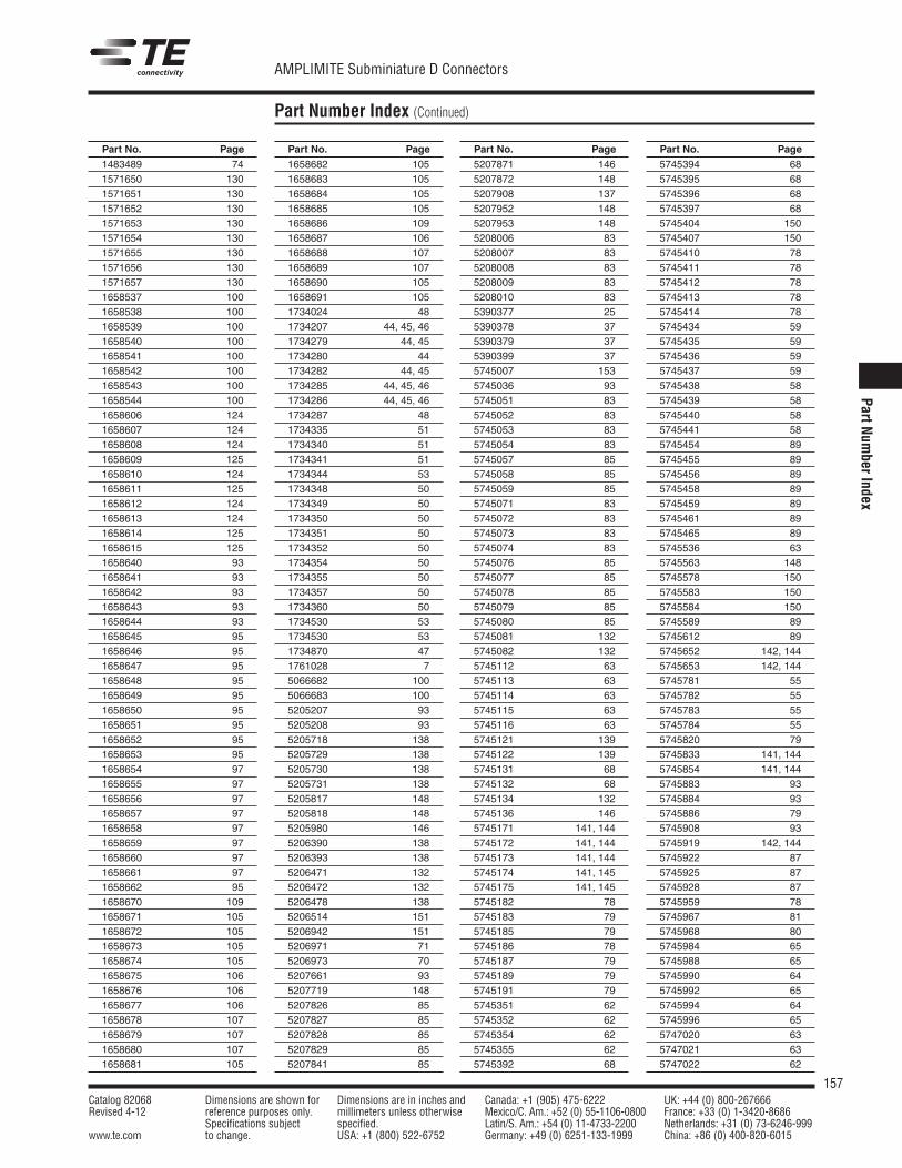
1483489 741571650 1301571651 1301571652 1301571653 1301571654 1301571655 1301571656 1301571657 1301658537 1001658538 1001658539 1001658540 1001658541 1001658542 1001658543 1001658544 1001658606 1241658607 1241658608 1241658609 1251658610 1241658611 1251658612 1241658613 1241658614 1251658615 1251658640 931658641 931658642 931658643 931658644 931658645 951658646 951658647 951658648 951658649 951658650 951658651 951658652 951658653 951658654 971658655 971658656 971658657 971658658 971658659 971658660 971658661 971658662 951658670 1091658671 1051658672 1051658673 1051658674 1051658675 1061658676 1061658677 1061658678 1071658679 1071658680 1071658681 105
Part No. Page1658682 1051658683 1051658684 1051658685 1051658686 1091658687 1061658688 1071658689 1071658690 1051658691 1051734024 481734207 44, 45, 461734279 44, 451734280 441734282 44, 451734285 44, 45, 461734286 44, 45, 461734287 481734335 511734340 511734341 511734344 531734348 501734349 501734350 501734351 501734352 501734354 501734355 501734357 501734360 501734530 531734530 531734870 471761028 75066682 1005066683 1005205207 935205208 935205718 1385205729 1385205730 1385205731 1385205817 1485205818 1485205980 1465206390 1385206393 1385206471 1325206472 1325206478 1385206514 1515206942 1515206971 715206973 705207661 935207719 1485207826 855207827 855207828 855207829 855207841 85
Part No. Page5207871 1465207872 1485207908 1375207952 1485207953 1485208006 835208007 835208008 835208009 835208010 835390377 255390378 375390379 375390399 375745007 1535745036 935745051 835745052 835745053 835745054 835745057 855745058 855745059 855745071 835745072 835745073 835745074 835745076 855745077 855745078 855745079 855745080 855745081 1325745082 1325745112 635745113 635745114 635745115 635745116 635745121 1395745122 1395745131 685745132 685745134 1325745136 1465745171 141, 1445745172 141, 1445745173 141, 1445745174 141, 1455745175 141, 1455745182 785745183 795745185 795745186 785745187 795745189 795745191 795745351 625745352 625745354 625745355 625745392 68
Part No. Page5745394 685745395 685745396 685745397 685745404 1505745407 1505745410 785745411 785745412 785745413 785745414 785745434 595745435 595745436 595745437 595745438 585745439 585745440 585745441 585745454 895745455 895745456 895745458 895745459 895745461 895745465 895745536 635745563 1485745578 1505745583 1505745584 1505745589 895745612 895745652 142, 1445745653 142, 1445745781 555745782 555745783 555745784 555745820 795745833 141, 1445745854 141, 1445745883 935745884 935745886 795745908 935745919 142, 1445745922 875745925 875745928 875745959 785745967 815745968 805745984 655745988 655745990 645745992 655745994 645745996 655747020 635747021 635747022 62
Part No. Page
157Catalog 82068 Dimensions are shown for Dimensions are in inches and Canada: +1 (905) 475-6222 UK: +44 (0) 800-267666Revised 4-12 reference purposes only. millimeters unless otherwise Mexico/C. Am.: +52 (0) 55-1106-0800 France: +33 (0) 1-3420-8686
Specifications subject specified. Latin/S. Am.: +54 (0) 11-4733-2200 Netherlands: +31 (0) 73-6246-999www.te.com to change. USA: +1 (800) 522-6752 Germany: +49 (0) 6251-133-1999 China: +86 (0) 400-820-6015
Part Number Index (Continued)
AMPLIMITE Subminiature D Connectors
PartNum
berIndex
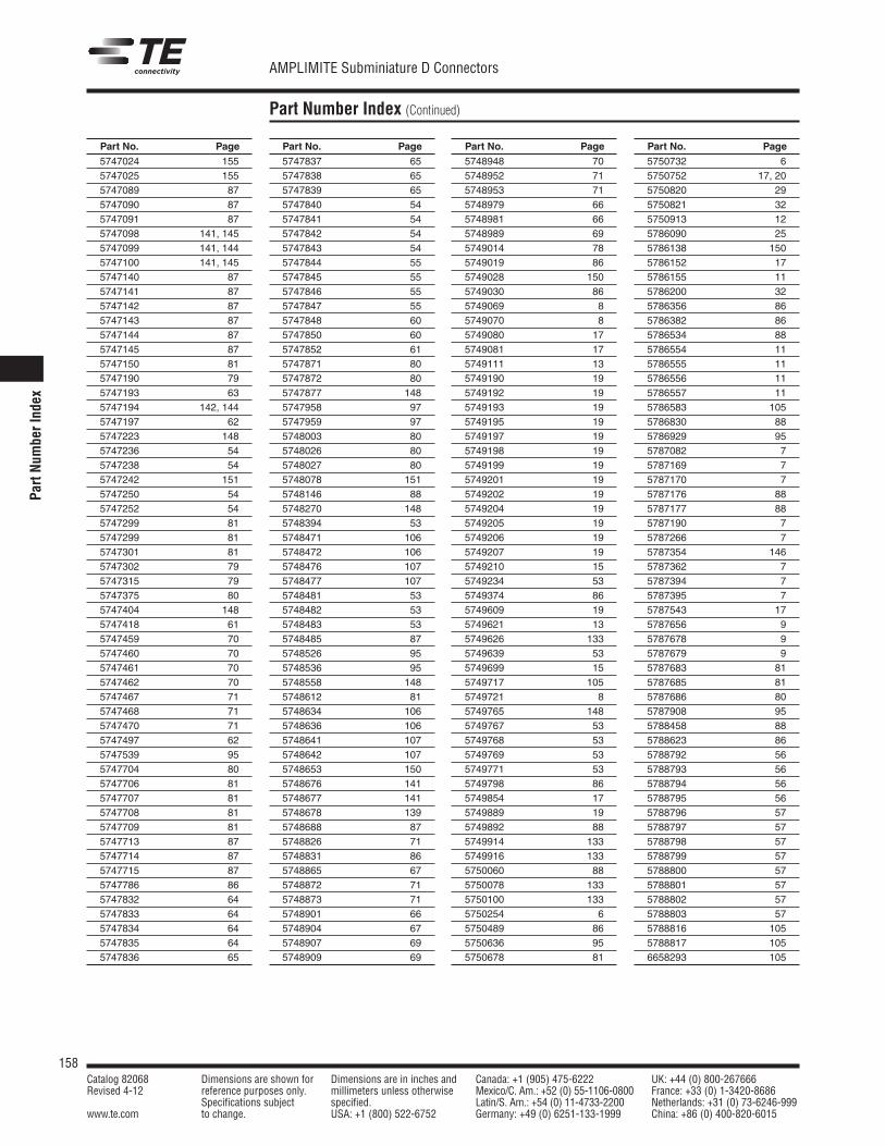
5747837 655747838 655747839 655747840 545747841 545747842 545747843 545747844 555747845 555747846 555747847 555747848 605747850 605747852 615747871 805747872 805747877 1485747958 975747959 975748003 805748026 805748027 805748078 1515748146 885748270 1485748394 535748471 1065748472 1065748476 1075748477 1075748481 535748482 535748483 535748485 875748526 955748536 955748558 1485748612 815748634 1065748636 1065748641 1075748642 1075748653 1505748676 1415748677 1415748678 1395748688 875748826 715748831 865748865 675748872 715748873 715748901 665748904 675748907 695748909 69
Part No. Page5747024 1555747025 1555747089 875747090 875747091 875747098 141, 1455747099 141, 1445747100 141, 1455747140 875747141 875747142 875747143 875747144 875747145 875747150 815747190 795747193 635747194 142, 1445747197 625747223 1485747236 545747238 545747242 1515747250 545747252 545747299 815747299 815747301 815747302 795747315 795747375 805747404 1485747418 615747459 705747460 705747461 705747462 705747467 715747468 715747470 715747497 625747539 955747704 805747706 815747707 815747708 815747709 815747713 875747714 875747715 875747786 865747832 645747833 645747834 645747835 645747836 65
Part No. Page5748948 705748952 715748953 715748979 665748981 665748989 695749014 785749019 865749028 1505749030 865749069 85749070 85749080 175749081 175749111 135749190 195749192 195749193 195749195 195749197 195749198 195749199 195749201 195749202 195749204 195749205 195749206 195749207 195749210 155749234 535749374 865749609 195749621 135749626 1335749639 535749699 155749717 1055749721 85749765 1485749767 535749768 535749769 535749771 535749798 865749854 175749889 195749892 885749914 1335749916 1335750060 885750078 1335750100 1335750254 65750489 865750636 955750678 81
Part No. Page5750732 65750752 17, 205750820 295750821 325750913 125786090 255786138 1505786152 175786155 115786200 325786356 865786382 865786534 885786554 115786555 115786556 115786557 115786583 1055786830 885786929 955787082 75787169 75787170 75787176 885787177 885787190 75787266 75787354 1465787362 75787394 75787395 75787543 175787656 95787678 95787679 95787683 815787685 815787686 805787908 955788458 885788623 865788792 565788793 565788794 565788795 565788796 575788797 575788798 575788799 575788800 575788801 575788802 575788803 575788816 1055788817 1056658293 105
Part No. Page
158Catalog 82068 Dimensions are shown for Dimensions are in inches and Canada: +1 (905) 475-6222 UK: +44 (0) 800-267666Revised 4-12 reference purposes only. millimeters unless otherwise Mexico/C. Am.: +52 (0) 55-1106-0800 France: +33 (0) 1-3420-8686
Specifications subject specified. Latin/S. Am.: +54 (0) 11-4733-2200 Netherlands: +31 (0) 73-6246-999www.te.com to change. USA: +1 (800) 522-6752 Germany: +49 (0) 6251-133-1999 China: +86 (0) 400-820-6015
Part Number Index (Continued)
AMPLIMITE Subminiature D Connectors
Part
Num
berI
ndex
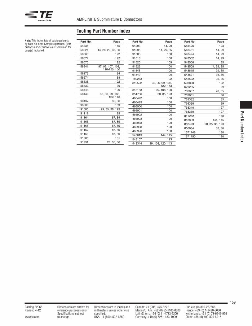
54334 14558024 14, 28, 29, 35, 3658063 12258074 12258075 12258241 97, 99, 107, 108,
118-120, 13058273 8858274 8858338 12258430 3658448 10058449 35, 36, 99, 108,
120, 14390437 35, 3690800 10991085 29, 35, 36, 12391112 2991164 87, 8991165 87, 8991166 87, 8991167 87, 8991168 87, 8991285 10191291 28, 35, 36
Part No. Page91293 14, 2991295 14, 29, 3591503 10091513 10091520 10991525 10091548 10091549 100189263 102312522 35, 36, 99, 108,
120, 143313183 99, 108, 120354786 28, 35, 123466422 100466423 100466900 100466901 100466902 100466903 100466963 100466968 100466996 100543013 144, 145543157 123543344 99, 108, 120, 143
Part No. Page543426 123543481 14, 29543494 14, 29543502 14, 29543506 35543508 14, 29, 35543515 29, 35543521 35, 36543522 35, 36608868 122679235 29762637 28, 35762661 36763382 35768338 29768340 127768350 127811262 148813809 144, 145852423 28, 35, 36, 123856684 35, 361571749 1301571750 130
Part No. Page
159Catalog 82068 Dimensions are shown for Dimensions are in inches and Canada: +1 (905) 475-6222 UK: +44 (0) 800-267666Revised 4-12 reference purposes only. millimeters unless otherwise Mexico/C. Am.: +52 (0) 55-1106-0800 France: +33 (0) 1-3420-8686
Specifications subject specified. Latin/S. Am.: +54 (0) 11-4733-2200 Netherlands: +31 (0) 73-6246-999www.te.com to change. USA: +1 (800) 522-6752 Germany: +49 (0) 6251-133-1999 China: +86 (0) 400-820-6015
Note: This index lists all cataloged partsby base no. only. Complete part nos. (withprefixes and/or suffixes) are shown on thepage(s) indicated.
Tooling Part Number Index
AMPLIMITE Subminiature D Connectors
PartNum
berIndex

AMPLIMITESubminiature D Connectors
TEConnectivity
Catalog82068
Revise
d4-12
te.com
© 2012 Tyco Electronics Corporation, a TE Connectivity Ltd. Company. All Rights Reserved.
82068 LUG PDF 04/2012
TE Connectivity and the TE connectivity (logo) are trademarks. Other logos, product and/or company
names might be trademarks of their respective owners.
AMPLIMITESubminiatureDConnectors


![TE Cover+Spine Master · .000030[0.00076] .000030[0.00076] .000030[0.00076] gold—500cycles gold—500cycles gold—500cycles Durability GoldFlash— GoldFlash— GoldFlash— 100cycles](https://img.pdfslide.us/doc/110x75/5f6382c9732115248b533a08/te-coverspine-master-000030000076-000030000076-000030000076-golda500cycles.jpg)


![TE Cover+Spine MasterShell—Steel, zinc or tin plated Insert—94V-0 rated thermoplastic, black Mounting Holes: St an dr — .12 0[3 5]Di Cl inc hNu t— 4- 0 readsw self-locking](https://img.pdfslide.us/doc/110x75/6009804c50cc8362c84e57ce/te-coverspine-master-shellasteel-zinc-or-tin-plated-inserta94v-0-rated-thermoplastic.jpg)