Embed Size (px)
Citation preview

OPERATING AND SAFETY INSTRUCTIONS FOR AIR DRIVEN TOUGHLIFT UNITS
TDS:-
1447 Prepared by:- Malcolm Macfie Approved by:- Martin Davies Date:15/01/17
REV NO:- 01 02
ECO:- 4850 4923
Page 1 of 11
1. SCOPE
The TOUGHLIFT Jacking system is designed to be operator friendly when being used. However, SAFETY COMES FIRST and the operator must be familiar with the potential dangers of not using the jack correctly. Hi-Force TOUGHLIFT compressed air driven jacking systems are designed to operate a high pressure hydraulic double acting cylinder with an operating pressure of 700Bar (10,000 psi). These instructions cover the following Toughlift models:
TLA10016, TLA10021, TLA15015, TLA15020, TLA20015 & TLA20027 - 7 bar (maximum) air supply. Refer to name plate on the pump for identification. 2. INSPECTION OF THE PRODUCT UPON RECEIPT On receipt of the product, visually inspect the item for any evidence of shipping damage. Please note shipping damage is not covered by warranty. If shipping damage is found, notify the carrier immediately and refrain from putting the product into service. The carrier is responsible for the repair and replacement costs from damage in transit shipment. 3. SAFETY ISSUES
IMPORTANT NOTE: It is the responsibility of the purchaser to ensure that operators of this equipment are properly trained, wear proper protective gear in its safe use and have access to Hi-Force Operating and Safety Instructions.
No modification and/or additions may be made to the equipment without the written permission of the manufacturer. Keep these instructions and other applicable Hi-Force manuals during the life of the equipment and make sure they are available for all personnel that install, use and maintain the equipment.
READ ALL OF THIS MANUAL BEFORE OPERATING THE JACKING SYSTEM
FAILURE TO OBSERVE THE FOLLOWING WARNINGS COULD RESULT IN SERIOUS BODILY INJURY
● Read and follow all the instructions and safety warnings carefully prior to use of the
equipment. Failure to do so could result in equipment damage or failure of the equipment or personal injury. Hi-Force will not be held responsible for any damage to the equipment or personal injury resulting from unsafe use of the product, lack of maintenance or incorrect operation. If in doubt on the correct usage of any Hi-Force equipment, contact your nearest Hi-Force office or distributor. If the operator has not been trained on high pressure hydraulic equipment and its safe use, consult your local Hi-Force sales office who can offer you training courses for operators.
● All operators should ensure that all necessary personal protective equipment as specified by their employer is worn when operating any hydraulic equipment. Safety shoes, safety glasses/visor and protective gloves should be worn at all time. All relevant risk assessments should be completed prior to use of the equipment.
● Jack must only be used on flat level stable surfaces capable of holding the load being lifted. Where stable surface is not available, a suitable load bearing plate capable of distributing the load must be placed between the ground and the jack base plate when performing the lift. DO NOT LIFT in soft or unstable ground alone.
● Use a jack with sufficient capacity to lift the load required.

OPERATING AND SAFETY INSTRUCTIONS FOR AIR DRIVEN TOUGHLIFT UNITS
TDS:-
1447 Prepared by:- Malcolm Macfie Approved by:- Martin Davies Date:15/01/17
REV NO:- 01 02
ECO:- 4850 4923
Page 2 of 11
● Never support a load solely by hydraulic means, the jack is to be used for LIFTING applications only.
● Mechanical support must always be used before working on, under or near a lifted load.
● Use friction material under the base and between the jack and load. ● Lift only dead weight loads. ● Keep unauthorised personnel clear of lifted loads. ● Use only approved hydraulic oil for the Toughlift unit. ● Supply pump must have sufficient oil to fully stroke the jack. Check oil level regularly
and replenish as required. ● Do not use jacks if damaged, altered or in poor repair. ● User must ensure that all safety labels are maintained and replaced as lack of
readability becomes evident. ● Disconnect the Toughlift from the air source when carrying out maintenance or
adjustments.
4. SPECIFICATIONS The Toughlift jacking system uses a three speed pump with the following pressure and flow ranges
Pressure range (bar) Flow (l/min)
0-65 7.0
65-325 1.6
325-700 0.75
Useable oil capacity in the tank 12 litres
Max sound pressure level 90 dB(A)
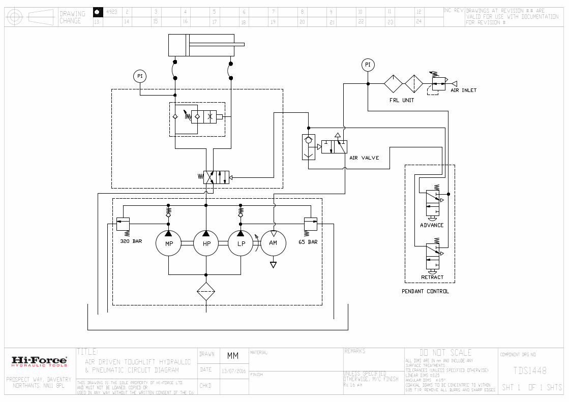
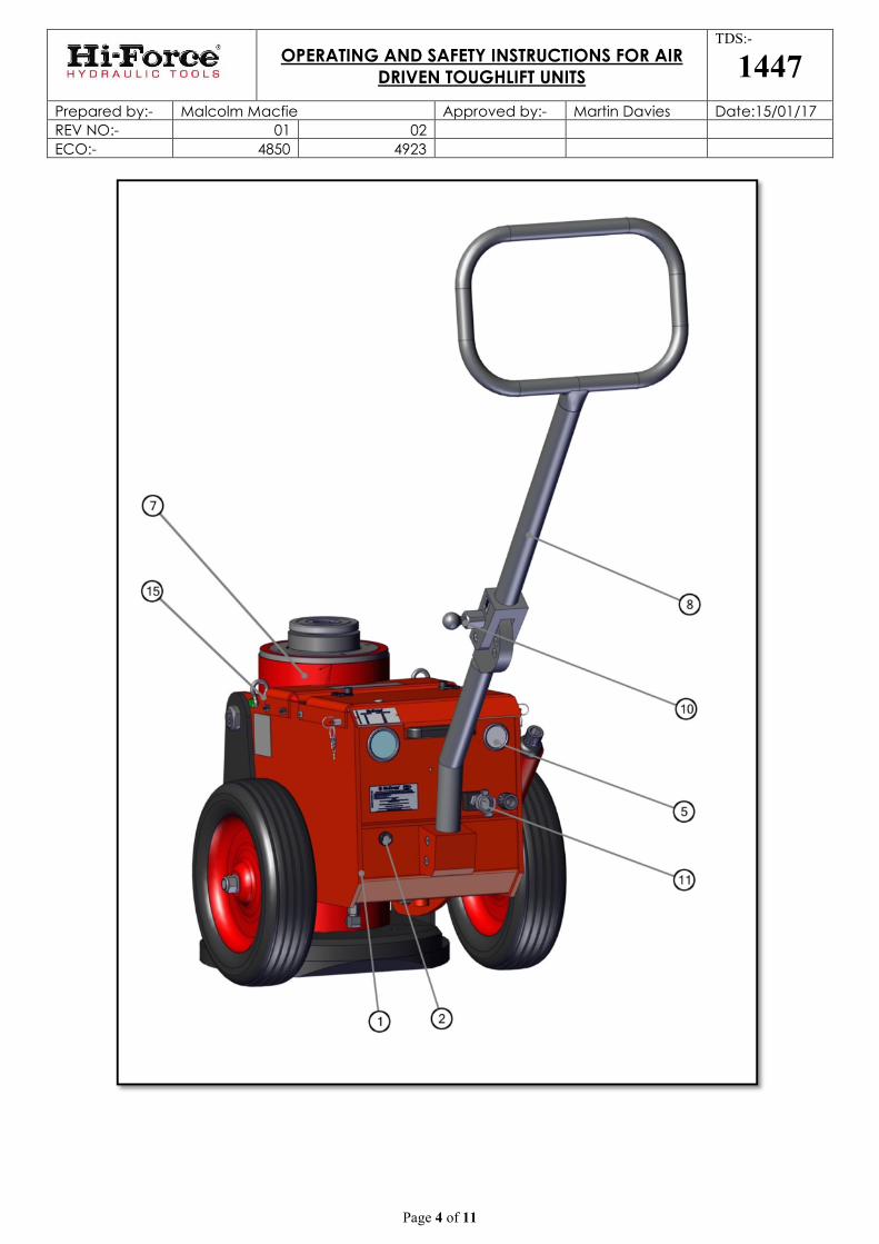
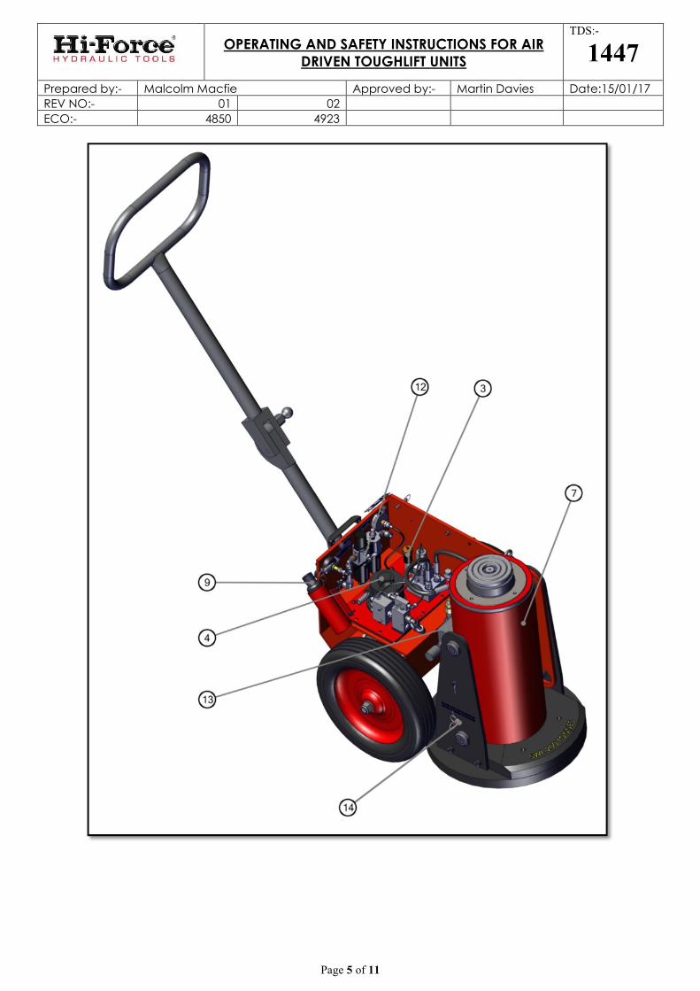
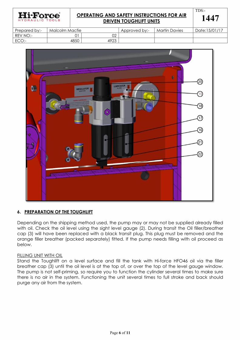
5. IDENTIFICATION OF COMPONENTS
Refer to diagrams on pages 3, 4, 5 & 6.
1. Oil Reservoir 2. Oil level gauge
3. Oil filler/ breather cap 4. Air Motor
5. Air supply pressure gauge 6. Tonnage load gauge
7. Cylinder 8. Handle
9. Control pendant 10. Handle release
11. Air supply connection 12. Air filter/regulator/lubricator unit
13. Load lowering valve 14. Transit pins
15. Lifting shackles 16. Air lubricant reservoir
17. Water trap 18. Air lubricator filler plug
19. Air lubricator control 20. Air pressure regulator
21. Drain button 22. Drain port

OPERATING AND SAFETY INSTRUCTIONS FOR AIR DRIVEN TOUGHLIFT UNITS
TDS:-
1447 Prepared by:- Malcolm Macfie Approved by:- Martin Davies Date:15/01/17
REV NO:- 01 02
ECO:- 4850 4923
Page 3 of 11
OPERATING AND SAFETY INSTRUCTIONS FOR AIR DRIVEN TOUGHLIFT UNITS
TDS:-
1447 Prepared by:- Malcolm Macfie Approved by:- Martin Davies Date:15/01/17
REV NO:- 01 02
ECO:- 4850 4923
Page 4 of 11
OPERATING AND SAFETY INSTRUCTIONS FOR AIR DRIVEN TOUGHLIFT UNITS
TDS:-
1447 Prepared by:- Malcolm Macfie Approved by:- Martin Davies Date:15/01/17
REV NO:- 01 02
ECO:- 4850 4923
Page 5 of 11
OPERATING AND SAFETY INSTRUCTIONS FOR AIR DRIVEN TOUGHLIFT UNITS
TDS:-
1447 Prepared by:- Malcolm Macfie Approved by:- Martin Davies Date:15/01/17
REV NO:- 01 02
ECO:- 4850 4923
Page 6 of 11
6. PREPARATION OF THE TOUGHLIFT Depending on the shipping method used, the pump may or may not be supplied already filled with oil. Check the oil level using the sight level gauge (2). During transit the Oil filler/breather cap (3) will have been replaced with a black transit plug. This plug must be removed and the orange filler breather (packed separately) fitted. If the pump needs filling with oil proceed as below. FILLING UNIT WITH OIL Stand the Toughlift on a level surface and fill the tank with Hi-force HFO46 oil via the filler breather cap (3) until the oil level is at the top of, or over the top of the level gauge window. The pump is not self-priming, so require you to function the cylinder several times to make sure there is no air in the system. Functioning the unit several times to full stroke and back should purge any air from the system.

OPERATING AND SAFETY INSTRUCTIONS FOR AIR DRIVEN TOUGHLIFT UNITS
TDS:-
1447 Prepared by:- Malcolm Macfie Approved by:- Martin Davies Date:15/01/17
REV NO:- 01 02
ECO:- 4850 4923
Page 7 of 11
FILL AIR SUPPLY LUBRICANT RESERVOIR. Remove air lubricant filler plug (18) and fill air lubricant reservoir (16) with ISO VG 32 turbine oil to the fill line marked on the reservoir. CONNECT AIR SUPPLY Check that the air supply is via a minimum hose size of at least ½” (13mm) bore, that the available pressure is at least 5.5 bar (80psi) and preferably 7 bar (100psi) and that the compressor can supply a minimum flow of 50 cfm (25 l/sec). The pump will run satisfactorily below these figures but piston travel rate will be affected and therefore the rate at which the cylinder will advance will reduce. Install a suitable connector for the hose system in use into the air inlet (11). The connection on the inlet is a standard universal claw fitting. MOVING AND TRANSPORTING THE JACK
1. Adjust the handle to the most comfortable position by pulling the handle release (10) and swinging the handle round until it locks into the appropriate handle latch pin hole on the side of the lower handle body.
2. Tilt the jack right back onto its wheels, allowing it to be manoeuvred into the approximate location.
3. Position the Jack accurately under the lifting position by adjusting the handle to the lowest position and tilting the jack back slightly onto its wheels. This allows the jack to be moved whilst ‘V LIFT’ SYSTEM keeps the cylinder vertical. PLEASE ensure that when the handle is allowed to raise back up, your hands are CLEAR OF ANY SURFACE ABOVE, as this could cause your hands to be trapped between the unit and the vehicle. Ensure the saddle is centrally under the lift area before the lift commences.
4. If you are lifting the Toughlift onto a maintenance truck or trailer, only use the lifting eyes provided on the unit (15). Before lifting, fold the handle forward over the top of the cylinder and pass the lifting strap through the centre of the handle loop. Use only a lifting strap with a minimum capacity of 1Tonne with appropriately rated shackles on either end.
5. Before lifting the unit, make sure the transit pins (14) are replaced by lifting the handle up, pushing the red button in on the pins and pushing them through till they locate. Once this has been done the Toughlift can be safely lifted.
7. OPERATION
WARNING: ALWAYS ENSURE JACK IS POSITIONED AND LIFTS VERTICALLY! TO OPERATE THE JACK
1. Make sure the transit pins (14) have been removed before the unit is operated. This is done by lifting the handle up to take the weight off the pins, then depressing the red buttons on each of the pins, slide them both out.
2. Connect to the air supply using appropriate universal claw fitting, making sure a safety clip is used.
3. Switch the air on. (Pressure to the unit should ideally be between 6.2 bar (90 psi) and 7.0 bar (100 psi). Check the operating pressure is not set too high or low and adjust

OPERATING AND SAFETY INSTRUCTIONS FOR AIR DRIVEN TOUGHLIFT UNITS
TDS:-
1447 Prepared by:- Malcolm Macfie Approved by:- Martin Davies Date:15/01/17
REV NO:- 01 02
ECO:- 4850 4923
Page 8 of 11
with the pressure regulating valve located at the rear of the jack adjacent to the air pressure gauge.
4. Using the air remote pendant, press the UP arrow button to extend the jacking cylinder and DOWN arrow button to retract the cylinder.
5. Advance the lifting rod to lift the load checking constantly that the load is stable and the jack remains in a fixed and vertical, stable, position.
6. Check the Tonnage load gauge (6) using the conversion label on the lid edge above the gauge. This should confirm what load is being applied by the jack. There is also a copy of the conversion tables for each Toughlift model in Appendix A at the back of this document.
7. Fit load blocks as required and lower load onto blocks if used.
8. ADDITIONAL OPERATION HINTS. AIR LUBRICANT Adjust the air lubricant control (19) such that one drop of oil is being added to the air approximately every minute. The lubricant drops can be seen through the lubricant control knob on the top of the unit. Allowing more oil into the motor than this can cause contamination of the exhaust flow. 9. MAINTENANCE Carrying out the following on a regular basis is recommended to keep the jacking system operating in a trouble free manner. The time between maintenance is determined by the frequency of use and the site conditions. Keep the unit clean, particularly the saddle, locking and extension pieces (if used). All saddle receiver holes should be blown out with compressed air, then lightly lubricate the pins and saddle receiver holes. Lubricate handle latch pin and holes. The oil level in the reservoir should not be allowed to fall below the top of the oil level indicator. To check oil level with the cylinder in the fully retracted position is essential so that the correct oil level is displayed. Keep the reservoir topped up with Hi-Force HFO46 oil via the filler breather cap (3). If the oil level does fall below the oil level indicator then air could be drawn into the pump causing erratic operation and possible damage. To top up hydraulic oil remove the top cover and fill via orange filler cap. Oil should be replaced after approximately 500 working hours, or more frequently in dusty conditions. To replace the oil, disconnect from air supply, remove the plug on the tank base and drain used oil out into a suitable container. Dispose of oil in a responsible manner. Refill with Hi-Force HFO46 oil. Check air system lubricator oil level (16). Maintain level close to the maximum mark shown and use only Turbine oil ISO-VG32. Adjust number of oil drops to 1-2 during lift cycle. Air lubricating oil should be topped up as required via the air lubricant filler plug. DO NOT use hydraulic oil. Pressure gauges should be calibrated at least every 12 months.
OPERATING AND SAFETY INSTRUCTIONS FOR AIR DRIVEN TOUGHLIFT UNITS
TDS:-
1447 Prepared by:- Malcolm Macfie Approved by:- Martin Davies Date:15/01/17
REV NO:- 01 02
ECO:- 4850 4923
Page 9 of 11
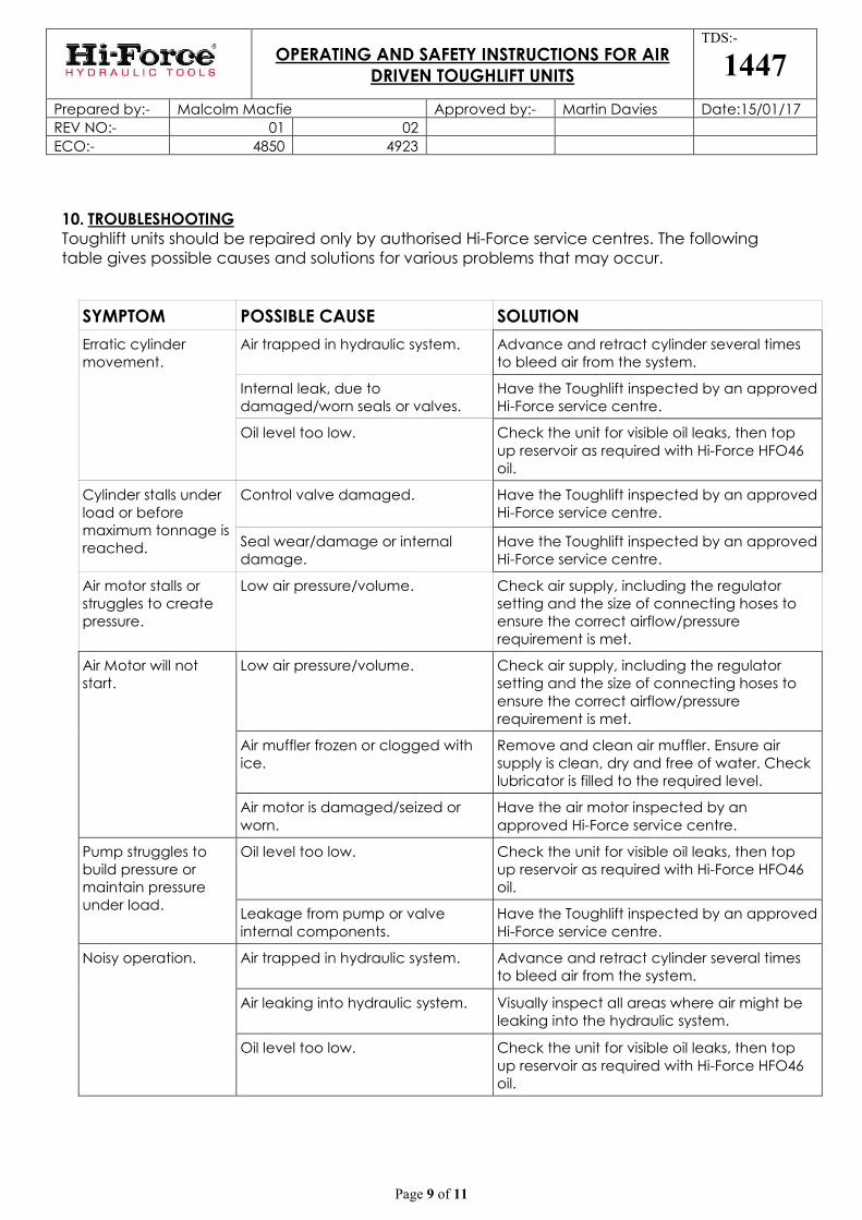
10. TROUBLESHOOTING Toughlift units should be repaired only by authorised Hi-Force service centres. The following table gives possible causes and solutions for various problems that may occur.
SYMPTOM POSSIBLE CAUSE SOLUTION
Erratic cylinder movement.
Air trapped in hydraulic system. Advance and retract cylinder several times to bleed air from the system.
Internal leak, due to damaged/worn seals or valves.
Have the Toughlift inspected by an approved Hi-Force service centre.
Oil level too low. Check the unit for visible oil leaks, then top up reservoir as required with Hi-Force HFO46 oil.
Cylinder stalls under load or before maximum tonnage is reached.
Control valve damaged. Have the Toughlift inspected by an approved Hi-Force service centre.
Seal wear/damage or internal damage.
Have the Toughlift inspected by an approved Hi-Force service centre.
Air motor stalls or struggles to create pressure.
Low air pressure/volume. Check air supply, including the regulator setting and the size of connecting hoses to ensure the correct airflow/pressure requirement is met.
Air Motor will not start.
Low air pressure/volume. Check air supply, including the regulator setting and the size of connecting hoses to ensure the correct airflow/pressure requirement is met.
Air muffler frozen or clogged with ice.
Remove and clean air muffler. Ensure air supply is clean, dry and free of water. Check lubricator is filled to the required level.
Air motor is damaged/seized or worn.
Have the air motor inspected by an approved Hi-Force service centre.
Pump struggles to build pressure or maintain pressure under load.
Oil level too low. Check the unit for visible oil leaks, then top up reservoir as required with Hi-Force HFO46 oil.
Leakage from pump or valve internal components.
Have the Toughlift inspected by an approved Hi-Force service centre.
Noisy operation. Air trapped in hydraulic system. Advance and retract cylinder several times to bleed air from the system.
Air leaking into hydraulic system. Visually inspect all areas where air might be leaking into the hydraulic system.
Oil level too low. Check the unit for visible oil leaks, then top up reservoir as required with Hi-Force HFO46 oil.

OPERATING AND SAFETY INSTRUCTIONS FOR AIR DRIVEN TOUGHLIFT UNITS
TDS:-
1447 Prepared by:- Malcolm Macfie Approved by:- Martin Davies Date:15/01/17
REV NO:- 01 02
ECO:- 4850 4923
Page 10 of 11
Appendix A
200T CONVERSION TABLE
PRESSURE (bar) TONNAGE (Tonnes)
100 28.6
200 57.1
300 85.7
400 114.3
500 142.9
600 171.4
700 200
150T CONVERSION TABLE
PRESSURE (bar) TONNAGE (Tonnes)
100 21.4
200 42.8
300 64.3
400 85.7
500 107.1
600 128.6
700 150
100T CONVERSION TABLE
PRESSURE (bar) TONNAGE (Tonnes)
100 14.3
200 28.6
300 42.8
400 57.1
500 71.4
600 85.7
700 100
OPERATING AND SAFETY INSTRUCTIONS FOR AIR DRIVEN TOUGHLIFT UNITS
TDS:-
1447 Prepared by:- Malcolm Macfie Approved by:- Martin Davies Date:15/01/17
REV NO:- 01 02
ECO:- 4850 4923
Page 11 of 11
UK Head Office:
Hi-Force Limited Prospect Way, Daventry, Northamptonshire
NN11 8PL United Kingdom
Tel: + 44 1327 301000 Fax: + 44 1327 706555
Email: [email protected]
Hi-Force Regional Offices:
Hi-Force Caspian Baku
Azerbaijan Tel: +994 12 447 4100
Email: [email protected]
Hi-Force S.r.l. Milan Italy
Tel: +39 0253 031 088 Email: [email protected]
Hi-Force Hydraulics (Asia) S.B
Selangor Malaysia
Tel: +603 5525 4203 Email: [email protected]
Hi-Force Nederland BV
Strijen Netherlands
Tel: +31 78 674 5488 Email: [email protected]
Hi-Force Hydraulics (Pty) Ltd
Midrand South Africa
Tel: +27 11 314 0555 Email: [email protected]
Hi-Force Aberdeen
Aberdeen United Kingdom
Tel: +44 1224 973 512 Email: [email protected]
Hi-Force Hydraulics
Abu Dhabi United Arab Emirates Tel: +971 2 551 3100
Email: [email protected]
Hi-Force FZCO
Dubai United Arab Emirates Tel: +971 4 815 0600
Email: [email protected]
GLOBAL BRAND. LOCAL SERVICE. www.hi-force.com