Embed Size (px)
Citation preview
tdata ___ _ Volume 1 Issue #8 ©
WHAT THE MACHINE IS THINKING "I know what you're thinking about," said Tweedle-
dum; "but it isn't so, nohow. " ,., - .. . "continued Tweedledee, "if it was so, It mzght be; and if it were so, it would be; but as it isn't, it ain't. That's logic."
-ALICE IN WONDERLAND W ILD electrons tamed and commanded to through and_ perform all manner
. _of tncks. Fun JUSt to thmk about the goings on w1thm the COSMAC microprocessor. What mad p_ursuit? What struggle to escape? What pipes and timbrels? What wild electron ecstasy? What para-
of Keats? Electrons herded about through logic gates and corralled into little pens (registers) and
little boxes with addresses on them (memory). Wmng that can configure and reconfigure. Micro-
processors have to be one of mankind's and technol-ogy's finest wonders.
Knowledge about our little computers does not come all at once. Programming creeps up on you until something inside your head clicks and you say aha! If things have not clicked together for you yet, they will· it is a matter of reading everything about micro: computers in sight, talking to other hobbyists, reading COSMAC code listing, and experimenting a lot.
Machine and assembly lan-guage are rewarding and are the only languages where you will feel the full power of the computer. If you learn a language like BASIC, you will always feel that there is this "some-thing" you don't know. Indeed, the language of BASIC itself is written with a lot of creative machine code. Machine language will always take up the least amount of memory. If you know machine code, you are among the elite of the microcomputer hobbyists.
Today we are going to discover how a language like BASIC knows how to recognize words like LET. Before we proceed, let's review the AND and OR in-structions, and add two new ones XRI and SHIFT:
• The AND instruction can turn a bit or bits to zero wi.thout affecting the other bits in a byte. It can test an individual bit or turn many bits to zero. This is done by con-structing a MASK (programmer word for· the immediate byte), the D's in the MASK will block out (turn to 0) the byte in the D(starting) register:
• The inclusive OR instruction will add a bit or bits to a byte without touching any of
<tfi!Om Qe6t to /light: J\:Qi.Ce, g weedQedee and g weedQedum Oil iS tt lii.Ce liPlrro?
the other bits in the byte. The MASK in the immediate byte consists of 1 's which turn the bit positions in which they are entered into 1 's. A 0 in the OR MASK will not affect the bit or bits in the same bit position in the D(s) byte.
• The eXclusive OR instruction can be used to turn a byte into its complement: 1100 0101 becomes 0011 1 010 when the XRI byte is FF ( 1111 1111 ). The XRI -instruction can also be used to compare logical and make decisions based upon the outcome. This is done by using as a MASK for the value you wish to test. If you want to test whether 4C has entered your programming net, then 4C or 0100 1100 is your MASK.
• SHIFT (Right, Left- with and without ring shifting) is able to bounce things off to oblivion (to the right is divide by 2 and to the left is multiply by 2). Or the bits can make a complete circle with a bit first being brought into the DF (data flag). By entering a 0 in the highest bit position and executing a SHLC, the DF is cleared to 0 and whatever was in the DF becomes the lowest bit position.
More details on these last two items and examples will be given on the next three pages.
CIJlr.llC Clll8 Clll8 Clll8 CDSr:v:tC Clll8 CDSr:lAC Clll8
In the last issue of QUESTDATA, recall that the logic instructions perform their operations upon the individual bits of a byte. In the case of an Inclusive OR (RCA just calls this a regular OR), we learned that if one or the other of the bits in the ORing operation is a one then the result is a one. The only time the result D(f) is a zero (0), is when the imme-diate (data mask) and the D(s) starting value are O's. The Inclusive OR is consistent with our semantic expectation of the word OR. When A OR B is true then C is true . If C represents "is a chess player" and C is true statement, then we know that either Andy or Bill or both are chess players.
The eXclusive OR (XRI in this case) puts a condi-tion upon the Inclusive OR. It says, " the BOTH ON (1 's) condition will cause a ZERO (0) in the final D(f) result." Repeating the "chess player" example with the eXclusive OR, we find: If we know that C (is a chess player is true) then we know Andy OR Bill, BUT NOT BOTH, is a chess player.
XRI LOGIC TABLE Immediate D(s) D(f)
0 0 0 0 1 1 0 1 1 0
This semantic handle on the logic situation of ORI (OR Immediate) and XRI (eXclusive Or Immediate) are to give you a hand in memorizing the logic tables of the bit values. The usefulness of the XRI instruction becomes apparent when you want to COMPARE and MATCH numeric or alphabetic values. It is the XRI concept which allows the computer to "know" and display the word "LET" in the language BASIC. Try to figure out what the result of XRiing A4 and 6D will be. First translate these two hex numbers into binary 1 's and O's using the handy and speedy table on page 3. Then translate these values back into hex once you have found the answer. Hopefully, your results match the COSMAC machines.
What would be the result of XRiing 0011 OliO and 1100 1100? What about 0011 0010 XRied with 0011 0010? Right, what you have found by putting these last two values into the laboratory experimenter is exactly the property which lets you discover when the number 2 in ASCII code has been " found." You got it, a match between two like binary codes will yield 0000 0000 and we have an easy way to test for this condition- good old BNZ (3A hex) and BZ (32 hex). Last lesson we touched upon the fact that
with FF will give the complement (or in other
QUESTDA T A COSMAC CLUB
Page 2
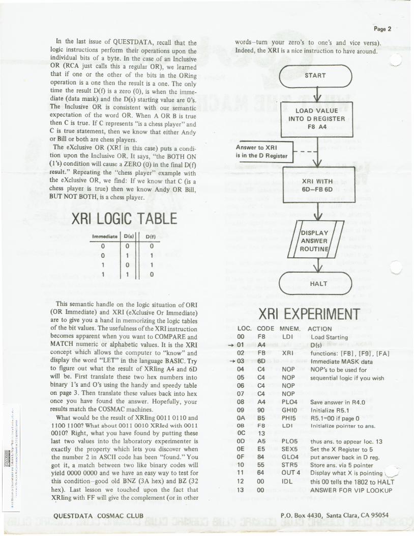
words-turn your zero's to one's and vice versa). Indeed, the XRI is a nice instruction to have around.
Answer to XRI
LOAD VALUE INTO D REGISTER ·
F8 A4
is in the D Register
XRI LOC. CODE 00 F8
-+ 01 A4 02 FB
-+ 03 60 04 C4 05 C4 06 C4 07 C4 08 A4 09 90 OA 85 OB F8 oc 13 00 A5 OE E5 OF 84 10 55 11 64 12 00 13 00
XRI WITH 60-FB 60
EXPERIMENT MNEM . ACTION LDI Load Starting
D(s) XRI functions: [FB], [F9), [FA)
Immediate MASK data NOP NOP's to be used for NOP sequential logic if you wish NOP NOP PL04 Save answer in R4.0 GHIO Initialize R5.1 PHI5 R5.1=00 if page 0 LDI Initialize pointer to ans.
PL05 thus ans. to appear loc. 13 SEX5 Set the X Register to 5 GL04 put answer back in D reg. STR5 Store ans. via 5 pointer OUT4 Display what X is IDL this 00 tells the 1802 to HALT
ANSWER FOR VIP LOOKUP
P.O. Box 4430, Santa Clara, CA 95054
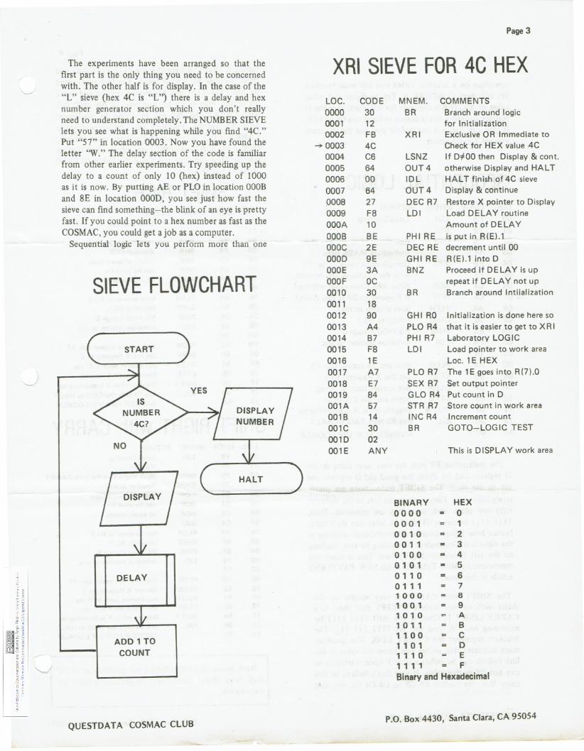
The experiments have been arranged so that the first part is the only thing you need to be concerned with. The other half is for display. In the case of the "L" sieve (hex 4C is "L") there is a delay and hex number generator section which you don't really need to understand completely. The NUMBER SIEVE lets you see what is happening while you find "4C." Put "57" in location 0003. Now you have found the letter "W." The delay section of the code is familiar from other earlier experiments. Try speeding up the delay to a count of only 10 (hex) instead of 1000 as it is now. By putting AE or PLO in location OOOB and 8E in location OOOD, you see just how fast the sieve can find something-the blink of an eye is pretty fast. If you could point to a hex number as fast as the COSMAC, you could get a job as a computer.
Sequential logic lets you perform more than one
SIEVE FLOWCHART
START
DELAY
ADD 1 TO COUNT
QUESTDATA COSMAC CLUB
DISPLAY
HALT
XRI LOC. 0000 0001 0002
--+ 0003 0004 0005 0006 0007 0008 0009 OOOA OOOB oooc OOOD OOOE bOOF 0010 0011 0012 0013 0014 0015 0016 0017 0018 0019 001A 0018 001C 0010 001 E
Page 3
SIEVE FOR 4C HEX CODE MNEM. COMMENTS
30 BR Branch around logic 12 for Initialization FB XRI Exclusive OR Immediate to 4C Check for HEX value 4C C6 LSNZ If D#OO then Display & cont. 64 OUT4 otherwise Display and HALT 00 IDL HALT finish of 4C sieve 64 OUT4 Display & continue 27 DEC R7 Restore X pointer to Display F8 LDI Load DELAY routine 10 Amount of DELAY BE PHIRE is put in R(E).1 2E DEC RE decrement until 00 9E GHIRE R(E).1 into D 3A BNZ Proceed if DELAY is up oc repeat if DELAY not up 30 BR Branch around lntiialization 18 90 GHI RO Initialization is done here so A4 PLO R4 that it is easier to get to X R I 87 PHI R7 Laboratory LOGIC F8 LDI Load pointer to work area 1E Loc. 1 E HEX A7 PLO R7 The 1E goes into R(7).0 E7 SEX R7 Set output pointer 84 GLO R4 Put count in D 57 STR R7 Store count in work area 14 INC R4 Increment count 30 BR GOTO-LOGIC TEST 02 ANY This is DISPLAY work area
BINARY HEX 00 0 0 0 0 0 01 1 0010 2 0011 3 0100 4 0101 5 0110 = 6 0 11 1 7 100 0 8 1001 9 101 0 A 1 0 1 1 B 11 0 0 c 1101 D 1 1 1 0 E 1 1 1 1 F Binary and Hexadecimal
P.O. Box 4430, Santa Clara, CA 95054
operation on a number. Often you will want to add a bit and then COMPARE it. Try to figure out what value of XRI (FB is the code for XRI) will turn the D register to zero when it comes to locations 06 and 07. If you can figure it out before you run the program
_
SEQUENTIAL LOGIC LOC. CODE MNEM. ACTION 00 F8 LDI Load Starting 01 32 D(s) 02 F9 ORI functions : [F9], [FB], [FA] 03 41 Immediate MASK data 04 FB XRI Complement value using FF 05 FF with the eXclusive OR lmmed. 06 C4 NOP What XRI Sieve value will turn
-+ 07 C4 NOP D Register to 00 at this point? 08 A4 PL04 Save answer in R4.0 09 90 GHIO Initialize R5.1 OA 85 PH15 R5.1=00 if page 0 OB F8 LDI Initialize pointer to ans. oc 13 OD A5 PL05 thus ans. to appear loc. 13 OE E5 SEX5 Set the X Register to 5 OF 84 GL04 put answer back in D reg. 10 55 STR5 Store ans. via 5 pointer 11 64 OUT4 Display what X is pointing to 12 00 IDL this 00 tells 1802 to HALT 13 00 ANSWER FOR VIP LOOKUP - ---- - -- ---
The instruction F8 puts the very next thing in the D register and F6 shifts the good old D register one bit to the right. The SHIFT instructions are pretty straightforward. They bounce the bits to the right (or left) one place each time they are executed. Thus, 1111 1111 becomes 0111 1111 after one shift right. Notice how things bounce off to oblivion-shifting to the right is the equivalent of dividing by two. Shifting to the left is multiplying by two. This is used and mentioned by Mike Tyborski in his NEW PATTERNS article in this issue.
The SHIFT with CARRY is very similar to the shifts without this' feature EXCEPT that there is a CARRY LINK [ ] . Thus, if you shift 1111 1111 by executing one 76, you will get ? 111 Ill [I] . The brackets represent the CARRY LINK. The question mark indicates that unless you know the value of the link (which can be either a 0 or I upon startup) you can not fill in this value. If you don't believe in this carry link, try loading F8 00 76 C4 C4 C4, etc. an:d
QUESTDATA COSMAC CLUB
Page 4
runing it after you have run the 11111111 shift you tried. Surprise 80 is your result The link was loaded by the 1111 1111 and has circled around and come up in the high order bit position. In the Shift left with CARRY this bit will be found in the lowest order bit position. You have also discovered that the CARRY LINK is not cleared to zero upon startup! Only I, N, X, P, Q, and R(O) are initialized to zero on startup. How can you make sure the link is 0? F8 00 76, out to do it.
SHIFT RIGHT LOC. CODE MNEM. ACTION 00 FS LDI Load Starting
-+ 01 OF VALUE 02 F6 SHR Shift Right One Bit 03 F6 SHR Another SHR 04 C4 NOP NOP's so same logic 05 C4 NOP can be used for 06 C4 NOP all experiments 07 C4 NOP 08 A4 PL04 Save answer in R4.0 09 90 GHIO Initialize R5.1 OA B5 PHIS R5.1=00 if page 0 OB FS LDI Initialize pointer to ans. oc 13 OD AS PL05 thus ans. to appear loc. 13 OE E5 SEX5 Set the X Register to 5 OF 84 GL04 put answer back in D reg. 10 55 STR5 Store ans. via 5 pointer 11 64 OUT4 Display what X is pointing to '-----" 12 00 IDL this 00 tells the 1802 to HALT 13 00 ANSWER FOR VIP LOOKUP
SHIFT RIGHT with CARRY LOC. CODE MNEM. ACTION 00 FS LDI Load Starting
--+ 01 OF VALUE 02 76 SHRC Shift Right One Bit with CARRY 03 76 SHRC Another SHRC 04 C4 NOP NOP's so same logic 05 C4 NOP can be used for 06 C4 NOP all experiments 07 C4 NOP 08 A4 PL04 Save answer in R4.0 09 90 GHIO Initialize R5.1 OA B5 PHIS R5.1=00 if page 0 OB FS LDI Initialize pointer to ans. oc 13 OD AS PL05 thus ans. to appear loc. 13 OE E5 SEX5 Set the X Register to 5 OF 84 GL04 put answer back in D reg. 10 55 STR5 Store ans. via 5 pointer 11 64 OUT4 Display what X is pointing to 12 00 IDL this 00 tells the 1802 to HALT 13 00 ANSWER FOR VIP LOOKUP
Back issues of QUESTDATA are available at $1.50 each from Quest Electronics. Programming skills are cumulative .
P.O. Box 4430, Santa Clara, CA 95054
MULTIPLE PRECISION Page 5
MULTIPLICATION By Ivan Dzombak
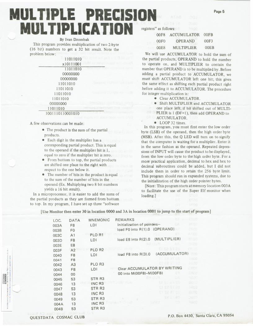
This program provides multiplication of two 2-byte (16 bit) numbers to get a 32 bit result. Note the problem below:
11011010 x10111001
11011010 00000000
00000000 11011010
11011010 11011010
11011010 00000000
11011010 1001110110001010
A few observations can be made:
• The product is the sum of the partial products.
• Each digit in the multiplier has a corresponding partial product. This is equal to the operand if the multiplier bit is 1, equal to zero if the multiplier bit is zero.
• From bottom to top, the partial products are shifted one place to the right with respect to the one below it.
• The number of bits in the product is equal to the sum of the number of bits in the operand (Ex. Multiplying two 8 bit numbers yields a 16 bit result).
In a microprocessor, it is easier to add the sums of the partial products as they are formed from bottom to top . In my program, I have set up three "software
registers" as follows: OOF8 ACCUMULATOR OOFB OOFO
OOE8
OPERAND
MULTIPLIER
OOF3
OOEB
We will use ACCUMULATOR to hold the sum of the partial products, OPERAND to hold the number to operate on, and MULTIPLIER to contain the number that OPERAND is to be multiplied by. Before adding a partial product to ACCUMULATOR, we must shift ACCUMULATOR left one bit; this gives the same effect as shifting each partial product right before adding it to ACCUMULATOR. The procedure for integer multiplication is:
• Clear ACCUMULATOR. • Shift MULTIPLIER and ACCUMULATOR
one place left ; if bit shifted out of MULTI-PLIER is 1 (DF=1), then add OPERAND to ACCUMULATOR.
• LOOP 32 times. In this program, you must first enter the low order
byte (LSB) of the operand, then the high order byte (MSB). After this, the Q LED will tum on to signify that the computer is waiting for a multiplier. Enter it in the same fashion as the operand. Repeated depres-sions of INPUT will cause the product to be displayed, from the low order byte to the high order byte. For a more practical application, decimal to hex and hex to decimal subroutines could be added, but I did not include them in order to retain the 256 byte limit. This program should run in expanded systems, due to the initialization of the high order pointer bytes.
[Nore: This program starts at memory location 003A to facilitate the use of the Super Elf monitor when loading.]
[Use Monitor then enter 30 in location 0000 and 3A in location 0001 to jump to the start of program]
LOG. DATA MNEMONIC REMARKS 003A FB LDI Initialization of pointers-0038 FO load FO into R(1 ).0 (OPERAND) 003C A1 PLO R1 003D FB LDI load EB into R(2).0 (MULTIPLIER)
003E EB 003F A2 PLO R2
(ACCUMULATOR) 0040 FB LDI load FB into R(3).0 0041 FB 0042 A3 PLO R3 0043 FB LDI Clear ACCUMULATOR BY WRITING 0044 00 00 into M(OOF8)-M(OOF8) 0045 53 STR R3 0046 13 INC R3 0047 53 STR R3 0048 13 INC R3 0049 53 STR R3 004A 13 INC R3 0048 53 STR R3
QUESTDATA COSMAC CLUB P.O. Box 4430, Santa Clara, CA 95054
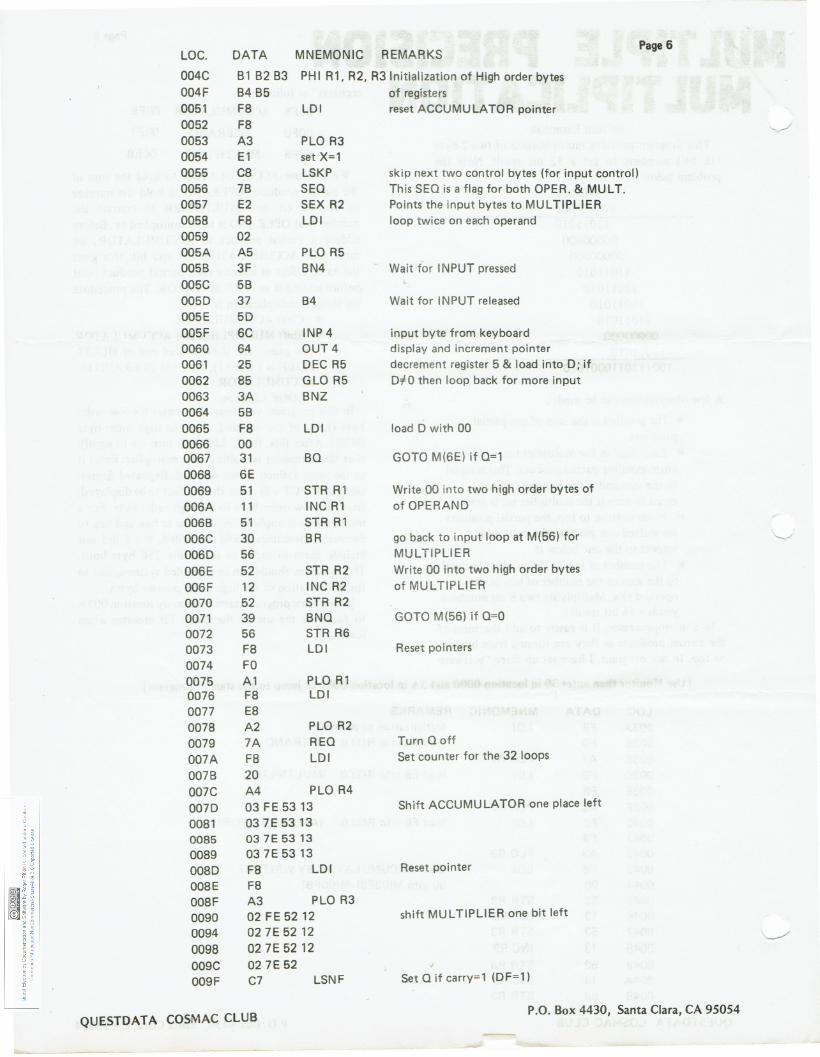
LOC. DATA MNEMONIC REMARKS Page 6
004C 81 82 83 PHI Rl, R2, R31nitialization of High order bytes 004F 84 85 of registers 0051 FB LDI reset ACCUMULATOR pointer 0052 FB 0053 A3 PLO R3 0054 El set X=1 0055 CB LSKP skip next two control bytes (for input control) 0056 78 SEQ This SEQ is a flag for both OPER. & MUL T. 0057 E2 SEX A2 Points the input bytes to MULTIPLIER 0058 FB LDI loop twice on each operand 0059 02 005A A5 PLO R5 0058 3F 8N4 Wait for INPUT pressed 005C 58 0050 37 84 Wait for INPUT released 005E 50 005F 6C INP4 input byte from keyboard 0060 64 OUT4 display and increment pointer 0061 25 DEC R5 decrement register 5 & load into D; if 0062 85 GLO R5 DiD then loop back for more input 0063 3A BNZ 0064 58 0065 FB LDI load D with 00 0066 00 0067 31 80 GOTO M(6E) if 0=1 0068 6E 0069 51 STR R1 Write 00 into two high order bytes of 006A 11 INC Al of OPERAND 0068 51 STR Rl 006C 30 8R go back to input loop at M(56) for 006D 56 MULTIPLIER 006E 52 STR R2 Write 00 into two high order bytes 006F 12 INC R2 of MULTIPLIER 0070 52 STR R2 0071 39 8NO GOTO M(56) if 0=0 0072 56 STR R6 0073 FB LDI Reset pointers 0074 FO 0075 A1 PLO Rl 0076 F8 LDI 0077 E8 0078 A2 PLO R2 0079 7A REO Turn 0 off 007A F8 LDI Set counter for the 32 loops 0078 20 007C A4 PLO R4 0070 03 FE 53 13 Shift ACCUMULATOR one place left 0081 03 7E 53 13 0085 03 7E 53 13 0089 03 7E 53 13 008D F8 LDI Reset pointer OOBE F8 008F A3 PLO R3 0090 02 FE 52 12 shift MULTIPLIER one bit left 0094 027E5212 0098 02 7E 52 12 009C 02 7E 52 009F C7 LSNF Set Q if carry=1 (DF=1)
QUESTDATA COSMAC CLUB P.O. Box 4430, Santa Clara, CA 95054
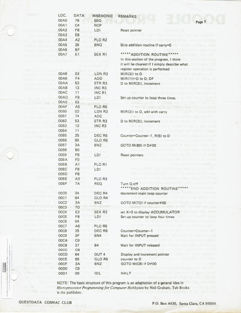
LOC. DATA MNEMONIC REMARKS OOAO 78 SEQ Page 7 ,..----.. OOA1 C4 NOP OOA2 F8 LDI Reset pointer
-..__/ OOA3 E8 OOA4 A2 PLO R2 OOA5 39 8NQ Skip addition routine if carry=O OOA6 8F OOA7 E1 SEX R1 *****ADDITION ROUTINE*****
In this section of the program, I think it will be clearest if I simply describe what register operation is performed
OOA8 03 LON R3 M(R(3)) to D OOA9 F4 ADD M(R(1'))+D to D, OF OOAA 53 STR R3 D to M(R(3)), increment OOA8 13 INC R3 OOAC 11 INC R1 OOAD F8 LDI Set up counter to loop three times OOAE 03 OOAF A5 PLO R5 0080 03 LON R3 M(R(3)) to D, add with carry 0081 74 ADC 0082 53 STR R3 D to M(R(3)), increment 0083 13 INC R3 0084 11 0085 25 DEC R5 Counter=Counter-1, R(5) to D 0086 85 GLO R5 0087 3A 8NZ GOTO M(80) if 0#00 0088 80
v 0089 F8 LDI Reset pointers 008A FO 0088 A1 PLO R1 008C F8 LDI 0080 F8 008E A3 PLO R3 008F 7A REO Turn Q off
*****END ADDITION ROUTINE***** ooco 24 DEC R4 decrement main loop counter OOC1 84 GLO R4 OOC2 3A 8NZ GOTO M(7D) if counter#OO OOC3 70 OOC4 E3 SEX R3 set X=3 to display ACCUMULATOR OOC5 FS LDI Set up counter to loop four times OOC6 04 OOC7 A5 PLO R5 ooca 25 DEC R5 Counter=Counter-1 OOC9 3F 8N4 Wait for INPUT pressed OOCA C9 OOC8 37 84 Wait for INPUT released oocc CB OOCD 64 OUT4 Display and increment pointer OOCE 85 GLO R5 counter to D OOCF 3A 8NZ GOTO M(C8) if 0#00 0000 C8 0001 00 iOL HALT
NOTE: The basic structure of this program is an adaptation of a general idea in Microprocessor Programming for Computer Hobbyists by Neil Graham, Tab Books is the publisher.
QUESTDATA COSMAC CLUB P.O. Box 4430, Santa Clara, CA 95054
DOODLE PROGRAM Page 8
By Jay Mallin Perhaps the best feature of your Super Elf-and
possibly the one that persuaded you to buy it-is its video graphics ability . No other micro in the same price range can do video graphics.
However, displaying pictures and designs can take some work. First you might fmd yourself coloring in little squares on graph paper to make the design, then coding all those little squares into hex.
This program, a doodler, simplifies the process to the point of fun by allowing you to draw on your screen as you watch by controlling a blinking cursor. Using the keyboard you can move the cursor in any direction and both write and erase with it. And while it might look best on an expanded Super Elf with a full page or more for the display, it was specifically designed to fit into a half page of memory , for use in an unexpanded Super Elf.
The program works via a blinking cursor, a single bit in size. The cursor bit is stored as a byte with 7 zeros and a one in RA.O, with its address in the display in R4 . The cursor is moved by manipulating the information in these two registers.
For example , to move the cursor on the screen left one place, the byte in RA .O is shifted left once. To move the cursor up one, eight is subtracted from R4, since 8 bytes less in memory is displayed on the screen as one line up . Moving diagonally is done with a combination of these two.
The program then writes RA.O into M(R4) so the cursor shows up on the screen . The information in R4 and RA.O is also used to write or erase in the cursor bit's location, under instructions from the keyboard.
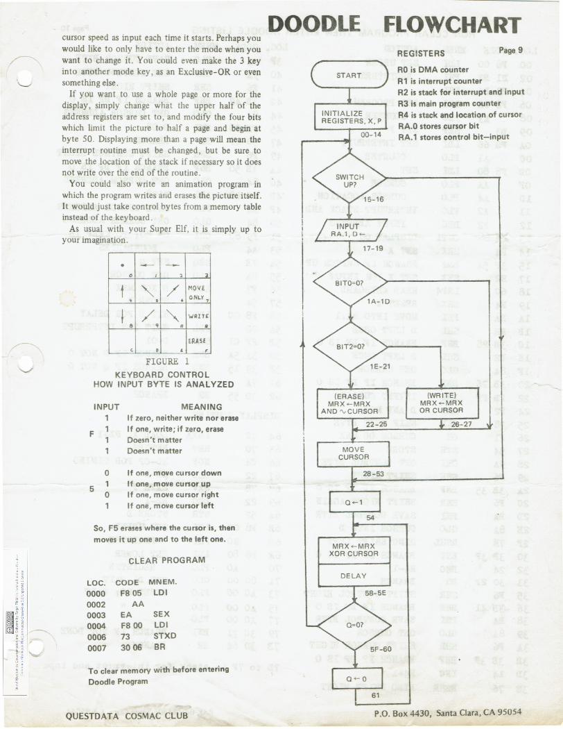
The computer reads instructions from the keyboard whenever the INPUT switch is depressed. Each bit in the control byte read tells it whether or not to per-form a separate operation (see figure 1). As an exam-ple, the first bit, bit 0, tells it whether to merely move the cursor or if it should perform a write or erase. Other bits in the control byte tell the program what combinations of directions to move the cursor.
The program has a few interesting internal features . One is the use of the 00 instruction in a loop to pro-duce a delay. It causes the computer to idle until a display interrupt occurs. The 00 instruction is also used in the interrupt display routine between each line of the display, instead of the two E2s that are normally used to waste four cycles. Here the 00 causes the computer to wait for DMA, and saves space.
To use the program (this is the part you were look-ing for, right?), first clear the memory. If you don't already have a program to do this, a small one is pro-vided that will leave just two bytes in the memory. (It's possible to write a program that will clear all but one byte-try it sometime.) Simply pul in the clear
QUESTDAT A COSMAC CLUB
program and press GO. The 0 state light will flash for an instant and the program will have done its work.
Now enter the doodle program, checking for mis-takes. When it is entered correctly, press GO. A blink-ing square will appear in the upper left hand corner of the screen. The bottom half is filled with the pro-gram, the top half of the picture is blank except for the blinking cursor.
To use the program, use the diagram of your key-board (figure 1). The nine keys with arrows will move the cursor in the direction of the arrow. The 7, B, and F are the mode keys. First you push a mode button, then a direction button, then hold down the INPUT switch.
Try 7 A, or "move only , down and to the right." The blinking cursor will move in that direction as long as you hold the INPUT switch down . Then try B4, or "write upward ." To erase that , use F8 , or "erase downward." Play a while , just remember to always push a mode key first, then a direction. Other combinations can have unpredictable effects. If some-thing goes wrong, you probably hit the wrong keys . Just push reset and restart the program. Also , you are welcome to try to move the cursor out of the picture area .
After a while, you may notice you have a screen filled with strange designs and no fast way to clear it. Try doing the following :
• Stop the program and put 01 in address 59 without changing any other bytes (remember the monitor changes address 20).
• Now start the program again . The cursor will appear as a gray square . You've
shortened the delay, and so sped it up. Push F2 and hold the INPUT switch down . The cursor will streak through each bit, erasing everything. Now try writing with the speeded up cursor. You can send it in one diagonal direction for a while and then the other for unusual patterns. Use it to turn the whole screen white, then put OC back in address 59 to slow the cursor back down. You can then draw in the negative , with the write as erase and vice versa .
For one last trick, use the cursor at normal speed to draw a figure like a square . Then put the 01 in 59 to speed everything up, and an F3 (Exclusive-OR) into 26. Start the program, push B2 , and hold down INPUT. The cursor will turn the picture into a neg-ative of itself. Keep holding it down, and it will change back into the original. The Exclusive-OR inverts each bit, changing it into what it wasn't before. The program uses the same idea to flash the cursor, inverting a bit, pausing, then inverting again.
Using more memory there are a number of ways to go further. You could have the program take the
(Continued on next page)
P.O. Box 4430, Santa Clara, CA 95054
cursor speed as input each time it starts. Perhaps you would like to only have to enter the mode when you want to change it. You could even make the 3 key into another mode key, as an Exclusive-OR or even something else.
If you want to use a whole page or more for the display, simply change what the upper half of the address registers are set to, and modify the four bits which limit the picture to half a page and begin at byte 50 . Displaying more than a page will mean the interrupt routine must be changed, but be sure to move the location of the stack if necessary so it does not write over the end of the routine .
You could also write an animation program in which the program writes and erases the picture itself. It would just take control bytes from a memory table instead of the keyboard.
As usual with your Super Elf, it is simply up to your imagination .
• - -0 I 3
t / MOV£
• • , 0 NLY 7
t / "" WRITE: e q A II
ERAS£ c. p • F
FIGURE l KEYBOARD CONTROL
HOW INPUT BYTE IS ANALYZED
INPUT MEANING
F 1 1 1
If zero, neither write nor erase If one, write; if zero, erase Doesn't matter Doesn't matter
0 If one, move cursor down
5 1 0
If one, move cursor up If one, move cursor right
1 If one, move cursor left
So, F5 erases where the cursor is, then moves it up one and to the left one.
CLEAR PROGRAM
LOC. CODE MNEM. 0000 F8 05 LDI 0002 AA 0003 EA SEX 0004 F8 00 LDI 0006 73 STXD 0007 30 06 BR
To clear memory with before entering Doodle Program
QUESTDAT A COSMAC CLUB
DOODLE
(ERASE) MRX<-MRX
AND rv CURSOR
MRX <-MRX XOR CURSOR
DELAY
FLOWCHART REGISTERS Page 9
RO is DMA counter R1 is interrupt counter R2 is stack for interrupt and input R3 is main program counter R4 is stack and location of cursor RA.O stores cursor bit RA.1 stores control bit-input
(WRITE) MRX<-MRX OR CURSOR
26-27
P.O. Box 4430, Santa Clara, CA 95054
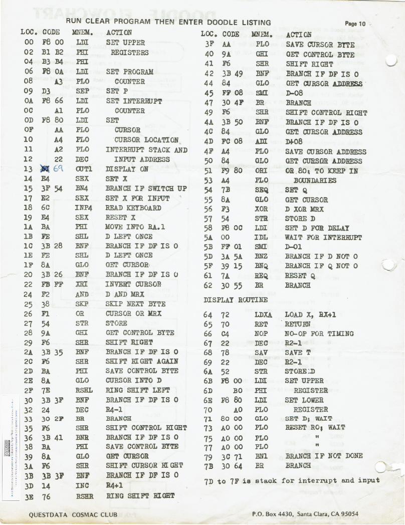
RUN CLEAR PROGRAM THEI\I ENTER DOODLE LISTING Page 10 . LOC. CODE l4NEM. ACTION LOO. CODE w.ru. ACTION 00 F8 00 LDI SNr UPPER 3F ll PLO SAVE CURSOR BYTE 02 :81 B2 PHI REGISTERS 40 9A GHI GET CONTROL BYTE 04 B3 :B4 PHI 41 F6 SHR Slii F'l' RIGHT 06 r8 OA LDI SET PROGRAM 42 3B 49 B.NF BRANCH IF DF IS 0 08 1.3 PLO COUNTER 44 84 GLO GET WRSOR ADDRESS . 09 D3 SEP SET P 45 FF 08 SLU D-08 OA F8 66 LDI SET INTERmJPT 47 30 4F BR BRANCH oc A1 PLO COUNTER 49 F6 SHR SHIF'll CONTROL BIGHT OD F8 80 LDI SET 4A 3B 50 :ma' BRANCH IF DF IS 0 OF AA PLO etmsOR 4C 84 GLO GE'l! OORS OR ADDRESS 10 A4 PLO -CURSOR LOCATION 4D FC 08 .ADI Df.08 11 A2 PLO INTERRUPT STACK AND 4F A4 PLO SAVE CURSOR ADDRESS 12 22 DEC INPUT ADDRESS 50 84 GLO GET CUliSOR ADDRESS 13 E/\ CX1Tl msPLAY ON 51 F9 80 ORI OR . Bo, TO ICEEP IN 14 E4 SEX SET X 53 A4 PLO :BWNDARIES 15 3F 54 :BN4 BRANCH IF SWITCH UP 54 7B SEQ SET Q 17 E2 SEX SE'l' X FCR INPUT 55 8A GLO GET CURSOR 18 6C INP4 READ KEYBOARD 56 F3 XOR D XOR lmX 19 E4 SEX RESET X 57 54 STR STORE D lA BA PHI l40VE INTO RA.l 58 Ft3 oc LDI SFl' D FOR DELAY l:B FE SRL D LEF'l' ONCE 5A 00 IDL WAIT FOR IBTERRUPr lC 3B 28 BNF BRANCH IF DF IS 0 5B FF 01 SMI D-Ol lE FE SRL D LEFI' ONCE 5D 3A 5A lmZ BRANCH IF D NCII' 0 1F 8A GLO GET CURSOR' 5F 39 15 BNQ BRANCH IF Q BeYr 0 20 .3B 26 BNF BRANCH IF DF IS 0 61 1A. REQ RES.m'Q 22 FB FF XBI INVElll' CURSOR 62 30 55 BR BRANCH 24 F2 .Alrn D AND MRX
DISPLAY RCUTINE 25 38 SKP SKIP NEXT BYTE 26 Fl. OR CURSOR OR J!RX 64 72 LDXA LOAD X, lU+l 27 54 STR STORE 65 70 RET RETURN 28 9A GEI GET CONTROL BYTE 66 C4 NOP NO-OP FOR TIUING 29 F6 SHR SHIFT RIGHT 67 22 DEC R2-l 2A JB 35 BNF BRANCH IF DF IS 0 68 78 SAV SAVE T 2C F6 SHR SKI i'l' RIGHT AGAIN 69 22 DEC R2-l 2D BA ffil SAVE CONTROL BYTE 6A 52 STB. STOREi.D 2E 8A GLO CURSOR INTO D 6B iS 00 Llli SET UPPER 2F 7E RSHL RING SRI F'l' LEF'l' 6D BO PHI REGISTER 30 3B 3F BNF BRANCH IF DF IS 0 6E F88o LDI SET LOWER 32 24 DEC R4-l 70 AO PLO REGISTER 33 30 2P' BR :BRANCH 71 80 00 OLO SET D; WAIT
35 F6 SHR SHIF'l' CONTROL RIGHT 73 AO 00 PLO RESET ROJ WAIT 36 3B 41 BNR BRANCH IF DF IS 0 75 AO 00 PLO " 38 BA PHI SAVE CONTROL BYTE 77 AO 00 PLO " 39 8A GLO GET CURSOR 79 30 71 BNl BRANCH IF NC!l' DONE 3.A. F6 SRR SRI FT CURSOR RIGHT 7B 30 64 BR BRANCH
"---" 3B 3B 3F BNF BRANCH IF DF IS 0 7D to 7F i s staok for interrupt and input
3D 14 INC R4+1 3E 76 RSHR BING SRI FT BI OHT
QUESTDAT A COSMAC CLUB P.O. Box 4430, Santa Clara, CA 95054
Page 11
NEW PATTERNS By Mike Tyborski
Graphics is an extremely interesting and enjoyable application for personal computers. It is through its use that games, art and animated effects are created.
The Quest Electronics Super Elf provides bit-mapped graphics capabilities on a budget, using the CDP1861 video IC. Through proper programming, display res-olutions up to 64Hx182V dots may be obtained and complex animated effects are possible.
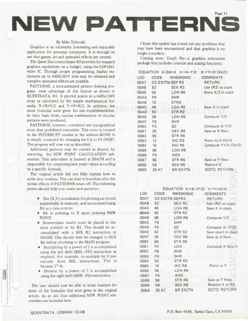
PATTERNS, a semi-animated pattern drawing pro-gram, took advantage of this feature as shown in QUESTDATA #6. It plotted points in a 64Hx128V array as calculated by the simple mathematical for-mula; X:=X+Y/2 and Y:=Y+X/2. In addition, ten more formulas were given for user experimentation. In their basic form, various combinations of circular patterns were produced.
PATTERNS, however, contained one typographical error that prohibited execution. This error is located in the INTERRUPT routine at the address 0019H. It is simply corrected by changing the CA to C4 (NOP). The program will now run as described.
Additional patterns may be created as desired, by rewriting the NEW POINT CALCULATION sub-routine. This subroutine is located at OOA7H and is responsible for computing new point values according to a specific formula.
The original article did not fully explain how to write new routines. This can lead to boredom after the initial effects of PATTERNS wears off. The following points should help you create new patterns:
• The (X,Y) coordinates for plotting are stored sequentially in memory, and are accessed using R6 as a data pointer.
• R6 is pointing to X upon entering NEW POINT.
• Intermediate results must be placed in the stack pointed to by R2. This should be ac-complished with a SEX R2 instruction at OOA8H. This should then be changed to SEX R6 before returning to the MAIN program.
• Multiplying by a power of 2 is accomplished using the left shift (SHL- FE) instruction as required. For example , to multiply by 8 just execute three SHL instructions. This is because 23 =8.
• Division by a power of 2 is accomplished using the right shift (SHR- F6) instruction.·
The user should now be able to write routines for most of the formulas that were given in the original article. As an aid , four additional NEW POINT sub-routines are included here .
QUESTDATA COSMAC CLUB
I hope this update has ironed out any problems that may have been encountered and that graphics is no longer a mystery.
Coming soon: Graph Pac-a graphics subroutine package that includes rotation and scaling functions.
EQUATION X Old=X X:=X-Y/2 X:=Y+(X Old/2) LOC CODE MNEMONIC COMMENTS OOA7 03 EXITN:SEP R3 RETURN OOAB E2 SEX R2 Use (R2) as stack OOA9 06 LON R6 Store X/2 in stack OOAA F6 SHR OOA8 73 STXD OOAC 46 LOA R6 Save X in stack OOAD 52 STR R2 OOAE 06 LON R6 Compute Y/2 OOAF F6 SHR 0080 F5 so Compute X-Y/2 0081 26 DEC R6 Save as X New 0082 56 STR R6 0083 12 INC R2 Point to X Old/2 0084 16 INC R6 Compute Y+(X Old/2) 0085 06 LON R6 0086 F4 ADD 0087 56 STR R6 Save as Y New 0088 E6 SEX R6 ·Restore X 0089 30A7 8R EXITN GOTO RETURN
EQUATION X:=X-(Y/2) Y:=Y+(X/4) LOC CODE MNEMONIC COMMENTS OOA7 03 EXITN:SEPR3 .RETURN OOA8 E2 SEX R2 ·Use (R2) as stack OOA9 46 LOA R6 Save X in stack OOAA 52 STR R2 OOA8 06 LON R6 Compute Y/2 OOAC F6 SHR OOAD F5 so Compute X-(Y /2) OOAE 52 STR R2 Save result in stack OOAF 26 DEC R6 Save as X New 0080 56 STR R6 0081 FO LOX Compute X New/4 0082 F6 SHR 0063 F6 SHR 0084 52 STR R2 0085 16 INC R6 Point toY 0086 06 LON R6 0087 F4 ADD 0088 56 STR R6 Save as Y New 0089 E6 SEX R6 Restore X to R6 OOBA 30A7 BR EXITN GOTO RETURN
P.O. Box 4430, Santa Clara, CA 95054
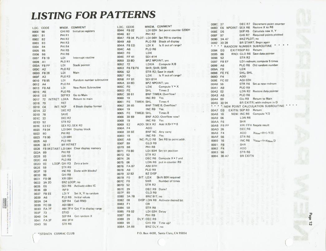
LISTING FOR PATTERNS LOC. CODE 0000 90 0001 B1 0002 B2 0003 B3 0004 B4 0005 B5 0006 B6 0007 F8 19 0009 A1 OOOA FB FF OOOC A2 OOOD F8 28 OOOF A3 0010 F895 0012 A4 0013 FB AS 0015 A5
MNEM. COMMENT GHI RO Initialize registers PHIR1 PHIR2 PHI R3 PHIR4 PHIR5 PHIR6 LDI Interrupt routine PLO R1 LDI Stack pointer PLO R2 LD I Main PLO R3 LD I Random number subroutine PLO R4 LDI New Point Subroutine PLO R5
0016 03 SEPR3 GotoMain 0017 72 INTRET: LDXA Return to main 0018 70 0019 C4 001A 22 001B 78 001C 22 0010 52 DOlE E2 E2 0020 FB 04 0022 BO 0023 F8 00
RET INT: NOP
DEC R2 SAVE DEC R2 STR R2
4 Block display format
SEX R2; SEX R2 LDI 04H Display block PHIRO LDI OOH
0025 AO PLO RO 0026 30 17 BR INTRET 0028 F8 04START:LDI 04H Clear display memory 002A B9 PHI R9 002B 93 GHI R3 002C A9 002D 93 002E 59 002F 19 0030 99 0031 FB 08 0033 3A 2D 0035 E6 0036 69 0037 F8 EE 0039 A6 003A D4 003B FC OB 0030 FA 7F 003F 73 0040 D4 0041 FA 3F 0043 56
PLO R9 LOOP: GHI R3 Zero a byte
STR R9 INC R9 Done with blocks? GHI R9 XRI OBH BNZ LOOP; no SEX R6 Activate video IC INP9 LDI Y Set X, Y to random PLO R6 Initial values SEP R4 Call RND ADI OBH ANI 7FH Get Yin display range STXD SEP R4 Get random X ANI 3FH STR R6
\ . 'C:STDATA COSMAC CLUB
LOC. CODE 0044 FS 02
MNEM. COMMENT LDI 02H Set point counter 0200H
0046 B7 PHI R7 0047 FS 04 PLOT: LDI 04H Set R9 to starting
Block of display Is X out of range?
0049 A9 PLO R9 004A F8 ED LDI X 004C A6 0040 FO 004E FF 41 0050 33 80 0052 72
PLO R6 LOX SDI41H BPZ NPOINT; yes LDXA Compute X/8
0053 F6 F6 F6 0056 52
SHR; SHR; SHR STR R2; Save in stack
0057 FO 0058 FF 81 005A 33 SO 005C FO
LOX Is Y out of range? SDIS1H BPZ NPOINT; yes LOX Compute Y • X
0050 FE SHL Times 2 005C 3B 61 BNF TIME4; Overflow? 0060 19 INC R9 Yes 0061 FE TIME4: SHL Times4 0062 3B 65 BNF TIMES; Overflow? 0064 19 INC R9 Yes 0065 FE TIMES: SHL Times S 0066 3B 69 BNF ADD; Overflow now? 0068 19 INC R9 Yes 0069 E2 ADD: SEX R2 Add X/S+Y • S 006A F4 006B 3B 6E 006D 19 006E AS 006F 89 0070 BB 0071 F8 80 0073 52 0074 26 0075 06 0076 FA 07 007S A9 0079 32 S2 007B FO 007C F6 007D 52 007E 29 007F 89 OOBO 3A 7B 0082 OS 0083 F1 0084 58 OOS5 F8 02 0087 B9 0088 29 0089 99 008A 3A 88
ADD BN F NC Any carry INC R9 Yes
NC: PLO RB Set R8 to point addr. GLO R9 PHI R8 LD I SOH Set bit position STR R2 DEC R6 Compute X • 7 and LON R6 put in counter R9 ANI 07H PLO R9 BZ DISP
BIT: LOX SHR STR R2
Shift SOH required Number of times
DEC R9 Done? GLO R9 BNZ BIT; no
DISP LON R8 Activate des ired bit OR STR RS LOI 02H Delay PHI R9
DLY: DEC R9 GHI R9 Time up? BNZ DLY; no
P.O. Box 4430, Santa Clara, CA 95054
(
OOSC 27 DEC R7 Decrement point counter OOBD E6 NPOINT: SEX R6 Restore X to R6 OOBE D5 SEP R5 Calculate new X, Y 008F 97 GH I R7 Required points plotted 0090 3A 47 BNZ PLOT; no 0092 30 2S BR START; Begin again * * * * RANDOM NUMBER SUBROUTINE * 0094 03 EXITRSEP R3 Return 0095 86 RND: GLO R6 Save data pointer 0096 52 STR R2 0097 FS EF 0099 A6 009A FO 009B FE FE 0090 F4 009E FC 02 OOAO 56 OOA1 A9 OOA2 02 OOA3 A6
LDI rndnum; compute 5 times PLO R6 Old random number LOX SHL; SHL ADD ADI 02H STR R6 Set as new rndnum PLO R9 LON R2 Restore data pointer PLO R6
OOA4 S9 Glo R9 Return to Main OOA5 30 94 BR EXITR; with rndnum in D * * * * NEW POINT CALCULATION SUBROUTINE OOA7 03 SEP R3 Return OOAS 16 NEW: INC R6 Compute Y/2 OOA9 06 LON R6 OOAA F6 OOAB FB FF OOAD 26 OOAE F4 OOAF 56 OOBO 16 OOB1 F6 OOB2 F4 OOB3 56 OOB4 30 A7
SHR XRI FFH Negate result DEC,R6 ADD XNew=X+(- Y /2) STR R6 INC R6 YNew =Y+XNew/2 SHR ADD STR R6 BR EXITN
l
I» '8 .... N
NEW PATTERNS (Cont inued)
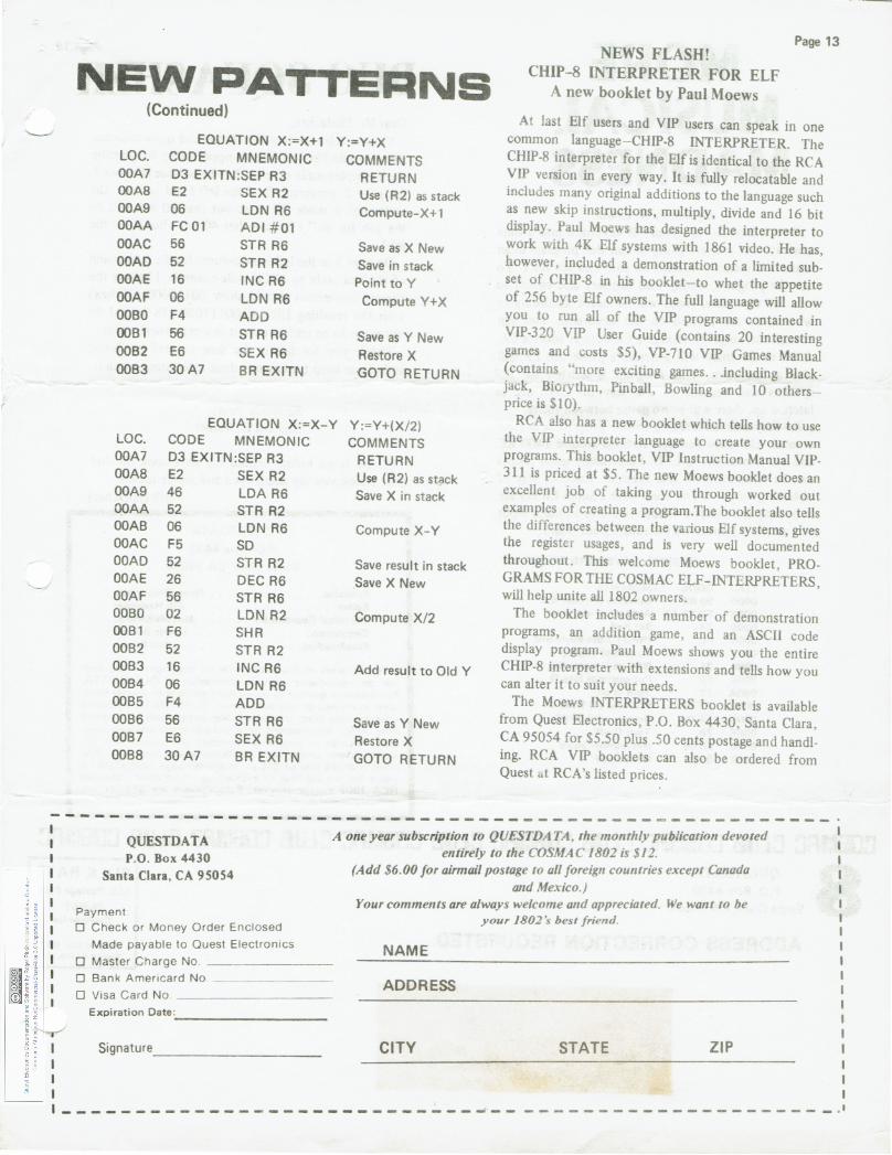
...._____, EQUATION X :=X+1 Y :=Y+X
LOC. CODE MNEMONIC COMMENTS OOA7 03 EXITN :SEP R3 RETURN OOA8 E2 SEX R2 Use (R2) as stack OOA9 06 LON R6 Compute-X+1 OOAA FC 01 ADI # 01 OOAC 56 STR R6 Save as X New OOAD 52 STR R2 Save in stack OOAE 16 INC R6 Point toY OOAF 06 LON R6 Compute Y+X 0080 F4 ADD 0081 56 ST R R6 Save as Y New 0082 E6 SEX R6 Restore X 0083 30A7 8 R EXITN .GOTO RETURN
EQUAT ION X :=X- Y Y:=Y+(X/2) LOC. CODE MNEMON IC COMMENTS OOA7 03 EXITN:SEP R3 RETURN OOA8 E2 SEX R2 Use (R2) as stack OOA9 46 LDA R6 Save X in stack OOAA 52 STR R2 OOA8 06 LDN R6 Compute X-Y OOAC F5 so OOAD 52 ST R R2 Save result in stack OOAE 26 DEC R6 Save X New OOAF 56 STR R6 0080 02 LON R2 Compute X/2 008 1 F6 SHR 0082 52 STR R2 0083 16 INC R6 Add result to Old Y 0084 06 LDN R6 0085 F4 ADD 0086 56 STR R6 Save as Y New 0087 E6 SEX R6 Restore X 0088 30A7 8R EXITN GOTO RETURN
NEWS FLASH! CHIP-8 INTERPRETER FOR ELF
A new booklet by Paul Moews
Page 13
At last Elf users and VIP users can speak in one common language-CHIP-8 INTERPRETER. The CHIP-8 interpreter for the Elf is identical to the RCA VIP version in every way. It is fully relocatable and includes many original additions to the language such as new skip instructions, multiply, divide and 16 bit display. Paul Moews has designed the interpreter to work with 4K Elf systems with 1861 video. He has, however, included a demonstration of a limited sub-set of CHIP-8 in his booklet-to whet the appetite of 256 byte Elf owners. The full language will allow you to run all of the VIP programs contained in VIP-320 VIP User Guide (contains 20 interesting games and costs $5), VP-710 VIP Games Manual (contains "more exciting games . . .including Black-jack, Biorythm, Pinball, Bowling and 10 others-price is $1 0).
RCA also has a new booklet which tells how to use the VIP interpreter language to create your own programs. This booklet, VIP Instruction Manual VIP-311 is priced at $5. The new Moews booklet does an excellent job of taking you through worked out examples of creating a program. The booklet also tells the differences between the various Elf systems, gives the register usages, and is very well documented throughout. This welcome Moews booklet, PRO-GRAMS FOR THE COSMAC ELF-INTERPRETERS, will help unite all 1802 owners.
The booklet includes a number of demonstration programs, an addition game, and an ASCII code display program. Paul Moews shows you the entire CHIP-8 interpreter with extensions and tells how you can alter it to suit your needs.
The Moews INTERPRETERS booklet is available from Quest Electronics, P.O. Box 4430, Santa Clara, CA 95054 for $5.50 plus .50 cents postage and handl-ing. RCA VIP booklets can also be ordered from Quest at RCA's listed prices.
-----------------------------------------------------QUESTDATA P.O. Box 4430
Santa Clara, CA 95054
Payment. 0 Check or Mo ney Order Enc losed
Made payable to Quest Electronics 0 Master Charge No. ____ _ 0 Bank Amencard No ______ _
A one year subscription to QUESTDATA, tile mollth/y publication devoted entirely to tile COSMAC 1802 is $12.
(Add $6.00 for airmail postage to all foreign countries except Canada and Mexico.)
Your comments are always welcome and appreciated. We want to be you r 1802's best friend.
NAME
0 Visa Card No. _ _______ _ ADDRESS Expiratio n Date::__ _______ _
Signature. _________ _ CITY STATE ZIP
I - - - - - - - - - -- - - -- - - - - - - - - - - - - - .,.. - - - - - - - - - - - - - - - - - - - - - - - · '
MORE MUSICAL MADNESS
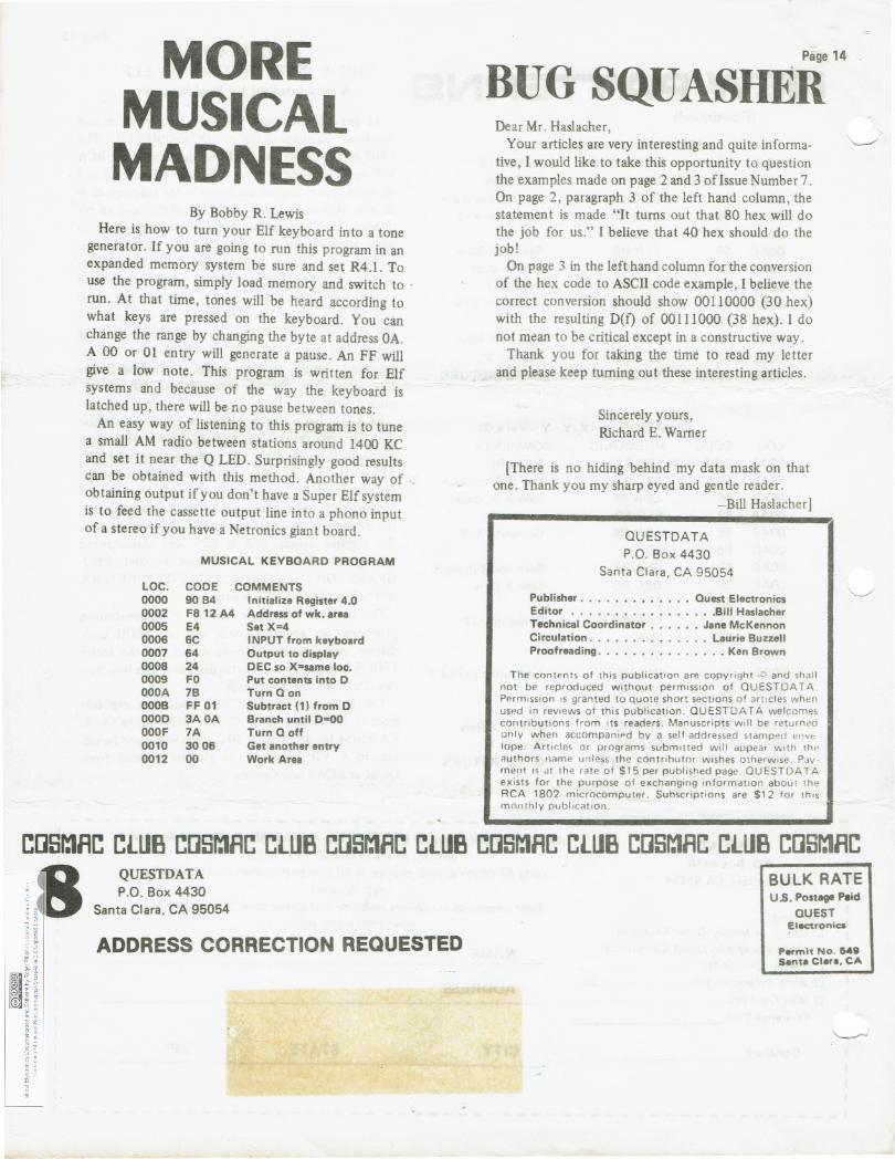
By Bobby R. Lewis Here is how to turn your Elf keyboard into a tone
generator. If you are going to run this program in an expanded memory system be sure and set R4.1 . To use the program, simply load memory and switch to run. At that time, tones will be heard according to what keys are pressed on the keyboard. You can change the range by changing the byte at address OA. A 00 or 01 entry will generate a pause. An FF will give a low note. This program is written for Elf systems and because of the way the keyboard is latched up, there will be no pause between tones.
An easy way of listening to this program is to tune a small AM radio between stations around 1400 KC and set it near the Q LED. Surprisingly good results can be obtained with this method . Another way of obtaining output if you don't have a Super Elf system is to feed the cassette output line into a phono input of a stereo if you have a Netronics giant board.
MUSICAL KEYBOARD PROGRAM
LOC. CODE COMMENTS 0000 90 84 Initialize Register 4.0 0002 FS 12 A4 Address of wk. area 0005 E4 Set X=4 0006 6C INPUT from keyboard 0007 64 Output to display 0008 24 DEC so X=same loc. 0009 FO Put contents into D OOOA 7B Turn Q on OOOB FF 01 Subtract ( 1) from D OOOD 3AOA Branch until D=OO OOOF 7A Turn Q off 0010 3006 Get another entry 0012 00 Work Area
Page 14
BUG SQUASHER Dear Mr. Haslacher,
Your articles are very interesting and quite informa· tive, I would like to take this opportunity to question the examples made on page 2 and 3 oflssue Number 7. On page 2, paragraph 3 of the left hand column, the statement is made "It turns out that 80 hex will do the job for us." I believe that 40 hex should do the job!
On page 3 in the left hand column for the conversion of the hex code to ASCII code example, I believe the correct conversion should show 00110000 (30 hex) with the resulting D(f) of 00111000 (38 hex). I do not mean to be critical except in a constructive way.
Thank you for taking the time to read my letter and please keep turning out these interesting articles .
Sincerely yours, Richard E. Warner
[There is no hiding behind my data mask on that one. Thank you my sharp eyed and gentle reader.
-Bill Haslacher]
OUESTDATA P.O. Box 4430
Santa Clara, CA 95054
Publisher . . . . . . . • . . • . . Ouest Electronics Editor •..• ....••••..... Bill Haslacher Technical Coordinator . . . . . . Jane McKennon Circulation .. ••.•........ Laurie Buzzell Proofreading . . . . • • . • • . . . . .. Ken Brown
The contents of this publication are copyright ,C) and shall not be reproduced without permission of QUESTDA T A . Perm1ssion 1s granted to quote short sections of art1cles when usP.d in reVH)WS of this publication. QUESTOATA welcomes contributions from i ts readers. Manuscripts will be returned only when accompaniPd by a self -addressed stamped lope. Artir.les or programs submitted will aj.lpear w1th thP authors name unless the contributor wishes otherw•se. PJv· rnent 1s ill the rate of $15 per published page. OUESTDATA exists for the purpose of exchanging information about the RCA 1802 microcomputer. Subscriptions are $1 2 for th1s monthly publication .
LlUB L[]Sr:lflC 8 QUESTDATA P.O. Box 4430
Santa Clara, CA 95054
ADDRESS CORRECTION REQUESTED
BULK RATE U.S. -Postage Paid
QUEST Elearonics
Parmh No. &4Q Santa Clara, CA


![Homework 9: Software Design Considerations · The PIC24F series has a separate 16-bit wide data memory space, divided into byte addressable blocks (8 bits) [1]. Byte addresses 0x0000](https://img.pdfslide.us/doc/110x75/5e72aa6435ceab51450255e9/homework-9-software-design-considerations-the-pic24f-series-has-a-separate-16-bit.jpg)