Embed Size (px)
Citation preview
Auhtor TD-XTRACT LAN G3 Specifications Rev 2.0
Telecom Design Page 1 04/02/10 Technical Department
TD-XTRACT LAN
• 10/100 Base T Auto Sensing • 3.3V operation • Robust and Fast TCP/IP stack
including TCP, IP, UDP, ICMP, DHCP, BOOTP, ARP, DNS.
• Up to 5 simultaneous connections
• Berkeley socket interface
• AT interface ( modem emulation )
• Multi-sockets framed interface • Completely Integrated Solution • CE compliant • Extended Operating
Temperature ( -40 to +90 °C) • Remote broadcast configurable
Auhtor TD-XTRACT LAN G3 Specifications Rev 2.0
Telecom Design Page 2 04/02/10 Technical Department
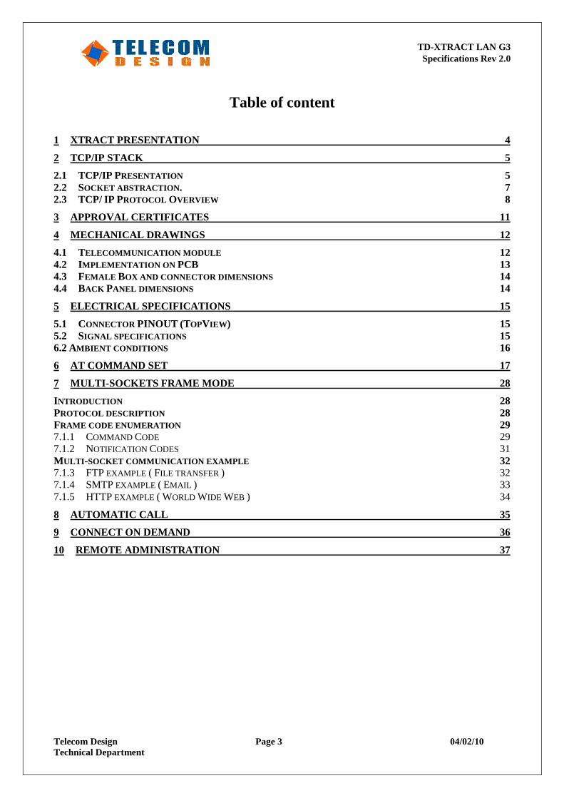
RECORD of REVISIONS
Revision Date Details Rev 1.0 27/04/05 Draft Rev 1.1 06/07/05 Added automatic call feature and remote configuration Rev 1.3 05/09/05 Added remote configuration password protection and ATQ1 Rev 1.4 19/05/06 Connector Pinout Rev 1.5 19/06/06 Added AT Commands : AT-, AT@C, AT&C, AT&S, Connect On Demand and
Connection timeout Rev 1.6 16/11/06 Connector Pinout (Link & Aout) Rev 1.7 23/02/06 DNS multisocket supported Rev 1.8 14/05/07 Mechanical drawings Rev 1.9 09/10/08 Add notice Rev 2.0 04/02/10 Add power consumption
Auhtor TD-XTRACT LAN G3 Specifications Rev 2.0
Telecom Design Page 3 04/02/10 Technical Department
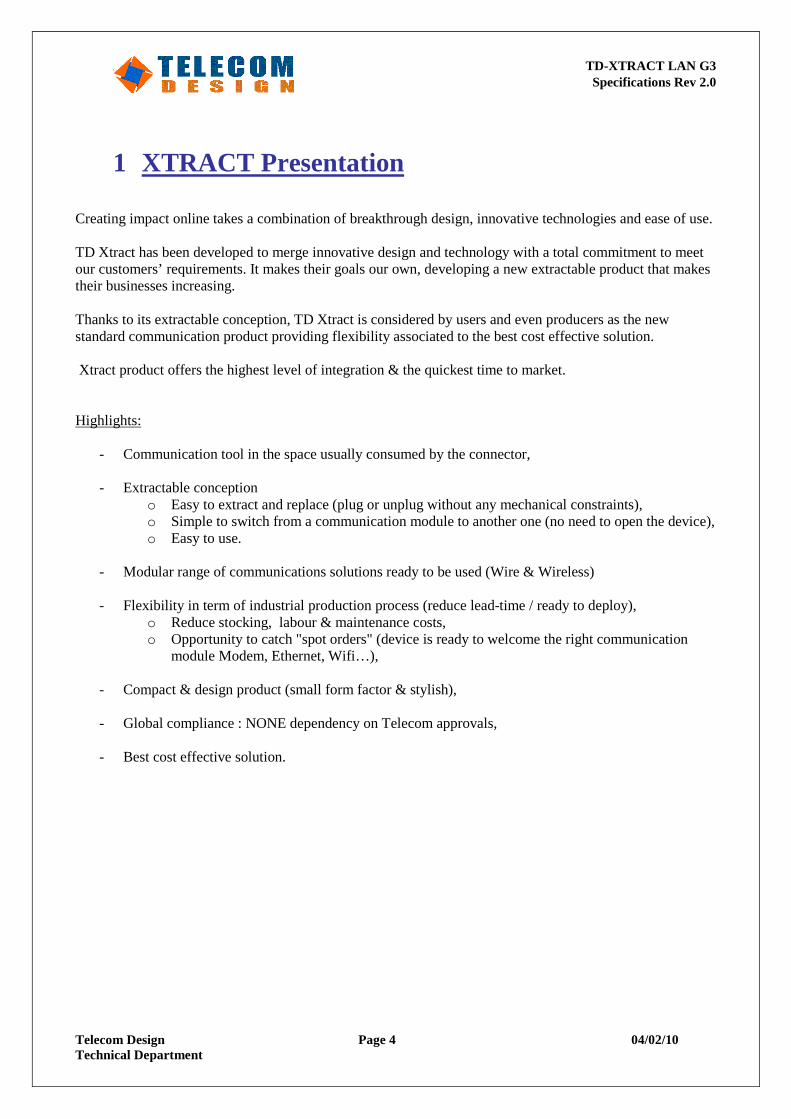
Table of content
1 XTRACT PRESENTATION 4
2 TCP/IP STACK 5
2.1 TCP/IP PRESENTATION 5 2.2 SOCKET ABSTRACTION . 7 2.3 TCP/ IP PROTOCOL OVERVIEW 8
3 APPROVAL CERTIFICATES 11
4 MECHANICAL DRAWINGS 12
4.1 TELECOMMUNICATION MODULE 12 4.2 IMPLEMENTATION ON PCB 13 4.3 FEMALE BOX AND CONNECTOR DIMENSIONS 14 4.4 BACK PANEL DIMENSIONS 14
5 ELECTRICAL SPECIFICATIONS 15
5.1 CONNECTOR PINOUT (TOPVIEW ) 15 5.2 SIGNAL SPECIFICATIONS 15 6.2 AMBIENT CONDITIONS 16
6 AT COMMAND SET 17
7 MULTI-SOCKETS FRAME MODE 28
INTRODUCTION 28 PROTOCOL DESCRIPTION 28 FRAME CODE ENUMERATION 29 7.1.1 COMMAND CODE 29 7.1.2 NOTIFICATION CODES 31 MULTI -SOCKET COMMUNICATION EXAMPLE 32 7.1.3 FTP EXAMPLE ( FILE TRANSFER ) 32 7.1.4 SMTP EXAMPLE ( EMAIL ) 33 7.1.5 HTTP EXAMPLE ( WORLD WIDE WEB ) 34
8 AUTOMATIC CALL 35
9 CONNECT ON DEMAND 36
10 REMOTE ADMINISTRATION 37
Auhtor TD-XTRACT LAN G3 Specifications Rev 2.0
Telecom Design Page 4 04/02/10 Technical Department
1 XTRACT Presentation Creating impact online takes a combination of breakthrough design, innovative technologies and ease of use. TD Xtract has been developed to merge innovative design and technology with a total commitment to meet our customers’ requirements. It makes their goals our own, developing a new extractable product that makes their businesses increasing. Thanks to its extractable conception, TD Xtract is considered by users and even producers as the new standard communication product providing flexibility associated to the best cost effective solution. Xtract product offers the highest level of integration & the quickest time to market. Highlights:
- Communication tool in the space usually consumed by the connector, - Extractable conception
o Easy to extract and replace (plug or unplug without any mechanical constraints), o Simple to switch from a communication module to another one (no need to open the device), o Easy to use.
- Modular range of communications solutions ready to be used (Wire & Wireless) - Flexibility in term of industrial production process (reduce lead-time / ready to deploy),
o Reduce stocking, labour & maintenance costs, o Opportunity to catch "spot orders" (device is ready to welcome the right communication
module Modem, Ethernet, Wifi…),
- Compact & design product (small form factor & stylish), - Global compliance : NONE dependency on Telecom approvals,
- Best cost effective solution.
Auhtor TD-XTRACT LAN G3 Specifications Rev 2.0
Telecom Design Page 5 04/02/10 Technical Department
2 TCP/IP Stack
2.1 TCP/IP Presentation
Introduction
This document describes the TCP/IP software stack included in the Telecom Design Modem products. TCP/IP stack require layers to connect application (ie: ftp, http,… ) to a distant server through a point to point line. The different layers embedded inside the modem are:
o Physical / Link layer o Internet / Network layer o Transport Layer o Session Layer
This document also describes all the protocols supported by Telecom Design TCP/IP stack with a quick description of each. Use and configuration procedure will be described in a second step. The main application of this embedded stack is to connect to a private network through a media port 10BT or 100BT. Embedded TCP/IP reduces host CPU load used for TCP connection. Host just needs to manage application layer (SMTP, FTP, HTTP). All other layers are transparent because embedded in the socket modem. TCP/IP stack can be managed by AT command or by a simple protocol.
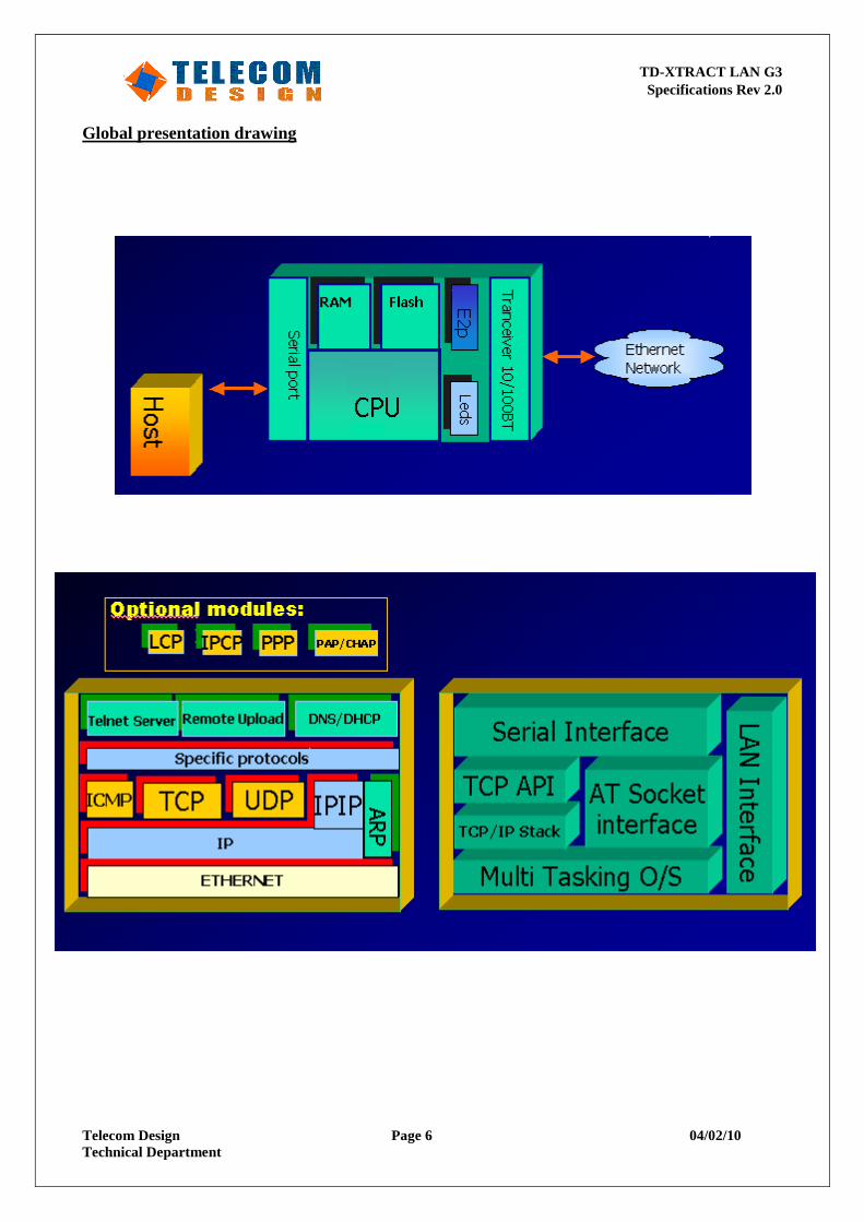
Global Presentation
Host interface: Host communicates with TCP/IP modem through an asynchronous serial junction. The serial DTE channel is able to transfer speed up to 115200bps. Distant system interface: Modem is able to communicate with a private Ethernet server through DHCP, DNS protocols.
Auhtor TD-XTRACT LAN G3 Specifications Rev 2.0
Telecom Design Page 6 04/02/10 Technical Department
Global presentation drawing
Auhtor TD-XTRACT LAN G3 Specifications Rev 2.0
Telecom Design Page 7 04/02/10 Technical Department
2.2 Socket abstraction.
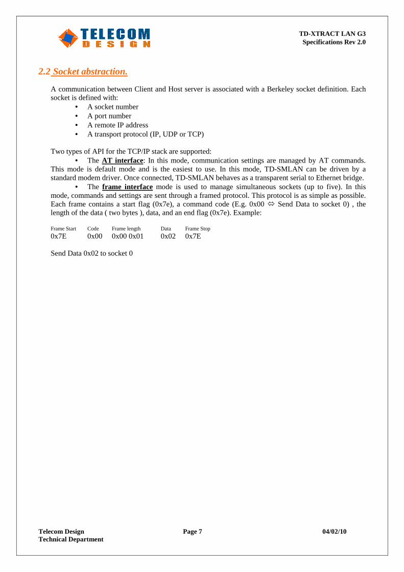
A communication between Client and Host server is associated with a Berkeley socket definition. Each socket is defined with:
• A socket number • A port number • A remote IP address • A transport protocol (IP, UDP or TCP)
Two types of API for the TCP/IP stack are supported:
• The AT interface: In this mode, communication settings are managed by AT commands. This mode is default mode and is the easiest to use. In this mode, TD-SMLAN can be driven by a standard modem driver. Once connected, TD-SMLAN behaves as a transparent serial to Ethernet bridge.
• The frame interface mode is used to manage simultaneous sockets (up to five). In this mode, commands and settings are sent through a framed protocol. This protocol is as simple as possible. Each frame contains a start flag (0x7e), a command code (E.g. 0x00 � Send Data to socket 0) , the length of the data ( two bytes ), data, and an end flag (0x7e). Example: Frame Start Code Frame length Data Frame Stop
0x7E 0x00 0x00 0x01 0x02 0x7E Send Data 0x02 to socket 0
Auhtor TD-XTRACT LAN G3 Specifications Rev 2.0
Telecom Design Page 8 04/02/10 Technical Department
2.3 TCP/ IP Protocol Overview
IP
IP layer is able to connect a local system (defined with local IP address) to a remote system (defined with remote IP address) through a shared network. Local IP address could be static (set manually by user) or dynamic (set automatically by remote server). IP protocol includes multiplexing and routing functions. IP is associated with ICMP protocol to monitor network communication errors, configuration and congestion. IP is the Internet's most basic protocol. In order to function in a TCP/IP network, a network segment's only requirement is to forward IP packets. In fact, a TCP/IP network can be defined as a communication medium that can transport IP packets. Almost all other TCP/IP functions are constructed by layering atop IP. IP is documented in RFC 791, and IP broadcasting procedures are discussed in RFC 919. IP is a data gram-oriented protocol, treating each packet independently. This means each packet must contain complete addressing information. Also, IP makes no attempt to determine if packets reach their destination or to take corrective action if they do not. Nor does IP checksum the contents of a packet, only the IP header.
IP provides several services: • Addressing. IP headers contain 32-bit addresses, which identify the sending and receiving hosts.
These addresses are used by intermediate routers to select a path through the network for the packet.
• Fragmentation. IP packets may be split, or fragmented, into smaller packets. This allows a large packet to travel across a network, which can only handle smaller packets. IP fragments and reassembles packets transparently.
• Packet timeouts. Each IP packet contains a Time To Live (TTL) field, which is decremented every time a router handles the packet. If TTL reaches zero, the packet is discarded, preventing packets from running in circles forever and flooding a network.
• Type of Service. IP supports traffic prioritization by allowing packets to be labelled with an abstract type of service.
• Options. IP provides several optional features, allowing a packet's sender to set requirements on the path it takes through the network (source routing), trace the route a packet takes (record route), and label packets with security features.
UDP/TCP
UDP and TCP are directly associated with IP. UDP and TCP are concurrent. Indeed the application uses either UDP or TCP to send data through a network. Services offered by UDP and TCP multiplex data from different applications. Port numbers should be defined by user to separate TCP/UDP channel. Local Port number is associated with host application. Remote Port number is associated with remote application. TCP is a very reliable data protocol. It includes Flow control and quality services. UDP requires less resource but is less reliable.
Auhtor TD-XTRACT LAN G3 Specifications Rev 2.0
Telecom Design Page 9 04/02/10 Technical Department
TCP
The Transmission Control Protocol (TCP), documented in RFC 793, makes up for IP's deficiencies by providing reliable, stream-oriented connections that hide most of IP's shortcomings. The protocol suite gets its name because most TCP/IP protocols are based on TCP, which is in turn based on IP. TCP and IP are the twin pillars of TCP/IP. TCP adds a great deal of functionalities to the IP services, it is layered over: • Streams. TCP data is organized as a stream of bytes, much like a file. The datagram nature of
the network is concealed. A mechanism (the Urgent Pointer) exists to let out-of-band data be specially flagged.
• Reliable delivery. Sequence numbers are used to coordinate which data has been transmitted and received. TCP will arrange for retransmission if it determines that data has been lost.
• Network adaptation. TCP will dynamically learn the delay characteristics of a network and adjust its operation to maximize throughput without overloading the network.
• Flow control. TCP manages data buffers, and coordinates traffic so its buffers will never overflow. Fast senders will be stopped periodically to keep up with slower receivers.
Full-duplex Operation No matter what the particular application, TCP almost always operates full-duplex. The algorithms described below operate in both directions, in an almost completely independent manner. It's sometimes useful to think of a TCP session as two independent byte streams, travelling in opposite directions. No TCP mechanism exists to associate data in the forward and reverse byte streams. Only during connection start and close sequences can TCP exhibit asymmetric behaviour (i.e. data transfer in the forward direction but not in the reverse, or vice versa). Sequence Numbers TCP uses a 32-bits sequence number that counts bytes in the data stream. Each TCP packet contains the starting sequence number of the data in that packet, and the sequence number (called the acknowledgment number) of the last byte received from the remote peer. With this information, a sliding-window protocol is implemented. Forward and reverse sequence numbers are completely independent, and each TCP peer must track both its own sequence numbering and the numbering being used by the remote peer. TCP uses a number of control flags to manage the connection. Some of these flags pertain to a single packet, such as the URG flag indicating valid data in the Urgent Pointer field, but two flags (SYN and FIN), require reliable delivery as they mark the beginning and end of the data stream. In order to insure reliable delivery of these two flags, they are assigned spots in the sequence number space. Each flag occupies a single byte. Window Size and Buffering Each endpoint of a TCP connection will have a buffer for storing data that is transmitted over the network before the application is ready to read the data. This lets network transfers take place while applications are busy with other processing, improving overall performance. To avoid overflowing the buffer, TCP sets a Window Size field in each packet it transmits. This field contains the amount of data that may be transmitted into the buffer. If this number falls to zero, the remote TCP can send no more data. It must wait until buffer space becomes available and it receives a packet announcing a non-zero window size. Sometimes, the buffer space is too small. This happens when the network's bandwidth-delay product exceeds the buffer size. The simplest solution is to increase the buffer, but for extreme cases the protocol itself becomes the bottleneck (because it doesn't support a large enough Window Size). Under these conditions, the network is termed an LFN (Long Fat Network - pronounced elephant). RFC 1072 discusses LFNs. Round-Trip Time Estimation When a host transmits a TCP packet to its peer, it must wait a period of time for an acknowledgment. If the reply does not come within the expected period, the packet is assumed to have been lost and
Auhtor TD-XTRACT LAN G3 Specifications Rev 2.0
Telecom Design Page 10 04/02/10 Technical Department
the data is retransmitted. The obvious question - How long do we wait? - lacks a simple answer. Over an Ethernet, no more than a few microseconds should be needed for a reply. If the traffic must flow over the wide-area Internet, a second or two might be reasonable during peak utilization times. If we're talking to an instrument package on a satellite hurtling toward Mars, minutes might be required before a reply. There is no one answer to the question - How long? All modern TCP implementations seek to answer this question by monitoring the normal exchange of data packets and developing an estimate of how long is "too long". This process is called Round-Trip Time (RTT) estimation. RTT estimates are one of the most important performance parameters in a TCP exchange, especially when you consider that on an indefinitely large transfer, all TCP implementations eventually drop packets and retransmit them, no matter how good the quality of the link. If the RTT estimate is too low, packets are retransmitted unnecessarily; if too high, the connection can sit idle while the host waits to timeout.
UDP
UDP, documented in RFC 768, provides user access to IP-like services. UDP packets are delivered just like IP packets - connection-less data grams that may be discarded before reaching their targets. UDP is useful when TCP would be too complex, too slow, or just unnecessary. UDP provides a few functions beyond that of IP: • Port Numbers. UDP provides 16-bit port numbers to let multiple processes use UDP services on
the same host. A UDP address is the combination of a 32-bit IP address and the 16-bits port number.
• Check summing. Unlike IP, UDP does checksum its data, ensuring data integrity. A packet failing checksum is simply discarded, with no further action taken.
DNS
Domain name system. This application is included in TCP/IP stack. It is used to transform Domain name (www.telecom-design.com) to IP address (xxx.yyy.zzz.www) . DNS embedded management is totally transparent for host.
DHCP
DHCP is used to get the client configuration from the server (IP address, Sub Mask value, Gateway address, DNS address).
BOOTP
BOOTP is used to set the IP address client configuration provided by the server.
TD-XTRACT LAN G3 Specifications Rev 1.8
Telecom Design Page 11 04/02/10 Technical Department
3 Approval Certificates The TD-SMLAN is approved for the following standards: Approved EN55022 (Emissions EMC) approval CLASSB OK EN55024 (Immunity EMC) approval CLASSB OK In Process… FCC Part15 CLASSB OK UL60950 and Canadian Standard C22.2 approved
TD-XTRACT LAN G3 Specifications Rev 1.8
Telecom Design Page 12 04/02/10 Technical Department
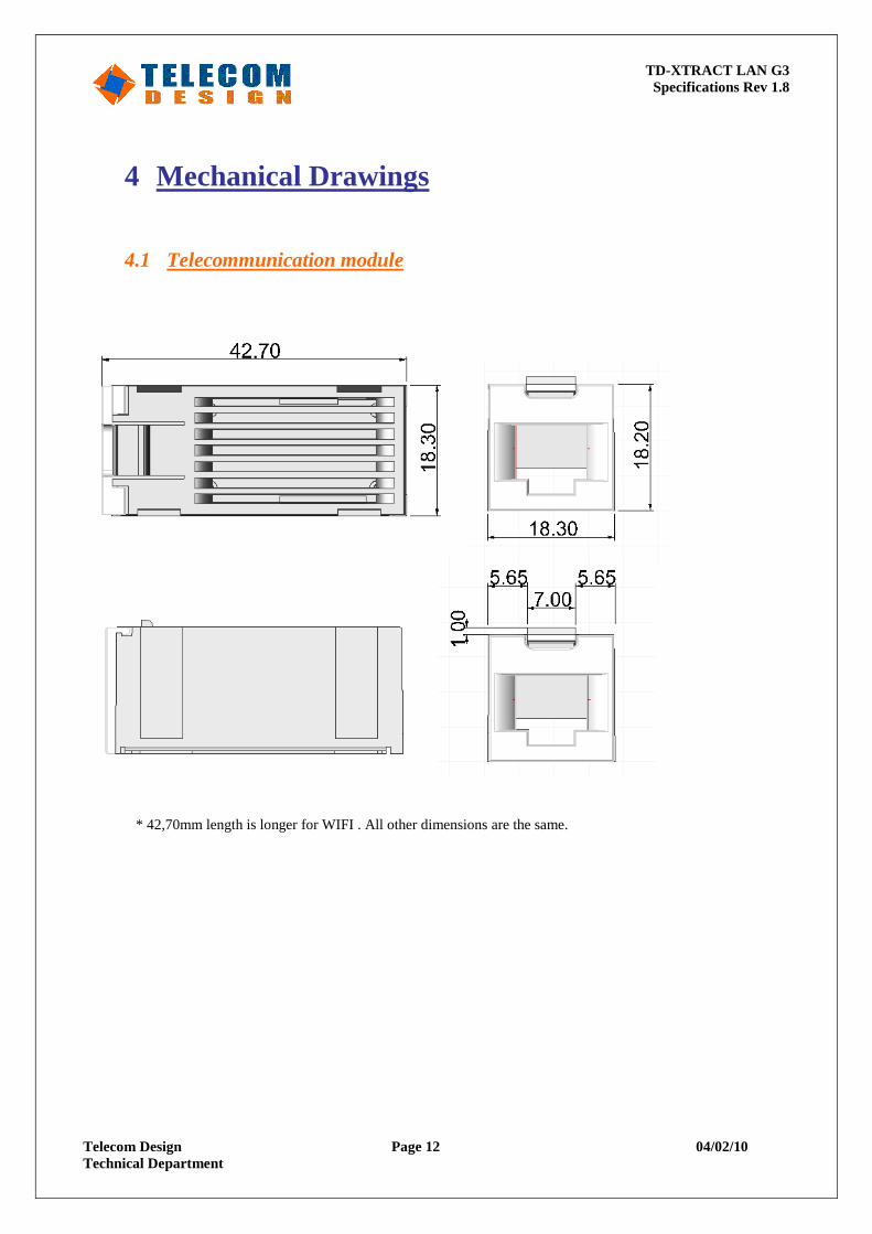
4 Mechanical Drawings
4.1 Telecommunication module
* 42,70mm length is longer for WIFI . All other dimensions are the same.
TD-XTRACT LAN G3 Specifications Rev 1.8
Telecom Design Page 13 04/02/10 Technical Department
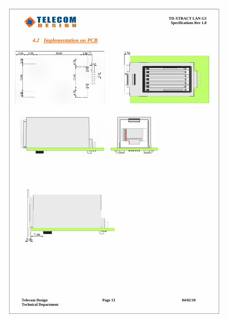
4.2 Implementation on PCB
TD-XTRACT LAN G3 Specifications Rev 1.8
Telecom Design Page 14 04/02/10 Technical Department
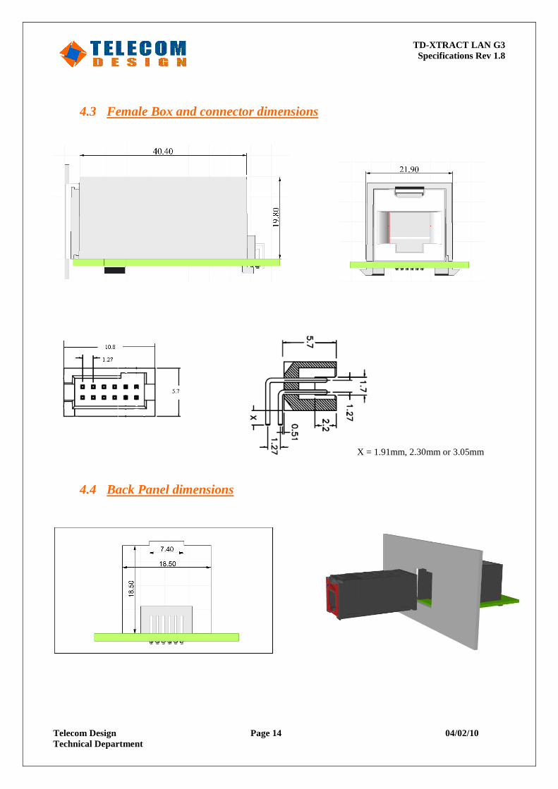
4.3 Female Box and connector dimensions
X = 1.91mm, 2.30mm or 3.05mm
4.4 Back Panel dimensions
TD-XTRACT LAN G3 Specifications Rev 1.8
Telecom Design Page 15 04/02/10 Technical Department
5 Electrical specifications
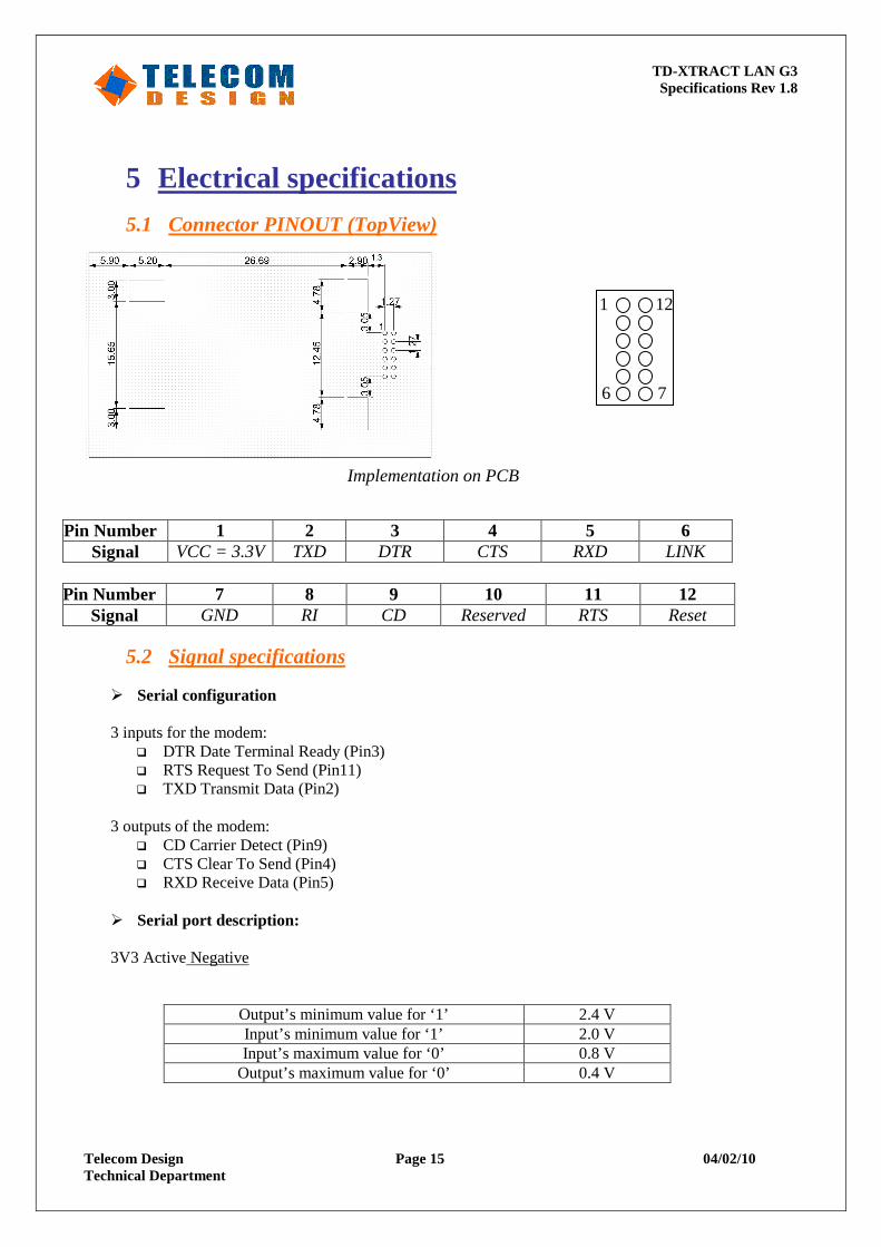
5.1 Connector PINOUT (TopView)
Pin Number 1 2 3 4 5 6 Signal VCC = 3.3V TXD DTR CTS RXD LINK
Pin Number 7 8 9 10 11 12
Signal GND RI CD Reserved RTS Reset
5.2 Signal specifications
� Serial configuration 3 inputs for the modem:
� DTR Date Terminal Ready (Pin3) � RTS Request To Send (Pin11) � TXD Transmit Data (Pin2)
3 outputs of the modem:
� CD Carrier Detect (Pin9) � CTS Clear To Send (Pin4) � RXD Receive Data (Pin5)
� Serial port description:
3V3 Active Negative
Output’s minimum value for ‘1’ 2.4 V Input’s minimum value for ‘1’ 2.0 V Input’s maximum value for ‘0’ 0.8 V
Output’s maximum value for ‘0’ 0.4 V
1 12
6 7
Implementation on PCB
TD-XTRACT LAN G3 Specifications Rev 1.8
Telecom Design Page 16 04/02/10 Technical Department
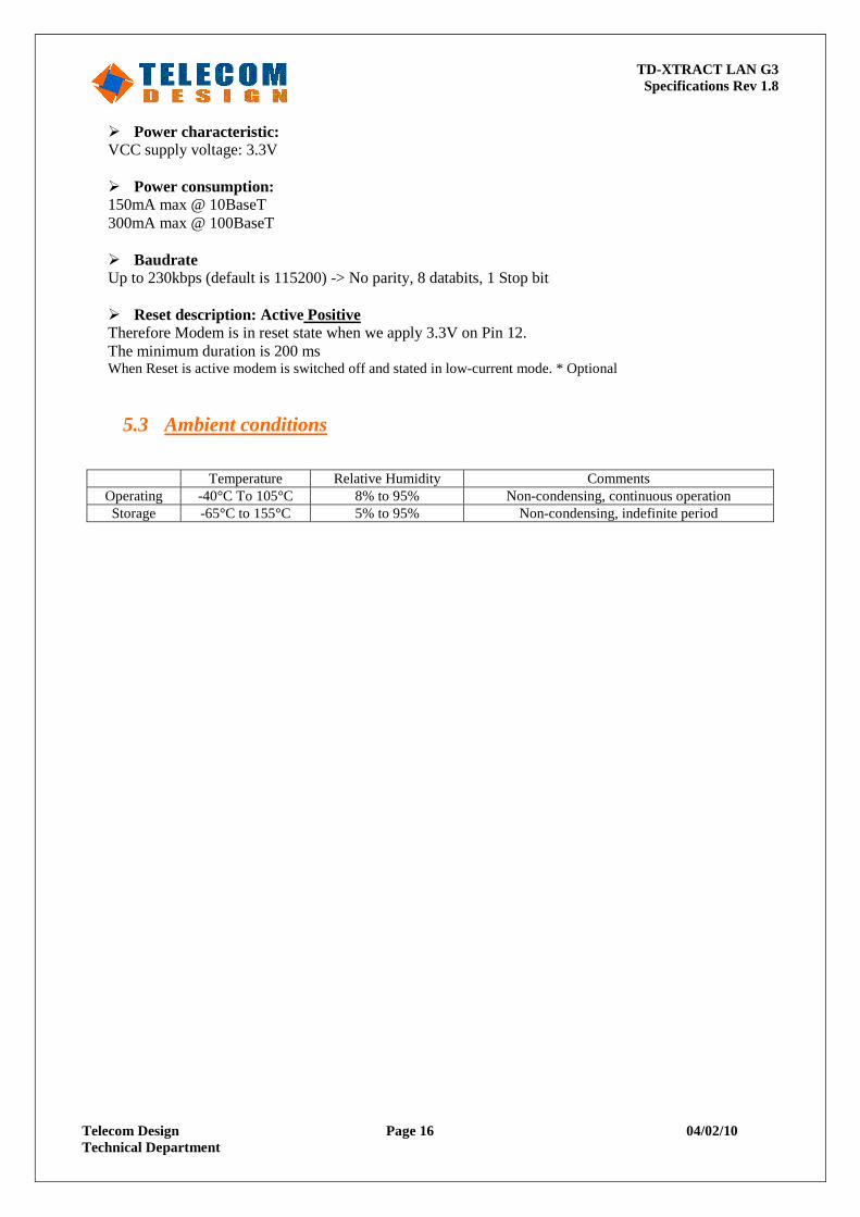
� Power characteristic: VCC supply voltage: 3.3V � Power consumption: 150mA max @ 10BaseT 300mA max @ 100BaseT
� Baudrate Up to 230kbps (default is 115200) -> No parity, 8 databits, 1 Stop bit
� Reset description: Active Positive Therefore Modem is in reset state when we apply 3.3V on Pin 12. The minimum duration is 200 ms When Reset is active modem is switched off and stated in low-current mode. * Optional
5.3 Ambient conditions
Temperature Relative Humidity Comments
Operating -40°C To 105°C 8% to 95% Non-condensing, continuous operation Storage -65°C to 155°C 5% to 95% Non-condensing, indefinite period
TD-XTRACT LAN G3 Specifications Rev 1.8
Telecom Design Page 17 04/02/10 Technical Department
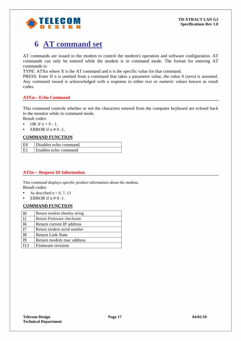
6 AT command set AT commands are issued to the modem to control the modem's operation and software configuration. AT commands can only be entered while the modem is in command mode. The format for entering AT commands is: TYPE: ATXn where X is the AT command and n is the specific value for that command. PRESS: Enter If n is omitted from a command that takes a parameter value, the value 0 (zero) is assumed. Any command issued is acknowledged with a response in either text or numeric values known as result codes. ATEn—Echo Command This command controls whether or not the characters entered from the computer keyboard are echoed back to the monitor while in command mode. Result codes: • OK if n = 0 - 1. • ERROR if n # 0 -1.
COMMAND FUNCTION
E0 Disables echo command. E1 Enables echo command ATIn— Request ID Information This command displays specific product information about the modem. Result codes: • As described n = 0, 7, 13 • ERROR if n # 0 -1.
COMMAND FUNCTION
I0 Return modem identity string
I1 Return Firmware checksum I6 Return current IP address I7 Return modem serial number I8 Return Link State I9 Return modem mac address I13 Firmware revision
TD-XTRACT LAN G3 Specifications Rev 1.8
Telecom Design Page 18 04/02/10 Technical Department
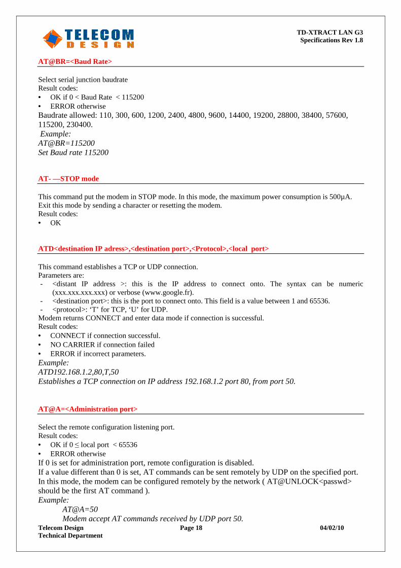
AT@BR=<Baud Rate> Select serial junction baudrate Result codes: • OK if 0 < Baud Rate < 115200 • ERROR otherwise Baudrate allowed: 110, 300, 600, 1200, 2400, 4800, 9600, 14400, 19200, 28800, 38400, 57600, 115200, 230400. Example: AT@BR=115200 Set Baud rate 115200 AT- —STOP mode This command put the modem in STOP mode. In this mode, the maximum power consumption is 500µA. Exit this mode by sending a character or resetting the modem. Result codes: • OK ATD<destination IP adress>,<destination port>,<Protocol>,<local port> This command establishes a TCP or UDP connection. Parameters are: - <distant IP address >: this is the IP address to connect onto. The syntax can be numeric
(xxx.xxx.xxx.xxx) or verbose (www.google.fr). - <destination port>: this is the port to connect onto. This field is a value between 1 and 65536. - <protocol>: ‘T’ for TCP, ‘U’ for UDP. Modem returns CONNECT and enter data mode if connection is successful. Result codes: • CONNECT if connection successful. • NO CARRIER if connection failed • ERROR if incorrect parameters. Example: ATD192.168.1.2,80,T,50 Establishes a TCP connection on IP address 192.168.1.2 port 80, from port 50. AT@A=<Administration port> Select the remote configuration listening port. Result codes: • OK if 0 ≤ local port < 65536 • ERROR otherwise If 0 is set for administration port, remote configuration is disabled. If a value different than 0 is set, AT commands can be sent remotely by UDP on the specified port. In this mode, the modem can be configured remotely by the network ( AT@UNLOCK<passwd> should be the first AT command ). Example:
AT@A=50 Modem accept AT commands received by UDP port 50.
TD-XTRACT LAN G3 Specifications Rev 1.8
Telecom Design Page 19 04/02/10 Technical Department
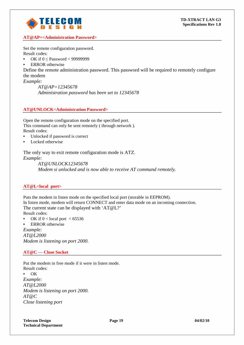
AT@AP=<Administration Password> Set the remote configuration password. Result codes: • OK if 0 ≤ Password < 99999999 • ERROR otherwise Define the remote administration password. This password will be required to remotely configure the modem Example:
AT@AP=12345678 Administration password has been set to 12345678
AT@UNLOCK<Administration Password> Open the remote configuration mode on the specified port. This command can only be sent remotely ( through network ). Result codes: • Unlocked if password is correct • Locked otherwise The only way to exit remote configuration mode is ATZ. Example:
AT@UNLOCK12345678 Modem si unlocked and is now able to receive AT command remotely.
AT@L<local port> Puts the modem in listen mode on the specified local port (storable in EEPROM). In listen mode, modem will return CONNECT and enter data mode on an incoming connection. The current state can be displayed with ‘AT@L?’ Result codes: • OK if 0 < local port < 65536 • ERROR otherwise Example: AT@L2000 Modem is listening on port 2000. AT@C — Close Socket Put the modem in free mode if it were in listen mode. Result codes: • OK Example: AT@L2000 Modem is listening on port 2000. AT@C Close listening port
TD-XTRACT LAN G3 Specifications Rev 1.8
Telecom Design Page 20 04/02/10 Technical Department
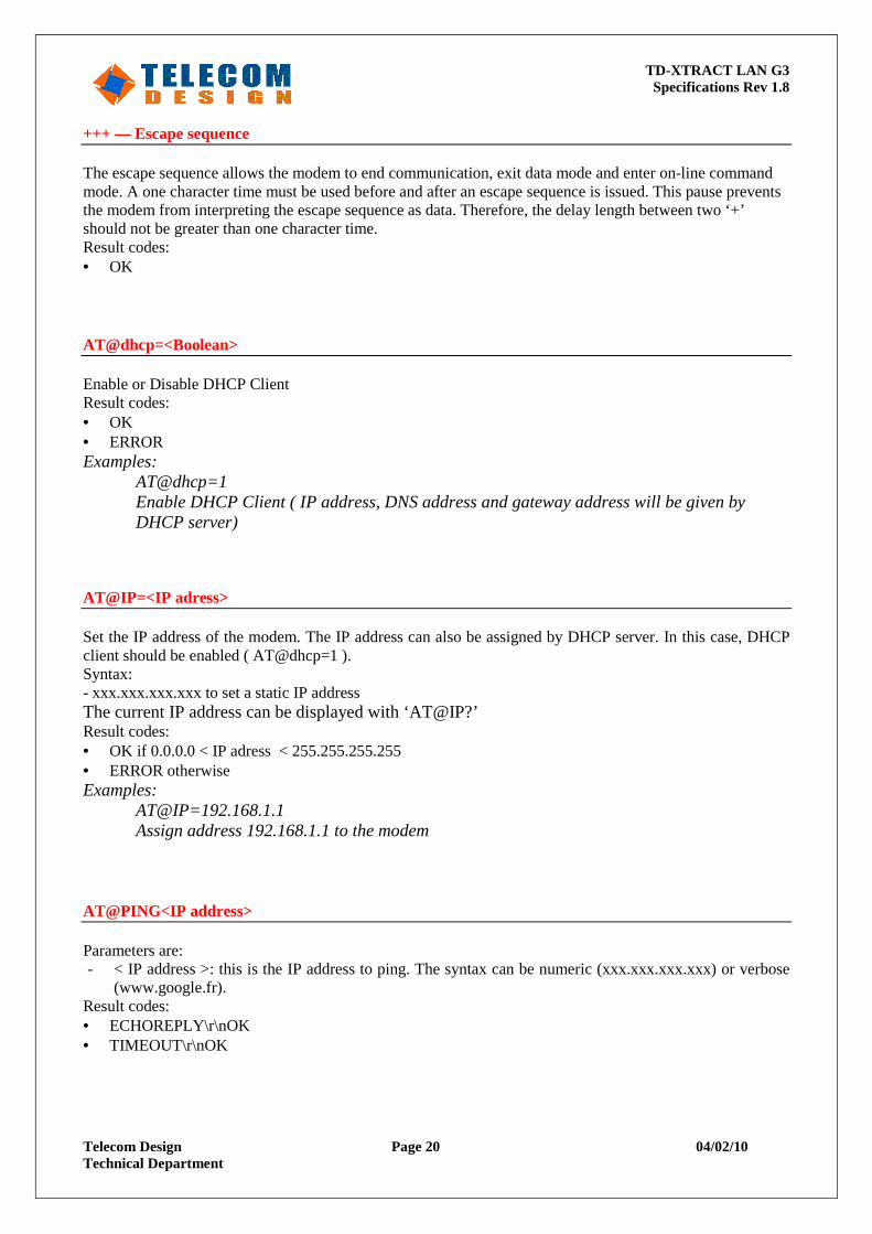
+++ — Escape sequence The escape sequence allows the modem to end communication, exit data mode and enter on-line command mode. A one character time must be used before and after an escape sequence is issued. This pause prevents the modem from interpreting the escape sequence as data. Therefore, the delay length between two ‘+’ should not be greater than one character time. Result codes: • OK AT@dhcp=<Boolean> Enable or Disable DHCP Client Result codes: • OK • ERROR Examples:
AT@dhcp=1 Enable DHCP Client ( IP address, DNS address and gateway address will be given by DHCP server)
AT@IP=<IP adress> Set the IP address of the modem. The IP address can also be assigned by DHCP server. In this case, DHCP client should be enabled ( AT@dhcp=1 ). Syntax: - xxx.xxx.xxx.xxx to set a static IP address The current IP address can be displayed with ‘AT@IP?’ Result codes: • OK if 0.0.0.0 < IP adress < 255.255.255.255 • ERROR otherwise Examples:
AT@IP=192.168.1.1 Assign address 192.168.1.1 to the modem
AT@PING<IP address> Parameters are: - < IP address >: this is the IP address to ping. The syntax can be numeric (xxx.xxx.xxx.xxx) or verbose
(www.google.fr). Result codes: • ECHOREPLY\r\nOK • TIMEOUT\r\nOK
TD-XTRACT LAN G3 Specifications Rev 1.8
Telecom Design Page 21 04/02/10 Technical Department
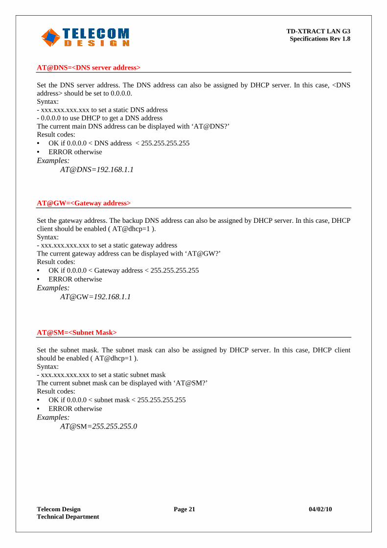
AT@DNS=<DNS server address> Set the DNS server address. The DNS address can also be assigned by DHCP server. In this case, <DNS address> should be set to 0.0.0.0. Syntax: - xxx.xxx.xxx.xxx to set a static DNS address - 0.0.0.0 to use DHCP to get a DNS address The current main DNS address can be displayed with ‘AT@DNS?’ Result codes: • OK if 0.0.0.0 < DNS address < 255.255.255.255 • ERROR otherwise Examples:
AT@DNS=192.168.1.1 AT@GW=<Gateway address> Set the gateway address. The backup DNS address can also be assigned by DHCP server. In this case, DHCP client should be enabled ( AT@dhcp=1 ). Syntax: - xxx.xxx.xxx.xxx to set a static gateway address The current gateway address can be displayed with ‘AT@GW?’ Result codes: • OK if 0.0.0.0 < Gateway address < 255.255.255.255 • ERROR otherwise Examples:
AT@GW=192.168.1.1 AT@SM=<Subnet Mask> Set the subnet mask. The subnet mask can also be assigned by DHCP server. In this case, DHCP client should be enabled ( AT@dhcp=1 ). Syntax: - xxx.xxx.xxx.xxx to set a static subnet mask The current subnet mask can be displayed with ‘AT@SM?’ Result codes: • OK if 0.0.0.0 < subnet mask < 255.255.255.255 • ERROR otherwise Examples:
AT@SM=255.255.255.0
TD-XTRACT LAN G3 Specifications Rev 1.8
Telecom Design Page 22 04/02/10 Technical Department
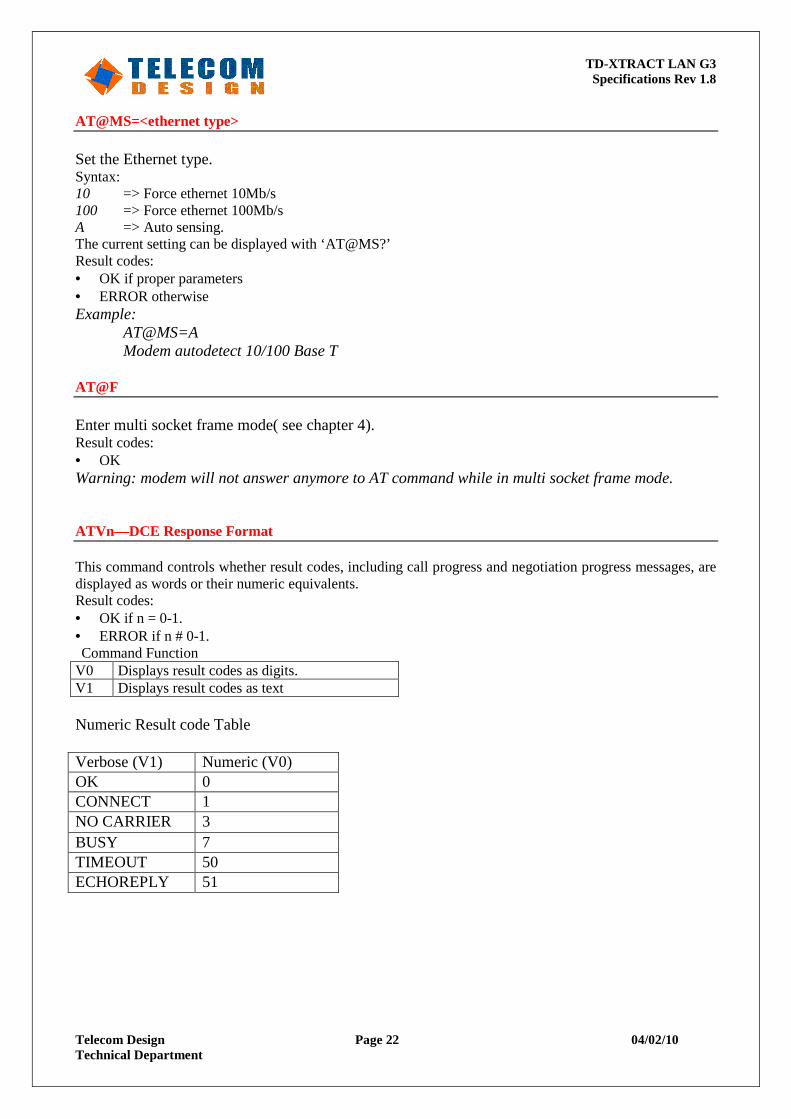
AT@MS=<ethernet type> Set the Ethernet type. Syntax: 10 => Force ethernet 10Mb/s 100 => Force ethernet 100Mb/s A => Auto sensing. The current setting can be displayed with ‘AT@MS?’ Result codes: • OK if proper parameters • ERROR otherwise Example:
AT@MS=A Modem autodetect 10/100 Base T
AT@F Enter multi socket frame mode( see chapter 4). Result codes: • OK Warning: modem will not answer anymore to AT command while in multi socket frame mode. ATVn—DCE Response Format This command controls whether result codes, including call progress and negotiation progress messages, are displayed as words or their numeric equivalents. Result codes: • OK if n = 0-1. • ERROR if n # 0-1. Command Function
V0 Displays result codes as digits. V1 Displays result codes as text Numeric Result code Table Verbose (V1) Numeric (V0) OK 0 CONNECT 1 NO CARRIER 3 BUSY 7 TIMEOUT 50 ECHOREPLY 51
TD-XTRACT LAN G3 Specifications Rev 1.8
Telecom Design Page 23 04/02/10 Technical Department
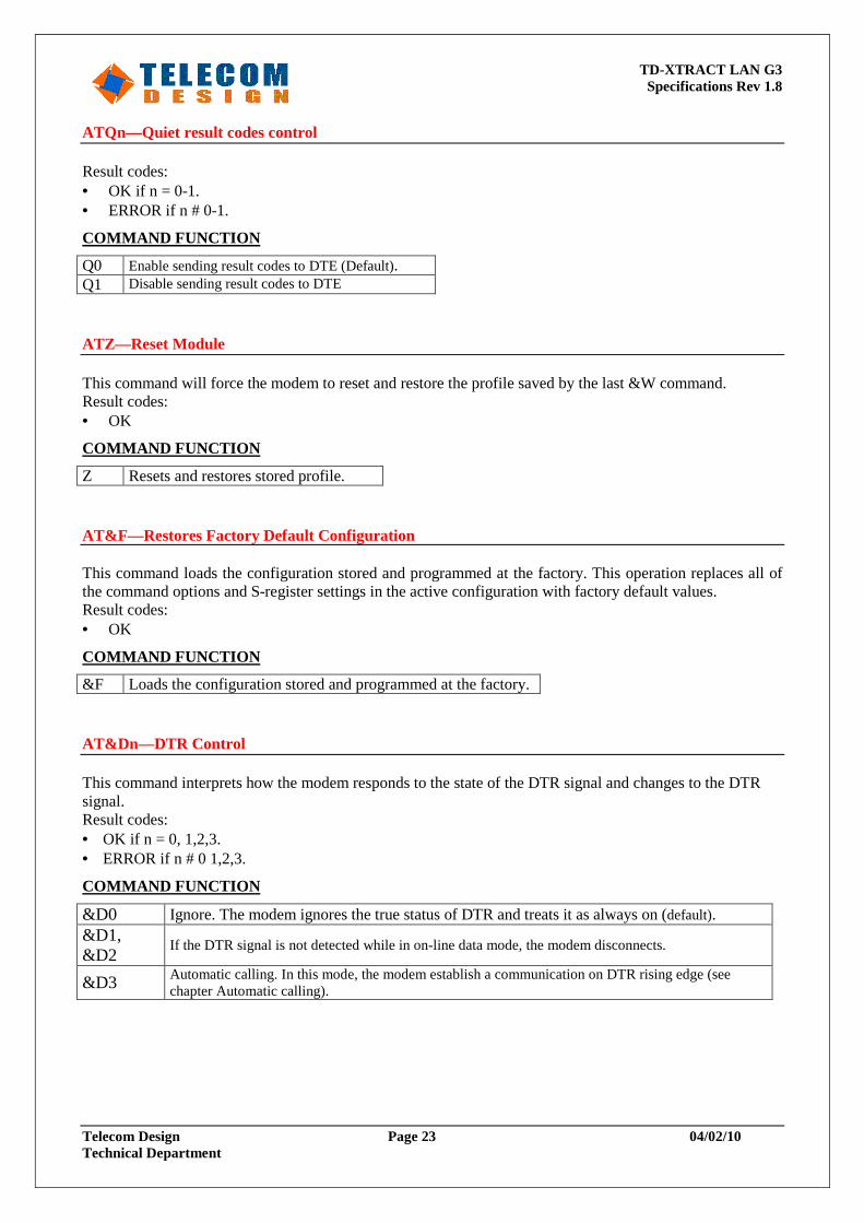
ATQn—Quiet result codes control Result codes: • OK if n = 0-1. • ERROR if n # 0-1.
COMMAND FUNCTION
Q0 Enable sending result codes to DTE (Default). Q1 Disable sending result codes to DTE ATZ—Reset Module This command will force the modem to reset and restore the profile saved by the last &W command. Result codes: • OK
COMMAND FUNCTION
Z Resets and restores stored profile. AT&F—Restores Factory Default Configuration This command loads the configuration stored and programmed at the factory. This operation replaces all of the command options and S-register settings in the active configuration with factory default values. Result codes: • OK
COMMAND FUNCTION
&F Loads the configuration stored and programmed at the factory. AT&Dn—DTR Control This command interprets how the modem responds to the state of the DTR signal and changes to the DTR signal. Result codes: • OK if n = 0, 1,2,3. • ERROR if n # 0 1,2,3.
COMMAND FUNCTION
&D0 Ignore. The modem ignores the true status of DTR and treats it as always on (default). &D1, &D2
If the DTR signal is not detected while in on-line data mode, the modem disconnects.
&D3 Automatic calling. In this mode, the modem establish a communication on DTR rising edge (see chapter Automatic calling).
TD-XTRACT LAN G3 Specifications Rev 1.8
Telecom Design Page 24 04/02/10 Technical Department
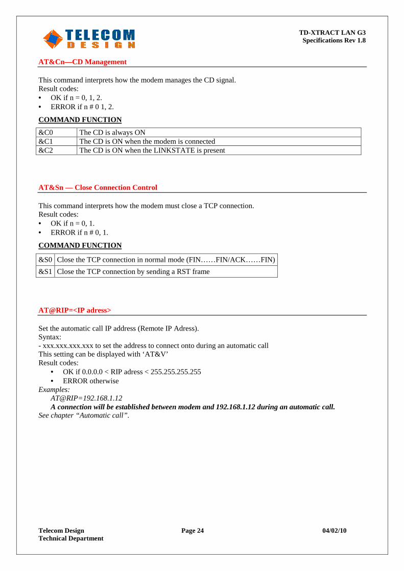
AT&Cn—CD Management This command interprets how the modem manages the CD signal. Result codes: • OK if n = 0, 1, 2. • ERROR if n # 0 1, 2.
COMMAND FUNCTION
&C0 The CD is always ON &C1 The CD is ON when the modem is connected &C2 The CD is ON when the LINKSTATE is present AT&Sn — Close Connection Control This command interprets how the modem must close a TCP connection. Result codes: • OK if n = 0, 1. • ERROR if n # 0, 1.
COMMAND FUNCTION
&S0 Close the TCP connection in normal mode (FIN……FIN/ACK……FIN)
&S1 Close the TCP connection by sending a RST frame
AT@RIP=<IP adress> Set the automatic call IP address (Remote IP Adress). Syntax: - xxx.xxx.xxx.xxx to set the address to connect onto during an automatic call This setting can be displayed with ‘AT&V’ Result codes:
• OK if 0.0.0.0 < RIP adress < 255.255.255.255 • ERROR otherwise
Examples: AT@RIP=192.168.1.12 A connection will be established between modem and 192.168.1.12 during an automatic call.
See chapter “Automatic call”.
TD-XTRACT LAN G3 Specifications Rev 1.8
Telecom Design Page 25 04/02/10 Technical Department
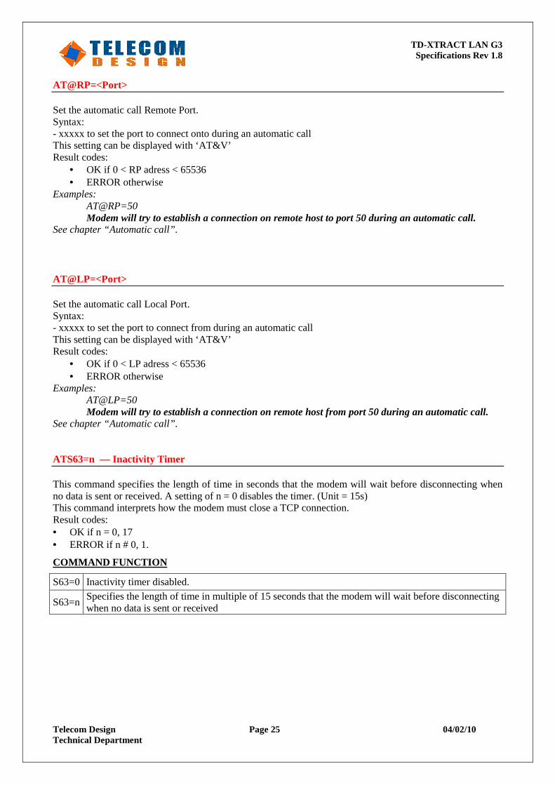
AT@RP=<Port> Set the automatic call Remote Port. Syntax: - xxxxx to set the port to connect onto during an automatic call This setting can be displayed with ‘AT&V’ Result codes:
• OK if 0 < RP adress < 65536 • ERROR otherwise
Examples: AT@RP=50 Modem will try to establish a connection on remote host to port 50 during an automatic call.
See chapter “Automatic call”. AT@LP=<Port> Set the automatic call Local Port. Syntax: - xxxxx to set the port to connect from during an automatic call This setting can be displayed with ‘AT&V’ Result codes:
• OK if 0 < LP adress < 65536 • ERROR otherwise
Examples: AT@LP=50 Modem will try to establish a connection on remote host from port 50 during an automatic call.
See chapter “Automatic call”. ATS63=n — Inactivity Timer This command specifies the length of time in seconds that the modem will wait before disconnecting when no data is sent or received. A setting of n = 0 disables the timer. (Unit = 15s) This command interprets how the modem must close a TCP connection. Result codes: • OK if n = 0, 17 • ERROR if n # 0, 1.
COMMAND FUNCTION
S63=0 Inactivity timer disabled.
S63=n Specifies the length of time in multiple of 15 seconds that the modem will wait before disconnecting when no data is sent or received
TD-XTRACT LAN G3 Specifications Rev 1.8
Telecom Design Page 26 04/02/10 Technical Department
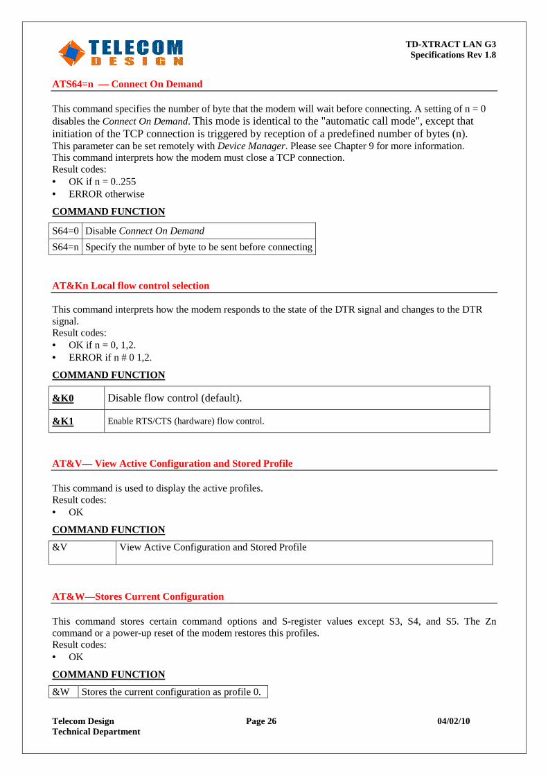
ATS64=n — Connect On Demand This command specifies the number of byte that the modem will wait before connecting. A setting of n = 0 disables the Connect On Demand. This mode is identical to the "automatic call mode", except that initiation of the TCP connection is triggered by reception of a predefined number of bytes (n). This parameter can be set remotely with Device Manager. Please see Chapter 9 for more information. This command interprets how the modem must close a TCP connection. Result codes: • OK if n = 0..255 • ERROR otherwise
COMMAND FUNCTION
S64=0 Disable Connect On Demand
S64=n Specify the number of byte to be sent before connecting
AT&Kn Local flow control selection This command interprets how the modem responds to the state of the DTR signal and changes to the DTR signal. Result codes: • OK if n = 0, 1,2. • ERROR if n # 0 1,2.
COMMAND FUNCTION
&K0 Disable flow control (default).
&K1 Enable RTS/CTS (hardware) flow control.
AT&V— View Active Configuration and Stored Profile This command is used to display the active profiles. Result codes: • OK
COMMAND FUNCTION
&V View Active Configuration and Stored Profile
AT&W —Stores Current Configuration This command stores certain command options and S-register values except S3, S4, and S5. The Zn command or a power-up reset of the modem restores this profiles. Result codes: • OK
COMMAND FUNCTION
&W Stores the current configuration as profile 0.
TD-XTRACT LAN G3 Specifications Rev 1.8
Telecom Design Page 27 04/02/10 Technical Department
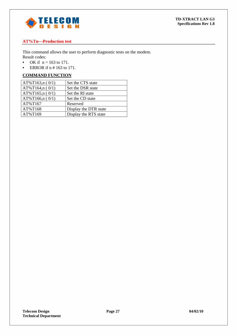
AT%Tn—Production test This command allows the user to perform diagnostic tests on the modem. Result codes: • OK if n = 163 to 171. • ERROR if n # 163 to 171.
COMMAND FUNCTION
AT%T163,n ( 0/1) Set the CTS state AT%T164,n ( 0/1) Set the DSR state AT%T165,n ( 0/1) Set the RI state AT%T166,n ( 0/1) Set the CD state AT%T167 Reserved AT%T168 Display the DTR state AT%T169 Display the RTS state
TD-XTRACT LAN G3 Specifications Rev 1.8
Telecom Design Page 28 04/02/10 Technical Department
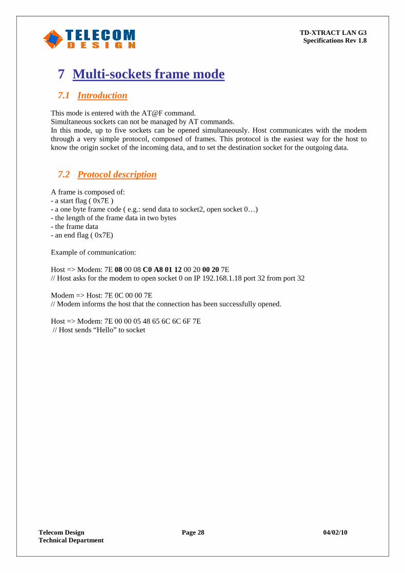
7 Multi-sockets frame mode
7.1 Introduction
This mode is entered with the AT@F command. Simultaneous sockets can not be managed by AT commands. In this mode, up to five sockets can be opened simultaneously. Host communicates with the modem through a very simple protocol, composed of frames. This protocol is the easiest way for the host to know the origin socket of the incoming data, and to set the destination socket for the outgoing data.
7.2 Protocol description
A frame is composed of: - a start flag ( 0x7E ) - a one byte frame code ( e.g.: send data to socket2, open socket 0…) - the length of the frame data in two bytes - the frame data - an end flag ( 0x7E)
Example of communication: Host => Modem: 7E 08 00 08 C0 A8 01 12 00 20 00 20 7E // Host asks for the modem to open socket 0 on IP 192.168.1.18 port 32 from port 32 Modem => Host: 7E 0C 00 00 7E // Modem informs the host that the connection has been successfully opened. Host => Modem: 7E 00 00 05 48 65 6C 6C 6F 7E // Host sends “Hello” to socket
TD-XTRACT LAN G3 Specifications Rev 1.8
Telecom Design Page 29 04/02/10 Technical Department
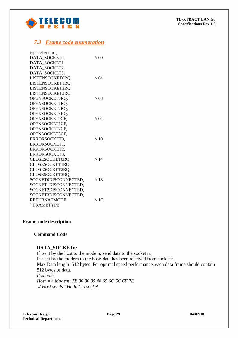
7.3 Frame code enumeration
typedef enum { DATA_SOCKET0, // 00 DATA_SOCKET1, DATA_SOCKET2, DATA_SOCKET3, LISTENSOCKET0RQ, // 04 LISTENSOCKET1RQ, LISTENSOCKET2RQ, LISTENSOCKET3RQ, OPENSOCKET0RQ, // 08 OPENSOCKET1RQ, OPENSOCKET2RQ, OPENSOCKET3RQ, OPENSOCKET0CF, // 0C OPENSOCKET1CF, OPENSOCKET2CF, OPENSOCKET3CF, ERRORSOCKET0, // 10 ERRORSOCKET1, ERRORSOCKET2, ERRORSOCKET3, CLOSESOCKET0RQ, // 14 CLOSESOCKET1RQ, CLOSESOCKET2RQ, CLOSESOCKET3RQ, SOCKET0DISCONNECTED, // 18 SOCKET1DISCONNECTED, SOCKET2DISCONNECTED, SOCKET3DISCONNECTED, RETURNATMODE // 1C } FRAMETYPE;
Frame code description
Command Code
DATA_SOCKETn: If sent by the host to the modem: send data to the socket n. If sent by the modem to the host: data has been received from socket n. Max Data length: 512 bytes. For optimal speed performance, each data frame should contain 512 bytes of data. Example: Host => Modem: 7E 00 00 05 48 65 6C 6C 6F 7E // Host sends “Hello” to socket
TD-XTRACT LAN G3 Specifications Rev 1.8
Telecom Design Page 30 04/02/10 Technical Department
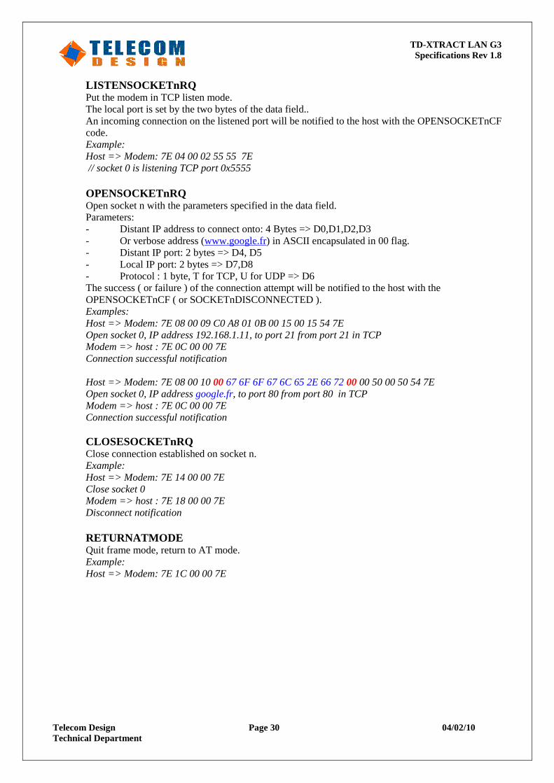
LISTENSOCKETnRQ Put the modem in TCP listen mode. The local port is set by the two bytes of the data field.. An incoming connection on the listened port will be notified to the host with the OPENSOCKETnCF code. Example: Host => Modem: 7E 04 00 02 55 55 7E // socket 0 is listening TCP port 0x5555 OPENSOCKETnRQ Open socket n with the parameters specified in the data field. Parameters: - Distant IP address to connect onto: 4 Bytes => D0,D1,D2,D3 - Or verbose address (www.google.fr) in ASCII encapsulated in 00 flag. - Distant IP port: 2 bytes => D4, D5 - Local IP port: 2 bytes => D7,D8 - Protocol : 1 byte, T for TCP, U for UDP => D6 The success ( or failure ) of the connection attempt will be notified to the host with the OPENSOCKETnCF ( or SOCKETnDISCONNECTED ). Examples: Host => Modem: 7E 08 00 09 C0 A8 01 0B 00 15 00 15 54 7E Open socket 0, IP address 192.168.1.11, to port 21 from port 21 in TCP Modem => host : 7E 0C 00 00 7E Connection successful notification Host => Modem: 7E 08 00 10 00 67 6F 6F 67 6C 65 2E 66 72 00 00 50 00 50 54 7E Open socket 0, IP address google.fr, to port 80 from port 80 in TCP Modem => host : 7E 0C 00 00 7E Connection successful notification CLOSESOCKETnRQ Close connection established on socket n. Example: Host => Modem: 7E 14 00 00 7E Close socket 0 Modem => host : 7E 18 00 00 7E Disconnect notification RETURNATMODE Quit frame mode, return to AT mode. Example: Host => Modem: 7E 1C 00 00 7E
TD-XTRACT LAN G3 Specifications Rev 1.8
Telecom Design Page 31 04/02/10 Technical Department
Notification Codes
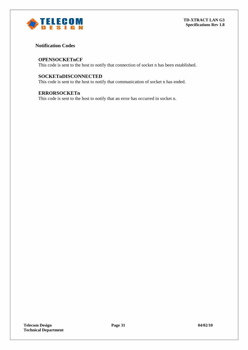
OPENSOCKETnCF This code is sent to the host to notify that connection of socket n has been established. SOCKETnDISCONNECTED This code is sent to the host to notify that communication of socket n has ended. ERRORSOCKETn This code is sent to the host to notify that an error has occurred in socket n.
TD-XTRACT LAN G3 Specifications Rev 1.8
Telecom Design Page 32 04/02/10 Technical Department
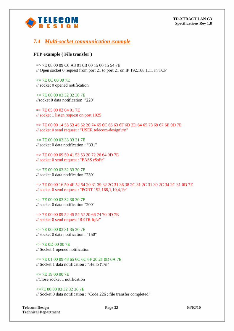
7.4 Multi-socket communication example
FTP example ( File transfer )
=> 7E 08 00 09 C0 A8 01 0B 00 15 00 15 54 7E // Open socket 0 request from port 21 to port 21 on IP 192.168.1.11 in TCP <= 7E 0C 00 00 7E // socket 0 opened notification <= 7E 00 00 03 32 32 30 7E //socket 0 data notification "220" => 7E 05 00 02 04 01 7E // socket 1 listen request on port 1025 => 7E 00 00 14 55 53 45 52 20 74 65 6C 65 63 6F 6D 2D 64 65 73 69 67 6E 0D 7E // socket 0 send request : "USER telecom-design\r\n" <= 7E 00 00 03 33 33 31 7E // socket 0 data notification : “331" => 7E 00 00 09 50 41 53 53 20 72 26 64 0D 7E // socket 0 send request : "PASS r&d\r" <= 7E 00 00 03 32 33 30 7E // socket 0 data notification "230" => 7E 00 00 16 50 4F 52 54 20 31 39 32 2C 31 36 38 2C 31 2C 31 30 2C 34 2C 31 0D 7E // socket 0 send request : "PORT 192,168,1,10,4,1\r" <= 7E 00 00 03 32 30 30 7E // socket 0 data notification "200" => 7E 00 00 09 52 45 54 52 20 66 74 70 0D 7E // socket 0 send request "RETR ftp\r" <= 7E 00 00 03 31 35 30 7E // socket 0 data notification : "150" <= 7E 0D 00 00 7E // Socket 1 opened notification <= 7E 01 00 09 48 65 6C 6C 6F 20 21 0D 0A 7E // Socket 1 data notification : "Hello !\r\n" <= 7E 19 00 00 7E //Close socket 1 notification <=7E 00 00 03 32 32 36 7E // Socket 0 data notification : "Code 226 : file transfer completed"
TD-XTRACT LAN G3 Specifications Rev 1.8
Telecom Design Page 33 04/02/10 Technical Department
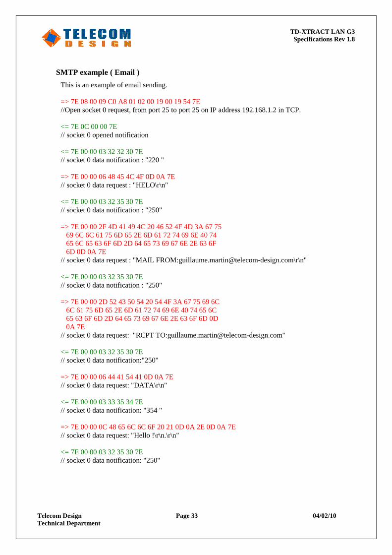
SMTP example ( Email )
This is an example of email sending. => 7E 08 00 09 C0 A8 01 02 00 19 00 19 54 7E //Open socket 0 request, from port 25 to port 25 on IP address 192.168.1.2 in TCP. <= 7E 0C 00 00 7E // socket 0 opened notification <= 7E 00 00 03 32 32 30 7E // socket 0 data notification : "220 " => 7E 00 00 06 48 45 4C 4F 0D 0A 7E // socket 0 data request : "HELO\r\n" <= 7E 00 00 03 32 35 30 7E // socket 0 data notification : "250" => 7E 00 00 2F 4D 41 49 4C 20 46 52 4F 4D 3A 67 75 69 6C 6C 61 75 6D 65 2E 6D 61 72 74 69 6E 40 74 65 6C 65 63 6F 6D 2D 64 65 73 69 67 6E 2E 63 6F 6D 0D 0A 7E // socket 0 data request : "MAIL FROM:[email protected]\r\n" <= 7E 00 00 03 32 35 30 7E // socket 0 data notification : "250" => 7E 00 00 2D 52 43 50 54 20 54 4F 3A 67 75 69 6C 6C 61 75 6D 65 2E 6D 61 72 74 69 6E 40 74 65 6C 65 63 6F 6D 2D 64 65 73 69 67 6E 2E 63 6F 6D 0D 0A 7E // socket 0 data request: "RCPT TO:[email protected]" <= 7E 00 00 03 32 35 30 7E // socket 0 data notification:"250" => 7E 00 00 06 44 41 54 41 0D 0A 7E // socket 0 data request: "DATA\r\n" <= 7E 00 00 03 33 35 34 7E // socket 0 data notification: "354 " => 7E 00 00 0C 48 65 6C 6C 6F 20 21 0D 0A 2E 0D 0A 7E // socket 0 data request: "Hello !\r\n.\r\n" <= 7E 00 00 03 32 35 30 7E // socket 0 data notification: "250"
TD-XTRACT LAN G3 Specifications Rev 1.8
Telecom Design Page 34 04/02/10 Technical Department
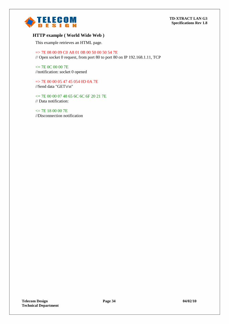
HTTP example ( World Wide Web )
This example retrieves an HTML page. => 7E 08 00 09 C0 A8 01 0B 00 50 00 50 54 7E // Open socket 0 request, from port 80 to port 80 on IP 192.168.1.11, TCP <= 7E 0C 00 00 7E //notification: socket 0 opened => 7E 00 00 05 47 45 054 0D 0A 7E //Send data "GET\r\n" <= 7E 00 00 07 48 65 6C 6C 6F 20 21 7E // Data notification: <= 7E 18 00 00 7E //Disconnection notification
TD-XTRACT LAN G3 Specifications Rev 1.8
Telecom Design Page 35 04/02/10 Technical Department
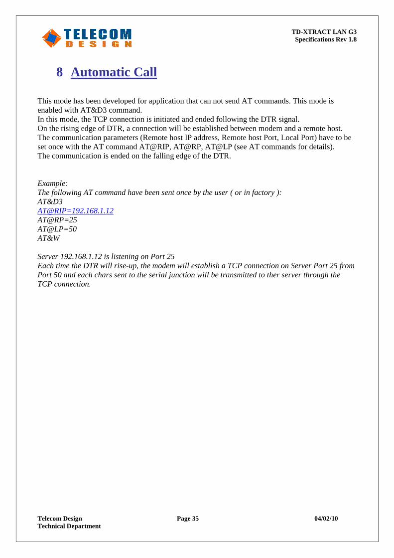
8 Automatic Call This mode has been developed for application that can not send AT commands. This mode is enabled with AT&D3 command. In this mode, the TCP connection is initiated and ended following the DTR signal. On the rising edge of DTR, a connection will be established between modem and a remote host. The communication parameters (Remote host IP address, Remote host Port, Local Port) have to be set once with the AT command AT@RIP, AT@RP, AT@LP (see AT commands for details). The communication is ended on the falling edge of the DTR. Example: The following AT command have been sent once by the user ( or in factory ): AT&D3 AT@RIP=192.168.1.12 AT@RP=25 AT@LP=50 AT&W Server 192.168.1.12 is listening on Port 25 Each time the DTR will rise-up, the modem will establish a TCP connection on Server Port 25 from Port 50 and each chars sent to the serial junction will be transmitted to ther server through the TCP connection.
TD-XTRACT LAN G3 Specifications Rev 1.8
Telecom Design Page 36 04/02/10 Technical Department
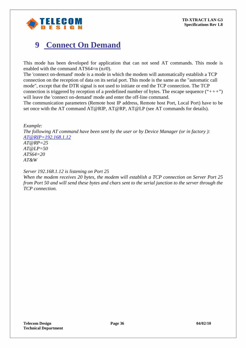
9 Connect On Demand This mode has been developed for application that can not send AT commands. This mode is enabled with the command ATS64=n (n≠0). The 'connect on-demand' mode is a mode in which the modem will automatically establish a TCP connection on the reception of data on its serial port. This mode is the same as the "automatic call mode", except that the DTR signal is not used to initiate or end the TCP connection. The TCP connection is triggered by reception of a predefined number of bytes. The escape sequence (“+++ ”) will leave the 'connect on-demand' mode and enter the off-line command. The communication parameters (Remote host IP address, Remote host Port, Local Port) have to be set once with the AT command AT@RIP, AT@RP, AT@LP (see AT commands for details). Example: The following AT command have been sent by the user or by Device Manager (or in factory ): AT@RIP=192.168.1.12 AT@RP=25 AT@LP=50 ATS64=20 AT&W Server 192.168.1.12 is listening on Port 25 When the modem receives 20 bytes, the modem will establish a TCP connection on Server Port 25 from Port 50 and will send these bytes and chars sent to the serial junction to the server through the TCP connection.
TD-XTRACT LAN G3 Specifications Rev 1.8
Telecom Design Page 37 04/02/10 Technical Department
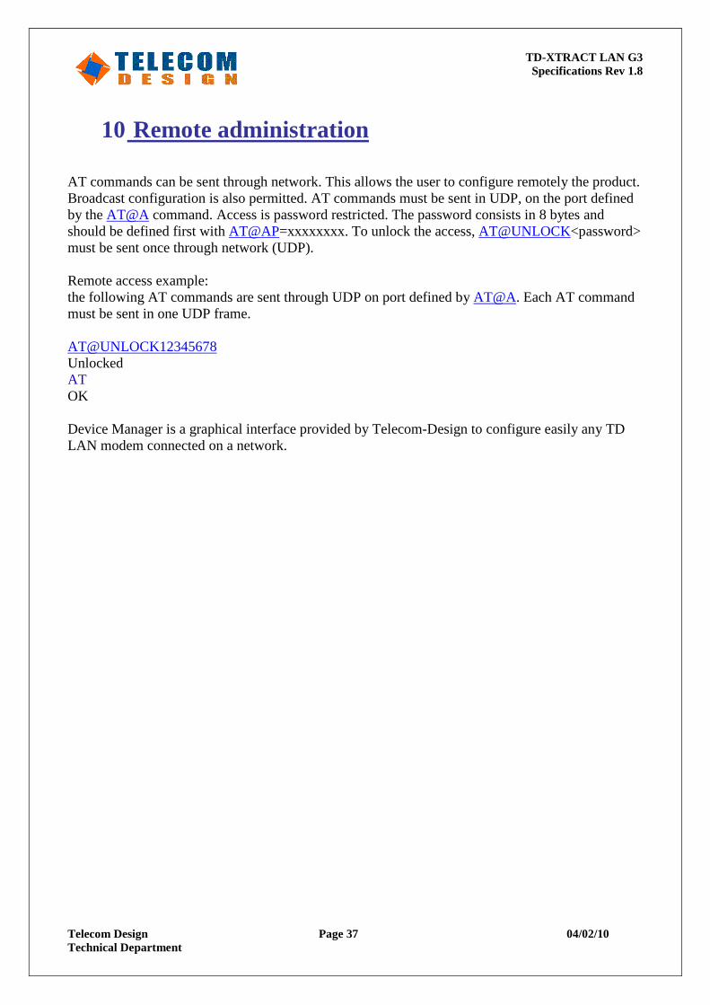
10 Remote administration AT commands can be sent through network. This allows the user to configure remotely the product. Broadcast configuration is also permitted. AT commands must be sent in UDP, on the port defined by the AT@A command. Access is password restricted. The password consists in 8 bytes and should be defined first with AT@AP=xxxxxxxx. To unlock the access, AT@UNLOCK<password> must be sent once through network (UDP). Remote access example: the following AT commands are sent through UDP on port defined by AT@A. Each AT command must be sent in one UDP frame. AT@UNLOCK12345678 Unlocked AT OK Device Manager is a graphical interface provided by Telecom-Design to configure easily any TD LAN modem connected on a network.
TD-XTRACT LAN G3 Specifications Rev 1.8
Telecom Design Page 38 04/02/10 Technical Department
NOTES
Notice: The products and services of Telecom Design described herein are sold subject to TD's standard terms and conditions of sale. Customers are advised to obtain the most current and complete information about TD products and services before placing orders. TD assumes no liability for applications assistance, customer's applications or product designs, software performance, or infringement of patents. The publication of information regarding any other company's products or services does not constitute TD's approval, warranty or endorsement thereof.