Embed Size (px)
Citation preview
TD-VG5612 300Mbps Wireless N VoIP VDSL/ADSL Modem Router
Rev: 1.0.0
1910011437

COPYRIGHT & TRADEMARKS Specifications are subject to change without notice. is a registered trademark of TP-LINK TECHNOLOGIES CO., LTD. Other brands and product names are trademarks or registered trademarks of their respective holders.
No part of the specifications may be reproduced in any form or by any means or used to make any derivative such as translation, transformation, or adaptation without permission from TP-LINK TECHNOLOGIES CO., LTD. Copyright © 2015 TP-LINK TECHNOLOGIES CO., LTD. All rights reserved.
http://www.tp-link.com
FCC STATEMENT
This equipment has been tested and found to comply with the limits for a Class B digital device, pursuant to part 15 of the FCC Rules. These limits are designed to provide reasonable protection against harmful interference in a residential installation. This equipment generates, uses and can radiate radio frequency energy and, if not installed and used in accordance with the instructions, may cause harmful interference to radio communications. However, there is no guarantee that interference will not occur in a particular installation. If this equipment does cause harmful interference to radio or television reception, which can be determined by turning the equipment off and on, the user is encouraged to try to correct the interference by one or more of the following measures:
• Reorient or relocate the receiving antenna.
• Increase the separation between the equipment and receiver.
• Connect the equipment into an outlet on a circuit different from that to which the receiver is connected.
• Consult the dealer or an experienced radio/ TV technician for help.
This device complies with part 15 of the FCC Rules. Operation is subject to the following two conditions:
1) This device may not cause harmful interference.
2) This device must accept any interference received, including interference that may cause undesired operation.
Any changes or modifications not expressly approved by the party responsible for compliance could void the user’s authority to operate the equipment.
Note: The manufacturer is not responsible for any radio or tv interference caused by unauthorized modifications to this equipment. Such modifications could void the user’s authority to operate the equipment.
FCC RF Radiation Exposure Statement This equipment complies with FCC RF radiation exposure limits set forth for an uncontrolled environment. This device and its antenna must not be co-located or operating in conjunction with any other antenna or transmitter.
“To comply with FCC RF exposure compliance requirements, this grant is applicable to only Mobile Configurations. The antennas used for this transmitter must be installed to provide a separation distance of at least 20 cm from all persons and must not be co-located or operating in conjunction with any other antenna or transmitter.”
CE Mark Warning
This is a class B product. In a domestic environment, this product may cause radio interference, in which case the user may be required to take adequate measures.
RF Exposure Information This device meets the EU requirements (1999/519/EC) on the limitation of exposure of the general public to electromagnetic fields by way of health protection.
The device complies with RF specifications when the device used at 20 cm from your body.
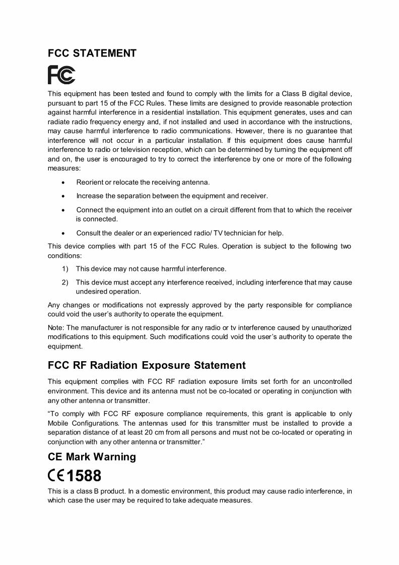
National Restrictions This device is intended for home and office use in all EU countries (and other countries following the EU directive 1999/5/EC) without any limitation except for the countries mentioned below:
Country Restriction Reason/remark
Belarus Not implemented
Norway Implemented This subsection does not apply for the geographical area within a radius of 20 km from the centre of Ny-Ålesund on Svalbard.
Italy Implemented The public use is subject to general authorisation by the respective service provider.
Russian Federation
Limited implementation
1. SRD with FHSS modulation 1.1. Maximum 2.5 mW e.i.r.p. 1.2. Maximum 100 mW e.i.r.p. Permitted for use SRD for outdoor applications without restriction on installation height only for purposes of gathering telemetry information for automated monitoring and resources accounting systems. Permitted to use SRD for other purposes for outdoor applications only when the installation height is not exceeding 10 m above the ground surface. 1.3.Maximum 100 mW e.i.r.p. Indoor applications. 2. SRD with DSSS and other than FHSS wideband modulation 2.1. Maximum mean e.i.r.p. density is 2 mW/MHz. Maximum 100 mW e.i.r.p. 2.2. Maximum mean e.i.r.p. density is 20 mW/MHz. Maximum 100 mW e.i.r.p. It is permitted to use SRD for outdoor applications only for purposes of gathering telemetry information for automated monitoring and resources accounting systems or security systems. 2.3. Maximum mean e.i.r.p. density is 10 mW/MHz. Maximum 100 mW e.i.r.p. Indoor applications.
Ukraine Limited implementation
e.i.r.p. ≤100 mW with built-in antenna with amplification factor up to 6 dBi.
ATTENTION: Due to EU law, the country settings must be identical to the country where the device is operating (important due to non-harmonised frequencies in the EU).
Canadian Compliance Statement This device complies with Industry Canada license-exempt RSSs. Operation is subject to the following two conditions: 1) This device may not cause interference, and 2) This device must accept any interference, including interference that may cause undesired
operation of the device. Le présent appareil est conforme aux CNR d’Industrie Canada applicables aux appareils radio exempts de licence. L’exploitation est autorisée aux deux conditions suivantes :
1) l’appareil ne doit pas produire de brouillage; 2) l’utilisateur de l’appareil doit accepter tout brouillage radioélectrique subi, meme si le
brouillage est susceptible d’en compromettre le fonctionnement.
Radiation Exposure Statement: This equipment complies with IC radiation exposure limits set forth for an uncontrolled environment. This equipment should be installed and operated with minimum distance 20cm between the radiator & your body.
Déclaration d'exposition aux radiations: Cet équipement est conforme aux limites d'exposition aux rayonnements IC établies pour un environnement non contrôlé. Cet équipement doit être installé et utilisé avec un minimum de 20 cm de distance entre la source de rayonnement et votre corps.
Industry Canada Statement CAN ICES-3 (B)/NMB-3(B)
NCC Notice & BSMI Notice 注意! 依據 低功率電波輻射性電機管理辦法 第十二條 經型式認證合格之低功率射頻電機,非經許可,公司、商號或使用者均不得擅自變更頻率、
加大功率或變更原設計之特性或功能。 第十四條 低功率射頻電機之使用不得影響飛航安全及干擾合法通行;經發現有干擾現象
時,應立即停用,並改善至無干擾時方得繼續使用。前項合法通信,指依電信規定作業之無線電信。
低功率射頻電機需忍受合法通信或工業、科學以及醫療用電波輻射性電機設備之干擾。 減少電磁波影響,請妥適使用。
安全諮詢及注意事項 請使用原裝電源供應器或只能按照本產品注明的電源類型使用本產品。 清潔本產品之前請先拔掉電源線。請勿使用液體、噴霧清潔劑或濕布進行清潔。 注意防潮,請勿將水或其他液體潑灑到本產品上。 插槽與開口供通風使用,以確保本產品的操作可靠並防止過熱,請勿堵塞或覆蓋開口。
請勿將本產品置放於靠近熱源的地方。除非有正常的通風,否則不可放在密閉位置中。 請不要私自打開機殼,不要嘗試自行維修本產品,請由授權的專業人士進行此項工作。
Korea Warning Statements 당해 무선설비는 운용중 전파혼신 가능성이 있음.
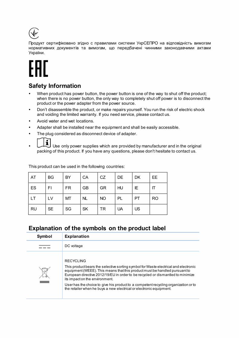
Продукт сертифіковано згідно с правилами системи УкрСЕПРО на відповідність вимогам нормативних документів та вимогам, що передбачені чинними законодавчими актами України.
Safety Information When product has power button, the power button is one of the way to shut off the product;
when there is no power button, the only way to completely shut off power is to disconnect the product or the power adapter from the power source.
Don’t disassemble the product, or make repairs yourself. You run the risk of electric shock and voiding the limited warranty. If you need service, please contact us.
Avoid water and wet locations. Adapter shall be installed near the equipment and shall be easily accessible. The plug considered as disconnect device of adapter.
Use only power supplies which are provided by manufacturer and in the original packing of this product. If you have any questions, please don't hesitate to contact us.
This product can be used in the following countries:
Explanation of the symbols on the product label
Symbol Explanation
DC voltage
RECYCLING This product bears the selective sorting symbol for Waste electrical and electronic equipment (WEEE). This means that this product must be handled pursuant to European directive 2012/19/EU in order to be recycled or dismantled to minimize its impact on the environment. User has the choice to give his product to a competent recycling organization or to the retailer when he buys a new electrical or electronic equipment.
AT BG BY CA CZ DE DK EE
ES FI FR GB GR HU IE IT
LT LV MT NL NO PL PT RO
RU SE SG SK TR UA US
TP-LINK TECHNOLOGIES CO., LTD
TP-LINK TECHNOLOGIES CO., LTD Building 24 (floors 1, 3, 4, 5), and 28 (floors 1-4) Central Science and Technology Park,
Shennan Rd, Nanshan, Shenzhen, China
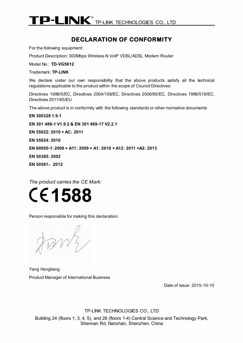
DECLARATION OF CONFORMITY For the following equipment:
Product Description: 300Mbps Wireless N VoIP VDSL/ADSL Modem Router
Model No.: TD-VG5612
Trademark: TP-LINK
We declare under our own responsibility that the above products satisfy all the technical regulations applicable to the product within the scope of Council Directives:
Directives 1999/5/EC, Directives 2004/108/EC, Directives 2006/95/EC, Directives 1999/519/EC, Directives 2011/65/EU
The above product is in conformity with the following standards or other normative documents
EN 300328 1.9.1
EN 301 489-1 V1.9.2 & EN 301 489-17 V2.2.1
EN 55022: 2010 + AC: 2011
EN 55024: 2010
EN 60950-1: 2006 + A11: 2009 + A1: 2010 + A12: 2011 +A2: 2013
EN 50385: 2002
EN 50581:2012
The product carries the CE Mark:
Person responsible for making this declaration:
Yang Hongliang
Product Manager of International Business
Date of issue: 2015-10-10
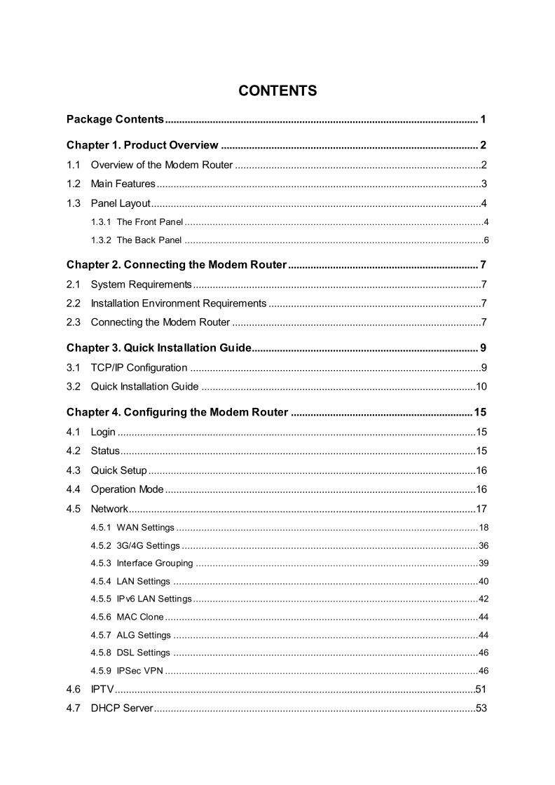
CONTENTS
Package Contents ................................................................................................................ 1
Chapter 1. Product Overview ............................................................................................ 2
1.1 Overview of the Modem Router ........................................................................................2
1.2 Main Features....................................................................................................................3
1.3 Panel Layout......................................................................................................................4
1.3.1 The Front Panel ...........................................................................................................4
1.3.2 The Back Panel ...........................................................................................................6
Chapter 2. Connecting the Modem Router .................................................................... 7
2.1 System Requirements .......................................................................................................7
2.2 Installation Environment Requirements ............................................................................7
2.3 Connecting the Modem Router .........................................................................................7
Chapter 3. Quick Installation Guide................................................................................. 9
3.1 TCP/IP Configuration ........................................................................................................9
3.2 Quick Installation Guide ..................................................................................................10
Chapter 4. Configuring the Modem Router ................................................................. 15
4.1 Login ................................................................................................................................15
4.2 Status...............................................................................................................................15
4.3 Quick Setup .....................................................................................................................16
4.4 Operation Mode ...............................................................................................................16
4.5 Network............................................................................................................................17
4.5.1 WAN Settings ............................................................................................................ 18
4.5.2 3G/4G Settings .......................................................................................................... 36
4.5.3 Interface Grouping ..................................................................................................... 39
4.5.4 LAN Settings ............................................................................................................. 40
4.5.5 IPv6 LAN Settings ...................................................................................................... 42
4.5.6 MAC Clone ................................................................................................................ 44
4.5.7 ALG Settings ............................................................................................................. 44
4.5.8 DSL Settings ............................................................................................................. 46
4.5.9 IPSec VPN ................................................................................................................ 46
4.6 IPTV .................................................................................................................................51
4.7 DHCP Server ...................................................................................................................53
4.7.1 DHCP Settings .......................................................................................................... 53
4.7.2 Clients List................................................................................................................. 55
4.7.3 Address Reservation .................................................................................................. 55
4.7.4 Conditional Pool......................................................................................................... 56
4.8 Wireless ...........................................................................................................................57
4.8.1 Basic Settings............................................................................................................ 57
4.8.2 WPS Settings ............................................................................................................ 59
4.8.3 Wireless Security ....................................................................................................... 62
4.8.4 Wireless Schedule ..................................................................................................... 64
4.8.5 Wireless MAC Filtering ............................................................................................... 65
4.8.6 Wireless Advanced .................................................................................................... 67
4.8.7 Wireless Status.......................................................................................................... 68
4.9 Guest Network .................................................................................................................69
4.9.1 Basic Settings............................................................................................................ 69
4.9.2 Guest Network Status ................................................................................................ 70
4.10 Voice ................................................................................................................................70
4.10.1 SIP Account ............................................................................................................. 71
4.10.2 Dial Plan .................................................................................................................. 73
4.10.3 Warmline.................................................................................................................. 75
4.10.4 Phone Setup ............................................................................................................ 75
4.10.5 Call Blocks ............................................................................................................... 76
4.10.6 Call Forward............................................................................................................. 78
4.10.7 Advanced Setup ....................................................................................................... 79
4.10.8 Speed Dial ............................................................................................................... 80
4.10.9 Call Log ................................................................................................................... 81
4.10.10 USB Voice Mail ..................................................................................................... 82
4.10.11 Feature Code Setting ............................................................................................ 84
4.11 USB Settings ...................................................................................................................84
4.11.1 USB Mass Storage ................................................................................................... 85
4.11.2 User Accounts .......................................................................................................... 85
4.11.3 Storage Sharing........................................................................................................ 86
4.11.4 FTP Server............................................................................................................... 88
4.11.5 Media Server ............................................................................................................ 90
4.12 Route Settings .................................................................................................................91
4.12.1 Default Gateway ....................................................................................................... 91
4.12.2 Static Route ............................................................................................................. 92
4.12.3 RIP Settings ............................................................................................................. 93
4.13 IPv6 Route Settings.........................................................................................................93
4.13.1 IPv6 Default Gateway ............................................................................................... 93
4.13.2 IPv6 Static Route ...................................................................................................... 94
4.14 Forwarding .......................................................................................................................95
4.14.1 Virtual Servers .......................................................................................................... 95
4.14.2 Port Triggering.......................................................................................................... 97
4.14.3 DMZ ........................................................................................................................ 98
4.14.4 UPnP ....................................................................................................................... 99
4.15 Parent Control ...............................................................................................................100
4.16 Firewall ..........................................................................................................................101
4.16.1 Rule ....................................................................................................................... 101
4.16.2 LAN Host ............................................................................................................... 102
4.16.3 WAN Host .............................................................................................................. 103
4.16.4 Schedule................................................................................................................ 104
4.17 IPv6 Firewall ..................................................................................................................105
4.17.1 IPv6 Rule ............................................................................................................... 106
4.17.2 IPv6 LAN Host ........................................................................................................ 107
4.17.3 IPv6 WAN Host ...................................................................................................... 108
4.17.4 IPv6 Schedule ........................................................................................................ 108
4.18 IPv6 Tunnel....................................................................................................................109
4.19 Bandwidth Control .........................................................................................................112
4.20 IP & MAC Binding ..........................................................................................................113
4.20.1 Binding Settings...................................................................................................... 113
4.20.2 ARP List................................................................................................................. 114
4.21 Dynamic DNS ................................................................................................................115
4.22 Diagnostic ......................................................................................................................115
4.23 System Tools .................................................................................................................116
4.23.1 System Log ............................................................................................................ 116
4.23.2 Time Settings ......................................................................................................... 117
4.23.3 Manage Control ...................................................................................................... 118
4.23.4 CWMP Settings ...................................................................................................... 119
4.23.5 SNMP Settings ....................................................................................................... 120
4.23.6 Backup & Restore................................................................................................... 121
4.23.7 Factory Defaults ..................................................................................................... 121
4.23.8 Firmware Upgrade .................................................................................................. 122

4.23.9 Reboot ................................................................................................................... 123
4.23.10 Statistics ............................................................................................................. 123
4.24 Logout ............................................................................................................................125
Appendix A: Specifications ........................................................................................... 126
Appendix B: Troubleshooting....................................................................................... 127
Appendix C: Telephony Features ................................................................................ 133
TD-VG5612 300Mbps Wireless N VoIP VDSL/ADSL Modem Router User Guide
1
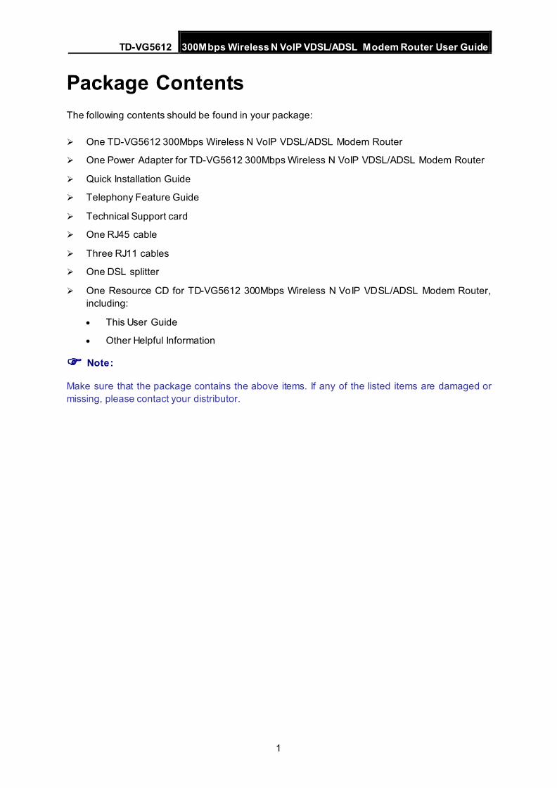
Package Contents The following contents should be found in your package:
One TD-VG5612 300Mbps Wireless N VoIP VDSL/ADSL Modem Router
One Power Adapter for TD-VG5612 300Mbps Wireless N VoIP VDSL/ADSL Modem Router
Quick Installation Guide
Telephony Feature Guide
Technical Support card
One RJ45 cable
Three RJ11 cables
One DSL splitter
One Resource CD for TD-VG5612 300Mbps Wireless N VoIP VDSL/ADSL Modem Router, including:
• This User Guide
• Other Helpful Information
Note:
Make sure that the package contains the above items. If any of the listed items are damaged or missing, please contact your distributor.
TD-VG5612 300Mbps Wireless N VoIP VDSL/ADSL Modem Router User Guide
2
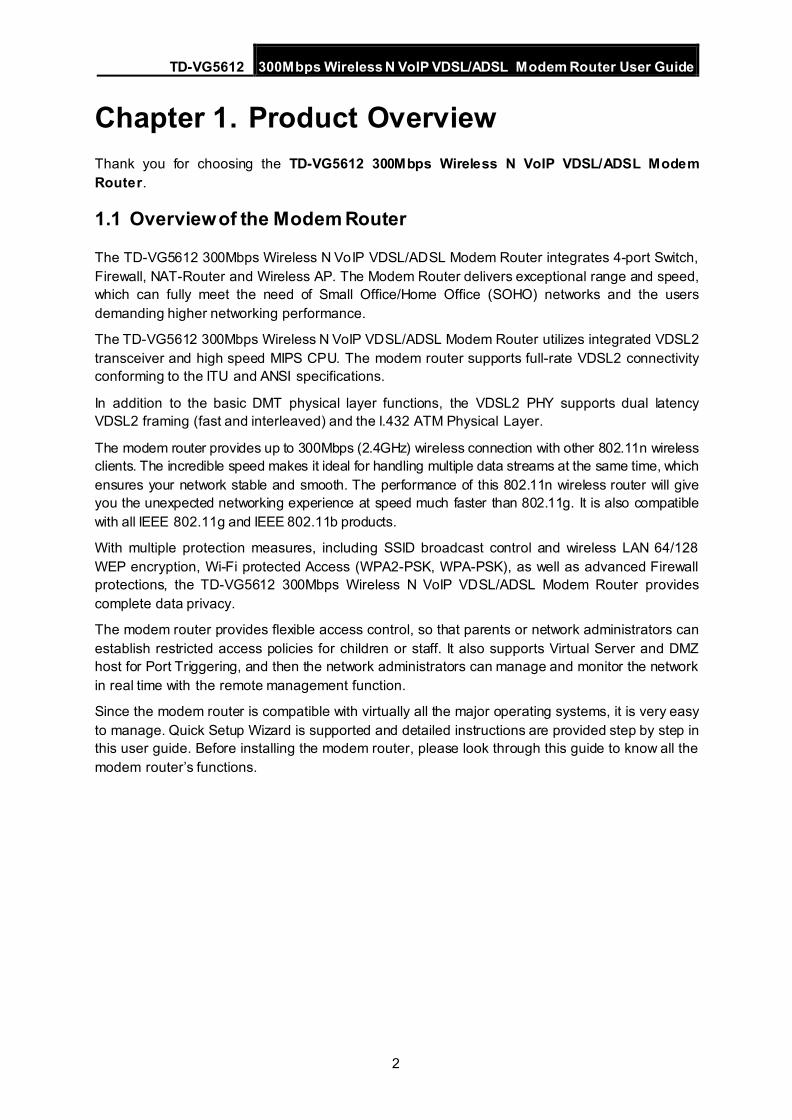
Chapter 1. Product Overview Thank you for choosing the TD-VG5612 300Mbps Wireless N VoIP VDSL/ADSL Modem Router.
1.1 Overview of the Modem Router
The TD-VG5612 300Mbps Wireless N VoIP VDSL/ADSL Modem Router integrates 4-port Switch, Firewall, NAT-Router and Wireless AP. The Modem Router delivers exceptional range and speed, which can fully meet the need of Small Office/Home Office (SOHO) networks and the users demanding higher networking performance.
The TD-VG5612 300Mbps Wireless N VoIP VDSL/ADSL Modem Router utilizes integrated VDSL2 transceiver and high speed MIPS CPU. The modem router supports full-rate VDSL2 connectivity conforming to the ITU and ANSI specifications.
In addition to the basic DMT physical layer functions, the VDSL2 PHY supports dual latency VDSL2 framing (fast and interleaved) and the I.432 ATM Physical Layer.
The modem router provides up to 300Mbps (2.4GHz) wireless connection with other 802.11n wireless clients. The incredible speed makes it ideal for handling multiple data streams at the same time, which ensures your network stable and smooth. The performance of this 802.11n wireless router will give you the unexpected networking experience at speed much faster than 802.11g. It is also compatible with all IEEE 802.11g and IEEE 802.11b products.
With multiple protection measures, including SSID broadcast control and wireless LAN 64/128 WEP encryption, Wi-Fi protected Access (WPA2-PSK, WPA-PSK), as well as advanced Firewall protections, the TD-VG5612 300Mbps Wireless N VoIP VDSL/ADSL Modem Router provides complete data privacy.
The modem router provides flexible access control, so that parents or network administrators can establish restricted access policies for children or staff. It also supports Virtual Server and DMZ host for Port Triggering, and then the network administrators can manage and monitor the network in real time with the remote management function.
Since the modem router is compatible with virtually all the major operating systems, it is very easy to manage. Quick Setup Wizard is supported and detailed instructions are provided step by step in this user guide. Before installing the modem router, please look through this guide to know all the modem router’s functions.
TD-VG5612 300Mbps Wireless N VoIP VDSL/ADSL Modem Router User Guide
3
1.2 Main Features
Complies with IEEE 802.11n to provide a wireless data rate of up to 300Mbps (2.4GHz).
Four 10/100Mbps Auto-Negotiation RJ45 LAN ports (Auto MDI/MDIX), three RJ11 ports (one DSL port & two PHONE ports).
Provides external splitter.
Adopts Advanced DMT modulation and demodulation technology.
Supports bridge mode and Router function.
Multi-user sharing a high-speed Internet connection.
Downstream data rates up to 100Mbps, upstream data rates up to 60Mbps.
Supports long transfers, the max line length can reach to 6.5Km.
Supporting VoIP service.
Various call features such as Multi-accounts, call waiting, call holding, call forwarding, 3-way conference calls and USB voice mail.
Supports remote configuration and management through SNMP and CWMP.
Supports PPPoE, it allows connecting the internet on demand and disconnecting from the
Internet when idle.
Provides reliable ESD and surge-protect function with quick response semi-conductive surge protection circuit.
High speed and asymmetrical data transmit mode, provides safe and exclusive bandwidth.
Compatible with all mainstreams DSLAM (CO).
Provides integrated access of internet and route function which face to SOHO user.
Real-time Configuration and device monitoring.
Supports Multiple PVC (Permanent Virtual Circuit).
Built-in DHCP server.
Built-in firewall, supporting IP/MAC filter and URL filter.
Supports Virtual Server, DMZ host and Port Triggering.
Supports Dynamic DNS, UPnP and Static Routing.
Supports system log and flow Statistics.
Supports firmware upgrade and Web-Management page.
Provides WPA-PSK/WPA2-PSK data security, TKIP/AES encryption security.
Provides 64/128-bit WEP encryption security and wireless LAN ACL (Access Control List).
Supports USB Storage Sharing, FTP Server, Media Server.
Supports Ethernet WAN (EWAN).
Supports Bandwidth Control.
Supports ADSL and VDSL.
TD-VG5612 300Mbps Wireless N VoIP VDSL/ADSL Modem Router User Guide
4
1.3 Panel Layout
1.3.1 The Front Panel
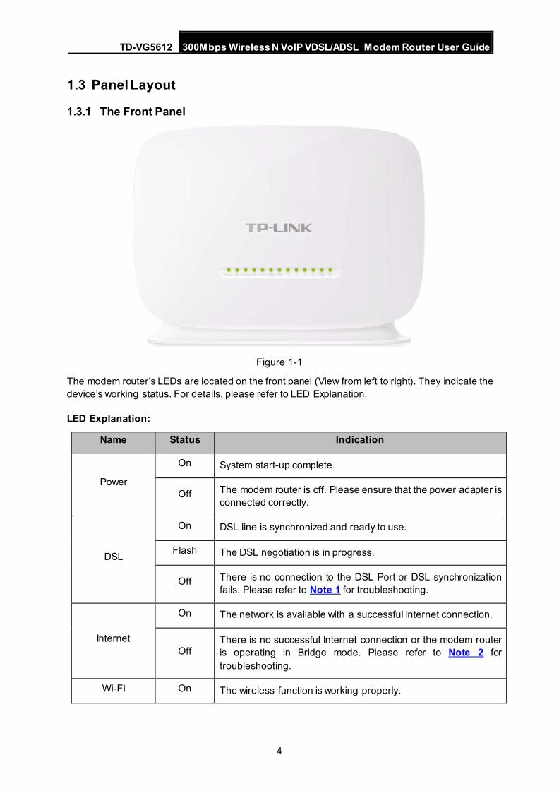
Figure 1-1
The modem router’s LEDs are located on the front panel (View from left to right). They indicate the device’s working status. For details, please refer to LED Explanation.
LED Explanation:
Name Status Indication
Power
On System start-up complete.
Off The modem router is off. Please ensure that the power adapter is connected correctly.
DSL
On DSL line is synchronized and ready to use.
Flash The DSL negotiation is in progress.
Off There is no connection to the DSL Port or DSL synchronization fails. Please refer to Note 1 for troubleshooting.
Internet
On The network is available with a successful Internet connection.
Off There is no successful Internet connection or the modem router is operating in Bridge mode. Please refer to Note 2 for troubleshooting.
Wi-Fi On The wireless function is working properly.
TD-VG5612 300Mbps Wireless N VoIP VDSL/ADSL Modem Router User Guide
5
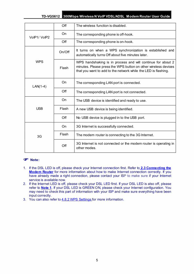
Off The wireless function is disabled.
VoIP1/ VoIP2 On The corresponding phone is off-hook.
Off The corresponding phone is on-hook.
WPS
On/Off It turns on when a WPS synchronization is established and automatically turns Off about five minutes later.
Flash WPS handshaking is in process and will continue for about 2 minutes. Please press the WPS button on other wireless devices that you want to add to the network while the LED is flashing.
LAN(1-4) On The corresponding LAN port is connected.
Off The corresponding LAN port is not connected.
USB
On The USB device is identified and ready to use.
Flash A new USB device is being identified.
Off No USB device is plugged in to the USB port.
3G
On 3G Internet is successfully connected.
Flash The modem router is connecting to the 3G Internet.
Off 3G Internet is not connected or the modem router is operating in other modes.
Note:
1. If the DSL LED is off, please check your Internet connection first. Refer to 2.3 Connecting the Modem Router for more information about how to make Internet connection correctly. If you have already made a right connection, please contact your ISP to make sure if your Internet service is available now.
2. If the Internet LED is off, please check your DSL LED first. If your DSL LED is also off, please refer to Note 1. If your DSL LED is GREEN ON, please check your Internet configuration. You may need to check this part of information with your ISP and make sure everything have been input correctly.
3. You can also refer to 4.8.2 WPS Settings for more information.
TD-VG5612 300Mbps Wireless N VoIP VDSL/ADSL Modem Router User Guide
6
1.3.2 The Back Panel
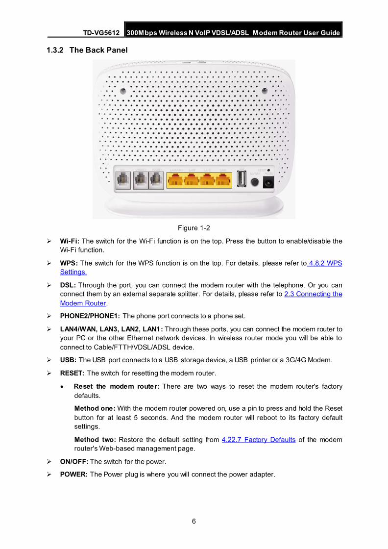
Figure 1-2
Wi-Fi: The switch for the Wi-Fi function is on the top. Press the button to enable/disable the Wi-Fi function.
WPS: The switch for the WPS function is on the top. For details, please refer to 4.8.2 WPS Settings.
DSL: Through the port, you can connect the modem router with the telephone. Or you can connect them by an external separate splitter. For details, please refer to 2.3 Connecting the Modem Router.
PHONE2/PHONE1: The phone port connects to a phone set.
LAN4/WAN, LAN3, LAN2, LAN1: Through these ports, you can connect the modem router to your PC or the other Ethernet network devices. In wireless router mode you will be able to connect to Cable/FTTH/VDSL/ADSL device.
USB: The USB port connects to a USB storage device, a USB printer or a 3G/4G Modem.
RESET: The switch for resetting the modem router.
• Reset the modem router: There are two ways to reset the modem router's factory defaults.
Method one: With the modem router powered on, use a pin to press and hold the Reset button for at least 5 seconds. And the modem router will reboot to its factory default settings.
Method two: Restore the default setting from 4.22.7 Factory Defaults of the modem router's Web-based management page.
ON/OFF: The switch for the power.
POWER: The Power plug is where you will connect the power adapter.
TD-VG5612 300Mbps Wireless N VoIP VDSL/ADSL Modem Router User Guide
7
Chapter 2. Connecting the Modem Router 2.1 System Requirements
Broadband Internet Access Service (DSL/Cable/Ethernet).
PCs with a working Ethernet Adapter and an Ethernet cable with RJ45 connectors.
TCP/IP protocol on each PC.
Web browser, such as Microsoft Internet Explorer, Mozilla Firefox or Apple Safari.
2.2 Installation Environment Requirements
The Product should not be located where it will be exposed to moisture or excessive heat. Place the modem router in a location where it can be connected to the various devices as well
as to a power source. Make sure the cables and power cord are safely placed out of the way so they do not create a
tripping hazard. The modem router can be placed on a shelf or desktop. Keep away from the strong electromagnetic radiation and the device of electromagnetic
sensitive.
2.3 Connecting the Modem Router
Before installing the device, please make sure your broadband service provided by your ISP is available. If there is any problem, please contact your ISP. Before cable connection, cut off the power supply and keep your hands dry. You can follow the steps below to install it.
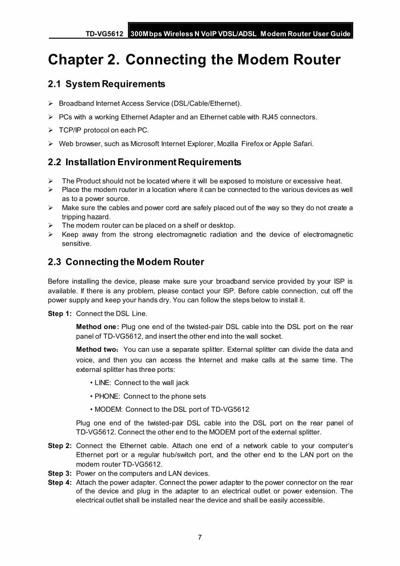
Step 1: Connect the DSL Line.
Method one: Plug one end of the twisted-pair DSL cable into the DSL port on the rear panel of TD-VG5612, and insert the other end into the wall socket.
Method two:You can use a separate splitter. External splitter can divide the data and voice, and then you can access the Internet and make calls at the same time. The external splitter has three ports:
• LINE: Connect to the wall jack
• PHONE: Connect to the phone sets
• MODEM: Connect to the DSL port of TD-VG5612
Plug one end of the twisted-pair DSL cable into the DSL port on the rear panel of TD-VG5612. Connect the other end to the MODEM port of the external splitter.
Step 2: Connect the Ethernet cable. Attach one end of a network cable to your computer’s Ethernet port or a regular hub/switch port, and the other end to the LAN port on the modem router TD-VG5612.
Step 3: Power on the computers and LAN devices. Step 4: Attach the power adapter. Connect the power adapter to the power connector on the rear
of the device and plug in the adapter to an electrical outlet or power extension. The electrical outlet shall be installed near the device and shall be easily accessible.
TD-VG5612 300Mbps Wireless N VoIP VDSL/ADSL Modem Router User Guide
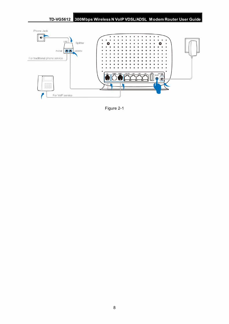
8
Figure 2-1
TD-VG5612 300Mbps Wireless N VoIP VDSL/ADSL Modem Router User Guide
9
Chapter 3. Quick Installation Guide This chapter will show you how to configure the basic functions of your TD-VG5612 300Mbps Wireless N VoIP VDSL/ADSL Modem Router using Quick Setup Wizard within minutes.
3.1 TCP/IP Configuration The default IP address of the TD-VG5612 300Mbps Wireless N VoIP VDSL/ADSL Modem Router is 192.168.1.1. And the default Subnet Mask is 255.255.255.0. These values can be changed as you desire. In this guide, we use all the default values for description.
Connect the local PC to the LAN port of the modem router. And then you can configure the IP address for your PC in the following way.
Obtain an IP address automatically
1) Set up the TCP/IP Protocol in "Obtain an IP address automatically" mode on your PC. If you need instructions as to how to do this, please refer to Appendix B: Trouble shooting.
2) Then the built-in DHCP server will assign IP address for the PC.
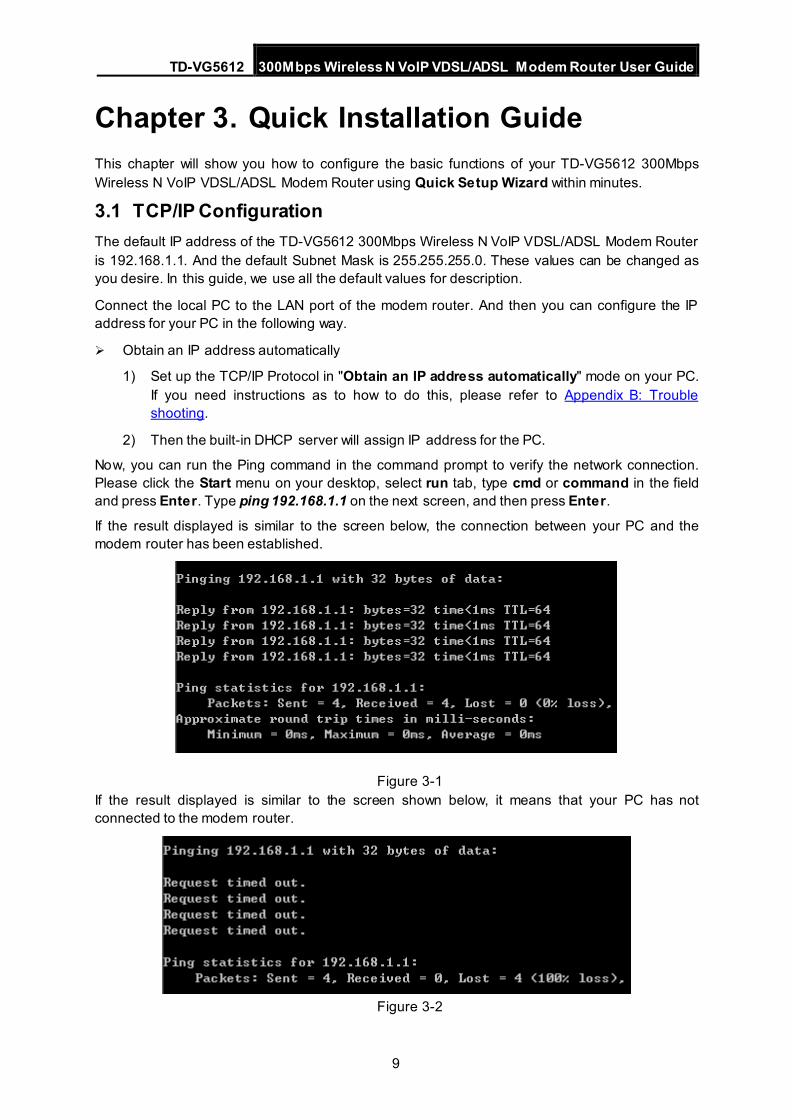
Now, you can run the Ping command in the command prompt to verify the network connection. Please click the Start menu on your desktop, select run tab, type cmd or command in the field and press Enter. Type ping 192.168.1.1 on the next screen, and then press Enter.
If the result displayed is similar to the screen below, the connection between your PC and the modem router has been established.
Figure 3-1 If the result displayed is similar to the screen shown below, it means that your PC has not connected to the modem router.
Figure 3-2
TD-VG5612 300Mbps Wireless N VoIP VDSL/ADSL Modem Router User Guide
10
You can check it following the steps below:
1) Is the connection between your PC and the modem router correct?
The LEDs of LAN port which you link to the device and the LEDs on your PC's adapter should be lit.
2) Is the TCP/IP configuration for your PC correct? If the modem router's IP address is 192.168.1.1, your PC's IP address must be within the range of 192.168.1.2 ~ 192.168.1.254.
3.2 Quick Installation Guide
With a Web-based management page, it is easy to configure and manage the TD-VG5612 300Mbps Wireless N VoIP VDSL/ADSL Modem Router. The Web-based management page can be used on any Windows, Macintosh or UNIX OS with a Web browser, such as Microsoft Internet Explorer, Mozilla Firefox or Apple Safari.
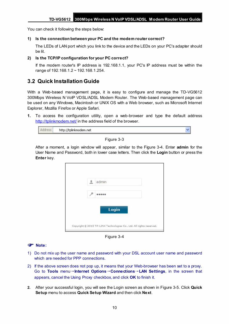
1. To access the configuration utility, open a web-browser and type the default address http://tplinkmodem.net/ in the address field of the browser.
Figure 3-3
After a moment, a login window will appear, similar to the Figure 3-4. Enter admin for the User Name and Password, both in lower case letters. Then click the Login button or press the Enter key.
Figure 3-4
Note:
1) Do not mix up the user name and password with your DSL account user name and password which are needed for PPP connections.
2) If the above screen does not pop up, it means that your Web-browser has been set to a proxy. Go to Tools menu→Internet Options→Connections→LAN Settings, in the screen that appears, cancel the Using Proxy checkbox, and click OK to finish it.
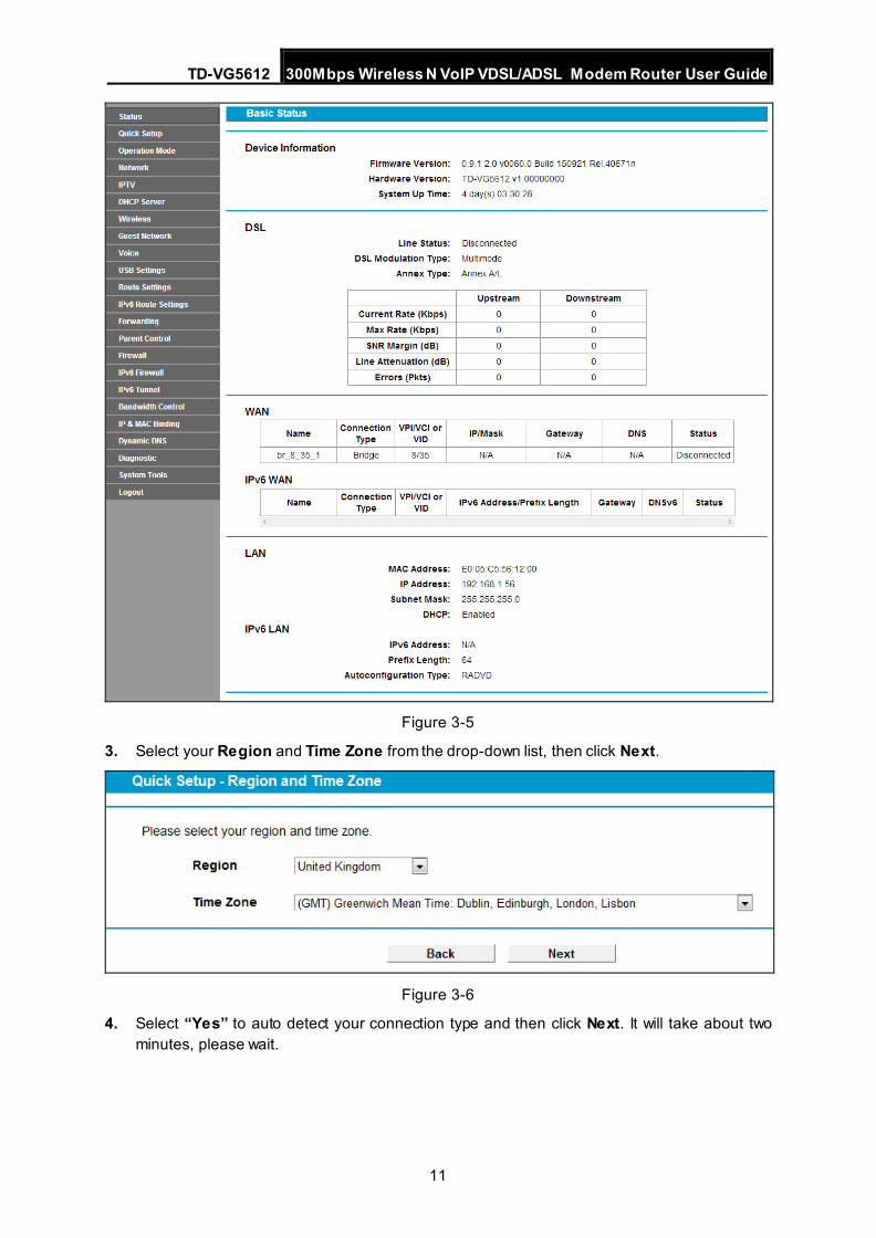
2. After your successful login, you will see the Login screen as shown in Figure 3-5. Click Quick Setup menu to access Quick Setup Wizard and then click Next.
TD-VG5612 300Mbps Wireless N VoIP VDSL/ADSL Modem Router User Guide
11
Figure 3-5
3. Select your Region and Time Zone from the drop-down list, then click Next.
Figure 3-6
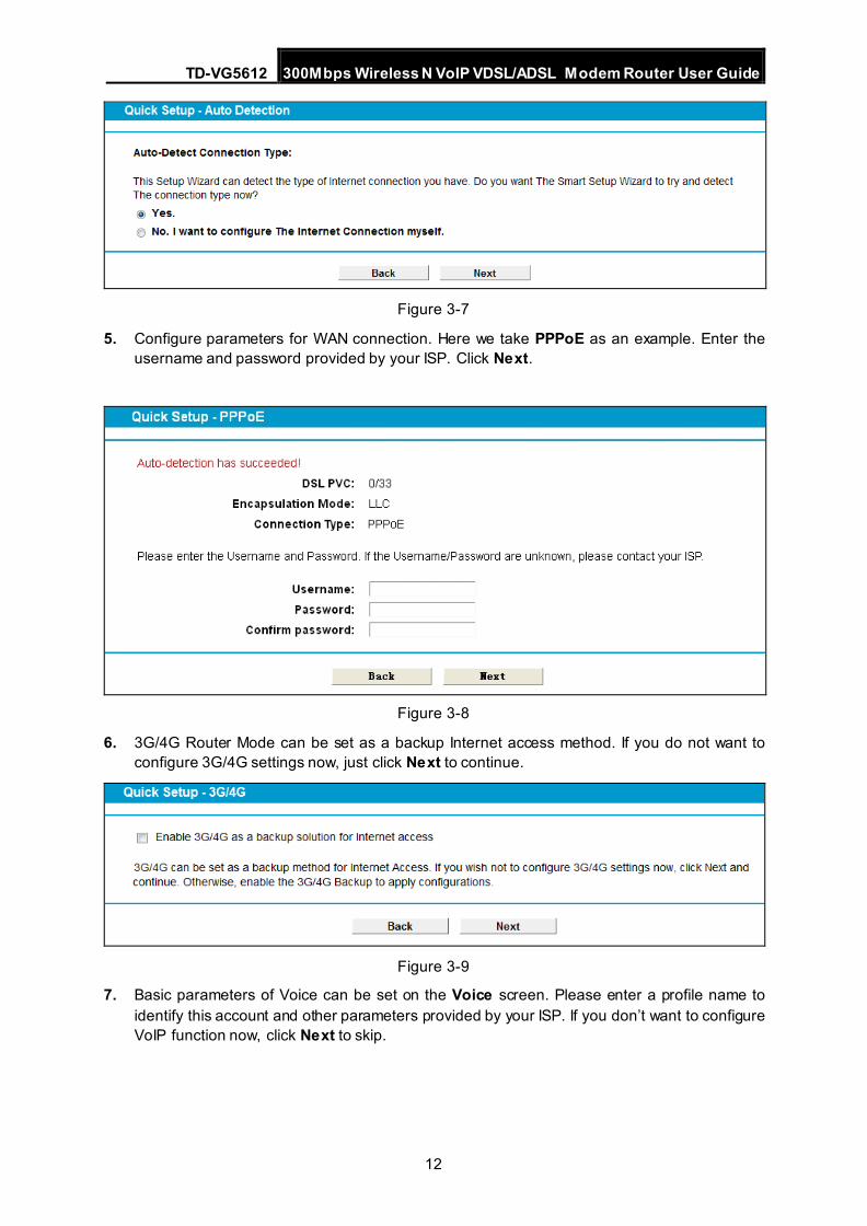
4. Select “Yes” to auto detect your connection type and then click Next. It will take about two minutes, please wait.
TD-VG5612 300Mbps Wireless N VoIP VDSL/ADSL Modem Router User Guide
12
Figure 3-7
5. Configure parameters for WAN connection. Here we take PPPoE as an example. Enter the username and password provided by your ISP. Click Next.
Figure 3-8
6. 3G/4G Router Mode can be set as a backup Internet access method. If you do not want to configure 3G/4G settings now, just click Next to continue.
Figure 3-9
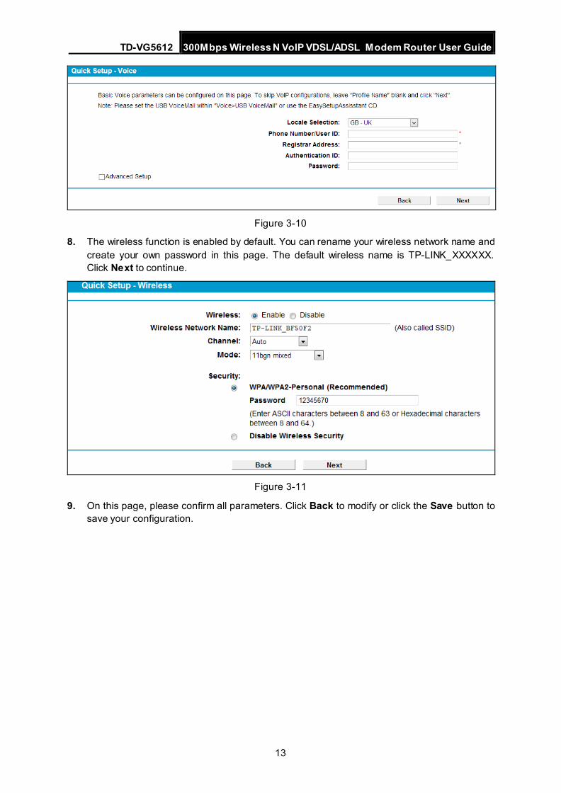
7. Basic parameters of Voice can be set on the Voice screen. Please enter a profile name to identify this account and other parameters provided by your ISP. If you don’t want to configure VoIP function now, click Next to skip.
TD-VG5612 300Mbps Wireless N VoIP VDSL/ADSL Modem Router User Guide
13
Figure 3-10
8. The wireless function is enabled by default. You can rename your wireless network name and create your own password in this page. The default wireless name is TP-LINK_XXXXXX. Click Next to continue.
Figure 3-11
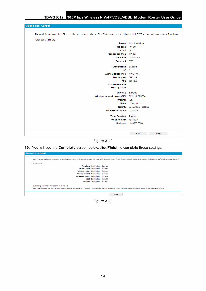
9. On this page, please confirm all parameters. Click Back to modify or click the Save button to save your configuration.
TD-VG5612 300Mbps Wireless N VoIP VDSL/ADSL Modem Router User Guide
14
Figure 3-12
10. You will see the Complete screen below, click Finish to complete these settings.
Figure 3-13
TD-VG5612 300Mbps Wireless N VoIP VDSL/ADSL Modem Router User Guide
15
Chapter 4. Configuring the Modem Router This chapter will show each Web page's key function and the configuration.
4.1 Login
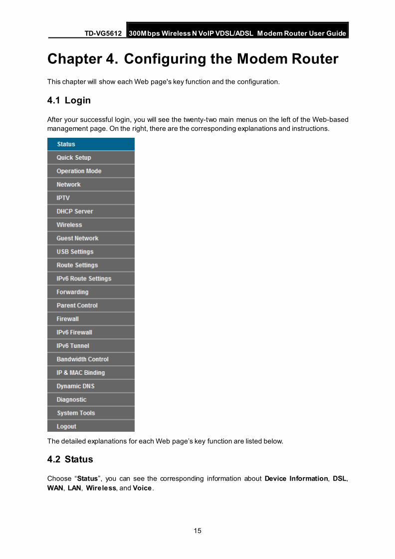
After your successful login, you will see the twenty-two main menus on the left of the Web-based management page. On the right, there are the corresponding explanations and instructions.
The detailed explanations for each Web page’s key function are listed below.
4.2 Status
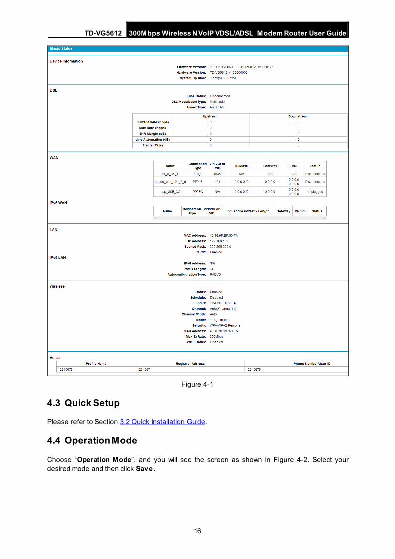
Choose “Status”, you can see the corresponding information about Device Information, DSL, WAN, LAN, Wireless, and Voice .
TD-VG5612 300Mbps Wireless N VoIP VDSL/ADSL Modem Router User Guide
16
Figure 4-1
4.3 Quick Setup
Please refer to Section 3.2 Quick Installation Guide.
4.4 Operation Mode
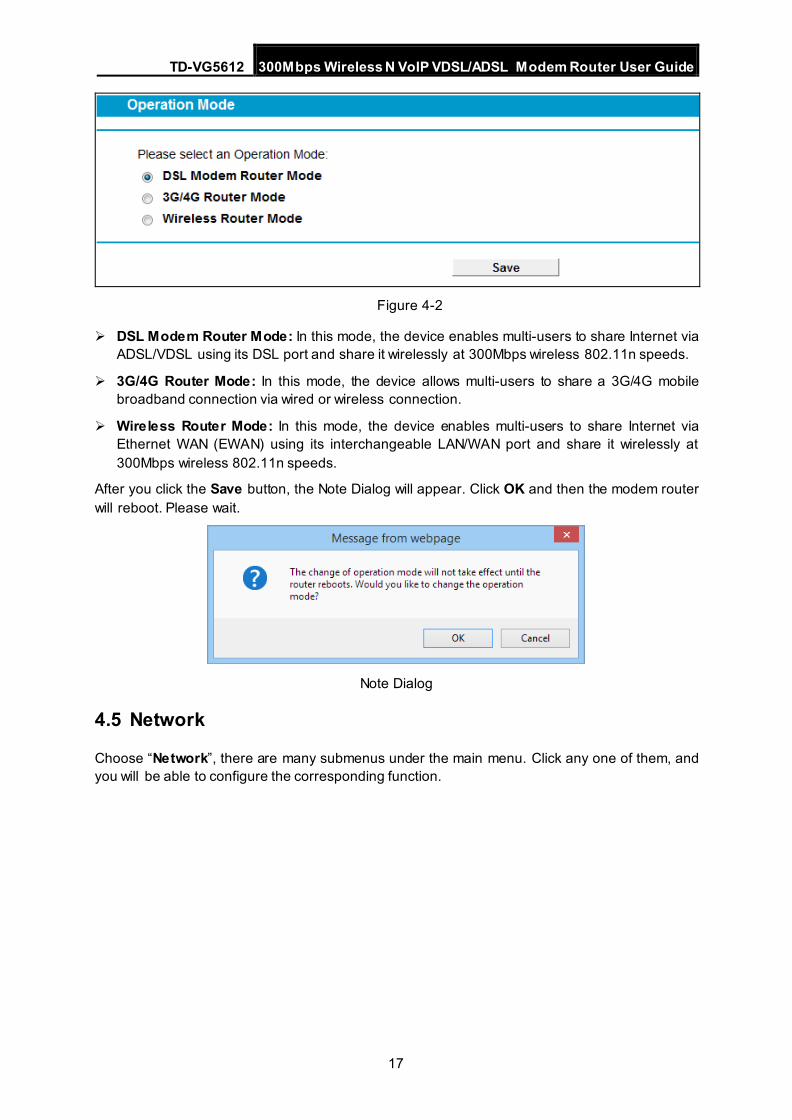
Choose “Operation Mode”, and you will see the screen as shown in Figure 4-2. Select your desired mode and then click Save .
TD-VG5612 300Mbps Wireless N VoIP VDSL/ADSL Modem Router User Guide
17
Figure 4-2
DSL Modem Router Mode: In this mode, the device enables multi-users to share Internet via ADSL/VDSL using its DSL port and share it wirelessly at 300Mbps wireless 802.11n speeds.
3G/4G Router Mode: In this mode, the device allows multi-users to share a 3G/4G mobile broadband connection via wired or wireless connection.
Wireless Router Mode: In this mode, the device enables multi-users to share Internet via Ethernet WAN (EWAN) using its interchangeable LAN/WAN port and share it wirelessly at 300Mbps wireless 802.11n speeds.
After you click the Save button, the Note Dialog will appear. Click OK and then the modem router will reboot. Please wait.
Note Dialog
4.5 Network
Choose “Network”, there are many submenus under the main menu. Click any one of them, and you will be able to configure the corresponding function.
TD-VG5612 300Mbps Wireless N VoIP VDSL/ADSL Modem Router User Guide
18
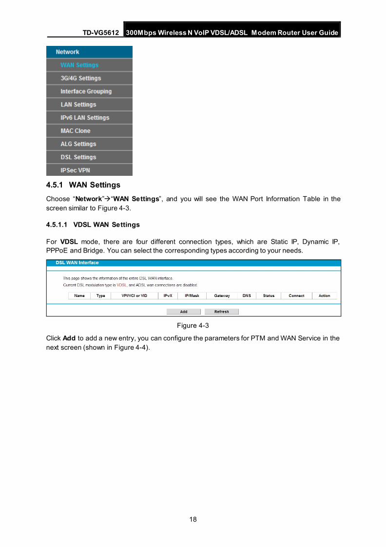
4.5.1 WAN Settings Choose “Network”“WAN Settings”, and you will see the WAN Port Information Table in the screen similar to Figure 4-3.
4.5.1.1 VDSL WAN Settings
For VDSL mode, there are four different connection types, which are Static IP, Dynamic IP, PPPoE and Bridge. You can select the corresponding types according to your needs.
Figure 4-3
Click Add to add a new entry, you can configure the parameters for PTM and WAN Service in the next screen (shown in Figure 4-4).
TD-VG5612 300Mbps Wireless N VoIP VDSL/ADSL Modem Router User Guide
19
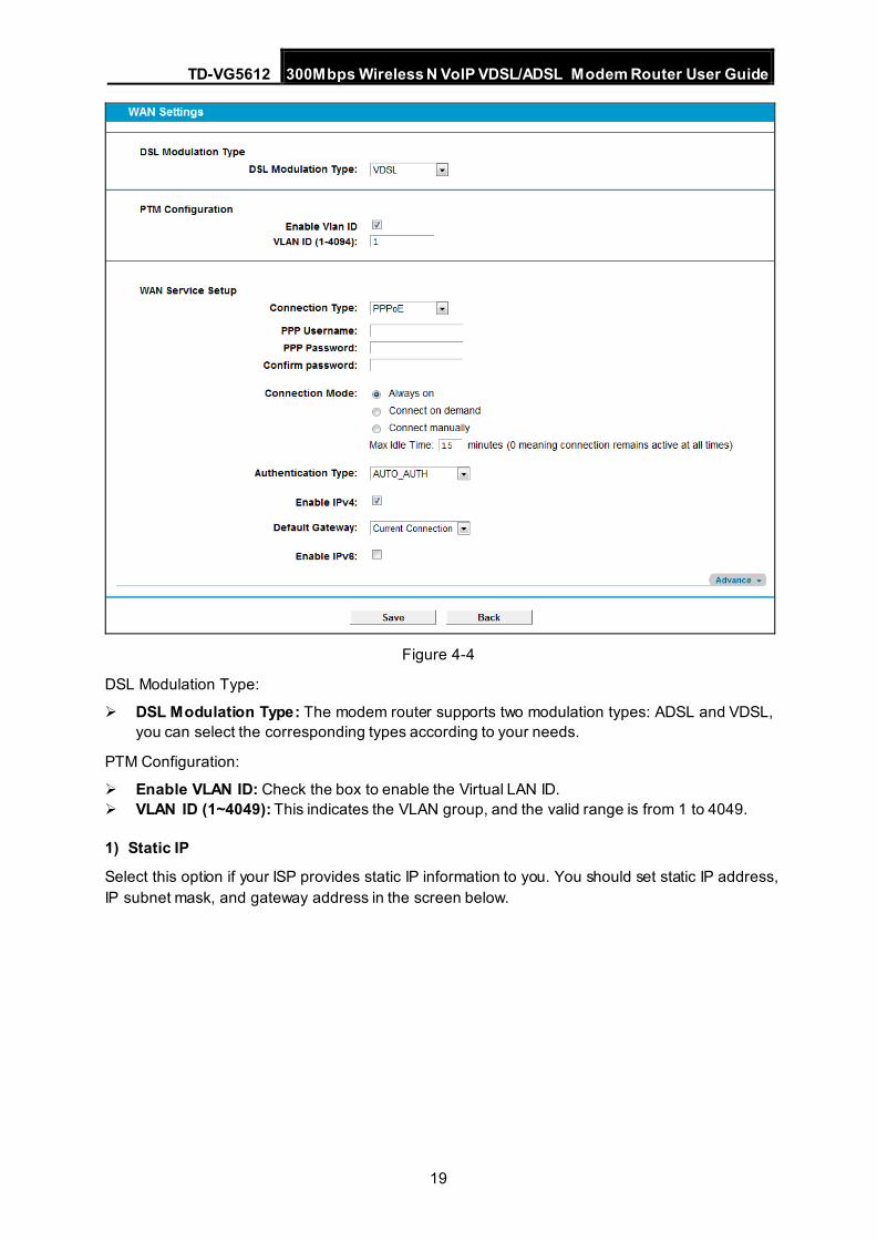
Figure 4-4
DSL Modulation Type:
DSL Modulation Type: The modem router supports two modulation types: ADSL and VDSL, you can select the corresponding types according to your needs.
PTM Configuration:
Enable VLAN ID: Check the box to enable the Virtual LAN ID. VLAN ID (1~4049): This indicates the VLAN group, and the valid range is from 1 to 4049.
1) Static IP
Select this option if your ISP provides static IP information to you. You should set static IP address, IP subnet mask, and gateway address in the screen below.
TD-VG5612 300Mbps Wireless N VoIP VDSL/ADSL Modem Router User Guide
20
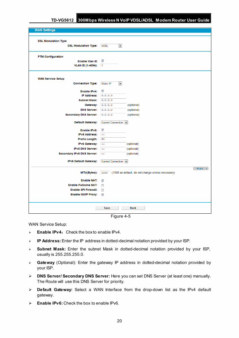
Figure 4-5
WAN Service Setup:
Enable IPv4:Check the box to enable IPv4.
IP Address: Enter the IP address in dotted-decimal notation provided by your ISP.
Subnet Mask: Enter the subnet Mask in dotted-decimal notation provided by your ISP, usually is 255.255.255.0.
Gateway (Optional): Enter the gateway IP address in dotted-decimal notation provided by your ISP.
DNS Server/ Secondary DNS Server: Here you can set DNS Server (at least one) manually. The Route will use this DNS Server for priority.
Default Gateway: Select a WAN Interface from the drop-down list as the IPv4 default gateway.
Enable IPv6: Check the box to enable IPv6.
TD-VG5612 300Mbps Wireless N VoIP VDSL/ADSL Modem Router User Guide
21
IPv6 Address: Enter the IPv6 address provided by your ISP.
Prefix Length: Enter the prefix length of the IPv6 address. The default value is 64.
IPv6 Gateway: Enter the gateway IPv6 address provided by your ISP.
IPv6 DNS Server / Secondary IPv6 DNS Server: Here you can set IPv6 DNS Server (at least one) manually. The Route will use this IPv6 DNS Server for priority.
IPv6 Default Gateway: Select a WAN Interface from the drop-down list as the IPv6 default gateway.
Click Advance , advanced selections of WAN Service Setup can be shown.
MTU (Bytes): Maximum Transmission Unit Size. Check this box then you can change the MTU size. The default MTU value is 1500 Bytes. It is not recommended that you change the default value unless required by your ISP.
Enable NAT: This technology translates the IP addresses of a local area network to a different IP address for the Internet. If this modem router is hosting your network’s connection to the Internet, please select the check box. If another Router exists in your network, you don’t need to select the option.
Enable Fullcone NAT: It is a type of NAT, if not enabled, the default NAT will act.
Enable SPI Firewall: A SPI firewall enhances network’s security. Select the option to use a firewall, or else without a firewall.
Enable IGMP Proxy: IGMP (Internet Group Management Protocol) is used to manage multicasting on TCP/IP networks. Some ISPs use IGMP to perform remote configuration for client devices, such as the modem router. The default value is disabled, and if you are not sure, please contact your ISP or just leave it.
Click the Save button to save the settings.
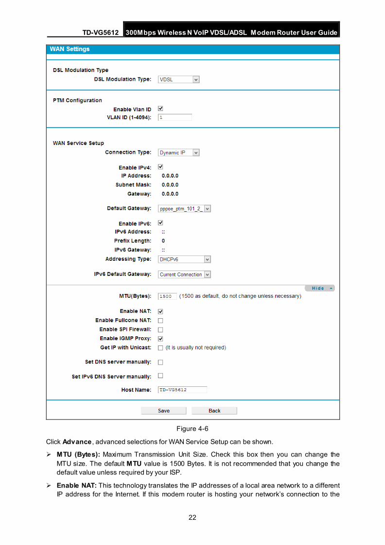
2) Dynamic IP
Select this option, the modem router will be able to obtain IP network information dynamically from a DHCP server provided by your ISP.
TD-VG5612 300Mbps Wireless N VoIP VDSL/ADSL Modem Router User Guide
22
Figure 4-6
Click Advance , advanced selections for WAN Service Setup can be shown.
MTU (Bytes): Maximum Transmission Unit Size. Check this box then you can change the MTU size. The default MTU value is 1500 Bytes. It is not recommended that you change the default value unless required by your ISP.
Enable NAT: This technology translates the IP addresses of a local area network to a different IP address for the Internet. If this modem router is hosting your network’s connection to the
TD-VG5612 300Mbps Wireless N VoIP VDSL/ADSL Modem Router User Guide
23
Internet, please select the check box. If another Router exists in your network, you don’t need to select the option.
Enable Fullcone NAT: It is a type of NAT, if not enabled, the default NAT will act.
Enable SPI Firewall: A SPI firewall enhances network’s security. Select the option to use a firewall, or else without a firewall.
Enable IGMP Proxy: IGMP (Internet Group Management Protocol) is used to manage multicasting on TCP/IP networks. Some ISPs use IGMP to perform remote configuration for client devices, such as the modem router. The default value is disabled, and if you are not sure, please contact your ISP or just leave it.
Get IP with Unicast: This is disabled by default. The minority of DHCP Server of ISP will not support to enable this. When the Route is connected right but IP cannot get, you can select this box.
Set DNS Server manually: Choose “Set DNS Server manually”, you can set DNS Server manually here. The modem router will use this DNS Server for priority.
Get IPv6 Address with Unicast: This is disabled by default. The minority of DHCPv6 Server of ISP will not support to enable this. When the modem router is connected right but cannot get IPv6 address, you can select this box.
Set IPv6 DNS Server manually: Choose “Set IPv6 DNS Server manually”, you can set IPv6 DNS Server manually here. The modem router will use this IPv6 DNS Server for priority.
Host Name: Here displays model No. of your modem router.
Click the Save button to save the settings.
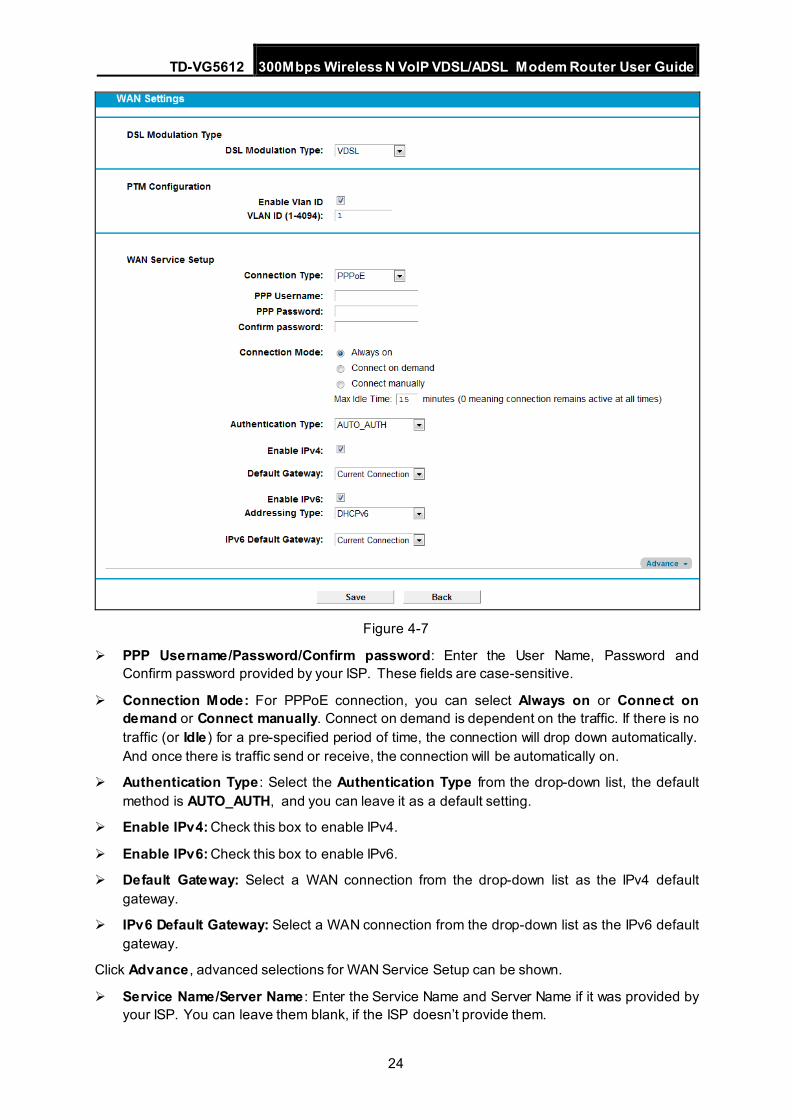
3) PPPoE If your ISP provides a PPPoE connection and you need to use an ATM Interface, choose PPPoE in the drop-down list, and then the screen will be displayed as below.
TD-VG5612 300Mbps Wireless N VoIP VDSL/ADSL Modem Router User Guide
24
Figure 4-7
PPP Username/Password/Confirm password: Enter the User Name, Password and Confirm password provided by your ISP. These fields are case-sensitive.
Connection Mode: For PPPoE connection, you can select Always on or Connect on demand or Connect manually. Connect on demand is dependent on the traffic. If there is no traffic (or Idle) for a pre-specified period of time, the connection will drop down automatically. And once there is traffic send or receive, the connection will be automatically on.
Authentication Type : Select the Authentication Type from the drop-down list, the default method is AUTO_AUTH, and you can leave it as a default setting.
Enable IPv4: Check this box to enable IPv4.
Enable IPv6: Check this box to enable IPv6.
Default Gateway: Select a WAN connection from the drop-down list as the IPv4 default gateway.
IPv6 Default Gateway: Select a WAN connection from the drop-down list as the IPv6 default gateway.
Click Advance , advanced selections for WAN Service Setup can be shown.
Service Name/Server Name : Enter the Service Name and Server Name if it was provided by your ISP. You can leave them blank, if the ISP doesn’t provide them.
TD-VG5612 300Mbps Wireless N VoIP VDSL/ADSL Modem Router User Guide
25
MTU (Bytes): Maximum Transmission Unit Size. Check this box then you can change the MTU size. The default MTU value is 1500 Bytes. It is not recommended that you change the default value unless required by your ISP.
Enable Fullcone NAT: It is a type of NAT, if not enabled, the default NAT will act.
Enable SPI Firewall: A SPI firewall enhances network’s security. Select the option to use a firewall, or else without a firewall.
Enable IGMP Proxy: IGMP (Internet Group Management Protocol) is used to manage multicasting on TCP/IP networks. Some ISPs use IGMP to perform remote configuration for client devices, such as the modem router. The default value is disabled, and if you are not sure, please contact your ISP or just leave it.
Use IP address specified by ISP: Choose “Use IP address specified by ISP”, you can enter the IP address provided by your ISP.
Set DNS Server manually: Choose “Set DNS Server manually”, you can set DNS Server manually here. The modem router will use this DNS Server for priority.
Use IPv6 address specified by ISP: Choose “Use IPv6 address specified by ISP”, you can enter the IPv6 address provided by your ISP.
Set IPv6 DNS Server manually: Choose “Set IPv6 DNS Server manually”, you can set IPv6 DNS Server manually here. The modem router will use this IPv6 DNS Server for priority.
Click the Save button to save the settings.
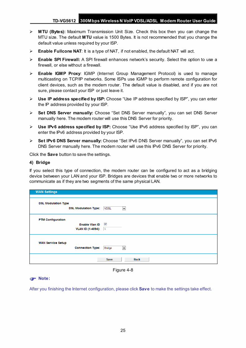
4) Bridge
If you select this type of connection, the modem router can be configured to act as a bridging device between your LAN and your ISP. Bridges are devices that enable two or more networks to communicate as if they are two segments of the same physical LAN.
Figure 4-8
Note:
After you finishing the Internet configuration, please click Save to make the settings take effect.
TD-VG5612 300Mbps Wireless N VoIP VDSL/ADSL Modem Router User Guide
26
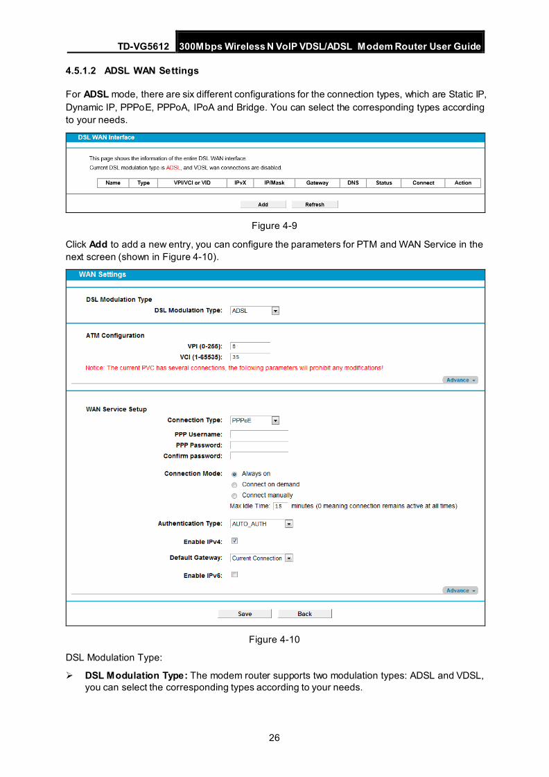
4.5.1.2 ADSL WAN Settings
For ADSL mode, there are six different configurations for the connection types, which are Static IP, Dynamic IP, PPPoE, PPPoA, IPoA and Bridge. You can select the corresponding types according to your needs.
Figure 4-9
Click Add to add a new entry, you can configure the parameters for PTM and WAN Service in the next screen (shown in Figure 4-10).
Figure 4-10
DSL Modulation Type:
DSL Modulation Type: The modem router supports two modulation types: ADSL and VDSL, you can select the corresponding types according to your needs.
TD-VG5612 300Mbps Wireless N VoIP VDSL/ADSL Modem Router User Guide
27
ATM Configuration:
VPI (0~255): Identifies the virtual path between endpoints in an ATM network. The valid range is from 0 to 255. Please input the value provided by your ISP.
VCI (1~65535): Identifies the virtual channel endpoints in an ATM network. The valid range is from 1 to 65535 (1 to 31 is reserved for well-known protocols). Please input the value provided by your ISP.
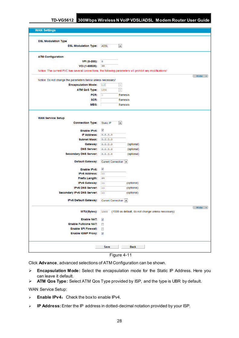
1) Static IP
Select this option if your ISP provides static IP information to you. You should set static IP address, IP subnet mask, and gateway address in the screen below.
TD-VG5612 300Mbps Wireless N VoIP VDSL/ADSL Modem Router User Guide
28
Figure 4-11
Click Advance , advanced selections of ATM Configuration can be shown.
Encapsulation Mode: Select the encapsulation mode for the Static IP Address. Here you can leave it default.
ATM Qos Type: Select ATM Qos Type provided by ISP, and the type is UBR by default.
WAN Service Setup:
Enable IPv4:Check the box to enable IPv4.
IP Address: Enter the IP address in dotted-decimal notation provided by your ISP.
TD-VG5612 300Mbps Wireless N VoIP VDSL/ADSL Modem Router User Guide
29
Subnet Mask: Enter the subnet Mask in dotted-decimal notation provided by your ISP, usually is 255.255.255.0.
Gateway (Optional): Enter the gateway IP address in dotted-decimal notation provided by your ISP.
DNS Server/ Secondary DNS Server: Here you can set DNS Server (at least one) manually. The Route will use this DNS Server for priority.
Default Gateway: Select a WAN Interface from the drop-down list as the IPv4 default gateway.
Enable IPv6: Check the box to enable IPv6.
IPv6 Address: Enter the IPv6 address provided by your ISP.
Prefix Length: Enter the prefix length of the IPv6 address. The default value is 64.
IPv6 Gateway: Enter the gateway IPv6 address provided by your ISP.
IPv6 DNS Server / Secondary IPv6 DNS Server: Here you can set IPv6 DNS Server (at least one) manually. The Route will use this IPv6 DNS Server for priority.
IPv6 Default Gateway: Select a WAN Interface from the drop-down list as the IPv6 default gateway.
Click Advance , advanced selections of WAN Service Setup can be shown.
MTU (Bytes): Maximum Transmission Unit Size. Check this box then you can change the MTU size. The default MTU value is 1500 Bytes. It is not recommended that you change the default value unless required by your ISP.
Enable NAT: This technology translates the IP addresses of a local area network to a different IP address for the Internet. If this modem router is hosting your network’s connection to the Internet, please select the check box. If another Router exists in your network, you don’t need to select the option.
Enable Fullcone NAT: It is a type of NAT, if not enabled, the default NAT will act.
Enable SPI Firewall: A SPI firewall enhances network’s security. Select the option to use a firewall, or else without a firewall.
Enable IGMP Proxy: IGMP (Internet Group Management Protocol) is used to manage multicasting on TCP/IP networks. Some ISPs use IGMP to perform remote configuration for client devices, such as the modem router. The default value is disabled, and if you are not sure, please contact your ISP or just leave it.
Click the Save button to save the settings.
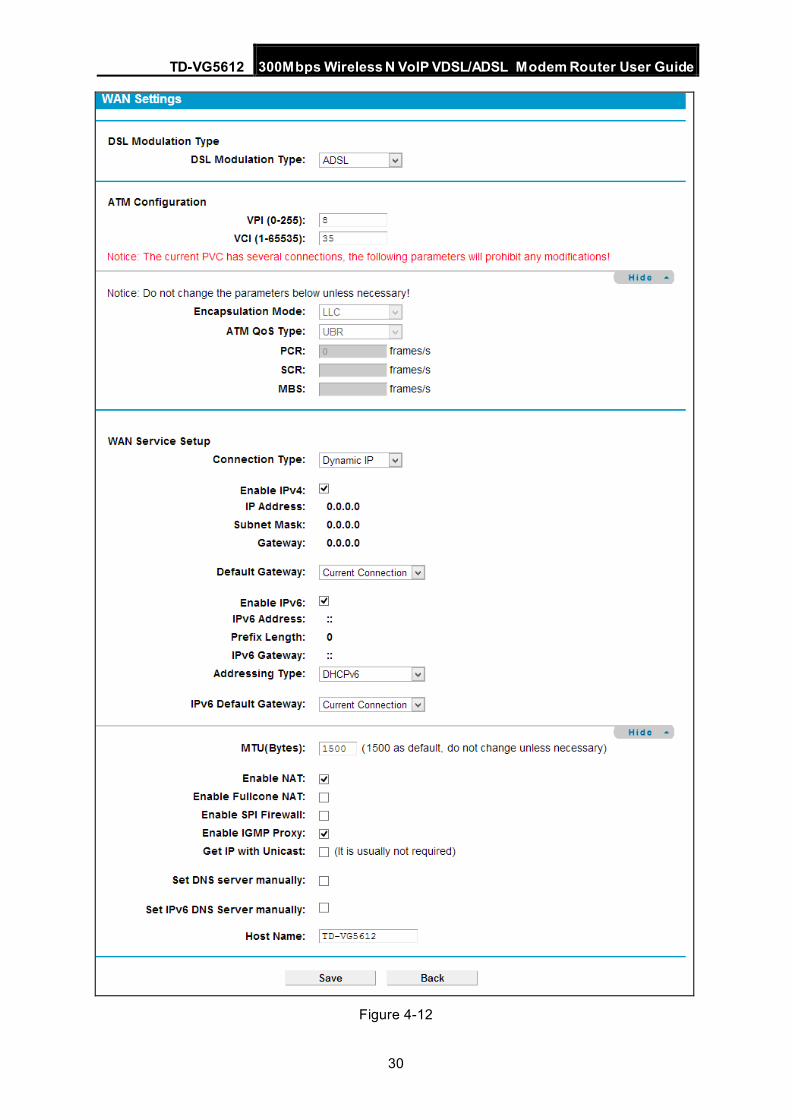
2) Dynamic IP
Select this option, the modem router will be able to obtain IP network information dynamically from a DHCP server provided by your ISP.
TD-VG5612 300Mbps Wireless N VoIP VDSL/ADSL Modem Router User Guide
30
Figure 4-12
TD-VG5612 300Mbps Wireless N VoIP VDSL/ADSL Modem Router User Guide
31
Click Advance , advanced selections for WAN Service Setup can be shown.
MTU (Bytes): Maximum Transmission Unit Size. Check this box then you can change the MTU size. The default MTU value is 1500 Bytes. It is not recommended that you change the default value unless required by your ISP.
Enable NAT: This technology translates the IP addresses of a local area network to a different IP address for the Internet. If this modem router is hosting your network’s connection to the Internet, please select the check box. If another Router exists in your network, you don’t need to select the option.
Enable Fullcone NAT: It is a type of NAT, if not enabled, the default NAT will act.
Enable SPI Firewall: A SPI firewall enhances network’s security. Select the option to use a firewall, or else without a firewall.
Enable IGMP Proxy: IGMP (Internet Group Management Protocol) is used to manage multicasting on TCP/IP networks. Some ISPs use IGMP to perform remote configuration for client devices, such as the modem router. The default value is disabled, and if you are not sure, please contact your ISP or just leave it.
Get IP with Unicast: This is disabled by default. The minority of DHCP Server of ISP will not support to enable this. When the Route is connected right but IP cannot get, you can select this box.
Set DNS Server manually: Choose “Set DNS Server manually”, you can set DNS Server manually here. The modem router will use this DNS Server for priority.
Get IPv6 Address with Unicast: This is disabled by default. The minority of DHCPv6 Server of ISP will not support to enable this. When the modem router is connected right but IPv6 address cannot get, you can select this box.
Set IPv6 DNS Server manually: Choose “Set IPv6 DNS Server manually”, you can set IPv6 DNS Server manually here. The modem router will use this IPv6 DNS Server for priority.
Host Name: Here displays model No. of your modem router.
Click the Save button to save the settings.
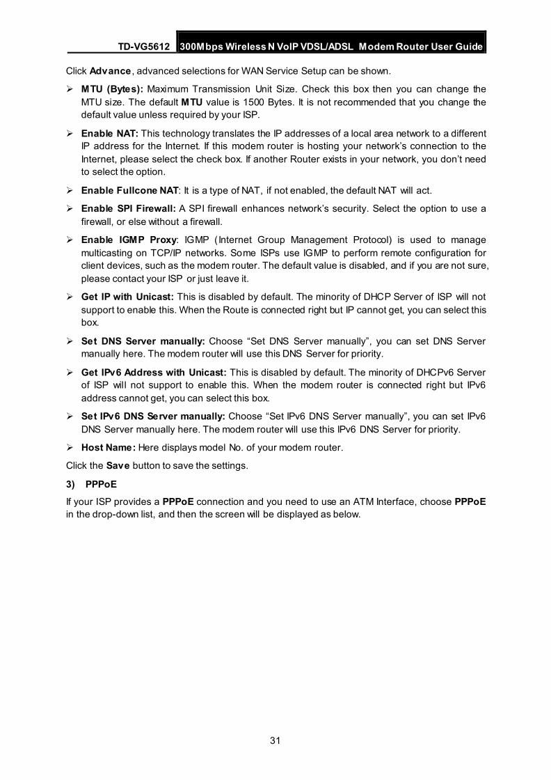
3) PPPoE If your ISP provides a PPPoE connection and you need to use an ATM Interface, choose PPPoE in the drop-down list, and then the screen will be displayed as below.
TD-VG5612 300Mbps Wireless N VoIP VDSL/ADSL Modem Router User Guide
32
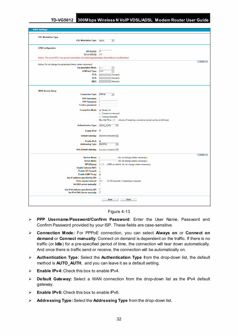
Figure 4-13
PPP Username/Password/Confirm Password: Enter the User Name, Password and Confirm Password provided by your ISP. These fields are case-sensitive.
Connection Mode: For PPPoE connection, you can select Always on or Connect on demand or Connect manually. Connect on demand is dependent on the traffic. If there is no traffic (or Idle) for a pre-specified period of time, the connection will tear down automatically. And once there is traffic send or receive, the connection will be automatically on.
Authentication Type : Select the Authentication Type from the drop-down list, the default method is AUTO_AUTH, and you can leave it as a default setting.
Enable IPv4: Check this box to enable IPv4.
Default Gateway: Select a WAN connection from the drop-down list as the IPv4 default gateway.
Enable IPv6: Check this box to enable IPv6.
Addressing Type: Select the Addressing Type from the drop-down list.

TD-VG5612 300Mbps Wireless N VoIP VDSL/ADSL Modem Router User Guide
33
IPv6 Default Gateway: Select a WAN connection from the drop-down list as the IPv6 default gateway.
Click Advance , advanced selections for WAN Service Setup can be shown.
Service Name/Server Name : Enter the Service Name and Server Name if it was provided by your ISP. You can leave them blank, if the ISP doesn’t provide them.
MTU (Bytes): Maximum Transmission Unit Size. Check this box then you can change the MTU size. The default MTU value is 1500 Bytes. It is not recommended that you change the default value unless required by your ISP.
Enable Fullcone NAT: It is a type of NAT, if not enabled, the default NAT will act.
Enable SPI Firewall: A SPI firewall enhances network’s security. Select the option to use a firewall, or else without a firewall.
Enable IGMP Proxy: IGMP (Internet Group Management Protocol) is used to manage multicasting on TCP/IP networks. Some ISPs use IGMP to perform remote configuration for client devices, such as the modem router. The default value is disabled, and if you are not sure, please contact your ISP or just leave it.
Use IP address specified by ISP: Choose “Use IP address specified by ISP”, you can enter the IP address provided by your ISP.
Echo request interval: The router will detect Access Concentrator online at every interval. The default value is “0”. You can input the value between “0” and “120”. The value “0” means no detect.
Set DNS Server manually: Choose “Set DNS Server manually”, you can set DNS Server manually here. The modem router will use this DNS Server for priority.
Use IPv6 address specified by ISP: Choose “Use IPv6 address specified by ISP”, you can enter the IPv6 address provided by your ISP.
Set IPv6 DNS Server manually: Choose “Set IPv6 DNS Server manually”, you can set IPv6 DNS Server manually here. The modem router will use this IPv6 DNS Server for priority.
Click the Save button to save the settings.
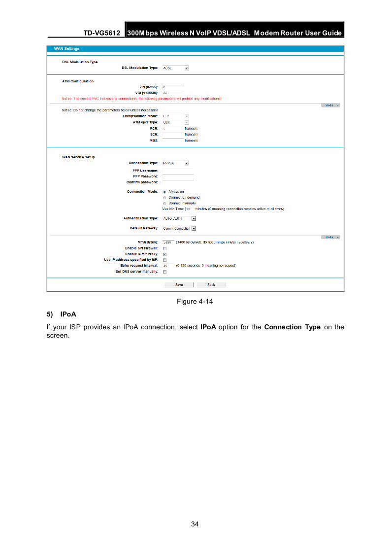
4) PPPoA
If your ISP provides a PPPoA connection and you need to use an ATM Interface, choose PPPoA in the drop-down list, and then the screen will be displayed as below.
The configuration is similar to PPPoE. Please refer to the section 3) PPPoE to configure this part.
TD-VG5612 300Mbps Wireless N VoIP VDSL/ADSL Modem Router User Guide
34
Figure 4-14
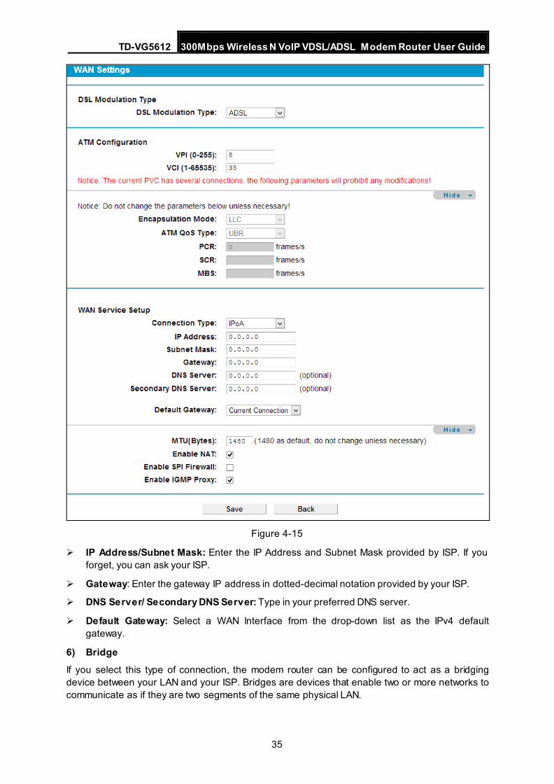
5) IPoA
If your ISP provides an IPoA connection, select IPoA option for the Connection Type on the screen.
TD-VG5612 300Mbps Wireless N VoIP VDSL/ADSL Modem Router User Guide
35
Figure 4-15
IP Address/Subnet Mask: Enter the IP Address and Subnet Mask provided by ISP. If you forget, you can ask your ISP.
Gateway: Enter the gateway IP address in dotted-decimal notation provided by your ISP.
DNS Server/ Secondary DNS Server: Type in your preferred DNS server.
Default Gateway: Select a WAN Interface from the drop-down list as the IPv4 default gateway.
6) Bridge If you select this type of connection, the modem router can be configured to act as a bridging device between your LAN and your ISP. Bridges are devices that enable two or more networks to communicate as if they are two segments of the same physical LAN.
TD-VG5612 300Mbps Wireless N VoIP VDSL/ADSL Modem Router User Guide
36
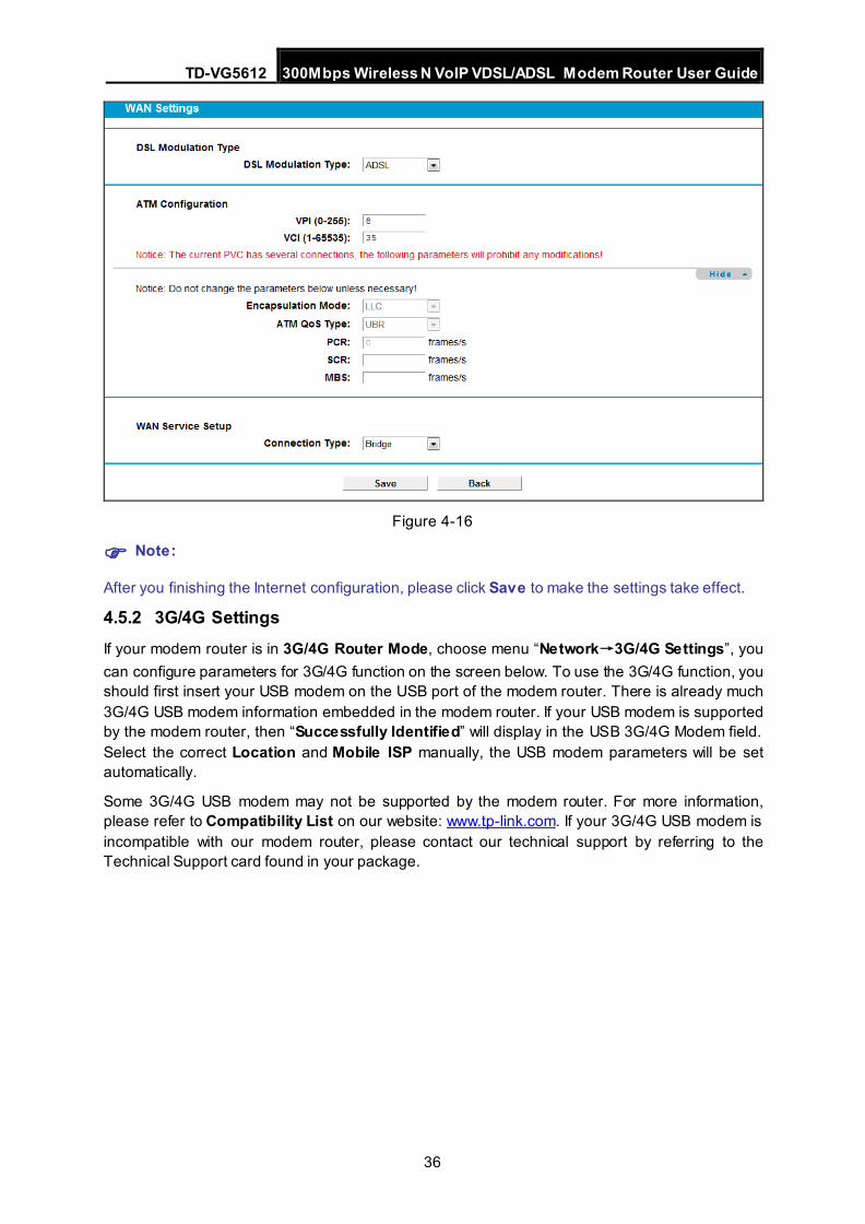
Figure 4-16
Note:
After you finishing the Internet configuration, please click Save to make the settings take effect.
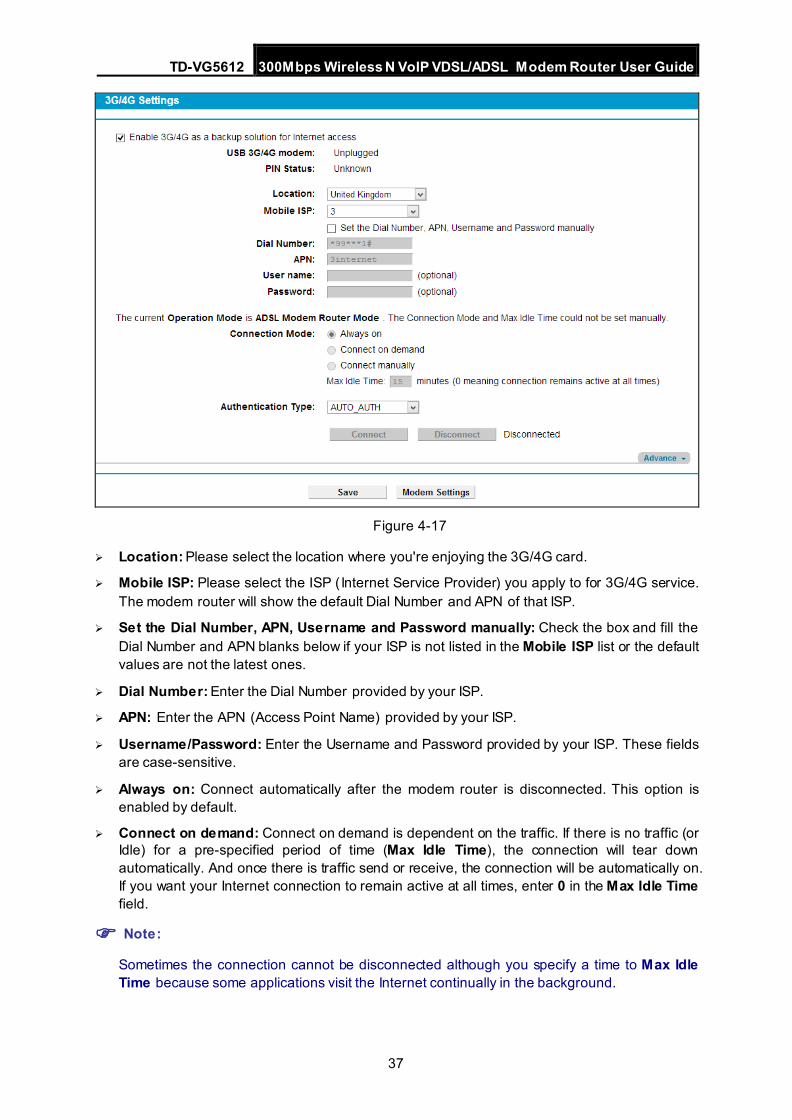
4.5.2 3G/4G Settings If your modem router is in 3G/4G Router Mode, choose menu “Network→3G/4G Settings”, you can configure parameters for 3G/4G function on the screen below. To use the 3G/4G function, you should first insert your USB modem on the USB port of the modem router. There is already much 3G/4G USB modem information embedded in the modem router. If your USB modem is supported by the modem router, then “Successfully Identified” will display in the USB 3G/4G Modem field. Select the correct Location and Mobile ISP manually, the USB modem parameters will be set automatically.
Some 3G/4G USB modem may not be supported by the modem router. For more information, please refer to Compatibility List on our website: www.tp-link.com. If your 3G/4G USB modem is incompatible with our modem router, please contact our technical support by referring to the Technical Support card found in your package.
TD-VG5612 300Mbps Wireless N VoIP VDSL/ADSL Modem Router User Guide
37
Figure 4-17
Location: Please select the location where you're enjoying the 3G/4G card.
Mobile ISP: Please select the ISP (Internet Service Provider) you apply to for 3G/4G service. The modem router will show the default Dial Number and APN of that ISP.
Set the Dial Number, APN, Username and Password manually: Check the box and fill the Dial Number and APN blanks below if your ISP is not listed in the Mobile ISP list or the default values are not the latest ones.
Dial Number: Enter the Dial Number provided by your ISP.
APN: Enter the APN (Access Point Name) provided by your ISP.
Username/Password: Enter the Username and Password provided by your ISP. These fields are case-sensitive.
Always on: Connect automatically after the modem router is disconnected. This option is enabled by default.
Connect on demand: Connect on demand is dependent on the traffic. If there is no traffic (or Idle) for a pre-specified period of time (Max Idle Time), the connection will tear down automatically. And once there is traffic send or receive, the connection will be automatically on. If you want your Internet connection to remain active at all times, enter 0 in the Max Idle Time field.
Note:
Sometimes the connection cannot be disconnected although you specify a time to Max Idle Time because some applications visit the Internet continually in the background.
TD-VG5612 300Mbps Wireless N VoIP VDSL/ADSL Modem Router User Guide
38
Connect manually: You can click the Connect/Disconnect button to connect/disconnect connection immediately. This mode also supports the Max Idle Time function as Connect on demand mode. If you want your Internet connection to remain active at all times, enter 0 in the Max Idle Time field.
Authentication Type: Some ISPs need a specific authentication type, please confirm it with your ISP or keep the default settings.
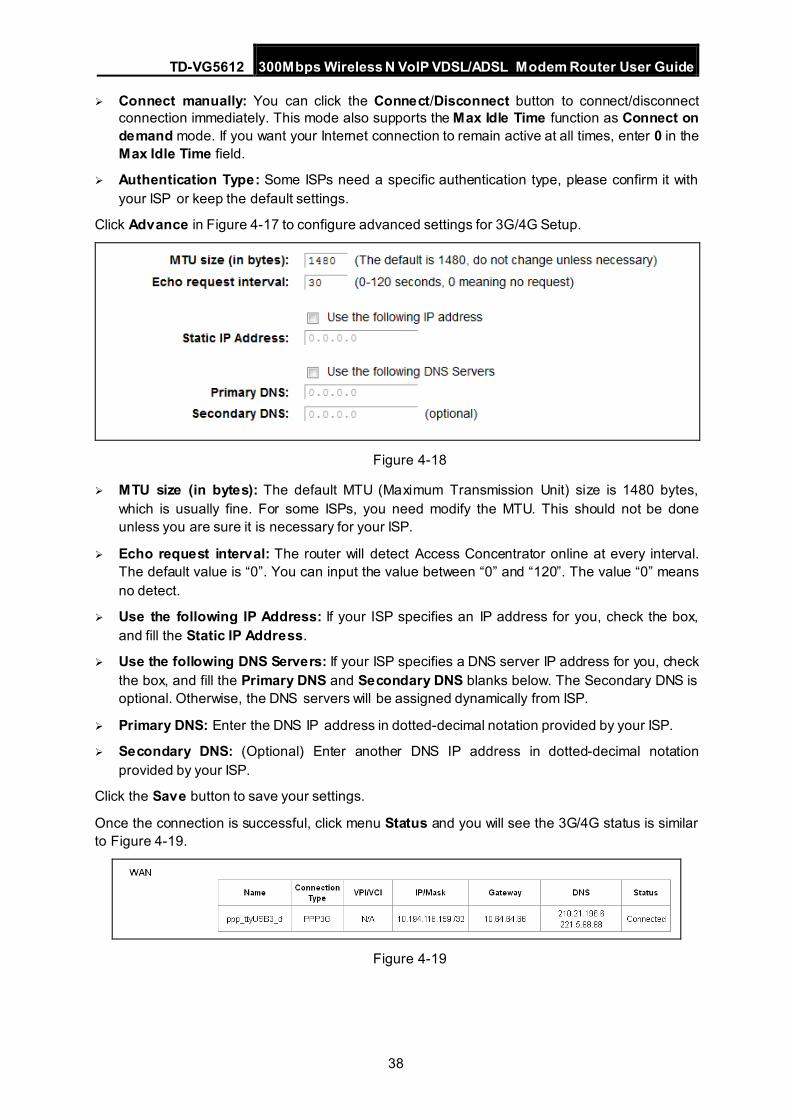
Click Advance in Figure 4-17 to configure advanced settings for 3G/4G Setup.
Figure 4-18
MTU size (in bytes): The default MTU (Maximum Transmission Unit) size is 1480 bytes, which is usually fine. For some ISPs, you need modify the MTU. This should not be done unless you are sure it is necessary for your ISP.
Echo request interval: The router will detect Access Concentrator online at every interval. The default value is “0”. You can input the value between “0” and “120”. The value “0” means no detect.
Use the following IP Address: If your ISP specifies an IP address for you, check the box, and fill the Static IP Address.
Use the following DNS Servers: If your ISP specifies a DNS server IP address for you, check the box, and fill the Primary DNS and Secondary DNS blanks below. The Secondary DNS is optional. Otherwise, the DNS servers will be assigned dynamically from ISP.
Primary DNS: Enter the DNS IP address in dotted-decimal notation provided by your ISP.
Secondary DNS: (Optional) Enter another DNS IP address in dotted-decimal notation provided by your ISP.
Click the Save button to save your settings.
Once the connection is successful, click menu Status and you will see the 3G/4G status is similar to Figure 4-19.
Figure 4-19
TD-VG5612 300Mbps Wireless N VoIP VDSL/ADSL Modem Router User Guide
39
Note:
After connecting a 4G modem to the modem router, please access the Web-based management page by typing http://tplinkmodem.net/ in the address field of the browser and press Enter.
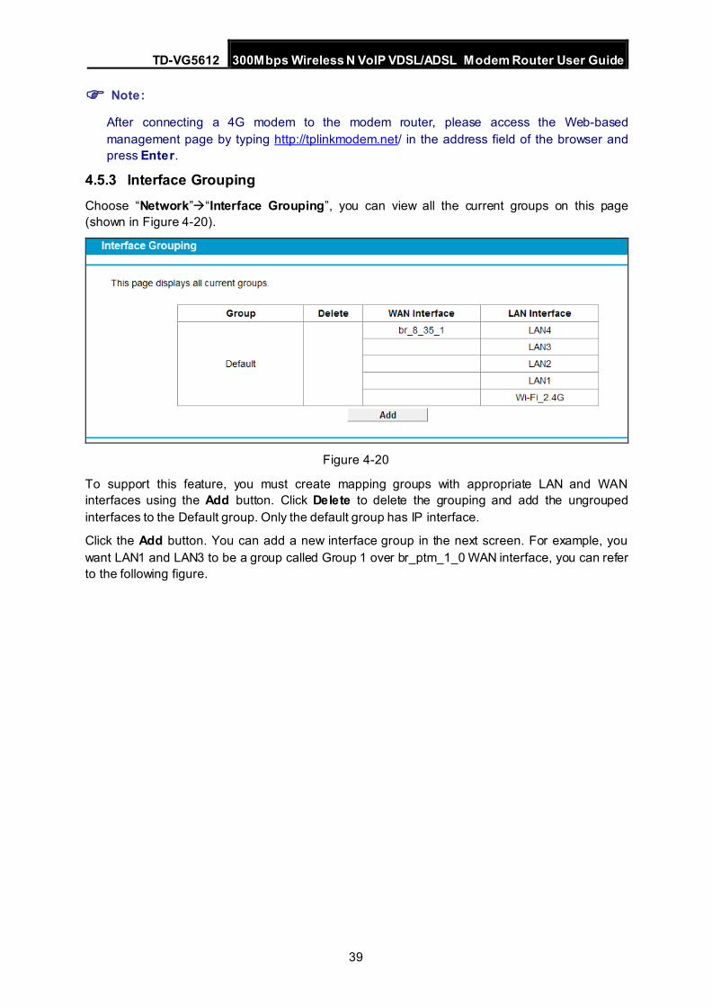
4.5.3 Interface Grouping Choose “Network”“Interface Grouping”, you can view all the current groups on this page (shown in Figure 4-20).
Figure 4-20
To support this feature, you must create mapping groups with appropriate LAN and WAN interfaces using the Add button. Click Delete to delete the grouping and add the ungrouped interfaces to the Default group. Only the default group has IP interface.
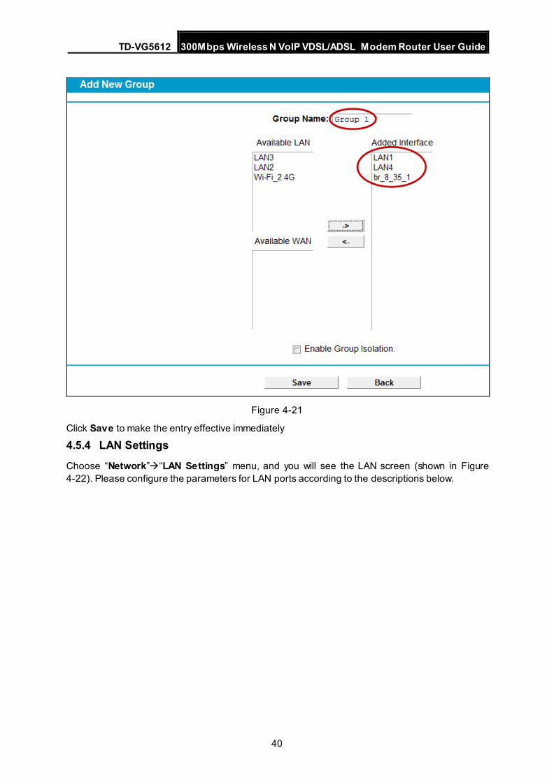
Click the Add button. You can add a new interface group in the next screen. For example, you want LAN1 and LAN3 to be a group called Group 1 over br_ptm_1_0 WAN interface, you can refer to the following figure.
TD-VG5612 300Mbps Wireless N VoIP VDSL/ADSL Modem Router User Guide
40
Figure 4-21
Click Save to make the entry effective immediately
4.5.4 LAN Settings
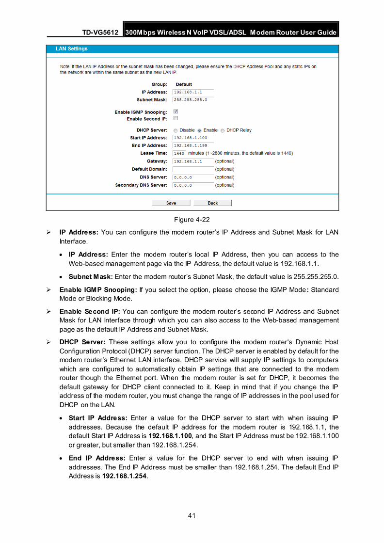
Choose “Network”“LAN Settings” menu, and you will see the LAN screen (shown in Figure 4-22). Please configure the parameters for LAN ports according to the descriptions below.
TD-VG5612 300Mbps Wireless N VoIP VDSL/ADSL Modem Router User Guide
41
Figure 4-22
IP Address: You can configure the modem router’s IP Address and Subnet Mask for LAN Interface.
• IP Address: Enter the modem router’s local IP Address, then you can access to the Web-based management page via the IP Address, the default value is 192.168.1.1.
• Subnet Mask: Enter the modem router’s Subnet Mask, the default value is 255.255.255.0.
Enable IGMP Snooping: If you select the option, please choose the IGMP Mode: Standard Mode or Blocking Mode.
Enable Second IP: You can configure the modem router’s second IP Address and Subnet Mask for LAN Interface through which you can also access to the Web-based management page as the default IP Address and Subnet Mask.
DHCP Server: These settings allow you to configure the modem router‘s Dynamic Host Configuration Protocol (DHCP) server function. The DHCP server is enabled by default for the modem router’s Ethernet LAN interface. DHCP service will supply IP settings to computers which are configured to automatically obtain IP settings that are connected to the modem router though the Ethernet port. When the modem router is set for DHCP, it becomes the default gateway for DHCP client connected to it. Keep in mind that if you change the IP address of the modem router, you must change the range of IP addresses in the pool used for DHCP on the LAN.
• Start IP Address: Enter a value for the DHCP server to start with when issuing IP addresses. Because the default IP address for the modem router is 192.168.1.1, the default Start IP Address is 192.168.1.100, and the Start IP Address must be 192.168.1.100 or greater, but smaller than 192.168.1.254.
• End IP Address: Enter a value for the DHCP server to end with when issuing IP addresses. The End IP Address must be smaller than 192.168.1.254. The default End IP Address is 192.168.1.254.
TD-VG5612 300Mbps Wireless N VoIP VDSL/ADSL Modem Router User Guide
42
• Lease Time: The Lease Time is the amount of time in which a network user will be allowed connection to the modem router with their current dynamic IP address. Enter the amount of time, in hours, then the user will be “leased” this dynamic IP address. After the dynamic IP address has expired, the user will be automatically assigned a new dynamic IP address. The default is 1440 minutes.
The detailed configuration about DHCP server, please refer to section 4.7 DHCP Server.
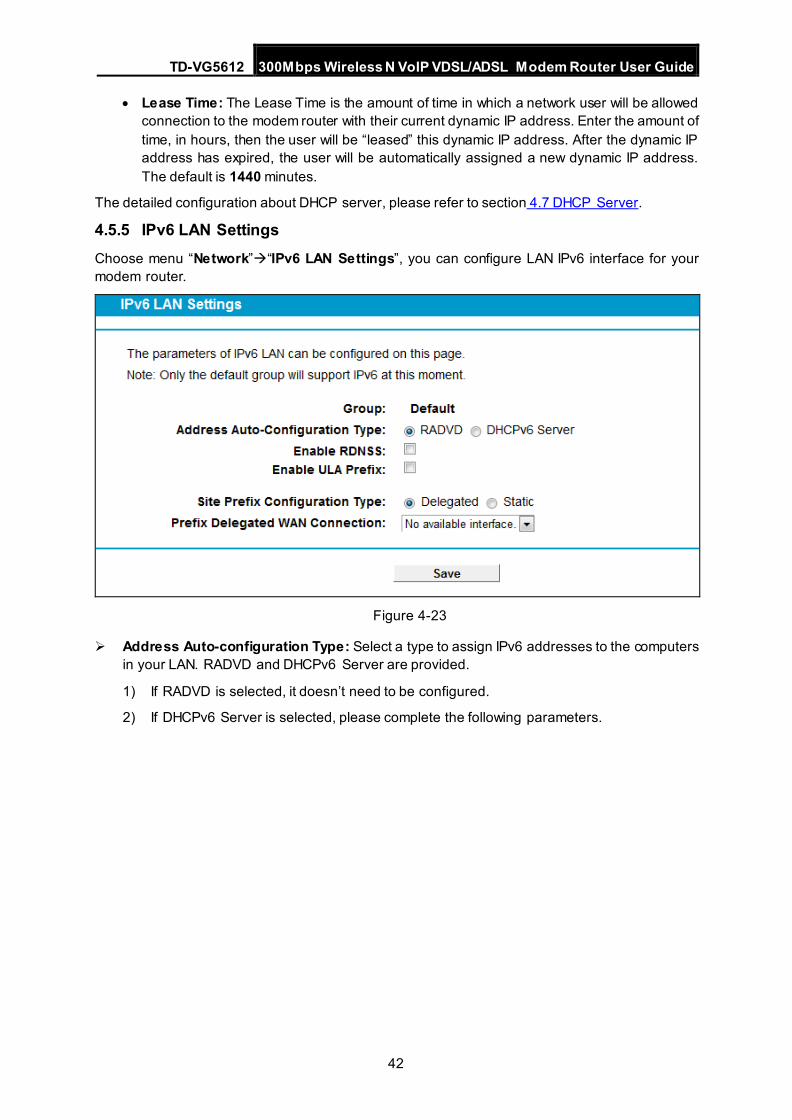
4.5.5 IPv6 LAN Settings Choose menu “Network”“IPv6 LAN Settings”, you can configure LAN IPv6 interface for your modem router.
Figure 4-23
Address Auto-configuration Type: Select a type to assign IPv6 addresses to the computers in your LAN. RADVD and DHCPv6 Server are provided.
1) If RADVD is selected, it doesn’t need to be configured.
2) If DHCPv6 Server is selected, please complete the following parameters.
TD-VG5612 300Mbps Wireless N VoIP VDSL/ADSL Modem Router User Guide
43
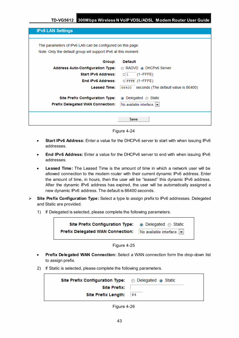
Figure 4-24
• Start IPv6 Address: Enter a value for the DHCPv6 server to start with when issuing IPv6 addresses.
• End IPv6 Address: Enter a value for the DHCPv6 server to end with when issuing IPv6 addresses.
• Leased Time: The Leased Time is the amount of time in which a network user will be allowed connection to the modem router with their current dynamic IPv6 address. Enter the amount of time, in hours, then the user will be “leased” this dynamic IPv6 address. After the dynamic IPv6 address has expired, the user will be automatically assigned a new dynamic IPv6 address. The default is 86400 seconds.
Site Prefix Configuration Type: Select a type to assign prefix to IPv6 addresses. Delegated and Static are provided.
1) If Delegated is selected, please complete the following parameters.
Figure 4-25
• Prefix Delegated WAN Connection: Select a WAN connection form the drop-down list to assign prefix.
2) If Static is selected, please complete the following parameters.
Figure 4-26
TD-VG5612 300Mbps Wireless N VoIP VDSL/ADSL Modem Router User Guide
44
• Site Prefix: Enter a value for the site prefix.
• Site Prefix Length: Enter a value for the site prefix length.
Click the Save button to save the settings.
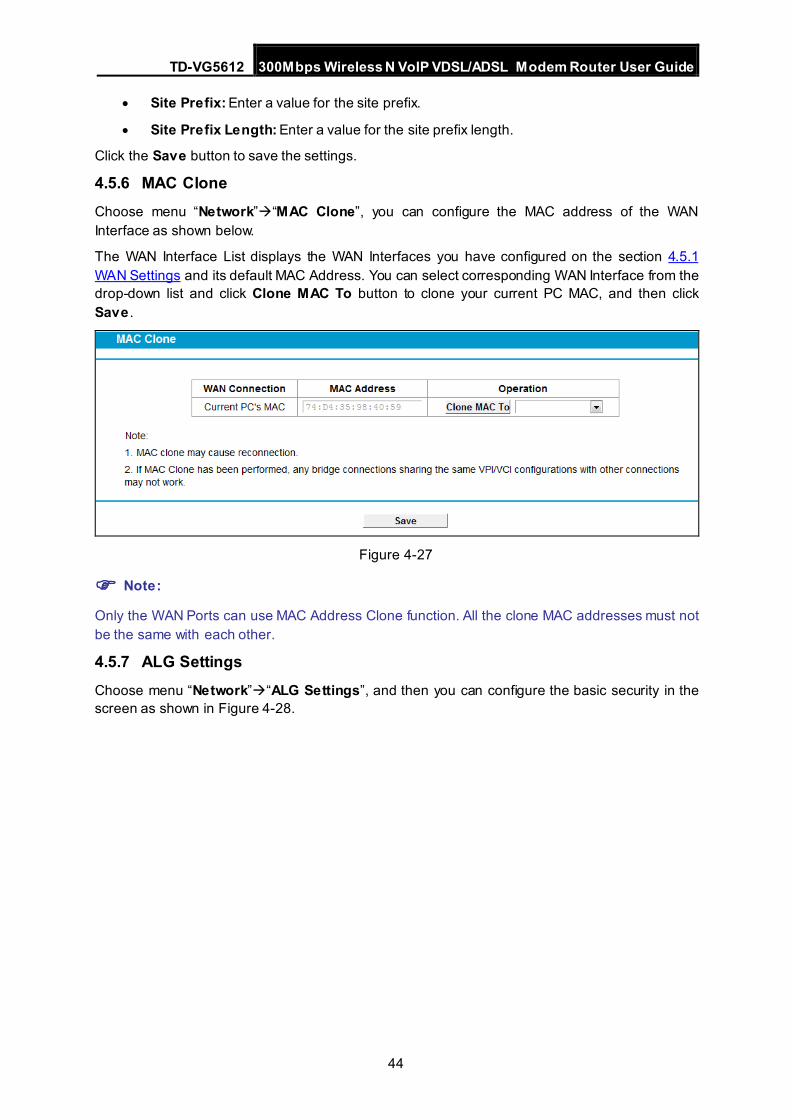
4.5.6 MAC Clone Choose menu “Network”“MAC Clone”, you can configure the MAC address of the WAN Interface as shown below.
The WAN Interface List displays the WAN Interfaces you have configured on the section 4.5.1 WAN Settings and its default MAC Address. You can select corresponding WAN Interface from the drop-down list and click Clone MAC To button to clone your current PC MAC, and then click Save .
Figure 4-27
Note:
Only the WAN Ports can use MAC Address Clone function. All the clone MAC addresses must not be the same with each other.
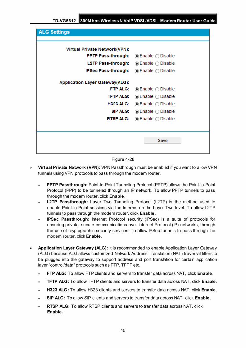
4.5.7 ALG Settings Choose menu “Network”“ALG Settings”, and then you can configure the basic security in the screen as shown in Figure 4-28.
TD-VG5612 300Mbps Wireless N VoIP VDSL/ADSL Modem Router User Guide
45
Figure 4-28
Virtual Private Network (VPN): VPN Passthrough must be enabled if you want to allow VPN tunnels using VPN protocols to pass through the modem router.
• PPTP Passthrough: Point-to-Point Tunneling Protocol (PPTP) allows the Point-to-Point Protocol (PPP) to be tunneled through an IP network. To allow PPTP tunnels to pass through the modem router, click Enable .
• L2TP Passthrough: Layer Two Tunneling Protocol (L2TP) is the method used to enable Point-to-Point sessions via the Internet on the Layer Two level. To allow L2TP tunnels to pass through the modem router, click Enable .
• IPSec Passthrough: Internet Protocol security (IPSec) is a suite of protocols for ensuring private, secure communications over Internet Protocol (IP) networks, through the use of cryptographic security services. To allow IPSec tunnels to pass through the modem router, click Enable .
Application Layer Gateway (ALG): It is recommended to enable Application Layer Gateway (ALG) because ALG allows customized Network Address Translation (NAT) traversal filters to be plugged into the gateway to support address and port translation for certain application layer "control/data" protocols such as FTP, TFTP etc.
• FTP ALG: To allow FTP clients and servers to transfer data across NAT, click Enable .
• TFTP ALG: To allow TFTP clients and servers to transfer data across NAT, click Enable .
• H323 ALG: To allow H323 clients and servers to transfer data across NAT, click Enable .
• SIP ALG: To allow SIP clients and servers to transfer data across NAT, click Enable .
• RTSP ALG: To allow RTSP clients and servers to transfer data across NAT, click Enable.
TD-VG5612 300Mbps Wireless N VoIP VDSL/ADSL Modem Router User Guide
46
Click the Save button to save your settings.
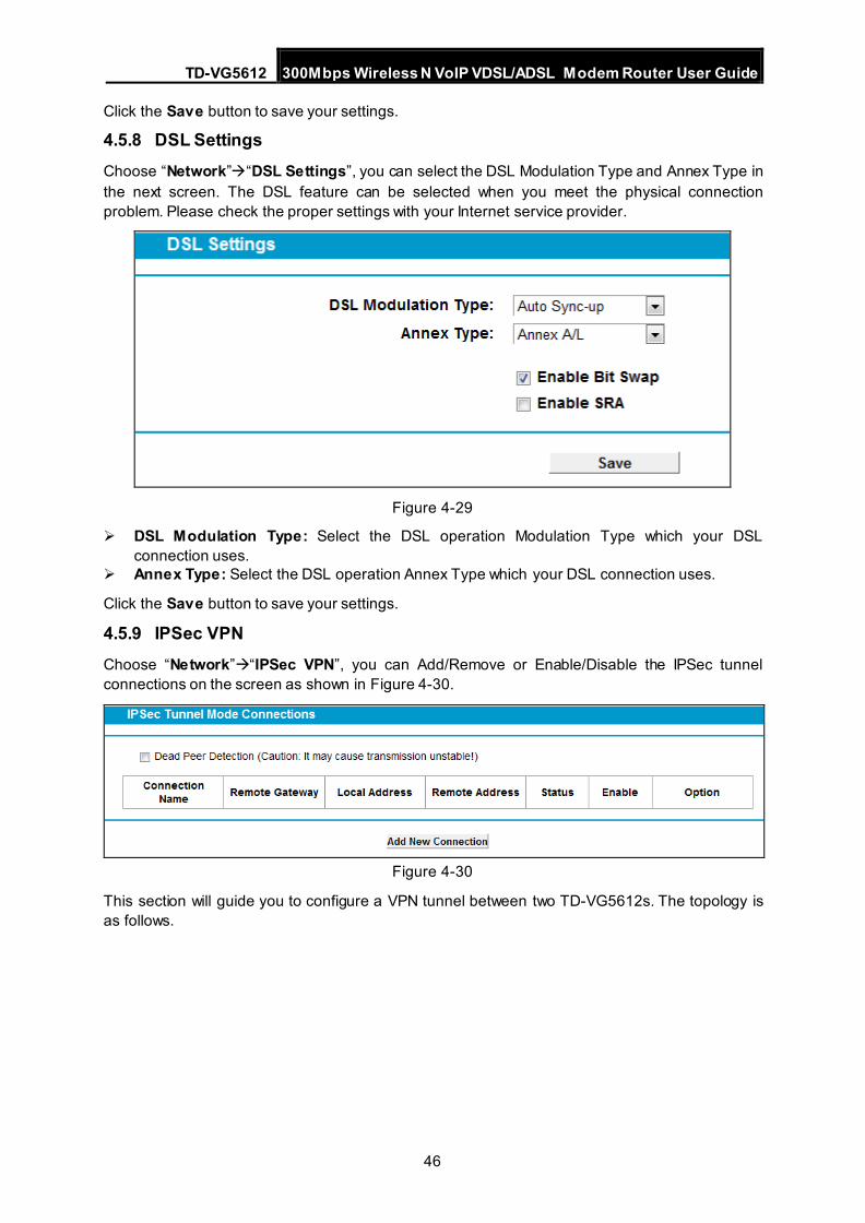
4.5.8 DSL Settings Choose “Network”“DSL Settings”, you can select the DSL Modulation Type and Annex Type in the next screen. The DSL feature can be selected when you meet the physical connection problem. Please check the proper settings with your Internet service provider.
Figure 4-29
DSL Modulation Type: Select the DSL operation Modulation Type which your DSL connection uses.
Annex Type: Select the DSL operation Annex Type which your DSL connection uses.
Click the Save button to save your settings.
4.5.9 IPSec VPN Choose “Network”“IPSec VPN”, you can Add/Remove or Enable/Disable the IPSec tunnel connections on the screen as shown in Figure 4-30.
Figure 4-30
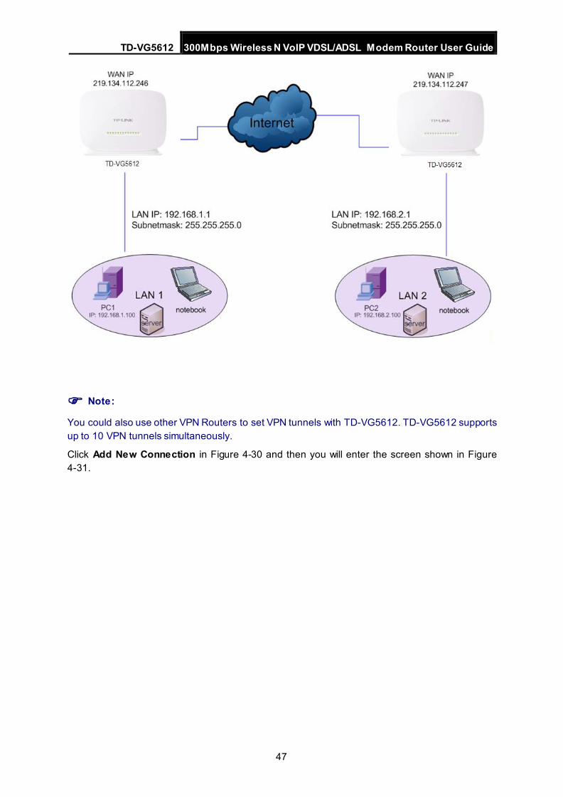
This section will guide you to configure a VPN tunnel between two TD-VG5612s. The topology is as follows.
TD-VG5612 300Mbps Wireless N VoIP VDSL/ADSL Modem Router User Guide
47
Note:
You could also use other VPN Routers to set VPN tunnels with TD-VG5612. TD-VG5612 supports up to 10 VPN tunnels simultaneously.
Click Add New Connection in Figure 4-30 and then you will enter the screen shown in Figure 4-31.
TD-VG5612 300Mbps Wireless N VoIP VDSL/ADSL Modem Router User Guide
48
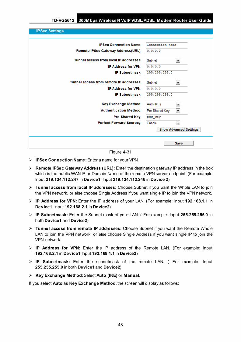
Figure 4-31
IPSec Connection Name: Enter a name for your VPN.
Remote IPSec Gateway Address (URL): Enter the destination gateway IP address in the box which is the public WAN IP or Domain Name of the remote VPN server endpoint. (For example: Input 219.134.112.247 in Device1, Input 219.134.112.246 in Device 2)
Tunnel access from local IP addresses: Choose Subnet if you want the Whole LAN to join the VPN network, or else choose Single Address if you want single IP to join the VPN network.
IP Address for VPN: Enter the IP address of your LAN. (For example: Input 192.168.1.1 in Device1, Input 192.168.2.1 in Device2)
IP Subnetmask: Enter the Subnet mask of your LAN. ( For example: Input 255.255.255.0 in both Device1 and Device2)
Tunnel access from remote IP addresses: Choose Subnet if you want the Remote Whole LAN to join the VPN network, or else choose Single Address if you want single IP to join the VPN network.
IP Address for VPN: Enter the IP address of the Remote LAN. (For example: Input 192.168.2.1 in Device1,Input 192.168.1.1 in Device2)
IP Subnetmask: Enter the subnetmask of the remote LAN. ( For example: Input 255.255.255.0 in both Device1 and Device2)
Key Exchange Method: Select Auto (IKE) or Manual.
If you select Auto as Key Exchange Method, the screen will display as follows:
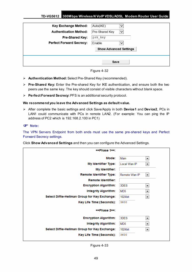
TD-VG5612 300Mbps Wireless N VoIP VDSL/ADSL Modem Router User Guide
49
Figure 4-32
Authentication Method: Select Pre-Shared Key (recommended).
Pre-Shared Key: Enter the Pre-shared Key for IKE authentication, and ensure both the two peers use the same key. The key should consist of visible characters without blank space.
Perfect Forward Secrecy: PFS is an additional security protocol.
We recommend you leave the Advanced Settings as default value.
After complete the basic settings and click Save/Apply in both Device1 and Device2, PCs in LAN1 could communicate with PCs in remote LAN2. (For example: You can ping the IP address of PC2 which is 192.168.2.100 in PC1)
Note: The VPN Servers Endpoint from both ends must use the same pre-shared keys and Perfect Forward Secrecy settings.
Click Show Advanced Settings and then you can configure the Advanced Settings.
Figure 4-33
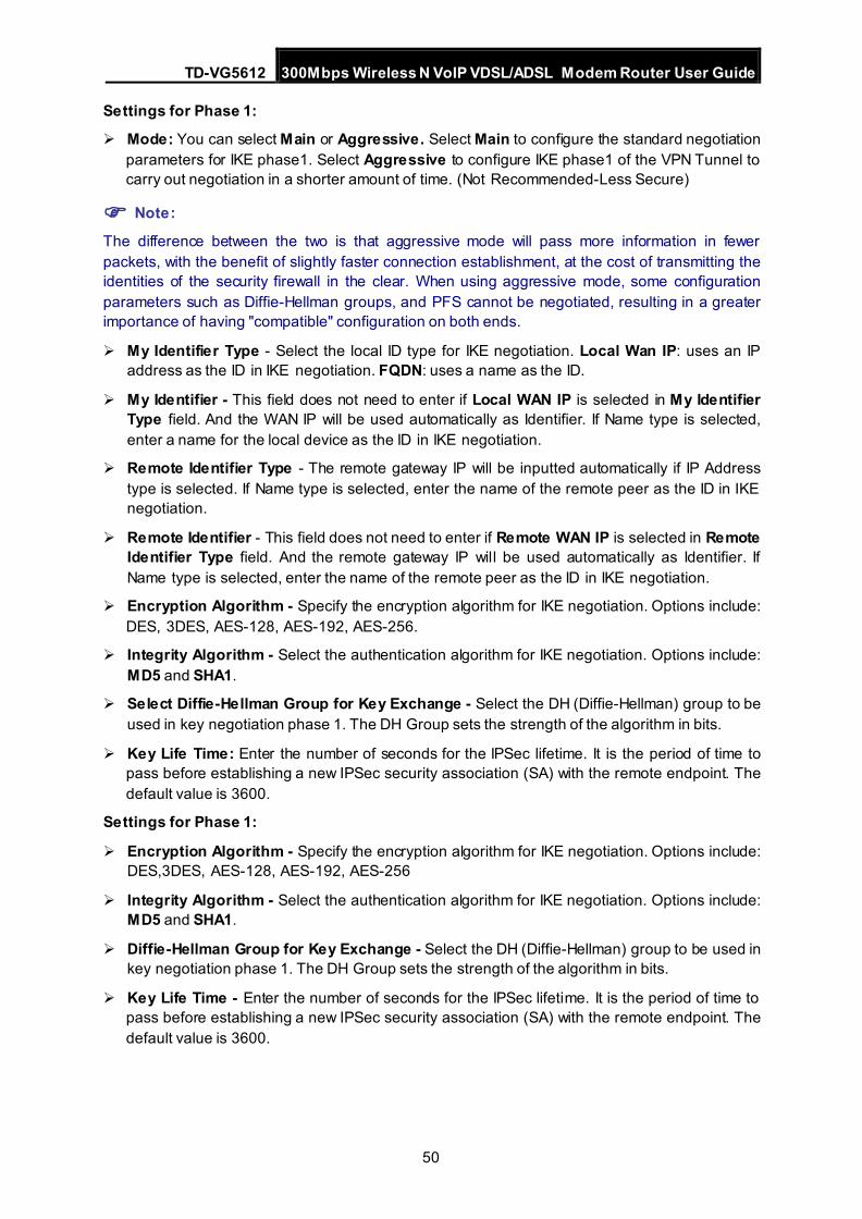
TD-VG5612 300Mbps Wireless N VoIP VDSL/ADSL Modem Router User Guide
50
Settings for Phase 1:
Mode: You can select Main or Aggressive. Select Main to configure the standard negotiation parameters for IKE phase1. Select Aggressive to configure IKE phase1 of the VPN Tunnel to carry out negotiation in a shorter amount of time. (Not Recommended-Less Secure)
Note: The difference between the two is that aggressive mode will pass more information in fewer packets, with the benefit of slightly faster connection establishment, at the cost of transmitting the identities of the security firewall in the clear. When using aggressive mode, some configuration parameters such as Diffie-Hellman groups, and PFS cannot be negotiated, resulting in a greater importance of having "compatible" configuration on both ends.
My Identifier Type - Select the local ID type for IKE negotiation. Local Wan IP: uses an IP address as the ID in IKE negotiation. FQDN: uses a name as the ID.
My Identifier - This field does not need to enter if Local WAN IP is selected in My Identifier Type field. And the WAN IP will be used automatically as Identifier. If Name type is selected, enter a name for the local device as the ID in IKE negotiation.
Remote Identifier Type - The remote gateway IP will be inputted automatically if IP Address type is selected. If Name type is selected, enter the name of the remote peer as the ID in IKE negotiation.
Remote Identifier - This field does not need to enter if Remote WAN IP is selected in Remote Identifier Type field. And the remote gateway IP will be used automatically as Identifier. If Name type is selected, enter the name of the remote peer as the ID in IKE negotiation.
Encryption Algorithm - Specify the encryption algorithm for IKE negotiation. Options include: DES, 3DES, AES-128, AES-192, AES-256.
Integrity Algorithm - Select the authentication algorithm for IKE negotiation. Options include: MD5 and SHA1.
Select Diffie-Hellman Group for Key Exchange - Select the DH (Diffie-Hellman) group to be used in key negotiation phase 1. The DH Group sets the strength of the algorithm in bits.
Key Life Time: Enter the number of seconds for the IPSec lifetime. It is the period of time to pass before establishing a new IPSec security association (SA) with the remote endpoint. The default value is 3600.
Settings for Phase 1:
Encryption Algorithm - Specify the encryption algorithm for IKE negotiation. Options include: DES,3DES, AES-128, AES-192, AES-256
Integrity Algorithm - Select the authentication algorithm for IKE negotiation. Options include: MD5 and SHA1.
Diffie-Hellman Group for Key Exchange - Select the DH (Diffie-Hellman) group to be used in key negotiation phase 1. The DH Group sets the strength of the algorithm in bits.
Key Life Time - Enter the number of seconds for the IPSec lifetime. It is the period of time to pass before establishing a new IPSec security association (SA) with the remote endpoint. The default value is 3600.
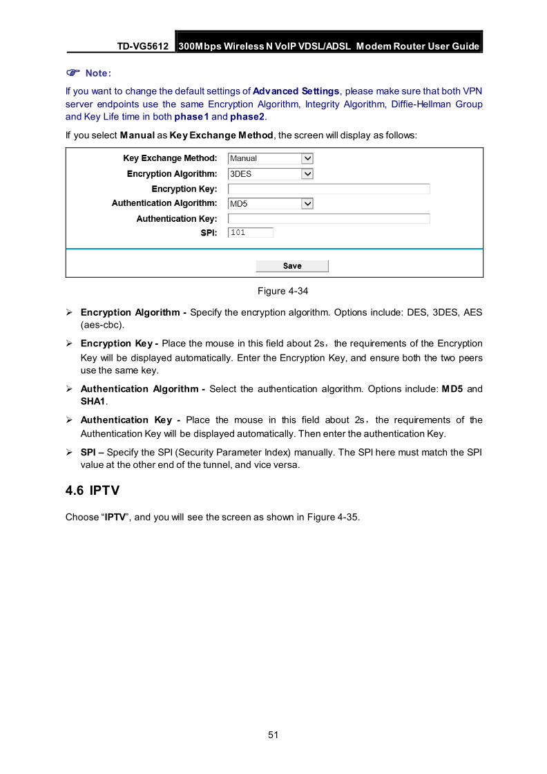
TD-VG5612 300Mbps Wireless N VoIP VDSL/ADSL Modem Router User Guide
51
Note: If you want to change the default settings of Advanced Settings, please make sure that both VPN server endpoints use the same Encryption Algorithm, Integrity Algorithm, Diffie-Hellman Group and Key Life time in both phase1 and phase2.
If you select Manual as Key Exchange Method, the screen will display as follows:
Figure 4-34
Encryption Algorithm - Specify the encryption algorithm. Options include: DES, 3DES, AES (aes-cbc).
Encryption Key - Place the mouse in this field about 2s,the requirements of the Encryption Key will be displayed automatically. Enter the Encryption Key, and ensure both the two peers use the same key.
Authentication Algorithm - Select the authentication algorithm. Options include: MD5 and SHA1.
Authentication Key - Place the mouse in this field about 2s,the requirements of the Authentication Key will be displayed automatically. Then enter the authentication Key.
SPI – Specify the SPI (Security Parameter Index) manually. The SPI here must match the SPI value at the other end of the tunnel, and vice versa.
4.6 IPTV
Choose “IPTV”, and you will see the screen as shown in Figure 4-35.
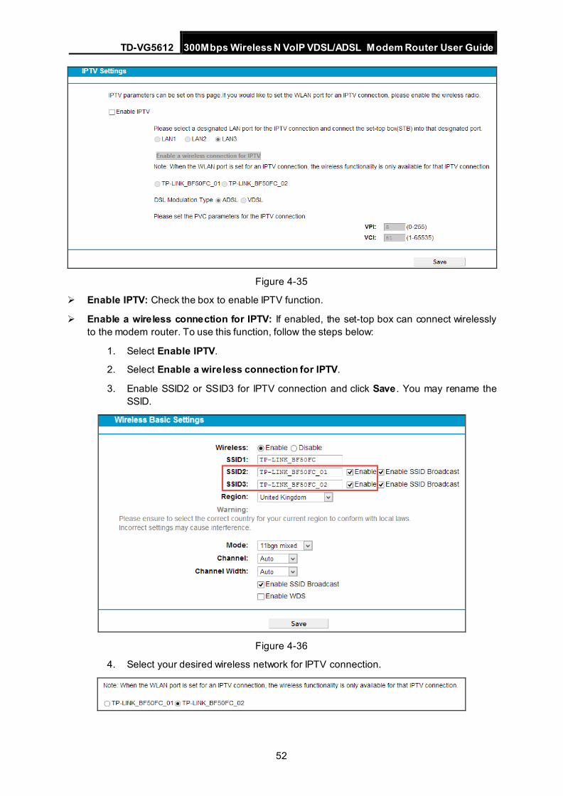
TD-VG5612 300Mbps Wireless N VoIP VDSL/ADSL Modem Router User Guide
52
Figure 4-35
Enable IPTV: Check the box to enable IPTV function.
Enable a wireless connection for IPTV: If enabled, the set-top box can connect wirelessly to the modem router. To use this function, follow the steps below:
1. Select Enable IPTV.
2. Select Enable a wireless connection for IPTV.
3. Enable SSID2 or SSID3 for IPTV connection and click Save . You may rename the SSID.
Figure 4-36
4. Select your desired wireless network for IPTV connection.
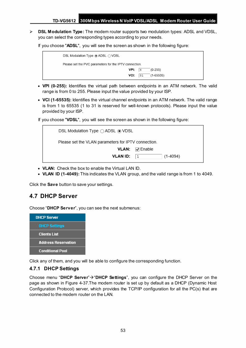
TD-VG5612 300Mbps Wireless N VoIP VDSL/ADSL Modem Router User Guide
53
DSL Modulation Type: The modem router supports two modulation types: ADSL and VDSL, you can select the corresponding types according to your needs.
If you choose "ADSL", you will see the screen as shown in the following figure:
• VPI (0-255): Identifies the virtual path between endpoints in an ATM network. The valid range is from 0 to 255. Please input the value provided by your ISP.
• VCI (1-65535): Identifies the virtual channel endpoints in an ATM network. The valid range is from 1 to 65535 (1 to 31 is reserved for well-known protocols). Please input the value provided by your ISP.
If you choose "VDSL", you will see the screen as shown in the following figure:
• VLAN: Check the box to enable the Virtual LAN ID. • VLAN ID (1-4049): This indicates the VLAN group, and the valid range is from 1 to 4049.
Click the Save button to save your settings.
4.7 DHCP Server
Choose “DHCP Server”, you can see the next submenus:
Click any of them, and you will be able to configure the corresponding function.
4.7.1 DHCP Settings Choose menu “DHCP Server”“DHCP Settings”, you can configure the DHCP Server on the page as shown in Figure 4-37.The modem router is set up by default as a DHCP (Dynamic Host Configuration Protocol) server, which provides the TCP/IP configuration for all the PC(s) that are connected to the modem router on the LAN.
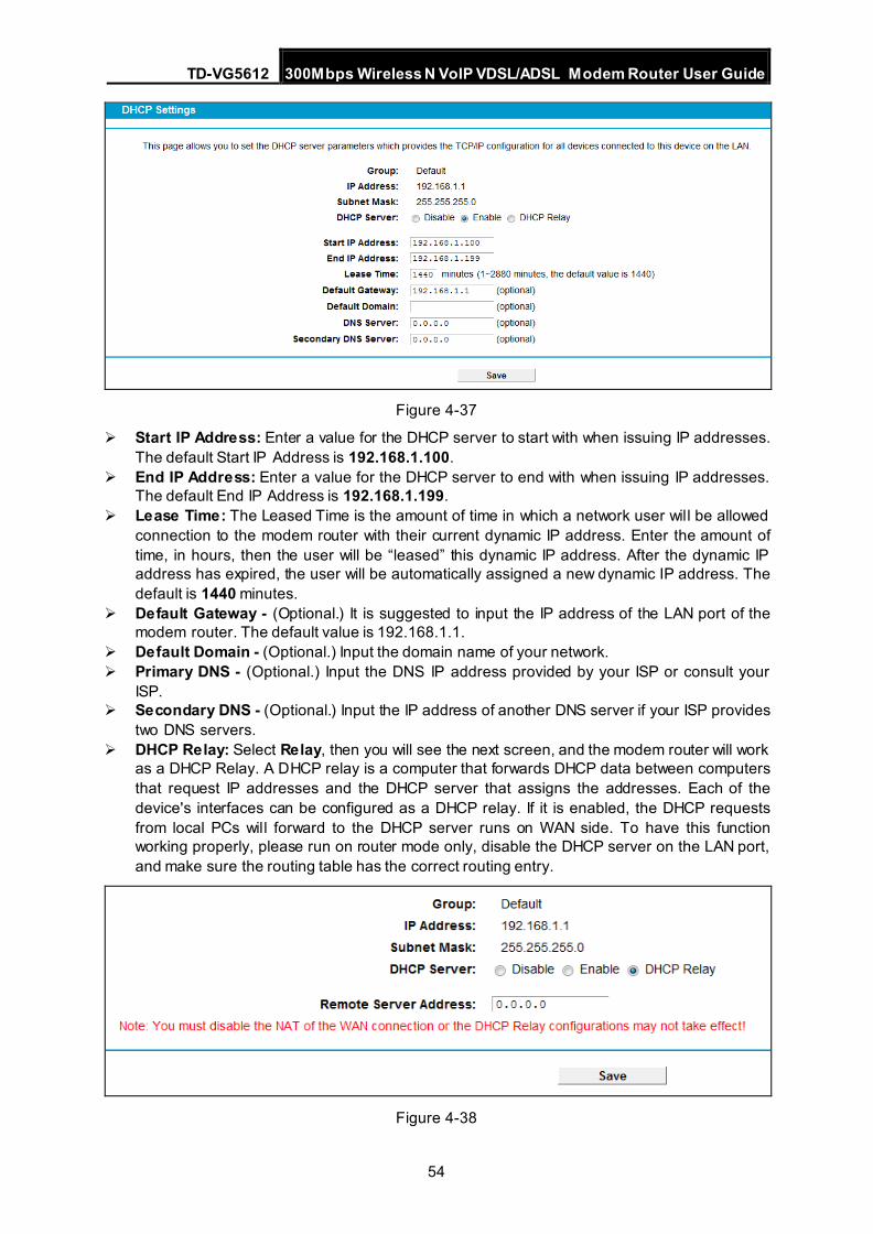
TD-VG5612 300Mbps Wireless N VoIP VDSL/ADSL Modem Router User Guide
54
Figure 4-37
Start IP Address: Enter a value for the DHCP server to start with when issuing IP addresses. The default Start IP Address is 192.168.1.100.
End IP Address: Enter a value for the DHCP server to end with when issuing IP addresses. The default End IP Address is 192.168.1.199.
Lease Time: The Leased Time is the amount of time in which a network user will be allowed connection to the modem router with their current dynamic IP address. Enter the amount of time, in hours, then the user will be “leased” this dynamic IP address. After the dynamic IP address has expired, the user will be automatically assigned a new dynamic IP address. The default is 1440 minutes.
Default Gateway - (Optional.) It is suggested to input the IP address of the LAN port of the modem router. The default value is 192.168.1.1.
Default Domain - (Optional.) Input the domain name of your network. Primary DNS - (Optional.) Input the DNS IP address provided by your ISP or consult your
ISP. Secondary DNS - (Optional.) Input the IP address of another DNS server if your ISP provides
two DNS servers. DHCP Relay: Select Relay, then you will see the next screen, and the modem router will work
as a DHCP Relay. A DHCP relay is a computer that forwards DHCP data between computers that request IP addresses and the DHCP server that assigns the addresses. Each of the device's interfaces can be configured as a DHCP relay. If it is enabled, the DHCP requests from local PCs will forward to the DHCP server runs on WAN side. To have this function working properly, please run on router mode only, disable the DHCP server on the LAN port, and make sure the routing table has the correct routing entry.
Figure 4-38
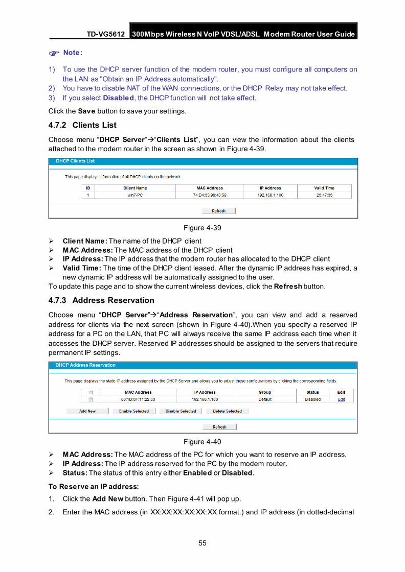
TD-VG5612 300Mbps Wireless N VoIP VDSL/ADSL Modem Router User Guide
55
Note:
1) To use the DHCP server function of the modem router, you must configure all computers on the LAN as "Obtain an IP Address automatically".
2) You have to disable NAT of the WAN connections, or the DHCP Relay may not take effect. 3) If you select Disabled, the DHCP function will not take effect.
Click the Save button to save your settings.
4.7.2 Clients List Choose menu “DHCP Server”“Clients List”, you can view the information about the clients attached to the modem router in the screen as shown in Figure 4-39.
Figure 4-39
Client Name: The name of the DHCP client MAC Address: The MAC address of the DHCP client IP Address: The IP address that the modem router has allocated to the DHCP client Valid Time: The time of the DHCP client leased. After the dynamic IP address has expired, a
new dynamic IP address will be automatically assigned to the user. To update this page and to show the current wireless devices, click the Refresh button.
4.7.3 Address Reservation Choose menu “DHCP Server”“Address Reservation”, you can view and add a reserved address for clients via the next screen (shown in Figure 4-40).When you specify a reserved IP address for a PC on the LAN, that PC will always receive the same IP address each time when it accesses the DHCP server. Reserved IP addresses should be assigned to the servers that require permanent IP settings.
Figure 4-40
MAC Address: The MAC address of the PC for which you want to reserve an IP address. IP Address: The IP address reserved for the PC by the modem router. Status: The status of this entry either Enabled or Disabled.
To Reserve an IP address: 1. Click the Add New button. Then Figure 4-41 will pop up.
2. Enter the MAC address (in XX:XX:XX:XX:XX:XX format.) and IP address (in dotted-decimal
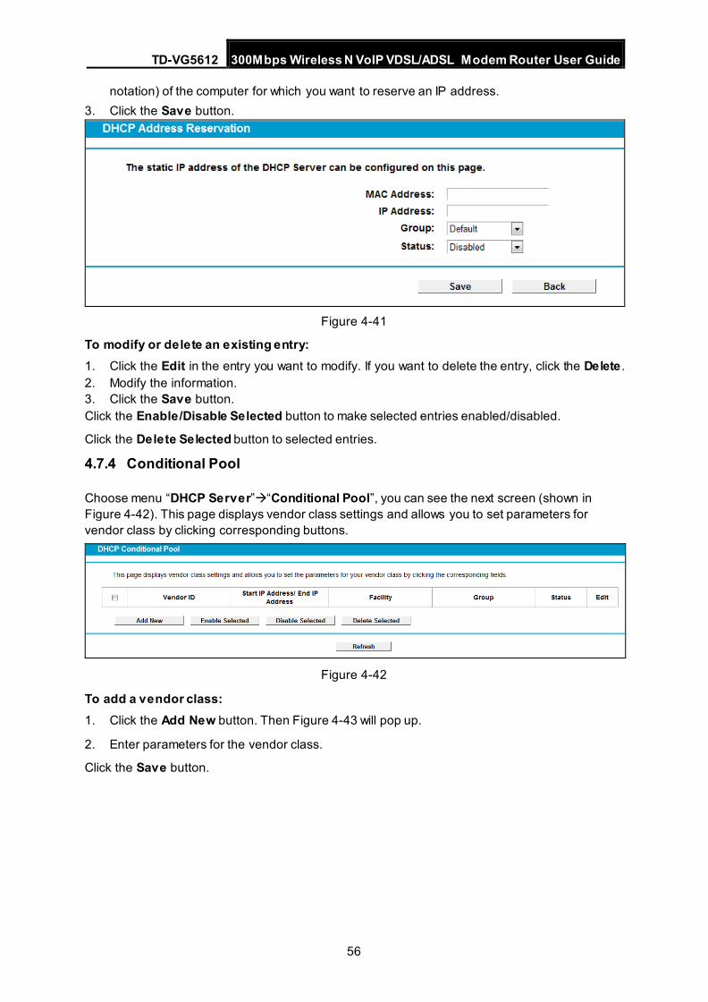
TD-VG5612 300Mbps Wireless N VoIP VDSL/ADSL Modem Router User Guide
56
notation) of the computer for which you want to reserve an IP address. 3. Click the Save button.
Figure 4-41
To modify or delete an existing entry: 1. Click the Edit in the entry you want to modify. If you want to delete the entry, click the Delete . 2. Modify the information. 3. Click the Save button. Click the Enable/Disable Selected button to make selected entries enabled/disabled.
Click the Delete Selected button to selected entries.
4.7.4 Conditional Pool
Choose menu “DHCP Server”“Conditional Pool”, you can see the next screen (shown in Figure 4-42). This page displays vendor class settings and allows you to set parameters for vendor class by clicking corresponding buttons.
Figure 4-42
To add a vendor class: 1. Click the Add New button. Then Figure 4-43 will pop up.
2. Enter parameters for the vendor class.
Click the Save button.
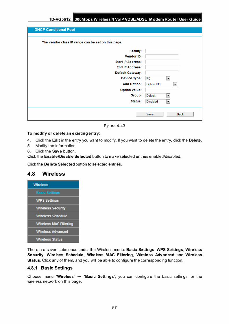
TD-VG5612 300Mbps Wireless N VoIP VDSL/ADSL Modem Router User Guide
57
Figure 4-43
To modify or delete an existing entry: 4. Click the Edit in the entry you want to modify. If you want to delete the entry, click the Delete . 5. Modify the information. 6. Click the Save button. Click the Enable/Disable Selected button to make selected entries enabled/disabled.
Click the Delete Selected button to selected entries.
4.8 Wireless
There are seven submenus under the Wireless menu: Basic Settings, WPS Settings, Wireless Security, Wireless Schedule , Wireless MAC Filtering, Wireless Advanced and Wireless Status. Click any of them, and you will be able to configure the corresponding function.
4.8.1 Basic Settings
Choose menu “Wireless” → “Basic Settings”, you can configure the basic settings for the wireless network on this page.
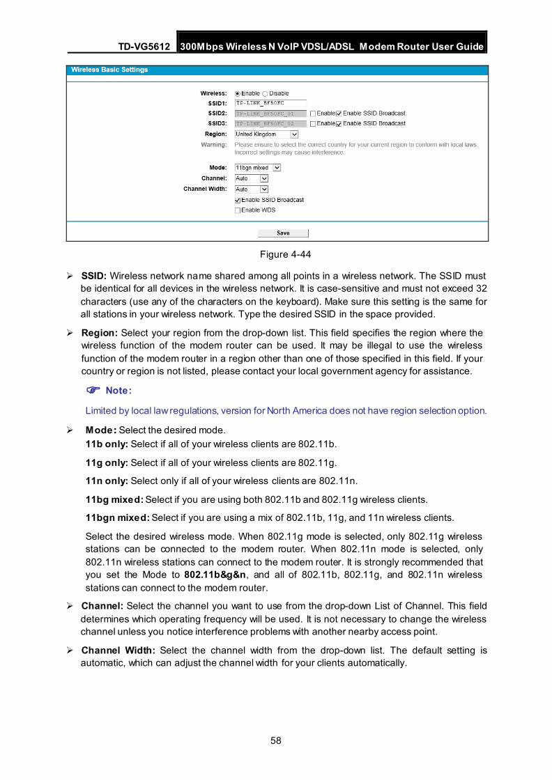
TD-VG5612 300Mbps Wireless N VoIP VDSL/ADSL Modem Router User Guide
58
Figure 4-44
SSID: Wireless network name shared among all points in a wireless network. The SSID must be identical for all devices in the wireless network. It is case-sensitive and must not exceed 32 characters (use any of the characters on the keyboard). Make sure this setting is the same for all stations in your wireless network. Type the desired SSID in the space provided.
Region: Select your region from the drop-down list. This field specifies the region where the wireless function of the modem router can be used. It may be illegal to use the wireless function of the modem router in a region other than one of those specified in this field. If your country or region is not listed, please contact your local government agency for assistance.
Note: Limited by local law regulations, version for North America does not have region selection option.
Mode: Select the desired mode. 11b only: Select if all of your wireless clients are 802.11b.
11g only: Select if all of your wireless clients are 802.11g.
11n only: Select only if all of your wireless clients are 802.11n.
11bg mixed: Select if you are using both 802.11b and 802.11g wireless clients.
11bgn mixed: Select if you are using a mix of 802.11b, 11g, and 11n wireless clients.
Select the desired wireless mode. When 802.11g mode is selected, only 802.11g wireless stations can be connected to the modem router. When 802.11n mode is selected, only 802.11n wireless stations can connect to the modem router. It is strongly recommended that you set the Mode to 802.11b&g&n, and all of 802.11b, 802.11g, and 802.11n wireless stations can connect to the modem router.
Channel: Select the channel you want to use from the drop-down List of Channel. This field determines which operating frequency will be used. It is not necessary to change the wireless channel unless you notice interference problems with another nearby access point.
Channel Width: Select the channel width from the drop-down list. The default setting is automatic, which can adjust the channel width for your clients automatically.
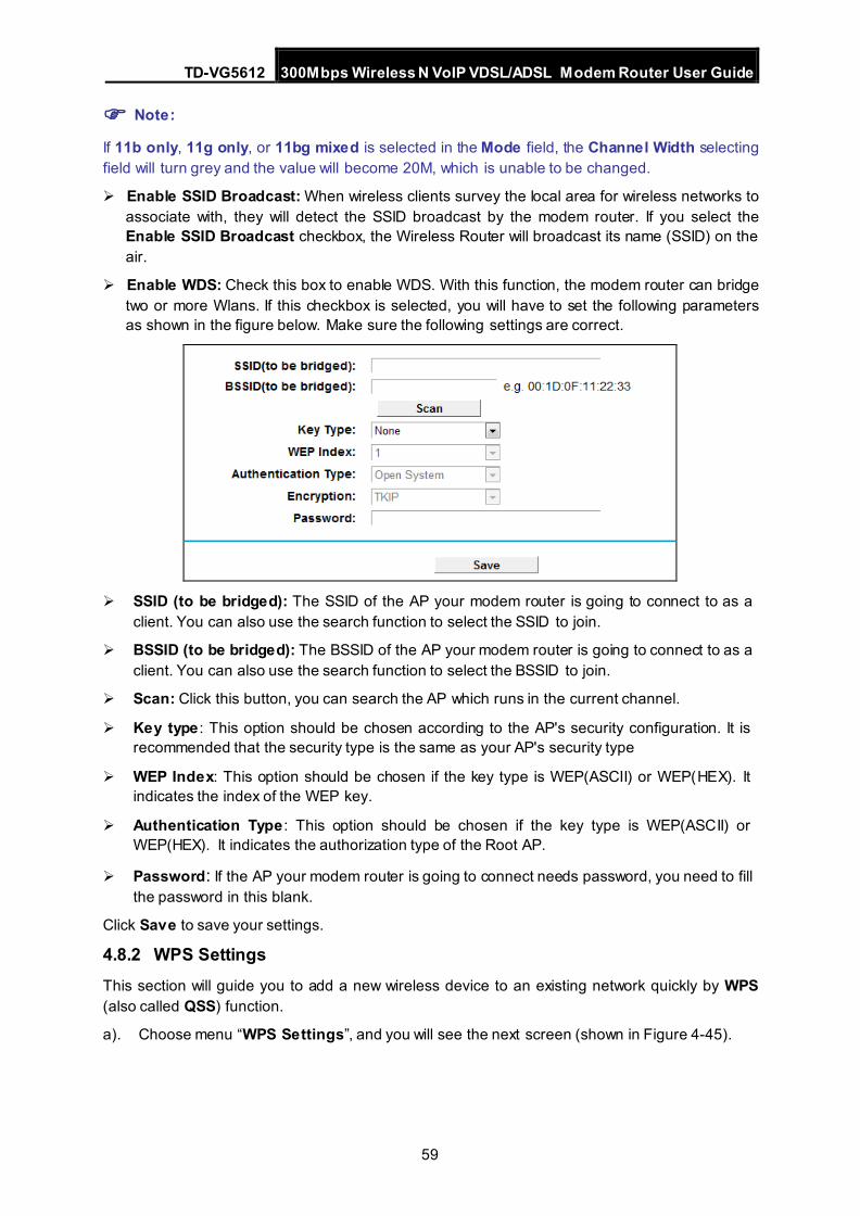
TD-VG5612 300Mbps Wireless N VoIP VDSL/ADSL Modem Router User Guide
59
Note:
If 11b only, 11g only, or 11bg mixed is selected in the Mode field, the Channel Width selecting field will turn grey and the value will become 20M, which is unable to be changed.
Enable SSID Broadcast: When wireless clients survey the local area for wireless networks to associate with, they will detect the SSID broadcast by the modem router. If you select the Enable SSID Broadcast checkbox, the Wireless Router will broadcast its name (SSID) on the air.
Enable WDS: Check this box to enable WDS. With this function, the modem router can bridge two or more Wlans. If this checkbox is selected, you will have to set the following parameters as shown in the figure below. Make sure the following settings are correct.
SSID (to be bridged): The SSID of the AP your modem router is going to connect to as a
client. You can also use the search function to select the SSID to join.
BSSID (to be bridged): The BSSID of the AP your modem router is going to connect to as a client. You can also use the search function to select the BSSID to join.
Scan: Click this button, you can search the AP which runs in the current channel.
Key type : This option should be chosen according to the AP's security configuration. It is recommended that the security type is the same as your AP's security type
WEP Index: This option should be chosen if the key type is WEP(ASCII) or WEP(HEX). It indicates the index of the WEP key.
Authentication Type : This option should be chosen if the key type is WEP(ASCII) or WEP(HEX). It indicates the authorization type of the Root AP.
Password: If the AP your modem router is going to connect needs password, you need to fill the password in this blank.
Click Save to save your settings.
4.8.2 WPS Settings This section will guide you to add a new wireless device to an existing network quickly by WPS (also called QSS) function.
a). Choose menu “WPS Settings”, and you will see the next screen (shown in Figure 4-45).
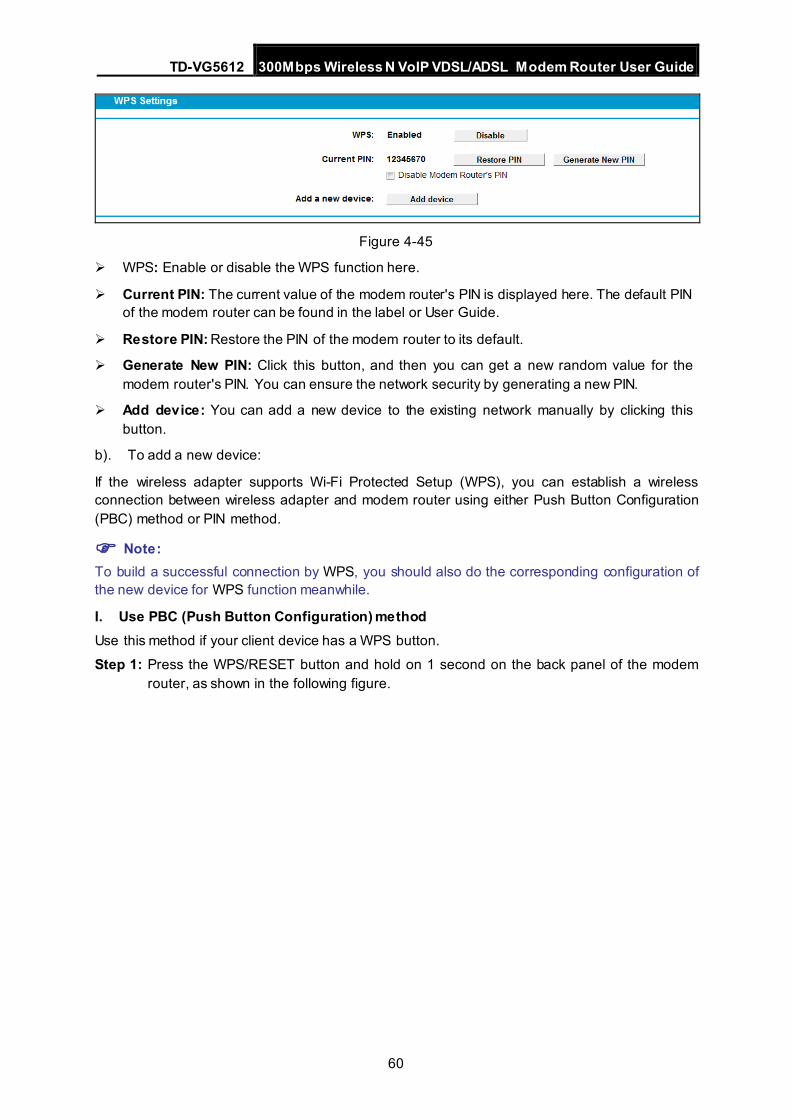
TD-VG5612 300Mbps Wireless N VoIP VDSL/ADSL Modem Router User Guide
60
Figure 4-45
WPS: Enable or disable the WPS function here.
Current PIN: The current value of the modem router's PIN is displayed here. The default PIN of the modem router can be found in the label or User Guide.
Restore PIN: Restore the PIN of the modem router to its default.
Generate New PIN: Click this button, and then you can get a new random value for the modem router's PIN. You can ensure the network security by generating a new PIN.
Add device: You can add a new device to the existing network manually by clicking this button.
b). To add a new device:
If the wireless adapter supports Wi-Fi Protected Setup (WPS), you can establish a wireless connection between wireless adapter and modem router using either Push Button Configuration (PBC) method or PIN method.
Note: To build a successful connection by WPS, you should also do the corresponding configuration of the new device for WPS function meanwhile.
I. Use PBC (Push Button Configuration) method Use this method if your client device has a WPS button.
Step 1: Press the WPS/RESET button and hold on 1 second on the back panel of the modem router, as shown in the following figure.
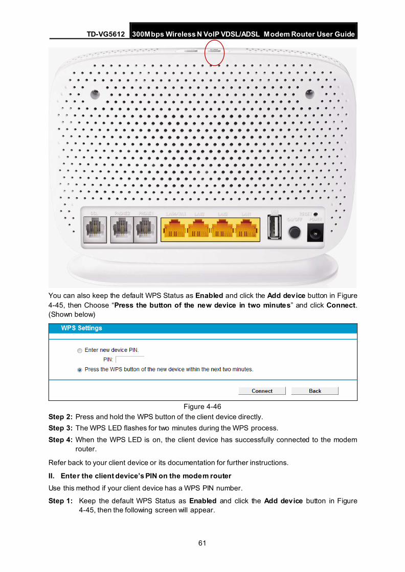
TD-VG5612 300Mbps Wireless N VoIP VDSL/ADSL Modem Router User Guide
61
You can also keep the default WPS Status as Enabled and click the Add device button in Figure 4-45, then Choose “Press the button of the new device in two minutes” and click Connect. (Shown below)
Figure 4-46
Step 2: Press and hold the WPS button of the client device directly. Step 3: The WPS LED flashes for two minutes during the WPS process. Step 4: When the WPS LED is on, the client device has successfully connected to the modem
router.
Refer back to your client device or its documentation for further instructions.
II. Enter the client device’s PIN on the modem router Use this method if your client device has a WPS PIN number.
Step 1: Keep the default WPS Status as Enabled and click the Add device button in Figure 4-45, then the following screen will appear.
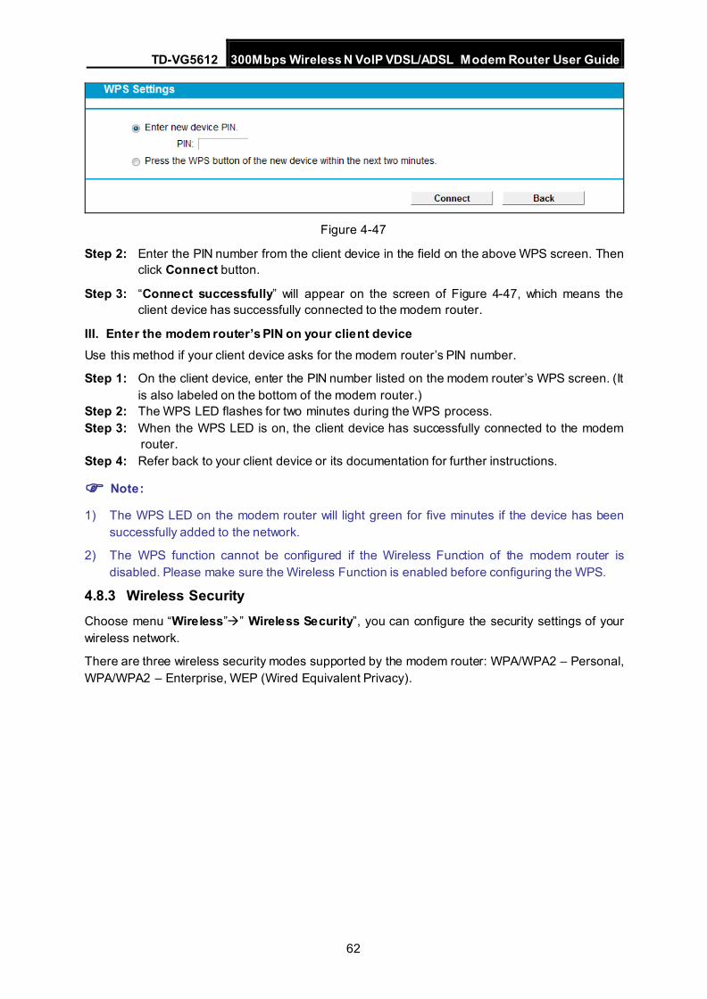
TD-VG5612 300Mbps Wireless N VoIP VDSL/ADSL Modem Router User Guide
62
Figure 4-47
Step 2: Enter the PIN number from the client device in the field on the above WPS screen. Then click Connect button.
Step 3: “Connect successfully” will appear on the screen of Figure 4-47, which means the client device has successfully connected to the modem router.
III. Enter the modem router’s PIN on your client device Use this method if your client device asks for the modem router’s PIN number.
Step 1: On the client device, enter the PIN number listed on the modem router’s WPS screen. (It is also labeled on the bottom of the modem router.)
Step 2: The WPS LED flashes for two minutes during the WPS process. Step 3: When the WPS LED is on, the client device has successfully connected to the modem
router. Step 4: Refer back to your client device or its documentation for further instructions.
Note:
1) The WPS LED on the modem router will light green for five minutes if the device has been successfully added to the network.
2) The WPS function cannot be configured if the Wireless Function of the modem router is disabled. Please make sure the Wireless Function is enabled before configuring the WPS.
4.8.3 Wireless Security Choose menu “Wireless”” Wireless Security”, you can configure the security settings of your wireless network.
There are three wireless security modes supported by the modem router: WPA/WPA2 – Personal, WPA/WPA2 – Enterprise, WEP (Wired Equivalent Privacy).
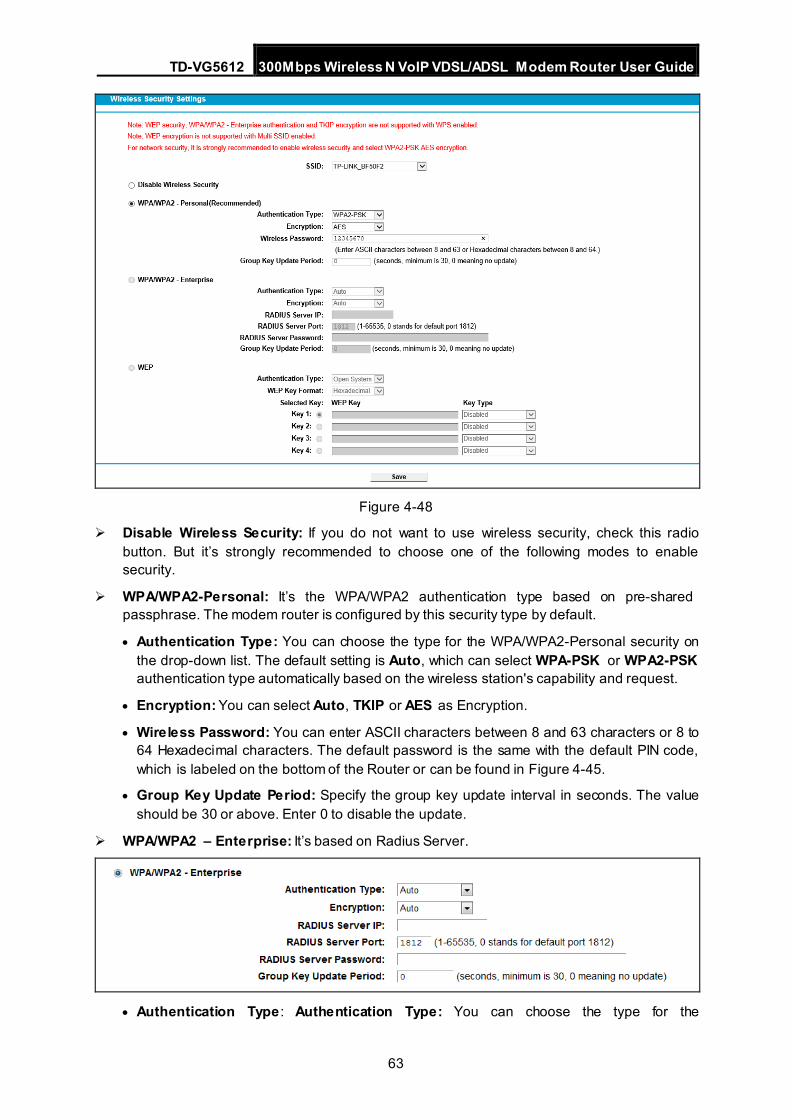
TD-VG5612 300Mbps Wireless N VoIP VDSL/ADSL Modem Router User Guide
63
Figure 4-48
Disable Wireless Security: If you do not want to use wireless security, check this radio button. But it’s strongly recommended to choose one of the following modes to enable security.
WPA/WPA2-Personal: It’s the WPA/WPA2 authentication type based on pre-shared passphrase. The modem router is configured by this security type by default.
• Authentication Type: You can choose the type for the WPA/WPA2-Personal security on the drop-down list. The default setting is Auto, which can select WPA-PSK or WPA2-PSK authentication type automatically based on the wireless station's capability and request.
• Encryption: You can select Auto, TKIP or AES as Encryption.
• Wireless Password: You can enter ASCII characters between 8 and 63 characters or 8 to 64 Hexadecimal characters. The default password is the same with the default PIN code, which is labeled on the bottom of the Router or can be found in Figure 4-45.
• Group Key Update Period: Specify the group key update interval in seconds. The value should be 30 or above. Enter 0 to disable the update.
WPA/WPA2 – Enterprise: It’s based on Radius Server.
• Authentication Type : Authentication Type: You can choose the type for the
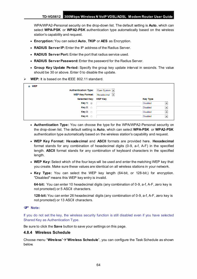
TD-VG5612 300Mbps Wireless N VoIP VDSL/ADSL Modem Router User Guide
64
WPA/WPA2-Personal security on the drop-down list. The default setting is Auto, which can select WPA-PSK or WPA2-PSK authentication type automatically based on the wireless station's capability and request.
• Encryption: You can select Auto, TKIP or AES as Encryption.
• RADIUS Server IP: Enter the IP address of the Radius Server.
• RADIUS Server Port: Enter the port that radius service used.
• RADIUS Server Password: Enter the password for the Radius Server.
• Group Key Update Period: Specify the group key update interval in seconds. The value should be 30 or above. Enter 0 to disable the update.
WEP: It is based on the IEEE 802.11 standard.
• Authentication Type: You can choose the type for the WPA/WPA2-Personal security on
the drop-down list. The default setting is Auto, which can select WPA-PSK or WPA2-PSK authentication type automatically based on the wireless station's capability and request.
• WEP Key Format: Hexadecimal and ASCII formats are provided here. Hexadecimal format stands for any combination of hexadecimal digits (0-9, a-f, A-F) in the specified length. ASCII format stands for any combination of keyboard characters in the specified length.
• WEP Key: Select which of the four keys will be used and enter the matching WEP key that you create. Make sure these values are identical on all wireless stations in your network.
• Key Type: You can select the WEP key length (64-bit, or 128-bit.) for encryption. "Disabled" means this WEP key entry is invalid.
64-bit: You can enter 10 hexadecimal digits (any combination of 0-9, a-f, A-F, zero key is not promoted) or 5 ASCII characters.
128-bit: You can enter 26 hexadecimal digits (any combination of 0-9, a-f, A-F, zero key is not promoted) or 13 ASCII characters.
Note:
If you do not set the key, the wireless security function is still disabled even if you have selected Shared Key as Authentication Type.
Be sure to click the Save button to save your settings on this page.
4.8.4 Wireless Schedule
Choose menu “Wireless”“Wireless Schedule”, you can configure the Task Schedule as shown below.
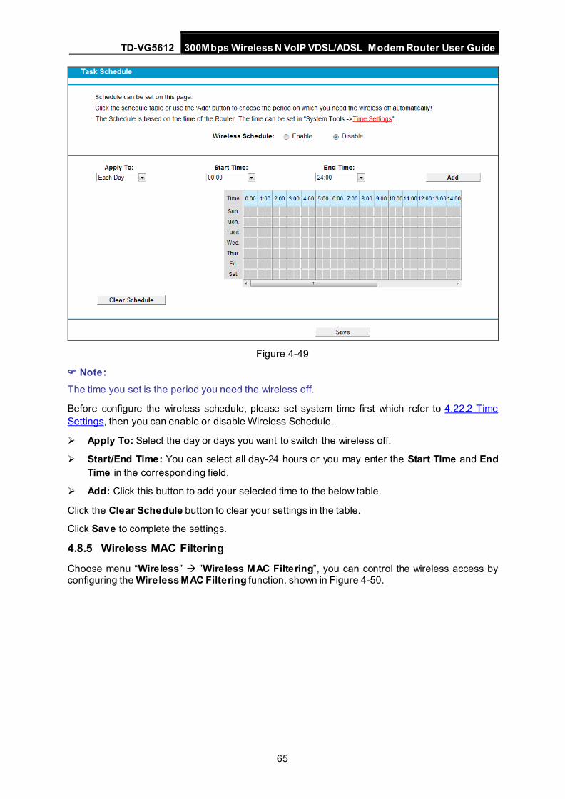
TD-VG5612 300Mbps Wireless N VoIP VDSL/ADSL Modem Router User Guide
65
Figure 4-49
Note: The time you set is the period you need the wireless off.
Before configure the wireless schedule, please set system time first which refer to 4.22.2 Time Settings, then you can enable or disable Wireless Schedule.
Apply To: Select the day or days you want to switch the wireless off.
Start/End Time: You can select all day-24 hours or you may enter the Start Time and End Time in the corresponding field.
Add: Click this button to add your selected time to the below table.
Click the Clear Schedule button to clear your settings in the table.
Click Save to complete the settings.
4.8.5 Wireless MAC Filtering Choose menu “Wireless” ”Wireless MAC Filtering”, you can control the wireless access by configuring the Wireless MAC Filtering function, shown in Figure 4-50.
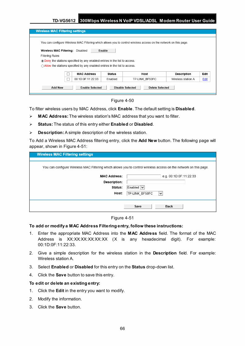
TD-VG5612 300Mbps Wireless N VoIP VDSL/ADSL Modem Router User Guide
66
Figure 4-50
To filter wireless users by MAC Address, click Enable . The default setting is Disabled.
MAC Address: The wireless station's MAC address that you want to filter.
Status: The status of this entry either Enabled or Disabled.
Description: A simple description of the wireless station.
To Add a Wireless MAC Address filtering entry, click the Add New button. The following page will appear, shown in Figure 4-51:
Figure 4-51
To add or modify a MAC Address Filtering entry, follow these instructions: 1. Enter the appropriate MAC Address into the MAC Address field. The format of the MAC
Address is XX:XX:XX:XX:XX:XX (X is any hexadecimal digit). For example: 00:1D:0F:11:22:33.
2. Give a simple description for the wireless station in the Description field. For example: Wireless station A.
3. Select Enabled or Disabled for this entry on the Status drop-down list.
4. Click the Save button to save this entry.
To edit or delete an existing entry: 1. Click the Edit in the entry you want to modify.
2. Modify the information.
3. Click the Save button.
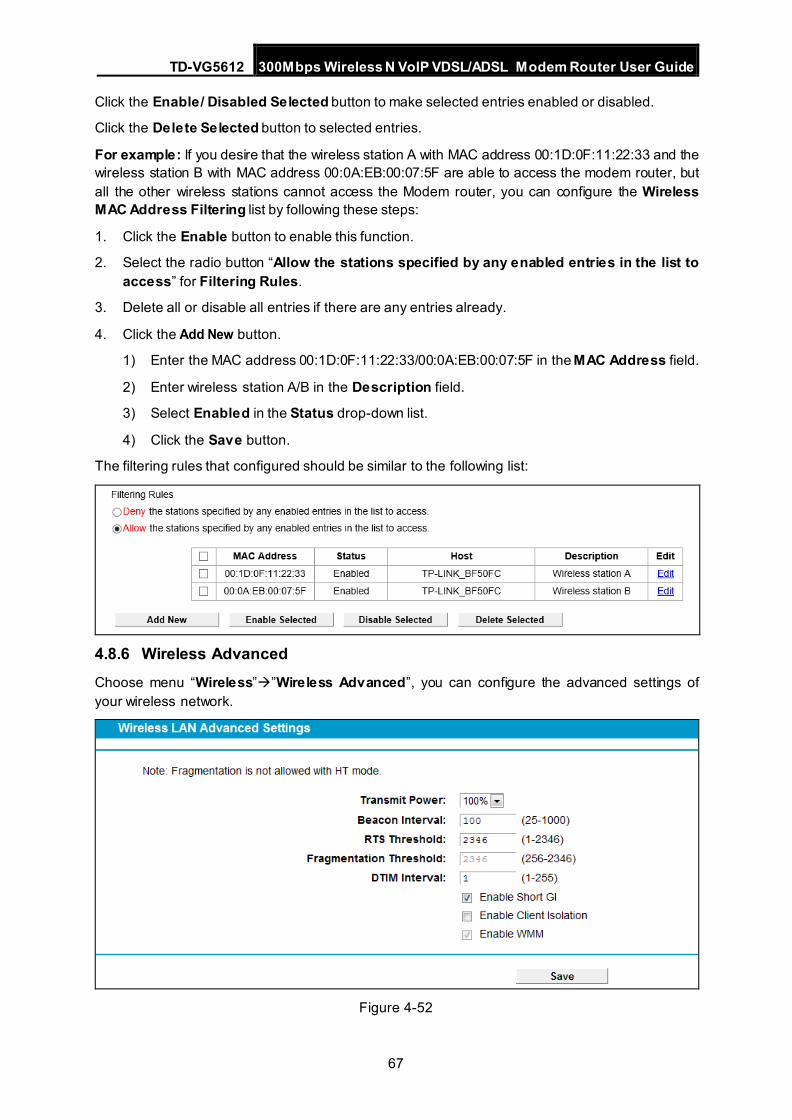
TD-VG5612 300Mbps Wireless N VoIP VDSL/ADSL Modem Router User Guide
67
Click the Enable/ Disabled Selected button to make selected entries enabled or disabled.
Click the Delete Selected button to selected entries.
For example: If you desire that the wireless station A with MAC address 00:1D:0F:11:22:33 and the wireless station B with MAC address 00:0A:EB:00:07:5F are able to access the modem router, but all the other wireless stations cannot access the Modem router, you can configure the Wireless MAC Address Filtering list by following these steps:
1. Click the Enable button to enable this function.
2. Select the radio button “Allow the stations specified by any enabled entries in the list to access” for Filtering Rules.
3. Delete all or disable all entries if there are any entries already.
4. Click the Add New button.
1) Enter the MAC address 00:1D:0F:11:22:33/00:0A:EB:00:07:5F in the MAC Address field.
2) Enter wireless station A/B in the Description field.
3) Select Enabled in the Status drop-down list.
4) Click the Save button.
The filtering rules that configured should be similar to the following list:
4.8.6 Wireless Advanced Choose menu “Wireless””Wireless Advanced”, you can configure the advanced settings of your wireless network.
Figure 4-52
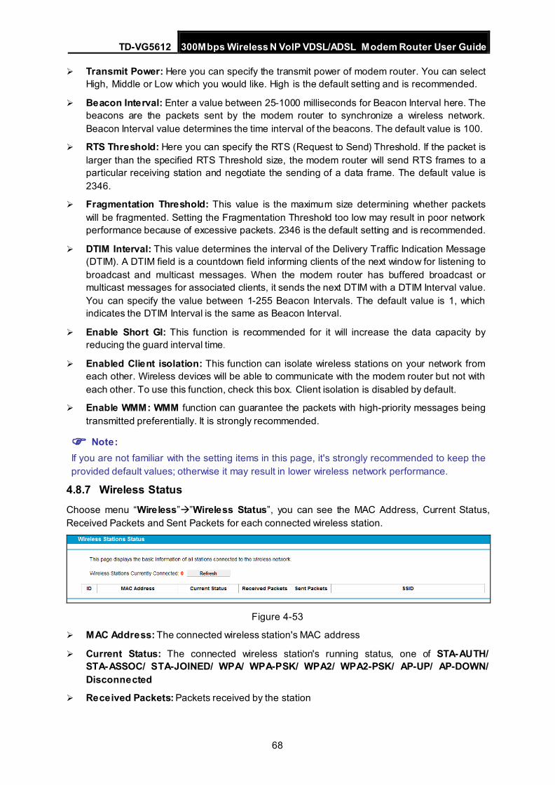
TD-VG5612 300Mbps Wireless N VoIP VDSL/ADSL Modem Router User Guide
68
Transmit Power: Here you can specify the transmit power of modem router. You can select High, Middle or Low which you would like. High is the default setting and is recommended.
Beacon Interval: Enter a value between 25-1000 milliseconds for Beacon Interval here. The beacons are the packets sent by the modem router to synchronize a wireless network. Beacon Interval value determines the time interval of the beacons. The default value is 100.
RTS Threshold: Here you can specify the RTS (Request to Send) Threshold. If the packet is larger than the specified RTS Threshold size, the modem router will send RTS frames to a particular receiving station and negotiate the sending of a data frame. The default value is 2346.
Fragmentation Threshold: This value is the maximum size determining whether packets will be fragmented. Setting the Fragmentation Threshold too low may result in poor network performance because of excessive packets. 2346 is the default setting and is recommended.
DTIM Interval: This value determines the interval of the Delivery Traffic Indication Message (DTIM). A DTIM field is a countdown field informing clients of the next window for listening to broadcast and multicast messages. When the modem router has buffered broadcast or multicast messages for associated clients, it sends the next DTIM with a DTIM Interval value. You can specify the value between 1-255 Beacon Intervals. The default value is 1, which indicates the DTIM Interval is the same as Beacon Interval.
Enable Short GI: This function is recommended for it will increase the data capacity by reducing the guard interval time.
Enabled Client isolation: This function can isolate wireless stations on your network from each other. Wireless devices will be able to communicate with the modem router but not with each other. To use this function, check this box. Client isolation is disabled by default.
Enable WMM: WMM function can guarantee the packets with high-priority messages being transmitted preferentially. It is strongly recommended.
Note: If you are not familiar with the setting items in this page, it's strongly recommended to keep the provided default values; otherwise it may result in lower wireless network performance.
4.8.7 Wireless Status Choose menu “Wireless””Wireless Status”, you can see the MAC Address, Current Status, Received Packets and Sent Packets for each connected wireless station.
Figure 4-53
MAC Address: The connected wireless station's MAC address
Current Status: The connected wireless station's running status, one of STA-AUTH/ STA-ASSOC/ STA-JOINED/ WPA/ WPA-PSK/ WPA2/ WPA2-PSK/ AP-UP/ AP-DOWN/ Disconnected
Received Packets: Packets received by the station
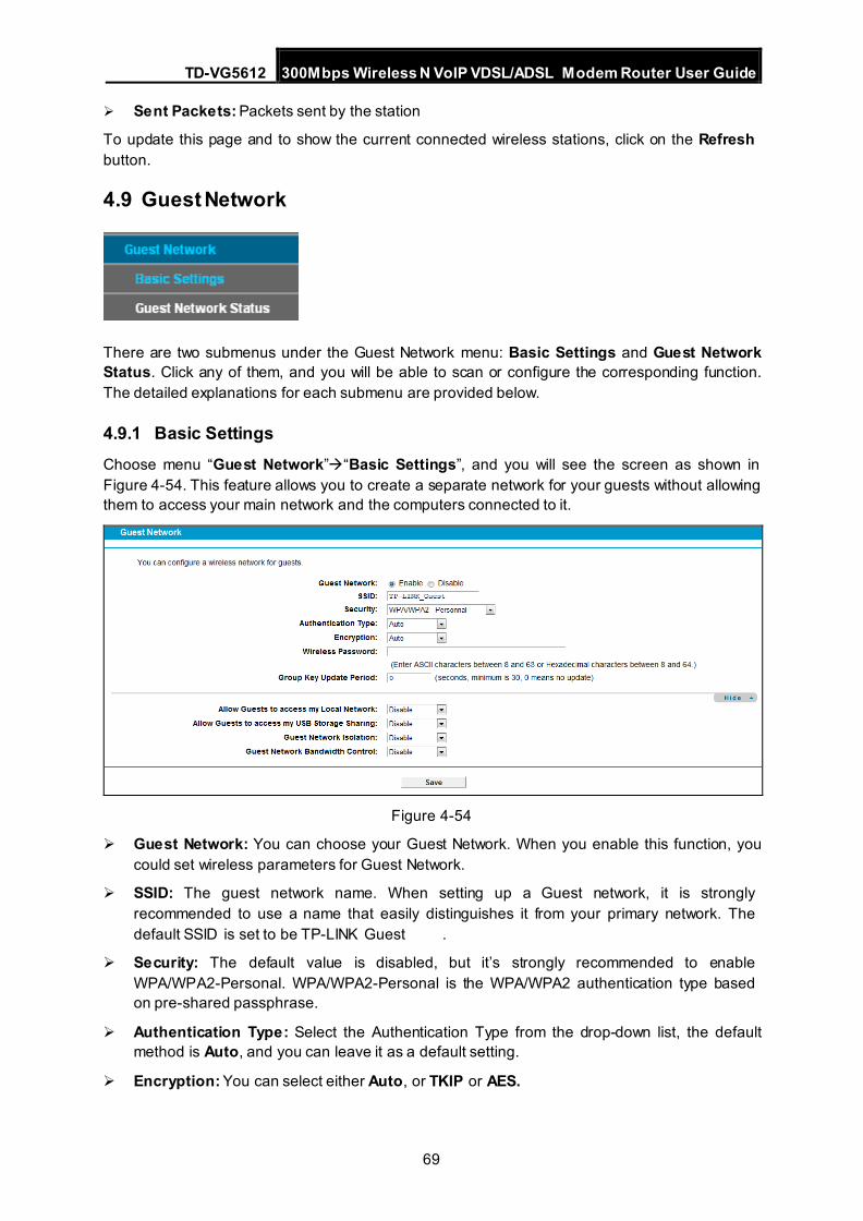
TD-VG5612 300Mbps Wireless N VoIP VDSL/ADSL Modem Router User Guide
69
Sent Packets: Packets sent by the station
To update this page and to show the current connected wireless stations, click on the Refresh button.
4.9 Guest Network
There are two submenus under the Guest Network menu: Basic Settings and Guest Network Status. Click any of them, and you will be able to scan or configure the corresponding function. The detailed explanations for each submenu are provided below.
4.9.1 Basic Settings Choose menu “Guest Network”“Basic Settings”, and you will see the screen as shown in Figure 4-54. This feature allows you to create a separate network for your guests without allowing them to access your main network and the computers connected to it.
Figure 4-54
Guest Network: You can choose your Guest Network. When you enable this function, you could set wireless parameters for Guest Network.
SSID: The guest network name. When setting up a Guest network, it is strongly recommended to use a name that easily distinguishes it from your primary network. The default SSID is set to be TP-LINK Guest .
Security: The default value is disabled, but it’s strongly recommended to enable WPA/WPA2-Personal. WPA/WPA2-Personal is the WPA/WPA2 authentication type based on pre-shared passphrase.
Authentication Type: Select the Authentication Type from the drop-down list, the default method is Auto, and you can leave it as a default setting.
Encryption: You can select either Auto, or TKIP or AES.
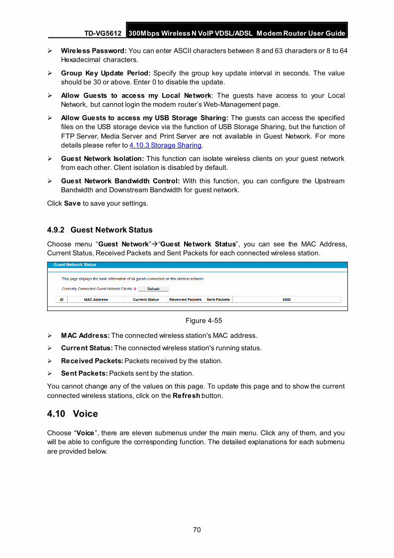
TD-VG5612 300Mbps Wireless N VoIP VDSL/ADSL Modem Router User Guide
70
Wireless Password: You can enter ASCII characters between 8 and 63 characters or 8 to 64 Hexadecimal characters.
Group Key Update Period: Specify the group key update interval in seconds. The value should be 30 or above. Enter 0 to disable the update.
Allow Guests to access my Local Network: The guests have access to your Local Network, but cannot login the modem router’s Web-Management page.
Allow Guests to access my USB Storage Sharing: The guests can access the specified files on the USB storage device via the function of USB Storage Sharing, but the function of FTP Server, Media Server and Print Server are not available in Guest Network. For more details please refer to 4.10.3 Storage Sharing.
Guest Network Isolation: This function can isolate wireless clients on your guest network from each other. Client isolation is disabled by default.
Guest Network Bandwidth Control: With this function, you can configure the Upstream Bandwidth and Downstream Bandwidth for guest network.
Click Save to save your settings.
4.9.2 Guest Network Status Choose menu “Guest Network”“Guest Network Status”, you can see the MAC Address, Current Status, Received Packets and Sent Packets for each connected wireless station.
Figure 4-55
MAC Address: The connected wireless station's MAC address.
Current Status: The connected wireless station's running status.
Received Packets: Packets received by the station.
Sent Packets: Packets sent by the station.
You cannot change any of the values on this page. To update this page and to show the current connected wireless stations, click on the Refresh button.
4.10 Voice
Choose “Voice”, there are eleven submenus under the main menu. Click any of them, and you will be able to configure the corresponding function. The detailed explanations for each submenu are provided below.
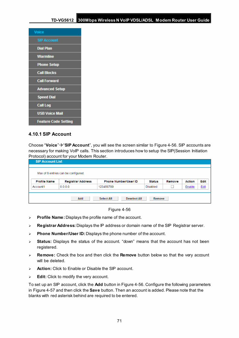
TD-VG5612 300Mbps Wireless N VoIP VDSL/ADSL Modem Router User Guide
71
4.10.1 SIP Account
Choose “Voice”“SIP Account”, you will see the screen similar to Figure 4-56. SIP accounts are necessary for making VoIP calls. This section introduces how to setup the SIP(Session Initiation Protocol) account for your Modem Router.
Figure 4-56
Profile Name: Displays the profile name of the account.
Registrar Address: Displays the IP address or domain name of the SIP Registrar server.
Phone Number/User ID: Displays the phone number of the account.
Status: Displays the status of the account. “down” means that the account has not been registered.
Remove: Check the box and then click the Remove button below so that the very account will be deleted.
Action: Click to Enable or Disable the SIP account.
Edit: Click to modify the very account.
To set up an SIP account, click the Add button in Figure 4-56. Configure the following parameters in Figure 4-57 and then click the Save button. Then an account is added. Please note that the blanks with red asterisk behind are required to be entered.
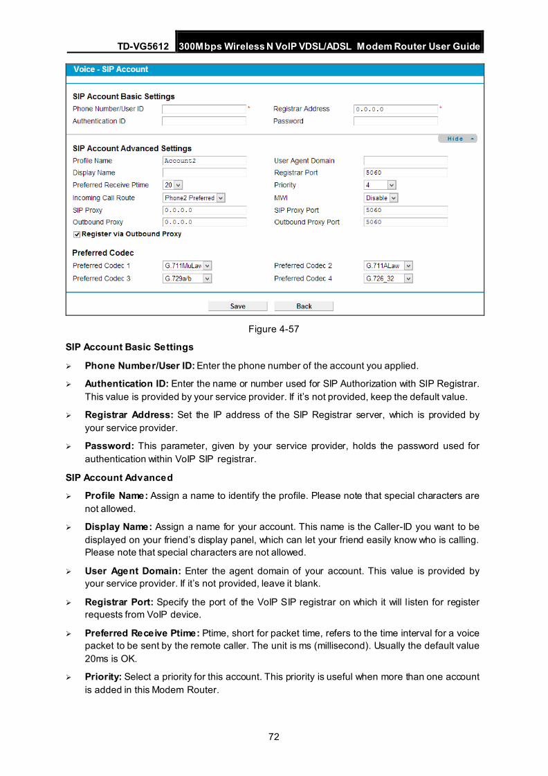
TD-VG5612 300Mbps Wireless N VoIP VDSL/ADSL Modem Router User Guide
72
Figure 4-57
SIP Account Basic Settings
Phone Number/User ID: Enter the phone number of the account you applied.
Authentication ID: Enter the name or number used for SIP Authorization with SIP Registrar. This value is provided by your service provider. If it’s not provided, keep the default value.
Registrar Address: Set the IP address of the SIP Registrar server, which is provided by your service provider.
Password: This parameter, given by your service provider, holds the password used for authentication within VoIP SIP registrar.
SIP Account Advanced
Profile Name: Assign a name to identify the profile. Please note that special characters are not allowed.
Display Name: Assign a name for your account. This name is the Caller-ID you want to be displayed on your friend’s display panel, which can let your friend easily know who is calling. Please note that special characters are not allowed.
User Agent Domain: Enter the agent domain of your account. This value is provided by your service provider. If it’s not provided, leave it blank.
Registrar Port: Specify the port of the VoIP SIP registrar on which it will listen for register requests from VoIP device.
Preferred Receive Ptime: Ptime, short for packet time, refers to the time interval for a voice packet to be sent by the remote caller. The unit is ms (millisecond). Usually the default value 20ms is OK.
Priority: Select a priority for this account. This priority is useful when more than one account is added in this Modem Router.
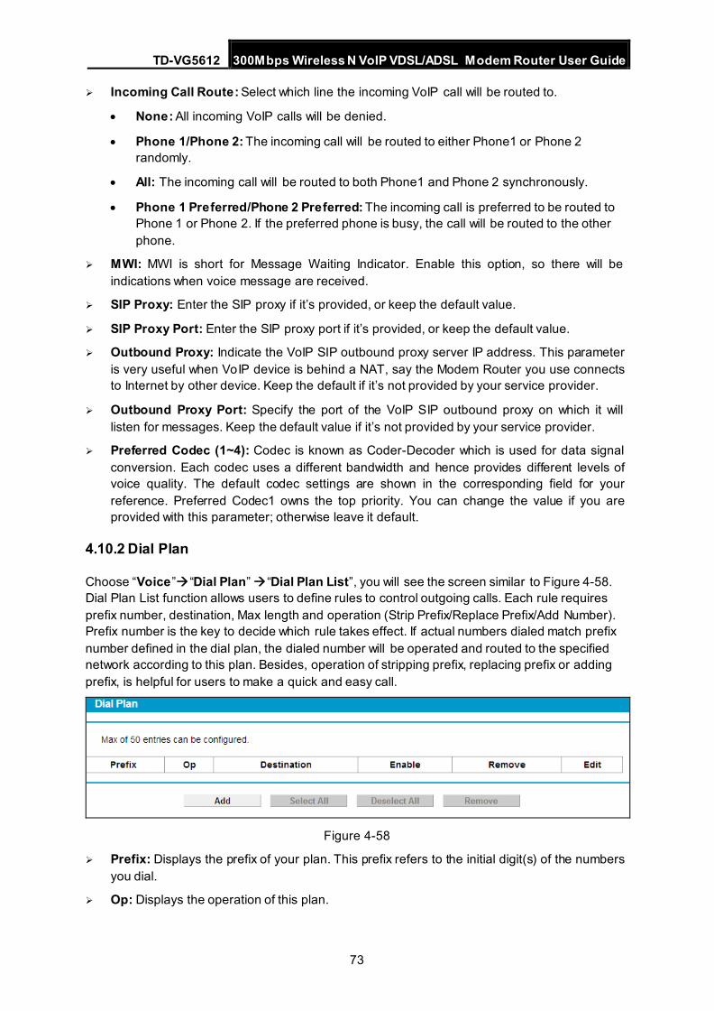
TD-VG5612 300Mbps Wireless N VoIP VDSL/ADSL Modem Router User Guide
73
Incoming Call Route: Select which line the incoming VoIP call will be routed to.
• None: All incoming VoIP calls will be denied.
• Phone 1/Phone 2: The incoming call will be routed to either Phone1 or Phone 2 randomly.
• All: The incoming call will be routed to both Phone1 and Phone 2 synchronously.
• Phone 1 Preferred/Phone 2 Preferred: The incoming call is preferred to be routed to Phone 1 or Phone 2. If the preferred phone is busy, the call will be routed to the other phone.
MWI: MWI is short for Message Waiting Indicator. Enable this option, so there will be indications when voice message are received.
SIP Proxy: Enter the SIP proxy if it’s provided, or keep the default value.
SIP Proxy Port: Enter the SIP proxy port if it’s provided, or keep the default value.
Outbound Proxy: Indicate the VoIP SIP outbound proxy server IP address. This parameter is very useful when VoIP device is behind a NAT, say the Modem Router you use connects to Internet by other device. Keep the default if it’s not provided by your service provider.
Outbound Proxy Port: Specify the port of the VoIP SIP outbound proxy on which it will listen for messages. Keep the default value if it’s not provided by your service provider.
Preferred Codec (1~4): Codec is known as Coder-Decoder which is used for data signal conversion. Each codec uses a different bandwidth and hence provides different levels of voice quality. The default codec settings are shown in the corresponding field for your reference. Preferred Codec1 owns the top priority. You can change the value if you are provided with this parameter; otherwise leave it default.
4.10.2 Dial Plan
Choose “Voice”“Dial Plan” “Dial Plan List”, you will see the screen similar to Figure 4-58. Dial Plan List function allows users to define rules to control outgoing calls. Each rule requires prefix number, destination, Max length and operation (Strip Prefix/Replace Prefix/Add Number). Prefix number is the key to decide which rule takes effect. If actual numbers dialed match prefix number defined in the dial plan, the dialed number will be operated and routed to the specified network according to this plan. Besides, operation of stripping prefix, replacing prefix or adding prefix, is helpful for users to make a quick and easy call.
Figure 4-58
Prefix: Displays the prefix of your plan. This prefix refers to the initial digit(s) of the numbers you dial.
Op: Displays the operation of this plan.
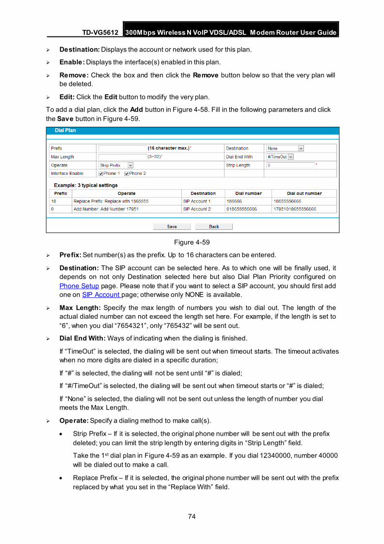
TD-VG5612 300Mbps Wireless N VoIP VDSL/ADSL Modem Router User Guide
74
Destination: Displays the account or network used for this plan.
Enable: Displays the interface(s) enabled in this plan.
Remove: Check the box and then click the Remove button below so that the very plan will be deleted.
Edit: Click the Edit button to modify the very plan.
To add a dial plan, click the Add button in Figure 4-58. Fill in the following parameters and click the Save button in Figure 4-59.
Figure 4-59
Prefix: Set number(s) as the prefix. Up to 16 characters can be entered.
Destination: The SIP account can be selected here. As to which one will be finally used, it depends on not only Destination selected here but also Dial Plan Priority configured on Phone Setup page. Please note that if you want to select a SIP account, you should first add one on SIP Account page; otherwise only NONE is available.
Max Length: Specify the max length of numbers you wish to dial out. The length of the actual dialed number can not exceed the length set here. For example, if the length is set to “6”, when you dial “7654321”, only “765432” will be sent out.
Dial End With: Ways of indicating when the dialing is finished.
If “TimeOut” is selected, the dialing will be sent out when timeout starts. The timeout activates when no more digits are dialed in a specific duration;
If “#” is selected, the dialing will not be sent until “#” is dialed;
If “#/TimeOut” is selected, the dialing will be sent out when timeout starts or “#” is dialed;
If “None” is selected, the dialing will not be sent out unless the length of number you dial meets the Max Length.
Operate: Specify a dialing method to make call(s).
• Strip Prefix – If it is selected, the original phone number will be sent out with the prefix deleted; you can limit the strip length by entering digits in “Strip Length” field.
Take the 1st dial plan in Figure 4-59 as an example. If you dial 12340000, number 40000 will be dialed out to make a call.
• Replace Prefix – If it is selected, the original phone number will be sent out with the prefix replaced by what you set in the “Replace With” field.
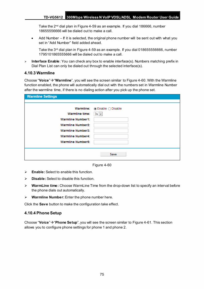
TD-VG5612 300Mbps Wireless N VoIP VDSL/ADSL Modem Router User Guide
75
Take the 2nd dial plan in Figure 4-59 as an example. If you dial 186666, number 18655556666 will be dialed out to make a call.
• Add Number – If it is selected, the original phone number will be sent out with what you set in “Add Number” field added ahead.
Take the 3rd dial plan in Figure 4-59 as an example. If you dial 018655556666, number 1795101865555666 will be dialed out to make a call.
Interface Enable : You can check any box to enable interface(s). Numbers matching prefix in Dial Plan List can only be dialed out through the selected interface(s).
4.10.3 Warmline Choose “Voice”“Warmline”, you will see the screen similar to Figure 4-60. With the Warmline function enabled, the phone will automatically dial out with the numbers set in Warmline Number after the warmline time, if there is no dialing action after you pick up the phone set.
Figure 4-60
Enable: Select to enable this function.
Disable: Select to disable this function.
WarmLine time: Choose WarmLine Time from the drop-down list to specify an interval before the phone dials out automatically.
Warmline Number: Enter the phone number here.
Click the Save button to make the configuration take effect.
4.10.4 Phone Setup
Choose “Voice”“Phone Setup”, you will see the screen similar to Figure 4-61. This section allows you to configure phone settings for phone 1 and phone 2.
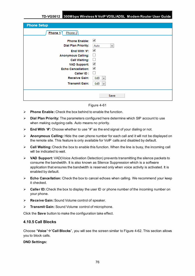
TD-VG5612 300Mbps Wireless N VoIP VDSL/ADSL Modem Router User Guide
76
Figure 4-61
Phone Enable: Check the box behind to enable the function.
Dial Plan Priority: The parameters configured here determine which SIP account to use when making outgoing calls. Auto means no priority.
End With ‘#': Choose whether to use “#” as the end signal of your dialing or not.
Anonymous Calling: Hide the own phone number for each call and it will not be displayed on the remote site. This feature is only available for VoIP calls and disabled by default.
Call Waiting: Check the box to enable this function. When the line is busy, the incoming call will be indicated to wait.
VAD Support: VAD(Voice Activation Detection) prevents transmitting the silence packets to consume the bandwidth. It is also known as Silence Suppression which is a software application that ensures the bandwidth is reserved only when voice activity is activated. It is enabled by default.
Echo Cancellation: Check the box to cancel echoes when calling. We recommend your keep it checked.
Caller ID: Check the box to display the user ID or phone number of the incoming number on your phone.
Receive Gain: Sound Volume control of speaker.
Transmit Gain: Sound Volume control of microphone.
Click the Save button to make the configuration take effect.
4.10.5 Call Blocks
Choose “Voice”“Call Blocks”, you will see the screen similar to Figure 4-62. This section allows you to block calls.
DND Settings:
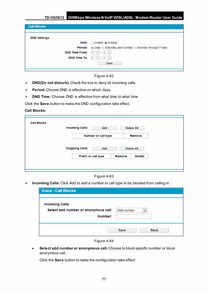
TD-VG5612 300Mbps Wireless N VoIP VDSL/ADSL Modem Router User Guide
77
Figure 4-62
DND(Do not disturb): Check the box to deny all incoming calls.
Period: Choose DND is effective on which days.
DND Time: Choose DND is effective from what time to what time.
Click the Save button to make the DND configuration take effect.
Call Blocks:
Figure 4-63
Incoming Calls: Click Add to add a number or call type to be blocked from calling in.
Figure 4-64
• Select add number or anonymous call: Choose to block specific number or block anonymous call.
Click the Save button to make the configuration take effect.
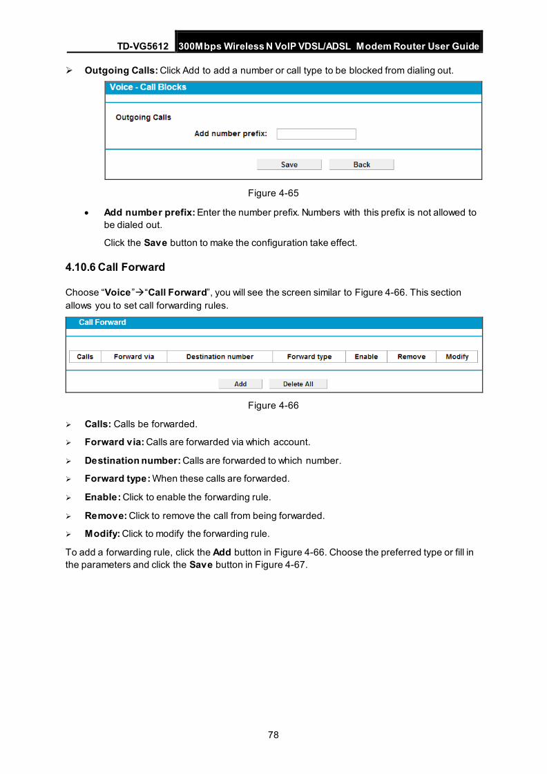
TD-VG5612 300Mbps Wireless N VoIP VDSL/ADSL Modem Router User Guide
78
Outgoing Calls: Click Add to add a number or call type to be blocked from dialing out.
Figure 4-65
• Add number prefix: Enter the number prefix. Numbers with this prefix is not allowed to be dialed out.
Click the Save button to make the configuration take effect.
4.10.6 Call Forward
Choose “Voice”“Call Forward”, you will see the screen similar to Figure 4-66. This section allows you to set call forwarding rules.
Figure 4-66
Calls: Calls be forwarded.
Forward via: Calls are forwarded via which account.
Destination number: Calls are forwarded to which number.
Forward type: When these calls are forwarded.
Enable: Click to enable the forwarding rule.
Remove: Click to remove the call from being forwarded.
Modify: Click to modify the forwarding rule.
To add a forwarding rule, click the Add button in Figure 4-66. Choose the preferred type or fill in the parameters and click the Save button in Figure 4-67.
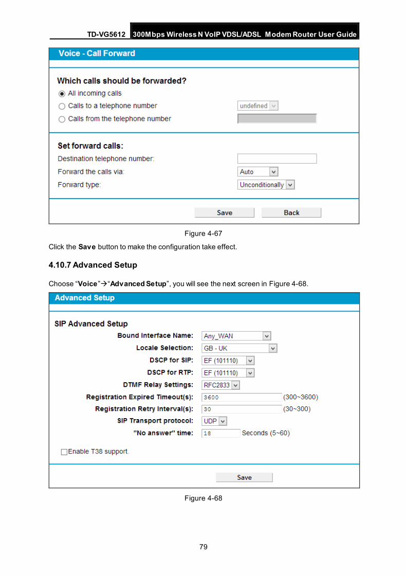
TD-VG5612 300Mbps Wireless N VoIP VDSL/ADSL Modem Router User Guide
79
Figure 4-67
Click the Save button to make the configuration take effect.
4.10.7 Advanced Setup
Choose “Voice”“Advanced Setup”, you will see the next screen in Figure 4-68.
Figure 4-68
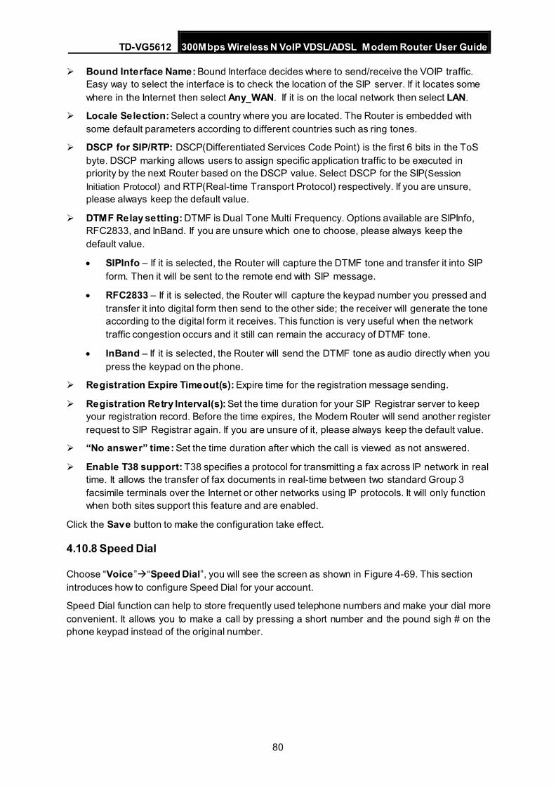
TD-VG5612 300Mbps Wireless N VoIP VDSL/ADSL Modem Router User Guide
80
Bound Interface Name: Bound Interface decides where to send/receive the VOIP traffic. Easy way to select the interface is to check the location of the SIP server. If it locates some where in the Internet then select Any_WAN. If it is on the local network then select LAN.
Locale Selection: Select a country where you are located. The Router is embedded with some default parameters according to different countries such as ring tones.
DSCP for SIP/RTP: DSCP(Differentiated Services Code Point) is the first 6 bits in the ToS byte. DSCP marking allows users to assign specific application traffic to be executed in priority by the next Router based on the DSCP value. Select DSCP for the SIP(Session Initiation Protocol) and RTP(Real-time Transport Protocol) respectively. If you are unsure, please always keep the default value.
DTMF Relay setting: DTMF is Dual Tone Multi Frequency. Options available are SIPInfo, RFC2833, and InBand. If you are unsure which one to choose, please always keep the default value.
• SIPInfo – If it is selected, the Router will capture the DTMF tone and transfer it into SIP form. Then it will be sent to the remote end with SIP message.
• RFC2833 – If it is selected, the Router will capture the keypad number you pressed and transfer it into digital form then send to the other side; the receiver will generate the tone according to the digital form it receives. This function is very useful when the network traffic congestion occurs and it still can remain the accuracy of DTMF tone.
• InBand – If it is selected, the Router will send the DTMF tone as audio directly when you press the keypad on the phone.
Registration Expire Timeout(s): Expire time for the registration message sending.
Registration Retry Interval(s): Set the time duration for your SIP Registrar server to keep your registration record. Before the time expires, the Modem Router will send another register request to SIP Registrar again. If you are unsure of it, please always keep the default value.
“No answer” time: Set the time duration after which the call is viewed as not answered.
Enable T38 support: T38 specifies a protocol for transmitting a fax across IP network in real time. It allows the transfer of fax documents in real-time between two standard Group 3 facsimile terminals over the Internet or other networks using IP protocols. It will only function when both sites support this feature and are enabled.
Click the Save button to make the configuration take effect.
4.10.8 Speed Dial
Choose “Voice”“Speed Dial”, you will see the screen as shown in Figure 4-69. This section introduces how to configure Speed Dial for your account.
Speed Dial function can help to store frequently used telephone numbers and make your dial more convenient. It allows you to make a call by pressing a short number and the pound sigh # on the phone keypad instead of the original number.
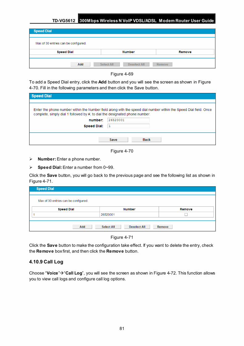
TD-VG5612 300Mbps Wireless N VoIP VDSL/ADSL Modem Router User Guide
81
Figure 4-69
To add a Speed Dial entry, click the Add button and you will see the screen as shown in Figure 4-70. Fill in the following parameters and then click the Save button.
Figure 4-70
Number: Enter a phone number.
Speed Dial: Enter a number from 0~99.
Click the Save button, you will go back to the previous page and see the following list as shown in Figure 4-71.
Figure 4-71
Click the Save button to make the configuration take effect. If you want to delete the entry, check the Remove box first, and then click the Remove button.
4.10.9 Call Log
Choose “Voice”“Call Log”, you will see the screen as shown in Figure 4-72. This function allows you to view call logs and configure call log options.
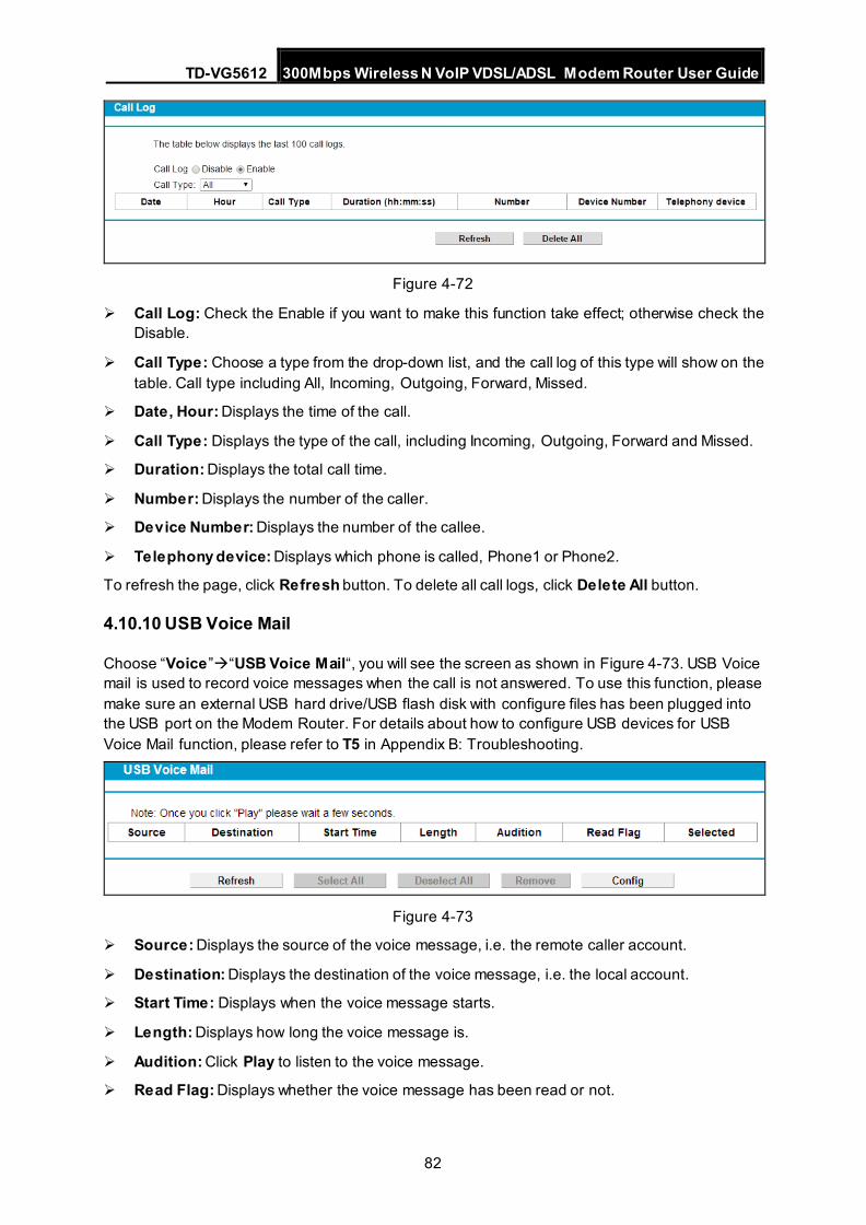
TD-VG5612 300Mbps Wireless N VoIP VDSL/ADSL Modem Router User Guide
82
Figure 4-72
Call Log: Check the Enable if you want to make this function take effect; otherwise check the Disable.
Call Type: Choose a type from the drop-down list, and the call log of this type will show on the table. Call type including All, Incoming, Outgoing, Forward, Missed.
Date, Hour: Displays the time of the call.
Call Type: Displays the type of the call, including Incoming, Outgoing, Forward and Missed.
Duration: Displays the total call time.
Number: Displays the number of the caller.
Device Number: Displays the number of the callee.
Telephony device: Displays which phone is called, Phone1 or Phone2.
To refresh the page, click Refresh button. To delete all call logs, click Delete All button.
4.10.10 USB Voice Mail
Choose “Voice”“USB Voice Mail“, you will see the screen as shown in Figure 4-73. USB Voice mail is used to record voice messages when the call is not answered. To use this function, please make sure an external USB hard drive/USB flash disk with configure files has been plugged into the USB port on the Modem Router. For details about how to configure USB devices for USB Voice Mail function, please refer to T5 in Appendix B: Troubleshooting.
Figure 4-73
Source: Displays the source of the voice message, i.e. the remote caller account.
Destination: Displays the destination of the voice message, i.e. the local account.
Start Time: Displays when the voice message starts.
Length: Displays how long the voice message is.
Audition: Click Play to listen to the voice message.
Read Flag: Displays whether the voice message has been read or not.
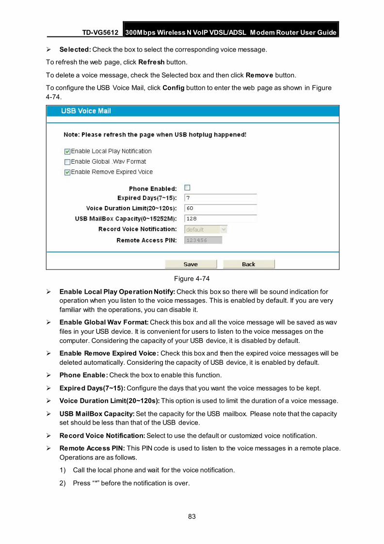
TD-VG5612 300Mbps Wireless N VoIP VDSL/ADSL Modem Router User Guide
83
Selected: Check the box to select the corresponding voice message.
To refresh the web page, click Refresh button.
To delete a voice message, check the Selected box and then click Remove button.
To configure the USB Voice Mail, click Config button to enter the web page as shown in Figure 4-74.
Figure 4-74
Enable Local Play Operation Notify: Check this box so there will be sound indication for operation when you listen to the voice messages. This is enabled by default. If you are very familiar with the operations, you can disable it.
Enable Global Wav Format: Check this box and all the voice message will be saved as wav files in your USB device. It is convenient for users to listen to the voice messages on the computer. Considering the capacity of your USB device, it is disabled by default.
Enable Remove Expired Voice: Check this box and then the expired voice messages will be deleted automatically. Considering the capacity of USB device, it is enabled by default.
Phone Enable: Check the box to enable this function.
Expired Days(7~15): Configure the days that you want the voice messages to be kept.
Voice Duration Limit(20~120s): This option is used to limit the duration of a voice message.
USB MailBox Capacity: Set the capacity for the USB mailbox. Please note that the capacity set should be less than that of the USB device.
Record Voice Notification: Select to use the default or customized voice notification.
Remote Access PIN: This PIN code is used to listen to the voice messages in a remote place. Operations are as follows.
1) Call the local phone and wait for the voice notification.
2) Press “*” before the notification is over.
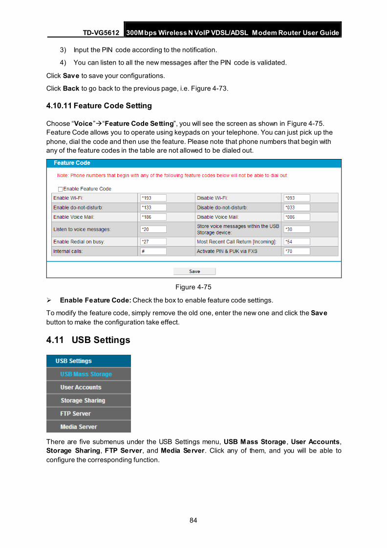
TD-VG5612 300Mbps Wireless N VoIP VDSL/ADSL Modem Router User Guide
84
3) Input the PIN code according to the notification.
4) You can listen to all the new messages after the PIN code is validated.
Click Save to save your configurations.
Click Back to go back to the previous page, i.e. Figure 4-73.
4.10.11 Feature Code Setting
Choose “Voice”“Feature Code Setting”, you will see the screen as shown in Figure 4-75. Feature Code allows you to operate using keypads on your telephone. You can just pick up the phone, dial the code and then use the feature. Please note that phone numbers that begin with any of the feature codes in the table are not allowed to be dialed out.
Figure 4-75
Enable Feature Code: Check the box to enable feature code settings.
To modify the feature code, simply remove the old one, enter the new one and click the Save button to make the configuration take effect.
4.11 USB Settings
There are five submenus under the USB Settings menu, USB Mass Storage , User Accounts, Storage Sharing, FTP Server, and Media Server. Click any of them, and you will be able to configure the corresponding function.
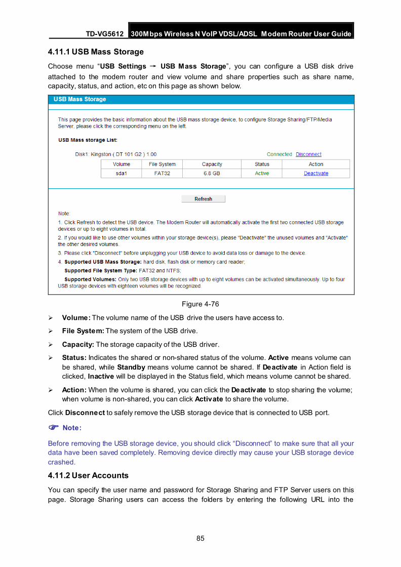
TD-VG5612 300Mbps Wireless N VoIP VDSL/ADSL Modem Router User Guide
85
4.11.1 USB Mass Storage Choose menu “USB Settings → USB Mass Storage”, you can configure a USB disk drive attached to the modem router and view volume and share properties such as share name, capacity, status, and action, etc on this page as shown below.
Figure 4-76
Volume: The volume name of the USB drive the users have access to.
File System: The system of the USB drive.
Capacity: The storage capacity of the USB driver.
Status: Indicates the shared or non-shared status of the volume. Active means volume can be shared, while Standby means volume cannot be shared. If Deactivate in Action field is clicked, Inactive will be displayed in the Status field, which means volume cannot be shared.
Action: When the volume is shared, you can click the Deactivate to stop sharing the volume; when volume is non-shared, you can click Activate to share the volume.
Click Disconnect to safely remove the USB storage device that is connected to USB port.
Note:
Before removing the USB storage device, you should click “Disconnect” to make sure that all your data have been saved completely. Removing device directly may cause your USB storage device crashed.
4.11.2 User Accounts You can specify the user name and password for Storage Sharing and FTP Server users on this page. Storage Sharing users can access the folders by entering the following URL into the
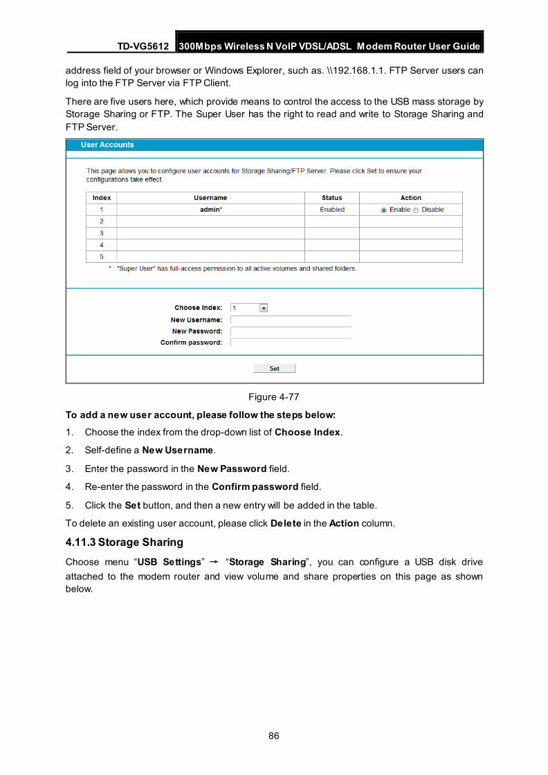
TD-VG5612 300Mbps Wireless N VoIP VDSL/ADSL Modem Router User Guide
86
address field of your browser or Windows Explorer, such as. \\192.168.1.1. FTP Server users can log into the FTP Server via FTP Client.
There are five users here, which provide means to control the access to the USB mass storage by Storage Sharing or FTP. The Super User has the right to read and write to Storage Sharing and FTP Server.
Figure 4-77
To add a new user account, please follow the steps below: 1. Choose the index from the drop-down list of Choose Index.
2. Self-define a New Username.
3. Enter the password in the New Password field.
4. Re-enter the password in the Confirm password field.
5. Click the Set button, and then a new entry will be added in the table.
To delete an existing user account, please click Delete in the Action column.
4.11.3 Storage Sharing Choose menu “USB Settings” → “Storage Sharing”, you can configure a USB disk drive attached to the modem router and view volume and share properties on this page as shown below.
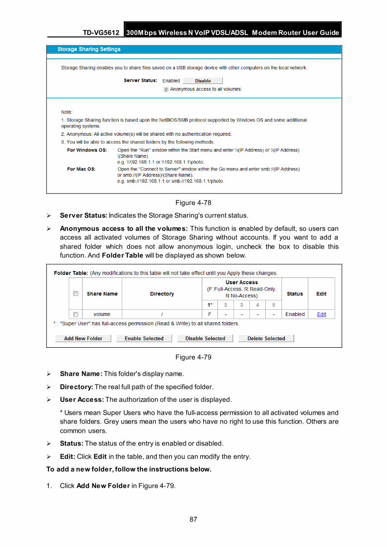
TD-VG5612 300Mbps Wireless N VoIP VDSL/ADSL Modem Router User Guide
87
Figure 4-78
Server Status: Indicates the Storage Sharing's current status.
Anonymous access to all the volumes: This function is enabled by default, so users can access all activated volumes of Storage Sharing without accounts. If you want to add a shared folder which does not allow anonymous login, uncheck the box to disable this function. And Folder Table will be displayed as shown below.
Figure 4-79
Share Name: This folder's display name.
Directory: The real full path of the specified folder.
User Access: The authorization of the user is displayed.
* Users mean Super Users who have the full-access permission to all activated volumes and share folders. Grey users mean the users who have no right to use this function. Others are common users.
Status: The status of the entry is enabled or disabled.
Edit: Click Edit in the table, and then you can modify the entry.
To add a new folder, follow the instructions below.
1. Click Add New Folder in Figure 4-79.
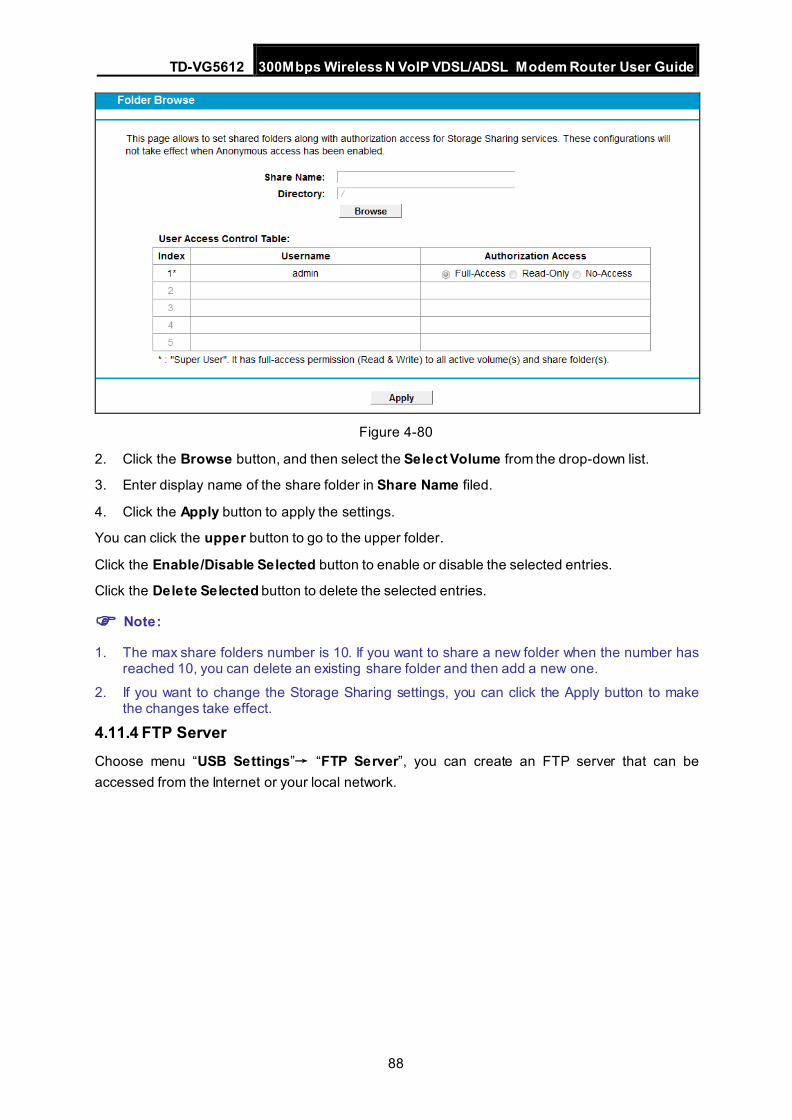
TD-VG5612 300Mbps Wireless N VoIP VDSL/ADSL Modem Router User Guide
88
Figure 4-80
2. Click the Browse button, and then select the Select Volume from the drop-down list.
3. Enter display name of the share folder in Share Name filed.
4. Click the Apply button to apply the settings.
You can click the upper button to go to the upper folder.
Click the Enable/Disable Selected button to enable or disable the selected entries.
Click the Delete Selected button to delete the selected entries.
Note:
1. The max share folders number is 10. If you want to share a new folder when the number has reached 10, you can delete an existing share folder and then add a new one.
2. If you want to change the Storage Sharing settings, you can click the Apply button to make the changes take effect.
4.11.4 FTP Server Choose menu “USB Settings”→ “FTP Server”, you can create an FTP server that can be accessed from the Internet or your local network.
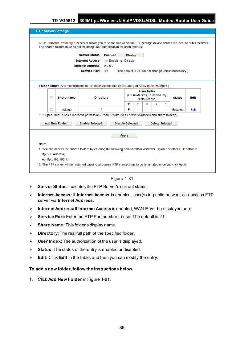
TD-VG5612 300Mbps Wireless N VoIP VDSL/ADSL Modem Router User Guide
89
Figure 4-81
Server Status: Indicates the FTP Server's current status.
Internet Access: If Internet Access is enabled, user(s) in public network can access FTP server via Internet Address.
Internet Address: If Internet Access is enabled, WAN IP will be displayed here.
Service Port: Enter the FTP Port number to use. The default is 21.
Share Name: This folder's display name.
Directory: The real full path of the specified folder.
User Index: The authorization of the user is displayed.
Status: The status of the entry is enabled or disabled.
Edit: Click Edit in the table, and then you can modify the entry.
To add a new folder, follow the instructions below.
1. Click Add New Folder in Figure 4-81.
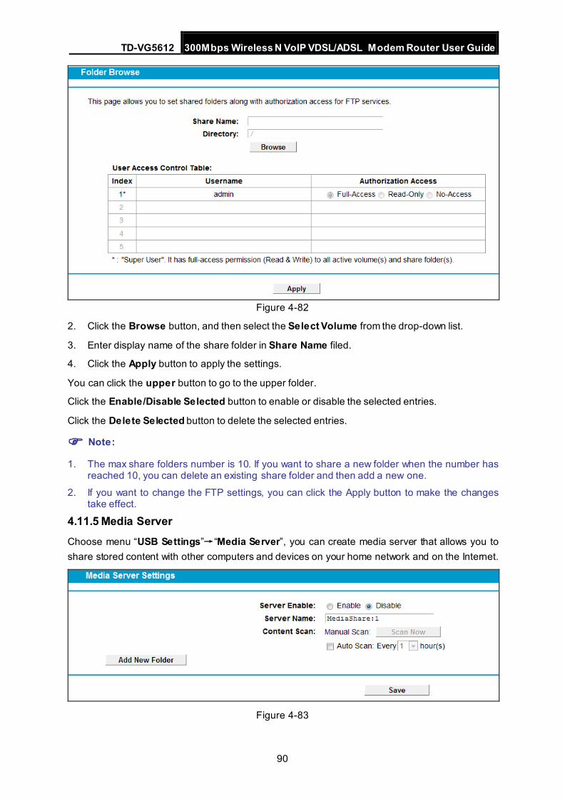
TD-VG5612 300Mbps Wireless N VoIP VDSL/ADSL Modem Router User Guide
90
Figure 4-82
2. Click the Browse button, and then select the Select Volume from the drop-down list.
3. Enter display name of the share folder in Share Name filed.
4. Click the Apply button to apply the settings.
You can click the upper button to go to the upper folder.
Click the Enable/Disable Selected button to enable or disable the selected entries.
Click the Delete Selected button to delete the selected entries.
Note:
1. The max share folders number is 10. If you want to share a new folder when the number has reached 10, you can delete an existing share folder and then add a new one.
2. If you want to change the FTP settings, you can click the Apply button to make the changes take effect.
4.11.5 Media Server Choose menu “USB Settings”→“Media Server”, you can create media server that allows you to share stored content with other computers and devices on your home network and on the Internet.
Figure 4-83
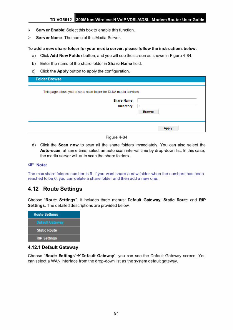
TD-VG5612 300Mbps Wireless N VoIP VDSL/ADSL Modem Router User Guide
91
Server Enable: Select this box to enable this function.
Server Name : The name of this Media Server.
To add a new share folder for your media server, please follow the instructions below: a) Click Add New Folder button, and you will see the screen as shown in Figure 4-84.
b) Enter the name of the share folder in Share Name field.
c) Click the Apply button to apply the configuration.
Figure 4-84
d) Click the Scan now to scan all the share folders immediately. You can also select the Auto-scan, at same time, select an auto scan interval time by drop-down list. In this case, the media server will auto scan the share folders.
Note:
The max share folders number is 6. If you want share a new folder when the numbers has been reached to be 6, you can delete a share folder and then add a new one.
4.12 Route Settings
Choose “Route Settings”, it includes three menus: Default Gateway, Static Route and RIP Settings. The detailed descriptions are provided below.
4.12.1 Default Gateway Choose “Route Settings”“Default Gateway”, you can see the Default Gateway screen. You can select a WAN Interface from the drop-down list as the system default gateway.
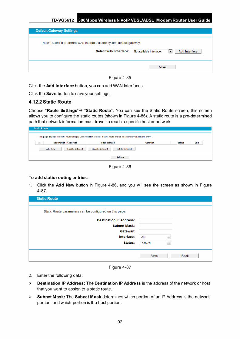
TD-VG5612 300Mbps Wireless N VoIP VDSL/ADSL Modem Router User Guide
92
Figure 4-85
Click the Add Interface button, you can add WAN Interfaces.
Click the Save button to save your settings.
4.12.2 Static Route Choose “Route Settings” “Static Route”. You can see the Static Route screen, this screen allows you to configure the static routes (shown in Figure 4-86). A static route is a pre-determined path that network information must travel to reach a specific host or network.
Figure 4-86
To add static routing entries: 1. Click the Add New button in Figure 4-86, and you will see the screen as shown in Figure
4-87.
Figure 4-87
2. Enter the following data:
Destination IP Address: The Destination IP Address is the address of the network or host that you want to assign to a static route.
Subnet Mask: The Subnet Mask determines which portion of an IP Address is the network portion, and which portion is the host portion.
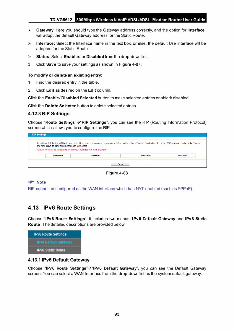
TD-VG5612 300Mbps Wireless N VoIP VDSL/ADSL Modem Router User Guide
93
Gateway: Here you should type the Gateway address correctly, and the option for Interface will adopt the default Gateway address for the Static Route.
Interface: Select the Interface name in the text box, or else, the default Use Interface will be adopted for the Static Route.
Status: Select Enabled or Disabled from the drop-down list.
3. Click Save to save your settings as shown in Figure 4-87.
To modify or delete an existing entry: 1. Find the desired entry in the table.
2. Click Edit as desired on the Edit column.
Click the Enable/ Disabled Selected button to make selected entries enabled/ disabled.
Click the Delete Selected button to delete selected entries.
4.12.3 RIP Settings
Choose “Route Settings”“RIP Settings”, you can see the RIP (Routing Information Protocol) screen which allows you to configure the RIP.
Figure 4-88
Note: RIP cannot be configured on the WAN Interface which has NAT enabled (such as PPPoE).
4.13 IPv6 Route Settings
Choose “IPv6 Route Settings”, it includes two menus: IPv6 Default Gateway and IPv6 Static Route . The detailed descriptions are provided below.
4.13.1 IPv6 Default Gateway Choose “IPv6 Route Settings”“IPv6 Default Gateway”, you can see the Default Gateway screen. You can select a WAN Interface from the drop-down list as the system default gateway.
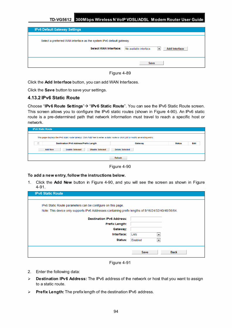
TD-VG5612 300Mbps Wireless N VoIP VDSL/ADSL Modem Router User Guide
94
Figure 4-89
Click the Add Interface button, you can add WAN Interfaces.
Click the Save button to save your settings.
4.13.2 IPv6 Static Route Choose “IPv6 Route Settings” “IPv6 Static Route”. You can see the IPv6 Static Route screen. This screen allows you to configure the IPv6 static routes (shown in Figure 4-90). An IPv6 static route is a pre-determined path that network information must travel to reach a specific host or network.
Figure 4-90
To add a new entry, follow the instructions below. 1. Click the Add New button in Figure 4-90, and you will see the screen as shown in Figure
4-91.
Figure 4-91
2. Enter the following data: Destination IPv6 Address: The IPv6 address of the network or host that you want to assign
to a static route.
Prefix Length: The prefix length of the destination IPv6 address.
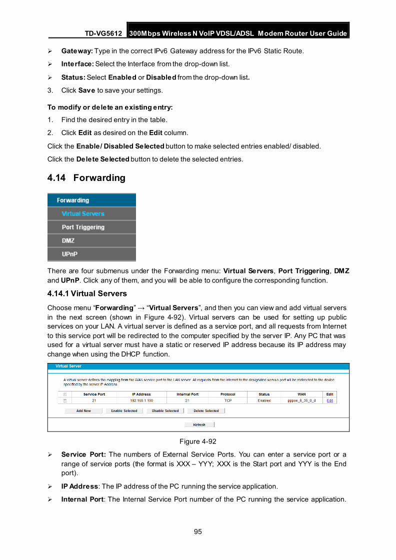
TD-VG5612 300Mbps Wireless N VoIP VDSL/ADSL Modem Router User Guide
95
Gateway: Type in the correct IPv6 Gateway address for the IPv6 Static Route.
Interface: Select the Interface from the drop-down list.
Status: Select Enabled or Disabled from the drop-down list.
3. Click Save to save your settings.
To modify or delete an existing entry: 1. Find the desired entry in the table.
2. Click Edit as desired on the Edit column.
Click the Enable/ Disabled Selected button to make selected entries enabled/ disabled.
Click the Delete Selected button to delete the selected entries.
4.14 Forwarding
There are four submenus under the Forwarding menu: Virtual Servers, Port Triggering, DMZ and UPnP. Click any of them, and you will be able to configure the corresponding function.
4.14.1 Virtual Servers Choose menu “Forwarding” → “Virtual Servers”, and then you can view and add virtual servers in the next screen (shown in Figure 4-92). Virtual servers can be used for setting up public services on your LAN. A virtual server is defined as a service port, and all requests from Internet to this service port will be redirected to the computer specified by the server IP. Any PC that was used for a virtual server must have a static or reserved IP address because its IP address may change when using the DHCP function.
Figure 4-92
Service Port: The numbers of External Service Ports. You can enter a service port or a range of service ports (the format is XXX – YYY; XXX is the Start port and YYY is the End port).
IP Address: The IP address of the PC running the service application.
Internal Port: The Internal Service Port number of the PC running the service application.
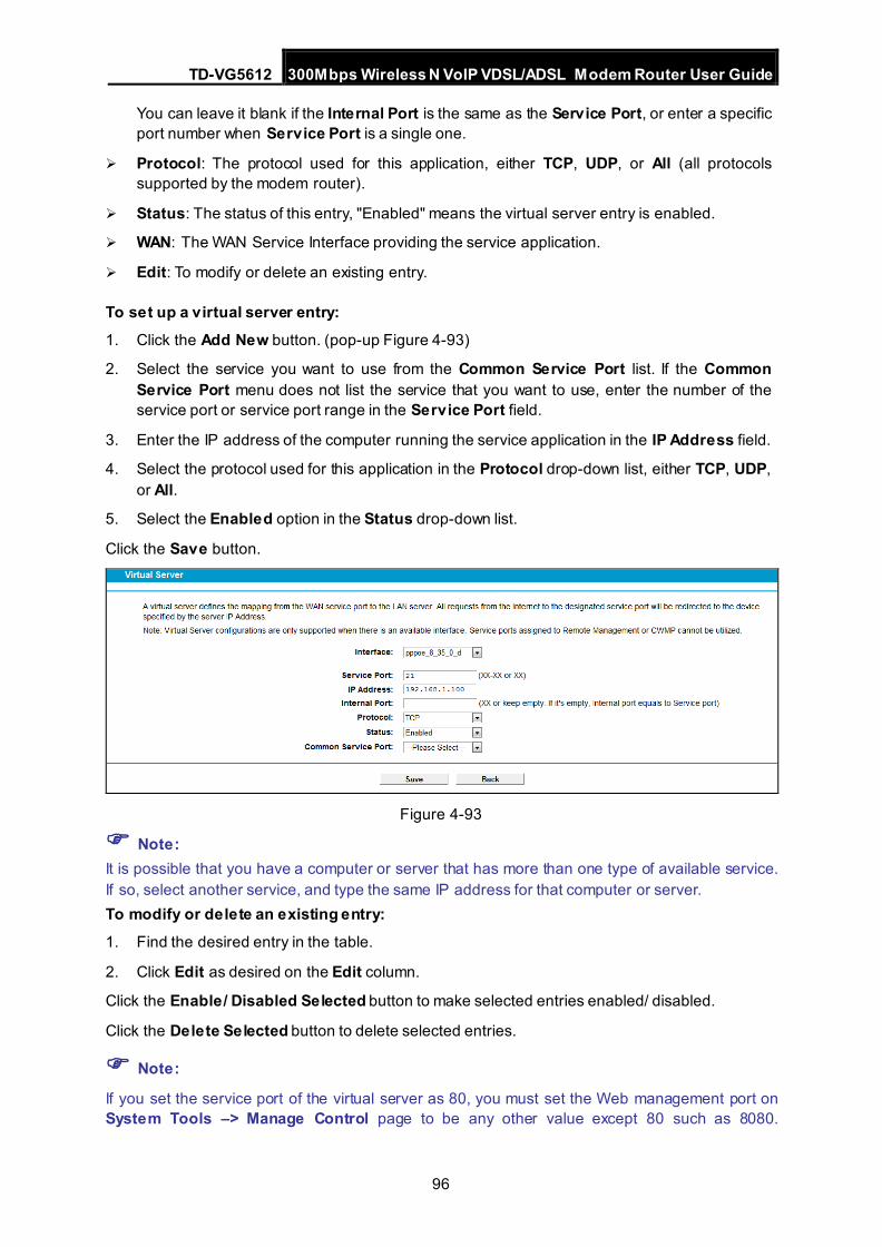
TD-VG5612 300Mbps Wireless N VoIP VDSL/ADSL Modem Router User Guide
96
You can leave it blank if the Internal Port is the same as the Service Port, or enter a specific port number when Service Port is a single one.
Protocol: The protocol used for this application, either TCP, UDP, or All (all protocols supported by the modem router).
Status: The status of this entry, "Enabled" means the virtual server entry is enabled.
WAN: The WAN Service Interface providing the service application.
Edit: To modify or delete an existing entry.
To set up a virtual server entry: 1. Click the Add New button. (pop-up Figure 4-93)
2. Select the service you want to use from the Common Service Port list. If the Common Service Port menu does not list the service that you want to use, enter the number of the service port or service port range in the Service Port field.
3. Enter the IP address of the computer running the service application in the IP Address field.
4. Select the protocol used for this application in the Protocol drop-down list, either TCP, UDP, or All.
5. Select the Enabled option in the Status drop-down list.
Click the Save button.
Figure 4-93
Note: It is possible that you have a computer or server that has more than one type of available service. If so, select another service, and type the same IP address for that computer or server. To modify or delete an existing entry: 1. Find the desired entry in the table.
2. Click Edit as desired on the Edit column.
Click the Enable/ Disabled Selected button to make selected entries enabled/ disabled.
Click the Delete Selected button to delete selected entries.
Note:
If you set the service port of the virtual server as 80, you must set the Web management port on System Tools –> Manage Control page to be any other value except 80 such as 8080.
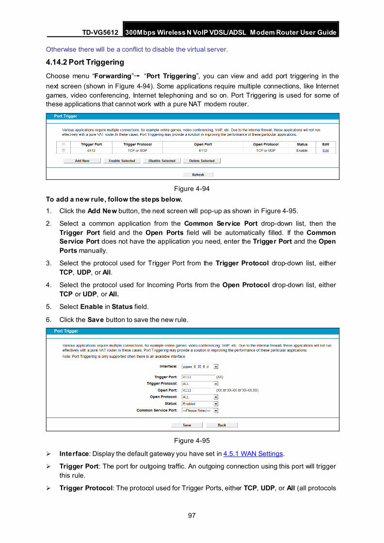
TD-VG5612 300Mbps Wireless N VoIP VDSL/ADSL Modem Router User Guide
97
Otherwise there will be a conflict to disable the virtual server.
4.14.2 Port Triggering Choose menu “Forwarding”→ “Port Triggering”, you can view and add port triggering in the next screen (shown in Figure 4-94). Some applications require multiple connections, like Internet games, video conferencing, Internet telephoning and so on. Port Triggering is used for some of these applications that cannot work with a pure NAT modem router.
Figure 4-94
To add a new rule, follow the steps below. 1. Click the Add New button, the next screen will pop-up as shown in Figure 4-95.
2. Select a common application from the Common Service Port drop-down list, then the Trigger Port field and the Open Ports field will be automatically filled. If the Common Service Port does not have the application you need, enter the Trigger Port and the Open Ports manually.
3. Select the protocol used for Trigger Port from the Trigger Protocol drop-down list, either TCP, UDP, or All.
4. Select the protocol used for Incoming Ports from the Open Protocol drop-down list, either TCP or UDP, or All.
5. Select Enable in Status field.
6. Click the Save button to save the new rule.
Figure 4-95
Interface: Display the default gateway you have set in 4.5.1 WAN Settings.
Trigger Port: The port for outgoing traffic. An outgoing connection using this port will trigger this rule.
Trigger Protocol: The protocol used for Trigger Ports, either TCP, UDP, or All (all protocols
TD-VG5612 300Mbps Wireless N VoIP VDSL/ADSL Modem Router User Guide
98
supported by the modem router).
Open Port: The port or port range used by the remote system when it responds to the outgoing request. A response using one of these ports will be forwarded to the PC which triggered this rule. You can input at most 5 groups of ports (or port sections). Every group of ports must be separated with ",", for example, 2000-2038, 2046, 2050-2051, 2085, 3010-3030.
Open Protocol: The protocol used for Incoming Port, either TCP, UDP, or ALL (all protocols supported by the modem router).
Status: The status of this entry, Enabled means the Port Triggering entry is enabled.
Common Service Port: Some popular applications already listed in the drop-down list of Open Protocol.
To modify or delete an existing entry: 1. Find the desired entry in the table.
2. Click Edit as desired on the Edit column.
Click the Enable/ Disabled Selected button to make selected entries enabled/ disabled.
Click the Delete Selected button to delete selected entries.
Once the modem router is configured, the operation is as follows: 1. A local host makes an outgoing connection to an external host using a destination port
number defined in the Trigger Port field.
2. The modem router records this connection, opens the incoming port or ports associated with this entry in the Port Triggering table, and associates them with the local host.
3. When necessary, the external host will be able to connect to the local host using one of the ports defined in the Incoming Ports field.
Note:
1. When the trigger connection is released, the corresponding opened ports will be closed. 2. Each rule can only be used by one host on the LAN at a time. The trigger connection of other
hosts on the LAN will be refused. 3. Open Ports ranges cannot overlap each other.
4.14.3 DMZ Choose menu “Forwarding→DMZ”, and then you can view and configure DMZ host in the screen (shown in Figure 4-96).The DMZ host feature allows one local host to be exposed to the Internet for a special-purpose service such as Internet gaming or videoconferencing. The modem router forwards packets of all services to the DMZ host. Any PC whose port is being forwarded must have its DHCP client function disabled and should have a new static IP Address assigned to it because its IP Address may be changed when using the DHCP function.
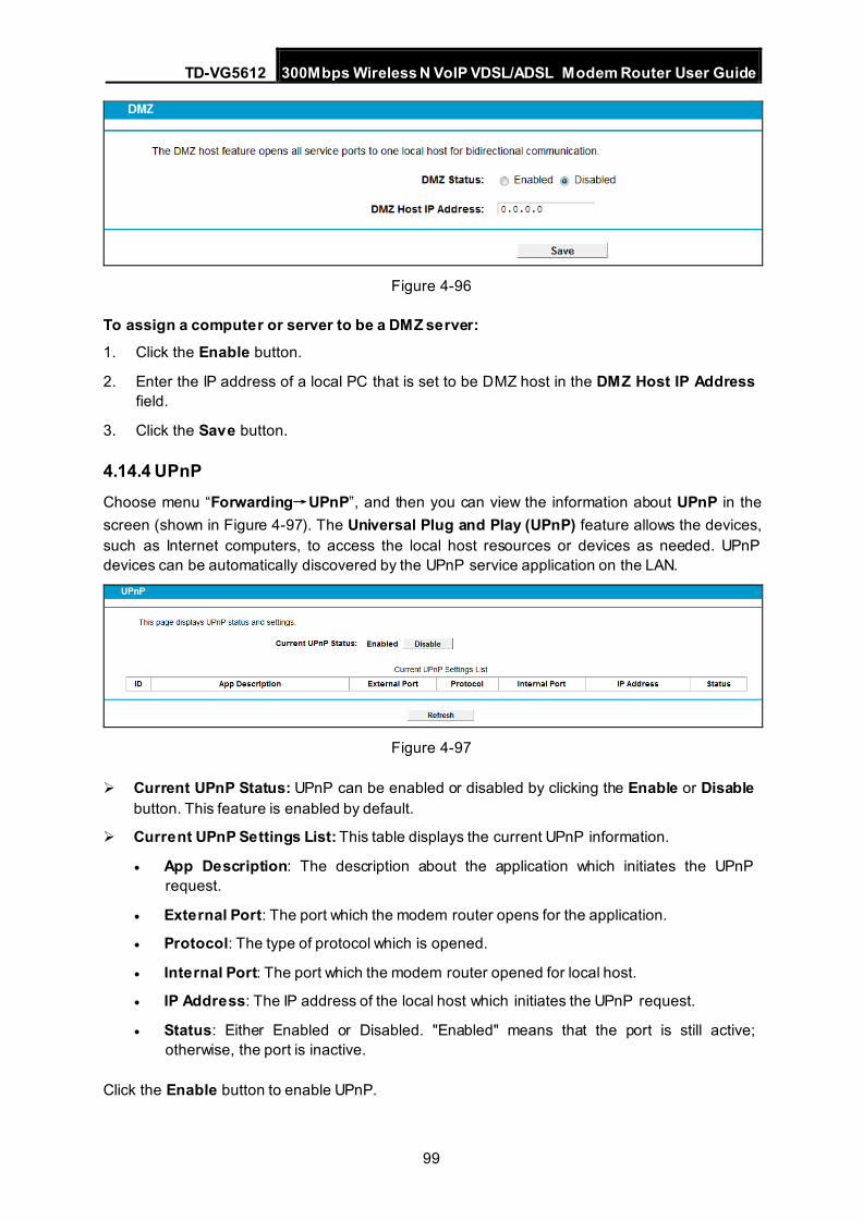
TD-VG5612 300Mbps Wireless N VoIP VDSL/ADSL Modem Router User Guide
99
Figure 4-96
To assign a computer or server to be a DMZ server: 1. Click the Enable button.
2. Enter the IP address of a local PC that is set to be DMZ host in the DMZ Host IP Address field.
3. Click the Save button.
4.14.4 UPnP Choose menu “Forwarding→UPnP”, and then you can view the information about UPnP in the screen (shown in Figure 4-97). The Universal Plug and Play (UPnP) feature allows the devices, such as Internet computers, to access the local host resources or devices as needed. UPnP devices can be automatically discovered by the UPnP service application on the LAN.
Figure 4-97
Current UPnP Status: UPnP can be enabled or disabled by clicking the Enable or Disable button. This feature is enabled by default.
Current UPnP Settings List: This table displays the current UPnP information. • App Description: The description about the application which initiates the UPnP
request.
• External Port: The port which the modem router opens for the application.
• Protocol: The type of protocol which is opened.
• Internal Port: The port which the modem router opened for local host.
• IP Address: The IP address of the local host which initiates the UPnP request.
• Status: Either Enabled or Disabled. "Enabled" means that the port is still active; otherwise, the port is inactive.
Click the Enable button to enable UPnP.
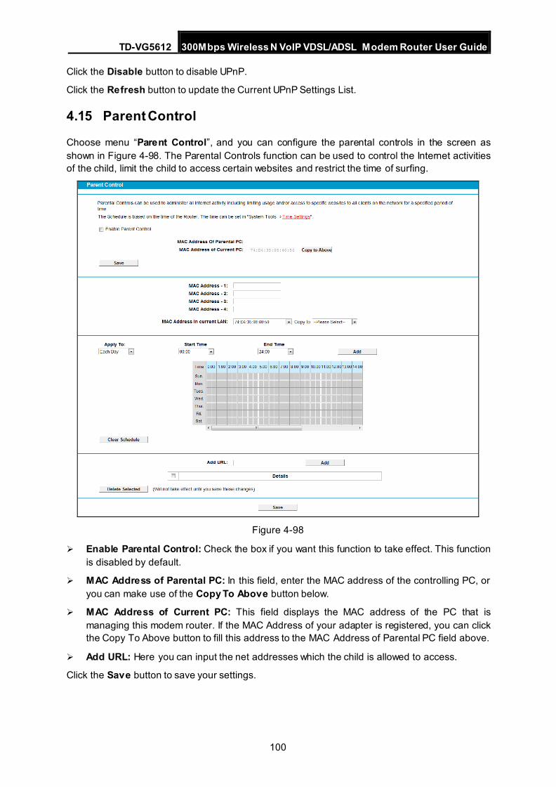
TD-VG5612 300Mbps Wireless N VoIP VDSL/ADSL Modem Router User Guide
100
Click the Disable button to disable UPnP.
Click the Refresh button to update the Current UPnP Settings List.
4.15 Parent Control
Choose menu “Parent Control”, and you can configure the parental controls in the screen as shown in Figure 4-98. The Parental Controls function can be used to control the Internet activities of the child, limit the child to access certain websites and restrict the time of surfing.
Figure 4-98
Enable Parental Control: Check the box if you want this function to take effect. This function is disabled by default.
MAC Address of Parental PC: In this field, enter the MAC address of the controlling PC, or you can make use of the Copy To Above button below.
MAC Address of Current PC: This field displays the MAC address of the PC that is managing this modem router. If the MAC Address of your adapter is registered, you can click the Copy To Above button to fill this address to the MAC Address of Parental PC field above.
Add URL: Here you can input the net addresses which the child is allowed to access.
Click the Save button to save your settings.
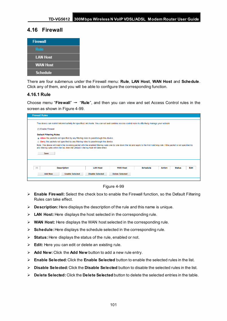
TD-VG5612 300Mbps Wireless N VoIP VDSL/ADSL Modem Router User Guide
101
4.16 Firewall
There are four submenus under the Firewall menu: Rule, LAN Host, WAN Host and Schedule . Click any of them, and you will be able to configure the corresponding function.
4.16.1 Rule Choose menu “Firewall” → “Rule”, and then you can view and set Access Control rules in the screen as shown in Figure 4-99.
Figure 4-99
Enable Firewall: Select the check box to enable the Firewall function, so the Default Filtering Rules can take effect.
Description: Here displays the description of the rule and this name is unique.
LAN Host: Here displays the host selected in the corresponding rule.
WAN Host: Here displays the WAN host selected in the corresponding rule.
Schedule: Here displays the schedule selected in the corresponding rule.
Status: Here displays the status of the rule, enabled or not.
Edit: Here you can edit or delete an existing rule.
Add New: Click the Add New button to add a new rule entry.
Enable Selected: Click the Enable Selected button to enable the selected rules in the list.
Disable Selected: Click the Disable Selected button to disable the selected rules in the list.
Delete Selected: Click the Delete Selected button to delete the selected entries in the table.
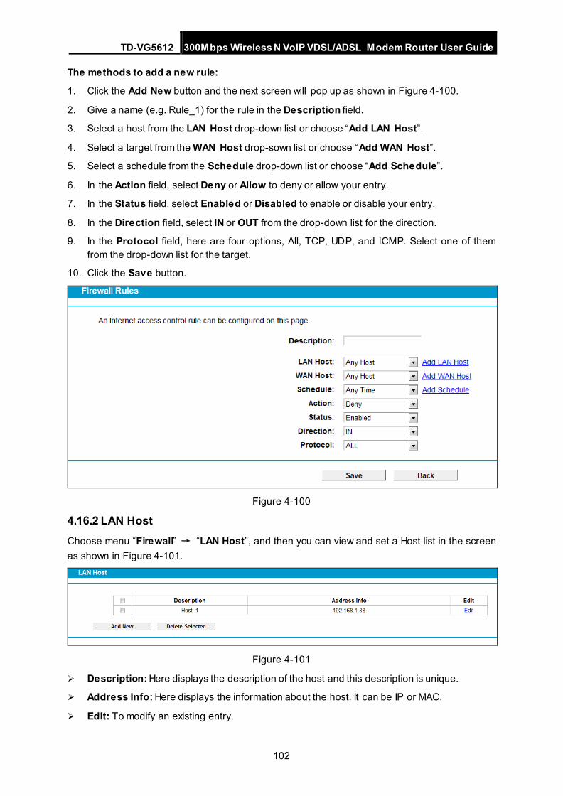
TD-VG5612 300Mbps Wireless N VoIP VDSL/ADSL Modem Router User Guide
102
The methods to add a new rule:
1. Click the Add New button and the next screen will pop up as shown in Figure 4-100.
2. Give a name (e.g. Rule_1) for the rule in the Description field.
3. Select a host from the LAN Host drop-down list or choose “Add LAN Host”.
4. Select a target from the WAN Host drop-sown list or choose “Add WAN Host”.
5. Select a schedule from the Schedule drop-down list or choose “Add Schedule”.
6. In the Action field, select Deny or Allow to deny or allow your entry.
7. In the Status field, select Enabled or Disabled to enable or disable your entry.
8. In the Direction field, select IN or OUT from the drop-down list for the direction.
9. In the Protocol field, here are four options, All, TCP, UDP, and ICMP. Select one of them from the drop-down list for the target.
10. Click the Save button.
Figure 4-100
4.16.2 LAN Host Choose menu “Firewall” → “LAN Host”, and then you can view and set a Host list in the screen as shown in Figure 4-101.
Figure 4-101
Description: Here displays the description of the host and this description is unique.
Address Info: Here displays the information about the host. It can be IP or MAC.
Edit: To modify an existing entry.
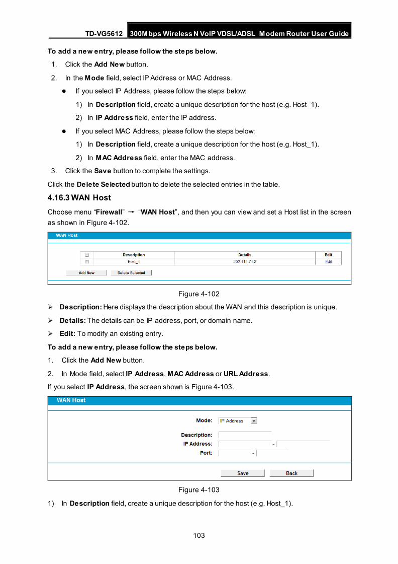
TD-VG5612 300Mbps Wireless N VoIP VDSL/ADSL Modem Router User Guide
103
To add a new entry, please follow the steps below.
1. Click the Add New button.
2. In the Mode field, select IP Address or MAC Address.
If you select IP Address, please follow the steps below:
1) In Description field, create a unique description for the host (e.g. Host_1).
2) In IP Address field, enter the IP address.
If you select MAC Address, please follow the steps below:
1) In Description field, create a unique description for the host (e.g. Host_1).
2) In MAC Address field, enter the MAC address.
3. Click the Save button to complete the settings.
Click the Delete Selected button to delete the selected entries in the table.
4.16.3 WAN Host Choose menu “Firewall” → “WAN Host”, and then you can view and set a Host list in the screen as shown in Figure 4-102.
Figure 4-102
Description: Here displays the description about the WAN and this description is unique.
Details: The details can be IP address, port, or domain name.
Edit: To modify an existing entry.
To add a new entry, please follow the steps below.
1. Click the Add New button.
2. In Mode field, select IP Address, MAC Address or URL Address.
If you select IP Address, the screen shown is Figure 4-103.
Figure 4-103
1) In Description field, create a unique description for the host (e.g. Host_1).
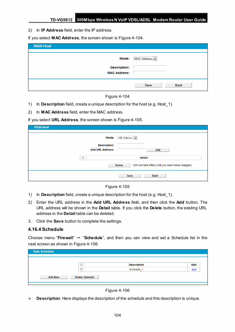
TD-VG5612 300Mbps Wireless N VoIP VDSL/ADSL Modem Router User Guide
104
2) In IP Address field, enter the IP address.
If you select MAC Address, the screen shown is Figure 4-104.
Figure 4-104
1) In Description field, create a unique description for the host (e.g. Host_1).
2) In MAC Address field, enter the MAC address.
If you select URL Address, the screen shown is Figure 4-105.
Figure 4-105
1) In Description field, create a unique description for the host (e.g. Host_1).
2) Enter the URL address in the Add URL Address field, and then click the Add button. The URL address will be shown in the Detail table. If you click the Delete button, the existing URL address in the Detail table can be deleted.
3. Click the Save button to complete the settings.
4.16.4 Schedule Choose menu “Firewall” → “Schedule”, and then you can view and set a Schedule list in the next screen as shown in Figure 4-106.
Figure 4-106
Description: Here displays the description of the schedule and this description is unique.
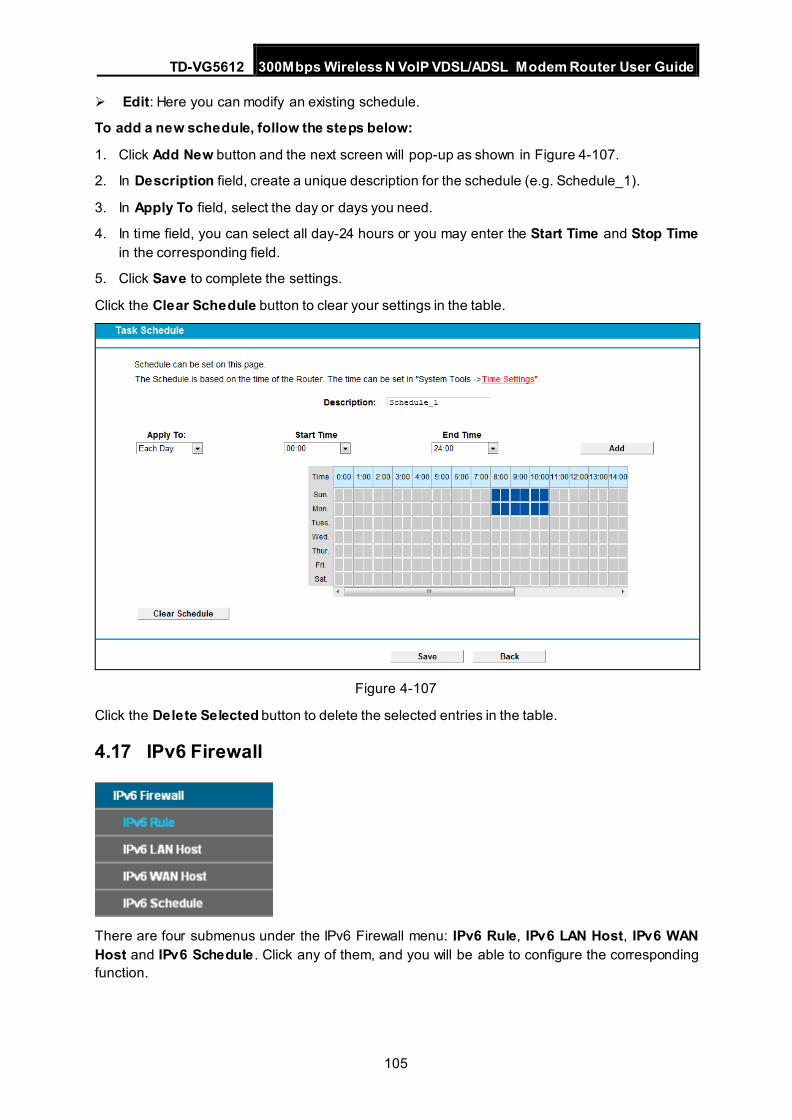
TD-VG5612 300Mbps Wireless N VoIP VDSL/ADSL Modem Router User Guide
105
Edit: Here you can modify an existing schedule.
To add a new schedule, follow the steps below:
1. Click Add New button and the next screen will pop-up as shown in Figure 4-107.
2. In Description field, create a unique description for the schedule (e.g. Schedule_1).
3. In Apply To field, select the day or days you need.
4. In time field, you can select all day-24 hours or you may enter the Start Time and Stop Time in the corresponding field.
5. Click Save to complete the settings.
Click the Clear Schedule button to clear your settings in the table.
Figure 4-107
Click the Delete Selected button to delete the selected entries in the table.
4.17 IPv6 Firewall
There are four submenus under the IPv6 Firewall menu: IPv6 Rule, IPv6 LAN Host, IPv6 WAN Host and IPv6 Schedule . Click any of them, and you will be able to configure the corresponding function.
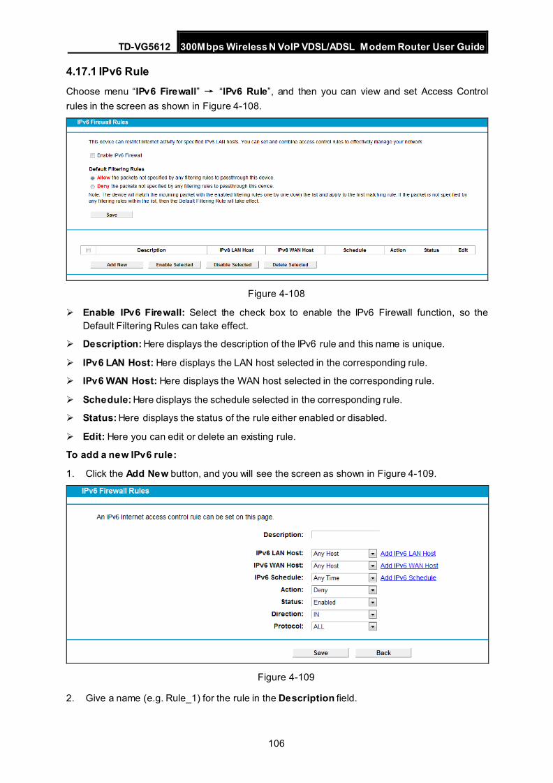
TD-VG5612 300Mbps Wireless N VoIP VDSL/ADSL Modem Router User Guide
106
4.17.1 IPv6 Rule Choose menu “IPv6 Firewall” → “IPv6 Rule”, and then you can view and set Access Control rules in the screen as shown in Figure 4-108.
Figure 4-108
Enable IPv6 Firewall: Select the check box to enable the IPv6 Firewall function, so the Default Filtering Rules can take effect.
Description: Here displays the description of the IPv6 rule and this name is unique.
IPv6 LAN Host: Here displays the LAN host selected in the corresponding rule.
IPv6 WAN Host: Here displays the WAN host selected in the corresponding rule.
Schedule: Here displays the schedule selected in the corresponding rule.
Status: Here displays the status of the rule either enabled or disabled.
Edit: Here you can edit or delete an existing rule.
To add a new IPv6 rule:
1. Click the Add New button, and you will see the screen as shown in Figure 4-109.
Figure 4-109
2. Give a name (e.g. Rule_1) for the rule in the Description field.
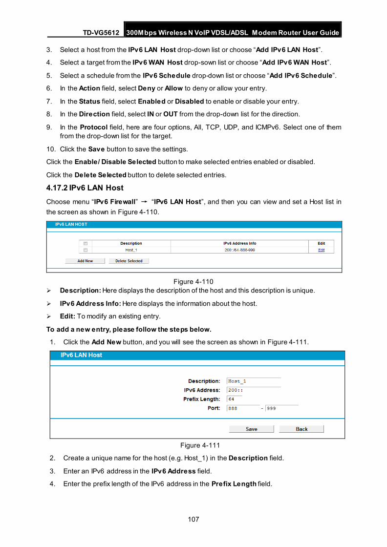
TD-VG5612 300Mbps Wireless N VoIP VDSL/ADSL Modem Router User Guide
107
3. Select a host from the IPv6 LAN Host drop-down list or choose “Add IPv6 LAN Host”.
4. Select a target from the IPv6 WAN Host drop-sown list or choose “Add IPv6 WAN Host”.
5. Select a schedule from the IPv6 Schedule drop-down list or choose “Add IPv6 Schedule”.
6. In the Action field, select Deny or Allow to deny or allow your entry.
7. In the Status field, select Enabled or Disabled to enable or disable your entry.
8. In the Direction field, select IN or OUT from the drop-down list for the direction.
9. In the Protocol field, here are four options, All, TCP, UDP, and ICMPv6. Select one of them from the drop-down list for the target.
10. Click the Save button to save the settings.
Click the Enable/ Disable Selected button to make selected entries enabled or disabled.
Click the Delete Selected button to delete selected entries.
4.17.2 IPv6 LAN Host Choose menu “IPv6 Firewall” → “IPv6 LAN Host”, and then you can view and set a Host list in the screen as shown in Figure 4-110.
Figure 4-110
Description: Here displays the description of the host and this description is unique.
IPv6 Address Info: Here displays the information about the host.
Edit: To modify an existing entry.
To add a new entry, please follow the steps below.
1. Click the Add New button, and you will see the screen as shown in Figure 4-111.
Figure 4-111
2. Create a unique name for the host (e.g. Host_1) in the Description field.
3. Enter an IPv6 address in the IPv6 Address field.
4. Enter the prefix length of the IPv6 address in the Prefix Length field.
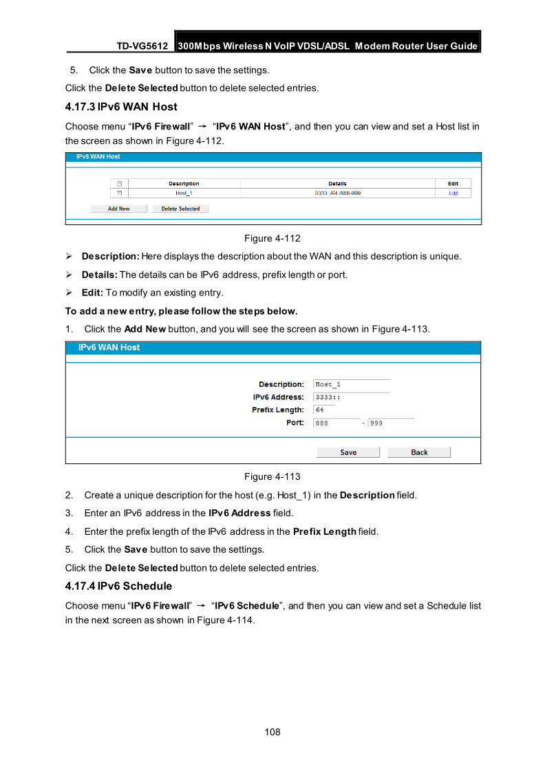
TD-VG5612 300Mbps Wireless N VoIP VDSL/ADSL Modem Router User Guide
108
5. Click the Save button to save the settings.
Click the Delete Selected button to delete selected entries.
4.17.3 IPv6 WAN Host Choose menu “IPv6 Firewall” → “IPv6 WAN Host”, and then you can view and set a Host list in the screen as shown in Figure 4-112.
Figure 4-112
Description: Here displays the description about the WAN and this description is unique.
Details: The details can be IPv6 address, prefix length or port.
Edit: To modify an existing entry.
To add a new entry, please follow the steps below.
1. Click the Add New button, and you will see the screen as shown in Figure 4-113.
Figure 4-113
2. Create a unique description for the host (e.g. Host_1) in the Description field.
3. Enter an IPv6 address in the IPv6 Address field.
4. Enter the prefix length of the IPv6 address in the Prefix Length field.
5. Click the Save button to save the settings.
Click the Delete Selected button to delete selected entries.
4.17.4 IPv6 Schedule Choose menu “IPv6 Firewall” → “IPv6 Schedule”, and then you can view and set a Schedule list in the next screen as shown in Figure 4-114.
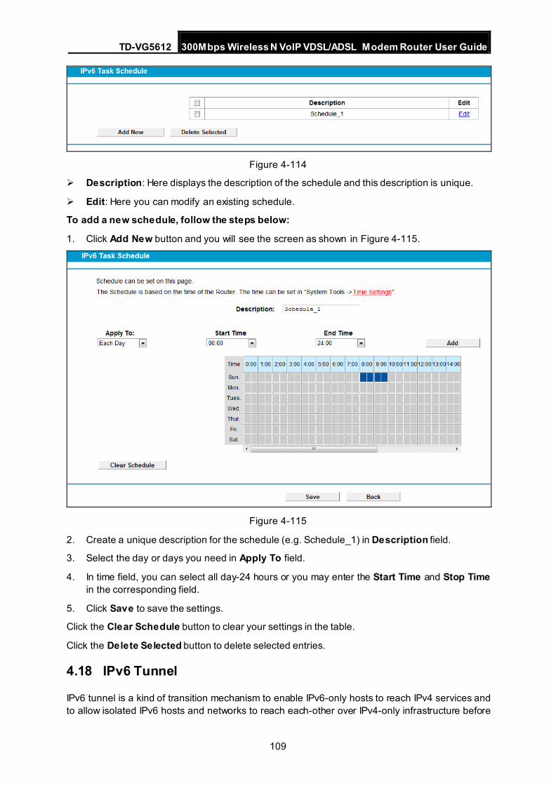
TD-VG5612 300Mbps Wireless N VoIP VDSL/ADSL Modem Router User Guide
109
Figure 4-114
Description: Here displays the description of the schedule and this description is unique.
Edit: Here you can modify an existing schedule.
To add a new schedule, follow the steps below:
1. Click Add New button and you will see the screen as shown in Figure 4-115.
Figure 4-115
2. Create a unique description for the schedule (e.g. Schedule_1) in Description field.
3. Select the day or days you need in Apply To field.
4. In time field, you can select all day-24 hours or you may enter the Start Time and Stop Time in the corresponding field.
5. Click Save to save the settings.
Click the Clear Schedule button to clear your settings in the table.
Click the Delete Selected button to delete selected entries.
4.18 IPv6 Tunnel
IPv6 tunnel is a kind of transition mechanism to enable IPv6-only hosts to reach IPv4 services and to allow isolated IPv6 hosts and networks to reach each-other over IPv4-only infrastructure before
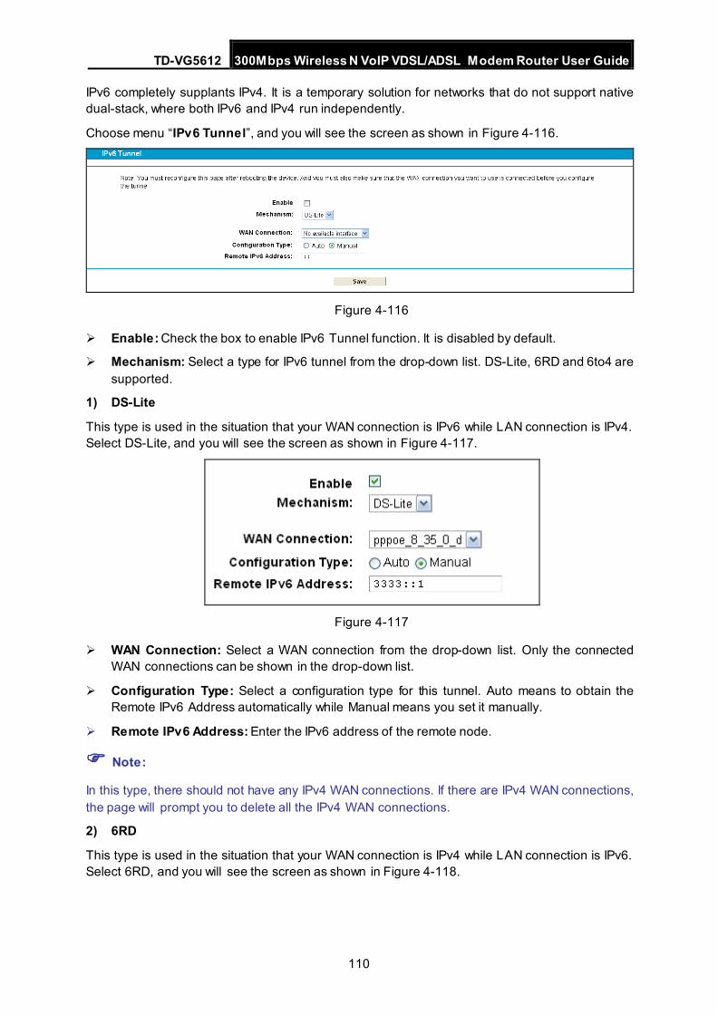
TD-VG5612 300Mbps Wireless N VoIP VDSL/ADSL Modem Router User Guide
110
IPv6 completely supplants IPv4. It is a temporary solution for networks that do not support native dual-stack, where both IPv6 and IPv4 run independently.
Choose menu “IPv6 Tunnel”, and you will see the screen as shown in Figure 4-116.
Figure 4-116
Enable: Check the box to enable IPv6 Tunnel function. It is disabled by default.
Mechanism: Select a type for IPv6 tunnel from the drop-down list. DS-Lite, 6RD and 6to4 are supported.
1) DS-Lite
This type is used in the situation that your WAN connection is IPv6 while LAN connection is IPv4. Select DS-Lite, and you will see the screen as shown in Figure 4-117.
Figure 4-117
WAN Connection: Select a WAN connection from the drop-down list. Only the connected WAN connections can be shown in the drop-down list.
Configuration Type: Select a configuration type for this tunnel. Auto means to obtain the Remote IPv6 Address automatically while Manual means you set it manually.
Remote IPv6 Address: Enter the IPv6 address of the remote node.
Note:
In this type, there should not have any IPv4 WAN connections. If there are IPv4 WAN connections, the page will prompt you to delete all the IPv4 WAN connections.
2) 6RD
This type is used in the situation that your WAN connection is IPv4 while LAN connection is IPv6. Select 6RD, and you will see the screen as shown in Figure 4-118.
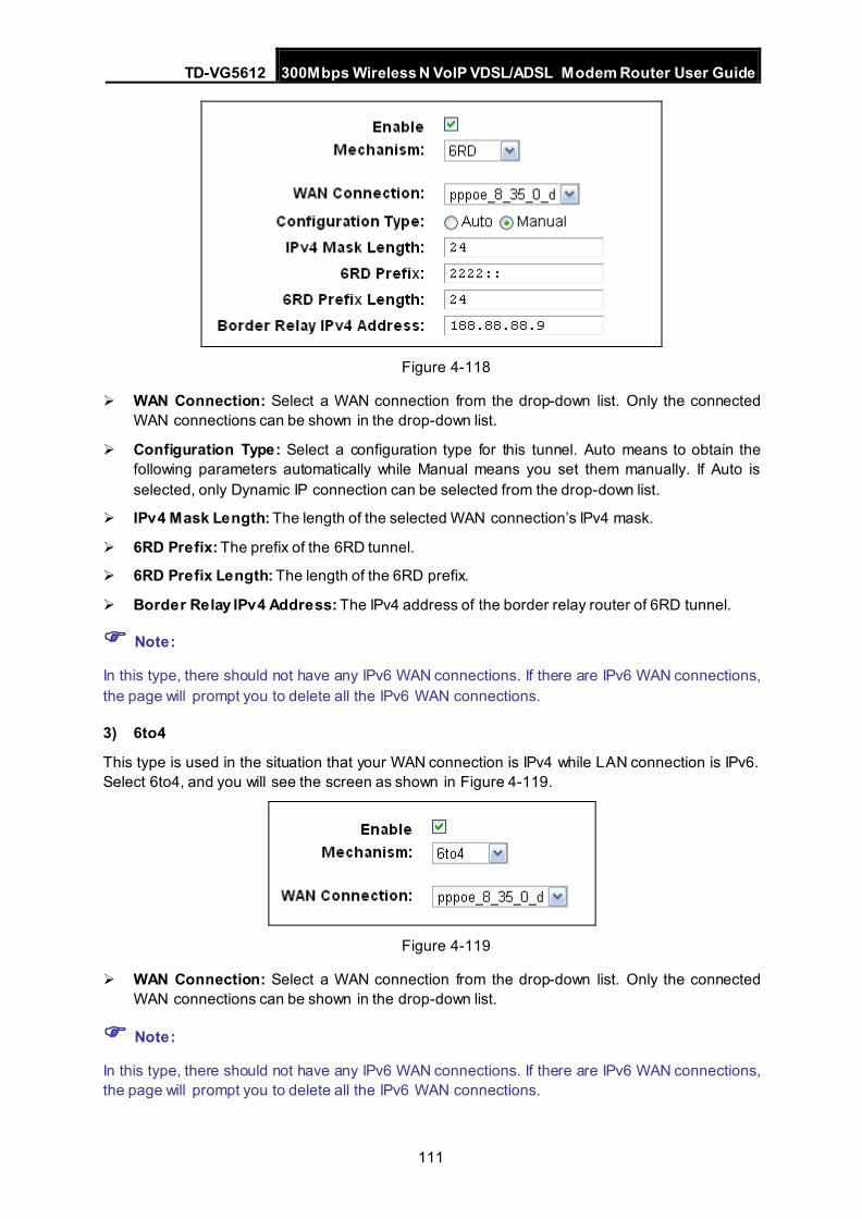
TD-VG5612 300Mbps Wireless N VoIP VDSL/ADSL Modem Router User Guide
111
Figure 4-118
WAN Connection: Select a WAN connection from the drop-down list. Only the connected WAN connections can be shown in the drop-down list.
Configuration Type: Select a configuration type for this tunnel. Auto means to obtain the following parameters automatically while Manual means you set them manually. If Auto is selected, only Dynamic IP connection can be selected from the drop-down list.
IPv4 Mask Length: The length of the selected WAN connection’s IPv4 mask.
6RD Prefix: The prefix of the 6RD tunnel.
6RD Prefix Length: The length of the 6RD prefix.
Border Relay IPv4 Address: The IPv4 address of the border relay router of 6RD tunnel.
Note:
In this type, there should not have any IPv6 WAN connections. If there are IPv6 WAN connections, the page will prompt you to delete all the IPv6 WAN connections.
3) 6to4
This type is used in the situation that your WAN connection is IPv4 while LAN connection is IPv6. Select 6to4, and you will see the screen as shown in Figure 4-119.
Figure 4-119
WAN Connection: Select a WAN connection from the drop-down list. Only the connected WAN connections can be shown in the drop-down list.
Note:
In this type, there should not have any IPv6 WAN connections. If there are IPv6 WAN connections, the page will prompt you to delete all the IPv6 WAN connections.
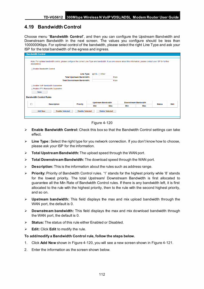
TD-VG5612 300Mbps Wireless N VoIP VDSL/ADSL Modem Router User Guide
112
4.19 Bandwidth Control
Choose menu “Bandwidth Control”, and then you can configure the Upstream Bandwidth and Downstream Bandwidth in the next screen. The values you configure should be less than 1000000Kbps. For optimal control of the bandwidth, please select the right Line Type and ask your ISP for the total bandwidth of the egress and ingress.
Figure 4-120
Enable Bandwidth Control: Check this box so that the Bandwidth Control settings can take effect.
Line Type: Select the right type for you network connection. If you don’t know how to choose, please ask your ISP for the information.
Total Upstream Bandwidth: The upload speed through the WAN port.
Total Downstream Bandwidth: The download speed through the WAN port.
Description: This is the information about the rules such as address range.
Priority: Priority of Bandwidth Control rules. ‘1’ stands for the highest priority while ‘8’ stands for the lowest priority. The total Upstream/ Downstream Bandwidth is first allocated to guarantee all the Min Rate of Bandwidth Control rules. If there is any bandwidth left, it is first allocated to the rule with the highest priority, then to the rule with the second highest priority, and so on.
Upstream bandwidth: This field displays the max and mix upload bandwidth through the WAN port, the default is 0.
Downstream bandwidth: This field displays the max and mix download bandwidth through the WAN port, the default is 0.
Status: The status of this rule either Enabled or Disabled.
Edit: Click Edit to modify the rule.
To add/modify a Bandwidth Control rule, follow the steps below.
1. Click Add New shown in Figure 4-120, you will see a new screen shown in Figure 4-121.
2. Enter the information as the screen shown below.
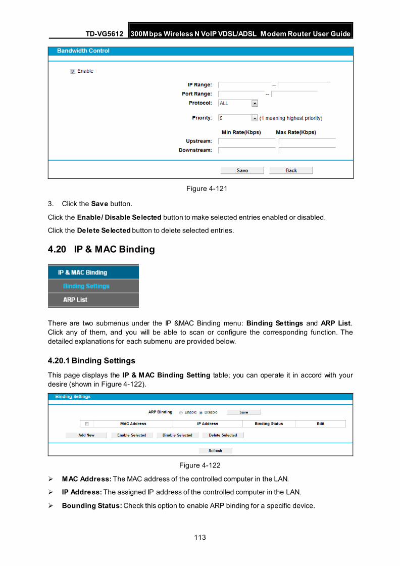
TD-VG5612 300Mbps Wireless N VoIP VDSL/ADSL Modem Router User Guide
113
Figure 4-121
3. Click the Save button.
Click the Enable/ Disable Selected button to make selected entries enabled or disabled.
Click the Delete Selected button to delete selected entries.
4.20 IP & MAC Binding
There are two submenus under the IP &MAC Binding menu: Binding Settings and ARP List. Click any of them, and you will be able to scan or configure the corresponding function. The detailed explanations for each submenu are provided below.
4.20.1 Binding Settings This page displays the IP & MAC Binding Setting table; you can operate it in accord with your desire (shown in Figure 4-122).
Figure 4-122
MAC Address: The MAC address of the controlled computer in the LAN.
IP Address: The assigned IP address of the controlled computer in the LAN.
Bounding Status: Check this option to enable ARP binding for a specific device.
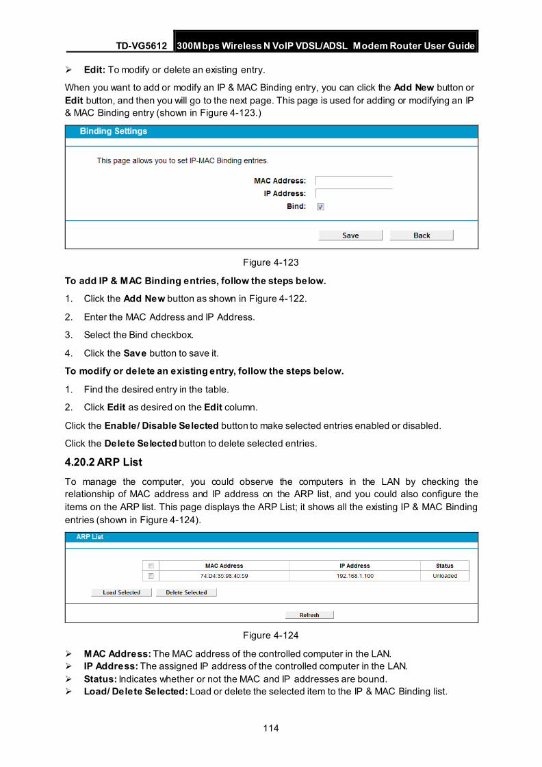
TD-VG5612 300Mbps Wireless N VoIP VDSL/ADSL Modem Router User Guide
114
Edit: To modify or delete an existing entry.
When you want to add or modify an IP & MAC Binding entry, you can click the Add New button or Edit button, and then you will go to the next page. This page is used for adding or modifying an IP & MAC Binding entry (shown in Figure 4-123.)
Figure 4-123
To add IP & MAC Binding entries, follow the steps below.
1. Click the Add New button as shown in Figure 4-122.
2. Enter the MAC Address and IP Address.
3. Select the Bind checkbox.
4. Click the Save button to save it.
To modify or delete an existing entry, follow the steps below.
1. Find the desired entry in the table.
2. Click Edit as desired on the Edit column.
Click the Enable/ Disable Selected button to make selected entries enabled or disabled.
Click the Delete Selected button to delete selected entries.
4.20.2 ARP List To manage the computer, you could observe the computers in the LAN by checking the relationship of MAC address and IP address on the ARP list, and you could also configure the items on the ARP list. This page displays the ARP List; it shows all the existing IP & MAC Binding entries (shown in Figure 4-124).
Figure 4-124
MAC Address: The MAC address of the controlled computer in the LAN. IP Address: The assigned IP address of the controlled computer in the LAN. Status: Indicates whether or not the MAC and IP addresses are bound. Load/ Delete Selected: Load or delete the selected item to the IP & MAC Binding list.
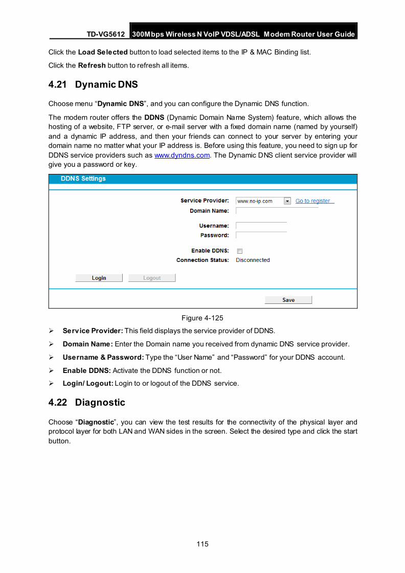
TD-VG5612 300Mbps Wireless N VoIP VDSL/ADSL Modem Router User Guide
115
Click the Load Selected button to load selected items to the IP & MAC Binding list.
Click the Refresh button to refresh all items.
4.21 Dynamic DNS
Choose menu “Dynamic DNS”, and you can configure the Dynamic DNS function.
The modem router offers the DDNS (Dynamic Domain Name System) feature, which allows the hosting of a website, FTP server, or e-mail server with a fixed domain name (named by yourself) and a dynamic IP address, and then your friends can connect to your server by entering your domain name no matter what your IP address is. Before using this feature, you need to sign up for DDNS service providers such as www.dyndns.com. The Dynamic DNS client service provider will give you a password or key.
Figure 4-125
Service Provider: This field displays the service provider of DDNS.
Domain Name: Enter the Domain name you received from dynamic DNS service provider.
Username & Password: Type the “User Name” and “Password” for your DDNS account.
Enable DDNS: Activate the DDNS function or not.
Login/ Logout: Login to or logout of the DDNS service.
4.22 Diagnostic
Choose “Diagnostic”, you can view the test results for the connectivity of the physical layer and protocol layer for both LAN and WAN sides in the screen. Select the desired type and click the start button.
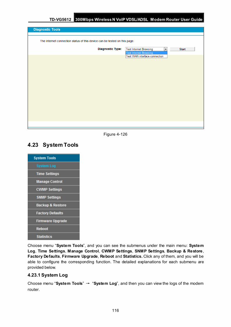
TD-VG5612 300Mbps Wireless N VoIP VDSL/ADSL Modem Router User Guide
116
Figure 4-126
4.23 System Tools
Choose menu “System Tools”, and you can see the submenus under the main menu: System Log, Time Settings, Manage Control, CWMP Settings, SNMP Settings, Backup & Restore , Factory Defaults, Firmware Upgrade, Reboot and Statistics. Click any of them, and you will be able to configure the corresponding function. The detailed explanations for each submenu are provided below.
4.23.1 System Log Choose menu “System Tools” → “System Log”, and then you can view the logs of the modem router.
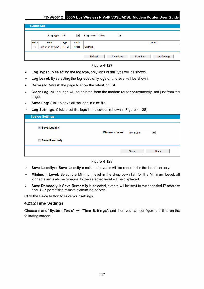
TD-VG5612 300Mbps Wireless N VoIP VDSL/ADSL Modem Router User Guide
117
Figure 4-127
Log Type: By selecting the log type, only logs of this type will be shown.
Log Level: By selecting the log level, only logs of this level will be shown.
Refresh: Refresh the page to show the latest log list.
Clear Log: All the logs will be deleted from the modem router permanently, not just from the page.
Save Log: Click to save all the logs in a txt file.
Log Settings: Click to set the logs in the screen (shown in Figure 4-128).
Figure 4-128
Save Locally: If Save Locally is selected, events will be recorded in the local memory.
Minimum Level: Select the Minimum level in the drop-down list, for the Minimum Level, all logged events above or equal to the selected level will be displayed.
Save Remotely: If Save Remotely is selected, events will be sent to the specified IP address and UDP port of the remote system log server.
Click the Save button to save your settings.
4.23.2 Time Settings Choose menu “System Tools” → “Time Settings”, and then you can configure the time on the following screen.
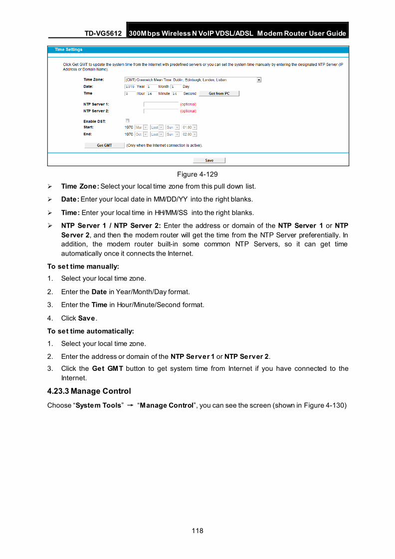
TD-VG5612 300Mbps Wireless N VoIP VDSL/ADSL Modem Router User Guide
118
Figure 4-129
Time Zone: Select your local time zone from this pull down list.
Date: Enter your local date in MM/DD/YY into the right blanks.
Time: Enter your local time in HH/MM/SS into the right blanks.
NTP Server 1 / NTP Server 2: Enter the address or domain of the NTP Server 1 or NTP Server 2, and then the modem router will get the time from the NTP Server preferentially. In addition, the modem router built-in some common NTP Servers, so it can get time automatically once it connects the Internet.
To set time manually: 1. Select your local time zone.
2. Enter the Date in Year/Month/Day format.
3. Enter the Time in Hour/Minute/Second format.
4. Click Save .
To set time automatically: 1. Select your local time zone.
2. Enter the address or domain of the NTP Server 1 or NTP Server 2.
3. Click the Get GMT button to get system time from Internet if you have connected to the Internet.
4.23.3 Manage Control Choose “System Tools” → “Manage Control”, you can see the screen (shown in Figure 4-130)
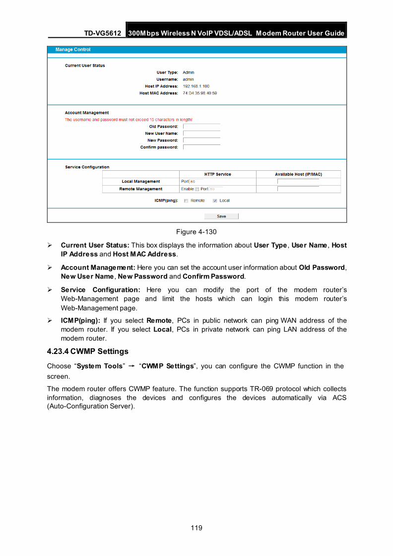
TD-VG5612 300Mbps Wireless N VoIP VDSL/ADSL Modem Router User Guide
119
Figure 4-130
Current User Status: This box displays the information about User Type , User Name , Host IP Address and Host MAC Address.
Account Management: Here you can set the account user information about Old Password, New User Name , New Password and Confirm Password.
Service Configuration: Here you can modify the port of the modem router’s Web-Management page and limit the hosts which can login this modem router’s Web-Management page.
ICMP(ping): If you select Remote, PCs in public network can ping WAN address of the modem router. If you select Local, PCs in private network can ping LAN address of the modem router.
4.23.4 CWMP Settings
Choose “System Tools” → “CWMP Settings”, you can configure the CWMP function in the screen.
The modem router offers CWMP feature. The function supports TR-069 protocol which collects information, diagnoses the devices and configures the devices automatically via ACS (Auto-Configuration Server).
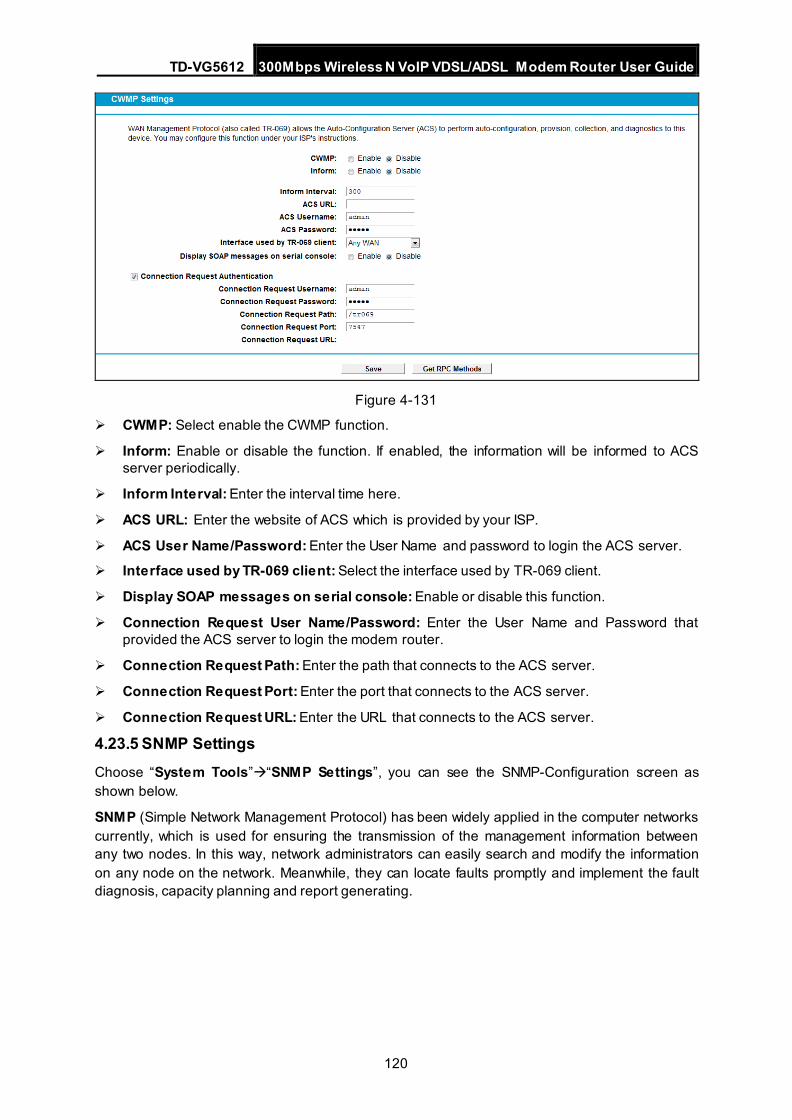
TD-VG5612 300Mbps Wireless N VoIP VDSL/ADSL Modem Router User Guide
120
Figure 4-131
CWMP: Select enable the CWMP function.
Inform: Enable or disable the function. If enabled, the information will be informed to ACS server periodically.
Inform Interval: Enter the interval time here.
ACS URL: Enter the website of ACS which is provided by your ISP.
ACS User Name/Password: Enter the User Name and password to login the ACS server.
Interface used by TR-069 client: Select the interface used by TR-069 client.
Display SOAP messages on serial console: Enable or disable this function.
Connection Request User Name/Password: Enter the User Name and Password that provided the ACS server to login the modem router.
Connection Request Path: Enter the path that connects to the ACS server.
Connection Request Port: Enter the port that connects to the ACS server.
Connection Request URL: Enter the URL that connects to the ACS server.
4.23.5 SNMP Settings Choose “System Tools”“SNMP Settings”, you can see the SNMP-Configuration screen as shown below.
SNMP (Simple Network Management Protocol) has been widely applied in the computer networks currently, which is used for ensuring the transmission of the management information between any two nodes. In this way, network administrators can easily search and modify the information on any node on the network. Meanwhile, they can locate faults promptly and implement the fault diagnosis, capacity planning and report generating.
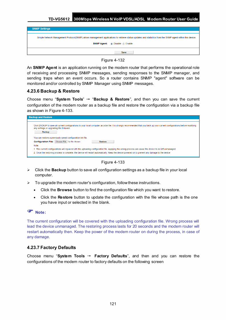
TD-VG5612 300Mbps Wireless N VoIP VDSL/ADSL Modem Router User Guide
121
Figure 4-132
An SNMP Agent is an application running on the modem router that performs the operational role of receiving and processing SNMP messages, sending responses to the SNMP manager, and sending traps when an event occurs. So a router contains SNMP "agent" software can be monitored and/or controlled by SNMP Manager using SNMP messages.
4.23.6 Backup & Restore Choose menu “System Tools” → “Backup & Restore”, and then you can save the current configuration of the modem router as a backup file and restore the configuration via a backup file as shown in Figure 4-133.
Figure 4-133
Click the Backup button to save all configuration settings as a backup file in your local computer.
To upgrade the modem router's configuration, follow these instructions.
• Click the Browse button to find the configuration file which you want to restore.
• Click the Restore button to update the configuration with the file whose path is the one you have input or selected in the blank.
Note:
The current configuration will be covered with the uploading configuration file. Wrong process will lead the device unmanaged. The restoring process lasts for 20 seconds and the modem router will restart automatically then. Keep the power of the modem router on during the process, in case of any damage.
4.23.7 Factory Defaults
Choose menu “System Tools → Factory Defaults”, and then and you can restore the configurations of the modem router to factory defaults on the following screen
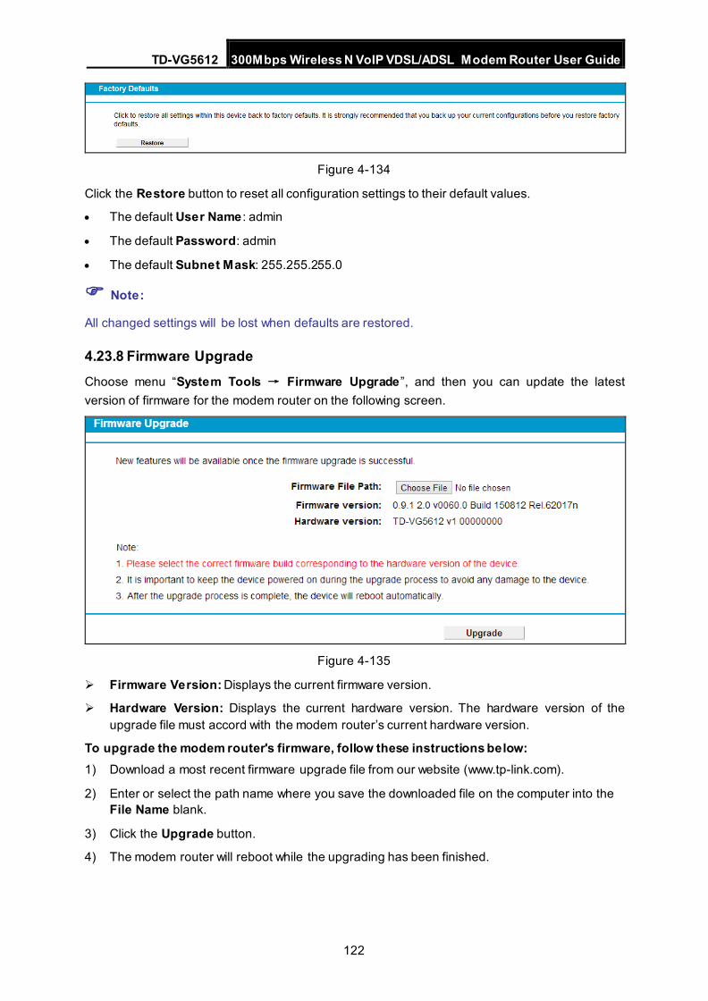
TD-VG5612 300Mbps Wireless N VoIP VDSL/ADSL Modem Router User Guide
122
Figure 4-134
Click the Restore button to reset all configuration settings to their default values.
• The default User Name : admin
• The default Password: admin
• The default Subnet Mask: 255.255.255.0
Note:
All changed settings will be lost when defaults are restored.
4.23.8 Firmware Upgrade Choose menu “System Tools → Firmware Upgrade”, and then you can update the latest version of firmware for the modem router on the following screen.
Figure 4-135
Firmware Version: Displays the current firmware version.
Hardware Version: Displays the current hardware version. The hardware version of the upgrade file must accord with the modem router’s current hardware version.
To upgrade the modem router's firmware, follow these instructions below: 1) Download a most recent firmware upgrade file from our website (www.tp-link.com).
2) Enter or select the path name where you save the downloaded file on the computer into the File Name blank.
3) Click the Upgrade button.
4) The modem router will reboot while the upgrading has been finished.
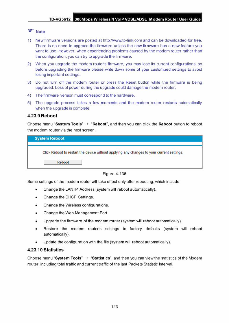
TD-VG5612 300Mbps Wireless N VoIP VDSL/ADSL Modem Router User Guide
123
Note:
1) New firmware versions are posted at http://www.tp-link.com and can be downloaded for free. There is no need to upgrade the firmware unless the new firmware has a new feature you want to use. However, when experiencing problems caused by the modem router rather than the configuration, you can try to upgrade the firmware.
2) When you upgrade the modem router's firmware, you may lose its current configurations, so before upgrading the firmware please write down some of your customized settings to avoid losing important settings.
3) Do not turn off the modem router or press the Reset button while the firmware is being upgraded. Loss of power during the upgrade could damage the modem router.
4) The firmware version must correspond to the hardware.
5) The upgrade process takes a few moments and the modem router restarts automatically when the upgrade is complete.
4.23.9 Reboot Choose menu “System Tools” → “Reboot”, and then you can click the Reboot button to reboot the modem router via the next screen.
Figure 4-136
Some settings of the modem router will take effect only after rebooting, which include
• Change the LAN IP Address (system will reboot automatically).
• Change the DHCP Settings.
• Change the Wireless configurations.
• Change the Web Management Port.
• Upgrade the firmware of the modem router (system will reboot automatically).
• Restore the modem router's settings to factory defaults (system will reboot automatically).
• Update the configuration with the file (system will reboot automatically).
4.23.10 Statistics Choose menu “System Tools” → “Statistics”, and then you can view the statistics of the Modem router, including total traffic and current traffic of the last Packets Statistic Interval.
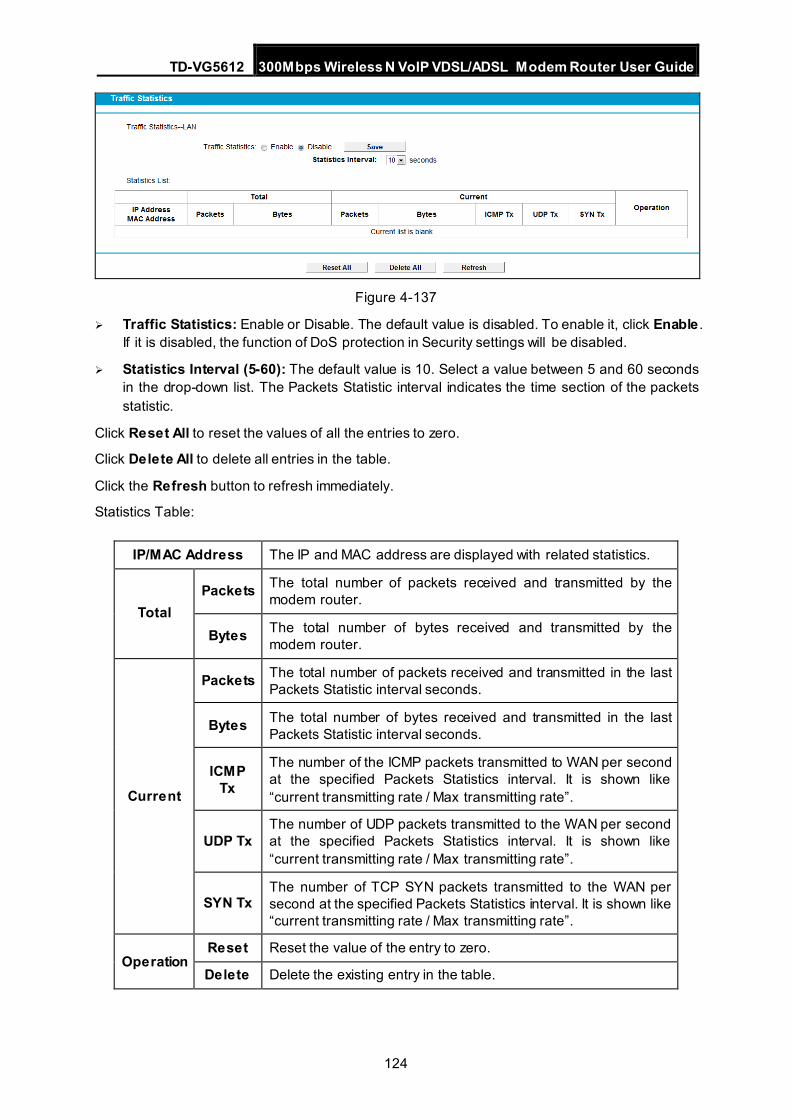
TD-VG5612 300Mbps Wireless N VoIP VDSL/ADSL Modem Router User Guide
124
Figure 4-137
Traffic Statistics: Enable or Disable. The default value is disabled. To enable it, click Enable . If it is disabled, the function of DoS protection in Security settings will be disabled.
Statistics Interval (5-60): The default value is 10. Select a value between 5 and 60 seconds in the drop-down list. The Packets Statistic interval indicates the time section of the packets statistic.
Click Reset All to reset the values of all the entries to zero.
Click Delete All to delete all entries in the table.
Click the Refresh button to refresh immediately.
Statistics Table:
IP/MAC Address The IP and MAC address are displayed with related statistics.
Total Packets The total number of packets received and transmitted by the
modem router.
Bytes The total number of bytes received and transmitted by the modem router.
Current
Packets The total number of packets received and transmitted in the last Packets Statistic interval seconds.
Bytes The total number of bytes received and transmitted in the last Packets Statistic interval seconds.
ICMP Tx
The number of the ICMP packets transmitted to WAN per second at the specified Packets Statistics interval. It is shown like “current transmitting rate / Max transmitting rate”.
UDP Tx The number of UDP packets transmitted to the WAN per second at the specified Packets Statistics interval. It is shown like “current transmitting rate / Max transmitting rate”.
SYN Tx The number of TCP SYN packets transmitted to the WAN per second at the specified Packets Statistics interval. It is shown like “current transmitting rate / Max transmitting rate”.
Operation Reset Reset the value of the entry to zero.
Delete Delete the existing entry in the table.
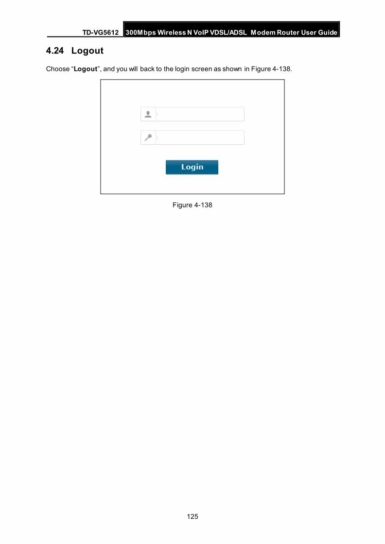
TD-VG5612 300Mbps Wireless N VoIP VDSL/ADSL Modem Router User Guide
125
4.24 Logout
Choose “Logout”, and you will back to the login screen as shown in Figure 4-138.
Figure 4-138
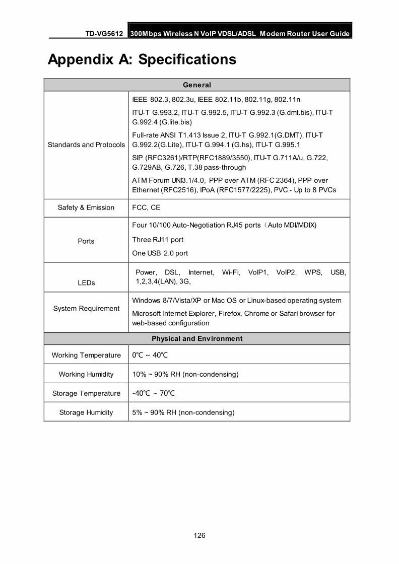
TD-VG5612 300Mbps Wireless N VoIP VDSL/ADSL Modem Router User Guide
126
Appendix A: Specifications General
Standards and Protocols
IEEE 802.3, 802.3u, IEEE 802.11b, 802.11g, 802.11n
ITU-T G.993.2, ITU-T G.992.5, ITU-T G.992.3 (G.dmt.bis), ITU-T G.992.4 (G.lite.bis)
Full-rate ANSI T1.413 Issue 2, ITU-T G.992.1(G.DMT), ITU-T G.992.2(G.Lite), ITU-T G.994.1 (G.hs), ITU-T G.995.1
SIP (RFC3261)/RTP(RFC1889/3550), ITU-T G.711A/u, G.722, G.729AB, G.726, T.38 pass-through
ATM Forum UNI3.1/4.0, PPP over ATM (RFC 2364), PPP over Ethernet (RFC2516), IPoA (RFC1577/2225), PVC - Up to 8 PVCs
Safety & Emission FCC, CE
Ports
Four 10/100 Auto-Negotiation RJ45 ports(Auto MDI/MDIX)
Three RJ11 port
One USB 2.0 port
LEDs Power, DSL, Internet, Wi-Fi, VoIP1, VoIP2, WPS, USB, 1,2,3,4(LAN), 3G,
System Requirement Windows 8/7/Vista/XP or Mac OS or Linux-based operating system
Microsoft Internet Explorer, Firefox, Chrome or Safari browser for web-based configuration
Physical and Environment
Working Temperature 0℃ ~ 40℃
Working Humidity 10% ~ 90% RH (non-condensing)
Storage Temperature -40℃ ~ 70℃
Storage Humidity 5% ~ 90% RH (non-condensing)
TD-VG5612 300Mbps Wireless N VoIP VDSL/ADSL Modem Router User Guide
127
Appendix B: Troubleshooting T1. How do I restore my modem router’s configuration to its factory default
settings?
With the modem router powered on, press and hold the RESET button on the rear panel for 8 to 10 seconds before releasing it.
Note :
Once the modem router is reset, the current configuration settings will be lost and you will need to re-configure the router.
T2. What can I do if I don’t know or forget my password? 1) Restore the modem router’s configuration to its factory default settings. If you don’t know how
to do that, please refer to T1. 2) Use the default user name and password: admin, admin. 3) Try to configure your modem router once again by following the instructions in 3.2 Quick
Installation Guide.
T3. What can I do if I cannot access the web-based configuration page? 1) Configure your computer’s IP Address.
For Mac OS X Click the Apple icon on the upper left corner of the screen.
Go to “System Preferences -> Network”.
Select Airport on the left menu bar, and then click Advanced for wireless configuration; or select Ethernet for wired configuration.
In the Con-figure IPv4 box under TCP/IP, select Using DHCP.
Click Apply to save the settings.
For Windows 7 Click “Start -> Control Panel -> Network and Internet -> View network status -> Change
adapter settings”.
Right-click Wireless Network Connection (or Local Area Connection), and then click Properties.
Select Internet Protocol Version 4 (TCP/IPv4), and then click Properties.
Select Obtain an IP address automatically and Obtain DNS server address automatically. Then click OK.
For Windows XP Click “Start -> Control Panel -> Network and Internet Connections -> Network
Connections”.
Right-click Wireless Network Connection (or Local Area Connection), and then click Properties.
Select Internet Protocol (TCP/IP), and then click Properties.
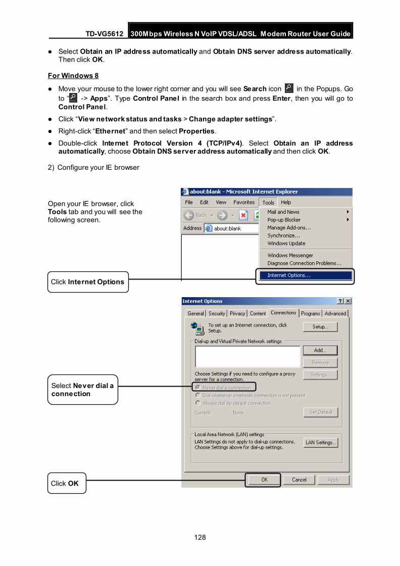
TD-VG5612 300Mbps Wireless N VoIP VDSL/ADSL Modem Router User Guide
128
Select Obtain an IP address automatically and Obtain DNS server address automatically. Then click OK.
For Windows 8
Move your mouse to the lower right corner and you will see Search icon in the Popups. Go to “ -> Apps”. Type Control Panel in the search box and press Enter, then you will go to Control Panel.
Click “View network status and tasks > Change adapter settings”.
Right-click “Ethernet” and then select Properties.
Double-click Internet Protocol Version 4 (TCP/IPv4). Select Obtain an IP address automatically, choose Obtain DNS server address automatically and then click OK.
2) Configure your IE browser
Open your IE browser, click Tools tab and you will see the following screen.
Click Internet Options
Click OK
Select Never dial a connection
TD-VG5612 300Mbps Wireless N VoIP VDSL/ADSL Modem Router User Guide
129
Now, try to log on to the Web-based management page again after the above settings have been configured. If you still cannot access the configuration page, please restore your modem router’s factory default settings and reconfigure your modem router following the instructions in 3.2 Quick Installation Guide. Please feel free to contact our Technical Support if the problem still exists.
T4. What can I do if I cannot access the Internet? 1) Check to see if all the connectors are connected well, including the telephone line, Ethernet
cables and power adapter.
2) Check to see if you can log on to the Web-Management page of the modem router. If you can, try the following steps. If you cannot, please set your computer referring to T3 then try to see if you can access the Internet. If the problem persists, please go to the next step.
3) Consult your ISP and make sure all the VPI/VCI, Connection Type, account username and password are correct. If there are any mistakes, please correct the settings and try again.
4) If you still cannot access the Internet, please restore your modem router to its factory default settings and reconfigure your modem router by following the instructions in 3.2 Quick Installation Guide.
5) Please contact our Technical Support if the problem still exists.
Note:
For more details about Troubleshooting and Technical Support contact information, please refer to the support page at www.tp-link.com or the Technical Support card found in your package.
T5. What can I do if I don’t know how to configure USB device for USB Voice Mail function?
a) Plug an external USB hard drive or USB flash disk into the USB port labeled “USB 1/2” on the Modem Router. The free space of the plugged USB device should be more than 4MB.
b) Insert the provided Resource CD into CD-ROM drive of your computer.
c) Please select your product model and click Start Setup.
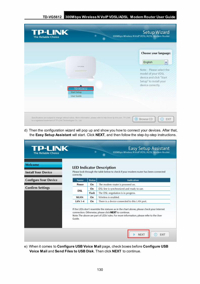
TD-VG5612 300Mbps Wireless N VoIP VDSL/ADSL Modem Router User Guide
130
d) Then the configuration wizard will pop up and show you how to connect your devices. After that,
the Easy Setup Assistant will start. Click NEXT, and then follow the step-by-step instructions.
e) When it comes to Configure USB Voice Mail page, check boxes before Configure USB
Voice Mail and Send Files to USB Disk. Then click NEXT to continue.
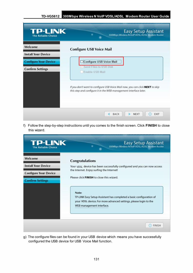
TD-VG5612 300Mbps Wireless N VoIP VDSL/ADSL Modem Router User Guide
131
f) Follow the step-by-step instructions until you comes to the finish screen. Click FINISH to close this wizard.
g) The configure files can be found in your USB device which means you have successfully configured the USB device for USB Voice Mail function.
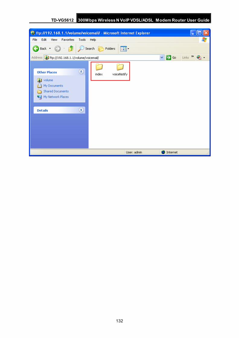
TD-VG5612 300Mbps Wireless N VoIP VDSL/ADSL Modem Router User Guide
132
TD-VG5612 300Mbps Wireless N VoIP VDSL/ADSL Modem Router User Guide
133
Appendix C: Telephony Features This section introduces what the following features are used for.
Call Holding
This feature allows you to put a call on hold, in which case the call is not ended but no verbal communication is available.
To put a call on hold, press the FLASH button. To return to the original call, press the FLASH button again.
Call Transfer
This feature allows you to redirect the current call to another phone by using the FLASH button and dialing the destination number.
To transfer a call, please follow the steps below:
1. Press FLASH button to put the current call on hold.
2. Dial the destination number.
Note: To quit the transfer, press the FLASH button again to return to the original call before hearing the ringback tone.
3. Hang up when hearing the ringback tone or wait for the newly called party to answer and then hang up. Now the call is successfully transferred.
Call Waiting
With this feature enabled, if a calling party places a call to you while you are busy, you are able to suspend the current call and switch to the new incoming call.
To switch to the new incoming call, press FLASH followed by the number 2. The first call will be automatically put on hold. You can switch between the two calls by pressing FLASH followed by the number 2.
USB Voice Mail
With this feature enabled, the caller will be prompted to leave a voice message upon the call or when there is no response for a certain time.
Call Forwarding
This feature allows an incoming call to be redirected to a specified party. There are two call forwarding features, including Call Forwarding Unconditionally and Call Forwarding on No Answer.
With Call Forwarding Unconditionally enabled, no matter whether the called party is busy or not, the incoming call will be redirected to the specified party.
With Call Forwarding on No Answer enabled, the incoming call will be redirected to the specified party when there is no response for a certain time.
Anonymous Calling
This feature allows you to make a call without your phone number or ID being displayed on the called party's phone.
Anonymous Call Blocking
With this feature enabled, all anonymous calls will be blocked.
TD-VG5612 300Mbps Wireless N VoIP VDSL/ADSL Modem Router User Guide
134
Speed Dial
This feature allows you to create short numbers for your frequently used telephone numbers to make your dialing more convenient. You just need to press one or two digits and the key # instead of the original phone number to make a call.
Warm Line
With this feature enabled, a call will be automatically directed to a specified party without taking any additional action when the phone goes off-hook for a certain time. To use this feature, you need to set warm line numbers first on the web management page.
DND (Do Not Disturb)
With this feature enabled, all the incoming calls will be blocked and the caller will hear the busy tone.
Three-way Call
This feature allows three people to communicate at the same time.
To set up a three-way call, please follow the steps below:
1. Press the FLASH button to put the first call on hold.
2. Dial the destination number.
3. Wait for the third party to answer and then press FLASH followed by the number 3. Now the three-way call is successfully set up.
4. To drop yourself out of the call, simply hang up.
A three-way call can also be set up during a call with Call Waiting enabled. When hearing the call waiting tone during a call, press FLASH followed by the number 3.
Note: The call will end if the initiator of the three-way call hangs up. However, the call will not end if anyone of the other two parties hangs up. The left two parties remain connected to each other.