Embed Size (px)
Citation preview

IPAQ C330/R330IPAQ C330/R330IPAQ C330/R330IPAQ C330/R330 Technical DatasheetTechnical DatasheetTechnical DatasheetTechnical Datasheet
Smart 2-wire universal transmitter with NFC technology
• NFC - Configuration of the transmitter via a portable device such as a smartphone• High accuracy and long-term stability• Universal input• Efficient PC-configuration without external power
© INOR 03/2019 - 4007542201 - TD IPAQ 330 R01 en
The documentation is only complete when used in combination with the relevant documentation for the sensor.

CONTENTS
2 www.inor.com 03/2019 - 4007542201 - TD IPAQ 330 R01 en
IPAQ C330/R330
1 Product features 3
1.1 Smart 2-wire universal temperature transmitter with NFC technology ........................ 31.2 Options and variants......................................................................................................... 51.3 Measuring principles........................................................................................................ 6
1.3.1 Resistance temperature sensor ............................................................................................. 61.3.2 Thermocouples ....................................................................................................................... 7
2 Technical data 8
2.1 Technical data................................................................................................................... 82.2 Dimensions ..................................................................................................................... 132.3 Temperature data for areas with potentially explosive atmospheres .......................... 142.4 Output load diagram....................................................................................................... 152.5 Electrical data for outputs and inputs............................................................................ 162.6 RTD and T/C accuracy table ........................................................................................... 17
3 Installation 19
3.1 Intended use ................................................................................................................... 193.2 In-head transmitter........................................................................................................ 193.3 Rail-mount transmitter .................................................................................................. 21
4 Electrical connections 22
4.1 Notes on installation ...................................................................................................... 224.2 Electrical connections of in-head transmitter............................................................... 224.3 Connection diagram of in-head transmitter .................................................................. 234.4 Connection diagram of in-head transmitter (intrinsically safe).................................... 244.5 Electrical connections of rail-mount transmitter.......................................................... 254.6 Connection diagram of rail-mount transmitter............................................................. 264.7 Connection diagram of rail-mount transmitter (intrinsically safe)............................... 26
5 Order information 27
5.1 Order code ...................................................................................................................... 27
6 Notes 30

PRODUCT FEATURES 1
3
IPAQ C330/R330
www.inor.com03/2019 - 4007542201 - TD IPAQ 330 R01 en
1.1 Smart 2-wire universal temperature transmitter with NFC technology
The IPAQ 330 signal conditioner is a universal, isolated 2-wire transmitter for temperature, resistance or voltage measurements in an industrial environment.
The IPAQ 330 series consists of two different versions. C330 is primarily intended to be mounted in a DIN-B housing whereas R330 is the rail-mount version.
NFC features enables wireless communication and configuration between transmitter and a portable device such a smartphone. Typical characteristics are the high accuracy, stability and reliability combined with a robust housing.
1 In-head transmitter2 Rail-mount transmitter

1 PRODUCT FEATURES
4
IPAQ C330/R330
www.inor.com 03/2019 - 4007542201 - TD IPAQ 330 R01 en
HighlightsHigh measurement accuracyHigh measurement accuracyHigh measurement accuracyHigh measurement accuracy
• Long-term stability: drift over 5 years is the maximum of ±0.1°C or ±0.1% of span• High precision: ±0.08°C / ±0.18°F or 0.08% of span (example Pt100)• Low temperature drift ±0.01°C per °C or ±0.01% of span per °C
High reliabilityHigh reliabilityHigh reliabilityHigh reliability
• Robust design: 10g vibrations, 98% RH and robust terminals
High safetyHigh safetyHigh safetyHigh safety
• NAMUR compliant to NE 21, NE 43 and NE 107• ATEX and IECEx (intrinsically safe)
High user efficiencyHigh user efficiencyHigh user efficiencyHigh user efficiency
• NFC - Wireless communication enables easy configuration with a portable device such as asmartphone.
• Ability to communicate via Bluetooth® - requires the Bluetooth® interface - ICON-BT• Callendar – Van Dusen linearization• Run-time watch• Configuration history and the ability to read back the last two configurations from memory.• Min and Max power supply memory• Min and Max ambient temperature memory• Passoword protection
Industries Typical industrial applications are in:
• Chemicals• Oil & Gas• Power• Iron, Steel & Metal• Pulp & Paper• Food & Beverage• Pharmaceuticals

PRODUCT FEATURES 1
5
IPAQ C330/R330
www.inor.com03/2019 - 4007542201 - TD IPAQ 330 R01 en
1.2 Options and variants
C330: in-head transmitter
R330: rail-mount transmitter
Different versions of the IPAQ 330
The C330 is a smart, universal 2-wire in-head transmitter for temperature, resistance or voltage measurements in an industrial environment.The C330 is optionally available in an intrinsically safe version for use in zone 0, 1 and 2.All versions are intended for installation in a "B connection head" or larger according toDIN EN 50446.NFC applies only to later versions of C330, see table below.
The R330 is a smart, universal 2-wire rail-mount transmitter for temperature, resistance or voltage measurements in an industrial environment.The R330 is optionally available in an intrinsically safe version for use in zone 0, 1 and 2.All versions are intended for installation on a rail according to EN 60715 / DIN 50022.NFC applies only to later versions of R330, see table below.
IPAQ Part Number NFC
C330 / C330X 70C3300010 / 70C330X010 No
70C3300012 / 70C330X012 Yes
R330 / R330X 70R3300010 / 70R330X010 No
70R3300012 / 70R330X012 Yes

1 PRODUCT FEATURES
6
IPAQ C330/R330
www.inor.com 03/2019 - 4007542201 - TD IPAQ 330 R01 en
1.3 Measuring principles
The kind of the measuring principle depends on the measuring insert that you combine with the transmitter. In matters of the thermometer type the manufacturer offers two different measuring inserts, either with a resistance thermometer or with a thermocouple. This transmitter supports both types.
1.3.1 Resistance temperature sensor
The measuring insert with a temperature-sensitive sensor made from a platinum(Pt) RTD, whose value at 0°C / +32°F is 100 Ω. That is where the name "Pt100" comes from.
It is generally valid that the electric resistance of metals increases according to a mathematical function as the temperature rises. This effect is taken advantage of by resistance temperature sensors to measure temperature. The "Pt100" temperature sensors features a measuring resistance with defined characteristics, standardised in IEC 60751. The same is true for the tolerances. The average temperature coefficient of a Pt100 is 3.85 x 10⁻³ K-1 in the range from 0...+100°C / +32...+212°F.
During operation, a constant current I (≤ 1 mA) flows through the Pt100 RTD, which brings about a voltage drop U. The resistance R is calculated using Ohm's Law (R=U/I). As the voltage drop U at 0°C / +32°F is 100 mV, the resulting resistance of the Pt100 temperature assembly is 100 Ω (100 mV / 1 mA = 100 Ω).
Figure 1-1: Pt100 resistance temperature sensor at 0°C / +32°F, schematic.
1 Pt100 RTD2 Voltage meter3 Current source

PRODUCT FEATURES 1
7
IPAQ C330/R330
www.inor.com03/2019 - 4007542201 - TD IPAQ 330 R01 en
1.3.2 Thermocouples
The thermocouple features two electric conductors made from different metals, connected at one end. Each free end is connected to a compensation cable which is then connected to a millivolt meter. This circuitry forms a "thermal circuit". The point at which the two electric conductors connect is called the measuring point and the point at which the compensation cables connect to the conductors of the millivolt meter is called the cold junction.
If the measuring point of this thermal circuit is heated up, a small electrical voltage (thermal voltage) can be measured. If, however, the measuring point and the cold junction are at the same temperature, no thermoelectric voltage is generated. The degree of thermoelectric voltage, also known as electromotive force (EMF), depends on the thermocouple material and the extent of the temperature difference between the measuring point and the cold junction. It can be measured using the millivolt meter with no auxiliary power.
Simply put, the thermocouple behaves like a battery, the voltage of which also increases as the temperature rises.
The characteristic curves and tolerances of commercially available thermocouples are standardised in IEC 60584.
Figure 1-2: Thermocouple measuring circuit, schematic.
1 Measuring point t1 (hot junction)2 Thermocouple3 Transition junction t24 Compensation cable / extension cable5 Reference junction t3 (cold junction)6 Copper conductor7 Voltage meter Uth

2 TECHNICAL DATA
8
IPAQ C330/R330
www.inor.com 03/2019 - 4007542201 - TD IPAQ 330 R01 en
2.1 Technical data
• The following data is provided for general applications. If you require data that is more relevant to your specific application, please contact us or your local sales office.
• Additional information (certificates, special tools, software,...) and complete product documentation can be downloaded free of charge from the website.
Measuring systemApplication range Temperature measurements of solids, liquids and gases in industrial
environment.
DesignVersionsVersionsVersionsVersions
C330 In-head transmitters which are intended for installation in a DIN B-head or larger according to DIN EN 50446.This transmitter is optionally available in an intrinsically safe version (zone 0, 1 and 2) for installation in potentially explosive atmospheres.
R330 Rail-mount transmitters which are intended for installation on a DIN-rail according to DIN 50022 / EN 60715, 35 mm / 1.38".The transmitter is optionally available in an intrinsically safe version (zone 0, 1 and 2) for installation in potentially explosive atmospheres.
FeaturesFeaturesFeaturesFeatures
NFC® NFC® enables wireless communication and configuration between transmitter and a portable device such a smartphone. 1
Sensor matching A matching to a calibrated temperature sensor can easily be performed by entering the sensor deviation in the low and high ends of the measuring ranges.
Customized linearization For resistance and mV inputs, either a 50-point customized linearization table or via Callendar-Van Dusen (applies only to RTD, α = 0.00385) constants can provide a correct process value.
PC programmable Measuring ranges are set from PC.
Full accuracy is provided without any need for calibration.
Configuration without external power.
Runtime counter Hour counter for elapsed operational time.
Simulated output Fixed current output during a maximum time of 15 minutes.
Measuring accuracyAccuracy & stability Basic accuracy is max. of ±0.08°C or ±0.08% of span.
Ambient temperature influence RTD and thermocouple: for detailed information refer to RTD and T/C accuracy table on page 17.
Resistance: ±0.01% < 4000 Ω (2000 Ω at 2-wire) < ±0.02% of span per °C
Voltage: ±0.01% of span per °C
Supply voltage influence <±0.005% of span per V
Long-term drift Max. of ±0.02°C or ±0.02% of span per year

TECHNICAL DATA 2
9
IPAQ C330/R330
www.inor.com03/2019 - 4007542201 - TD IPAQ 330 R01 en
Operating conditionsTemperatureTemperatureTemperatureTemperature
In-head transmitter Operating and storage temperature:Operating and storage temperature:Operating and storage temperature:Operating and storage temperature:Standard version: -40...+85°C / -40...+185°F
IS version: for detailed information refer to "Temperature data for areas with potentially explosive atmospheres" on page 14
Rail-mount transmitter Operating and storage temperature:Operating and storage temperature:Operating and storage temperature:Operating and storage temperature:Standard version: -40...+85°C / -40...+185°F
IS version: for detailed information refer to "Temperature data for areas with potentially explosive atmospheres" on page 14
Humidity 0...98% RH (non-condensing)
Protection categoryProtection categoryProtection categoryProtection category
In-head transmitter Housing: IP65
Terminals: IP00
Rail-mount transmitter Housing: IP20
Terminals: IP20
Installation conditionsMounting In-head transmitter: DIN B-head or larger, DIN-rail (with adapter)
Rail-mount transmitter: DIN-rail according to DIN 50022 / EN 60715, 35 mm / 1.38"
For detailed information refer to Installation on page 19.
Weight In-head transmitter: 35 g / 0.07 lb
Rail-mount transmitter: 64 g / 0.1 lb
Dimensions For detailed information refer to Dimensions on page 13.
MaterialsHousing PC/ABS + PA
Flammability according to UL In-head transmitter: V0
Rail-mount transmitter: V0/HB
Electrical connectionsPower supply Standard version: 8.0...36 VDC
IS version: 8.0...30 VDC
Isolation Galvanically isolated (in-out), 1500 VAC, 1 minute
Connection Single/stranded wires: max. 1.5 mm2 / AWG 16
Reverse Polarity Protection Yes
Inputs / OutputsInput - RTDInput - RTDInput - RTDInput - RTD
Pt100 (IEC 60751, α = 0.00385) -200...+850°C / -328...+1562°F
Pt100 (JIS C1604-1981, α = 0.003916)
PtX (10 ≤ X ≤ 1000)(IEC 60751, α = 0.00385)
The upper range depends on the X value, max. input temperature corresponding to 4000 Ω.
Ni100 (DIN 43760) -60...+250°C / -76...+482°F
Ni120 (Edison No. 7)
2 TECHNICAL DATA
10
IPAQ C330/R330
www.inor.com 03/2019 - 4007542201 - TD IPAQ 330 R01 en
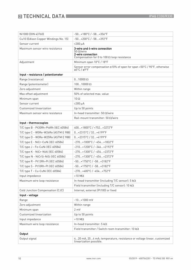
Ni1000 (DIN 43760) -50...+180°C / -58...+356°F
Cu10 (Edison Copper Windings No. 15) -50...+200°C / -58...+392°F
Sensor current ≤300 μA
Maximum sensor wire resistance 3-wire and 4-wire connection3-wire and 4-wire connection3-wire and 4-wire connection3-wire and 4-wire connection50 Ω/wire2-wire connection2-wire connection2-wire connection2-wire connectionCompensation for 0 to 100 Ω loop resistance
Adjustment Minimum span 10°C / 18°F
Sensor error compensation ±10% of span for span <50°C / 90°F, otherwise ±5°C / ±9°F
Input - resistance / potentiometerInput - resistance / potentiometerInput - resistance / potentiometerInput - resistance / potentiometer
Range (resistance) 0...10000 Ω
Range (potentiometer) 100...10000 Ω
Zero adjustment Within range
Max offset adjustment 50% of selected max. value
Minimum span 10 Ω
Sensor current ≤300 μA
Customized linearization Up to 50 points
Maximum sensor wire resistance In-head transmitter: 50 Ω/wire
Rail-mount transmitter: 50 Ω/wire
Input - thermocouplesInput - thermocouplesInput - thermocouplesInput - thermocouples
T/C type B - Pt30Rh-Pt6Rh (IEC 60584) 400...+1800°C / +752...+3272°F
T/C type C - W5Re-W26Re (ASTM E 988) 0...+2315°C / 32...+4199°F
T/C type D - W3Re-W25Re (ASTM E 988) 0...+2315°C / 32...+4199°F
T/C type E - NiCr-CuNi (IEC 60584) -270...+1000°C / -454...+1832°F
T/C type J - Fe-CuNi (IEC 60584) -210...+1200°C / -346...+2192°F
T/C type K - NiCr-NiAl (IEC 60584) -270...+1300°C / -454...+2372°F
T/C type N - NiCrSi-NiSi (IEC 60584) -270...+1300°C / -454...+2372°F
T/C type R - Pt13Rh-Pt (IEC 60584) -50...+1750°C / -58...+3182°F
T/C type S - Pt10Rh-Pt (IEC 60584) -50...+1750°C / -58...+3182°F
T/C type T - Cu-CuNi (IEC 60584) -270...+400°C / -454...+752°F
Input impedance >10 MΩ
Maximum wire loop resistance In-head transmitter (including T/C sensor): 5 kΩ
Field transmitter (including T/C sensor): 10 kΩ
Cold Junction Compensation (CJC) Internal, external (Pt100) or fixed
Input - voltageInput - voltageInput - voltageInput - voltage
Range -10...+1000 mV
Zero adjustment Within range
Minimum span 2 mV
Customized linearization Up to 50 points
Input impedance >10 MΩ
Maximum wire loop resistance In-head transmitter: 5 kΩ
Field transmitter / Switch room transmitter: 10 kΩ
OutputOutputOutputOutput
Output signal 4...20 mA, 20...4 mA; temperature, resistance or voltage linear, customized linearization possible.

TECHNICAL DATA 2
11
IPAQ C330/R330
www.inor.com03/2019 - 4007542201 - TD IPAQ 330 R01 en
Permissible load (Supply voltage-8,0)/0.022
NAMUR compliance Output limits and failure currents according to NAMUR NE 43
Adjustable filtering level 0.17...90 s, (default 1.4s) (3-wire RTD)
Monitoring Sensor break and short circuit monitoring, selectable, upscale ≥21.0 mA or downscale ≤3.6 mA action, individually configurable.
ConfigurationConfigurationConfigurationConfiguration
ConSoft The PC configuration software, ConSoft, is a versatile and user-friendly tool for transmitter configuration.
ConSoft is compatible with Windows XP/Vista/7/8/8.1/10
ConSoft is part of the complete configuration kit, which also contains a USB interface and necessary cables.Full functionality of the transmitter is achieved with ConSoft program version 3.4.0 or later and the firmware in the USB Interface must have a version number 1.2.07 or later.
INOR Connect The app INOR Connect for portable devices (smartphones) is a versatile and user-friendly tool for wireless configuration through Bluetooth® or NFC® technology.Communication via Bluetooth® requires the Bluetooth® interface -ICON-BT, which can be ordered from the manufacturer.
Approvals and certificationsCE The device fulfils the statutory requirements of the EU directives.
The manufacturer certifies that these requirements have been met by applying the CE marking.
Ex approvalsEx approvalsEx approvalsEx approvals
Standard version Without
Intrinsically safe (IS) version Refer to Ex approvalsEx approvalsEx approvalsEx approvals in the separate table below.
Other standards and approvalsOther standards and approvalsOther standards and approvalsOther standards and approvals
Electromagnetic compatibility Directive: 2014/30/EU
Harmonized standards: EN 61326-1 and EN 61326-2-3
NAMUR NE 21
EN 61326-1 and -2-3: Criteria ANE 21: <0.5% of span
RoHS Directive: 2011/65/EUHarmonized standard: EN 50581
Vibration resistance According to IEC 60068-2-6, test Fc, 10...2000 Hz,10 g for in-head mounted / 5 g for rail mounted transmitter
Radio Equipment Directive This product contains NFC communication and conforms to the requirements of the Radio Equipment Directive (RED) 2014/53/EU
1 NFC applies only to later versions of IPAQ 330

2 TECHNICAL DATA
12
IPAQ C330/R330
www.inor.com 03/2019 - 4007542201 - TD IPAQ 330 R01 en
Ex approvals
C330X (intrinsically safe), part no. 70C330X010C330X (intrinsically safe), part no. 70C330X010C330X (intrinsically safe), part no. 70C330X010C330X (intrinsically safe), part no. 70C330X010
ATEX KIWA 16ATEX0038 X II 1 G Ex ia IIC T6...T4 Ga
IECEx IECEx KIWA 16.0016X Ex ia IIC T6...T4 Ga
USA FM17US0283X Cl I Div 1 GP A-D, T4...T6 Cl I Zn 0 AEx/Ex ia IIC T4...T6 Ga
Canada FM17CA0144X
C330X (intrinsically safe), part no. 70C330X012 C330X (intrinsically safe), part no. 70C330X012 C330X (intrinsically safe), part no. 70C330X012 C330X (intrinsically safe), part no. 70C330X012
ATEX KIWA 16ATEX0038 X II 1 G Ex ia IIC T6...T4 Ga
IECEx IECEx KIWA 16.0016X Ex ia IIC T6...T4 Ga
R330X (intrinsically safe), part no. 70R330X010R330X (intrinsically safe), part no. 70R330X010R330X (intrinsically safe), part no. 70R330X010R330X (intrinsically safe), part no. 70R330X010
ATEX KIWA 16ATEX0040 X II 1 G Ex ia IIC T6...T4 Ga
IECEx IECEx KIWA 16.0018X Ex ia IIC T6...T4 Ga
USA FM17US0283X Cl I Div 1 GP A-D, T4...T6 Cl I Zn 0 AEx/Ex ia IIC T4...T6 Ga
Canada FM17CA0144X
R330X (intrinsically safe), part no. 70R330X012R330X (intrinsically safe), part no. 70R330X012R330X (intrinsically safe), part no. 70R330X012R330X (intrinsically safe), part no. 70R330X012
ATEX KIWA 16ATEX0040 X II 1 G Ex ia IIC T6...T4 Ga
IECEx IECEx KIWA 16.0018X Ex ia IIC T6...T4 Ga
TECHNICAL DATA 2
13
IPAQ C330/R330
www.inor.com03/2019 - 4007542201 - TD IPAQ 330 R01 en
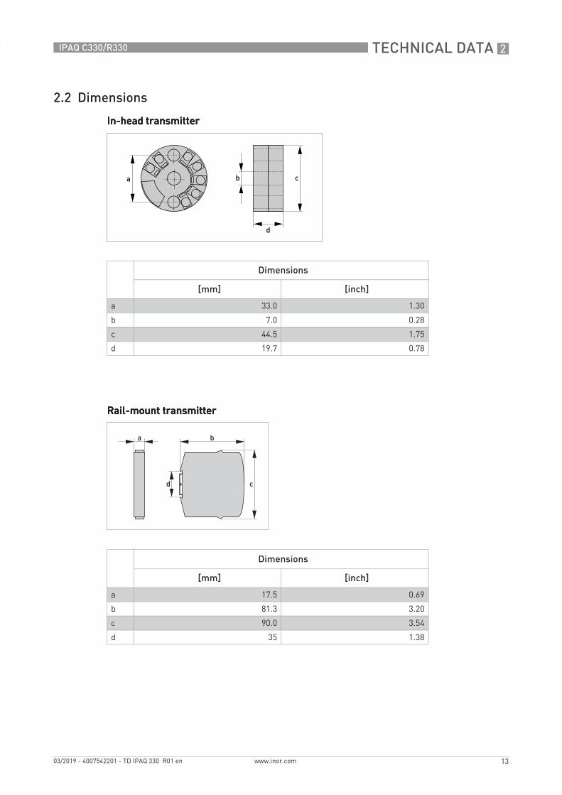
2.2 Dimensions
In-head transmitterIn-head transmitterIn-head transmitterIn-head transmitter
Rail-mount transmitterRail-mount transmitterRail-mount transmitterRail-mount transmitter
Dimensions
[mm] [inch]
a 33.0 1.30
b 7.0 0.28
c 44.5 1.75
d 19.7 0.78
Dimensions
[mm] [inch]
a 17.5 0.69
b 81.3 3.20
c 90.0 3.54
d 35 1.38

2 TECHNICAL DATA
14
IPAQ C330/R330
www.inor.com 03/2019 - 4007542201 - TD IPAQ 330 R01 en
2.3 Temperature data for areas with potentially explosive atmospheres
In-head transmitterIn-head transmitterIn-head transmitterIn-head transmitterIntrinsically safe transmitter
Rail-mount transmitterRail-mount transmitterRail-mount transmitterRail-mount transmitterIntrinsically safe transmitter
Temperature class Ambient temperature Ta
T6 -40°C ≤ Ta ≤ +60°C / -40°F ≤ Ta ≤ +140°F
T5 -40°C ≤ Ta ≤ +75°C / -40°F ≤ Ta ≤ +167°F
T4 -40°C ≤ Ta ≤ +85°C / -40°F ≤ Ta ≤ +185°F
Temperature class Ambient temperature Ta
T6 -40°C ≤ Ta ≤ +60°C / -40°F ≤ Ta ≤ +140°F
T5 -40°C ≤ Ta ≤ +75°C / -40°F ≤ Ta ≤ +167°F
T4 -40°C ≤ Ta ≤ +85°C / -40°F ≤ Ta ≤ +185°F

TECHNICAL DATA 2
15
IPAQ C330/R330
www.inor.com03/2019 - 4007542201 - TD IPAQ 330 R01 en
2.4 Output load diagram
Formula for the maximum permissible output load:permissible RLoad [Ω] = (U-8.0)/0.022
Formula for the maximum permissible output load:permissible RLoad [Ω] = (U-8.0)/0.022
Standard transmitter
Figure 2-1: Output load diagram
X: Power supply U [VDC]Y: Total output load R [Ω]
Intrinsically safe transmitter
Figure 2-2: Output load diagram
X: Power supply U [VDC]Y: Total output load R [Ω]
8
8

2 TECHNICAL DATA
16
IPAQ C330/R330
www.inor.com 03/2019 - 4007542201 - TD IPAQ 330 R01 en
2.5 Electrical data for outputs and inputs
In-head transmitterIn-head transmitterIn-head transmitterIn-head transmitterIntrinsically safe transmitter, C330X - Part number 70C330X010
Intrinsically safe transmitter, C330X - Part number 70C330X012
Rail-mount transmitterRail-mount transmitterRail-mount transmitterRail-mount transmitterIntrinsically safe transmitter, R330X - Part number 70R330X010
Intrinsically safe transmitter, R330X - Part number 70R330X012
Output terminals 6, 7 Input terminals 1, 2, 3, 4
Ui = Vmax ≤ 30 VDC U0 = U0C ≤ 30 VDC
Ii = Imax ≤ 100 mA I0 = ISC ≤ 54 mA
Pi = Pmax ≤ 900 mW P0 ≤ 405 mW
Li 20 μH L0 11 mH
Ci 23.1 nF C0 38.1 nF
Output terminals 6, 7 Input terminals 1, 2, 3, 4
Ui = Vmax ≤ 30 VDC Uo = U0C ≤ 6.5 VDC
Ii = Imax ≤ 100 mA Io = ISC ≤ 11.7 mA
Pi = Pmax ≤ 900 mW Po ≤ 19.1 mW
Li 20 μH Lo 400 mH
Ci 23.1 nF Co 24 μF
Output terminals 21, 22 Input terminals 1, 2, 3, 4
Ui = Vmax ≤ 30 VDC U0 = U0C ≤ 30 VDC
Ii = Imax ≤ 100 mA I0 = ISC ≤ 54 mA
Pi = Pmax ≤ 900 mW P0 ≤ 405 mW
Li 20 μH L0 11 mH
Ci 23.1 nF C0 38.1 nF
Output terminals 21, 22 Input terminals 1, 2, 3, 4
Ui = Vmax ≤ 30 VDC Uo = U0C ≤ 6.5 VDC
Ii = Imax ≤ 100 mA Io = ISC ≤ 11.7 mA
Pi = Pmax ≤ 900 mW Po ≤ 19.1 mW
Li 20 μH Lo 400 mH
Ci 23.1 nF Co 24 μF

TECHNICAL DATA 2
17
IPAQ C330/R330
www.inor.com03/2019 - 4007542201 - TD IPAQ 330 R01 en
2.6 RTD and T/C accuracy table
Typical accuracy ±0.08% of span, max. of ±0.1 K or ±0.1% of span.
Conformance level 95% (2σ)
CJC = Cold Junction Compensation
Accuracies in °C
Input type Temp. range Min. span Accuracy (maximum of) Temp. influence(Dev. from ref. temp. 20°C)
[°C] [°C] [°C]
RTD Pt100 -200...+850 10 ±0.08°C or ±0.08% of span ±0.01% of span per °C
RTD PtX 1 Corresp. to max. 4 kΩ
10 ±0.1°C or ±0.1% of span ±0.01% of span per °C
RTD Ni100 -60...+250 10 ±0.1°C or ±0.1% of span ±0.01% of span per °C
RTD Ni120 -60...+250 10 ±0.1°C or ±0.1% of span ±0.01% of span per °C
RTD Ni1000 -50...+180 10 ±0.1°C or ±0.1% of span ±0.01% of span per °C
RTD Cu10 -50...+200 83 ±1.5°C or ±0.2% of span ±0.02% of span per °C
T/C type B +400...+1800 700 ±1.0°C or ±0.2% of span 2 ±0.01% of span per °C
T/C type C 0...+2315 200 ±1.0°C or ±0.2% of span 2 ±0.01% of span per °C
T/C type D 0...+2315 200 ±1.0°C or ±0.2% of span 2 ±0.01% of span per °C
T/C type E -270...+1000 50 ±0.5°C or ±0.1% of span 2 ±0.01% of span per °C
T/C type J -210...+1200 50 ±0.5°C or ±0.1% of span 2 ±0.01% of span per °C
T/C type K -270...+1300 50 ±0.5°C or ±0.1% of span 2 ±0.01% of span per °C
T/C type N -100...+1300 100 ±0.5°C or ±0.1% of span 2 ±0.01% of span per °C
T/C type N -270...-100 100 ±1.0°C 2 ±0.1% of span per °C
T/C type R -50...+1750 300 ±1.0°C or ±0.1% of span 2 ±0.01% of span per °C
T/C type S -50...+1750 300 ±1.0°C or ±0.1% of span 2 ±0.01% of span per °C
T/C type T -270...+400 50 ±0.25°C or ±0.2% of span 2 ±0.01% of span per °C1 (10 ≤ X ≤ 1000)2 CJC error not included. ≤ 0.5°C within ambient temperature range

2 TECHNICAL DATA
18
IPAQ C330/R330
www.inor.com 03/2019 - 4007542201 - TD IPAQ 330 R01 en
Accuracies in °F
Input type Temp. range Min. span Accuracy (maximum of) Temp. influence(Dev. from ref. temp. 68°F)
[°F] [°F] [°F]
RTD Pt100 -328...+1562 18 ±0.18°F or ±0.1% of span ±0.006% of span per °F
RTD PtX 1 Corresp. to max. 4 kΩ
18 ±0.18°F or ±0.1% of span ±0.006% of span per °F
RTD Ni100 -76...+482 18 ±0.18°F or ±0.1% of span ±0.006% of span per °F
RTD Ni120 -76...+482 18 ±0.18°F or ±0.1% of span ±0.006% of span per °F
RTD Ni1000 -58...+356 18 ±0.18°F or ±0.1% of span ±0.006% of span per °F
RTD Cu10 -58...+392 149 ±2.7°F or ±0.2% of span ±0.006% of span per °F
T/C type B +752...+3272 1260 ±1.8°F or ±0.1% of span 2 ±0.006% of span per °F
T/C type C +32...+4199 360 ±1.8°F or ±0.1% of span 2 ±0.006% of span per °F
T/C type D +32...+4199 360 ±1.8°F or ±0.1% of span 2 ±0.006% of span per °F
T/C type E -454...+1832 90 ±0.9°F or ±0.1% of span 2 ±0.006% of span per °F
T/C type J -346...+2192 90 ±0.9°F or ±0.1% of span 2 ±0.006% of span per °F
T/C type K -454...+2372 90 ±0.9°F or ±0.1% of span 2 ±0.006% of span per °F
T/C type N -148...+2372 180 ±0.9°F or ±0.1% of span 2 ±0.006% of span per °F
T/C type N -454...-148 180 ±1.8°F 2 ±0.18% of span per °F
T/C type R -58...+3182 540 ±1.8°F or ±0.1% of span 2 ±0.006% of span per °F
T/C type S -58...+3182 540 ±1.8°F or ±0.1% of span 2 ±0.006% of span per °F
T/C type T -454...+752 90 ±0.9°F or ±0.1% of span 2 ±0.006% of span per °F1 (10 ≤ X ≤ 1000)2 CJC error not included. ≤ 0.9°F within ambient temperature range

INSTALLATION 3
19
IPAQ C330/R330
www.inor.com03/2019 - 4007542201 - TD IPAQ 330 R01 en
3.1 Intended use
The IPAQ 330 signal conditioner is a universal two-wire transmitter intended to be used in industrial environments and designed for measurements of:
• Temperature measurements with resistance thermometers• Temperature measurements with thermocouples• Voltage measurements in a range up to 1000 mV• Resistance measurement up to 10 kΩ• Measurements with potentiometers
C330 / C330X is intended for installation in a DIN B-head or larger according to EN 50446.R330 / R330X is intended for installation on a 35 mm DIN-rail according to EN 60715/DIN 50022.
The transmitters are configured from a PC by using the ConSoft program and a transmitter configuration kit (USB connection), or by a smartphone with built-in NFC support
3.2 In-head transmitter
The transmitter is intended for installation in DIN B connection head or larger. For detailed information refer to Dimensions on page 13.
You may only use transmitters labelled with the "Ex" symbol in potentially explosive areas or connect them to a sensor located in those areas. Additionally always note the zone(s) for which the devices have an approval. Otherwise the transmitters might cause an explosion that can result in fatal injuries.
Responsibility for the correct use of the devices with special regard to suitability, intended use and the field of application lies solely with the operator. To avoid any kind of incorrect use, also note the information in the chapter "Device description".
The transmitters do not contain any serviceable parts inside. Any substitution of components may impair the intrinsic safety of the versions with an Ex approval. Always send defective devices to the manufacturer or the local distributor for repair or exchange. If this is the case, attach a clear description of the malfunction for warranty claims.
The manufacturer is not liable for any damage resulting from improper use or use for other than the intended purpose. To avoid any kind of incorrect use, also note the information in the chapter "Device description".
Responsibility for the use of the measuring devices with regard to suitability, intended use and corrosion resistance of the used materials against the measured fluid lies solely with the operator.
This device is a Group 1, Class A device as specified within CISPR11:2009. It is intended for use in industrial environment. There may be potential difficulties in ensuring electromagnetic compatibility in other environments, due to conducted as well as radiated disturbances.
IPAQ C330X must be installed in an enclosure having an Ingress Protection suitable for the actual use but at least IP20.

3 INSTALLATION
20
IPAQ C330/R330
www.inor.com 03/2019 - 4007542201 - TD IPAQ 330 R01 en
Figure 3-1: Connection head installation kit
1 M4 screw2 Spring3 Lock washer4 Wires from the measuring insert.5 MI cable
The connection head installation kit does not belong to the standard scope of delivery of the transmitter, you have to order it separately.
The transmitter is optionally available in an intrinsically safe version (zone 0, 1 and 2) for installation in potentially explosive atmospheres. The intrinsically safe version must be supplied by an intrinsically safe power supply unit or Zener barrier placed outside of the potentially explosive zone.
The transmitter has been developed for an operating temperature of -40...+85°C / -40...+185°F. To avoid destruction or damage of the device, always assure that the operating temperature or ambient temperature does not exceed the permissible range. The thermowell also transfer the process temperature to the transmitter housing. If the process temperature is close to or exceeds the maximum temperature of the transmitter, then the temperature in the transmitter housing can rise above the maximum permissible temperature. One way to decrease the head transfer via thermowell is to install the transmitter further away from the heat source. Inversely similar measurements can be done if the temperature gets below specified minimum temperature.

INSTALLATION 3
21
IPAQ C330/R330
www.inor.com03/2019 - 4007542201 - TD IPAQ 330 R01 en
3.3 Rail-mount transmitter
These transmitters are intended for installation on a 35 mm rail according to EN 60715 / DIN 50022.
1 Fix the upper part of the transmitter onto the rail.2 Press the lower part of the transmitter against the rail.3 To remove the transmitter, bend the locking device using a small screwdriver. Carefully pull
the transmitter in the forward direction.
IPAQ R330X must be installed in an enclosure having an ingress protection suitable for the actual use but at least IP20.
Figure 3-2: Rail installation
The manufacturer has developed the R330 for an operating temperature range of-40...+85°C / -40...+185°F.To avoid destruction or damage of the device, always note the following items: • Assure that the operating temperature or the ambient temperature does not exceed the
permissible range.

4 ELECTRICAL CONNECTIONS
22
IPAQ C330/R330
www.inor.com 03/2019 - 4007542201 - TD IPAQ 330 R01 en
4.1 Notes on installation
4.2 Electrical connections of in-head transmitter
The input and output signals and the power supply must be connected in accordance with the following illustrations. The transmitter is easy to install with the connection head installation kit. To avoid measuring errors, all cables must be connected properly and the screws tightened correctly.
RTD and potentiometer measurementRTD and potentiometer measurementRTD and potentiometer measurementRTD and potentiometer measurement
Inspect the packaging carefully for damages or signs of rough handling. Report damage to the carrier and to the local office of the manufacturer.
Do a check of the packing list to make sure that you have all the elements given in the order.
Look at the device nameplate to ensure that the device is delivered according to your order.
Pt100Pt100Pt100Pt100…Pt1000, Ni100, Ni120, Cu10Pt1000, Ni100, Ni120, Cu10Pt1000, Ni100, Ni120, Cu10Pt1000, Ni100, Ni120, Cu102-wire connection2-wire connection2-wire connection2-wire connection
Pt100Pt100Pt100Pt100…Pt1000, Ni100, Ni120, Cu10Pt1000, Ni100, Ni120, Cu10Pt1000, Ni100, Ni120, Cu10Pt1000, Ni100, Ni120, Cu103-wire connection3-wire connection3-wire connection3-wire connection
Pt100Pt100Pt100Pt100…Pt1000, Ni100, Ni120, Cu10Pt1000, Ni100, Ni120, Cu10Pt1000, Ni100, Ni120, Cu10Pt1000, Ni100, Ni120, Cu104-wire connection4-wire connection4-wire connection4-wire connection
Resistance, 2-wire connectionResistance, 2-wire connectionResistance, 2-wire connectionResistance, 2-wire connection Resistance, 3-wire connectionResistance, 3-wire connectionResistance, 3-wire connectionResistance, 3-wire connection Resistance, 4-wire connectionResistance, 4-wire connectionResistance, 4-wire connectionResistance, 4-wire connection
Potentiometer, 3-wire slide wirePotentiometer, 3-wire slide wirePotentiometer, 3-wire slide wirePotentiometer, 3-wire slide wire

ELECTRICAL CONNECTIONS 4
23
IPAQ C330/R330
www.inor.com03/2019 - 4007542201 - TD IPAQ 330 R01 en
Thermocouple and voltage measurementThermocouple and voltage measurementThermocouple and voltage measurementThermocouple and voltage measurement
4.3 Connection diagram of in-head transmitter
ThermocoupleThermocoupleThermocoupleThermocouple VoltageVoltageVoltageVoltage Thermocouple with external CJC Thermocouple with external CJC Thermocouple with external CJC Thermocouple with external CJC (Pt100)(Pt100)(Pt100)(Pt100)
Always establish the electrical connections according to the following diagrams. Otherwise it can come to destruction or damage of the transmitter. Note that the maximum output load always depends on the power supply. If the maximum output load is exceeded, then the measured value will become incorrect. For further information refer to Technical data on page 8.
Figure 4-1: Connection diagram
1 Voltage supply 8.0…36 VDC (terminals 6, 7)2 RLoad3 Input4 Output5 Thermocouple6 Pt100 3-wire connection

4 ELECTRICAL CONNECTIONS
24
IPAQ C330/R330
www.inor.com 03/2019 - 4007542201 - TD IPAQ 330 R01 en
4.4 Connection diagram of in-head transmitter (intrinsically safe)
Figure 4-2: Connection diagram
1 Input2 Potentially explosive area3 Safe area4 RLoad5 Voltage supply 8.0…30 VDC (intrinsically safe)6 Output signal (4...20mA)
+-
The transmitter may be operated in areas with potentially explosive atmospheres if the voltage supply is ensured by means of an associated apparatus.

ELECTRICAL CONNECTIONS 4
25
IPAQ C330/R330
www.inor.com03/2019 - 4007542201 - TD IPAQ 330 R01 en
4.5 Electrical connections of rail-mount transmitter
The input and output signals and the power supply must be connected in accordance with the following illustrations. To avoid measuring errors, all cables must be connected properly and the screws tightened correctly.
RTD and potentiometer measurementRTD and potentiometer measurementRTD and potentiometer measurementRTD and potentiometer measurement
Thermocouple and voltage measurementThermocouple and voltage measurementThermocouple and voltage measurementThermocouple and voltage measurement
Pt100Pt100Pt100Pt100…Pt1000, Ni100, Ni120, Cu10Pt1000, Ni100, Ni120, Cu10Pt1000, Ni100, Ni120, Cu10Pt1000, Ni100, Ni120, Cu102-wire connection2-wire connection2-wire connection2-wire connection
Pt100Pt100Pt100Pt100…Pt1000, Ni100, Ni120, Cu10Pt1000, Ni100, Ni120, Cu10Pt1000, Ni100, Ni120, Cu10Pt1000, Ni100, Ni120, Cu103-wire connection3-wire connection3-wire connection3-wire connection
Pt100Pt100Pt100Pt100…Pt1000, Ni100, Ni120, Cu10Pt1000, Ni100, Ni120, Cu10Pt1000, Ni100, Ni120, Cu10Pt1000, Ni100, Ni120, Cu104-wire connection4-wire connection4-wire connection4-wire connection
Resistance, 2-wire connectionResistance, 2-wire connectionResistance, 2-wire connectionResistance, 2-wire connection Resistance, 3-wire connectionResistance, 3-wire connectionResistance, 3-wire connectionResistance, 3-wire connection Resistance, 4-wire connectionResistance, 4-wire connectionResistance, 4-wire connectionResistance, 4-wire connection
Potentiometer, 3-wire slide wirePotentiometer, 3-wire slide wirePotentiometer, 3-wire slide wirePotentiometer, 3-wire slide wire
ThermocoupleThermocoupleThermocoupleThermocouple VoltageVoltageVoltageVoltage Thermocouple with external CJC Thermocouple with external CJC Thermocouple with external CJC Thermocouple with external CJC (Pt100)(Pt100)(Pt100)(Pt100)

4 ELECTRICAL CONNECTIONS
26
IPAQ C330/R330
www.inor.com 03/2019 - 4007542201 - TD IPAQ 330 R01 en
4.6 Connection diagram of rail-mount transmitter
4.7 Connection diagram of rail-mount transmitter (intrinsically safe)
Figure 4-3: Connection diagram
1 Input2 RLoad3 Voltage supply 8...36 VDC and output 4...20 mA
Figure 4-4: Connection diagram
1 Input (intrinsically safe)2 Classified hazardous area (potentially explosive area e.g. zone 0, 1 or 2)3 Safe area4 RLoad (intrinsically safe)5 Voltage supply 8,0…30 VDC (intrinsically safe - terminals 21, 22)

ORDER INFORMATION 5
27
IPAQ C330/R330
www.krohne.com03/2019 - 4007542201 - TD IPAQ 330 R01 en
5.1 Order code
The characters of the order code highlighted in light grey describe the standard.
VTT1VTT1VTT1VTT1 4444 DesignDesignDesignDesign
1 Head mounting (type C)
2 DIN-rail mounting, 35 mm / 1.38" (type R)
TypeTypeTypeType
C IPAQ 330, digital, standard, 4...20 mA
ApprovalsApprovalsApprovalsApprovals
0 Without
1 ATEX: II 1G Ex ia 11C T4-T6
2 IECEx: Ex ia IIC T6...T4 Ga
A FM US: Cl I Div 1 GP A-D, T4...T6
E FM CA: Cl I Zn 0 AEx/Ex ia IIC T4...T6 Ga
SensorSensorSensorSensor
0 Without
1 Pt 10
2 Pt 50
3 Pt100 (α = 0.00385)
4 Pt100 (α = 0.003902)
5 Pt100 (α = 0.003916)
8 Pt1000 (α = 0.00385)
A Potentiometer
B Thermocouple type B
C Thermocouple type C
E Thermocouple type E
H Thermocouple type J
K Thermocouple type K
L Thermocouple type L
N Thermocouple type N
R Thermocouple type R
S Thermocouple type S
T Thermocouple type T
U Cu 10
V Ni 50
W Ni 100
X Ni 120
Y Ni 1000
Z Customized
VTT1VTT1VTT1VTT1 4444 Continued on next pageContinued on next pageContinued on next pageContinued on next page

5 ORDER INFORMATION
28
IPAQ C330/R330
www.inor.com 03/2019 - 4007542201 - TD IPAQ 330 R01 en
WiringWiringWiringWiring
0 Without
2 2-wire (1 x sensor)
3 3-wire (1 x sensor)
4 4-wire (1 x sensor)
Measuring rangeMeasuring rangeMeasuring rangeMeasuring range
0 Without
1 -50...+50°C / -58...+122°F
2 -50...+100°C / -58...+212°F
3 -50...+150°C / -58...+302°F
4 0...+50°C / +32...+122°F
5 0...+100°C / +32...+212°F
6 0...+150°C / +32...+302°F
7 0...+200°C / +32...+392°F
8 0...+250°C / +32...+482°F
A 0...+300°C / +32...+572°F
B 0...+350°C / +32...+662°F
C 0...+400°C / +32...+752°F
D 0...+450°C / +32...+842°F
E 0...+500°C / +32...+932°F
F 0...+600°C / +32...+1112°F
G 0...+800°C / +32...+1472°F
H 0...+1000°C / +32...+1832°F
K 0...+1200°C / +32...+2192°F
Z Customized
CertificatesCertificatesCertificatesCertificates
0 Without
Accessories / phys. characteristicsAccessories / phys. characteristicsAccessories / phys. characteristicsAccessories / phys. characteristics
0 Without
1 Head-mounted transmitter assembled to DIN-rail clip, 35mm
2 Assembly kit for in-head mounting (spring-load)
F Transmitter mounted into a plastic-housing 82x80x55mm, 2x M16x1,5 / IP65
VTT1VTT1VTT1VTT1 4444 Continued on next pageContinued on next pageContinued on next pageContinued on next page

ORDER INFORMATION 5
29
IPAQ C330/R330
www.inor.com03/2019 - 4007542201 - TD IPAQ 330 R01 en
Calibration certificateCalibration certificateCalibration certificateCalibration certificate
0 Without
2 2 points (0 and 100%)
3 3 points (0, 50 and 100%)
4 5 points (0, 25, 50, 75 and 100%)
5 11 points (0, 10, ..., 100%)
Z Customized
ManualsManualsManualsManuals
0 Without
1 German
3 English
4 French
5 Spanish
G German / English
Private labelPrivate labelPrivate labelPrivate label
0 KROHNE Standard Version
VTT1VTT1VTT1VTT1 4444 Complete order codeComplete order codeComplete order codeComplete order code

6 NOTES
30
IPAQ C330/R330
www.inor.com 03/2019 - 4007542201 - TD IPAQ 330 R01 en

NOTES 6
31
IPAQ C330/R330
www.inor.com03/2019 - 4007542201 - TD IPAQ 330 R01 en

Inor North America7 Dearborn RoadPeabody, MA 01960United StatesPhone: +1 978 826 6900Fax: +1 978 535 1720E-mail: [email protected]: www.inor.com
Inor Transmitter GmbHAm See 24D-47279 DuisburgGermanyPhone: +49-(0)203 7382 762 0Fax: +49-(0)203 7382 762 2E-mail: [email protected]: www.inor-gmbh.de
The current list of all INOR contacts and addresses can be found at: www.inor.com
Inor Process ABPO Box 9125SE-200 39 MalmöSwedenPhone: +46-(0)40-312 560 Fax: +46-(0)40-312 570 E-mail: [email protected]
Subsidiaries
Inor Transmitter Oy Unikkotie 13FI-01300 VantaaFinlandPhone: +358-(0)10-4217900 Fax: +358-(0)10-4217901 E-mail: [email protected]: www.krohne-inor.fi
© IN
OR
03/
2019
- 4
0075
4220
1 -
TD IP
AQ
330
R01
en