Embed Size (px)
Citation preview
TCX2-23343-BAC
OVERVIEW
Doc: 70-00-0623, V1.3R0, 20170131 © Vector Controls GmbH, Switzerland Page 1 Subject to alteration www.vectorcontrols.com
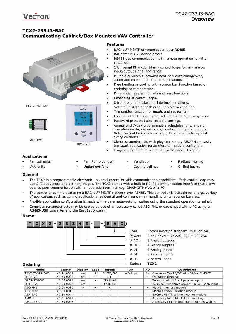
TCX2-23343-BAC Communicating Cabinet/Box Mounted VAV Controller
Features
BACnet™ MS/TP communication over RS485
BACnet™ B-ASC device profile
RS485 bus communication with remote operation terminal
OPA2-VC.
2 Universal PI and/or binary control loops for any analog input/output signal and range.
Multiple auxiliary functions: heat-cool auto changeover, automatic enable, set point compensation.
Free heating or cooling with economizer function based on
enthalpy or temperature.
Differential, averaging, min and max functions
Cascading of control loops.
8 free assignable alarm or interlock conditions,
Selectable state of each output on alarm condition.
Transmitter function for inputs and set points.
Functions for dehumidifying, set point shift and many more.
Password protected and lockable settings.
Annual and 7-day programmable schedules for change of operation mode, setpoints and position of manual outputs. Note: no real time clock included. Time need to be synced every 24 hours.
Clone parameter sets with plug-in memory AEC-PM1 – easily transport application parameters to multiple controllers.
Program and monitor using free pc software: EasySet!
Applications
Fan coil units
VAV units
Fan, Pump control
Underfloor fans
Ventilation
Cooling ceilings
Radiant heating
Chilled beams
General
The TCX2 is a programmable electronic universal controller with communication capabilities. Each control loop may use 2 PI sequences and 6 binary stages. The TCX2 comes with a built in RS485 communication interface that allows peer to peer communication with an operation terminal e.g. OPA2-(2TH)-VC or a PC.
The controller communicates on a BACnet™ MS/TP network over RS485. This controller is suitable for a large variety of applications such as zoning applications residential and commercial, air handling units, economizers etc.
Flexible application configuration is made with a parameter-setting routine using the standard operation terminal.
Complete parameter sets may be copied by use of an accessory called AEC-PM1 or exchanged with a PC using an RS485-USB converter and the EasySet program.
Name
Ordering
Model Item# Display Loop Inputs DO AO Description
TCX2-23343-BAC 40-11 0097 no 2 3 NTC, 3V 4 Relays 3V Controller 24VAC/DC with BACnet® MS/TP
OPA2-VC 40-50 0007 Yes - 1T - - Operation terminal
OPA2-2TH-VC 40-50 0023 Yes - 1T+1H+2 Terminal with HT + 2 passive inputs
OPT-2-VC 40-50 0098 Yes 1NTC 1V Terminal with touch screen, 1NTC+1VDC input
AEC-PM1 40-50 0016 - - - - - Plug-In memory module
AEX-MOD 40-50 0013 - - - - - Modbus communication module
AEX-BAC 40-50 0044 - - - - - BACnet MS/TP communication module
AMM-1 40-51 0022 - - - - - Accessory for cabinet door mounting
AEC-USB-01 40-50 0046 - - - - - Accessory to exchange parameter set with PC
OPA2-VC
AEC-PM1
TCX2-23343-BAC
Com: Communication standard, MOD or BAC
Power: Blank or 24 = 24VAC, 230 = 230VAC
# AO: 3 Analog outputs
# DO: 4 Binary outputs
# UI: 3 Analog inputs
# DI: 3 Passive inputs
# LP: 2 control loops
Series: TCX2
T C X 2 - 2 3 3 4 3 - B ( ) - C A
TCX2-23343-BAC
TECHNICAL DATA
Doc: 70-00-0623, V1.3R0, 20170131 © Vector Controls GmbH, Switzerland Page 2
Subject to alteration www.vectorcontrols.com
Technical specifications
Important notice and safety advice
This device is for use as operating controls. It is not a safety device! Where a device failure endangers human life and/or property, it is the responsibility of the client, installer and system designer to add additional safety devices to prevent a system failure caused by such a device failure. Ignoring specifications and local regulations may cause equipment damage and endangers life and property. Tampering with the device and misapplication will void warranty.
Power supply Power requirements 24 VAC ±10%, 50/60 Hz, SELV to HD 384, Class II, 48VA max
Power consumption Max. 10 VA
Electrical connection Screw terminal connectors for wire 0.34…2.5 mm2 (AWG 24…12)
Signal inputs Passive input
Type & range:
X1 to X3, Passive Temperature NTC or open contact
NTC (Sxx-Tn10, 10kΩ@20°C): -40…140 °C (-40…284 °F)
Analog input
Input signal
Resolution Impedance
X4 to X6
0...10 V
9.76 mV (10 bit) 98kΩ
Signal outputs Analog outputs Output signal
Resolution
Maximum load
Y1 to Y3 DC 0...10 V
9.76 mV (10 bit)
≥1kΩ
Relays outputs: AC Voltage
DC Voltage
0…250 VAC, full-load current 3A, locked-rotor 18A.
0…30 VDC, full-load current 3A, locked-rotor 18A.
Insulation strength
between relays contacts and system electronics:
between neighboring contacts:
4000V AC to EN 60 730-1
1250V AC to EN 60 730-1
Connection to
remote terminal
Hardware interface
Cabling
RS485 in accordance with EIA/TIA 485
Twisted pair cable category 5 or 6
Network Hardware interface
Max nodes per network
Max nodes per segment
RS485 in accordance with EIA/TIA 485
128
64 (Vector devices only)
Conductors
Impedance
Nominal capacitance
Shielded Twisted Pair (STP) cable
100 - 130 ohm
100 pF/m 16pF/ft. or lower
Galvanic isolation The communication circuitry is isolated
Line termination A line termination resistance (120 ohm) shall be connected between
the terminals (+) and (-) of the furthermost node of the network
Network topology Daisy chain according EIA/TIA 485 specifications
Recommended maximum length per chain 1200 m (4000 ft.)
BACnet™ Communication standard BACnet™ MS/TP Master on RS485
Communication speed 9600, 19200, 38400, 57600, 76800, 115200
BTL listed May 2014
Environment Operation
Climatic conditions
Temperature
Humidity
To IEC 721-3-3
class 3K5
0…50 °C (32…122 °F)
<95 % RH non-condensing
Transport & storage
Climatic conditions
Temperature
Humidity
Mechanical conditions
To IEC 721-3-2 and IEC 721-3-1
class 3K3 and class 1K3
-25…70 °C (-13…158 °F)
<85 % RH non-condensing
class 2M2
Standards conformity
EMC directive
Low voltage directive
2004/108/EC
2006/95/EC
Product standards
Automatic electrical controls for household and
similar use
EN 60 730 –1
Electromagnetic compatibility for
industrial and domestic sector
Emissions: EN 60 730-1
Immunity: EN 60 730-1
Degree of protection IP00 to EN 60 529
Pollution class II (EN 60 730-1)
Safety class: III (IEC 60536) only if SELV is connected to DO, else II
Overvoltage category III (EN 60 730-1)
Product standards:
Temperature- indicating and -
regulating equipment
Mark: c(ETL)us
UL 873
CSA C22.2 No. 24
Certified by Intertek: 4005917
General Material Fire proof ABS plastic (UL94 class V-0)
Dimensions (H x W x D) 57 x 147 x 115 mm (2.3 x 5.8 x 4.5 in)
Weight (including package) 380g (13.4 oz)
TCX2-23343-BAC
TECHNICAL DATA
Doc: 70-00-0623, V1.3R0, 20170131 © Vector Controls GmbH, Switzerland Page 3
Subject to alteration www.vectorcontrols.com
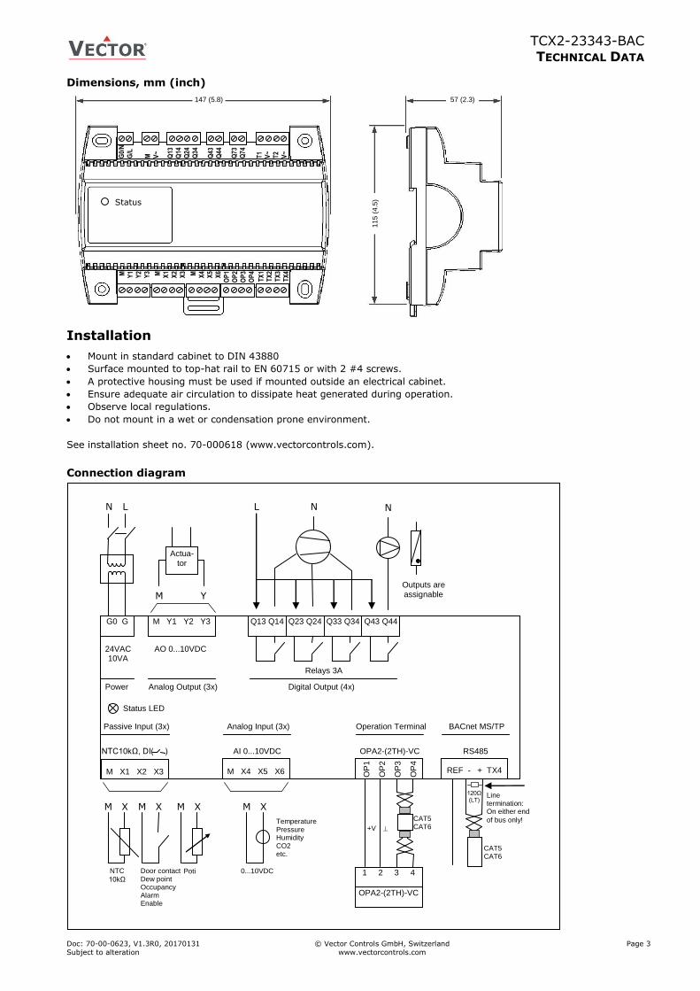
Dimensions, mm (inch)
Installation
Mount in standard cabinet to DIN 43880
Surface mounted to top-hat rail to EN 60715 or with 2 #4 screws.
A protective housing must be used if mounted outside an electrical cabinet.
Ensure adequate air circulation to dissipate heat generated during operation.
Observe local regulations.
Do not mount in a wet or condensation prone environment.
See installation sheet no. 70-000618 (www.vectorcontrols.com).
Connection diagram
G0 G
N L
M Y1 Y2 Y3
M Y
AO 0...10VDC
Actua-tor
Q13 Q14
Analog Output (3x) Power
24VAC 10VA
Q23 Q24
Q33 Q34
Q43 Q44
Digital Output (4x)
Relays 3A
N L N
Outputs are assignable
Status LED
M X1 X2 X3
NTC10kΩ, DI( )
M X4 X5 X6
AI 0...10VDC
Passive Input (3x) Analog Input (3x)
OP
1
OP
2
OP
3
OP
4
OPA2-(2TH)-VC
Operation Terminal
REF - + TX4
RS485
BACnet MS/TP
M X M X
NTC
10kΩ
M X
Poti
M X
0...10VDC
Temperature Pressure Humidity CO2 etc.
Door contact Dew point Occupancy Alarm Enable
1 2 3 4
OPA2-(2TH)-VC
+V
CAT5 CAT6
CAT5 CAT6
120Ω (LT)
Line termination: On either end
of bus only!
147 (5.8) 57 (2.3)
11
5 (
4.5
)
G0/
N
G/L
M
V~
Q13
Q
14
Q24
Q34
Q43
Q44
Q73
Q74
T1
V~
T2
V~
M
Y1
Y2
Y3 M
X1
X2
X3 M
X4
X5
X6
OP
1
OP
2
OP
3
OP
4
TX
1 T
X2
TX
3
TX
4
Status

TCX2-23343-BAC
TECHNICAL DATA
Doc: 70-00-0623, V1.3R0, 20170131 © Vector Controls GmbH, Switzerland Page 4
Subject to alteration www.vectorcontrols.com
TCX2-23343-BAC
TECHNICAL DATA
Doc: 70-00-0623, V1.3R0, 20170131 © Vector Controls GmbH, Switzerland Page 5
Subject to alteration www.vectorcontrols.com
Selection of actuators and sensors
Temperature sensors: For connections on X1 to X3 use Vector Controls NTC sensors to achieve maximum accuracy: SDB-Tn10-20 (duct), SRA-Tn10 (room), SDB-Tn10-20 + AMI-S10 as immersion sensor.
Actuators: Choose modulating actuators with an input signal type of 0/2-10 VDC. 3-point actuators with constant running time are recommended.
Binary auxiliary devices (e.g. pumps, fans, on/off valves, humidifiers, etc.): Do not directly connect devices that exceed specified limits in technical specifications – observe startup current on inductive loads.
Electrical connections
Use only twisted pair copper conductors for input connections. The operating voltage must comply with the requirements for safety extra-low voltage (SELV) as per EN 60 730.
For devices with 24VAC power supply: Use safety insulating transformers with double insulation. They must be designed for 100% ON-time. When using several transformers in one system the connection terminal 1 must be galvanically connected. The TCX2 is designed for operation by AC 24 V, max. 10 Amp, safety extra-low voltage that is short-circuit-proof. Supplying voltages above AC 24 V may damage or destroy the controller or any other connected devices.
Additionally, connections to voltages exceeding 42 V endanger personnel safety. Observe limits mentioned in the technical specifications. Local regulations must be observed at all times.
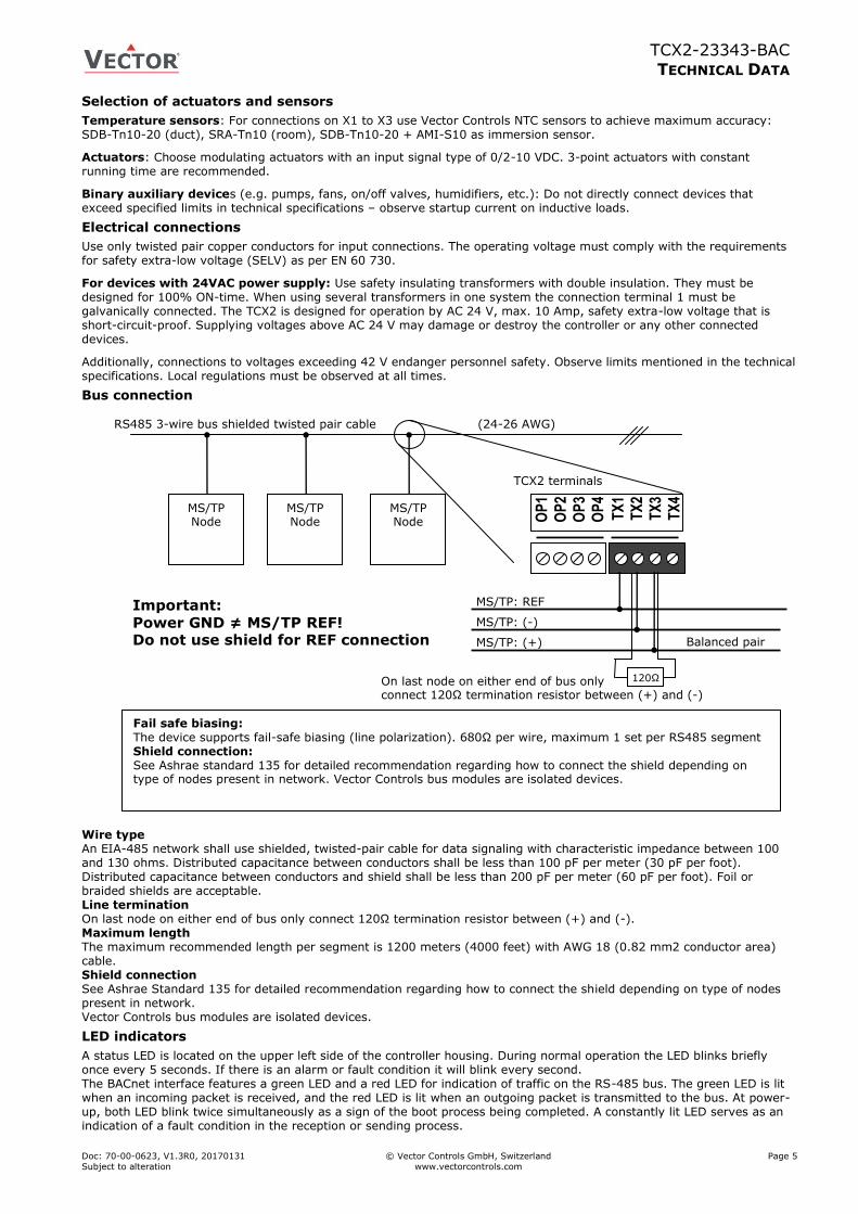
Bus connection
Wire type An EIA-485 network shall use shielded, twisted-pair cable for data signaling with characteristic impedance between 100 and 130 ohms. Distributed capacitance between conductors shall be less than 100 pF per meter (30 pF per foot). Distributed capacitance between conductors and shield shall be less than 200 pF per meter (60 pF per foot). Foil or braided shields are acceptable. Line termination On last node on either end of bus only connect 120Ω termination resistor between (+) and (-). Maximum length The maximum recommended length per segment is 1200 meters (4000 feet) with AWG 18 (0.82 mm2 conductor area) cable. Shield connection See Ashrae Standard 135 for detailed recommendation regarding how to connect the shield depending on type of nodes present in network. Vector Controls bus modules are isolated devices.
LED indicators
A status LED is located on the upper left side of the controller housing. During normal operation the LED blinks briefly once every 5 seconds. If there is an alarm or fault condition it will blink every second. The BACnet interface features a green LED and a red LED for indication of traffic on the RS-485 bus. The green LED is lit when an incoming packet is received, and the red LED is lit when an outgoing packet is transmitted to the bus. At power-up, both LED blink twice simultaneously as a sign of the boot process being completed. A constantly lit LED serves as an indication of a fault condition in the reception or sending process.
RS485 3-wire bus shielded twisted pair cable (24-26 AWG)
On last node on either end of bus only connect 120Ω termination resistor between (+) and (-)
MS/TP Node
MS/TP Node
MS/TP Node O
P1
OP
2
OP
3
OP
4
TX
1
TX
2
TX
3
TX
4
MS/TP: REF
MS/TP: (-)
MS/TP: (+)
Important:
Power GND ≠ MS/TP REF! Do not use shield for REF connection
120Ω
Balanced pair
Fail safe biasing: The device supports fail-safe biasing (line polarization). 680Ω per wire, maximum 1 set per RS485 segment Shield connection: See Ashrae standard 135 for detailed recommendation regarding how to connect the shield depending on type of nodes present in network. Vector Controls bus modules are isolated devices.
TCX2 terminals

TCX2-23343-BAC
TECHNICAL DATA
Doc: 70-00-0623, V1.3R0, 20170131 © Vector Controls GmbH, Switzerland Page 6
Subject to alteration www.vectorcontrols.com
BACnet® specifications
TCX2-BAC Protocol Implementation Conformance Statement (PICS)
Vendor Name: Vector Controls Product Name: TCX2 Controls series TCX2 product description: The TCX2 communicating BACnet® controllers are designed as universal controls equipment suitable for a large number of applications. They may be used in zoning and other applications which are monitored by a BACnet® MS/TP network.
Supported BACnet® Interoperability Blocks (BIBB)
The BACnet® interface conforms to the B-ASC device profile (BACnet® Application Specific Controller). The following BACnet® Interoperability Building Blocks (BIBB) are supported.
BIBB Type Name
DS-RP-B Data sharing Read property - B
DS-RPM-B Data sharing Read property multiple - B
DS-WP-B Data sharing Write property - B
DM-DCC-B Device management Device communication Control - B
DM-DDB-B Device management Dynamic device binding - B
DM-DOB-B Device management Dynamic object binding - B
DM-TS-B Device management Time synchronisation - B
DM-UTC-B Device management UTC Time synchronisation - B
DM-RD-B Device management Reinitialize device - B
Supported standard BACnet® application services
- Read Property - Read Property Multiple - Write Property - Device Communication. Needs a password which is “Vector” (case sensitive and without the quotes). - I-Am - I-Have - Time Synchronisation - UTC Time Synchronisation - Reinitialize Device (“cold” or “warm”). Needs a password which is “Vector” (case sensitive and without the quotes).
Supported standard Object types
- Device - Analog input - Analog value - Binary value - Multi-state value
LED indicators
The BACnet® interface features a green LED and a red LED for indication of traffic on the RS-485 bus. The green LED is lit when an incoming packet is received, and the red LED is lit when an outgoing packet is transmitted to the bus. At power-up, both LED blink twice simultaneously as a sign of the boot process being completed. A constantly lit LED serves as an indication of a fault condition in the reception or sending process.
TCX2-23343-MOD
DISPLAY AND OPERATION
Doc: 70-00-0623, V1.3R0, 20170131 © Vector Controls GmbH, Switzerland Page 7 Subject to alteration www.vectorcontrols.com
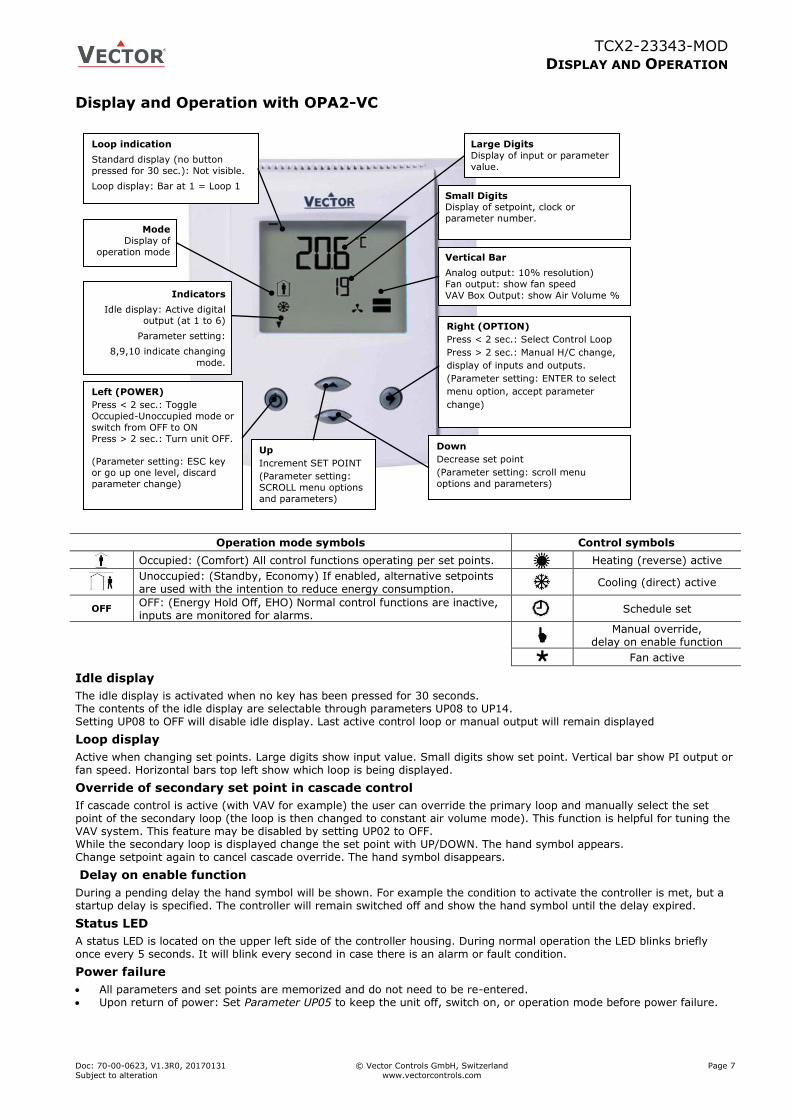
Display and Operation with OPA2-VC
Operation mode symbols Control symbols
Occupied: (Comfort) All control functions operating per set points.
Heating (reverse) active
Unoccupied: (Standby, Economy) If enabled, alternative setpoints are used with the intention to reduce energy consumption.
Cooling (direct) active
OFF OFF: (Energy Hold Off, EHO) Normal control functions are inactive, inputs are monitored for alarms.
Schedule set
Manual override, delay on enable function
Fan active
Idle display
The idle display is activated when no key has been pressed for 30 seconds. The contents of the idle display are selectable through parameters UP08 to UP14. Setting UP08 to OFF will disable idle display. Last active control loop or manual output will remain displayed
Loop display
Active when changing set points. Large digits show input value. Small digits show set point. Vertical bar show PI output or fan speed. Horizontal bars top left show which loop is being displayed.
Override of secondary set point in cascade control
If cascade control is active (with VAV for example) the user can override the primary loop and manually select the set point of the secondary loop (the loop is then changed to constant air volume mode). This function is helpful for tuning the VAV system. This feature may be disabled by setting UP02 to OFF. While the secondary loop is displayed change the set point with UP/DOWN. The hand symbol appears. Change setpoint again to cancel cascade override. The hand symbol disappears.
Delay on enable function
During a pending delay the hand symbol will be shown. For example the condition to activate the controller is met, but a startup delay is specified. The controller will remain switched off and show the hand symbol until the delay expired.
Status LED
A status LED is located on the upper left side of the controller housing. During normal operation the LED blinks briefly once every 5 seconds. It will blink every second in case there is an alarm or fault condition.
Power failure
All parameters and set points are memorized and do not need to be re-entered. Upon return of power: Set Parameter UP05 to keep the unit off, switch on, or operation mode before power failure.
Left (POWER)
Press < 2 sec.: Toggle
Occupied-Unoccupied mode or
switch from OFF to ON
Press > 2 sec.: Turn unit OFF.
(Parameter setting: ESC key or go up one level, discard
parameter change)
Up
Increment SET POINT
(Parameter setting:
SCROLL menu options
and parameters)
Down
Decrease set point
(Parameter setting: scroll menu
options and parameters)
Loop indication
Standard display (no button
pressed for 30 sec.): Not visible.
Loop display: Bar at 1 = Loop 1
Mode
Display of
operation mode
Large Digits
Display of input or parameter
value.
Indicators
Idle display: Active digital output (at 1 to 6)
Parameter setting:
8,9,10 indicate changing
mode.
Vertical Bar
Analog output: 10% resolution)
Fan output: show fan speed
VAV Box Output: show Air Volume %
Small Digits Display of setpoint, clock or
parameter number.
Right (OPTION)
Press < 2 sec.: Select Control Loop
Press > 2 sec.: Manual H/C change,
display of inputs and outputs.
(Parameter setting: ENTER to select
menu option, accept parameter
change)

TCX2-23343-MOD
DISPLAY AND OPERATION
Doc: 70-00-0623, V1.3R0, 20170131 © Vector Controls GmbH, Switzerland Page 8 Subject to alteration www.vectorcontrols.com
Error messages
Err1: Communication error Err2: Initial power up after firmware update or internal error. Re-start product. If error reappears, replace product. Err3: Real time clock failure. Err4: Configuration error. Parameter settings are conflicting or an input assigned to a function or control loop is
disabled. Verify setup; make sure all assigned inputs are enabled and functioning. Err5: General operation: Not supported parameter, write protection is active or eeprom failure.
Parameter copy mode: Copy error – if external module is addressed, communication error with external product. Err6: Parameter copy mode: Check sum mismatch of eeprom data. Data in external eeprom corrupt.
Clock operation
The controller estimates the time by using its internal clock. This time source is accurate to approximate 2 min per day. Should the controller make use of its time schedule functions, it is thus required to synchronize the time at least all 24hours using an accurate time base. Up to 12 schedules based on time and day of the week or annual holidays may be programmed (Pr01 through Pr12). Schedules may change controller operation mode (on, off, occupied, unoccupied), change fan state, directly position an output, or change a loop set point. A blinking clock indicates that the time has not been set or the unit was without power for longer than 48 hours. The time needs to be set to allow time schedules to operate. Summer / winter time changeover may be activated using user parameters.
Clock setup
Press OPTION > 2 sec. SEL and current time displayed
Press OPTION < 2 sec. to change time,
Minutes blink: UP/DOWN to change, OPTION to save,
Hours blink: UP/DOWN to change, OPTION to save,
DAY1 blinks: UP/DOWN to change, OPTION to save weekday Day of month blinks, UP/DOWN to change, OPTION to save
Month blinks, UP/DOWN to change, OPTION to save
Year blinks, UP/DOWN to change, OPTION to save
Press ESC or POWER to return
SEL
00:00
DAY1 (Mon) 01.01.
2014
Enable/disable time schedules
Press OPTION > 2 sec. current time and SEL displayed Press UP:
PRO and SEL displayed
Press OPTION:
Time schedule status displayed OFF or ON ( )
Press OPTION to toggle OFF/ON
SEL
PRO
Pro
OFF/ON
Creating weekly time schedules
Step 1: For weekly schedules: Select action for switching time (Pr01+Days)
The selection of switching time and weekdays for this time schedule is now completed.
Press POWER to come to desired action for Pro1. The following options appear in this order:
no = switching time not active
OP = operation mode (ON, OFF, OCCUPIED, UNOCCUPIED)
LP = set point
AO = Position of analog output (output must be in manual mode by parameter setting)
FAN = Fan state (output must be in manual mode by parameter setting) do = Position binary output – digital, 3-point or PWM (output must be in manual mode by parameter
setting).
Hday = Annual time schedule: Holiday
Press UP/DOWN to scroll through the possible events(3nd bar indicates step 3 complete)
Press Option to complete selection of event
LP
Pr01
Step 2: Select a switching time (Up to 12, Pr01–Pr12)
Press UP while PRO-ON displayed:
Press UP or DOWN to SCROLL Pr01 through Pr12,
Press OPTION to select desired schedule (e.g. Pr01),
00:00 blinks
Press UP/DOWN to select Pr01 switching time from 00:00–23:45
Press OPTION to save switching time (bar appears indicating step 1 complete): DAY 1 blinks
08:00
Pr01
Step 3: Apply selected switching time (Pr01) to DAY1 (Mon) – DAY 7 (Sun) or 365 days (Annual schedule)
While Pr01 is displayed and DAY1 is blinking: If 365 is shown, press DOWN key. After this DAY 1 will show.
Press UP:
Activate Pr01 switching time for DAY1 (triangle appears on 1), Press DOWN:
Deactivate Pr01 switching time for DAY1 (triangle disappears)
Press OPTION to save Pr01 DAY1 (2nd bar indicates step 2 complete):
Repeat for DAY2 – DAY7
DAY1
Pr01
1 2 3 4 5 6 7
Step 4: Select ID (For example: LP01 or FAN2)
For all non-operation mode changes, it is required to select the output or control loop in this step.
For example for setpoint LP1, LP2, etc. or for an output the number of the output that should be changed.
Press UP/DOWN to select, OPTION to complete
LP01
Pr01
TCX2-23343-MOD
DISPLAY AND OPERATION
Doc: 70-00-0623, V1.3R0, 20170131 © Vector Controls GmbH, Switzerland Page 9 Subject to alteration www.vectorcontrols.com
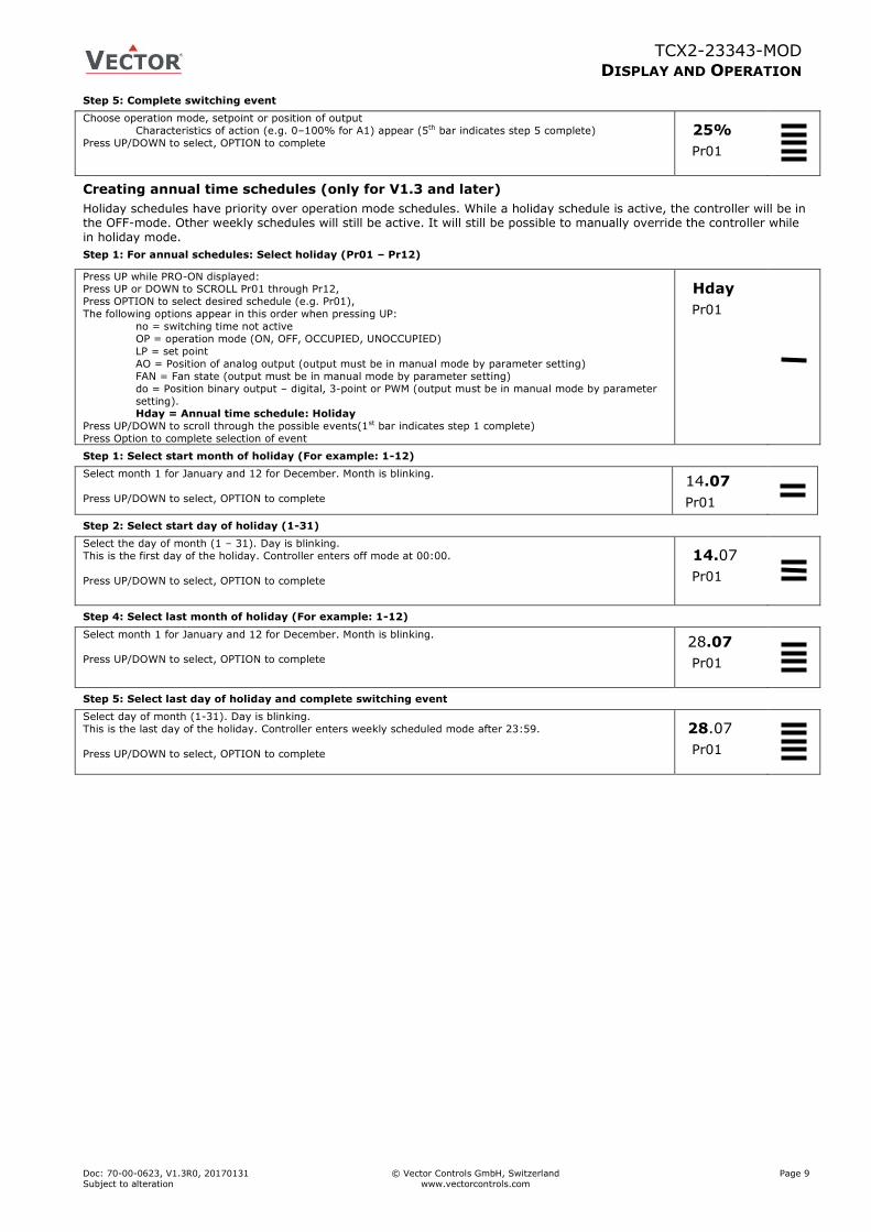
Step 5: Complete switching event
Choose operation mode, setpoint or position of output
Characteristics of action (e.g. 0–100% for A1) appear (5th bar indicates step 5 complete)
Press UP/DOWN to select, OPTION to complete 25%
Pr01
Creating annual time schedules (only for V1.3 and later)
Holiday schedules have priority over operation mode schedules. While a holiday schedule is active, the controller will be in the OFF-mode. Other weekly schedules will still be active. It will still be possible to manually override the controller while
in holiday mode.
Step 1: For annual schedules: Select holiday (Pr01 – Pr12)
Press UP while PRO-ON displayed: Press UP or DOWN to SCROLL Pr01 through Pr12,
Press OPTION to select desired schedule (e.g. Pr01),
The following options appear in this order when pressing UP:
no = switching time not active
OP = operation mode (ON, OFF, OCCUPIED, UNOCCUPIED)
LP = set point
AO = Position of analog output (output must be in manual mode by parameter setting)
FAN = Fan state (output must be in manual mode by parameter setting)
do = Position binary output – digital, 3-point or PWM (output must be in manual mode by parameter
setting). Hday = Annual time schedule: Holiday
Press UP/DOWN to scroll through the possible events(1st bar indicates step 1 complete)
Press Option to complete selection of event
Hday
Pr01
Step 1: Select start month of holiday (For example: 1-12)
Select month 1 for January and 12 for December. Month is blinking.
Press UP/DOWN to select, OPTION to complete
14.07
Pr01
Step 2: Select start day of holiday (1-31)
Select the day of month (1 – 31). Day is blinking.
This is the first day of the holiday. Controller enters off mode at 00:00.
Press UP/DOWN to select, OPTION to complete
14.07
Pr01
Step 4: Select last month of holiday (For example: 1-12)
Select month 1 for January and 12 for December. Month is blinking.
Press UP/DOWN to select, OPTION to complete
28.07
Pr01
Step 5: Select last day of holiday and complete switching event
Select day of month (1-31). Day is blinking.
This is the last day of the holiday. Controller enters weekly scheduled mode after 23:59.
Press UP/DOWN to select, OPTION to complete
28.07
Pr01
TCX2-23343-MOD
DISPLAY AND OPERATION
Doc: 70-00-0623, V1.3R0, 20170131 © Vector Controls GmbH, Switzerland Page 10 Subject to alteration www.vectorcontrols.com
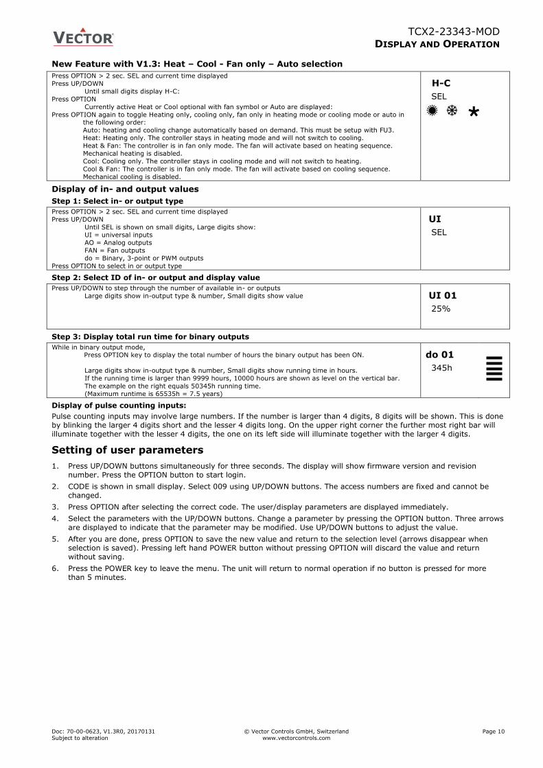
New Feature with V1.3: Heat – Cool - Fan only – Auto selection
Press OPTION > 2 sec. SEL and current time displayed
Press UP/DOWN
Until small digits display H-C:
Press OPTION
Currently active Heat or Cool optional with fan symbol or Auto are displayed:
Press OPTION again to toggle Heating only, cooling only, fan only in heating mode or cooling mode or auto in the following order:
Auto: heating and cooling change automatically based on demand. This must be setup with FU3.
Heat: Heating only. The controller stays in heating mode and will not switch to cooling.
Heat & Fan: The controller is in fan only mode. The fan will activate based on heating sequence.
Mechanical heating is disabled.
Cool: Cooling only. The controller stays in cooling mode and will not switch to heating.
Cool & Fan: The controller is in fan only mode. The fan will activate based on cooling sequence.
Mechanical cooling is disabled.
H-C
SEL
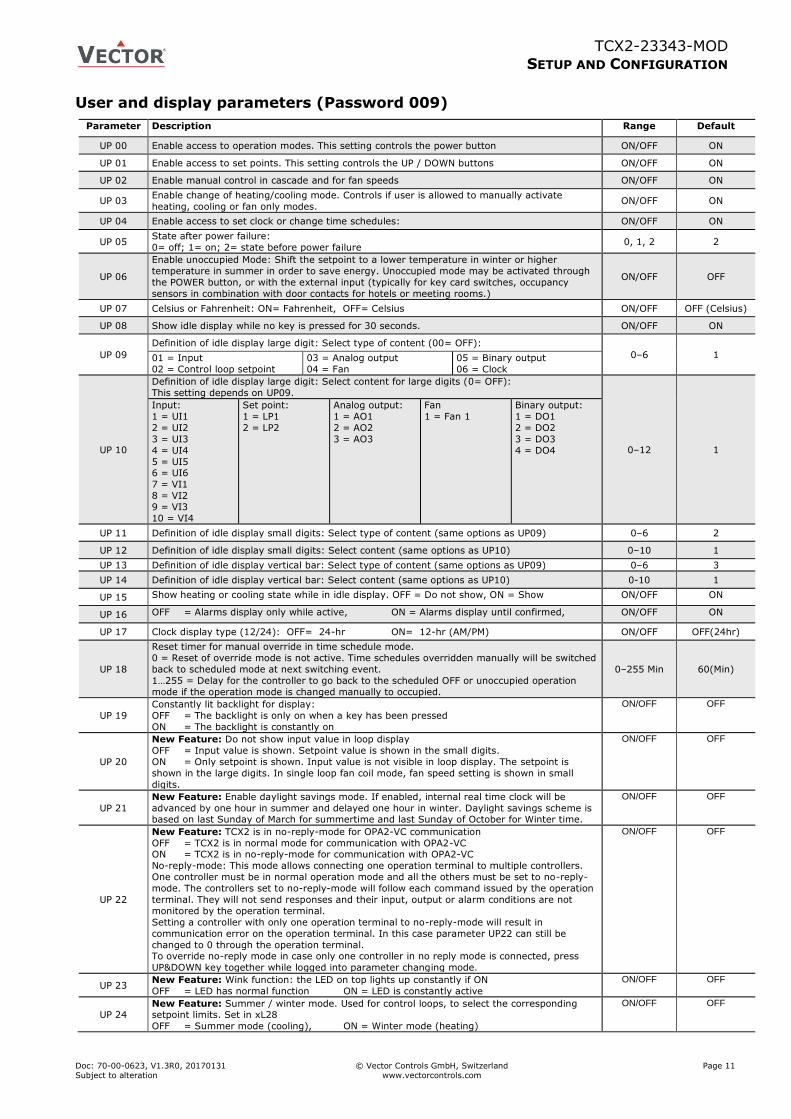
Display of in- and output values
Step 1: Select in- or output type
Press OPTION > 2 sec. SEL and current time displayed
Press UP/DOWN
Until SEL is shown on small digits, Large digits show: UI = universal inputs
AO = Analog outputs
FAN = Fan outputs
do = Binary, 3-point or PWM outputs
Press OPTION to select in or output type
UI
SEL
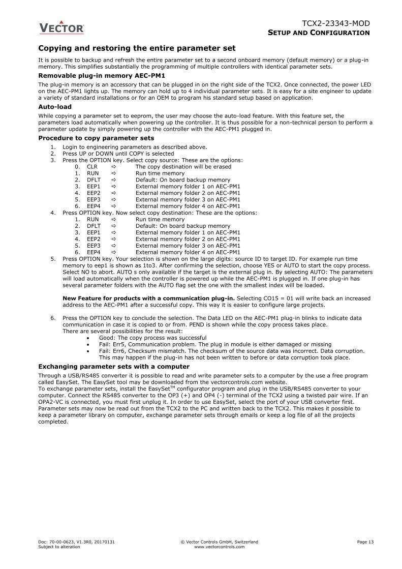
Step 2: Select ID of in- or output and display value
Press UP/DOWN to step through the number of available in- or outputs
Large digits show in-output type & number, Small digits show value UI 01
25%
Step 3: Display total run time for binary outputs
While in binary output mode, Press OPTION key to display the total number of hours the binary output has been ON.
Large digits show in-output type & number, Small digits show running time in hours.
If the running time is larger than 9999 hours, 10000 hours are shown as level on the vertical bar.
The example on the right equals 50345h running time.
(Maximum runtime is 65535h = 7.5 years)
do 01
345h
Display of pulse counting inputs:
Pulse counting inputs may involve large numbers. If the number is larger than 4 digits, 8 digits will be shown. This is done by blinking the larger 4 digits short and the lesser 4 digits long. On the upper right corner the further most right bar will illuminate together with the lesser 4 digits, the one on its left side will illuminate together with the larger 4 digits.
Setting of user parameters
1. Press UP/DOWN buttons simultaneously for three seconds. The display will show firmware version and revision number. Press the OPTION button to start login.
2. CODE is shown in small display. Select 009 using UP/DOWN buttons. The access numbers are fixed and cannot be changed.
3. Press OPTION after selecting the correct code. The user/display parameters are displayed immediately.
4. Select the parameters with the UP/DOWN buttons. Change a parameter by pressing the OPTION button. Three arrows are displayed to indicate that the parameter may be modified. Use UP/DOWN buttons to adjust the value.
5. After you are done, press OPTION to save the new value and return to the selection level (arrows disappear when selection is saved). Pressing left hand POWER button without pressing OPTION will discard the value and return without saving.
6. Press the POWER key to leave the menu. The unit will return to normal operation if no button is pressed for more than 5 minutes.
TCX2-23343-MOD
SETUP AND CONFIGURATION
Doc: 70-00-0623, V1.3R0, 20170131 © Vector Controls GmbH, Switzerland Page 11 Subject to alteration www.vectorcontrols.com
User and display parameters (Password 009)
Parameter Description Range Default
UP 00 Enable access to operation modes. This setting controls the power button ON/OFF ON
UP 01 Enable access to set points. This setting controls the UP / DOWN buttons ON/OFF ON
UP 02 Enable manual control in cascade and for fan speeds ON/OFF ON
UP 03 Enable change of heating/cooling mode. Controls if user is allowed to manually activate
heating, cooling or fan only modes. ON/OFF ON
UP 04 Enable access to set clock or change time schedules: ON/OFF ON
UP 05 State after power failure:
0= off; 1= on; 2= state before power failure 0, 1, 2 2
UP 06
Enable unoccupied Mode: Shift the setpoint to a lower temperature in winter or higher
temperature in summer in order to save energy. Unoccupied mode may be activated through
the POWER button, or with the external input (typically for key card switches, occupancy
sensors in combination with door contacts for hotels or meeting rooms.)
ON/OFF OFF
UP 07 Celsius or Fahrenheit: ON= Fahrenheit, OFF= Celsius ON/OFF OFF (Celsius)
UP 08 Show idle display while no key is pressed for 30 seconds. ON/OFF ON
UP 09
Definition of idle display large digit: Select type of content (00= OFF):
0–6 1 01 = Input
02 = Control loop setpoint
03 = Analog output
04 = Fan
05 = Binary output
06 = Clock
UP 10
Definition of idle display large digit: Select content for large digits (0= OFF):
This setting depends on UP09.
0–12 1
Input:
1 = UI1
2 = UI2
3 = UI3
4 = UI4
5 = UI5 6 = UI6
7 = VI1
8 = VI2
9 = VI3
10 = VI4
Set point:
1 = LP1
2 = LP2
Analog output:
1 = AO1
2 = AO2
3 = AO3
Fan
1 = Fan 1
Binary output:
1 = DO1
2 = DO2
3 = DO3
4 = DO4
UP 11 Definition of idle display small digits: Select type of content (same options as UP09) 0–6 2
UP 12 Definition of idle display small digits: Select content (same options as UP10) 0–10 1
UP 13 Definition of idle display vertical bar: Select type of content (same options as UP09) 0–6 3
UP 14 Definition of idle display vertical bar: Select content (same options as UP10) 0-10 1
UP 15 Show heating or cooling state while in idle display. OFF = Do not show, ON = Show ON/OFF ON
UP 16 OFF = Alarms display only while active, ON = Alarms display until confirmed, ON/OFF ON
UP 17 Clock display type (12/24): OFF= 24-hr ON= 12-hr (AM/PM) ON/OFF OFF(24hr)
UP 18
Reset timer for manual override in time schedule mode.
0 = Reset of override mode is not active. Time schedules overridden manually will be switched
back to scheduled mode at next switching event.
1…255 = Delay for the controller to go back to the scheduled OFF or unoccupied operation
mode if the operation mode is changed manually to occupied.
0–255 Min 60(Min)
UP 19
Constantly lit backlight for display:
OFF = The backlight is only on when a key has been pressed
ON = The backlight is constantly on
ON/OFF OFF
UP 20
New Feature: Do not show input value in loop display
OFF = Input value is shown. Setpoint value is shown in the small digits.
ON = Only setpoint is shown. Input value is not visible in loop display. The setpoint is
shown in the large digits. In single loop fan coil mode, fan speed setting is shown in small
digits.
ON/OFF OFF
UP 21
New Feature: Enable daylight savings mode. If enabled, internal real time clock will be
advanced by one hour in summer and delayed one hour in winter. Daylight savings scheme is based on last Sunday of March for summertime and last Sunday of October for Winter time.
ON/OFF OFF
UP 22
New Feature: TCX2 is in no-reply-mode for OPA2-VC communication
OFF = TCX2 is in normal mode for communication with OPA2-VC ON = TCX2 is in no-reply-mode for communication with OPA2-VC
No-reply-mode: This mode allows connecting one operation terminal to multiple controllers.
One controller must be in normal operation mode and all the others must be set to no-reply-
mode. The controllers set to no-reply-mode will follow each command issued by the operation
terminal. They will not send responses and their input, output or alarm conditions are not
monitored by the operation terminal.
Setting a controller with only one operation terminal to no-reply-mode will result in
communication error on the operation terminal. In this case parameter UP22 can still be
changed to 0 through the operation terminal. To override no-reply mode in case only one controller in no reply mode is connected, press
UP&DOWN key together while logged into parameter changing mode.
ON/OFF OFF
UP 23 New Feature: Wink function: the LED on top lights up constantly if ON
OFF = LED has normal function ON = LED is constantly active
ON/OFF OFF
UP 24 New Feature: Summer / winter mode. Used for control loops, to select the corresponding setpoint limits. Set in xL28
OFF = Summer mode (cooling), ON = Winter mode (heating)
ON/OFF OFF

TCX2-23343-MOD
SETUP AND CONFIGURATION
Doc: 70-00-0623, V1.3R0, 20170131 © Vector Controls GmbH, Switzerland Page 12 Subject to alteration www.vectorcontrols.com
Setting parameters to configure the controller
TCX2 is a programmable controller with the flexibility to fit a wide range of applications. The control operation is defined by parameters. They can be set using the standard operation terminal. There are two levels:
1. User/display parameters (default password 0009)
2. Control parameters (default password 0241)
Recommended set-up procedure:
1. Set jumpers on the back of the controller for inputs and outputs
2. Connect power supply and inputs
3. Make sure Celsius – Fahrenheit settings are correct (UP07)
4. Program input parameters
5. Program control parameters
6. Program output parameters
7. Program auxiliary functions and user settings
8. Test function of unit
9. Switch off power
10. Connect outputs
11. Reconnect power
12. Test control loop
Parameters are grouped according to modules:
Module Description PW
UP User and display parameters 009
LP Control loops Lp1 to Lp2
241
UI Input configuration: 1U to 10U
AL Alarm configuration: 1AL to 8AL
FU Special functions Fu1 to Fu5
AO Analog output configuration, AO1 to AO3
FAN Fan output configuration FAN1 to FAN2
DO Binary output configuration, do1 to do6
Co Communication setup (refer to separate communication brochure)
COPY copy mode to copy full parameter sets between run, default and external memory with up to 4 saving locations (AEC-PM1)
How to change parameters
Note: Access to parameters may be inhibited by the supplier of the controller. In this case the below mentioned procedure will not work. 1. Press UP/DOWN buttons simultaneously for three seconds. The display will show firmware version and revision
number. Press the OPTION button to start login.
2. CODE is shown in small display. Select 241 or the number provided by your supplier using the UP or DOWN button. These are the default access numbers, your supplier may have changed those numbers or blocked access to the parameters completely. Parameters should only be changed by authorized personnel.
3. Press OPTION after selecting the correct code. The user/display parameters are displayed immediately.
4. Once logged in with 241 control modules are displayed (UI, AL, LP, AO, FAN, DO, CO etc.) – select with UP/DOWN and open with OPTION. Then select the ID with UP/DOWN keys: 1U, 2U, 3U etc., open with OPTION. As soon as the module is open its parameters are displayed.
5. Select the parameters with the UP/DOWN buttons. Change a parameter by pressing the OPTION button. Three arrows are displayed to indicate that the parameter may be modified. Use UP/DOWN buttons to adjust the value.
6. After you are done, press OPTION to save the new value and return to the selection level (arrows disappear when selection is saved). Pressing left hand POWER button without pressing OPTION will discard the value and return without saving.
7. Press POWER to leave parameter selection and return to control module selection.
8. Press the POWER to leave the menu. The unit will return to normal operation, if no button is pressed for more than 5 minutes.
How to select active alarms on outputs and special functions or weekdays in time schedules
1. Select the parameter as described above
2. Press OPTION to start selecting alarms. AL 1 is now shown in the large digits.
3. Press UP to select the alarm 1, press DOWN to deselect the alarm 1. A selected alarm is visible by a dark triangle on the bottom line of the LCD. The output or function will activate if the corresponding alarm is triggered.
4. Press OPTION to step to alarm 2. Repeatedly press OPTION key to step through all available alarms and select or deselect them by pressing UP or DOWN.
5. Press POWER to leave the alarm selection routine and return to the parameter selection level.
TCX2-23343-MOD
SETUP AND CONFIGURATION
Doc: 70-00-0623, V1.3R0, 20170131 © Vector Controls GmbH, Switzerland Page 13 Subject to alteration www.vectorcontrols.com
Copying and restoring the entire parameter set
It is possible to backup and refresh the entire parameter set to a second onboard memory (default memory) or a plug-in memory. This simplifies substantially the programming of multiple controllers with identical parameter sets.
Removable plug-in memory AEC-PM1
The plug-in memory is an accessory that can be plugged in on the right side of the TCX2. Once connected, the power LED on the AEC-PM1 lights up. The memory can hold up to 4 individual parameter sets. It is easy for a site engineer to update a variety of standard installations or for an OEM to program his standard setup based on application.
Auto-load
While copying a parameter set to eeprom, the user may choose the auto-load feature. With this feature set, the parameters load automatically when powering up the controller. It is thus possible for a non-technical person to perform a parameter update by simply powering up the controller with the AEC-PM1 plugged in.
Procedure to copy parameter sets
1. Login to engineering parameters as described above. 2. Press UP or DOWN until COPY is selected 3. Press the OPTION key. Select copy source: These are the options:
0. CLR The copy destination will be erased 1. RUN Run time memory 2. DFLT Default: On board backup memory 3. EEP1 External memory folder 1 on AEC-PM1 4. EEP2 External memory folder 2 on AEC-PM1 5. EEP3 External memory folder 3 on AEC-PM1 6. EEP4 External memory folder 4 on AEC-PM1
4. Press OPTION key. Now select copy destination: These are the options: 1. RUN Run time memory 2. DFLT Default: On board backup memory 3. EEP1 External memory folder 1 on AEC-PM1 4. EEP2 External memory folder 2 on AEC-PM1 5. EEP3 External memory folder 3 on AEC-PM1 6. EEP4 External memory folder 4 on AEC-PM1
5. Press OPTION key. Your selection is shown on the large digits: source ID to target ID. For example run time memory to eep1 is shown as 1to3. After confirming the selection, choose YES or AUTO to start the copy process. Select NO to abort. AUTO s only available if the target is the external plug in. By selecting AUTO: The parameters will load automatically when the controller is powered up while the AEC-PM1 is plugged in. If one plug-in has several parameter folders with the AUTO flag set the one with the smallest index will be loaded. New Feature for products with a communication plug-in. Selecting CO15 = 01 will write back an increased address to the AEC-PM1 after a successful copy. This way it is easier to configure large projects.
6. Press the OPTION key to conclude the selection. The Data LED on the AEC-PM1 plug-in blinks to indicate data communication in case it is copied to or from. PEND is shown while the copy process takes place. There are several possibilities for the result:
Good: The copy process was successful Fail: Err5, Communication problem. The plug in module is either damaged or missing Fail: Err6, Checksum mismatch. The checksum of the source data was incorrect. Data corruption.
This may happen if the plug-in has not been written to before or data corruption took place.
Exchanging parameter sets with a computer
Through a USB/RS485 converter it is possible to read and write parameter sets to a computer by the use a free program called EasySet. The EasySet tool may be downloaded from the vectorcontrols.com website. To exchange parameter sets, install the EasySetTM configurator program and plug in the USB/RS485 converter to your computer. Connect the RS485 converter to the OP3 (+) and OP4 (-) terminal of the TCX2 using a twisted pair wire. If an OPA2-VC is connected, you must first unplug it. In order to use EasySet, select the port of your USB converter first. Parameter sets may now be read out from the TCX2 to the PC and written back to the TCX2. This makes it possible to keep a parameter library on computer, exchange parameter sets through emails or keep a log file of all the projects completed.
TCX2-23343-MOD
INPUT AND ALARM CONFIGURATION
Doc: 70-00-0623, V1.3R0, 20170131 © Vector Controls GmbH, Switzerland Page 14 Subject to alteration www.vectorcontrols.com
Input & alarm/interlock configuration
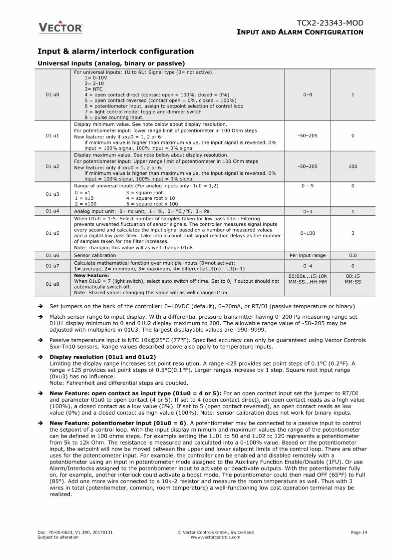
Universal inputs (analog, binary or passive)
01 u0
For universal inputs: 1U to 6U: Signal type (0= not active): 1= 0-10V
2= 2-10
3= NTC
4 = open contact direct (contact open = 100%, closed = 0%)
5 = open contact reversed (contact open = 0%, closed = 100%)
6 = potentiometer input, assign to setpoint selection of control loop
7 = light control mode: toggle and dimmer switch
8 = pulse counting input.
0–8 1
01 u1
Display minimum value. See note below about display resolution.
For potentiometer input: lower range limit of potentiometer in 100 Ohm steps
New feature: only if xxu0 = 1, 2 or 6:
if minimum value is higher than maximum value, the input signal is reversed. 0% input = 100% signal, 100% input = 0% signal
-50–205 0
01 u2
Display maximum value. See note below about display resolution.
For potentiometer input: Upper range limit of potentiometer in 100 Ohm steps
New feature: only if xxu0 = 1, 2 or 6: if minimum value is higher than maximum value, the input signal is reversed. 0%
input = 100% signal, 100% input = 0% signal
-50–205 100
01 u3
Range of universal inputs (For analog inputs only: 1u0 = 1,2) 0 – 5 0
0 = x1 1 = x10
2 = x100
3 = square root 4 = square root x 10
5 = square root x 100
01 u4 Analog input unit: 0= no unit, 1= %, 2= °C /°F, 3= Pa 0–3 1
01 u5
When 01u0 = 1-5: Select number of samples taken for low pass filter: Filtering
prevents unwanted fluctuation of sensor signals. The controller measures signal inputs
every second and calculates the input signal based on a number of measured values
and a digital low pass filter. Take into account that signal reaction delays as the number
of samples taken for the filter increases.
Note: changing this value will as well change 01u8
0–100 3
01 u6 Sensor calibration Per input range 0.0
01 u7 Calculate mathematical function over multiple inputs (0=not active):
1= average, 2= minimum, 3= maximum, 4= differential UI(n) – UI(n-1) 0–4 0
01 u8
New Feature:
When 01u0 = 7 (light switch), select auto switch off time. Set to 0, if output should not
automatically switch off.
Note: Shared value: changing this value will as well change 01u5
00:00s...15:10h
MM:SS...HH:MM
00:15
MM:SS
Set jumpers on the back of the controller: 0–10VDC (default), 0–20mA, or RT/DI (passive temperature or binary)
Match sensor range to input display. With a differential pressure transmitter having 0–200 Pa measuring range set 01U1 display minimum to 0 and 01U2 display maximum to 200. The allowable range value of -50–205 may be adjusted with multipliers in 01U3. The largest displayable values are -990–9999.
Passive temperature input is NTC 10k@25°C (77°F). Specified accuracy can only be guaranteed using Vector Controls Sxx-Tn10 sensors. Range values described above also apply to temperature inputs.
Display resolution (01u1 and 01u2) Limiting the display range increases set point resolution. A range <25 provides set point steps of 0.1°C (0.2°F). A range <125 provides set point steps of 0.5°C(0.1°F). Larger ranges increase by 1 step. Square root input range (0xu3) has no influence. Note: Fahrenheit and differential steps are doubled.
New Feature: open contact as input type (01u0 = 4 or 5): For an open contact input set the jumper to RT/DI and parameter 01u0 to open contact (4 or 5). If set to 4 (open contact direct), an open contact reads as a high value (100%), a closed contact as a low value (0%). If set to 5 (open contact reversed), an open contact reads as low value (0%) and a closed contact as high value (100%). Note: sensor calibration does not work for binary inputs.
New Feature: potentiometer input (01u0 = 6). A potentiometer may be connected to a passive input to control the setpoint of a control loop. With the input display minimum and maximum values the range of the potentiometer can be defined in 100 ohms steps. For example setting the 1u01 to 50 and 1u02 to 120 represents a potentiometer from 5k to 12k Ohm. The resistance is measured and calculated into a 0-100% value. Based on the potentiometer input, the setpoint will now be moved between the upper and lower setpoint limits of the control loop. There are other uses for the potentiometer input. For example, the controller can be enabled and disabled remotely with a potentiometer using an input in potentiometer mode assigned to the Auxiliary Function Enable/Disable (1FU). Or use Alarm/Interlocks assigned to the potentiometer input to activate or deactivate outputs. With the potentiometer fully on, for example, another interlock could activate a boost mode. The potentiometer could then read OFF (65°F) to Full (85°). Add one more wire connected to a 10k-2 resistor and measure the room temperature as well. Thus with 3 wires in total (potentiometer, common, room temperature) a well-functioning low cost operation terminal may be realized.
TCX2-23343-MOD
INPUT AND ALARM CONFIGURATION
Doc: 70-00-0623, V1.3R0, 20170131 © Vector Controls GmbH, Switzerland Page 15 Subject to alteration www.vectorcontrols.com
New Feature: light control mode: toggle and dimmer switch (01u0 = 7): Manage lighting with TCX2 and special functions such as alarms, time schedules and automatic occupied/unoccupied mode switch can be used for occupant convenience and to reduce lighting costs. With this feature building light is controlled by using push-button switches in the room connected to passive inputs on TCX2. A passive inputs is assigned directly to an output connected to a relay for the light. This is achieved by setting xd01 to 9. An analog output is assigned directly to an input by assigning xA00 to 7. Use binary outputs for on/off lights or add an analog output for dimming. Pressing the push-button switch for less than 2 seconds will toggle the binary output. For dimming, pressing the push-button switch for longer than 2 seconds will change the input value by 10% per second from 0% to 100% and again back to 0%.
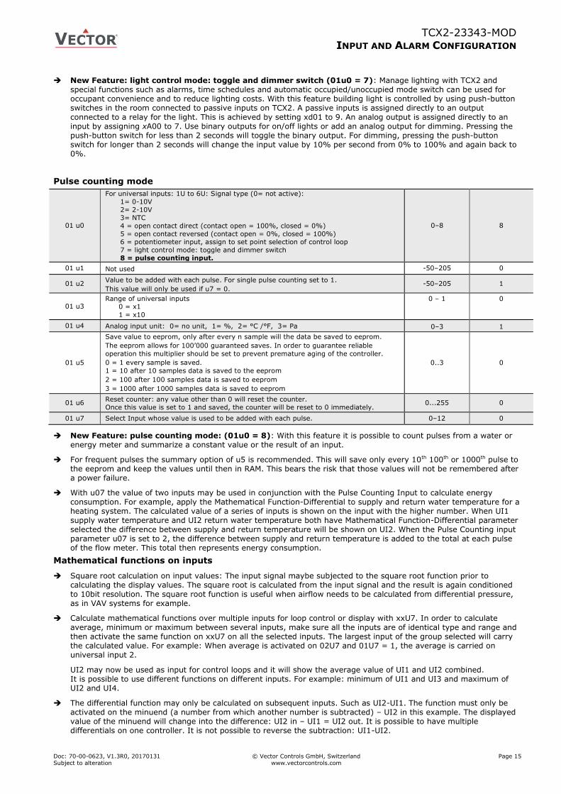
Pulse counting mode
01 u0
For universal inputs: 1U to 6U: Signal type (0= not active):
1= 0-10V
2= 2-10V
3= NTC
4 = open contact direct (contact open = 100%, closed = 0%)
5 = open contact reversed (contact open = 0%, closed = 100%)
6 = potentiometer input, assign to set point selection of control loop
7 = light control mode: toggle and dimmer switch
8 = pulse counting input.
0–8 8
01 u1 Not used -50–205 0
01 u2 Value to be added with each pulse. For single pulse counting set to 1.
This value will only be used if u7 = 0. -50–205 1
01 u3 Range of universal inputs
0 = x1
1 = x10
0 – 1 0
01 u4 Analog input unit: 0= no unit, 1= %, 2= °C /°F, 3= Pa 0–3 1
01 u5
Save value to eeprom, only after every n sample will the data be saved to eeprom.
The eeprom allows for 100’000 guaranteed saves. In order to guarantee reliable
operation this multiplier should be set to prevent premature aging of the controller.
0 = 1 every sample is saved.
1 = 10 after 10 samples data is saved to the eeprom
2 = 100 after 100 samples data is saved to eeprom
3 = 1000 after 1000 samples data is saved to eeprom
0..3 0
01 u6 Reset counter: any value other than 0 will reset the counter.
Once this value is set to 1 and saved, the counter will be reset to 0 immediately. 0...255 0
01 u7 Select Input whose value is used to be added with each pulse. 0–12 0
New Feature: pulse counting mode: (01u0 = 8): With this feature it is possible to count pulses from a water or energy meter and summarize a constant value or the result of an input.
For frequent pulses the summary option of u5 is recommended. This will save only every 10th 100th or 1000th pulse to the eeprom and keep the values until then in RAM. This bears the risk that those values will not be remembered after a power failure.
With u07 the value of two inputs may be used in conjunction with the Pulse Counting Input to calculate energy consumption. For example, apply the Mathematical Function-Differential to supply and return water temperature for a heating system. The calculated value of a series of inputs is shown on the input with the higher number. When UI1 supply water temperature and UI2 return water temperature both have Mathematical Function-Differential parameter selected the difference between supply and return temperature will be shown on UI2. When the Pulse Counting input parameter u07 is set to 2, the difference between supply and return temperature is added to the total at each pulse of the flow meter. This total then represents energy consumption.
Mathematical functions on inputs
Square root calculation on input values: The input signal maybe subjected to the square root function prior to calculating the display values. The square root is calculated from the input signal and the result is again conditioned to 10bit resolution. The square root function is useful when airflow needs to be calculated from differential pressure, as in VAV systems for example.
Calculate mathematical functions over multiple inputs for loop control or display with xxU7. In order to calculate average, minimum or maximum between several inputs, make sure all the inputs are of identical type and range and then activate the same function on xxU7 on all the selected inputs. The largest input of the group selected will carry the calculated value. For example: When average is activated on 02U7 and 01U7 = 1, the average is carried on universal input 2.
UI2 may now be used as input for control loops and it will show the average value of UI1 and UI2 combined. It is possible to use different functions on different inputs. For example: minimum of UI1 and UI3 and maximum of UI2 and UI4.
The differential function may only be calculated on subsequent inputs. Such as UI2-UI1. The function must only be activated on the minuend (a number from which another number is subtracted) – UI2 in this example. The displayed value of the minuend will change into the difference: UI2 in – UI1 = UI2 out. It is possible to have multiple differentials on one controller. It is not possible to reverse the subtraction: UI1-UI2.
TCX2-23343-MOD
INPUT AND ALARM CONFIGURATION
Doc: 70-00-0623, V1.3R0, 20170131 © Vector Controls GmbH, Switzerland Page 16 Subject to alteration www.vectorcontrols.com
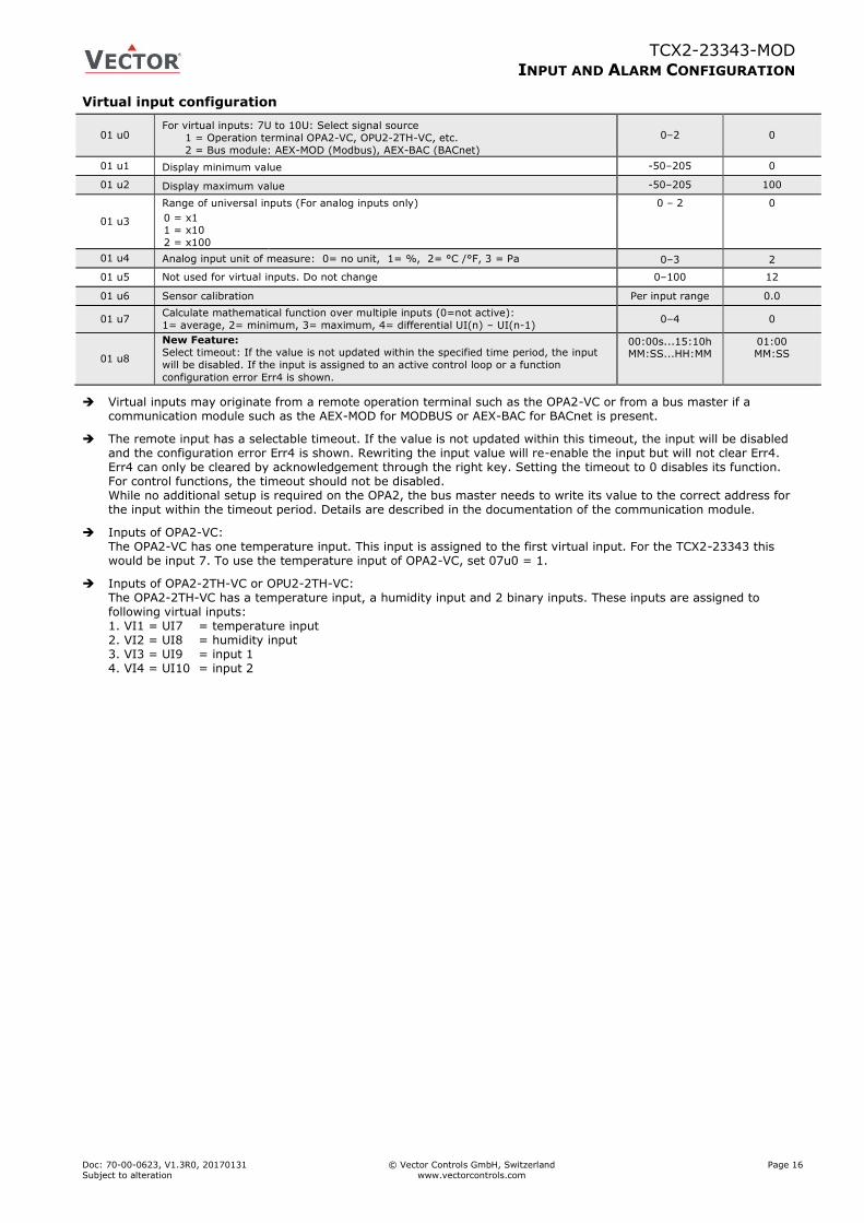
Virtual input configuration
01 u0 For virtual inputs: 7U to 10U: Select signal source
1 = Operation terminal OPA2-VC, OPU2-2TH-VC, etc.
2 = Bus module: AEX-MOD (Modbus), AEX-BAC (BACnet)
0–2 0
01 u1 Display minimum value -50–205 0
01 u2 Display maximum value -50–205 100
01 u3
Range of universal inputs (For analog inputs only) 0 – 2 0
0 = x1 1 = x10
2 = x100
01 u4 Analog input unit of measure: 0= no unit, 1= %, 2= °C /°F, 3 = Pa 0–3 2
01 u5 Not used for virtual inputs. Do not change 0–100 12
01 u6 Sensor calibration Per input range 0.0
01 u7 Calculate mathematical function over multiple inputs (0=not active):
1= average, 2= minimum, 3= maximum, 4= differential UI(n) – UI(n-1) 0–4 0
01 u8
New Feature:
Select timeout: If the value is not updated within the specified time period, the input
will be disabled. If the input is assigned to an active control loop or a function
configuration error Err4 is shown.
00:00s...15:10h MM:SS...HH:MM
01:00 MM:SS
Virtual inputs may originate from a remote operation terminal such as the OPA2-VC or from a bus master if a communication module such as the AEX-MOD for MODBUS or AEX-BAC for BACnet is present.
The remote input has a selectable timeout. If the value is not updated within this timeout, the input will be disabled and the configuration error Err4 is shown. Rewriting the input value will re-enable the input but will not clear Err4. Err4 can only be cleared by acknowledgement through the right key. Setting the timeout to 0 disables its function. For control functions, the timeout should not be disabled. While no additional setup is required on the OPA2, the bus master needs to write its value to the correct address for the input within the timeout period. Details are described in the documentation of the communication module.
Inputs of OPA2-VC: The OPA2-VC has one temperature input. This input is assigned to the first virtual input. For the TCX2-23343 this would be input 7. To use the temperature input of OPA2-VC, set 07u0 = 1.
Inputs of OPA2-2TH-VC or OPU2-2TH-VC: The OPA2-2TH-VC has a temperature input, a humidity input and 2 binary inputs. These inputs are assigned to following virtual inputs: 1. VI1 = UI7 = temperature input 2. VI2 = UI8 = humidity input 3. VI3 = UI9 = input 1 4. VI4 = UI10 = input 2
TCX2-23343-MOD
INPUT AND ALARM CONFIGURATION
Doc: 70-00-0623, V1.3R0, 20170131 © Vector Controls GmbH, Switzerland Page 17 Subject to alteration www.vectorcontrols.com
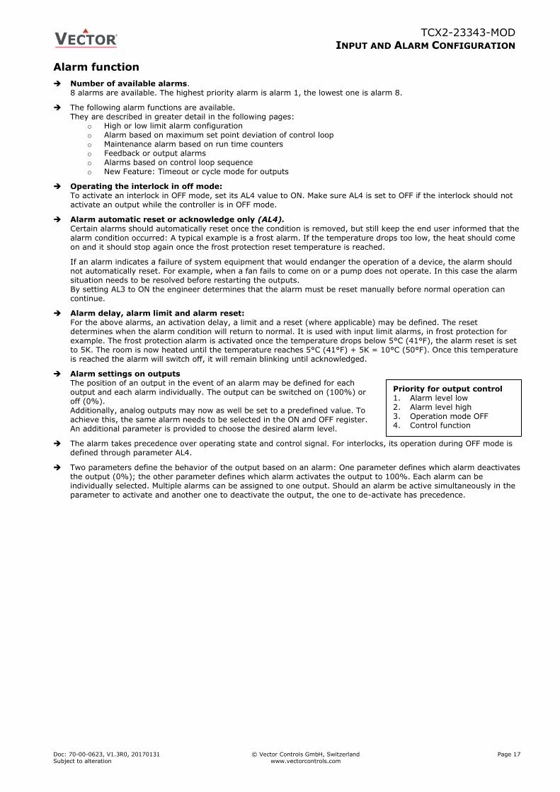
Priority for output control 1. Alarm level low 2. Alarm level high 3. Operation mode OFF 4. Control function
Alarm function
Number of available alarms. 8 alarms are available. The highest priority alarm is alarm 1, the lowest one is alarm 8.
The following alarm functions are available. They are described in greater detail in the following pages:
o High or low limit alarm configuration o Alarm based on maximum set point deviation of control loop o Maintenance alarm based on run time counters o Feedback or output alarms o Alarms based on control loop sequence o New Feature: Timeout or cycle mode for outputs
Operating the interlock in off mode: To activate an interlock in OFF mode, set its AL4 value to ON. Make sure AL4 is set to OFF if the interlock should not activate an output while the controller is in OFF mode.
Alarm automatic reset or acknowledge only (AL4). Certain alarms should automatically reset once the condition is removed, but still keep the end user informed that the
alarm condition occurred: A typical example is a frost alarm. If the temperature drops too low, the heat should come on and it should stop again once the frost protection reset temperature is reached.
If an alarm indicates a failure of system equipment that would endanger the operation of a device, the alarm should not automatically reset. For example, when a fan fails to come on or a pump does not operate. In this case the alarm situation needs to be resolved before restarting the outputs. By setting AL3 to ON the engineer determines that the alarm must be reset manually before normal operation can continue.
Alarm delay, alarm limit and alarm reset: For the above alarms, an activation delay, a limit and a reset (where applicable) may be defined. The reset determines when the alarm condition will return to normal. It is used with input limit alarms, in frost protection for example. The frost protection alarm is activated once the temperature drops below 5°C (41°F), the alarm reset is set to 5K. The room is now heated until the temperature reaches 5°C (41°F) + 5K = 10°C (50°F). Once this temperature is reached the alarm will switch off, it will remain blinking until acknowledged.
Alarm settings on outputs The position of an output in the event of an alarm may be defined for each output and each alarm individually. The output can be switched on (100%) or off (0%). Additionally, analog outputs may now as well be set to a predefined value. To achieve this, the same alarm needs to be selected in the ON and OFF register. An additional parameter is provided to choose the desired alarm level.
The alarm takes precedence over operating state and control signal. For interlocks, its operation during OFF mode is defined through parameter AL4.
Two parameters define the behavior of the output based on an alarm: One parameter defines which alarm deactivates the output (0%); the other parameter defines which alarm activates the output to 100%. Each alarm can be individually selected. Multiple alarms can be assigned to one output. Should an alarm be active simultaneously in the parameter to activate and another one to deactivate the output, the one to de-activate has precedence.
TCX2-23343-MOD
INPUT AND ALARM CONFIGURATION
Doc: 70-00-0623, V1.3R0, 20170131 © Vector Controls GmbH, Switzerland Page 18 Subject to alteration www.vectorcontrols.com
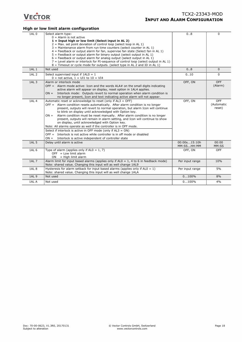
High or low limit alarm configuration
1AL 0 Select alarm type:
0 = Alarm is not active
1 = Input high or low limit (Select input in AL 2)
2 = Max. set point deviation of control loop (select loop in AL 1)
3 = Maintenance alarm from run time counters (select counter in AL 1)
4 = Feedback or output alarm for fan, supervise fan state (Select fan in AL 1)
5 = Feedback or output alarm for binary output (select output in AL 1) 6 = Feedback or output alarm for analog output (select output in AL 1)
7 = Level alarm or interlock for PI-sequence of control loop (select output in AL 1)
8 = Timeout or cycle mode for outputs. (select type in AL 2 and ID in AL 1)
0…8 0
1AL 1 Not used 0…8 0
1AL 2 Select supervised input if 1AL0 = 1
0 = not active, 1 = UI1 to 10 = VI4
0…10 0
1AL 3 Alarm or interlock mode
OFF = Alarm mode active: Icon and the words ALA# on the small digits indicating
active alarm will appear on display, reset option in 1AL4 applies.
ON = Interlock mode: Outputs revert to normal operation when alarm condition is
no longer present, Icon and text indicating active alarm will not appear.
OFF, ON OFF
(Alarm)
1AL 4 Automatic reset or acknowledge to reset (only if AL3 = OFF)
OFF = Alarm condition resets automatically. After alarm condition is no longer
present, outputs will revert to normal operation, but alarm Icon will continue
to blink on display until acknowledged with Option key.
ON = Alarm condition must be reset manually. After alarm condition is no longer
present, outputs will remain in alarm setting, and Icon will continue to show
on display, until acknowledged with Option key.
Note: All alarms operate as well if the controller is in OFF mode.
OFF, ON OFF
(Automatic
reset)
Select if interlock is active in OFF mode (only if AL3 = ON)
OFF = Interlock is not active while controller is in off mode or disabled
ON = Interlock is active independent of controller state
1AL 5 Delay until alarm is active 00:00s...15:10h
MM:SS...HH:MM
00:00
MM:SS
1AL 6 Type of alarm (applies only if AL0 = 1, 7)
OFF = Low limit alarm
ON = High limit alarm
OFF, ON OFF
1AL 7 Alarm limit for input based alarms (applies only if AL0 = 1, 4 to 6 in feedback mode)
Note: shared value. Changing this input will as well change 1AL9
Per input range 10%
1AL 8 Hysteresis for alarm setback for input based alarms (applies only if AL0 = 1)
Note: shared value. Changing this input will as well change 1ALA
Per input range 5%
1AL 9 Not used 0...100% 8%
1AL A Not used 0...100% 4%
TCX2-23343-MOD
INPUT AND ALARM CONFIGURATION
Doc: 70-00-0623, V1.3R0, 20170131 © Vector Controls GmbH, Switzerland Page 19 Subject to alteration www.vectorcontrols.com
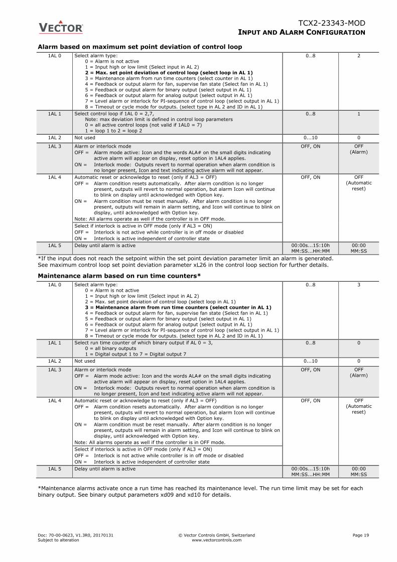
Alarm based on maximum set point deviation of control loop
1AL 0 Select alarm type:
0 = Alarm is not active
1 = Input high or low limit (Select input in AL 2)
2 = Max. set point deviation of control loop (select loop in AL 1)
3 = Maintenance alarm from run time counters (select counter in AL 1)
4 = Feedback or output alarm for fan, supervise fan state (Select fan in AL 1)
5 = Feedback or output alarm for binary output (select output in AL 1) 6 = Feedback or output alarm for analog output (select output in AL 1)
7 = Level alarm or interlock for PI-sequence of control loop (select output in AL 1)
8 = Timeout or cycle mode for outputs. (select type in AL 2 and ID in AL 1)
0…8 2
1AL 1 Select control loop if 1AL 0 = 2,7,
Note: max deviation limit is defined in control loop parameters 0 = all active control loops (not valid if 1AL0 = 7)
1 = loop 1 to 2 = loop 2
0…8 1
1AL 2 Not used 0...10 0
1AL 3 Alarm or interlock mode
OFF = Alarm mode active: Icon and the words ALA# on the small digits indicating
active alarm will appear on display, reset option in 1AL4 applies.
ON = Interlock mode: Outputs revert to normal operation when alarm condition is
no longer present, Icon and text indicating active alarm will not appear.
OFF, ON OFF
(Alarm)
1AL 4 Automatic reset or acknowledge to reset (only if AL3 = OFF)
OFF = Alarm condition resets automatically. After alarm condition is no longer
present, outputs will revert to normal operation, but alarm Icon will continue
to blink on display until acknowledged with Option key.
ON = Alarm condition must be reset manually. After alarm condition is no longer
present, outputs will remain in alarm setting, and Icon will continue to blink on
display, until acknowledged with Option key.
Note: All alarms operate as well if the controller is in OFF mode.
OFF, ON OFF
(Automatic
reset)
Select if interlock is active in OFF mode (only if AL3 = ON)
OFF = Interlock is not active while controller is in off mode or disabled
ON = Interlock is active independent of controller state
1AL 5 Delay until alarm is active 00:00s...15:10h
MM:SS...HH:MM
00:00
MM:SS
*If the input does not reach the setpoint within the set point deviation parameter limit an alarm is generated. See maximum control loop set point deviation parameter xL26 in the control loop section for further details.
Maintenance alarm based on run time counters*
1AL 0 Select alarm type:
0 = Alarm is not active
1 = Input high or low limit (Select input in AL 2)
2 = Max. set point deviation of control loop (select loop in AL 1)
3 = Maintenance alarm from run time counters (select counter in AL 1)
4 = Feedback or output alarm for fan, supervise fan state (Select fan in AL 1)
5 = Feedback or output alarm for binary output (select output in AL 1)
6 = Feedback or output alarm for analog output (select output in AL 1)
7 = Level alarm or interlock for PI-sequence of control loop (select output in AL 1)
8 = Timeout or cycle mode for outputs. (select type in AL 2 and ID in AL 1)
0…8 3
1AL 1 Select run time counter of which binary output if AL 0 = 3,
0 = all binary outputs
1 = Digital output 1 to 7 = Digital output 7
0…8 0
1AL 2 Not used 0...10 0
1AL 3 Alarm or interlock mode
OFF = Alarm mode active: Icon and the words ALA# on the small digits indicating
active alarm will appear on display, reset option in 1AL4 applies.
ON = Interlock mode: Outputs revert to normal operation when alarm condition is
no longer present, Icon and text indicating active alarm will not appear.
OFF, ON OFF
(Alarm)
1AL 4 Automatic reset or acknowledge to reset (only if AL3 = OFF)
OFF = Alarm condition resets automatically. After alarm condition is no longer
present, outputs will revert to normal operation, but alarm Icon will continue
to blink on display until acknowledged with Option key.
ON = Alarm condition must be reset manually. After alarm condition is no longer
present, outputs will remain in alarm setting, and Icon will continue to blink on
display, until acknowledged with Option key.
Note: All alarms operate as well if the controller is in OFF mode.
OFF, ON OFF
(Automatic
reset)
Select if interlock is active in OFF mode (only if AL3 = ON)
OFF = Interlock is not active while controller is in off mode or disabled
ON = Interlock is active independent of controller state
1AL 5 Delay until alarm is active 00:00s...15:10h
MM:SS...HH:MM
00:00
MM:SS
*Maintenance alarms activate once a run time has reached its maintenance level. The run time limit may be set for each binary output. See binary output parameters xd09 and xd10 for details.

TCX2-23343-MOD
INPUT AND ALARM CONFIGURATION
Doc: 70-00-0623, V1.3R0, 20170131 © Vector Controls GmbH, Switzerland Page 20 Subject to alteration www.vectorcontrols.com
Feedback or output alarms
1AL 0 Select alarm type:
0 = Alarm is not active
1 = Input high or low limit (Select input in AL 2)
2 = Max. set point deviation of control loop (select loop in AL 1)
3 = Maintenance alarm from run time counters (select counter in AL 1)
4 = Feedback or output alarm for fan, supervise fan state (Select fan in AL 1)
5 = Feedback or output alarm for binary output (select output in AL 1) 6 = Feedback or output alarm for analog output (select output in AL 1)
7 = Level alarm or interlock for PI-sequence of control loop (select output in AL 1)
8 = Timeout or cycle mode for outputs. (select type in AL 2 and ID in AL 1)
0…8 4 - 6
1AL 1 Select fan, binary or analog output if 1AL 0 = 4, 5, 6, 8
0 = Interlock or alarm not active
1..x = selected output
0…8 1
1AL 2 Select supervised input or activate output alarm if 1AL0 = 4, 5, 6:
0 = Output alarm, 1 = UI1 to 10 = VI4
0...10 0
1AL 3 Alarm or interlock mode
OFF = Alarm mode active: Icon and the words ALA# on the small digits indicating active
alarm will appear on display, reset option in 1AL4 applies.
ON = Interlock mode: Outputs revert to normal operation when alarm condition is no
longer present, Icon and text indicating active alarm will not appear.
OFF, ON OFF
(Alarm)
1AL 4 Automatic reset or acknowledge to reset (only if AL3 = OFF)
OFF = Alarm condition resets automatically. After alarm condition is no longer present,
outputs will revert to normal operation, but alarm Icon will continue to blink on
display until acknowledged with Option key.
ON = Alarm condition must be reset manually. After alarm condition is no longer present,
outputs will remain in alarm setting, and Icon will continue to blink on display, until
acknowledged with Option key.
Note: All alarms operate as well if the controller is in OFF mode.
OFF, ON OFF
(Automatic
reset)
Select if interlock is active in OFF mode (only if AL3 = ON)
OFF = Interlock is not active while controller is in off mode or disabled
ON = Interlock is active independent of controller state
1AL 5 Delay until alarm is active 00:00s...15:10h
MM:SS...HH:MM
00:00
MM:SS
1AL 6 Type of feedback (applies only if AL0 = 4, 5, 6, 8)
OFF = Direct: Output on, feedback high
ON = Reverse: Output on, feedback low
OFF, ON OFF
1AL 7 Alarm limit for input based alarms (applies only if AL0 = 1, 4 to 6 in feedback mode)
Note: shared value. Changing this input will as well change 1AL9
Per input range 10%
1AL 8 Hysteresis for alarm setback for input based alarms (applies only if AL0 = 1)
Note: shared value. Changing this input will as well change 1ALA
Per input range 5%
1AL 9 Alarm limit for sequence based alarms (applies only if AL0 = 4 to 6 in output mode, 7)
Note: shared value. Changing this input will as well change 1AL7
0...100% 8%
1AL A Hysteresis for alarm setback for sequence based alarms (applies only if AL0 = 4 to 6 in
output mode or 7)
Note: shared value. Changing this input will as well change 1AL8
0...100% 4%
Feedback alarms for fans, binary and analog outputs (AL0 = 4-6):
Feedback alarms are deployed to make sure a device is operating correctly. For example, to supervise a fan, feedback from a pressure switch may be used. While the fan is in operation, the pressure should be high, if the fan is off, the pressure should be low. If any of these conditions is amiss an alarm needs to be generated. Feedback alarms normally should not reset themselves automatically, therefore set AL4 = ON.
New Feature: Output alarms for fans, binary and analog outputs (AL0 = 4-6): Output alarms or interlocks can be used to activate an interlock based on the activation of, or exceeding the limit of, an output. A feedback alarm with no input assigned (AL2 = 0) will work as an output alarm or interlock.
For fan output alarms, each fan speed has a value of 10%. So speed 1 = 10%, speed 2 = 20% and speed 3 = 30%. To trigger an interlock or alarm based on fan speeds, the appropriate limits will have to be set using AL9 and AL10.
For binary outputs, the level is 100% when on and 0% when the output is off.
Analog outputs are according to their actual output level in % of the full span.
TCX2-23343-MOD
INPUT AND ALARM CONFIGURATION
Doc: 70-00-0623, V1.3R0, 20170131 © Vector Controls GmbH, Switzerland Page 21 Subject to alteration www.vectorcontrols.com
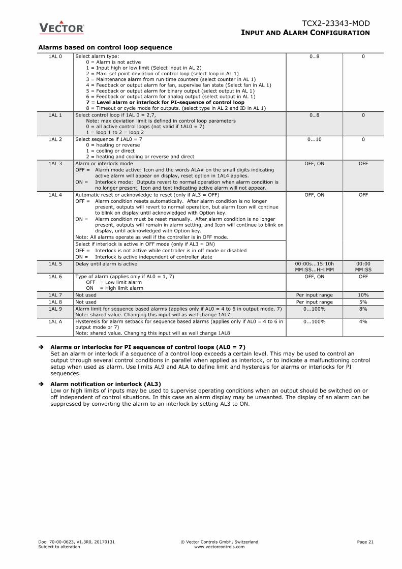
Alarms based on control loop sequence
1AL 0 Select alarm type:
0 = Alarm is not active
1 = Input high or low limit (Select input in AL 2)
2 = Max. set point deviation of control loop (select loop in AL 1)
3 = Maintenance alarm from run time counters (select counter in AL 1)
4 = Feedback or output alarm for fan, supervise fan state (Select fan in AL 1)
5 = Feedback or output alarm for binary output (select output in AL 1) 6 = Feedback or output alarm for analog output (select output in AL 1)
7 = Level alarm or interlock for PI-sequence of control loop
8 = Timeout or cycle mode for outputs. (select type in AL 2 and ID in AL 1)
0…8 0
1AL 1 Select control loop if 1AL 0 = 2,7,
Note: max deviation limit is defined in control loop parameters 0 = all active control loops (not valid if 1AL0 = 7)
1 = loop 1 to 2 = loop 2
0…8 0
1AL 2 Select sequence if 1AL0 = 7
0 = heating or reverse
1 = cooling or direct
2 = heating and cooling or reverse and direct
0...10 0
1AL 3 Alarm or interlock mode
OFF = Alarm mode active: Icon and the words ALA# on the small digits indicating
active alarm will appear on display, reset option in 1AL4 applies.
ON = Interlock mode: Outputs revert to normal operation when alarm condition is
no longer present, Icon and text indicating active alarm will not appear.
OFF, ON OFF
1AL 4 Automatic reset or acknowledge to reset (only if AL3 = OFF)
OFF = Alarm condition resets automatically. After alarm condition is no longer
present, outputs will revert to normal operation, but alarm Icon will continue
to blink on display until acknowledged with Option key.
ON = Alarm condition must be reset manually. After alarm condition is no longer
present, outputs will remain in alarm setting, and Icon will continue to blink on
display, until acknowledged with Option key.
Note: All alarms operate as well if the controller is in OFF mode.
OFF, ON OFF
Select if interlock is active in OFF mode (only if AL3 = ON)
OFF = Interlock is not active while controller is in off mode or disabled
ON = Interlock is active independent of controller state
1AL 5 Delay until alarm is active 00:00s...15:10h
MM:SS...HH:MM
00:00
MM:SS
1AL 6 Type of alarm (applies only if AL0 = 1, 7)
OFF = Low limit alarm
ON = High limit alarm
OFF, ON OFF
1AL 7 Not used Per input range 10%
1AL 8 Not used Per input range 5%
1AL 9 Alarm limit for sequence based alarms (applies only if AL0 = 4 to 6 in output mode, 7)
Note: shared value. Changing this input will as well change 1AL7
0...100% 8%
1AL A Hysteresis for alarm setback for sequence based alarms (applies only if AL0 = 4 to 6 in
output mode or 7)
Note: shared value. Changing this input will as well change 1AL8
0...100% 4%
Alarms or interlocks for PI sequences of control loops (AL0 = 7)
Set an alarm or interlock if a sequence of a control loop exceeds a certain level. This may be used to control an output through several control conditions in parallel when applied as interlock, or to indicate a malfunctioning control setup when used as alarm. Use limits AL9 and ALA to define limit and hysteresis for alarms or interlocks for PI sequences.
Alarm notification or interlock (AL3) Low or high limits of inputs may be used to supervise operating conditions when an output should be switched on or off independent of control situations. In this case an alarm display may be unwanted. The display of an alarm can be suppressed by converting the alarm to an interlock by setting AL3 to ON.

TCX2-23343-MOD
INPUT AND ALARM CONFIGURATION
Doc: 70-00-0623, V1.3R0, 20170131 © Vector Controls GmbH, Switzerland Page 22 Subject to alteration www.vectorcontrols.com
New Feature: Timeout or cycle mode for outputs
1AL 0 Select alarm type:
0 = Alarm is not active
1 = Input high or low limit (Select input in AL 2)
2 = Max. set point deviation of control loop (select loop in AL 1)
3 = Maintenance alarm from run time counters (select counter in AL 1)
4 = Feedback or output alarm for fan, supervise fan state (Select fan in AL 1)
5 = Feedback or output alarm for binary output (select output in AL 1) 6 = Feedback or output alarm for analog output (select output in AL 1)
7 = Level alarm or interlock for PI-sequence of control loop (select output in AL 1)
8 = Timeout or cycle mode for outputs.
0…8 0
1AL 1 Select fan, binary or analog output if 1AL 0 = 4, 5, 6, 8
0 = Interlock or alarm not active
1..x = selected output
0…8 0
1AL 2 Select type of device for timeout detection if 1AL0 = 8
0 = Operation mode, Active if operation mode is OFF. (revert using AL6)
1 = fan, Active if fan is off
2 = binary output
3 = analog output
0...10 0
1AL 3 Alarm or interlock mode
OFF = Alarm mode active: Icon and the words ALA# on the small digits indicating
active alarm will appear on display, reset option in 1AL4 applies.
ON = Interlock mode: Outputs revert to normal operation when alarm condition is
no longer present, Icon and text indicating active alarm will not appear.
OFF, ON OFF
1AL 4 Automatic reset or acknowledge to reset (only if AL3 = OFF)
OFF = Alarm condition resets automatically. After alarm condition is no longer
present, outputs will revert to normal operation, but alarm Icon will continue
to blink on display until acknowledged with Option key.
ON = Alarm condition must be reset manually. After alarm condition is no longer
present, outputs will remain in alarm setting, and Icon will continue to blink on
display, until acknowledged with Option key.
Note: All alarms operate as well if the controller is in OFF mode.
OFF, ON OFF
Select if interlock is active in OFF mode (only if AL3 = ON)
OFF = Interlock is not active while controller is in off mode or disabled
ON = Interlock is active independent of controller state
1AL 5 Timeout period: time while the output is off. This time will be reset if the output
activates.
00:00s...15:10h
MM:SS...HH:MM
00:00
MM:SS
1AL 6 Direct or reverse reading (applies only if AL0 = 4, 5, 6, 8)
OFF = Direct: Cycle function is active, when output is off
ON = Reverse: Cycle function is active, when output is on.
OFF, ON OFF
1AL 7 Run time in cycle mode. (applies only if AL0 = 8)
Interlock or alarm will be activated for the run time specified here.
00:00s...15:10h
MM:SS...HH:MM
00:00
1AL 8 Activation in cycle mode. (Applies only if AL0 = 8)
0 = function is active independent of operation mode
1 = function is active only in ON mode 2 = function is active only in OFF mode
3 = function is active only in disabled mode
4 = function is active only in OFF and disabled mode.
0…4 0
1AL 9 Not used 0...100% 8%
1AL A Not used 0...100% 4%
New Feature: Cycle mode for interlocks or alarms (AL0 = 8)
In cycle mode, the output will activate after a defined timeout period (AL5) for a set period of time (run time, AL7). After the run time has expired, the output will stay off for the timeout period and will activate again after it has expired and so forth.
Reverse or direct
The behavior may be reversed using AL6. If set to ON, timeout will start when the output is on and the output will deactivate during the run time defined in AL7.
The timeout period will restart, should the output activate in direct mode or deactivate in reverse mode during the defined the timeout period.
This function can be set with AL8 to be only active during certain operation modes. It can therefore be used either as valve cycle or as humidity or mould control feature. Important is to keep AL4 = ON if the function should be active in OFF or disabled mode.
Truth table for cycle activation in interlock mode (AL3 = ON)
AL4 = OFF AL4 = ON
AL8 = 0 Only active in on mode Always active
AL8 = 1 Only active in on mode Only active in on mode
AL8 = 2 Not active Only active in off mode
AL8 = 3 Not active Only active in disabled mode
AL8 = 4 Not active Only active in off or disabled mode
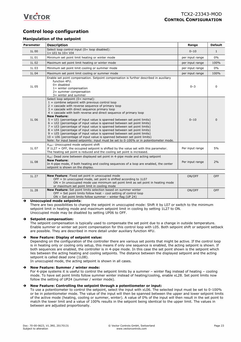
TCX2-23343-MOD
CONTROL CONFIGURATION
Doc: 70-00-0623, V1.3R0, 20170131 © Vector Controls GmbH, Switzerland Page 23
Subject to alteration www.vectorcontrols.com
Control loop configuration
Manipulation of the setpoint
Parameter Description Range Default
1L 00 Select loop control input (0= loop disabled):
1= UI1 to 10= VI4 0–10 1
1L 01 Minimum set point limit heating or winter mode per input range 0%
1L 02 Maximum set point limit heating or winter mode per input range 100%
1L 03 Minimum set point limit cooling or summer mode per input range 0%
1L 04 Maximum set point limit cooling or summer mode per input range 100%
1L 05
Enable set point compensation. Setpoint compensation is further described in auxiliary
function 4FU.
0= disabled
1= winter compensation
2= summer compensation
3= winter and summer
0–3 0
1L 06
Select loop setpoint (0= normal):
1 = combine setpoint with previous control loop
2 = cascade with reverse sequence of primary loop 3 = cascade with direct sequence primary loop
4 = cascade with both reverse and direct sequence of primary loop
New Feature:
5 = UI1 (percentage of input value is spanned between set point limits)
6 = UI2 (percentage of input value is spanned between set point limits)
7 = UI3 (percentage of input value is spanned between set point limits)
8 = UI4 (percentage of input value is spanned between set point limits)
9 = UI5 (percentage of input value is spanned between set point limits)
10 = UI6 (percentage of input value is spanned between set point limits) Note: for input based setpoints: input must be set to 0-100% or in potentiometer mode.
0–10 0
1L 07
XSBY: Unoccupied mode setpoint shift
If 1L27 = OFF, the occupied setpoint is shifted by the value set with this parameter.
The heating set point is reduced and the cooling set point is increased.
Per input range 5%
1L 08
XDZ: Dead zone between displayed set point in 4-pipe mode and acting setpoint
New Feature:
In 4-pipe mode, if both heating and cooling sequences of a loop are enabled, the center
setpoint is shown on the display.
Per input range 2%
1L 27 New Feature: Fixed set point in unoccupied mode
OFF = In unoccupied mode, set point is shifted according to 1L07 ON = In unoccupied mode use minimum set point limit as set point in heating mode
or maximum set point limit in cooling mode
ON/OFF OFF
1L 28 New Feature: Set point limits selection based on summer winter
OFF = Set point limits follow heat – cool setting of control loop
ON = Set point limits follow summer – winter flag (UP 24)
ON/OFF OFF
Unoccupied mode setpoints: There are two possibilities to change the setpoint in unoccupied mode: Shift it by L07 or switch to the minimum setpoint limit in heating mode and maximum setpoint limit in cooling by setting 1L27 to ON. Unoccupied mode may be disabled by setting UP06 to OFF.
Setpoint compensation:
The setpoint compensation is typically used to compensate the set point due to a change in outside temperature. Enable summer or winter set point compensation for this control loop with L05. Both setpoint shift or setpoint setback are possible. They are described in more detail under auxiliary function 4FU.
New Feature: Display of setpoint value: Depending on the configuration of the controller there are various set points that might be active. If the control loop is in heating only or cooling only setup, this means if only one sequence is enabled, the acting setpoint is shown. If both sequences are enabled, the controller is in 4-pipe mode. In this case the set point shown is the setpoint which lies between the acting heating and cooling setpoints. The distance between the displayed setpoint and the acting setpoint is called dead zone (1L08). In unoccupied mode, the acting setpoint is shown in all cases.
New Feature: Summer / winter mode: For 4-pipe systems it is useful to control the setpoint limits by a summer – winter flag instead of heating – cooling mode. To have set point limits follow summer winter instead of heating/cooling, enable xL28. Set point limits now follow the setting of UP24 (summer / winter mode).
New Feature: Controlling the setpoint through a potentiometer or input: To use a potentiometer to control the setpoint, select the input with xL06. The selected input must be set to 0-100% or be in potentiometer mode. The value of the input will then be spanned between the upper and lower setpoint limits of the active mode (heating, cooling or summer, winter). A value of 0% of the input will then result in the set point to match the lower limit and a value of 100% results in the setpoint being identical to the upper limit. The values in between are adjusted proportionally.
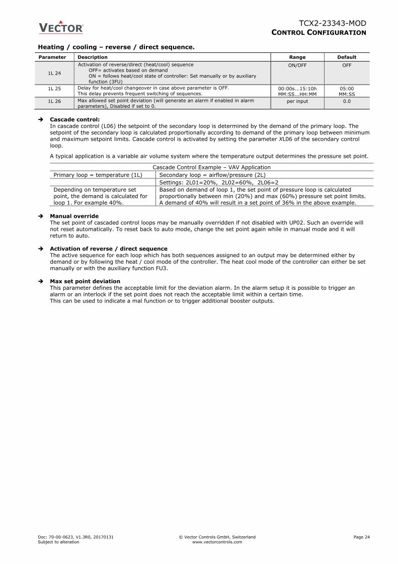
TCX2-23343-MOD
CONTROL CONFIGURATION
Doc: 70-00-0623, V1.3R0, 20170131 © Vector Controls GmbH, Switzerland Page 24
Subject to alteration www.vectorcontrols.com
Heating / cooling – reverse / direct sequence.
Parameter Description Range Default
1L 24
Activation of reverse/direct (heat/cool) sequence
OFF= activates based on demand
ON = follows heat/cool state of controller: Set manually or by auxiliary
function (3FU)
ON/OFF OFF
1L 25 Delay for heat/cool changeover in case above parameter is OFF.
This delay prevents frequent switching of sequences. 00:00s...15:10h MM:SS...HH:MM
05:00 MM:SS
1L 26 Max allowed set point deviation (will generate an alarm if enabled in alarm parameters), Disabled if set to 0.
per input 0.0
Cascade control:
In cascade control (L06) the setpoint of the secondary loop is determined by the demand of the primary loop. The setpoint of the secondary loop is calculated proportionally according to demand of the primary loop between minimum and maximum setpoint limits. Cascade control is activated by setting the parameter XL06 of the secondary control loop.
A typical application is a variable air volume system where the temperature output determines the pressure set point.
Cascade Control Example – VAV Application
Primary loop = temperature (1L) Secondary loop = airflow/pressure (2L)
Settings: 2L01=20%, 2L02=60%, 2L06=2
Depending on temperature set point, the demand is calculated for loop 1. For example 40%.
Based on demand of loop 1, the set point of pressure loop is calculated proportionally between min (20%) and max (60%) pressure set point limits. A demand of 40% will result in a set point of 36% in the above example.
Manual override
The set point of cascaded control loops may be manually overridden if not disabled with UP02. Such an override will not reset automatically. To reset back to auto mode, change the set point again while in manual mode and it will return to auto.
Activation of reverse / direct sequence The active sequence for each loop which has both sequences assigned to an output may be determined either by demand or by following the heat / cool mode of the controller. The heat cool mode of the controller can either be set manually or with the auxiliary function FU3.
Max set point deviation
This parameter defines the acceptable limit for the deviation alarm. In the alarm setup it is possible to trigger an alarm or an interlock if the set point does not reach the acceptable limit within a certain time. This can be used to indicate a mal function or to trigger additional booster outputs.
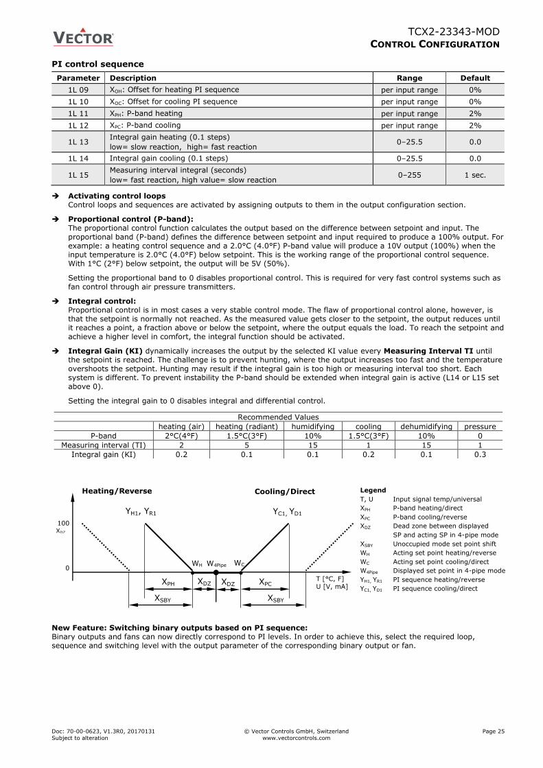
TCX2-23343-MOD
CONTROL CONFIGURATION
Doc: 70-00-0623, V1.3R0, 20170131 © Vector Controls GmbH, Switzerland Page 25
Subject to alteration www.vectorcontrols.com
PI control sequence
Parameter Description Range Default
1L 09 XOH: Offset for heating PI sequence per input range 0%
1L 10 XOC: Offset for cooling PI sequence per input range 0%
1L 11 XPH: P-band heating per input range 2%
1L 12 XPC: P-band cooling per input range 2%
1L 13 Integral gain heating (0.1 steps)
low= slow reaction, high= fast reaction 0–25.5 0.0
1L 14 Integral gain cooling (0.1 steps) 0–25.5 0.0
1L 15 Measuring interval integral (seconds)
low= fast reaction, high value= slow reaction 0–255 1 sec.
Activating control loops Control loops and sequences are activated by assigning outputs to them in the output configuration section.
Proportional control (P-band): The proportional control function calculates the output based on the difference between setpoint and input. The proportional band (P-band) defines the difference between setpoint and input required to produce a 100% output. For example: a heating control sequence and a 2.0°C (4.0°F) P-band value will produce a 10V output (100%) when the input temperature is 2.0°C (4.0°F) below setpoint. This is the working range of the proportional control sequence. With 1°C (2°F) below setpoint, the output will be 5V (50%).
Setting the proportional band to 0 disables proportional control. This is required for very fast control systems such as fan control through air pressure transmitters.
Integral control: Proportional control is in most cases a very stable control mode. The flaw of proportional control alone, however, is that the setpoint is normally not reached. As the measured value gets closer to the setpoint, the output reduces until it reaches a point, a fraction above or below the setpoint, where the output equals the load. To reach the setpoint and achieve a higher level in comfort, the integral function should be activated.
Integral Gain (KI) dynamically increases the output by the selected KI value every Measuring Interval TI until the setpoint is reached. The challenge is to prevent hunting, where the output increases too fast and the temperature overshoots the setpoint. Hunting may result if the integral gain is too high or measuring interval too short. Each system is different. To prevent instability the P-band should be extended when integral gain is active (L14 or L15 set above 0).
Setting the integral gain to 0 disables integral and differential control.
New Feature: Switching binary outputs based on PI sequence: Binary outputs and fans can now directly correspond to PI levels. In order to achieve this, select the required loop, sequence and switching level with the output parameter of the corresponding binary output or fan.
Recommended Values
heating (air) heating (radiant) humidifying cooling dehumidifying pressure
P-band 2°C(4°F) 1.5°C(3°F) 10% 1.5°C(3°F) 10% 0
Measuring interval (TI) 2 5 15 1 15 1
Integral gain (KI) 0.2 0.1 0.1 0.2 0.1 0.3
100 XDZ
0
Heating/Reverse Cooling/Direct
T [°C, F]
U [V, mA]
YH1, YR1
XPH
WH
XPC XDZ
YC1, YD1
WC
XSBY XSBY
W4Pipe
XDZ
Legend
T, U Input signal temp/universal
XPH P-band heating/direct
XPC P-band cooling/reverse
XDZ Dead zone between displayed
SP and acting SP in 4-pipe mode
XSBY Unoccupied mode set point shift
WH Acting set point heating/reverse
WC Acting set point cooling/direct
W4Pipe Displayed set point in 4-pipe mode
YH1, YR1 PI sequence heating/reverse
YC1, YD1 PI sequence cooling/direct
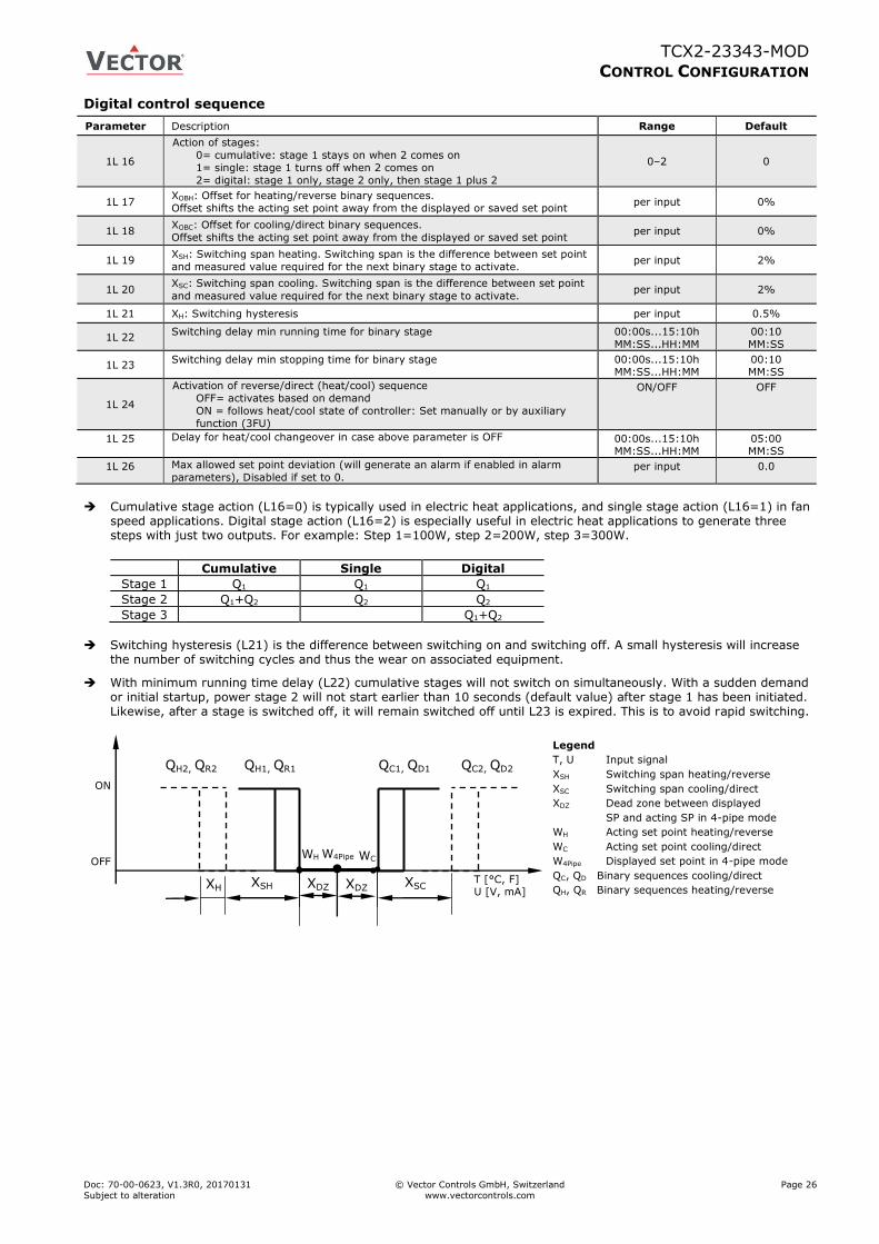
TCX2-23343-MOD
CONTROL CONFIGURATION
Doc: 70-00-0623, V1.3R0, 20170131 © Vector Controls GmbH, Switzerland Page 26
Subject to alteration www.vectorcontrols.com
Digital control sequence
Parameter Description Range Default
1L 16
Action of stages:
0= cumulative: stage 1 stays on when 2 comes on
1= single: stage 1 turns off when 2 comes on
2= digital: stage 1 only, stage 2 only, then stage 1 plus 2
0–2 0
1L 17 XOBH: Offset for heating/reverse binary sequences.
Offset shifts the acting set point away from the displayed or saved set point per input 0%
1L 18 XOBC: Offset for cooling/direct binary sequences.
Offset shifts the acting set point away from the displayed or saved set point per input 0%
1L 19 XSH: Switching span heating. Switching span is the difference between set point
and measured value required for the next binary stage to activate. per input 2%
1L 20 XSC: Switching span cooling. Switching span is the difference between set point
and measured value required for the next binary stage to activate. per input 2%
1L 21 XH: Switching hysteresis per input 0.5%
1L 22 Switching delay min running time for binary stage 00:00s...15:10h
MM:SS...HH:MM
00:10
MM:SS
1L 23 Switching delay min stopping time for binary stage 00:00s...15:10h
MM:SS...HH:MM 00:10 MM:SS
1L 24
Activation of reverse/direct (heat/cool) sequence
OFF= activates based on demand
ON = follows heat/cool state of controller: Set manually or by auxiliary
function (3FU)
ON/OFF OFF
1L 25 Delay for heat/cool changeover in case above parameter is OFF 00:00s...15:10h MM:SS...HH:MM
05:00 MM:SS
1L 26 Max allowed set point deviation (will generate an alarm if enabled in alarm
parameters), Disabled if set to 0. per input 0.0
Cumulative stage action (L16=0) is typically used in electric heat applications, and single stage action (L16=1) in fan
speed applications. Digital stage action (L16=2) is especially useful in electric heat applications to generate three steps with just two outputs. For example: Step 1=100W, step 2=200W, step 3=300W.
Switching hysteresis (L21) is the difference between switching on and switching off. A small hysteresis will increase the number of switching cycles and thus the wear on associated equipment.
With minimum running time delay (L22) cumulative stages will not switch on simultaneously. With a sudden demand or initial startup, power stage 2 will not start earlier than 10 seconds (default value) after stage 1 has been initiated. Likewise, after a stage is switched off, it will remain switched off until L23 is expired. This is to avoid rapid switching.
Cumulative Single Digital
Stage 1 Q1 Q1 Q1
Stage 2 Q1+Q2 Q2 Q2
Stage 3 Q1+Q2
ON
OFF
T [°C, F] U [V, mA]
QC2, QD2
XSH XSC XH
QC1, QD1 QH2, QR2 QH1, QR1
WH
XDZ
WC W4Pipe
XDZ
Legend
T, U Input signal
XSH Switching span heating/reverse
XSC Switching span cooling/direct
XDZ Dead zone between displayed
SP and acting SP in 4-pipe mode
WH Acting set point heating/reverse
WC Acting set point cooling/direct
W4Pipe Displayed set point in 4-pipe mode
QC, QD Binary sequences cooling/direct
QH, QR Binary sequences heating/reverse
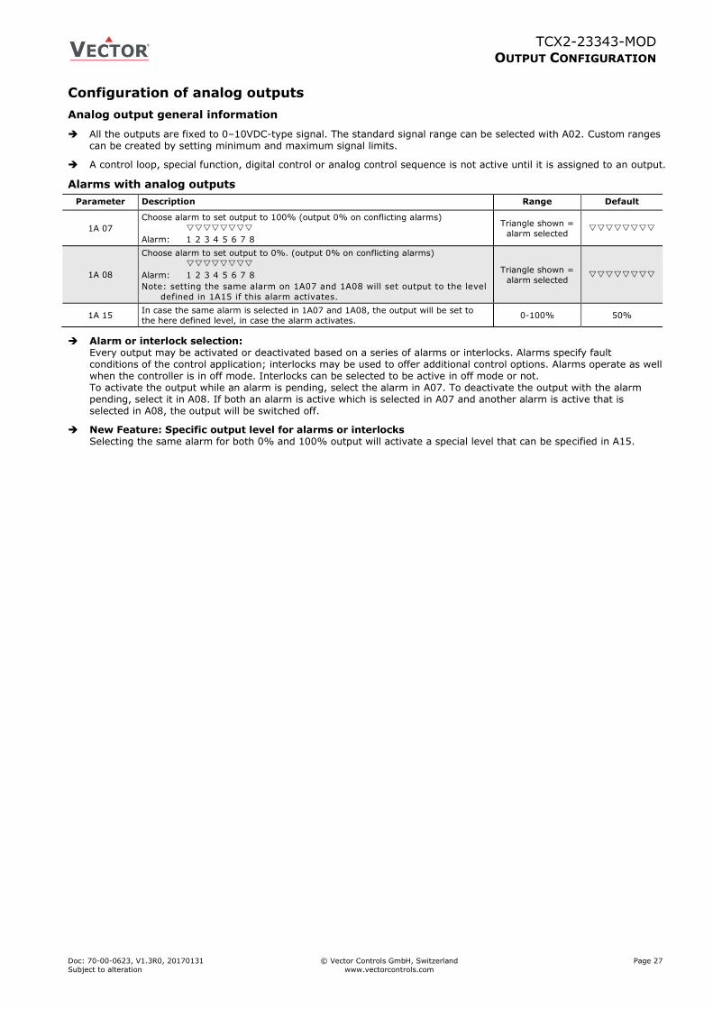
TCX2-23343-MOD
OUTPUT CONFIGURATION
Doc: 70-00-0623, V1.3R0, 20170131 © Vector Controls GmbH, Switzerland Page 27
Subject to alteration www.vectorcontrols.com
Configuration of analog outputs
Analog output general information
All the outputs are fixed to 0–10VDC-type signal. The standard signal range can be selected with A02. Custom ranges can be created by setting minimum and maximum signal limits.
A control loop, special function, digital control or analog control sequence is not active until it is assigned to an output.
Alarms with analog outputs
Parameter Description Range Default
1A 07
Choose alarm to set output to 100% (output 0% on conflicting alarms)
Alarm: 1 2 3 4 5 6 7 8
Triangle shown =
alarm selected
1A 08
Choose alarm to set output to 0%. (output 0% on conflicting alarms)
Alarm: 1 2 3 4 5 6 7 8
Note: setting the same alarm on 1A07 and 1A08 will set output to the level
defined in 1A15 if this alarm activates.
Triangle shown =
alarm selected
1A 15 In case the same alarm is selected in 1A07 and 1A08, the output will be set to
the here defined level, in case the alarm activates. 0-100% 50%
Alarm or interlock selection: Every output may be activated or deactivated based on a series of alarms or interlocks. Alarms specify fault conditions of the control application; interlocks may be used to offer additional control options. Alarms operate as well when the controller is in off mode. Interlocks can be selected to be active in off mode or not. To activate the output while an alarm is pending, select the alarm in A07. To deactivate the output with the alarm pending, select it in A08. If both an alarm is active which is selected in A07 and another alarm is active that is selected in A08, the output will be switched off.
New Feature: Specific output level for alarms or interlocks Selecting the same alarm for both 0% and 100% output will activate a special level that can be specified in A15.
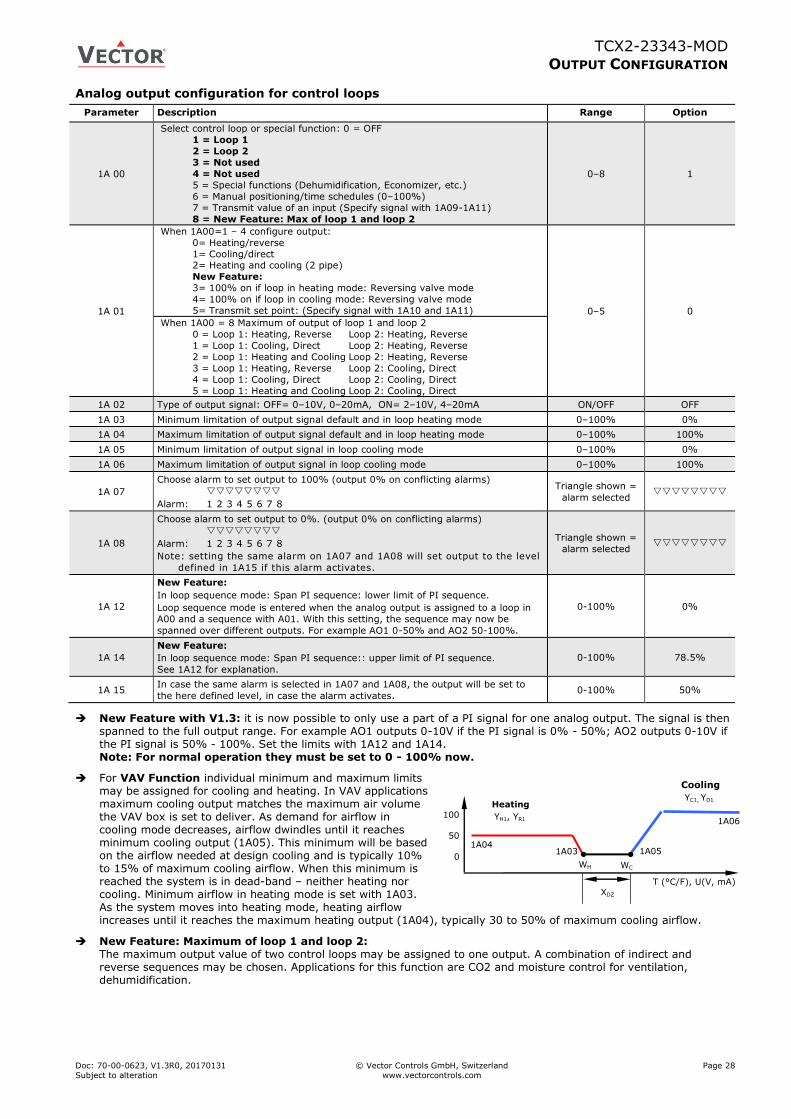
TCX2-23343-MOD
OUTPUT CONFIGURATION
Doc: 70-00-0623, V1.3R0, 20170131 © Vector Controls GmbH, Switzerland Page 28
Subject to alteration www.vectorcontrols.com
WH WC
100
50
0
YH1, YR1
XDZ
YC1, YD1 Heating
Cooling
1A04 1A05 1A03
1A06
T (°C/F), U(V, mA)
Analog output configuration for control loops
Parameter Description Range Option
1A 00
Select control loop or special function: 0 = OFF
1 = Loop 1
2 = Loop 2
3 = Not used
4 = Not used
5 = Special functions (Dehumidification, Economizer, etc.)
6 = Manual positioning/time schedules (0–100%)
7 = Transmit value of an input (Specify signal with 1A09-1A11)
8 = New Feature: Max of loop 1 and loop 2
0–8 1
1A 01
When 1A00=1 – 4 configure output:
0= Heating/reverse
1= Cooling/direct
2= Heating and cooling (2 pipe)
New Feature:
3= 100% on if loop in heating mode: Reversing valve mode
4= 100% on if loop in cooling mode: Reversing valve mode
5= Transmit set point: (Specify signal with 1A10 and 1A11) 0–5 0
When 1A00 = 8 Maximum of output of loop 1 and loop 2
0 = Loop 1: Heating, Reverse Loop 2: Heating, Reverse
1 = Loop 1: Cooling, Direct Loop 2: Heating, Reverse
2 = Loop 1: Heating and Cooling Loop 2: Heating, Reverse
3 = Loop 1: Heating, Reverse Loop 2: Cooling, Direct
4 = Loop 1: Cooling, Direct Loop 2: Cooling, Direct
5 = Loop 1: Heating and Cooling Loop 2: Cooling, Direct
1A 02 Type of output signal: OFF= 0–10V, 0–20mA, ON= 2–10V, 4–20mA ON/OFF OFF
1A 03 Minimum limitation of output signal default and in loop heating mode 0–100% 0%
1A 04 Maximum limitation of output signal default and in loop heating mode 0–100% 100%
1A 05 Minimum limitation of output signal in loop cooling mode 0–100% 0%
1A 06 Maximum limitation of output signal in loop cooling mode 0–100% 100%
1A 07
Choose alarm to set output to 100% (output 0% on conflicting alarms)
Alarm: 1 2 3 4 5 6 7 8
Triangle shown =
alarm selected
1A 08
Choose alarm to set output to 0%. (output 0% on conflicting alarms)
Alarm: 1 2 3 4 5 6 7 8
Note: setting the same alarm on 1A07 and 1A08 will set output to the level
defined in 1A15 if this alarm activates.
Triangle shown =
alarm selected
1A 12
New Feature:
In loop sequence mode: Span PI sequence: lower limit of PI sequence.
Loop sequence mode is entered when the analog output is assigned to a loop in
A00 and a sequence with A01. With this setting, the sequence may now be
spanned over different outputs. For example AO1 0-50% and AO2 50-100%.
0-100% 0%
1A 14
New Feature:
In loop sequence mode: Span PI sequence:: upper limit of PI sequence.
See 1A12 for explanation.
0-100% 78.5%
1A 15 In case the same alarm is selected in 1A07 and 1A08, the output will be set to
the here defined level, in case the alarm activates. 0-100% 50%
New Feature with V1.3: it is now possible to only use a part of a PI signal for one analog output. The signal is then spanned to the full output range. For example AO1 outputs 0-10V if the PI signal is 0% - 50%; AO2 outputs 0-10V if the PI signal is 50% - 100%. Set the limits with 1A12 and 1A14. Note: For normal operation they must be set to 0 - 100% now.
For VAV Function individual minimum and maximum limits may be assigned for cooling and heating. In VAV applications maximum cooling output matches the maximum air volume the VAV box is set to deliver. As demand for airflow in cooling mode decreases, airflow dwindles until it reaches minimum cooling output (1A05). This minimum will be based on the airflow needed at design cooling and is typically 10% to 15% of maximum cooling airflow. When this minimum is reached the system is in dead-band – neither heating nor cooling. Minimum airflow in heating mode is set with 1A03. As the system moves into heating mode, heating airflow increases until it reaches the maximum heating output (1A04), typically 30 to 50% of maximum cooling airflow.
New Feature: Maximum of loop 1 and loop 2: The maximum output value of two control loops may be assigned to one output. A combination of indirect and reverse sequences may be chosen. Applications for this function are CO2 and moisture control for ventilation, dehumidification.
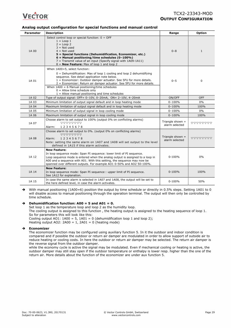
TCX2-23343-MOD
OUTPUT CONFIGURATION
Doc: 70-00-0623, V1.3R0, 20170131 © Vector Controls GmbH, Switzerland Page 29
Subject to alteration www.vectorcontrols.com
Analog output configuration for special functions and manual control
Parameter Description Range Option
1A 00
Select control loop or special function: 0 = OFF
1 = Loop 1
2 = Loop 2
3 = Not used
4 = Not used
5 = Special functions (Dehumidification, Economizer, etc.)
6 = Manual positioning/time schedules (0–100%)
7 = Transmit value of an input (Specify signal with 1A09-1A11)
8 = New Feature: Max of loop 1 and loop 2
0–8 1
1A 01
When 1A00=5, select function:
0 = Dehumidification: Max of loop 1 cooling and loop 2 dehumidifying
sequence. See detail application note below. 1 = Economizer: Outdoor damper actuator. See 5FU for more details.
2 = Economizer: Return air damper actuator. See 5FU for more details. 0–5 0
When 1A00 = 6 Manual positioning/time schedules 0 = Allow time schedule only
1 = Allow manual positioning and time schedules
1A 02 Type of output signal: OFF= 0–10V, 0–20mA, ON= 2–10V, 4–20mA ON/OFF OFF
1A 03 Minimum limitation of output signal default and in loop heating mode 0–100% 0%
1A 04 Maximum limitation of output signal default and in loop heating mode 0–100% 100%
1A 05 Minimum limitation of output signal in loop cooling mode 0–100% 0%
1A 06 Maximum limitation of output signal in loop cooling mode 0–100% 100%
1A 07
Choose alarm to set output to 100% (output 0% on conflicting alarms)
Alarm: 1 2 3 4 5 6 7 8
Triangle shown =
alarm selected
1A 08
Choose alarm to set output to 0%. (output 0% on conflicting alarms)
Alarm: 1 2 3 4 5 6 7 8
Note: setting the same alarm on 1A07 and 1A08 will set output to the level
defined in 1A15 if this alarm activates.
Triangle shown =
alarm selected
1A 12
New Feature:
In loop sequence mode: Span PI sequence: lower limit of PI sequence.
Loop sequence mode is entered when the analog output is assigned to a loop in
A00 and a sequence with A01. With this setting, the sequence may now be
spanned over different outputs. For example AO1 0-50% and AO2 50-100%.
0-100% 0%
1A 14
New Feature:
In loop sequence mode: Span PI sequence:: upper limit of PI sequence.
See 1A12 for explanation.
0-100% 100%
1A 15 In case the same alarm is selected in 1A07 and 1A08, the output will be set to
the here defined level, in case the alarm activates. 0-100% 50%
With manual positioning (1A00=6) position the output by time schedule or directly in 0.5% steps. Setting 1A01 to 0 will disable access to manual positioning through the operation terminal. The output will then only be controlled by time schedule.
Dehumidification function: A00 = 5 and A01 = 0. Set loop 1 as the temperature loop and loop 2 as the humidity loop. The cooling output is assigned to this function , the heating output is assigned to the heating sequence of loop 1. So for parameters this will look like this: Cooling output AO1: 1A00 = 5, 1A01 = 0 (dehumidification loop 1 and loop 2); Heating output AO2: 2A00 = 1, 2A01 = 0 (heating mode)
Economizer The economizer function may be configured using auxiliary function 5. In it the outdoor and indoor condition is compared and if possible the outdoor or return air damper are modulated in order to allow support of outside air to reduce heating or cooling costs. In here the outdoor or return air damper may be selected. The return air damper is the reverse signal from the outdoor damper. while the economy cycle is active the signal may be modulated. Even if mechanical cooling or heating is active, the outdoor damper may still stay open if the outdoor temperature or enthalpy is lower resp. higher than the one of the return air. More details about the function of the economizer are under aux function 5.
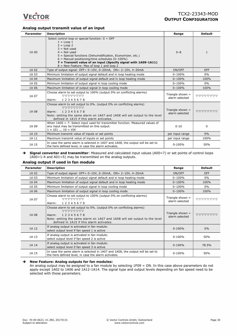
TCX2-23343-MOD
OUTPUT CONFIGURATION
Doc: 70-00-0623, V1.3R0, 20170131 © Vector Controls GmbH, Switzerland Page 30
Subject to alteration www.vectorcontrols.com
Analog output transmit value of an input
Parameter Description Range Default
1A 00
Select control loop or special function: 0 = OFF
1 = Loop 1
2 = Loop 2
3 = Not used
4 = Not used
5 = Special functions (Dehumidification, Economizer, etc.)
6 = Manual positioning/time schedules (0–100%)
7 = Transmit value of an input (Specify signal with 1A09-1A11)
8 = New Feature: Max of loop 1 and loop 2
0–8 1
1A 02 Type of output signal: OFF= 0–10V, 0–20mA, ON= 2–10V, 4–20mA ON/OFF OFF
1A 03 Minimum limitation of output signal default and in loop heating mode 0–100% 0%
1A 04 Maximum limitation of output signal default and in loop heating mode 0–100% 100%
1A 05 Minimum limitation of output signal in loop cooling mode 0–100% 0%
1A 06 Maximum limitation of output signal in loop cooling mode 0–100% 100%
1A 07
Choose alarm to set output to 100% (output 0% on conflicting alarms)
Alarm: 1 2 3 4 5 6 7 8
Triangle shown =
alarm selected
1A 08
Choose alarm to set output to 0%. (output 0% on conflicting alarms)
Alarm: 1 2 3 4 5 6 7 8
Note: setting the same alarm on 1A07 and 1A08 will set output to the level
defined in 1A15 if this alarm activates.
Triangle shown =
alarm selected
1A 09
When 1A00 = 7: Select input used for transmitter function. Measured values of any input may be transmitted on this output.
1 = UI1 ... 10 = VI4 0-10 0
1A 10 Minimum transmit value of inputs or set points per input range 0%
1A 11 Maximum transmit value of inputs or set points per input range 100%
1A 15 In case the same alarm is selected in 1A07 and 1A08, the output will be set to
the here defined level, in case the alarm activates. 0-100% 50%
Signal converter and transmitter: Measured and calculated input values (A00=7) or set points of control loops (A00=1-4 and A01=5) may be transmitted on the analog outputs.
Analog output if used in fan module
Parameter Description Range Default
1A 02 Type of output signal: OFF= 0–10V, 0–20mA, ON= 2–10V, 4–20mA ON/OFF OFF
1A 03 Minimum limitation of output signal default and in loop heating mode 0–100% 0%
1A 04 Maximum limitation of output signal default and in loop heating mode 0–100% 100%
1A 05 Minimum limitation of output signal in loop cooling mode 0–100% 0%
1A 06 Maximum limitation of output signal in loop cooling mode 0–100% 100%
1A 07
Choose alarm to set output to 100% (output 0% on conflicting alarms)
Alarm: 1 2 3 4 5 6 7 8
Triangle shown =
alarm selected
1A 08
Choose alarm to set output to 0%. (output 0% on conflicting alarms)
Alarm: 1 2 3 4 5 6 7 8
Note: setting the same alarm on 1A07 and 1A08 will set output to the level
defined in 1A15 if this alarm activates.
Triangle shown =
alarm selected
1A 12 If analog output is activated in fan module:
select output level if fan speed 1 is active 0-100% 0%
1A 13 If analog output is activated in fan module:
select output level if fan speed 2 is active 0-100% 50%
1A 14 If analog output is activated in fan module:
select output level if fan speed 3 is active 0-100% 78.5%
1A 15 In case the same alarm is selected in 1A07 and 1A08, the output will be set to
the here defined level, in case the alarm activates. 0-100% 50%
New Feature: Analog outputs for fan modules: An analog output may be assigned to a fan module by selecting 1F09 = ON. In this case above parameters do not apply except 1A02 to 1A06 and 1A12-1A14. The signal type and output levels depending on fan speed need to be selected with those parameters.
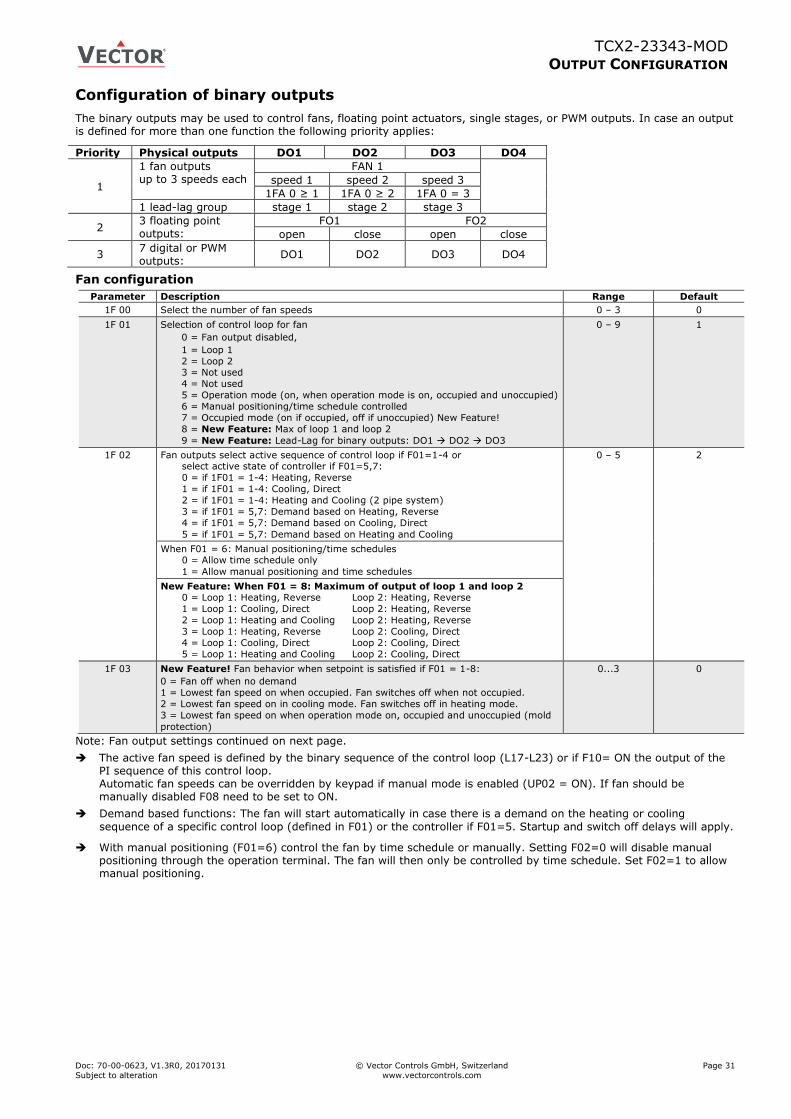
TCX2-23343-MOD
OUTPUT CONFIGURATION
Doc: 70-00-0623, V1.3R0, 20170131 © Vector Controls GmbH, Switzerland Page 31
Subject to alteration www.vectorcontrols.com
Configuration of binary outputs
The binary outputs may be used to control fans, floating point actuators, single stages, or PWM outputs. In case an output is defined for more than one function the following priority applies:
Priority Physical outputs DO1 DO2 DO3 DO4
1
1 fan outputs up to 3 speeds each
FAN 1
speed 1 speed 2 speed 3
1FA 0 ≥ 1 1FA 0 ≥ 2 1FA 0 = 3
1 lead-lag group stage 1 stage 2 stage 3
2 3 floating point outputs:
FO1 FO2
open close open close
3 7 digital or PWM outputs:
DO1 DO2 DO3 DO4
Fan configuration
Parameter Description Range Default
1F 00 Select the number of fan speeds 0 – 3 0
1F 01 Selection of control loop for fan
0 = Fan output disabled,
1 = Loop 1
2 = Loop 2 3 = Not used
4 = Not used
5 = Operation mode (on, when operation mode is on, occupied and unoccupied)
6 = Manual positioning/time schedule controlled
7 = Occupied mode (on if occupied, off if unoccupied) New Feature!
8 = New Feature: Max of loop 1 and loop 2
9 = New Feature: Lead-Lag for binary outputs: DO1 DO2 DO3
0 – 9 1
1F 02 Fan outputs select active sequence of control loop if F01=1-4 or select active state of controller if F01=5,7:
0 = if 1F01 = 1-4: Heating, Reverse
1 = if 1F01 = 1-4: Cooling, Direct
2 = if 1F01 = 1-4: Heating and Cooling (2 pipe system)
3 = if 1F01 = 5,7: Demand based on Heating, Reverse
4 = if 1F01 = 5,7: Demand based on Cooling, Direct
5 = if 1F01 = 5,7: Demand based on Heating and Cooling
0 – 5 2
When F01 = 6: Manual positioning/time schedules 0 = Allow time schedule only
1 = Allow manual positioning and time schedules
New Feature: When F01 = 8: Maximum of output of loop 1 and loop 2 0 = Loop 1: Heating, Reverse Loop 2: Heating, Reverse
1 = Loop 1: Cooling, Direct Loop 2: Heating, Reverse
2 = Loop 1: Heating and Cooling Loop 2: Heating, Reverse
3 = Loop 1: Heating, Reverse Loop 2: Cooling, Direct
4 = Loop 1: Cooling, Direct Loop 2: Cooling, Direct
5 = Loop 1: Heating and Cooling Loop 2: Cooling, Direct
1F 03 New Feature! Fan behavior when setpoint is satisfied if F01 = 1-8:
0 = Fan off when no demand
1 = Lowest fan speed on when occupied. Fan switches off when not occupied.
2 = Lowest fan speed on in cooling mode. Fan switches off in heating mode.
3 = Lowest fan speed on when operation mode on, occupied and unoccupied (mold
protection)
0...3 0
Note: Fan output settings continued on next page.
The active fan speed is defined by the binary sequence of the control loop (L17-L23) or if F10= ON the output of the PI sequence of this control loop. Automatic fan speeds can be overridden by keypad if manual mode is enabled (UP02 = ON). If fan should be manually disabled F08 need to be set to ON.
Demand based functions: The fan will start automatically in case there is a demand on the heating or cooling
sequence of a specific control loop (defined in F01) or the controller if F01=5. Startup and switch off delays will apply.
With manual positioning (F01=6) control the fan by time schedule or manually. Setting F02=0 will disable manual positioning through the operation terminal. The fan will then only be controlled by time schedule. Set F02=1 to allow manual positioning.
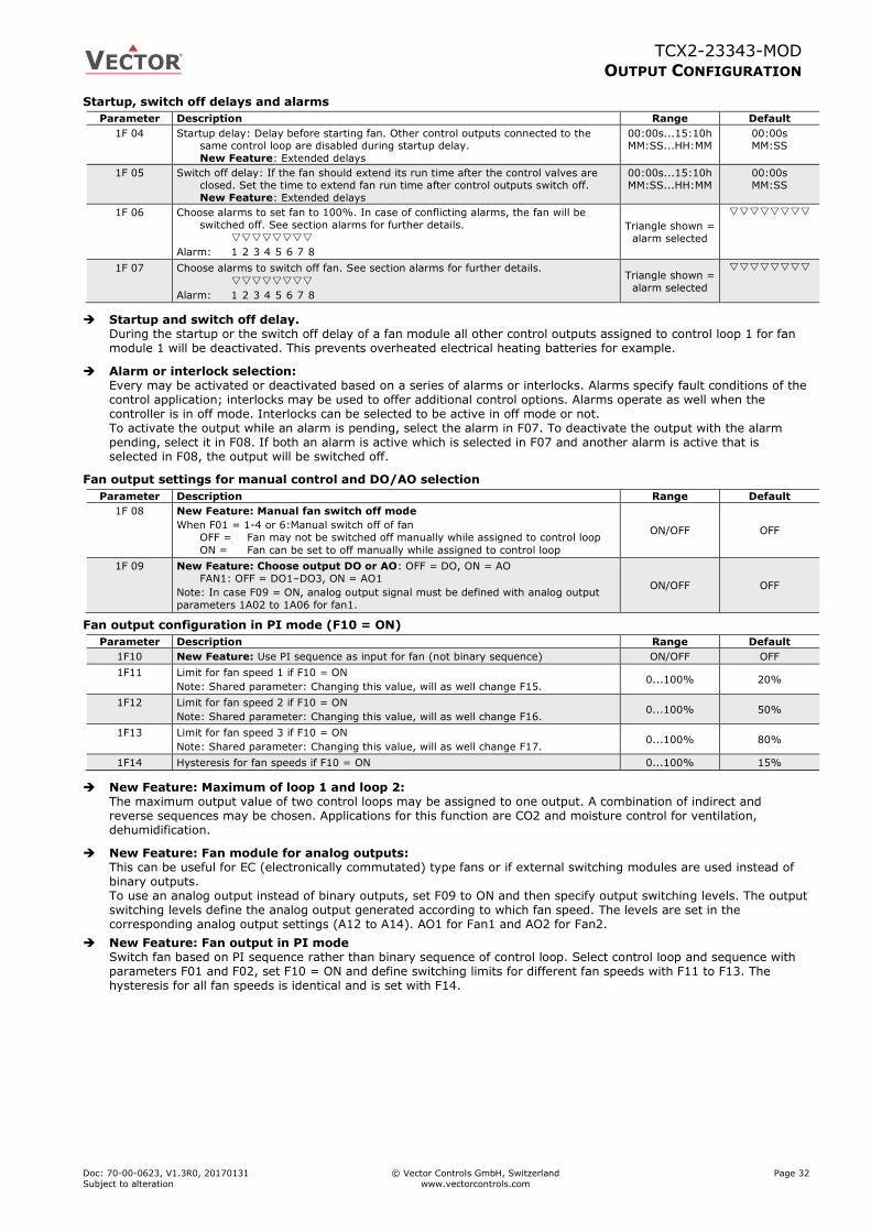
TCX2-23343-MOD
OUTPUT CONFIGURATION
Doc: 70-00-0623, V1.3R0, 20170131 © Vector Controls GmbH, Switzerland Page 32
Subject to alteration www.vectorcontrols.com
Startup, switch off delays and alarms
Parameter Description Range Default
1F 04 Startup delay: Delay before starting fan. Other control outputs connected to the same control loop are disabled during startup delay.
New Feature: Extended delays
00:00s...15:10h MM:SS...HH:MM
00:00s MM:SS
1F 05 Switch off delay: If the fan should extend its run time after the control valves are closed. Set the time to extend fan run time after control outputs switch off.
New Feature: Extended delays
00:00s...15:10h MM:SS...HH:MM
00:00s MM:SS
1F 06 Choose alarms to set fan to 100%. In case of conflicting alarms, the fan will be
switched off. See section alarms for further details.
Alarm: 1 2 3 4 5 6 7 8
Triangle shown =
alarm selected
1F 07 Choose alarms to switch off fan. See section alarms for further details.
Alarm: 1 2 3 4 5 6 7 8
Triangle shown =
alarm selected
Startup and switch off delay. During the startup or the switch off delay of a fan module all other control outputs assigned to control loop 1 for fan module 1 will be deactivated. This prevents overheated electrical heating batteries for example.
Alarm or interlock selection: Every may be activated or deactivated based on a series of alarms or interlocks. Alarms specify fault conditions of the control application; interlocks may be used to offer additional control options. Alarms operate as well when the controller is in off mode. Interlocks can be selected to be active in off mode or not. To activate the output while an alarm is pending, select the alarm in F07. To deactivate the output with the alarm pending, select it in F08. If both an alarm is active which is selected in F07 and another alarm is active that is selected in F08, the output will be switched off.
Fan output settings for manual control and DO/AO selection
Parameter Description Range Default
1F 08 New Feature: Manual fan switch off mode
When F01 = 1-4 or 6:Manual switch off of fan
OFF = Fan may not be switched off manually while assigned to control loop
ON = Fan can be set to off manually while assigned to control loop
ON/OFF OFF
1F 09 New Feature: Choose output DO or AO: OFF = DO, ON = AO
FAN1: OFF = DO1–DO3, ON = AO1
Note: In case F09 = ON, analog output signal must be defined with analog output
parameters 1A02 to 1A06 for fan1.
ON/OFF OFF
Fan output configuration in PI mode (F10 = ON)
Parameter Description Range Default
1F10 New Feature: Use PI sequence as input for fan (not binary sequence) ON/OFF OFF
1F11 Limit for fan speed 1 if F10 = ON
Note: Shared parameter: Changing this value, will as well change F15. 0...100% 20%
1F12 Limit for fan speed 2 if F10 = ON
Note: Shared parameter: Changing this value, will as well change F16. 0...100% 50%
1F13 Limit for fan speed 3 if F10 = ON
Note: Shared parameter: Changing this value, will as well change F17. 0...100% 80%
1F14 Hysteresis for fan speeds if F10 = ON 0...100% 15%
New Feature: Maximum of loop 1 and loop 2: The maximum output value of two control loops may be assigned to one output. A combination of indirect and reverse sequences may be chosen. Applications for this function are CO2 and moisture control for ventilation, dehumidification.
New Feature: Fan module for analog outputs: This can be useful for EC (electronically commutated) type fans or if external switching modules are used instead of binary outputs. To use an analog output instead of binary outputs, set F09 to ON and then specify output switching levels. The output switching levels define the analog output generated according to which fan speed. The levels are set in the corresponding analog output settings (A12 to A14). AO1 for Fan1 and AO2 for Fan2.
New Feature: Fan output in PI mode Switch fan based on PI sequence rather than binary sequence of control loop. Select control loop and sequence with parameters F01 and F02, set F10 = ON and define switching limits for different fan speeds with F11 to F13. The hysteresis for all fan speeds is identical and is set with F14.

TCX2-23343-MOD
OUTPUT CONFIGURATION
Doc: 70-00-0623, V1.3R0, 20170131 © Vector Controls GmbH, Switzerland Page 33
Subject to alteration www.vectorcontrols.com
Lead-lag configuration
Parameter Description Range Default
1F 00 Total number of lead/lag stages 0 – 3 0
1F 01 Selection of control loop for fan
9 = New Feature: Lead-lag configuration: OUT1 OUT2 OUT3
0 – 9 1
1F 02 In lead-lag mode:
Define number of simultaneous active outputs. If set to 0 or 1, then only one
output will be active at the same time, if set to 2 than 2 outputs will be active
at each time. For this to work at least 3 outputs must be activated.
0 – 5 2
1F 03 In lead-lag mode (F01 = 9): Step length of F15
0 = Steps defined in F15 are counted in minutes
1 = Steps defined in F15 are counted in hours
2 = Steps defined in F15 are counted in days (24h)
0...3 0
1F 04 Startup delay: Delay before starting new stage. Other outputs assigned to same control loop are disabled during delay.
New Feature: Extended delays
00:00s...15:10h MM:SS...HH:MM
00:00s MM:SS
1F 05 Switch off delay: Delay while switching off old stage. Other outputs assigned to
same control loop are disabled during delay.
New Feature: Extended delays
00:00s...15:10h
MM:SS...HH:MM
00:00s
MM:SS
1F 06 Choose alarms to activate all assigned outputs. In case of conflicting alarms, all outputs assigned to the lead – lag module will be switched off. See section
alarms for further details.
Alarm: 1 2 3 4 5 6 7 8
Triangle shown =
alarm selected
1F 07 Choose alarms to switch off fan. See section alarms for further details.
Alarm: 1 2 3 4 5 6 7 8
Triangle shown =
alarm selected
1F 08 Manual control of output rotation
When F01 = 9: Output rotation
OFF = Rotation may not be controlled manually
ON = Rotation can be controlled manually
Note: setting an output to manual while in output rotation mode, will interrupt
output rotation indefinite until set back to auto mode.
ON/OFF OFF
1F15 New Feature: In output rotation mode (F01 = 9): Running time in minute, hours or days. (Set with F03). While in auto mode, the controller will switch to the next
output after this time has expired.
Note: Shared parameter: Changing this value, will as well change F11.
0...255 50
1F16 New Feature: If F01 = 9: Current active output (1-3)
Note: Shared parameter: Changing this value, will as well change F12. 0-3 -
1F17 New Feature: If F01 = 9: Run time in minute, hours or days (set with F03) for
current of output since last switch.
Note: Shared parameter: Changing this value, will as well change F13.
0....255 -
Lead – lag configuration: The fan module may be used to rotate a group of binary outputs based on their run time. This is commonly used with pumps or where multiple devices control one function. To use lead-lag, activate it by selecting number of outputs involved with F00, choose function by setting F01 = 9. The number of simultaneous active outputs is set with F02 (1 or 2). Choose running time step size with F03 for minutes, hours or days and set running time of each output with F15 (Step size may only be defined with V1.2R4 and later).
Select if manual control is allowed with F08. The current active output may now be seen in F16, the current running time since the last switch is visible with F17. These settings and times may be changed through access to parameters. Note: Parameters F10 to F14 may change while this mode is active.
New feature: Configure demand based operation and supervision of each output during lead-lag mode: If the binary outputs are assigned to the lead lag module, they can now have lag and disable interlocks assigned to them. Assign a maximum delay alarm to an interlock and then assign this interlock to the lead lag module for simultaneous activation of all its outputs.
Assign an alarm input to an interlock and then assign this interlock to the disable parameter of the individual outputs.
If the lead output is disabled, the lag output will be activated instead.
New Feature Following options are possible: Lead – Lag, Lead – Lag – Lag, Lead – Lead – Lag, Lead – Lead – Lead. They can be changed during operation with interlocks. Additionally there is a standby output that can replace any of the outputs.
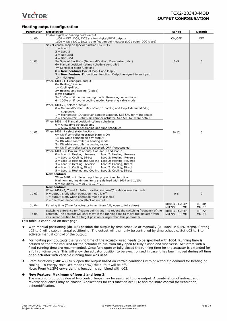
TCX2-23343-MOD
OUTPUT CONFIGURATION
Doc: 70-00-0623, V1.3R0, 20170131 © Vector Controls GmbH, Switzerland Page 34
Subject to alteration www.vectorcontrols.com
Floating output configuration
Parameter Description Range Default
1d 00
Enable digital or floating point output
1d00 = OFF: DO1, DO2 are two digital/PWM outputs
1d00 = ON : DO1, DO2 is one floating point output (DO1 open, DO2 close)
ON/OFF OFF
1d 01
Select control loop or special function (0= OFF)
1 = Loop 1
2 = Loop 2
3 = Not used 4 = Not used
5= Special functions (Dehumidification, Economizer, etc.)
6= Manual positioning/time schedule controlled
7= Controller state functions
8 = New Feature: Max of loop 1 and loop 2
9 = New Feature: Proportional function: Output assigned to an input
10 = Not used
0–9 0
1d 02
When 1d01=1-4 configure output:
0= Heating/reverse
1= Cooling/direct 2= Heating and cooling (2 pipe) New Feature:
3= 100% on if loop in heating mode: Reversing valve mode
4= 100% on if loop in cooling mode: Reversing valve mode
0–12 0
When 1d01=5, select function:
0 = Dehumidification: Max of loop 1 cooling and loop 2 dehumidifying
sequence.
1 = Economizer: Outdoor air damper actuator. See 5FU for more details.
2 = Economizer: Return air damper actuator. See 5FU for more details.
When 1d01 = 6 Manual positioning/time schedules
0 = Allow time schedule only
1 = Allow manual positioning and time schedules
When 1d01=7 select state functions:
0= ON if controller operation state is ON
1= ON while demand on any output 2= ON while controller in heating mode
3= ON while controller in cooling mode
4= ON if controller state is occupied, OFF if unoccupied
When 1d01 = 8 Maximum of output of loop 1 and loop 2
0 = Loop 1: Heating, Reverse Loop 2: Heating, Reverse
1 = Loop 1: Cooling, Direct Loop 2: Heating, Reverse
2 = Loop 1: Heating and Cooling Loop 2: Heating, Reverse
3 = Loop 1: Heating, Reverse Loop 2: Cooling, Direct
4 = Loop 1: Cooling, Direct Loop 2: Cooling, Direct
5 = Loop 1: Heating and Cooling Loop 2: Cooling, Direct
New Feature:
When 1d01 = 9: Select input for proportional function.
Minimum and maximum limits are defined with 1d14 and 1d15: 0 = not active, 1 = UI 1 to 12 = VI4
1d 03
New Feature:
When 1d01=6, 7 and 9: Select reaction on on/off/disable operation mode
0 = output is off, when operation mode is off
1 = output is off, when operation mode is disabled
2 = operation mode has no effect on output
0-6 0
1d 04 Running time (Time for actuator to run from fully open to fully close) 00:00s...15:10h MM:SS...HH:MM
00:00s MM:SS
1d 05
Switching difference for floating point signal: to reduce the switching frequency of the
actuator. The actuator will only move if the running time to move the actuator from
its current position to the target position is larger than this parameter.
00:00s...15:10h
MM:SS...HH:MM
00:05s
MM:SS
This table is continued on next page.
With manual positioning (d01=6) position the output by time schedule or manually (0…100% in 0.5% steps). Setting d02 to 0 will disable manual positioning. The output will then only be controlled by time schedule. Set d02 to 1 to activate manual control of the output.
For floating point outputs the running time of the actuator used needs to be specified with 1d04. Running time is defined as the time required for the actuator to run from fully open to fully closed and vice versa. Actuators with a fixed running time are recommended. Once fully open or fully closed the running time for the actuator is extended for a full run-time cycle. This will allow the actuator position to be synchronized in case it has been moved during off time or an actuator with variable running time was used.
State functions (1d01=7) fully open the output based on certain conditions with or without a demand for heating or cooling. In Energy Hold OFF mode (EHO) the output will be off. Note: From V1.2R6 onwards, this function is combined with d03.
New Feature: Maximum of loop 1 and loop 2: The maximum output value of two control loops may be assigned to one output. A combination of indirect and reverse sequences may be chosen. Applications for this function are CO2 and moisture control for ventilation, dehumidification.
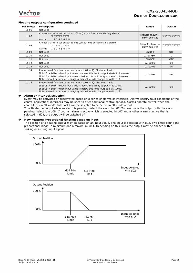
TCX2-23343-MOD
OUTPUT CONFIGURATION
Doc: 70-00-0623, V1.3R0, 20170131 © Vector Controls GmbH, Switzerland Page 35
Subject to alteration www.vectorcontrols.com
Floating outputs configuration continued
Parameter Description Range Default
1d 06 Not used
1d 07
Choose alarm to set output to 100% (output 0% on conflicting alarms)
Alarm: 1 2 3 4 5 6 7 8
Triangle shown =
alarm selected
1d 08
Choose alarm to set output to 0% (output 0% on conflicting alarms)
Alarm: 1 2 3 4 5 6 7 8
Triangle shown =
alarm selected
1d 09 Not used ON/OFF OFF
1d 10 Not used 0...10750h 0
1d 11 Not used ON/OFF OFF
1d 12 Not used 0...100% 0%
1d 13 Not used 0...100% 0%
1d 14 Proportional function based on input (1d01 = 9): Minimum limit :
If 1d15 > 1d14: when input value is above this limit, output starts to increase.
If 1d15 < 1d14: when input value is below this limit, output starts to increase. Note: shared parameter: changing this value, will change as well 1d12
0...100% 0%
1d 15 Proportional function based on input (1d01 = 9): Maximum limit :
If 1d15 > 1d14: when input value is above this limit, output is at 100%.
If 1d15 < 1d14: when input value is below this limit, output is at 100%. Note: shared parameter: changing this value, will change as well 1d13
0...100% 0%
Alarm or interlock selection: Every may be activated or deactivated based on a series of alarms or interlocks. Alarms specify fault conditions of the control application; interlocks may be used to offer additional control options. Alarms operate as well when the controller is in off mode. Interlocks can be selected to be active in off mode or not. To activate the output while an alarm is pending, select the alarm in d07. To deactivate the output with the alarm pending, select it in d08. If both an alarm is active which is selected in d07 and another alarm is active that is selected in d08, the output will be switched off.
New Feature: Proportional function based on input: The position of a floating output may be based on an input value. The input is selected with d02. Two limits define the proportional range: A minimum and a maximum limit. Depending on this limits the output may be opened with a sinking or a rising input signal.
100%
0%
d14 Min Limit
d15 Max Limit
Output Position
Input selected with d02
100%
0%
d15 Max Limit
d14 Min Limit
Output Position
Input selected with d02
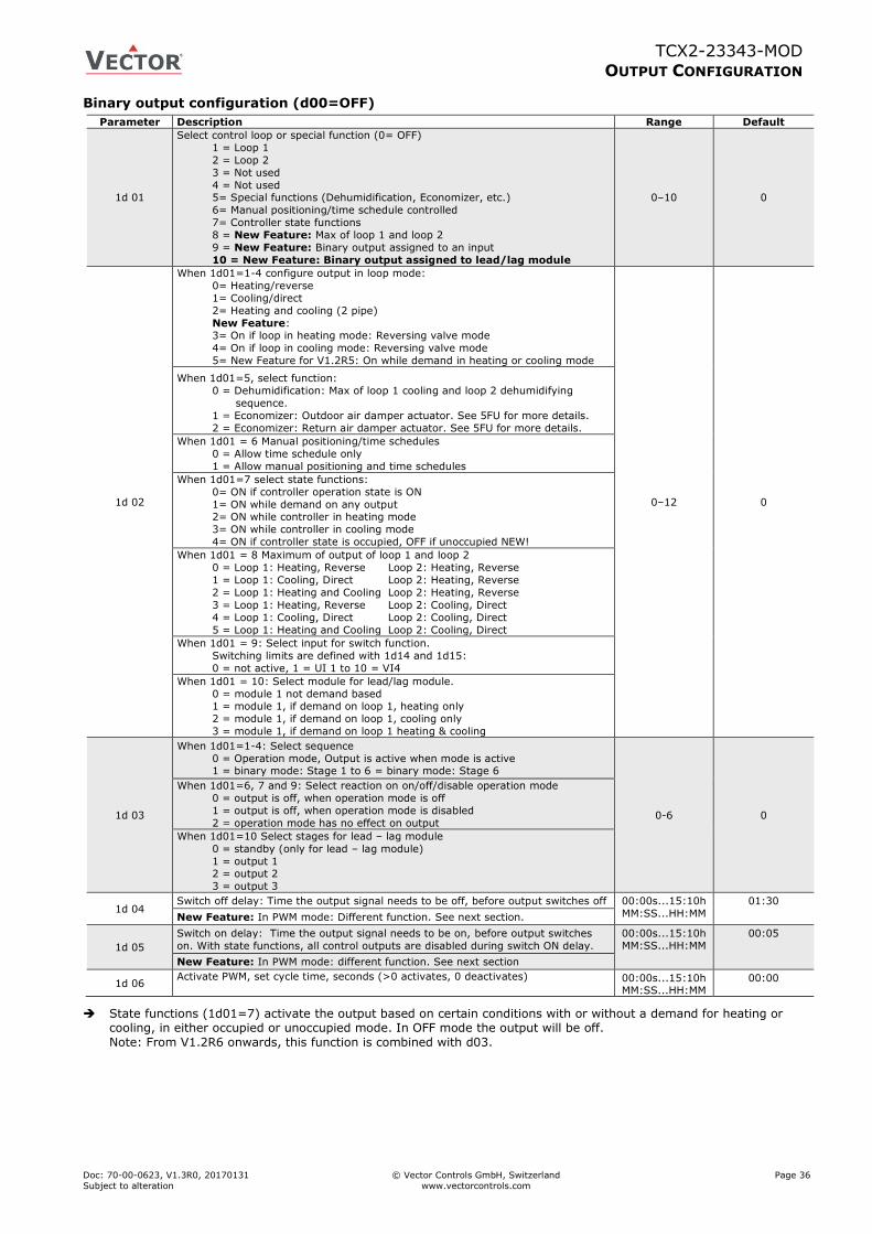
TCX2-23343-MOD
OUTPUT CONFIGURATION
Doc: 70-00-0623, V1.3R0, 20170131 © Vector Controls GmbH, Switzerland Page 36
Subject to alteration www.vectorcontrols.com
Binary output configuration (d00=OFF)
Parameter Description Range Default
1d 01
Select control loop or special function (0= OFF)
1 = Loop 1
2 = Loop 2
3 = Not used
4 = Not used 5= Special functions (Dehumidification, Economizer, etc.)
6= Manual positioning/time schedule controlled
7= Controller state functions
8 = New Feature: Max of loop 1 and loop 2
9 = New Feature: Binary output assigned to an input
10 = New Feature: Binary output assigned to lead/lag module
0–10 0
1d 02
When 1d01=1-4 configure output in loop mode:
0= Heating/reverse
1= Cooling/direct 2= Heating and cooling (2 pipe)
New Feature: 3= On if loop in heating mode: Reversing valve mode
4= On if loop in cooling mode: Reversing valve mode
5= New Feature for V1.2R5: On while demand in heating or cooling mode
0–12 0
When 1d01=5, select function:
0 = Dehumidification: Max of loop 1 cooling and loop 2 dehumidifying
sequence.
1 = Economizer: Outdoor air damper actuator. See 5FU for more details.
2 = Economizer: Return air damper actuator. See 5FU for more details.
When 1d01 = 6 Manual positioning/time schedules
0 = Allow time schedule only
1 = Allow manual positioning and time schedules
When 1d01=7 select state functions:
0= ON if controller operation state is ON
1= ON while demand on any output 2= ON while controller in heating mode
3= ON while controller in cooling mode
4= ON if controller state is occupied, OFF if unoccupied NEW!
When 1d01 = 8 Maximum of output of loop 1 and loop 2
0 = Loop 1: Heating, Reverse Loop 2: Heating, Reverse
1 = Loop 1: Cooling, Direct Loop 2: Heating, Reverse
2 = Loop 1: Heating and Cooling Loop 2: Heating, Reverse
3 = Loop 1: Heating, Reverse Loop 2: Cooling, Direct
4 = Loop 1: Cooling, Direct Loop 2: Cooling, Direct
5 = Loop 1: Heating and Cooling Loop 2: Cooling, Direct
When 1d01 = 9: Select input for switch function.
Switching limits are defined with 1d14 and 1d15:
0 = not active, 1 = UI 1 to 10 = VI4
When 1d01 = 10: Select module for lead/lag module.
0 = module 1 not demand based 1 = module 1, if demand on loop 1, heating only
2 = module 1, if demand on loop 1, cooling only
3 = module 1, if demand on loop 1 heating & cooling
1d 03
When 1d01=1-4: Select sequence
0 = Operation mode, Output is active when mode is active 1 = binary mode: Stage 1 to 6 = binary mode: Stage 6
0-6 0
When 1d01=6, 7 and 9: Select reaction on on/off/disable operation mode
0 = output is off, when operation mode is off
1 = output is off, when operation mode is disabled
2 = operation mode has no effect on output
When 1d01=10 Select stages for lead – lag module
0 = standby (only for lead – lag module)
1 = output 1 2 = output 2
3 = output 3
1d 04 Switch off delay: Time the output signal needs to be off, before output switches off 00:00s...15:10h
MM:SS...HH:MM
01:30
New Feature: In PWM mode: Different function. See next section.
1d 05
Switch on delay: Time the output signal needs to be on, before output switches
on. With state functions, all control outputs are disabled during switch ON delay.
00:00s...15:10h MM:SS...HH:MM
00:05
New Feature: In PWM mode: different function. See next section
1d 06 Activate PWM, set cycle time, seconds (>0 activates, 0 deactivates) 00:00s...15:10h
MM:SS...HH:MM 00:00
State functions (1d01=7) activate the output based on certain conditions with or without a demand for heating or cooling, in either occupied or unoccupied mode. In OFF mode the output will be off.
Note: From V1.2R6 onwards, this function is combined with d03.
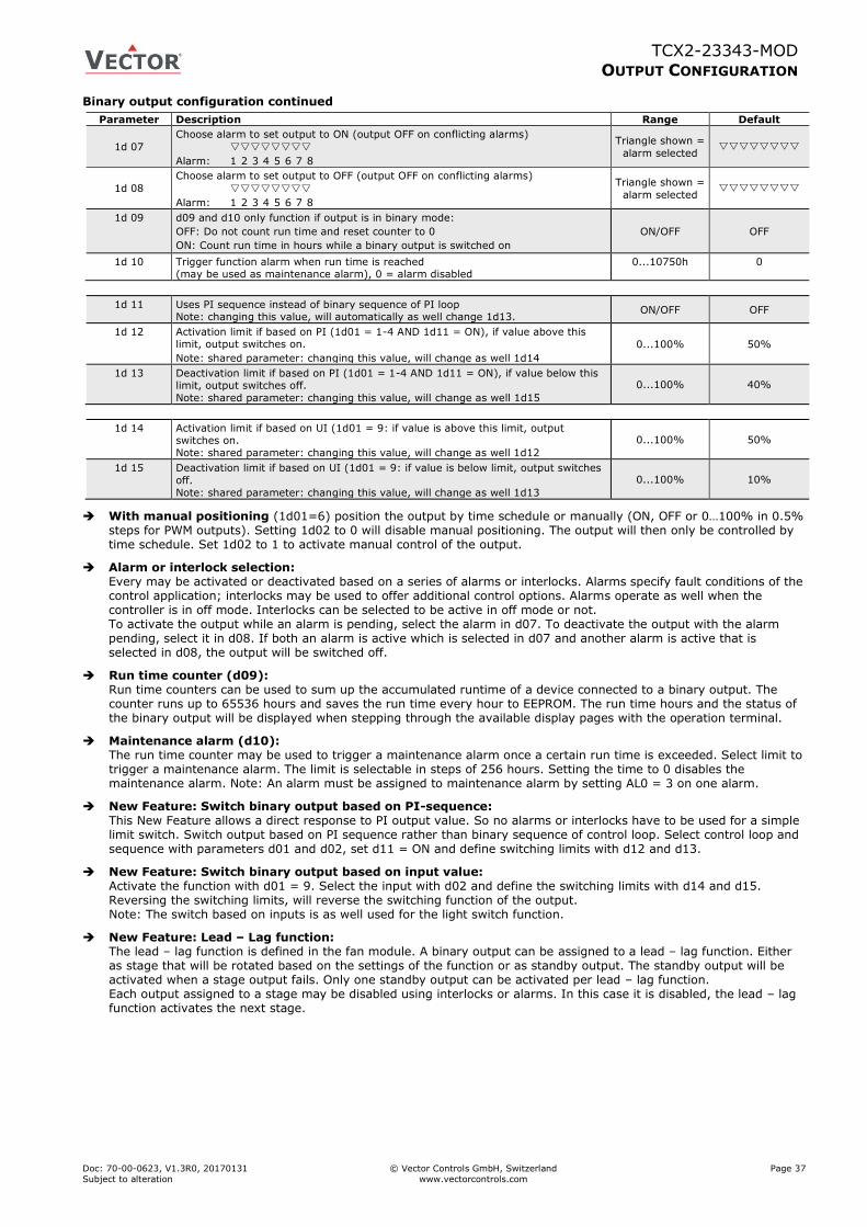
TCX2-23343-MOD
OUTPUT CONFIGURATION
Doc: 70-00-0623, V1.3R0, 20170131 © Vector Controls GmbH, Switzerland Page 37
Subject to alteration www.vectorcontrols.com
Binary output configuration continued
Parameter Description Range Default
1d 07
Choose alarm to set output to ON (output OFF on conflicting alarms)
Alarm: 1 2 3 4 5 6 7 8
Triangle shown =
alarm selected
1d 08
Choose alarm to set output to OFF (output OFF on conflicting alarms)
Alarm: 1 2 3 4 5 6 7 8
Triangle shown =
alarm selected
1d 09 d09 and d10 only function if output is in binary mode:
OFF: Do not count run time and reset counter to 0
ON: Count run time in hours while a binary output is switched on
ON/OFF OFF
1d 10 Trigger function alarm when run time is reached (may be used as maintenance alarm), 0 = alarm disabled
0...10750h 0
1d 11 Uses PI sequence instead of binary sequence of PI loop Note: changing this value, will automatically as well change 1d13.
ON/OFF OFF
1d 12 Activation limit if based on PI (1d01 = 1-4 AND 1d11 = ON), if value above this limit, output switches on.
Note: shared parameter: changing this value, will change as well 1d14
0...100% 50%
1d 13 Deactivation limit if based on PI (1d01 = 1-4 AND 1d11 = ON), if value below this limit, output switches off.
Note: shared parameter: changing this value, will change as well 1d15
0...100% 40%
1d 14 Activation limit if based on UI (1d01 = 9: if value is above this limit, output switches on.
Note: shared parameter: changing this value, will change as well 1d12
0...100% 50%
1d 15 Deactivation limit if based on UI (1d01 = 9: if value is below limit, output switches
off.
Note: shared parameter: changing this value, will change as well 1d13
0...100% 10%
With manual positioning (1d01=6) position the output by time schedule or manually (ON, OFF or 0…100% in 0.5% steps for PWM outputs). Setting 1d02 to 0 will disable manual positioning. The output will then only be controlled by time schedule. Set 1d02 to 1 to activate manual control of the output.
Alarm or interlock selection: Every may be activated or deactivated based on a series of alarms or interlocks. Alarms specify fault conditions of the control application; interlocks may be used to offer additional control options. Alarms operate as well when the controller is in off mode. Interlocks can be selected to be active in off mode or not. To activate the output while an alarm is pending, select the alarm in d07. To deactivate the output with the alarm pending, select it in d08. If both an alarm is active which is selected in d07 and another alarm is active that is selected in d08, the output will be switched off.
Run time counter (d09): Run time counters can be used to sum up the accumulated runtime of a device connected to a binary output. The counter runs up to 65536 hours and saves the run time every hour to EEPROM. The run time hours and the status of the binary output will be displayed when stepping through the available display pages with the operation terminal.
Maintenance alarm (d10): The run time counter may be used to trigger a maintenance alarm once a certain run time is exceeded. Select limit to trigger a maintenance alarm. The limit is selectable in steps of 256 hours. Setting the time to 0 disables the maintenance alarm. Note: An alarm must be assigned to maintenance alarm by setting AL0 = 3 on one alarm.
New Feature: Switch binary output based on PI-sequence: This New Feature allows a direct response to PI output value. So no alarms or interlocks have to be used for a simple limit switch. Switch output based on PI sequence rather than binary sequence of control loop. Select control loop and sequence with parameters d01 and d02, set d11 = ON and define switching limits with d12 and d13.
New Feature: Switch binary output based on input value: Activate the function with d01 = 9. Select the input with d02 and define the switching limits with d14 and d15. Reversing the switching limits, will reverse the switching function of the output. Note: The switch based on inputs is as well used for the light switch function.
New Feature: Lead – Lag function: The lead – lag function is defined in the fan module. A binary output can be assigned to a lead – lag function. Either as stage that will be rotated based on the settings of the function or as standby output. The standby output will be activated when a stage output fails. Only one standby output can be activated per lead – lag function. Each output assigned to a stage may be disabled using interlocks or alarms. In this case it is disabled, the lead – lag function activates the next stage.
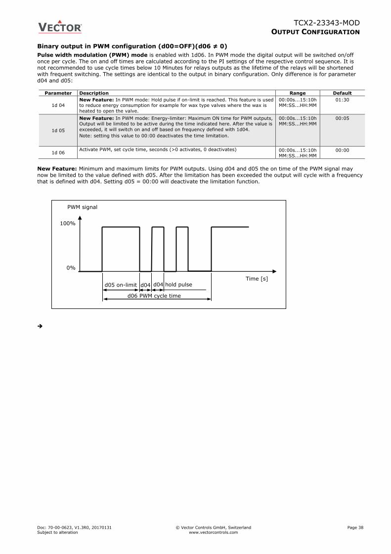
TCX2-23343-MOD
OUTPUT CONFIGURATION
Doc: 70-00-0623, V1.3R0, 20170131 © Vector Controls GmbH, Switzerland Page 38
Subject to alteration www.vectorcontrols.com
Binary output in PWM configuration (d00=OFF)(d06 ≠ 0)
Pulse width modulation (PWM) mode is enabled with 1d06. In PWM mode the digital output will be switched on/off once per cycle. The on and off times are calculated according to the PI settings of the respective control sequence. It is not recommended to use cycle times below 10 Minutes for relays outputs as the lifetime of the relays will be shortened with frequent switching. The settings are identical to the output in binary configuration. Only difference is for parameter d04 and d05:
Parameter Description Range Default
1d 04 New Feature: In PWM mode: Hold pulse if on-limit is reached. This feature is used to reduce energy consumption for example for wax type valves where the wax is
heated to open the valve.
00:00s...15:10h MM:SS...HH:MM
01:30
1d 05
New Feature: In PWM mode: Energy-limiter: Maximum ON time for PWM outputs, Output will be limited to be active during the time indicated here. After the value is
exceeded, it will switch on and off based on frequency defined with 1d04.
Note: setting this value to 00:00 deactivates the time limitation.
00:00s...15:10h MM:SS...HH:MM
00:05
1d 06 Activate PWM, set cycle time, seconds (>0 activates, 0 deactivates) 00:00s...15:10h
MM:SS...HH:MM 00:00
New Feature: Minimum and maximum limits for PWM outputs. Using d04 and d05 the on time of the PWM signal may now be limited to the value defined with d05. After the limitation has been exceeded the output will cycle with a frequency that is defined with d04. Setting d05 = 00:00 will deactivate the limitation function.
100%
0%
d06 PWM cycle time
PWM signal
Time [s] d05 on-limit d04 hold pulse d04
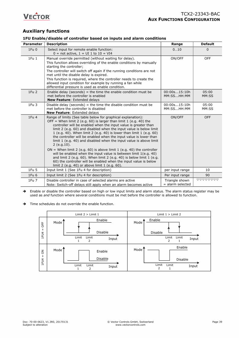
TCX2-23343-BAC
AUX FUNCTIONS CONFIGURATION
Doc: 70-00-0623, V1.3R0, 20170131 © Vector Controls GmbH, Switzerland Page 39
Subject to alteration www.vectorcontrols.com
Auxiliary functions
1FU Enable/disable of controller based on inputs and alarm conditions
Parameter Description Range Default
1Fu 0 Select input for remote enable function: 0 = not active, 1 = UI 1 to 10 = VI4
0…10 0
1Fu 1 Manual override permitted (without waiting for delay).
This function allows overriding of the enable conditions by manually starting the controller;
The controller will switch off again if the running conditions are not met until the disable delay is expired.
This function is required, where the controller needs to create the allowed input condition for example by running a fan while differential pressure is used as enable condition.
ON/OFF OFF
1Fu 2 Enable delay (seconds) = the time the enable condition must be met before the controller is enabled New Feature: Extended delays
00:00s...15:10h MM:SS...HH:MM
05:00 MM:SS
1Fu 3 Disable delay (seconds) = the time the disable condition must be met before the controller is disabled New Feature: Extended delays
00:00s...15:10h MM:SS...HH:MM
05:00 MM:SS
1Fu 4 Range of limits (See table below for graphical explanation): OFF = When limit 2 (e.g. 60) is larger than limit 1 (e.g. 40) the
controller will be enabled when the input value is greater than limit 2 (e.g. 60) and disabled when the input value is below limit 1 (e.g. 40). When limit 2 (e.g. 40) is lower than limit 1 (e.g. 60) the controller will be enabled when the input value is lower than limit 1 (e.g. 40) and disabled when the input value is above limit 2 (e.g.10).
ON = When limit 2 (e.g. 60) is above limit 1 (e.g. 40) the controller will be enabled when the input value is between limit 1(e.g. 40) and limit 2 (e.g. 60). When limit 2 (e.g. 40) is below limit 1 (e.g. 60) the controller will be enabled when the input value is below limit 2 (e.g. 40) or above limit 1 (e.g. 60).
ON/OFF OFF
1Fu 5 Input limit 1 (See 1Fu 4 for description) per input range 10
1Fu 6 Input limit 2 (See 1Fu 4 for description) Per input range 90
1Fu 7 Disable controller in case of selected alarms are active
Note: Switch-off delays still apply when an alarm becomes active
Triangle shown = alarm selected
Enable or disable the controller based on high or low input limits and alarm status. The alarm status register may be used as and function where several conditions must be met before the controller is allowed to function.
Time schedules do not override the enable function.
Limit 2 > Limit 1
Limit 1 > Limit 2
Enable
Disable
Input
Mode Enable
Disable
Input
Mode
1FU
4 =
OFF
1FU
4 =
ON
Enable
Disable
Input
Mode Enable
Disable
Input
Mode
Limit
1
Limit
2
Limit
2
Limit
1
Limit
1
Limit
2
Limit
2 Limit
1
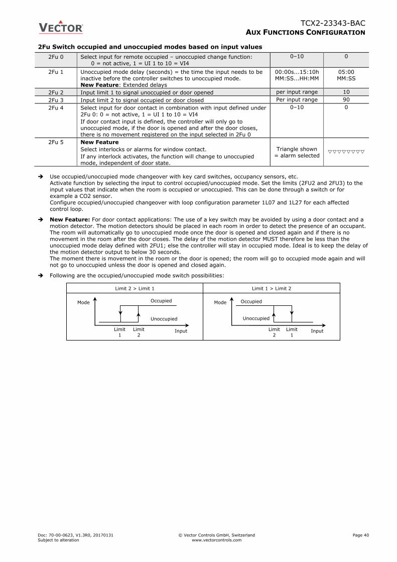
TCX2-23343-BAC
AUX FUNCTIONS CONFIGURATION
Doc: 70-00-0623, V1.3R0, 20170131 © Vector Controls GmbH, Switzerland Page 40
Subject to alteration www.vectorcontrols.com
2Fu Switch occupied and unoccupied modes based on input values
2Fu 0 Select input for remote occupied – unoccupied change function: 0 = not active, 1 = UI 1 to 10 = VI4
0–10 0
2Fu 1 Unoccupied mode delay (seconds) = the time the input needs to be inactive before the controller switches to unoccupied mode. New Feature: Extended delays
00:00s...15:10h MM:SS...HH:MM
05:00 MM:SS
2Fu 2 Input limit 1 to signal unoccupied or door opened per input range 10
2Fu 3 Input limit 2 to signal occupied or door closed Per input range 90
2Fu 4 Select input for door contact in combination with input defined under
2Fu 0: 0 = not active, 1 = UI 1 to 10 = VI4
If door contact input is defined, the controller will only go to unoccupied mode, if the door is opened and after the door closes, there is no movement registered on the input selected in 2Fu 0
0–10 0
2Fu 5 New Feature
Select interlocks or alarms for window contact.
If any interlock activates, the function will change to unoccupied mode, independent of door state.
Triangle shown = alarm selected
Use occupied/unoccupied mode changeover with key card switches, occupancy sensors, etc.
Activate function by selecting the input to control occupied/unoccupied mode. Set the limits (2FU2 and 2FU3) to the input values that indicate when the room is occupied or unoccupied. This can be done through a switch or for example a CO2 sensor. Configure occupied/unoccupied changeover with loop configuration parameter 1L07 and 1L27 for each affected control loop.
New Feature: For door contact applications: The use of a key switch may be avoided by using a door contact and a motion detector. The motion detectors should be placed in each room in order to detect the presence of an occupant. The room will automatically go to unoccupied mode once the door is opened and closed again and if there is no movement in the room after the door closes. The delay of the motion detector MUST therefore be less than the unoccupied mode delay defined with 2FU1; else the controller will stay in occupied mode. Ideal is to keep the delay of the motion detector output to below 30 seconds. The moment there is movement in the room or the door is opened; the room will go to occupied mode again and will not go to unoccupied unless the door is opened and closed again.
Following are the occupied/unoccupied mode switch possibilities:
Unoccupied
Mode Mode Occupied
Input
Limit 2 > Limit 1
Occupied
Unoccupied
Input
Limit 1 > Limit 2
Limit
1
Limit
2
Limit
2
Limit
1
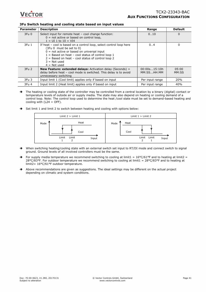
TCX2-23343-BAC
AUX FUNCTIONS CONFIGURATION
Doc: 70-00-0623, V1.3R0, 20170131 © Vector Controls GmbH, Switzerland Page 41
Subject to alteration www.vectorcontrols.com
3Fu Switch heating and cooling state based on input values
Parameter Description Range Default
3Fu 0 Select input for remote heat – cool change function:
0 = not active or based on control loop, 1 = UI 1 to 10 = VI4
0…10 0
3Fu 1 If heat – cool is based on a control loop, select control loop here (3Fu 0 must be set to 0) 0 = not active or based on universal input 1 = Based on heat – cool status of control loop 1 2 = Based on heat – cool status of control loop 2 3 = Not used 4 = Not used
0…4 0
3Fu 2 New Feature: extended delays: Activation delay (Seconds) = delay before heat – cool mode is switched. This delay is to avoid unnecessary switching
00:00s...15:10h MM:SS...HH:MM
05:00 MM:SS
3Fu 3 Input limit 1 (Cool limit) applies only if based on input Per input range 20%
3Fu 4 Input limit 2 (Heat limit) applies only if based on input Per input range 40%
The heating or cooling state of the controller may be controlled from a central location by a binary (digital) contact or
temperature levels of outside air or supply media. The state may also depend on heating or cooling demand of a control loop. Note: The control loop used to determine the heat /cool state must be set to demand-based heating and cooling with (L24 = OFF).
Set limit 1 and limit 2 to switch between heating and cooling with options below:
When switching heating/cooling state with an external switch set input to RT/DI mode and connect switch to signal ground. Ground levels of all involved controllers must be the same.
For supply media temperature we recommend switching to cooling at limit1 = 16°C/61°F and to heating at limit2 = 28°C/83°F. For outdoor temperature we recommend switching to cooling at limit1 = 28°C/83°F and to heating at limit2= 16°C/61°F outdoor temperature.
Above recommendations are given as suggestions. The ideal settings may be different on the actual project depending on climatic and system conditions.
Cool
Mode Mode Heat
Input
Limit 2 > Limit 1
Heat
Cool
Input
Limit 1 > Limit 2
Limit
1
Limit
2
Limit
2
Limit
1
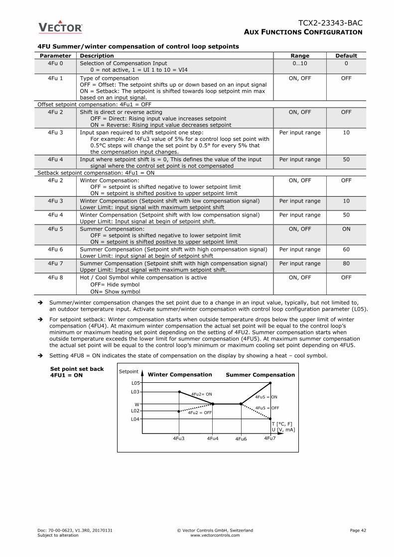
TCX2-23343-BAC
AUX FUNCTIONS CONFIGURATION
Doc: 70-00-0623, V1.3R0, 20170131 © Vector Controls GmbH, Switzerland Page 42
Subject to alteration www.vectorcontrols.com
4FU Summer/winter compensation of control loop setpoints
Parameter Description Range Default
4Fu 0 Selection of Compensation Input
0 = not active, 1 = UI 1 to 10 = VI4
0…10 0
4Fu 1 Type of compensation OFF = Offset: The setpoint shifts up or down based on an input signal ON = Setback: The setpoint is shifted towards loop setpoint min max based on an input signal.
ON, OFF OFF
Offset setpoint compensation: 4Fu1 = OFF
4Fu 2 Shift is direct or reverse acting OFF = Direct: Rising input value increases setpoint ON = Reverse: Rising input value decreases setpoint
ON, OFF OFF
4Fu 3 Input span required to shift setpoint one step:
For example: An 4Fu3 value of 5% for a control loop set point with 0.5°C steps will change the set point by 0.5° for every 5% that the compensation input changes.
Per input range 10
4Fu 4 Input where setpoint shift is = 0, This defines the value of the input signal where the control set point is not compensated
Per input range 50
Setback setpoint compensation: 4Fu1 = ON
4Fu 2 Winter Compensation: OFF = setpoint is shifted negative to lower setpoint limit ON = setpoint is shifted positive to upper setpoint limit
ON, OFF OFF
4Fu 3 Winter Compensation (Setpoint shift with low compensation signal) Lower Limit: input signal with maximum setpoint shift
Per input range 10
4Fu 4 Winter Compensation (Setpoint shift with low compensation signal)
Upper Limit: Input signal at begin of setpoint shift.
Per input range 50
4Fu 5 Summer Compensation: OFF = setpoint is shifted negative to lower setpoint limit ON = setpoint is shifted positive to upper setpoint limit
ON, OFF ON
4Fu 6 Summer Compensation (Setpoint shift with high compensation signal)
Lower Limit: input signal at begin of setpoint shift
Per input range 60
4Fu 7 Summer Compensation (Setpoint shift with high compensation signal) Upper Limit: Input signal with maximum setpoint shift.
Per input range 80
4Fu 8 Hot / Cool Symbol while compensation is active
OFF= Hide symbol
ON= Show symbol
ON, OFF OFF
Summer/winter compensation changes the set point due to a change in an input value, typically, but not limited to, an outdoor temperature input. Activate summer/winter compensation with control loop configuration parameter (L05).
For setpoint setback: Winter compensation starts when outside temperature drops below the upper limit of winter compensation (4FU4). At maximum winter compensation the actual set point will be equal to the control loop’s minimum or maximum heating set point depending on the setting of 4FU2. Summer compensation starts when outside temperature exceeds the lower limit for summer compensation (4FU5). At maximum summer compensation the actual set point will be equal to the control loop’s minimum or maximum cooling set point depending on 4FU5.
Setting 4FU8 = ON indicates the state of compensation on the display by showing a heat – cool symbol.
Winter Compensation Summer Compensation
L03
T [°C, F]
U [V, mA]
4Fu3
4Fu2= ON
4Fu4
L02 4Fu2 = OFF
Setpoint
4Fu5 = ON
L05
4Fu6 4Fu7
W
L04
4Fu5 = OFF
Set point set back 4FU1 = ON
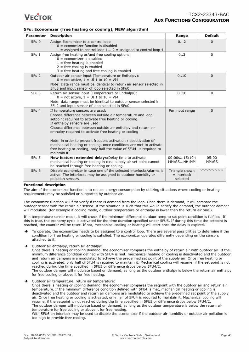
TCX2-23343-BAC
AUX FUNCTIONS CONFIGURATION
Doc: 70-00-0623, V1.3R0, 20170131 © Vector Controls GmbH, Switzerland Page 43
Subject to alteration www.vectorcontrols.com
5Fu: Economizer (free heating or cooling), NEW algorithm!
Parameter Description Range Default
5Fu 0 Assign Economizer to a control loop 0 = economizer function is disabled 1 = assigned to control loop 1... 2 = assigned to control loop 4
0...2 0
5Fu 1 Assign free heating or/and free cooling options
0 = economizer is disabled 1 = free heating is enabled 2 = free cooling is enabled 3 = free heating and free cooling is enabled
0..3 0
5Fu 2 Outdoor air sensor input (Temperature or Enthalpy): 0 = not active, 1 = UI 1 to 10 = VI4
Note: Data range must be identical to return air sensor selected in
5Fu3 and input sensor of loop selected in 5Fu0.
0..10 0
5Fu 3 Return air sensor input (Temperature or Enthalpy): 0 = not active, 1 = UI 1 to 10 = VI4
Note: data range must be identical to outdoor sensor selected in
5Fu2 and input sensor of loop selected in 5Fu0.
0..10 0
5Fu 4 If temperature sensors are used:
Choose difference between outside air temperature and loop
setpoint required to activate free heating or cooling. If enthalpy sensors are used:
Choose difference between outside air enthalpy and return air enthalpy required to activate free heating or cooling
Note: in order to prevent frequent activation / deactivation of
mechanical heating or cooling, once conditions are met to activate free heating or cooling, only half the value of 5FU4 is required to maintain it.
Per input range 0
5Fu 5 New feature: extended delays:Delay time to activate mechanical heating or cooling in case supply air set point cannot
be reached through free heating or cooling.
00:00s...15:10h MM:SS...HH:MM
05:00 MM:SS
5Fu 6 Disable economizer in case one of the selected interlocks/alarms is active. The interlocks may be assigned to outdoor humidity or pollution sensors
Triangle shown = interlock selected
Functional description
The aim of the economizer function is to reduce energy consumption by utilizing situations where cooling or heating requirements may be satisfied or supported by outdoor air.
The economize function will first verify if there is demand from the loop. Once there is demand, it will compare the outdoor sensor with the return air sensor. If the situation is such that this would satisfy the demand, the outdoor damper will modulate. (for example if cooling mode, outdoor temperature or enthalpy is lower than the return air one.).
If in temperature sensor mode, it will check if the minimum difference outdoor temp to set point condition is fulfilled. If this is true, the economy cycle is activated for the time duration specified under 5FU5. If during this time the setpoint is reached, the counter will be reset. If not, mechanical cooling or heating will start once the delay is expired.
To operate, the economizer needs to be assigned to a control loop. There are several possibilities to determine if the condition for free heating or cooling is satisfied. The economizer operates differently depending on the sensors attached to it.
Outdoor air enthalpy, return air enthalpy: Once there is heating or cooling demand, the economizer compares the enthalpy of return air with outdoor air. If the minimum difference condition defined with 5FU4 is met, mechanical heating or cooling is deactivated and the outdoor and return air dampers are modulated to achieve the predefined set point of the supply air. Once free heating or cooling is activated, only half of 5FU4 is required to maintain it. Mechanical cooling will resume, if the set point is not reached during the time specified in 5FU5 or difference drops below 5FU4/2. The outdoor damper will modulate based on demand, as long as the outdoor enthalpy is below the return air enthalpy for free cooling or above it for free heating.
Outdoor air temperature, return air temperature: Once there is heating or cooling demand, the economizer compares the setpoint with the outdoor air and return air temperature. If the minimum difference condition defined with 5FU4 is met, mechanical heating or cooling is deactivated and the outdoor and return air dampers are modulated to achieve the predefined set point of the supply air. Once free heating or cooling is activated, only half of 5FU4 is required to maintain it. Mechanical cooling will resume, if the setpoint is not reached during the time specified in 5FU5 or difference drops below 5FU4/2. The outdoor damper will modulate based on demand, as long as the outdoor temperature is below the return air temperature for free cooling or above it for free heating. With 5FU6 an interlock may be used to disable the economizer if the outdoor air humidity or outdoor air pollution is too high to provide free cooling.

TCX2-23343-BAC
AUX FUNCTIONS CONFIGURATION
Doc: 70-00-0623, V1.3R0, 20170131 © Vector Controls GmbH, Switzerland Page 44
Subject to alteration www.vectorcontrols.com
Outdoor air temperature only: Once there is heating or cooling demand, the economizer compares the setpoint with the outdoor air temperature. If the minimum difference condition defined with 5FU4 is met, mechanical heating or cooling is deactivated and the outdoor and return air dampers are modulated to achieve the predefined set point of the supply air. Mechanical cooling will resume if the setpoint is not reached during the time specified in 5FU5. With 5FU6 an interlock may be used to disable the economizer if the outdoor air humidity or outdoor air pollution is for too high to provide free cooling.
Important note: All involved sensors must have the identical range settings (xu1 and xu2). This includes the sensor used for the control loop!
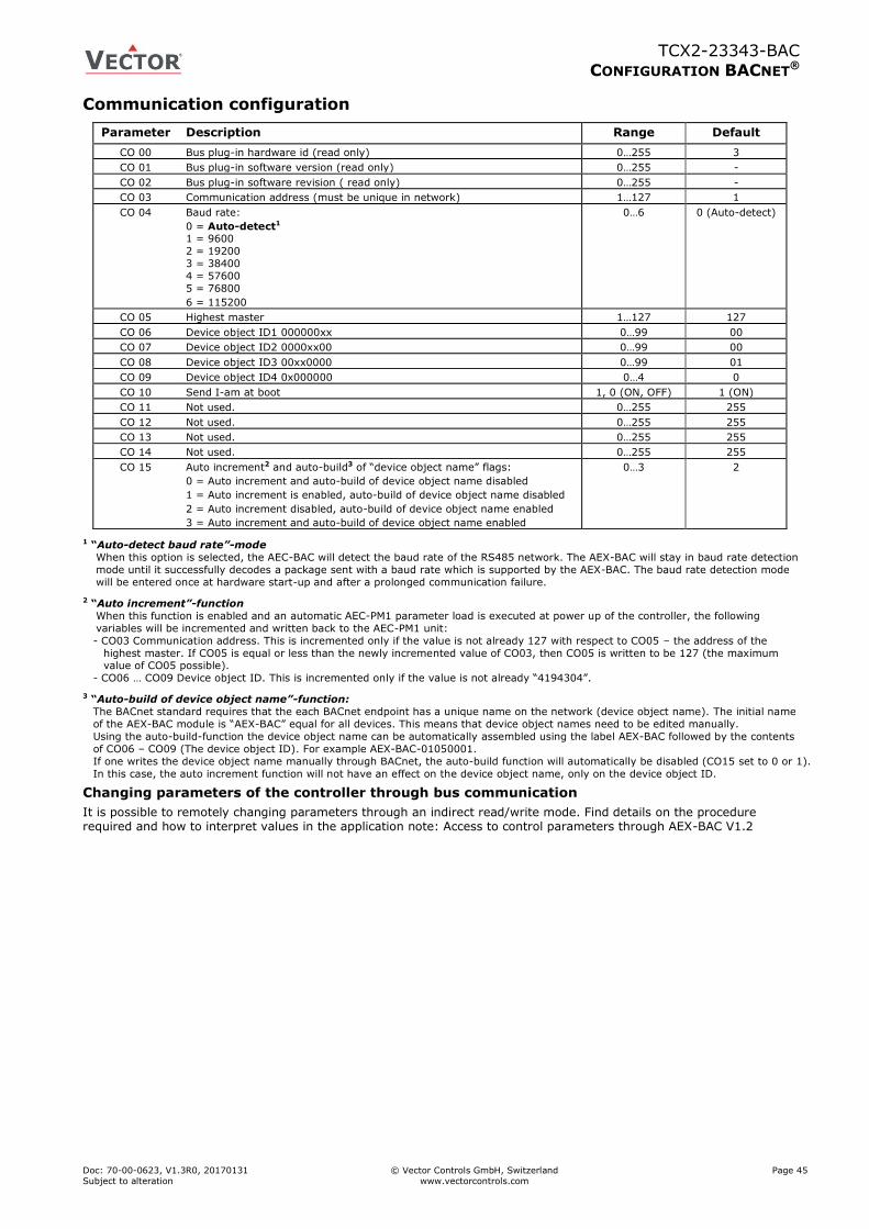
TCX2-23343-BAC
CONFIGURATION BACNET®
Doc: 70-00-0623, V1.3R0, 20170131 © Vector Controls GmbH, Switzerland Page 45
Subject to alteration www.vectorcontrols.com
Communication configuration
Parameter Description Range Default
CO 00 Bus plug-in hardware id (read only) 0…255 3
CO 01 Bus plug-in software version (read only) 0…255 -
CO 02 Bus plug-in software revision ( read only) 0…255 -
CO 03 Communication address (must be unique in network) 1…127 1
CO 04 Baud rate:
0 = Auto-detect1 1 = 9600
2 = 19200
3 = 38400
4 = 57600
5 = 76800
6 = 115200
0…6 0 (Auto-detect)
CO 05 Highest master 1…127 127
CO 06 Device object ID1 000000xx 0…99 00
CO 07 Device object ID2 0000xx00 0…99 00
CO 08 Device object ID3 00xx0000 0…99 01
CO 09 Device object ID4 0x000000 0…4 0
CO 10 Send I-am at boot 1, 0 (ON, OFF) 1 (ON)
CO 11 Not used. 0…255 255
CO 12 Not used. 0…255 255
CO 13 Not used. 0…255 255
CO 14 Not used. 0…255 255
CO 15 Auto increment2 and auto-build3 of “device object name” flags:
0 = Auto increment and auto-build of device object name disabled
1 = Auto increment is enabled, auto-build of device object name disabled
2 = Auto increment disabled, auto-build of device object name enabled
3 = Auto increment and auto-build of device object name enabled
0…3 2
1 “Auto-detect baud rate”-mode
When this option is selected, the AEC-BAC will detect the baud rate of the RS485 network. The AEX-BAC will stay in baud rate detection
mode until it successfully decodes a package sent with a baud rate which is supported by the AEX-BAC. The baud rate detection mode
will be entered once at hardware start-up and after a prolonged communication failure.
2 “Auto increment”-function
When this function is enabled and an automatic AEC-PM1 parameter load is executed at power up of the controller, the following
variables will be incremented and written back to the AEC-PM1 unit:
- CO03 Communication address. This is incremented only if the value is not already 127 with respect to CO05 – the address of the
highest master. If CO05 is equal or less than the newly incremented value of CO03, then CO05 is written to be 127 (the maximum value of CO05 possible).
- CO06 … CO09 Device object ID. This is incremented only if the value is not already “4194304”.
3 “Auto-build of device object name”-function:
The BACnet standard requires that the each BACnet endpoint has a unique name on the network (device object name). The initial name
of the AEX-BAC module is “AEX-BAC” equal for all devices. This means that device object names need to be edited manually.
Using the auto-build-function the device object name can be automatically assembled using the label AEX-BAC followed by the contents
of CO06 – CO09 (The device object ID). For example AEX-BAC-01050001.
If one writes the device object name manually through BACnet, the auto-build function will automatically be disabled (CO15 set to 0 or 1).
In this case, the auto increment function will not have an effect on the device object name, only on the device object ID.
Changing parameters of the controller through bus communication
It is possible to remotely changing parameters through an indirect read/write mode. Find details on the procedure required and how to interpret values in the application note: Access to control parameters through AEX-BAC V1.2
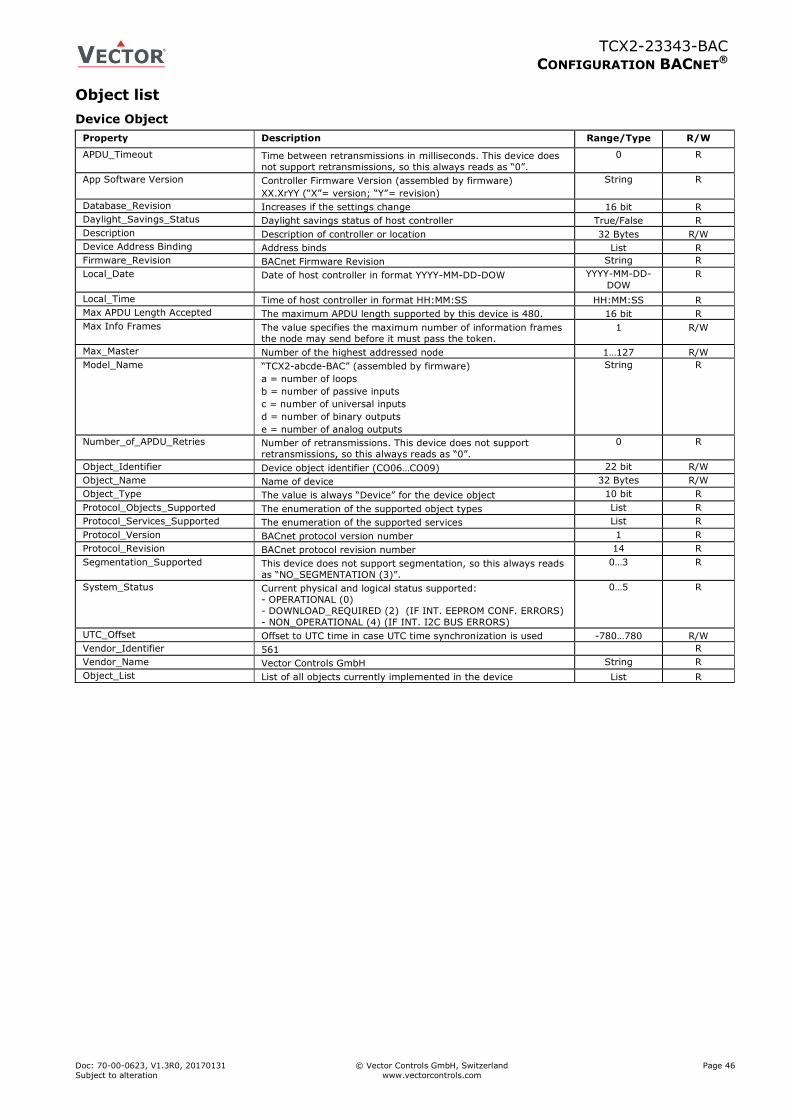
TCX2-23343-BAC
CONFIGURATION BACNET®
Doc: 70-00-0623, V1.3R0, 20170131 © Vector Controls GmbH, Switzerland Page 46
Subject to alteration www.vectorcontrols.com
Object list
Device Object
Property Description Range/Type R/W
APDU_Timeout Time between retransmissions in milliseconds. This device does not support retransmissions, so this always reads as “0”.
0 R
App Software Version Controller Firmware Version (assembled by firmware)
XX.XrYY (“X”= version; “Y”= revision)
String R
Database_Revision Increases if the settings change 16 bit R
Daylight_Savings_Status Daylight savings status of host controller True/False R
Description Description of controller or location 32 Bytes R/W
Device Address Binding Address binds List R
Firmware_Revision BACnet Firmware Revision String R
Local_Date Date of host controller in format YYYY-MM-DD-DOW YYYY-MM-DD-
DOW
R
Local_Time Time of host controller in format HH:MM:SS HH:MM:SS R
Max APDU Length Accepted The maximum APDU length supported by this device is 480. 16 bit R
Max Info Frames The value specifies the maximum number of information frames the node may send before it must pass the token.
1 R/W
Max_Master Number of the highest addressed node 1…127 R/W
Model_Name “TCX2-abcde-BAC” (assembled by firmware)
a = number of loops
b = number of passive inputs
c = number of universal inputs
d = number of binary outputs
e = number of analog outputs
String R
Number_of_APDU_Retries Number of retransmissions. This device does not support retransmissions, so this always reads as “0”.
0 R
Object_Identifier Device object identifier (CO06…CO09) 22 bit R/W
Object_Name Name of device 32 Bytes R/W
Object_Type The value is always “Device” for the device object 10 bit R
Protocol_Objects_Supported The enumeration of the supported object types List R
Protocol_Services_Supported The enumeration of the supported services List R
Protocol_Version BACnet protocol version number 1 R
Protocol_Revision BACnet protocol revision number 14 R
Segmentation_Supported This device does not support segmentation, so this always reads as “NO_SEGMENTATION (3)”.
0…3 R
System_Status Current physical and logical status supported: - OPERATIONAL (0)
- DOWNLOAD_REQUIRED (2) (IF INT. EEPROM CONF. ERRORS)
- NON_OPERATIONAL (4) (IF INT. I2C BUS ERRORS)
0…5 R
UTC_Offset Offset to UTC time in case UTC time synchronization is used -780…780 R/W
Vendor_Identifier 561 R
Vendor_Name Vector Controls GmbH String R
Object_List List of all objects currently implemented in the device List R
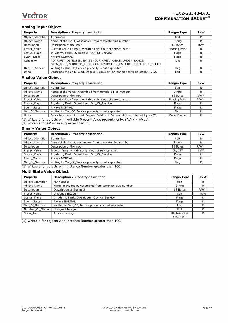
TCX2-23343-BAC
CONFIGURATION BACNET®
Doc: 70-00-0623, V1.3R0, 20170131 © Vector Controls GmbH, Switzerland Page 47
Subject to alteration www.vectorcontrols.com
Analog Input Object
Property Description / Property description Range/Type R/W
Object_Identifier AI number 8bit R
Object_Name Name of the input, Assembled from template plus number String R
Description Description of the input 16 Bytes R/W
Preset_Value Current value of input, writable only if out of service is set Floating Point R
Status_Flags In_Alarm, Fault, Overridden, Out_Of_Service Flags R
Event_State Always NORMAL Flags R
Reliability NO_FAULT_DETECTED, NO_SENSOR, OVER_RANGE, UNDER_RANGE,
OPEN_LOOP, SHORTED_LOOP, COMMUNICATION_FAILURE, UNRELIABLE_OTHER
List R
Out_Of_Service Writing to Out_Of_Service property is not supported Flag R
Units Describes the units used. Degree Celsius or Fahrenheit has to be set by MV02. 8bit R
Analog Value Object
Property Description / Property description Range/Type R/W
Object_Identifier AV number 8bit R
Object_Name Name of the value, Assembled from template plus number String R
Description Description of the input 16 Bytes R/W(1)
Preset_Value Current value of input, writable only if out of service is set Floating Point R/W(2)
Status_Flags In_Alarm, Fault, Overridden, Out_Of_Service Flags R
Event_State Always NORMAL Flags R
Out_Of_Service Writing to Out_Of_Service property is not supported Flag R
Units Describes the units used. Degree Celsius or Fahrenheit has to be set by MV02. Coded Value R
(1) Writable for objects with writable Present Value property only. (AVxx > AV11) (2) Writable for AV indexes greater than 11.
Binary Value Object
Property Description / Property description Range/Type R/W
Object_Identifier BV number 8bit R
Object_Name Name of the input, Assembled from template plus number String R
Description Description of the input 16 Bytes R/W(1)
Preset_Value True or False, writable only if out of service is set ON, OFF R/W
Status_Flags In_Alarm, Fault, Overridden, Out_Of_Service Flags R
Event_State Always NORMAL Flags R
Out_Of_Service Writing to Out_Of_Service property is not supported Flag R
(1) Writable for objects with Instance Number greater than 100.
Multi State Value Object
Property Description / Property description Range/Type R/W
Object_Identifier MV number 8bit R
Object_Name Name of the input, Assembled from template plus number String R
Description Description of the input 16 Bytes R/W(1)
Preset_Value Unsigned Integer 8bit R/W
Status_Flags In_Alarm, Fault, Overridden, Out_Of_Service Flags R
Event_State Always NORMAL Flags R
Out_Of_Service Writing to Out_Of_Service property is not supported Flag R
Number_Of_States Unsigned Integer 8bit R
State_Text Array of strings 8bytes/state
maximum
R
(1) Writable for objects with Instance Number greater than 100.
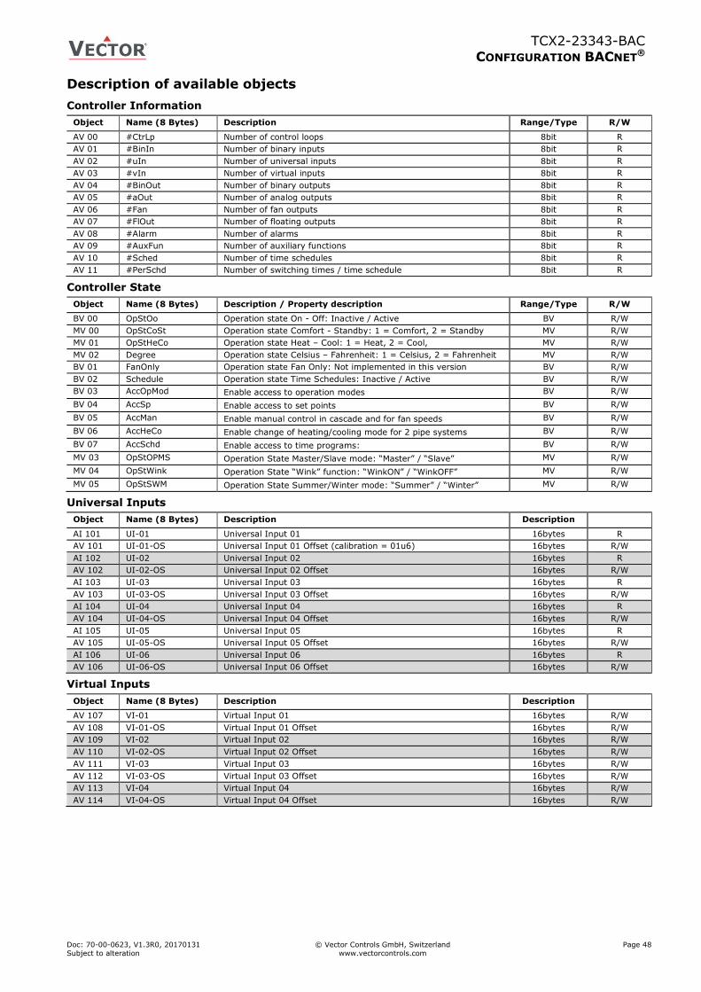
TCX2-23343-BAC
CONFIGURATION BACNET®
Doc: 70-00-0623, V1.3R0, 20170131 © Vector Controls GmbH, Switzerland Page 48
Subject to alteration www.vectorcontrols.com
Description of available objects
Controller Information
Object Name (8 Bytes) Description Range/Type R/W
AV 00 #CtrLp Number of control loops 8bit R
AV 01 #BinIn Number of binary inputs 8bit R
AV 02 #uIn Number of universal inputs 8bit R
AV 03 #vIn Number of virtual inputs 8bit R
AV 04 #BinOut Number of binary outputs 8bit R
AV 05 #aOut Number of analog outputs 8bit R
AV 06 #Fan Number of fan outputs 8bit R
AV 07 #FlOut Number of floating outputs 8bit R
AV 08 #Alarm Number of alarms 8bit R
AV 09 #AuxFun Number of auxiliary functions 8bit R
AV 10 #Sched Number of time schedules 8bit R
AV 11 #PerSchd Number of switching times / time schedule 8bit R
Controller State
Object Name (8 Bytes) Description / Property description Range/Type R/W
BV 00 OpStOo Operation state On - Off: Inactive / Active BV R/W
MV 00 OpStCoSt Operation state Comfort - Standby: 1 = Comfort, 2 = Standby MV R/W
MV 01 OpStHeCo Operation state Heat – Cool: 1 = Heat, 2 = Cool, MV R/W
MV 02 Degree Operation state Celsius – Fahrenheit: 1 = Celsius, 2 = Fahrenheit MV R/W
BV 01 FanOnly Operation state Fan Only: Not implemented in this version BV R/W
BV 02 Schedule Operation state Time Schedules: Inactive / Active BV R/W
BV 03 AccOpMod Enable access to operation modes BV R/W
BV 04 AccSp Enable access to set points BV R/W
BV 05 AccMan Enable manual control in cascade and for fan speeds BV R/W
BV 06 AccHeCo Enable change of heating/cooling mode for 2 pipe systems BV R/W
BV 07 AccSchd Enable access to time programs: BV R/W
MV 03 OpStOPMS Operation State Master/Slave mode: “Master” / “Slave” MV R/W
MV 04 OpStWink Operation State “Wink” function: “WinkON” / “WinkOFF” MV R/W
MV 05 OpStSWM Operation State Summer/Winter mode: “Summer” / “Winter” MV R/W
Universal Inputs
Object Name (8 Bytes) Description Description
AI 101 UI-01 Universal Input 01 16bytes R
AV 101 UI-01-OS Universal Input 01 Offset (calibration = 01u6) 16bytes R/W
AI 102 UI-02 Universal Input 02 16bytes R
AV 102 UI-02-OS Universal Input 02 Offset 16bytes R/W
AI 103 UI-03 Universal Input 03 16bytes R
AV 103 UI-03-OS Universal Input 03 Offset 16bytes R/W
AI 104 UI-04 Universal Input 04 16bytes R
AV 104 UI-04-OS Universal Input 04 Offset 16bytes R/W
AI 105 UI-05 Universal Input 05 16bytes R
AV 105 UI-05-OS Universal Input 05 Offset 16bytes R/W
AI 106 UI-06 Universal Input 06 16bytes R
AV 106 UI-06-OS Universal Input 06 Offset 16bytes R/W
Virtual Inputs
Object Name (8 Bytes) Description Description
AV 107 VI-01 Virtual Input 01 16bytes R/W
AV 108 VI-01-OS Virtual Input 01 Offset 16bytes R/W
AV 109 VI-02 Virtual Input 02 16bytes R/W
AV 110 VI-02-OS Virtual Input 02 Offset 16bytes R/W
AV 111 VI-03 Virtual Input 03 16bytes R/W
AV 112 VI-03-OS Virtual Input 03 Offset 16bytes R/W
AV 113 VI-04 Virtual Input 04 16bytes R/W
AV 114 VI-04-OS Virtual Input 04 Offset 16bytes R/W
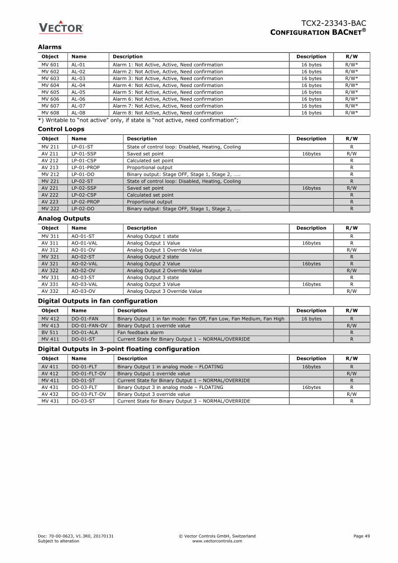
TCX2-23343-BAC
CONFIGURATION BACNET®
Doc: 70-00-0623, V1.3R0, 20170131 © Vector Controls GmbH, Switzerland Page 49
Subject to alteration www.vectorcontrols.com
Alarms
Object Name Description Description R/W
MV 601 AL-01 Alarm 1: Not Active, Active, Need confirmation 16 bytes R/W*
MV 602 AL-02 Alarm 2: Not Active, Active, Need confirmation 16 bytes R/W*
MV 603 AL-03 Alarm 3: Not Active, Active, Need confirmation 16 bytes R/W*
MV 604 AL-04 Alarm 4: Not Active, Active, Need confirmation 16 bytes R/W*
MV 605 AL-05 Alarm 5: Not Active, Active, Need confirmation 16 bytes R/W*
MV 606 AL-06 Alarm 6: Not Active, Active, Need confirmation 16 bytes R/W*
MV 607 AL-07 Alarm 7: Not Active, Active, Need confirmation 16 bytes R/W*
MV 608 AL-08 Alarm 8: Not Active, Active, Need confirmation 16 bytes R/W*
*) Writable to “not active” only, if state is “not active, need confirmation”;
Control Loops
Object Name Description Description R/W
MV 211 LP-01-ST State of control loop: Disabled, Heating, Cooling R
AV 211 LP-01-SSP Saved set point 16bytes R/W
AV 212 LP-01-CSP Calculated set point R
AV 213 LP-01-PROP Proportional output R
MV 212 LP-01-DO Binary output: Stage OFF, Stage 1, Stage 2, ….. R
MV 221 LP-02-ST State of control loop: Disabled, Heating, Cooling R
AV 221 LP-02-SSP Saved set point 16bytes R/W
AV 222 LP-02-CSP Calculated set point R
AV 223 LP-02-PROP Proportional output R
MV 222 LP-02-DO Binary output: Stage OFF, Stage 1, Stage 2, ….. R
Analog Outputs
Object Name Description Description R/W
MV 311 AO-01-ST Analog Output 1 state R
AV 311 AO-01-VAL Analog Output 1 Value 16bytes R
AV 312 AO-01-OV Analog Output 1 Override Value R/W
MV 321 AO-02-ST Analog Output 2 state R
AV 321 AO-02-VAL Analog Output 2 Value 16bytes R
AV 322 AO-02-OV Analog Output 2 Override Value R/W
MV 331 AO-03-ST Analog Output 3 state R
AV 331 AO-03-VAL Analog Output 3 Value 16bytes R
AV 332 AO-03-OV Analog Output 3 Override Value R/W
Digital Outputs in fan configuration
Object Name Description Description R/W
MV 412 DO-01-FAN Binary Output 1 in fan mode: Fan Off, Fan Low, Fan Medium, Fan High 16 bytes R
MV 413 DO-01-FAN-OV Binary Output 1 override value R/W
BV 511 DO-01-ALA Fan feedback alarm R
MV 411 DO-01-ST Current State for Binary Output 1 – NORMAL/OVERRIDE R
Digital Outputs in 3-point floating configuration
Object Name Description Description R/W
AV 411 DO-01-FLT Binary Output 1 in analog mode – FLOATING 16bytes R
AV 412 DO-01-FLT-OV Binary Output 1 override value R/W
MV 411 DO-01-ST Current State for Binary Output 1 – NORMAL/OVERRIDE R
AV 431 DO-03-FLT Binary Output 3 in analog mode – FLOATING 16bytes R
AV 432 DO-03-FLT-OV Binary Output 3 override value R/W
MV 431 DO-03-ST Current State for Binary Output 3 – NORMAL/OVERRIDE R
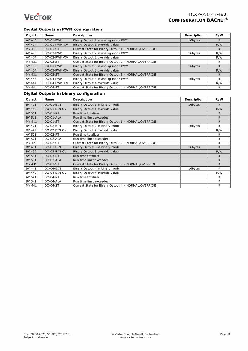
TCX2-23343-BAC
CONFIGURATION BACNET®
Doc: 70-00-0623, V1.3R0, 20170131 © Vector Controls GmbH, Switzerland Page 50
Subject to alteration www.vectorcontrols.com
Digital Outputs in PWM configuration
Object Name Description Description R/W
AV 413 DO-01-PWM Binary Output 1 in analog mode PWM 16bytes R
AV 414 DO-01-PWM-OV Binary Output 1 override value R/W
MV 411 DO-01-ST Current State for Binary Output 1 – NORMAL/OVERRIDE R
AV 423 DO-02-PWM Binary Output 2 in analog mode PWM 16bytes R/W
AV 424 DO-02-PWM-OV Binary Output 2 override value R/W
MV 421 DO-02-ST Current State for Binary Output 2 – NORMAL/OVERRIDE R
AV 433 DO-03-PWM Binary Output 3 in analog mode PWM 16bytes R
AV 434 DO-03-PWM-OV Binary Output 3 override value R/W
MV 431 DO-03-ST Current State for Binary Output 3 – NORMAL/OVERRIDE R
AV 443 DO-04-PWM Binary Output 4 in analog mode PWM 16bytes R
AV 444 DO-04-PWM-OV Binary Output 4 override value R/W
MV 441 DO-04-ST Current State for Binary Output 4 – NORMAL/OVERRIDE R
Digital Outputs in binary configuration
Object Name Description Description R/W
BV 411 DO-01-BIN Binary Output 1 in binary mode 16bytes R
BV 412 DO-01-BIN-OV Binary Output 1 override value R/W
AV 511 DO-01-RT Run time totalizer R
BV 511 DO-01-ALA Run time limit exceeded R
MV 411 DO-01-ST Current State for Binary Output 1 – NORMAL/OVERRIDE R
BV 421 DO-02-BIN Binary Output 2 in binary mode 16bytes R
BV 422 DO-02-BIN-OV Binary Output 2 override value R/W
AV 521 DO-02-RT Run time totalizer R
BV 521 DO-02-ALA Run time limit exceeded R
MV 421 DO-02-ST Current State for Binary Output 2 – NORMAL/OVERRIDE R
BV 431 DO-03-BIN Binary Output 3 in binary mode 16bytes R
BV 432 DO-03-BIN-OV Binary Output 3 override value R/W
AV 531 DO-03-RT Run time totalizer R
BV 531 DO-03-ALA Run time limit exceeded R
MV 431 DO-03-ST Current State for Binary Output 3 – NORMAL/OVERRIDE R
BV 441 DO-04-BIN Binary Output 4 in binary mode 16bytes R
BV 442 DO-04-BIN-OV Binary Output 4 override value R/W
AV 541 DO-04-RT Run time totalizer R
BV 541 DO-04-ALA Run time limit exceeded R
MV 441 DO-04-ST Current State for Binary Output 4 – NORMAL/OVERRIDE R