Embed Size (px)
Citation preview

TCS
No. 238-713-01JMarch 2018
Temperature Concentrator System™Multi-Channel Transmitter
Customer SupportMoore Industries is recognized as the industry leader in delivering top quality to its customers in products and services. We perform a sequence of stringent quality assurance checks on every unit we ship. If any Moore Industries product fails to perform up to rated specifications, call us for help. Our highly skilled staff of trained technicians and engineers pride themselves on their ability to provide timely, accurate, and practical answers to your process instrumentation questions. Our headquarters and other facilities phone numbers are listed below. There are several pieces of information that can be gathered before you call the factory that will help our staff get the answers you need in the shortest time possible. For fastest service, gather the complete model and serial number(s) of the problem unit(s) and the job number of the original sale.
www.miinet.com
Demand Moore Reliability
Locations
World Headquarters Europe Australia
16650 Schoenborn StreetNorth Hills, California91343-6196, U.S.A.Tel: (818) 894-7111Fax: (818) 891-2816E-mail: [email protected] FREE: 1-800-999-2900www.miinet.com
1 Lloyds Court, Manor Royal, CrawleyW. Sussex RH10-9QUUnited KingdomTel: 01293 514488Fax: 01293 536852FREE PHONE: 0800 [email protected]/uk
Sydney, NSW3/1 Resolution DriveCaringbah, New South Wales 2229AustraliaTel: (02) 8536-7200Fax: (02) [email protected]/au
China Guido Gezellestraat 106 BE-2630 AartselaarBelgiumTel: 03/448.10.18Fax: 03/[email protected]: www.miinet.com/dbeFrench: www.miinet.com/fbe
Perth, WA6/46 Angove StreetNorth Perth, Western Australia 6006AustraliaTel: (08) 9228-4435Fax: (08) [email protected]/au
Room 102, No. 101, Lane 1058, Xinzhen Street, Xinqiao Town, Songjiang District,Shanghai, 201612, P. R. ChinaTel: 86-21 62491499Fax: 86-21 62490635E-mail: [email protected]/cn
Burg Meslaan 984003 CD TielThe NetherlandsTel: (0)344-617971Fax: (0)[email protected]/nl
www.miinet.com Moore Industries-International, Inc.
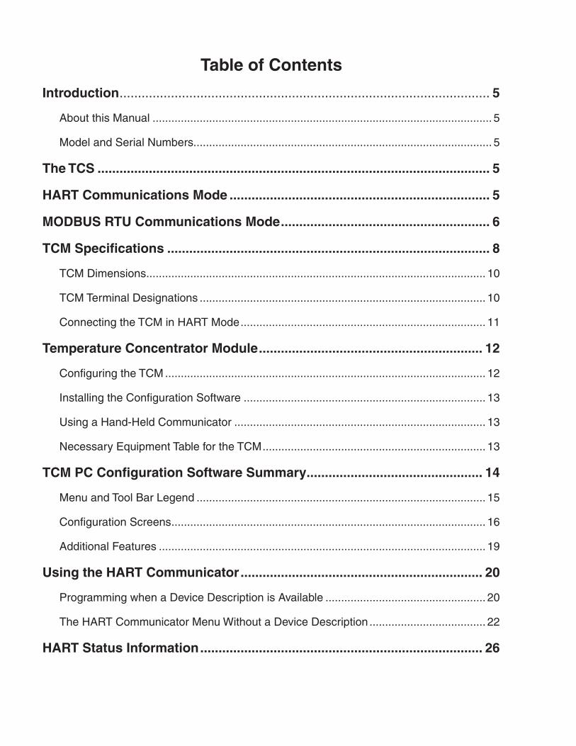
Table of Contents
Introduction ..................................................................................................... 5
About this Manual ............................................................................................................ 5
Model and Serial Numbers............................................................................................... 5
The TCS ........................................................................................................... 5
HART Communications Mode ....................................................................... 5
MODBUS RTU Communications Mode ......................................................... 6
TCM Specifications ........................................................................................ 8
TCM Dimensions ............................................................................................................ 10
TCM Terminal Designations ........................................................................................... 10
Connecting the TCM in HART Mode .............................................................................. 11
Temperature Concentrator Module ............................................................. 12
Configuring the TCM ...................................................................................................... 12
Installing the Configuration Software ............................................................................. 13
Using a Hand-Held Communicator ................................................................................ 13
Necessary Equipment Table for the TCM ....................................................................... 13
TCM PC Configuration Software Summary ................................................ 14
Menu and Tool Bar Legend ............................................................................................ 15
Configuration Screens .................................................................................................... 16
Additional Features ........................................................................................................ 19
Using the HART Communicator .................................................................. 20
Programming when a Device Description is Available ................................................... 20
The HART Communicator Menu Without a Device Description ..................................... 22
HART Status Information ............................................................................. 26
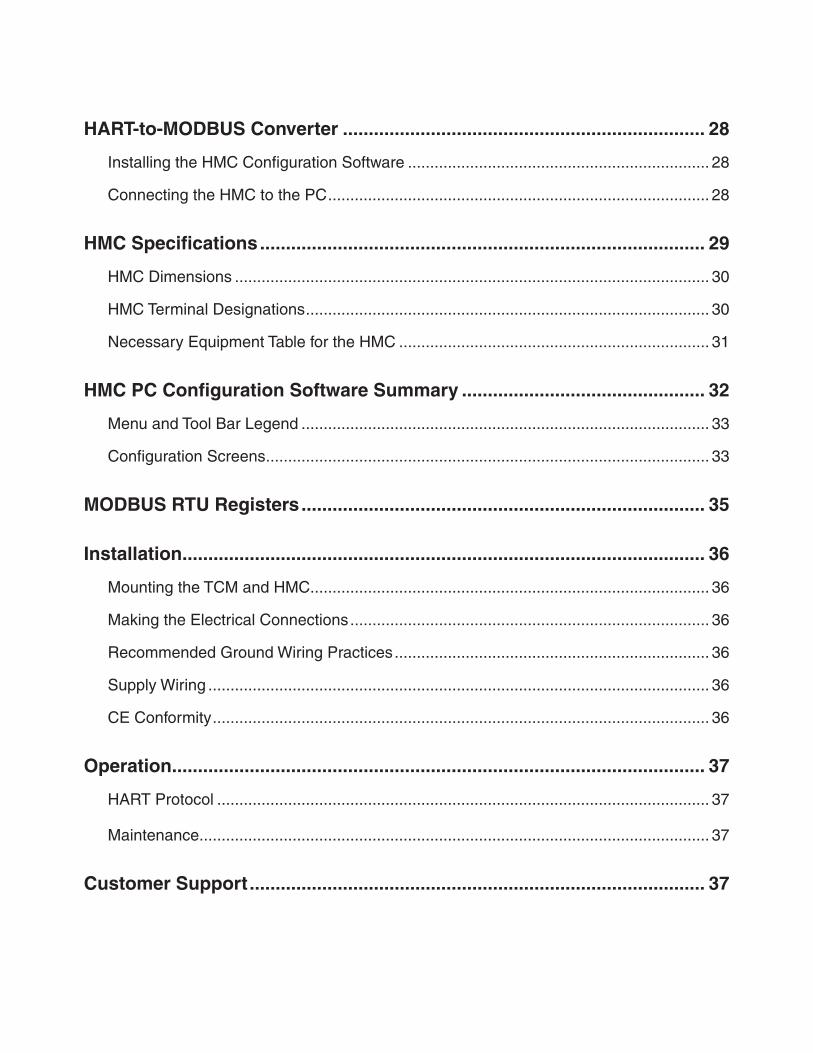
HART-to-MODBUS Converter ...................................................................... 28
Installing the HMC Configuration Software .................................................................... 28
Connecting the HMC to the PC ...................................................................................... 28
HMC Specifications ...................................................................................... 29
HMC Dimensions ........................................................................................................... 30
HMC Terminal Designations ........................................................................................... 30
Necessary Equipment Table for the HMC ...................................................................... 31
HMC PC Configuration Software Summary ............................................... 32
Menu and Tool Bar Legend ............................................................................................ 33
Configuration Screens .................................................................................................... 33
MODBUS RTU Registers .............................................................................. 35
Installation ..................................................................................................... 36
Mounting the TCM and HMC .......................................................................................... 36
Making the Electrical Connections ................................................................................. 36
Recommended Ground Wiring Practices ....................................................................... 36
Supply Wiring ................................................................................................................. 36
CE Conformity ................................................................................................................ 36
Operation ....................................................................................................... 37
HART Protocol ............................................................................................................... 37
Maintenance ................................................................................................................... 37
Customer Support ........................................................................................ 37
Installation in Hazardous Locations ........................................................... 38
Specific conditions of Use ........................................................................... 38
IECEx Installation ........................................................................................ 41
Appendix A:TCS/Stahl I.S. Barrier Configuration ...................................... 43
Appendix B:TCS/GMI I.S. Barrier Configuration ........................................ 44
The Interface Solution Experts 5
TCSTemperature Concentrator System™
Multi-Channel Transmitter
IntroductionThis manual for Moore Industries’ TCS Temperature Concentrator System™ contains all of the information needed to configure, install, operate and maintain this product.
About this ManualPay particular attention wherever you see a “Note”, “Caution” or “WARNING ”.
Note– Information that is helpful for a procedure, condition or operation of the unit.
Caution– Hazardous procedure or condition that could damage or destroy the unit.
WARNING– Hazardous procedure or condition that could injure the operator.
Model and Serial NumbersMoore Industries uses the model and serial numbers of our instruments to track information regarding each unit that we sell and service. If a problem occurs with your instrument, check for a tag affixed to the unit listing these numbers. Supply the Customer Support representative with this information when calling.
To obtain the TCM’s serial number, you may read it from the label. You may also use any device that can read the TCM’s Device Description (i.e. portable DD shell) or use the TCM Intelligent PC Configuration Software program.
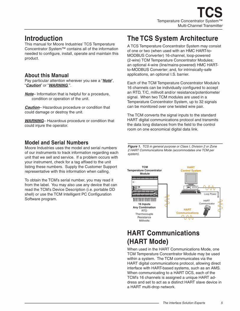
The TCS System Architecture A TCS Temperature Concentrator System may consist of one or two (when used with an HMC HART-to-MODBUS Converter) 16-channel, loop-powered (2-wire) TCM Temperature Concentrator Modules; an optional 4-wire (line/mains-powered) HMC HART-to-MODBUS Converter; and, for intrinsically-safe applications, an optional I.S. barrier.
Each of the TCM Temperature Concentrator Module’s 16 channels can be individually configured to accept an RTD, T/C, millivolt and/or resistance/potentiometer signal. When two TCM modules are used in a Temperature Concentrator System, up to 32 signals can be monitored over one twisted wire pair.
The TCM converts the signal inputs to the standard HART digital communications protocol and transmits the data long distances from the field to the control room on one economical digital data link.
HART Communications (HART Mode)When used in the HART Communications Mode, one TCM Temperature Concentrator Module may be used within a system. The TCM communicates via the HART digital communications protocol, allowing direct interface with HART-based systems, such as an AMS. When communicating to a HART DCS, each of the TCM’s 16 channels is assigned a unique HART ad-dress and set to act as a distinct HART slave device in a HART multi-drop network.
Figure 1. TCS in general purpose or Class I, Division 2 or Zone 2 HART Communications Mode (accommodates one TCM per system).
HARTCommunications
HARTControl System
16 InputsAny Combination
RTDThermocouple
ResistanceMillivolts
STATUS
TEMPERATURECONCENTRATORMODULE
COM
TCMTemperature Concentrator
Module
Loop Power
HART Communicator
6 The Interface Solution Experts
TCSTemperature Concentrator System™Multi-Channel Transmitter
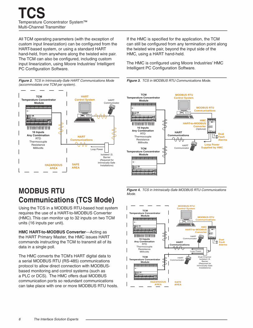
Figure 2. TCS in Intrinsically-Safe HART Communications Mode (accommodates one TCM per system).
All TCM operating parameters (with the exception of custom input linearization) can be configured from the HART-based system, or using a standard HART hand-held, from anywhere along the twisted wire pair. The TCM can also be configured, including custom input linearization, using Moore Industries’ Intelligent PC Configuration Software.
HAZARDOUSAREA
SAFEAREA
Isolated I.S.Barrier
(Required forIntrinsically-Safe
Installations)
HARTCommunications
HARTControl System
16 InputsAny Combination
RTDThermocouple
ResistanceMillivolts
STATUS
TEMPERATURECONCENTRATORMODULE
COM
TCMTemperature Concentrator
Module
Loop Power
HART Communicator
Figure 3. TCS in MODBUS RTU Communications Mode.
MODBUS RTU Communications (TCS Mode) Using the TCS in a MODBUS RTU-based host system requires the use of a HART-to-MODBUS Converter (HMC). This can monitor up to 32 inputs on two TCM units (16 inputs per unit).
HMC HART-to-MODBUS Converter—Acting as the HART Primary Master, the HMC issues HART commands instructing the TCM to transmit all of its data in a single poll.
The HMC converts the TCM’s HART digital data to a serial MODBUS RTU (RS-485) communications protocol to allow direct connection with MODBUS-based monitoring and control systems (such as a PLC or DCS). The HMC offers dual MODBUS communication ports so redundant communications can take place with one or more MODBUS RTU hosts.
If the HMC is specified for the application, the TCM can still be configured from any termination point along the twisted wire pair, beyond the input side of the HMC, using a HART hand-held.
The HMC is configured using Moore Industries’ HMC Intelligent PC Configuration Software.
HMCHART-to-MODBUS
Converter(Optional)
HARTCommunications
INPUT
READY
FAULT 1
FAULT 2
HARTMODBUSCONVERTER
COM
MODBUS RTUCommunications
MODBUS RTUControl System
Loop PowerSupplied by HMC
DualFaultAlarms
16 InputsAny Combination
RTDThermocouple
ResistanceMillivolts
TCMTemperature Concentrator
Module
STATUS
TEMPERATURECONCENTRATORMODULE
COM
STATUS
TEMPERATURECONCENTRATORMODULE
COM
TCMTemperature Concentrator
Module
HART Communicator
Figure 4. TCS in Intrinsically-Safe MODBUS RTU Communications Mode.
HAZARDOUSAREA
SAFEAREA
Dual-Channel Isolated I.S.
Barrier(Required for
Intrinsically-Safe Installations)
HMCHART-to-MODBUS
Converter
HARTCommunications
INPUT
READY
FAULT 1
FAULT 2
HARTMODBUSCONVERTER
COM
MODBUS RTUCommunications
MODBUS RTUControl System
DualFaultAlarms
16 InputsAny Combination
RTDThermocouple
ResistanceMillivolts
TCMTemperature Concentrator
Module
STATUS
TEMPERATURECONCENTRATORMODULE
COM
STATUS
TEMPERATURECONCENTRATORMODULE
COM
TCMTemperature Concentrator
Module
Loop Power
HART Communicator
HART Communicator
The Interface Solution Experts 7
TCSTemperature Concentrator System™
Multi-Channel Transmitter
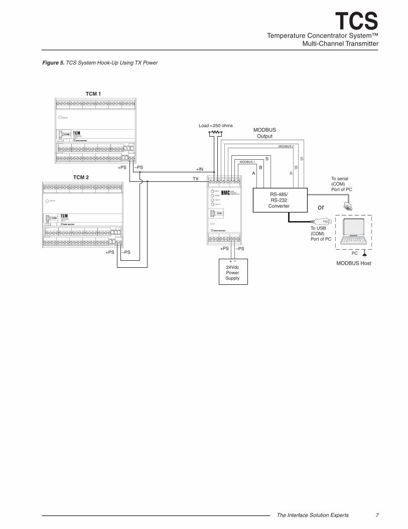
Figure 5. TCS System Hook-Up Using TX Power
TCM 1
TCM 2
+PS –PS
+PS –PS
Load = 250 ohms
TX
+IN
INPUT
READY
FAULT 1
FAULT 2
HARTMODBUSCONVERTER
COM
STATUS
TEMPERATURECONCENTRATORMODULE
COM
STATUS
TEMPERATURECONCENTRATORMODULE
COM
+–
24VdcPowerSupply
+PS –PS
MODBUSOutput
AB
S
AB
S
To USB (COM)Port of PC
To serial (COM)Port of PC
or
MODBUS Host
RS-485/RS-232
Converter
MODBUS 2
MODBUS 1
PC
8 The Interface Solution Experts
TCSTemperature Concentrator System™Multi-Channel Transmitter
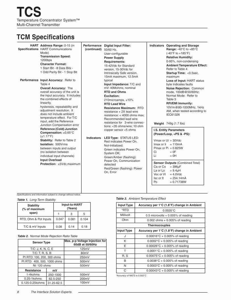
TCM Specifications
Specifications and information subject to change without notice.
Address Range: 0-15 (in HART Communications Mode) Transmission Speed: 1200bpsCharacter Format: 1 Start Bit - 8 Data Bits - 1 Odd Parity Bit - 1 Stop Bit
Input Accuracy: Refer to Table 4Overall Accuracy: The overall accuracy of the unit is the input accuracy. It includes the combined effects of linearity, hysteresis, repeatability and adjustment resolution. It does not include ambient temperature effect. For T/C input, add the Reference Junction Compensation errorReference (Cold) Junction Compensation: ±0.65°C (±1.17°F)Stability: Refer to Table 2Isolation: 500Vrms between inputs and output (no isolation between individual input channels)Input OverloadProtection: ±5Vdc,maximum
Digital Input Filter: 50/60 Hz, User-configurable Power Supply Requirements: 15-42Vdc for Standard version, 15-30Vdc for Intrinsically Safe version, 15mA maximum, 12.5mA typicalInput Impedance: T/C and mV: 40Mohms, nominalRTD and OhmsExcitation: 210microamps, ±10%RTD Lead Wire Resistance Maximum: RTD resistance + 2X lead wire resistance: < 4000 ohms max; Recommended lead wire resistance for 3-wire connec-tions: <35 ohms/wire; 10 ohm copper sensor <5 ohms
LED Type: STATUS LED: Red indicates Power On, Not-Initialized;Green indicates Power On, System OK;Green/Amber (flashing): Power On, Communication detectedRed/Green (flashing): Power On, Error
Operating and Storage Range: -40°C to +85°C (-40°F to +185°F)Relative Humidity: 0-95%, non-condensingAmbient Temperature Effect: Refer to Table 4Startup Time: <0.5sec, maximumLoss of Input: HART status byte indicates faultsNoise Rejection: Common mode, 100dB@50/60Hz; Normal Mode: Refer to Table 3RFI/EMI Immunity: 10V/m@80-1000MHz, 1kHz AM, when tested according to IEC61326
749g (1.7 lbs)
Table 1. Long-Term Stability Table 3. Ambient Temperature Effect
Input Type
*RTD Millivolt Ohm
0.0035°C 0.5 microvolts + 0.005% of reading 0.002 ohms + 0.005% of reading
*Accuracy of Ni672 is 0.002°C
Thermocouples
Accuracy per 1°C (1.8°F) change in Ambient
J K E T
R, S B N C
0.00016°C + 0.005% of reading 0.0002°C + 0.005% of reading 0.00026°C + 0.005% of reading 0.0001°C + 0.005% of reading 0.00075°C + 0.005% of reading 0.0038°C + 0.005% of reading 0.0003°C + 0.005% of reading 0.00043°C + 0.005% of reading
Accuracy per 1°C (1.8°F) change in AmbientInput Type
Table 2. Normal Mode Rejection Ratio Table
Sensor Type Max. p-p Voltage Injection for 60dB at 50/60Hz
125mV80mV250mV500mV500mV
500mV 200mV100mV
T/C: J, K, N, C, ET/C: T, R, S, B
Pt RTD: 100, 200, 300 ohmsPt RTD: 400, 500, 1000 ohms
Ni: 120 ohms mV
250-1000 62.5-250
31.25-62.5
Resistance1-4kohms
0.25-1kohms0.125-0.25kohms
RTD, Ohm & Pot Inputs
Input-to-HART (Years)
Stability (% of maximum
span) 1 3 5
0.047
0.08
0.081
0.14
0.104
0.18T/C & mV Inputs
I.S. Entity Parameters(Power/Loop, +PS & -PS):
Vmax or Ui = 30VdcImax or Ii = 110mAPmax or Pi = 0.825WCi = 0FLi = 0H
Sensor Outputs (Combined Total)Ca or Co = 396μFLa or Lo = 9.4μHVoc or Vt = 4.0VdcIsc or It = 254.14mAPo = 0.71738W
HART Specifications
Performance
Performance (continued)
Indicators
Indicators
Weight
The Interface Solution Experts 9
TCSTemperature Concentrator System™
Multi-Channel Transmitter
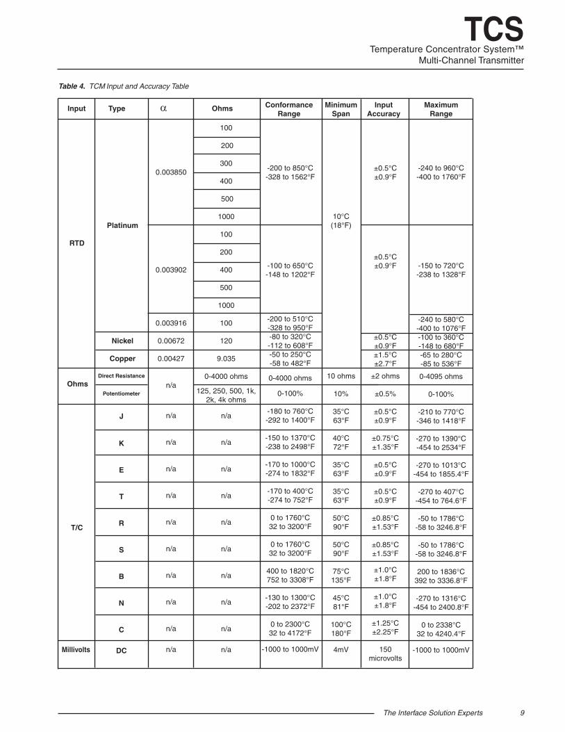
-200 to 850°C -328 to 1562°F
-100 to 650°C -148 to 1202°F
-200 to 510°C -328 to 950°F -80 to 320°C -112 to 608°F -50 to 250°C -58 to 482°F
0-4000 ohms
0-100%
-180 to 760°C -292 to 1400°F
-150 to 1370°C -238 to 2498°F
-170 to 1000°C -274 to 1832°F
-170 to 400°C -274 to 752°F
0 to 1760°C 32 to 3200°F
0 to 1760°C 32 to 3200°F
400 to 1820°C 752 to 3308°F
-130 to 1300°C -202 to 2372°F
0 to 2300°C 32 to 4172°F
-1000 to 1000mV
Table 4. TCM Input and Accuracy Table
100
200
300
400
500
1000
100
200
400
500
1000
100
120
9.035
0-4000 ohms
125, 250, 500, 1k, 2k, 4k ohms
n/a
n/a
n/a
n/a
n/a
n/a
n/a
n/a
n/a
n/a
-240 to 960°C -400 to 1760°F
-150 to 720°C -238 to 1328°F
-240 to 580°C -400 to 1076°F -100 to 360°C -148 to 680°F -65 to 280°C -85 to 536°F 0-4095 ohms
0-100%
-210 to 770°C -346 to 1418°F
-270 to 1390°C -454 to 2534°F
-270 to 1013°C
-454 to 1855.4°F
-270 to 407°C -454 to 764.6°F
-50 to 1786°C
-58 to 3246.8°F
-50 to 1786°C -58 to 3246.8°F
200 to 1836°C
392 to 3336.8°F
-270 to 1316°C -454 to 2400.8°F
0 to 2338°C
32 to 4240.4°F
-1000 to 1000mV
RTD
T/C
Direct Resistance
Potentiometer J
K E T R S B N C
DC
Input Type α Ohms Conformance Range
Minimum Span
Input Accuracy
Maximum Range
10°C (18°F)
10 ohms
10%
35°C 63°F
40°C 72°F
35°C 63°F
35°C 63°F
50°C 90°F
50°C 90°F
75°C 135°F
45°C 81°F
100°C 180°F
4mV
Ohms
Platinum
Nickel
Copper
0.003850
0.003902
0.003916
0.00672
0.00427
n/a
n/a
n/a
n/a
n/a
n/a
n/a
n/a
n/a
n/a
n/a
±0.5°C ±0.9°F
±0.5°C ±0.9°F
±0.5°C ±0.9°F ±1.5°C ±2.7°F
±2 ohms
±0.5%
±0.5°C ±0.9°F
±0.75°C ±1.35°F
±0.5°C ±0.9°F
±0.5°C ±0.9°F
±0.85°C ±1.53°F
±0.85°C ±1.53°F
±1.0°C ±1.8°F
±1.0°C ±1.8°F
±1.25°C ±2.25°F
150
microvoltsMillivolts
10 The Interface Solution Experts
TCSTemperature Concentrator System™Multi-Channel Transmitter
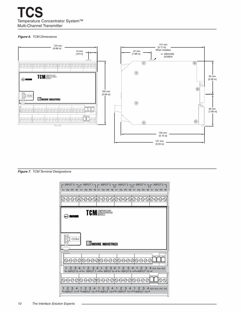
Figure 6. TCM Dimensions
Figure 7. TCM Terminal Designations
INPUT 1
31 2
INPUT 0
4 1 2 3 4
INPUT 3
31 2
INPUT 2
4 1 2 3 4
INPUT 5
31 2
INPUT 4
4 1 2 3 4
INPUT 6 21 4
INPUT 721 43
INPUT 821 43
INPUT 921 43
INPUT 1021 43 N/A N/A N/A
-PS+PS
INPUT 1121 43
INPUT 1221 43
INPUT 1321 43
INPUT 1421 43
INPUT 1521 43 N/A N/A
3
130 mm [5.15 in]
141 mm [5.55 in]
49 mm [1.96 in]
52 mm [2.06 in]
100 mm [3.94 in]
124 mm [4.88 in]
13 mm [.53 in]
131 mm [5.17 in]
When Installed47 mm [1.88 in] GROUND
SCREW
The Interface Solution Experts 11
TCSTemperature Concentrator System™
Multi-Channel Transmitter
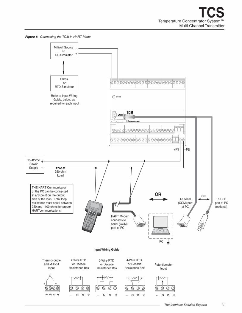
Figure 8. Connecting the TCM in HART Mode
TEMPERATURECONCENTRATORMODULE
+
–
15-42VdcPowerSupply
Millivolt Sourceor
T/C Simulator
_
+
Ohms or
RTD Simulator
+PS –PS
Refer to Input Wiring Guide, below, as
required for each input
PC
To serial(COM) port
of PC
To USB port of PC(optional)
2-Wire RTD or Decade
Resistance Box
3-Wire RTD or Decade
Resistance Box
4-Wire RTD or Decade
Resistance BoxPotentiometer
Input
31 2 4
+ –
Thermocoupleand Millivolt
Input
31 2 4 31 2 4 31 2 4
Input Wiring Guide
250 ohmLoad
HART Modemconnects to serial (COM)port of PC
THE HART Communicatoror the PC can be connected at any point on the output side of the loop. Total loop resistance must equal between 250 and 1100 ohms for proper HARTcommunications.
OR
STATUS
COM
31 2 4
OR
12 The Interface Solution Experts
TCSTemperature Concentrator System™Multi-Channel Transmitter
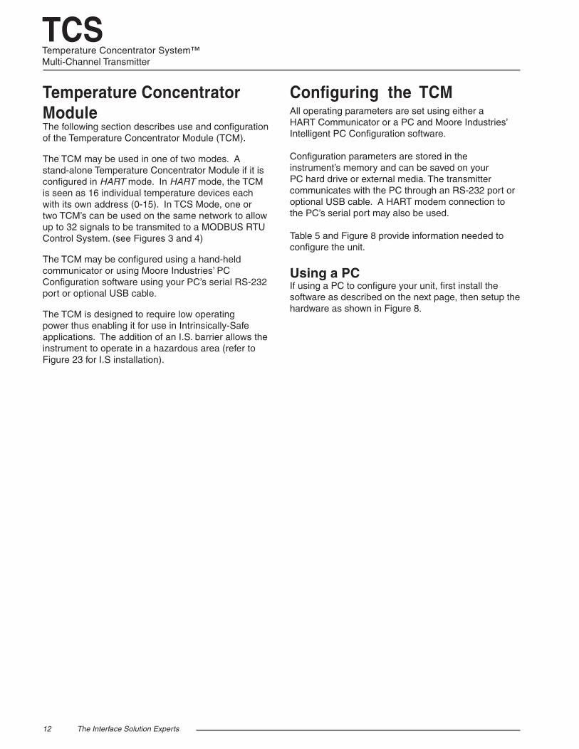
Temperature Concentrator ModuleThe following section describes use and configuration of the Temperature Concentrator Module (TCM).
The TCM may be used in one of two modes. A stand-alone Temperature Concentrator Module if it is configured in HART mode. In HART mode, the TCM is seen as 16 individual temperature devices each with its own address (0-15). In TCS Mode, one or two TCM’s can be used on the same network to allow up to 32 signals to be transmited to a MODBUS RTU Control System. (see Figures 3 and 4)
The TCM may be configured using a hand-held communicator or using Moore Industries’ PC Configuration software using your PC’s serial RS-232 port or optional USB cable.
The TCM is designed to require low operating power thus enabling it for use in Intrinsically-Safe applications. The addition of an I.S. barrier allows the instrument to operate in a hazardous area (refer to Figure 23 for I.S installation).
Configuring the TCMAll operating parameters are set using either a HART Communicator or a PC and Moore Industries’ Intelligent PC Configuration software. Configuration parameters are stored in the instrument’s memory and can be saved on your PC hard drive or external media. The transmitter communicates with the PC through an RS-232 port or optional USB cable. A HART modem connection to the PC’s serial port may also be used. Table 5 and Figure 8 provide information needed to configure the unit.
Using a PC If using a PC to configure your unit, first install the software as described on the next page, then setup the hardware as shown in Figure 8.

The Interface Solution Experts 13
TCSTemperature Concentrator System™
Multi-Channel Transmitter
Table 5. Necessary Equipment Table for the TCM
Installing the Configuration SoftwareRefer to Table 5 for the equipment needed.
1. Insert the Moore Industries Interface Solution PC Configuration Software CD into the CD drive of the PC. Access the CD and open the TCM PC Configuration Software folder.
2. Double-click the installation program located in the folder. Follow the prompts to correctly install the program.
Once the Configuration Program is installed on the PC, the TCM can be connected to equipment to simulate input and monitor output. You can then change the transmitter’s operating parameters.
It is not necessary to connect the transmitter to a PC to create configuration files using the PC Configuration Program. The program can be run without connecting a transmitter, and most parameters can be set without benefit of input from a sensor or transmitter.
This makes it easy to create a set of operating parameters, save them to external media, and download them to one or more transmitters at a later time.
The TCM must be connected to the PC in order to receive configuration parameters (via download) and save configuration parameters from the transmitter’s memory.
Connecting the TCM to the PCTo connect the TCM to the PC, you must establish a simple current loop for the transmitter by connecting a 15-42Vdc power supply, a 250 ohm resistor and the transmitter in series. See Table 1 for information on the necessary equipment. Refer to Figure 8 for installation.
Connect your instrument to the PC via the RS-232 serial port using the Moore Industries Interface Cable or optional USB cable listed in Table 1.
Using a Hand-Held CommunicatorA HART modem may also be used to connect your unit to the PC. Connect the RS-232 or optional USB cable end of the modem to the PC’s COM port, then connect the HART output end of the modem (two hook-up wires) across the transmitter or the load resistor. For installation, refer to Figure 8.
Variable Input Simulator for Thermocouple, RTD, Millivolt, Potentiometer, or Decade
Resistance Box Power Supply
Precision Load Resistor
Multimeter (optional)
Personal Computer (Required only if
using a PC for setup)
Moore Industries Communications Cable HART Modem Cable
(Required only if using a PC)
Moore Industries PC Configuration Software
(Required only if using a PC)
HART Communicator (Required only if NOT using a PC)
Variable; Accurate to ±0.05% of unit span 15-42Vdc 250 ohms, ±0.01% Accurate to ±0.025% of span; e.g., Fluke Model 87 Pentium-based PC, or equivalent with: CD Drive; 4Mb free RAM (8Mb recommended); 20Mb free disk space on hard drive Operating System: Microsoft Windows® XP, Vista 7 or 10, one serial port 1 (one) serial or USB port Part# 803-040-26 (for a 9-pin serial port) or 804-030-26 (for a USB port).
Moore Industries part number 803-048-26, or equivalent
Version 1.0 or greater, successfully installed to the hard drive
HART compliant communicator capable of running necessary device description files
Device Specifications
14 The Interface Solution Experts
TCSTemperature Concentrator System™Multi-Channel Transmitter
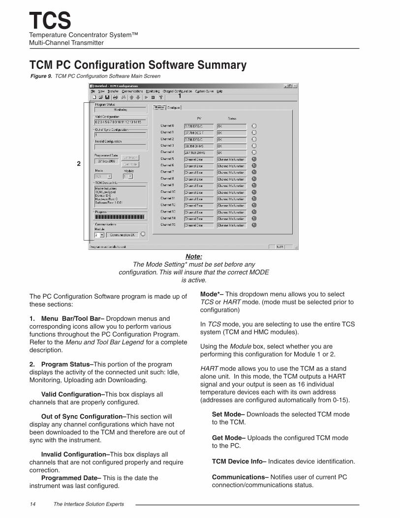
Figure 9. TCM PC Configuration Software Main Screen
TCM PC Configuration Software Summary
Note: The Mode Setting* must be set before any
configuration. This will insure that the correct MODE is active.
1
2
The PC Configuration Software program is made up of these sections:
1. Menu Bar/Tool Bar– Dropdown menus and corresponding icons allow you to perform various functions throughout the PC Configuration Program. Refer to the Menu and Tool Bar Legend for a complete description.
2. Program Status–This portion of the program displays the activity of the connected unit such: Idle, Monitoring, Uploading adn Downloading.
Valid Configuration–This box displays all channels that are properly configured.
Out of Sync Configuration–This section will display any channel configurations which have not been downloaded to the TCM and therefore are out of sync with the instrument.
Invalid Configuration–This box displays all channels that are not configured properly and require correction. Programmed Date– This is the date the instrument was last configured.
Mode*– This dropdown menu allows you to select TCS or HART mode. (mode must be selected prior to configuration)
In TCS mode, you are selecting to use the entire TCS system (TCM and HMC modules).
Using the Module box, select whether you are performing this configuration for Module 1 or 2.
HART mode allows you to use the TCM as a stand alone unit. In this mode, the TCM outputs a HART signal and your output is seen as 16 individual temperature devices each with its own address (addresses are configured automatically from 0-15).
Set Mode– Downloads the selected TCM mode to the TCM. Get Mode– Uploads the configured TCM mode to the PC. TCM Device Info– Indicates device identification. Communications– Notifies user of current PC connection/communications status.
The Interface Solution Experts 15
TCSTemperature Concentrator System™
Multi-Channel Transmitter
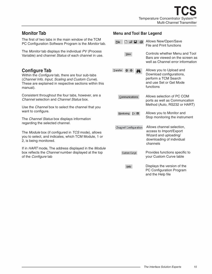
Menu and Tool Bar Legend
Allows New/Open/Save File and Print functions
Allows you to Upload and Download configurations, perform a TCM Search and use Set or Get Modefunctions
Allows selection of PC COM ports as well as Communcation Method (Auto, RS232 or HART)
Allows you to Monitor and Stop monitoring the instrument
Provides functions specific to your Custom Curve table
Controls whether Menu and Tool Bars are viewed on the screen aswell as Channel error information
Displays the version of the PC Configuration Programand the Help file
Allows channel selection, access to Import/Export Wizard and uploading/downloading of individualchannels
Monitor TabThe first of two tabs in the main window of the TCM PC Configuration Software Program is the Monitor tab.
The Monitor tab displays the individual PV (Process Variable) and channel Status of each channel in use.
Configure TabWithin the Configure tab, there are four sub-tabs (Channel Info, Input, Scaling and Custom Curve). These are explained in respective sections within this manual).
Consistent throughout the four tabs, however, are a Channel selection and Channel Status box.
Use the Channel box to select the channel that you want to configure.
The Channel Status box displays information regarding the selected channel.
The Module box (if configured in TCS mode), allows you to select, and indicates, which TCM Module, 1 or 2, is being monitored.
If in HART mode, The address displayed in the Module box reflects the Channel number displayed at the top of the Configure tab
16 The Interface Solution Experts
TCSTemperature Concentrator System™Multi-Channel Transmitter
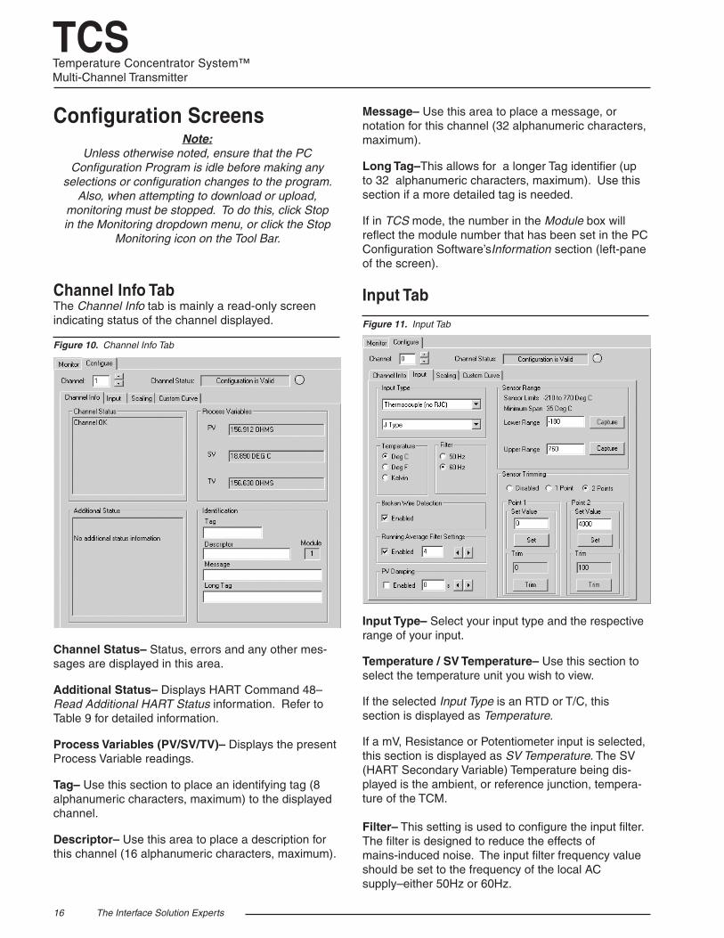
Input Tab
Input Type– Select your input type and the respective range of your input.
Temperature / SV Temperature– Use this section to select the temperature unit you wish to view.
If the selected Input Type is an RTD or T/C, this section is displayed as Temperature.
If a mV, Resistance or Potentiometer input is selected, this section is displayed as SV Temperature. The SV (HART Secondary Variable) Temperature being dis-played is the ambient, or reference junction, tempera-ture of the TCM. Filter– This setting is used to configure the input filter. The filter is designed to reduce the effects of mains-induced noise. The input filter frequency value should be set to the frequency of the local AC supply–either 50Hz or 60Hz.
Figure 11. Input Tab
Configuration ScreensNote:
Unless otherwise noted, ensure that the PC Configuration Program is idle before making any
selections or configuration changes to the program. Also, when attempting to download or upload,
monitoring must be stopped. To do this, click Stop in the Monitoring dropdown menu, or click the Stop
Monitoring icon on the Tool Bar.
Channel Info TabThe Channel Info tab is mainly a read-only screen indicating status of the channel displayed.
Channel Status– Status, errors and any other mes-sages are displayed in this area.
Additional Status– Displays HART Command 48–Read Additional HART Status information. Refer to Table 9 for detailed information.
Process Variables (PV/SV/TV)– Displays the present Process Variable readings.
Tag– Use this section to place an identifying tag (8 alphanumeric characters, maximum) to the displayed channel.
Descriptor– Use this area to place a description for this channel (16 alphanumeric characters, maximum).
Figure 10. Channel Info Tab
Message– Use this area to place a message, or notation for this channel (32 alphanumeric characters, maximum).
Long Tag–This allows for a longer Tag identifier (up to 32 alphanumeric characters, maximum). Use this section if a more detailed tag is needed.
If in TCS mode, the number in the Module box will reflect the module number that has been set in the PC Configuration Software’sInformation section (left-pane of the screen).
The Interface Solution Experts 17
TCSTemperature Concentrator System™
Multi-Channel Transmitter
Sensor Trimming– Sensor Trimming increases the measurement accuracy of your instrument by matching the reading of its actual input, to either a calibrated source or the device to which it is connected. This verifies that the input to the transmitter is being interpreted correctly.
You may trim any point between 0% and 100% along the scale. Note that one-point trimming applies an offset to the sensor reading, while two-point trimming applies both an offset and a gain.
Follow the steps below in order to perform sensor trimming.
1. Select either 1 Point (one-point trimming) or 2 Points (two-point trimming) by clicking the appropriate button. Each pair consists of Set Value and Trim fields.
2. Enter the values that require trimming into the Set Value field and click Set.
3. Apply the targeted signal to the input, wait until it settles, and click Trim to capture the measured value. If you chose 2 Points, repeat the step above for the second point.
Note: Once you have configured all parameters, download
to the unit by selecting Download in the Transfer dropdown menu located in the Menu Bar. Or, click
the button in the Tool Bar.
Broken Wire Detection– During operation, the TCM sends random microamp pulses through input wiring to check for broken wiring or a burned out sensor.
To utilize Broken Wire Detection, check the Enabled box. If a failure is detected, a message will appear in the TCM Status box.
Running Average Filter Settings– This function is for filtering the input signal. The TCM provides this filter with a user-selected range between 1 and 16. Factory default is 4.
Note: A higher Running Average Filter setting provides smoother output transitions; however, reduces
response time. Conversely, a lower setting provides a faster response time, but may seem more unstable.
PV Damping–PV Damping allows you to introduce a delay into the response of your unit in order to stop short-lived spikes from initiating faults and generating fault messages.
The configured damping period will determine the time response that the analog output will take to achieve a 63.21% change in output in response to a stepped input.
To enable PV Damping, select the Enabled button. Use the arrows to select a value between 1sec and 30sec.
Sensor Range– Allows you to set your upper and lower range values within the range chosen in the Input Type section.
The desired Upper and Lower Range settings can be entered via your PC keyboard or captured. To capture an input, follow the steps below.
1. Apply the desired Upper Range input and press the corresponding Capture button.
2. Next, apply the desired Lower Range input and press the corresponding Capture button.
18 The Interface Solution Experts
TCSTemperature Concentrator System™Multi-Channel Transmitter
Scaling Tab
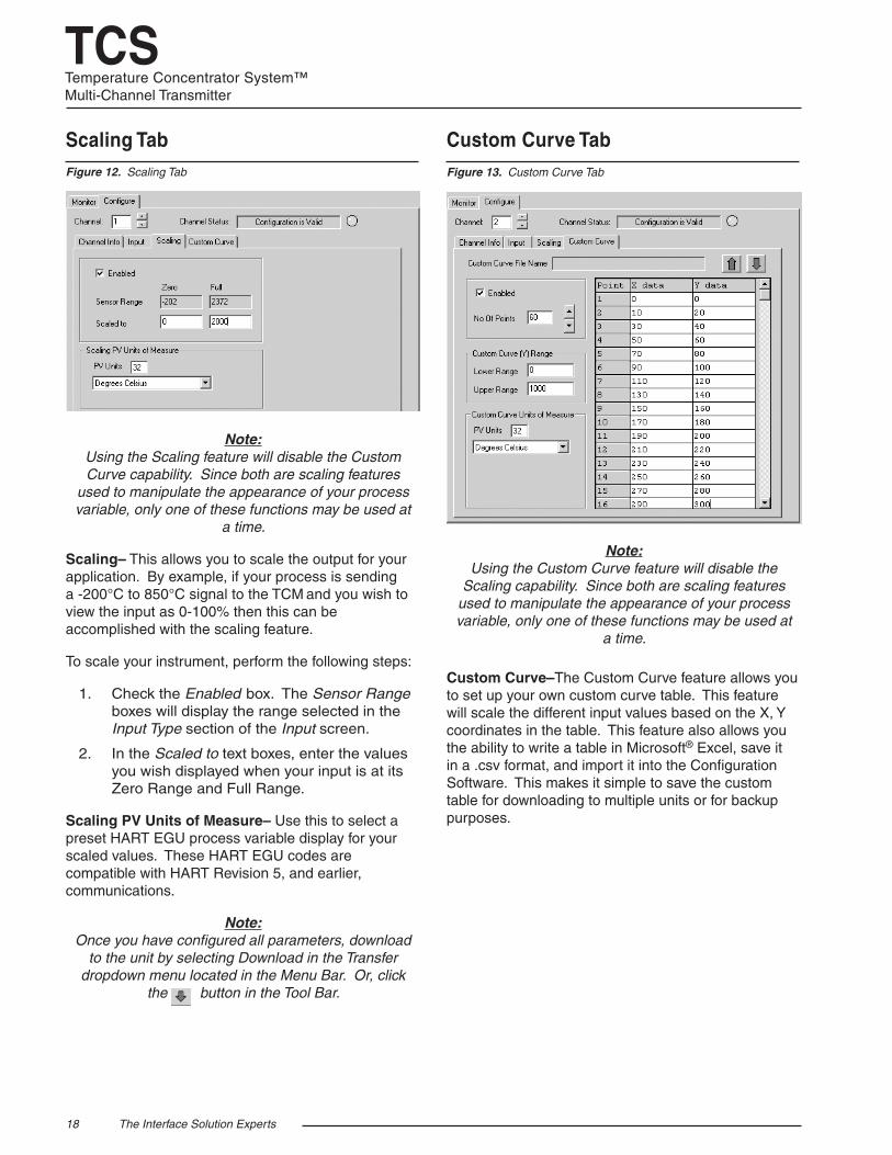
Note:
Using the Scaling feature will disable the Custom Curve capability. Since both are scaling features
used to manipulate the appearance of your process variable, only one of these functions may be used at
a time.
Scaling– This allows you to scale the output for your application. By example, if your process is sending a -200°C to 850°C signal to the TCM and you wish to view the input as 0-100% then this can be accomplished with the scaling feature.
To scale your instrument, perform the following steps:
1. Check the Enabled box. The Sensor Range boxes will display the range selected in the Input Type section of the Input screen.
2. In the Scaled to text boxes, enter the values you wish displayed when your input is at its Zero Range and Full Range.
Scaling PV Units of Measure– Use this to select a preset HART EGU process variable display for your scaled values. These HART EGU codes are compatible with HART Revision 5, and earlier, communications.
Note: Once you have configured all parameters, download
to the unit by selecting Download in the Transfer dropdown menu located in the Menu Bar. Or, click
the button in the Tool Bar.
Figure 12. Scaling Tab
Custom Curve Tab
Note: Using the Custom Curve feature will disable the
Scaling capability. Since both are scaling features used to manipulate the appearance of your process variable, only one of these functions may be used at
a time.
Custom Curve–The Custom Curve feature allows you to set up your own custom curve table. This feature will scale the different input values based on the X, Y coordinates in the table. This feature also allows you the ability to write a table in Microsoft® Excel, save it in a .csv format, and import it into the Configuration Software. This makes it simple to save the custom table for downloading to multiple units or for backup purposes.
Figure 13. Custom Curve Tab
The Interface Solution Experts 19
TCSTemperature Concentrator System™
Multi-Channel Transmitter
To create a custom curve:
1. Click the Enabled box.
2. Select the number of points for your curve (128 points maximum) and enter it into the No Of Points text box.
3. In the Custom Curve (Y) Range text boxes, enter the values to scale the output.
4. Type your individual values in the X data and Y data columns. Source variables are inserted into the X Column, while the corresponding data is inserted into the Y Column.
5. After all of your data has been entered, you may use the Custom Curve dropdown menu in the Menu Bar to save your newly created custom table (Save Custom Curve) and to download it to your TCM (Download Custom Curve) or simply click the up and down arrows found in the upper-right section of the Custom Curve screen.
Custom Curve Units of Measure– Use this to select a preset HART EGU process variable display for your custom curve values. These HART EGU codes are compatible with HART Revision 5, and earlier, communications.
Note: Once you have configured all parameters, download
to the unit by selecting Download in the Transfer dropdown menu located in the Status Bar. Or, click
the button in the Tool Bar.
Additonal FeaturesThis section describes features that are configurable through the Menu and Tool Bar.
Searching for a Connected TCM ModuleIf using HART Communications and you need to search for a connected TCM with an unknown address on a specific COM port, you can perfom a TCM search. The first device to respond stops the search and the device’s configuration is uploaded to the PC Configuration Program. When in TCS mode, the information returned also includes the module number of the TCM.
To begin a TCM search, you may either click the button in the tool bar or select Find TCM from the Transfer dropdown menu. You can view search progress in the Module box located in the Communications section of the PC Configuration Program.
Import/Export ConfigurationsFound in the Channel Configuration dropdown menu, the Import/Export Wizard helps to easily import and export configurations between channels and allows you to save and load configurations from files on your computer.
Once you have initialized the Import/Export Wizard follow the prompts throughtout the program.
20 The Interface Solution Experts
TCSTemperature Concentrator System™Multi-Channel Transmitter
Using the HART Communicator If your hand-held communicator (HHC) is equipped with the Device Description (DD) for your transmitter, The HART Communicator Menu with a Device Description section gives an overview of the menus and instructions for programming. To determine if your communicator has the appropriate Device Description, press 1 to select Offline and press 1 again to select New Configuration. A list of companies will appear which, if you have the appropriate Device Description, will include Moore Industries’ TCM.
If your communicator is not equipped with the required Device Description, go to The HART Communicator Menu without a Device Description section of this manual. Some capabilities can only be accessed if your communicator is equipped with a Device Description.
Note: To use a hand-held communicator with the HMC on the bus, uncheck the TCM Enabled boxes and then download the instrument configuration to the HMC.
If you are using a Fisher-Rosemount Model 375 HART Communicator, the DD is available via download. Contact Moore Industries for more information.
If you are using a Fisher-Rosemount Model 275 or 475 HART Communicator and require the latest version of the DD, you must send the Communicator to Moore Industries. To send the instrument to Moore Industries contact our Customer Service department for a Returned Material Authorization (RMA).
Include Moore Industries’ configuration sheet indicating the Device Descriptions that you require. We will load the Device Descriptions of your choice for a nominal charge.
Programming When a Device Description is Available
Note: All parameters, except the Custom Curve feature, can be configured using the HART Communicator. The Custom Curve table can only be configured using the PC Configuration Software Program.
With the transmitter connected as illustrated in Figure 3 apply power and turn on the communicator. After a brief self-test, the communicator will show the main menu and identify the unit as a TCM.
This section contains the instructions for programming the transmitter using a HART Communicator that has been programmed with a HART Device Description. If your communicator does not have the appropriate Device Description, skip to The HART Communicator Menu without a Device Description section of this manual.
Figure 9 shows an overview of the programming menus for the configuration process.
The Interface Solution Experts 21
TCSTemperature Concentrator System™
Multi-Channel Transmitter
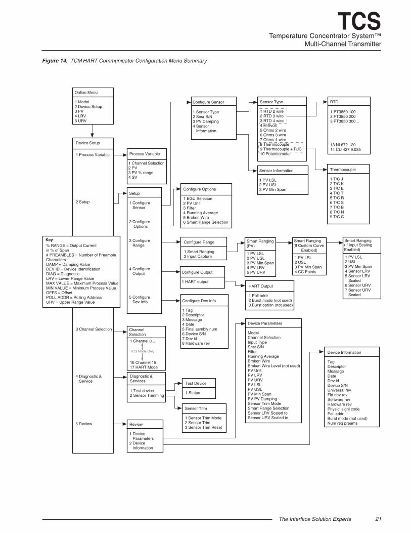
Figure 14. TCM HART Communicator Configuration Menu Summary
Online Menu
1 Model 2 Device Setup3 PV4 LRV5 URV
1 Process Variable
2 Setup
3 Channel Selection
4 Diagnostic & Service
1 Channel Selection 2 PV3 PV % range4 SV
Setup
1 Configure Sensor
2 Configure Options
3 Configure Range
4 Configure Output
5 Configure Dev Info
Configure Sensor Sensor Type
1 RTD 2 wire2 RTD 3 wire3 RTD 4 wire4 Millivolt5 Ohms 2 wire6 Ohms 3 wire7 Ohms 4 wire8 Thermocouple9 Thermocouple + RJC10 Potentiometer
RTD
Thermocouple
1 T/C J2 T/C K3 T/C E4 T/C T5 T/C R6 T/C S7 T/C B8 T/C N9 T/C C
Sensor Information
1 PV LSL2 PV USL3 PV Min SpanConfigure Options
1 EGU Selecton2 PV Unit3 Filter4 Running Average 5 Broken Wire6 Smart Range Selection
Configure Range
1 Smart Ranging 2 Input Capture
Configure Output
1 HART outputHART Output
1 Poll addr2 Burst mode (not used)3 Burst option (not used)
Configure Dev Info
1 Tag2 Descriptor3 Message4 Date5 Final asmbly num 6 Device S/N7 Dev id8 Hardware rev
Diagnostic &Services
Review
1 Device Parameters2 Device Information
Sensor Trim
1 Sensor Trim Mode2 Sensor Trim3 Sensor Trim Reset
Device Parameters
ModelChannel SelectionInput TypeSnsr S/N FilterRunning AverageBroken WireBroken Wire Level (not used)PV UnitPV LRVPV URVPV LSLPV USLPV Min SpanPV PV DampingSensor Trim ModeSmart Range Selection Sensor LRV Scaled toSensor URV Scaled to
Device Information
TagDescriptorMessageDateDev id Device S/N Universal revFld dev revSoftware revHardware revPhysicl signl codePoll addrBurst mode (not used) Num req preams
Key
Process Variable
1 Sensor Type2 Snsr S/N 3 PV Damping4 Sensor Information
1 PT3850 1002 PT3850 2003 PT3850 300...
13 NI 672 12014 CU 427 9.035
1 Test device2 Sensor Trimming
% RANGE = Output Current in % of Span # PREAMBLES = Number of PreambleCharacters DAMP = Damping Value DEV ID = Device Identification DIAG = Diagnostic LRV = Lower Range Value MAX VALUE = Maximum Process Value MIN VALUE = Minimum Process Value OFFS = Offset POLL ADDR = Polling Address URV = Upper Range Value
Device Setup
Test Device
1 Status
Channel Selection
1 Channel 0...
16 Channel 1517 HART Mode
Smart Ranging (PV)
1 PV LSL2 USL 3 PV Min Span4 Sensor LRV 5 Sensor LRV Scaled6 Sensor URV7 Sensor URV Scaled
Smart Ranging(If Input Scaling Enabled)
Smart Ranging(If Custom Curve
Enabled)
1 PV LSL2 USL 3 PV Min Span4 CC Points
1 PV LSL2 PV USL 3 PV Min Span4 PV LRV 5 PV URV
TCS Mode Only
5 Review
22 The Interface Solution Experts
TCSTemperature Concentrator System™Multi-Channel Transmitter
The HART Communicator Menu With a Device DescriptionTo program your TCM, if your communicator is equipped with the Device Description for your instrument, follow the steps below. Refer to Figure 14 for menu parameters of steps outlined below.
Online MenuThe Online menu displays the process value as well as the lower/upper range scaled values of your application (all parameters are read-only except for Device Setup). Use the Device Setup menu to configure the TCM.
Device Setup MenuThe Device Setup menu allows you to access the following sub-menus: Process Variable, Setup, Channel Selection, Diagnostic & Services and Review. Each of these sub-menus is explained below.
Note: The Mode Setting must be set before any
configuration. This will insure that the correct MODE is active. Refer to Channel Selection to on page 23
to set Mode.
Process Variable MenuThe Process Variable menu is a read-only display that indicates the selected channel, process variable, output in percent of span (% range) and the secondary variable.
Setup MenuScroll through the Setup menu to access configuration menus for the following parameters: Configure Sensor, Configure Options, Configure Range, Configure Output and Configure Dev Info.
Setup menu parameters are detailed below.
Configure SensorThis menu allows access to sensor configuration. 1 Sensor Type– Select the sensor type you will use (RTD, Ohms, T/C or Potentiometer). You will navigate through sub-menus depending upon parameters that are being set.
Configure OptionsYou may configure the following options from this menu:
1 EGU Selection– Choose the EGU you wish displayed.
2 PV EGU– View the existing EGU setting.
3 Filter– This is used to configure the input filter which helps reduce mains-induced noise. The value selected should match the frequency of the local AC supply (50Hz or 60Hz).
4 Running Average– This feature filters the input signal. The TCM provides this feature with a user-selected value between 1 and 16. Factory default is 4.
Note: A higher Running Average setting provides smoother output transitions, however, will
reduce response time. Conversely, a lower setting provides a faster response time, but
may seem more unstable.
5 Broken Wire– If enabled (by selecting On) the TCM sends random microamp pulses through input wiring to check for broken wiring or a burned out sensor.
6 Smart Range Select– Select whether you choose to view the process variable, use a custom curve table or scale the input. Custom curve can only be set using Moore Industries’ PC Configuration Software. Input scaling configuration is performed in the Configure Range menu.
2 Snsr S/N– Assign a unique serial number to your sensor.
3 PV Damping– Allows you to introduce a delay into the response of your unit in order to stop short-lived spikes from appearing as faults and generating fault messages. The allowable PV Damping range is 0sec to 30sec.
4 Sensor Information– Displays the Upper Sensor Limit (USL), Lower Sensor Limit (LSL) and minimum span of the selected sensor type.
The Interface Solution Experts 23
TCSTemperature Concentrator System™
Multi-Channel Transmitter
Configure OutputThis menu allows you to configure your instrument’s HART output. Use this portion of the menu to configure the Poll Address.
1 Poll addr– The HART polling address is represented by a number between 0 and 15 while in HART mode. When in TCS mode, addresses 1 and 2 are used.
Configure Dev InfoThis menu allows you to configure identification parameters for your TCM.
1 Tag– Place a unique label that corresponds to your instruments location or specific usage (8 characters maximum).
2 Descriptor– Place text that is used as a description of how the instrument is being used (16 characters, maximum).
3 Message– Place additional information that may be helpful in describing the instrument or its use (32 characters, maximum).
4 Date– Store a date that corresponds to specific system function, i.e. instrument configuration date, calibration due date, preventive maintenence schedule, etc.
5 Final asmbly num– You may enter a number that is used for identification purposes, and is associated with the field device (8 characters, maximum).
6 Dev id– This is a read-only value that uniquely identifies the field device when combined with the manufacturer identification and device type.
7 Hardware rev– This value corresponds to the revision of the electronics hardware of the field device.
Configure RangeWithin the Configure Range menu are the capabilities to configure Smart Ranging and capture the input.
1 Smart Ranging– Configuration steps will vary depending on whether PV, Custom Curve or Input Scaling was selected in the Configure Options menu.
PV 1 PV LSL– Displays the lower sensor limit (LSL) of the attached sensor.
2 USL– Displays the upper sensor limit (USL) of the attached sensor.
3 PV Min Span– Indicates the allowable minimum difference between the upper range value (URV) and lower range value (LRV).
4 PV LRV– Enter the value you wish displayed as your lower range value when your process variable is output at its lower end (0%).
5 PV URV– Enter the value you wish displayed as your upper range value when your process variable is output at its upper end (100%).
If Custom Curve is Enabled 1 PV LSL– Displays the lower sensor limit (LSL) of the attached sensor.
2 PV USL– Displays the upper sensor limit (USL) of the attached sensor.
3 PV Min Span– Indicates the allowable minimum difference between the upper range value (URV) and lower range value (LRV).
4 CC Points– Displays the number of Custom Curve points you have enabled (2 to 128 points).
If Scaling is Enabled 1 PV LSL– Displays the lower sensor limit (LSL) of the attached sensor.
2 PV USL– Displays the upper sensor limit (USL) of the attached sensor.
3 PV Min Span– Indicates the allowable minimum difference between the upper range value (URV) and lower range value (LRV).
4 Sensor LRV– Enter the sensor’s lower range value (LRV).
5 Sensor LRV Scaled– Select the value you wish as
your scaled LRV (for 0% value). Allowed span is from -99999 to 99998.
6 Sensor URV– Enter the sensor’s upper range value (URV).
7 Sensor URV Scaled– Select the value you wish as your scaled URV (for 100% value). Allowed span is from -99998 to 99999.
24 The Interface Solution Experts
TCSTemperature Concentrator System™Multi-Channel Transmitter
Channel SelectionAllows you to select between TCS or HART mode*. If choosing a channel to monitor (Channel 1 through Channel 16), TCS mode is enabled. HART mode is enabled by scrolling to the end of the channel menu (Channel 17). When in HART Mode each device (1 to 16) is each treated as an individual channel.
Note: *Correct Mode must be selected in order to properly
configure system.
Diagnostic & Service MenuAllows you to perform diagnostic functions and sensor trimming.
1 Test device– Directs you to a Status sub-menu. When accessed, it causes the TCM to perform a self test of its electronics. Any errors that occur are reported on the communicator.
2 Sensor Trimming– This menu allows you to view previously configured Sensor Trim Mode settings and perform the sensor trimming procedure.
Review MenuThis is a read-only menu that provides information on both Device Parameters and Device Information. Refer to the Review menu portion of Figure 13 for a description of the parameters included in this menu.
The HART Communicator Menu Without a Device DescriptionThis section contains the instructions for programming theTCM using a HART communicator without a Device Description. If your communicator has a Device Description, please see The HART Communicator Menu with a Device Description section of this manual.
Note: Without a Device Description, you may only program
the TCM in HART mode.
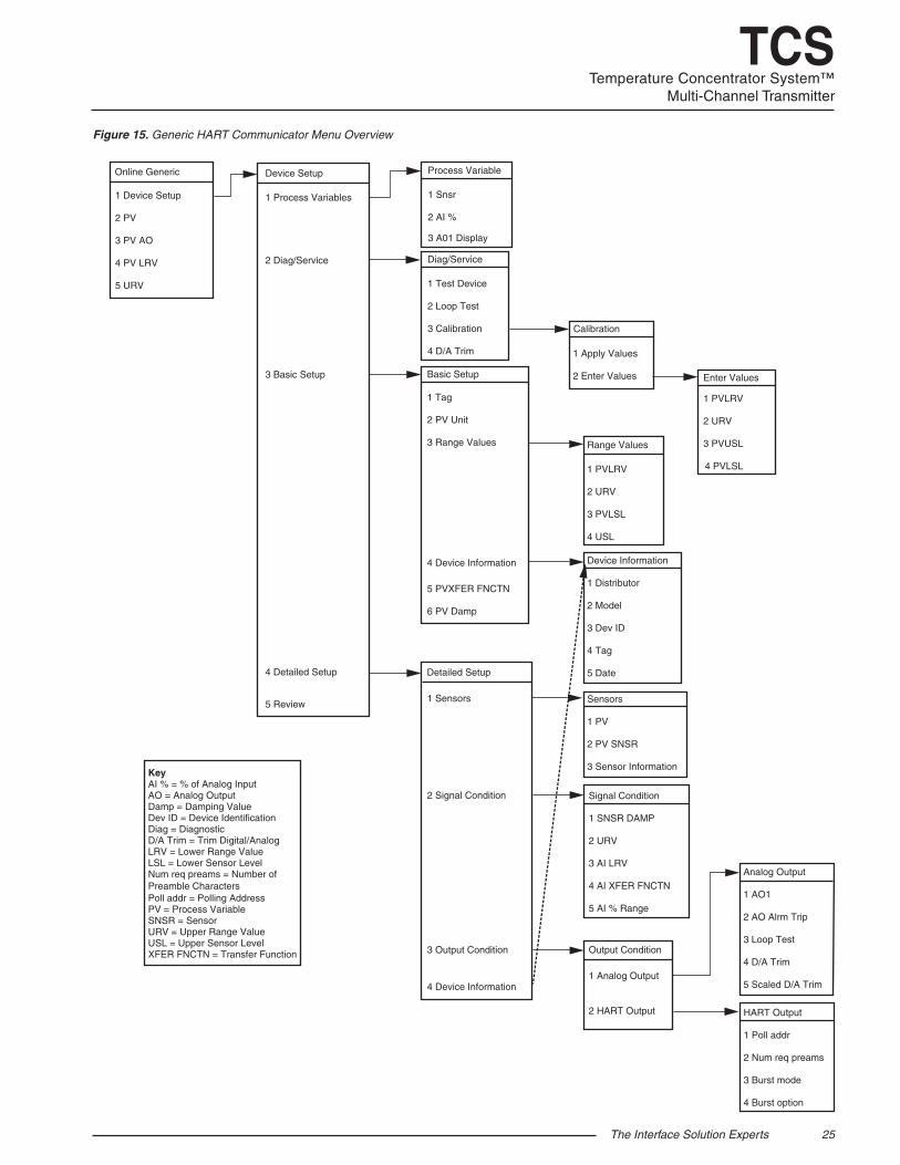
Online Generic– The initial screen, the Online Generic menu, displays the process value and the programmed upper and lower parameters of the process value. The generic HART Communicator overview menu (Figure 10) shows the menu. Use the Device Setup menu to configure your TCM.
Basic Setup– The Basic Setup menu allows you to enter a name for an individual transmitter, the units of measurement, the upper and lower range and sensor values, and a damping time between 0sec and 30sec.
HART Output– From the HART Output menu, you can enter the polling address and display the number of preamble characters sent by the master to the slave to ensure synchronization.
The Interface Solution Experts 25
TCSTemperature Concentrator System™
Multi-Channel Transmitter
Figure 15. Generic HART Communicator Menu Overview
Online Generic
1 Device Setup
2 PV
3 PV AO
4 PV LRV
5 URV
Device Setup
1 Process Variables
2 Diag/Service
3 Basic Setup
4 Detailed Setup
5 Review
Process Variable
1 Snsr
2 AI %
3 A01 Display
Diag/Service
1 Test Device
2 Loop Test
3 Calibration
4 D/A Trim
Basic Setup
1 Tag
2 PV Unit
3 Range Values
4 Device Information
5 PVXFER FNCTN
6 PV Damp
Detailed Setup
1 Sensors
2 Signal Condition
3 Output Condition
4 Device Information
Calibration
1 Apply Values
2 Enter Values
Range Values
1 PVLRV
2 URV
3 PVLSL
4 USL
Device Information
1 Distributor
2 Model
3 Dev ID
4 Tag
5 Date
Sensors
1 PV
2 PV SNSR
3 Sensor Information
Signal Condition
1 SNSR DAMP
2 URV
3 AI LRV
4 AI XFER FNCTN
5 AI % Range
Output Condition
1 Analog Output
2 HART Output
Analog Output
1 AO1
2 AO Alrm Trip
3 Loop Test
4 D/A Trim
5 Scaled D/A Trim
HART Output
1 Poll addr
2 Num req preams
3 Burst mode
4 Burst option
KeyAI % = % of Analog InputAO = Analog OutputDamp = Damping ValueDev ID = Device IdentificationDiag = DiagnosticD/A Trim = Trim Digital/AnalogLRV = Lower Range ValueLSL = Lower Sensor LevelNum req preams = Number of Preamble CharactersPoll addr = Polling AddressPV = Process VariableSNSR = SensorURV = Upper Range ValueUSL = Upper Sensor LevelXFER FNCTN = Transfer Function
Enter Values
1 PVLRV
2 URV
3 PVUSL
4 PVLSL
26 The Interface Solution Experts
TCSTemperature Concentrator System™Multi-Channel Transmitter
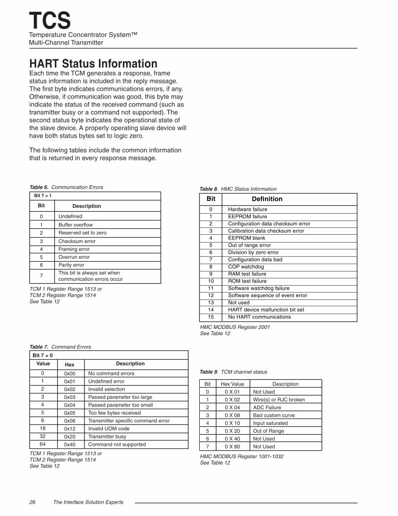
Table 9. TCM channel status
HART Status InformationEach time the TCM generates a response, frame status information is included in the reply message. The first byte indicates communications errors, if any. Otherwise, if communication was good, this byte may indicate the status of the received command (such as transmitter busy or a command not supported). The second status byte indicates the operational state of the slave device. A properly operating slave device will have both status bytes set to logic zero.
The following tables include the common information that is returned in every response message.
Table 6. Communication Errors
No command errors
Undefined error
Invalid selection
Passed parameter too large
Passed parameter too small
Too few bytes received
Transmitter specific command error
Invalid UOM code
Transmitter busy
Command not supported
Description
0x00
0x01
0x02
0x03
0x04
0x05
0x06
0x12
0x20
0x40
Bit 7 = 0
Hex
Table 7. Command Errors
0
1
2
3
4
5
6
18
32
64
Value
0 1
2 3
4
5
6 7
Undefined Buffer overflow
Reserved set to zero Checksum error
Framing error
Overrun error
Parity error
This bit is always set when communication errors occur
Description
Bit 7 = 1
Bit
Table 8. HMC Status Information
Hardware failure EEPROM failure Configuration data checksum error Calibration data checksum error EEPROM blank Out of range error Division by zero error Configuration data bad COP watchdog RAM test failure ROM test failure Software watchdog failure Software sequence of event error Not used HART device malfunction bit set No HART communications
Bit
0 1 2 3 4 5 6 7 8 9
10 11 12 13 14 15
Definition
Bit
0
1
2
3
4
5
6
7
Hex Value
0 X 01
0 X 02
0 X 04
0 X 08
0 X 10
0 X 20
0 X 40
0 X 80
Description
Not Used
Wire(s) or RJC broken
ADC Failure
Bad custom curve
Input saturated
Out of Range
Not Used
Not Used
TCM 1 Register Range 1513 orTCM 2 Register Range 1514See Table 12
HMC MODBUS Register 2001See Table 12
TCM 1 Register Range 1513 orTCM 2 Register Range 1514See Table 12
HMC MODBUS Register 1001-1032See Table 12
The Interface Solution Experts 27
TCSTemperature Concentrator System™
Multi-Channel Transmitter
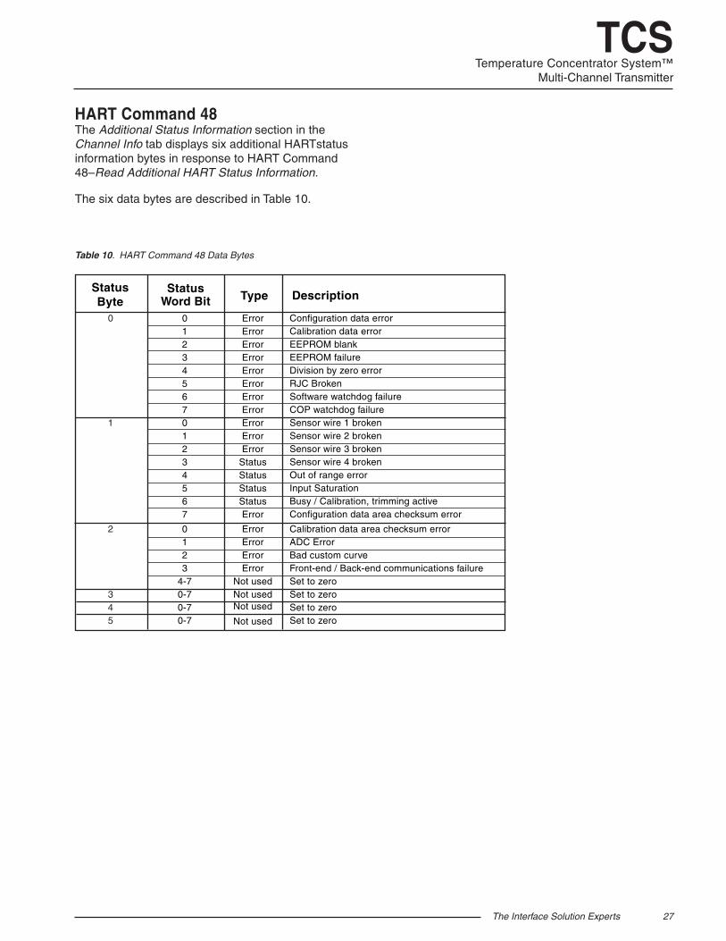
HART Command 48The Additional Status Information section in the Channel Info tab displays six additional HARTstatus information bytes in response to HART Command 48–Read Additional HART Status Information.
The six data bytes are described in Table 10.
Table 10. HART Command 48 Data Bytes
Status Word Bit Type Description
0
1
2
3 4 5
0 123456701234567 0123
4-70-70-70-7
ErrorErrorErrorErrorErrorErrorErrorErrorErrorErrorError
StatusStatusStatusStatusError ErrorErrorErrorError
Not usedNot usedNot used
Not used
Configuration data errorCalibration data errorEEPROM blankEEPROM failureDivision by zero errorRJC BrokenSoftware watchdog failureCOP watchdog failureSensor wire 1 brokenSensor wire 2 brokenSensor wire 3 brokenSensor wire 4 brokenOut of range errorInput SaturationBusy / Calibration, trimming activeConfiguration data area checksum error Calibration data area checksum errorADC ErrorBad custom curveFront-end / Back-end communications failureSet to zeroSet to zeroSet to zeroSet to zero
Status Byte
28 The Interface Solution Experts
TCSTemperature Concentrator System™Multi-Channel Transmitter
The Hart-to-MODBUS ConverterThe following section describes use and configuration of the Hart-to-MODBUS Converter (HMC).
The HMC operates in HART primary master mode communicating with either one or two TCMs, reading the TCM’s variables through its HART interface. The HMC is used to convert the TCM variables to MODBUS communication, through its dual MODBUS ports.
The HMC only talks to addresses 1 and 2. One address is assigned to one of the TCMs in the system (a maximum of two are allowed). Since the TCM outputs are seen as 16 channels from one device when in TCS mode, each address displays the status information from each channel of the TCM to which it is assigned.
MB OutputThe HMC has dual MODBUS ports for redundancy. Slave address, baud rate and character format are user-configurable (both ports use the same slave address, baud rate and character format).
Fault Alarms As an added measure, the HMC comes standard with two alarms (relays). The relay is energized when the attached device is operating properly. It is rated at 2A@250Vac (non-inductive loads, 50/60Hz). The relays can be set to send a master alarm when the HMC detects one, any, or all of the following fault conditions within the system: No HART signal; broken wire; hardware error; bad configuration; input saturated; and input out of table range.
The alarms can be set with a time delay, which specifies how long (in seconds) the alarm condition needs to exist before the alarm trips. Failsafe and Non-Failsafe alarm action is also configurable.
The HMC’s front panel has four dual color LEDs. The Fault1 and Fault2 LEDs display alarm status. Green indicates no alarm condition and red indicates an alarm condition. If only one TCM is enabled in the system, then the unused Fault LED will always be green.
Refer to the Alarms tab section for configurable alarm parameters.
TX PowerA transmitter excitation (TX) power supply (26Vdc ±3%@40mA) is standard on the HMC. This allows you to power up to two TCMs without the need for an external power supply. Refer to Figure 17 for hook-up.
Configuring the HMCAll operating parameters are set using a PC and Moore Industries’ Intelligent PC Configuration software. Configuration parameters are stored in the instrument’s memory and can be saved on your PC hard drive or external media. The transmitter communicates with the PC through an RS-232 port or optional USB cable.
Installing the Configuration SoftwareRefer to Table 11 for the equipment needed.
1. Insert the Moore Industries Interface Solution PC Configuration Software CD into the CD drive of the PC. Access the CD and open the HMC PC Configuration Software folder.
2. Double-click the installation program located in the folder. Follow the prompts to correctly install the program.
Once the Configuration Program is installed on the PC, the HMC can be connected to equipment to monitor output. You can then change the transmitter’s operating parameters.
It is not necessary to connect the HMC to a PC to create configuration files when using the PC Configuration Software. The program can be run without connecting a HMC, and most parameters can be set without input from the instrument.
This makes it easy to create a set of operating parameters, save them to external media, and download them to one or more instruments at a later time.
The HMC must be connected to the PC in order to receive (via download) a configuration file and save the configuration file from its memory.
Connecting the HMC to the PCTo connect the HMC to a PC, simply power the instrument using a 24Vdc power supply and then connect it to the PC via the RS-232 serial port using the Moore Industries Interface Cable or optional USB cable listed in Table 11.
Refer to the Recommended Ground Wiring Practices section of this manual for information regarding grounding the HMC.
The Interface Solution Experts 29
TCSTemperature Concentrator System™
Multi-Channel Transmitter
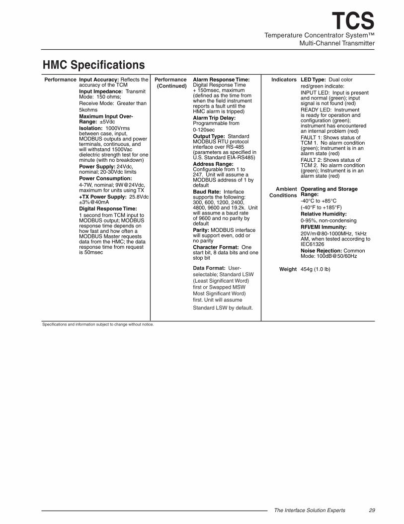
HMC SpecificationsInput Accuracy: Reflects the accuracy of the TCMInput Impedance: Transmit Mode: 150 ohms; Receive Mode: Greater than 5kohmsMaximum Input Over-Range: ±5VdcIsolation: 1000Vrms between case, input, MODBUS outputs and power terminals, continuous, and will withstand 1500Vac dielectric strength test for one minute (with no breakdown)Power Supply: 24Vdc, nominal; 20-30Vdc limitsPower Consumption: 4-7W, nominal; 9W@24Vdc, maximum for units using TX+TX Power Supply: 25.8Vdc ±3%@40mADigital Response Time: 1 second from TCM input to MODBUS output; MODBUS response time depends on how fast and how often a MODBUS Master requests data from the HMC; the data response time from request is 50msec
Performance
Weight
Performance (Continued)
Indicators
Ambient Conditions
Specifications and information subject to change without notice.
Alarm Response Time: Digital Response Time + 150msec, maximum (defined as the time from when the field instrument reports a fault until the HMC alarm is tripped)Alarm Trip Delay: Programmable from0-120secOutput Type: Standard MODBUS RTU protocol interface over RS-485 (parameters as specified in U.S. Standard EIA-RS485)Address Range: Configurable from 1 to 247. Unit will assume a MODBUS address of 1 by defaultBaud Rate: Interface supports the following: 300, 600, 1200, 2400, 4800, 9600 and 19.2k. Unit will assume a baud rate of 9600 and no parity by defaultParity: MODBUS interface will support even, odd or no parity Character Format: One start bit, 8 data bits and one stop bit
Data Format: User- selectable; Standard LSW (Least Significant Word) first or Swapped MSW Most Significant Word) first. Unit will assume
Standard LSW by default.
LED Type: Dual color red/green indicate:INPUT LED: Input is present and normal (green); input signal is not found (red)READY LED: Instrument is ready for operation and configuration (green); instrument has encountered an internal problem (red)FAULT 1: Shows status of TCM 1. No alarm condition (green); Instrument is in an alarm state (red)FAULT 2: Shows status of TCM 2. No alarm condition (green); Instrument is in an alarm state (red)
Operating and Storage Range: -40°C to +85°C (-40°F to +185°F)Relative Humidity: 0-95%, non-condensingRFI/EMI Immunity: 20V/m@80-1000MHz, 1kHz AM, when tested according to IEC61326Noise Rejection: Common Mode: 100dB@50/60Hz
454g (1.0 lb)
30 The Interface Solution Experts
TCSTemperature Concentrator System™Multi-Channel Transmitter
INPUT
READY
FAULT 1
FAULT 2
HARTMODBUSCONVERTER
COM
50mm(1.96 in)
100mm(3.94 in)
WHEN INSTALLED
WHEN INSTALLED138mm(5.43 in)
133mm(5.24 in)
126mm(4.97 in)
100mm(3.94 in)
CL
52mm(2.05 in)
48mm(1.89 in)
INPUT
READY
FAULT 1
FAULT 2
HARTMODBUSCONVERTER
COM
INPUT
TX
+IN
-IN A B S A B S
MODBUS2
MODBUS1
POWER
NC
2C
M2
NO
2
DC
(+
)
NO
1C
M1
NC
1
RELAY1
RELAY2 D
CC
(-)
GN
D
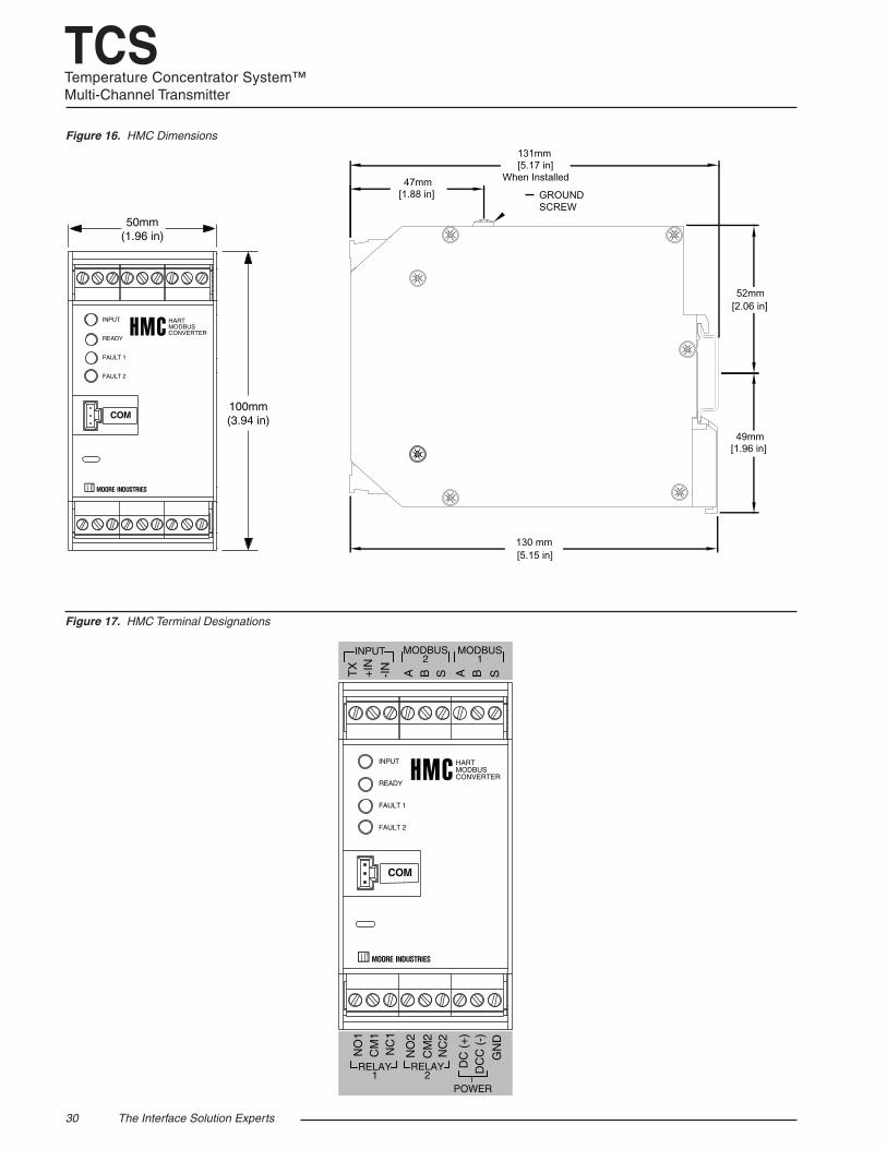
Figure 17. HMC Terminal Designations
Figure 16. HMC Dimensions
130 mm [5.15 in]
49mm [1.96 in]
52mm [2.06 in]
131mm [5.17 in]
When Installed47mm [1.88 in] GROUND
SCREW
Lorem ipsum
The Interface Solution Experts 31
TCSTemperature Concentrator System™
Multi-Channel Transmitter
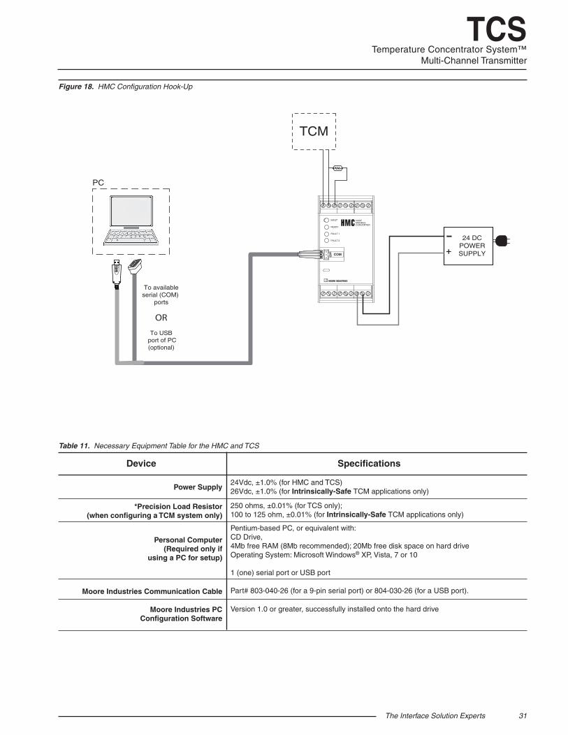
Figure 18. HMC Configuration Hook-Up
INPUT
READY
FAULT 1
FAULT 2
HARTMODBUSCONVERTER
COM
PC
To availableserial (COM)
ports
To USB port of PC(optional)
OR
24 DCPOWERSUPPLY
TCM
+-
Table 11. Necessary Equipment Table for the HMC and TCS
Power Supply
*Precision Load Resistor (when configuring a TCM system only)
Personal Computer
(Required only if using a PC for setup)
Moore Industries Communication Cable
Moore Industries PC Configuration Software
24Vdc, ±1.0% (for HMC and TCS) 26Vdc, ±1.0% (for Intrinsically-Safe TCM applications only) 250 ohms, ±0.01% (for TCS only); 100 to 125 ohm, ±0.01% (for Intrinsically-Safe TCM applications only) Pentium-based PC, or equivalent with: CD Drive, 4Mb free RAM (8Mb recommended); 20Mb free disk space on hard drive Operating System: Microsoft Windows® XP, Vista, 7 or 10 1 (one) serial port or USB port Part# 803-040-26 (for a 9-pin serial port) or 804-030-26 (for a USB port). Version 1.0 or greater, successfully installed onto the hard drive
Device Specifications
32 The Interface Solution Experts
TCSTemperature Concentrator System™Multi-Channel Transmitter
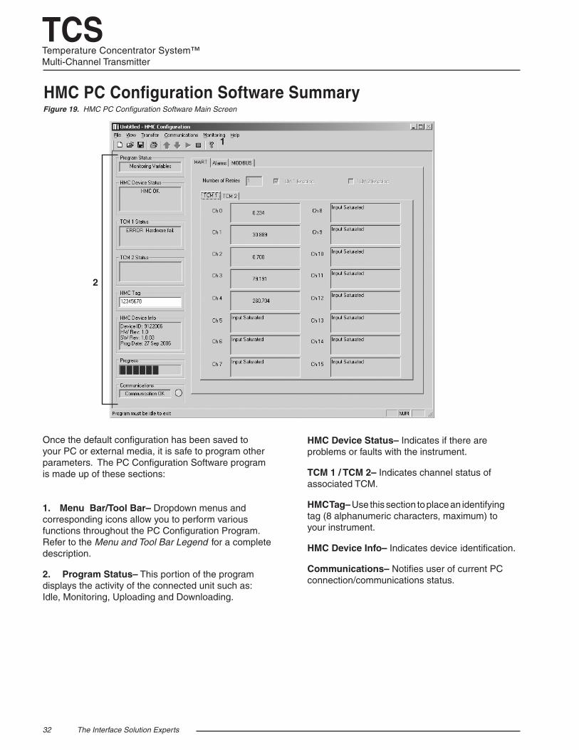
Figure 19. HMC PC Configuration Software Main Screen
HMC PC Configuration Software Summary
HMC Device Status– Indicates if there are problems or faults with the instrument.
TCM 1 / TCM 2– Indicates channel status of associated TCM.
HMC Tag– Use this section to place an identifying tag (8 alphanumeric characters, maximum) to your instrument.
HMC Device Info– Indicates device identification.
Communications– Notifies user of current PC connection/communications status.
Once the default configuration has been saved to your PC or external media, it is safe to program other parameters. The PC Configuration Software program is made up of these sections: 1. Menu Bar/Tool Bar– Dropdown menus and corresponding icons allow you to perform various functions throughout the PC Configuration Program. Refer to the Menu and Tool Bar Legend for a complete description.
2. Program Status– This portion of the program displays the activity of the connected unit such as: Idle, Monitoring, Uploading and Downloading.
1
2
The Interface Solution Experts 33
TCSTemperature Concentrator System™
Multi-Channel Transmitter
Configuration ScreensNote:
Unless otherwise noted, ensure that the PC Configuration Program is idle before making any
selections or configuration changes to the program. Also, when attempting to download or upload,
monitoring must be stopped. To do this, click Stop in the Monitoring dropdown menu, or click the Stop
Monitoring icon on the Tool Bar.
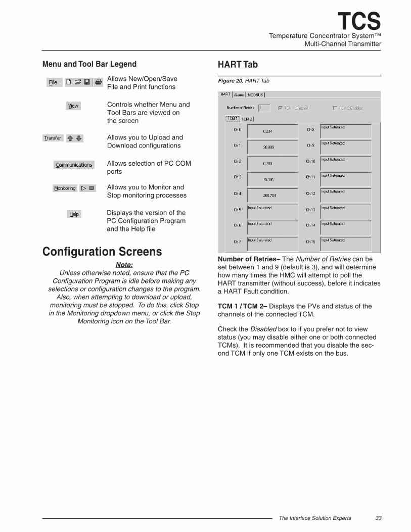
Figure 20. HART Tab
Menu and Tool Bar Legend
Allows you to Upload and Download configurations
Allows selection of PC COM ports
Allows you to Monitor and Stop monitoring processes
Controls whether Menu and Tool Bars are viewed on the screen
Displays the version of the PC Configuration Programand the Help file
Allows New/Open/Save File and Print functions
HART Tab
Number of Retries– The Number of Retries can be set between 1 and 9 (default is 3), and will determine how many times the HMC will attempt to poll the HART transmitter (without success), before it indicates a HART Fault condition.
TCM 1 / TCM 2– Displays the PVs and status of the channels of the connected TCM.
Check the Disabled box to if you prefer not to view status (you may disable either one or both connected TCMs). It is recommended that you disable the sec-ond TCM if only one TCM exists on the bus.
34 The Interface Solution Experts
TCSTemperature Concentrator System™Multi-Channel Transmitter
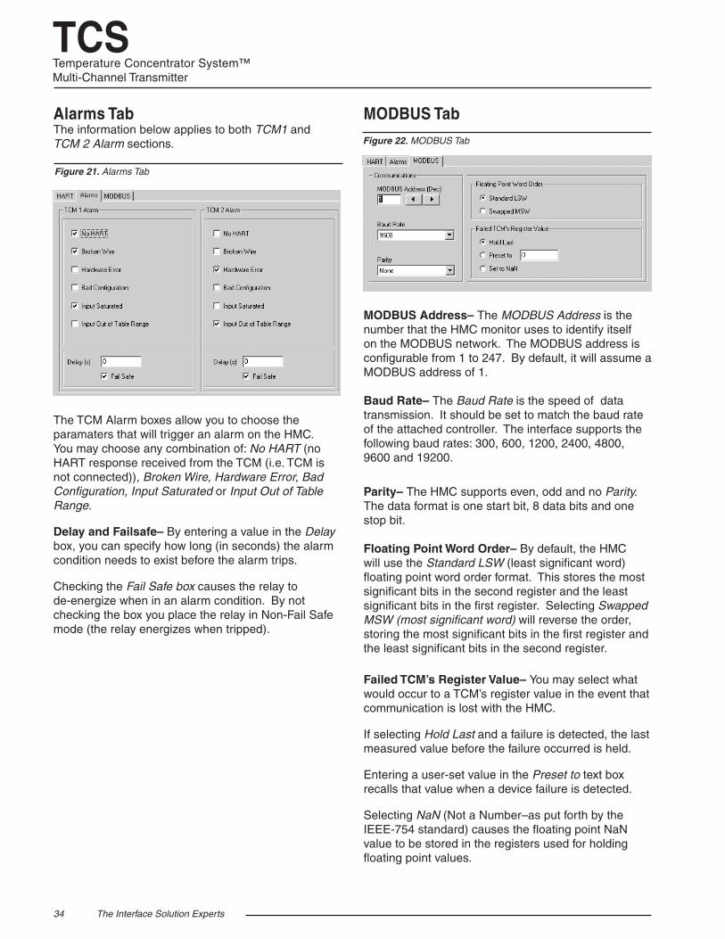
MODBUS Tab
MODBUS Address– The MODBUS Address is the number that the HMC monitor uses to identify itself on the MODBUS network. The MODBUS address is configurable from 1 to 247. By default, it will assume a MODBUS address of 1.
Baud Rate– The Baud Rate is the speed of data transmission. It should be set to match the baud rate of the attached controller. The interface supports the following baud rates: 300, 600, 1200, 2400, 4800, 9600 and 19200.
Parity– The HMC supports even, odd and no Parity. The data format is one start bit, 8 data bits and one stop bit. Floating Point Word Order– By default, the HMC will use the Standard LSW (least significant word) floating point word order format. This stores the most significant bits in the second register and the least significant bits in the first register. Selecting Swapped MSW (most significant word) will reverse the order, storing the most significant bits in the first register and the least significant bits in the second register.
Failed TCM’s Register Value– You may select what would occur to a TCM’s register value in the event that communication is lost with the HMC.
If selecting Hold Last and a failure is detected, the last measured value before the failure occurred is held.
Entering a user-set value in the Preset to text box recalls that value when a device failure is detected.
Selecting NaN (Not a Number–as put forth by the IEEE-754 standard) causes the floating point NaN value to be stored in the registers used for holding floating point values.
Figure 22. MODBUS Tab
Alarms TabThe information below applies to both TCM1 and TCM 2 Alarm sections.
The TCM Alarm boxes allow you to choose the paramaters that will trigger an alarm on the HMC. You may choose any combination of: No HART (no HART response received from the TCM (i.e. TCM is not connected)), Broken Wire, Hardware Error, Bad Configuration, Input Saturated or Input Out of Table Range.
Delay and Failsafe– By entering a value in the Delay box, you can specify how long (in seconds) the alarm condition needs to exist before the alarm trips.
Checking the Fail Safe box causes the relay to de-energize when in an alarm condition. By not checking the box you place the relay in Non-Fail Safe mode (the relay energizes when tripped).
Figure 21. Alarms Tab
The Interface Solution Experts 35
TCSTemperature Concentrator System™
Multi-Channel Transmitter
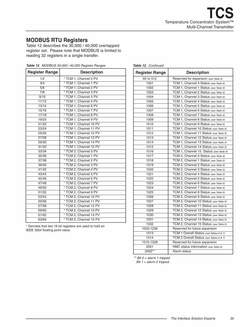
MODBUS RTU RegistersTable 12 describes the 30,000 / 40,000 overlapped register set. Please note that MODBUS is limited to reading 32 registers in a single transfer.
Table 12. MODBUS 30,000 / 40,000 Register Ranges Table 12. Continued
Register Range Description
* TCM 1, Channel 0 PV* TCM 1, Channel 1 PV* TCM 1, Channel 2 PV* TCM 1, Channel 3 PV* TCM 1, Channel 4 PV* TCM 1, Channel 5 PV* TCM 1, Channel 6 PV* TCM 1, Channel 7 PV* TCM 1, Channel 8 PV* TCM 1, Channel 9 PV* TCM 1, Channel 10 PV* TCM 1, Channel 11 PV* TCM 1, Channel 12 PV* TCM 1, Channel 13 PV* TCM 1, Channel 14 PV* TCM 1, Channel 15 PV* TCM 2, Channel 0 PV* TCM 2, Channel 1 PV* TCM 2, Channel 2 PV* TCM 2, Channel 3 PV* TCM 2, Channel 4 PV* TCM 2, Channel 5 PV* TCM 2, Channel 6 PV* TCM 2, Channel 7 PV* TCM 2, Channel 8 PV* TCM 2, Channel 9 PV* TCM 2, Channel 10 PV* TCM 2, Channel 11 PV* TCM 2, Channel 12 PV* TCM 2, Channel 13 PV* TCM 2, Channel 14 PV* TCM 2, Channel 15 PV
1/23/45/67/89/1011/1213/1415/1617/1819/2021/2223/2425/2627/2829/3031/3233/3435/3637/3839/4041/4243/4445/4647/4849/5051/5253/5455/5657/5859/6061/6263/64
65 to 51210011002100310041005100610071008100910101011101210131014101510161017101810191020102110221023102410251026102710281029103010311032
1033-125615131514
1515-15282001
2002**
Reserved for expansion (see Table 9)
TCM 1, Channel 0 Status (see Table 9)
TCM 1, Channel 1 Status (see Table 9)
TCM 1, Channel 2 Status (see Table 9)
TCM 1, Channel 3 Status (see Table 9)
TCM 1, Channel 4 Status (see Table 9)
TCM 1, Channel 5 Status (see Table 9)
TCM 1, Channel 6 Status (see Table 9)
TCM 1, Channel 7 Status (see Table 9)
TCM 1, Channel 8 Status (see Table 9)
TCM 1, Channel 9 Status (see Table 9)
TCM 1, Channel 10 Status (see Table 9)
TCM 1, Channel 11 Status (see Table 9)
TCM 1, Channel 12 Status (see Table 9)
TCM 1, Channel 13 Status (see Table 9)
TCM 1, Channel 14 Status (see Table 9)
TCM 1, Channel 15 Status (see Table 9)
TCM 2, Channel 0 Status (see Table 9)
TCM 2, Channel 1 Status (see Table 9)
TCM 2, Channel 2 Status (see Table 9)
TCM 2, Channel 3 Status (see Table 9)
TCM 2, Channel 4 Status (see Table 9)
TCM 2, Channel 5 Status (see Table 9)
TCM 2, Channel 6 Status (see Table 9)
TCM 2, Channel 7 Status (see Table 9)
TCM 2, Channel 8 Status (see Table 9)
TCM 2, Channel 9 Status (see Table 9)
TCM 2, Channel 10 Status (see Table 9)
TCM 2, Channel 11 Status (see Table 9)
TCM 2, Channel 12 Status (see Table 9)
TCM 2, Channel 13 Status (see Table 9)
TCM 2, Channel 14 Status (see Table 9)
TCM 2, Channel 15 Status (see Table 9)
Reserved for future expansionTCM 1 Overall Status (see Tables 6 & 7)
TCM 2 Overall Status (see Tables 6 & 7)
Reserved for future expansionHMC status information (see Table 8)
Alarm status
DescriptionRegister Range
* Denotes that two 16 bit registers are used to hold an IEEE 32bit floating point value.
** Bit 0 = alarm 1 tripped Bit 1 = alarm 2 tripped
36 The Interface Solution Experts
TCSTemperature Concentrator System™Multi-Channel Transmitter
InstallationInstallation consists of physically mounting the unit and completing the electrical connections.
Mounting the TCM and HMC
The TCM and HMC can be mounted on 35mm Top Hat EN50022 DIN mounting rails.
Making the Electrical Connections
To install the TCM, refer to Figure 8.
To install the TCS system, refer to Figures 3 and 5. For installation in an intrinsically-safe application refer to Figure 23.
For HART applications, ensure that the loop resistance is between 250 and 1100 ohms. For Intrinsically-Safe applications, use no more than 125-150 ohms due to the internal resistance of I.S barrier.
When installing any Moore Industries product, always follow all local regulations and standards for grounding, shielding, and safety.
WARNING: Terminals on this unit may be connected to hazardous voltages. Before making ANY connections to this unit,
always remove power from the loop or instrument power terminals.
Contact/Load Suppression
When the instrument relays are used to switch an inductive load such as an external relay coil, contactor, solenoid, large voltage spikes may be created in nearby cable harnesses. When excessive, these voltage spikes can disrupt the operation of all nearby electronics including this product. Inductive loads should have suppression devices installed at the load (for external relays this would be right across the relay coil itself). Usually this is a simple diode for dc circuits. AC circuits routinely use an R-C snubber. Please follow the external load manufacturer instructions for their recommended suppression kits.
Recommended Ground Wiring Practices
Moore Industries recommends the following ground wiring practices:
• Any Moore Industries product in a metal case or housing should be grounded.
• The protective earth conductor must be connected to a system safety earth ground before making other connections.
• All input signals to, and output signals from, Moore Industries’ products should be wired using a shielded, twisted pair wiring technique. Shields should be connected to an earth or safety ground.
• For the best shielding, the shield should be run all the way from the signal source to the receiving device. (see Note)
• The maximum length of unshielded input and output signal wiring should be 2 inches.
Note: Some of Moore Industries’ instruments can be
classified as receivers (IPT, IPX, etc.) and some can be classified as transmitters (TRX, TRY, etc.) while some are both a receiver and a transmitter (SPA, HIM, etc). Hence, your shield ground connections
should be appropriate for the type of signal line being shielded. The shield should be grounded at
the signal source and not at the receiver.
Supply Wiring All power connections should be made with the proper wire.
The end of each conductor should be stripped no more than 8mm (0.31 in). The end of the stripped wire should be tinned with solder, or inserted into a ferrule and crimped before being placed into a terminal block.
Conductors connected to screw-type connections should have a ring-lug or spade-lug crimped onto the wire end. Tighten the screws on the terminal block to 4.4 - 5.3 lbf•in (0.5 - 0.6 N•m).
CE ConformityInstallation of any Moore Industries’ products that carry the CE marking must adhere to the guidelines in the Recommended Ground Wiring Practices section in order to meet the EN 61326 requirements set forth in the applicable EMC directive.
The Interface Solution Experts 37
TCSTemperature Concentrator System™
Multi-Channel Transmitter
OperationOnce programmed, calibrated, installed and supplied with the correct power, the TCM and HMC begin to operate immediately. Depending upon environmental conditions, they can be expected to operate unattended for extended periods of time.
HART ProtocolThis section of the manual gives an overview of the HART format used by TCM module during operation. Use the information in this section to process the data provided by the module(s) during operation. For more information on the HART protocol, contact the HART Foundation at:
HART Communication Foundation 9390 Research Blvd., Suite I-350 Austin, TX 78759-6540 USA Phone: (512) 794-0369 Fax: (512) 794-3904 www.hartcomm.org
MaintenanceMoore Industries suggests a quick check for terminal tightness and general unit condition every 6-8 months. Always adhere to any site requirements for programmed maintenance.
Customer SupportIf service assistance is ever required for an device in your application, refer to the back cover of this manual for the telephone numbers to Moore Industries’ customer service department. If possible, make a note of the model number of the unit before calling. For fastest assistance, have the following information available: serial number, the job number and purchase order number under which it was shipped
38 The Interface Solution Experts
TCSTemperature Concentrator System™Multi-Channel Transmitter
Installation in Hazardous LocationsThis section contains important information regarding installation of the TCM in Hazardous Area Locations.
WARNING: Do not separate power connector when energized.
WARNING: Substitution of components is not allowed, as it may impair the intrinsic safety.
AVERTISSEMENT: La substitution de composants peut compromettre la sécurité intrinséque.
WARNING: To prevent ignition of flammable or combustible atmospheres, disconnect power before servicing.
AVERTISSEMENT: Risque d’explosion. Avant de déconnecter l’equipement, couper le courant ou s’assurer que débrancher tant que l’emplacement est désigné non dangereux.
WARNING: Explosion Hazard. Do not disconnect equipment when a flammable or combustible atmosphere is present.
AVERTISSEMENT: Risque d’explosion. Ne pas débrancher tant que le circuit est sous tension, a moins qu’il ne s’ agisse d’un emplacement non dangereux. The Figure 23 (next page) must be used for units that are to operate in areas requiring intrinsically-safe instrumentation. Refer to the Specific Conditions outlined below before proceeding with installation.
Specific Conditions of UseThe following instructions must be adhered to when the TCM is used in hazardous ‘Classified’ locations and potentially explosive atmospheres. cFMus Installations
I. Intrinsically Safe Applications Ex ia Zones 0 & 1, Class I, Division 1, Groups A-D
1. The Model TCM Temperature Concentrator Module shall be installed in an enclosure which maintains an ingress protection rating of IP20.
2. The Model TCM Temperature Concentrator Module shall be installed in final enclosure which meets the requirements of ANSI/ISA 61010-1 and the National Electrical Code©.
3. For Zone 0 and Division 1 installations, the final enclosure shall not contain more than 10% in total of aluminum, magnesium, titanium and zirconium, or 7.5% in total of magnesium, titanium and zirconium. For Zone 1 installations, the final enclosure shall not contain 7.5% in total magnesium.
4. If the final enclosure is non-metallic, under certain extreme circumstances, the non-metallic parts incorporated in the final enclosure of this equipment may generate an ignition-capable level of electrostatic charge. Therefore particularly when it is used for applications that specifically require group II, Zone 0 and Division 1 located equipment, that the equipment shall not be installed in a location where the external conditions are conducive to the build-up of electrostatic charge on such surfaces. Additionally, the equipment shall only be cleaned with a damp cloth.
5. The COM port shall not be used in the hazardous area. 6. The Model TCM Temperature Concentrator Module shall be installed in a final enclosure which meets the requirements of C22.2. No. 1010-1 and the Canadian Electrical Code.
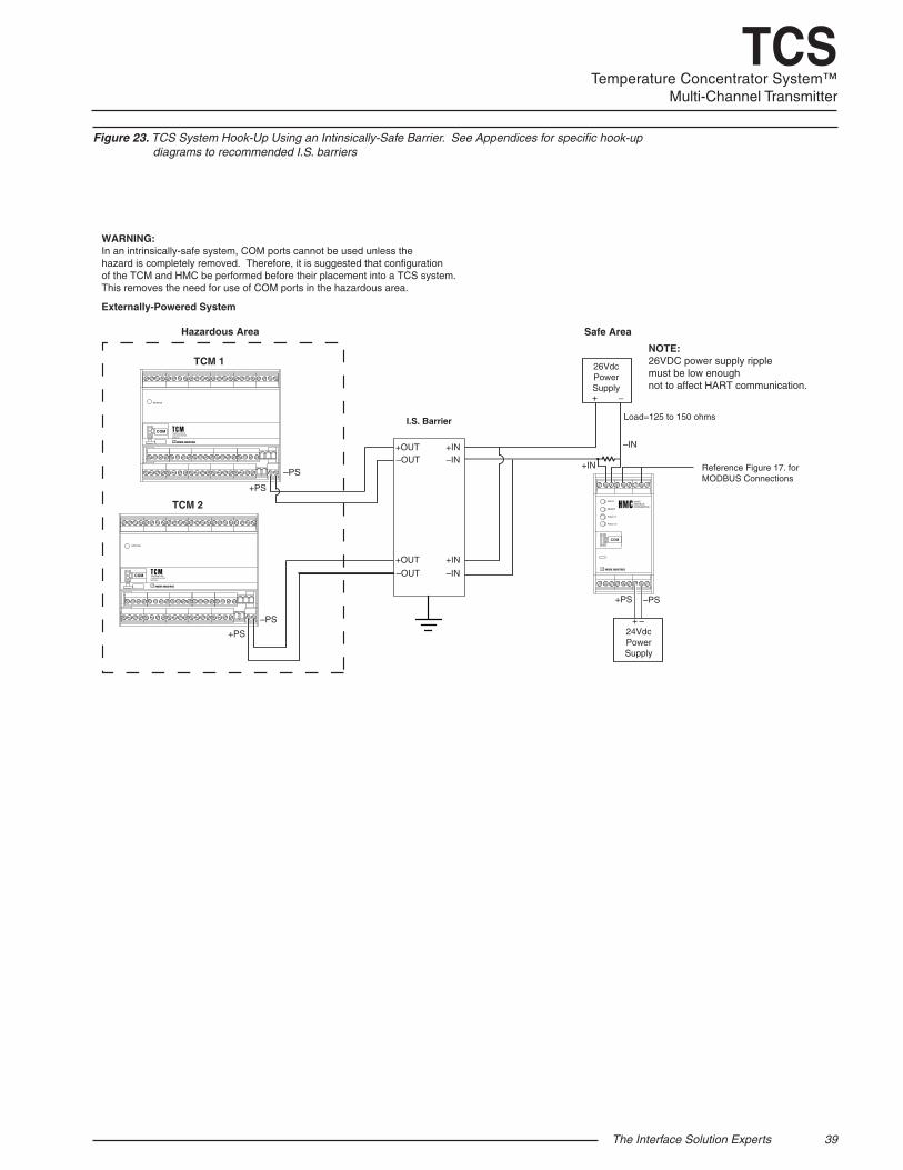
The Interface Solution Experts 39
TCSTemperature Concentrator System™
Multi-Channel Transmitter
WARNING:In an intrinsically-safe system, COM ports cannot be used unless the hazard is completely removed. Therefore, it is suggested that configurationof the TCM and HMC be performed before their placement into a TCS system.This removes the need for use of COM ports in the hazardous area.
NOTE:26VDC power supply ripple must be low enoughnot to affect HART communication.
Externally-Powered System
TCM 1
TCM 2
+PS
–PS
+PS
–PS + –
24VdcPowerSupply
+PS –PS
Load=125 to 150 ohms
Reference Figure 17. forMODBUS Connections
+IN
INPUT
READY
FAULT 1
FAULT 2
HARTMODBUSCONVERTER
COM
STATUS
TEMPERATURECONCENTRATORMODULE
COM
STATUS
TEMPERATURECONCENTRATORMODULE
COM
–IN
+ –
26VdcPowerSupply
I.S. Barrier
+IN–IN
+IN
–IN
+OUT
+OUT
–OUT
–OUT
Safe AreaHazardous Area
Figure 23. TCS System Hook-Up Using an Intinsically-Safe Barrier. See Appendices for specific hook-up diagrams to recommended I.S. barriers
40 The Interface Solution Experts
TCSTemperature Concentrator System™Multi-Channel Transmitter
II. Non-Incendive Applications, Zone 2, Class I & II, Division 2, Class III, Division 1 & 2, Groups A-D 1. The Model TCM Temperature Concentrator Module shall be installed in a final enclosure which meets the requirements of ANSI/ISA 61010-1 and the National Electrical Code© or meets the requirements of C22.2 No. 1010-1 and the Canadian Electrical Code.
2. The COM port shall not be used in the hazardous area.
European Union Installations (ATEX 2014/30/EU Directive) I. Intrinsically Safe Applications II 1 G Ex ia llC, Zones 0, 1 or 2
1. The Model TCM Temperature Concentrator Module shall be installed in an enclosure which maintains an ingress protection rating of IP20.
2. For Zone 0, the final enclosure shall not contain more than 10% in total of aluminum,magnesium, titanium and zirconium; or 7.5% in total of magnesium, titanium and zirconium. For Zone 1 installations, the final enclosure shall not contain 7.5% in total of magnesium.
3. If the final enclosure is non-metallic, under certain extreme circumstances, the non-metallic parts incorporated in the final enclosure of this equipment may generate an ignition-capable level of electrostatic charge. Therefore particularly when it is used for applications that specifically require Group II, Zone 0 located equipment, that the equipment shall not be installed in a location where the external conditions are conducive to the build-up of electrostatic charge on such surfaces. Additionally, the equipment shall only be cleaned with a damp cloth.
4. Using the box provided on the nameplate, the User shall permanently mark the protection type chosen for the specific installation. Once the type of protection has been markedit shall not be changed.
5. The COM port shall not be used in the hazardous area.
II. Type “n” Applications ll 3 G Ex nA IIC, Zone 2
1. If the Model TCM Temperature Concentrator Module is installed as Category 3 equipment, it shall be installed in an enclosure which maintains an ingress protection rating of IP54 and meets the enclosure requirements of EN60079-0 and EN60079-15.
2. If the final enclosure is non-metallic, under certain extreme circumstances, the non-metallic parts incorporated in the final enclosure of this equipment may generate an ignition-capable level of electrostatic charge. Therefore particularly when it is used for applications that specifically require Group II, Zone 0 located equipment, that the equipment shall not be installed in a location where the external conditions are conducive to the build-up of electrostatic charge on such surfaces. Additionally, the equipment shall only be cleaned with a damp cloth.
3. The Model TCM Temperature Concentrator Module shall contain external transient protection to prevent the supply voltage from exceeding 46.2V including tolerance. 4. Using the box provided on the nameplate, the User shall permanently mark the protection type chosen for the specific installation. Once the type of protection has been marked it shall not be changed.
5. The COM port shall not be used in the hazardous area.
The Interface Solution Experts 41
TCSTemperature Concentrator System™
Multi-Channel Transmitter
IECEx Installations
I. Intrinsically Safe Applications Ex ia IIC, Zones 0, 1 or 2
1. The Model TCM Temperature Concentrator Module shall be installed in an enclosure which maintains an ingress protection rating of IP20.
2. For Zone 0, the final enclosure shall not contain more than 10% in total of aluminum,magnesium, titanium and zirconium; or 7.5% in total of magnesium, titanium and zirconium. For Zone 1 installations, the final enclosure shall not contain 7.5% in total of magnesium.
3. If the final enclosure is non-metallic, under certain extreme circumstances, the non-metallic parts incorporated in the final enclosure of this equipment may generate an ignition-capable level of electrostatic charge. Therefore particularly when it is used for applications that specifically require Group II, Zone 0 located equipment, that the equipment shall not be installed in a location where the external conditions are conducive to the build-up of electrostatic charge on such surfaces. Additionally, the equipment shall only be cleaned with a damp cloth.
4. Using the box provided on the nameplate, the User shall permanently mark the protection type chosen for the specific installation. Once the type of protection has been markedit shall not be changed.
5. The COM port shall not be used in the hazardous area.
Type “n” Applications Ex nA [nL] IIC, Zone 2
1. If the Model TCM Temperature Concentrator Module is installed as Category 3 equipment, it shall be installed in an enclosure which maintains an ingress protection rating of IP54 and meets the enclosure requirements of EN60079-0 and EN60079-15.
2. If the final enclosure is non-metallic, under certain extreme circumstances, the non-metallic parts incorporated in the final enclosure of this equipment may generate an ignition-capable level of electrostatic charge. Therefore particularly when it is used for applications that specifically require Group II, Zone 0 located equipment, that the equipment shall not be installed in a location where the external conditions are conducive to the build-up of electrostatic charge on such surfaces. Additionally, the equipment shall only be cleaned with a damp cloth.
3. The Model TCM Temperature Concentrator Module shall contain external transient protection to prevent the supply voltage from exceeding 46.2V including tolerance. 4. Using the box provided on the nameplate, the User shall permanently mark the protection type chosen for the specific installation. Once the type of protection has been marked it shall not be changed.
5. The COM port shall not be used in the hazardous area.
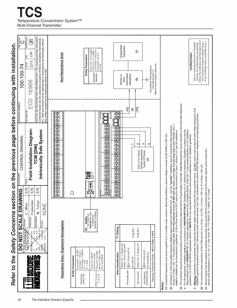
42 The Interface Solution Experts
TCSTemperature Concentrator System™Multi-Channel Transmitter
Ref
er t
o t
he
Saf
ety
Co
nce
rns
sect
ion
on
th
e p
revi
ou
s p
age
bef
ore
co
nti
nu
ing
wit
h in
stal
lati
on
.
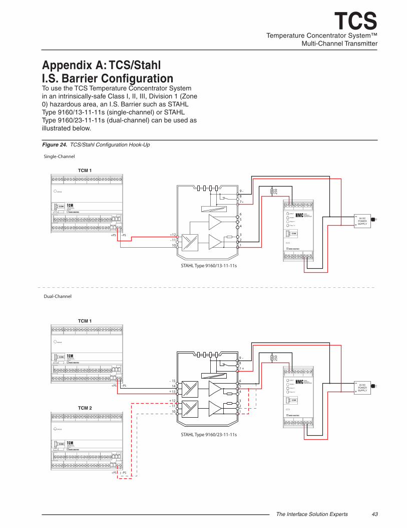
The Interface Solution Experts 43
TCSTemperature Concentrator System™
Multi-Channel Transmitter
Figure 24. TCS/Stahl Configuration Hook-Up
Appendix A: TCS/Stahl I.S. Barrier ConfigurationTo use the TCS Temperature Concentrator System in an intrinsically-safe Class I, II, III, Division 1 (Zone 0) hazardous area, an I.S. Barrier such as STAHL Type 9160/13-11-11s (single-channel) or STAHL Type 9160/23-11-11s (dual-channel) can be used as illustrated below.
123
101112
4
56
7
89
TCM 1
STATUS
TEMPERATURECONCENTRATORMODULE
COM
TCM 2
STATUS
TEMPERATURECONCENTRATORMODULE
COM
INPUT
READY
FAULT 1
FAULT 2
HARTMODBUSCONVERTER
COM
+PS –PS
+PS –PS
1
23
10
11-
-
12+
+
-
+
13
1415
4
56
7
89 25
0
24 DCPOWERSUPPLY+
-
TCM 1
STATUS
TEMPERATURECONCENTRATORMODULE
COM
INPUT
READY
FAULT 1
FAULT 2
HARTMODBUSCONVERTER
COM+PS –PS
-+
-
+
24 DCPOWERSUPPLY+
-
250
STAHL Type 9160/13-11-11s
Dual-Channel
Single-Channel
STAHL Type 9160/23-11-11s
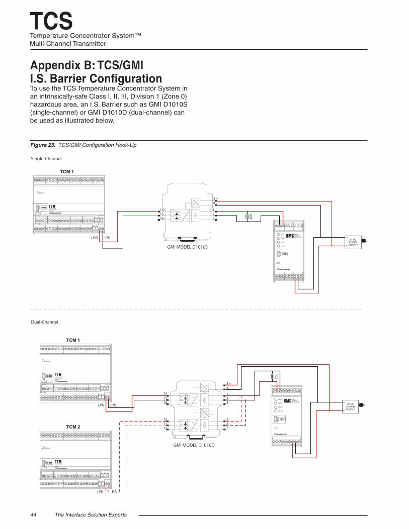
44 The Interface Solution Experts
TCSTemperature Concentrator System™Multi-Channel Transmitter
Figure 25. TCS/GMI Configuration Hook-Up
Appendix B: TCS/GMI I.S. Barrier ConfigurationTo use the TCS Temperature Concentrator System in an intrinsically-safe Class I, II, III, Division 1 (Zone 0) hazardous area, an I.S. Barrier such as GMI D1010S (single-channel) or GMI D1010D (dual-channel) can be used as illustrated below.
TCM 1
STATUS
TEMPERATURECONCENTRATORMODULE
COM
TCM 2
STATUS
TEMPERATURECONCENTRATORMODULE
COM
INPUT
READY
FAULT 1
FAULT 2
HARTMODBUSCONVERTER
COM
+PS –PS
+PS –PS
24 DCPOWERSUPPLY+
-
INPUT
READY
FAULT 1
FAULT 2
HARTMODBUSCONVERTER
COM
+PS –PS24 DC
POWERSUPPLY+
-
GMI MODEL D1010D
==
=
=
=141516
3 +4 -
128
==
=
=
=101112
567
GMI MODEL D1010S
==
=
=
=141516
3 +4 -
128
TCM 1
STATUS
TEMPERATURECONCENTRATORMODULE
COM
250
250
Dual-Channel
Single-Channel
To return equipment to Moore Industries for repair, follow these four steps: 1. Call Moore Industries and request a Returned Material Authorization (RMA) number. Warranty Repair – If you are unsure if your unit is still under warranty, we can use the unit’s serial number to verify the warranty status for you over the phone. Be sure to include the RMA number on all documentation. Non-Warranty Repair – If your unit is out of warranty, be prepared to give us a Purchase Order number when you call. In most cases, we will be able to quote you the repair costs at that time. The repair price you are quoted will be a “Not To Exceed” price, which means that the actual repair costs may be less than the quote. Be sure to include the RMA number on all documentation.
2. Provide us with the following documentation:
a) A note listing the symptoms that indicate the unit needs repair
b) Complete shipping information for return of the equipment after repair
c) The name and phone number of the person to contact if questions arise at the factory
3. Use sufficient packing material and carefully pack the equipment in a sturdy shipping con-tainer.
4. Ship the equipment to the Moore Industries location nearest you. The returned equipment will be inspected and tested at the factory. A Moore Industries rep-resentative will contact the person designated on your documentation if more information is needed. The repaired equipment, or its replacement, will be returned to you in accordance with the shipping instructions furnished in your documentation.
WARRANTY DISCLAIMERTHE COMPANY MAKES NO EXPRESS, IMPLIED OR STATUTORY WAR-RANTIES (INCLUDING ANY WARRANTY OF MERCHANTABILITY OR OF FITNESS FOR A PARTICULAR PURPOSE) WITH RESPECT TO ANY GOODS OR SERVICES SOLD BY THE COMPANY. THE COMPANY DIS-CLAIMS ALL WARRANTIES ARISING FROM ANY COURSE OF DEALING OR TRADE USAGE, AND ANY BUYER OF GOODS OR SERVICES FROM THE COMPANY ACKNOWLEDGES THAT THERE ARE NO WARRANTIES IMPLIED BY CUSTOM OR USAGE IN THE TRADE OF THE BUYER AND OF THE COMPANY, AND THAT ANY PRIOR DEALINGS OF THE BUYER WITH THE COMPANY DO NOT IMPLY THAT THE COMPANY WARRANTS THE GOODS OR SERVICES IN ANY WAY. ANY BUYER OF GOODS OR SERVICES FROM THE COMPANY AGREES WITH THE COMPANY THAT THE SOLE AND EXCLUSIVE REM-EDIES FOR BREACH OF ANY WARRANTY CONCERNING THE GOODS OR SERVICES SHALL BE FOR THE COMPANY, AT ITS OPTION, TO REPAIR OR REPLACE THE GOODS OR SERVICES OR REFUND THE PURCHASE PRICE. THE COMPANY SHALL IN NO EVENT BE LIABLE FOR ANY CON-SEQUENTIAL OR INCIDENTAL DAMAGES EVEN IF THE COMPANY FAILS IN ANY ATTEMPT TO REMEDY DEFECTS IN THE GOODS OR SERVICES , BUT IN SUCH CASE THE BUYER SHALL BE ENTITLED TO NO MORE THAN A REFUND OF ALL MONIES PAID TO THE COMPANY BY THE BUYER FOR PURCHASE OF THE GOODS OR SERVICES.
RETURN PROCEDURES
ANY CAUSE OF ACTION FOR BREACH OF ANY WARRANTY BY THE COMPANY SHALL BE BARRED UNLESS THE COMPANY RE-CEIVES FROM THE BUYER A WRITTEN NOTICE OF THE ALLEGED DEFECT OR BREACH WITHIN TEN DAYS FROM THE EARLIEST DATE ON WHICH THE BUYER COULD REASONABLY HAVE DISCOVERED THE ALLEGED DEFECT OR BREACH, AND NO ACTION FOR THE BREACH OF ANY WARRANTY SHALL BE COMMENCED BY THE BUYER ANY LATER THAN TWELVE MONTHS FROM THE EARLIEST DATE ON WHICH THE BUYER COULD REASONABLY HAVE DISCOV-ERED THE ALLEGED DEFECT OR BREACH.
RETURN POLICYFor a period of thirty-six (36) months from the date of shipment, and under normal conditions of use and service, Moore Industries (“The Company”) will at its option replace, repair or refund the purchase price for any of its manufactured products found, upon return to the Company (transportation charges prepaid and otherwise in accordance with the return procedures established by The Company), to be defective in material or workmanship. This policy extends to the original Buyer only and not to Buyer’s customers or the users of Buyer’s products, unless Buyer is an engineering contractor in which case the policy shall extend to Buyer’s immediate customer only. This policy shall not apply if the product has been subject to alteration, misuse, accident, neglect or improper application, installation, or operation. THE COMPANY SHALL IN NO EVENT BE LIABLE FOR ANY INCIDENTAL OR CONSEQUENTIAL DAMAGES.
United States • [email protected]: (818) 894-7111 • FAX: (818) 891-2816
Australia • [email protected]: (02) 8536-7200 • FAX: (02) 9525-7296
Belgium • [email protected]: 03/448.10.18 • FAX: 03/440.17.97
The Netherlands • [email protected]: (0)344-617971 • FAX: (0)344-615920
China • [email protected]: 86-21-62491499 • FAX: 86-21-62490635
United Kingdom • [email protected]: 01293 514488 • FAX: 01293 536852
Specifications and Information subject to change without notice.© 2015 Moore Industries-International, Inc.