Embed Size (px)
Citation preview

TCP/UDP/IP
Courtesy of Kevin Fall at UC Berkeley& Raghupathy Sivakumar at
GATECH
TCP/IP Protocol Suite
Physical layerData-link layer – ARP, RARP, Network layer – IP, ICMP, IGMPTransport layer – TCP, UDP, RTPApplication layer – http, smtp, ftp
Application
Transport
IP
DataLink
Physical
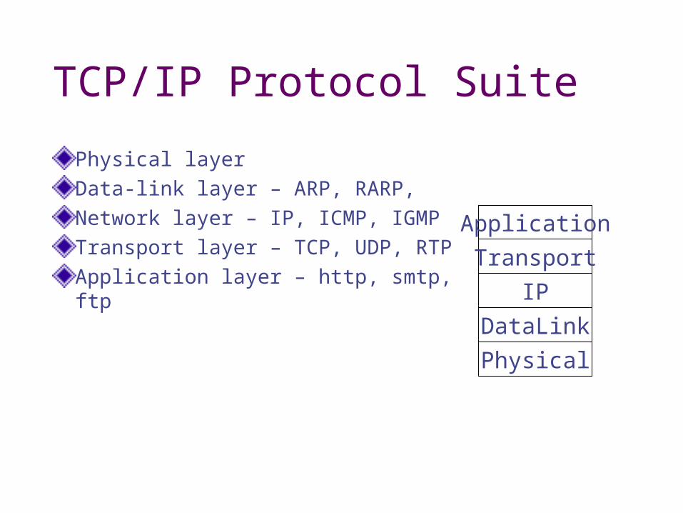
TCP/IP Protocol Suite
IP is used for each network node (or router)
Application
Transport
IP
DataLink
Physical
Application
Transport
IP
DataLink
Physical
IP
DataLink
Physical
IP
DataLink
Physical
Source Dest
Router Router
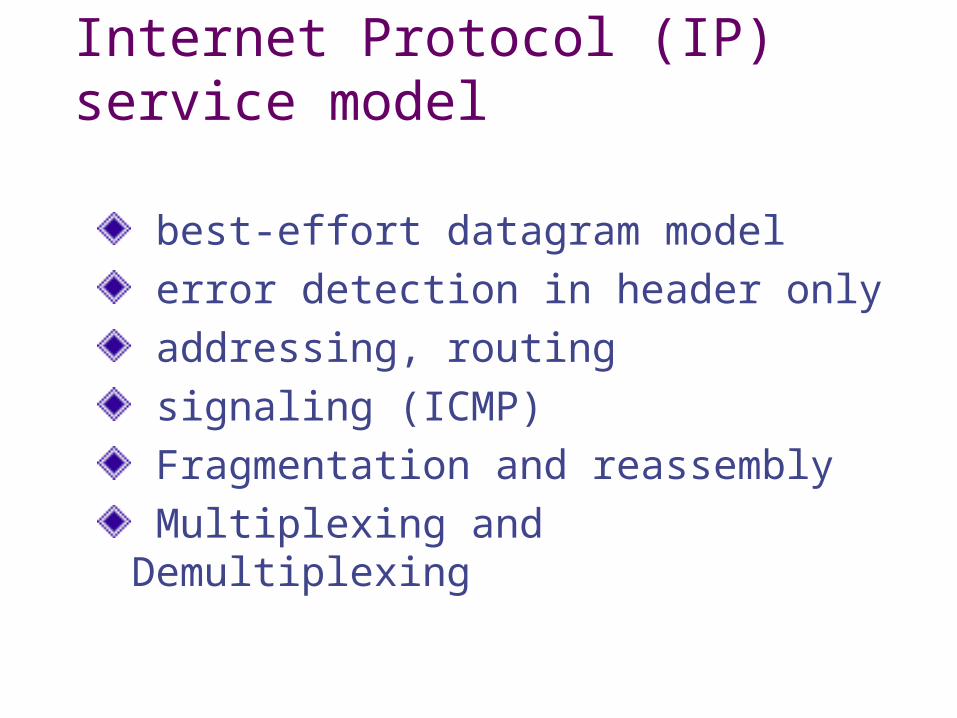
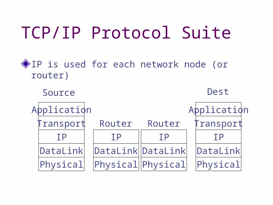
Internet Protocol (IP) service model
best-effort datagram model error detection in header only addressing, routing signaling (ICMP) Fragmentation and reassembly Multiplexing and Demultiplexing
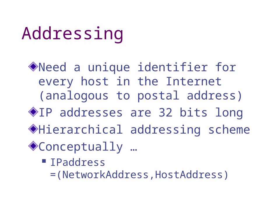
Addressing
Need a unique identifier for every host in the Internet (analogous to postal address)IP addresses are 32 bits longHierarchical addressing schemeConceptually … IPaddress
=(NetworkAddress,HostAddress)
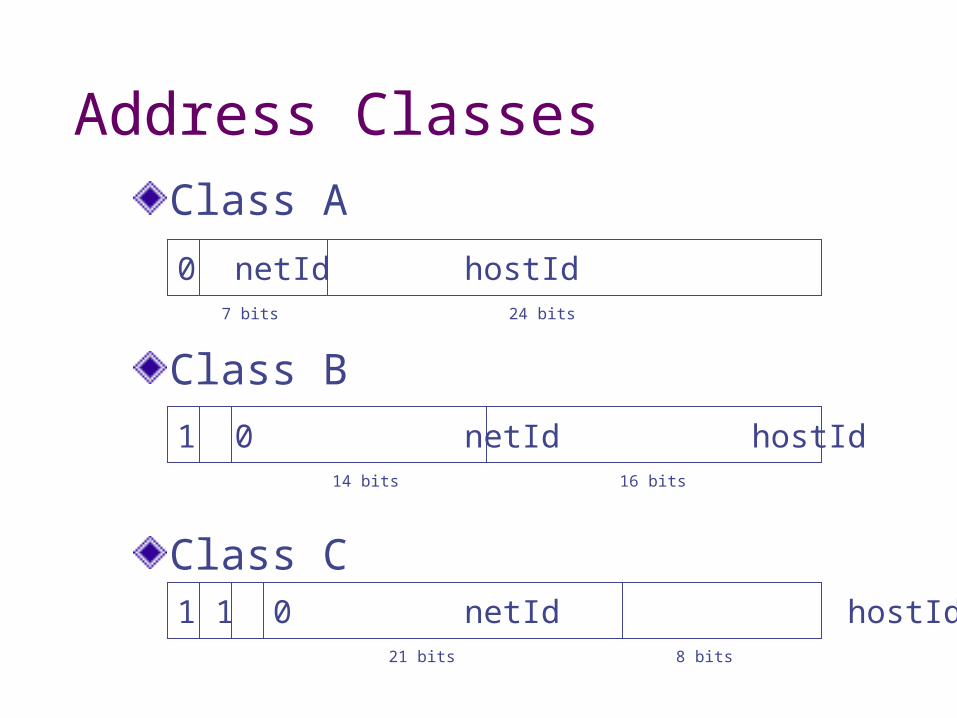
Address ClassesClass A
Class B
Class C
0 netId hostId7 bits 24 bits
1 0 netId hostId14 bits 16 bits
1 1 0 netId hostId21 bits 8 bits
Addresses and Hosts
Since netId is encoded into IP address, each host will have a unique IP address for each of its network connectionsHence, IP addresses refer to network connections and not hostsWhy will hosts have multiple network connections?
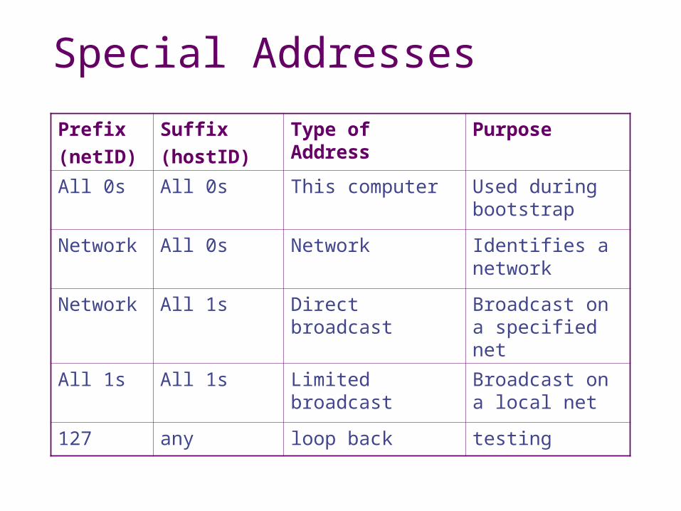
Special Addresses
Prefix(netID)
Suffix(hostID)
Type of Address
Purpose
All 0s All 0s This computer Used during bootstrap
Network All 0s Network Identifies a network
Network All 1s Direct broadcast Broadcast on a specified net
All 1s All 1s Limited broadcast
Broadcast on a local net
127 any loop back testing
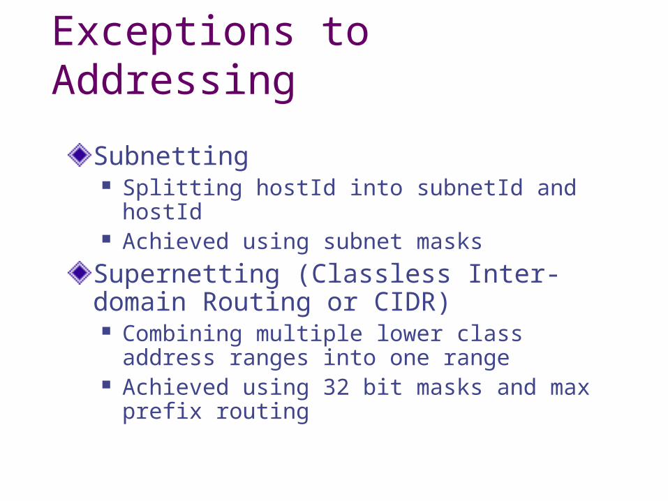
Exceptions to Addressing
Subnetting Splitting hostId into subnetId and hostId Achieved using subnet masks
Supernetting (Classless Inter-domain Routing or CIDR) Combining multiple lower class address
ranges into one range Achieved using 32 bit masks and max prefix
routing
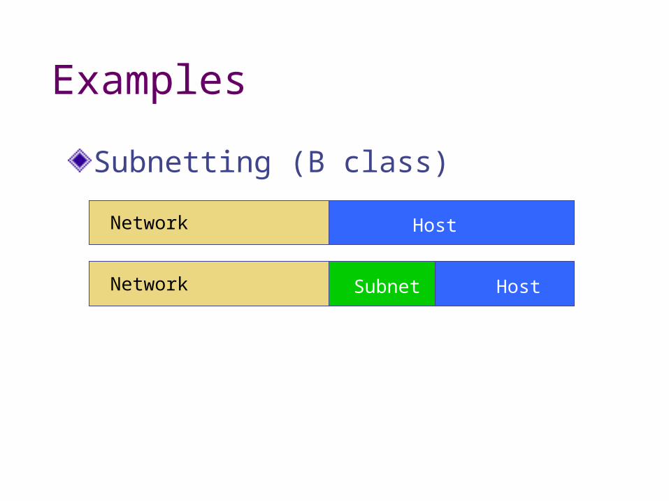
Examples
Subnetting (B class)
Network Host
Network HostSubnet
IP Routing
Direct If source and destination hosts are
connected directly Still need to perform IP address to physical
address translation
Indirect Table driven routing Each entry: (NetId, RouterId)
Default router Host-specific routes
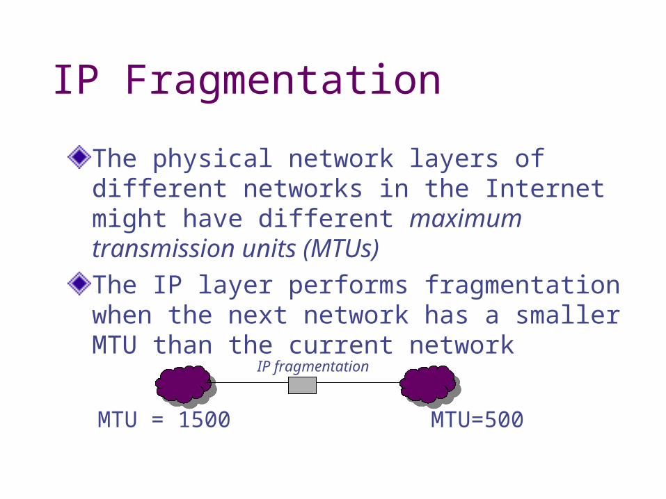
IP Fragmentation
The physical network layers of different networks in the Internet might have different maximum transmission units (MTUs)The IP layer performs fragmentation when the next network has a smaller MTU than the current network
MTU = 1500 MTU=500
IP fragmentation

IP Reassembly
Fragmented packets need to be put together
Where does reassembly occur? The router at the other end of the smaller
MTU network Router overhead: complexity, buffering More than one path
The final destination Many fragments on the path
more chance of missing packets Utilization inefficiency (many headers)
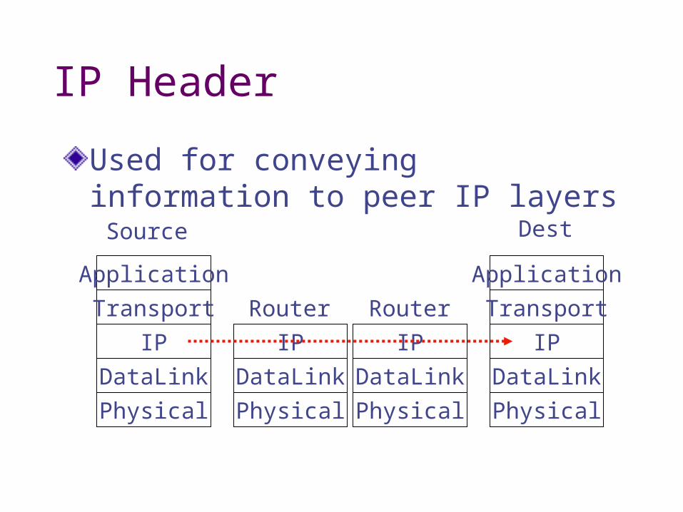
IP Header
Used for conveying information to peer IP layers
Application
Transport
IP
DataLink
Physical
Application
Transport
IP
DataLink
Physical
IP
DataLink
Physical
IP
DataLink
Physical
Source Dest
Router Router
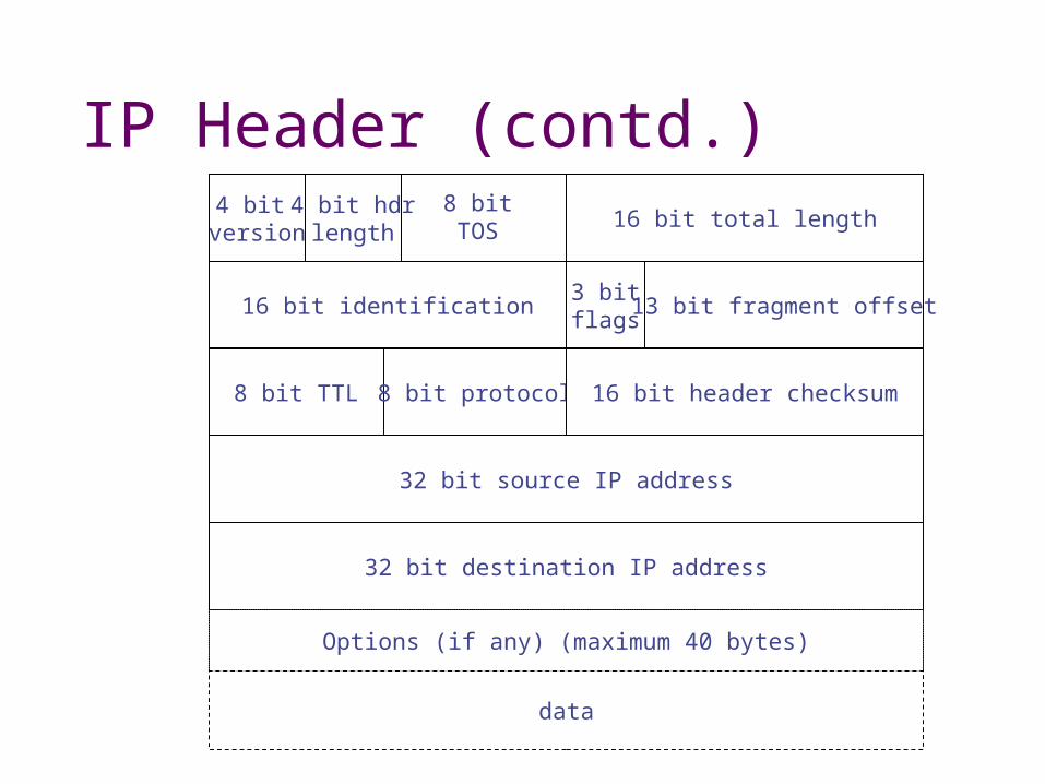
IP Header (contd.)16 bit total length
4 bit version
4 bit hdrlength
16 bit identification
8 bit TTL 8 bit protocol 16 bit header checksum
3 bitflags
32 bit source IP address
32 bit destination IP address
13 bit fragment offset
Options (if any) (maximum 40 bytes)
data
8 bitTOS
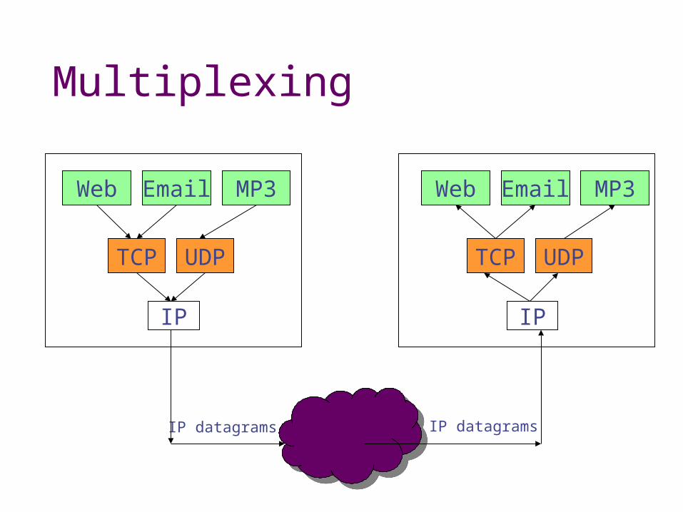
Multiplexing
Web Email MP3
TCP UDP
IP
Web Email MP3
TCP UDP
IP
IP datagrams IP datagrams
Endpoint identification
how to identify a remote application/service on the Internet? [IP_address, port number, protocol] expect to find a process listening for incoming packets
Port numbers
port numbers are in range [0..64K-1] ports below 1024 are known as well-known ports and reserved by IANA ports in range [1024..64K-1] may be registered but are not enforced
User datagram protocol (UDP)
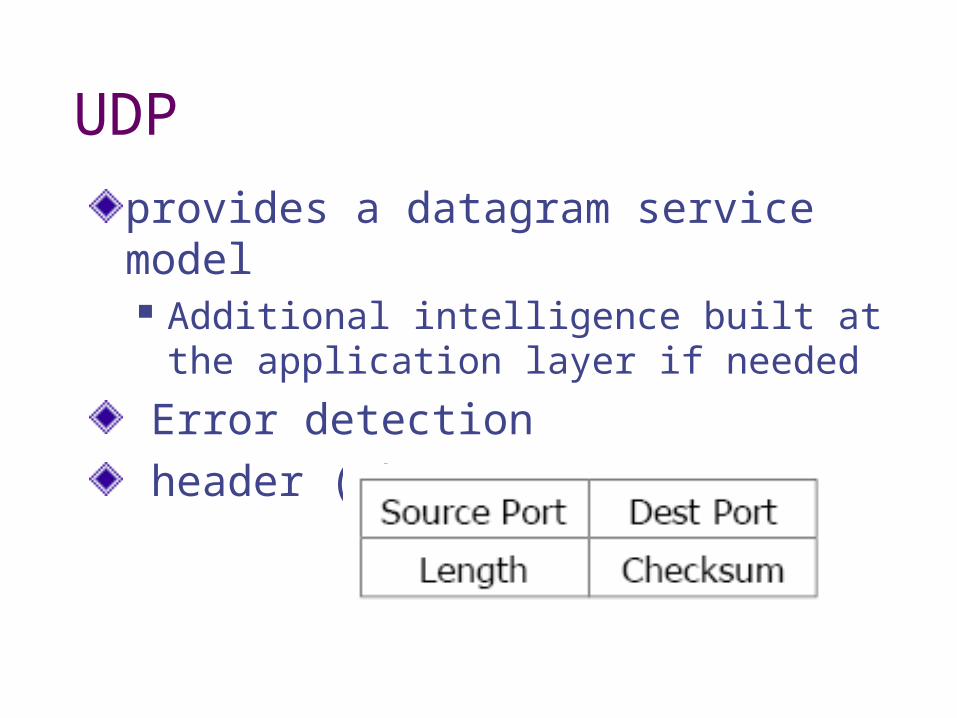
UDP
provides a datagram service model Additional intelligence built at the
application layer if needed
Error detection header (8bytes)
Sending a UDP datagram
application requires that dest IP address, port number to send application chooses message size, requests send using API (e.g. sockets) API allocates OS-level buffer, leaving for some headers, copies data from user-level buffer to OS-level buffer, gives to UDP module

Sending a UDP datagram UDP module receives data and prepends IP and UDP headers fills in IP header info proto, len, src, dst,…
fills in UDP header src_port, dst_port, len,…
sets TTL and TOS sends UDP/IP packet to IP module
UDPheader
IP headerEthernetheader
Application dataEthernet trailer

Sending a UDP datagram
IP module receives packet insert options if enabled sets IP vers, IHL, offset, ID fields determines an interface/MTU fragments if needed and sends to link layer
Receiving a UDP datagram
network adapter receives a frame, interrupts processor device driver determines frame contains IP type data, strips link layer header and gives to IP module IP checks IP header, processes options IP checks IP address (unicast, multicast, …) IP reassembles if necessary, give the whole packet to UDP based on protocol field
Receiving a UDP datagram
UDP receives IP/UDP packet checks length and checksum locates OS PCB based on dest port, providing receiving process’ ID; generates ICMP unreachable if nobody there copies to receiving process’ buffer makes receiving process get to this
*PCB: protocol control block

Why use UDP? downsides no error correction No flow control No congestion control App picks packet size
upsides No connection establishment
stateless Broadcast/multicast more straight forward App picks packet size
Transmission Control Protocol (TCP)
TCP
End-to-end transport protocolResponsible for reliability, congestion control, flow control, and sequenced deliveryApplications that use TCP: http (web), telnet, ftp (file transfer), smtp (email), chatApplications that don’t: multimedia (typically) – use UDP instead
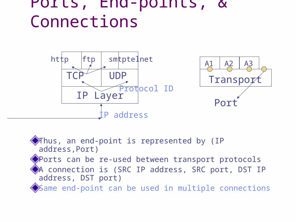
Ports, End-points, & Connections
Thus, an end-point is represented by (IP address,Port)Ports can be re-used between transport protocolsA connection is (SRC IP address, SRC port, DST IP address, DST port)Same end-point can be used in multiple connections
IP Layer
TCP UDP
http ftp smtptelnet
IP address
Protocol ID
A1 A2 A3
Transport
Port

TCP
Connection EstablishmentConnection Maintenance Reliability
by acknowledgement packet (ACK) Congestion control Flow control Sequencing
Connection Termination
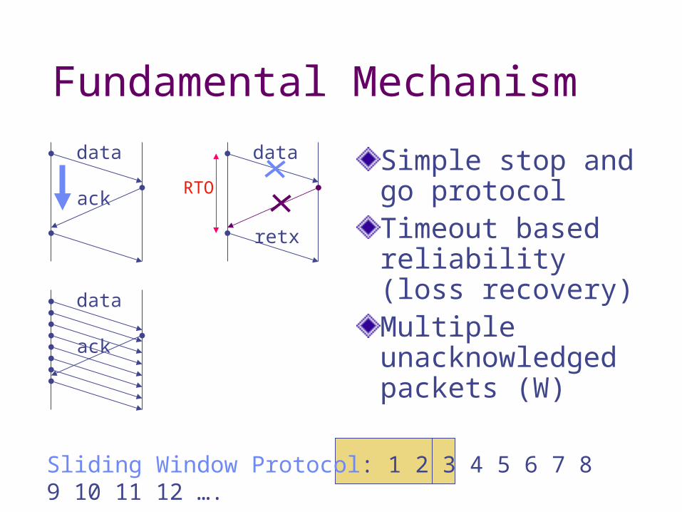
Fundamental Mechanism
Simple stop and go protocolTimeout based reliability (loss recovery)Multiple unacknowledged packets (W)
data
retx
ack
data
ack
data
Sliding Window Protocol: 1 2 3 4 5 6 7 8 9 10 11 12 ….
RTO
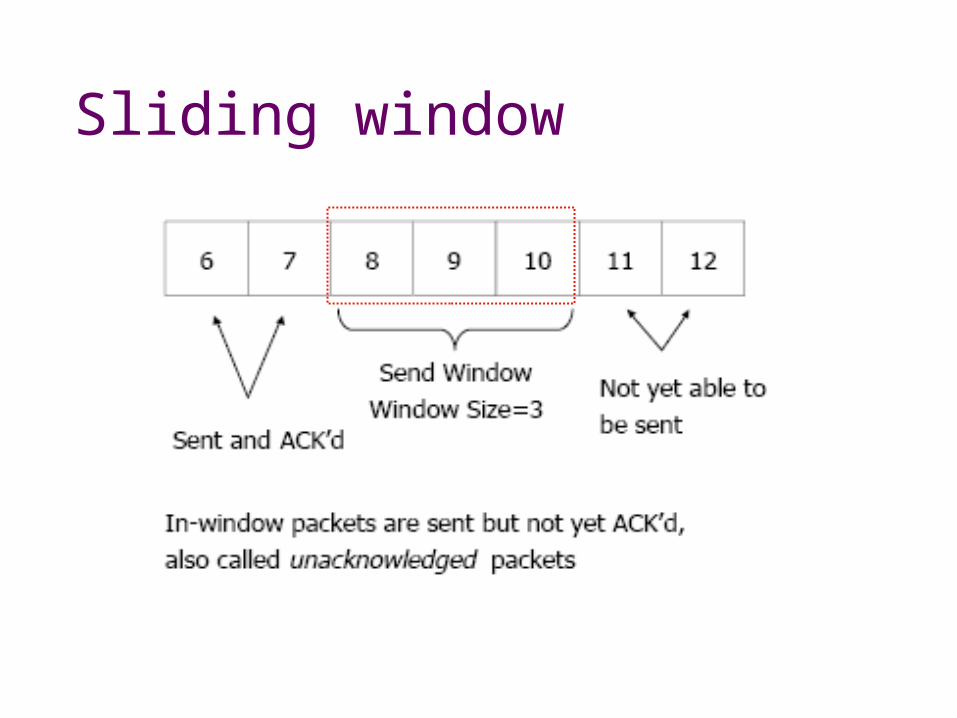
Sliding window
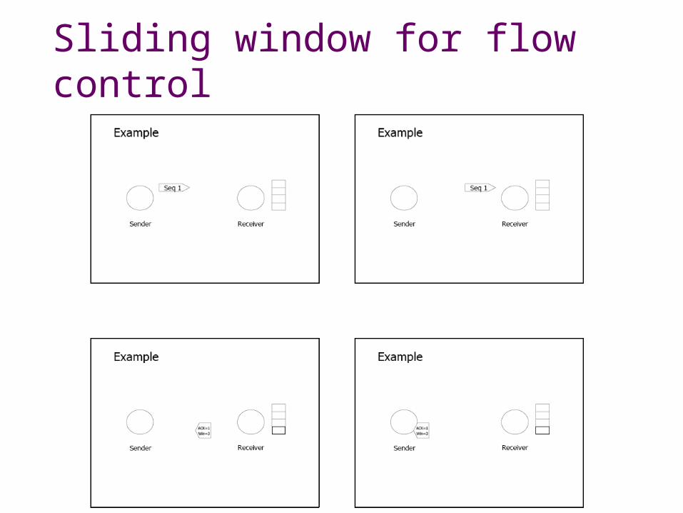
Sliding window for flow control

Sliding window
The sender cannot send more data

Active and Passive Open
How do applications initiate a connection?One end (server) registers with the TCP layer instructing it to “accept” connections at a certain portThe other end (client) initiates a “connect” request which is “accept”-ed by the server

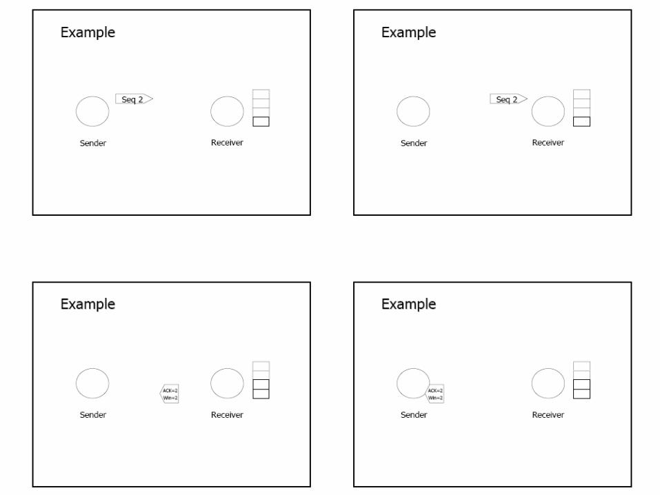
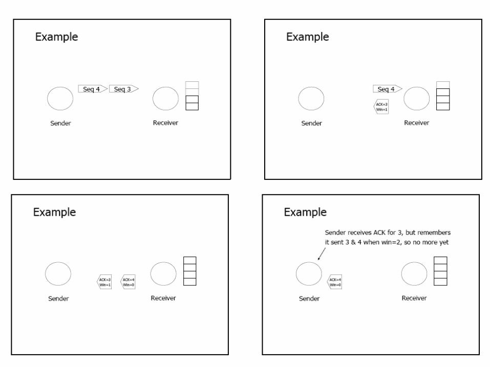
Reliability (Loss Recovery)Sequence NumbersTCP uses cumulative Acknowledgments (ACKs)
Next expected in-sequence packet sequence number
Pros and cons? Piggybacking
Timeout calculation Rttavg = k*Rttavg + (1-k)*Rttsample
RTO = Rttavg + 4*Rttdeviation
ack
data
3
1234
3
34
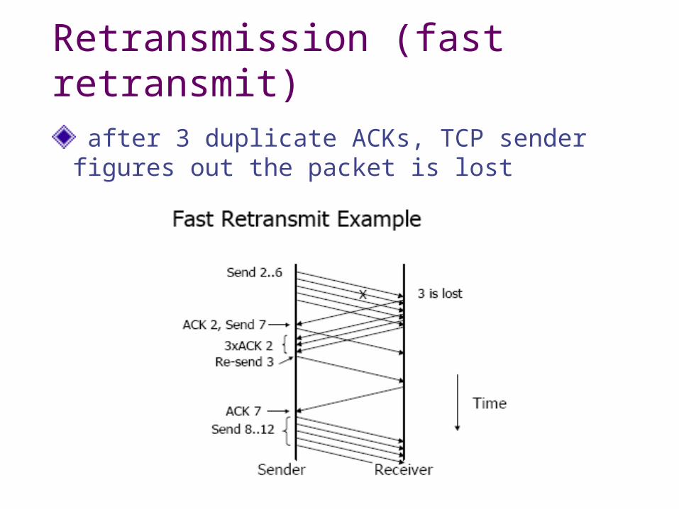
Retransmission (fast retransmit)
after 3 duplicate ACKs, TCP sender figures out the packet is lost
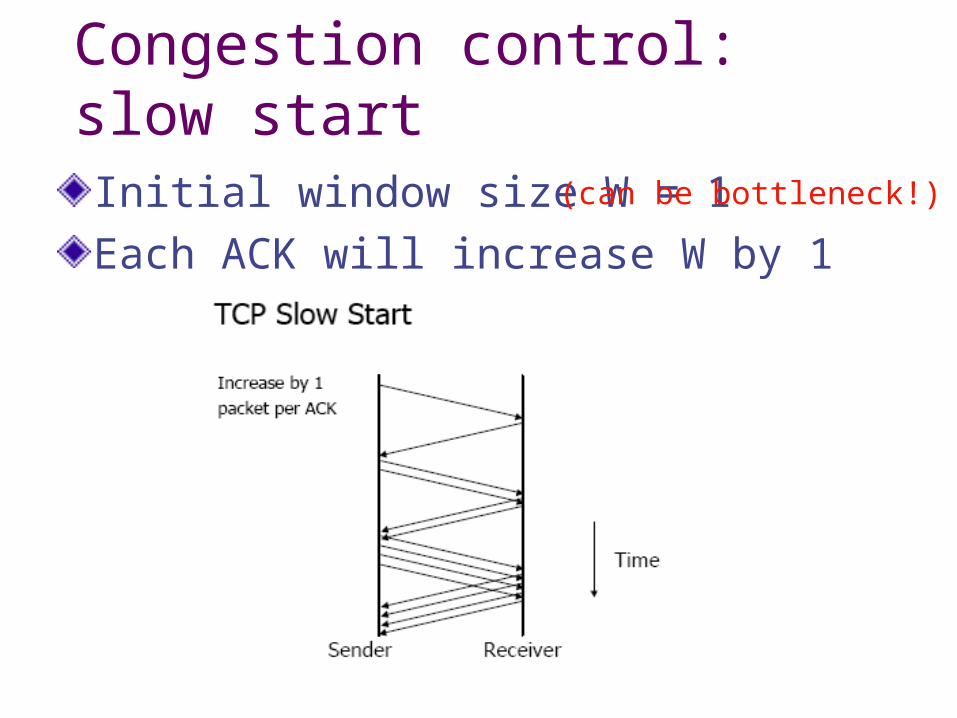
Congestion control: slow startInitial window size W = 1Each ACK will increase W by 1
(can be bottleneck!)
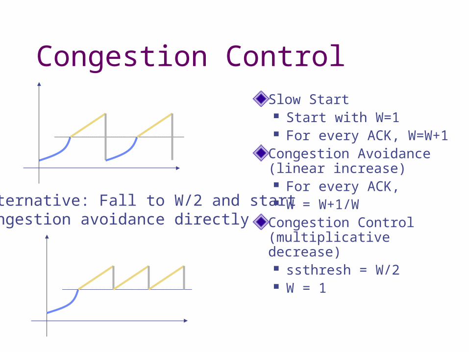
Congestion ControlSlow Start Start with W=1 For every ACK,
W=W+1Congestion Avoidance (linear increase) For every ACK, W = W+1/W
Congestion Control (multiplicative decrease) ssthresh = W/2 W = 1
Alternative: Fall to W/2 and startcongestion avoidance directly
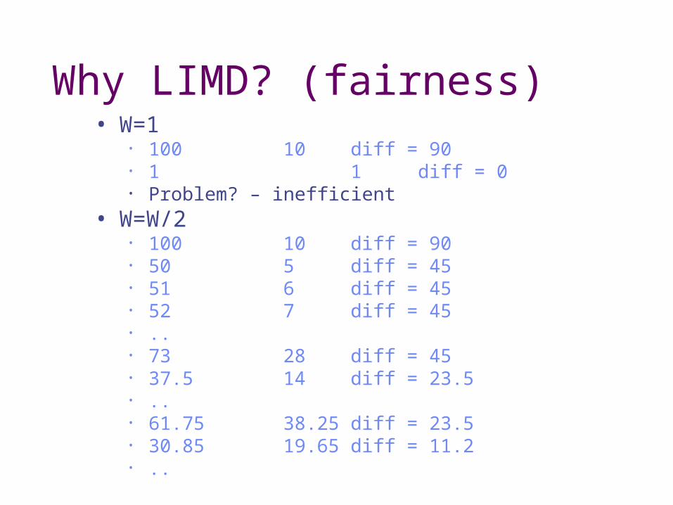
Why LIMD? (fairness)• W=1
• 100 10 diff = 90• 1 1 diff = 0• Problem? – inefficient
• W=W/2• 100 10 diff = 90• 50 5 diff = 45• 51 6 diff = 45• 52 7 diff = 45• ..• 73 28 diff = 45• 37.5 14 diff = 23.5• ..• 61.75 38.25 diff = 23.5• 30.85 19.65 diff = 11.2• ..
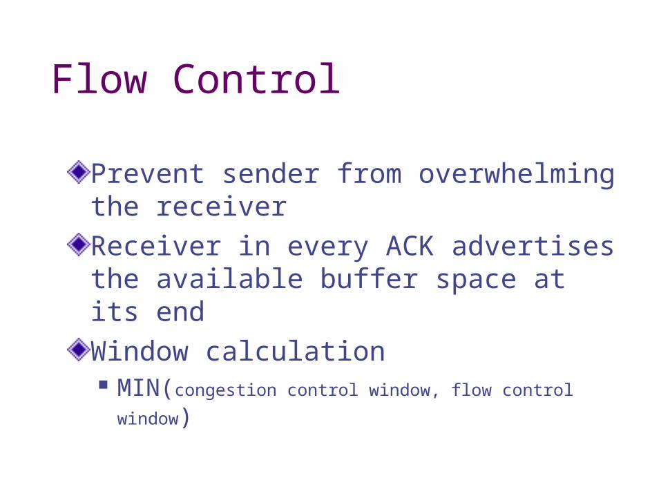
Flow Control
Prevent sender from overwhelming the receiverReceiver in every ACK advertises the available buffer space at its endWindow calculation MIN(congestion control window, flow control window)
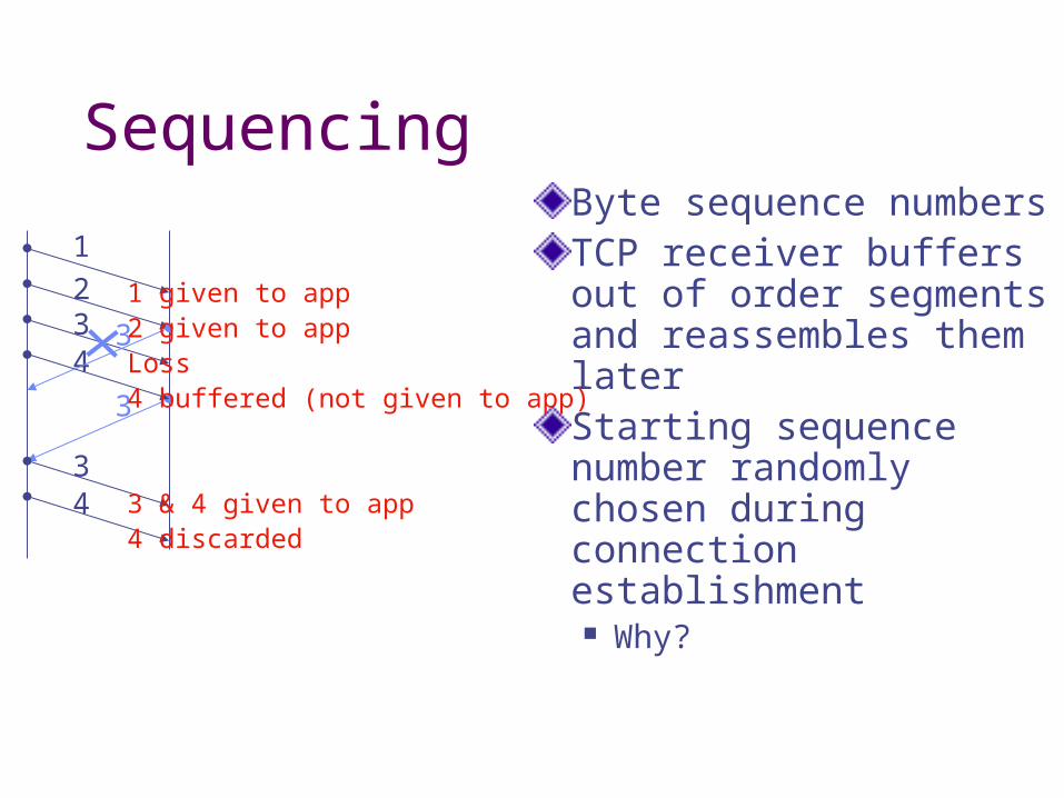
SequencingByte sequence numbersTCP receiver buffers out of order segments and reassembles them laterStarting sequence number randomly chosen during connection establishment Why?
3
1234
3
34
1 given to app2 given to appLoss4 buffered (not given to app)
3 & 4 given to app4 discarded

Connection Establishment & Termination
3-way handshake used for connection establishment Delay!
Randomly chosen sequence number (why?) is conveyed to the other endSimilar FIN, FIN+ACK exchange used for connection termination
SYN
SYN+ACK
ACK
DATA
Server does passive open
Accept connection requestSend acceptance
Start connection
Active openSend connectionrequest

TCP Segment Format
HL
16 bit SRC Port 16 bit DST Port
32 bit sequence number
32 bit ACK number
16 bit window sizeRsv’d flags
16 bit urgent pointer16 bit TCP checksum
Options (if any)
Data
Flags: URG, ACK, PSH, RST, SYN,FIN
Silly window syndrome (SWS)
TCP is a window-based protocolTCP receiver advertises a small amount of window; so TCP sender transmits only a short packet each timeInefficient utilization of network BWSo what? Save up enough to send

Nagle’s algorithm
Buffer all user data if any unacknowledged data is outstandingOk to send if all is ACK’d or have a MSS size worth of dataIf small delay is wanted, Nagle’s algorithm should be disabledMSS size: maximum TCP payload size
MTU: maximum PDU size supported by link layerMTU = MSS + 20 (TCP header) + 20 (IP header)
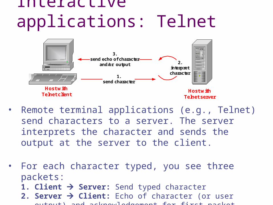
Interactive applications: Telnet
• Remote terminal applications (e.g., Telnet) send characters to a server. The server interprets the character and sends the output at the server to the client.
• For each character typed, you see three packets:1. Client Server: Send typed character 2. Server Client: Echo of character (or user output) and
acknowledgement for first packet3. Client Server: Acknowledgement for second packet
1.send character
2.interpretcharacter
3.send echo of character
and/or output
Host withTelnet client
Host withTelnet server
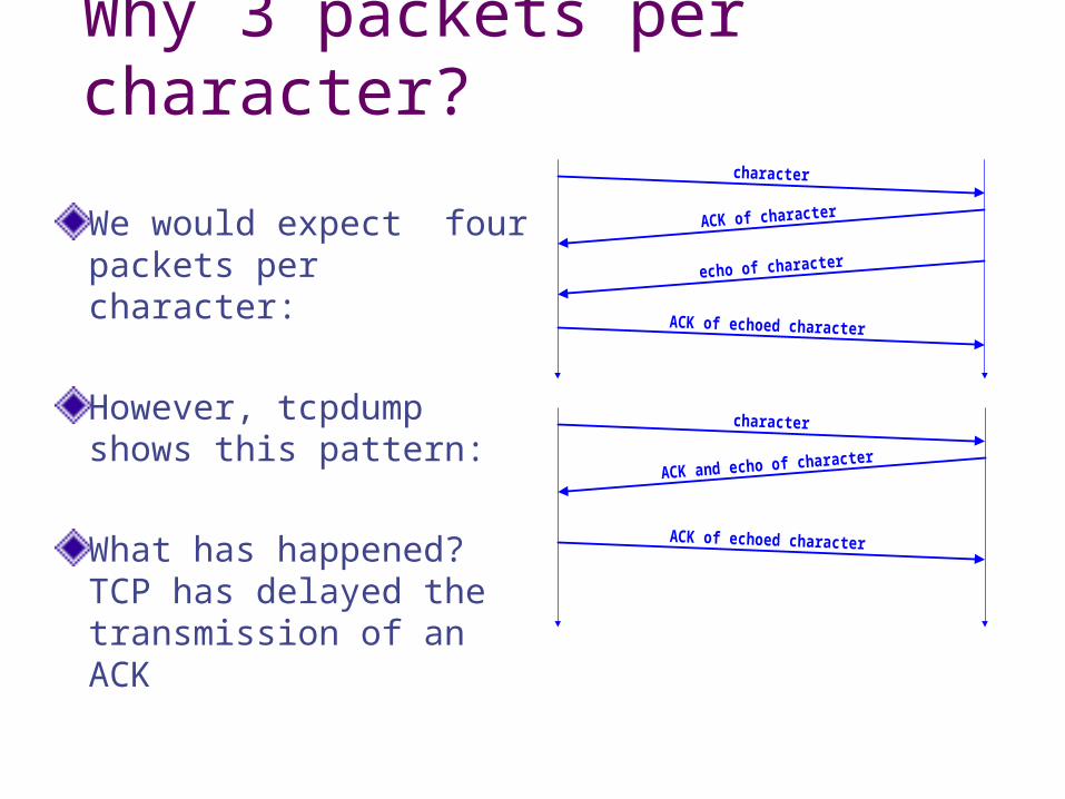
Why 3 packets per character?
We would expect four packets per character:
However, tcpdump shows this pattern:
What has happened? TCP has delayed the transmission of an ACK
character
ACK of character
ACK of echoed character
echo of character
character
ACK and echo of character
ACK of echoed character
Delayed ACKSProblem: In request/response programs, you send
separate ACK and Data packets for each transaction
Solution: Don’t ACK data immediately Wait 200ms (must be less than 500ms –
why?) Must ACK every other packet Must not delay duplicate ACKs
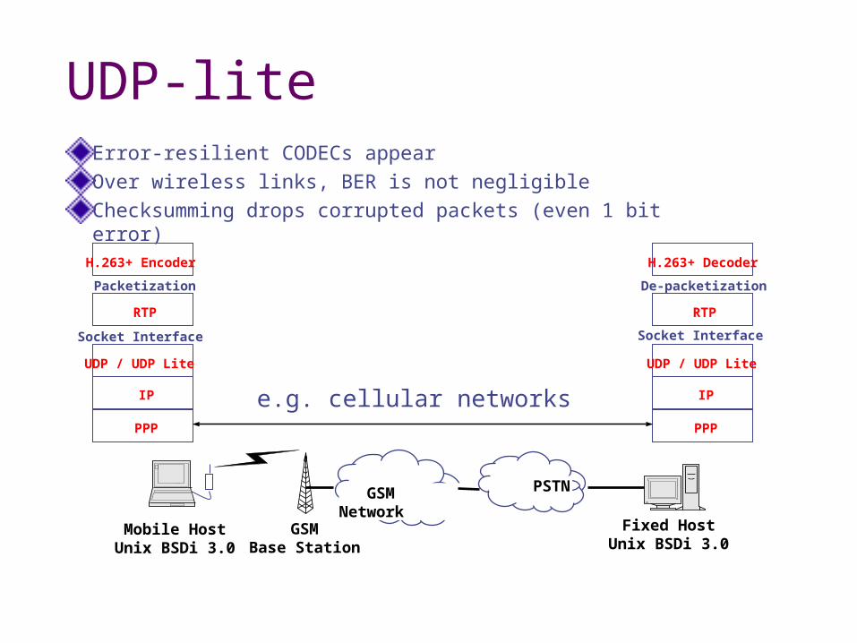
UDP-liteError-resilient CODECs appearOver wireless links, BER is not negligibleChecksumming drops corrupted packets (even 1 bit error)
UDP / UDP Lite
Socket Interface
H.263+ Encoder
RTP
IP
PPP
Packetization
RTP
UDP / UDP Lite
IP
PPP
De-packetization
H.263+ Decoder
Socket Interface
e.g. cellular networks
Fixed HostUnix BSDi 3.0
GSMBase Station
GSM Network PSTN
Mobile HostUnix BSDi 3.0
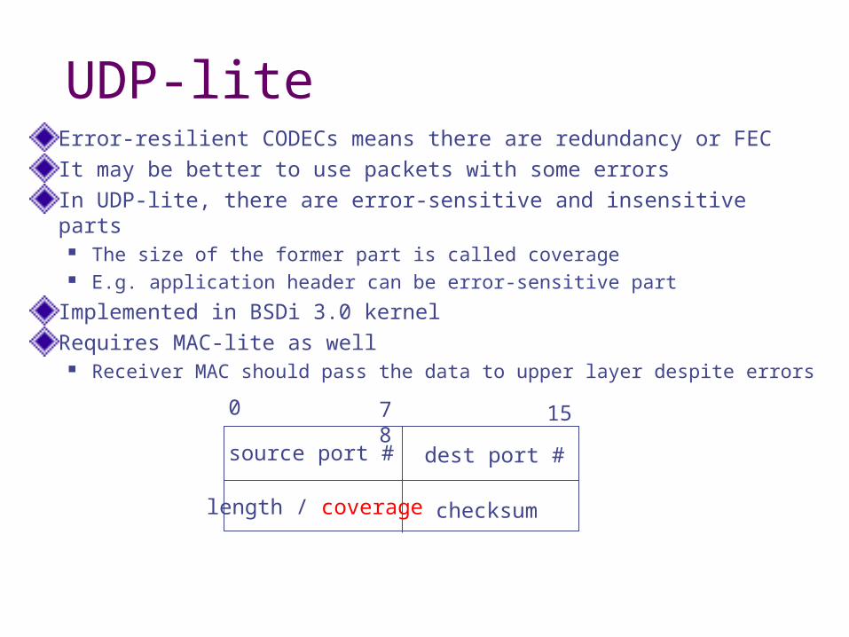
UDP-liteError-resilient CODECs means there are redundancy or FECIt may be better to use packets with some errorsIn UDP-lite, there are error-sensitive and insensitive parts
The size of the former part is called coverage E.g. application header can be error-sensitive part
Implemented in BSDi 3.0 kernel Requires MAC-lite as well
Receiver MAC should pass the data to upper layer despite errors
source port # dest port #
length / coverage checksum
0 7 8 15