Embed Size (px)
Citation preview
8/9/2019 TCPIP Routing Tutorial
http://slidepdf.com/reader/full/tcpip-routing-tutorial 1/22
March 2002
TCP/IP and IPX routing
Tutorial
8/9/2019 TCPIP Routing Tutorial
http://slidepdf.com/reader/full/tcpip-routing-tutorial 2/22
TCP/IP and IPX Routing Tutorial (C)Sangoma Technologies1999,2000,2001,2002 Page 2
"It don't mean a thing if you cain't get that Ping...."Duke Ellington, 1932
Introduction
This tutorial is intended to supply enough information to set up a relatively simple WAN or
Internet-connected LAN using WANPIPE™ WAN router cards or other routers. Explanations of
IP addresses, classes, netmasks, subnetting, and routing are provided, and several examplenetworks are considered. Example address and routing configurations are provided for running
WANPIPE™ WAN router cards under Linux, Unix, and Microsoft platforms.
A basic explanation of IPX routing is also included.
All brand names and product names are trademarks of their respective companies.
The IP Address and Classes
Hosts and networks
IP addressing is based on the concept of hosts and networks. A host is essentially anything on
the network that is capable of receiving and transmitting IP packets on the network, such as aworkstation or a router. It is not to be confused with a server: servers and client workstations are
all IP hosts.
The hosts are connected together by one or more networks. The IP address of any host consistsof its network address plus its own host address on the network. IP addressing, unlike, say, IPXaddressing, uses one address containing both network and host address.
How much of the address is used for the network portion and how much for the host portionvaries from network to network.
IP addressing
An IP address is 32 bits wide, and as discussed, it is composed of two parts: the network
number, and the host number [1, 2, 3]. By convention, it is expressed as four decimal numbers
separated by periods, such as "200.1.2.3" representing the decimal value of each of the fourbytes. Valid addresses thus range from 0.0.0.0 to 255.255.255.255, a total of about 4.3 billion
addresses. The first few bits of the address indicate the Class that the address belongs to:
8/9/2019 TCPIP Routing Tutorial
http://slidepdf.com/reader/full/tcpip-routing-tutorial 3/22
TCP/IP and IPX Routing Tutorial (C)Sangoma Technologies1999,2000,2001,2002 Page 3
Class Prefix Network Number Host Number
A 0 Bits 0-7 Bits 8-31
B 10 Bits 1-15 Bits 16-31
C 110 Bits 2-24 Bits 25-31
D 1110 N/AE 1111 N/A
The bits are labeled in network order, so that the first bit is bit 0 and the last is bit 31, reading
from left to right. Class D addresses are multicast, and Class E is reserved. The range of network
numbers and host numbers may then be derived:
Class Range of Net Numbers Range of Host Numbers
A 0 to 126 0.0.1 to 255.255.254
B 128.0 to 191.255 0.1 to 255.254
C 192.0.0 to 254.255.255 1 to 254
Any address starting with 127 is a loop back address and should never be used for addressingoutside the host. A host number of all binary 1's indicates a directed broadcast over the specific
network. For example, 200.1.2.255 would indicate a broadcast over the 200.1.2 network. If the
host number is 0, it indicates "this host". If the network number is 0, it indicates "this network"[2].
All the reserved bits and reserved addresses severely reduce the available IP addresses from the4.3 billion theoretical maximum. Most users connected to the Internet will be assigned addresses
within Class C, as space is becoming very limited. This is the primary reason for the
development of IPv6, which will have 128 bits of address space.
Basic IP Routing
Classed IP Addressing and the Use of ARP
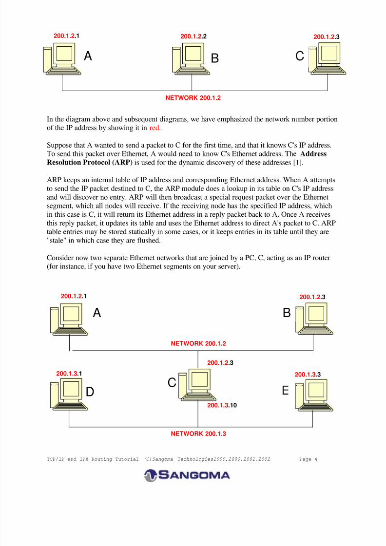
Consider a small internal TCP/IP network consisting of one Ethernet segment and three nodes.
The IP network number of this Ethernet segment is 200.1.2. The host numbers for A, B, and Care 1, 2, and 3 respectively. These are Class C addresses, and therefore allow for up to 254 nodes
on this network segment.
Each of these nodes has corresponding Ethernet addresses, which are six bytes long. They are
normally written in hexadecimal form separated by dashes (02-FE-87-4A-8C-A9 for example).
8/9/2019 TCPIP Routing Tutorial
http://slidepdf.com/reader/full/tcpip-routing-tutorial 4/22
TCP/IP and IPX Routing Tutorial (C)Sangoma Technologies1999,2000,2001,2002 Page 4
In the diagram above and subsequent diagrams, we have emphasized the network number portionof the IP address by showing it in red.
Suppose that A wanted to send a packet to C for the first time, and that it knows C's IP address.To send this packet over Ethernet, A would need to know C's Ethernet address. The Address
Resolution Protocol (ARP) is used for the dynamic discovery of these addresses [1].
ARP keeps an internal table of IP address and corresponding Ethernet address. When A attempts
to send the IP packet destined to C, the ARP module does a lookup in its table on C's IP addressand will discover no entry. ARP will then broadcast a special request packet over the Ethernetsegment, which all nodes will receive. If the receiving node has the specified IP address, which
in this case is C, it will return its Ethernet address in a reply packet back to A. Once A receives
this reply packet, it updates its table and uses the Ethernet address to direct A's packet to C. ARPtable entries may be stored statically in some cases, or it keeps entries in its table until they are
"stale" in which case they are flushed.
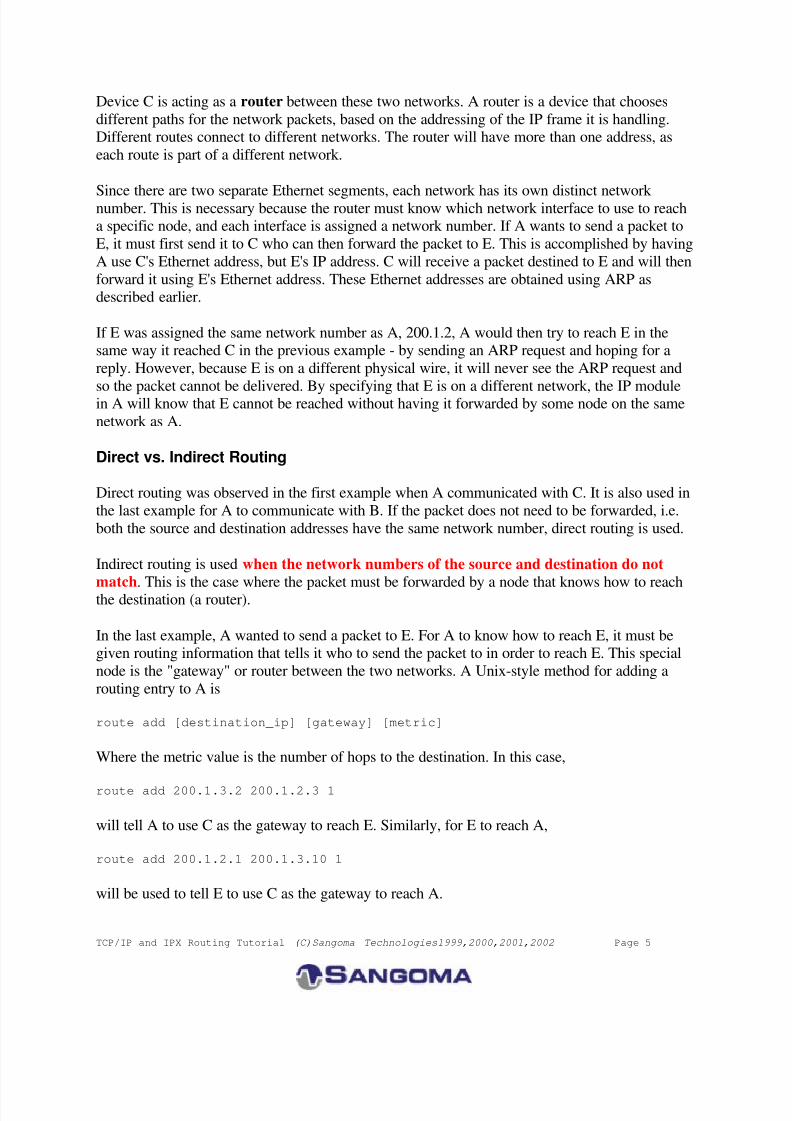
Consider now two separate Ethernet networks that are joined by a PC, C, acting as an IP router(for instance, if you have two Ethernet segments on your server).
200.1.2.3
NETWORK 200.1.2
200.1.2.1 200.1.2.2
A B C
200.1.3.10
NETWORK 200.1.3
NETWORK 200.1.2
200.1.2.1
200.1.2.3
200.1.2.3
200.1.3.3
A B
C
200.1.3.1
D
8/9/2019 TCPIP Routing Tutorial
http://slidepdf.com/reader/full/tcpip-routing-tutorial 5/22
TCP/IP and IPX Routing Tutorial (C)Sangoma Technologies1999,2000,2001,2002 Page 5
Device C is acting as a router between these two networks. A router is a device that chooses
different paths for the network packets, based on the addressing of the IP frame it is handling.Different routes connect to different networks. The router will have more than one address, as
each route is part of a different network.
Since there are two separate Ethernet segments, each network has its own distinct network number. This is necessary because the router must know which network interface to use to reacha specific node, and each interface is assigned a network number. If A wants to send a packet to
E, it must first send it to C who can then forward the packet to E. This is accomplished by having
A use C's Ethernet address, but E's IP address. C will receive a packet destined to E and will then
forward it using E's Ethernet address. These Ethernet addresses are obtained using ARP asdescribed earlier.
If E was assigned the same network number as A, 200.1.2, A would then try to reach E in thesame way it reached C in the previous example - by sending an ARP request and hoping for a
reply. However, because E is on a different physical wire, it will never see the ARP request and
so the packet cannot be delivered. By specifying that E is on a different network, the IP modulein A will know that E cannot be reached without having it forwarded by some node on the same
network as A.
Direct vs. Indirect Routing
Direct routing was observed in the first example when A communicated with C. It is also used in
the last example for A to communicate with B. If the packet does not need to be forwarded, i.e.
both the source and destination addresses have the same network number, direct routing is used.
Indirect routing is used when the network numbers of the source and destination do not
match. This is the case where the packet must be forwarded by a node that knows how to reachthe destination (a router).
In the last example, A wanted to send a packet to E. For A to know how to reach E, it must begiven routing information that tells it who to send the packet to in order to reach E. This special
node is the "gateway" or router between the two networks. A Unix-style method for adding a
routing entry to A is
route add [destination_ip] [gateway] [metric]
Where the metric value is the number of hops to the destination. In this case,
route add 200.1.3.2 200.1.2.3 1
will tell A to use C as the gateway to reach E. Similarly, for E to reach A,
route add 200.1.2.1 200.1.3.10 1
will be used to tell E to use C as the gateway to reach A.
8/9/2019 TCPIP Routing Tutorial
http://slidepdf.com/reader/full/tcpip-routing-tutorial 6/22
TCP/IP and IPX Routing Tutorial (C)Sangoma Technologies1999,2000,2001,2002 Page 6
It is necessary that C have two IP addresses - one for each network interface. This way, A knows
from C's IP address that it is on its own network, and similarly for E. Within C, the routingmodule will know from the network number of each interface which one to use for forwarding IP
packets.
In most cases it will not be necessary to manually add this routing entry. It would normally besufficient to set up C as the default gateway for all other nodes on both networks. The defaultgateway is the IP address of the machine to send all packets to that are not destined to a node on
the directly-connected network. The routing table in the default gateway will be set up to forward
the packets properly, which will be discussed in detail later.
Static vs. Dynamic Routing
Static routing is performed using a preconfigured routing table, which remains in effect
indefinitely, unless the user changes it manually. This is the most basic form of routing, and it
usually requires that all machines have statically configured addresses, and definitely requires
that all machines remain on their respective networks. Otherwise, the user must manually alterthe routing tables on one or more machines to reflect the change in network topology or
addressing. Usually at least one static entry exists for the network interface, and is normallycreated automatically when the interface is configured.
Dynamic routing uses special routing information protocols to automatically update the routingtable with routes known by peer routers. These protocols are grouped according to whether they
are Interior Gateway Protocols (IGPs) or Exterior Gateway Protocols. Interior gateway protocols
are used to distribute routing information inside of an Autonomous System (AS). An AS is a set
of routers inside the domain administered by one authority. Examples of interior gatewayprotocols are OSPF and RIP. Exterior gateway protocols are used for inter-AS routing, so that
each AS may be aware of how to reach others throughout the Internet. Examples of exteriorgateway protocols are EGP and BGP. See RFC 1716 [11] for more information on IP routeroperations.
WANPIPE™ Routing
WANPIPE™ is a network interface, and does not actually route packets according to IPaddress, or maintain IP routing information. Packet routing between interfaces is actually
handled by the protocol stack, which can send IP based dynamic routing protocols over
WANPIPE™. The information and protocols needed for dynamic routing are also handled by
the protocol stack, and not at the WANPIPE™ level. Where WANPIPE™ is used as a WANgateway for a single LAN it is almost always better to use explicit static routing table entries
rather than having to deal with dynamic routing.
8/9/2019 TCPIP Routing Tutorial
http://slidepdf.com/reader/full/tcpip-routing-tutorial 7/22
TCP/IP and IPX Routing Tutorial (C)Sangoma Technologies1999,2000,2001,2002 Page 7
Advanced IP Routing
The Netmask
When setting up each node with its IP address, the netmask must also be specified. This mask is
used to specify which part of the address is the network number part, and which is the host part.This is accomplished by a logical bitwise-AND between the netmask and the IP address. The
result specifies the network number. For Class C, the netmask will always be 255.255.255.0; for
Class B, the netmask will always be 255.255.0.0; and so on. When A sent a packet to E in thelast example, A knew that E wasn't on its network segment by comparing A's network number
200.1.2 to the value resulting from the bitwise-AND between the netmask 255.255.255.0 and the
IP address of E, 200.1.3.2, which is 200.1.3.
The netmask becomes very important, and more complicated, when "classless" addressing is
used.
Hierarchical Sub-Allocation of Class C Addresses
To make more efficient use of Class C addresses in the Internet community, these addresses are
subnetted hierarchically from the service provider to the organization. They are allocatedbitmask-oriented subsets of the provider's address space [4, 5]. These are classless addresses.
Consider the following example of a small organization consisting of two Ethernet segmentsconnecting to an Internet service provider using a WAN router that emulates an additional
network segment, such as WANPIPE™. The service provider has been allocated several
different Class C addresses to be used for its clients. This particular organization has beenallocated the network number 210.20.30, and the gateway address at the provider end is
210.20.30.254.
8/9/2019 TCPIP Routing Tutorial
http://slidepdf.com/reader/full/tcpip-routing-tutorial 8/22
TCP/IP and IPX Routing Tutorial (C)Sangoma Technologies1999,2000,2001,2002 Page 8
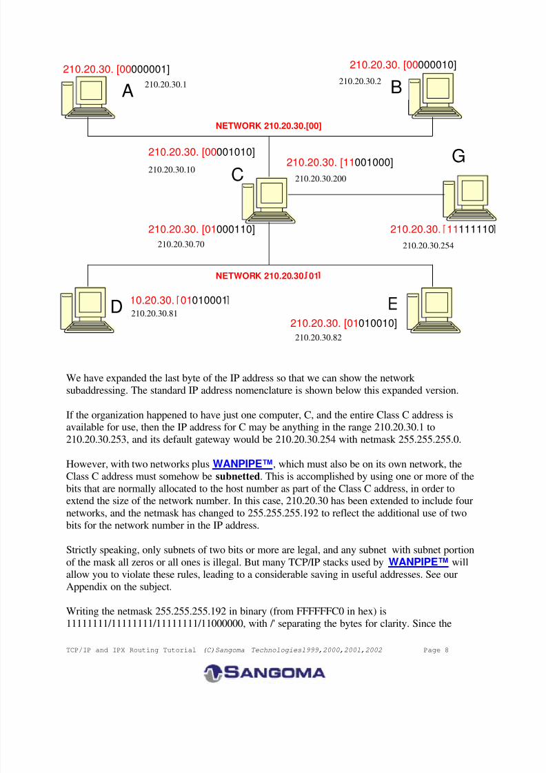
We have expanded the last byte of the IP address so that we can show the network
subaddressing. The standard IP address nomenclature is shown below this expanded version.
If the organization happened to have just one computer, C, and the entire Class C address isavailable for use, then the IP address for C may be anything in the range 210.20.30.1 to
210.20.30.253, and its default gateway would be 210.20.30.254 with netmask 255.255.255.0.
However, with two networks plus WANPIPE™, which must also be on its own network, the
Class C address must somehow be subnetted. This is accomplished by using one or more of the
bits that are normally allocated to the host number as part of the Class C address, in order toextend the size of the network number. In this case, 210.20.30 has been extended to include four
networks, and the netmask has changed to 255.255.255.192 to reflect the additional use of two
bits for the network number in the IP address.
Strictly speaking, only subnets of two bits or more are legal, and any subnet with subnet portion
of the mask all zeros or all ones is illegal. But many TCP/IP stacks used by WANPIPE™ willallow you to violate these rules, leading to a considerable saving in useful addresses. See our
Appendix on the subject.
Writing the netmask 255.255.255.192 in binary (from FFFFFFC0 in hex) is
11111111/11111111/11111111/11000000, with /' separating the bytes for clarity. Since the
210.20.30. 11111110
210.20.30. 01010001
210.20.30.82
NETWORK 210.20.30.[00]
210.20.30. [00000010]
210.20.30. [01010010]
210.20.30. [01000110]
210.20.30. [00001010]
210.20.30. [00000001]
NETWORK 210.20.30. 01
A B
C
210.20.30.1 210.20.30.2
210.20.30.10210.20.30. [11001000]
210.20.30.200
210.20.30.254210.20.30.70
210.20.30.81D
G
8/9/2019 TCPIP Routing Tutorial
http://slidepdf.com/reader/full/tcpip-routing-tutorial 9/22
TCP/IP and IPX Routing Tutorial (C)Sangoma Technologies1999,2000,2001,2002 Page 9
organization is allocated all of 210.20.30 (D2141E hex), it has the use of the four following
network numbers (in binary):
Net# IP Network Number
0 11010010/00010100/00011110/00
1 11010010/00010100/00011110/01
2 11010010/00010100/00011110/10
3 11010010/00010100/00011110/11
This leaves 6 bits at the end to use for host number, leaving space for 62 host nodes per network (all 0's and all 1's are reserved). The following addresses are therefore valid for hosts to use:
Net# Address Range
0 210.20.30.1 to 210.20.30.62
1 210.20.30.65 to 210.20.30.126
2 210.20.30.129 to 210.20.30.190
3 210.20.30.193 to 210.20.30.254
In this example, Net#2 is reserved for future use.The IP addresses and netmasks for each interface are:
Interface IP Address Netmask
Node A 210.20.30.1 255.255.255.192
Node B 210.20.30.2 255.255.255.192
Node C (AB) 210.20.30.10 255.255.255.192
Node C (DE) 210.20.30.70 255.255.255.192
Node C (WAN) 210.20.30.200 255.255.255.192
Node D 210.20.30.81 255.255.255.192
Node E 210.20.30.82 255.255.255.192
The routing tables will be set for each node as follows. The destination address 0.0.0.0 indicatesthe default destination, if no other specific routes are configured for the given packet destination.
This default destination is where all packets will be sent, and it is assumed that this destination is
capable of forwarding these packets to the ultimate destination, or to another router along the
appropriate path.
Node A:
Network Address Netmask Gateway Interface
0.0.0.0 0.0.0.0 210.20.30.10 210.20.30.1
210.20.30.0 255.255.255.192 210.20.30.1 210.20.30.1
Node B:
Network Address Netmask Gateway Interface
0.0.0.0 0.0.0.0 210.20.30.10 210.20.30.2
8/9/2019 TCPIP Routing Tutorial
http://slidepdf.com/reader/full/tcpip-routing-tutorial 10/22
TCP/IP and IPX Routing Tutorial (C)Sangoma Technologies1999,2000,2001,2002 Page 10
210.20.30.0 255.255.255.192 210.20.30.2 210.20.30.2
Node C:
Network Address Netmask Gateway Interface
0.0.0.0 0.0.0.0 210.20.30.254 210.20.30.200
210.20.30.0 255.255.255.192 210.20.30.10 210.20.30.10
210.20.30.64 255.255.255.192 210.20.30.70 210.20.30.70
210.20.30.192 255.255.255.192 210.20.30.200 210.20.30.200
Node D:
Network Address Netmask Gateway Interface
0.0.0.0 0.0.0.0 210.20.30.70 210.20.30.81
210.20.30.64 255.255.255.192 210.20.30.81 210.20.30.81
Node E:
Network Address Netmask Gateway Interface
0.0.0.0 0.0.0.0 210.20.30.70 210.20.30.82
210.20.30.64 255.255.255.192 210.20.30.82 210.20.30.82
Node G:
Network Address Netmask Gateway Interface
210.20.30.0 255.255.255.0 210.20.30.200 210.20.30.254
(Plus all other pertinent entries)
The metric value, or hop count, is optional, but would be 0 for all gateways that are the same asthe hosts, and greater than 0 if the destination is reached via one or more gateways. The metric
for the default routes is indeterminate, but would always be at least 1.
For example, if D sent an ICMP echo request packet out onto the Internet, let's say to address
140.51.120.30, then first D would AND the netmask 255.255.255.192 with 140.51.120.30 to
determine the network number. It would then find that it does not match the network number
210.20.30.64, and so it chooses the default route which points to the gateway 210.20.30.70. Itthen uses the Ethernet address of Node C (DE) to forward the IP packet to the gateway.
When C receives this packet, it will see that it is destined to 140.51.120.30. It checks all the
routes in its table and determines that this address is not located on any of the listed networks in
the routing table, and so it chooses the default route. It uses the WAN interface, of IP address210.20.30.200 to send the packet to 210.20.30.254 (G). From then on, the packet will propagate
from gateway to gateway until it reaches 140.51.120.30. When this node replies, the packet will
be inbound on interface 210.20.30.200 (C) with destination address 210.20.30.81 (D). Node Cwill discover that 210.20.30.81 is on the 210.20.30.64 network and uses the interface
210.20.30.70 to send the packet back home to D.
8/9/2019 TCPIP Routing Tutorial
http://slidepdf.com/reader/full/tcpip-routing-tutorial 11/22
TCP/IP and IPX Routing Tutorial (C)Sangoma Technologies1999,2000,2001,2002 Page 11
TCP/IP Setup Examples by Protocol Stack and Platform
Please note that there are some additional restrictions on IP subnetting addresses that can beused, see the Appendix.
Two examples will be presented to explain how to set up the IP addressing and routinginformation when connecting to an Internet service provider using WANPIPE™. The first caseis when only one machine will be connected, and the other case describes the connection of a
LAN to the Internet. The third example briefly illustrates the addressing and routing techniquesfor connecting two LANs over a point-to-point WAN connection.
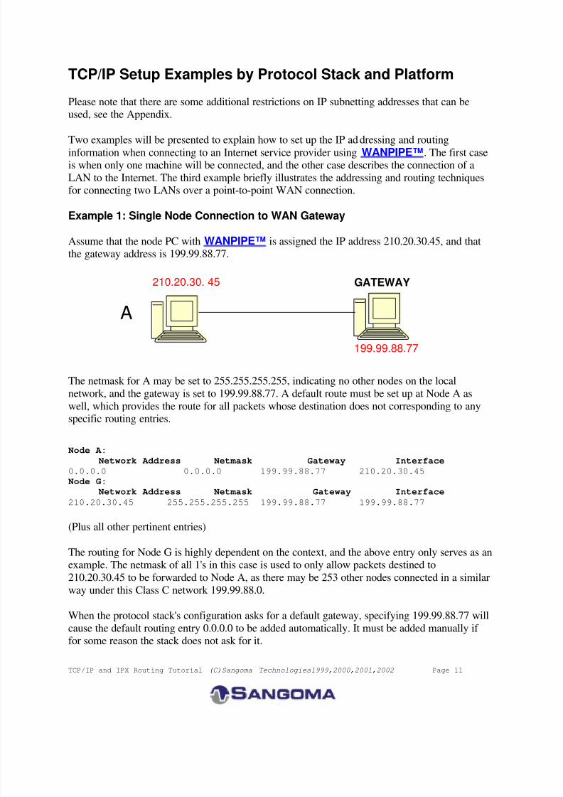
Example 1: Single Node Connection to WAN Gateway
Assume that the node PC with WANPIPE™ is assigned the IP address 210.20.30.45, and thatthe gateway address is 199.99.88.77.
The netmask for A may be set to 255.255.255.255, indicating no other nodes on the local
network, and the gateway is set to 199.99.88.77. A default route must be set up at Node A as
well, which provides the route for all packets whose destination does not corresponding to any
specific routing entries.
Node A:
Network Address Netmask Gateway Interface
0.0.0.0 0.0.0.0 199.99.88.77 210.20.30.45
Node G:
Network Address Netmask Gateway Interface
210.20.30.45 255.255.255.255 199.99.88.77 199.99.88.77
(Plus all other pertinent entries)
The routing for Node G is highly dependent on the context, and the above entry only serves as anexample. The netmask of all 1's in this case is used to only allow packets destined to
210.20.30.45 to be forwarded to Node A, as there may be 253 other nodes connected in a similar
way under this Class C network 199.99.88.0.
When the protocol stack's configuration asks for a default gateway, specifying 199.99.88.77 will
cause the default routing entry 0.0.0.0 to be added automatically. It must be added manually if for some reason the stack does not ask for it.
199.99.88.77
210.20.30. 45
A
GATEWAY
8/9/2019 TCPIP Routing Tutorial
http://slidepdf.com/reader/full/tcpip-routing-tutorial 12/22
TCP/IP and IPX Routing Tutorial (C)Sangoma Technologies1999,2000,2001,2002 Page 12
The specific methods of configuring each protocol stack will be explained in detail in Example 2.
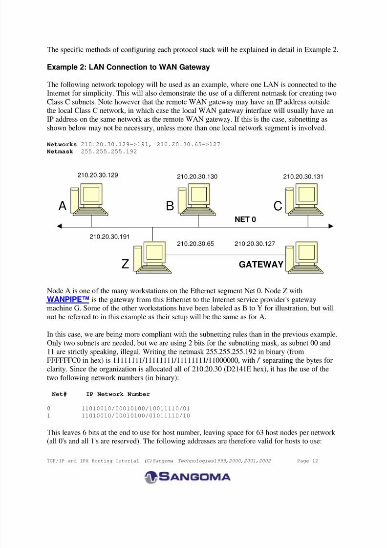
Example 2: LAN Connection to WAN Gateway
The following network topology will be used as an example, where one LAN is connected to the
Internet for simplicity. This will also demonstrate the use of a different netmask for creating twoClass C subnets. Note however that the remote WAN gateway may have an IP address outsidethe local Class C network, in which case the local WAN gateway interface will usually have an
IP address on the same network as the remote WAN gateway. If this is the case, subnetting as
shown below may not be necessary, unless more than one local network segment is involved.
Networks 210.20.30.129->191, 210.20.30.65->127
Netmask 255.255.255.192
Node A is one of the many workstations on the Ethernet segment Net 0. Node Z withWANPIPE™ is the gateway from this Ethernet to the Internet service provider's gatewaymachine G. Some of the other workstations have been labeled as B to Y for illustration, but will
not be referred to in this example as their setup will be the same as for A.
In this case, we are being more compliant with the subnetting rules than in the previous example.
Only two subnets are needed, but we are using 2 bits for the subnetting mask, as subnet 00 and
11 are strictly speaking, illegal. Writing the netmask 255.255.255.192 in binary (fromFFFFFFC0 in hex) is 11111111/11111111/11111111/11000000, with /' separating the bytes for
clarity. Since the organization is allocated all of 210.20.30 (D2141E hex), it has the use of the
two following network numbers (in binary):
Net# IP Network Number
0 11010010/00010100/10011110/01
1 11010010/00010100/01011110/10
This leaves 6 bits at the end to use for host number, leaving space for 63 host nodes per network (all 0's and all 1's are reserved). The following addresses are therefore valid for hosts to use:
NET 0
210.20.30.127
Z GATEWAY
A B C
210.20.30.129 210.20.30.130 210.20.30.131
210.20.30.191 210.20.30.65
8/9/2019 TCPIP Routing Tutorial
http://slidepdf.com/reader/full/tcpip-routing-tutorial 13/22
TCP/IP and IPX Routing Tutorial (C)Sangoma Technologies1999,2000,2001,2002 Page 13
Net# Address Range
0 210.20.30.129 to 210.20.30.191
1 210.20.30.65 to 210.20.30.127
The IP addresses and netmasks for each interface are:
Interface IP Address Netmask
Node A 210.20.30.129 255.255.255.192
Node Z (Net 0) 210.20.30.191 255.255.255.192
Node Z (Net 1) 210.20.30.65 255.255.255.192
The routing tables will be set for each node as follows. Note that the destination address 0.0.0.0
indicates the default destination, if no other specific routes are indicated.
Node A:
Network Address Netmask Gateway Interface
0.0.0.0 0.0.0.0 210.20.30.191 210.20.30.129210.20.30.128 255.255.255.192 210.20.30.129 210.20.30.129
Node Z:
Network Address Netmask Gateway Interface
0.0.0.0 0.0.0.0 210.20.30.127 210.20.30.65
210.20.30.128 255.255.255.192 210.20.30.191 210.20.30.191
210.20.30.64 255.255.255.192 210.20.30.65 210.20.30.65
Node G:
Network Address Netmask Gateway Interface
210.20.30.0 255.255.255.0 210.20.30.65 210.20.30.127
(Plus all other pertinent entries)
Windows 9x, Windows 2000 and Windows NT
Windows 9x or ME will likely be used as a workstation at Node A, although it could be made to
function as a simple static router if necessary. Windows NT, Windows XP and Windows 2000
Workstation or Server may be used as the gateway at Node Z . Dynamic routing is supported bythe Windows platforms, but it is simpler if all routes are statically configured.
Windows 9x, Windows 2000 or Windows NT at Node A
The user interfaces for configuring the Ethernet adapter under Win NT and Win 95are slightlydifferent, but they ask for the same information. Choose to configure the TCP/IP protocol for the
Ethernet adapter in all these cases, and set the following.
IP Address: 210.20.30.129
SubNet Mask: 255.255.255.192
Default Gateway: 210.20.30.191
The advanced settings don't need to be changed, except possibly for enabling DNS or
LMHOSTS lookup.
8/9/2019 TCPIP Routing Tutorial
http://slidepdf.com/reader/full/tcpip-routing-tutorial 14/22
TCP/IP and IPX Routing Tutorial (C)Sangoma Technologies1999,2000,2001,2002 Page 14
The routing table may be displayed by typing route print in an MS-DOS box. It should
correspond to the routing table shown above for Node A. The adapter configuration is displayed
by running ipconfig in Windows NT and Windows 2000, or winipcfg in Windows 9x.
Consult the Windows 9x Resource Kit On-Line Help [10] under the TCP/IP protocol in the
Network Technical Discussion heading for more information on configuring TCP/IP underWindows 9x.
Windows 9x, Windows 2000 or Windows NT at Node Z
Choose to configure the TCP/IP protocol in Network Settings. It is assumed at this point that the
Ethernet and WANPIPE™ adapters have already been installed. Set the following for eachadapter:
Ethernet Adapter
IP Address: 210.20.30.191
SubNet Mask: 255.255.255.192Default Gateway: [blank]
Sangoma WANPIPE Adapter
IP Address: 210.20.30.65
SubNet Mask: 255.255.255.192
Default Gateway: 210.20.30.65
Note that the system has only ONE gateway! The gateway section on the Ethernet side is leftblank.
The routing table may be displayed by typing route print in an MS-DOS box. It shouldcorrespond to the routing table shown above for Node Z. The adapter configuration is displayed
by running ipconfig.
For more information on configuring Windows NT Server in this role, consult the "Microsoft
Windows NT Server TCP/IP" manual [9]. It explains in detail the use of DNS, WINS, HOSTS,
LMHOSTS, etc.
Unix and Linux implementations of WANPIPE™
The configuration for Node Z is presented, which can easily be adapted to Node A by
simplification.
ifconfig eth0 inet 210.20.30.191 netmask 0xffffffC0
ifconfig wanpipe1_ppp0 inet 210.20.30.65 netmask 0xffffffC0
route add default 210.20.30.65
It is assumed the Ethernet device eth0 and the WANPIPE™ device wanpipe1_ppp0 are properlyinstalled. These are example interface names. The metric for the default route can be anything
above 0. See reference [7].
8/9/2019 TCPIP Routing Tutorial
http://slidepdf.com/reader/full/tcpip-routing-tutorial 15/22
TCP/IP and IPX Routing Tutorial (C)Sangoma Technologies1999,2000,2001,2002 Page 15
Use netstat to view the routing table and interface configuration, as well as ifconfig. The
dynamic routing protocols RIP, BGP, OSPF and EGP are supported.
NetWare Server
NetWare TCP/IP may run at Node A or Node Z. The configuration for Node Z is presented,which can easily be adapted to Node A by simplification.
A sample AUTOEXEC.NCF is presented below for NetWare Server v3.12 [6].
file server name SERVER1
ipx internal net 00DEAD00
# apply pburst patch
load pm312
load pbwanfix
# load interface drivers and set up protocols
load ne2000 port=320 int=f
bind ipx to ne2000 net=12345678
load tcpip forward=yesbind ip to ne2000 address=210.20.30.191 mask=255.255.255.192 load WANPIPE
@WANPIPE.cfg bind ipx to WANPIPE net=87654321
bind ip to WANPIPE address=210.20.30.65 mask=255.255.255.192
gate=210.20.30.65
The routing and interface tables may be examined using the TCPCON NLM. Routes may bechanged or deleted with this program, but may not be added. The dynamic routing protocols RIP,
OSPF and EGP are supported by NetWare v4.10 and above.
KA9Q NOS v920603, Phil Karn
KA9Q can be used as a standalone system for remote access to a network, or it can be used as a
gateway. The following configuration script will set up KA9Q as Node Z. The packet driver at
0x60 is WANPIPE™, and the driver at 0x61 is an Ethernet driver.
ip address 210.20.30.200 attach packet 0x60 fr 1 1500
attach packet 0x61 eth 1 1500
ifconfig fr ip 210.20.30.65 netmask 0xffffffC0
ifconfig eth ip 210.20.30.191 netmask 0xffffffC0
tcp win 2048
tcp mss 1460
route add default 210.20.30.65 210.20.30.65
KA9Q has a RIP service for dynamic routing. See the KA9Q manual for information on usingRIP.
Example 3: Closed WAN-Connected Internetwork
This is an example of how to connect two LANs together over a point-to-point WAN link. It is
assumed that the network is closed, and is therefore not connected to the Internet. There is
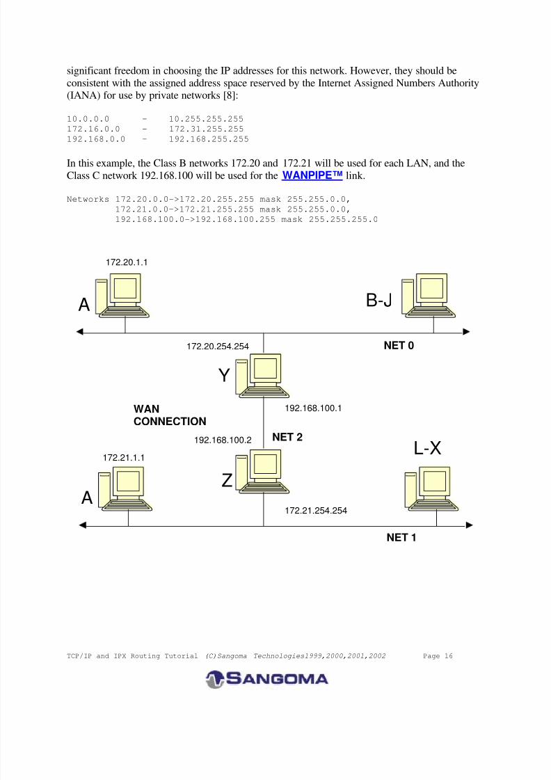
8/9/2019 TCPIP Routing Tutorial
http://slidepdf.com/reader/full/tcpip-routing-tutorial 16/22
TCP/IP and IPX Routing Tutorial (C)Sangoma Technologies1999,2000,2001,2002 Page 16
significant freedom in choosing the IP addresses for this network. However, they should be
consistent with the assigned address space reserved by the Internet Assigned Numbers Authority(IANA) for use by private networks [8]:
10.0.0.0 - 10.255.255.255
172.16.0.0 - 172.31.255.255
192.168.0.0 - 192.168.255.255
In this example, the Class B networks 172.20 and 172.21 will be used for each LAN, and the
Class C network 192.168.100 will be used for the WANPIPE™ link.
Networks 172.20.0.0->172.20.255.255 mask 255.255.0.0,
172.21.0.0->172.21.255.255 mask 255.255.0.0,
192.168.100.0->192.168.100.255 mask 255.255.255.0
172.20.1.1
NET 1
172.21.1.1
192.168.100.2
Y
A B-J
172.20.254.254
A
L-X
Z
192.168.100.1
172.21.254.254
NET 0
NET 2
WANCONNECTION
8/9/2019 TCPIP Routing Tutorial
http://slidepdf.com/reader/full/tcpip-routing-tutorial 17/22
TCP/IP and IPX Routing Tutorial (C)Sangoma Technologies1999,2000,2001,2002 Page 17
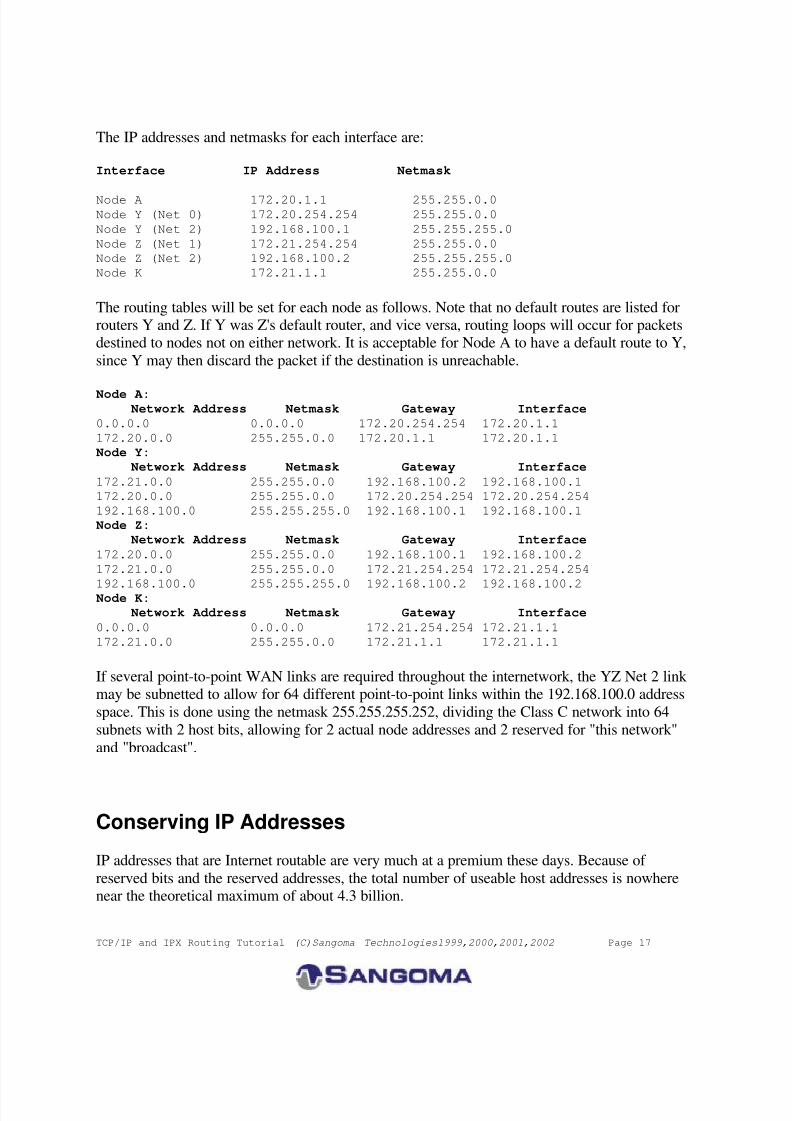
The IP addresses and netmasks for each interface are:
Interface IP Address Netmask
Node A 172.20.1.1 255.255.0.0Node Y (Net 0) 172.20.254.254 255.255.0.0
Node Y (Net 2) 192.168.100.1 255.255.255.0
Node Z (Net 1) 172.21.254.254 255.255.0.0
Node Z (Net 2) 192.168.100.2 255.255.255.0
Node K 172.21.1.1 255.255.0.0
The routing tables will be set for each node as follows. Note that no default routes are listed forrouters Y and Z. If Y was Z's default router, and vice versa, routing loops will occur for packetsdestined to nodes not on either network. It is acceptable for Node A to have a default route to Y,
since Y may then discard the packet if the destination is unreachable.
Node A: Network Address Netmask Gateway Interface
0.0.0.0 0.0.0.0 172.20.254.254 172.20.1.1
172.20.0.0 255.255.0.0 172.20.1.1 172.20.1.1
Node Y:
Network Address Netmask Gateway Interface
172.21.0.0 255.255.0.0 192.168.100.2 192.168.100.1
172.20.0.0 255.255.0.0 172.20.254.254 172.20.254.254
192.168.100.0 255.255.255.0 192.168.100.1 192.168.100.1
Node Z:
Network Address Netmask Gateway Interface
172.20.0.0 255.255.0.0 192.168.100.1 192.168.100.2
172.21.0.0 255.255.0.0 172.21.254.254 172.21.254.254
192.168.100.0 255.255.255.0 192.168.100.2 192.168.100.2 Node K:
Network Address Netmask Gateway Interface
0.0.0.0 0.0.0.0 172.21.254.254 172.21.1.1
172.21.0.0 255.255.0.0 172.21.1.1 172.21.1.1
If several point-to-point WAN links are required throughout the internetwork, the YZ Net 2 link may be subnetted to allow for 64 different point-to-point links within the 192.168.100.0 address
space. This is done using the netmask 255.255.255.252, dividing the Class C network into 64
subnets with 2 host bits, allowing for 2 actual node addresses and 2 reserved for "this network"
and "broadcast".
Conserving IP Addresses
IP addresses that are Internet routable are very much at a premium these days. Because of
reserved bits and the reserved addresses, the total number of useable host addresses is nowherenear the theoretical maximum of about 4.3 billion.
8/9/2019 TCPIP Routing Tutorial
http://slidepdf.com/reader/full/tcpip-routing-tutorial 18/22
TCP/IP and IPX Routing Tutorial (C)Sangoma Technologies1999,2000,2001,2002 Page 18
It is clear from the above examples that routing “by the book” can waste huge numbers of IP
addresses. Every subnetting of a Class C wastes a minimum of half the addresses due tosubnetting rules. If one is using a subnet simply to provide a 2-node network segment such as a
WAN link, all but two nodes of the subnet are wasted.
The more sophisticated routing platforms (usually Unix based) often include mechanisms thatcan conserve IP address space.
Private addresses
Consider a LAN connected to an Internet gateway via a Point-to-Point WAN link. Why notsimply use addresses for the WAN segment from the assigned address space reserved by the
Internet Assigned Numbers Authority (IANA) for use by private networks, such as, say,
192.168.x.y?
This will work quite well for all the nodes on the LAN, which presumably have valid public IP
addresses, but the machine acting as the WAN router itself will be invisible to the Internet. Anypacket transmitted from the router towards the Internet would normally carry the IP address of the interface used, in this case an IP address in the 192.168.x.y range. Because these are
recognized as private addresses, the routers in the Internet will simply drop these packets. So you
could ping any workstation on the LAN, but not the router itself.
Unnumbered links
Many Unix type platforms such as Linux or FreeBSD use interface names for internal routingrather than IP addresses. Thus for instance, a Linux server “knows” the difference between
201.33.15.1 assigned to eth0 and the same address assigned to wanpipe1_ppp. You can assign a
network address to eth0 and a default route to wanpipe1_ppp and the routing engine candiscriminate between them, even if they have the same address. So packets destined for the
network are correctly routed out of eth0 and packets destined for the wide world exit through
wanpipe1_ppp.
Note that this violates most routing rules in that two separate networks share a common address.
However, the violation is purely local and such an arrangement works perfectly well. Not a
single IP address is wasted, and packets from the router to the Internet have a perfectly routableIP address.
At the time of writing, the Windows environments use only IP addresses to identify interfaces,and so this technique is not an option.
NAT and Proxy servers
NAT (Network Address Translation) provides even greater IP savings, in that an entire network
can look to the Internet like one (very busy!) IP address. Packages such as IP Masquerade underLinux, monitor the traffic destined for the WAN and translate the addresses from those used on
the LAN to a single assigned public IP address. This is not much of a trick, the difficulty arises
8/9/2019 TCPIP Routing Tutorial
http://slidepdf.com/reader/full/tcpip-routing-tutorial 19/22
TCP/IP and IPX Routing Tutorial (C)Sangoma Technologies1999,2000,2001,2002 Page 19
in assigning packets coming in to the correct internal LAN host address. Some of the IP
protocols are easier to masquerade than others, protocols like ftp and UDP being notoriouslydifficult. Nonetheless, most packages work reliably for nearly all purposes.
The internal LAN will typically use addresses from the private address pool. This, coupled with
the fact that any NAT session must be initiated from inside the LAN, provides a simple but quiteeffective security system, making it difficult for a hacker to access any of the LAN hosts.
Proxy servers perform a similar NAT function but include additional security features.
IPX Routing
The following is a brief introduction to IPX routing in the context of a Novell environment. Formore information, consult Novell's IPX Router reference.
Because IPX is always dynamically routed, and the routing architecture works by "learning"network addressing automatically, there is usually no need to do anything special in the setup of
an IPX network in order to get routing to function. Thus this section is provided for
completeness only.
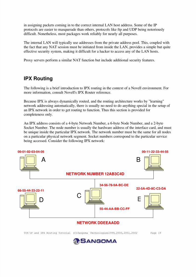
An IPX address consists of a 4-byte Network Number, a 6-byte Node Number, and a 2-byte
Socket Number. The node number is usually the hardware address of the interface card, and mustbe unique inside the particular IPX network. The network number must be the same for all nodes
on a particular physical network segment. Socket numbers correspond to the particular service
being accessed. Consider the following IPX network:
55-44-AA-BB-CC-FF
NETWORK DDEEAADD
NETWORK NUMBER 12AB3C4D
00-01-02-03-04-05
34-56-78-9A-BC-DE
00-11-22-33-44-55
22-5A-4D-8C-C3-DA
A B
C
66-55-44-33-22-11
D
8/9/2019 TCPIP Routing Tutorial
http://slidepdf.com/reader/full/tcpip-routing-tutorial 20/22
TCP/IP and IPX Routing Tutorial (C)Sangoma Technologies1999,2000,2001,2002 Page 20
Networks 12AB3C4D and DDEEAADD
Nodes A and D are Novell NetWare workstations, and Nodes B, C and E are Novell NetWare
Servers. Node C has two Ethernet cards and acts as an IPX router between the two networks.
The NetWare Servers broadcast routing information and service advertisements to all nodes onthe network segment using RIP/SAP or NLSP. Node C forwards this information to connected
networks, so that workstations are made aware of the addresses of all file and print servers
available, and servers are made aware of the routes to these other servers.
To address a service running on a server, each server has its own Internal Network Number,
which is placed in the network number field of the IPX header.
For example, suppose A wants to access the file server E whose internal network number is
5E1C0155. A would have been made aware of E's address through service advertisementsbroadcast by C. To learn how to reach E, it broadcasts a routing request. C receives this request
and returns its own hardware node number. A therefore addresses an IPX packet to E using E's
internal network number of 5E1C0155 and node number 22-5A-4D-8C-C3-DA. The Ethernetheader's destination address is Node C's node address of 34-56-78-9A-BC-DE. C then receives
this IPX packet and observes that the IPX packet header's destination address is not its own, so it
transmits the packet on network DDEEAADD knowing that E is on that network, using an
Ethernet header destination address of 22-5A-4D-8C-C3-DA.
See the WANPIPE™ operations manual for information on configuring WANPIPE™ f or usewith IPX.
Appendix: Restrictions in the use of class C subnetting
The rules for forming an IP address include the following:
"IP addresses are not permitted to have the value 0 or -1 for any of the <Host-number>,
<Network-number>, or <Subnet-number> fields (except in the special cases listed above
[relating to broadcast or network addresses]). This implies that each of these fields will
be at least two bits long." [RFC 1716, Almquist & Kastenholz, p.45]
If this rule must be adhered to, the netmask 255.255.255.128 cannot be used because only one bit
is reserved for the <Subnet-number>, and so it can only take on the value of 0 or -1 (being allone's). However, it was found that many TCP/IP implementations do not seem to enforce this
rule. This includes Microsoft Windows and SCO Unix. Novell NetWare Server's TCP/IPhowever does insist that the <Subnet-number> not be -1, but it can be 0.
8/9/2019 TCPIP Routing Tutorial
http://slidepdf.com/reader/full/tcpip-routing-tutorial 21/22
TCP/IP and IPX Routing Tutorial (C)Sangoma Technologies1999,2000,2001,2002 Page 21
This rule also implies that the use of the netmask 255.255.255.192, which creates four distinct
networks, only allows for the use of two. Writing this netmask in hex, it is FFFFFFC0which in binary is:
11111111 11111111 11111111 11000000.
\------------------------/ \/\----/<Network-number> | <Host-number>
|
+-- <Subnet-number>
At first, it appears that four subnet numbers are available:
00, 01, 10 and 11. However, since the rule says that it cannot be 0 or -1, only two subnetnumbers are available: 01 and 10.
From the example in section 4 of the Tutorial, with a class C network number of 210.20.30, thefollowing ranges are available for use:
Net# Address Range
---- -------------
01 210.20.30.65 to 210.20.30.126 --> VALID
10 210.20.30.129 to 210.20.30.190 --> VALID
The following ranges are wasted:
Net# Address Range
---- -------------
00 210.20.30.1 to 210.20.30.62 --> WASTED
11 210.20.30.193 to 210.20.30.254 --> WASTED
These do not include the network and broadcast addresses.
The example on Page 8 can be made to work using the same netmask of 255.255.255.192 if theTCP/IP implementation allows the use of the 0 subnet number. In this case, the only change is to
use Net#2 as opposed to Net#3 for the WAN connection. Node C (WAN) can have IP address
210.20.30.130, and the gateway node can have IP address 210.20.30.190.
If the 0 subnet number cannot be used, the netmask will have to change to FFFFFFE0, or255.255.255.224, to give 3 subnet bits. The subnet numbers in binary are then: 000 001 010 011
100 101 110 111. The numbers 000 and 111 are illegal, leaving 6 networks. The valid IP
addresses would then be:
Net# Address Range
---- -------------
001 210.20.30.33 to 210.20.30.62
010 210.20.30.65 to 210.20.30.94
011 210.20.30.97 to 210.20.30.126
100 210.20.30.129 to 210.20.30.158
101 210.20.30.161 to 210.20.30.190
110 210.20.30.193 to 210.20.30.222
8/9/2019 TCPIP Routing Tutorial
http://slidepdf.com/reader/full/tcpip-routing-tutorial 22/22
TCP/IP and IPX Routing Tutorial (C)Sangoma Technologies1999,2000,2001,2002 Page 22
These do not include the network and broadcast addresses.
To implement this change in the example, map the IP addresses in each of the three networks to
those in the table above. This will leave three networks unused. For example:
Node From To
---- ---- --
A 210.20.30.1 210.20.30.33 (Net# 001)
B 210.20.30.2 210.20.30.34 (Net# 001)
C (AB) 210.20.30.10 210.20.30.40 (Net# 001)
C (DE) 210.20.30.70 210.20.30.65 (Net# 010)
C (WAN) 210.20.30.200 210.20.30.97 (Net# 011)
D 210.20.30.81 210.20.30.66 (Net# 010)
E 210.20.30.82 210.20.30.67 (Net# 010)
G 210.20.30.254 210.20.30.126 (Net# 011)
Depending on the operating systems or routers used, the netmask 255.255.255.128 may or may
not be acceptable. If at all possible, the 0 and -1 subnet numbers should be avoided. By following
this rule, it should be possible to interchange router equipment within the network withouthaving to change the addressing scheme in order to satisfy rules that may or may not be
enforced.
References
1. T. Socolofsky, C. Kale, "A TCP/IP Tutorial", RFC 1180, 01/15/1991.2. J. Reynolds, J.Postel, "ASSIGNED NUMBERS", RFC 1700, 10/20/1994.
3. J. Postel, "Internet Protocol", RFC 791, 09/01/1981.
4. V. Fuller, T. Li, J. Yu, K. Varadhan, "Classless Inter-Domain Routing (CIDR): anAddress Assignment and Aggregation Strategy", RFC 1519, 09/24/1993.
5. E. Gerich, "Guidelines for Management of IP Address Space", RFC 1466, 05/26/1993.
6. "Novell NetWare v3.11 TCP/IP Transport Supervisor's Guide", Novell, Inc., 03/25/1991.7. route(ADMN) and ifconfig(ADMN) man pages, SCO Unix SVR3.2 V4.2.
8. Y. Rekhter, R. Moskowitz, D.Karrenberg, G. de Groot, "Address Allocation for Private
Internets", RFC 1597, 03/17/1994.9. "Microsoft Windows NT Server TCP/IP", TCPIP.HLP, Microsoft Corporation,
09/04/1994. Available on distribution CD in \support\books, or in the Windows NT
system32 directory.
10. “Microsoft Windows 95 Resource Kit", WIN95RK.HLP, Microsoft Corporation,06/11/1995. Available in the \windows\help directory.
11. P. Almquist, F. Kastenholz, "Towards Requirements for IP Routers", RFC 1716,
11/04/1994.12. T. Bradley, C. Brown, A. Malis, "Multiprotocol Interconnect over frame Relay", RFC
1490, 07/26/1993.


![[French Fr Internet Tutorial Cours TCPIP] tcp-ip protocoles de l'internet](https://img.pdfslide.us/doc/110x75/577dae581a28ab223f9059a1/french-fr-internet-tutorial-cours-tcpip-tcp-ip-protocoles-de-linternet.jpg)