Embed Size (px)
Citation preview
1
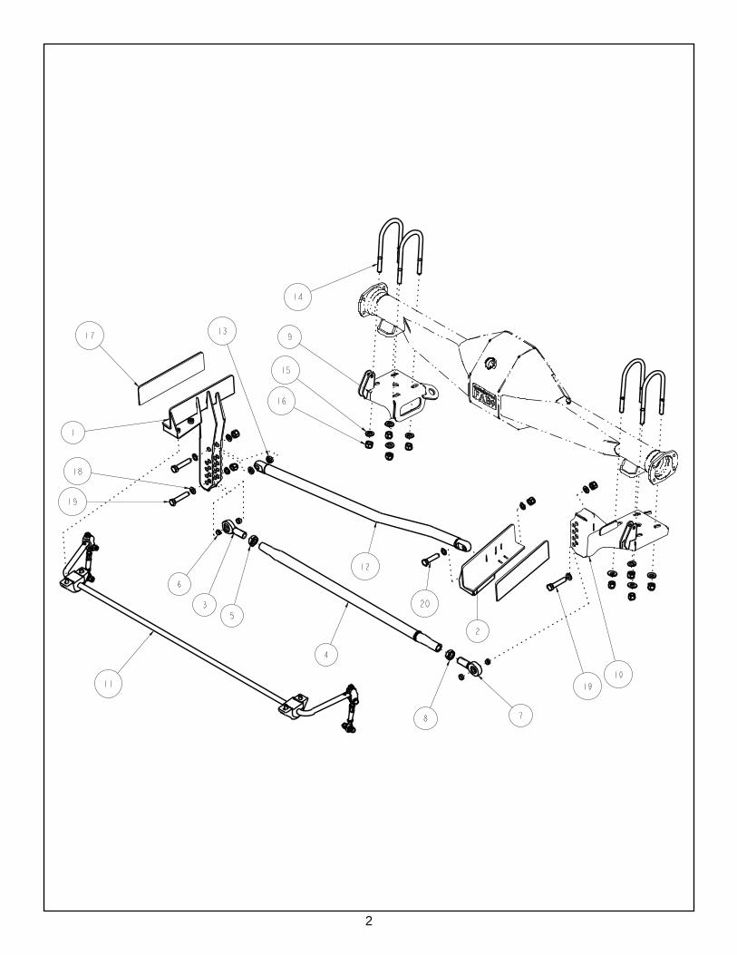
TCP PHL-M10Panhard Bar System
for 1964-73 Mustang and 1967-73 Cougar
Description: Weld-in panhard bar system for use with leaf-spring suspensions. Lateral suspension locater device, adjustable for various ride heights and roll center height.Applications: Mustang ‘64-73, Cougar ‘67-73Fitment: Does not fi t with factory staggered shocks. Both shocks must mount forward of the rearend housing.
INSTALLATION GUIDE
READ ALL INSTRUCTIONS COMPLETELY AND THOROUGHLY UNDERSTAND THEM BEFORE DOING ANYTHING. CALL TOTAL CONTROL PRODUCTS TECH SUPPORT (916) 388-0288 IF YOU NEED ASSISTANCE.
2
3
(OPTIONAL PART)
(OPTIONAL PART)
(OPTIONAL PART)
(OPTIONAL PARTS - 4 INCLUDED WITH PANHARD BAR)
4
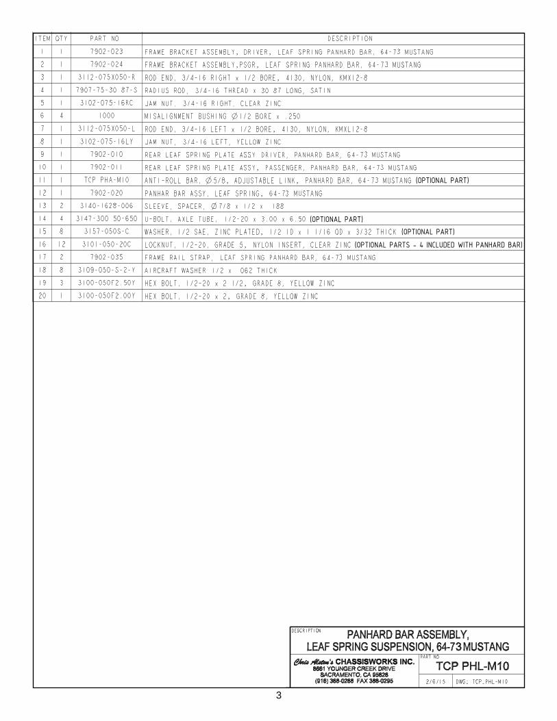
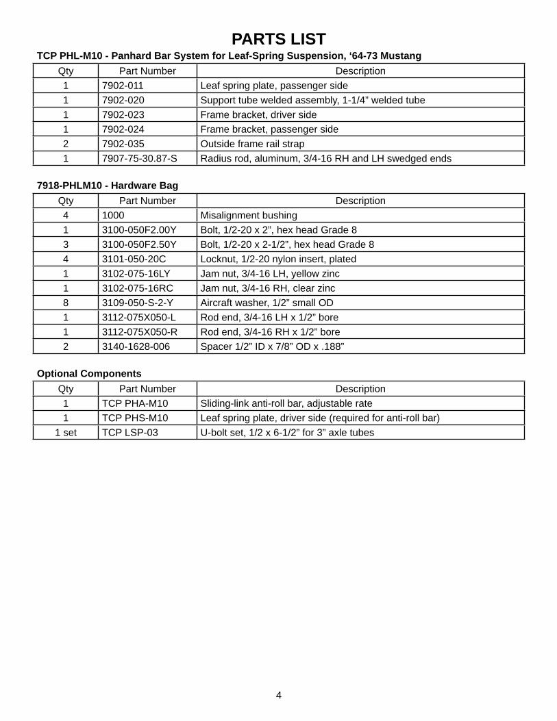
PARTS LISTTCP PHL-M10 - Panhard Bar System for Leaf-Spring Suspension, ‘64-73 Mustang
Qty Part Number Description1 7902-011 Leaf spring plate, passenger side1 7902-020 Support tube welded assembly, 1-1/4” welded tube1 7902-023 Frame bracket, driver side1 7902-024 Frame bracket, passenger side2 7902-035 Outside frame rail strap1 7907-75-30.87-S Radius rod, aluminum, 3/4-16 RH and LH swedged ends
7918-PHLM10 - Hardware BagQty Part Number Description4 1000 Misalignment bushing1 3100-050F2.00Y Bolt, 1/2-20 x 2”, hex head Grade 83 3100-050F2.50Y Bolt, 1/2-20 x 2-1/2”, hex head Grade 84 3101-050-20C Locknut, 1/2-20 nylon insert, plated1 3102-075-16LY Jam nut, 3/4-16 LH, yellow zinc1 3102-075-16RC Jam nut, 3/4-16 RH, clear zinc8 3109-050-S-2-Y Aircraft washer, 1/2” small OD1 3112-075X050-L Rod end, 3/4-16 LH x 1/2” bore1 3112-075X050-R Rod end, 3/4-16 RH x 1/2” bore2 3140-1628-006 Spacer 1/2” ID x 7/8” OD x .188”
Optional ComponentsQty Part Number Description1 TCP PHA-M10 Sliding-link anti-roll bar, adjustable rate1 TCP PHS-M10 Leaf spring plate, driver side (required for anti-roll bar)
1 set TCP LSP-03 U-bolt set, 1/2 x 6-1/2” for 3” axle tubes
5
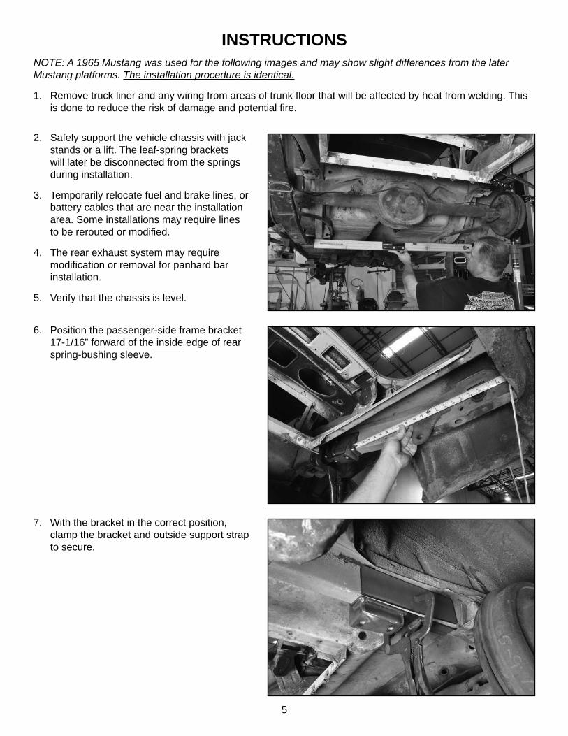
INSTRUCTIONSNOTE: A 1965 Mustang was used for the following images and may show slight differences from the later Mustang platforms. The installation procedure is identical.
1. Remove truck liner and any wiring from areas of trunk fl oor that will be affected by heat from welding. This is done to reduce the risk of damage and potential fi re.
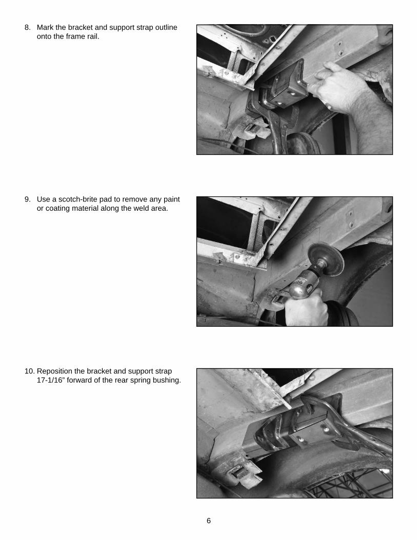
6. Position the passenger-side frame bracket 17-1/16” forward of the inside edge of rear spring-bushing sleeve.
2. Safely support the vehicle chassis with jack stands or a lift. The leaf-spring brackets will later be disconnected from the springs during installation.
3. Temporarily relocate fuel and brake lines, or battery cables that are near the installation area. Some installations may require lines to be rerouted or modifi ed.
4. The rear exhaust system may require modifi cation or removal for panhard bar installation.
5. Verify that the chassis is level.
7. With the bracket in the correct position, clamp the bracket and outside support strap to secure.
6
9. Use a scotch-brite pad to remove any paint or coating material along the weld area.
10. Reposition the bracket and support strap 17-1/16” forward of the rear spring bushing.
8. Mark the bracket and support strap outline onto the frame rail.
7
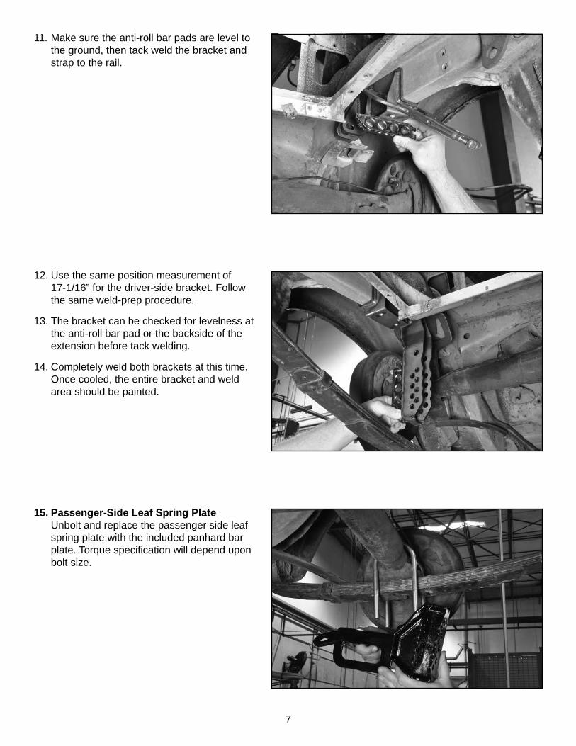
15. Passenger-Side Leaf Spring PlateUnbolt and replace the passenger side leaf spring plate with the included panhard bar plate. Torque specifi cation will depend upon bolt size.
11. Make sure the anti-roll bar pads are level to the ground, then tack weld the bracket and strap to the rail.
12. Use the same position measurement of 17-1/16” for the driver-side bracket. Follow the same weld-prep procedure.
13. The bracket can be checked for levelness at the anti-roll bar pad or the backside of the extension before tack welding.
14. Completely weld both brackets at this time. Once cooled, the entire bracket and weld area should be painted.
8
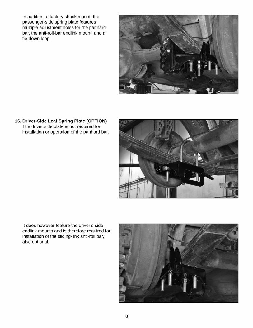
16. Driver-Side Leaf Spring Plate (OPTION)The driver side plate is not required for installation or operation of the panhard bar.
In addition to factory shock mount, the passenger-side spring plate features multiple adjustment holes for the panhard bar, the anti-roll-bar endlink mount, and a tie-down loop.
It does however feature the driver’s side endlink mounts and is therefore required for installation of the sliding-link anti-roll bar, also optional.
9
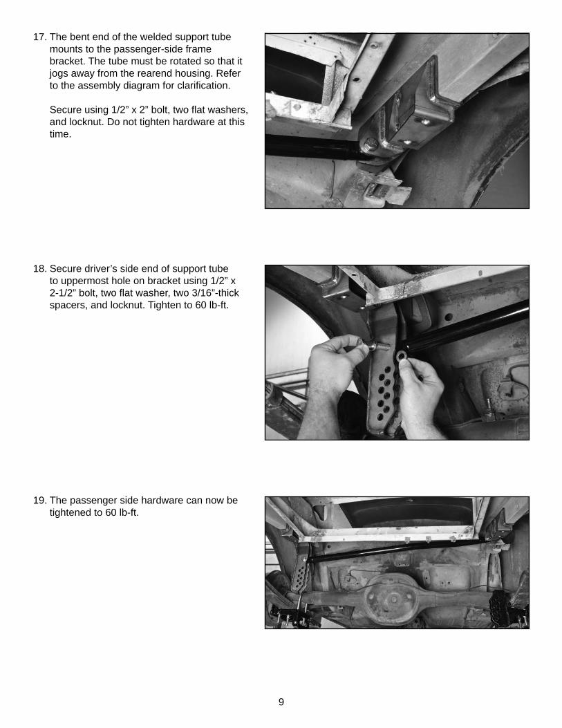
19. The passenger side hardware can now be tightened to 60 lb-ft.
18. Secure driver’s side end of support tube to uppermost hole on bracket using 1/2” x 2-1/2” bolt, two fl at washer, two 3/16”-thick spacers, and locknut. Tighten to 60 lb-ft.
17. The bent end of the welded support tube mounts to the passenger-side frame bracket. The tube must be rotated so that it jogs away from the rearend housing. Refer to the assembly diagram for clarifi cation.
Secure using 1/2” x 2” bolt, two fl at washers, and locknut. Do not tighten hardware at this time.
10
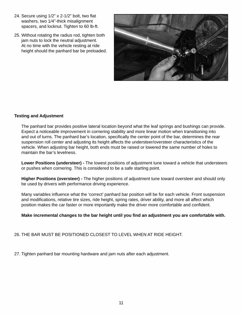
23. The opposite end of the panhard bar must be installed at the hole on the axle bracket that positions the bar closest to level. Rotating the radius rod will lengthen or shorten the bar as needed. Do not rotate the free rod end with the radius rod.
There must be at least 3/4” thread engagement between the rod end and radius rod and no more than 9 threads exposed above the jam nut.
The following steps should be performed with the weight of the vehicle on the suspension; either on the ground or with two jack stands placed along the axle tubes. The suspension should be resting at ride height.
22. The assembled panhard bar is initially positioned at the bottom hole of the chassis bracket. The bar may be raised after test driving the vehicle.
Secure using 1/2” x 2-1/2” bolt, two fl at washers, two 1/4”-thick misalignment spacers, and locknut. Tighten to 60 lb-ft.
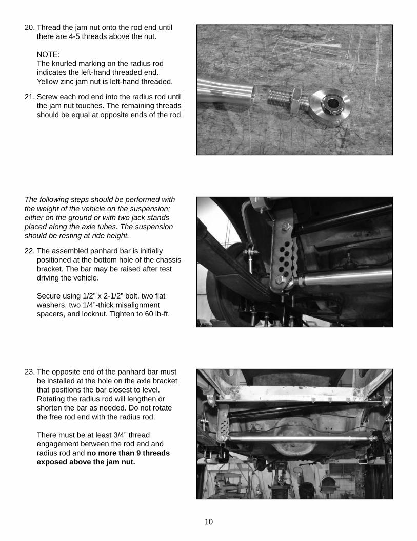
20. Thread the jam nut onto the rod end until there are 4-5 threads above the nut.
NOTE:The knurled marking on the radius rod indicates the left-hand threaded end.Yellow zinc jam nut is left-hand threaded.
21. Screw each rod end into the radius rod until the jam nut touches. The remaining threads should be equal at opposite ends of the rod.
11
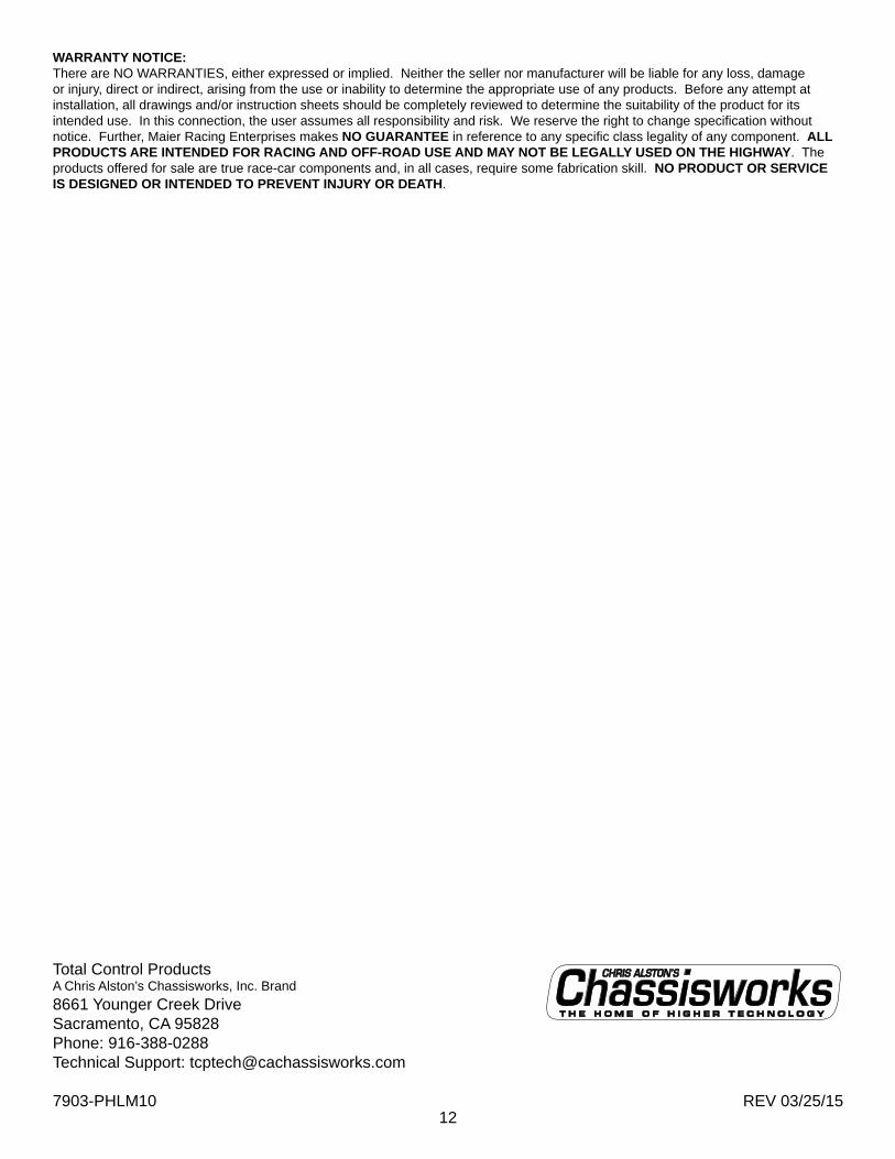
24. Secure using 1/2” x 2-1/2” bolt, two fl at washers, two 1/4”-thick misalignment spacers, and locknut. Tighten to 60 lb-ft.
25. Without rotating the radius rod, tighten both jam nuts to lock the neutral adjustment. At no time with the vehicle resting at ride height should the panhard bar be preloaded.
Testing and Adjustment
The panhard bar provides positive lateral location beyond what the leaf springs and bushings can provide. Expect a noticeable improvement in cornering stability and more linear motion when transitioning into and out of turns. The panhard bar’s location, specifi cally the center point of the bar, determines the rear suspension roll center and adjusting its height affects the understeer/oversteer characteristics of the vehicle. When adjusting bar height, both ends must be raised or lowered the same number of holes to maintain the bar’s levelness.
Lower Positions (understeer) - The lowest positions of adjustment tune toward a vehicle that understeers or pushes when cornering. This is considered to be a safe starting point.
Higher Positions (oversteer) - The higher positions of adjustment tune toward oversteer and should only be used by drivers with performance driving experience.
Many variables infl uence what the ‘correct’ panhard bar position will be for each vehicle. Front suspension and modifi cations, relative tire sizes, ride height, spring rates, driver ability, and more all affect which position makes the car faster or more importantly make the driver more comfortable and confi dent.
Make incremental changes to the bar height until you fi nd an adjustment you are comfortable with.
26. THE BAR MUST BE POSITIONED CLOSEST TO LEVEL WHEN AT RIDE HEIGHT.
27. Tighten panhard bar mounting hardware and jam nuts after each adjustment.
12REV 03/25/15
WARRANTY NOTICE:There are NO WARRANTIES, either expressed or implied. Neither the seller nor manufacturer will be liable for any loss, damage or injury, direct or indirect, arising from the use or inability to determine the appropriate use of any products. Before any attempt at installation, all drawings and/or instruction sheets should be completely reviewed to determine the suitability of the product for its intended use. In this connection, the user assumes all responsibility and risk. We reserve the right to change specifi cation without notice. Further, Maier Racing Enterprises makes NO GUARANTEE in reference to any specifi c class legality of any component. ALL PRODUCTS ARE INTENDED FOR RACING AND OFF-ROAD USE AND MAY NOT BE LEGALLY USED ON THE HIGHWAY. The products offered for sale are true race-car components and, in all cases, require some fabrication skill. NO PRODUCT OR SERVICE IS DESIGNED OR INTENDED TO PREVENT INJURY OR DEATH.
Total Control ProductsA Chris Alston’s Chassisworks, Inc. Brand8661 Younger Creek DriveSacramento, CA 95828Phone: 916-388-0288Technical Support: [email protected]
7903-PHLM10