Embed Size (px)
DESCRIPTION
587
Citation preview
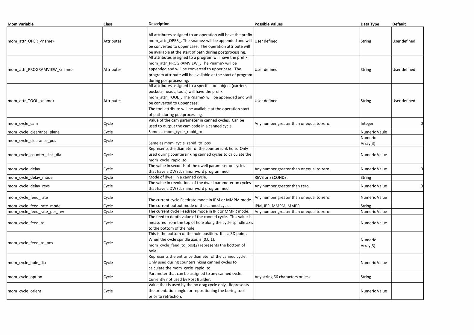
Mom Variable Class Description Possible Values Data Type Default
mom_attr_OPER_<name> Attributes
All attributes assigned to an operation will have the prefix
mom_attr_OPER_. The <name> will be appended and will
be converted to upper case. The operation attribute will
be available at the start of path during postprocessing.
User defined String User defined
mom_attr_PROGRAMVIEW_<name> Attributes
All attributes assigned to a program will have the prefix
mom_attr_PROGRAMVIEW_. The <name> will be
appended and will be converted to upper case. The
program attribute will be available at the start of program
during postprocessing.
User defined String User defined
mom_attr_TOOL_<name> Attributes
All attributes assigned to a specific tool object (carriers,
pockets, heads, tools) will have the prefix
mom_attr_TOOL_. The <name> will be appended and will
be converted to upper case.
The tool attribute will be available at the operation start
of path during postprocessing.
User defined String User defined
mom_cycle_cam CycleValue of the cam parameter in canned cycles. Can be
used to output the cam code in a canned cycle.Any number greater than or equal to zero. Integer 0
mom_cycle_clearance_plane Cycle Same as mom_cycle_rapid_to Numeric Vaule
mom_cycle_clearance_pos CycleSame as mom_cycle_rapid_to_pos
Numeric
Array(3)
mom_cycle_counter_sink_dia Cycle
Represents the diameter of the countersunk hole. Only
used during countersinking canned cycles to calculate the
mom_cycle_rapid_to.Numeric Value
mom_cycle_delay CycleThe value in seconds of the dwell parameter on cycles
that have a DWELL minor word programmed. Any number greater than or equal to zero. Numeric Value 0
mom_cycle_delay_mode Cycle Mode of dwell in a canned cycle. REVS or SECONDS. String
mom_cycle_delay_revs CycleThe value in revolutions of the dwell parameter on cycles
that have a DWELL minor word programmed. Any number greater than zero. Numeric Value 0
mom_cycle_feed_rate CycleThe current cycle Feedrate mode in IPM or MMPM mode.
Any number greater than or equal to zero. Numeric Value
mom_cycle_feed_rate_mode Cycle The current output mode of the canned cycle. IPM, IPR, MMPM, MMPR String
mom_cycle_feed_rate_per_rev Cycle The current cycle Feedrate mode in IPR or MMPR mode. Any number greater than or equal to zero. Numeric Value
mom_cycle_feed_to Cycle
The feed to depth value of the canned cycle. This value is
measured from the top of hole along the cycle spindle axis
to the bottom of the hole.Numeric Value
mom_cycle_feed_to_pos Cycle
This is the bottom of the hole position. It is a 3D point.
When the cycle spindle axis is (0,0,1),
mom_cycle_feed_to_pos(2) represents the bottom of
hole.
Numeric
Array(3)
mom_cycle_hole_dia Cycle
Represents the entrance diameter of the canned cycle.
Only used during countersinking canned cycles to
calculate the mom_cycle_rapid_to..Numeric Value
mom_cycle_option CycleParameter that can be assigned to any canned cycle.
Currently not used by Post Builder.Any string 66 characters or less. String
mom_cycle_orient Cycle
Value that is used by the no drag cycle only. Represents
the orientation angle for repositioning the boring tool
prior to retraction.Numeric Value
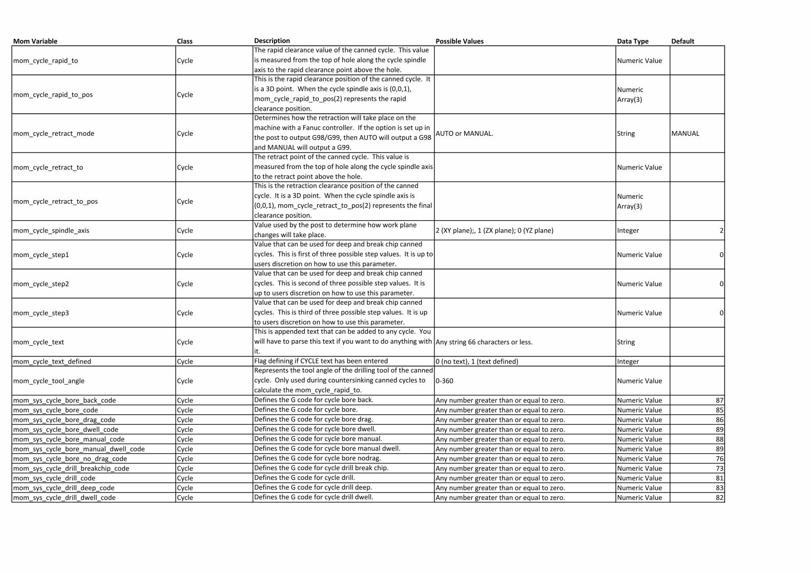
Mom Variable Class Description Possible Values Data Type Default
mom_cycle_rapid_to Cycle
The rapid clearance value of the canned cycle. This value
is measured from the top of hole along the cycle spindle
axis to the rapid clearance point above the hole.Numeric Value
mom_cycle_rapid_to_pos Cycle
This is the rapid clearance position of the canned cycle. It
is a 3D point. When the cycle spindle axis is (0,0,1),
mom_cycle_rapid_to_pos(2) represents the rapid
clearance position.
Numeric
Array(3)
mom_cycle_retract_mode Cycle
Determines how the retraction will take place on the
machine with a Fanuc controller. If the option is set up in
the post to output G98/G99, then AUTO will output a G98
and MANUAL will output a G99.
AUTO or MANUAL. String MANUAL
mom_cycle_retract_to Cycle
The retract point of the canned cycle. This value is
measured from the top of hole along the cycle spindle axis
to the retract point above the hole.Numeric Value
mom_cycle_retract_to_pos Cycle
This is the retraction clearance position of the canned
cycle. It is a 3D point. When the cycle spindle axis is
(0,0,1), mom_cycle_retract_to_pos(2) represents the final
clearance position.
Numeric
Array(3)
mom_cycle_spindle_axis CycleValue used by the post to determine how work plane
changes will take place. 2 (XY plane);, 1 (ZX plane); 0 (YZ plane) Integer 2
mom_cycle_step1 Cycle
Value that can be used for deep and break chip canned
cycles. This is first of three possible step values. It is up to
users discretion on how to use this parameter.Numeric Value 0
mom_cycle_step2 Cycle
Value that can be used for deep and break chip canned
cycles. This is second of three possible step values. It is
up to users discretion on how to use this parameter.Numeric Value 0
mom_cycle_step3 Cycle
Value that can be used for deep and break chip canned
cycles. This is third of three possible step values. It is up
to users discretion on how to use this parameter.Numeric Value 0
mom_cycle_text Cycle
This is appended text that can be added to any cycle. You
will have to parse this text if you want to do anything with
it.Any string 66 characters or less. String
mom_cycle_text_defined Cycle Flag defining if CYCLE text has been entered 0 (no text), 1 (text defined) Integer
mom_cycle_tool_angle Cycle
Represents the tool angle of the drilling tool of the canned
cycle. Only used during countersinking canned cycles to
calculate the mom_cycle_rapid_to.0-360 Numeric Value
mom_sys_cycle_bore_back_code Cycle Defines the G code for cycle bore back. Any number greater than or equal to zero. Numeric Value 87
mom_sys_cycle_bore_code Cycle Defines the G code for cycle bore. Any number greater than or equal to zero. Numeric Value 85
mom_sys_cycle_bore_drag_code Cycle Defines the G code for cycle bore drag. Any number greater than or equal to zero. Numeric Value 86
mom_sys_cycle_bore_dwell_code Cycle Defines the G code for cycle bore dwell. Any number greater than or equal to zero. Numeric Value 89
mom_sys_cycle_bore_manual_code Cycle Defines the G code for cycle bore manual. Any number greater than or equal to zero. Numeric Value 88
mom_sys_cycle_bore_manual_dwell_code Cycle Defines the G code for cycle bore manual dwell. Any number greater than or equal to zero. Numeric Value 89
mom_sys_cycle_bore_no_drag_code Cycle Defines the G code for cycle bore nodrag. Any number greater than or equal to zero. Numeric Value 76
mom_sys_cycle_drill_breakchip_code Cycle Defines the G code for cycle drill break chip. Any number greater than or equal to zero. Numeric Value 73
mom_sys_cycle_drill_code Cycle Defines the G code for cycle drill. Any number greater than or equal to zero. Numeric Value 81
mom_sys_cycle_drill_deep_code Cycle Defines the G code for cycle drill deep. Any number greater than or equal to zero. Numeric Value 83
mom_sys_cycle_drill_dwell_code Cycle Defines the G code for cycle drill dwell. Any number greater than or equal to zero. Numeric Value 82
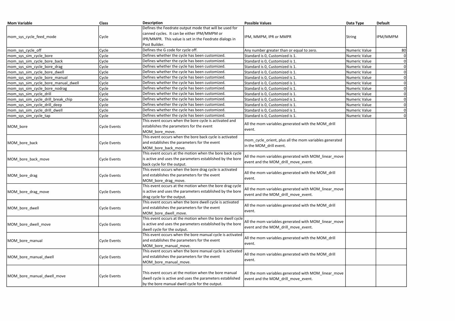
Mom Variable Class Description Possible Values Data Type Default
mom_sys_cycle_feed_mode Cycle
Defines the Feedrate output mode that will be used for
canned cycles. It can be either IPM/MMPM or
IPR/MMPR. This value is set in the Feedrate dialogs in
Post Builder.
IPM, MMPM, IPR or MMPR String IPM/MMPM
mom_sys_cycle_off Cycle Defines the G code for cycle off. Any number greater than or equal to zero. Numeric Value 80
mom_sys_sim_cycle_bore Cycle Defines whether the cycle has been customized. Standard is 0, Customized is 1. Numeric Value 0
mom_sys_sim_cycle_bore_back Cycle Defines whether the cycle has been customized. Standard is 0, Customized is 1. Numeric Value 0
mom_sys_sim_cycle_bore_drag Cycle Defines whether the cycle has been customized. Standard is 0, Customized is 1. Numeric Value 0
mom_sys_sim_cycle_bore_dwell Cycle Defines whether the cycle has been customized. Standard is 0, Customized is 1. Numeric Value 0
mom_sys_sim_cycle_bore_manual Cycle Defines whether the cycle has been customized. Standard is 0, Customized is 1. Numeric Value 0
mom_sys_sim_cycle_bore_manual_dwell Cycle Defines whether the cycle has been customized. Standard is 0, Customized is 1. Numeric Value 0
mom_sys_sim_cycle_bore_nodrag Cycle Defines whether the cycle has been customized. Standard is 0, Customized is 1. Numeric Value 0
mom_sys_sim_cycle_drill Cycle Defines whether the cycle has been customized. Standard is 0, Customized is 1. Numeric Value 0
mom_sys_sim_cycle_drill_break_chip Cycle Defines whether the cycle has been customized. Standard is 0, Customized is 1. Numeric Value 0
mom_sys_sim_cycle_drill_deep Cycle Defines whether the cycle has been customized. Standard is 0, Customized is 1. Numeric Value 0
mom_sys_sim_cycle_drill_dwell Cycle Defines whether the cycle has been customized. Standard is 0, Customized is 1. Numeric Value 0
mom_sys_sim_cycle_tap Cycle Defines whether the cycle has been customized. Standard is 0, Customized is 1. Numeric Value 0
MOM_bore Cycle Events
This event occurs when the bore cycle is activated and
establishes the parameters for the event
MOM_bore_move.
All the mom variables generated with the MOM_drill
event.
MOM_bore_back Cycle Events
This event occurs when the bore back cycle is activated
and establishes the parameters for the event
MOM_bore_back_move.
mom_cycle_orient, plus all the mom variables generated
in the MOM_drill event.
MOM_bore_back_move Cycle Events
This event occurs at the motion when the bore back cycle
is active and uses the parameters established by the bore
back cycle for the output.
All the mom variables generated with MOM_linear_move
event and the MOM_drill_move_event.
MOM_bore_drag Cycle Events
This event occurs when the bore drag cycle is activated
and establishes the parameters for the event
MOM_bore_drag_move.
All the mom variables generated with the MOM_drill
event.
MOM_bore_drag_move Cycle Events
This event occurs at the motion when the bore drag cycle
is active and uses the parameters established by the bore
drag cycle for the output.
All the mom variables generated with MOM_linear_move
event and the MOM_drill_move_event.
MOM_bore_dwell Cycle Events
This event occurs when the bore dwell cycle is activated
and establishes the parameters for the event
MOM_bore_dwell_move.
All the mom variables generated with the MOM_drill
event.
MOM_bore_dwell_move Cycle Events
This event occurs at the motion when the bore dwell cycle
is active and uses the parameters established by the bore
dwell cycle for the output.
All the mom variables generated with MOM_linear_move
event and the MOM_drill_move_event.
MOM_bore_manual Cycle Events
This event occurs when the bore manual cycle is activated
and establishes the parameters for the event
MOM_bore_manual_move.
All the mom variables generated with the MOM_drill
event.
MOM_bore_manual_dwell Cycle Events
This event occurs when the bore manual cycle is activated
and establishes the parameters for the event
MOM_bore_manual_move.
All the mom variables generated with the MOM_drill
event.
MOM_bore_manual_dwell_move Cycle EventsThis event occurs at the motion when the bore manual
dwell cycle is active and uses the parameters established
by the bore manual dwell cycle for the output.
All the mom variables generated with MOM_linear_move
event and the MOM_drill_move_event.
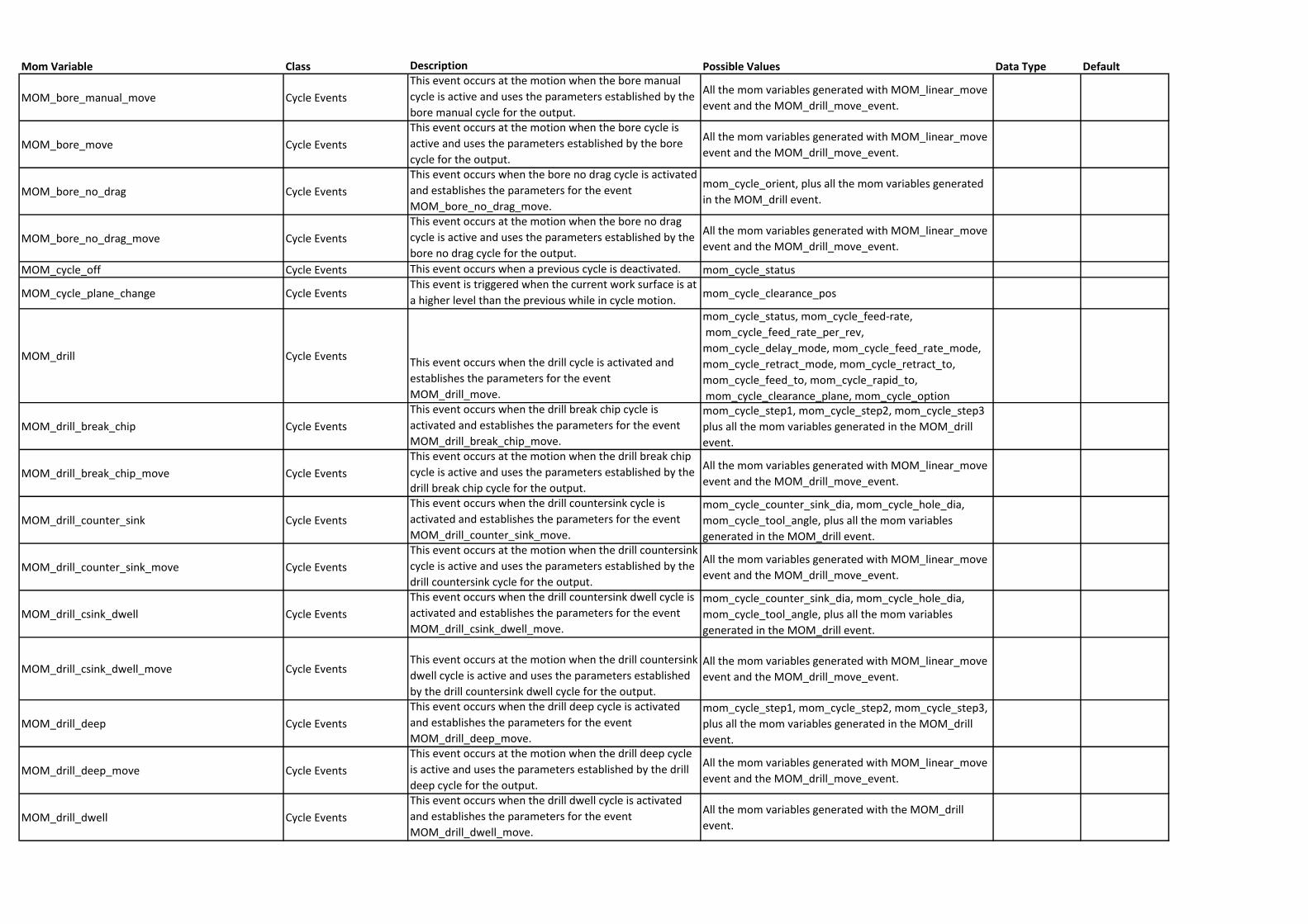
Mom Variable Class Description Possible Values Data Type Default
MOM_bore_manual_move Cycle Events
This event occurs at the motion when the bore manual
cycle is active and uses the parameters established by the
bore manual cycle for the output.
All the mom variables generated with MOM_linear_move
event and the MOM_drill_move_event.
MOM_bore_move Cycle Events
This event occurs at the motion when the bore cycle is
active and uses the parameters established by the bore
cycle for the output.
All the mom variables generated with MOM_linear_move
event and the MOM_drill_move_event.
MOM_bore_no_drag Cycle Events
This event occurs when the bore no drag cycle is activated
and establishes the parameters for the event
MOM_bore_no_drag_move.
mom_cycle_orient, plus all the mom variables generated
in the MOM_drill event.
MOM_bore_no_drag_move Cycle Events
This event occurs at the motion when the bore no drag
cycle is active and uses the parameters established by the
bore no drag cycle for the output.
All the mom variables generated with MOM_linear_move
event and the MOM_drill_move_event.
MOM_cycle_off Cycle Events This event occurs when a previous cycle is deactivated. mom_cycle_status
MOM_cycle_plane_change Cycle EventsThis event is triggered when the current work surface is at
a higher level than the previous while in cycle motion.mom_cycle_clearance_pos
MOM_drill Cycle EventsThis event occurs when the drill cycle is activated and
establishes the parameters for the event
MOM_drill_move.
mom_cycle_status, mom_cycle_feed-rate,
mom_cycle_feed_rate_per_rev,
mom_cycle_delay_mode, mom_cycle_feed_rate_mode,
mom_cycle_retract_mode, mom_cycle_retract_to,
mom_cycle_feed_to, mom_cycle_rapid_to,
mom_cycle_clearance_plane, mom_cycle_option
MOM_drill_break_chip Cycle Events
This event occurs when the drill break chip cycle is
activated and establishes the parameters for the event
MOM_drill_break_chip_move.
mom_cycle_step1, mom_cycle_step2, mom_cycle_step3
plus all the mom variables generated in the MOM_drill
event.
MOM_drill_break_chip_move Cycle Events
This event occurs at the motion when the drill break chip
cycle is active and uses the parameters established by the
drill break chip cycle for the output.
All the mom variables generated with MOM_linear_move
event and the MOM_drill_move_event.
MOM_drill_counter_sink Cycle Events
This event occurs when the drill countersink cycle is
activated and establishes the parameters for the event
MOM_drill_counter_sink_move.
mom_cycle_counter_sink_dia, mom_cycle_hole_dia,
mom_cycle_tool_angle, plus all the mom variables
generated in the MOM_drill event.
MOM_drill_counter_sink_move Cycle Events
This event occurs at the motion when the drill countersink
cycle is active and uses the parameters established by the
drill countersink cycle for the output.
All the mom variables generated with MOM_linear_move
event and the MOM_drill_move_event.
MOM_drill_csink_dwell Cycle Events
This event occurs when the drill countersink dwell cycle is
activated and establishes the parameters for the event
MOM_drill_csink_dwell_move.
mom_cycle_counter_sink_dia, mom_cycle_hole_dia,
mom_cycle_tool_angle, plus all the mom variables
generated in the MOM_drill event.
MOM_drill_csink_dwell_move Cycle EventsThis event occurs at the motion when the drill countersink
dwell cycle is active and uses the parameters established
by the drill countersink dwell cycle for the output.
All the mom variables generated with MOM_linear_move
event and the MOM_drill_move_event.
MOM_drill_deep Cycle Events
This event occurs when the drill deep cycle is activated
and establishes the parameters for the event
MOM_drill_deep_move.
mom_cycle_step1, mom_cycle_step2, mom_cycle_step3,
plus all the mom variables generated in the MOM_drill
event.
MOM_drill_deep_move Cycle Events
This event occurs at the motion when the drill deep cycle
is active and uses the parameters established by the drill
deep cycle for the output.
All the mom variables generated with MOM_linear_move
event and the MOM_drill_move_event.
MOM_drill_dwell Cycle Events
This event occurs when the drill dwell cycle is activated
and establishes the parameters for the event
MOM_drill_dwell_move.
All the mom variables generated with the MOM_drill
event.
Mom Variable Class Description Possible Values Data Type Default
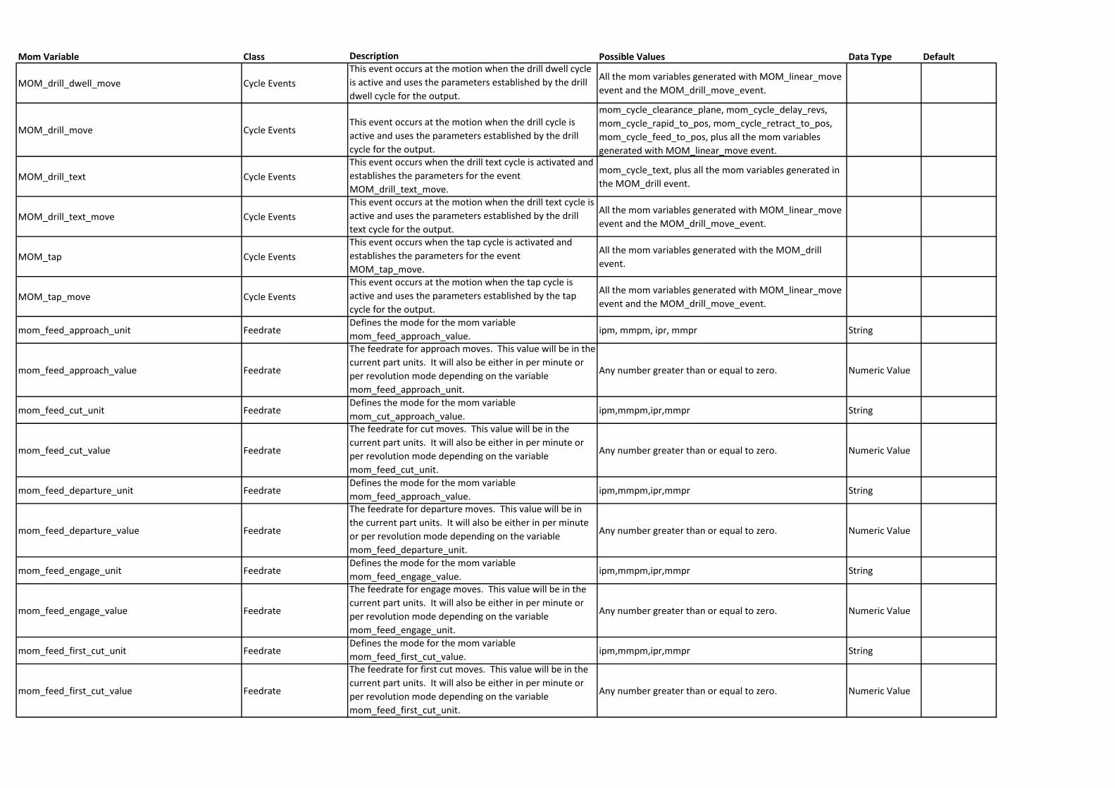
MOM_drill_dwell_move Cycle Events
This event occurs at the motion when the drill dwell cycle
is active and uses the parameters established by the drill
dwell cycle for the output.
All the mom variables generated with MOM_linear_move
event and the MOM_drill_move_event.
MOM_drill_move Cycle EventsThis event occurs at the motion when the drill cycle is
active and uses the parameters established by the drill
cycle for the output.
mom_cycle_clearance_plane, mom_cycle_delay_revs,
mom_cycle_rapid_to_pos, mom_cycle_retract_to_pos,
mom_cycle_feed_to_pos, plus all the mom variables
generated with MOM_linear_move event.
MOM_drill_text Cycle Events
This event occurs when the drill text cycle is activated and
establishes the parameters for the event
MOM_drill_text_move.
mom_cycle_text, plus all the mom variables generated in
the MOM_drill event.
MOM_drill_text_move Cycle Events
This event occurs at the motion when the drill text cycle is
active and uses the parameters established by the drill
text cycle for the output.
All the mom variables generated with MOM_linear_move
event and the MOM_drill_move_event.
MOM_tap Cycle Events
This event occurs when the tap cycle is activated and
establishes the parameters for the event
MOM_tap_move.
All the mom variables generated with the MOM_drill
event.
MOM_tap_move Cycle Events
This event occurs at the motion when the tap cycle is
active and uses the parameters established by the tap
cycle for the output.
All the mom variables generated with MOM_linear_move
event and the MOM_drill_move_event.
mom_feed_approach_unit FeedrateDefines the mode for the mom variable
mom_feed_approach_value.ipm, mmpm, ipr, mmpr String
mom_feed_approach_value Feedrate
The feedrate for approach moves. This value will be in the
current part units. It will also be either in per minute or
per revolution mode depending on the variable
mom_feed_approach_unit.
Any number greater than or equal to zero. Numeric Value
mom_feed_cut_unit FeedrateDefines the mode for the mom variable
mom_cut_approach_value.ipm,mmpm,ipr,mmpr String
mom_feed_cut_value Feedrate
The feedrate for cut moves. This value will be in the
current part units. It will also be either in per minute or
per revolution mode depending on the variable
mom_feed_cut_unit.
Any number greater than or equal to zero. Numeric Value
mom_feed_departure_unit FeedrateDefines the mode for the mom variable
mom_feed_approach_value.ipm,mmpm,ipr,mmpr String
mom_feed_departure_value Feedrate
The feedrate for departure moves. This value will be in
the current part units. It will also be either in per minute
or per revolution mode depending on the variable
mom_feed_departure_unit.
Any number greater than or equal to zero. Numeric Value
mom_feed_engage_unit FeedrateDefines the mode for the mom variable
mom_feed_engage_value.ipm,mmpm,ipr,mmpr String
mom_feed_engage_value Feedrate
The feedrate for engage moves. This value will be in the
current part units. It will also be either in per minute or
per revolution mode depending on the variable
mom_feed_engage_unit.
Any number greater than or equal to zero. Numeric Value
mom_feed_first_cut_unit FeedrateDefines the mode for the mom variable
mom_feed_first_cut_value.ipm,mmpm,ipr,mmpr String
mom_feed_first_cut_value Feedrate
The feedrate for first cut moves. This value will be in the
current part units. It will also be either in per minute or
per revolution mode depending on the variable
mom_feed_first_cut_unit.
Any number greater than or equal to zero. Numeric Value
Mom Variable Class Description Possible Values Data Type Default
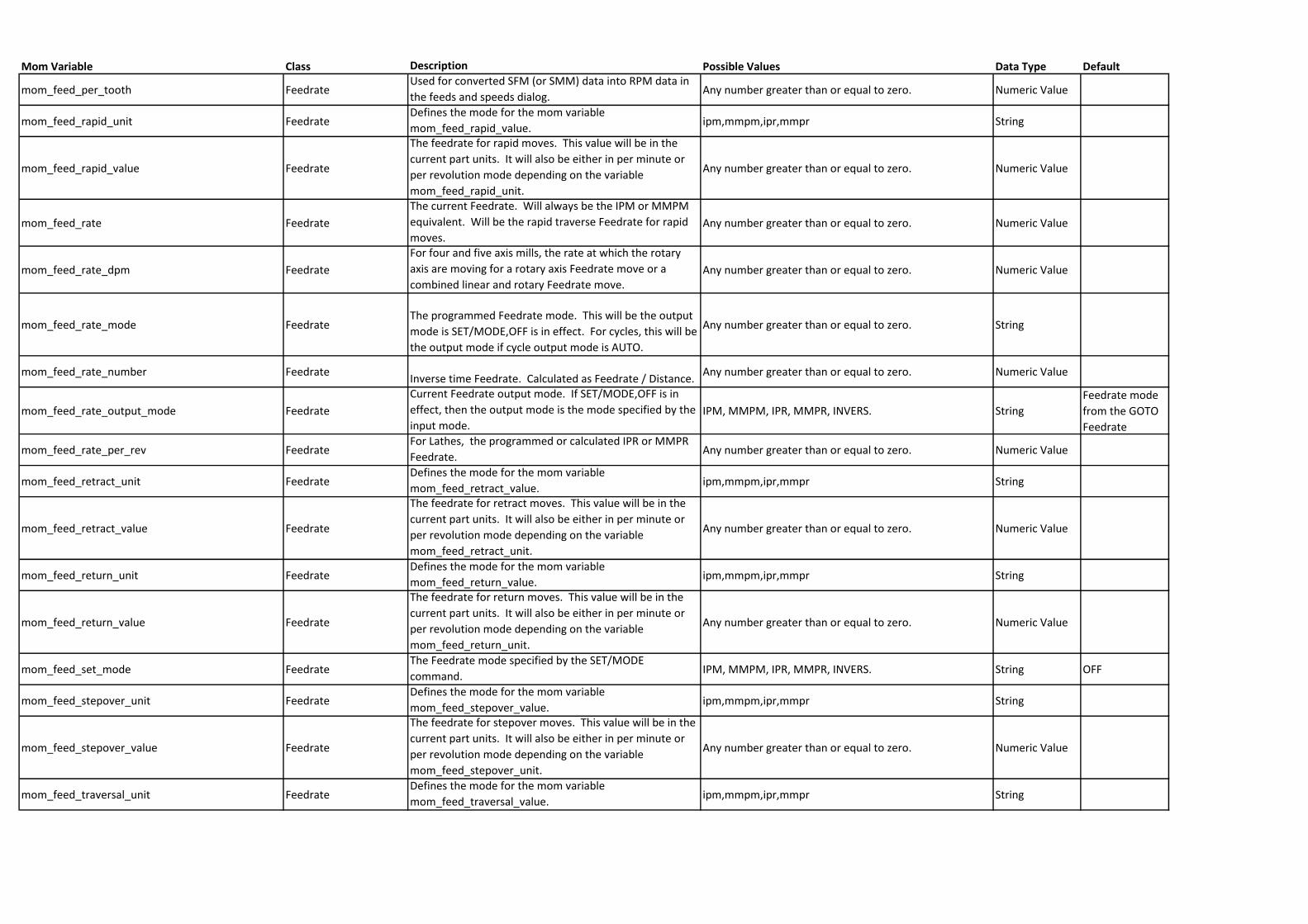
mom_feed_per_tooth FeedrateUsed for converted SFM (or SMM) data into RPM data in
the feeds and speeds dialog.Any number greater than or equal to zero. Numeric Value
mom_feed_rapid_unit FeedrateDefines the mode for the mom variable
mom_feed_rapid_value.ipm,mmpm,ipr,mmpr String
mom_feed_rapid_value Feedrate
The feedrate for rapid moves. This value will be in the
current part units. It will also be either in per minute or
per revolution mode depending on the variable
mom_feed_rapid_unit.
Any number greater than or equal to zero. Numeric Value
mom_feed_rate Feedrate
The current Feedrate. Will always be the IPM or MMPM
equivalent. Will be the rapid traverse Feedrate for rapid
moves.Any number greater than or equal to zero. Numeric Value
mom_feed_rate_dpm Feedrate
For four and five axis mills, the rate at which the rotary
axis are moving for a rotary axis Feedrate move or a
combined linear and rotary Feedrate move.Any number greater than or equal to zero. Numeric Value
mom_feed_rate_mode FeedrateThe programmed Feedrate mode. This will be the output
mode is SET/MODE,OFF is in effect. For cycles, this will be
the output mode if cycle output mode is AUTO.
Any number greater than or equal to zero. String
mom_feed_rate_number FeedrateInverse time Feedrate. Calculated as Feedrate / Distance.
Any number greater than or equal to zero. Numeric Value
mom_feed_rate_output_mode Feedrate
Current Feedrate output mode. If SET/MODE,OFF is in
effect, then the output mode is the mode specified by the
input mode.IPM, MMPM, IPR, MMPR, INVERS. String
Feedrate mode
from the GOTO
Feedrate
mom_feed_rate_per_rev FeedrateFor Lathes, the programmed or calculated IPR or MMPR
Feedrate.Any number greater than or equal to zero. Numeric Value
mom_feed_retract_unit FeedrateDefines the mode for the mom variable
mom_feed_retract_value.ipm,mmpm,ipr,mmpr String
mom_feed_retract_value Feedrate
The feedrate for retract moves. This value will be in the
current part units. It will also be either in per minute or
per revolution mode depending on the variable
mom_feed_retract_unit.
Any number greater than or equal to zero. Numeric Value
mom_feed_return_unit FeedrateDefines the mode for the mom variable
mom_feed_return_value.ipm,mmpm,ipr,mmpr String
mom_feed_return_value Feedrate
The feedrate for return moves. This value will be in the
current part units. It will also be either in per minute or
per revolution mode depending on the variable
mom_feed_return_unit.
Any number greater than or equal to zero. Numeric Value
mom_feed_set_mode FeedrateThe Feedrate mode specified by the SET/MODE
command.IPM, MMPM, IPR, MMPR, INVERS. String OFF
mom_feed_stepover_unit FeedrateDefines the mode for the mom variable
mom_feed_stepover_value.ipm,mmpm,ipr,mmpr String
mom_feed_stepover_value Feedrate
The feedrate for stepover moves. This value will be in the
current part units. It will also be either in per minute or
per revolution mode depending on the variable
mom_feed_stepover_unit.
Any number greater than or equal to zero. Numeric Value
mom_feed_traversal_unit FeedrateDefines the mode for the mom variable
mom_feed_traversal_value.ipm,mmpm,ipr,mmpr String
Mom Variable Class Description Possible Values Data Type Default
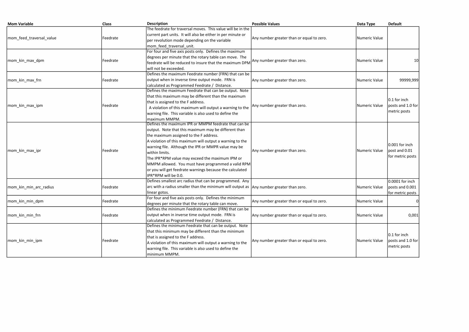
mom_feed_traversal_value Feedrate
The feedrate for traversal moves. This value will be in the
current part units. It will also be either in per minute or
per revolution mode depending on the variable
mom_feed_traversal_unit.
Any number greater than or equal to zero. Numeric Value
mom_kin_max_dpm Feedrate
For four and five axis posts only. Defines the maximum
degrees per minute that the rotary table can move. The
feedrate will be reduced to insure that the maximum DPM
will not be exceeded.
Any number greater than zero. Numeric Value 10
mom_kin_max_frn Feedrate
Defines the maximum Feedrate number (FRN) that can be
output when in inverse time output mode. FRN is
calculated as Programmed Feedrate / Distance.Any number greater than zero. Numeric Value 99999,999
mom_kin_max_ipm Feedrate
Defines the maximum Feedrate that can be output. Note
that this maximum may be different than the maximum
that is assigned to the F address.
A violation of this maximum will output a warning to the
warning file. This variable is also used to define the
maximum MMPM.
Any number greater than zero. Numeric Value
0.1 for inch
posts and 1.0 for
metric posts
mom_kin_max_ipr Feedrate
Defines the maximum IPR or MMPM feedrate that can be
output. Note that this maximum may be different than
the maximum assigned to the F address.
A violation of this maximum will output a warning to the
warning file. Although the IPR or MMPR value may be
within limits.
The IPR*RPM value may exceed the maximum IPM or
MMPM allowed. You must have programmed a valid RPM
or you will get feedrate warnings because the calculated
IPR*RPM will be 0.0.
Any number greater than zero. Numeric Value
0.001 for inch
post and 0.01
for metric posts
mom_kin_min_arc_radius Feedrate
Defines smallest arc radius that can be programmed. Any
arc with a radius smaller than the minimum will output as
linear gotos.Any number greater than zero. Numeric Value
0.0001 for inch
posts and 0.001
for metric posts
mom_kin_min_dpm FeedrateFor four and five axis posts only. Defines the minimum
degrees per minute that the rotary table can move. Any number greater than or equal to zero. Numeric Value 0
mom_kin_min_frn Feedrate
Defines the minimum Feedrate number (FRN) that can be
output when in inverse time output mode. FRN is
calculated as Programmed Feedrate / Distance.Any number greater than or equal to zero. Numeric Value 0,001
mom_kin_min_ipm Feedrate
Defines the minimum Feedrate that can be output. Note
that this minimum may be different than the minimum
that is assigned to the F address.
A violation of this maximum will output a warning to the
warning file. This variable is also used to define the
minimum MMPM.
Any number greater than or equal to zero. Numeric Value
0.1 for inch
posts and 1.0 for
metric posts
Mom Variable Class Description Possible Values Data Type Default
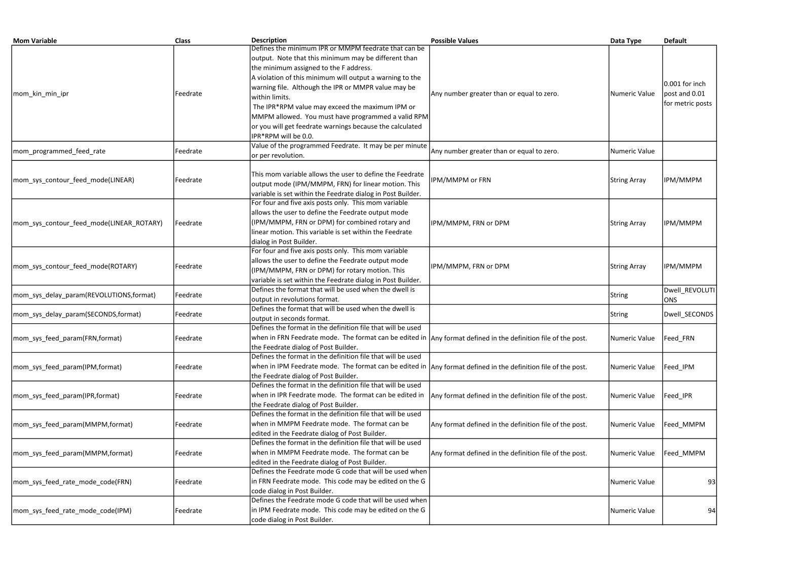
mom_kin_min_ipr Feedrate
Defines the minimum IPR or MMPM feedrate that can be
output. Note that this minimum may be different than
the minimum assigned to the F address.
A violation of this minimum will output a warning to the
warning file. Although the IPR or MMPR value may be
within limits.
The IPR*RPM value may exceed the maximum IPM or
MMPM allowed. You must have programmed a valid RPM
or you will get feedrate warnings because the calculated
IPR*RPM will be 0.0.
Any number greater than or equal to zero. Numeric Value
0.001 for inch
post and 0.01
for metric posts
mom_programmed_feed_rate FeedrateValue of the programmed Feedrate. It may be per minute
or per revolution.Any number greater than or equal to zero. Numeric Value
mom_sys_contour_feed_mode(LINEAR) FeedrateThis mom variable allows the user to define the Feedrate
output mode (IPM/MMPM, FRN) for linear motion. This
variable is set within the Feedrate dialog in Post Builder.
IPM/MMPM or FRN String Array IPM/MMPM
mom_sys_contour_feed_mode(LINEAR_ROTARY) Feedrate
For four and five axis posts only. This mom variable
allows the user to define the Feedrate output mode
(IPM/MMPM, FRN or DPM) for combined rotary and
linear motion. This variable is set within the Feedrate
dialog in Post Builder.
IPM/MMPM, FRN or DPM String Array IPM/MMPM
mom_sys_contour_feed_mode(ROTARY) Feedrate
For four and five axis posts only. This mom variable
allows the user to define the Feedrate output mode
(IPM/MMPM, FRN or DPM) for rotary motion. This
variable is set within the Feedrate dialog in Post Builder.
IPM/MMPM, FRN or DPM String Array IPM/MMPM
mom_sys_delay_param(REVOLUTIONS,format) FeedrateDefines the format that will be used when the dwell is
output in revolutions format.String
Dwell_REVOLUTI
ONS
mom_sys_delay_param(SECONDS,format) FeedrateDefines the format that will be used when the dwell is
output in seconds format.String Dwell_SECONDS
mom_sys_feed_param(FRN,format) Feedrate
Defines the format in the definition file that will be used
when in FRN Feedrate mode. The format can be edited in
the Feedrate dialog of Post Builder.Any format defined in the definition file of the post. Numeric Value Feed_FRN
mom_sys_feed_param(IPM,format) Feedrate
Defines the format in the definition file that will be used
when in IPM Feedrate mode. The format can be edited in
the Feedrate dialog of Post Builder.Any format defined in the definition file of the post. Numeric Value Feed_IPM
mom_sys_feed_param(IPR,format) Feedrate
Defines the format in the definition file that will be used
when in IPR Feedrate mode. The format can be edited in
the Feedrate dialog of Post Builder.Any format defined in the definition file of the post. Numeric Value Feed_IPR
mom_sys_feed_param(MMPM,format) Feedrate
Defines the format in the definition file that will be used
when in MMPM Feedrate mode. The format can be
edited in the Feedrate dialog of Post Builder.Any format defined in the definition file of the post. Numeric Value Feed_MMPM
mom_sys_feed_param(MMPM,format) Feedrate
Defines the format in the definition file that will be used
when in MMPM Feedrate mode. The format can be
edited in the Feedrate dialog of Post Builder.Any format defined in the definition file of the post. Numeric Value Feed_MMPM
mom_sys_feed_rate_mode_code(FRN) Feedrate
Defines the Feedrate mode G code that will be used when
in FRN Feedrate mode. This code may be edited on the G
code dialog in Post Builder.Numeric Value 93
mom_sys_feed_rate_mode_code(IPM) Feedrate
Defines the Feedrate mode G code that will be used when
in IPM Feedrate mode. This code may be edited on the G
code dialog in Post Builder.Numeric Value 94
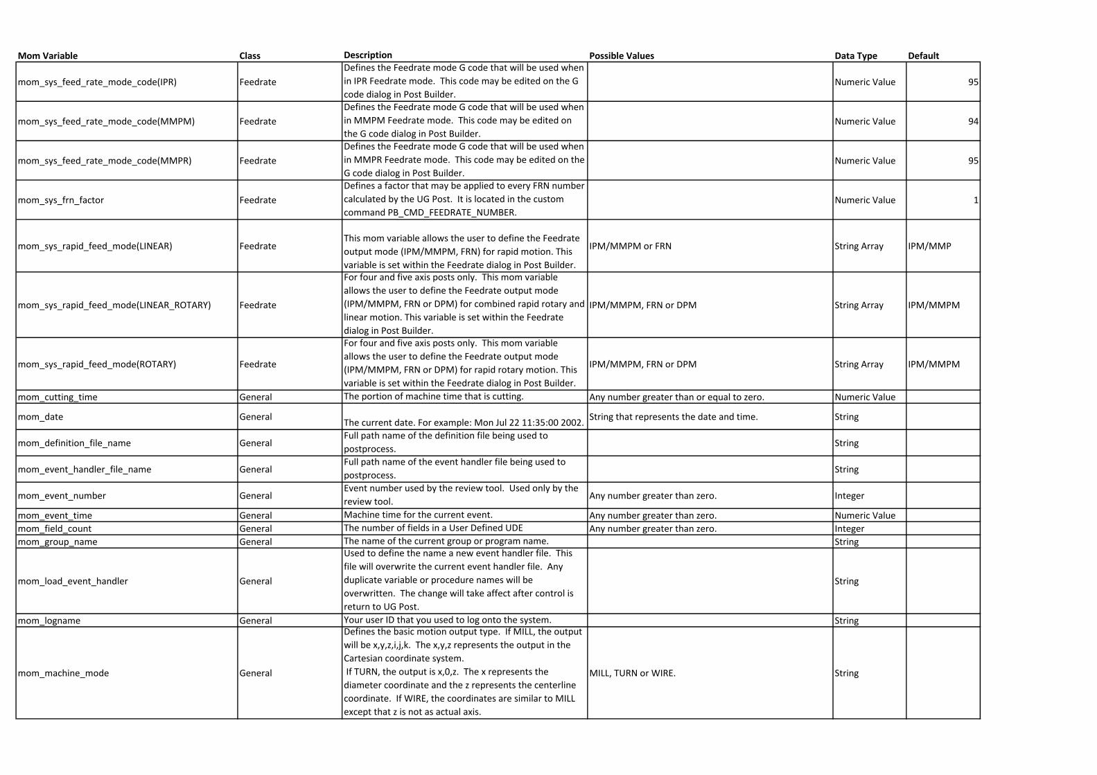
Mom Variable Class Description Possible Values Data Type Default
mom_sys_feed_rate_mode_code(IPR) Feedrate
Defines the Feedrate mode G code that will be used when
in IPR Feedrate mode. This code may be edited on the G
code dialog in Post Builder.Numeric Value 95
mom_sys_feed_rate_mode_code(MMPM) Feedrate
Defines the Feedrate mode G code that will be used when
in MMPM Feedrate mode. This code may be edited on
the G code dialog in Post Builder.Numeric Value 94
mom_sys_feed_rate_mode_code(MMPR) Feedrate
Defines the Feedrate mode G code that will be used when
in MMPR Feedrate mode. This code may be edited on the
G code dialog in Post Builder.Numeric Value 95
mom_sys_frn_factor Feedrate
Defines a factor that may be applied to every FRN number
calculated by the UG Post. It is located in the custom
command PB_CMD_FEEDRATE_NUMBER.Numeric Value 1
mom_sys_rapid_feed_mode(LINEAR) FeedrateThis mom variable allows the user to define the Feedrate
output mode (IPM/MMPM, FRN) for rapid motion. This
variable is set within the Feedrate dialog in Post Builder.
IPM/MMPM or FRN String Array IPM/MMP
mom_sys_rapid_feed_mode(LINEAR_ROTARY) Feedrate
For four and five axis posts only. This mom variable
allows the user to define the Feedrate output mode
(IPM/MMPM, FRN or DPM) for combined rapid rotary and
linear motion. This variable is set within the Feedrate
dialog in Post Builder.
IPM/MMPM, FRN or DPM String Array IPM/MMPM
mom_sys_rapid_feed_mode(ROTARY) Feedrate
For four and five axis posts only. This mom variable
allows the user to define the Feedrate output mode
(IPM/MMPM, FRN or DPM) for rapid rotary motion. This
variable is set within the Feedrate dialog in Post Builder.
IPM/MMPM, FRN or DPM String Array IPM/MMPM
mom_cutting_time General The portion of machine time that is cutting. Any number greater than or equal to zero. Numeric Value
mom_date GeneralThe current date. For example: Mon Jul 22 11:35:00 2002.
String that represents the date and time. String
mom_definition_file_name GeneralFull path name of the definition file being used to
postprocess.String
mom_event_handler_file_name GeneralFull path name of the event handler file being used to
postprocess.String
mom_event_number GeneralEvent number used by the review tool. Used only by the
review tool.Any number greater than zero. Integer
mom_event_time General Machine time for the current event. Any number greater than zero. Numeric Value
mom_field_count General The number of fields in a User Defined UDE Any number greater than zero. Integer
mom_group_name General The name of the current group or program name. String
mom_load_event_handler General
Used to define the name a new event handler file. This
file will overwrite the current event handler file. Any
duplicate variable or procedure names will be
overwritten. The change will take affect after control is
return to UG Post.
String
mom_logname General Your user ID that you used to log onto the system. String
mom_machine_mode General
Defines the basic motion output type. If MILL, the output
will be x,y,z,i,j,k. The x,y,z represents the output in the
Cartesian coordinate system.
If TURN, the output is x,0,z. The x represents the
diameter coordinate and the z represents the centerline
coordinate. If WIRE, the coordinates are similar to MILL
except that z is not as actual axis.
MILL, TURN or WIRE. String
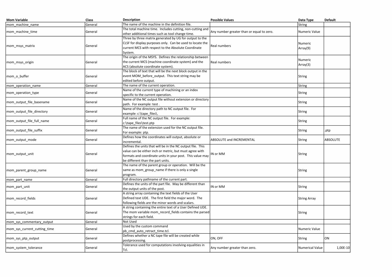
Mom Variable Class Description Possible Values Data Type Default
mom_machine_name General The name of the machine in the definition file. String
mom_machine_time GeneralThe total machine time. Includes cutting, non-cutting and
other additional times such as tool change time.Any number greater than or equal to zero. Numeric Value
mom_msys_matrix General
Three by three matrix generated by UG for output to the
CLSF for display purposes only. Can be used to locate the
current MCS with respect to the Absolute Coordinate
System.
Real numbersNumeric
Array(9)
mom_msys_origin General
The origin of the MSYS. Defines the relationship between
the current MCS (machine coordinate system) and the
ACS (absolute coordinate system).Real numbers
Numeric
Array(3)
mom_o_buffer General
The block of text that will be the next block output in the
event MOM_before_output. This text string may be
edited before output.String
mom_operation_name General The name of the current operation. String
mom_operation_type GeneralName of the current type of machining or an index
specific to the current operation.String
mom_output_file_basename GeneralName of the NC output file without extension or directory
path. For example: test .String
mom_output_file_directory GeneralName of the directory path to NC output file. For
example: c:\tape_files\.String
mom_output_file_full_name GeneralFull name of the NC output file. For example:
c:\tape_files\test.ptpString
mom_output_file_suffix GeneralThe name of the extension used for the NC output file.
For example: ptp.String .ptp
mom_output_mode GeneralDefines how the coordinates will output, absolute or
incremental.ABSOLUTE and INCREMENTAL String ABSOLUTE
mom_output_unit General
Defines the units that will be in the NC output file. This
value can be either inch or metric, but must agree with
formats and coordinate units in your post. This value may
be different than the part units.
IN or MM String
mom_parent_group_name General
The name of the parent group or operation. Will be the
same as mom_group_name if there is only a single
program.String
mom_part_name General Full directory pathname of the current part.
mom_part_unit GeneralDefines the units of the part file. May be different than
the output units of the post.IN or MM String
mom_record_fields General
A string array containing the text fields of the User
Defined text UDE. The first field the major word. The
following fields are the minor words and scalars. String Array
mom_record_text General
A string containing the entire text of a User Defined UDE.
The mom variable mom_record_fields contains the parsed
strings for each field.String
mom_sys_commentary_output General Not Used
mom_sys_current_cutting_time GeneralUsed by the custom command
pb_cmd_auto_retract_time.tcl.Numeric Value
mom_sys_ptp_output GeneralDefines whether a NC tape file will be created while
postprocessing.ON, OFF String ON
mom_system_tolerance GeneralTolerance used for computations involving equalities in
Tcl.Any number greater than zero. Numerical Value 1,00E-10
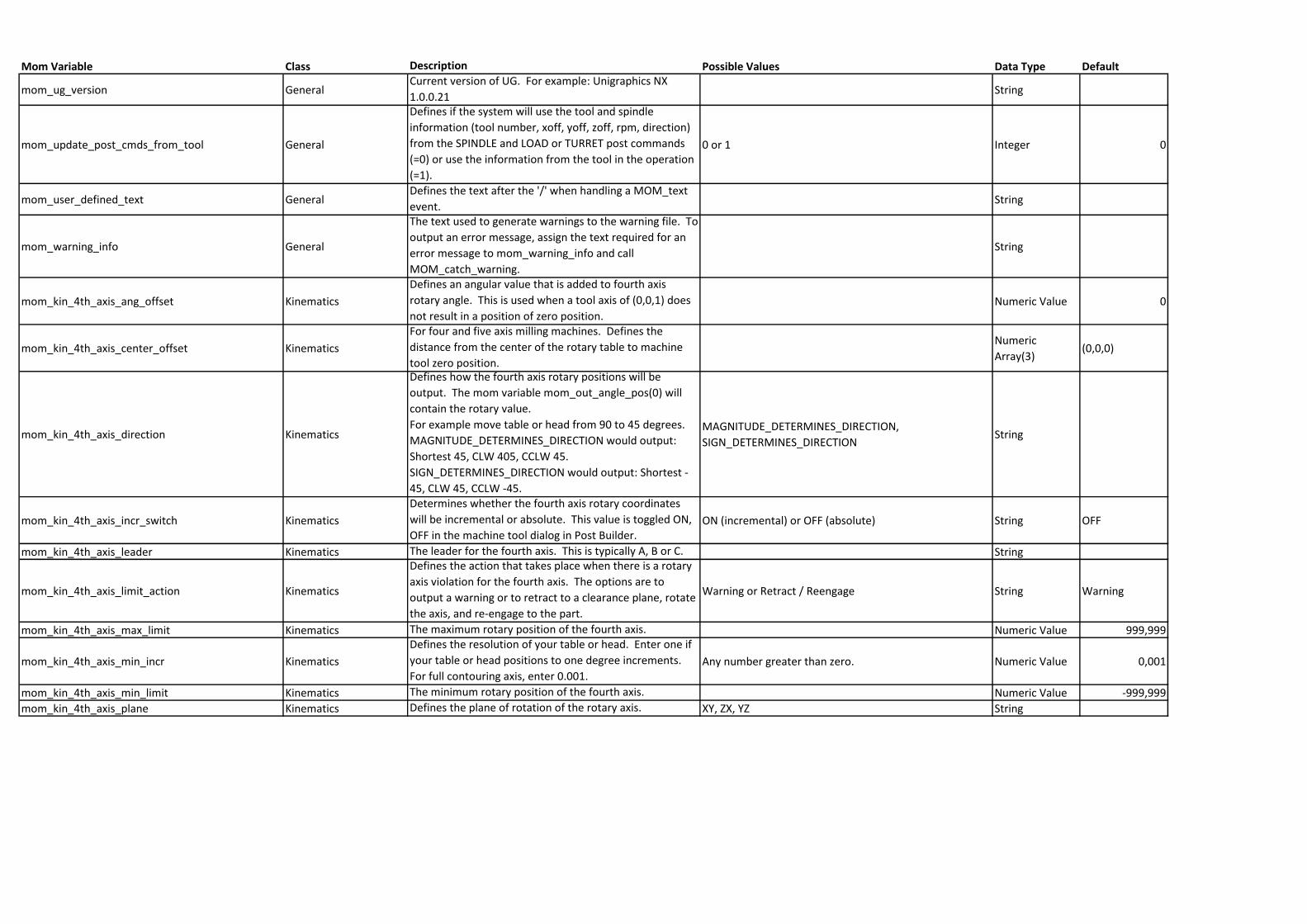
Mom Variable Class Description Possible Values Data Type Default
mom_ug_version GeneralCurrent version of UG. For example: Unigraphics NX
1.0.0.21String
mom_update_post_cmds_from_tool General
Defines if the system will use the tool and spindle
information (tool number, xoff, yoff, zoff, rpm, direction)
from the SPINDLE and LOAD or TURRET post commands
(=0) or use the information from the tool in the operation
(=1).
0 or 1 Integer 0
mom_user_defined_text GeneralDefines the text after the '/' when handling a MOM_text
event.String
mom_warning_info General
The text used to generate warnings to the warning file. To
output an error message, assign the text required for an
error message to mom_warning_info and call
MOM_catch_warning.
String
mom_kin_4th_axis_ang_offset Kinematics
Defines an angular value that is added to fourth axis
rotary angle. This is used when a tool axis of (0,0,1) does
not result in a position of zero position.Numeric Value 0
mom_kin_4th_axis_center_offset Kinematics
For four and five axis milling machines. Defines the
distance from the center of the rotary table to machine
tool zero position.
Numeric
Array(3)(0,0,0)
mom_kin_4th_axis_direction Kinematics
Defines how the fourth axis rotary positions will be
output. The mom variable mom_out_angle_pos(0) will
contain the rotary value.
For example move table or head from 90 to 45 degrees.
MAGNITUDE_DETERMINES_DIRECTION would output:
Shortest 45, CLW 405, CCLW 45.
SIGN_DETERMINES_DIRECTION would output: Shortest -
45, CLW 45, CCLW -45.
MAGNITUDE_DETERMINES_DIRECTION,
SIGN_DETERMINES_DIRECTIONString
mom_kin_4th_axis_incr_switch Kinematics
Determines whether the fourth axis rotary coordinates
will be incremental or absolute. This value is toggled ON,
OFF in the machine tool dialog in Post Builder.ON (incremental) or OFF (absolute) String OFF
mom_kin_4th_axis_leader Kinematics The leader for the fourth axis. This is typically A, B or C. String
mom_kin_4th_axis_limit_action Kinematics
Defines the action that takes place when there is a rotary
axis violation for the fourth axis. The options are to
output a warning or to retract to a clearance plane, rotate
the axis, and re-engage to the part.
Warning or Retract / Reengage String Warning
mom_kin_4th_axis_max_limit Kinematics The maximum rotary position of the fourth axis. Numeric Value 999,999
mom_kin_4th_axis_min_incr Kinematics
Defines the resolution of your table or head. Enter one if
your table or head positions to one degree increments.
For full contouring axis, enter 0.001.Any number greater than zero. Numeric Value 0,001
mom_kin_4th_axis_min_limit Kinematics The minimum rotary position of the fourth axis. Numeric Value -999,999
mom_kin_4th_axis_plane Kinematics Defines the plane of rotation of the rotary axis. XY, ZX, YZ String
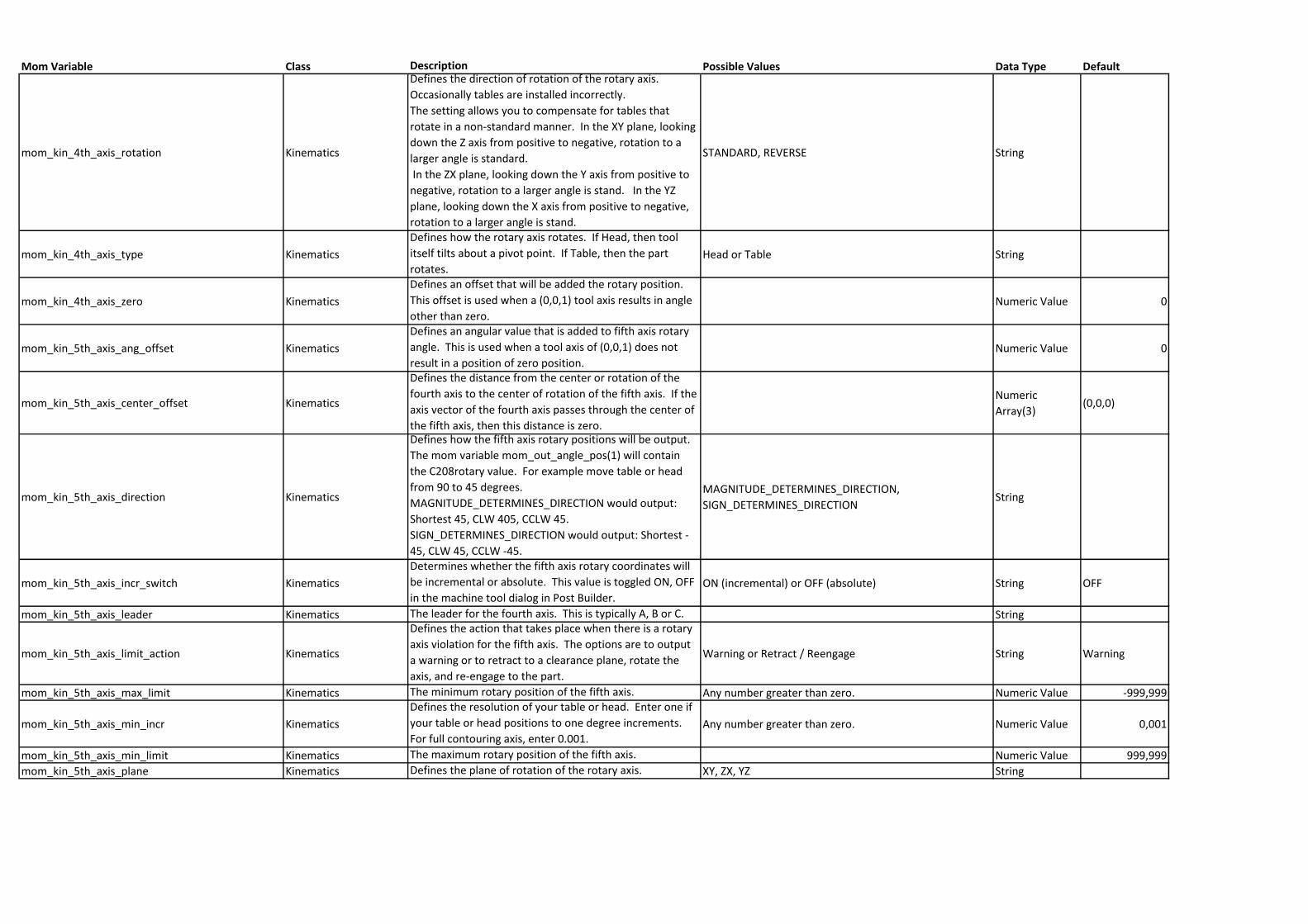
Mom Variable Class Description Possible Values Data Type Default
mom_kin_4th_axis_rotation Kinematics
Defines the direction of rotation of the rotary axis.
Occasionally tables are installed incorrectly.
The setting allows you to compensate for tables that
rotate in a non-standard manner. In the XY plane, looking
down the Z axis from positive to negative, rotation to a
larger angle is standard.
In the ZX plane, looking down the Y axis from positive to
negative, rotation to a larger angle is stand. In the YZ
plane, looking down the X axis from positive to negative,
rotation to a larger angle is stand.
STANDARD, REVERSE String
mom_kin_4th_axis_type Kinematics
Defines how the rotary axis rotates. If Head, then tool
itself tilts about a pivot point. If Table, then the part
rotates.Head or Table String
mom_kin_4th_axis_zero Kinematics
Defines an offset that will be added the rotary position.
This offset is used when a (0,0,1) tool axis results in angle
other than zero.Numeric Value 0
mom_kin_5th_axis_ang_offset Kinematics
Defines an angular value that is added to fifth axis rotary
angle. This is used when a tool axis of (0,0,1) does not
result in a position of zero position.Numeric Value 0
mom_kin_5th_axis_center_offset Kinematics
Defines the distance from the center or rotation of the
fourth axis to the center of rotation of the fifth axis. If the
axis vector of the fourth axis passes through the center of
the fifth axis, then this distance is zero.
Numeric
Array(3)(0,0,0)
mom_kin_5th_axis_direction Kinematics
Defines how the fifth axis rotary positions will be output.
The mom variable mom_out_angle_pos(1) will contain
the C208rotary value. For example move table or head
from 90 to 45 degrees.
MAGNITUDE_DETERMINES_DIRECTION would output:
Shortest 45, CLW 405, CCLW 45.
SIGN_DETERMINES_DIRECTION would output: Shortest -
45, CLW 45, CCLW -45.
MAGNITUDE_DETERMINES_DIRECTION,
SIGN_DETERMINES_DIRECTIONString
mom_kin_5th_axis_incr_switch Kinematics
Determines whether the fifth axis rotary coordinates will
be incremental or absolute. This value is toggled ON, OFF
in the machine tool dialog in Post Builder.ON (incremental) or OFF (absolute) String OFF
mom_kin_5th_axis_leader Kinematics The leader for the fourth axis. This is typically A, B or C. String
mom_kin_5th_axis_limit_action Kinematics
Defines the action that takes place when there is a rotary
axis violation for the fifth axis. The options are to output
a warning or to retract to a clearance plane, rotate the
axis, and re-engage to the part.
Warning or Retract / Reengage String Warning
mom_kin_5th_axis_max_limit Kinematics The minimum rotary position of the fifth axis. Any number greater than zero. Numeric Value -999,999
mom_kin_5th_axis_min_incr Kinematics
Defines the resolution of your table or head. Enter one if
your table or head positions to one degree increments.
For full contouring axis, enter 0.001.Any number greater than zero. Numeric Value 0,001
mom_kin_5th_axis_min_limit Kinematics The maximum rotary position of the fifth axis. Numeric Value 999,999
mom_kin_5th_axis_plane Kinematics Defines the plane of rotation of the rotary axis. XY, ZX, YZ String
Mom Variable Class Description Possible Values Data Type Default
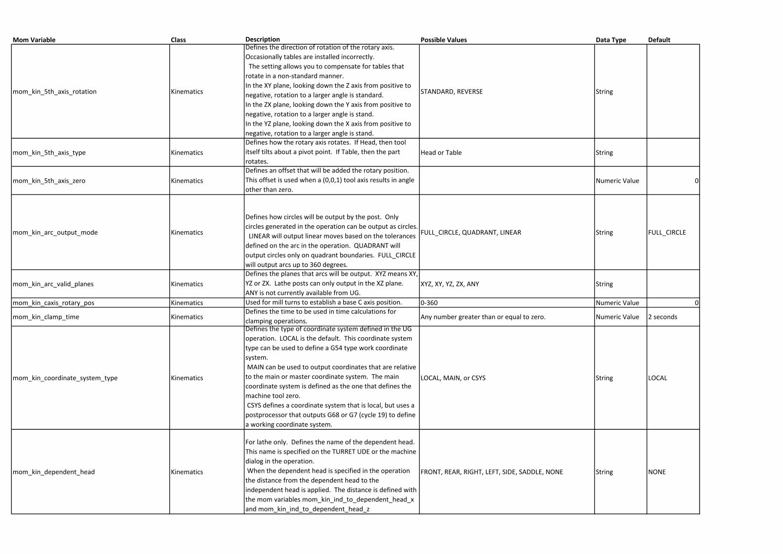
mom_kin_5th_axis_rotation Kinematics
Defines the direction of rotation of the rotary axis.
Occasionally tables are installed incorrectly.
The setting allows you to compensate for tables that
rotate in a non-standard manner.
In the XY plane, looking down the Z axis from positive to
negative, rotation to a larger angle is standard.
In the ZX plane, looking down the Y axis from positive to
negative, rotation to a larger angle is stand.
In the YZ plane, looking down the X axis from positive to
negative, rotation to a larger angle is stand.
STANDARD, REVERSE String
mom_kin_5th_axis_type Kinematics
Defines how the rotary axis rotates. If Head, then tool
itself tilts about a pivot point. If Table, then the part
rotates.Head or Table String
mom_kin_5th_axis_zero Kinematics
Defines an offset that will be added the rotary position.
This offset is used when a (0,0,1) tool axis results in angle
other than zero.Numeric Value 0
mom_kin_arc_output_mode Kinematics
Defines how circles will be output by the post. Only
circles generated in the operation can be output as circles.
LINEAR will output linear moves based on the tolerances
defined on the arc in the operation. QUADRANT will
output circles only on quadrant boundaries. FULL_CIRCLE
will output arcs up to 360 degrees.
FULL_CIRCLE, QUADRANT, LINEAR String FULL_CIRCLE
mom_kin_arc_valid_planes Kinematics
Defines the planes that arcs will be output. XYZ means XY,
YZ or ZX. Lathe posts can only output in the XZ plane.
ANY is not currently available from UG.XYZ, XY, YZ, ZX, ANY String
mom_kin_caxis_rotary_pos Kinematics Used for mill turns to establish a base C axis position. 0-360 Numeric Value 0
mom_kin_clamp_time KinematicsDefines the time to be used in time calculations for
clamping operations.Any number greater than or equal to zero. Numeric Value 2 seconds
mom_kin_coordinate_system_type Kinematics
Defines the type of coordinate system defined in the UG
operation. LOCAL is the default. This coordinate system
type can be used to define a G54 type work coordinate
system.
MAIN can be used to output coordinates that are relative
to the main or master coordinate system. The main
coordinate system is defined as the one that defines the
machine tool zero.
CSYS defines a coordinate system that is local, but uses a
postprocessor that outputs G68 or G7 (cycle 19) to define
a working coordinate system.
LOCAL, MAIN, or CSYS String LOCAL
mom_kin_dependent_head Kinematics
For lathe only. Defines the name of the dependent head.
This name is specified on the TURRET UDE or the machine
dialog in the operation.
When the dependent head is specified in the operation
the distance from the dependent head to the
independent head is applied. The distance is defined with
the mom variables mom_kin_ind_to_dependent_head_x
and mom_kin_ind_to_dependent_head_z
FRONT, REAR, RIGHT, LEFT, SIDE, SADDLE, NONE String NONE
Mom Variable Class Description Possible Values Data Type Default
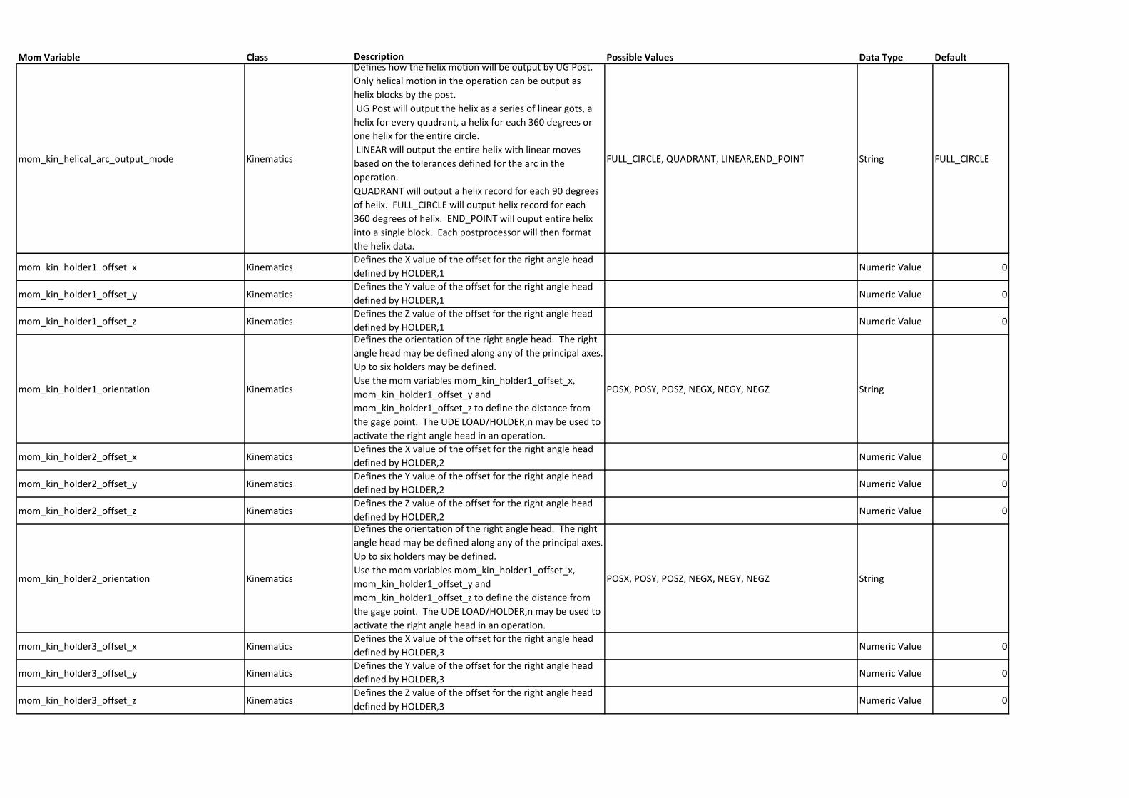
mom_kin_helical_arc_output_mode Kinematics
Defines how the helix motion will be output by UG Post.
Only helical motion in the operation can be output as
helix blocks by the post.
UG Post will output the helix as a series of linear gots, a
helix for every quadrant, a helix for each 360 degrees or
one helix for the entire circle.
LINEAR will output the entire helix with linear moves
based on the tolerances defined for the arc in the
operation.
QUADRANT will output a helix record for each 90 degrees
of helix. FULL_CIRCLE will output helix record for each
360 degrees of helix. END_POINT will ouput entire helix
into a single block. Each postprocessor will then format
the helix data.
FULL_CIRCLE, QUADRANT, LINEAR,END_POINT String FULL_CIRCLE
mom_kin_holder1_offset_x KinematicsDefines the X value of the offset for the right angle head
defined by HOLDER,1Numeric Value 0
mom_kin_holder1_offset_y KinematicsDefines the Y value of the offset for the right angle head
defined by HOLDER,1Numeric Value 0
mom_kin_holder1_offset_z KinematicsDefines the Z value of the offset for the right angle head
defined by HOLDER,1Numeric Value 0
mom_kin_holder1_orientation Kinematics
Defines the orientation of the right angle head. The right
angle head may be defined along any of the principal axes.
Up to six holders may be defined.
Use the mom variables mom_kin_holder1_offset_x,
mom_kin_holder1_offset_y and
mom_kin_holder1_offset_z to define the distance from
the gage point. The UDE LOAD/HOLDER,n may be used to
activate the right angle head in an operation.
POSX, POSY, POSZ, NEGX, NEGY, NEGZ String
mom_kin_holder2_offset_x KinematicsDefines the X value of the offset for the right angle head
defined by HOLDER,2Numeric Value 0
mom_kin_holder2_offset_y KinematicsDefines the Y value of the offset for the right angle head
defined by HOLDER,2Numeric Value 0
mom_kin_holder2_offset_z KinematicsDefines the Z value of the offset for the right angle head
defined by HOLDER,2Numeric Value 0
mom_kin_holder2_orientation Kinematics
Defines the orientation of the right angle head. The right
angle head may be defined along any of the principal axes.
Up to six holders may be defined.
Use the mom variables mom_kin_holder1_offset_x,
mom_kin_holder1_offset_y and
mom_kin_holder1_offset_z to define the distance from
the gage point. The UDE LOAD/HOLDER,n may be used to
activate the right angle head in an operation.
POSX, POSY, POSZ, NEGX, NEGY, NEGZ String
mom_kin_holder3_offset_x KinematicsDefines the X value of the offset for the right angle head
defined by HOLDER,3Numeric Value 0
mom_kin_holder3_offset_y KinematicsDefines the Y value of the offset for the right angle head
defined by HOLDER,3Numeric Value 0
mom_kin_holder3_offset_z KinematicsDefines the Z value of the offset for the right angle head
defined by HOLDER,3Numeric Value 0
Mom Variable Class Description Possible Values Data Type Default
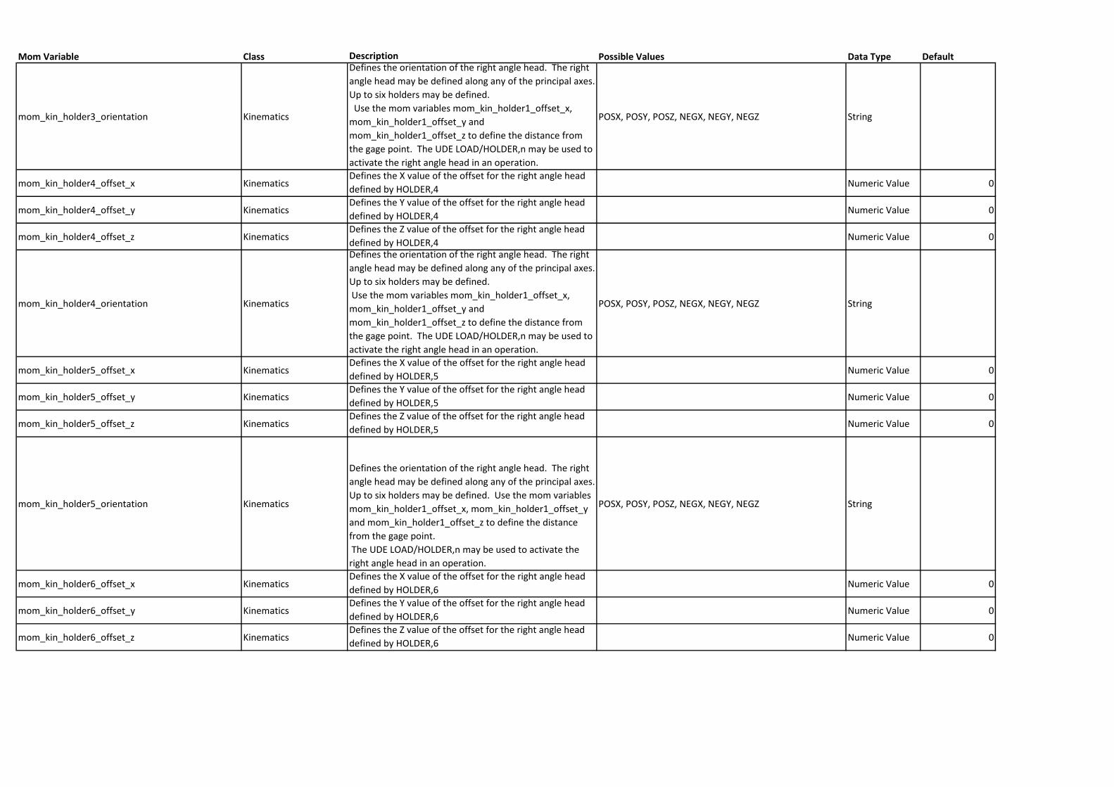
mom_kin_holder3_orientation Kinematics
Defines the orientation of the right angle head. The right
angle head may be defined along any of the principal axes.
Up to six holders may be defined.
Use the mom variables mom_kin_holder1_offset_x,
mom_kin_holder1_offset_y and
mom_kin_holder1_offset_z to define the distance from
the gage point. The UDE LOAD/HOLDER,n may be used to
activate the right angle head in an operation.
POSX, POSY, POSZ, NEGX, NEGY, NEGZ String
mom_kin_holder4_offset_x KinematicsDefines the X value of the offset for the right angle head
defined by HOLDER,4Numeric Value 0
mom_kin_holder4_offset_y KinematicsDefines the Y value of the offset for the right angle head
defined by HOLDER,4Numeric Value 0
mom_kin_holder4_offset_z KinematicsDefines the Z value of the offset for the right angle head
defined by HOLDER,4Numeric Value 0
mom_kin_holder4_orientation Kinematics
Defines the orientation of the right angle head. The right
angle head may be defined along any of the principal axes.
Up to six holders may be defined.
Use the mom variables mom_kin_holder1_offset_x,
mom_kin_holder1_offset_y and
mom_kin_holder1_offset_z to define the distance from
the gage point. The UDE LOAD/HOLDER,n may be used to
activate the right angle head in an operation.
POSX, POSY, POSZ, NEGX, NEGY, NEGZ String
mom_kin_holder5_offset_x KinematicsDefines the X value of the offset for the right angle head
defined by HOLDER,5Numeric Value 0
mom_kin_holder5_offset_y KinematicsDefines the Y value of the offset for the right angle head
defined by HOLDER,5Numeric Value 0
mom_kin_holder5_offset_z KinematicsDefines the Z value of the offset for the right angle head
defined by HOLDER,5Numeric Value 0
mom_kin_holder5_orientation Kinematics
Defines the orientation of the right angle head. The right
angle head may be defined along any of the principal axes.
Up to six holders may be defined. Use the mom variables
mom_kin_holder1_offset_x, mom_kin_holder1_offset_y
and mom_kin_holder1_offset_z to define the distance
from the gage point.
The UDE LOAD/HOLDER,n may be used to activate the
right angle head in an operation.
POSX, POSY, POSZ, NEGX, NEGY, NEGZ String
mom_kin_holder6_offset_x KinematicsDefines the X value of the offset for the right angle head
defined by HOLDER,6Numeric Value 0
mom_kin_holder6_offset_y KinematicsDefines the Y value of the offset for the right angle head
defined by HOLDER,6Numeric Value 0
mom_kin_holder6_offset_z KinematicsDefines the Z value of the offset for the right angle head
defined by HOLDER,6Numeric Value 0
Mom Variable Class Description Possible Values Data Type Default
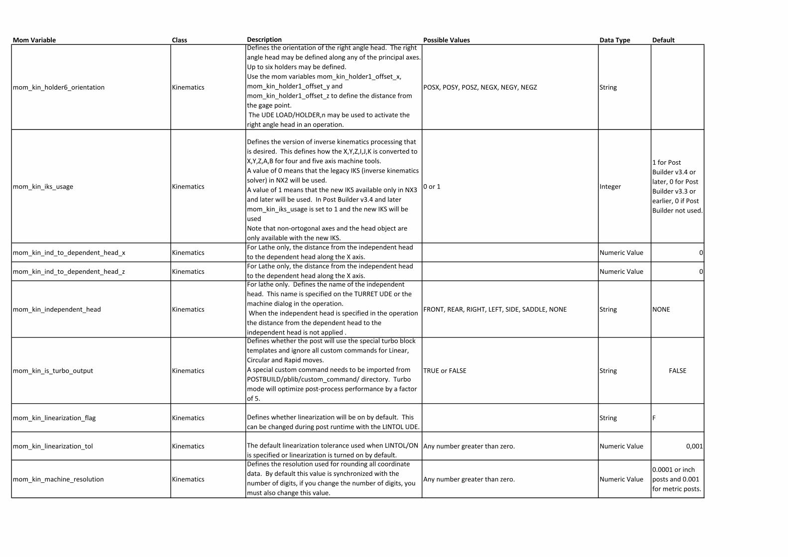
mom_kin_holder6_orientation Kinematics
Defines the orientation of the right angle head. The right
angle head may be defined along any of the principal axes.
Up to six holders may be defined.
Use the mom variables mom_kin_holder1_offset_x,
mom_kin_holder1_offset_y and
mom_kin_holder1_offset_z to define the distance from
the gage point.
The UDE LOAD/HOLDER,n may be used to activate the
right angle head in an operation.
POSX, POSY, POSZ, NEGX, NEGY, NEGZ String
mom_kin_iks_usage Kinematics
Defines the version of inverse kinematics processing that
is desired. This defines how the X,Y,Z,I,J,K is converted to
X,Y,Z,A,B for four and five axis machine tools.
A value of 0 means that the legacy IKS (inverse kinematics
solver) in NX2 will be used.
A value of 1 means that the new IKS available only in NX3
and later will be used. In Post Builder v3.4 and later
mom_kin_iks_usage is set to 1 and the new IKS will be
used
Note that non-ortogonal axes and the head object are
only available with the new IKS.
0 or 1 Integer
1 for Post
Builder v3.4 or
later, 0 for Post
Builder v3.3 or
earlier, 0 if Post
Builder not used.
mom_kin_ind_to_dependent_head_x KinematicsFor Lathe only, the distance from the independent head
to the dependent head along the X axis.Numeric Value 0
mom_kin_ind_to_dependent_head_z KinematicsFor Lathe only, the distance from the independent head
to the dependent head along the X axis.Numeric Value 0
mom_kin_independent_head Kinematics
For lathe only. Defines the name of the independent
head. This name is specified on the TURRET UDE or the
machine dialog in the operation.
When the independent head is specified in the operation
the distance from the dependent head to the
independent head is not applied .
FRONT, REAR, RIGHT, LEFT, SIDE, SADDLE, NONE String NONE
mom_kin_is_turbo_output Kinematics
Defines whether the post will use the special turbo block
templates and ignore all custom commands for Linear,
Circular and Rapid moves.
A special custom command needs to be imported from
POSTBUILD/pblib/custom_command/ directory. Turbo
mode will optimize post-process performance by a factor
of 5.
TRUE or FALSE String FALSE
mom_kin_linearization_flag Kinematics Defines whether linearization will be on by default. This
can be changed during post runtime with the LINTOL UDE.String F
mom_kin_linearization_tol Kinematics The default linearization tolerance used when LINTOL/ON
is specified or linearization is turned on by default.Any number greater than zero. Numeric Value 0,001
mom_kin_machine_resolution Kinematics
Defines the resolution used for rounding all coordinate
data. By default this value is synchronized with the
number of digits, if you change the number of digits, you
must also change this value.
Any number greater than zero. Numeric Value
0.0001 or inch
posts and 0.001
for metric posts.
Mom Variable Class Description Possible Values Data Type Default
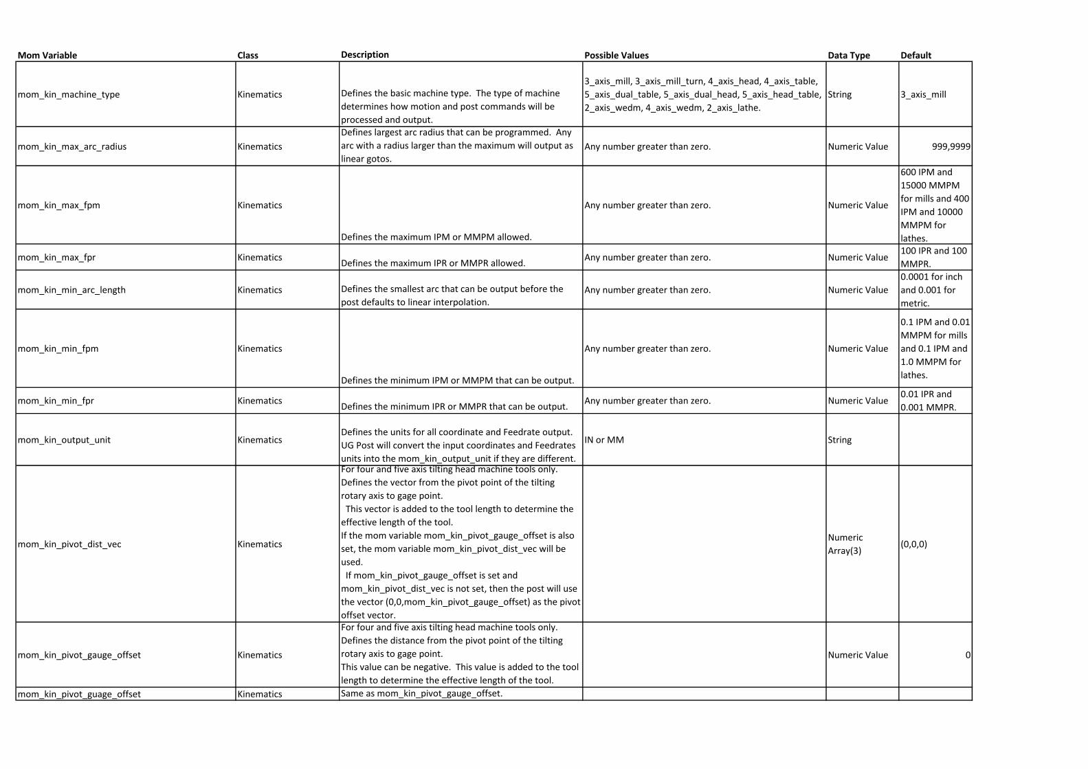
mom_kin_machine_type Kinematics Defines the basic machine type. The type of machine
determines how motion and post commands will be
processed and output.
3_axis_mill, 3_axis_mill_turn, 4_axis_head, 4_axis_table,
5_axis_dual_table, 5_axis_dual_head, 5_axis_head_table,
2_axis_wedm, 4_axis_wedm, 2_axis_lathe.
String 3_axis_mill
mom_kin_max_arc_radius Kinematics
Defines largest arc radius that can be programmed. Any
arc with a radius larger than the maximum will output as
linear gotos.Any number greater than zero. Numeric Value 999,9999
mom_kin_max_fpm Kinematics
Defines the maximum IPM or MMPM allowed.
Any number greater than zero. Numeric Value
600 IPM and
15000 MMPM
for mills and 400
IPM and 10000
MMPM for
lathes.
mom_kin_max_fpr KinematicsDefines the maximum IPR or MMPR allowed.
Any number greater than zero. Numeric Value100 IPR and 100
MMPR.
mom_kin_min_arc_length Kinematics Defines the smallest arc that can be output before the
post defaults to linear interpolation.Any number greater than zero. Numeric Value
0.0001 for inch
and 0.001 for
metric.
mom_kin_min_fpm Kinematics
Defines the minimum IPM or MMPM that can be output.
Any number greater than zero. Numeric Value
0.1 IPM and 0.01
MMPM for mills
and 0.1 IPM and
1.0 MMPM for
lathes.
mom_kin_min_fpr KinematicsDefines the minimum IPR or MMPR that can be output.
Any number greater than zero. Numeric Value0.01 IPR and
0.001 MMPR.
mom_kin_output_unit KinematicsDefines the units for all coordinate and Feedrate output.
UG Post will convert the input coordinates and Feedrates
units into the mom_kin_output_unit if they are different.
IN or MM String
mom_kin_pivot_dist_vec Kinematics
For four and five axis tilting head machine tools only.
Defines the vector from the pivot point of the tilting
rotary axis to gage point.
This vector is added to the tool length to determine the
effective length of the tool.
If the mom variable mom_kin_pivot_gauge_offset is also
set, the mom variable mom_kin_pivot_dist_vec will be
used.
If mom_kin_pivot_gauge_offset is set and
mom_kin_pivot_dist_vec is not set, then the post will use
the vector (0,0,mom_kin_pivot_gauge_offset) as the pivot
offset vector.
Numeric
Array(3)(0,0,0)
mom_kin_pivot_gauge_offset Kinematics
For four and five axis tilting head machine tools only.
Defines the distance from the pivot point of the tilting
rotary axis to gage point.
This value can be negative. This value is added to the tool
length to determine the effective length of the tool.
Numeric Value 0
mom_kin_pivot_guage_offset Kinematics Same as mom_kin_pivot_gauge_offset.
Mom Variable Class Description Possible Values Data Type Default
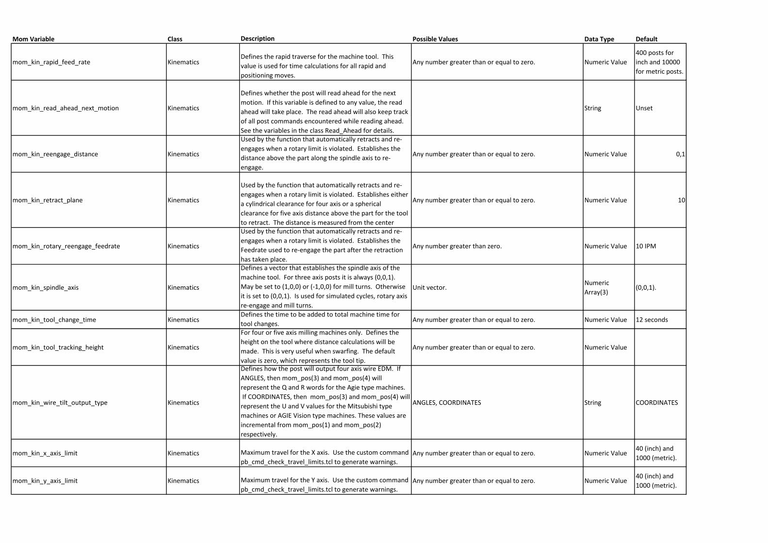
mom_kin_rapid_feed_rate KinematicsDefines the rapid traverse for the machine tool. This
value is used for time calculations for all rapid and
positioning moves.
Any number greater than or equal to zero. Numeric Value
400 posts for
inch and 10000
for metric posts.
mom_kin_read_ahead_next_motion Kinematics
Defines whether the post will read ahead for the next
motion. If this variable is defined to any value, the read
ahead will take place. The read ahead will also keep track
of all post commands encountered while reading ahead.
See the variables in the class Read_Ahead for details.
String Unset
mom_kin_reengage_distance Kinematics
Used by the function that automatically retracts and re-
engages when a rotary limit is violated. Establishes the
distance above the part along the spindle axis to re-
engage.
Any number greater than or equal to zero. Numeric Value 0,1
mom_kin_retract_plane Kinematics
Used by the function that automatically retracts and re-
engages when a rotary limit is violated. Establishes either
a cylindrical clearance for four axis or a spherical
clearance for five axis distance above the part for the tool
to retract. The distance is measured from the center
Any number greater than or equal to zero. Numeric Value 10
mom_kin_rotary_reengage_feedrate Kinematics
Used by the function that automatically retracts and re-
engages when a rotary limit is violated. Establishes the
Feedrate used to re-engage the part after the retraction
has taken place.
Any number greater than zero. Numeric Value 10 IPM
mom_kin_spindle_axis Kinematics
Defines a vector that establishes the spindle axis of the
machine tool. For three axis posts it is always (0,0,1).
May be set to (1,0,0) or (-1,0,0) for mill turns. Otherwise
it is set to (0,0,1). Is used for simulated cycles, rotary axis
re-engage and mill turns.
Unit vector.Numeric
Array(3)(0,0,1).
mom_kin_tool_change_time KinematicsDefines the time to be added to total machine time for
tool changes.Any number greater than or equal to zero. Numeric Value 12 seconds
mom_kin_tool_tracking_height Kinematics
For four or five axis milling machines only. Defines the
height on the tool where distance calculations will be
made. This is very useful when swarfing. The default
value is zero, which represents the tool tip.
Any number greater than or equal to zero. Numeric Value
mom_kin_wire_tilt_output_type Kinematics
Defines how the post will output four axis wire EDM. If
ANGLES, then mom_pos(3) and mom_pos(4) will
represent the Q and R words for the Agie type machines.
If COORDINATES, then mom_pos(3) and mom_pos(4) will
represent the U and V values for the Mitsubishi type
machines or AGIE Vision type machines. These values are
incremental from mom_pos(1) and mom_pos(2)
respectively.
ANGLES, COORDINATES String COORDINATES
mom_kin_x_axis_limit Kinematics Maximum travel for the X axis. Use the custom command
pb_cmd_check_travel_limits.tcl to generate warnings.Any number greater than or equal to zero. Numeric Value
40 (inch) and
1000 (metric).
mom_kin_y_axis_limit Kinematics Maximum travel for the Y axis. Use the custom command
pb_cmd_check_travel_limits.tcl to generate warnings.Any number greater than or equal to zero. Numeric Value
40 (inch) and
1000 (metric).
Mom Variable Class Description Possible Values Data Type Default
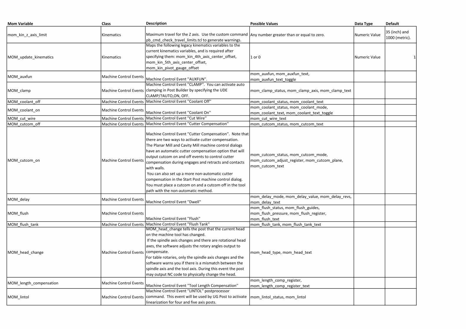
mom_kin_z_axis_limit Kinematics Maximum travel for the Z axis. Use the custom command
pb_cmd_check_travel_limits.tcl to generate warnings.Any number greater than or equal to zero. Numeric Value
35 (inch) and
1000 (metric).
MOM_update_kinematics Kinematics
Maps the following legacy kinematics variables to the
current kinematics variables, and is required after
specifying them: mom_kin_4th_axis_center_offset,
mom_kin_5th_axis_center_offset,
mom_kin_pivot_gauge_offset
1 or 0 Numeric Value 1
MOM_auxfun Machine Control EventsMachine Control Event ''AUXFUN''.
mom_auxfun, mom_auxfun_text,
mom_auxfun_text_toggle
MOM_clamp Machine Control Events
Machine Control Event ''CLAMP''. You can activate auto
clamping in Post Builder by specifying the UDE
CLAMP/?AUTO,ON, OFF. mom_clamp_status, mom_clamp_axis, mom_clamp_text
MOM_coolant_off Machine Control Events Machine Control Event ''Coolant Off'' mom_coolant_status, mom_coolant_text
MOM_coolant_on Machine Control EventsMachine Control Event ''Coolant On''
mom_coolant_status, mom_coolant_mode,
mom_coolant_text, mom_coolant_text_toggle
MOM_cut_wire Machine Control Events Machine Control Event ''Cut Wire'' mom_cut_wire_text
MOM_cutcom_off Machine Control Events Machine Control Event ''Cutter Compensation'' mom_cutcom_status, mom_cutcom_text
MOM_cutcom_on Machine Control Events
Machine Control Event ''Cutter Compensation''. Note that
there are two ways to activate cutter compensation.
The Planar Mill and Cavity Mill machine control dialogs
have an automatic cutter compensation option that will
output cutcom on and off events to control cutter
compensation during engages and retracts and contacts
with walls.
You can also set up a more non-automatic cutter
compensation in the Start Post machine control dialog.
You must place a cutcom on and a cutcom off in the tool
path with the non-automatic method.
mom_cutcom_status, mom_cutcom_mode,
mom_cutcom_adjust_register, mom_cutcom_plane,
mom_cutcom_text
MOM_delay Machine Control EventsMachine Control Event ''Dwell''
mom_delay_mode, mom_delay_value, mom_delay_revs,
mom_delay_text
MOM_flush Machine Control EventsMachine Control Event ''Flush''
mom_flush_status, mom_flush_guides,
mom_flush_pressure, mom_flush_register,
mom_flush_text
MOM_flush_tank Machine Control Events Machine Control Event ''Flush Tank'' mom_flush_tank, mom_flush_tank_text
MOM_head_change Machine Control Events
MOM_head_change tells the post that the current head
on the machine tool has changed.
If the spindle axis changes and there are rotational head
axes, the software adjusts the rotary angles output to
compensate.
For table rotaries, only the spindle axis changes and the
software warns you if there is a mismatch between the
spindle axis and the tool axis. During this event the post
may output NC code to physically change the head.
mom_head_type, mom_head_text
MOM_length_compensation Machine Control EventsMachine Control Event ''Tool Length Compensation''
mom_length_comp_register,
mom_length_comp_register_text
MOM_lintol Machine Control Events
Machine Control Event ''LINTOL'' postprocessor
command. This event will be used by UG Post to activate
linearization for four and five axis posts.mom_lintol_status, mom_lintol
Mom Variable Class Description Possible Values Data Type Default
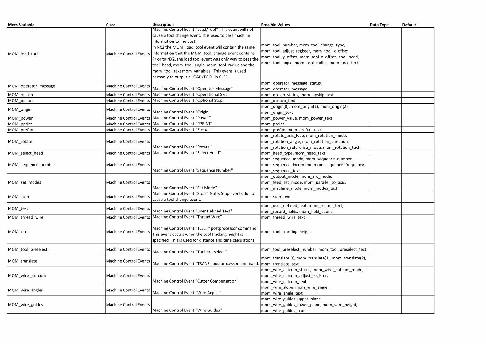
MOM_load_tool Machine Control Events
Machine Control Event ''Load/Tool'' This event will not
cause a tool change event. It is used to pass machine
information to the post.
In NX2 the MOM_load_tool event will contain the same
information that the MOM_tool_change event contains.
Prior to NX2, the load tool event was only way to pass the
tool_head, mom_tool_angle, mom_tool_radius and the
mom_tool_text mom_variables. This event is used
primarily to output a LOAD/TOOL in CLSF.
mom_tool_number, mom_tool_change_type,
mom_tool_adjust_register, mom_tool_x_offset,
mom_tool_y_offset, mom_tool_z_offset, tool_head,
mom_tool_angle, mom_tool_radius, mom_tool_text
MOM_operator_message Machine Control EventsMachine Control Event ''Operator Message''.
mom_operator_message_status,
mom_operator_message
MOM_opskip Machine Control Events Machine Control Event ''Operational Skip'' mom_opskip_status, mom_opskip_text
MOM_opstop Machine Control Events Machine Control Event ''Optional Stop'' mom_opstop_text
MOM_origin Machine Control EventsMachine Control Event ''Origin''
mom_origin(0), mom_origin(1), mom_origin(2),
mom_origin_text
MOM_power Machine Control Events Machine Control Event ''Power'' mom_power_value, mom_power_text
MOM_pprint Machine Control Events Machine Control Event ''PPRINT'' mom_pprint
MOM_prefun Machine Control Events Machine Control Event ''Prefun'' mom_prefun, mom_prefun_text
MOM_rotate Machine Control EventsMachine Control Event ''Rotate''
mom_rotate_axis_type, mom_rotation_mode,
mom_rotation_angle, mom_rotation_direction,
mom_rotation_reference_mode, mom_rotation_text
MOM_select_head Machine Control Events Machine Control Event ''Select Head'' mom_head_type, mom_head_text
MOM_sequence_number Machine Control EventsMachine Control Event ''Sequence Number''
mom_sequence_mode, mom_sequence_number,
mom_sequence_increment, mom_sequence_frequency,
mom_sequence_text
MOM_set_modes Machine Control EventsMachine Control Event ''Set Mode''
mom_output_mode, mom_arc_mode,
mom_feed_set_mode, mom_parallel_to_axis,
mom_machine_mode, mom_modes_text
MOM_stop Machine Control EventsMachine Control Event ''Stop'' Note: Stop events do not
cause a tool change event.mom_stop_text
MOM_text Machine Control EventsMachine Control Event ''User Defined Text''
mom_user_defined_text, mom_record_text,
mom_record_fields, mom_field_count
MOM_thread_wire Machine Control Events Machine Control Event ''Thread Wire'' mom_thread_wire_text
MOM_tlset Machine Control EventsMachine Control Event ''TLSET'' postprocessor command.
This event occurs when the tool tracking height is
specified. This is used for distance and time calculations.
mom_tool_tracking_height
MOM_tool_preselect Machine Control EventsMachine Control Event ''Tool pre-select''
mom_tool_preselect_number, mom_tool_preselect_text
MOM_translate Machine Control EventsMachine Control Event ''TRANS'' postprocessor command.
mom_translate(0), mom_translate(1), mom_translate(2),
mom_translate_text
MOM_wire _cutcom Machine Control EventsMachine Control Event ''Cutter Compensation''
mom_wire_cutcom_status, mom_wire _cutcom_mode,
mom_wire_cutcom_adjust_register,
mom_wire_cutcom_text
MOM_wire_angles Machine Control EventsMachine Control Event ''Wire Angles''
mom_wire_slope, mom_wire_angle,
mom_wire_angle_text
MOM_wire_guides Machine Control EventsMachine Control Event ''Wire Guides''
mom_wire_guides_upper_plane,
mom_wire_guides_lower_plane, mom_wire_height,
mom_wire_guides_text
Mom Variable Class Description Possible Values Data Type Default
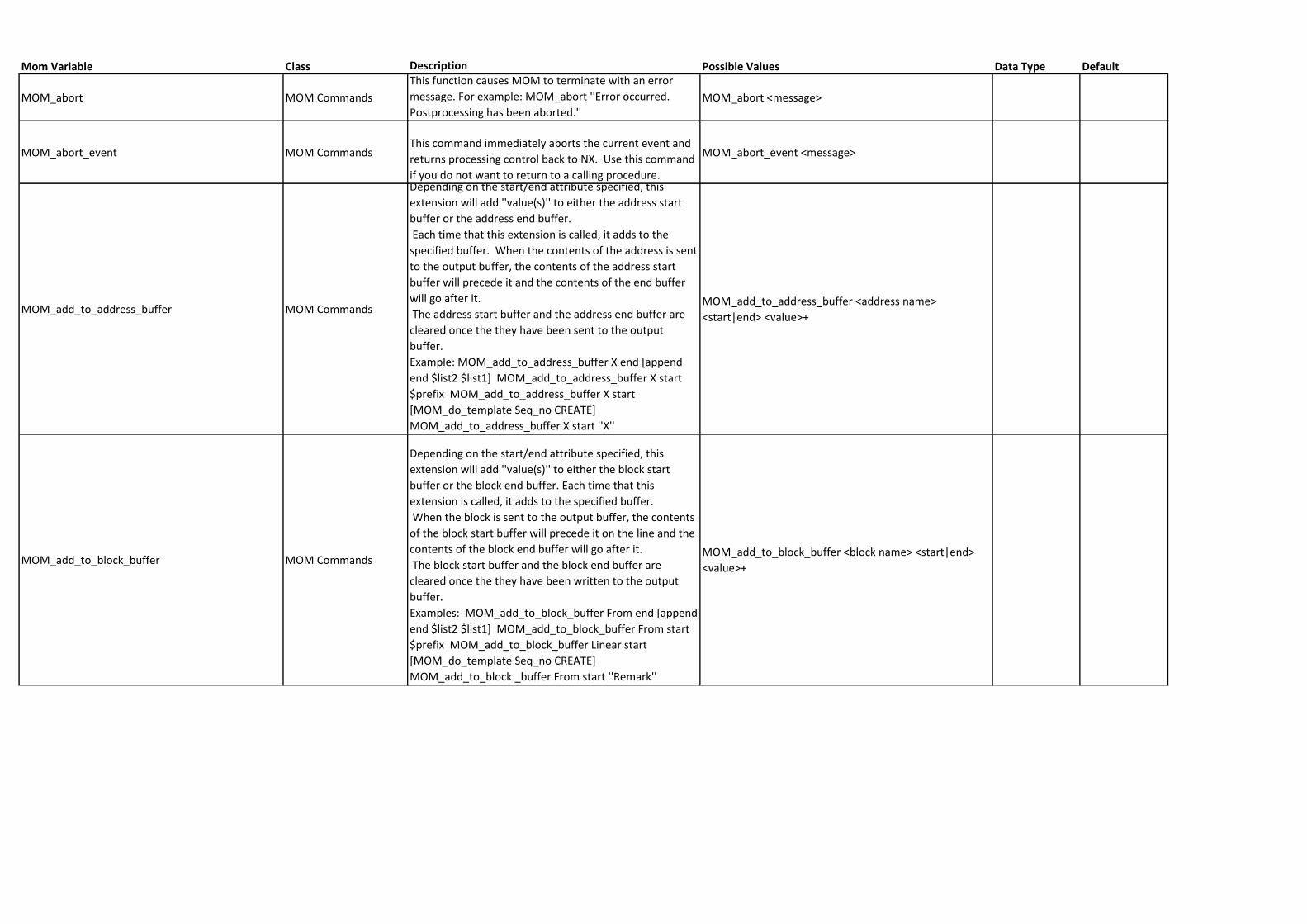
MOM_abort MOM Commands
This function causes MOM to terminate with an error
message. For example: MOM_abort ''Error occurred.
Postprocessing has been aborted.''MOM_abort <message>
MOM_abort_event MOM CommandsThis command immediately aborts the current event and
returns processing control back to NX. Use this command
if you do not want to return to a calling procedure.
MOM_abort_event <message>
MOM_add_to_address_buffer MOM Commands
Depending on the start/end attribute specified, this
extension will add ''value(s)'' to either the address start
buffer or the address end buffer.
Each time that this extension is called, it adds to the
specified buffer. When the contents of the address is sent
to the output buffer, the contents of the address start
buffer will precede it and the contents of the end buffer
will go after it.
The address start buffer and the address end buffer are
cleared once the they have been sent to the output
buffer.
Example: MOM_add_to_address_buffer X end [append
end $list2 $list1] MOM_add_to_address_buffer X start
$prefix MOM_add_to_address_buffer X start
[MOM_do_template Seq_no CREATE]
MOM_add_to_address_buffer X start ''X''
MOM_add_to_address_buffer <address name>
<start|end> <value>+
MOM_add_to_block_buffer MOM Commands
Depending on the start/end attribute specified, this
extension will add ''value(s)'' to either the block start
buffer or the block end buffer. Each time that this
extension is called, it adds to the specified buffer.
When the block is sent to the output buffer, the contents
of the block start buffer will precede it on the line and the
contents of the block end buffer will go after it.
The block start buffer and the block end buffer are
cleared once the they have been written to the output
buffer.
Examples: MOM_add_to_block_buffer From end [append
end $list2 $list1] MOM_add_to_block_buffer From start
$prefix MOM_add_to_block_buffer Linear start
[MOM_do_template Seq_no CREATE]
MOM_add_to_block _buffer From start ''Remark''
MOM_add_to_block_buffer <block name> <start|end>
<value>+
Mom Variable Class Description Possible Values Data Type Default
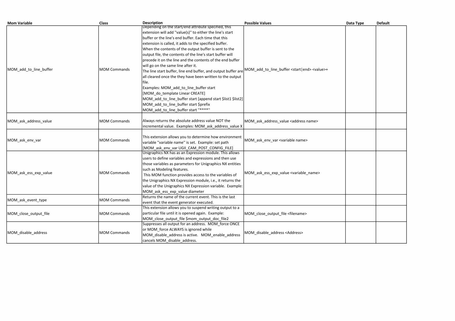
MOM_add_to_line_buffer MOM Commands
Depending on the start/end attribute specified, this
extension will add ''value(s)'' to either the line's start
buffer or the line's end buffer. Each time that this
extension is called, it adds to the specified buffer.
When the contents of the output buffer is sent to the
output file, the contents of the line's start buffer will
precede it on the line and the contents of the end buffer
will go on the same line after it.
The line start buffer, line end buffer, and output buffer are
all cleared once the they have been written to the output
file.
Examples: MOM_add_to_line_buffer start
[MOM_do_template Linear CREATE]
MOM_add_to_line_buffer start [append start $list1 $list2]
MOM_add_to_line_buffer start $prefix
MOM_add_to_line_buffer start ''****''
MOM_add_to_line_buffer <start|end> <value>+
MOM_ask_address_value MOM Commands Always returns the absolute address value NOT the
incremental value. Examples: MOM_ask_address_value XMOM_ask_address_value <address name>
MOM_ask_env_var MOM CommandsThis extension allows you to determine how environment
variable ''variable name'' is set. Example: set path
[MOM_ask_env_var UGII_CAM_POST_CONFIG_FILE]
MOM_ask_env_var <variable name>
MOM_ask_ess_exp_value MOM Commands
Unigraphics NX has as an Expression module. This allows
users to define variables and expressions and then use
those variables as parameters for Unigraphics NX entities
such as Modeling features.
This MOM function provides access to the variables of
the Unigraphics NX Expression module, i.e., it returns the
value of the Unigraphics NX Expression variable. Example:
MOM_ask_ess_exp_value diameter
MOM_ask_ess_exp_value <variable_name>
MOM_ask_event_type MOM CommandsReturns the name of the current event. This is the last
event that the event generator executed.
MOM_close_output_file MOM Commands
This extension allows you to suspend writing output to a
particular file until it is opened again. Example:
MOM_close_output_file $mom_output_doc_file2MOM_close_output_file <filename>
MOM_disable_address MOM Commands
Suppresses all output for an address. MOM_force ONCE
or MOM_force ALWAYS is ignored while
MOM_disable_address is active. MOM_enable_address
cancels MOM_disable_address.
MOM_disable_address <Address>
Mom Variable Class Description Possible Values Data Type Default
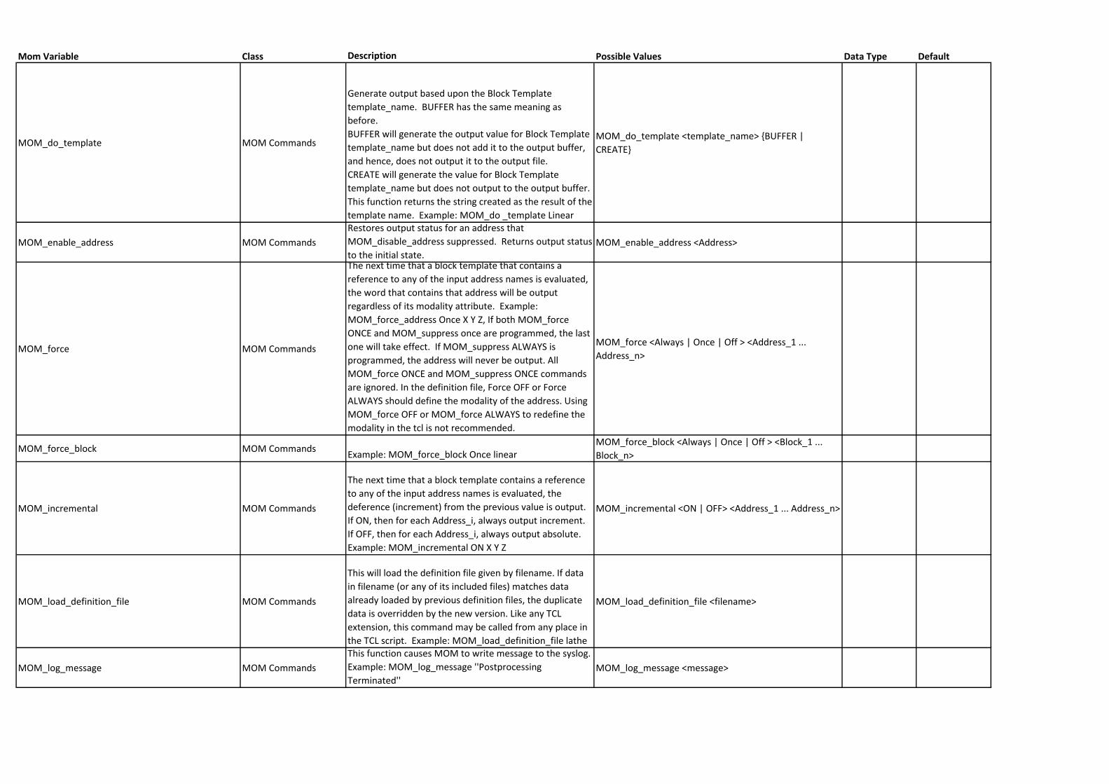
MOM_do_template MOM Commands
Generate output based upon the Block Template
template_name. BUFFER has the same meaning as
before.
BUFFER will generate the output value for Block Template
template_name but does not add it to the output buffer,
and hence, does not output it to the output file.
CREATE will generate the value for Block Template
template_name but does not output to the output buffer.
This function returns the string created as the result of the
template name. Example: MOM_do _template Linear
MOM_do_template <template_name> {BUFFER |
CREATE}
MOM_enable_address MOM Commands
Restores output status for an address that
MOM_disable_address suppressed. Returns output status
to the initial state.MOM_enable_address <Address>
MOM_force MOM Commands
The next time that a block template that contains a
reference to any of the input address names is evaluated,
the word that contains that address will be output
regardless of its modality attribute. Example:
MOM_force_address Once X Y Z, If both MOM_force
ONCE and MOM_suppress once are programmed, the last
one will take effect. If MOM_suppress ALWAYS is
programmed, the address will never be output. All
MOM_force ONCE and MOM_suppress ONCE commands
are ignored. In the definition file, Force OFF or Force
ALWAYS should define the modality of the address. Using
MOM_force OFF or MOM_force ALWAYS to redefine the
modality in the tcl is not recommended.
MOM_force <Always | Once | Off > <Address_1 ...
Address_n>
MOM_force_block MOM CommandsExample: MOM_force_block Once linear
MOM_force_block <Always | Once | Off > <Block_1 ...
Block_n>
MOM_incremental MOM Commands
The next time that a block template contains a reference
to any of the input address names is evaluated, the
deference (increment) from the previous value is output.
If ON, then for each Address_i, always output increment.
If OFF, then for each Address_i, always output absolute.
Example: MOM_incremental ON X Y Z
MOM_incremental <ON | OFF> <Address_1 ... Address_n>
MOM_load_definition_file MOM Commands
This will load the definition file given by filename. If data
in filename (or any of its included files) matches data
already loaded by previous definition files, the duplicate
data is overridden by the new version. Like any TCL
extension, this command may be called from any place in
the TCL script. Example: MOM_load_definition_file lathe
MOM_load_definition_file <filename>
MOM_log_message MOM Commands
This function causes MOM to write message to the syslog.
Example: MOM_log_message ''Postprocessing
Terminated''MOM_log_message <message>
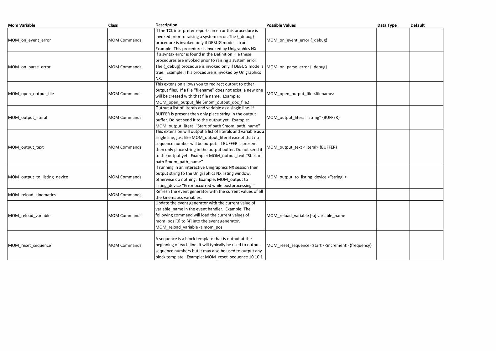
Mom Variable Class Description Possible Values Data Type Default
MOM_on_event_error MOM Commands
If the TCL interpreter reports an error this procedure is
invoked prior to raising a system error. The {_debug}
procedure is invoked only if DEBUG mode is true.
Example: This procedure is invoked by Unigraphics NX
MOM_on_event_error {_debug}
MOM_on_parse_error MOM Commands
If a syntax error is found in the Definition File these
procedures are invoked prior to raising a system error.
The {_debug} procedure is invoked only if DEBUG mode is
true. Example: This procedure is invoked by Unigraphics
NX.
MOM_on_parse_error {_debug}
MOM_open_output_file MOM Commands
This extension allows you to redirect output to other
output files. If a file ''filename'' does not exist, a new one
will be created with that file name. Example:
MOM_open_output_file $mom_output_doc_file2
MOM_open_output_file <filename>
MOM_output_literal MOM Commands
Output a list of literals and variable as a single line. If
BUFFER is present then only place string in the output
buffer. Do not send it to the output yet. Example:
MOM_output_literal ''Start of path $mom_path_name''
MOM_output_literal ''string'' {BUFFER}
MOM_output_text MOM Commands
This extension will output a list of literals and variable as a
single line, just like MOM_output_literal except that no
sequence number will be output. If BUFFER is present
then only place string in the output buffer. Do not send it
to the output yet. Example: MOM_output_text ''Start of
path $mom_path_name''
MOM_output_text <literal> {BUFFER}
MOM_output_to_listing_device MOM Commands
If running in an interactive Unigraphics NX session then
output string to the Unigraphics NX listing window,
otherwise do nothing. Example: MOM_output to
listing_device ''Error occurred while postprocessing.''
MOM_output_to_listing_device <''string''>
MOM_reload_kinematics MOM CommandsRefresh the event generator with the current values of all
the kinematics variables.
MOM_reload_variable MOM Commands
Update the event generator with the current value of
variable_name in the event handler. Example: The
following command will load the current values of
mom_pos [0] to [4] into the event generator.
MOM_reload_variable -a mom_pos
MOM_reload_variable [-a] variable_name
MOM_reset_sequence MOM Commands
A sequence is a block template that is output at the
beginning of each line. It will typically be used to output
sequence numbers but it may also be used to output any
block template. Example: MOM_reset_sequence 10 10 1
MOM_reset_sequence <start> <increment> {frequency}
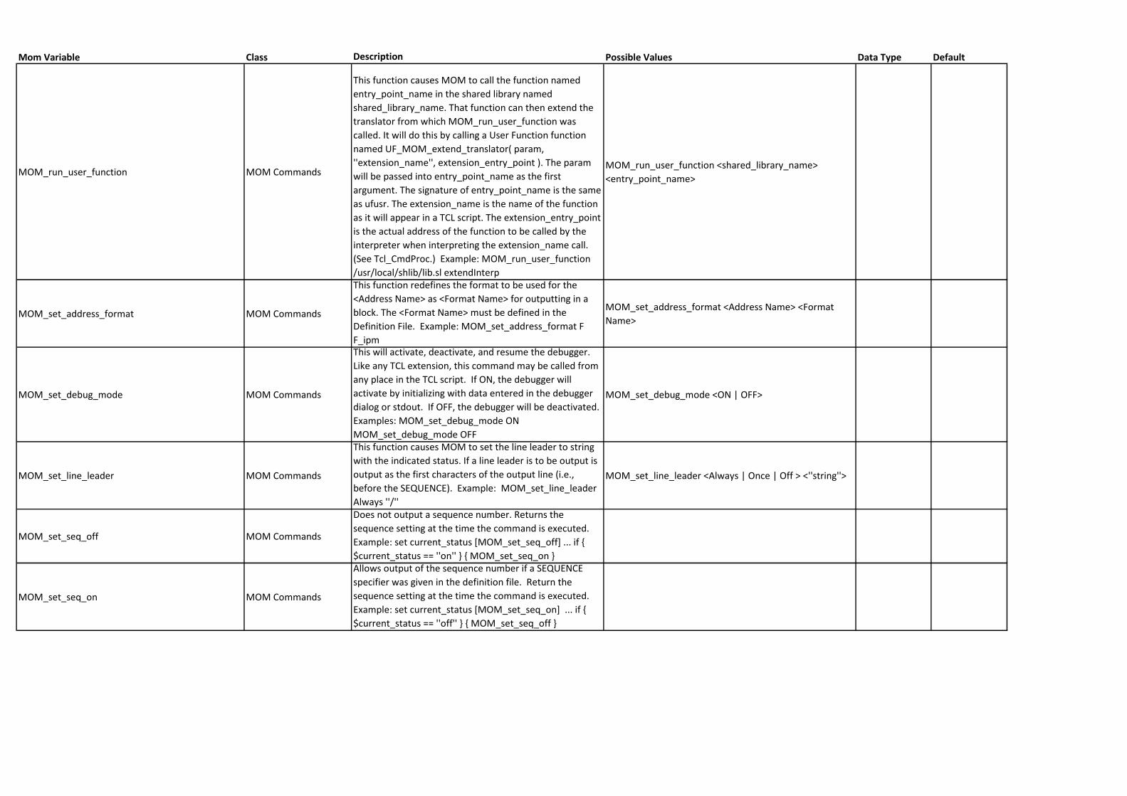
Mom Variable Class Description Possible Values Data Type Default
MOM_run_user_function MOM Commands
This function causes MOM to call the function named
entry_point_name in the shared library named
shared_library_name. That function can then extend the
translator from which MOM_run_user_function was
called. It will do this by calling a User Function function
named UF_MOM_extend_translator( param,
''extension_name'', extension_entry_point ). The param
will be passed into entry_point_name as the first
argument. The signature of entry_point_name is the same
as ufusr. The extension_name is the name of the function
as it will appear in a TCL script. The extension_entry_point
is the actual address of the function to be called by the
interpreter when interpreting the extension_name call.
(See Tcl_CmdProc.) Example: MOM_run_user_function
/usr/local/shlib/lib.sl extendInterp
MOM_run_user_function <shared_library_name>
<entry_point_name>
MOM_set_address_format MOM Commands
This function redefines the format to be used for the
<Address Name> as <Format Name> for outputting in a
block. The <Format Name> must be defined in the
Definition File. Example: MOM_set_address_format F
F_ipm
MOM_set_address_format <Address Name> <Format
Name>
MOM_set_debug_mode MOM Commands
This will activate, deactivate, and resume the debugger.
Like any TCL extension, this command may be called from
any place in the TCL script. If ON, the debugger will
activate by initializing with data entered in the debugger
dialog or stdout. If OFF, the debugger will be deactivated.
Examples: MOM_set_debug_mode ON
MOM_set_debug_mode OFF
MOM_set_debug_mode <ON | OFF>
MOM_set_line_leader MOM Commands
This function causes MOM to set the line leader to string
with the indicated status. If a line leader is to be output is
output as the first characters of the output line (i.e.,
before the SEQUENCE). Example: MOM_set_line_leader
Always ''/''
MOM_set_line_leader <Always | Once | Off > <''string''>
MOM_set_seq_off MOM Commands
Does not output a sequence number. Returns the
sequence setting at the time the command is executed.
Example: set current_status [MOM_set_seq_off] ... if {
$current_status == ''on'' } { MOM_set_seq_on }
MOM_set_seq_on MOM Commands
Allows output of the sequence number if a SEQUENCE
specifier was given in the definition file. Return the
sequence setting at the time the command is executed.
Example: set current_status [MOM_set_seq_on] ... if {
$current_status == ''off'' } { MOM_set_seq_off }
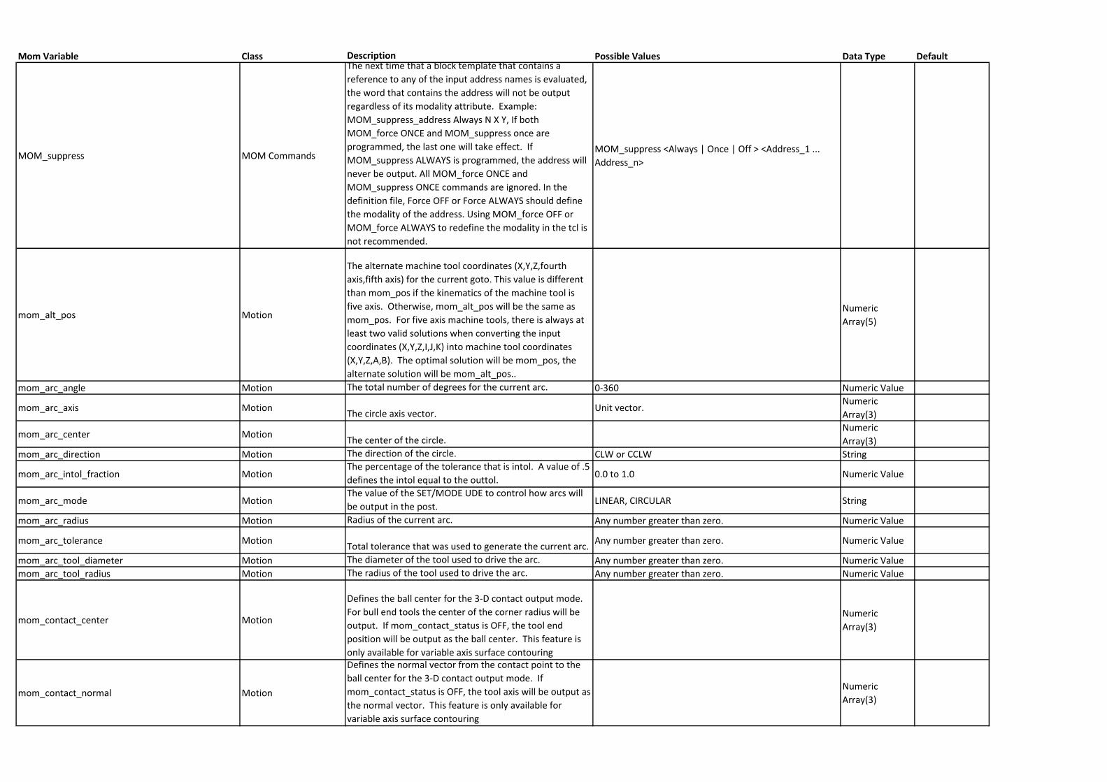
Mom Variable Class Description Possible Values Data Type Default
MOM_suppress MOM Commands
The next time that a block template that contains a
reference to any of the input address names is evaluated,
the word that contains the address will not be output
regardless of its modality attribute. Example:
MOM_suppress_address Always N X Y, If both
MOM_force ONCE and MOM_suppress once are
programmed, the last one will take effect. If
MOM_suppress ALWAYS is programmed, the address will
never be output. All MOM_force ONCE and
MOM_suppress ONCE commands are ignored. In the
definition file, Force OFF or Force ALWAYS should define
the modality of the address. Using MOM_force OFF or
MOM_force ALWAYS to redefine the modality in the tcl is
not recommended.
MOM_suppress <Always | Once | Off > <Address_1 ...
Address_n>
mom_alt_pos Motion
The alternate machine tool coordinates (X,Y,Z,fourth
axis,fifth axis) for the current goto. This value is different
than mom_pos if the kinematics of the machine tool is
five axis. Otherwise, mom_alt_pos will be the same as
mom_pos. For five axis machine tools, there is always at
least two valid solutions when converting the input
coordinates (X,Y,Z,I,J,K) into machine tool coordinates
(X,Y,Z,A,B). The optimal solution will be mom_pos, the
alternate solution will be mom_alt_pos..
Numeric
Array(5)
mom_arc_angle Motion The total number of degrees for the current arc. 0-360 Numeric Value
mom_arc_axis MotionThe circle axis vector.
Unit vector.Numeric
Array(3)
mom_arc_center MotionThe center of the circle.
Numeric
Array(3)
mom_arc_direction Motion The direction of the circle. CLW or CCLW String
mom_arc_intol_fraction MotionThe percentage of the tolerance that is intol. A value of .5
defines the intol equal to the outtol.0.0 to 1.0 Numeric Value
mom_arc_mode MotionThe value of the SET/MODE UDE to control how arcs will
be output in the post.LINEAR, CIRCULAR String
mom_arc_radius Motion Radius of the current arc. Any number greater than zero. Numeric Value
mom_arc_tolerance MotionTotal tolerance that was used to generate the current arc.
Any number greater than zero. Numeric Value
mom_arc_tool_diameter Motion The diameter of the tool used to drive the arc. Any number greater than zero. Numeric Value
mom_arc_tool_radius Motion The radius of the tool used to drive the arc. Any number greater than zero. Numeric Value
mom_contact_center Motion
Defines the ball center for the 3-D contact output mode.
For bull end tools the center of the corner radius will be
output. If mom_contact_status is OFF, the tool end
position will be output as the ball center. This feature is
only available for variable axis surface contouring
Numeric
Array(3)
mom_contact_normal Motion
Defines the normal vector from the contact point to the
ball center for the 3-D contact output mode. If
mom_contact_status is OFF, the tool axis will be output as
the normal vector. This feature is only available for
variable axis surface contouring
Numeric
Array(3)
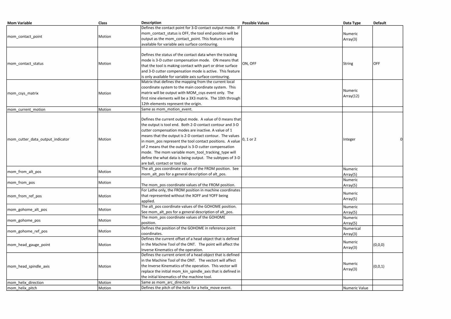
Mom Variable Class Description Possible Values Data Type Default
mom_contact_point Motion
Defines the contact point for 3-D contact output mode. If
mom_contact_status is OFF, the tool end position will be
output as the mom_contact_point. This feature is only
available for variable axis surface contouring.
Numeric
Array(3)
mom_contact_status Motion
Defines the status of the contact data when the tracking
mode is 3-D cutter compensation mode. ON means that
that the tool is making contact with part or drive surface
and 3-D cutter compensation mode is active. This feature
is only available for variable axis surface contouring.
ON, OFF String OFF
mom_csys_matrix Motion
Matrix that defines the mapping from the current local
coordinate system to the main coordinate system. This
matrix will be output with MOM_csys event only. The
first nine elements will be a 3X3 matrix. The 10th through
12th elements represent the origin.
Numeric
Array(12)
mom_current_motion Motion Same as mom_motion_event.
mom_cutter_data_output_indicator Motion
Defines the current output mode. A value of 0 means that
the output is tool end. Both 2-D contact contour and 3-D
cutter compensation modes are inactive. A value of 1
means that the output is 2-D contact contour. The values
in mom_pos represent the tool contact positions. A value
of 2 means that the output is 3-D cutter compensation
mode. The mom variable mom_tool_tracking_type will
define the what data is being output. The subtypes of 3-D
are ball, contact or tool tip.
0, 1 or 2 Integer 0
mom_from_alt_pos MotionThe alt_pos coordinate values of the FROM position. See
mom_alt_pos for a general description of alt_pos.Numeric
Array(5)
mom_from_pos MotionThe mom_pos coordinate values of the FROM position.
Numeric
Array(5)
mom_from_ref_pos Motion
For Lathe only, the FROM position in machine coordinates
that represented without the XOFF and YOFF being
applied.
Numeric
Array(5)
mom_gohome_alt_pos MotionThe alt_pos coordinate values of the GOHOME position.
See mom_alt_pos for a general description of alt_pos.Numeric
Array(5)
mom_gohome_pos MotionThe mom_pos coordinate values of the GOHOME
position.Numeric
Array(5)
mom_gohome_ref_pos MotionDefines the position of the GOHOME in reference point
coordinates.Numerical
Array(3)
mom_head_gauge_point Motion
Defines the current offset of a head object that is defined
in the Machine Tool of the ONT. The point will affect the
Inverse Kinematics of the operation.
Numeric
Array(3)(0,0,0)
mom_head_spindle_axis Motion
Defines the current orient of a head object that is defined
in the Machine Tool of the ONT. The vectort will affect
the Inverse Kinematics of the operation. This vector will
replace the initial mom_kin_spindle_axis that is defined in
the initial kinematics of the machine tool.
Numeric
Array(3)(0,0,1)
mom_helix_direction Motion Same as mom_arc_direction
mom_helix_pitch Motion Defines the pitch of the helix for a helix_move event. Numeric Value
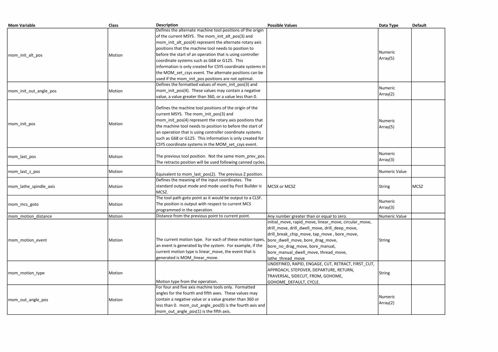
Mom Variable Class Description Possible Values Data Type Default
mom_init_alt_pos Motion
Defines the alternate machine tool positions of the origin
of the current MSYS. The mom_init_alt_pos(3) and
mom_init_alt_pos(4) represent the alternate rotary axis
positions that the machine tool needs to position to
before the start of an operation that is using controller
coordinate systems such as G68 or G125. This
information is only created for CSYS coordinate systems in
the MOM_set_csys event. The alternate positions can be
used if the mom_init_pos positions are not optimal.
Numeric
Array(5)
mom_init_out_angle_pos Motion
Defines the formatted values of mom_init_pos(3) and
mom_init_pos(4). These values may contain a negative
value, a value greater than 360, or a value less than 0.
Numeric
Array(2)
mom_init_pos Motion
Defines the machine tool positions of the origin of the
current MSYS. The mom_init_pos(3) and
mom_init_pos(4) represent the rotary axis positions that
the machine tool needs to position to before the start of
an operation that is using controller coordinate systems
such as G68 or G125. This information is only created for
CSYS coordinate systems in the MOM_set_csys event.
Numeric
Array(5)
mom_last_pos Motion The previous tool position. Not the same mom_prev_pos.
The retracto position will be used following canned cycles.
Numeric
Array(3)
mom_last_z_pos MotionEquivalent to mom_last_pos(2). The previous Z position.
Numeric Value
mom_lathe_spindle_axis Motion
Defines the meaning of the input coordinates. The
standard output mode and mode used by Post Builder is
MCSZ. MCSX or MCSZ String MCSZ
mom_mcs_goto Motion
The tool path goto point as it would be output to a CLSF.
The position is output with respect to current MCS
programmed in the operation.
Numeric
Array(3)
mom_motion_distance Motion Distance from the previous point to current point. Any number greater than or equal to zero. Numeric Value
mom_motion_event Motion The current motion type. For each of these motion types,
an event is generated by the system. For example, if the
current motion type is linear_move, the event that is
generated is MOM_linear_move.
initial_move, rapid_move, linear_move, circular_move,
drill_move, drill_dwell_move, drill_deep_move,
drill_break_chip_move, tap_move , bore_move,
bore_dwell_move, bore_drag_move,
bore_no_drag_move, bore_manual,
bore_manual_dwell_move, thread_move,
lathe_thread_move
String
mom_motion_type Motion
Motion type from the operation.
UNDEFINED, RAPID, ENGAGE, CUT, RETRACT, FIRST_CUT,
APPROACH, STEPOVER, DEPARTURE, RETURN,
TRAVERSAL, SIDECUT, FROM, GOHOME,
GOHOME_DEFAULT, CYCLE.
String
mom_out_angle_pos Motion
For four and five axis machine tools only. Formatted
angles for the fourth and fifth axes. These values may
contain a negative value or a value greater than 360 or
less than 0. mom_out_angle_pos(0) is the fourth axis and
mom_out_angle_pos(1) is the fifth axis.
Numeric
Array(2)
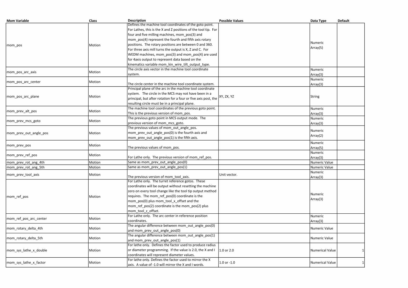
Mom Variable Class Description Possible Values Data Type Default
mom_pos Motion
Defines the machine tool coordinates of the goto point.
For Lathes, this is the X and Z positions of the tool tip. For
four and five milling machines, mom_pos(3) and
mom_pos(4) represent the fourth and fifth axis rotary
positions. The rotary positions are between 0 and 360.
For three axis mill turns the output is X, Z and C. For
WEDM machines, mom_pos(3) and mom_pos(4) are used
for 4axis output to represent data based on the
kinematics variable mom_kin_wire_tilt_output_type.
Numeric
Array(5)
mom_pos_arc_axis MotionThe circle axis vector in the machine tool coordinate
system. Numeric
Array(3)
mom_pos_arc_center MotionThe circle center in the machine tool coordinate system.
Numeric
Array(3)
mom_pos_arc_plane Motion
Principal plane of the arc in the machine tool coordinate
system. The circle in the MCS may not have been in a
principal, but after rotation for a four or five axis post, the
resulting circle must be in a principal plane.
XY, ZX, YZ String
mom_prev_alt_pos MotionThe machine tool coordinates of the previous goto point.
This is the previous version of mom_pos.Numeric
Array(3)
mom_prev_mcs_goto MotionThe previous goto point in MCS output mode. The
previous version of mom_mcs_goto.Numeric
Array(3)
mom_prev_out_angle_pos Motion
The previous values of mom_out_angle_pos.
mom_prev_out_angle_pos(0) is the fourth axis and
mom_prev_out_angle_pos(1) is the fifth axis.
Numeric
Array(2)
mom_prev_pos MotionThe previous values of mom_pos.
Numeric
Array(5)
mom_prev_ref_pos MotionFor Lathe only. The previous version of mom_ref_pos.
Numeric
Array(3)
mom_prev_rot_ang_4th Motion Same as mom_prev_out_angle_pos(0) Numeric Value
mom_prev_rot_ang_5th Motion Same as mom_prev_out_angle_pos(1) Numeric Value
mom_prev_tool_axis MotionThe previous version of mom_tool_axis.
Unit vector.Numeric
Array(3)
mom_ref_pos Motion
For Lathe only. The turret reference gotos. These
coordinates will be output without resetting the machine
zero on every tool change like the tool tip output method
requires. The mom_ref_pos(0) coordinate is the
mom_pos(0) plus mom_tool_x_offset and the
mom_ref_pos(2) coordinate is the mom_pos(2) plus
mom_tool_z_offset.
Numeric
Array(3)
mom_ref_pos_arc_center MotionFor Lathe only. The arc center in reference position
coordinates.Numeric
Array(3)
mom_rotary_delta_4th MotionThe angular difference between mom_out_angle_pos(0)
and mom_prev_out_angle_pos(0)Numeric Value
mom_rotary_delta_5th MotionThe angular difference between mom_out_angle_pos(1)
and mom_prev_out_angle_pos(1)Numeric Value
mom_sys_lathe_x_double Motion
For lathe only. Defines the factor used to produce radius
or diameter programming. If the value is 2.0, the X and I
coordinates will represent diameter values.1.0 or 2.0 Numerical Value 1
mom_sys_lathe_x_factor MotionFor lathe only. Defines the factor used to mirror the X
axis. A value of -1.0 will mirror the X and I words.1.0 or -1.0 Numerical Value 1
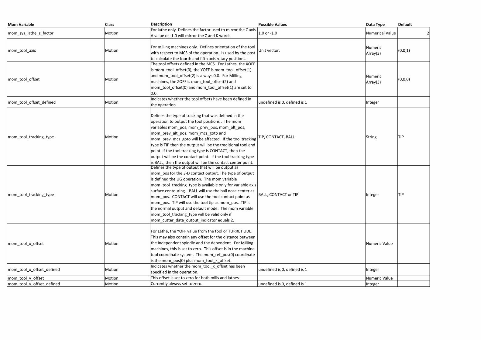
Mom Variable Class Description Possible Values Data Type Default
mom_sys_lathe_z_factor MotionFor lathe only. Defines the factor used to mirror the Z axis.
A value of -1.0 will mirror the Z and K words.1.0 or -1.0 Numerical Value 2
mom_tool_axis MotionFor milling machines only. Defines orientation of the tool
with respect to MCS of the operation. Is used by the post
to calculate the fourth and fifth axis rotary positions.
Unit vector.Numeric
Array(3)(0,0,1)
mom_tool_offset Motion
The tool offsets defined in the MCS. For Lathes, the XOFF
is mom_tool_offset(0), the YOFF is mom_tool_offset(1)
and mom_tool_offset(2) is always 0.0. For Milling
machines, the ZOFF is mom_tool_offset(2) and
mom_tool_offset(0) and mom_tool_offset(1) are set to
0.0.
Numeric
Array(3)(0,0,0)
mom_tool_offset_defined MotionIndicates whether the tool offsets have been defined in
the operation.undefined is 0, defined is 1 Integer
mom_tool_tracking_type Motion
Defines the type of tracking that was defined in the
operation to output the tool positions . The mom
variables mom_pos, mom_prev_pos, mom_alt_pos,
mom_prev_alt_pos, mom_mcs_goto and
mom_prev_mcs_goto will be affected. If the tool tracking
type is TIP then the output will be the traditional tool end
point. If the tool tracking type is CONTACT, then the
output will be the contact point. If the tool tracking type
is BALL, then the output will be the contact center point.
TIP, CONTACT, BALL String TIP
mom_tool_tracking_type Motion
Defines the type of output that will be output as
mom_pos for the 3-D contact output. The type of output
is defined the UG operation. The mom variable
mom_tool_tracking_type is available only for variable axis
surface contouring. BALL will use the ball nose center as
mom_pos. CONTACT will use the tool contact point as
mom_pos. TIP will use the tool tip as mom_pos. TIP is
the normal output and default mode. The mom variable
mom_tool_tracking_type will be valid only if
mom_cutter_data_output_indicator equals 2.
BALL, CONTACT or TIP Integer TIP
mom_tool_x_offset Motion
For Lathe, the YOFF value from the tool or TURRET UDE.
This may also contain any offset for the distance between
the independent spindle and the dependent. For Milling
machines, this is set to zero. This offset is in the machine
tool coordinate system. The mom_ref_pos(0) coordinate
is the mom_pos(0) plus mom_tool_x_offset.
Numeric Value
mom_tool_x_offset_defined MotionIndicates whether the mom_tool_x_offset has been
specified in the operation.undefined is 0, defined is 1 Integer
mom_tool_y_offset Motion This offset is set to zero for both mills and lathes. Numeric Value
mom_tool_y_offset_defined Motion Currently always set to zero. undefined is 0, defined is 1 Integer
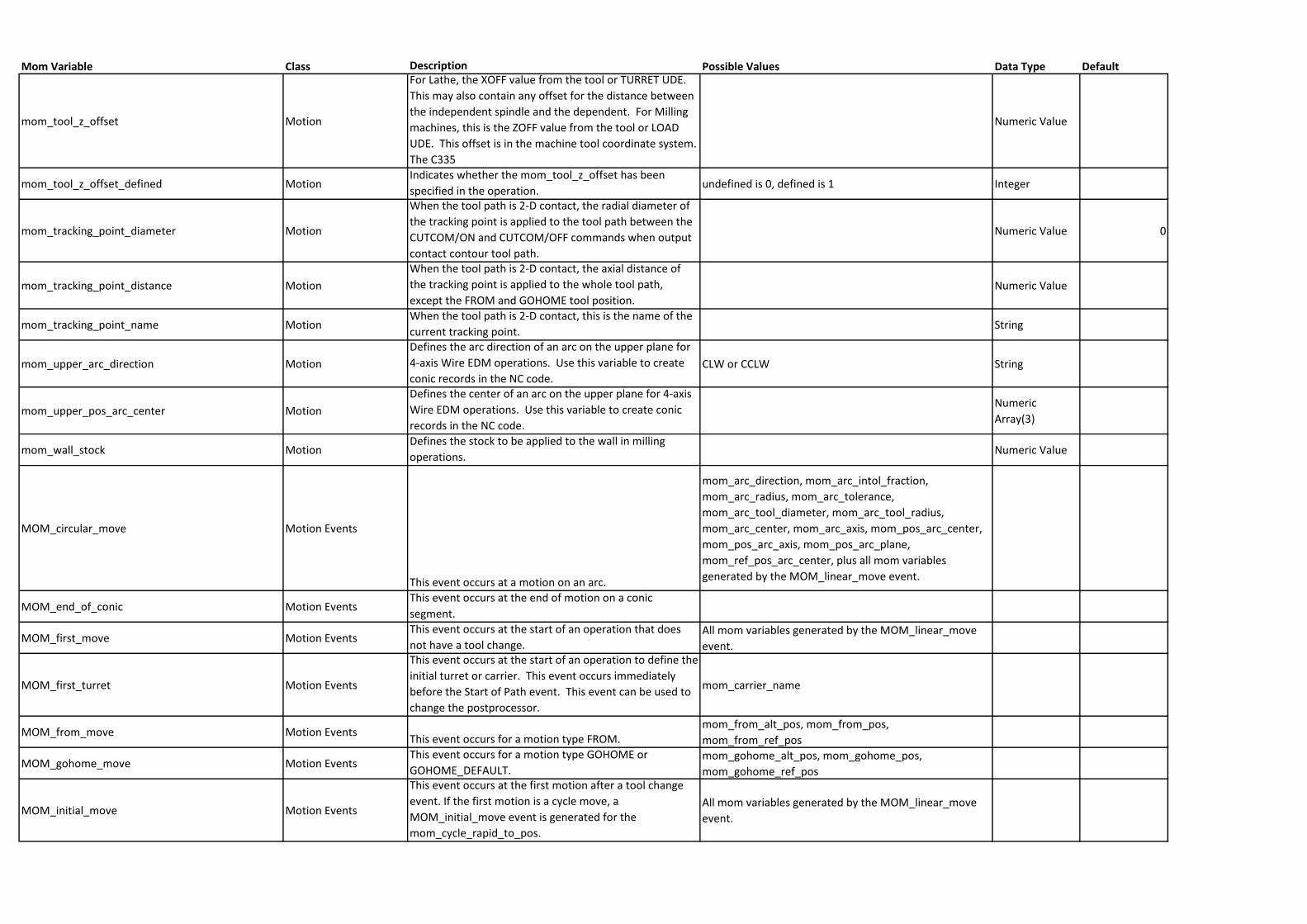
Mom Variable Class Description Possible Values Data Type Default
mom_tool_z_offset Motion
For Lathe, the XOFF value from the tool or TURRET UDE.
This may also contain any offset for the distance between
the independent spindle and the dependent. For Milling
machines, this is the ZOFF value from the tool or LOAD
UDE. This offset is in the machine tool coordinate system.
The C335
Numeric Value
mom_tool_z_offset_defined MotionIndicates whether the mom_tool_z_offset has been
specified in the operation.undefined is 0, defined is 1 Integer
mom_tracking_point_diameter Motion
When the tool path is 2-D contact, the radial diameter of
the tracking point is applied to the tool path between the
CUTCOM/ON and CUTCOM/OFF commands when output
contact contour tool path.
Numeric Value 0
mom_tracking_point_distance Motion
When the tool path is 2-D contact, the axial distance of
the tracking point is applied to the whole tool path,
except the FROM and GOHOME tool position.Numeric Value
mom_tracking_point_name MotionWhen the tool path is 2-D contact, this is the name of the
current tracking point.String
mom_upper_arc_direction Motion
Defines the arc direction of an arc on the upper plane for
4-axis Wire EDM operations. Use this variable to create
conic records in the NC code.CLW or CCLW String
mom_upper_pos_arc_center Motion
Defines the center of an arc on the upper plane for 4-axis
Wire EDM operations. Use this variable to create conic
records in the NC code.
Numeric
Array(3)
mom_wall_stock MotionDefines the stock to be applied to the wall in milling
operations.Numeric Value
MOM_circular_move Motion Events
This event occurs at a motion on an arc.
mom_arc_direction, mom_arc_intol_fraction,
mom_arc_radius, mom_arc_tolerance,
mom_arc_tool_diameter, mom_arc_tool_radius,
mom_arc_center, mom_arc_axis, mom_pos_arc_center,
mom_pos_arc_axis, mom_pos_arc_plane,
mom_ref_pos_arc_center, plus all mom variables
generated by the MOM_linear_move event.
MOM_end_of_conic Motion EventsThis event occurs at the end of motion on a conic
segment.
MOM_first_move Motion EventsThis event occurs at the start of an operation that does
not have a tool change.All mom variables generated by the MOM_linear_move
event.
MOM_first_turret Motion Events
This event occurs at the start of an operation to define the
initial turret or carrier. This event occurs immediately
before the Start of Path event. This event can be used to
change the postprocessor.
mom_carrier_name
MOM_from_move Motion EventsThis event occurs for a motion type FROM.
mom_from_alt_pos, mom_from_pos,
mom_from_ref_pos
MOM_gohome_move Motion EventsThis event occurs for a motion type GOHOME or
GOHOME_DEFAULT.mom_gohome_alt_pos, mom_gohome_pos,
mom_gohome_ref_pos
MOM_initial_move Motion Events
This event occurs at the first motion after a tool change
event. If the first motion is a cycle move, a
MOM_initial_move event is generated for the
mom_cycle_rapid_to_pos.
All mom variables generated by the MOM_linear_move
event.
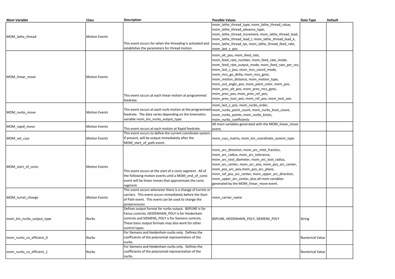
Mom Variable Class Description Possible Values Data Type Default
MOM_lathe_thread Motion Events
This event occurs for when the threading is activated and
establishes the parameters for thread motion.
mom_lathe_thread_type, mom_lathe_thread_value,
mom_lathe_thread_advance_type,
mom_lathe_thread_increment, mom_lathe_thread_lead,
mom_lathe_thread_lead_I, mom_lathe_thread_lead_k,
mom_lathe_thread_tpi, mom_lathe_thread_feed_rate,
mom_last_z_pos
MOM_linear_move Motion Events
This event occurs at each linear motion at programmed
feedrate.
mom_alt_pos, mom_feed_rate,
mom_feed_rate_number, mom_feed_rate_mode,
mom_feed_rate_output_mode, mom_feed_rate_per_rev,
mom_last_z_pos, mom_mcs_coord_mode,
mom_mcs_go_delta, mom_mcs_goto,
mom_motion_distance, mom_motion_type,
mom_out_angle_pos, mom_paint_color, mom_pos,
mom_prev_alt_pos, mom_prev_mcs_goto,
mom_prev_pos, mom_prev_ref_pos,
mom_prev_tool_axis, mom_ref_pos, mom_tool_axis
MOM_nurbs_move Motion EventsThis event occurs at each nurb motion at the programmed
feedrate. The data varies depending on the kinematics
variable mom_kin_nurbs_output_type.
mom_last_z_pos, mom_nurbs_order,
mom_nurbs_point_count, mom_nurbs_knot_count,
mom_nurbs_points, mom_nurbs_knots,
mom_nurbs_coefficients
MOM_rapid_move Motion EventsThis event occurs at each motion at Rapid feedrate.
All mom variables generated with the MOM_linear_move
event.
MOM_set_csys Motion Events
This event occurs to define the current coordinate system.
If present, will be output immediately after the
MOM_start_of_path event.mom_csys_matrix, mom_kin_coordinate_system_type
MOM_start_of_conic Motion EventsThis event occurs at the start of a conic segment. All of
the following motion events until a MOM_end_of_conic
event will be linear moves that approximate the conic
segment.
mom_arc_direction, mom_arc_intol_fraction,
mom_arc_radius, mom_arc_tolerance,
mom_arc_tool_diameter, mom_arc_tool_radius,
mom_arc_center, mom_arc_axis, mom_pos_arc_center,
mom_pos_arc_axis,mom_pos_arc_plane,
mom_ref_pos_arc_center, mom_upper_arc_direction,
mom_upper_arc_center, plus all mom variables
generated by the MOM_linear_move event.
MOM_turret_change Motion Events
This event occurs whenever there is a change of turrets or
carriers. This event occurs immediately before the Start
of Path event. This event can be used to change the
postprocessor.
mom_carrier_name
mom_kin_nurbs_output_type Nurbs
Defines output format for nurbs output. BSPLINE is for
Fanuc controls, HEIDENHAIN_POLY is for Heidenhain
controls and SIEMENS_POLY is for Siemens controls.
These basic output formats may also work for other
control types.
BSPLINE, HEIDENHAIN_POLY, SIEMENS_POLY String
mom_nurbs_co_efficient_0 Nurbs
For Siemens and Heidenhain nurbs only. Defines the
coefficients of the polynomial representation of the
nurbs.Numerical Value
mom_nurbs_co_efficient_1 Nurbs
For Siemens and Heidenhain nurbs only. Defines the
coefficients of the polynomial representation of the
nurbs.Numerical Value
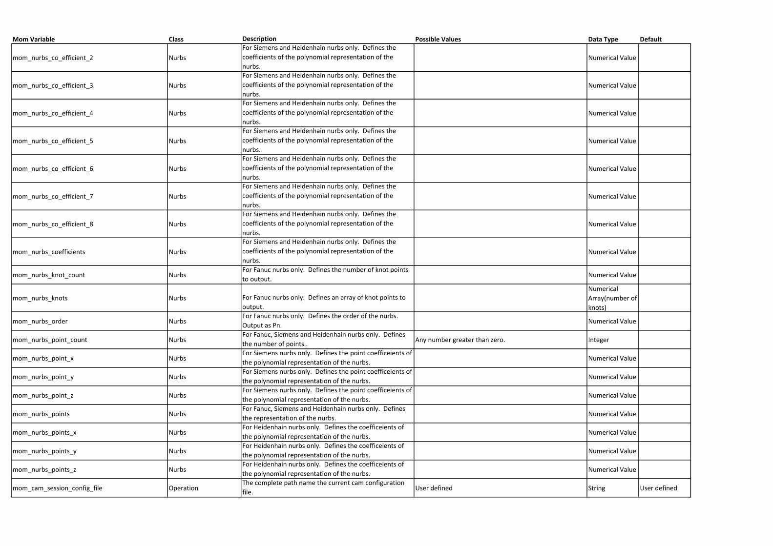
Mom Variable Class Description Possible Values Data Type Default
mom_nurbs_co_efficient_2 Nurbs
For Siemens and Heidenhain nurbs only. Defines the
coefficients of the polynomial representation of the
nurbs.Numerical Value
mom_nurbs_co_efficient_3 Nurbs
For Siemens and Heidenhain nurbs only. Defines the
coefficients of the polynomial representation of the
nurbs.Numerical Value
mom_nurbs_co_efficient_4 Nurbs
For Siemens and Heidenhain nurbs only. Defines the
coefficients of the polynomial representation of the
nurbs.Numerical Value
mom_nurbs_co_efficient_5 Nurbs
For Siemens and Heidenhain nurbs only. Defines the
coefficients of the polynomial representation of the
nurbs.Numerical Value
mom_nurbs_co_efficient_6 Nurbs
For Siemens and Heidenhain nurbs only. Defines the
coefficients of the polynomial representation of the
nurbs.Numerical Value
mom_nurbs_co_efficient_7 Nurbs
For Siemens and Heidenhain nurbs only. Defines the
coefficients of the polynomial representation of the
nurbs.Numerical Value
mom_nurbs_co_efficient_8 Nurbs
For Siemens and Heidenhain nurbs only. Defines the
coefficients of the polynomial representation of the
nurbs.Numerical Value
mom_nurbs_coefficients Nurbs
For Siemens and Heidenhain nurbs only. Defines the
coefficients of the polynomial representation of the
nurbs.Numerical Value
mom_nurbs_knot_count NurbsFor Fanuc nurbs only. Defines the number of knot points
to output.Numerical Value
mom_nurbs_knots Nurbs For Fanuc nurbs only. Defines an array of knot points to
output.
Numerical
Array(number of
knots)
mom_nurbs_order NurbsFor Fanuc nurbs only. Defines the order of the nurbs.
Output as Pn.Numerical Value
mom_nurbs_point_count NurbsFor Fanuc, Siemens and Heidenhain nurbs only. Defines
the number of points..Any number greater than zero. Integer
mom_nurbs_point_x NurbsFor Siemens nurbs only. Defines the point coefficeients of
the polynomial representation of the nurbs.Numerical Value
mom_nurbs_point_y NurbsFor Siemens nurbs only. Defines the point coefficeients of
the polynomial representation of the nurbs.Numerical Value
mom_nurbs_point_z NurbsFor Siemens nurbs only. Defines the point coefficeients of
the polynomial representation of the nurbs.Numerical Value
mom_nurbs_points NurbsFor Fanuc, Siemens and Heidenhain nurbs only. Defines
the representation of the nurbs.Numerical Value
mom_nurbs_points_x NurbsFor Heidenhain nurbs only. Defines the coefficeients of
the polynomial representation of the nurbs.Numerical Value
mom_nurbs_points_y NurbsFor Heidenhain nurbs only. Defines the coefficeients of
the polynomial representation of the nurbs.Numerical Value
mom_nurbs_points_z NurbsFor Heidenhain nurbs only. Defines the coefficeients of
the polynomial representation of the nurbs.Numerical Value
mom_cam_session_config_file OperationThe complete path name the current cam configuration
file.User defined String User defined
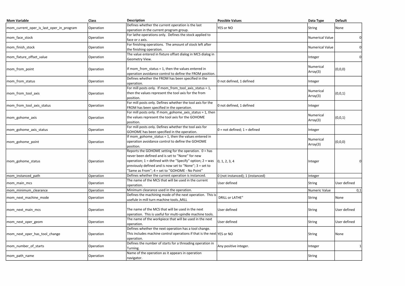
Mom Variable Class Description Possible Values Data Type Default
mom_current_oper_is_last_oper_in_program OperationDefines whether the current operation is the last
operation in the current program group.YES or NO String None
mom_face_stock OperationFor lathe operations only. Defines the stock applied to
face or z axis.Numerical Value 0
mom_finish_stock OperationFor finishing operations. The amount of stock left after
the finishing operation.Numerical Value 0
mom_fixture_offset_value OperationThe value entered in fixture offset dialog in MCS dialog in
Geometry View.Integer 0
mom_from_point Operation If mom_from_status = 1, then the values entered in
operation avoidance control to define the FROM position.
Numerical
Array(3)(0,0,0)
mom_from_status OperationDefines whether the FROM has been specified in the
operation.0 not defined, 1 defined Integer
mom_from_tool_axis Operation
For mill posts only. If mom_from_tool_axis_status = 1,
then the values represent the tool axis for the from
position.
Numerical
Array(3)(0,0,1)
mom_from_tool_axis_status OperationFor mill posts only. Defines whether the tool axis for the
FROM has been specified in the operation.0 not defined, 1 defined Integer
mom_gohome_axis Operation
For mill posts only. If mom_gohome_axis_status = 1, then
the values represent the tool axis for the GOHOME
position.
Numerical
Array(3)(0,0,1)
mom_gohome_axis_status OperationFor mill posts only. Defines whether the tool axis for
GOHOME has been specified in the operation.0 = not defined; 1 = defined Integer
mom_gohome_point Operation
If mom_gohome_status = 1, then the values entered in
operation avoidance control to define the GOHOME
position.
Numerical
Array(3)(0,0,0)
mom_gohome_status Operation
Reports the GOHOME setting for the operation. 0 = has
never been defined and is set to ''None'' for new
operation; 1 = defined with the ''Specify'' option; 2 = was
previously defined and is now set to ''None''; 3 = set to
''Same as From''; 4 = set to ''GOHOME - No Point''
0, 1, 2, 3, 4 Integer 0
mom_instanced_path Operation Defines whether the current operation is instanced. 0 (not instanced); 1 (instanced) Integer
mom_main_mcs OperationThe name of the MCS that will be used in the current
operation. User defined String User defined
mom_minimum_clearance Operation Minimum clearance used in the operation. Numeric Value 0,1
mom_next_machine_mode OperationDefines the machining mode of the next operation. This is
usefule in mill turn machine tools.,MILL DRILL or LATHE" String None
mom_next_main_mcs Operation The name of the MCS that will be used in the next
operation. This is useful for multi-spindle machine tools.User defined String User defined
mom_next_oper_geom OperationThe name of the workpiece that will be used in the next
operation. User defined String User defined
mom_next_oper_has_tool_change Operation
Defines whether the next operation has a tool change.
This includes machine control operations if that is the next
operation.YES or NO String None
mom_number_of_starts OperationDefines the number of starts for a threading operation in
Turning.Any positive integer. Integer 1
mom_path_name OperationName of the operation as it appears in operation
navigator.String
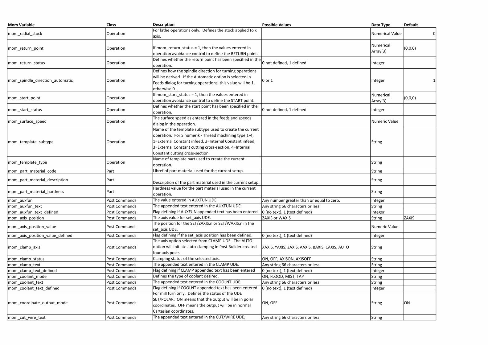
Mom Variable Class Description Possible Values Data Type Default
mom_radial_stock OperationFor lathe operations only. Defines the stock applied to x
axis.Numerical Value 0
mom_return_point Operation If mom_return_status = 1, then the values entered in
operation avoidance control to define the RETURN point.
Numerical
Array(3)(0,0,0)
mom_return_status OperationDefines whether the return point has been specified in the
operation.0 not defined, 1 defined Integer
mom_spindle_direction_automatic Operation
Defines how the spindle direction for turning operations
will be derived. If the Automatic option is selected in
Feeds dialog for turning operations, this value will be 1,
otherwise 0.
0 or 1 Integer 1
mom_start_point OperationIf mom_start_status = 1, then the values entered in
operation avoidance control to define the START point.Numerical
Array(3)(0,0,0)
mom_start_status OperationDefines whether the start point has been specified in the
operation.0 not defined, 1 defined Integer
mom_surface_speed OperationThe surface speed as entered in the feeds and speeds
dialog in the operation.Numeric Value
mom_template_subtype Operation
Name of the template subtype used to create the current
operation. For Sinumerik - Thread machining type 1-4,
1=External Constant infeed, 2=Internal Constant infeed,
3=External Constant cutting cross-section, 4=Internal
Constant cutting cross-section
String
mom_template_type OperationName of template part used to create the current
operation.String
mom_part_material_code Part Libref of part material used for the current setup. String
mom_part_material_description PartDescription of the part material used in the current setup.
String
mom_part_material_hardness PartHardness value for the part material used in the current
operation.String
mom_auxfun Post Commands The value entered in AUXFUN UDE. Any number greater than or equal to zero. Integer
mom_auxfun_text Post Commands The appended text entered in the AUXFUN UDE. Any string 66 characters or less. String
mom_auxfun_text_defined Post Commands Flag defining if AUXFUN appended text has been entered 0 (no text), 1 (text defined) Integer
mom_axis_position Post Commands The axis value for set_axis UDE. ZAXIS or WAXIS String ZAXIS
mom_axis_position_value Post CommandsThe position for the SET/ZAXIS,n or SET/WAXIS,n in the
set_axis UDE.Numeric Value
mom_axis_position_value_defined Post Commands Flag defining if the set_axis position has been defined. 0 (no text), 1 (text defined) Integer
mom_clamp_axis Post Commands
The axis option selected from CLAMP UDE. The AUTO
option will initiate auto-clamping in Post Builder created
four axis posts.XAXIS, YAXIS, ZAXIS, AAXIS, BAXIS, CAXIS, AUTO String
mom_clamp_status Post Commands Clamping status of the selected axis. ON, OFF, AXISON, AXISOFF String
mom_clamp_text Post Commands The appended text entered in the CLAMP UDE. Any string 66 characters or less. String
mom_clamp_text_defined Post Commands Flag defining if CLAMP appended text has been entered 0 (no text), 1 (text defined) Integer
mom_coolant_mode Post Commands Defines the type of coolant desired. ON, FLOOD, MIST, TAP String
mom_coolant_text Post Commands The appended text entered in the COOLNT UDE. Any string 66 characters or less. String
mom_coolant_text_defined Post Commands Flag defining if COOLNT appended text has been entered 0 (no text), 1 (text defined) Integer
mom_coordinate_output_mode Post Commands
For mill turn only. Defines the status of the UDE
SET/POLAR. ON means that the output will be in polar
coordinates. OFF means the output will be in normal
Cartesian coordinates.
ON, OFF String ON
mom_cut_wire_text Post Commands The appended text entered in the CUT/WIRE UDE. Any string 66 characters or less. String
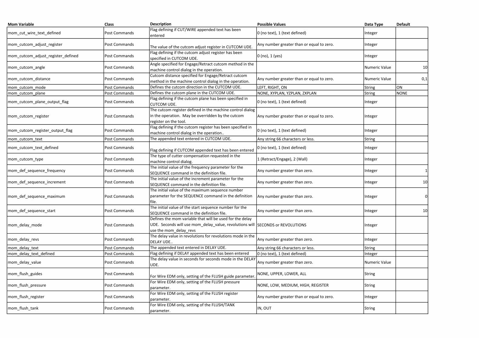
Mom Variable Class Description Possible Values Data Type Default
mom_cut_wire_text_defined Post CommandsFlag defining if CUT/WIRE appended text has been
entered0 (no text), 1 (text defined) Integer
mom_cutcom_adjust_register Post CommandsThe value of the cutcom adjust register in CUTCOM UDE.
Any number greater than or equal to zero. Integer
mom_cutcom_adjust_register_defined Post CommandsFlag defining if the cutcom adjust register has been
specified in CUTCOM UDE.0 (no), 1 (yes) Integer
mom_cutcom_angle Post CommandsAngle specified for Engage/Retract cutcom method in the
machine control dialog in the operation.Numeric Value 10
mom_cutcom_distance Post CommandsCutcom distance specified for Engage/Retract cutcom
method in the machine control dialog in the operation.Any number greater than or equal to zero. Numeric Value 0,1
mom_cutcom_mode Post Commands Defines the cutcom direction in the CUTCOM UDE. LEFT, RIGHT, ON String ON
mom_cutcom_plane Post Commands Defines the cutcom plane in the CUTCOM UDE. NONE, XYPLAN, YZPLAN, ZXPLAN String NONE
mom_cutcom_plane_output_flag Post CommandsFlag defining if the cutcom plane has been specified in
CUTCOM UDE.0 (no text), 1 (text defined) Integer
mom_cutcom_register Post Commands
The cutcom register defined in the machine control dialog
in the operation. May be overridden by the cutcom
register on the tool.Any number greater than or equal to zero. Integer
mom_cutcom_register_output_flag Post CommandsFlag defining if the cutcom register has been specified in
machine control dialog in the operation..0 (no text), 1 (text defined) Integer
mom_cutcom_text Post Commands The appended text entered in CUTCOM UDE. Any string 66 characters or less. String
mom_cutcom_text_defined Post CommandsFlag defining if CUTCOM appended text has been entered
0 (no text), 1 (text defined) Integer
mom_cutcom_type Post CommandsThe type of cutter compensation requested in the
machine control dialog.1 (Retract/Engage), 2 (Wall) Integer
mom_def_sequence_frequency Post CommandsThe initial value of the frequency parameter for the
SEQUENCE command in the definition file.Any number greater than zero. Integer 1
mom_def_sequence_increment Post CommandsThe initial value of the increment parameter for the
SEQUENCE command in the definition file.Any number greater than zero. Integer 10
mom_def_sequence_maximum Post Commands
The initial value of the maximum sequence number
parameter for the SEQUENCE command in the definition
file.Any number greater than zero. Integer 0
mom_def_sequence_start Post CommandsThe initial value of the start sequence number for the
SEQUENCE command in the definition file.Any number greater than zero. Integer 10
mom_delay_mode Post Commands
Defines the mom variable that will be used for the delay
UDE. Seconds will use mom_delay_value, revolutions will
use the mom_delay_revs SECONDS or REVOLUTIONS Integer
mom_delay_revs Post CommandsThe delay value in revolutions for revolutions mode in the
DELAY UDE..Any number greater than zero. Integer
mom_delay_text Post Commands The appended text entered in DELAY UDE. Any string 66 characters or less. String
mom_delay_text_defined Post Commands Flag defining if DELAY appended text has been entered 0 (no text), 1 (text defined) Integer
mom_delay_value Post CommandsThe delay value in seconds for seconds mode in the DELAY
UDE.Any number greater than zero. Numeric Value
mom_flush_guides Post CommandsFor Wire EDM only, setting of the FLUSH guide parameter.
NONE, UPPER, LOWER, ALL String
mom_flush_pressure Post CommandsFor Wire EDM only, setting of the FLUSH pressure
parameter.NONE, LOW, MEDIUM, HIGH, REGISTER String
mom_flush_register Post CommandsFor Wire EDM only, setting of the FLUSH register
parameter.Any number greater than or equal to zero. Integer
mom_flush_tank Post CommandsFor Wire EDM only, setting of the FLUSH/TANK
parameter.IN, OUT String
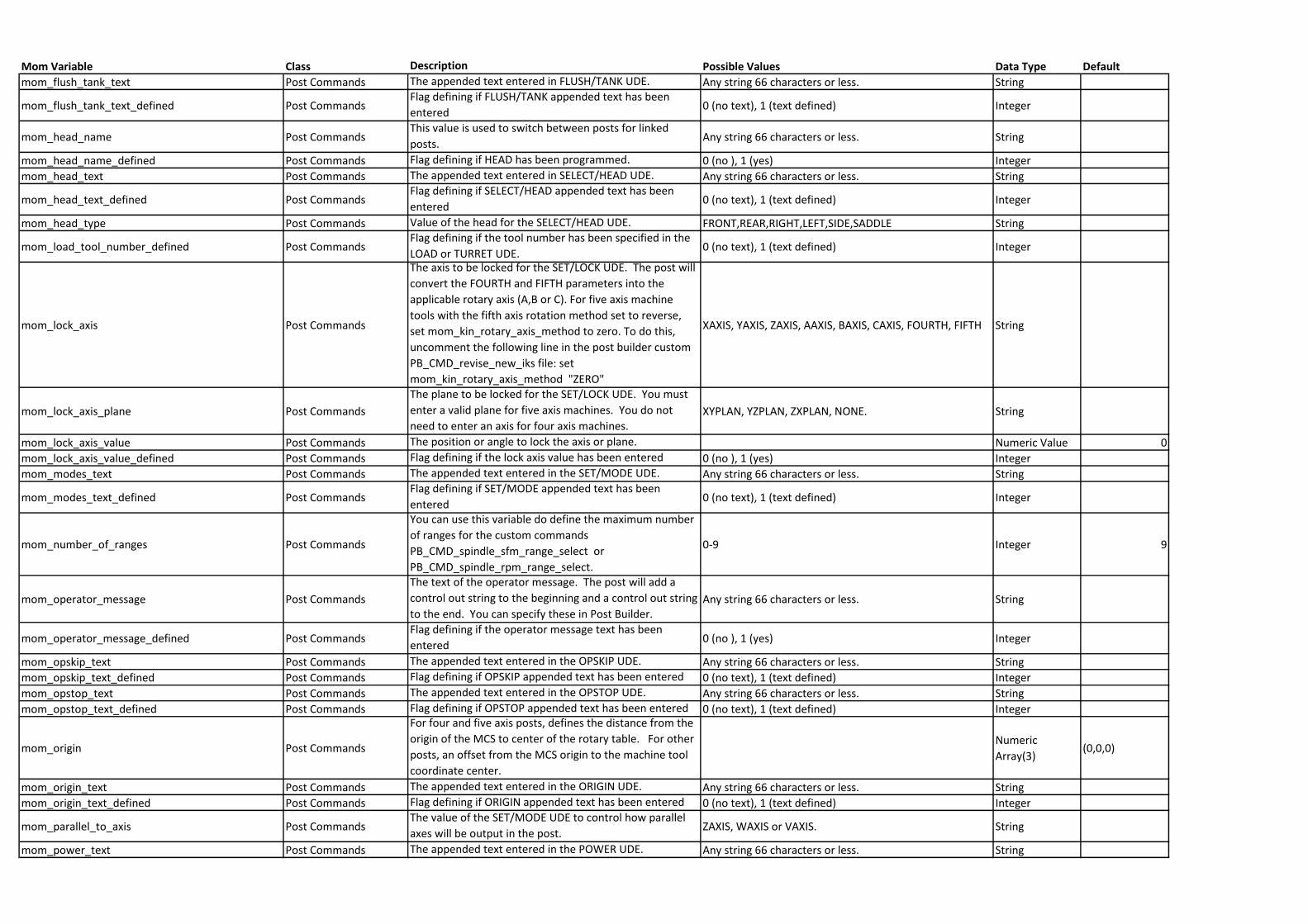
Mom Variable Class Description Possible Values Data Type Default
mom_flush_tank_text Post Commands The appended text entered in FLUSH/TANK UDE. Any string 66 characters or less. String
mom_flush_tank_text_defined Post CommandsFlag defining if FLUSH/TANK appended text has been
entered0 (no text), 1 (text defined) Integer
mom_head_name Post CommandsThis value is used to switch between posts for linked
posts.Any string 66 characters or less. String
mom_head_name_defined Post Commands Flag defining if HEAD has been programmed. 0 (no ), 1 (yes) Integer
mom_head_text Post Commands The appended text entered in SELECT/HEAD UDE. Any string 66 characters or less. String
mom_head_text_defined Post CommandsFlag defining if SELECT/HEAD appended text has been
entered0 (no text), 1 (text defined) Integer
mom_head_type Post Commands Value of the head for the SELECT/HEAD UDE. FRONT,REAR,RIGHT,LEFT,SIDE,SADDLE String
mom_load_tool_number_defined Post CommandsFlag defining if the tool number has been specified in the
LOAD or TURRET UDE.0 (no text), 1 (text defined) Integer
mom_lock_axis Post Commands
The axis to be locked for the SET/LOCK UDE. The post will
convert the FOURTH and FIFTH parameters into the
applicable rotary axis (A,B or C). For five axis machine
tools with the fifth axis rotation method set to reverse,
set mom_kin_rotary_axis_method to zero. To do this,
uncomment the following line in the post builder custom
PB_CMD_revise_new_iks file: set
mom_kin_rotary_axis_method "ZERO"
XAXIS, YAXIS, ZAXIS, AAXIS, BAXIS, CAXIS, FOURTH, FIFTH String
mom_lock_axis_plane Post Commands
The plane to be locked for the SET/LOCK UDE. You must
enter a valid plane for five axis machines. You do not
need to enter an axis for four axis machines.XYPLAN, YZPLAN, ZXPLAN, NONE. String
mom_lock_axis_value Post Commands The position or angle to lock the axis or plane. Numeric Value 0
mom_lock_axis_value_defined Post Commands Flag defining if the lock axis value has been entered 0 (no ), 1 (yes) Integer
mom_modes_text Post Commands The appended text entered in the SET/MODE UDE. Any string 66 characters or less. String
mom_modes_text_defined Post CommandsFlag defining if SET/MODE appended text has been
entered0 (no text), 1 (text defined) Integer
mom_number_of_ranges Post Commands
You can use this variable do define the maximum number
of ranges for the custom commands
PB_CMD_spindle_sfm_range_select or
PB_CMD_spindle_rpm_range_select.
0-9 Integer 9
mom_operator_message Post Commands
The text of the operator message. The post will add a
control out string to the beginning and a control out string
to the end. You can specify these in Post Builder. Any string 66 characters or less. String
mom_operator_message_defined Post CommandsFlag defining if the operator message text has been
entered0 (no ), 1 (yes) Integer
mom_opskip_text Post Commands The appended text entered in the OPSKIP UDE. Any string 66 characters or less. String
mom_opskip_text_defined Post Commands Flag defining if OPSKIP appended text has been entered 0 (no text), 1 (text defined) Integer
mom_opstop_text Post Commands The appended text entered in the OPSTOP UDE. Any string 66 characters or less. String
mom_opstop_text_defined Post Commands Flag defining if OPSTOP appended text has been entered 0 (no text), 1 (text defined) Integer
mom_origin Post Commands
For four and five axis posts, defines the distance from the
origin of the MCS to center of the rotary table. For other
posts, an offset from the MCS origin to the machine tool
coordinate center.
Numeric
Array(3)(0,0,0)
mom_origin_text Post Commands The appended text entered in the ORIGIN UDE. Any string 66 characters or less. String
mom_origin_text_defined Post Commands Flag defining if ORIGIN appended text has been entered 0 (no text), 1 (text defined) Integer
mom_parallel_to_axis Post CommandsThe value of the SET/MODE UDE to control how parallel
axes will be output in the post.ZAXIS, WAXIS or VAXIS. String
mom_power_text Post Commands The appended text entered in the POWER UDE. Any string 66 characters or less. String
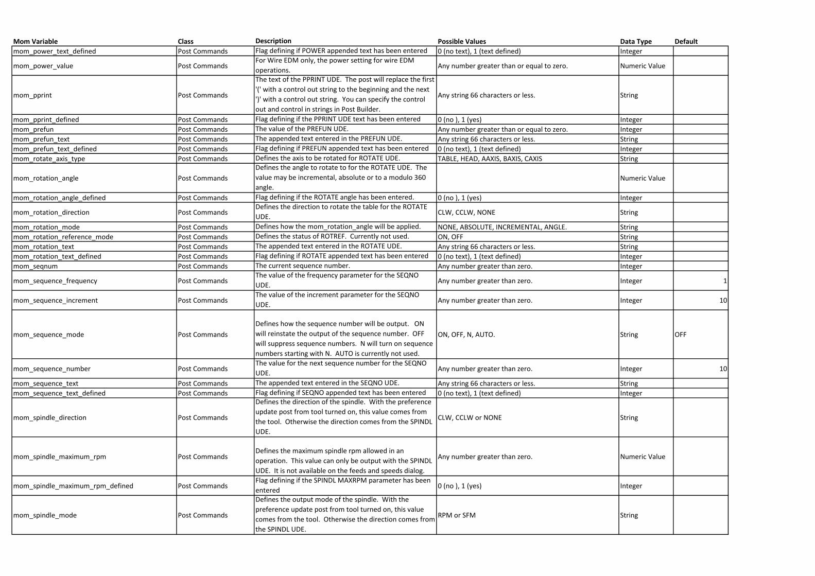
Mom Variable Class Description Possible Values Data Type Default
mom_power_text_defined Post Commands Flag defining if POWER appended text has been entered 0 (no text), 1 (text defined) Integer
mom_power_value Post CommandsFor Wire EDM only, the power setting for wire EDM
operations.Any number greater than or equal to zero. Numeric Value
mom_pprint Post Commands
The text of the PPRINT UDE. The post will replace the first
'(' with a control out string to the beginning and the next
')' with a control out string. You can specify the control
out and control in strings in Post Builder.
Any string 66 characters or less. String
mom_pprint_defined Post Commands Flag defining if the PPRINT UDE text has been entered 0 (no ), 1 (yes) Integer
mom_prefun Post Commands The value of the PREFUN UDE. Any number greater than or equal to zero. Integer
mom_prefun_text Post Commands The appended text entered in the PREFUN UDE. Any string 66 characters or less. String
mom_prefun_text_defined Post Commands Flag defining if PREFUN appended text has been entered 0 (no text), 1 (text defined) Integer
mom_rotate_axis_type Post Commands Defines the axis to be rotated for ROTATE UDE. TABLE, HEAD, AAXIS, BAXIS, CAXIS String
mom_rotation_angle Post Commands
Defines the angle to rotate to for the ROTATE UDE. The
value may be incremental, absolute or to a modulo 360
angle.Numeric Value
mom_rotation_angle_defined Post Commands Flag defining if the ROTATE angle has been entered. 0 (no ), 1 (yes) Integer
mom_rotation_direction Post CommandsDefines the direction to rotate the table for the ROTATE
UDE.CLW, CCLW, NONE String
mom_rotation_mode Post Commands Defines how the mom_rotation_angle will be applied. NONE, ABSOLUTE, INCREMENTAL, ANGLE. String
mom_rotation_reference_mode Post Commands Defines the status of ROTREF. Currently not used. ON, OFF String
mom_rotation_text Post Commands The appended text entered in the ROTATE UDE. Any string 66 characters or less. String
mom_rotation_text_defined Post Commands Flag defining if ROTATE appended text has been entered 0 (no text), 1 (text defined) Integer
mom_seqnum Post Commands The current sequence number. Any number greater than zero. Integer
mom_sequence_frequency Post CommandsThe value of the frequency parameter for the SEQNO
UDE.Any number greater than zero. Integer 1
mom_sequence_increment Post CommandsThe value of the increment parameter for the SEQNO
UDE.Any number greater than zero. Integer 10
mom_sequence_mode Post Commands
Defines how the sequence number will be output. ON
will reinstate the output of the sequence number. OFF
will suppress sequence numbers. N will turn on sequence
numbers starting with N. AUTO is currently not used.
ON, OFF, N, AUTO. String OFF
mom_sequence_number Post CommandsThe value for the next sequence number for the SEQNO
UDE.Any number greater than zero. Integer 10
mom_sequence_text Post Commands The appended text entered in the SEQNO UDE. Any string 66 characters or less. String
mom_sequence_text_defined Post Commands Flag defining if SEQNO appended text has been entered 0 (no text), 1 (text defined) Integer
mom_spindle_direction Post Commands
Defines the direction of the spindle. With the preference
update post from tool turned on, this value comes from
the tool. Otherwise the direction comes from the SPINDL
UDE.
CLW, CCLW or NONE String
mom_spindle_maximum_rpm Post CommandsDefines the maximum spindle rpm allowed in an
operation. This value can only be output with the SPINDL
UDE. It is not available on the feeds and speeds dialog.
Any number greater than zero. Numeric Value
mom_spindle_maximum_rpm_defined Post CommandsFlag defining if the SPINDL MAXRPM parameter has been
entered0 (no ), 1 (yes) Integer
mom_spindle_mode Post Commands
Defines the output mode of the spindle. With the
preference update post from tool turned on, this value
comes from the tool. Otherwise the direction comes from
the SPINDL UDE.
RPM or SFM String
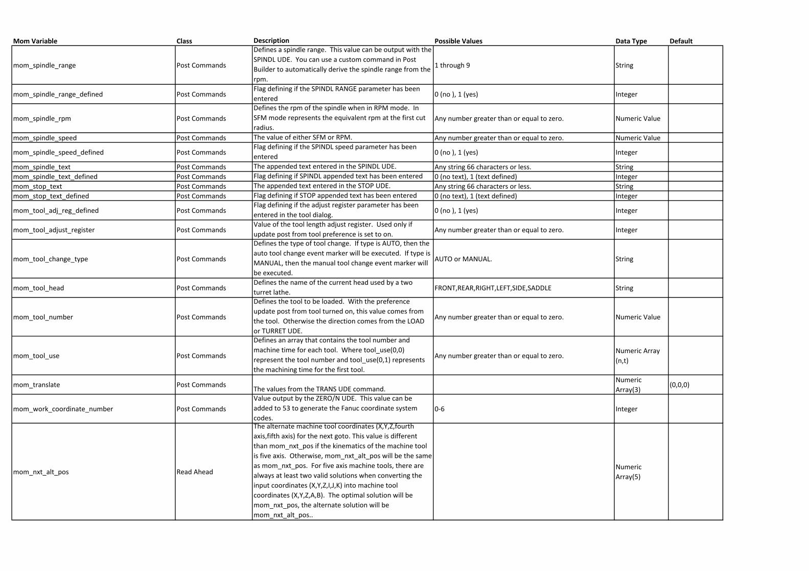
Mom Variable Class Description Possible Values Data Type Default
mom_spindle_range Post Commands
Defines a spindle range. This value can be output with the
SPINDL UDE. You can use a custom command in Post
Builder to automatically derive the spindle range from the
rpm.
1 through 9 String
mom_spindle_range_defined Post CommandsFlag defining if the SPINDL RANGE parameter has been
entered0 (no ), 1 (yes) Integer
mom_spindle_rpm Post Commands
Defines the rpm of the spindle when in RPM mode. In
SFM mode represents the equivalent rpm at the first cut
radius.Any number greater than or equal to zero. Numeric Value
mom_spindle_speed Post Commands The value of either SFM or RPM. Any number greater than or equal to zero. Numeric Value
mom_spindle_speed_defined Post CommandsFlag defining if the SPINDL speed parameter has been
entered0 (no ), 1 (yes) Integer
mom_spindle_text Post Commands The appended text entered in the SPINDL UDE. Any string 66 characters or less. String
mom_spindle_text_defined Post Commands Flag defining if SPINDL appended text has been entered 0 (no text), 1 (text defined) Integer
mom_stop_text Post Commands The appended text entered in the STOP UDE. Any string 66 characters or less. String
mom_stop_text_defined Post Commands Flag defining if STOP appended text has been entered 0 (no text), 1 (text defined) Integer
mom_tool_adj_reg_defined Post CommandsFlag defining if the adjust register parameter has been
entered in the tool dialog.0 (no ), 1 (yes) Integer
mom_tool_adjust_register Post CommandsValue of the tool length adjust register. Used only if
update post from tool preference is set to on.Any number greater than or equal to zero. Integer
mom_tool_change_type Post Commands
Defines the type of tool change. If type is AUTO, then the
auto tool change event marker will be executed. If type is
MANUAL, then the manual tool change event marker will
be executed.
AUTO or MANUAL. String
mom_tool_head Post CommandsDefines the name of the current head used by a two
turret lathe.FRONT,REAR,RIGHT,LEFT,SIDE,SADDLE String
mom_tool_number Post Commands
Defines the tool to be loaded. With the preference
update post from tool turned on, this value comes from
the tool. Otherwise the direction comes from the LOAD
or TURRET UDE.
Any number greater than or equal to zero. Numeric Value
mom_tool_use Post Commands
Defines an array that contains the tool number and
machine time for each tool. Where tool_use(0,0)
represent the tool number and tool_use(0,1) represents
the machining time for the first tool.
Any number greater than or equal to zero.Numeric Array
(n,t)
mom_translate Post CommandsThe values from the TRANS UDE command.
Numeric
Array(3)(0,0,0)
mom_work_coordinate_number Post Commands
Value output by the ZERO/N UDE. This value can be
added to 53 to generate the Fanuc coordinate system
codes.0-6 Integer
mom_nxt_alt_pos Read Ahead
The alternate machine tool coordinates (X,Y,Z,fourth
axis,fifth axis) for the next goto. This value is different
than mom_nxt_pos if the kinematics of the machine tool
is five axis. Otherwise, mom_nxt_alt_pos will be the same
as mom_nxt_pos. For five axis machine tools, there are
always at least two valid solutions when converting the
input coordinates (X,Y,Z,I,J,K) into machine tool
coordinates (X,Y,Z,A,B). The optimal solution will be
mom_nxt_pos, the alternate solution will be
mom_nxt_alt_pos..
Numeric
Array(5)
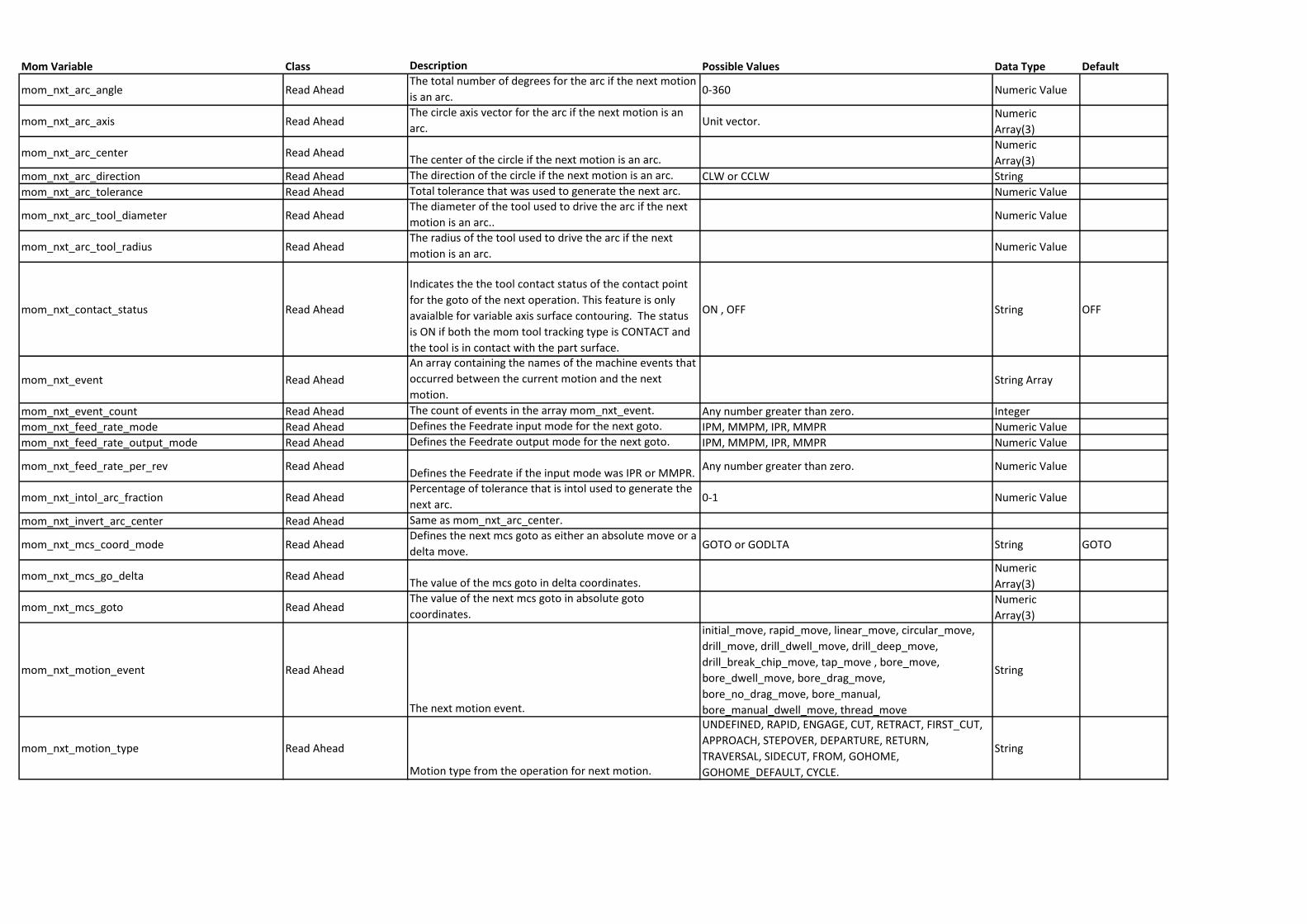
Mom Variable Class Description Possible Values Data Type Default
mom_nxt_arc_angle Read AheadThe total number of degrees for the arc if the next motion
is an arc.0-360 Numeric Value
mom_nxt_arc_axis Read AheadThe circle axis vector for the arc if the next motion is an
arc.Unit vector.
Numeric
Array(3)
mom_nxt_arc_center Read AheadThe center of the circle if the next motion is an arc.
Numeric
Array(3)
mom_nxt_arc_direction Read Ahead The direction of the circle if the next motion is an arc. CLW or CCLW String
mom_nxt_arc_tolerance Read Ahead Total tolerance that was used to generate the next arc. Numeric Value
mom_nxt_arc_tool_diameter Read AheadThe diameter of the tool used to drive the arc if the next
motion is an arc..Numeric Value
mom_nxt_arc_tool_radius Read AheadThe radius of the tool used to drive the arc if the next
motion is an arc.Numeric Value
mom_nxt_contact_status Read Ahead
Indicates the the tool contact status of the contact point
for the goto of the next operation. This feature is only
avaialble for variable axis surface contouring. The status
is ON if both the mom tool tracking type is CONTACT and
the tool is in contact with the part surface.
ON , OFF String OFF
mom_nxt_event Read Ahead
An array containing the names of the machine events that
occurred between the current motion and the next
motion.String Array
mom_nxt_event_count Read Ahead The count of events in the array mom_nxt_event. Any number greater than zero. Integer
mom_nxt_feed_rate_mode Read Ahead Defines the Feedrate input mode for the next goto. IPM, MMPM, IPR, MMPR Numeric Value
mom_nxt_feed_rate_output_mode Read Ahead Defines the Feedrate output mode for the next goto. IPM, MMPM, IPR, MMPR Numeric Value
mom_nxt_feed_rate_per_rev Read AheadDefines the Feedrate if the input mode was IPR or MMPR.
Any number greater than zero. Numeric Value
mom_nxt_intol_arc_fraction Read AheadPercentage of tolerance that is intol used to generate the
next arc.0-1 Numeric Value
mom_nxt_invert_arc_center Read Ahead Same as mom_nxt_arc_center.
mom_nxt_mcs_coord_mode Read AheadDefines the next mcs goto as either an absolute move or a
delta move. GOTO or GODLTA String GOTO
mom_nxt_mcs_go_delta Read AheadThe value of the mcs goto in delta coordinates.
Numeric
Array(3)
mom_nxt_mcs_goto Read AheadThe value of the next mcs goto in absolute goto
coordinates.Numeric
Array(3)
mom_nxt_motion_event Read Ahead
The next motion event.
initial_move, rapid_move, linear_move, circular_move,
drill_move, drill_dwell_move, drill_deep_move,
drill_break_chip_move, tap_move , bore_move,
bore_dwell_move, bore_drag_move,
bore_no_drag_move, bore_manual,
bore_manual_dwell_move, thread_move
String
mom_nxt_motion_type Read Ahead
Motion type from the operation for next motion.
UNDEFINED, RAPID, ENGAGE, CUT, RETRACT, FIRST_CUT,
APPROACH, STEPOVER, DEPARTURE, RETURN,
TRAVERSAL, SIDECUT, FROM, GOHOME,
GOHOME_DEFAULT, CYCLE.
String
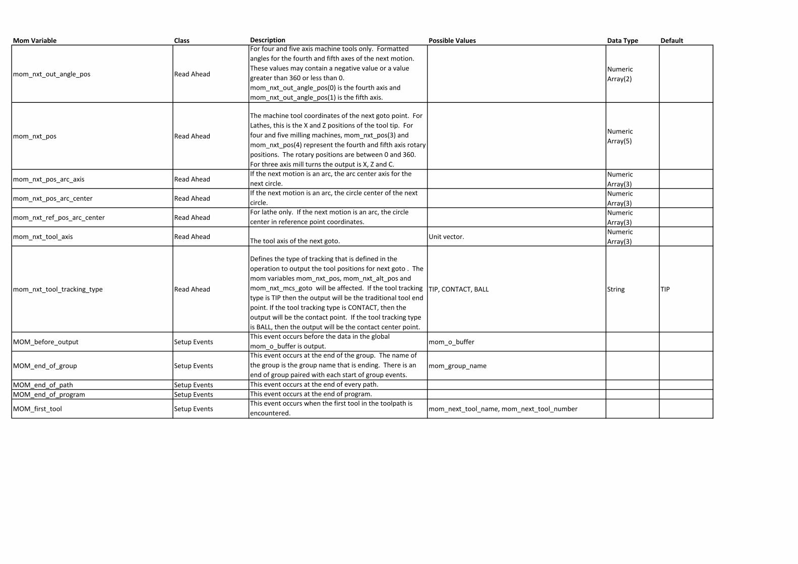
Mom Variable Class Description Possible Values Data Type Default
mom_nxt_out_angle_pos Read Ahead
For four and five axis machine tools only. Formatted
angles for the fourth and fifth axes of the next motion.
These values may contain a negative value or a value
greater than 360 or less than 0.
mom_nxt_out_angle_pos(0) is the fourth axis and
mom_nxt_out_angle_pos(1) is the fifth axis.
Numeric
Array(2)
mom_nxt_pos Read Ahead
The machine tool coordinates of the next goto point. For
Lathes, this is the X and Z positions of the tool tip. For
four and five milling machines, mom_nxt_pos(3) and
mom_nxt_pos(4) represent the fourth and fifth axis rotary
positions. The rotary positions are between 0 and 360.
For three axis mill turns the output is X, Z and C.
Numeric
Array(5)
mom_nxt_pos_arc_axis Read AheadIf the next motion is an arc, the arc center axis for the
next circle.Numeric
Array(3)
mom_nxt_pos_arc_center Read AheadIf the next motion is an arc, the circle center of the next
circle.Numeric
Array(3)
mom_nxt_ref_pos_arc_center Read AheadFor lathe only. If the next motion is an arc, the circle
center in reference point coordinates.Numeric
Array(3)
mom_nxt_tool_axis Read AheadThe tool axis of the next goto.
Unit vector.Numeric
Array(3)
mom_nxt_tool_tracking_type Read Ahead
Defines the type of tracking that is defined in the
operation to output the tool positions for next goto . The
mom variables mom_nxt_pos, mom_nxt_alt_pos and
mom_nxt_mcs_goto will be affected. If the tool tracking
type is TIP then the output will be the traditional tool end
point. If the tool tracking type is CONTACT, then the
output will be the contact point. If the tool tracking type
is BALL, then the output will be the contact center point.
TIP, CONTACT, BALL String TIP
MOM_before_output Setup EventsThis event occurs before the data in the global
mom_o_buffer is output.mom_o_buffer
MOM_end_of_group Setup Events
This event occurs at the end of the group. The name of
the group is the group name that is ending. There is an
end of group paired with each start of group events.mom_group_name
MOM_end_of_path Setup Events This event occurs at the end of every path.
MOM_end_of_program Setup Events This event occurs at the end of program.
MOM_first_tool Setup EventsThis event occurs when the first tool in the toolpath is
encountered. mom_next_tool_name, mom_next_tool_number
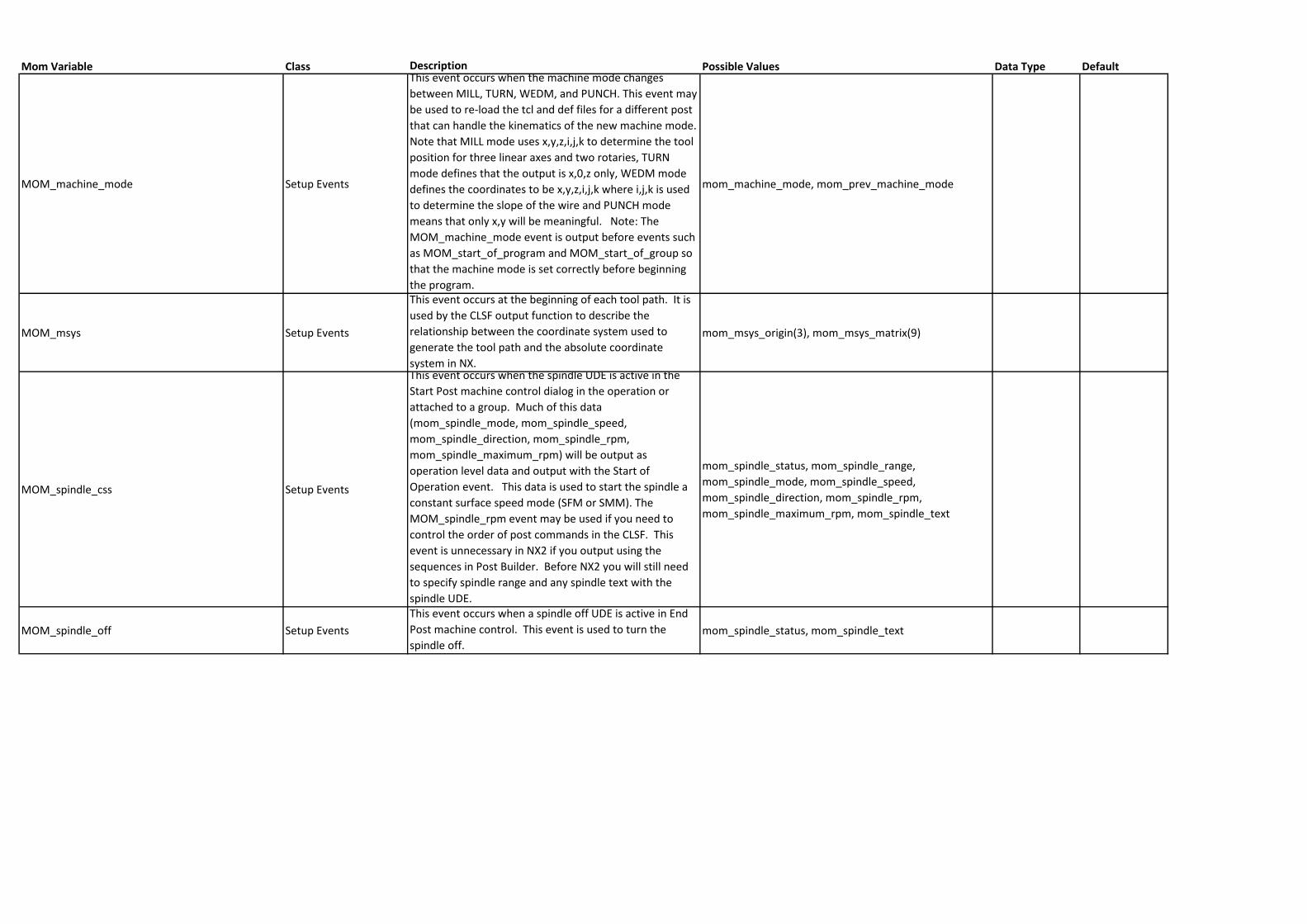
Mom Variable Class Description Possible Values Data Type Default
MOM_machine_mode Setup Events
This event occurs when the machine mode changes
between MILL, TURN, WEDM, and PUNCH. This event may
be used to re-load the tcl and def files for a different post
that can handle the kinematics of the new machine mode.
Note that MILL mode uses x,y,z,i,j,k to determine the tool
position for three linear axes and two rotaries, TURN
mode defines that the output is x,0,z only, WEDM mode
defines the coordinates to be x,y,z,i,j,k where i,j,k is used
to determine the slope of the wire and PUNCH mode
means that only x,y will be meaningful. Note: The
MOM_machine_mode event is output before events such
as MOM_start_of_program and MOM_start_of_group so
that the machine mode is set correctly before beginning
the program.
mom_machine_mode, mom_prev_machine_mode
MOM_msys Setup Events
This event occurs at the beginning of each tool path. It is
used by the CLSF output function to describe the
relationship between the coordinate system used to
generate the tool path and the absolute coordinate
system in NX.
mom_msys_origin(3), mom_msys_matrix(9)
MOM_spindle_css Setup Events
This event occurs when the spindle UDE is active in the
Start Post machine control dialog in the operation or
attached to a group. Much of this data
(mom_spindle_mode, mom_spindle_speed,
mom_spindle_direction, mom_spindle_rpm,
mom_spindle_maximum_rpm) will be output as
operation level data and output with the Start of
Operation event. This data is used to start the spindle a
constant surface speed mode (SFM or SMM). The
MOM_spindle_rpm event may be used if you need to
control the order of post commands in the CLSF. This
event is unnecessary in NX2 if you output using the
sequences in Post Builder. Before NX2 you will still need
to specify spindle range and any spindle text with the
spindle UDE.
mom_spindle_status, mom_spindle_range,
mom_spindle_mode, mom_spindle_speed,
mom_spindle_direction, mom_spindle_rpm,
mom_spindle_maximum_rpm, mom_spindle_text
MOM_spindle_off Setup Events
This event occurs when a spindle off UDE is active in End
Post machine control. This event is used to turn the
spindle off.mom_spindle_status, mom_spindle_text
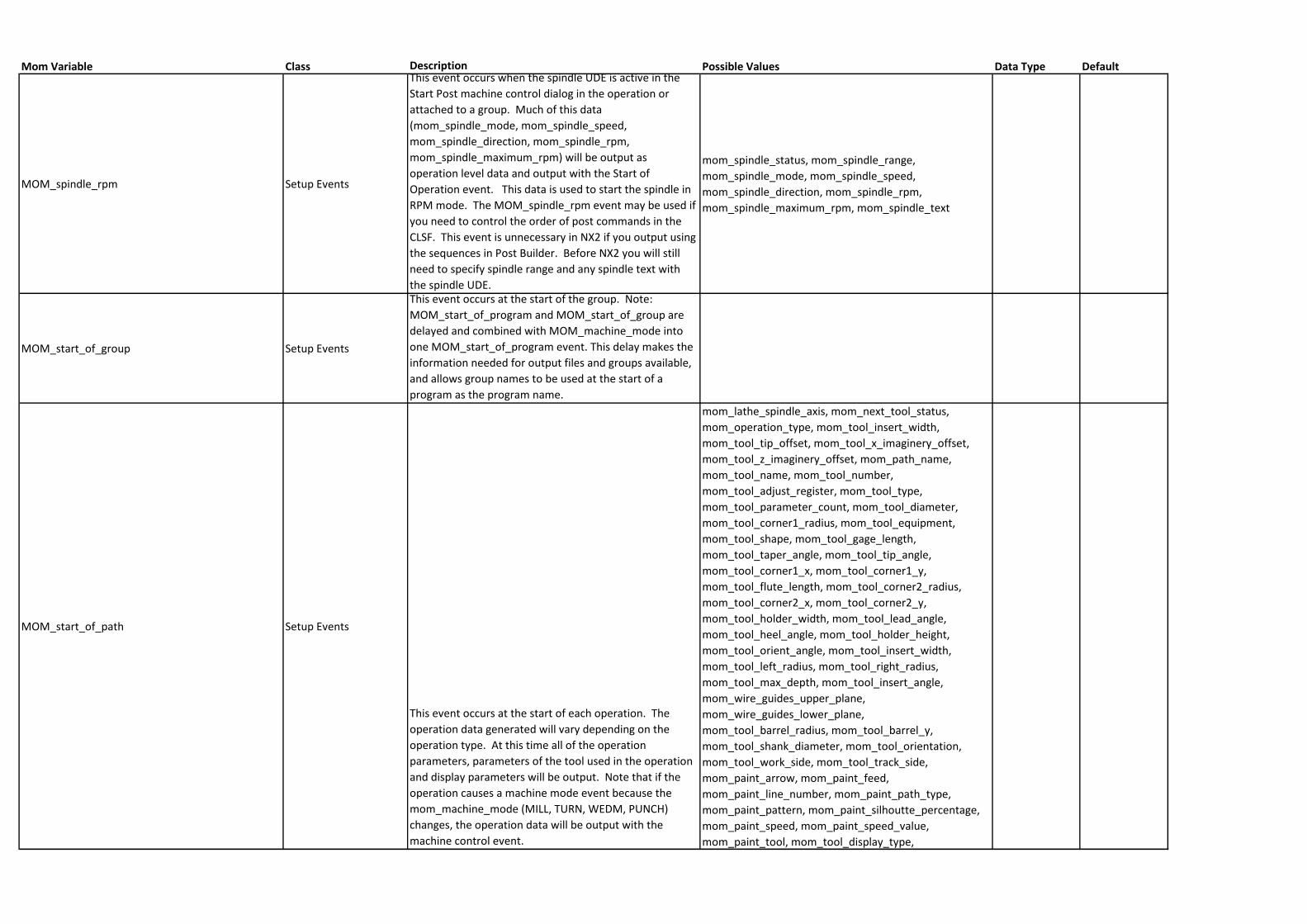
Mom Variable Class Description Possible Values Data Type Default
MOM_spindle_rpm Setup Events
This event occurs when the spindle UDE is active in the
Start Post machine control dialog in the operation or
attached to a group. Much of this data
(mom_spindle_mode, mom_spindle_speed,
mom_spindle_direction, mom_spindle_rpm,
mom_spindle_maximum_rpm) will be output as
operation level data and output with the Start of
Operation event. This data is used to start the spindle in
RPM mode. The MOM_spindle_rpm event may be used if
you need to control the order of post commands in the
CLSF. This event is unnecessary in NX2 if you output using
the sequences in Post Builder. Before NX2 you will still
need to specify spindle range and any spindle text with
the spindle UDE.
mom_spindle_status, mom_spindle_range,
mom_spindle_mode, mom_spindle_speed,
mom_spindle_direction, mom_spindle_rpm,
mom_spindle_maximum_rpm, mom_spindle_text
MOM_start_of_group Setup Events
This event occurs at the start of the group. Note:
MOM_start_of_program and MOM_start_of_group are
delayed and combined with MOM_machine_mode into
one MOM_start_of_program event. This delay makes the
information needed for output files and groups available,
and allows group names to be used at the start of a
program as the program name.
MOM_start_of_path Setup Events
This event occurs at the start of each operation. The
operation data generated will vary depending on the
operation type. At this time all of the operation
parameters, parameters of the tool used in the operation
and display parameters will be output. Note that if the
operation causes a machine mode event because the
mom_machine_mode (MILL, TURN, WEDM, PUNCH)
changes, the operation data will be output with the
machine control event.
mom_lathe_spindle_axis, mom_next_tool_status,
mom_operation_type, mom_tool_insert_width,
mom_tool_tip_offset, mom_tool_x_imaginery_offset,
mom_tool_z_imaginery_offset, mom_path_name,
mom_tool_name, mom_tool_number,
mom_tool_adjust_register, mom_tool_type,
mom_tool_parameter_count, mom_tool_diameter,
mom_tool_corner1_radius, mom_tool_equipment,
mom_tool_shape, mom_tool_gage_length,
mom_tool_taper_angle, mom_tool_tip_angle,
mom_tool_corner1_x, mom_tool_corner1_y,
mom_tool_flute_length, mom_tool_corner2_radius,
mom_tool_corner2_x, mom_tool_corner2_y,
mom_tool_holder_width, mom_tool_lead_angle,
mom_tool_heel_angle, mom_tool_holder_height,
mom_tool_orient_angle, mom_tool_insert_width,
mom_tool_left_radius, mom_tool_right_radius,
mom_tool_max_depth, mom_tool_insert_angle,
mom_wire_guides_upper_plane,
mom_wire_guides_lower_plane,
mom_tool_barrel_radius, mom_tool_barrel_y,
mom_tool_shank_diameter, mom_tool_orientation,
mom_tool_work_side, mom_tool_track_side,
mom_paint_arrow, mom_paint_feed,
mom_paint_line_number, mom_paint_path_type,
mom_paint_pattern, mom_paint_silhoutte_percentage,
mom_paint_speed, mom_paint_speed_value,
mom_paint_tool, mom_tool_display_type,
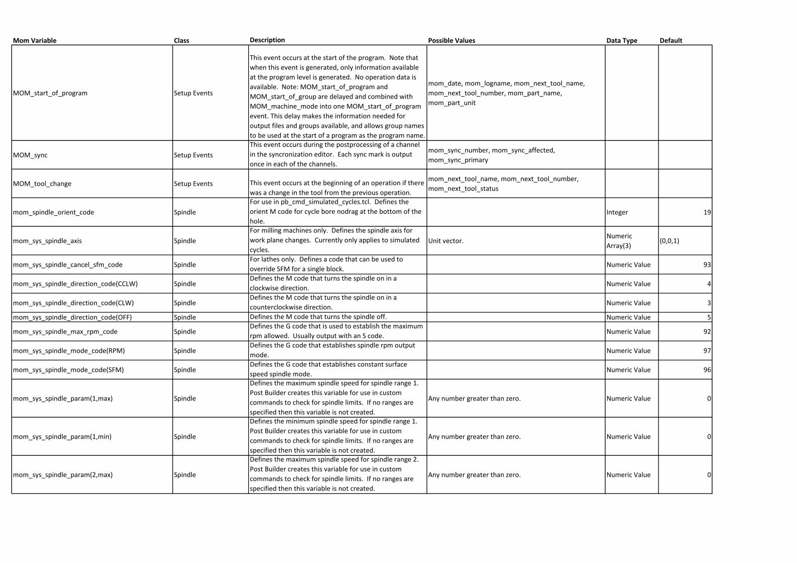
Mom Variable Class Description Possible Values Data Type Default
MOM_start_of_program Setup Events
This event occurs at the start of the program. Note that
when this event is generated, only information available
at the program level is generated. No operation data is
available. Note: MOM_start_of_program and
MOM_start_of_group are delayed and combined with
MOM_machine_mode into one MOM_start_of_program
event. This delay makes the information needed for
output files and groups available, and allows group names
to be used at the start of a program as the program name.
mom_date, mom_logname, mom_next_tool_name,
mom_next_tool_number, mom_part_name,
mom_part_unit
MOM_sync Setup Events
This event occurs during the postprocessing of a channel
in the syncronization editor. Each sync mark is output
once in each of the channels.
mom_sync_number, mom_sync_affected,
mom_sync_primary
MOM_tool_change Setup Events This event occurs at the beginning of an operation if there
was a change in the tool from the previous operation.
mom_next_tool_name, mom_next_tool_number,
mom_next_tool_status
mom_spindle_orient_code Spindle
For use in pb_cmd_simulated_cycles.tcl. Defines the
orient M code for cycle bore nodrag at the bottom of the
hole.Integer 19
mom_sys_spindle_axis Spindle
For milling machines only. Defines the spindle axis for
work plane changes. Currently only applies to simulated
cycles.Unit vector.
Numeric
Array(3)(0,0,1)
mom_sys_spindle_cancel_sfm_code SpindleFor lathes only. Defines a code that can be used to
override SFM for a single block.Numeric Value 93
mom_sys_spindle_direction_code(CCLW) SpindleDefines the M code that turns the spindle on in a
clockwise direction.Numeric Value 4
mom_sys_spindle_direction_code(CLW) SpindleDefines the M code that turns the spindle on in a
counterclockwise direction.Numeric Value 3
mom_sys_spindle_direction_code(OFF) Spindle Defines the M code that turns the spindle off. Numeric Value 5
mom_sys_spindle_max_rpm_code SpindleDefines the G code that is used to establish the maximum
rpm allowed. Usually output with an S code.Numeric Value 92
mom_sys_spindle_mode_code(RPM) SpindleDefines the G code that establishes spindle rpm output
mode.Numeric Value 97
mom_sys_spindle_mode_code(SFM) SpindleDefines the G code that establishes constant surface
speed spindle mode.Numeric Value 96
mom_sys_spindle_param(1,max) Spindle
Defines the maximum spindle speed for spindle range 1.
Post Builder creates this variable for use in custom
commands to check for spindle limits. If no ranges are
specified then this variable is not created.
Any number greater than zero. Numeric Value 0
mom_sys_spindle_param(1,min) Spindle
Defines the minimum spindle speed for spindle range 1.
Post Builder creates this variable for use in custom
commands to check for spindle limits. If no ranges are
specified then this variable is not created.
Any number greater than zero. Numeric Value 0
mom_sys_spindle_param(2,max) Spindle
Defines the maximum spindle speed for spindle range 2.
Post Builder creates this variable for use in custom
commands to check for spindle limits. If no ranges are
specified then this variable is not created.
Any number greater than zero. Numeric Value 0
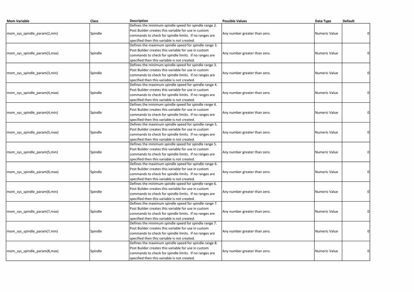
Mom Variable Class Description Possible Values Data Type Default
mom_sys_spindle_param(2,min) Spindle
Defines the minimum spindle speed for spindle range 2.
Post Builder creates this variable for use in custom
commands to check for spindle limits. If no ranges are
specified then this variable is not created.
Any number greater than zero. Numeric Value 0
mom_sys_spindle_param(3,max) Spindle
Defines the maximum spindle speed for spindle range 3.
Post Builder creates this variable for use in custom
commands to check for spindle limits. If no ranges are
specified then this variable is not created.
Any number greater than zero. Numeric Value 0
mom_sys_spindle_param(3,min) Spindle
Defines the minimum spindle speed for spindle range 3.
Post Builder creates this variable for use in custom
commands to check for spindle limits. If no ranges are
specified then this variable is not created.
Any number greater than zero. Numeric Value 0
mom_sys_spindle_param(4,max) Spindle
Defines the maximum spindle speed for spindle range 4.
Post Builder creates this variable for use in custom
commands to check for spindle limits. If no ranges are
specified then this variable is not created.
Any number greater than zero. Numeric Value 0
mom_sys_spindle_param(4,min) Spindle
Defines the minimum spindle speed for spindle range 4.
Post Builder creates this variable for use in custom
commands to check for spindle limits. If no ranges are
specified then this variable is not created.
Any number greater than zero. Numeric Value 0
mom_sys_spindle_param(5,max) Spindle
Defines the maximum spindle speed for spindle range 5.
Post Builder creates this variable for use in custom
commands to check for spindle limits. If no ranges are
specified then this variable is not created.
Any number greater than zero. Numeric Value 0
mom_sys_spindle_param(5,min) Spindle
Defines the minimum spindle speed for spindle range 5.
Post Builder creates this variable for use in custom
commands to check for spindle limits. If no ranges are
specified then this variable is not created.
Any number greater than zero. Numeric Value 0
mom_sys_spindle_param(6,max) Spindle
Defines the maximum spindle speed for spindle range 6.
Post Builder creates this variable for use in custom
commands to check for spindle limits. If no ranges are
specified then this variable is not created.
Any number greater than zero. Numeric Value 0
mom_sys_spindle_param(6,min) Spindle
Defines the minimum spindle speed for spindle range 6.
Post Builder creates this variable for use in custom
commands to check for spindle limits. If no ranges are
specified then this variable is not created.
Any number greater than zero. Numeric Value 0
mom_sys_spindle_param(7,max) Spindle
Defines the maximum spindle speed for spindle range 7.
Post Builder creates this variable for use in custom
commands to check for spindle limits. If no ranges are
specified then this variable is not created.
Any number greater than zero. Numeric Value 0
mom_sys_spindle_param(7,min) Spindle
Defines the minimum spindle speed for spindle range 7.
Post Builder creates this variable for use in custom
commands to check for spindle limits. If no ranges are
specified then this variable is not created.
Any number greater than zero. Numeric Value 0
mom_sys_spindle_param(8,max) Spindle
Defines the maximum spindle speed for spindle range 8.
Post Builder creates this variable for use in custom
commands to check for spindle limits. If no ranges are
specified then this variable is not created.
Any number greater than zero. Numeric Value 0
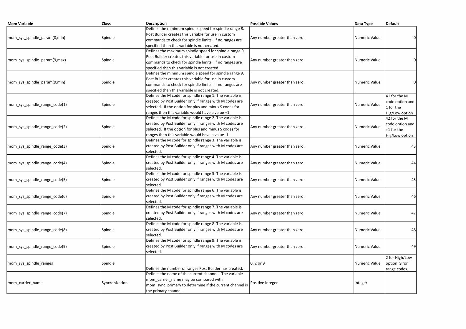
Mom Variable Class Description Possible Values Data Type Default
mom_sys_spindle_param(8,min) Spindle
Defines the minimum spindle speed for spindle range 8.
Post Builder creates this variable for use in custom
commands to check for spindle limits. If no ranges are
specified then this variable is not created.
Any number greater than zero. Numeric Value 0
mom_sys_spindle_param(9,max) Spindle
Defines the maximum spindle speed for spindle range 9.
Post Builder creates this variable for use in custom
commands to check for spindle limits. If no ranges are
specified then this variable is not created.
Any number greater than zero. Numeric Value 0
mom_sys_spindle_param(9,min) Spindle
Defines the minimum spindle speed for spindle range 9.
Post Builder creates this variable for use in custom
commands to check for spindle limits. If no ranges are
specified then this variable is not created.
Any number greater than zero. Numeric Value 0
mom_sys_spindle_range_code(1) Spindle
Defines the M code for spindle range 1. The variable is
created by Post Builder only if ranges with M codes are
selected. If the option for plus and minus S codes for
ranges then this variable would have a value +1.
Any number greater than zero. Numeric Value
41 for the M
code option and -
1 for the
Hig/Low option
mom_sys_spindle_range_code(2) Spindle
Defines the M code for spindle range 2. The variable is
created by Post Builder only if ranges with M codes are
selected. If the option for plus and minus S codes for
ranges then this variable would have a value -1.
Any number greater than zero. Numeric Value
42 for the M
code option and
+1 for the
Hig/Low option
mom_sys_spindle_range_code(3) Spindle
Defines the M code for spindle range 3. The variable is
created by Post Builder only if ranges with M codes are
selected. Any number greater than zero. Numeric Value 43
mom_sys_spindle_range_code(4) Spindle
Defines the M code for spindle range 4. The variable is
created by Post Builder only if ranges with M codes are
selected. Any number greater than zero. Numeric Value 44
mom_sys_spindle_range_code(5) Spindle
Defines the M code for spindle range 5. The variable is
created by Post Builder only if ranges with M codes are
selected. Any number greater than zero. Numeric Value 45
mom_sys_spindle_range_code(6) Spindle
Defines the M code for spindle range 6. The variable is
created by Post Builder only if ranges with M codes are
selected. Any number greater than zero. Numeric Value 46
mom_sys_spindle_range_code(7) Spindle
Defines the M code for spindle range 7. The variable is
created by Post Builder only if ranges with M codes are
selected. Any number greater than zero. Numeric Value 47
mom_sys_spindle_range_code(8) Spindle
Defines the M code for spindle range 8. The variable is
created by Post Builder only if ranges with M codes are
selected. Any number greater than zero. Numeric Value 48
mom_sys_spindle_range_code(9) Spindle
Defines the M code for spindle range 9. The variable is
created by Post Builder only if ranges with M codes are
selected. Any number greater than zero. Numeric Value 49
mom_sys_spindle_ranges SpindleDefines the number of ranges Post Builder has created.
0, 2 or 9 Numeric Value
2 for High/Low
option, 9 for
range codes.
mom_carrier_name Syncronization
Defines the name of the current channel. The variable
mom_carrier_name may be compared with
mom_sync_primary to determine if the current channel is
the primary channel.
Positive Integer Integer
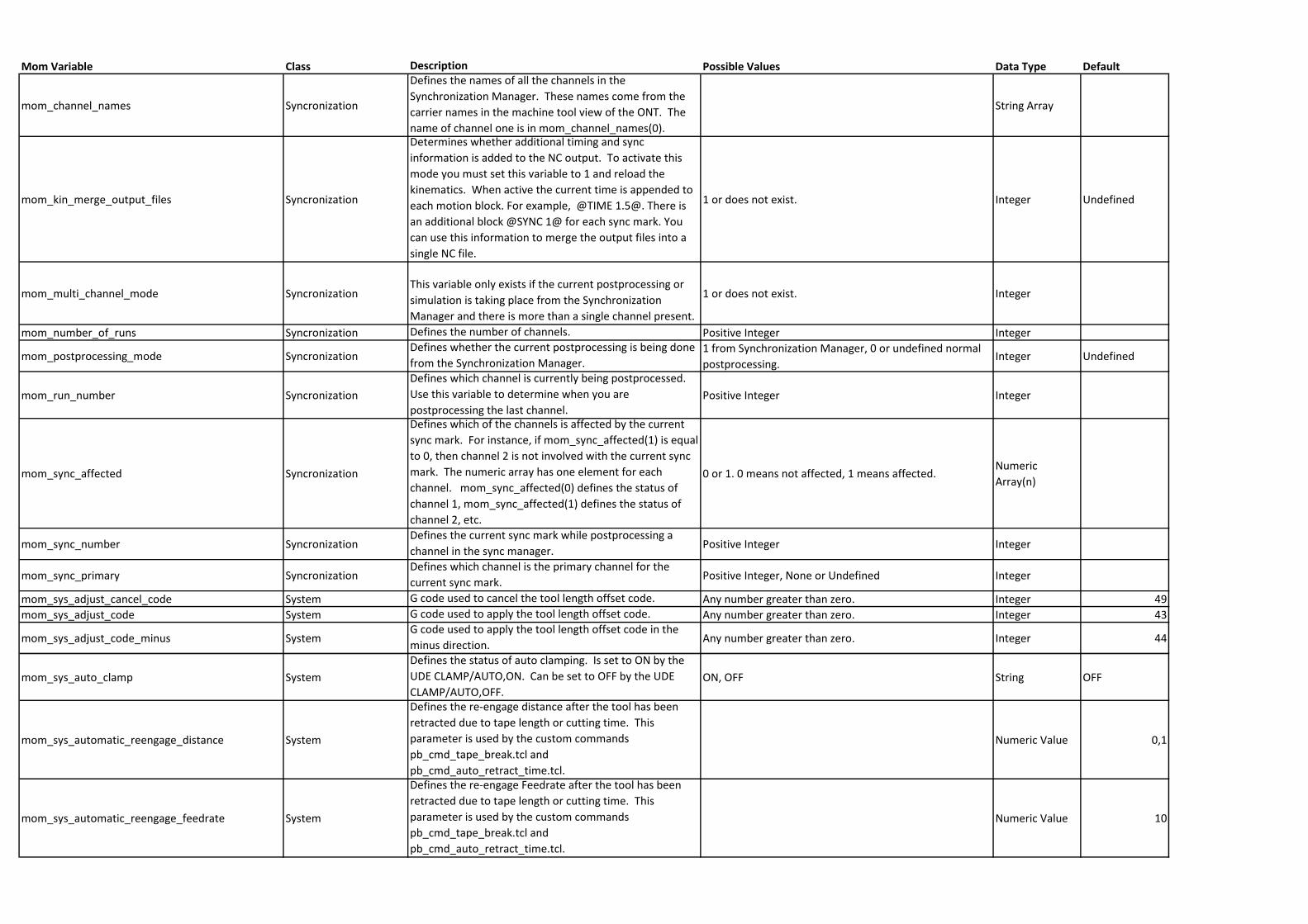
Mom Variable Class Description Possible Values Data Type Default
mom_channel_names Syncronization
Defines the names of all the channels in the
Synchronization Manager. These names come from the
carrier names in the machine tool view of the ONT. The
name of channel one is in mom_channel_names(0).
String Array
mom_kin_merge_output_files Syncronization
Determines whether additional timing and sync
information is added to the NC output. To activate this
mode you must set this variable to 1 and reload the
kinematics. When active the current time is appended to
each motion block. For example, @TIME 1.5@. There is
an additional block @SYNC 1@ for each sync mark. You
can use this information to merge the output files into a
single NC file.
1 or does not exist. Integer Undefined
mom_multi_channel_mode SyncronizationThis variable only exists if the current postprocessing or
simulation is taking place from the Synchronization
Manager and there is more than a single channel present.
1 or does not exist. Integer
mom_number_of_runs Syncronization Defines the number of channels. Positive Integer Integer
mom_postprocessing_mode SyncronizationDefines whether the current postprocessing is being done
from the Synchronization Manager.1 from Synchronization Manager, 0 or undefined normal
postprocessing.Integer Undefined
mom_run_number Syncronization
Defines which channel is currently being postprocessed.
Use this variable to determine when you are
postprocessing the last channel.Positive Integer Integer
mom_sync_affected Syncronization
Defines which of the channels is affected by the current
sync mark. For instance, if mom_sync_affected(1) is equal
to 0, then channel 2 is not involved with the current sync
mark. The numeric array has one element for each
channel. mom_sync_affected(0) defines the status of
channel 1, mom_sync_affected(1) defines the status of
channel 2, etc.
0 or 1. 0 means not affected, 1 means affected.Numeric
Array(n)
mom_sync_number SyncronizationDefines the current sync mark while postprocessing a
channel in the sync manager.Positive Integer Integer
mom_sync_primary SyncronizationDefines which channel is the primary channel for the
current sync mark.Positive Integer, None or Undefined Integer
mom_sys_adjust_cancel_code System G code used to cancel the tool length offset code. Any number greater than zero. Integer 49
mom_sys_adjust_code System G code used to apply the tool length offset code. Any number greater than zero. Integer 43
mom_sys_adjust_code_minus SystemG code used to apply the tool length offset code in the
minus direction.Any number greater than zero. Integer 44
mom_sys_auto_clamp System
Defines the status of auto clamping. Is set to ON by the
UDE CLAMP/AUTO,ON. Can be set to OFF by the UDE
CLAMP/AUTO,OFF.ON, OFF String OFF
mom_sys_automatic_reengage_distance System
Defines the re-engage distance after the tool has been
retracted due to tape length or cutting time. This
parameter is used by the custom commands
pb_cmd_tape_break.tcl and
pb_cmd_auto_retract_time.tcl.
Numeric Value 0,1
mom_sys_automatic_reengage_feedrate System
Defines the re-engage Feedrate after the tool has been
retracted due to tape length or cutting time. This
parameter is used by the custom commands
pb_cmd_tape_break.tcl and
pb_cmd_auto_retract_time.tcl.
Numeric Value 10
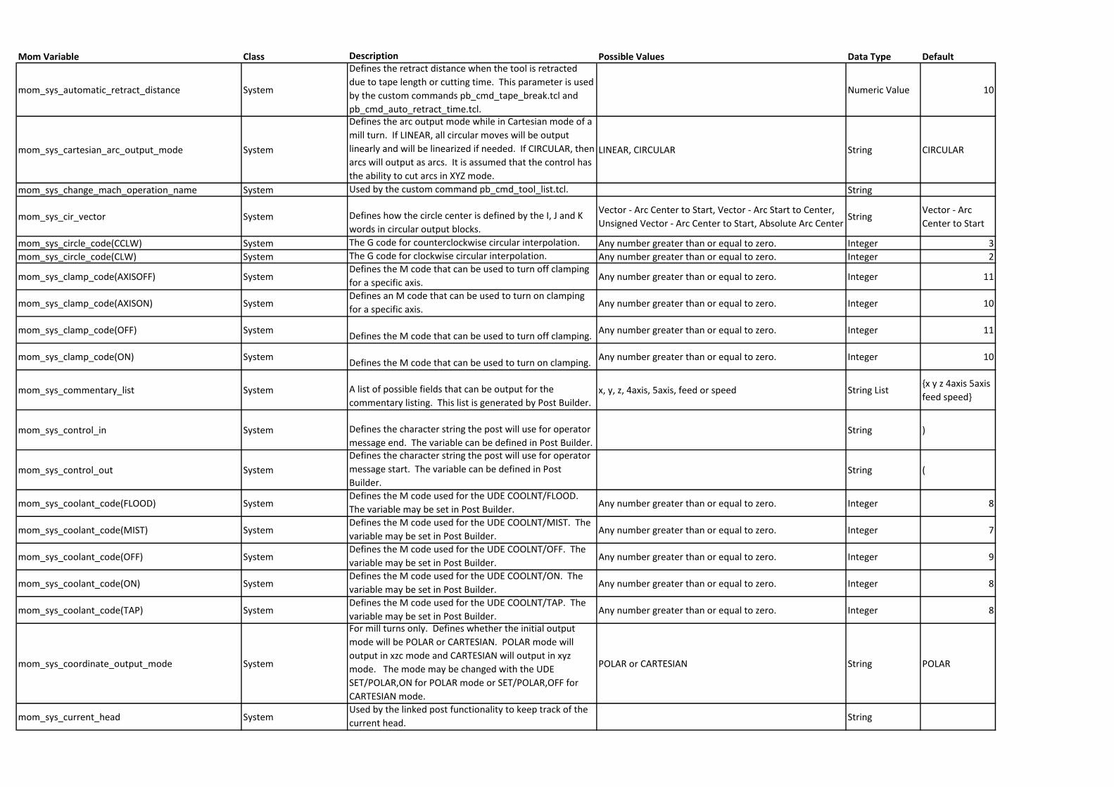
Mom Variable Class Description Possible Values Data Type Default
mom_sys_automatic_retract_distance System
Defines the retract distance when the tool is retracted
due to tape length or cutting time. This parameter is used
by the custom commands pb_cmd_tape_break.tcl and
pb_cmd_auto_retract_time.tcl.
Numeric Value 10
mom_sys_cartesian_arc_output_mode System
Defines the arc output mode while in Cartesian mode of a
mill turn. If LINEAR, all circular moves will be output
linearly and will be linearized if needed. If CIRCULAR, then
arcs will output as arcs. It is assumed that the control has
the ability to cut arcs in XYZ mode.
LINEAR, CIRCULAR String CIRCULAR
mom_sys_change_mach_operation_name System Used by the custom command pb_cmd_tool_list.tcl. String
mom_sys_cir_vector System Defines how the circle center is defined by the I, J and K
words in circular output blocks.
Vector - Arc Center to Start, Vector - Arc Start to Center,
Unsigned Vector - Arc Center to Start, Absolute Arc CenterString
Vector - Arc
Center to Start
mom_sys_circle_code(CCLW) System The G code for counterclockwise circular interpolation. Any number greater than or equal to zero. Integer 3
mom_sys_circle_code(CLW) System The G code for clockwise circular interpolation. Any number greater than or equal to zero. Integer 2
mom_sys_clamp_code(AXISOFF) SystemDefines the M code that can be used to turn off clamping
for a specific axis. Any number greater than or equal to zero. Integer 11
mom_sys_clamp_code(AXISON) SystemDefines an M code that can be used to turn on clamping
for a specific axis. Any number greater than or equal to zero. Integer 10
mom_sys_clamp_code(OFF) SystemDefines the M code that can be used to turn off clamping.
Any number greater than or equal to zero. Integer 11
mom_sys_clamp_code(ON) SystemDefines the M code that can be used to turn on clamping.
Any number greater than or equal to zero. Integer 10
mom_sys_commentary_list System A list of possible fields that can be output for the
commentary listing. This list is generated by Post Builder.x, y, z, 4axis, 5axis, feed or speed String List
{x y z 4axis 5axis
feed speed}
mom_sys_control_in System Defines the character string the post will use for operator
message end. The variable can be defined in Post Builder.String )
mom_sys_control_out System
Defines the character string the post will use for operator
message start. The variable can be defined in Post
Builder.String (
mom_sys_coolant_code(FLOOD) SystemDefines the M code used for the UDE COOLNT/FLOOD.
The variable may be set in Post Builder.Any number greater than or equal to zero. Integer 8
mom_sys_coolant_code(MIST) SystemDefines the M code used for the UDE COOLNT/MIST. The
variable may be set in Post Builder.Any number greater than or equal to zero. Integer 7
mom_sys_coolant_code(OFF) SystemDefines the M code used for the UDE COOLNT/OFF. The
variable may be set in Post Builder.Any number greater than or equal to zero. Integer 9
mom_sys_coolant_code(ON) SystemDefines the M code used for the UDE COOLNT/ON. The
variable may be set in Post Builder.Any number greater than or equal to zero. Integer 8
mom_sys_coolant_code(TAP) SystemDefines the M code used for the UDE COOLNT/TAP. The
variable may be set in Post Builder.Any number greater than or equal to zero. Integer 8
mom_sys_coordinate_output_mode System
For mill turns only. Defines whether the initial output
mode will be POLAR or CARTESIAN. POLAR mode will
output in xzc mode and CARTESIAN will output in xyz
mode. The mode may be changed with the UDE
SET/POLAR,ON for POLAR mode or SET/POLAR,OFF for
CARTESIAN mode.
POLAR or CARTESIAN String POLAR
mom_sys_current_head SystemUsed by the linked post functionality to keep track of the
current head.String
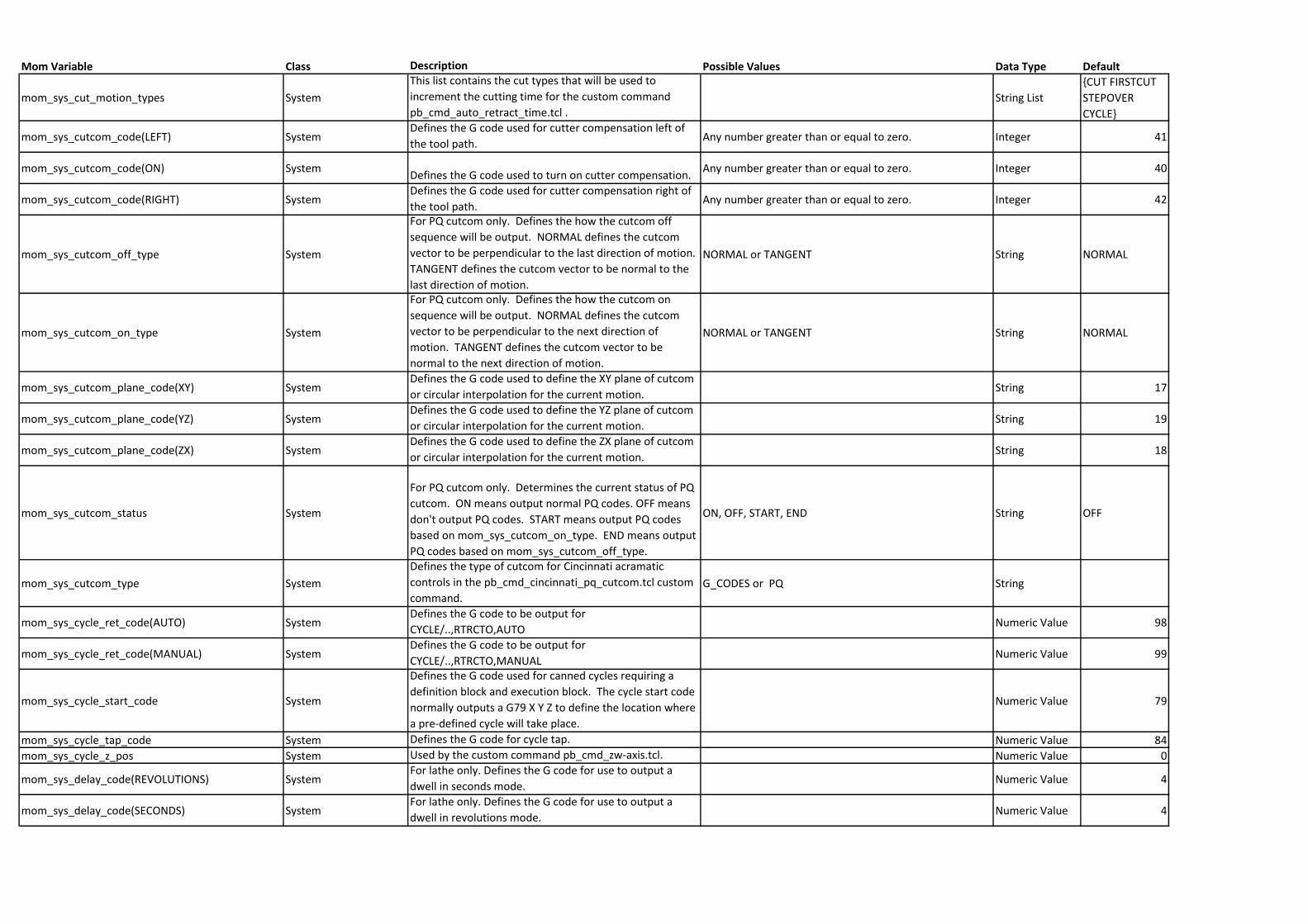
Mom Variable Class Description Possible Values Data Type Default
mom_sys_cut_motion_types System
This list contains the cut types that will be used to
increment the cutting time for the custom command
pb_cmd_auto_retract_time.tcl .String List
{CUT FIRSTCUT
STEPOVER
CYCLE}
mom_sys_cutcom_code(LEFT) SystemDefines the G code used for cutter compensation left of
the tool path.Any number greater than or equal to zero. Integer 41
mom_sys_cutcom_code(ON) SystemDefines the G code used to turn on cutter compensation.
Any number greater than or equal to zero. Integer 40
mom_sys_cutcom_code(RIGHT) SystemDefines the G code used for cutter compensation right of
the tool path.Any number greater than or equal to zero. Integer 42
mom_sys_cutcom_off_type System
For PQ cutcom only. Defines the how the cutcom off
sequence will be output. NORMAL defines the cutcom
vector to be perpendicular to the last direction of motion.
TANGENT defines the cutcom vector to be normal to the
last direction of motion.
NORMAL or TANGENT String NORMAL
mom_sys_cutcom_on_type System
For PQ cutcom only. Defines the how the cutcom on
sequence will be output. NORMAL defines the cutcom
vector to be perpendicular to the next direction of
motion. TANGENT defines the cutcom vector to be
normal to the next direction of motion.
NORMAL or TANGENT String NORMAL
mom_sys_cutcom_plane_code(XY) SystemDefines the G code used to define the XY plane of cutcom
or circular interpolation for the current motion.String 17
mom_sys_cutcom_plane_code(YZ) SystemDefines the G code used to define the YZ plane of cutcom
or circular interpolation for the current motion.String 19
mom_sys_cutcom_plane_code(ZX) SystemDefines the G code used to define the ZX plane of cutcom
or circular interpolation for the current motion.String 18
mom_sys_cutcom_status System
For PQ cutcom only. Determines the current status of PQ
cutcom. ON means output normal PQ codes. OFF means
don't output PQ codes. START means output PQ codes
based on mom_sys_cutcom_on_type. END means output
PQ codes based on mom_sys_cutcom_off_type.
ON, OFF, START, END String OFF
mom_sys_cutcom_type System
Defines the type of cutcom for Cincinnati acramatic
controls in the pb_cmd_cincinnati_pq_cutcom.tcl custom
command.G_CODES or PQ String
mom_sys_cycle_ret_code(AUTO) SystemDefines the G code to be output for
CYCLE/..,RTRCTO,AUTONumeric Value 98
mom_sys_cycle_ret_code(MANUAL) SystemDefines the G code to be output for
CYCLE/..,RTRCTO,MANUALNumeric Value 99
mom_sys_cycle_start_code System
Defines the G code used for canned cycles requiring a
definition block and execution block. The cycle start code
normally outputs a G79 X Y Z to define the location where
a pre-defined cycle will take place.
Numeric Value 79
mom_sys_cycle_tap_code System Defines the G code for cycle tap. Numeric Value 84
mom_sys_cycle_z_pos System Used by the custom command pb_cmd_zw-axis.tcl. Numeric Value 0
mom_sys_delay_code(REVOLUTIONS) SystemFor lathe only. Defines the G code for use to output a
dwell in seconds mode.Numeric Value 4
mom_sys_delay_code(SECONDS) SystemFor lathe only. Defines the G code for use to output a
dwell in revolutions mode.Numeric Value 4
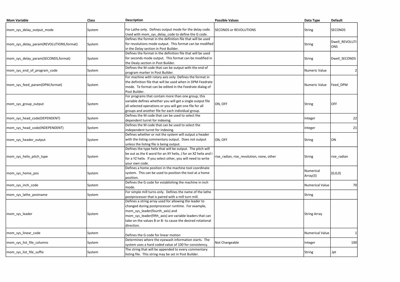
Mom Variable Class Description Possible Values Data Type Default
mom_sys_delay_output_mode System For Lathe only. Defines output mode for the delay code.
Used with mom_sys_delay_code to define the G code.SECONDS or REVOLUTIONS String SECONDS
mom_sys_delay_param(REVOLUTIONS,format) System
Defines the format in the definition file that will be used
for revolutions mode output. This format can be modified
in the Delay section in Post Builder.String
Dwell_REVOLUTI
ONS
mom_sys_delay_param(SECONDS,format) System
Defines the format in the definition file that will be used
for seconds mode output. This format can be modified in
the Dealy section in Post Builder.String Dwell_SECONDS
mom_sys_end_of_program_code SystemDefines the M code that can be output with the end of
program marker in Post Builder.Numeric Value 2
mom_sys_feed_param(DPM,format) System
For machine with rotary axis only. Defines the format in
the definition file that will be used when in DPM Feedrate
mode. Te format can be edited in the Feedrate dialog of
Post Builder.
Numeric Value Feed_DPM
mom_sys_group_output System
For programs that contain more than one group, this
variable defines whether you will get a single output file
all selected operations or you will get one file for all
groups and another file for each individual group.
ON, OFF String OFF
mom_sys_head_code(DEPENDENT) SystemDefines the M code that can be used to select the
dependent turret for indexing.Integer 22
mom_sys_head_code(INDEPENDENT) SystemDefines the M code that can be used to select the
independent turret for indexing.Integer 21
mom_sys_header_output System
Defines whether or not the system will output a header
with the listing commentary output. Does not output
unless the listing file is being output.ON, OFF String ON
mom_sys_helix_pitch_type System
Defines the type helix that will be output. The pitch will
be out as the K word for an XY helix, J for an XZ helix and I
for a YZ helix. If you select other, you will need to write
your own code.
rise_radian, rise_revolution, none, other String rise_radian
mom_sys_home_pos System
Defines a home position in the machine tool coordinate
system. This can be used to position the tool at a home
position.
Numerical
Array(3)(0,0,0)
mom_sys_inch_code SystemDefines the G code for establishing the machine in inch
mode.Numerical Value 70
mom_sys_lathe_postname SystemFor simple mill turns only. Defines the name of the lathe
postprocessor that is paired with a mill turn mill.String
mom_sys_leader System
Defines a string array used for allowing the leader to
changed during postprocessor runtime. For example,
mom_sys_leader(fourth_axis) and
mom_sys_leader(fifth_axis) are variable leaders that can
take on the values B or B- to cause the desired rotational
direction.
String Array
mom_sys_linear_code SystemDefines the G code for linear motion
Numerical Value 1
mom_sys_list_file_columns SystemDetermines where the eyewash information starts. The
system uses a hard coded value of 100 for consistency.Not Changeable Integer 100
mom_sys_list_file_suffix SystemThe string that will be appended to every commentary
listing file. This string may be set in Post Builder.String .lpt
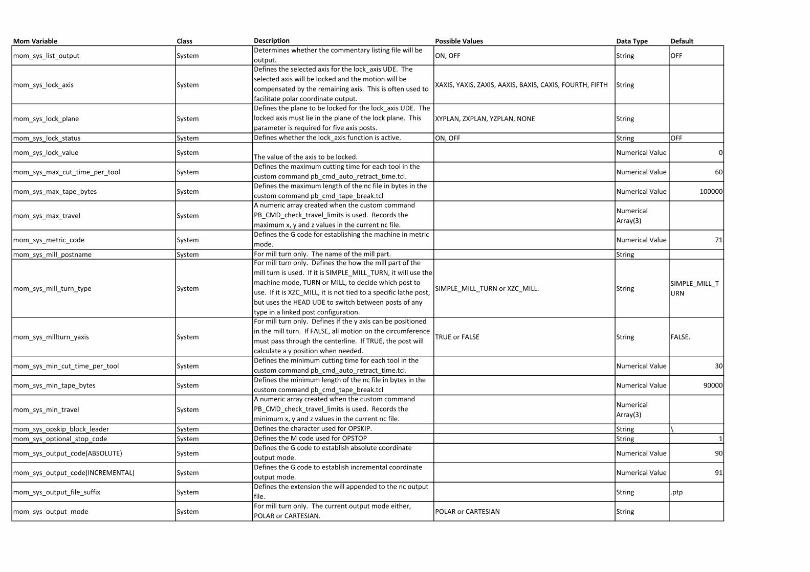
Mom Variable Class Description Possible Values Data Type Default
mom_sys_list_output SystemDetermines whether the commentary listing file will be
output.ON, OFF String OFF
mom_sys_lock_axis System
Defines the selected axis for the lock_axis UDE. The
selected axis will be locked and the motion will be
compensated by the remaining axis. This is often used to
facilitate polar coordinate output.
XAXIS, YAXIS, ZAXIS, AAXIS, BAXIS, CAXIS, FOURTH, FIFTH String
mom_sys_lock_plane System
Defines the plane to be locked for the lock_axis UDE. The
locked axis must lie in the plane of the lock plane. This
parameter is required for five axis posts.XYPLAN, ZXPLAN, YZPLAN, NONE String
mom_sys_lock_status System Defines whether the lock_axis function is active. ON, OFF String OFF
mom_sys_lock_value SystemThe value of the axis to be locked.
Numerical Value 0
mom_sys_max_cut_time_per_tool SystemDefines the maximum cutting time for each tool in the
custom command pb_cmd_auto_retract_time.tcl.Numerical Value 60
mom_sys_max_tape_bytes SystemDefines the maximum length of the nc file in bytes in the
custom command pb_cmd_tape_break.tclNumerical Value 100000
mom_sys_max_travel System
A numeric array created when the custom command
PB_CMD_check_travel_limits is used. Records the
maximum x, y and z values in the current nc file.
Numerical
Array(3)
mom_sys_metric_code SystemDefines the G code for establishing the machine in metric
mode.Numerical Value 71
mom_sys_mill_postname System For mill turn only. The name of the mill part. String
mom_sys_mill_turn_type System
For mill turn only. Defines the how the mill part of the
mill turn is used. If it is SIMPLE_MILL_TURN, it will use the
machine mode, TURN or MILL, to decide which post to
use. If it is XZC_MILL, it is not tied to a specific lathe post,
but uses the HEAD UDE to switch between posts of any
type in a linked post configuration.
SIMPLE_MILL_TURN or XZC_MILL. StringSIMPLE_MILL_T
URN
mom_sys_millturn_yaxis System
For mill turn only. Defines if the y axis can be positioned
in the mill turn. If FALSE, all motion on the circumference
must pass through the centerline. If TRUE, the post will
calculate a y position when needed.
TRUE or FALSE String FALSE.
mom_sys_min_cut_time_per_tool SystemDefines the minimum cutting time for each tool in the
custom command pb_cmd_auto_retract_time.tcl.Numerical Value 30
mom_sys_min_tape_bytes SystemDefines the minimum length of the nc file in bytes in the
custom command pb_cmd_tape_break.tclNumerical Value 90000
mom_sys_min_travel System
A numeric array created when the custom command
PB_CMD_check_travel_limits is used. Records the
minimum x, y and z values in the current nc file.
Numerical
Array(3)
mom_sys_opskip_block_leader System Defines the character used for OPSKIP. String \
mom_sys_optional_stop_code System Defines the M code used for OPSTOP String 1
mom_sys_output_code(ABSOLUTE) SystemDefines the G code to establish absolute coordinate
output mode.Numerical Value 90
mom_sys_output_code(INCREMENTAL) SystemDefines the G code to establish incremental coordinate
output mode.Numerical Value 91
mom_sys_output_file_suffix SystemDefines the extension the will appended to the nc output
file.String .ptp
mom_sys_output_mode SystemFor mill turn only. The current output mode either,
POLAR or CARTESIAN.POLAR or CARTESIAN String
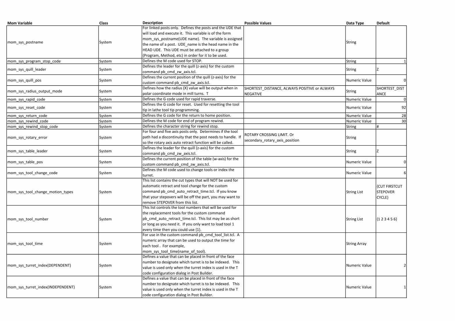
Mom Variable Class Description Possible Values Data Type Default
mom_sys_postname System
For linked posts only. Defines the posts and the UDE that
will load and execute it. This variable is of the form
mom_sys_postname(UDE name). The variable is assigned
the name of a post. UDE_name is the head name in the
HEAD UDE. This UDE must be attached to a group
(Program, Method, etc) in order for it to be used.
String
mom_sys_program_stop_code System Defines the M code used for STOP. String 1
mom_sys_quill_leader SystemDefines the leader for the quill (z-axis) for the custom
command pb_cmd_zw_axis.tcl.String Z
mom_sys_quill_pos SystemDefines the current position of the quill (z-axis) for the
custom command pb_cmd_zw_axis.tcl.Numeric Value 0
mom_sys_radius_output_mode SystemDefines how the radius (X) value will be output when in
polar coordinate mode in mill turns. TSHORTEST_DISTANCE, ALWAYS POSITIVE or ALWAYS
NEGATIVEString
SHORTEST_DIST
ANCE
mom_sys_rapid_code System Defines the G code used for rapid traverse. Numeric Value 0
mom_sys_reset_code SystemDefines the G code for reset. Used for resetting the tool
tip in lathe tool tip programming.Numeric Value 92
mom_sys_return_code System Defines the G code for the return to home position. Numeric Value 28
mom_sys_rewind_code System Defines the M code for end of program rewind. Numeric Value 30
mom_sys_rewind_stop_code System Defines the character string for rewind stop. String #
mom_sys_rotary_error System
For four and five axis posts only. Determines if the tool
path had a discontinuity that the post needs to handle. If
so the rotary axis auto retract function will be called.
ROTARY CROSSING LIMIT. Or
secondary_rotary_axis_positionString
mom_sys_table_leader SystemDefines the leader for the quill (z-axis) for the custom
command pb_cmd_zw_axis.tcl.String Z
mom_sys_table_pos SystemDefines the current position of the table (w-axis) for the
custom command pb_cmd_zw_axis.tcl.Numeric Value 0
mom_sys_tool_change_code SystemDefines the M code used to change tools or index the
turret.Numeric Value 6
mom_sys_tool_change_motion_types System
This list contains the cut types that will NOT be used for
automatic retract and tool change for the custom
command pb_cmd_auto_retract_time.tcl. If you know
that your stepovers will be off the part, you may want to
remove STEPOVER from this list.
String List
{CUT FIRSTCUT
STEPOVER
CYCLE}
mom_sys_tool_number System
This list controls the tool numbers that will be used for
the replacement tools for the custom command
pb_cmd_auto_retract_time.tcl. This list may be as short
or long as you need it. If you only want to load tool 1
every time then you could use {1}.
String List {1 2 3 4 5 6}
mom_sys_tool_time System
For use in the custom command pb_cmd_tool_list.tcl. A
numeric array that can be used to output the time for
each tool . For example,
mom_sys_tool_time(name_of_tool).
String Array
mom_sys_turret_index(DEPENDENT) System
Defines a value that can be placed in front of the face
number to designate which turret is to be indexed. This
value is used only when the turret index is used in the T
code configuration dialog in Post Builder.
Numeric Value 2
mom_sys_turret_index(INDEPENDENT) System
Defines a value that can be placed in front of the face
number to designate which turret is to be indexed. This
value is used only when the turret index is used in the T
code configuration dialog in Post Builder.
Numeric Value 1
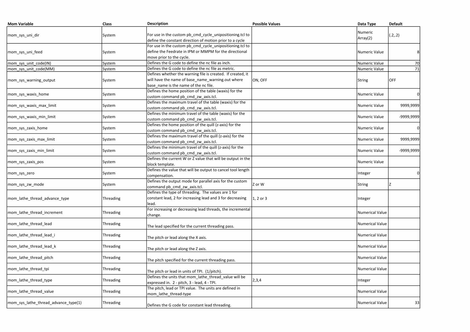
Mom Variable Class Description Possible Values Data Type Default
mom_sys_uni_dir System For use in the custom pb_cmd_cycle_unipositioning.tcl to
define the constant direction of motion prior to a cycle
Numeric
Array(2)(.2,.2)
mom_sys_uni_feed System
For use in the custom pb_cmd_cycle_unipositioning.tcl to
define the Feedrate in IPM or MMPM for the directional
move prior to the cycle. Numeric Value 8
mom_sys_unit_code(IN) System Defines the G code to define the nc file as inch. Numeric Value 70
mom_sys_unit_code(MM) System Defines the G code to define the nc file as metric. Numeric Value 71
mom_sys_warning_output System
Defines whether the warning file is created. If created, it
will have the name of base_name_warning.out where
base_name is the name of the nc file.ON, OFF String OFF
mom_sys_waxis_home SystemDefines the home position of the table (waxis) for the
custom command pb_cmd_zw_axis.tcl.Numeric Value 0
mom_sys_waxis_max_limit SystemDefines the maximum travel of the table (waxis) for the
custom command pb_cmd_zw_axis.tcl.Numeric Value 9999,9999
mom_sys_waxis_min_limit SystemDefines the minimum travel of the table (waxis) for the
custom command pb_cmd_zw_axis.tcl.Numeric Value -9999,9999
mom_sys_zaxis_home SystemDefines the home position of the quill (z-axis) for the
custom command pb_cmd_zw_axis.tcl.Numeric Value 0
mom_sys_zaxis_max_limit SystemDefines the maximum travel of the quill (z-axis) for the
custom command pb_cmd_zw_axis.tcl.Numeric Value 9999,9999
mom_sys_zaxis_min_limit SystemDefines the minimum travel of the quill (z-axis) for the
custom command pb_cmd_zw_axis.tcl.Numeric Value -9999,9999
mom_sys_zaxis_pos SystemDefines the current W or Z value that will be output in the
block template.Numeric Value
mom_sys_zero SystemDefines the value that will be output to cancel tool length
compensation.Integer 0
mom_sys_zw_mode SystemDefines the output mode for parallel axis for the custom
command pb_cmd_zw_axis.tcl.Z or W String Z
mom_lathe_thread_advance_type Threading
Defines the type of threading. The values are 1 for
constant lead, 2 for increasing lead and 3 for decreasing
lead.1, 2 or 3 Integer
mom_lathe_thread_increment ThreadingFor increasing or decreasing lead threads, the incremental
change.Numerical Value
mom_lathe_thread_lead ThreadingThe lead specified for the current threading pass.
Numerical Value
mom_lathe_thread_lead_i ThreadingThe pitch or lead along the X axis.
Numerical Value
mom_lathe_thread_lead_k ThreadingThe pitch or lead along the Z axis.
Numerical Value
mom_lathe_thread_pitch ThreadingThe pitch specified for the current threading pass.
Numerical Value
mom_lathe_thread_tpi ThreadingThe pitch or lead in units of TPI. (1/pitch).
Numerical Value
mom_lathe_thread_type ThreadingDefines the units that mom_lathe_thread_value will be
expressed in. 2 - pitch, 3 - lead, 4 - TPI.2,3,4 Integer
mom_lathe_thread_value ThreadingThe pitch, lead or TPI value. The units are defined in
mom_lathe_thread-typeNumerical Value
mom_sys_lathe_thread_advance_type(1) ThreadingDefines the G code for constant lead threading.
Numerical Value 33
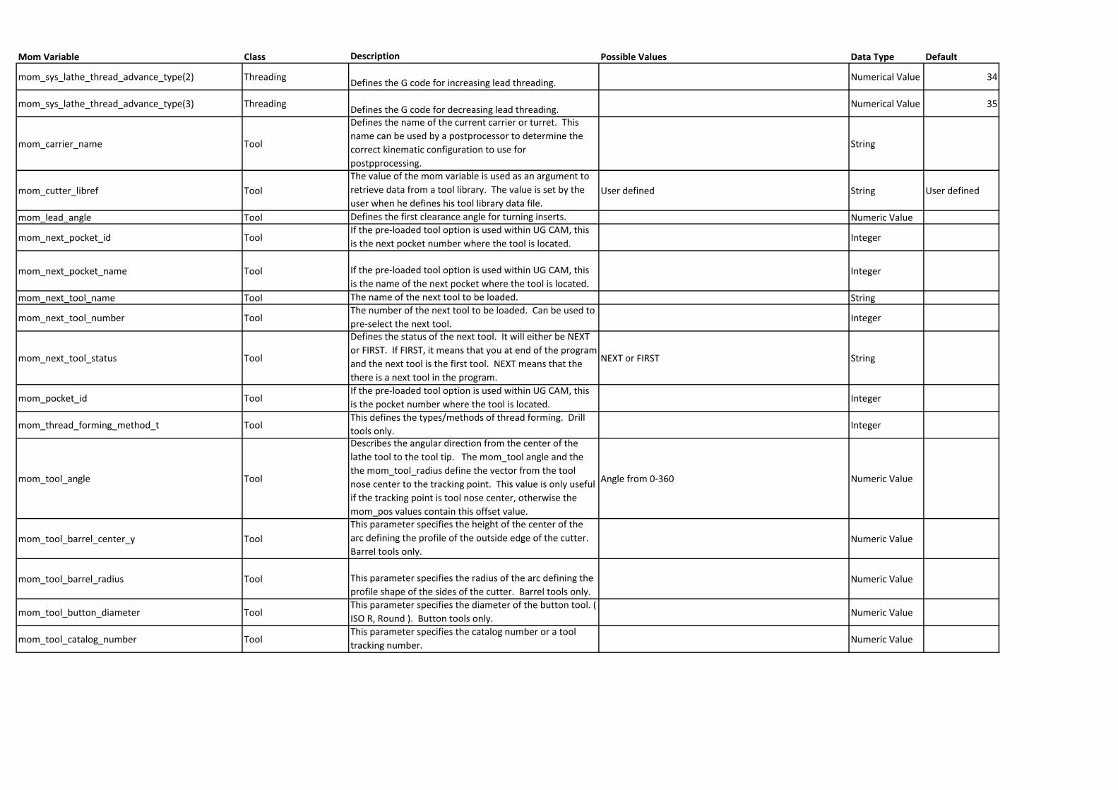
Mom Variable Class Description Possible Values Data Type Default
mom_sys_lathe_thread_advance_type(2) ThreadingDefines the G code for increasing lead threading.
Numerical Value 34
mom_sys_lathe_thread_advance_type(3) ThreadingDefines the G code for decreasing lead threading.
Numerical Value 35
mom_carrier_name Tool
Defines the name of the current carrier or turret. This
name can be used by a postprocessor to determine the
correct kinematic configuration to use for
postpprocessing.
String
mom_cutter_libref Tool
The value of the mom variable is used as an argument to
retrieve data from a tool library. The value is set by the
user when he defines his tool library data file.User defined String User defined
mom_lead_angle Tool Defines the first clearance angle for turning inserts. Numeric Value
mom_next_pocket_id ToolIf the pre-loaded tool option is used within UG CAM, this
is the next pocket number where the tool is located.Integer
mom_next_pocket_name Tool If the pre-loaded tool option is used within UG CAM, this
is the name of the next pocket where the tool is located.Integer
mom_next_tool_name Tool The name of the next tool to be loaded. String
mom_next_tool_number ToolThe number of the next tool to be loaded. Can be used to
pre-select the next tool.Integer
mom_next_tool_status Tool
Defines the status of the next tool. It will either be NEXT
or FIRST. If FIRST, it means that you at end of the program
and the next tool is the first tool. NEXT means that the
there is a next tool in the program.
NEXT or FIRST String
mom_pocket_id ToolIf the pre-loaded tool option is used within UG CAM, this
is the pocket number where the tool is located.Integer
mom_thread_forming_method_t ToolThis defines the types/methods of thread forming. Drill
tools only.Integer
mom_tool_angle Tool
Describes the angular direction from the center of the
lathe tool to the tool tip. The mom_tool angle and the
the mom_tool_radius define the vector from the tool
nose center to the tracking point. This value is only useful
if the tracking point is tool nose center, otherwise the
mom_pos values contain this offset value.
Angle from 0-360 Numeric Value
mom_tool_barrel_center_y Tool
This parameter specifies the height of the center of the
arc defining the profile of the outside edge of the cutter.
Barrel tools only.Numeric Value
mom_tool_barrel_radius Tool This parameter specifies the radius of the arc defining the
profile shape of the sides of the cutter. Barrel tools only.Numeric Value
mom_tool_button_diameter ToolThis parameter specifies the diameter of the button tool. (
ISO R, Round ). Button tools only.Numeric Value
mom_tool_catalog_number ToolThis parameter specifies the catalog number or a tool
tracking number.Numeric Value
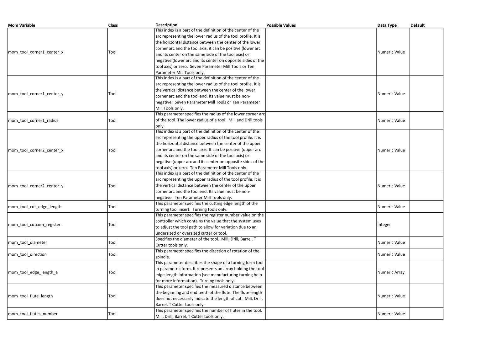
Mom Variable Class Description Possible Values Data Type Default
mom_tool_corner1_center_x Tool
This index is a part of the definition of the center of the
arc representing the lower radius of the tool profile. It is
the horizontal distance between the center of the lower
corner arc and the tool axis; it can be positive (lower arc
and its center on the same side of the tool axis) or
negative (lower arc and its center on opposite sides of the
tool axis) or zero. Seven Parameter Mill Tools or Ten
Parameter Mill Tools only.
Numeric Value
mom_tool_corner1_center_y Tool
This index is a part of the definition of the center of the
arc representing the lower radius of the tool profile. It is
the vertical distance between the center of the lower
corner arc and the tool end. Its value must be non-
negative. Seven Parameter Mill Tools or Ten Parameter
Mill Tools only.
Numeric Value
mom_tool_corner1_radius Tool
This parameter specifies the radius of the lower corner arc
of the tool. The lower radius of a tool. Mill and Drill tools
only.Numeric Value
mom_tool_corner2_center_x Tool
This index is a part of the definition of the center of the
arc representing the upper radius of the tool profile. It is
the horizontal distance between the center of the upper
corner arc and the tool axis. It can be positive (upper arc
and its center on the same side of the tool axis) or
negative (upper arc and its center on opposite sides of the
tool axis) or zero. Ten Parameter Mill Tools only.
Numeric Value
mom_tool_corner2_center_y Tool
This index is a part of the definition of the center of the
arc representing the upper radius of the tool profile. It is
the vertical distance between the center of the upper
corner arc and the tool end. Its value must be non-
negative. Ten Parameter Mill Tools only.
Numeric Value
mom_tool_cut_edge_length ToolThis parameter specifies the cutting edge length of the
turning tool insert. Turning tools only.Numeric Value
mom_tool_cutcom_register Tool
This parameter specifies the register number value on the
controller which contains the value that the system uses
to adjust the tool path to allow for variation due to an
undersized or oversized cutter or tool.
Integer
mom_tool_diameter ToolSpecifies the diameter of the tool. Mill, Drill, Barrel, T
Cutter tools only.Numeric Value
mom_tool_direction ToolThis parameter specifies the direction of rotation of the
spindle.Numeric Value
mom_tool_edge_length_a Tool
This parameter describes the shape of a turning form tool
in parametric form. It represents an array holding the tool
edge length information (see manufacturing turning help
for more information). Turning tools only.
Numeric Array
mom_tool_flute_length Tool
This parameter specifies the measured distance between
the beginning and end teeth of the flute. The flute length
does not necessarily indicate the length of cut. Mill, Drill,
Barrel, T Cutter tools only.
Numeric Value
mom_tool_flutes_number ToolThis parameter specifies the number of flutes in the tool.
Mill, Drill, Barrel, T Cutter tools only.Numeric Value
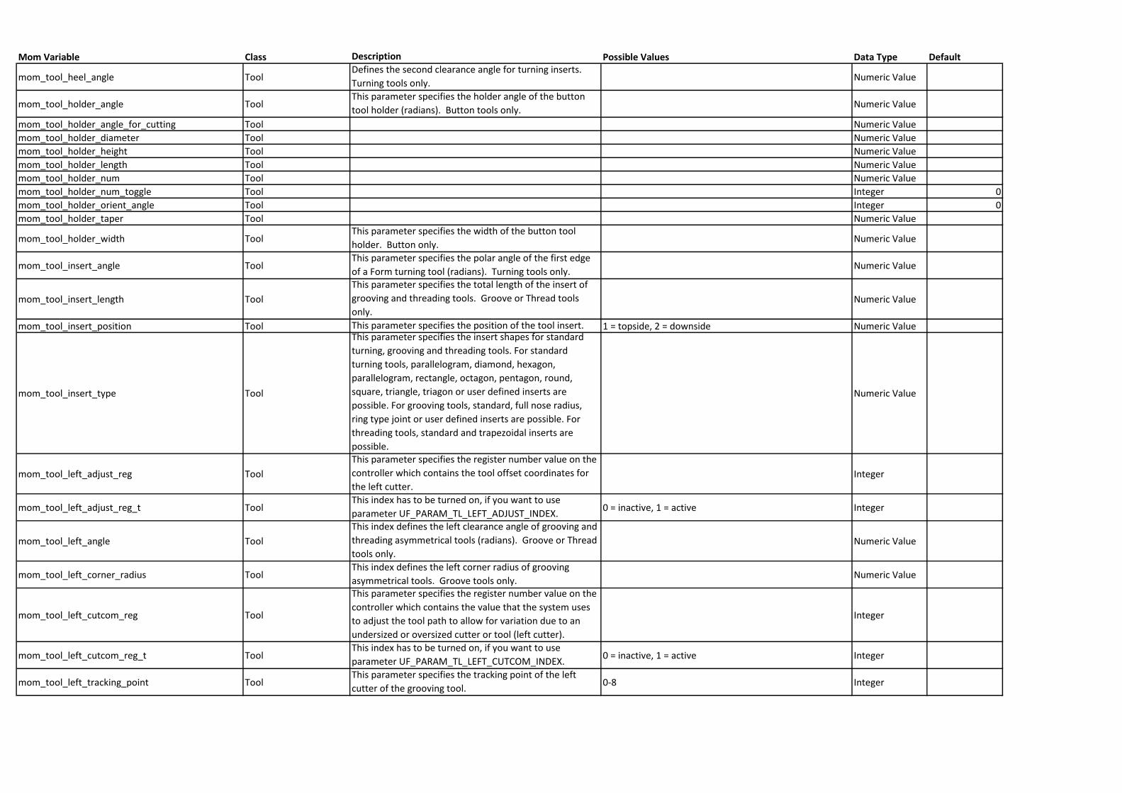
Mom Variable Class Description Possible Values Data Type Default
mom_tool_heel_angle ToolDefines the second clearance angle for turning inserts.
Turning tools only.Numeric Value
mom_tool_holder_angle ToolThis parameter specifies the holder angle of the button
tool holder (radians). Button tools only.Numeric Value
mom_tool_holder_angle_for_cutting Tool Numeric Value
mom_tool_holder_diameter Tool Numeric Value
mom_tool_holder_height Tool Numeric Value
mom_tool_holder_length Tool Numeric Value
mom_tool_holder_num Tool Numeric Value
mom_tool_holder_num_toggle Tool Integer 0
mom_tool_holder_orient_angle Tool Integer 0
mom_tool_holder_taper Tool Numeric Value
mom_tool_holder_width ToolThis parameter specifies the width of the button tool
holder. Button only.Numeric Value
mom_tool_insert_angle ToolThis parameter specifies the polar angle of the first edge
of a Form turning tool (radians). Turning tools only.Numeric Value
mom_tool_insert_length Tool
This parameter specifies the total length of the insert of
grooving and threading tools. Groove or Thread tools
only.Numeric Value
mom_tool_insert_position Tool This parameter specifies the position of the tool insert. 1 = topside, 2 = downside Numeric Value
mom_tool_insert_type Tool
This parameter specifies the insert shapes for standard
turning, grooving and threading tools. For standard
turning tools, parallelogram, diamond, hexagon,
parallelogram, rectangle, octagon, pentagon, round,
square, triangle, triagon or user defined inserts are
possible. For grooving tools, standard, full nose radius,
ring type joint or user defined inserts are possible. For
threading tools, standard and trapezoidal inserts are
possible.
Numeric Value
mom_tool_left_adjust_reg Tool
This parameter specifies the register number value on the
controller which contains the tool offset coordinates for
the left cutter.Integer
mom_tool_left_adjust_reg_t ToolThis index has to be turned on, if you want to use
parameter UF_PARAM_TL_LEFT_ADJUST_INDEX.0 = inactive, 1 = active Integer
mom_tool_left_angle Tool
This index defines the left clearance angle of grooving and
threading asymmetrical tools (radians). Groove or Thread
tools only.Numeric Value
mom_tool_left_corner_radius ToolThis index defines the left corner radius of grooving
asymmetrical tools. Groove tools only.Numeric Value
mom_tool_left_cutcom_reg Tool
This parameter specifies the register number value on the
controller which contains the value that the system uses
to adjust the tool path to allow for variation due to an
undersized or oversized cutter or tool (left cutter).
Integer
mom_tool_left_cutcom_reg_t ToolThis index has to be turned on, if you want to use
parameter UF_PARAM_TL_LEFT_CUTCOM_INDEX.0 = inactive, 1 = active Integer
mom_tool_left_tracking_point ToolThis parameter specifies the tracking point of the left
cutter of the grooving tool.0-8 Integer
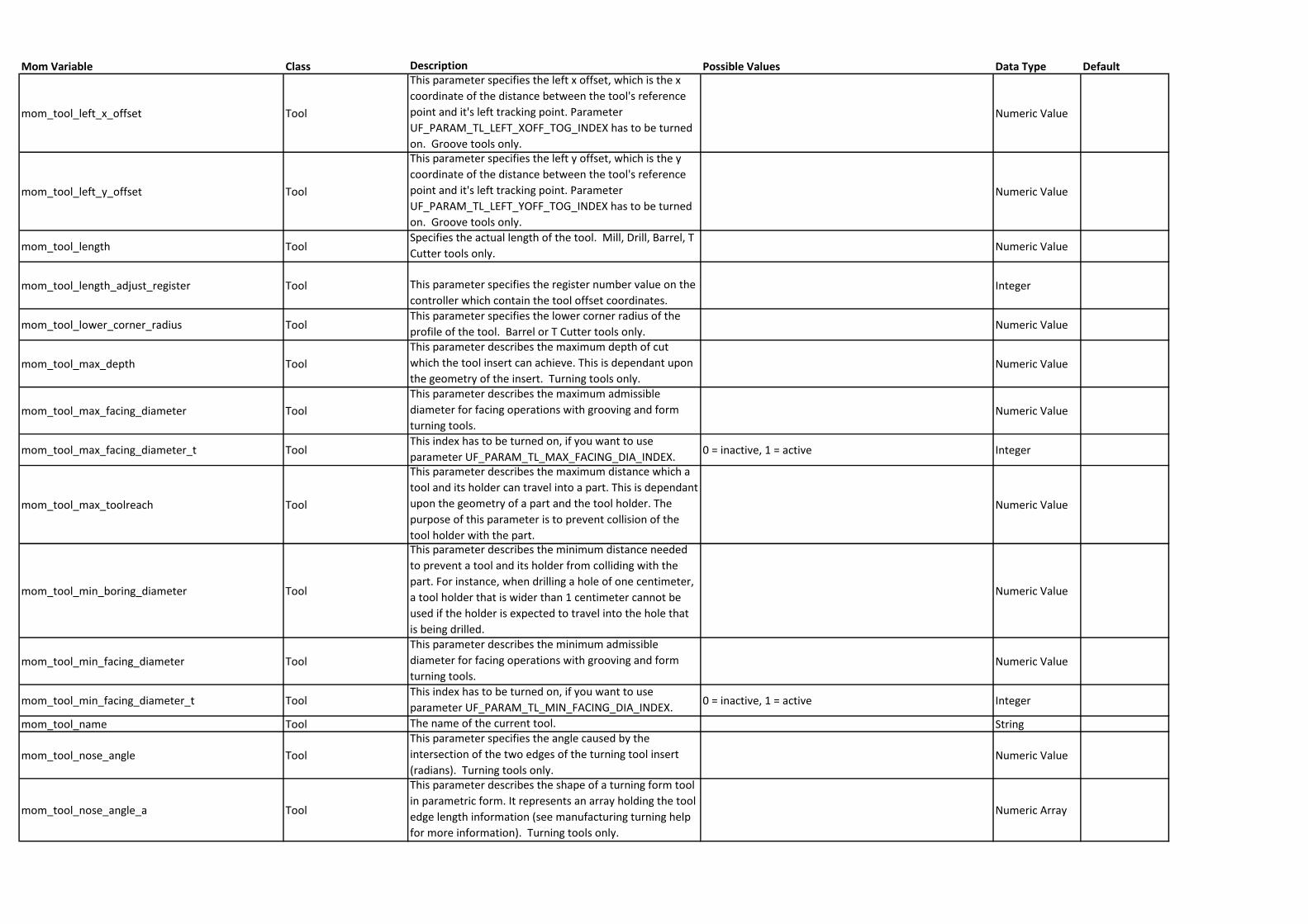
Mom Variable Class Description Possible Values Data Type Default
mom_tool_left_x_offset Tool
This parameter specifies the left x offset, which is the x
coordinate of the distance between the tool's reference
point and it's left tracking point. Parameter
UF_PARAM_TL_LEFT_XOFF_TOG_INDEX has to be turned
on. Groove tools only.
Numeric Value
mom_tool_left_y_offset Tool
This parameter specifies the left y offset, which is the y
coordinate of the distance between the tool's reference
point and it's left tracking point. Parameter
UF_PARAM_TL_LEFT_YOFF_TOG_INDEX has to be turned
on. Groove tools only.
Numeric Value
mom_tool_length ToolSpecifies the actual length of the tool. Mill, Drill, Barrel, T
Cutter tools only.Numeric Value
mom_tool_length_adjust_register Tool This parameter specifies the register number value on the
controller which contain the tool offset coordinates.Integer
mom_tool_lower_corner_radius ToolThis parameter specifies the lower corner radius of the
profile of the tool. Barrel or T Cutter tools only.Numeric Value
mom_tool_max_depth Tool
This parameter describes the maximum depth of cut
which the tool insert can achieve. This is dependant upon
the geometry of the insert. Turning tools only.Numeric Value
mom_tool_max_facing_diameter Tool
This parameter describes the maximum admissible
diameter for facing operations with grooving and form
turning tools.Numeric Value
mom_tool_max_facing_diameter_t ToolThis index has to be turned on, if you want to use
parameter UF_PARAM_TL_MAX_FACING_DIA_INDEX.0 = inactive, 1 = active Integer
mom_tool_max_toolreach Tool
This parameter describes the maximum distance which a
tool and its holder can travel into a part. This is dependant
upon the geometry of a part and the tool holder. The
purpose of this parameter is to prevent collision of the
tool holder with the part.
Numeric Value
mom_tool_min_boring_diameter Tool
This parameter describes the minimum distance needed
to prevent a tool and its holder from colliding with the
part. For instance, when drilling a hole of one centimeter,
a tool holder that is wider than 1 centimeter cannot be
used if the holder is expected to travel into the hole that
is being drilled.
Numeric Value
mom_tool_min_facing_diameter Tool
This parameter describes the minimum admissible
diameter for facing operations with grooving and form
turning tools.Numeric Value
mom_tool_min_facing_diameter_t ToolThis index has to be turned on, if you want to use
parameter UF_PARAM_TL_MIN_FACING_DIA_INDEX.0 = inactive, 1 = active Integer
mom_tool_name Tool The name of the current tool. String
mom_tool_nose_angle Tool
This parameter specifies the angle caused by the
intersection of the two edges of the turning tool insert
(radians). Turning tools only.Numeric Value
mom_tool_nose_angle_a Tool
This parameter describes the shape of a turning form tool
in parametric form. It represents an array holding the tool
edge length information (see manufacturing turning help
for more information). Turning tools only.
Numeric Array
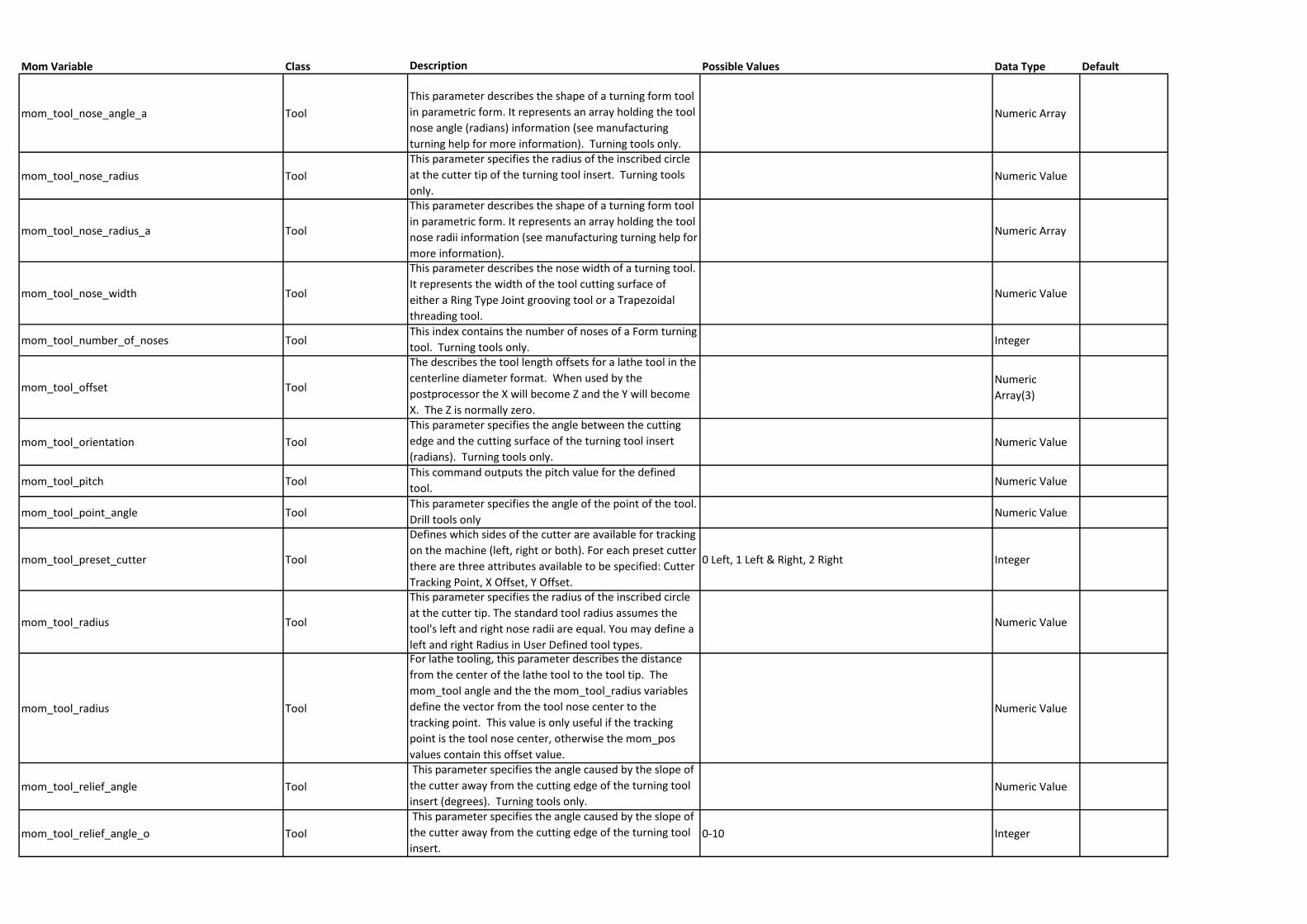
Mom Variable Class Description Possible Values Data Type Default
mom_tool_nose_angle_a Tool
This parameter describes the shape of a turning form tool
in parametric form. It represents an array holding the tool
nose angle (radians) information (see manufacturing
turning help for more information). Turning tools only.
Numeric Array
mom_tool_nose_radius Tool
This parameter specifies the radius of the inscribed circle
at the cutter tip of the turning tool insert. Turning tools
only.Numeric Value
mom_tool_nose_radius_a Tool
This parameter describes the shape of a turning form tool
in parametric form. It represents an array holding the tool
nose radii information (see manufacturing turning help for
more information).
Numeric Array
mom_tool_nose_width Tool
This parameter describes the nose width of a turning tool.
It represents the width of the tool cutting surface of
either a Ring Type Joint grooving tool or a Trapezoidal
threading tool.
Numeric Value
mom_tool_number_of_noses ToolThis index contains the number of noses of a Form turning
tool. Turning tools only.Integer
mom_tool_offset Tool
The describes the tool length offsets for a lathe tool in the
centerline diameter format. When used by the
postprocessor the X will become Z and the Y will become
X. The Z is normally zero.
Numeric
Array(3)
mom_tool_orientation Tool
This parameter specifies the angle between the cutting
edge and the cutting surface of the turning tool insert
(radians). Turning tools only.Numeric Value
mom_tool_pitch ToolThis command outputs the pitch value for the defined
tool.Numeric Value
mom_tool_point_angle ToolThis parameter specifies the angle of the point of the tool.
Drill tools onlyNumeric Value
mom_tool_preset_cutter Tool
Defines which sides of the cutter are available for tracking
on the machine (left, right or both). For each preset cutter
there are three attributes available to be specified: Cutter
Tracking Point, X Offset, Y Offset.
0 Left, 1 Left & Right, 2 Right Integer
mom_tool_radius Tool
This parameter specifies the radius of the inscribed circle
at the cutter tip. The standard tool radius assumes the
tool's left and right nose radii are equal. You may define a
left and right Radius in User Defined tool types.
Numeric Value
mom_tool_radius Tool
For lathe tooling, this parameter describes the distance
from the center of the lathe tool to the tool tip. The
mom_tool angle and the the mom_tool_radius variables
define the vector from the tool nose center to the
tracking point. This value is only useful if the tracking
point is the tool nose center, otherwise the mom_pos
values contain this offset value.
Numeric Value
mom_tool_relief_angle Tool
This parameter specifies the angle caused by the slope of
the cutter away from the cutting edge of the turning tool
insert (degrees). Turning tools only.Numeric Value
mom_tool_relief_angle_o Tool
This parameter specifies the angle caused by the slope of
the cutter away from the cutting edge of the turning tool
insert.0-10 Integer
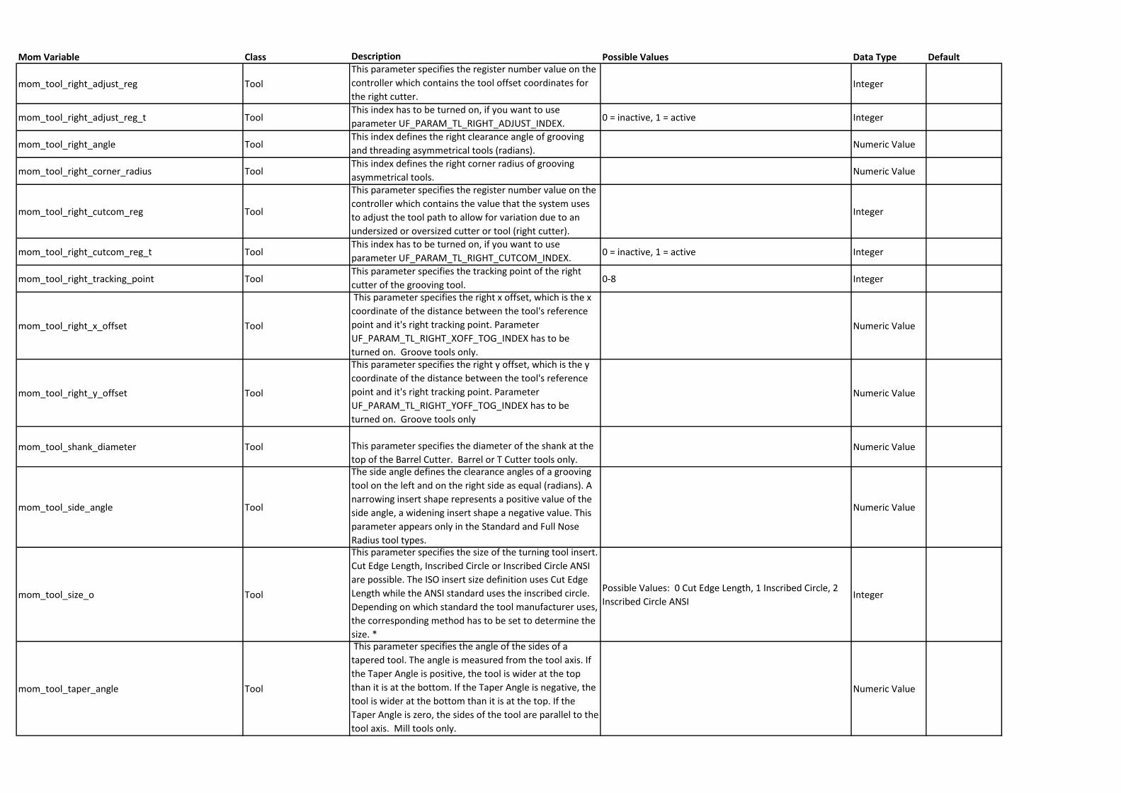
Mom Variable Class Description Possible Values Data Type Default
mom_tool_right_adjust_reg Tool
This parameter specifies the register number value on the
controller which contains the tool offset coordinates for
the right cutter.Integer
mom_tool_right_adjust_reg_t ToolThis index has to be turned on, if you want to use
parameter UF_PARAM_TL_RIGHT_ADJUST_INDEX.0 = inactive, 1 = active Integer
mom_tool_right_angle ToolThis index defines the right clearance angle of grooving
and threading asymmetrical tools (radians).Numeric Value
mom_tool_right_corner_radius ToolThis index defines the right corner radius of grooving
asymmetrical tools.Numeric Value
mom_tool_right_cutcom_reg Tool
This parameter specifies the register number value on the
controller which contains the value that the system uses
to adjust the tool path to allow for variation due to an
undersized or oversized cutter or tool (right cutter).
Integer
mom_tool_right_cutcom_reg_t ToolThis index has to be turned on, if you want to use
parameter UF_PARAM_TL_RIGHT_CUTCOM_INDEX.0 = inactive, 1 = active Integer
mom_tool_right_tracking_point ToolThis parameter specifies the tracking point of the right
cutter of the grooving tool.0-8 Integer
mom_tool_right_x_offset Tool
This parameter specifies the right x offset, which is the x
coordinate of the distance between the tool's reference
point and it's right tracking point. Parameter
UF_PARAM_TL_RIGHT_XOFF_TOG_INDEX has to be
turned on. Groove tools only.
Numeric Value
mom_tool_right_y_offset Tool
This parameter specifies the right y offset, which is the y
coordinate of the distance between the tool's reference
point and it's right tracking point. Parameter
UF_PARAM_TL_RIGHT_YOFF_TOG_INDEX has to be
turned on. Groove tools only
Numeric Value
mom_tool_shank_diameter Tool This parameter specifies the diameter of the shank at the
top of the Barrel Cutter. Barrel or T Cutter tools only.Numeric Value
mom_tool_side_angle Tool
The side angle defines the clearance angles of a grooving
tool on the left and on the right side as equal (radians). A
narrowing insert shape represents a positive value of the
side angle, a widening insert shape a negative value. This
parameter appears only in the Standard and Full Nose
Radius tool types.
Numeric Value
mom_tool_size_o Tool
This parameter specifies the size of the turning tool insert.
Cut Edge Length, Inscribed Circle or Inscribed Circle ANSI
are possible. The ISO insert size definition uses Cut Edge
Length while the ANSI standard uses the inscribed circle.
Depending on which standard the tool manufacturer uses,
the corresponding method has to be set to determine the
size. *
Possible Values: 0 Cut Edge Length, 1 Inscribed Circle, 2
Inscribed Circle ANSIInteger
mom_tool_taper_angle Tool
This parameter specifies the angle of the sides of a
tapered tool. The angle is measured from the tool axis. If
the Taper Angle is positive, the tool is wider at the top
than it is at the bottom. If the Taper Angle is negative, the
tool is wider at the bottom than it is at the top. If the
Taper Angle is zero, the sides of the tool are parallel to the
tool axis. Mill tools only.
Numeric Value
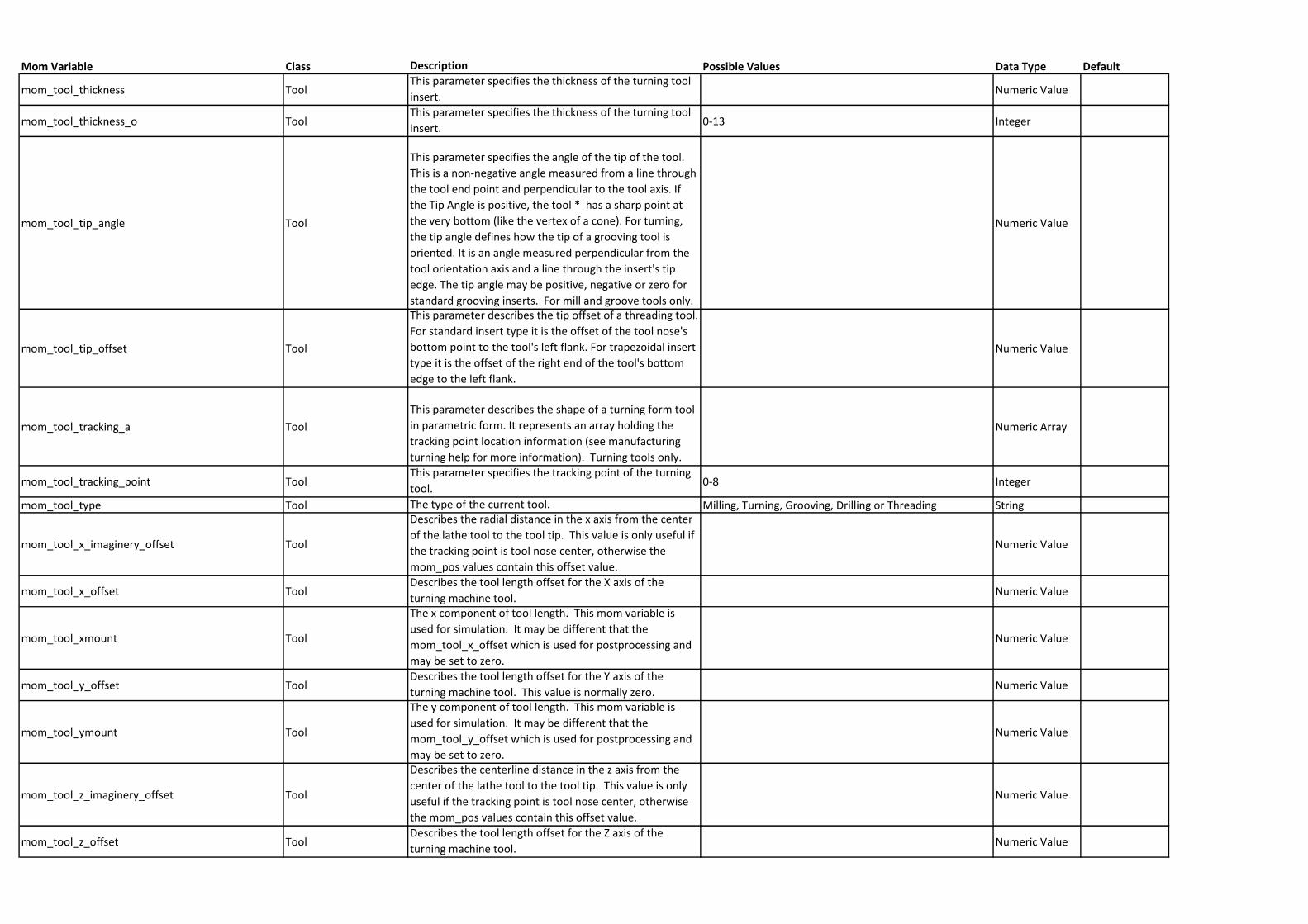
Mom Variable Class Description Possible Values Data Type Default
mom_tool_thickness ToolThis parameter specifies the thickness of the turning tool
insert.Numeric Value
mom_tool_thickness_o ToolThis parameter specifies the thickness of the turning tool
insert.0-13 Integer
mom_tool_tip_angle Tool
This parameter specifies the angle of the tip of the tool.
This is a non-negative angle measured from a line through
the tool end point and perpendicular to the tool axis. If
the Tip Angle is positive, the tool * has a sharp point at
the very bottom (like the vertex of a cone). For turning,
the tip angle defines how the tip of a grooving tool is
oriented. It is an angle measured perpendicular from the
tool orientation axis and a line through the insert's tip
edge. The tip angle may be positive, negative or zero for
standard grooving inserts. For mill and groove tools only.
Numeric Value
mom_tool_tip_offset Tool
This parameter describes the tip offset of a threading tool.
For standard insert type it is the offset of the tool nose's
bottom point to the tool's left flank. For trapezoidal insert
type it is the offset of the right end of the tool's bottom
edge to the left flank.
Numeric Value
mom_tool_tracking_a Tool
This parameter describes the shape of a turning form tool
in parametric form. It represents an array holding the
tracking point location information (see manufacturing
turning help for more information). Turning tools only.
Numeric Array
mom_tool_tracking_point ToolThis parameter specifies the tracking point of the turning
tool.0-8 Integer
mom_tool_type Tool The type of the current tool. Milling, Turning, Grooving, Drilling or Threading String
mom_tool_x_imaginery_offset Tool
Describes the radial distance in the x axis from the center
of the lathe tool to the tool tip. This value is only useful if
the tracking point is tool nose center, otherwise the
mom_pos values contain this offset value.
Numeric Value
mom_tool_x_offset ToolDescribes the tool length offset for the X axis of the
turning machine tool.Numeric Value
mom_tool_xmount Tool
The x component of tool length. This mom variable is
used for simulation. It may be different that the
mom_tool_x_offset which is used for postprocessing and
may be set to zero.
Numeric Value
mom_tool_y_offset ToolDescribes the tool length offset for the Y axis of the
turning machine tool. This value is normally zero.Numeric Value
mom_tool_ymount Tool
The y component of tool length. This mom variable is
used for simulation. It may be different that the
mom_tool_y_offset which is used for postprocessing and
may be set to zero.
Numeric Value
mom_tool_z_imaginery_offset Tool
Describes the centerline distance in the z axis from the
center of the lathe tool to the tool tip. This value is only
useful if the tracking point is tool nose center, otherwise
the mom_pos values contain this offset value.
Numeric Value
mom_tool_z_offset ToolDescribes the tool length offset for the Z axis of the
turning machine tool.Numeric Value
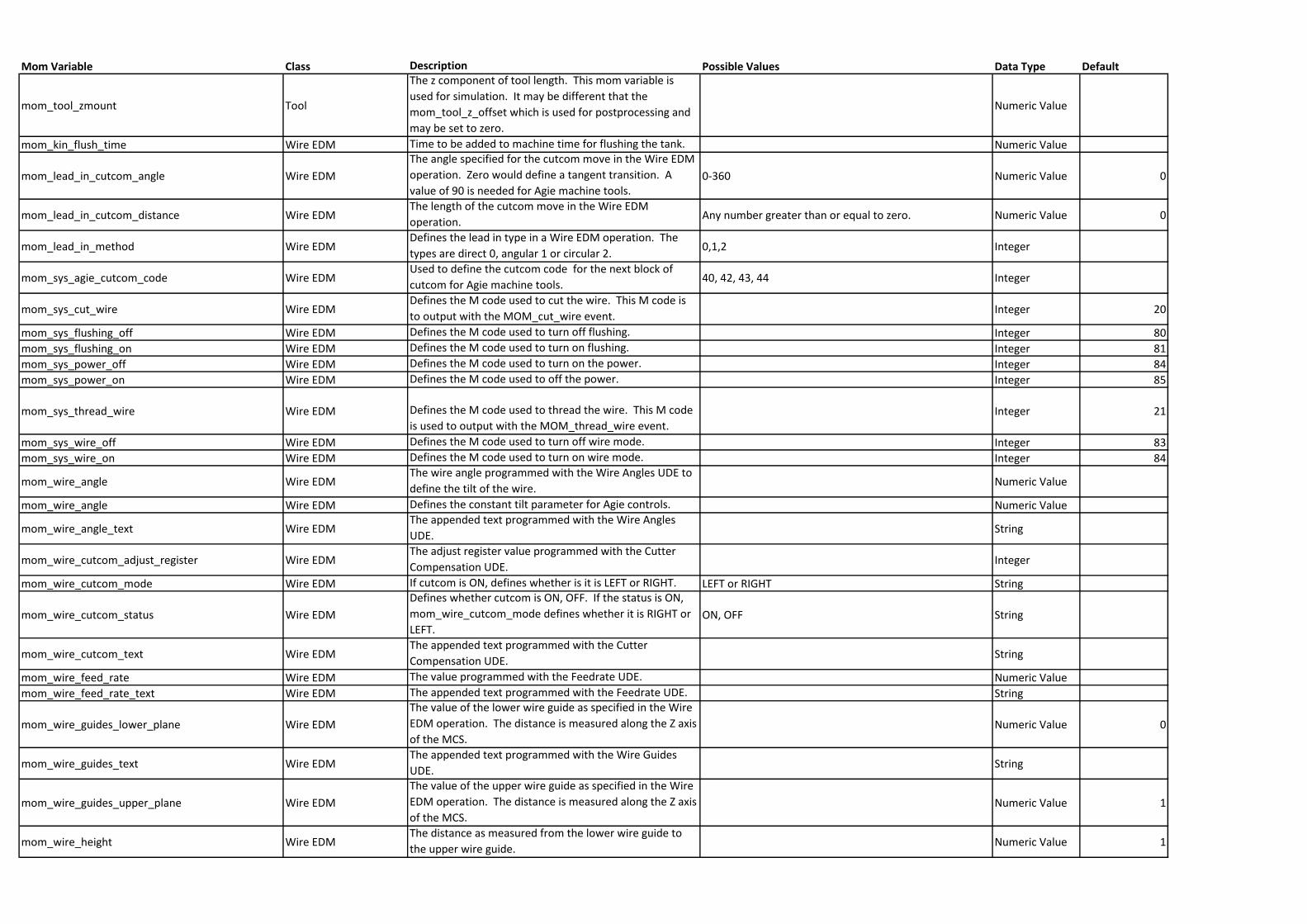
Mom Variable Class Description Possible Values Data Type Default
mom_tool_zmount Tool
The z component of tool length. This mom variable is
used for simulation. It may be different that the
mom_tool_z_offset which is used for postprocessing and
may be set to zero.
Numeric Value
mom_kin_flush_time Wire EDM Time to be added to machine time for flushing the tank. Numeric Value
mom_lead_in_cutcom_angle Wire EDM
The angle specified for the cutcom move in the Wire EDM
operation. Zero would define a tangent transition. A
value of 90 is needed for Agie machine tools.0-360 Numeric Value 0
mom_lead_in_cutcom_distance Wire EDMThe length of the cutcom move in the Wire EDM
operation.Any number greater than or equal to zero. Numeric Value 0
mom_lead_in_method Wire EDMDefines the lead in type in a Wire EDM operation. The
types are direct 0, angular 1 or circular 2.0,1,2 Integer
mom_sys_agie_cutcom_code Wire EDMUsed to define the cutcom code for the next block of
cutcom for Agie machine tools. 40, 42, 43, 44 Integer
mom_sys_cut_wire Wire EDMDefines the M code used to cut the wire. This M code is
to output with the MOM_cut_wire event.Integer 20
mom_sys_flushing_off Wire EDM Defines the M code used to turn off flushing. Integer 80
mom_sys_flushing_on Wire EDM Defines the M code used to turn on flushing. Integer 81
mom_sys_power_off Wire EDM Defines the M code used to turn on the power. Integer 84
mom_sys_power_on Wire EDM Defines the M code used to off the power. Integer 85
mom_sys_thread_wire Wire EDM Defines the M code used to thread the wire. This M code
is used to output with the MOM_thread_wire event.Integer 21
mom_sys_wire_off Wire EDM Defines the M code used to turn off wire mode. Integer 83
mom_sys_wire_on Wire EDM Defines the M code used to turn on wire mode. Integer 84
mom_wire_angle Wire EDMThe wire angle programmed with the Wire Angles UDE to
define the tilt of the wire.Numeric Value
mom_wire_angle Wire EDM Defines the constant tilt parameter for Agie controls. Numeric Value
mom_wire_angle_text Wire EDMThe appended text programmed with the Wire Angles
UDE.String
mom_wire_cutcom_adjust_register Wire EDMThe adjust register value programmed with the Cutter
Compensation UDE.Integer
mom_wire_cutcom_mode Wire EDM If cutcom is ON, defines whether is it is LEFT or RIGHT. LEFT or RIGHT String
mom_wire_cutcom_status Wire EDM
Defines whether cutcom is ON, OFF. If the status is ON,
mom_wire_cutcom_mode defines whether it is RIGHT or
LEFT.ON, OFF String
mom_wire_cutcom_text Wire EDMThe appended text programmed with the Cutter
Compensation UDE.String
mom_wire_feed_rate Wire EDM The value programmed with the Feedrate UDE. Numeric Value
mom_wire_feed_rate_text Wire EDM The appended text programmed with the Feedrate UDE. String
mom_wire_guides_lower_plane Wire EDM
The value of the lower wire guide as specified in the Wire
EDM operation. The distance is measured along the Z axis
of the MCS.Numeric Value 0
mom_wire_guides_text Wire EDMThe appended text programmed with the Wire Guides
UDE.String
mom_wire_guides_upper_plane Wire EDM
The value of the upper wire guide as specified in the Wire
EDM operation. The distance is measured along the Z axis
of the MCS.Numeric Value 1
mom_wire_height Wire EDMThe distance as measured from the lower wire guide to
the upper wire guide.Numeric Value 1
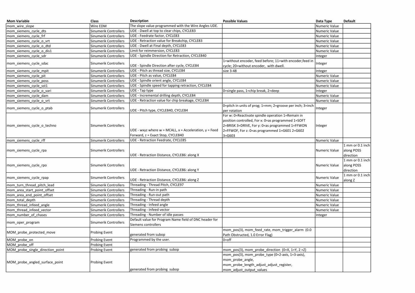
Mom Variable Class Description Possible Values Data Type Default
mom_wire_slope Wire EDM The slope value programmed with the Wire Angles UDE. Numeric Value
mom_siemens_cycle_dts Sinumerik Controllers UDE - Dwell at top to clear chips, CYCLE83 Numeric Value
mom_siemens_cycle_frf Sinumerik Controllers UDE - Feedrate factor, CYCLE83 Numeric Value
mom_siemens_cycle_o_vrt Sinumerik Controllers UDE - Retraction value for Breakchip, CYCLE83 Numeric Value
mom_siemens_cycle_o_dtd Sinumerik Controllers UDE - Dwell at Final depth, CYCLE83 Numeric Value
mom_siemens_cycle_o_dis1 Sinumerik Controllers Limit for reimmersion, CYCLE83 Numeric Value
mom_siemens_cycle_sdr Sinumerik Controllers UDE - Spindle Direction for Retraction, CYCLE840 Integer
mom_siemens_cycle_sdac Sinumerik ControllersUDE - Spindle Direction after cycle, CYCLE84
1=without encoder, feed before; 11=with encoder,feed in
cycle; 20=without encoder, with dwell.Integer
mom_siemens_cycle_mpit Sinumerik Controllers UDE - Pitch as thread size, CYCLE84 size 3-48 Integer
mom_siemens_cycle_pit Sinumerik Controllers UDE - Pitch as value, CYCLE84 Numeric Value
mom_siemens_cycle_poss Sinumerik Controllers UDE - Spindle orient angle, CYCLE84 Numeric Value
mom_siemens_cycle_sst1 Sinumerik Controllers UDE - Spindle speed for tapping retraction, CYCLE84 Numeric Value
mom_siemens_cycle_o_vari Sinumerik Controllers UDE - Tap type 0=single pass, 1=chip break, 2=deep Integer
mom_siemens_cycle_dam Sinumerik Controllers UDE - Incremental drilling depth, CYCLE84 Numeric Value
mom_siemens_cycle_o_vrt Sinumerik Controllers UDE - Retraction value for chip breakage, CYCLE84 Numeric Value
mom_siemens_cycle_o_ptab Sinumerik ControllersUDE - Pitch type, CYCLE840, CYCLE84
0=pitch in units of prog; 1=mm; 2=groove per inch; 3=inch
per rotationInteger
mom_siemens_cycle_o_techno Sinumerik ControllersUDE - wxyz where w = MCALL, x = Acceleration, y = Feed
Forward, z = Exact Stop, CYCLE840
For w: 0=Reactivate spindle operation 1=Remain in
position controlled, For x: 0=as programmed 1=SOFT
2=BRISK 3=DRIVE, For y: 0=as programmed 1=FFWON
2=FFWOF, For z: 0=as programmed 1=G601 2=G602
3=G603
Integer
mom_siemens_cycle_rff Sinumerik Controllers UDE - Retraction Feedrate, CYCLE85 Numeric Value
mom_siemens_cycle_rpa Sinumerik ControllersUDE - Retraction Distance, CYCLE86: along X
Numeric Value
1 mm or 0.1 inch
along POSS
direction
mom_siemens_cycle_rpo Sinumerik ControllersUDE - Retraction Distance, CYCLE86: along Y
Numeric Value
1 mm or 0.1 inch
along POSS
direction
mom_siemens_cycle_rpap Sinumerik ControllersUDE - Retraction Distance, CYCLE86: along Z
Numeric Value1 mm or 0.1 inch
along Z
mom_turn_thread_pitch_lead Sinumerik Controllers Threading - Thread Pitch, CYCLE97 Numeric Value
mom_area_start_point_offset Sinumerik Controllers Threading - Run-in path Numeric Value
mom_area_end_point_offset Sinumerik Controllers Threading - Run-out path Numeric Value
mom_total_depth Sinumerik Controllers Threading - Thread depth Numeric Value
mom_thread_infeed_angle Sinumerik Controllers Threading - Infeed angle Numeric Value
mom_thread_infeed_vector Sinumerik Controllers Threading - Infeed vector Numeric Value
mom_number_of_chases Sinumerik Controllers Threading - Number of idle passes Integer
mom_oper_program Sinumerik ControllersDefault value for Program Name field of DNC header for
Siemens controllers
MOM_probe_protected_move Probing Eventgenerated from subop
mom_pos(3), mom_feed_rate, mom_trigger_alarm (0.0
Path Obstructed, 1.0 Error Flag)
MOM_probe_on Probing Event Programmed by the user. 0=off
MOM_probe_off Probing Event
MOM_probe_single_direction_point Probing Event generated from probing subop mom_pos(3), mom_probe_direction (0=X, 1=Y, 2 =Z)
MOM_probe_angled_surface_point Probing Event
generated from probing subop
mom_pos(3), mom_probe_type (0=2-axis, 1=3-axis),
mom_probe_angle,
mom_probe_length_adjust_adjust_register,
mom_adjust_output_values
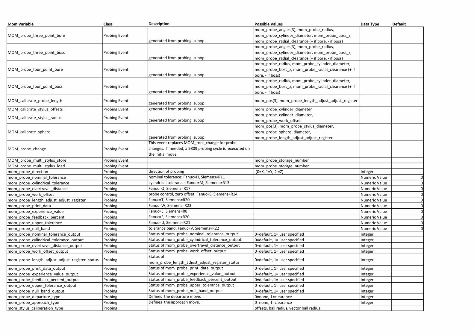
Mom Variable Class Description Possible Values Data Type Default
MOM_probe_three_point_bore Probing Eventgenerated from probing subop
mom_probe_angles(3), mom_probe_radius,
mom_probe_cylinder_diameter, mom_probe_boss_z,
mom_probe_radial_clearance (+ if bore, - if boss)
MOM_probe_three_point_boss Probing Eventgenerated from probing subop
mom_probe_angles(3), mom_probe_radius,
mom_probe_cylinder_diameter, mom_probe_boss_z,
mom_probe_radial_clearance (+ if bore, - if boss)
MOM_probe_four_point_bore Probing Eventgenerated from probing subop
mom_probe_radius, mom_probe_cylinder_diameter,
mom_probe_boss_z, mom_probe_radial_clearance (+ if
bore, - if boss)
MOM_probe_four_point_boss Probing Eventgenerated from probing subop
mom_probe_radius, mom_probe_cylinder_diameter,
mom_probe_boss_z, mom_probe_radial_clearance (+ if
bore, - if boss)
MOM_calibrate_probe_length Probing Eventgenerated from probing subop
mom_pos(3), mom_probe_length_adjust_adjust_register
MOM_calibrate_stylus_offsets Probing Event generated from probing subop mom_probe_cylinder_diameter
MOM_calibrate_stylus_radius Probing Eventgenerated from probing subop
mom_probe_cylinder_diameter,
mom_probe_work_offset
MOM_calibrate_sphere Probing Eventgenerated from probing subop
mom_pos(3), mom_probe_stylus_diameter,
mom_probe_sphere_diameter,
mom_probe_length_adjust_adjust_register
MOM_probe_change Probing Event
This event replaces MOM_tool_change for probe
changes. If needed, a 9809 probing cycle is executed on
the initial move.
MOM_probe_multi_stylus_store Probing Event mom_probe_storage_number
MOM_probe_multi_stylus_load Probing Event mom_probe_storage_number
mom_probe_direction Probing direction of probing (0=X, 1=Y, 2 =Z) Integer
mom_probe_nominal_tolerance Probing nominal tolerance: Fanuc=H, Siemens=R11 Numeric Value 0
mom_probe_cylindrical_tolerance Probing cylindrical tolerance: Fanuc=M, Siemens=R13 Numeric Value 0
mom_probe_overtravel_distance Probing Fanuc=Q, Siemens=R17 Numeric Value 0
mom_probe_work_offset Probing probe control, zero offset: Fanuc=S, Siemens=R14 Numeric Value 0
mom_probe_length_adjust_adjust_register Probing Fanuc=T, Siemens=R20 Numeric Value 0
mom_probe_print_data Probing Fanuc=W, Siemens=R23 Numeric Value 0
mom_probe_experience_value Probing Fanuc=E, Siemens=R8 Numeric Value 0
mom_probe_feedback_percent Probing Fanuc=F, Siemens=R20 Numeric Value 0
mom_probe_upper_tolerance Probing Fanuc=U, Siemens=R21 Numeric Value 0
mom_probe_null_band Probing tolerance band: Fanuc=V, Siemens=R22 Numeric Value 0
mom_probe_nominal_tolerance_output Probing Status of mom_probe_nominal_tolerance_output 0=default, 1= user specified Integer
mom_probe_cylindrical_tolerance_output Probing Status of mom_probe_cylindrical_tolerance_output 0=default, 1= user specified Integer
mom_probe_overtravel_distance_output Probing Status of mom_probe_overtravel_distance_output 0=default, 1= user specified Integer
mom_probe_work_offset_output Probing Status of mom_probe_work_offset_output 0=default, 1= user specified Integer
mom_probe_length_adjust_adjust_register_status ProbingStatus of
mom_probe_length_adjust_adjust_register_status0=default, 1= user specified Integer
mom_probe_print_data_output Probing Status of mom_probe_print_data_output 0=default, 1= user specified Integer
mom_probe_experience_value_output Probing Status of mom_probe_experience_value_output 0=default, 1= user specified Integer
mom_probe_feedback_percent_output Probing Status of mom_probe_feedback_percent_output 0=default, 1= user specified Integer
mom_probe_upper_tolerance_output Probing Status of mom_probe_upper_tolerance_output 0=default, 1= user specified Integer
mom_probe_null_band_output Probing Status of mom_probe_null_band_output 0=default, 1= user specified Integer
mom_probe_departure_type Probing Defines the departure move. 0=none, 1=clearance Integer
mom_probe_approach_type Probing Defines the approach move. 0=none, 1=clearance Integer
mom_stylus_caliberation_type Probing offsets, ball radius, vector ball radius
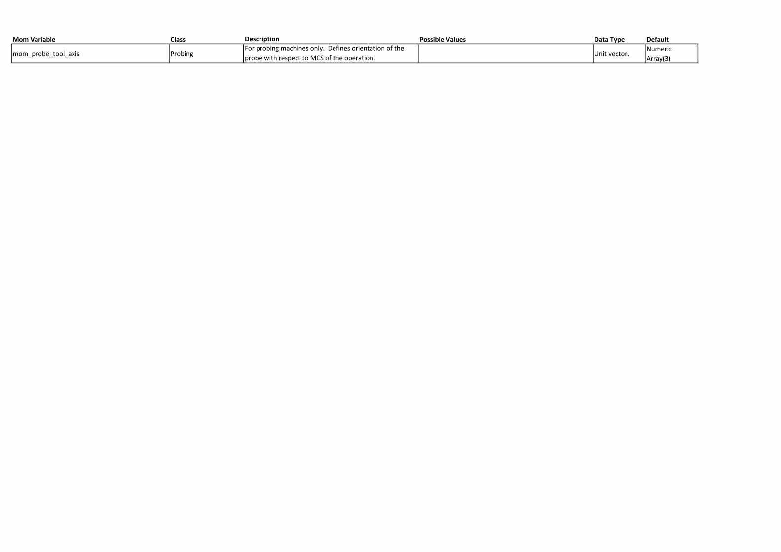
Mom Variable Class Description Possible Values Data Type Default
mom_probe_tool_axis ProbingFor probing machines only. Defines orientation of the
probe with respect to MCS of the operation. Unit vector.
Numeric
Array(3)