Embed Size (px)
Citation preview
Air Quality Standard Permit For
Oil and Gas Handling and Production Facilities Note for all Readers: Acronym List at End of Document I. Executive Summary
The Texas Commission on Environmental Quality (TCEQ or commission) is issuing amendments to the Air Quality Standard Permit for Oil and Gas Handling and Production Facilities.
II. Explanation and Background of Air Quality Standard Permit
On January 26, 2011, the TCEQ issued a non-rule standard permit for oil and gas production facilities. The standard permit became effective on April 1, 2011 and applied only in the following counties making up the Barnett Shale region of the state: Archer, Bosque, Clay, Comanche, Cooke, Coryell, Dallas, Denton, Eastland, Ellis, Erath, Hill, Hood, Jack, Johnson, Montague, Palo Pinto, Parker, Shackelford, Stephens, Somervell, Tarrant, and Wise. The commission is issueing a corrected standard permit to address typographical errors, formatting, and duplicative language.
III. Overview of Air Quality Standard Permit
The standard permit includes operating specifications and emissions limitations for typical equipment and facilities used during normal operation, which includes production and planned maintenance, startup, and shutdown (MSS). The standard permit references the new federal standards which have been promulgated by the United States Environmental Protection Agency (EPA), and includes criteria for registration and changes at existing, authorized sites. It also specifically addresses the appropriateness of multiple authorizations at one contiguous property.
IV. Permit Condition Analysis and Justification
The commission is amending subsection (m), table 8 to remove unnecessary, repetitive language under the heading Control Devices, Control with process combustion or heating devices (e.g. reboilers, heatersand furnaces). Additionally, there have been nonsubstantive corrections to typographical errors and formatting changes.
V. Protectiveness Review
None of the conditions affecting protectiveness are being changed in this amendment, therefore a protectiveness review was not produced.
This form is for use by facilities subject to air quality permit requirements and may be revised periodically.Oil and Gas Standard Permit (Revised 02/12) Page 1 of 81

VI. Public Notice and Comment Period
In accordance with 30 TAC §116.603, Public Participation in Issuance of Standard Permits, the TCEQ published notice of the proposed standard permit in the Texas Register and newspapers of the largest general circulation in the following metropolitan areas: Austin, Dallas, and Houston. The date for the newspaper publications was August 22, 2011. The date of the Texas Register notice was September 2, 2011. The public comment period ran from the date of newspaper publication until 5:00 p.m. on October 3, 2011. Written comments were received from the Texas Oil and Gas Association (TxOGA).
VII. Public Meeting
A public meeting was held on the proposed amendments to the Air Quality Standard Permit for Oil and Gas Handling and Production Facilities on October 3, 2011, and no comments were submitted.
VIII. Analysis of Comments
TxOGA expressed appreciation for the removal of unnecessary, repetitive language in section (m) of the standard permit provided that the change is not substantive. The commission thanks TxOGA for its support of this amendment to the standard permit and confirms that the change is a non-substantive removal of a typographical error. TxOGA also stated that it would object to any changes resulting from other comments made in reference this amendment to the standard permit. Additionally TxOGA stated that Senate Bill (SB) 1134 from the 82nd Regular Legislative Session precluded any changes to §106.352 unless accompanied by the requisite regulatory impact analysis and air monitoring data. No other comments were received on this amendment, consequently, there will be no additional changes resulting from comments. Also, the commission will not make changes that would conflict with the requirements of SB 1134. However, the commission may make non-substantive corrections to typographical errors or formatting changes necessary for this standard permit amendment.
This form is for use by facilities subject to air quality permit requirements and may be revised periodically.Oil and Gas Standard Permit (Revised 02/12) Page 2 of 81
IX. Statutory Authority
The amendments to this standard permit are proposed under the Texas Clean Air Act (TCAA), Texas Health and Safety Code (THSC), §382.011, General Powers and Duties, which authorizes the commission to control the quality of the state's air, THSC §382.051, Permitting Authority of Commission; Rules, which authorizes the commission to issue permits, including standard permits for similar facilities, and THSC §382.0513, Permit Conditions, which authorizes the commission to establish and enforce permit conditions consistent with the TCAA, THSC §382.05195, Standard Permit, which authorizes the commission to issue standard permits according to the procedures set out in that standard permit, and THSC §382.051963 which authorizes the commission to make certain amendments to the standard permit.
This form is for use by facilities subject to air quality permit requirements and may be revised periodically.Oil and Gas Standard Permit (Revised 02/12) Page 3 of 81

Air Quality Standard Permit For
Oil and Gas Handling and Production Facilities EffectiveJanuary 11, 2012
(a) Applicability. This standard permit applies to all stationary facilities, or groups of
facilities, at a site which handle gases and liquids associated with the production, conditioning, processing, and pipeline transfer of fluids or gases found in geologic formations on or beneath the earth’s surface including, but not limited to, crude oil, natural gas, condensate, and produced water with the following conditions.
(1) The requirements in paragraphs (a)-(k) of this standard permit are applicable in only
for new projects and dependent facilities located in the Barnett Shale (Archer, Bosque, Clay, Comanche, Cooke, Coryell, Dallas, Denton, Eastland, Ellis, Erath, Hill, Hood, Jack, Johnson, Montague, Palo Pinto, Parker, Shackelford, Stephens, Somervell, Tarrant, and Wise Counties) on or after April 1, 2011. For all other new projects and dependent facilities in all other counties of the state, paragraph (l) of this standard permit is applicable.
(2) Only one Air Quality Standard Permit for Oil and Gas Handling and Production
Facilities for an oil and gas site (OGS) may be registered for a combination of dependent facilities and authorizes all facilities in sweet or sour service. This standard permit may not be used if operationally dependent facilities are authorized by the permit by rule in Title 30, Texas Administrative Code (30 TAC) §106.352, Oil and Gas Handling and Production Facilities, or a permit under 30 TAC §116.111,General Application. Existing authorized facilities, or groups of facilities, at an OGS under this standard permit which are not changing certified character or quantity of emissions must only meet subsections (i) and (k) of this standard permit (protectiveness review and planned maintenance, startup, and shutdown (MSS) requirements) and otherwise retain their existing authorization. Other facilities which are not covered under this standard permit may be authorized by other authorizations at an OGS if (b)(6) and (k) of this standard permit are met.
(3) This standard permit does not relieve the owner or operator from complying with
any other applicable provision of the Texas Health and Safety Code, Texas Water Code, rules of the Texas Commission on Environmental Quality (TCEQ), or any additional local, state or federal regulations. Emissions that exceed the limits in this standard permit are not authorized and are violations.
(4) Emissions from upsets, emergencies, or malfunctions are not authorized by this
standard permit. This standard permit does not regulate methane, ethane, or carbon dioxide.
This form is for use by facilities subject to air quality permit requirements and may be revised periodically.Oil and Gas Standard Permit (Revised 02/12) Page 4 of 81
(b) Definitions and Scope.
(1) Facility is a discrete or identifiable structure, device, item, equipment, or enclosure that constitutes or contains a stationary source. Stationary sources associated with a mine, quarry, or well test lasting less than 72 hours are not considered facilities.
(2) Receptor includes any building which is in use as a single or multi-family residence,
school, day-care, hospital, business, or place of worship at the time this standard permit is registered. A residence is a structure primarily used as a permanent dwelling. A business is a structure that is occupied for at least 8 hours a day, 5 days a week, and does not include businesses who are handling or processing materials as described in subsection (a). This term does not include structures occupied or used solely by the owner or operator of the oil and gas facility, or the mineral rights owner of the property upon which the facility is located. All measurements of distance to receptors shall be taken from the emission release point at the oil and gas facility that is nearest to the point on the building that is nearest to the oil and gas facility.
(3) An OGS is defined as all facilities which meet the following:
(A) Located on contiguous or adjacent properties; (B) Under common control of the same person (or persons under common
control); and (C) Designated under same 2-digit standard industrial classification (SIC) codes.
(4) For purposes of determining applicability of 30 TAC Chapter 122, Federal
Operating Permits, the definitions of 30 TAC §122.10, General Definitions, apply.
(5) A project under this standard permit is defined as the following and must meet all requirements of this standard permit prior to construction or implementation of changes. (A) Any new facility or new group of operationally dependent facilities at an
OGS; or (B) Physical changes to existing authorized facilities or group of facilities at an
OGS which increase the potential to emit over previously registered emission limits; or
(C) Operational changes to existing authorized facilities or group of facilities at an OGS which increase the potential to emit over previously registered emission limits.
This form is for use by facilities subject to air quality permit requirements and may be revised periodically.Oil and Gas Standard Permit (Revised 02/12) Page 5 of 81

(6) For purposes of registration under this standard permit, the following facilities shall
be included: (A) All facilities or groups of facilities at an OGS which are operationally
dependent on each other; (B) Facilities must be located within a 1/4 mile of a project emission point, vent,
or fugitive component, except for those components excluded in (b)(6)(C) of this standard permit;
(C) If piping or fugitive components are the only connection between facilities and the distance between facilities exceeds 1/4 mile, then the facilities are considered separate for purposes of this registration;
(D) The boundaries of the registration become fixed at the time this standard permit is registered. No individual facility may be authorized under more than one registration;
(E) Any facility or group of facilities authorized under an existing standard permit registration which is operationally dependent on a project must be revised to incorporate the project; and
(F) A registration may include facilities which are claiming 30 TAC §116.620, Installation and/or Modification of Oil and Gas Facilities as well as projects which are claiming this standard permit. Existing authorized facilities, or group of facilities, at an OGS under this standard permit which are not changing registered and certified character or quantity of emissions must only meet paragraphs (i) and (k) of this standard permit (the protectiveness review and planned maintenance, startup, and shutdown (MSS) requirements) until the registration is renewed after December 31, 2015, after which paragraphs (a) – (k) of this standard permit apply.
(7) For purposes of all previous claims of this standard permit (or any previous version
of this standard permit) where no project is occurring: (A) Existing authorized facilities, or group of facilities, which have not registered
planned MSS activity emissions prior to the effective dates in (a)(1) of this standard permit must meet paragraph (i) of this standard permit (planned MSS) no later than January 5, 2012; or
(B) Existing authorized facilities, or group of facilities, which have registered planned MSS activity emissions and compliance with 30 TAC §116.620(a)(1) has been demonstrated prior to the effective dates in (a)(1) of this standard permit, must meet paragraph (i) of this standard permit (planned MSS) no later than the registration renewal submitted after December 31, 2015.
(8) For purposes of ensuring protection of public health and welfare and demonstrating
compliance with applicable ambient air standards and effects screening levels, the impacts analysis as specified in paragraph (k) of this standard permit must be completed. (A) All impacts analysis must be done on a contaminant-by-contaminant basis for
any net project increases. If a claim under this standard permit is only for planned MSS under paragraph (i) of this standard permit, the analysis shall evaluate planned MSS scenarios only.
This form is for use by facilities subject to air quality permit requirements and may be revised periodically.Oil and Gas Standard Permit (Revised 02/12) Page 6 of 81
(B) Hourly and annual emissions shall be limited based on the most stringent
of paragraphs (h) or (k) of this standard permit.
(c) Authorized Facilities, Changes and Activities.
(1) For existing OGS which are authorized by previous versions of this standard permit: (A) A project requires registration unless otherwise specified. (B) The following projects do not require registration, but must comply with best
management practices in paragraph (e) of this standard permit, compliance demonstrations in paragraphs (i) and (j) of this standard permit and must be incorporated into the registration at the next revision or certification: (i) Addition of any piping, fugitive components, any other new facilities
that increase registered emissions less than or equal to 1.0 tpy volatile organic compounds (VOC), 5.0 tpy nitrogen oxides (NOx), 0.01 tpy benzene, and 0.05 tpy hydrogen sulfide (H2S) over a rolling 12-month period;
(ii) Changes to any existing facilities that increase registered emissions less than or equal to 1.0 tpy VOC, 5.0 tpy nitrogen oxides (NOx), 0.01 tpy benzene, and 0.05 tpy H2S over a rolling 12-month period; or
(iii) Total increases over a rolling 60-month period that are less than or equal to 5.0 tpy VOC or NOX, 0.05 tpy benzene, or 0.1 tpy H2S; or
(iv) Addition of any new engine rated less than 100 horsepower (hp); or (v) Replacement of any facility if the new facility does not increase the
previous registered emissions. (C) In lieu of registering proposed changes under this standard permit, incremental
emissions increases associated with construction of new facilities or changes to existing facilities may be authorized by 30 TAC §106.261, Facilities (Emission Limitations) or §106.262, Facilities (Emissions and Distance Limitations), if the maximum worst-case emissions also meet the limitations established by paragraphs (b)(8) and (k) of this standard permit for all air contaminants with proposed increases.
(2) All authorizations under this standard permit shall meet the following:
(A) New, changed, or replacement facilities shall not exceed the thresholds for major source or major modification as defined in 30 TAC §116.12, Nonattainment and Prevention of Significant Deterioration Review Definitions, and in Federal Clean Air Act §112(g) or §112(j);
(B) All facilities shall comply with all applicable 40 Code of Federal Regulations (CFR), Parts 60, 61, and 63 requirements for New Source Performance Standards (NSPS), National Emission Standards for Hazardous Air Pollutants (NESHAP), and Maximum Achievable Control Technology (MACT); and
This form is for use by facilities subject to air quality permit requirements and may be revised periodically.Oil and Gas Standard Permit (Revised 02/12) Page 7 of 81
(C) All facilities shall comply with all applicable requirements of 30 TAC
Chapters 111, Control of Air Pollution from Visible Emissions and Particulate Matter, 112, Control of Air Pollution from Sulfur Compounds, 113, Standards of Performance for Hazardous Air Pollutants and for Designated Facilities and Pollutants, 115, Control of Air Pollution from Volatile Organic Compounds), and 117, Control of Air Pollution from Nitrogen Compounds.
(3) To be eligible for this standard permit an applicant:
(A) shall meet all applicable requirements as set forth in this standard permit; (B) shall not misrepresent or fail to fully disclose all relevant facts in obtaining the
permit; and (C) shall not be indebted to the state for failure to make payment of penalties or
taxes imposed by the statutes or rules within the commission’s jurisdiction.
(4) All facilities related to the operation of any OGS, under any version of this standard permit (or co-located at a site with an OGS standard permit), previously authorized by, and continuing to meet, the conditions of a permit by rule under 30 TAC Chapter 106, Permits by Rule (or any historical version) must: (A) Be incorporated into this standard permit in any initial registration, revision,
or renewal for this standard permit. These facilities will become authorized by this standard permit and previous authorizations will be voided.
(B) Meet all emission limits established by this standard permit and review in accordance with paragraph (b)(8) of this standard permit.
(C) Meet requirements of paragraphs (e), (i), and (j) of this standard permit for Best Management Practices and Minimum Requirements, Planned MSS, and associated Records, Sampling and Monitoring of this standard permit.
(D) Only if facilities or groups of facilities are changed in such a way as to increase the potential to emit, production processing capacity, or registered emission rate, the requirements in paragraph (e) (h) (BACT) of this standard permit are required to be met. In all other cases, these facilities are not required to meet paragraph (e) (h) of this standard permit.
(d) Facilities and Exclusions
(1) Only the following specific facilities and groups of facilities have been evaluated for this standard permit, along with supporting infrastructure equipment and facilities, and may be included in a registration:
(A) Fugitive components, including valves, pressure relief valves, pipe flanges
and connectors, pumps, compressors, stuffing boxes, instrumentation and meters, natural gas driven pneumatic pumps, and other similar devices with seals that separate process and waste material from the atmosphere and the associated piping;
(B) Separators, including all gas, oil and water physical separation units;
This form is for use by facilities subject to air quality permit requirements and may be revised periodically.Oil and Gas Standard Permit (Revised 02/12) Page 8 of 81

(C) Treatment and processing equipment, including heater-treaters, methanol
injection, glycol dehydrators, molecular or mole sieves, amine sweeteners, H2S scavenger chemical reaction vessels for sulfur removal, and iron sponge units;
(D) Cooling towers and associated heat exchangers; (E) Gas recovery units, including cryogenic expansion, absorption, adsorption,
heat exchangers and refrigeration units; (F) Combustion units, including engines, turbines, boilers, reboilers, and heaters; (G) Storage tanks for crude oil, condensate, produced water fuels, treatment
chemicals, slop and sump oils and pressure tanks with liquified petroleum gases;
(H) Surface facilities associated with underground storage of gas or liquids; (I) Truck loading equipment; (J) Control equipment, including vapor recovery systems, glycol and amine
reboiler condensers, flares, vapor combustors, and thermal oxidizers; and (K) Temporary facilities used for planned maintenance, and temporary control
devices for planned start-ups and shutdowns.
(2) Exclusions. The following are not authorized under this standard permit: (A) Sour water strippers or sulfur recovery units; (B) Carbon dioxide hot carbonate processing units; (C) Water injection facilities (these facilities may otherwise authorized by
30 TAC §106.351, Salt Water Disposal); (D) Liquefied petroleum gases, crude oil, or condensate transfer or loading into or
from railcars, ships, or barges. These facilities may otherwise be authorized by 30 TAC §106.261, Facilities (Emission Limitations)) and §106.262, Facilities (Emissions and Distance Limitations);
(E) Incinerators for solid waste destruction; (F) Remediation of petroleum contaminated water and soil. These facilities may
otherwise authorized by 30 TAC §106.533, Remediation; and (G) Cooling Towers and heat exchangers with direct contact with gaseous or
liquid process streams containing VOC, H2S, halogens or halogen compounds, cyanide compounds, inorganic acids, or acid gases.
(e) Best Management Practices (BMP) and Best Available Control Technology (BACT)
Requirements. For any project, and any associated emission control equipment registered under this standard permit this paragraph shall be met as applicable. These requirements are not applicable to existing, unchanging facilities until any renewal submitted after December 31, 2015.
This form is for use by facilities subject to air quality permit requirements and may be revised periodically.Oil and Gas Standard Permit (Revised 02/12) Page 9 of 81

(1) All facilities which have the potential to emit air contaminants must be maintained in good working order and operated properly during facility operations. Each operator shall establish and maintain a program to replace, repair, and/or maintain facilities to keep them in good working order. The minimum requirements of this program shall include: (A) Compliance with manufacturer's specifications and recommended programs
applicable to equipment performance and effect on emissions, or alternatively, an owner or operator developed maintenance plan for such equipment that is consistent with good air pollution control practices.
(B) Cleaning and routine inspection of all equipment; and (C) Replacement and repair of equipment on schedules which prevent equipment
failures and maintain performance.
(2) Any OGS facility shall be operated at least 50 feet from any property line or receptor (whichever is closer to the facility). This distance limitation does not apply to the following: (A) Any fugitive components that are used for isolation and or safety purposes
may be located at one-half of the width of any applicable easement; (B) Any facility at a location for which the distance requirements were satisfied at
the time this standard permit is registered (provided that the authorization was maintained) regardless of whether a receptor is subsequently built or put to use 50 feet from any OGS facility; or
(C) Existing facilities which are located less than 50 feet from a property line or receptor when constructed and previously authorized. If modified or replaced, the operator shall consider, to the extent that good engineering practice will permit, moving these facilities to meet the 50 foot requirement. Replacement facilities must meet all other requirements of this standard permit.
(3) Engines and turbines shall meet the emission and performance standards listed in
Table 6 in paragraph (m) and the following requirements: (A) Liquid fueled engines used for back-up power generation and periodic power
needs at the OGS are authorized if the fuel has no more than 0.05% sulfur and the engine is operated less than 876 hours per rolling 12-month period.
(B) Engines and turbines used for electric generation more than 876 hours per rolling 12-month period are authorized if no reliable electric service is readily available. In all other circumstances, electric generators must meet the technical requirements of the Air Quality Standard Permit for Electric Generating Unit (EGU) (not including the EGU standard permit registration requirements) and the emissions shall be included in the registration under this standard permit;
(C) All applicable requirements of 30 TAC Chapter 117; and
This form is for use by facilities subject to air quality permit requirements and may be revised periodically.Oil and Gas Standard Permit (Revised 02/12) Page 10 of 81

(D) All applicable requirements of 40 CFR Part 60 and 40 CFR Part 63. (E) Compression ignition engines that are rated less than 225 kW (300 hp) and
emit less than or equal to the emission tier for an equivalent sized model year 2008 non-road compression ignition engine located at 40 CFR § 89.112, Table 1 are authorized.
(4) Open-topped tanks or ponds containing VOCs or H2S are allowed up to a PTE equal
to 1 tpy of VOC and 0.1 tpy of H2S. (5) All process equipment and storage facilities individually must meet the
requirements of BACT listed in Table 10 in paragraph (m). Any combination of process equipment and storage facilities with an uncontrolled PTE of equal to or greater than 25 tpy of VOC must also meet the requirements of Table 10, row titled “Combined Control Requirements”. All of the following streams and facilities must be included for this site-wide assessment: (A) For any gaseous vent stream with a concentration of 1% VOC must be
considered for capture and control requirements; (B) For any liquid stream with a potential to emit of equal to or greater than 1 tpy
VOC for each vessel or storage facility.
(6) The following shall apply to all fugitive components associated with the project: (A) All seals and gaskets in VOC or H2S service shall be installed, checked, and
properly maintained to prevent leaking. All components shall be physically inspected quarterly for leaks.
(B) New and replaced fugitive components and instrumentation in gas or liquid service with the uncontrolled potential to emit equal to or greater than 10 tpy VOC or 1 tpy H2S are subject to a leak detection and repair (LDAR) program as specified in Table 9 in paragraph (m). Additional requirements are applicable where uncontrolled potential to emit equal to or greater than 25 tpy VOC or 5 tpy H2S as specified in Table 9. Planned MSS from fugitive components must also meet the requirements of Table 9.
(C) All components found to be leaking shall be repaired. Every reasonable effort shall be made to repair a leaking component. All leaks not repaired immediately shall be tagged or noted in a log. At manned sites, leaks shall be repaired no later than 30 days after the leak is found. At unmanned sites, leaks shall be repaired no later than 60 days after the leak is found. If the repair of a component would require a unit shutdown, which would create more emissions than the repair would eliminate, the repair may be delayed until the next shutdown.
(D) Tank hatches, not designed to be completely sealed, shall remain closed (but not completely sealed in order to maintain safe design functionality) except for sampling, gauging, loading, unloading, or planned maintenance activities.
This form is for use by facilities subject to air quality permit requirements and may be revised periodically.Oil and Gas Standard Permit (Revised 02/12) Page 11 of 81
(E) To the extent that good engineering practices will permit, new and reworked
valves and piping connections shall be located in a place that is reasonably accessible for leak checking during plant operation and underground process pipelines shall contain no buried valves such that fugitive emission monitoring is rendered impractical.
(7) Tanks and vessels must utilize a paint color that minimizes the effects of solar
heating (including, but not limited to, white or aluminum). To meet this requirement the solar absorptance should be 0.43 or less, as referenced in Table 7.1-6 in Compilation of Air Pollutant Emission Factors (AP-42). Paint shall be applied according to paint producers recommended application requirements if provided and in sufficient quantity as to be considered solar resistant. Paint shall be maintained in good condition and will not compromise tank integrity. Minimal amounts of rust may be present not to exceed 10% of the external surface area of the roof or walls of the tank and in no way may compromise tank integrity. Additionally, up to 10% of the external surface area of the roof or walls of the tank or vessel may be painted with other colors to allow for identification and/or aesthetics. For tanks and vessels purposefully darkened to create the process reaction and help condense liquids from being entrained in the vapor or are in an area whereby a local, state, federal law, ordinance, or private contract predating this standard permit’s effective date establishes in writing tank and vessel colors other than white, these requirements do not apply.
(8) All emission estimation methods including but not limited to computer programs
such as GRI-GLYCalc, AmineCalc, E&P Tanks, and Tanks 4.0, must be used with monitoring data generated in accordance with Table 8 in subsection (m) of this section where monitoring is required. All emission estimation methods must also be used in a way that is consistent with protocols established by the commission or promulgated in federal regulations (NSPS, NESHAPS). Where control of emissions is relied upon to meet subsection (k) of this section, control monitoring is required.
(9) Process reboilers, heaters, and furnaces that are also used for control of waste gas
streams may claim 50 to 99% destruction efficiency for VOCs and H2S depending on the design and level of monitoring applied. The 90% destruction may be claimed where the waste gas is delivered to the flame zone or combustion fire box with basic monitoring as specified in paragraph (j). Any value greater than 90% and up to 99% destruction efficiency may be claimed where enhanced monitoring and/or testing are applied as specified in paragraph (j). If the waste gas is premixed with the primary fuel gas and used as the primary fuel in the device through the primary fuel burners, 99% destruction may be claimed with basic monitoring as specified in paragraph (j). In systems where the combustion device is designed to cycle on and off to maintain the designed heating parameters, and may not fully utilize the waste gas stream, records of run time and enhanced monitoring is required to claim any run time beyond 50%.
This form is for use by facilities subject to air quality permit requirements and may be revised periodically.Oil and Gas Standard Permit (Revised 02/12) Page 12 of 81
(10) Vapor recovery Systems (VRSs) may claim up to 100% control. The control
efficiency is based on whether it is a mechanical VRU (mVRU) or a liquid VRU (lVRU). The VRUs must meet the appropriate design, monitoring and record-keeping in Table 7 and Table 8 in paragraph (m).
(11) Flares used for control of emissions from production, planned MSS, emergency, or
upset events may claim design destruction efficiency of 98% for VOCs and H2S and 99% for VOCs containing no more than three carbon atoms that contain no elements other than carbon and hydrogen. All flares must be designed and operated in accordance with the following: (A) Meet specifications for minimum heating values of waste gas, maximum tip
velocity, and pilot flame monitoring found in 40 CFR §60.18; (B) If necessary to ensure adequate combustion, sufficient gas shall be added to
make the gases combustible; (C) An infrared monitor is considered equivalent to a thermocouple for flame
monitoring purposes; (D) An automatic ignition system may be used in lieu of a continuous pilot; (E) Flares must be lit at all times when gas streams are present; (F) Fuel for all flares shall be sweet gas or liquid petroleum gas except where only
field gas is available and it is not sweetened at the site; and (G) Flares shall be designed for and operated with no visible emissions, except for
periods not to exceed at total of 5 minutes during any 2 consecutive hours. Acid gas flares which must comply with opacity limits and records in accordance with 30 TAC §111.111(a)(4), Requirements for Specified Sources, regarding gas flares, are exempt from this visible emission limitation.
(I) Flares may be designed with steam or air assist to help reduce visible emissions from the flare but must meet the appropriate requirements in 40 CFR 60.18.
(J) At no time shall minimum heating values fall below the associated minimum heating value in 60.18
(12) Thermal oxidation and vapor combustion control devices may claim design
destruction efficiency from 90 to 99.9% for VOCs and H2S depending on the design and the level of monitoring and testing applied. A device designed for the variability of the waste gas streams it controls with basic monitoring to indicate oxidation or combustion is occurring when waste gas is directed to the device may claim 90% destruction efficiency. Devices with intermediate monitoring, designed for the variability of the waste gas streams they control, with a fire box or fire tube designed to maintain a temperature above 1,400 degrees Fahrenheit (F) for 0.5 seconds, residence time; or designed to meet the parameters of a flare with minimum heating values of waste gas, maximum tip velocity, and pilot flame monitoring as found in 40 CFR §60.18, but within a full or partial enclosure may claim a design destruction efficiency of 90 to 98%.
This form is for use by facilities subject to air quality permit requirements and may be revised periodically.Oil and Gas Standard Permit (Revised 02/12) Page 13 of 81
Devices with enhanced monitoring and ports and platforms to allow stack testing may claim a 99% efficiency where the devices are designed for the variability of the waste gas streams they control, with a fire box or fire tube designed to maintain a temperature above 1,400 degrees F for 0.5 seconds, residence time. The devices that can claim 99% destruction efficiency may claim 99.9% destruction efficiency if stack testing is conducted and confirms the efficiency and the enhanced monitoring is adjusted to ensure the continued efficiency. Temperature and residence time requirements may be modified if stack testing is conducted to confirm efficiencies.
(f) Registration, Revision, and Renewal Requirements
(1) For all previous claims of this standard permit (or any previous version of this standard permit) existing authorized facilities, or group of facilities, are not required to meet the requirements of this standard permit, with the exception of planned MSS, until a renewal under the standard permit is submitted after December 31, 2015.
(2) If no other changes except for authorizing planned MSS occurs at an existing OGS
under this standard permit, or any previous version of this standard permit, (b)(7) applies. (A) Records demonstrating compliance with paragraph (i) must be kept; (B) If the OGS must certify emissions to establish nonapplicability of prevention
of significant deterioration (PSD), nonattainment new source review (NNSR), or the federal operating permit programs, this certification may be filed using Form APD-CERT. No fee is required for this certification.
(C) Planned MSS shall be incorporated at the next revision or update to a registration under this standard permit after January 5, 2012, and no later than any renewal submitted after December 31, 2015.
(3) Facilities, groups of facilities or planned MSS from facilities registered under this
standard permit cannot also be authorized by a permit under 30 TAC §116.111, General Application.
(4) Prior to construction or implementation of changes for any project which meets this
standard permit a notification shall be submitted through the e-Permits system. This notification shall include the following: (A) Identifying information (Core Data) and a general description of the project
must be submitted through e-Permits (or if not available, hard-copy) using the "APD OGS New Project Notification."
(B) A fee of $25 for small businesses as defined in 30 TAC §106.50, or $50 for all others must be submitted through the commission's e-Pay system.
This form is for use by facilities subject to air quality permit requirements and may be revised periodically.Oil and Gas Standard Permit (Revised 02/12) Page 14 of 81
(5) For any registration which meets the emission limitations of this standard permit
must meet the following:
(A) Within 90 days after start of operation or implemented changes (whichever occurs first), the facilities must be registered with a PI-1S Standard Permit Application.
(B) This registration shall include a detailed summary of maximum emissions estimates based on: site-specific or defined representative gas and liquid analysis; equipment design specifications and operations; material type and throughput; and other actual parameters essential for accuracy for determining emissions and compliance with all applicable requirements of this standard permit.
(C) The fee for this registration shall be $475 for small businesses, or $850 for all others.
(D) Construction may begin any time after receipt of written notification to the executive director. Operations may continue after receipt of registration if there are no objections or 45 days after receipt by the executive director of the registration, whichever occurs first.
(6) If an OGS emissions increase, either through a change in production or addition of
facilities, the site may change authorization (Level 1 or Level 2 PBR in 30 TAC §106.352 or Standard Permit) in the following circumstances: (A) Within 90 days from the initial notification of construction of an oil and gas
facility, a registration can update the authorization mechanism by submitting an initial registration or revision to the PBR or Standard Permit.
(B) Within 90 days of the change of production or installation of additional equipment, by submitting an initial registration or revision to the PBR or Standard Permit.
(7) All registrations, registration revisions, and renewals shall be submitted to the
commission through a PI-1S Standard Permit Registration Form. Fee requirements do not apply when there are changes in representations with no increase in emissions within 6-months after a standard permit registration has been issued.
(g) Any claim under this standard permit must comply with all applicable requirements of
30 TAC §116.610; §116.611, Registration to Use a Standard Permit; §116.614, Standard Permit Fees; and §116.615, General Conditions. This standard permit supersedes: the notification requirements of 30 TAC §116.615, General Conditions; and the emission limitations of 30 TAC §116.610(a)(1), Applicability.
This form is for use by facilities subject to air quality permit requirements and may be revised periodically.Oil and Gas Standard Permit (Revised 02/12) Page 15 of 81
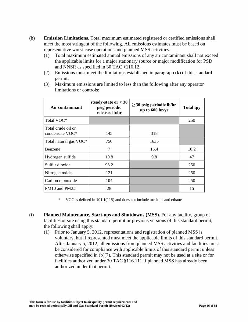
(h) Emission Limitations. Total maximum estimated registered or certified emissions shall
meet the most stringent of the following. All emissions estimates must be based on representative worst-case operations and planned MSS activities. (1) Total maximum estimated annual emissions of any air contaminant shall not exceed
the applicable limits for a major stationary source or major modification for PSD and NNSR as specified in 30 TAC §116.12.
(2) Emissions must meet the limitations established in paragraph (k) of this standard permit.
(3) Maximum emissions are limited to less than the following after any operator limitations or controls:
Air contaminant steady-state or < 30
psig periodic releases lb/hr
≥
30 psig periodic lb/hr up to 600 hr/yr
Total tpy
Total VOC*
250
Total crude oil or condensate VOC* 145 318
Total natural gas VOC* 750 1635
Benzene 7 15.4 10.2
Hydrogen sulfide 10.8 9.8 47
Sulfur dioxide 93.2 250
Nitrogen oxides 121 250
Carbon monoxide 104 250
PM10 and PM2.5 28 15
* VOC is defined in 101.1(115) and does not include methane and ethane
(i) Planned Maintenance, Start-ups and Shutdowns (MSS). For any facility, group of facilities or site using this standard permit or previous versions of this standard permit, the following shall apply: (1) Prior to January 5, 2012, representations and registration of planned MSS is
voluntary, but if represented must meet the applicable limits of this standard permit. After January 5, 2012, all emissions from planned MSS activities and facilities must be considered for compliance with applicable limits of this standard permit unless otherwise specified in (b)(7). This standard permit may not be used at a site or for facilities authorized under 30 TAC §116.111 if planned MSS has already been authorized under that permit.
This form is for use by facilities subject to air quality permit requirements and may be revised periodically.Oil and Gas Standard Permit (Revised 02/12) Page 16 of 81
(2) As specified, releases of air contaminants during, or as result of, planned MSS must
be quantified and meet the emission limits in this standard permit, as applicable. This analysis must include: (A) Alternate operational scenarios or redirection of vent streams; (B) Pigging, purging, and blowdowns; (C) Temporary facilities if used for degassing or purging of tanks, vessels, or other
facilities; (D) Degassing or purging of tanks, vessels, or other facilities; and (E) Management of sludge from pits, ponds, sumps, and water conveyances.
(3) Other planned MSS activities authorized by this standard permit are limited to the
following. These planned MSS activities require only recordkeeping of the activity. (A) Routine engine component maintenance including filter changes, oxygen
sensor replacements, compression checks, overhauls, lubricant changes, spark plug changes, and emission control system maintenance.
(B) Boiler refractory replacements and cleanings. (C) Heater and heat exchanger cleanings. (D) Turbine hot standard permit swaps. (E) Pressure relief valve testing, calibration of analytical equipment;
Instrumentation/analyzer maintenance; replacement of analyzer filters and screens.
(4) Engine/compressor start-ups associated with preventative system shutdown
activities have the option to be authorized as part of typical operations if: (A) Prior to operation, alternative operating scenarios to divert gas or liquid
streams are registered and certified with all supporting documentation; (B) Engine/compressor shutdowns shall result in no greater than 4 lbs/hr of
natural gas emissions; and (C) Emissions which result from subsequent compressor start-up activities are
controlled to a minimum of 98% efficiency for VOC and H2S. (j) Records, Sampling and Monitoring. The following records shall be maintained at a site
in written or electronic form and be readily available to the agency or local air pollution control program with jurisdiction upon request. All required records must be kept at the facility site. If the facility normally operates unattended, records must be maintained at an office within Texas having day-to-day operational control of the plant site. Other requirements, including but not limited to, federal recordkeeping or testing requirements, can be used to demonstrate compliance if the other requirements are at least as stringent as the associated requirements in the table below. Any documentation that is already being kept for other purposes will suffice for demonstrating requirements. If a control or method is not relied upon to meet this standard permit, then the associated sampling, monitoring, and records are not applicable. (1) Sampling and demonstrations of compliance shall include the requirements listed in
Table 7 in paragraph (m) of this standard permit.
This form is for use by facilities subject to air quality permit requirements and may be revised periodically.Oil and Gas Standard Permit (Revised 02/12) Page 17 of 81
(2) Monitoring and records for demonstrations of compliance shall include the
requirements listed in Table 8 in paragraph (m) of this standard permit. (k) Emission Limits Based on Impacts Evaluation.
(1) All impacts evaluations must be completed on a contaminant-by-contaminant basis
for only any net emissions increases resulting from a project and must meet the following as appropriate: (A) Compliance with state or federal ambient air standards shall be demonstrated
for NO2, SO2, and H2S at any property-line within 1 mile of a project. (B) Compliance with hourly effects screening levels (ESLs) for benzene and
annual ESL for benzene, shall be demonstrated at the nearest receptor within 1 mile of a project.
(2) Distance measurements shall be determined using the following:
(A) For each facility or group of facilities, the shortest corresponding distance from any emission point, vent, or fugitive component to the nearest receptor must be used with the appropriate compliance determination method with the published ESLs as found through the commissioner's internet webpage.
(B) For each facility or group of facilities, the shortest corresponding distance from any emission point, vent, or fugitive component to the nearest property line must be used with the appropriate compliance determination method with any applicable state or federal ambient air quality standard.
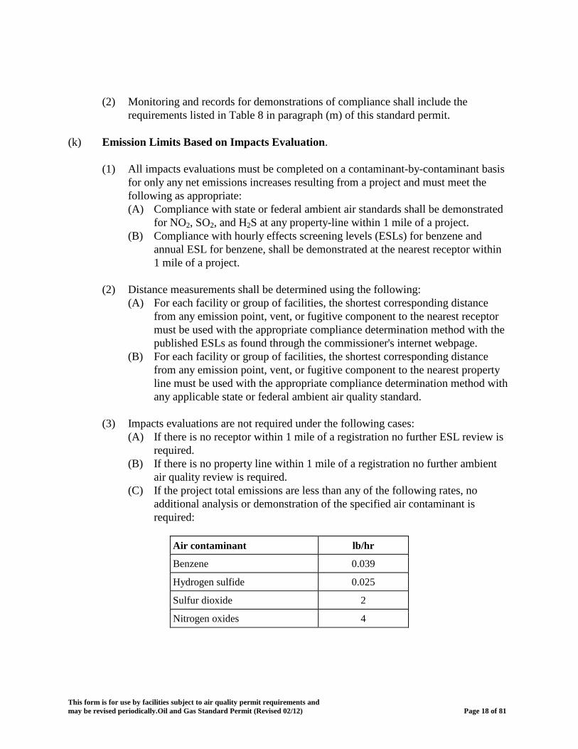
(3) Impacts evaluations are not required under the following cases:
(A) If there is no receptor within 1 mile of a registration no further ESL review is required.
(B) If there is no property line within 1 mile of a registration no further ambient air quality review is required.
(C) If the project total emissions are less than any of the following rates, no additional analysis or demonstration of the specified air contaminant is required:
Air contaminant lb/hr
Benzene 0.039
Hydrogen sulfide 0.025
Sulfur dioxide 2
Nitrogen oxides 4
This form is for use by facilities subject to air quality permit requirements and may be revised periodically.Oil and Gas Standard Permit (Revised 02/12) Page 18 of 81
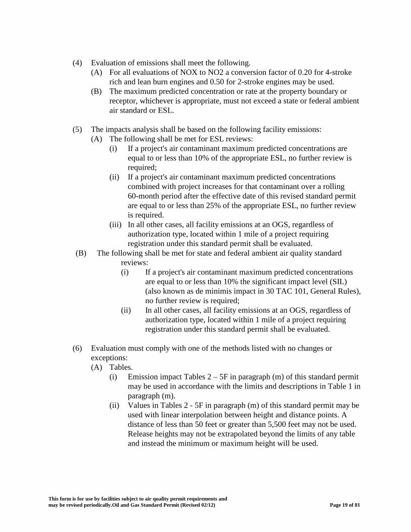
(4) Evaluation of emissions shall meet the following.
(A) For all evaluations of NOX to NO2 a conversion factor of 0.20 for 4-stroke rich and lean burn engines and 0.50 for 2-stroke engines may be used.
(B) The maximum predicted concentration or rate at the property boundary or receptor, whichever is appropriate, must not exceed a state or federal ambient air standard or ESL.
(5) The impacts analysis shall be based on the following facility emissions:
(A) The following shall be met for ESL reviews: (i) If a project's air contaminant maximum predicted concentrations are
equal to or less than 10% of the appropriate ESL, no further review is required;
(ii) If a project's air contaminant maximum predicted concentrations combined with project increases for that contaminant over a rolling 60-month period after the effective date of this revised standard permit are equal to or less than 25% of the appropriate ESL, no further review is required.
(iii) In all other cases, all facility emissions at an OGS, regardless of authorization type, located within 1 mile of a project requiring registration under this standard permit shall be evaluated.
(B) The following shall be met for state and federal ambient air quality standard reviews: (i) If a project's air contaminant maximum predicted concentrations
are equal to or less than 10% the significant impact level (SIL) (also known as de minimis impact in 30 TAC 101, General Rules), no further review is required;
(ii) In all other cases, all facility emissions at an OGS, regardless of authorization type, located within 1 mile of a project requiring registration under this standard permit shall be evaluated.
(6) Evaluation must comply with one of the methods listed with no changes or
exceptions: (A) Tables.
(i) Emission impact Tables 2 – 5F in paragraph (m) of this standard permit may be used in accordance with the limits and descriptions in Table 1 in paragraph (m).
(ii) Values in Tables 2 - 5F in paragraph (m) of this standard permit may be used with linear interpolation between height and distance points. A distance of less than 50 feet or greater than 5,500 feet may not be used. Release heights may not be extrapolated beyond the limits of any table and instead the minimum or maximum height will be used.
This form is for use by facilities subject to air quality permit requirements and may be revised periodically.Oil and Gas Standard Permit (Revised 02/12) Page 19 of 81

If distances and release heights are not interpolated, the next lowest height and lesser distances shall be used for determination of maximum acceptable emissions. All facilities exempted from the distance to the property line restriction in paragraph (e)(2) of this standard permit must use 50 feet as the distance to the property line for those ambient standards based on property line.
(B) Screening Modeling. A screening model may be used to demonstrate
acceptable emissions from an OGS under this standard permit if all of the parameters in the screening modeling protocol provided by the commission are met.
(C) Dispersion Modeling. A refined dispersion model may be used to demonstrate acceptable emissions from an OGS under this standard permit if all of the parameters in the refined dispersion modeling protocol provided by the commission are met.
(l) Existing, Unchanged Facilities and Projects Before Effective Date. The requirements
in 30 TAC §116.620 are applicable to existing unchanged facilities and new or changing facilities as specified in paragraph (a)(1) of this standard permit.
(m) The following Tables shall be used as required by this standard permit.
Table 1 Emission Impact Tables Limits and Descriptions; Table 2 Generic Modeling Results for Fugitives & Process Vents; Table 3 Generic Modeling Results for Flares and Thermal Destruction Devices Table 4 Generic Modeling Results for Blowdowns, Purging, and Pigging Table 5A Generic Modeling Results for Engines Less Than or Equal to 250 hp Table 5B Generic Modeling Results for Engines Greater Than 250 hp to Less Than or Equal to 500 hp Table 5C Generic Modeling Results for Engines Greater Than 500 hp to Less Than or Equal to 1000 hp Table 5D Generic Modeling Results for Engines Greater Than 1000 hp to Less Than or Equal to 1500 hp Table 5E Generic Modeling Results for Engines Greater Than 1500 hp to Less Than or Equal to 2000 hp Table 5F Generic Modeling Results for Engines Greater Than 2000 hp Table 6 Engine and Turbine Emission and Operational Standards Table 7 Sampling and Demonstrations of Compliance; Table 8 Monitoring and Records Demonstrations; Table 9 Fugitive Component Leak Detection and Repair (LDAR) Control Program ; and Table 10 Best Available Control Technology (BACT) Requirements
This form is for use by facilities subject to air quality permit requirements and may be revised periodically.Oil and Gas Standard Permit (Revised 02/12) Page 20 of 81

Table 1 Emission Impact Tables Limits and Descriptions
Topic Description Details
Variables EMAX HOURLY the maximum acceptable hourly (lb/hr) emissions for a specific air contaminant
EMAX ANNUAL the maximum acceptable annual (tpy) emissions for a specific air contaminant
P ambient air standard for a specific air contaminant (µg/m3 )
ESL current published effects screening level for a specific air contaminant (µg/m3)
G the most stringent of any applicable generic value from the Generic Modeling Results Tables at the emission point's release height and distance to property line (µg/m3/lb/hr)
WREPNx= weighted ratio of emissions of a specific air contaminant for each EPN divided by the sum of total emissions for all EPNs that emit that contaminant or (EEPNx/Etotal)
Single hourly ambient air emissions are determined by: EMAX HOURLY = P/G releases standard or co-located hourly health effects emissions are determined by: EMAX HOURLY = ESL/G groups of review similar releases annual ambient air emissions are determined by: EMAX ANNUAL = (8760/2000)
standard P/(0.08*G)
annual health effects emissions are determined by: EMAX ANNUAL = (8760/2000) review ESL/(0.08*G)
Multiple Limits If weighted ratios are not used, the total quantity of emissions shall release be assumed to be released from the most conservative applicable G points value at the site.
hourly ambient air emissions are determined by: EMAX HOURLY = (WREPN1) (P / GEPN1) standard + (WREPN2) (P / GEPN2) + (WREPNx) (P / GEPNx)
hourly health effects emissions are determined by: EMAX HOURLY = (WREPN1) (ESL review /GEPN1) + (WREPN2) (ESL/GEPN2) + .(WREPNx) (ESL / GEPNx)
annual ambient air emissions are determined by: EMAX ANNUAL = (8760/2000) standard [(WREPN1) (P / 0.08*GEPN1) + (WREPN2) (P / 0.08*GEPN2) +
(WREPNx) (P / 0.08*GEPNx)]
annual health effects emissions are determined by: EMAX ANNUAL = (8760/2000) review [(WREPN1) (ESL /0.08*GEPN1]) + (WREPN2) (ESL/0.08*GEPN2) +
WREPNx) (ESL / 0.08*GEPNx)]
This form is for use by facilities subject to air quality permit requirements and may be revised periodically.Oil and Gas Standard Permit (Revised 02/12) Page 21 of 81
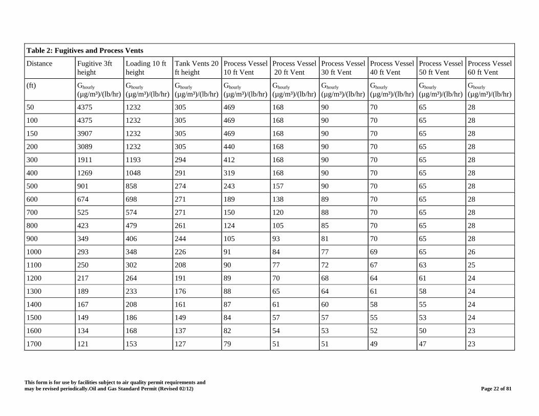
Table 2: Fugitives and Process Vents
Distance Fugitive height
3ft Loading height
10 ft Tank Vents 20 ft height
Process Vessel 10 ft Vent
Process Vessel 20 ft Vent
Process Vessel 30 ft Vent
Process Vessel 40 ft Vent
Process Vessel 50 ft Vent
Process Vessel 60 ft Vent
(ft) Ghourly (µg/m³)/(lb/hr)
Ghourly (µg/m³)/(lb/hr)
Ghourly (µg/m³)/(lb/hr)
Ghourly (µg/m³)/(lb/hr)
Ghourly (µg/m³)/(lb/hr)
Ghourly (µg/m³)/(lb/hr)
Ghourly (µg/m³)/(lb/hr)
Ghourly (µg/m³)/(lb/hr)
Ghourly (µg/m³)/(lb/hr)
50 4375 1232 305 469 168 90 70 65 28
100 4375 1232 305 469 168 90 70 65 28
150 3907 1232 305 469 168 90 70 65 28
200 3089 1232 305 440 168 90 70 65 28
300 1911 1193 294 412 168 90 70 65 28
400 1269 1048 291 319 168 90 70 65 28
500 901 858 274 243 157 90 70 65 28
600 674 698 271 189 138 89 70 65 28
700 525 574 271 150 120 88 70 65 28
800 423 479 261 124 105 85 70 65 28
900 349 406 244 105 93 81 70 65 28
1000 293 348 226 91 84 77 69 65 26
1100 250 302 208 90 77 72 67 63 25
1200 217 264 191 89 70 68 64 61 24
1300 189 233 176 88 65 64 61 58 24
1400 167 208 161 87 61 60 58 55 24
1500 149 186 149 84 57 57 55 53 24
1600 134 168 137 82 54 53 52 50 23
1700 121 153 127 79 51 51 49 47 23
This form is for use by facilities subject to air quality permit requirements and may be revised periodically.Oil and Gas Standard Permit (Revised 02/12) Page 22 of 81
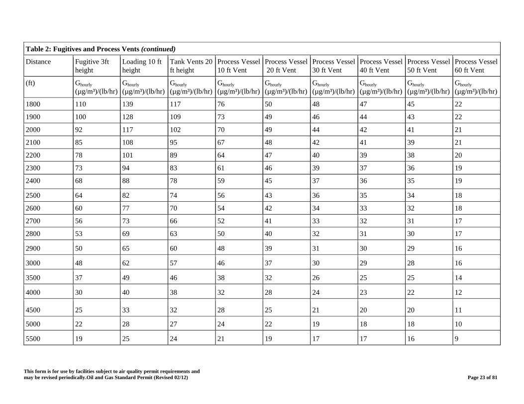
Table 2: Fugitives and Process Vents (continued)
Distance Fugitive height
3ft Loading height
10 ft Tank Vents 20 ft height
Process Vessel 10 ft Vent
Process Vessel 20 ft Vent
Process Vessel 30 ft Vent
Process Vessel 40 ft Vent
Process Vessel 50 ft Vent
Process Vessel 60 ft Vent
(ft) Ghourly (µg/m³)/(lb/hr)
Ghourly (µg/m³)/(lb/hr)
Ghourly (µg/m³)/(lb/hr)
Ghourly (µg/m³)/(lb/hr)
Ghourly (µg/m³)/(lb/hr)
Ghourly (µg/m³)/(lb/hr)
Ghourly (µg/m³)/(lb/hr)
Ghourly (µg/m³)/(lb/hr)
Ghourly (µg/m³)/(lb/hr)
1800 110 139 117 76 50 48 47 45 22
1900 100 128 109 73 49 46 44 43 22
2000 92 117 102 70 49 44 42 41 21
2100 85 108 95 67 48 42 41 39 21
2200 78 101 89 64 47 40 39 38 20
2300 73 94 83 61 46 39 37 36 19
2400 68 88 78 59 45 37 36 35 19
2500 64 82 74 56 43 36 35 34 18
2600 60 77 70 54 42 34 33 32 18
2700 56 73 66 52 41 33 32 31 17
2800 53 69 63 50 40 32 31 30 17
2900 50 65 60 48 39 31 30 29 16
3000 48 62 57 46 37 30 29 28 16
3500 37 49 46 38 32 26 25 25 14
4000 30 40 38 32 28 24 23 22 12
4500 25 33 32 28 25 21 20 20 11
5000 22 28 27 24 22 19 18 18 10
5500 19 25 24 21 19 17 17 16 9
This form is for use by facilities subject to air quality permit requirements and may be revised periodically.Oil and Gas Standard Permit (Revised 02/12) Page 23 of 81
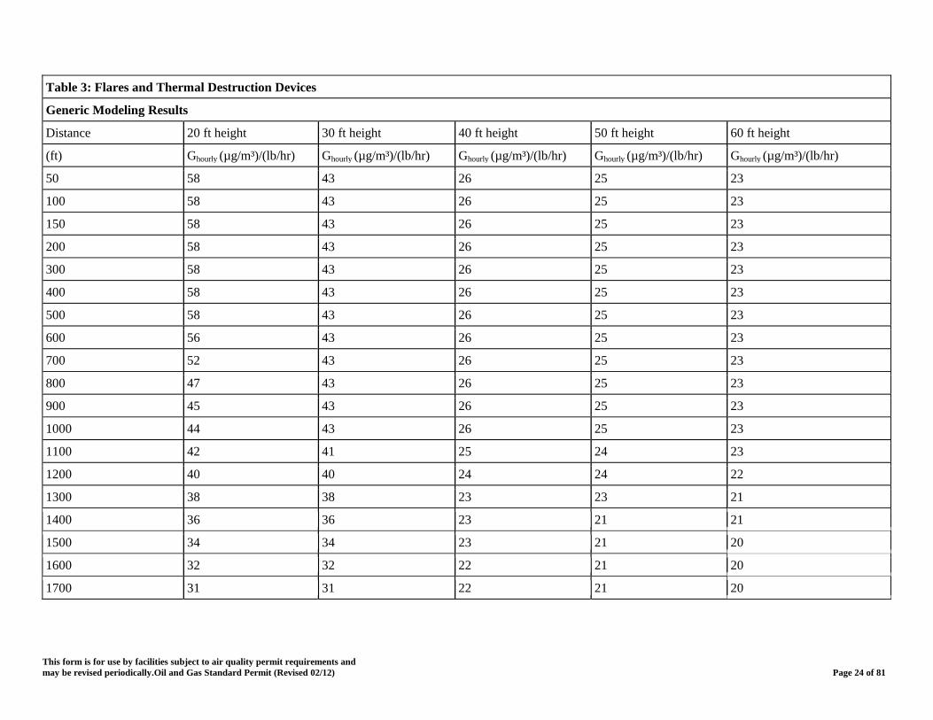
Table 3: Flares and Thermal Destruction Devices
Generic Modeling Results
Distance 20 ft height 30 ft height 40 ft height 50 ft height 60 ft height
(ft) Ghourly (µg/m³)/(lb/hr) Ghourly (µg/m³)/(lb/hr) Ghourly (µg/m³)/(lb/hr) Ghourly (µg/m³)/(lb/hr) Ghourly (µg/m³)/(lb/hr)
50 58 43 26 25 23
100 58 43 26 25 23
150 58 43 26 25 23
200 58 43 26 25 23
300 58 43 26 25 23
400 58 43 26 25 23
500 58 43 26 25 23
600 56 43 26 25 23
700 52 43 26 25 23
800 47 43 26 25 23
900 45 43 26 25 23
1000 44 43 26 25 23
1100 42 41 25 24 23
1200 40 40 24 24 22
1300 38 38 23 23 21
1400 36 36 23 21 21
1500 34 34 23 21 20
1600 32 32 22 21 20
1700 31 31 22 21 20
This form is for use by facilities subject to air quality permit requirements and may be revised periodically.Oil and Gas Standard Permit (Revised 02/12) Page 24 of 81
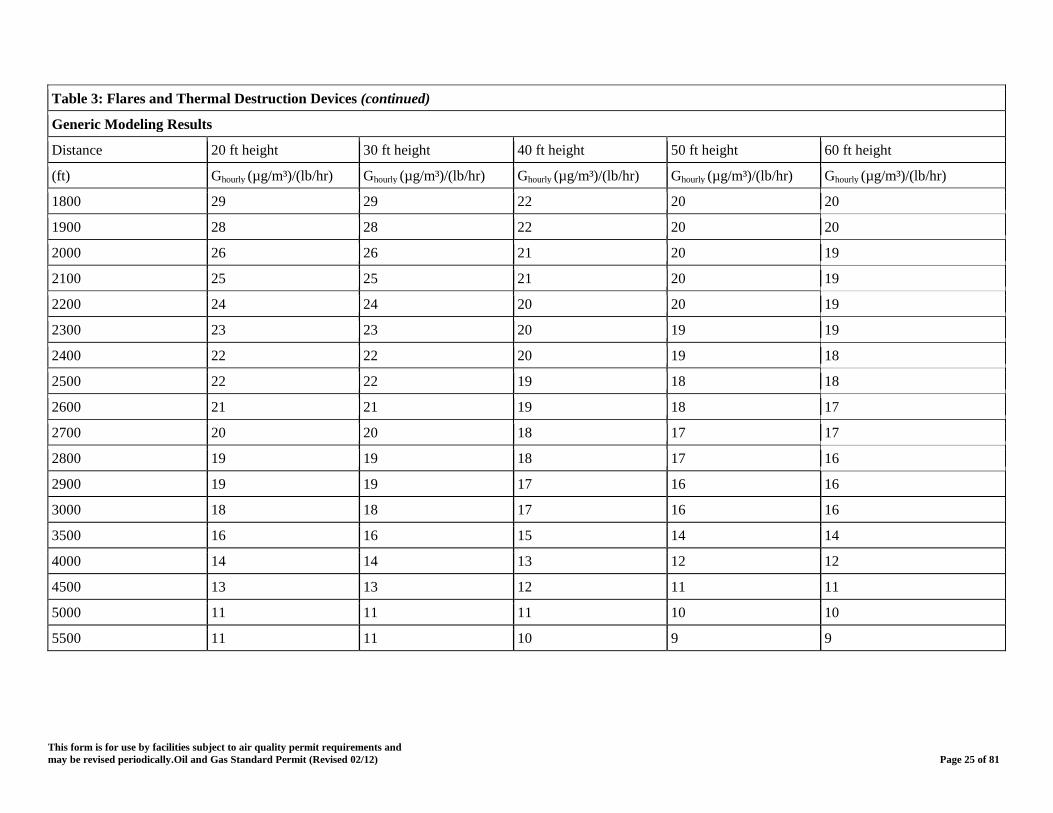
Table 3: Flares and Thermal Destruction Devices (continued)
Generic Modeling Results
Distance 20 ft height 30 ft height 40 ft height 50 ft height 60 ft height
(ft) Ghourly (µg/m³)/(lb/hr) Ghourly (µg/m³)/(lb/hr) Ghourly (µg/m³)/(lb/hr) Ghourly (µg/m³)/(lb/hr) Ghourly (µg/m³)/(lb/hr)
1800 29 29 22 20 20
1900 28 28 22 20 20
2000 26 26 21 20 19
2100 25 25 21 20 19
2200 24 24 20 20 19
2300 23 23 20 19 19
2400 22 22 20 19 18
2500 22 22 19 18 18
2600 21 21 19 18 17
2700 20 20 18 17 17
2800 19 19 18 17 16
2900 19 19 17 16 16
3000 18 18 17 16 16
3500 16 16 15 14 14
4000 14 14 13 12 12
4500 13 13 12 11 11
5000 11 11 11 10 10
5500 11 11 10 9 9
This form is for use by facilities subject to air quality permit requirements and may be revised periodically.Oil and Gas Standard Permit (Revised 02/12) Page 25 of 81

Table 4: Blowdowns, Purging, and Pigging Generic Modeling Results
Distance < 30 psig; 3 ft height < 30 psig; 10 ft height < 30 psig; 20 ft height ≥ 30 psig; 6 ft height ≥ 30 psig; 10 ft height
(ft) Ghourly (µg/m³)/(lb/hr) Ghourly (µg/m³)/(lb/hr) Ghourly (µg/m³)/(lb/hr) Ghourly (µg/m³)/(lb/hr) Ghourly (µg/m³)/(lb/hr)
50 4304 791 244 51 25
100 4304 791 244 51 25
150 4250 777 244 51 25
200 3621 763 244 51 25
300 2367 750 225 51 25
400 1607 737 225 51 25
500 1156 671 224 51 25
600 871 581 218 48 25
700 682 498 212 44 25
800 551 427 210 40 24
900 456 368 204 36 23
1000 384 320 194 33 21
1100 328 281 182 30 20
1200 284 248 170 28 18
1300 249 221 159 27 17
1400 220 198 147 27 16
1500 196 178 137 27 15
1600 176 162 127 27 14
1700 159 147 118 27 13
1800 145 135 110 27 13
This form is for use by facilities subject to air quality permit requirements and may be revised periodically.Oil and Gas Standard Permit (Revised 02/12) Page 26 of 81
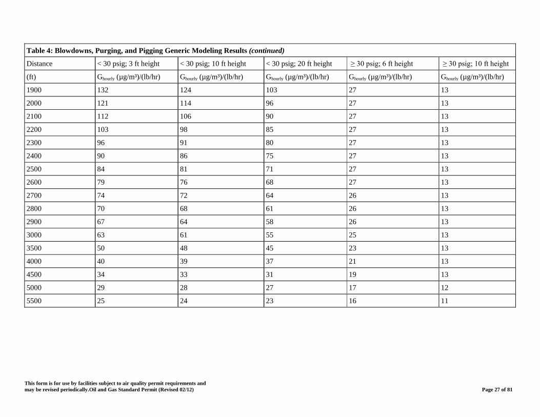
Table 4: Blowdowns, Purging, and Pigging Generic Modeling Results (continued)
Distance < 30 psig; 3 ft height < 30 psig; 10 ft height < 30 psig; 20 ft height ≥ 30 psig; 6 ft height ≥ 30 psig; 10 ft height
(ft) Ghourly (µg/m³)/(lb/hr) Ghourly (µg/m³)/(lb/hr) Ghourly (µg/m³)/(lb/hr) Ghourly (µg/m³)/(lb/hr) Ghourly (µg/m³)/(lb/hr)
1900 132 124 103 27 13
2000 121 114 96 27 13
2100 112 106 90 27 13
2200 103 98 85 27 13
2300 96 91 80 27 13
2400 90 86 75 27 13
2500 84 81 71 27 13
2600 79 76 68 27 13
2700 74 72 64 26 13
2800 70 68 61 26 13
2900 67 64 58 26 13
3000 63 61 55 25 13
3500 50 48 45 23 13
4000 40 39 37 21 13
4500 34 33 31 19 13
5000 29 28 27 17 12
5500 25 24 23 16 11
This form is for use by facilities subject to air quality permit requirements and may be revised periodically.Oil and Gas Standard Permit (Revised 02/12) Page 27 of 81

Table 5A Engines Less Than or Equal to 250 hp
Generic Modeling Results
Distance 8 ft height 10 ft height 12 ft height 14 ft height 16 ft height 18 ft height 20 ft height 25 ft height 30 ft height 35 ft height 40 ft height
(ft) Ghourly (µg/m³)/(lb/hr)
Ghourly (µg/m³)/(lb/hr)
Ghourly (µg/m³)/(lb/hr)
Ghourly (µg/m³)/(lb/hr)
Ghourly (µg/m³)/(lb/hr)
Ghourly (µg/m³)/(lb/hr)
Ghourly (µg/m³)/(lb/hr)
Ghourly (µg/m³)/(lb/hr)
Ghourly (µg/m³)/(lb/hr)
Ghourly (µg/m³)/(lb/hr)
Ghourly (µg/m³)/(lb/hr)
50 97 85 83 81 81 71 58 44 43 36 26
100 97 85 83 81 81 71 58 44 43 36 26
150 97 85 83 81 81 71 58 44 43 36 26
200 93 85 83 81 81 71 58 44 43 36 26
300 92 85 83 81 81 71 58 44 43 36 26
400 91 85 83 81 81 71 58 44 43 36 26
500 88 85 83 81 81 71 58 44 43 36 26
600 80 79 78 78 78 70 56 44 43 36 26
700 78 77 76 76 71 68 52 44 43 36 26
800 76 75 74 74 64 63 47 44 43 36 26
900 74 73 72 72 58 58 45 44 43 36 26
1000 72 71 71 71 53 53 44 43 43 36 26
1100 69 69 69 69 49 49 42 42 41 35 25
1200 66 66 66 65 45 45 40 40 40 35 24
1300 62 62 62 62 42 42 38 38 38 33 23
This form is for use by facilities subject to air quality permit requirements and may be revised periodically.Oil and Gas Standard Permit (Revised 02/12) Page 28 of 81
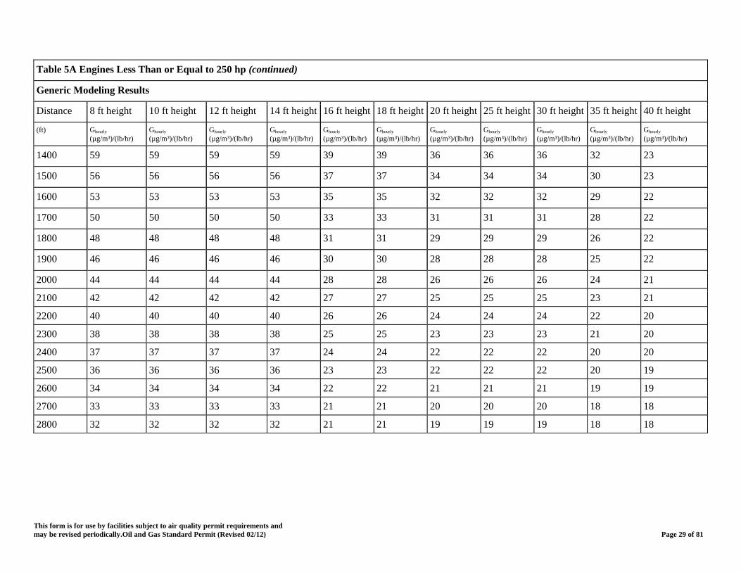
Table 5A Engines Less Than or Equal to 250 hp (continued)
Generic Modeling Results
Distance 8 ft height 10 ft height 12 ft height 14 ft height 16 ft height 18 ft height 20 ft height 25 ft height 30 ft height 35 ft height 40 ft height
(ft) Ghourly (µg/m³)/(lb/hr)
Ghourly (µg/m³)/(lb/hr)
Ghourly (µg/m³)/(lb/hr)
Ghourly (µg/m³)/(lb/hr)
Ghourly (µg/m³)/(lb/hr)
Ghourly (µg/m³)/(lb/hr)
Ghourly (µg/m³)/(lb/hr)
Ghourly (µg/m³)/(lb/hr)
Ghourly (µg/m³)/(lb/hr)
Ghourly (µg/m³)/(lb/hr)
Ghourly (µg/m³)/(lb/hr)
1400 59 59 59 59 39 39 36 36 36 32 23
1500 56 56 56 56 37 37 34 34 34 30 23
1600 53 53 53 53 35 35 32 32 32 29 22
1700 50 50 50 50 33 33 31 31 31 28 22
1800 48 48 48 48 31 31 29 29 29 26 22
1900 46 46 46 46 30 30 28 28 28 25 22
2000 44 44 44 44 28 28 26 26 26 24 21
2100 42 42 42 42 27 27 25 25 25 23 21
2200 40 40 40 40 26 26 24 24 24 22 20
2300 38 38 38 38 25 25 23 23 23 21 20
2400 37 37 37 37 24 24 22 22 22 20 20
2500 36 36 36 36 23 23 22 22 22 20 19
2600 34 34 34 34 22 22 21 21 21 19 19
2700 33 33 33 33 21 21 20 20 20 18 18
2800 32 32 32 32 21 21 19 19 19 18 18
This form is for use by facilities subject to air quality permit requirements and may be revised periodically.Oil and Gas Standard Permit (Revised 02/12) Page 29 of 81
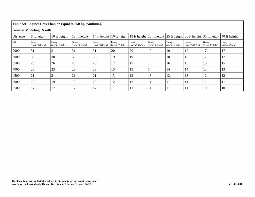
Table 5A Engines Less Than or Equal to 250 hp (continued)
Generic Modeling Results
Distance 8 ft height 10 ft height 12 ft height 14 ft height 16 ft height 18 ft height 20 ft height 25 ft height 30 ft height 35 ft height 40 ft height (ft) Ghourly
(µg/m³)/(lb/hr) Ghourly (µg/m³)/(lb/hr)
Ghourly (µg/m³)/(lb/hr)
Ghourly (µg/m³)/(lb/hr)
Ghourly (µg/m³)/(lb/hr)
Ghourly (µg/m³)/(lb/hr)
Ghourly (µg/m³)/(lb/hr)
Ghourly (µg/m³)/(lb/hr)
Ghourly (µg/m³)/(lb/hr)
Ghourly (µg/m³)/(lb/hr)
Ghourly (µg/m³)/(lb/hr)
2900 31 31 31 31 20 20 19 19 19 17 17
3000 30 30 30 30 19 19 18 18 18 17 17
3500 26 26 26 26 17 17 16 16 16 15 15
4000 23 23 23 23 15 15 14 14 14 13 13
4500 21 21 21 21 13 13 13 13 13 12 12
5000 19 19 19 19 12 12 11 11 11 11 11
5500 17 17 17 17 11 11 11 11 11 10 10
This form is for use by facilities subject to air quality permit requirements and may be revised periodically.Oil and Gas Standard Permit (Revised 02/12) Page 30 of 81
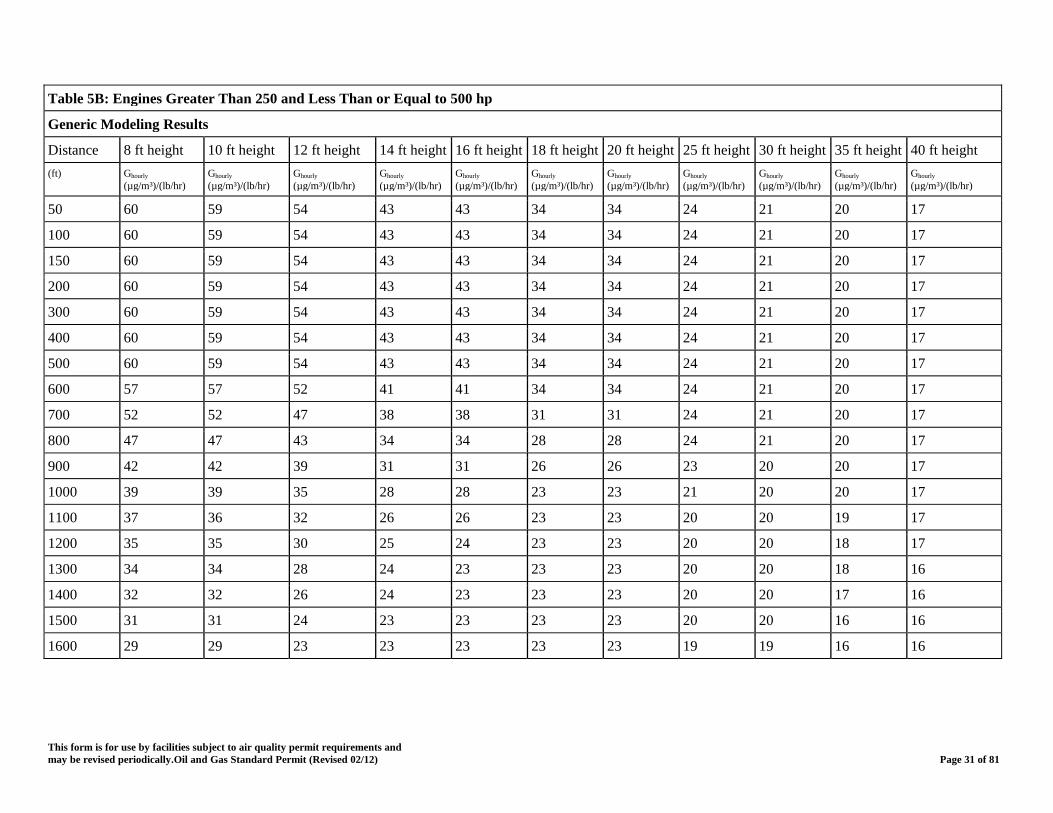
Table 5B: Engines Greater Than 250 and Less Than or Equal to 500 hp
Generic Modeling Results
Distance 8 ft height 10 ft height 12 ft height 14 ft height 16 ft height 18 ft height 20 ft height 25 ft height 30 ft height 35 ft height 40 ft height (ft) Ghourly
(µg/m³)/(lb/hr) Ghourly (µg/m³)/(lb/hr)
Ghourly (µg/m³)/(lb/hr)
Ghourly (µg/m³)/(lb/hr)
Ghourly (µg/m³)/(lb/hr)
Ghourly (µg/m³)/(lb/hr)
Ghourly (µg/m³)/(lb/hr)
Ghourly (µg/m³)/(lb/hr)
Ghourly (µg/m³)/(lb/hr)
Ghourly (µg/m³)/(lb/hr)
Ghourly (µg/m³)/(lb/hr)
50 60 59 54 43 43 34 34 24 21 20 17
100 60 59 54 43 43 34 34 24 21 20 17
150 60 59 54 43 43 34 34 24 21 20 17
200 60 59 54 43 43 34 34 24 21 20 17
300 60 59 54 43 43 34 34 24 21 20 17
400 60 59 54 43 43 34 34 24 21 20 17
500 60 59 54 43 43 34 34 24 21 20 17
600 57 57 52 41 41 34 34 24 21 20 17
700 52 52 47 38 38 31 31 24 21 20 17
800 47 47 43 34 34 28 28 24 21 20 17
900 42 42 39 31 31 26 26 23 20 20 17
1000 39 39 35 28 28 23 23 21 20 20 17
1100 37 36 32 26 26 23 23 20 20 19 17
1200 35 35 30 25 24 23 23 20 20 18 17
1300 34 34 28 24 23 23 23 20 20 18 16
1400 32 32 26 24 23 23 23 20 20 17 16
1500 31 31 24 23 23 23 23 20 20 16 16
1600 29 29 23 23 23 23 23 19 19 16 16
This form is for use by facilities subject to air quality permit requirements and may be revised periodically.Oil and Gas Standard Permit (Revised 02/12) Page 31 of 81
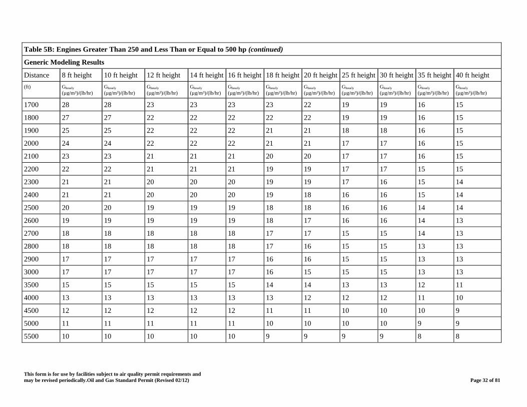
Table 5B: Engines Greater Than 250 and Less Than or Equal to 500 hp (continued)
Generic Modeling Results
Distance 8 ft height 10 ft height 12 ft height 14 ft height 16 ft height 18 ft height 20 ft height 25 ft height 30 ft height 35 ft height 40 ft height (ft) Ghourly
(µg/m³)/(lb/hr) Ghourly (µg/m³)/(lb/hr)
Ghourly (µg/m³)/(lb/hr)
Ghourly (µg/m³)/(lb/hr)
Ghourly (µg/m³)/(lb/hr)
Ghourly (µg/m³)/(lb/hr)
Ghourly (µg/m³)/(lb/hr)
Ghourly (µg/m³)/(lb/hr)
Ghourly (µg/m³)/(lb/hr)
Ghourly (µg/m³)/(lb/hr)
Ghourly (µg/m³)/(lb/hr)
1700 28 28 23 23 23 23 22 19 19 16 15
1800 27 27 22 22 22 22 22 19 19 16 15
1900 25 25 22 22 22 21 21 18 18 16 15
2000 24 24 22 22 22 21 21 17 17 16 15
2100 23 23 21 21 21 20 20 17 17 16 15
2200 22 22 21 21 21 19 19 17 17 15 15
2300 21 21 20 20 20 19 19 17 16 15 14
2400 21 21 20 20 20 19 18 16 16 15 14
2500 20 20 19 19 19 18 18 16 16 14 14
2600 19 19 19 19 19 18 17 16 16 14 13
2700 18 18 18 18 18 17 17 15 15 14 13
2800 18 18 18 18 18 17 16 15 15 13 13
2900 17 17 17 17 17 16 16 15 15 13 13
3000 17 17 17 17 17 16 15 15 15 13 13
3500 15 15 15 15 15 14 14 13 13 12 11
4000 13 13 13 13 13 13 12 12 12 11 10
4500 12 12 12 12 12 11 11 10 10 10 9
5000 11 11 11 11 11 10 10 10 10 9 9
5500 10 10 10 10 10 9 9 9 9 8 8
This form is for use by facilities subject to air quality permit requirements and may be revised periodically.Oil and Gas Standard Permit (Revised 02/12) Page 32 of 81
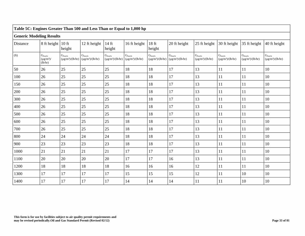
Table 5C: Engines Greater Than 500 and Less Than or Equal to 1,000 hp
Generic Modeling Results
Distance 8 ft height 10 ft height
12 ft height 14 ft height
16 ft height 18 ft height
20 ft height 25 ft height 30 ft height 35 ft height 40 ft height
(ft) Ghourly (µg/m³)/ (lb/hr)
Ghourly (µg/m³)/(lb/hr)
Ghourly (µg/m³)/(lb/hr)
Ghourly (µg/m³)/(lb/hr)
Ghourly (µg/m³)/(lb/hr)
Ghourly (µg/m³)/(lb/hr)
Ghourly (µg/m³)/(lb/hr)
Ghourly (µg/m³)/(lb/hr)
Ghourly (µg/m³)/(lb/hr)
Ghourly (µg/m³)/(lb/hr)
Ghourly (µg/m³)/(lb/hr)
50 26 25 25 25 18 18 17 13 11 11 10
100 26 25 25 25 18 18 17 13 11 11 10
150 26 25 25 25 18 18 17 13 11 11 10
200 26 25 25 25 18 18 17 13 11 11 10
300 26 25 25 25 18 18 17 13 11 11 10
400 26 25 25 25 18 18 17 13 11 11 10
500 26 25 25 25 18 18 17 13 11 11 10
600 26 25 25 25 18 18 17 13 11 11 10
700 26 25 25 25 18 18 17 13 11 11 10
800 24 24 24 24 18 18 17 13 11 11 10
900 23 23 23 23 18 18 17 13 11 11 10
1000 21 21 21 21 17 17 17 13 11 11 10
1100 20 20 20 20 17 17 16 13 11 11 10
1200 18 18 18 18 16 16 16 12 11 11 10
1300 17 17 17 17 15 15 15 12 11 10 10
1400 17 17 17 17 14 14 14 11 11 10 10
This form is for use by facilities subject to air quality permit requirements and may be revised periodically.Oil and Gas Standard Permit (Revised 02/12) Page 33 of 81

Table 5C: Engines Greater Than 500 and Less Than or Equal to 1,000 hp (continued)
Generic Modeling Results
Distance 8 ft height 10 ft height
12 ft height 14 ft height
16 ft height 18 ft height
20 ft height 25 ft height 30 ft height 35 ft height 40 ft height
(ft) Ghourly (µg/m³)/ (lb/hr)
Ghourly (µg/m³)/(lb/hr)
Ghourly (µg/m³)/(lb/hr)
Ghourly (µg/m³)/(lb/hr)
Ghourly (µg/m³)/(lb/hr)
Ghourly (µg/m³)/(lb/hr)
Ghourly (µg/m³)/(lb/hr)
Ghourly (µg/m³)/(lb/hr)
Ghourly (µg/m³)/(lb/hr)
Ghourly (µg/m³)/(lb/hr)
Ghourly (µg/m³)/(lb/hr)
1500 17 17 16 16 13 13 13 11 11 10 9
1600 17 17 16 16 13 13 13 11 11 10 9
1700 16 16 15 15 13 12 12 11 11 9 9
1800 16 16 15 15 13 12 12 11 11 9 9
1900 15 15 14 14 13 12 12 11 10 9 9
2000 15 15 14 14 13 12 12 11 10 9 9
2100 14 14 13 13 12 12 12 11 10 9 9
2200 14 14 13 13 12 12 12 10 10 9 9
2300 13 13 12 12 12 11 11 10 10 9 8
2400 13 13 12 12 12 11 11 10 9 9 8
2500 12 12 12 12 11 11 11 10 9 9 8
2600 12 12 11 11 11 11 11 10 9 9 8
2700 12 12 11 11 11 10 10 10 9 8 8
2800 11 11 11 11 11 10 10 9 9 8 8
2900 11 11 10 10 10 10 10 9 9 8 8
3000 11 11 10 10 10 10 10 9 9 8 8
3500 9 9 9 9 9 9 9 8 8 7 7
This form is for use by facilities subject to air quality permit requirements and may be revised periodically.Oil and Gas Standard Permit (Revised 02/12) Page 34 of 81
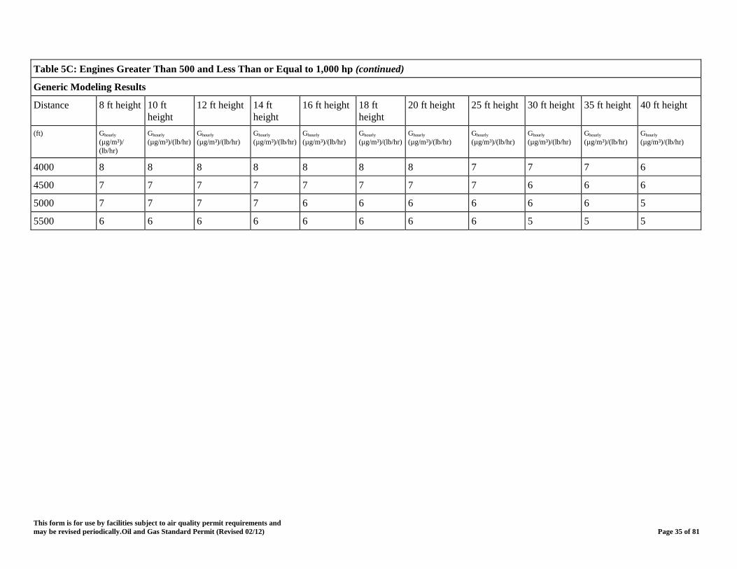
Table 5C: Engines Greater Than 500 and Less Than or Equal to 1,000 hp (continued)
Generic Modeling Results
Distance 8 ft height 10 ft height
12 ft height 14 ft height
16 ft height 18 ft height
20 ft height 25 ft height 30 ft height 35 ft height 40 ft height
(ft) Ghourly (µg/m³)/ (lb/hr)
Ghourly (µg/m³)/(lb/hr)
Ghourly (µg/m³)/(lb/hr)
Ghourly (µg/m³)/(lb/hr)
Ghourly (µg/m³)/(lb/hr)
Ghourly (µg/m³)/(lb/hr)
Ghourly (µg/m³)/(lb/hr)
Ghourly (µg/m³)/(lb/hr)
Ghourly (µg/m³)/(lb/hr)
Ghourly (µg/m³)/(lb/hr)
Ghourly (µg/m³)/(lb/hr)
4000 8 8 8 8 8 8 8 7 7 7 6
4500 7 7 7 7 7 7 7 7 6 6 6
5000 7 7 7 7 6 6 6 6 6 6 5
5500 6 6 6 6 6 6 6 6 5 5 5
This form is for use by facilities subject to air quality permit requirements and may be revised periodically.Oil and Gas Standard Permit (Revised 02/12) Page 35 of 81

Table 5D: Engines Greater Than 1,000 and Less Than or Equal to 1,500 hp
Generic Modeling Results
Distance 8 ft height 10 ft height
12 ft height 14 ft height
16 ft height 18 ft height
20 ft height 25 ft height 30 ft height 35 ft height 40 ft height
(ft) Ghourly (µg/m³)/ (lb/hr)
Ghourly (µg/m³)/(lb/hr)
Ghourly (µg/m³)/(lb/hr)
Ghourly (µg/m³)/(lb/hr)
Ghourly (µg/m³)/(lb/hr)
Ghourly (µg/m³)/(lb/hr)
Ghourly (µg/m³)/(lb/hr)
Ghourly (µg/m³)/(lb/hr)
Ghourly (µg/m³)/(lb/hr)
Ghourly (µg/m³)/(lb/hr)
Ghourly (µg/m³)/(lb/hr)
50 17 13 12 10 10 10 10 9 8 8 7
100 17 13 12 10 10 10 10 9 8 8 7
150 17 13 12 10 10 10 10 9 8 8 7
200 17 13 12 10 10 10 10 9 8 8 7
300 17 13 12 10 10 10 10 9 8 8 7
400 17 13 11 10 10 10 10 9 8 8 7
500 17 13 11 10 10 10 10 9 8 8 7
600 17 12 11 10 10 10 10 9 8 8 7
700 17 11 11 10 10 10 10 9 8 8 7
800 17 11 11 10 10 10 10 9 8 8 7
900 17 11 11 10 10 10 10 9 8 8 7
1000 17 11 11 10 10 10 10 9 8 8 7
1100 16 11 11 10 10 10 10 9 8 8 7
1200 15 10 10 10 9 9 9 9 8 7 7
1300 15 10 10 10 9 9 9 8 8 7 7
1400 14 10 10 10 9 9 8 8 8 7 7
This form is for use by facilities subject to air quality permit requirements and may be revised periodically.Oil and Gas Standard Permit (Revised 02/12) Page 36 of 81
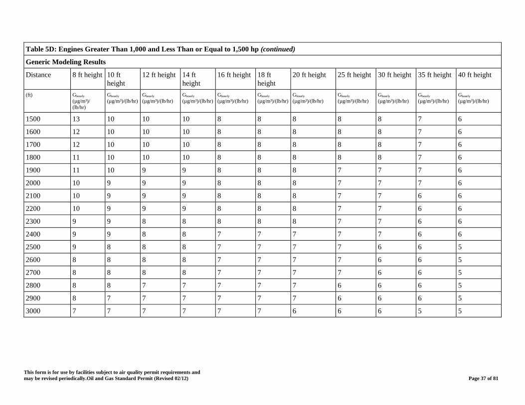
Table 5D: Engines Greater Than 1,000 and Less Than or Equal to 1,500 hp (continued)
Generic Modeling Results
Distance 8 ft height 10 ft 12 ft height 14 ft 16 ft height 18 ft 20 ft height 25 ft height 30 ft height 35 ft height 40 ft height height height height
(ft) Ghourly Ghourly Ghourly Ghourly Ghourly Ghourly Ghourly Ghourly Ghourly Ghourly Ghourly (µg/m³)/ (µg/m³)/(lb/hr) (µg/m³)/(lb/hr) (µg/m³)/(lb/hr) (µg/m³)/(lb/hr) (µg/m³)/(lb/hr) (µg/m³)/(lb/hr) (µg/m³)/(lb/hr) (µg/m³)/(lb/hr) (µg/m³)/(lb/hr) (µg/m³)/(lb/hr) (lb/hr)
1500 13 10 10 10 8 8 8 8 8 7 6
1600 12 10 10 10 8 8 8 8 8 7 6
1700 12 10 10 10 8 8 8 8 8 7 6
1800 11 10 10 10 8 8 8 8 8 7 6
1900 11 10 9 9 8 8 8 7 7 7 6
2000 10 9 9 9 8 8 8 7 7 7 6
2100 10 9 9 9 8 8 8 7 7 6 6
2200 10 9 9 9 8 8 8 7 7 6 6
2300 9 9 8 8 8 8 8 7 7 6 6
2400 9 9 8 8 7 7 7 7 7 6 6
2500 9 8 8 8 7 7 7 7 6 6 5
2600 8 8 8 8 7 7 7 7 6 6 5
2700 8 8 8 8 7 7 7 7 6 6 5
2800 8 8 7 7 7 7 7 6 6 6 5
2900 8 7 7 7 7 7 7 6 6 6 5
3000 7 7 7 7 7 7 6 6 6 5 5
This form is for use by facilities subject to air quality permit requirements and may be revised periodically.Oil and Gas Standard Permit (Revised 02/12) Page 37 of 81
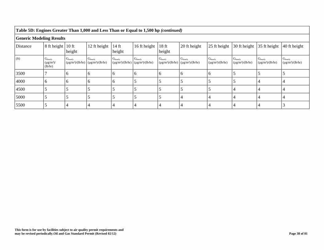
Table 5D: Engines Greater Than 1,000 and Less Than or Equal to 1,500 hp (continued)
Generic Modeling Results
Distance 8 ft height 10 ft height
12 ft height 14 ft height
16 ft height 18 ft height
20 ft height 25 ft height 30 ft height 35 ft height 40 ft height
(ft) Ghourly (µg/m³)/ (lb/hr)
Ghourly (µg/m³)/(lb/hr)
Ghourly (µg/m³)/(lb/hr)
Ghourly (µg/m³)/(lb/hr)
Ghourly (µg/m³)/(lb/hr)
Ghourly (µg/m³)/(lb/hr)
Ghourly (µg/m³)/(lb/hr)
Ghourly (µg/m³)/(lb/hr)
Ghourly (µg/m³)/(lb/hr)
Ghourly (µg/m³)/(lb/hr)
Ghourly (µg/m³)/(lb/hr)
3500 7 6 6 6 6 6 6 6 5 5 5
4000 6 6 6 6 5 5 5 5 5 4 4
4500 5 5 5 5 5 5 5 5 4 4 4
5000 5 5 5 5 5 5 4 4 4 4 4
5500 5 4 4 4 4 4 4 4 4 4 3
This form is for use by facilities subject to air quality permit requirements and may be revised periodically.Oil and Gas Standard Permit (Revised 02/12) Page 38 of 81
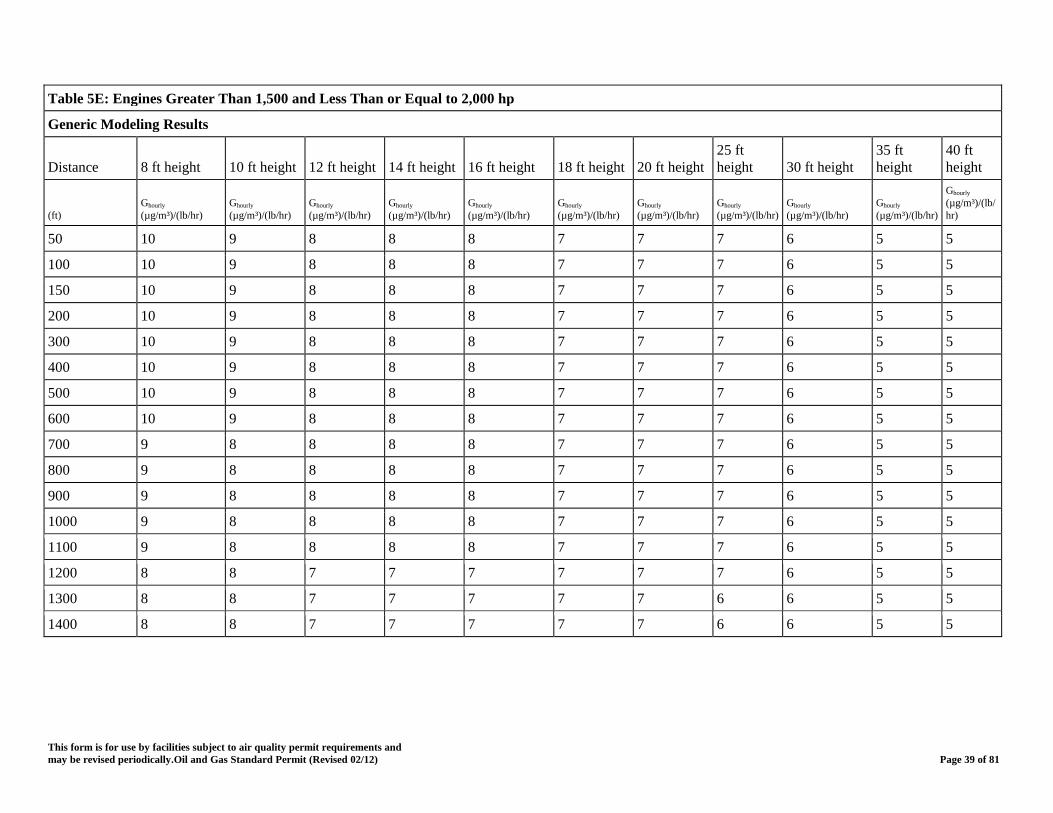
Table 5E: Engines Greater Than 1,500 and Less Than or Equal to 2,000 hp
Generic Modeling Results
Distance 8 ft height 10 ft height 12 ft height 14 ft height 16 ft height 18 ft height 20 ft height 25 ft height 30 ft height
35 ft height
40 ft height
(ft) Ghourly (µg/m³)/(lb/hr)
Ghourly (µg/m³)/(lb/hr)
Ghourly (µg/m³)/(lb/hr)
Ghourly (µg/m³)/(lb/hr)
Ghourly (µg/m³)/(lb/hr)
Ghourly (µg/m³)/(lb/hr)
Ghourly (µg/m³)/(lb/hr)
Ghourly (µg/m³)/(lb/hr)
Ghourly (µg/m³)/(lb/hr)
Ghourly (µg/m³)/(lb/hr)
Ghourly (µg/m³)/(lb/hr)
50 10 9 8 8 8 7 7 7 6 5 5
100 10 9 8 8 8 7 7 7 6 5 5
150 10 9 8 8 8 7 7 7 6 5 5
200 10 9 8 8 8 7 7 7 6 5 5
300 10 9 8 8 8 7 7 7 6 5 5
400 10 9 8 8 8 7 7 7 6 5 5
500 10 9 8 8 8 7 7 7 6 5 5
600 10 9 8 8 8 7 7 7 6 5 5
700 9 8 8 8 8 7 7 7 6 5 5
800 9 8 8 8 8 7 7 7 6 5 5
900 9 8 8 8 8 7 7 7 6 5 5
1000 9 8 8 8 8 7 7 7 6 5 5
1100 9 8 8 8 8 7 7 7 6 5 5
1200 8 8 7 7 7 7 7 7 6 5 5
1300 8 8 7 7 7 7 7 6 6 5 5
1400 8 8 7 7 7 7 7 6 6 5 5
This form is for use by facilities subject to air quality permit requirements and may be revised periodically.Oil and Gas Standard Permit (Revised 02/12) Page 39 of 81
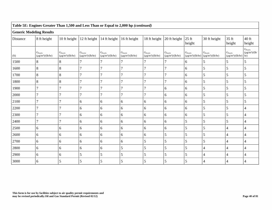
Table 5E: Engines Greater Than 1,500 and Less Than or Equal to 2,000 hp (continued)
Generic Modeling Results
Distance 8 ft height 10 ft height 12 ft height 14 ft height 16 ft height 18 ft height 20 ft height 25 ft height
30 ft height 35 ft height
40 ft height
(ft) Ghourly (µg/m³)/(lb/hr)
Ghourly (µg/m³)/(lb/hr)
Ghourly (µg/m³)/(lb/hr)
Ghourly (µg/m³)/(lb/hr)
Ghourly (µg/m³)/(lb/hr)
Ghourly (µg/m³)/(lb/hr)
Ghourly (µg/m³)/(lb/hr)
Ghourly (µg/m³)/(lb/hr)
Ghourly (µg/m³)/(lb/hr)
Ghourly (µg/m³)/(lb/hr)
Ghourly (µg/m³)/(lb/hr)
1500 8 8 7 7 7 7 7 6 5 5 5
1600 8 8 7 7 7 7 7 6 5 5 5
1700 8 8 7 7 7 7 7 6 5 5 5
1800 8 8 7 7 7 7 7 6 5 5 5
1900 7 7 7 7 7 7 6 6 5 5 5
2000 7 7 7 7 7 7 6 6 5 5 5
2100 7 7 6 6 6 6 6 6 5 5 5
2200 7 7 6 6 6 6 6 6 5 5 4
2300 7 7 6 6 6 6 6 6 5 5 4
2400 7 7 6 6 6 6 6 5 5 5 4
2500 6 6 6 6 6 6 6 5 5 4 4
2600 6 6 6 6 6 6 5 5 5 4 4
2700 6 6 6 6 6 5 5 5 5 4 4
2800 6 6 6 6 5 5 5 5 4 4 4
2900 6 6 5 5 5 5 5 5 4 4 4
3000 6 5 5 5 5 5 5 5 4 4 4
This form is for use by facilities subject to air quality permit requirements and may be revised periodically.Oil and Gas Standard Permit (Revised 02/12) Page 40 of 81

Table 5E: Engines Greater Than 1,500 and Less Than or Equal to 2,000 hp (continued)
Generic Modeling Results
Distance 8 ft height 10 ft height 12 ft height 14 ft height 16 ft height 18 ft height 20 ft height 25 ft height
30 ft height 35 ft height
40 ft height
(ft) Ghourly (µg/m³)/(lb/hr)
Ghourly (µg/m³)/(lb/hr)
Ghourly (µg/m³)/(lb/hr)
Ghourly (µg/m³)/(lb/hr)
Ghourly (µg/m³)/(lb/hr)
Ghourly (µg/m³)/(lb/hr)
Ghourly (µg/m³)/(lb/hr)
Ghourly (µg/m³)/(lb/hr)
Ghourly (µg/m³)/(lb/hr)
Ghourly (µg/m³)/(lb/hr)
Ghourly (µg/m³)/(lb/hr)
3500 5 5 5 5 5 4 4 4 4 4 3
4000 4 4 4 4 4 4 4 4 4 3 3
4500 4 4 4 4 4 4 4 3 3 3 3
5000 4 4 4 3 3 3 3 3 3 3 3
5500 3 3 3 3 3 3 3 3 3 3 3
This form is for use by facilities subject to air quality permit requirements and may be revised periodically.Oil and Gas Standard Permit (Revised 02/12) Page 41 of 81

Table 5F: Engines Greater Than 2,000 hp
Generic Modeling Results
Distance 8 ft height 10 ft height 12 ft height 14 ft height 16 ft height 18 ft height 20 ft height 25 ft height
30 ft height 35 ft height
40 ft height
(ft) Ghourly (µg/m³)/(lb/hr)
Ghourly (µg/m³)/(lb/hr)
Ghourly (µg/m³)/(lb/hr)
Ghourly (µg/m³)/(lb/hr)
Ghourly (µg/m³)/(lb/hr)
Ghourly (µg/m³)/(lb/hr)
Ghourly (µg/m³)/(lb/hr)
Ghourly (µg/m³)/(lb/hr)
Ghourly (µg/m³)/(lb/hr)
Ghourly (µg/m³)/(lb/hr)
Ghourly (µg/m³)/(lb/hr)
50 7 6 6 6 5 5 5 5 4 4 4
100 7 6 6 6 5 5 5 5 4 4 4
150 7 6 6 6 5 5 5 5 4 4 4
200 7 6 6 6 5 5 5 5 4 4 4
300 7 6 6 6 5 5 5 5 4 4 4
400 7 6 6 6 5 5 5 5 4 4 4
500 7 6 6 6 5 5 5 5 4 4 4
600 7 6 6 6 5 5 5 5 4 4 4
700 7 6 6 6 5 5 5 5 4 4 4
800 6 6 6 6 5 5 5 5 4 4 4
900 6 6 6 6 5 5 5 5 4 4 4
1000 6 6 6 6 5 5 5 5 4 4 4
1100 6 6 6 6 5 5 5 5 4 4 4
This form is for use by facilities subject to air quality permit requirements and may be revised periodically.Oil and Gas Standard Permit (Revised 02/12) Page 42 of 81
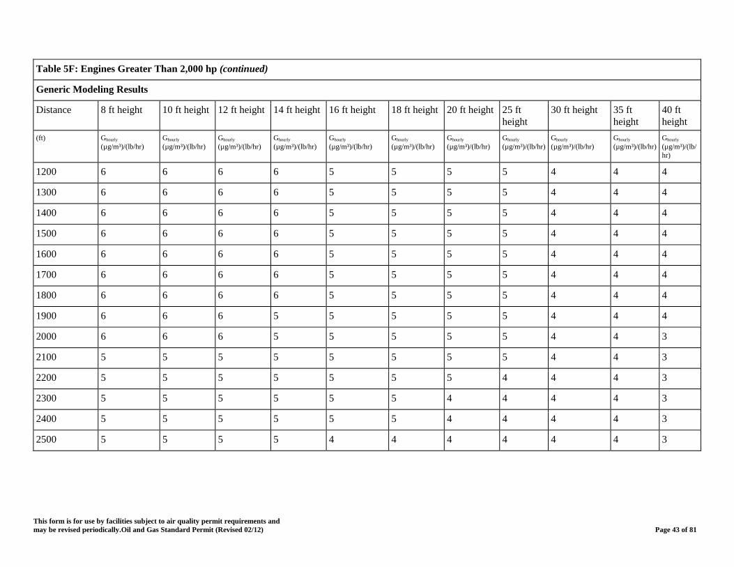
Table 5F: Engines Greater Than 2,000 hp (continued)
Generic Modeling Results
Distance 8 ft height 10 ft height 12 ft height 14 ft height 16 ft height 18 ft height 20 ft height 25 ft height
30 ft height 35 ft height
40 ft height
(ft) Ghourly (µg/m³)/(lb/hr)
Ghourly (µg/m³)/(lb/hr)
Ghourly (µg/m³)/(lb/hr)
Ghourly (µg/m³)/(lb/hr)
Ghourly (µg/m³)/(lb/hr)
Ghourly (µg/m³)/(lb/hr)
Ghourly (µg/m³)/(lb/hr)
Ghourly (µg/m³)/(lb/hr)
Ghourly (µg/m³)/(lb/hr)
Ghourly (µg/m³)/(lb/hr)
Ghourly (µg/m³)/(lb/hr)
1200 6 6 6 6 5 5 5 5 4 4 4
1300 6 6 6 6 5 5 5 5 4 4 4
1400 6 6 6 6 5 5 5 5 4 4 4
1500 6 6 6 6 5 5 5 5 4 4 4
1600 6 6 6 6 5 5 5 5 4 4 4
1700 6 6 6 6 5 5 5 5 4 4 4
1800 6 6 6 6 5 5 5 5 4 4 4
1900 6 6 6 5 5 5 5 5 4 4 4
2000 6 6 6 5 5 5 5 5 4 4 3
2100 5 5 5 5 5 5 5 5 4 4 3
2200 5 5 5 5 5 5 5 4 4 4 3
2300 5 5 5 5 5 5 4 4 4 4 3
2400 5 5 5 5 5 5 4 4 4 4 3
2500 5 5 5 5 4 4 4 4 4 4 3
This form is for use by facilities subject to air quality permit requirements and may be revised periodically.Oil and Gas Standard Permit (Revised 02/12) Page 43 of 81
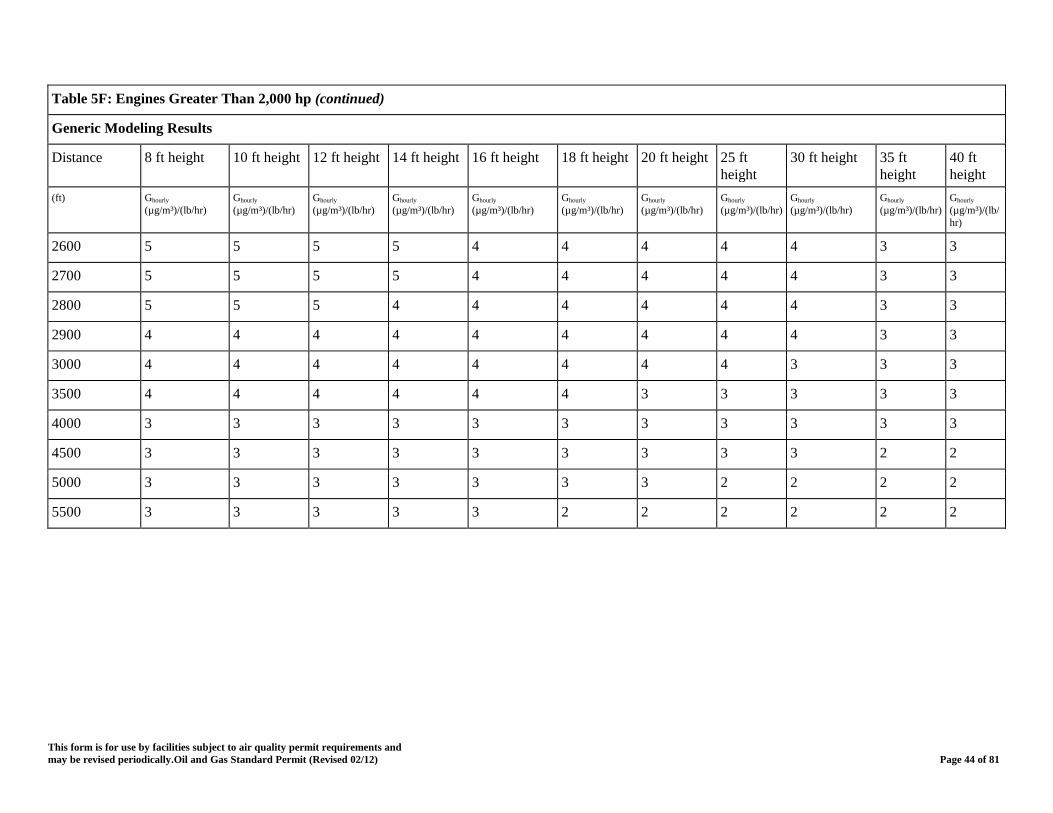
Table 5F: Engines Greater Than 2,000 hp (continued)
Generic Modeling Results
Distance 8 ft height 10 ft height 12 ft height 14 ft height 16 ft height 18 ft height 20 ft height 25 ft height
30 ft height 35 ft height
40 ft height
(ft) Ghourly (µg/m³)/(lb/hr)
Ghourly (µg/m³)/(lb/hr)
Ghourly (µg/m³)/(lb/hr)
Ghourly (µg/m³)/(lb/hr)
Ghourly (µg/m³)/(lb/hr)
Ghourly (µg/m³)/(lb/hr)
Ghourly (µg/m³)/(lb/hr)
Ghourly (µg/m³)/(lb/hr)
Ghourly (µg/m³)/(lb/hr)
Ghourly (µg/m³)/(lb/hr)
Ghourly (µg/m³)/(lb/hr)
2600 5 5 5 5 4 4 4 4 4 3 3
2700 5 5 5 5 4 4 4 4 4 3 3
2800 5 5 5 4 4 4 4 4 4 3 3
2900 4 4 4 4 4 4 4 4 4 3 3
3000 4 4 4 4 4 4 4 4 3 3 3
3500 4 4 4 4 4 4 3 3 3 3 3
4000 3 3 3 3 3 3 3 3 3 3 3
4500 3 3 3 3 3 3 3 3 3 2 2
5000 3 3 3 3 3 3 3 2 2 2 2
5500 3 3 3 3 3 2 2 2 2 2 2
This form is for use by facilities subject to air quality permit requirements and may be revised periodically.Oil and Gas Standard Permit (Revised 02/12) Page 44 of 81
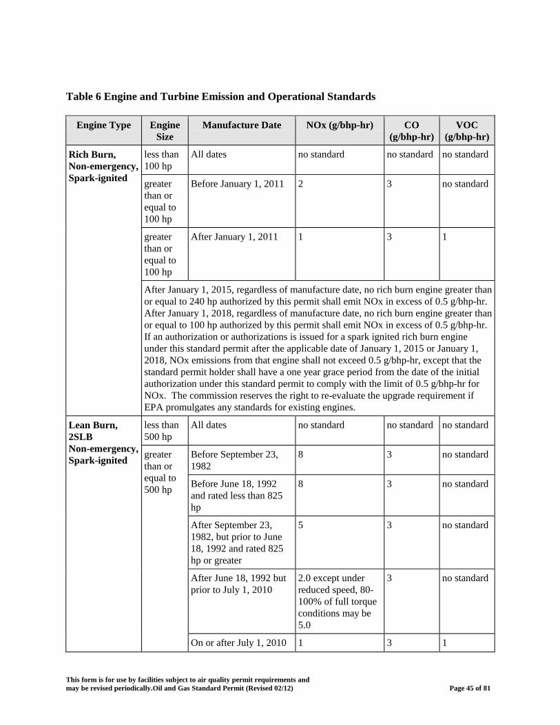
Table 6 Engine and Turbine Emission and Operational Standards
Engine Type Engine Size
Manufacture Date NOx (g/bhp-hr) CO (g/bhp-hr)
VOC (g/bhp-hr)
Rich Burn, Non-emergency, Spark-ignited
less than 100 hp
All dates no standard no standard no standard
greater than or equal to 100 hp
Before January 1, 2011 2 3 no standard
greater than or equal to 100 hp
After January 1, 2011 1 3 1
After January 1, 2015, regardless of manufacture date, no rich burn engine greater than or equal to 240 hp authorized by this permit shall emit NOx in excess of 0.5 g/bhp-hr. After January 1, 2018, regardless of manufacture date, no rich burn engine greater than or equal to 100 hp authorized by this permit shall emit NOx in excess of 0.5 g/bhp-hr. If an authorization or authorizations is issued for a spark ignited rich burn engine under this standard permit after the applicable date of January 1, 2015 or January 1, 2018, NOx emissions from that engine shall not exceed 0.5 g/bhp-hr, except that the standard permit holder shall have a one year grace period from the date of the initial authorization under this standard permit to comply with the limit of 0.5 g/bhp-hr for NOx. The commission reserves the right to re-evaluate the upgrade requirement if EPA promulgates any standards for existing engines.
Lean Burn, 2SLB Non-emergency, Spark-ignited
less than 500 hp
All dates no standard no standard no standard
greater than or equal to 500 hp
Before September 23, 1982
8 3 no standard
Before June 18, 1992 and rated less than 825 hp
8 3 no standard
After September 23, 1982, but prior to June 18, 1992 and rated 825 hp or greater
5 3 no standard
After June 18, 1992 but prior to July 1, 2010
2.0 except under reduced speed, 80-100% of full torque conditions may be 5.0
3 no standard
On or after July 1, 2010 1 3 1
This form is for use by facilities subject to air quality permit requirements and may be revised periodically.Oil and Gas Standard Permit (Revised 02/12) Page 45 of 81
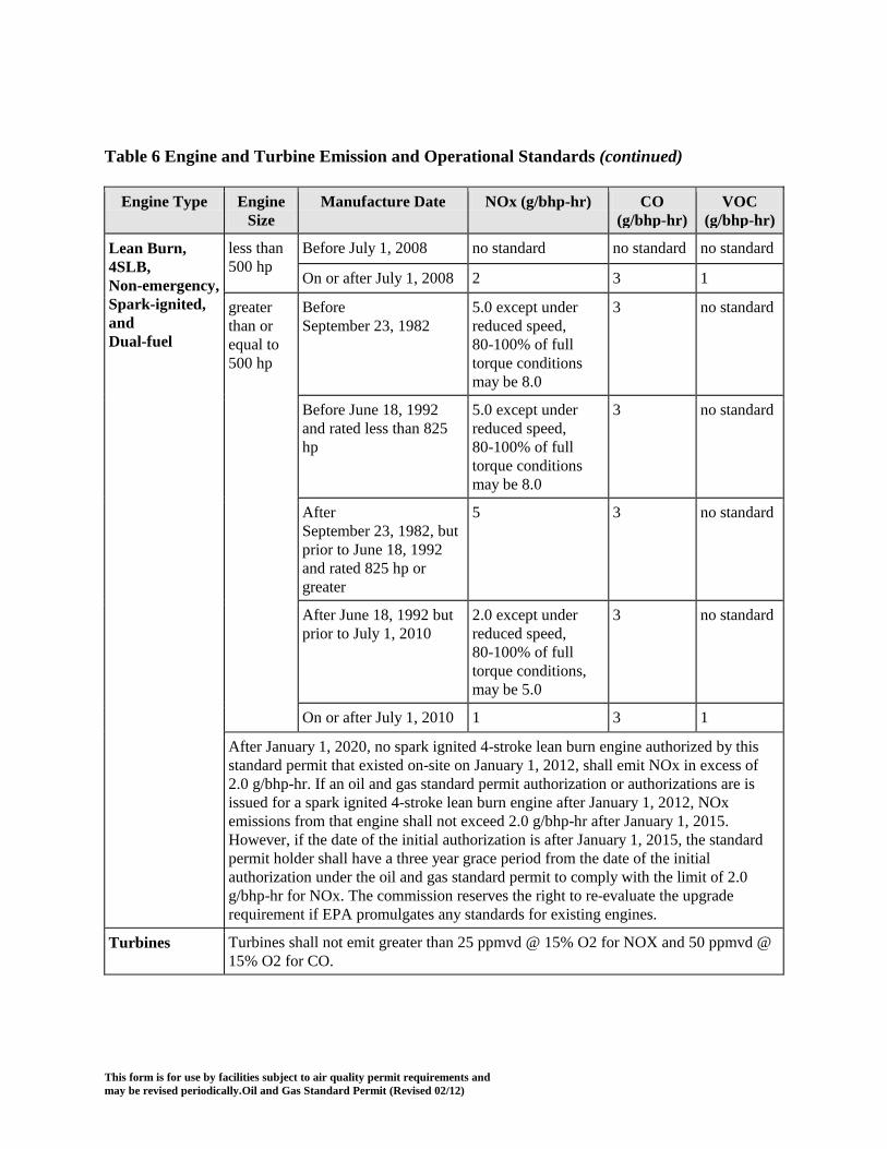
Table 6 Engine and Turbine Emission and Operational Standards (continued)
Engine Type Engine Size
Manufacture Date NOx (g/bhp-hr) CO (g/bhp-hr)
VOC (g/bhp-hr)
Lean Burn, 4SLB, Non-emergency, Spark-ignited, and Dual-fuel
less than 500 hp
Before July 1, 2008 no standard no standard no standard
On or after July 1, 2008 2 3 1
greater than or equal to 500 hp
Before September 23, 1982
5.0 except under reduced speed, 80-100% of full torque conditions may be 8.0
3 no standard
Before June 18, 1992 and rated less than 825 hp
5.0 except under reduced speed, 80-100% of full torque conditions may be 8.0
3 no standard
After September 23, 1982, but prior to June 18, 1992 and rated 825 hp or greater
5 3 no standard
After June 18, 1992 but prior to July 1, 2010
2.0 except under reduced speed, 80-100% of full torque conditions, may be 5.0
3 no standard
On or after July 1, 2010 1 3 1
After January 1, 2020, no spark ignited 4-stroke lean burn engine authorized by this standard permit that existed on-site on January 1, 2012, shall emit NOx in excess of 2.0 g/bhp-hr. If an oil and gas standard permit authorization or authorizations are is issued for a spark ignited 4-stroke lean burn engine after January 1, 2012, NOx emissions from that engine shall not exceed 2.0 g/bhp-hr after January 1, 2015. However, if the date of the initial authorization is after January 1, 2015, the standard permit holder shall have a three year grace period from the date of the initial authorization under the oil and gas standard permit to comply with the limit of 2.0 g/bhp-hr for NOx. The commission reserves the right to re-evaluate the upgrade requirement if EPA promulgates any standards for existing engines.
Turbines Turbines shall not emit greater than 25 ppmvd @ 15% O2 for NOX and 50 ppmvd @ 15% O2 for CO.
This form is for use by facilities subject to air quality permit requirements and may be revised periodically.Oil and Gas Standard Permit (Revised 02/12)

Table 7 Sampling and Demonstrations of Compliance
Category Description Specifications and Expectations
Exclusions Control Systems
Control device monitoring and records are required only where the device is necessary for the site to meet emission rate limits
Sampling When (A)If necessary, sampling ports and platforms shall be incorporated General Applicable
Ports and Platforms, Methods, Notifications and Timing
into the design of all exhaust stacks according to the specifications set forth in "Chapter 2, Stack Sampling Facilities." Engines and other facilities which are physically incapable of having platforms are excluded from this requirement. For control devices with effectiveness requirements only, appropriate sampling ports shall also be installed upstream of the inlet to control devices or controlled recovery systems with control efficiency requirements. Alternate sampling facility designs may be submitted for written approval by the Texas Commission on Environmental Quality (TCEQ) Regional Director or his designee. (B) Where stack testing is required, Sampling shall be conducted within 180 days of the change that required the registration, in accordance with the appropriate procedures of the TCEQ Sampling Procedures Manual and in accordance with the appropriate EPA Reference Methods. Unless otherwise specified, each performance test shall consist of three separate runs using the applicable test method. Each run shall be conducted for the time and under the conditions specified in the applicable standard. Where appropriate, sampling shall occur as three one-hour test runs and then averaged to demonstrate compliance with the limits of this authorization. Any deviations from those procedures must be approved in writing by the TCEQ Regional Director or his designee prior to sampling. (C) The Regional Office shall be afforded the opportunity to observe all such sampling. (D) The holder of this authorization is responsible for providing sampling and testing facilities and conducting the sampling and testing operations at his expense.
This form is for use by facilities subject to air quality permit requirements and may be revised periodically.Oil and Gas Standard Permit (Revised 02/12)

Table 7 Sampling and Demonstrations of Compliance (continued)
Category Description Specifications and Expectations
Sampling When (E) The TCEQ Regional Office that has jurisdiction over the site General Applicable
Ports and Platforms, Methods, Notifications and Timing
shall be contacted as soon as any testing is scheduled, but not less than 30 days prior to sampling. The region shall have discretion to amend the 30 day prior notification. Except for engine testing and liquid/gas analysis sampling, all other sampling shall include an opportunity for the appropriate regional office to schedule a pretest meeting. The notice shall include: (i) Date for pretest meeting, if required; (ii)Date sampling will occur; (iii) Name of firm conducting sampling; (iv)Type of sampling equipment to be used; (v) Method or procedure to be used in sampling; (vi)Procedure used to determine operating rates or other relevant parameters during the sampling period; (vii) parameters to be documented during the sampling event; (viii) any proposed deviations to the prescribed sampling methods. If held, the purpose of the pretest meeting is to review the necessary sampling and testing procedures, to provide the proper data forms for recording pertinent data, and to review the format procedures for submitting the test reports. (F) Within 60 days after the completion of the testing and sampling required herein, one original and one copy of the sampling reports shall be sent to the Regional Office. (G) When sampling is required, all Quality Assurance/Quality Control shall follow 30 TAC Ch 25 National Environmental Laboratory Accreditation Conference accreditation requirements.
This form is for use by facilities subject to air quality permit requirements and may be revised periodically.Oil and Gas Standard Permit (Revised 02/12)

This form is for use by facilities subject to air quality permit requirements and may be revised periodically.Oil and Gas Standard Permit (Revised 02/12)
Table 7 Sampling and Demonstrations of Compliance (continued)
Category Description Specifications and Expectations
Fugitive monitoring and LDAR
Analyzers An approved gas analyzer or other approved detection monitoring device used for the volatile organic compound fugitive inspection and repair requirement is a device that conforms to the requirements listed in Title 40 CFR §60.485(a) and (b), or is otherwise approved by the Environmental Protection Agency as a device to monitor for VOC fugitive emission leaks. Approved gas analyzers shall conform to requirements listed in Method 21 of 40 CFR Part 60, Appendix A. The gas analyzer shall be calibrated with methane. In addition, the response factor of the instrument for a specific VOC of interest shall be determined and meet the requirements of Standard permit 8 of Method 21. If a mixture of VOCs is being monitored, the response factor shall be calculated for the average composition of the process fluid. If a response factor less than 10 cannot be achieved using methane, then the instrument may be calibrated with one of the VOC to be measured or any other VOC so long as the instrument has a response factor of less than 10 for each of the VOC to be measured. In lieu of using a hydrocarbon gas analyzer and EPA Method 21, the owner or operator may use the Alternative Work Practice in 40 CFR Part 60, §60.18(g) - (i). The optical gas imaging instrument must meet all requirements specified in 40 CFR §60.18(g) - (i), except the annual Test Method 21 requirement in 40 CFR §60.18(h)(7) and the reporting requirement in 40 CFR §60.18(i)(5) do not apply.
Verify composition of materials
All site-specific gas or liquid analyses
Reports necessary to verify composition (including hydrogen sulfide (H2S) at any point in the process. All analyses shall be site specific or a representative sample may be used to estimate emissions if all of the parameters in the gas and liquid analysis protocol provided by the commission are met. A site-specific or define representative analysis shall be performed within 90 days of initial start of operation or implementation of a change which requires registration. When new streams are added to the site and the character or composition of the streams change and cause an increase in authorized emissions, or upon request of the appropriate Regional office or local air pollution control program with jurisdiction, a new analysis will need to be performed. Analysis techniques may include, but are not limited to, Gas Chromatography (GC), Tutweiler, stain tube analysis, and sales oil/condensate reports. These records will document the following: (A) H2S content; (B) flow rate; (C) heat content; or (D) other characteristic including, but not limited to: (i) American Petroleum Institute gravity and Reid vapor pressure (RVP);(ii) sales oil throughput; or (iii) condensate throughput.

This form is for use by facilities subject to air quality permit requirements and may be revised periodically.Oil and Gas Standard Permit (Revised 02/12)
Table 7 Sampling and Demonstrations of Compliance (continued)
Category Description Specifications and Expectations
Verify composition of materials (continued
All site-specific gas or liquid analyses
Laboratory extended VOC GC analysis at a minimum to C10+ and H2S analysis for gas and liquids for the following shall be performed and used for emission compliance demonstrations:(A) Separator at the inlet; (B) Dehydration Unit / Glycol Contactor prior to dehydrator;(C) Amine Unit prior to sweetening unit; (D) Separator dumping to gunbarrel or storage tank; (E) Tanks for liquids and vapors; or (F) P
Engines and Turbines
Initial Sampling of (i)Any engine greater than 500 horsepower; (ii) Any turbine
Perform stack sampling and other testing as required to establish the actual quantities of air contaminants being emitted into the atmosphere (including but not limited to nitrogen oxide (NOX), carbon monoxide (CO), and oxygen (O2). Each combustion facility shall be tested at a minimum of 50% of the design maximum firing rate of the facility. Each tested firing rate shall be identified in the sampling report. Sampling shall occur within 180 days after initial start-up of each unit. Additional sampling shall occur as requested by the TCEQ Regional Director. If there are multiple engines at an oil and gas sites (OGS) of identical model, year, and control system, sampling may be performed on 50% of the units and used for compliance demonstration of all identical units at the OGS. The remaining 50% of the units not initially tested must be tested during the next biennial testing period. This sampling is not required upon initial installation at any location if the engine or turbine was previously installed and tested at any location in the United States and the test conformed with EPA Reference Methods. Regardless of engine location, records of performance testing, or relied upon sampling reports, must remain with each specific engine for a minimum of five years unless records are unavailable and the permit holder performs the initial sampling on-site. No one may claim records are unavailable for the time period in which an engine is at the site which is authorized by this standard permit. This testing is not required for emergency engines unless requested by the TCEQ Regional Director. Idle engines do not need to be re-started only for the purpose of completing required testing. If biennial testing is required for an engine that is re-started for production purposes, the biennial testing is required within 30 days after re-starting the engine.
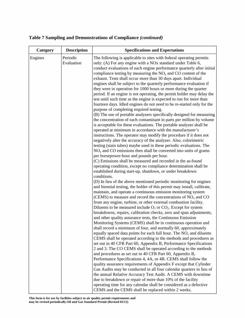
This form is for use by facilities subject to air quality permit requirements and may be revised periodically.Oil and Gas Standard Permit (Revised 02/12)
Table 7 Sampling and Demonstrations of Compliance (continued)
Category Description Specifications and Expectations
Engines Periodic Evaluation
The following is applicable to sites with federal operating permits only: (A) For any engine with a NOx standard under Table 6, conduct evaluations of each engine performance quarterly after initial compliance testing by measuring the NOx and CO content of the exhaust. Tests shall occur more than 30 days apart. Individual engines shall be subject to the quarterly performance evaluation if they were in operation for 1000 hours or more during the quarter period. If an engine is not operating, the permit holder may delay the test until such time as the engine is expected to run for more than fourteen days. Idled engines do not need to be re-started only for the purpose of completing required testing. (B) The use of portable analyzers specifically designed for measuring the concentration of each contaminant in parts per million by volume is acceptable for these evaluations. The portable analyzer shall be operated at minimum in accordance with the manufacturer’s instructions. The operator may modify the procedure if it does not negatively alter the accuracy of the analyzer. Also, colorimetric testing (stain tubes) maybe used in these periodic evaluations. The NOx and CO emissions then shall be converted into units of grams per horsepower-hour and pounds per hour. (C) Emissions shall be measured and recorded in the as-found operating condition, except no compliance determination shall be established during start-up, shutdown, or under breakdown conditions. (D) In lieu of the above mentioned periodic monitoring for engines and biennial testing, the holder of this permit may install, calibrate, maintain, and operate a continuous emission monitoring system (CEMS) to measure and record the concentrations of NOx and CO from any engine, turbine, or other external combustion facility. Diluents to be measured include O2 or CO2. Except for system breakdowns, repairs, calibration checks, zero and span adjustments, and other quality assurance tests, the Continuous Emission Monitoring Systems (CEMS) shall be in continuous operation and shall record a minimum of four, and normally 60, approximately equally spaced data points for each full hour. The NOx and diluents CEMS shall be operated according to the methods and procedures as set out in 40 CFR Part 60, Appendix B, Performance Specifications 2 and 3. The CO CEMS shall be operated according to the methods and procedures as set out in 40 CFR Part 60, Appendix B, Performance Specifications 4, 4A, or 4B. CEMS shall follow the quality assurance requirements of Appendix F except that Cylinder Gas Audits may be conducted in all four calendar quarters in lieu of the annual Relative Accuracy Test Audit. A CEMS with downtime due to breakdown or repair of more than 10% of the facility operating time for any calendar shall be considered as a defective CEMS and the CEMS shall be replaced within 2 weeks.

This form is for use by facilities subject to air quality permit requirements and may be revised periodically.Oil and Gas Standard Permit (Revised 02/12)
Table 7 Sampling and Demonstrations of Compliance (continued)
Category Description Specifications and Expectations
Engines and Turbines
Biennial Testing Any engine greater than 500 horsepower or any turbine
Every two years starting from the completion date of the Initial Compliance Testing, any engine greater than 500 horsepower or any turbine shall be retested according to the procedures of the Initial Compliance Testing. Retesting shall occur within 90 days of the two year anniversary date. If a facility has been operated for less than 2000 hours during the two year period, it may skip the retesting requirement for that period. After biennial testing, any engine retested under the above requirements shall resume periodic evaluations within the next 6 calendar months (January to June or July to December). If biennial testing is required for an engine that is re-started for production purposes, the biennial testing shall be performed within 45 days after re-starting the engine.
Oxidation or Combustion Control Device
Initial Sampling and Monitoring for performance for VOC, Benzene, and H2S
Stack testing, when a company wants to establish efficiencies of 99% or greater, must be coordinated and approved. Sampling is required for VOC, benzene and H2S at Region's discretion. The thermal oxidizer (TO) must have proper monitoring and sampling ports installed in the vent stream and the exit to the combustion chamber, to monitor and test the unit simultaneously. The temperature and oxygen measurement devices shall reduce the temperature and oxygen concentration readings to an averaging period of 6 minutes or less and record it at that frequency. The temperature measurement device shall be installed, calibrated, and maintained according to accepted practice and the manufacturer's specifications. The device shall have an accuracy of the greater of ±0.75% of the temperature being measured expressed in degrees Celsius or ±2.5ºC. The oxygen or carbon monoxide analyzer shall be zeroed and spanned daily and corrective action taken when the 24-hour span drift exceeds two times the amounts specified Performance Specification No. 3 or 4A, 40 CFR Part 60, Appendix B. Zero and span is not required on weekends and plant holidays if instrument technicians are not normally scheduled on those days.

This form is for use by facilities subject to air quality permit requirements and may be revised periodically.Oil and Gas Standard Permit (Revised 02/12)
Table 7 Sampling and Demonstrations of Compliance (continued)
Category Description Specifications and Expectations
Oxidation or Combustion Control Device
Initial Sampling and Monitoring for performance for VOC, Benzene, and H2S
The oxygen or carbon monoxide analyzer shall be quality-assured at least semiannually using cylinder gas audits (CGAs) in accordance with 40 CFR Part 60, Appendix F, Procedure 1, §5.1.2, with the following exception: a relative accuracy test audit is not required once every four quarters (i.e., two successive semiannual CGAs may be conducted). An equivalent quality-assurance method approved by the TCEQ may also be used. Successive semiannual audits shall occur no closer than four months. Necessary corrective action shall be taken for all CGA exceedances of ±15 percent accuracy and any continuous emissions monitoring system downtime in excess of 5% of the incinerator operating time. These occurrences and corrective actions shall be reported to the appropriate TCEQ Regional Director on a quarterly basis. Supplemental stack concentration measurements may be required at the discretion of the appropriate TCEQ Regional Director. Quality assured or valid data of oxygen or carbon monoxide analyzer must be generated when the TO is operating except during the performance of a daily zero and span check. Loss of valid data due to periods of monitor break down, inaccurate data, repair, maintenance, or calibration may be exempted provided it does not exceed 5% of the time (in minutes) that the oxidizer operated over the previous rolling 12 month period. The measurements missed shall be estimated using engineering judgment and the methods used recorded.
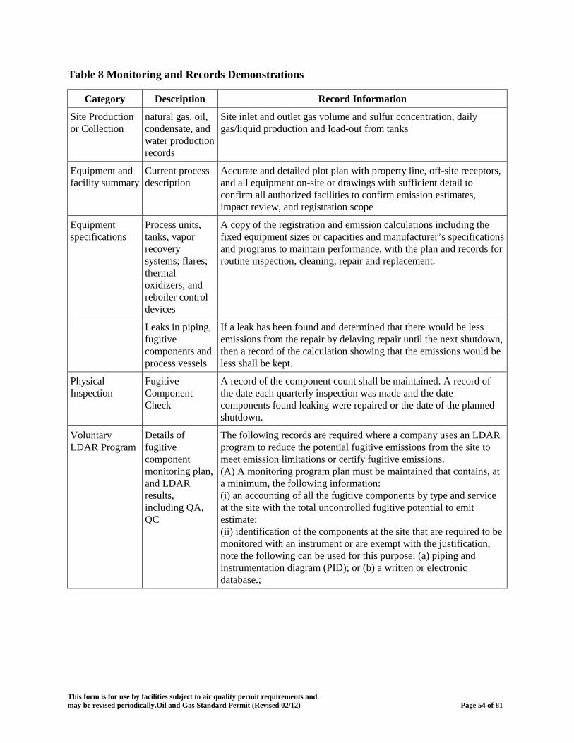
This form is for use by facilities subject to air quality permit requirements and may be revised periodically.Oil and Gas Standard Permit (Revised 02/12) Page 54 of 81
Table 8 Monitoring and Records Demonstrations
Category Description Record Information
Site Production or Collection
natural gas, oil, condensate, and water production records
Site inlet and outlet gas volume and sulfur concentration, daily gas/liquid production and load-out from tanks
Equipment and facility summary
Current process description
Accurate and detailed plot plan with property line, off-site receptors, and all equipment on-site or drawings with sufficient detail to confirm all authorized facilities to confirm emission estimates, impact review, and registration scope
Equipment specifications
Process units, tanks, vapor recovery systems; flares; thermal oxidizers; and reboiler control devices
A copy of the registration and emission calculations including the fixed equipment sizes or capacities and manufacturer’s specifications and programs to maintain performance, with the plan and records for routine inspection, cleaning, repair and replacement.
Leaks in piping, fugitive components and process vessels
If a leak has been found and determined that there would be less emissions from the repair by delaying repair until the next shutdown, then a record of the calculation showing that the emissions would be less shall be kept.
Physical Inspection
Fugitive Component Check
A record of the component count shall be maintained. A record of the date each quarterly inspection was made and the date components found leaking were repaired or the date of the planned shutdown.
Voluntary LDAR Program
Details of fugitive component monitoring plan, and LDAR results, including QA, QC
The following records are required where a company uses an LDAR program to reduce the potential fugitive emissions from the site to meet emission limitations or certify fugitive emissions. (A) A monitoring program plan must be maintained that contains, at a minimum, the following information: (i) an accounting of all the fugitive components by type and service at the site with the total uncontrolled fugitive potential to emit estimate; (ii) identification of the components at the site that are required to be monitored with an instrument or are exempt with the justification, note the following can be used for this purpose: (a) piping and instrumentation diagram (PID); or (b) a written or electronic database.;
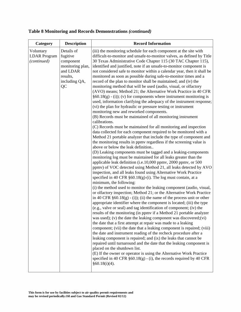
This form is for use by facilities subject to air quality permit requirements and may be revised periodically.Oil and Gas Standard Permit (Revised 02/12)
Table 8 Monitoring and Records Demonstrations (continued)
Category Description Record Information
Voluntary LDAR Program (continued)
Details of fugitive component monitoring plan, and LDAR results, including QA, QC
(iii) the monitoring schedule for each component at the site with difficult-to-monitor and unsafe-to-monitor valves, as defined by Title 30 Texas Administrative Code Chapter 115 (30 TAC Chapter 115), identified and justified, note if an unsafe-to-monitor component is not considered safe to monitor within a calendar year, then it shall be monitored as soon as possible during safe-to-monitor times and a record of the plan to monitor shall be maintained; and (iv) the monitoring method that will be used (audio, visual, or olfactory (AVO) means; Method 21; the Alternative Work Practice in 40 CFR §60.18(g) - (i)); (v) for components where instrument monitoring is used, information clarifying the adequacy of the instrument response; (vi) the plan for hydraulic or pressure testing or instrument monitoring new and reworked components. (B) Records must be maintained of all monitoring instrument calibrations. (C) Records must be maintained for all monitoring and inspection data collected for each component required to be monitored with a Method 21 portable analyzer that include the type of component and the monitoring results in ppmv regardless if the screening value is above or below the leak definition.. (D) Leaking components must be tagged and a leaking-components monitoring log must be maintained for all leaks greater than the applicable leak definition (i.e.10,000 ppmv, 2000 ppmv, or 500 ppmv) of VOC detected using Method 21, all leaks detected by AVO inspection, and all leaks found using Alternative Work Practice specified in 40 CFR §60.18(g)-(i). The log must contain, at a minimum, the following: (i) the method used to monitor the leaking component (audio, visual, or olfactory inspection; Method 21; or the Alternative Work Practice in 40 CFR §60.18(g) - (i)); (ii) the name of the process unit or other appropriate identifier where the component is located; (iii) the type (e.g., valve or seal) and tag identification of component; (iv) the results of the monitoring (in ppmv if a Method 21 portable analyzer was used); (v) the date the leaking component was discovered;(vi) the date that a first attempt at repair was made to a leaking component; (vii) the date that a leaking component is repaired; (viii) the date and instrument reading of the recheck procedure after a leaking component is repaired; and (ix) the leaks that cannot be repaired until turnaround and the date that the leaking component is placed on the shutdown list. (E) If the owner or operator is using the Alternative Work Practice specified in 40 CFR §60.18(g) - (i), the records required by 40 CFR §60.18(i)(4).

This form is for use by facilities subject to air quality permit requirements and may be revised periodically.Oil and Gas Standard Permit (Revised 02/12)
Table 8 Monitoring and Records Demonstrations (continued)
Category Description Record Information
Voluntary LDAR Program (continued)
Details of fugitive component monitoring plan, and LDAR results, including QA, QC
(F) A record of the monitored value any open-ended line or valve for which is a repair or replacement is not completed within 72 hours and monitoring in lieu of covering is chosen. (G) Any open-ended line or valve caused by a repair or replacement not completed within 72 hours shall be monitored as specified in table 10 and the checks and any corrective actions taken shall be recorded. (H) Weekly audio, visual and olfactory inspections shall be noted in a log (I) A check of the reading for any pressure-sensing device to verify rupture disc integrity shall be performed weekly and noted in a log.
Minor Changes Additions, changes or replacement
Records showing all replacements and additions, including summary of emission type and quantities, for a rolling 6-month period of time.
Equipment Replacement
Like-Kind replacement
Records on equipment specifications and operations, including summary of emissions type and quantity.
Process Units Glycol Dehydration Units
For emission estimates, the worst-case combination of parameters resulting in the greatest emission rates must be used. If worst-case parameters are not used, then glycol dehydrator unit monitoring records include dry gas flow rate, absorber pressure and temperature, glycol type, and circulation rate recorded weekly. If worst-case parameters are not used, then in addition to weekly unit monitoring, where control of flash tank or reboiler emissions are required to meet the emission limitations of the section and emissions are certified, the following control monitoring requirements apply weekly: flash tank temperature and pressure, any reboiler stripping gas flow rate, and condenser outlet temperature. VRU, flare, or thermal oxidizer control or reboiler fire box used for control must comply with the monitoring and recordkeeping for those devices. Where all emissions from the flash tank and the reboiler or reboiler condenser vent are directed to a VRU, flare, or thermal oxidizer designed to be on-line at all times the glycol dehydrator is in operation, the control system monitoring for the glycol dehydrator is not required.
Amine Units Amine units may simply retain site production or inlet gas records if all sulfur compounds in the inlet are assumed to be emitted. Where only partial removal of the inlet sulfur is assumed, for emission estimates, the worst-case combination of parameters resulting in the greatest emission rates must be used. If worst-case parameters are not used, then records of the amine solution, contactor pressure, temperature and pump rate shall be maintained. Where the waste gas is vented to combustion control, the requirements of the control device utilized should be noted.

This form is for use by facilities subject to air quality permit requirements and may be revised periodically.Oil and Gas Standard Permit (Revised 02/12)
Table 8 Monitoring and Records Demonstrations (continued)
Category Description Record Information
Boilers, Reboilers, Heater-Treaters, and and Process Heaters
Combustion Records of Operational Monitoring and Testing Records Records of the hours of operation of every combustion device of any size by the use of a process monitor such as a run time meter, fuel flow meter, or other process variable that indicates a unit is running unless, in the registration for the facility, the emissions from the facility were calculated using full year operation at maximum design capacity in which case no hours of operation records must be kept.
Internal Combustion Engines
Combustion
Records of Appropriate Operational Monitoring and Testing Records Records of the hours of operation of every combustion device and engine of any size by the use of a process monitor such as a run time meter, fuel flow meter, or other process variable that indicates a unit is running. The owner or operator may test and retest at the most frequent intervals identified in Table 7 in lieu of installing a process monitor and recording the hours of operation. If an engine has no testing requirements in Table 7, no records of the hours of operation must be kept. See fuel records below
Gas Fired Turbines
Combustion Records of Appropriate Operational Monitoring and Testing Records Records of the hours of operation of every turbine greater than 500 hp by the use of a process monitor such as a run time meter, fuel flow meter, or other process variable that indicates a unit is running unless the permit holder determined emissions from the facility assuming full year operation at maximum design capacity in which case no hours of operation records must be kept.
Fuel Records VOC and Sulfur Content
A fuel flow meter is not required if emissions are based on maximum fuel usage for 8,760 hr/yr. There are no specific requirements for allowable VOC content of fuel. If field gas contains more than 1.5 grains (24 ppmv) of H2S or 30 grains total sulfur compounds per 100 dry standard cubic feet, the operator shall maintain records, including at least quarterly measurements of fuel H2S and total sulfur content, which demonstrate that the annual SO2 emissions do not exceed limitations
Tanks/Vessels Color/Exterior Records demonstrating design, inspection, and maintenance of paint color and vessel integrity.
Tanks/Vessels Emission and emission potential
Maintain a record of the material stored in each tank/vessel that vents to the atmosphere and the maximum vapor pressure used to establish the maximum potential short-term emission rate. Where pressurized liquids can flash in the tank/vessel monitor and record weekly the maximum fluid pressure that can enter the tank / vessel. Records that tank / vessel hatches and relief valves are properly sealed when tank /vessel is directed to control and after loading events (as needed).
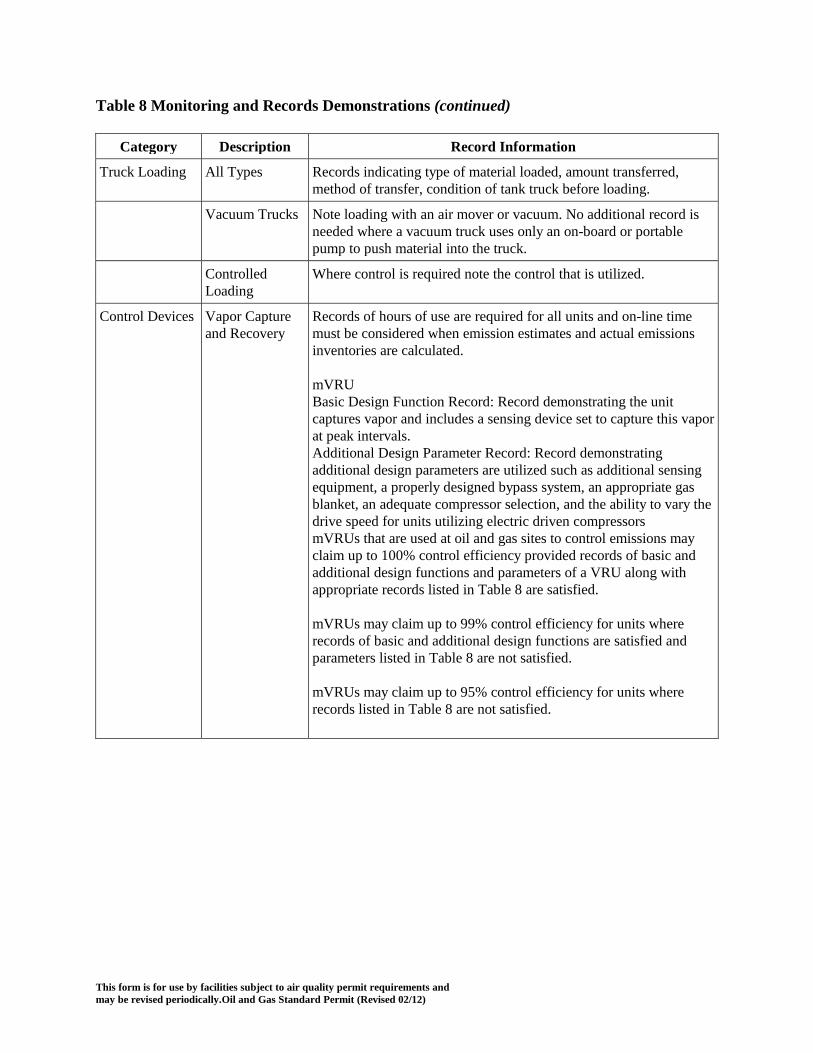
This form is for use by facilities subject to air quality permit requirements and may be revised periodically.Oil and Gas Standard Permit (Revised 02/12)
Table 8 Monitoring and Records Demonstrations (continued)
Category Description Record Information
Truck Loading All Types Records indicating type of material loaded, amount transferred, method of transfer, condition of tank truck before loading.
Vacuum Trucks Note loading with an air mover or vacuum. No additional record is needed where a vacuum truck uses only an on-board or portable pump to push material into the truck.
Controlled Loading
Where control is required note the control that is utilized.
Control Devices Vapor Capture and Recovery
Records of hours of use are required for all units and on-line time must be considered when emission estimates and actual emissions inventories are calculated. mVRU Basic Design Function Record: Record demonstrating the unit captures vapor and includes a sensing device set to capture this vapor at peak intervals. Additional Design Parameter Record: Record demonstrating additional design parameters are utilized such as additional sensing equipment, a properly designed bypass system, an appropriate gas blanket, an adequate compressor selection, and the ability to vary the drive speed for units utilizing electric driven compressors mVRUs that are used at oil and gas sites to control emissions may claim up to 100% control efficiency provided records of basic and additional design functions and parameters of a VRU along with appropriate records listed in Table 8 are satisfied. mVRUs may claim up to 99% control efficiency for units where records of basic and additional design functions are satisfied and parameters listed in Table 8 are not satisfied. mVRUs may claim up to 95% control efficiency for units where records listed in Table 8 are not satisfied.
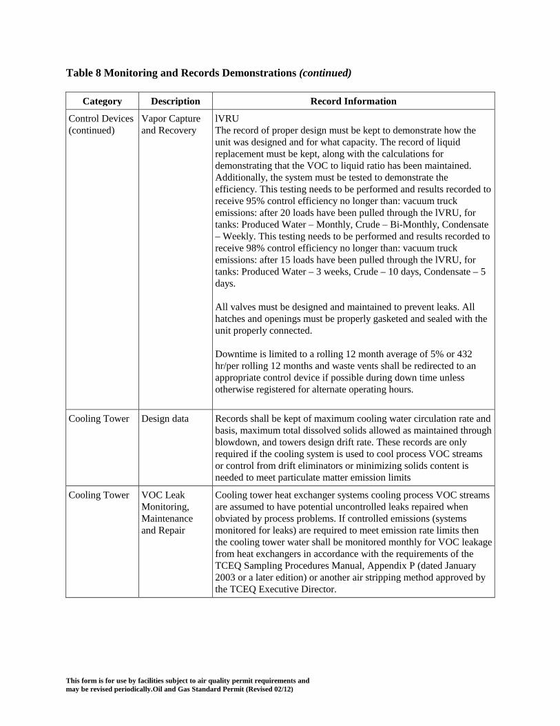
This form is for use by facilities subject to air quality permit requirements and may be revised periodically.Oil and Gas Standard Permit (Revised 02/12)
Table 8 Monitoring and Records Demonstrations (continued)
Category Description Record Information
Control Devices (continued)
Vapor Capture and Recovery
lVRU The record of proper design must be kept to demonstrate how the unit was designed and for what capacity. The record of liquid replacement must be kept, along with the calculations for demonstrating that the VOC to liquid ratio has been maintained. Additionally, the system must be tested to demonstrate the efficiency. This testing needs to be performed and results recorded to receive 95% control efficiency no longer than: vacuum truck emissions: after 20 loads have been pulled through the lVRU, for tanks: Produced Water – Monthly, Crude – Bi-Monthly, Condensate – Weekly. This testing needs to be performed and results recorded to receive 98% control efficiency no longer than: vacuum truck emissions: after 15 loads have been pulled through the lVRU, for tanks: Produced Water – 3 weeks, Crude – 10 days, Condensate – 5 days. All valves must be designed and maintained to prevent leaks. All hatches and openings must be properly gasketed and sealed with the unit properly connected. Downtime is limited to a rolling 12 month average of 5% or 432 hr/per rolling 12 months and waste vents shall be redirected to an appropriate control device if possible during down time unless otherwise registered for alternate operating hours.
Cooling Tower Design data Records shall be kept of maximum cooling water circulation rate and basis, maximum total dissolved solids allowed as maintained through blowdown, and towers design drift rate. These records are only required if the cooling system is used to cool process VOC streams or control from drift eliminators or minimizing solids content is needed to meet particulate matter emission limits
Cooling Tower VOC Leak Monitoring, Maintenance and Repair
Cooling tower heat exchanger systems cooling process VOC streams are assumed to have potential uncontrolled leaks repaired when obviated by process problems. If controlled emissions (systems monitored for leaks) are required to meet emission rate limits then the cooling tower water shall be monitored monthly for VOC leakage from heat exchangers in accordance with the requirements of the TCEQ Sampling Procedures Manual, Appendix P (dated January 2003 or a later edition) or another air stripping method approved by the TCEQ Executive Director.

This form is for use by facilities subject to air quality permit requirements and may be revised periodically.Oil and Gas Standard Permit (Revised 02/12)
Table 8 Monitoring and Records Demonstrations (continued)
Category Description Record Information
Cooling Tower (continued)
VOC Leak Monitoring, Maintenance and Repair
Cooling water VOC concentrations above 0.08 parts per million by volume (ppmv) indicate faulty equipment. Equipment shall be maintained so as to minimize VOC emissions into the cooling water. Faulty equipment shall be repaired at the earliest opportunity but no later than the next scheduled shutdown of the process unit in which the leak occurs. Records must be maintained of all monitoring data and equipment repairs.
Particulate Monitoring, Maintenance and Repair.
Inspect and record integrity of drift eliminators annually, repairing as necessary. If a maximum solids content must be maintained through blowdowns to meet particulate emission rate limits, cooling water shall be sampled for total dissolved solids (TDS) once a month at prior to any periodic blow downs and maintain records of the monitoring results and all corrective actions.
Planned Maintenance, Start-up, and Shutdown (MSS)
Alternate Operational Scenarios and Redirection of Vent Streams
Records of redirection of vent streams during primary operational unit or control downtime, including associated alternate controls, releases and compliance with emission limitations.
Planned MSS Pigging, Purging and Blowdowns
Pigging records, including catcher design, date, emission estimate to atmosphere and to control, and when controlled, the control device. Note where a control device is necessary to meet emission limitations the device is subject to the requirements of standard permit (e) and record requirements of this table. Purging and blowdown records, including the volume and pressure and a description of the piping and equipment involved, the date, emission estimate to atmosphere and to control, and when controlled, the control device. Where purging to control to meet a lower concentration before purging to atmosphere is conducted the concentrations of VOC, BTEX or H2S as appropriate must be measured and recorded prior to purging to atmosphere. Note where a control device is necessary to meet emission limitations the device is subject to the requirements of standard permit (e) and record requirements of this table.
Planned MSS Temporary Facilities for Bypass, and Degassing and Purging
Temporary facility records, including a description and estimate of potential fugitive emissions from temporary piping, size and design of facilities (eg. tanks or pan volume, fill method, and throughput; engine horse power, fuel and usage time, flare tip area, ignition method, and heating value assurance method; etc.) and the date and emission estimate to atmosphere and to control for their use
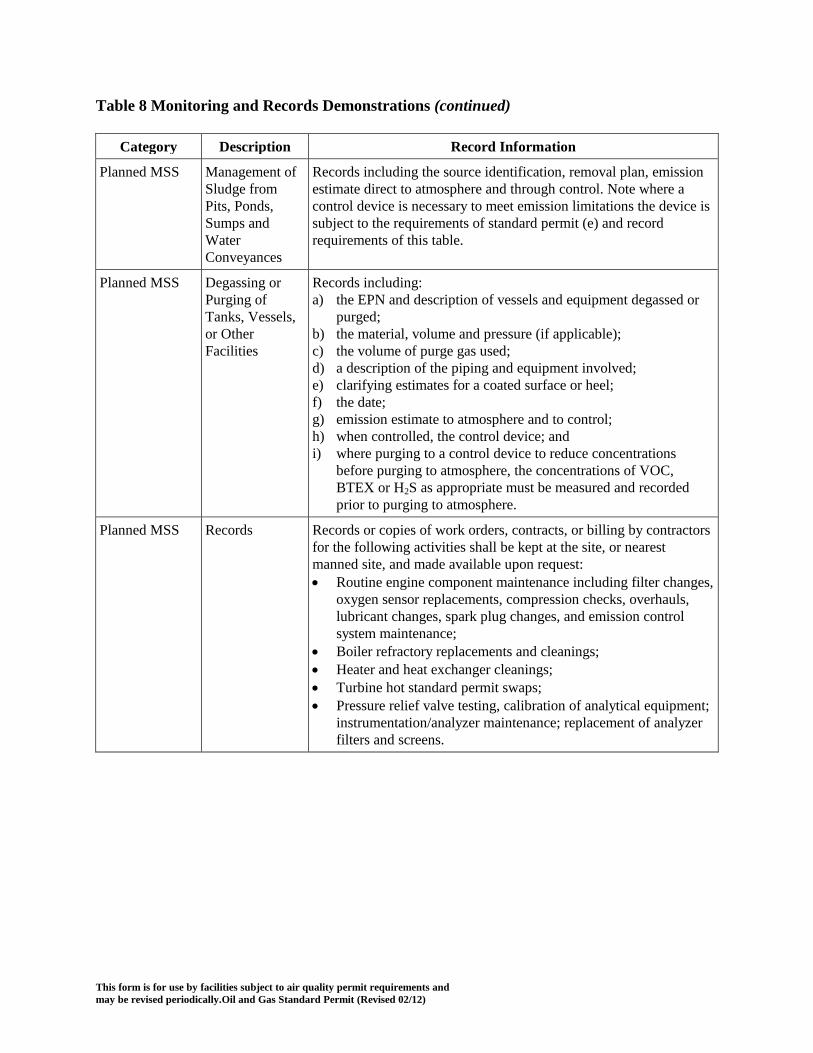
This form is for use by facilities subject to air quality permit requirements and may be revised periodically.Oil and Gas Standard Permit (Revised 02/12)
Table 8 Monitoring and Records Demonstrations (continued)
Category Description Record Information
Planned MSS Management of Sludge from Pits, Ponds, Sumps and Water Conveyances
Records including the source identification, removal plan, emission estimate direct to atmosphere and through control. Note where a control device is necessary to meet emission limitations the device is subject to the requirements of standard permit (e) and record requirements of this table.
Planned MSS Degassing or Purging of Tanks, Vessels, or Other Facilities
Records including: a) the EPN and description of vessels and equipment degassed or
purged; b) the material, volume and pressure (if applicable); c) the volume of purge gas used; d) a description of the piping and equipment involved; e) clarifying estimates for a coated surface or heel; f) the date; g) emission estimate to atmosphere and to control; h) when controlled, the control device; and i) where purging to a control device to reduce concentrations
before purging to atmosphere, the concentrations of VOC, BTEX or H2S as appropriate must be measured and recorded prior to purging to atmosphere.
Planned MSS Records Records or copies of work orders, contracts, or billing by contractors for the following activities shall be kept at the site, or nearest manned site, and made available upon request: • Routine engine component maintenance including filter changes,
oxygen sensor replacements, compression checks, overhauls, lubricant changes, spark plug changes, and emission control system maintenance;
• Boiler refractory replacements and cleanings; • Heater and heat exchanger cleanings; • Turbine hot standard permit swaps; • Pressure relief valve testing, calibration of analytical equipment;
instrumentation/analyzer maintenance; replacement of analyzer filters and screens.
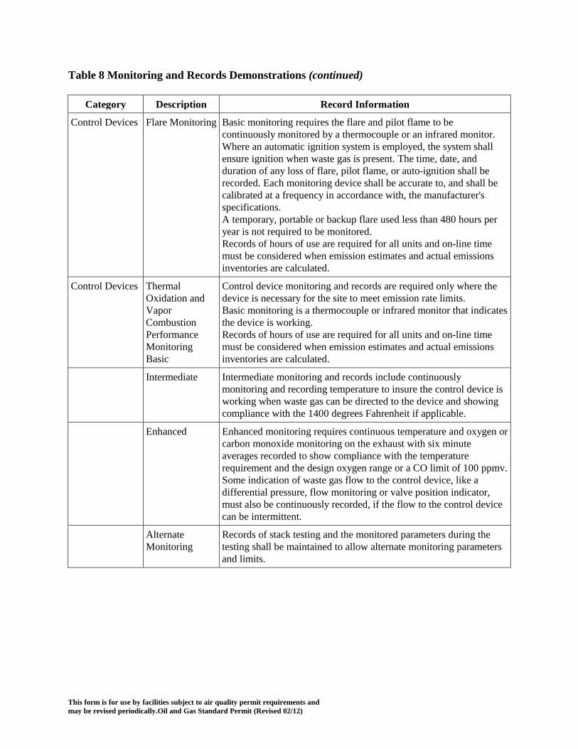
This form is for use by facilities subject to air quality permit requirements and may be revised periodically.Oil and Gas Standard Permit (Revised 02/12)
Table 8 Monitoring and Records Demonstrations (continued)
Category Description Record Information
Control Devices Flare Monitoring Basic monitoring requires the flare and pilot flame to be continuously monitored by a thermocouple or an infrared monitor. Where an automatic ignition system is employed, the system shall ensure ignition when waste gas is present. The time, date, and duration of any loss of flare, pilot flame, or auto-ignition shall be recorded. Each monitoring device shall be accurate to, and shall be calibrated at a frequency in accordance with, the manufacturer's specifications. A temporary, portable or backup flare used less than 480 hours per year is not required to be monitored. Records of hours of use are required for all units and on-line time must be considered when emission estimates and actual emissions inventories are calculated.
Control Devices Thermal Oxidation and Vapor Combustion Performance Monitoring Basic
Control device monitoring and records are required only where the device is necessary for the site to meet emission rate limits. Basic monitoring is a thermocouple or infrared monitor that indicates the device is working. Records of hours of use are required for all units and on-line time must be considered when emission estimates and actual emissions inventories are calculated.
Intermediate Intermediate monitoring and records include continuously monitoring and recording temperature to insure the control device is working when waste gas can be directed to the device and showing compliance with the 1400 degrees Fahrenheit if applicable.
Enhanced Enhanced monitoring requires continuous temperature and oxygen or carbon monoxide monitoring on the exhaust with six minute averages recorded to show compliance with the temperature requirement and the design oxygen range or a CO limit of 100 ppmv. Some indication of waste gas flow to the control device, like a differential pressure, flow monitoring or valve position indicator, must also be continuously recorded, if the flow to the control device can be intermittent.
Alternate Monitoring
Records of stack testing and the monitored parameters during the testing shall be maintained to allow alternate monitoring parameters and limits.

This form is for use by facilities subject to air quality permit requirements and may be revised periodically.Oil and Gas Standard Permit (Revised 02/12)
Table 8 Monitoring and Records Demonstrations (continued)
Category Description Record Information
Control Devices Control with process combustion or heating devices (e.g. reboilers, heaters and furnaces)
Basic monitoring is any continuous monitor that indicates when the flame in the device is on or off (other than partial operational use). The following are effective basic options: a fire box temperature monitor, rising or steady process temperature monitor, CO monitor, primary fuel flow monitor, fire box pressure monitor or equivalent. Enhanced monitoring for 91 to 99% control, where waste gas is not introduced as the primary fuel, must include the following monitors: continuous fire box or fire box exhaust temperature, and CO and O2 monitoring, with at least 6 minute averages recorded. Additionally, enhanced monitoring where the waste gas may be flowing when the control device is not firing must show continuous disposition of the waste gas streams, including continuous monitoring of flow or valve position through any potential by-pass to the control where more than 50% run time of control is claimed..

This form is for use by facilities subject to air quality permit requirements and may be revised periodically.Oil and Gas Standard Permit (Revised 02/12)
Table 9 Fugitive Component LDAR BACT Table Fugitive Component Leak Detection and Repair (LDAR) Best Available Control Technology Requirements Table
Exceptions All fugitive components must meet the minimum design, monitoring, control and other emissions techniques listed in this Table unless the component’s service meets one of the following exceptions:
Additional Details Compliance with these requirements does not assure compliance with requirements of NSPS, NESHAPS or MACT, and does not constitute approval of alternate standards for these regulations.
Total uncontrolled potential to emit from all components ≤ 10 tpy
Nitrogen lines No expectation to estimate emissions. Note this exemption does not include lines with nitrogen that has been used as a sweep gas.
Steam lines (non contact) No expectation to estimate emissions.
Flexible plastic tubing ≤ 0.5 inches in diameter, unless it is subject to monitoring by other state or federal regulations.
No expectation to estimate emissions, unless it is subject to monitoring by other state or federal regulations.
The operating pressure is at least 5 kilopascals (0.725 psi) below ambient pressure
No expectation to estimate emissions.
Mixtures in streams where the VOC has an aggregate partial pressure of less than 0.002 psia at 68oF.
No expectation to estimate emissions.
Components containing only noble gases, inerts such as CO2 and water or air contaminants not typically listed on a MAERT such as methane, ethane, and Freon.
No expectation to estimate emissions.
Instrument monitoring is not required for pipeline quality sweet natural gas
Uncontrolled Emissions should be estimated. Must meet pipeline quality specifications
Instrument monitoring is not required when the aggregate partial pressure or vapor pressure is less than 0.044 psia at 68 1F or at maximum process operating temperature.
Uncontrolled Emissions should be estimated. This applies at all times, unless a control efficiency is being claimed for instrument monitoring, in which case there must be a record supporting that the instrument could detect a leak.
Instrument monitoring is not required for waste water lines containing less than 1% VOC by weight and operated at ≤ 1 psig
Uncontrolled Emissions should be estimated.
Instrument monitoring is not required for cooling water line components
Emissions are estimated and associated with the cooling tower
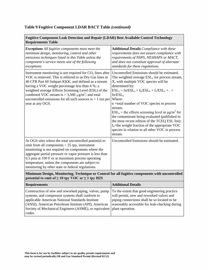
This form is for use by facilities subject to air quality permit requirements and may be revised periodically.Oil and Gas Standard Permit (Revised 02/12)
Table 9 Fugitive Component LDAR BACT Table (continued) Fugitive Component Leak Detection and Repair (LDAR) Best Available Control Technology Requirements Table
Exceptions All fugitive components must meet the minimum design, monitoring, control and other emissions techniques listed in this Table unless the component’s service meets one of the following exceptions:
Additional Details Compliance with these requirements does not assure compliance with requirements of NSPS, NESHAPS or MACT, and does not constitute approval of alternate standards for these regulations.
Instrument monitoring is not required for CO2 lines after VOC is removed. This is referred to as Dry Gas lines in 40 CFR Part 60 Subpart KKK, and defined as a stream having a VOC weight percentage less than 4 %; a weighted average Effects Screening Level (ESL) of the combined VOC stream is > 3,500 g/m3; and total uncontrolled emissions for all such sources is < 1 ton per year at any OGS.
Uncontrolled Emissions should be estimated. The weighted average ESLx for process stream, X, with multiple VOC species will be determined by: ESLx = fa/ESLa + fb/ESLb + fc/ESLc + . + fn/ESLn Where: n =total number of VOC species in process stream; ESLn = the effects screening level in μg/m3 for the contaminant being evaluated (published in the most recent edition of the TCEQ ESL list); fn=the weight fraction of the appropriate VOC species in relation to all other VOC in process stream.
At OGS sites where the total uncontrolled potential to emit from all components < 25 tpy, instrument monitoring is not required on components where the aggregate partial pressure or vapor pressure is less than 0.5 psia at 100 F or at maximum process operating temperature, unless the components are subject to monitoring by other state or federal regulations.
Uncontrolled Emissions should be estimated.
Minimum Design, Monitoring, Technique or Control for all fugitive components with uncontrolled potential to emit of ≥ 10 tpy VOC or ≥ 1 tpy H2S
Requirements Additional Details
Construction of new and reworked piping, valves, pump systems, and compressor systems shall conform to applicable American National Standards Institute (ANSI), American Petroleum Institute (API), American Society of Mechanical Engineers (ASME), or equivalent codes.
To the extent that good engineering practice will permit, new and reworked valves and piping connections shall be so located to be reasonably accessible for leak-checking during plant operation.

This form is for use by facilities subject to air quality permit requirements and may be revised periodically.Oil and Gas Standard Permit (Revised 02/12)
Table 9 Fugitive Component LDAR BACT Table (continued)
Minimum Design, Monitoring, Technique or Control for all fugitive components with uncontrolled potential to emit of ≥ 10 tpy VOC or ≥ 1 tpy H2S
Requirements Additional Details
New and reworked underground process pipelines shall contain no buried valves such that fugitive emission monitoring is rendered impractical. New and reworked piping connections shall be welded or flanged. Screwed connections are permissible only on piping smaller than two-inch diameter. Gas or hydraulic testing of the new and reworked piping connections at no less than operating pressure shall be performed prior to returning the components to service or they shall be monitored for leaks using an approved gas analyzer within 15 days of the components being returned to service. Where technically feasible new and reworked components may be screened for leaks with a soap bubble test within 8 hours of being returned to service in lieu of instrument testing. Adjustments shall be made as necessary to obtain leak-free performance.
Each open-ended valve or line shall be equipped with an appropriately sized cap, blind flange, plug, or a second valve to seal the line so that no leakage occurs. Except during sampling, both valves shall be closed.
If the removal of a component for repair or replacement results in an open ended line or valve, it is exempt from the requirement to install a cap, blind flange, plug, or second valve for 72 hours. If the repair or replacement is not completed within 72 hours, the permit holder must complete either of the following actions within that time period: the line or valve must have a cap, blind flange, plug, or second valve installed; or the open-ended valve or line shall be monitored once for leaks above background for a plant or unit turnaround lasting up to 45 days with an approved gas analyzer and the results recorded. For all other situations, the open-ended valve or line shall be monitored once at the end of the 72 hour period following the creation of the open ended line and monthly thereafter with an approved gas analyzer and the results recorded. For turnarounds and all other situations, leaks are indicated by readings 20 ppmv above background and must be repaired within 24 hours or a cap, blind flange, plug, or second valve must be installed on the line or valve.

This form is for use by facilities subject to air quality permit requirements and may be revised periodically.Oil and Gas Standard Permit (Revised 02/12)
Table 9 Fugitive Component LDAR BACT Table (continued)
Minimum Design, Monitoring, Technique or Control for all fugitive components with uncontrolled potential to emit of ≥ 10 tpy VOC or ≥ 1 tpy H2S
Requirements Additional Details
Components shall be inspected by visual, audible, and/or olfactory means at least weekly by operating personnel walk-through.
Accessible valves shall be monitored by leak-checking for fugitive emissions quarterly using an approved gas analyzer. Sealless/leakless valves (including, but not limited to, welded bonnet bellows and diaphragm valves) and relief valves equipped with a rupture disc upstream or venting to a control device are not required to be monitored. If an unsafe-to-monitor valve is not considered safe to monitor within a calendar year, then it shall be monitored as soon as possible during safe-to-monitor times. A difficult-to-monitor component for which quarterly monitoring is specified may instead be monitored annually.
Sealless/leakless valves and relief valves equipped with rupture disc or venting to a control device and exempted from instrument monitoring are not counted in the fugitive emissions estimates. See Table 7 Sampling and Demonstrations of Compliance for Fugitive and LDAR Analyzer requirements. See Table 8, Monitoring and Records Demonstrations to identify Difficult-to-monitor and unsafe-to-monitor valves.
For valves equipped with rupture discs, a pressure-sensing device shall be installed between the relief valve and rupture disc to monitor disc integrity.
All leaking discs shall be replaced at the earliest opportunity but no later than the next process shutdown.
All pump, compressor and agitator seals shall be monitored quarterly with an approved gas analyzer or be equipped with a shaft sealing system that prevents or detects emissions of VOC from the seal. Seal systems designed and operated to prevent emissions or seals equipped with an automatic seal failure detection and alarm system need not be instrument monitored. Seal systems that prevent emissions may include (but are not limited to) dual pump seals with barrier fluid at higher pressure than process pressure or seals degassing to vent control systems kept in good working order. Submerged pumps or sealless pumps (including, but not limited to, diaphragm, canned, or magnetic-driven pumps) may be used to satisfy the requirements of this condition and need not be monitored.
Pumps compressor and agitator seals that prevent leaks or direct emissions from the seals to control and are exempt from instrument monitoring are not counted in the fugitive emissions estimates. Equipment equipped with alarms would still be counted. See Table 7 Sampling and Demonstrations of Compliance for Fugitive and LDAR Analyzer requirements.

This form is for use by facilities subject to air quality permit requirements and may be revised periodically.Oil and Gas Standard Permit (Revised 02/12)
Table 9 Fugitive Component LDAR BACT Table (continued)
Minimum Design, Monitoring, Technique or Control for all fugitive components with uncontrolled potential to emit of ≥ 10 tpy VOC or ≥ 1 tpy H2S
Requirements Additional Details
For a site where the total uncontrolled potential to emit from all components is < 25 tpy; Components found to be emitting VOC in excess of 10,000 parts per million by volume (ppmv) using EPA Method 21, found by visual inspection to be leaking (e.g. whistling, dripping or blowing process fluids or emitting hydrocarbon or H2S odors) or found leaking using the Alternative Work Practice in 40 CFR §60.18(g) - (i) shall be considered to be leaking and shall be repaired, replaced, or tagged as specified. A first attempt to repair the leak must be made within 5 days. A leaking component shall be repaired as soon as practicable, but no later than 15 days after the leak is found. If the repair of a component would require a unit shutdown, the repair may be delayed until the next scheduled shutdown. All leaking components which cannot be repaired until a scheduled shutdown shall be identified for such repair by tagging.
Components subject to routine instrument monitoring with an approved gas analyzer under this leak definition my claim a 75% emission reduction credit when evaluating controlled fugitive emission estimates. This reduction credit does not apply when evaluating uncontrolled emission or to any component not measured with an instrument quarterly, but is allowed for all components monitored by the Alternative Work Practice. See Table 7 Sampling and Demonstrations of Compliance for Fugitive and LDAR Analyzer requirements
Components not subject to a instrument monitoring program but found to be emitting VOC in excess of 10,000 ppmv using EPA Method 21, found by audio, visual or olfactory inspection to be leaking (e.g. whistling, dripping or blowing process fluids or emitting hydrocarbon or H2S odors) shall be considered to be leaking and shall be repaired, replaced, or tagged as specified. All components are subject to monitoring when using the Alternative Work Practice in 40 CFR §60.18(g) - (i).
At the discretion of the TCEQ Executive Director or designated representative, early unit shutdown or other appropriate action may be required based on the number and severity of tagged leaks awaiting shutdown.

This form is for use by facilities subject to air quality permit requirements and may be revised periodically.Oil and Gas Standard Permit (Revised 02/12)
Table 9 Fugitive Component LDAR BACT Table (continued)
Minimum Design, Monitoring, Technique or Control for all fugitive components with uncontrolled potential to emit of ≥ 25 tpy or ≥ 5 tpy H2S
Requirements Additional Details
For a site where the total uncontrolled potential to emit from all components is ≥ 25 tpy; All the requirements for < 25tpy VOC above apply, except valves found to be emitting VOC in excess of 500 ppmv using EPA Method 21, found by audio, visual or olfactory inspection to be leaking (e.g. whistling, dripping or blowing process fluids or emitting hydrocarbon or H2S odors) or found leaking using the Alternative Work Practice in 40 CFR §60.18(g) - (i) shall be considered to be leaking and shall be repaired, replaced, or tagged as specified and Pump, compressor, and agitator seals found to be emitting VOC in excess of 2,000 ppmv using EPA Method 21, found by audio, visual or olfactory inspection to be leaking (e.g. whistling, dripping or blowing process fluids or emitting hydrocarbon or H2S odors) or found leaking using the Alternative Work Practice in 40 CFR §60.18(g) - (i) shall be considered to be leaking and shall be repaired, replaced, or tagged as specified.
Components subject to routine instrument monitoring under this leak definition my claim a 97% emission reduction credit for valves and an 85% emission reduction credit for pump, compressor and agitator seals when evaluating controlled fugitive emission estimates. This reduction credit does not apply when evaluating uncontrolled emission or to any component not measured with an instrument quarterly. See Table 7 Sampling and Demonstrations of Compliance for Fugitive and LDAR Analyzer requirements.
LDAR Monitoring Options
Any site may reduce the controlled fugitive emission estimates by including components not required to be monitored in the quarterly instrument monitoring program or applying the lower leak definition of the more stringent program as appropriate.
Quarterly monitoring at a leak definition of 10,000 ppmv would equate to a 75% emission reduction credit when evaluating controlled fugitive emission estimates for the component. Quarterly monitoring at a leak definition of 500 ppmv would equate to a 97% emission reduction credit for valves, flanges and connectors, a 93% emission reduction credit for pumps, and a 95% emission reduction credit for compressor, agitator seals and other component groups when evaluating controlled fugitive emission estimates. This reduction credit does not apply when evaluating uncontrolled emission or to any component not measured with an instrument quarterly. See Table 7 Sampling and Demonstrations of Compliance for Fugitive and LDAR Analyzer requirements.
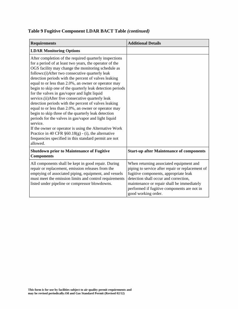
This form is for use by facilities subject to air quality permit requirements and may be revised periodically.Oil and Gas Standard Permit (Revised 02/12)
Table 9 Fugitive Component LDAR BACT Table (continued)
Requirements Additional Details
LDAR Monitoring Options
After completion of the required quarterly inspections for a period of at least two years, the operator of the OGS facility may change the monitoring schedule as follows:(i)After two consecutive quarterly leak detection periods with the percent of valves leaking equal to or less than 2.0%, an owner or operator may begin to skip one of the quarterly leak detection periods for the valves in gas/vapor and light liquid service.(ii)After five consecutive quarterly leak detection periods with the percent of valves leaking equal to or less than 2.0%, an owner or operator may begin to skip three of the quarterly leak detection periods for the valves in gas/vapor and light liquid service. If the owner or operator is using the Alternative Work Practice in 40 CFR §60.18(g) - (i), the alternative frequencies specified in this standard permit are not allowed.
Shutdown prior to Maintenance of Fugitive Components
Start-up after Maintenance of components
All components shall be kept in good repair. During repair or replacement, emission releases from the emptying of associated piping, equipment, and vessels must meet the emission limits and control requirements listed under pipeline or compressor blowdowns.
When returning associated equipment and piping to service after repair or replacement of fugitive components, appropriate leak detection shall occur and correction, maintenance or repair shall be immediately performed if fugitive components are not in good working order.

This form is for use by facilities subject to air quality permit requirements and may be revised periodically.Oil and Gas Standard Permit (Revised 02/12)
Table 10 Best Available Control Technology Requirements
Source or Facility
Air Contaminant
Minimum Acceptable Design, Control or Technique, Control Efficiencies, and Other Details during Production Operations
Combined Control Requirements
< 25 tpy VOC No add on control is required if the continuous and periodic vents from all units, vessels and equipment (including normal operation process blow downs) is less than 25 tons of VOC per year.
≥ 25 tpy VOC All continuous and periodic vents on process vessels and equipment with potential emissions containing ≥ 1% VOC at any time must be captured and directed to a control device listed in the Control Device BACT Table with a minimum design control efficiency of at least 95%, if the sum of the uncontrolled PTE of the vents at the site will equal or exceed 25 tons of VOC per year. A site total potential to emit of 1 tpy of VOC from vent gas streams may be exempted from this control requirement.
Glycol Dehydration Unit
Uncontrolled PTE < 10 tpy VOC VOC, BTEX, H2S
No control is required. Condensers included in the equipment constructed must be maintained and operated as specified by the manufacturer or design engineering.
Uncontrolled PTE ≥ 10 tpy and < 50 tpy VOC VOC, BTEX, H2S
All non-combustion VOC emissions shall be routed to a vapor recovery unit (VRU), the unit reboiler, or to an appropriate control device listed in the Control Device BACT Table. This includes the emissions from the condenser vent. Liquid waste or product material captured by a condenser must be enclosed and transferred to a unit compliant with the requirements of this table and the condenser must meet the requirements listed in the Control Device BACT Table with a minimum design control efficiency of 80%. For condensors, greater efficiencies may be claimed where enhanced monitoring and testing are applied following Table 7. If the unit reboiler is used to control the VOC emissions from the dehydrator (e.g. to control the condenser vent and the flash tank if one is present) the unit must be designed to efficiently combust those vented VOCs at least 50% of the time the unit is operated.
Uncontrolled PTE ≥ 50 tpy VOC VOC, BTEX, H2S
All non-combustion VOC emissions shall be captured and directed to an appropriate control device listed in the Control Device BACT Table with a minimum design control efficiency of at least 95%.
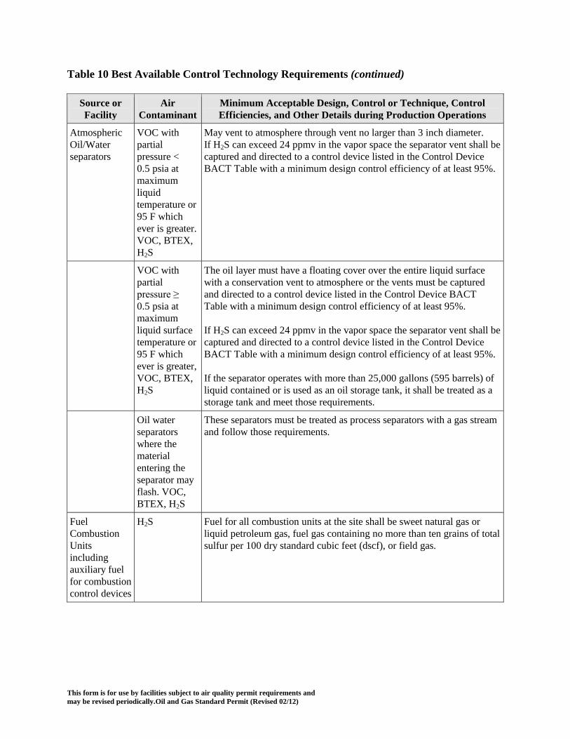
This form is for use by facilities subject to air quality permit requirements and may be revised periodically.Oil and Gas Standard Permit (Revised 02/12)
Table 10 Best Available Control Technology Requirements (continued)
Source or Facility
Air Contaminant
Minimum Acceptable Design, Control or Technique, Control Efficiencies, and Other Details during Production Operations
Atmospheric Oil/Water separators
VOC with partial pressure < 0.5 psia at maximum liquid temperature or 95 F which ever is greater. VOC, BTEX, H2S
May vent to atmosphere through vent no larger than 3 inch diameter. If H2S can exceed 24 ppmv in the vapor space the separator vent shall be captured and directed to a control device listed in the Control Device BACT Table with a minimum design control efficiency of at least 95%.
VOC with partial pressure ≥ 0.5 psia at maximum liquid surface temperature or 95 F which ever is greater, VOC, BTEX, H2S
The oil layer must have a floating cover over the entire liquid surface with a conservation vent to atmosphere or the vents must be captured and directed to a control device listed in the Control Device BACT Table with a minimum design control efficiency of at least 95%. If H2S can exceed 24 ppmv in the vapor space the separator vent shall be captured and directed to a control device listed in the Control Device BACT Table with a minimum design control efficiency of at least 95%. If the separator operates with more than 25,000 gallons (595 barrels) of liquid contained or is used as an oil storage tank, it shall be treated as a storage tank and meet those requirements.
Oil water separators where the material entering the separator may flash. VOC, BTEX, H2S
These separators must be treated as process separators with a gas stream and follow those requirements.
Fuel Combustion Units including auxiliary fuel for combustion control devices
H2S Fuel for all combustion units at the site shall be sweet natural gas or liquid petroleum gas, fuel gas containing no more than ten grains of total sulfur per 100 dry standard cubic feet (dscf), or field gas.
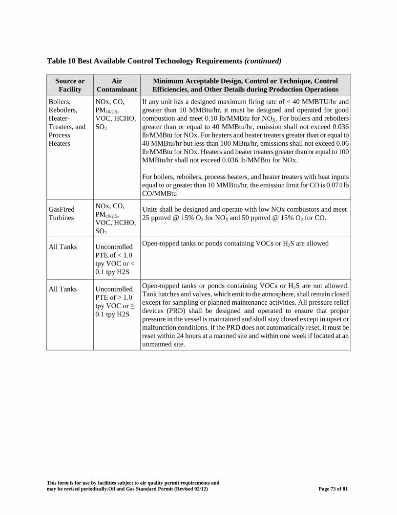
This form is for use by facilities subject to air quality permit requirements and may be revised periodically.Oil and Gas Standard Permit (Revised 02/12) Page 73 of 81
Table 10 Best Available Control Technology Requirements (continued)
Source or Facility
Air Contaminant
Minimum Acceptable Design, Control or Technique, Control Efficiencies, and Other Details during Production Operations
Boilers, Reboilers, Heater-Treaters, and Process Heaters
NOx, CO, PM10/2.5, VOC, HCHO, SO2
If any unit has a designed maximum firing rate of < 40 MMBTU/hr and greater than 10 MMBtu/hr, it must be designed and operated for good combustion and meet 0.10 lb/MMBtu for NOX. For boilers and reboilers greater than or equal to 40 MMBtu/hr, emission shall not exceed 0.036 lb/MMBtu for NOx. For heaters and heater treaters greater than or equal to 40 MMBtu/hr but less than 100 MBtu/hr, emissions shall not exceed 0.06 lb/MMBtu for NOx. Heaters and heater treaters greater than or equal to 100 MMBtu/hr shall not exceed 0.036 lb/MMBtu for NOx. For boilers, reboilers, process heaters, and heater treaters with heat inputs equal to or greater than 10 MMBtu/hr, the emission limit for CO is 0.074 lb CO/MMBtu
GasFired Turbines
NOx, CO, PM10/2.5, VOC, HCHO, SO2
Units shall be designed and operate with low NOx combustors and meet 25 ppmvd @ 15% O2 for NOX and 50 ppmvd @ 15% O2 for CO.
All Tanks Uncontrolled PTE of < 1.0 tpy VOC or < 0.1 tpy H2S
Open-topped tanks or ponds containing VOCs or H2S are allowed
All Tanks Uncontrolled PTE of ≥ 1.0 tpy VOC or ≥ 0.1 tpy H2S
Open-topped tanks or ponds containing VOCs or H2S are not allowed. Tank hatches and valves, which emit to the atmosphere, shall remain closed except for sampling or planned maintenance activities. All pressure relief devices (PRD) shall be designed and operated to ensure that proper pressure in the vessel is maintained and shall stay closed except in upset or malfunction conditions. If the PRD does not automatically reset, it must be reset within 24 hours at a manned site and within one week if located at an unmanned site.

This form is for use by facilities subject to air quality permit requirements and may be revised periodically.Oil and Gas Standard Permit (Revised 02/12)
Table 10 Best Available Control Technology Requirements (continued)
Source or Facility
Air Contaminant
Minimum Acceptable Design, Control or Technique, Control Efficiencies, and Other Details during Production Operations
Process Separators, Crude oil, Condensate, Treatment chemicals, Produced water, Fuel, Slop/Sump Oil and any other storage tanks or vessels that contain a VOC or a film of VOC on the surface of water.
VOC with partial pressure < 0.5 psia at maximum liquid surface temperature or 95 F which ever is greater, or with uncontrolled PTE of < 5 tpy VOC from working and breathing losses, including flash emissions VOC, BTEX, H2S
All storage tanks with a storage capacity greater than 500 gallons must be submerged fill. Existing tanks and vessels (including temporary liquid storage tanks) which are not increasing emissions at an OGS shall also meet this requirement no later than 180 days after a registration renewal as of January 1, 2016
VOC with partial pressure ≥ 0.5 psia at maximum liquid surface temperature or 95 F (which ever is greater), and with uncontrolled PTE of < 5 tpy from working and breathing losses, including flash emissions VOC, BTEX, H2S
All storage tanks with a storage capacity greater than 500 gallons must be submerged fill. Un-insulated tank exterior surfaces exposed to the sun shall be of a color that minimizes the effects of solar heating (including, but not limited to, white or aluminum). To meet this requirement the solar absorptance should be 0.43 or less, as referenced in Table 7.1-6 in AP-42. Paint shall be maintained in good condition. If a new or modified tank cannot be painted white or other reflective color, then another control device may be used to control emissions. Exceptions to the color requirement include the following: (A) Up to 10% of the external surface area of the roof or walls of the tank or vessel may be painted with other colors to allow for identifying information or aethestic purposes; and (B) If a local, state or federal law or ordinance or private contract which predates this standard permit’s effective date establishes in writing tank and vessel colors other than white. If applicable, a copy of this documentation must be provided to the commission upon registration. (C) Tanks and vessels purposefully darkened to create the process reaction and help condense liquids from being entrained in the vapor. Existing tanks and vessels (including temporary liquid storage tanks) which are not increasing emissions at an OGS using shall also meet this requirement no later than 180 days after a registration renewal as of January 1, 2016.

This form is for use by facilities subject to air quality permit requirements and may be revised periodically.Oil and Gas Standard Permit (Revised 02/12)
Table 10 Best Available Control Technology Requirements (continued)
Source or Facility
Air Contaminant
Minimum Acceptable Design, Control or Technique, Control Efficiencies, and Other Details during Production Operations
VOC with uncontrolled PTE of ≥ 5 tpy
Vents Vents shall be captured and directed to an appropriate control device as listed in standard permit (e) BMP and BACT. Un-insulated tank exterior surfaces exposed to the sun shall be of a color that minimizes the effects of solar heating (including, but not limited to, white or aluminum). To meet this requirement the solar absorptance should be 0.43 or less, as referenced in Table 7.1-6 in AP-42. Paint shall be maintained in good condition. Exceptions to the color requirement include the following: (A) Up to 10% of the external surface area of the roof or walls of the tank or vessel may be painted with other colors to allow for identifying information or aethestic purposes; and (B) If a local, state or federal law or ordinance or private contract which predates this standard permit’s effective date establishes in writing tank and vessel colors other than white. If applicable, a copy of this documentation must be provided to the commission upon registration. (C) Tanks and vessels purposefully darkened to create the process reaction and help condense liquids from being entrained in the vapor. Existing tanks and vessels (including temporary liquid storage tanks) which are not increasing emissions at an OGS using shall also meet this requirement no later than 180 days after a registration renewal as of January 1, 2016.
Truck Loading VOC with partial pressure < 0.5 psia at maximum liquid surface temperature or 95 F whichever is greater, or with uncontrolled PTE of < 5 tpy VOC VOC, BTEX, H2S
Loading is recommended to be performed with submerged filling, or vapor balancing back to the tank and any subsequent recovery or control device.

This form is for use by facilities subject to air quality permit requirements and may be revised periodically.Oil and Gas Standard Permit (Revised 02/12)
Table 10 Best Available Control Technology Requirements (continued)
Source or Facility
Air Contaminant
Minimum Acceptable Design, Control or Technique, Control Efficiencies, and Other Details during Production Operations
VOC with partial pressure ≥ 0.5 psia at maximum liquid surface temperature or 95 F which ever is greater VOC, BTEX, H2S
Splash loading and uncontrolled vacuum truck loading is not allowed. Loading shall be performed with a control effectiveness of at least 42% as compared to splash loading. Loading may occur by submerged filling or equivalent prevention or recovery technique as listed in Table 10.
VOC with uncontrolled PTE of ≥ 5 tpy VOC VOC, BTEX, H2S
Loading vapors shall be captured and directed to an appropriate control device listed in the Control Device BACT Table with a minimum design control efficiency of at least 98%, routed to a vapor recovery unit (VRU) with a control effectiveness of at least 95%, or vapor balanced back to the delivering storage tank equipped with a VRU, or connected to a control device listed in the Control Device BACT Table with a minimum design control efficiency of at least 95%.
Controlled Loading
Where loading control is required, the collection or capture system must be connected to the tank truck so all displaced vapors are directed to the control device and the control device is operational before loading is commenced. When properly connected the capture efficiency will be assumed to be 70% efficient at capturing the displaced truck vapors. The capture efficiency may be assumed to be 98.7 percent efficient when the tanker truck has certification that the tank has passed vapor-tightness testing within the last 12 months using the methods described in 40 CFR 60, Subpart XX. The capture efficiency may be assumed to be 99.2 percent efficient when the tanker truck has certification that the tank has passed vapor-tightness testing within the last 12 months using the methods described in 40 CFR 63, Subpart R. Loading shall be discontinued when liquid or gas leaks from the loading or collection system are observed.

This form is for use by facilities subject to air quality permit requirements and may be revised periodically.Oil and Gas Standard Permit (Revised 02/12)
Table 10 Best Available Control Technology Requirements (continued)
Source or Facility
Air Contaminant
Minimum Acceptable Design, Control or Technique, Control Efficiencies, and Other Details during Production Operations
Cooling Tower Heat Exchange System
VOC, BTEX, PM10/2.5
Heat exchange systems must be non-contact design (i.e. designed and operated to avoid direct contact with gaseous or liquid process streams containing VOC, H2S, halogens or halogen compounds, cyanide compounds, inorganic acids, or acid gases). Systems with heat exchangers that cool a fluid with VOC shall meet the following: The cooling water must be at a higher pressure than the process fluid in the heat exchangers or the cooling tower water must be monitored monthly for VOC emissions using TCEQ Sampling Procedures Manual, Appendix P dated January 2003 or a later edition. Equipment shall be maintained so as to minimize VOC emissions into the cooling water. Cooling water VOC concentrations greater than 0.08 ppmw indicate faulty equipment. If the repair of a heat exchanger would require a unit shutdown that would create more emissions than the repair would eliminate, the repair may be delayed until the next planned shutdown or 180 days if no shutdowns are scheduled. Cooling towers shall be designed and operated with properly functioning drift eliminators. New cooling towers shall be designed with drift eliminators designed to meet ≤ 0.001% drift.
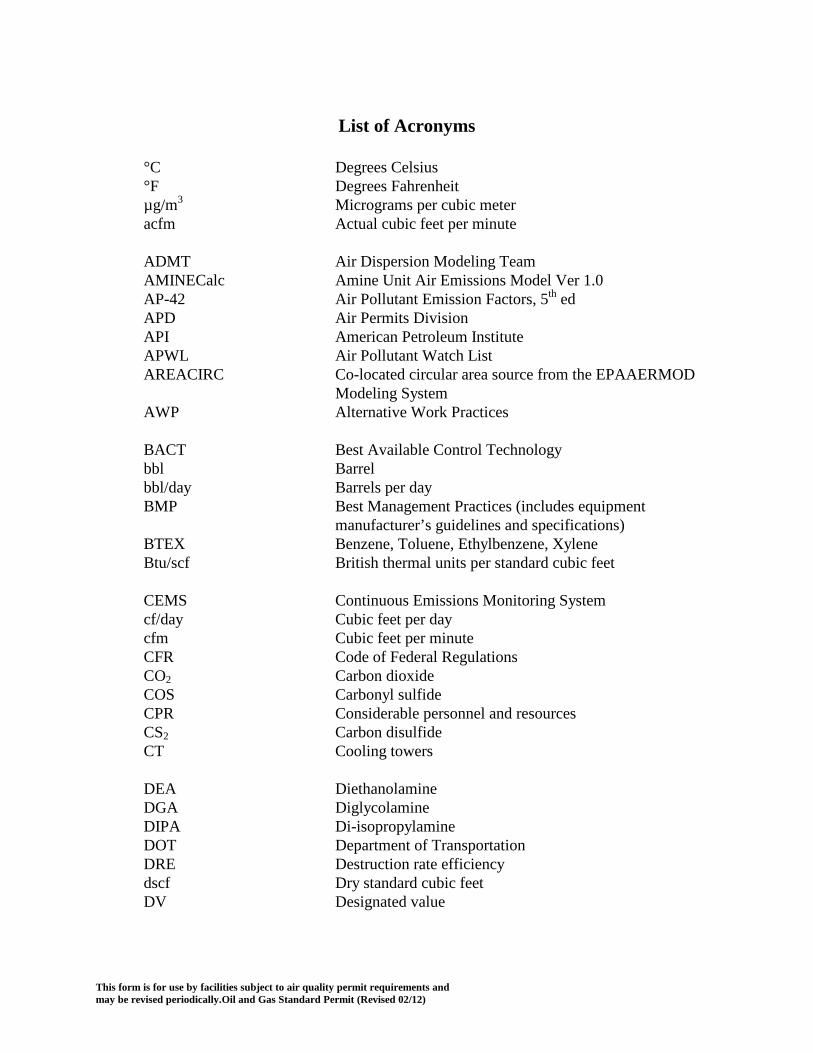
This form is for use by facilities subject to air quality permit requirements and may be revised periodically.Oil and Gas Standard Permit (Revised 02/12)
List of Acronyms
°C Degrees Celsius °F Degrees Fahrenheit µg/m3 Micrograms per cubic meter acfm Actual cubic feet per minute ADMT Air Dispersion Modeling Team AMINECalc Amine Unit Air Emissions Model Ver 1.0 AP-42 Air Pollutant Emission Factors, 5th ed APD Air Permits Division API American Petroleum Institute APWL Air Pollutant Watch List AREACIRC Co-located circular area source from the EPAAERMOD
Modeling System AWP Alternative Work Practices BACT Best Available Control Technology bbl Barrel bbl/day Barrels per day BMP Best Management Practices (includes equipment
manufacturer’s guidelines and specifications) BTEX Benzene, Toluene, Ethylbenzene, Xylene Btu/scf British thermal units per standard cubic feet CEMS Continuous Emissions Monitoring System cf/day Cubic feet per day cfm Cubic feet per minute CFR Code of Federal Regulations CO2 Carbon dioxide COS Carbonyl sulfide CPR Considerable personnel and resources CS2 Carbon disulfide CT Cooling towers DEA Diethanolamine DGA Diglycolamine DIPA Di-isopropylamine DOT Department of Transportation DRE Destruction rate efficiency dscf Dry standard cubic feet DV Designated value

This form is for use by facilities subject to air quality permit requirements and may be revised periodically.Oil and Gas Standard Permit (Revised 02/12) Page 79 of 81
List of Acronyms(continued) E Maximum acceptable emission rate (lb/hr) EF Emission factor EFR External floating roof tank Emax Maximum acceptable emission rate (lb/hr) EPA Environmental Protection Agency EPN Emission point number ESL Effects screening level FR Federal Register ft Feet ft/sec Feet per second gal/wk Gallons per week gal/yr Gallons per year GLCmax Max predicted ground-level concentration GOP General Operating Permit H2S Hydrogen sulfide HAP Hazardous air pollutant HB House Bill HCl Hydrogen chloride hp Horsepower hr Hour HRVOC Highly reactive volatile organic compounds HYSIM® Hydrologic Simulation Model computer program HYSIS® Process simulator computer program ICE Internal combustion engine IFR Internal floating roof tank IR Infrared ISCST3 Industrial Source Complex Short-term Model V02035 LACT Lease automatic custody transfer unit lb Pound lb/hr Pounds per hour lb/MMBtu Pounds per million British thermal units lbs/day Pounds per day

This form is for use by facilities subject to air quality permit requirements and may be revised periodically.Oil and Gas Standard Permit (Revised 02/12) Page 80 of 81
List of Acronyms(continued) LDAR Leak detection and repair LL Loading losses LPG Liquid petroleum gas LT/D Long ton per day m/sec Meters per second MACT Maximum Available Control Technology MDEA Methyl-diethanolamine MEA Monoethanol amine MERA Modeling and Effects Review Applicability MMBtu Million British thermal units MMBtu/hr Million British thermal units per hour MMCFD Million cubic feet per day MSS Maintenance, start-up, and shutdown NAAQS National Ambient Air Quality Standards NESHAP National Emission Standards for Hazardous Air Pollutants NGL Natural gas liquids NNSR Nonattainment New Source Review NO2 Nitrogen dioxide NOx Oxides of nitrogen NSPS New Source Performance Standards NSR New Source Review O2 Oxygen (molecular form) OGS Oil and gas site PBR Permit by Rule PM10 Particulate matter less than or equal to 10 microns POC Products of combustion ppm Parts per million Ppmvd Parts per million by volume, dry PROSIM® DOS based process simulator computer program PSD Prevention of Significant Deterioration psi Pounds per square inch psia Pounds per square inch, absolute psig Pounds per square inch, gage

This form is for use by facilities subject to air quality permit requirements and may be revised periodically.Oil and Gas Standard Permit (Revised 02/12) Page 81 of 81
List of Acronyms(continued) RICE Reciprocating internal combustion engine RVP Reid vapor pressure scfh Standard cubic feet per hour scfm Standard cubic feet per minute scmd Standard cubic feet per day SCREEN3 Air dispersion modeling computer program forwindows,
Version 5.0. BEE-line Software c1998-2002 SE Standard Exemption SIC Standard Industrial Classification System SO2 Sulfur dioxide SOP Site Operating Permit Standard permit Standard Permit SRU Sulfur recovery unit T&S Transfer and storage TAC Texas Administrative Code TCAA Texas Clean Air Act TCEQ Texas Commission on Environmental Quality TEA Triethanolamine THSC Texas Health and Safety Code tpy Tons per year V-B Vasquez-Beggs correlation equation VOC Volatile organic compounds VRU Vapor recovery unit or system WINSIM® Windows process simulator computer program