Embed Size (px)
Citation preview

TCD110 SeriesDigital Force Tester (110 lbf, 50 kgf, 500N)
Features Advanced Yet Simple to Use Test Setups - Limit Testing (Load, Distance, Time) - Break Testing - Cyclic & Loop Testing -Multi-Stage/UserDefinedTesting - Height Measurement Advanced Operator Control Console - Simple Operation with Menus, Templates & Prompts - Secure Access - Tabular and Graphical Results - Embedded SPC - Ergonomic Design, Position for User Comfort - Large, Color Display - No Computer Required PID Closed-Loop Motion Control - Precision Position Accuracy - Speed Accuracy Better than 1% 1000Hz Data Sampling and USB Output - Save Data to Flash Drive - Export Data Directly to Excel or OLE2 Formats Large Working Area - Ideal for Large and Small Samples - T-Slot Table Design Supports Custom Fixturing Barcode Automatic Operation 1 Year Warranty
Specification SheetSS-FM-3001-0608
June 2008
The CHATILLON® TCD110 Series is an advanced force testing system optimized for production, quality control and engineering applications. The TCD System consists of a powerful, yet easy-to-use console; a rugged frame with high performance, closed-loop motion control; and an intelligent load sensing system with measuring accuracies better than 0.1% full scale. The TCD console features a high resolution color graphical display featuring menus, function and numeric keys and status indicators that assist the user in setup, operation and analysis. Information may be displayed in large-format tabular and graphical formats for easy viewing. The frame operates from 0.001 to 20.0-inches per minute (0.02 to 510 mm/minute) and employs an advanced closed-loop PID controller for precision travel (accuracy better than 0.25% unloaded), ideal for applications such as spring testing where exact distance control is required. TheTCDSystempermitstheusertomeasureheightsbasedonadatumorabsoluteposition.Deflectioncompensationisstandard.Standardtestsetupsfor load limits, distance limits, time limits, break tests, rupture tests, cycling and loop tests are included. No computer software is necessary.
www.dmm.ca1-866-960-9400
PRECISION IS OUR VISIONDigital Measurement Metrology, Inc
TM
Digital Measurement Metrology, Inc

TCD110 Series Specifications
Load Capacity- 110 lbf - 50 kgf- 500 N
Configurable Speed Range- 0.001 to 20.0 inch/minute- 0.02 to 510 mm/minute- Independent Return Speed- Independent Multi-Stage Speeds
Load Measurement System- TLC Series Load Sensors - Auto-Recognition, “Plug & Test”- Sensor Overload History Log
Load Measurement System- Accuracy better than 0.1% Full Scale- Calibrate On-site to Better than 0.25% Reading- Measuring system meets or exceeds the following: ASTM E4, BS 1610, DIN 51221, ISO 7500-1, EN 10002-2 AFNOR A03-501 (AMETEKrecommendssystemverification on-site at the time of installation by an authorized Chatillon Representative, as required by ASTM E4 and ISO 7500-1)
Strain Measurement System- Position accuracy better than 0.001 in (0.02mm) or 0.05% displacement (whichever is greater) - Strain measurement system meets or exceeds the following: ASTM E83, BS 3846, ISO 9513, EN 10002-4- DeflectionCompensationStandard
Speed Accuracy- Better than 1% Full Scale
Distance Accuracy- Better than 0.25% of reading unloaded
Crosshead Travel- 15-inch (380mm)
Display Language Options- English- Chinese(Simplified)- Chinese (Traditional)- French- German- Korean- Portuguese- Russian- Spanish- Turkish
Data Sampling- 1000Hz- User Selectable Sampling/Filters (1-1000 Hz)
Data Output- USB Serial Data and RS232 Data Output Save Data Directly to USB Flash Drive Interface to USB Serial Devices, e.g. Barcode Scanner/ Reader, Printers, Keyboards, Hubs - Export Data to Excel or any OLE2 Compatible Platform - Save Test Results Locally in Console Memory
Test Setups- Load Limit - Distance Limit- Time Limit- Break or Rupture- Cycle or Loop- Multi-Stage(Defineacustomtestwithmultiplestages)
Operating Temperature- 40°F to 110°F (5°C to 45°C)
Storage Temperature- 0° to 130°F (-17° to 54°C)
Relative Humidity- 20% to 85%
Conformance - The system conforms to all relevant European standards and carries the CE mark.
Single Phase Voltage- 100, 120, 220 or 240Vac +10%, 47 to 63Hz. Power must be free of spikes, surges, and sags exceeding 10% of the average voltage.
Weight- 65 lbs 30 kg)
Shipping Weight- 80 lbs (36 kg)
Warranty- 1 year
ThesespecificationsweredevelopedinaccordancewithAMETEK’sstandardproceduresandaresubject to change without notice.
www.dmm.ca1-866-960-9400
PRECISION IS OUR VISIONDigital Measurement Metrology, Inc
TM
Digital Measurement Metrology, Inc

Features
Intelligent Universal InterfaceThe TCD Series console eliminates the need for a personal computer without compromising operational performance and capability. The TCD console serves as the primary operator interface for real-time setup, testing and analysis. A large 5 x 8-inch color graphic screen presents information in a clear, easy-to-read format. Menus and prompts are used during setup to assist the user. Data is displayed in tabular and graphical formats. Color is used to identify key status events or to inform theuserofspecificevents.Forexample,aloadbargraph displays during a test and displays green to indicate the sensor is measuring within its con-figuredrange.Thebargraphwillchangetoyellowto alert the operator that the sensor is performing near its capacity. The bargraph will change to red when the sensor is at an overload condition.
Function keys are mapped to the display prompts and serve to guide the user during testing and setup.Functionkeysmaybedefinedbytheuserto create “shortcuts” or “hot keys” to frequent operations.
Control keys are minimized to key functions and are large with excellent tactile feedback. Standard Test SetupThe TCD console is used to setup all testing. No computers or software required. The console contains these test categories: Limit Test, Break Test, Cycle Test and Multi-Stage Test.
Limit TestingYou can setup a test based on a load limit, distance limit or time limit in both tensile and compression directions. Results include the load at a distance limit, the distance at a load limit, the load at a time limit, the distance at a time limit, load average based on a time period.
Break TestingYou can perform break (tensile) or rupture (com-pression) testing. The break is defined as a percentage drop from the peak load measured. Results include the peak load, load at break/rup-ture, and distance at break/rupture.
Cycle TestingYou may perform cyclic testing based on a cycle countorcycletime.Resultsincludethefirstpeakand last peak as well as detained cycle information such as cycle time required. A countdown indicator displays the active cycle condition.
Multi-Stage TestingThemulti-stagesetupallowstheusertoconfigurevirtually any type of test setup imaginable. Each partofatestisdefinedasa“stage”.Eachstagecan be setup with its own independent load or dis-tance characteristic and speed. Multi-stage testing can be used for creep tests, load hold or distance hold tests, insertion/extraction tests, snap-on/off tests or other sophisticated test methods. You can configureawide rangeofwaveshapemethodsincluding sine, triangle, sawtooth, square, ramp and trapezoidal to your test sample. The user has total freedom to create the test movement required for testing their sample without the need for expensive 3rd-party software applications or validation requirements.
Spring TestingThe TCD Series includes a Height Mode of opera-tion ideal for performing sophisticated spring test-ing and Gage R&R testing. The height mode allows the user to measure the height of the spring prior to the test, perform pre-conditioning (scragging) and then measure the L1 and L2 limits to within 0.1% accuracy. Using the multi-stage function, you can test multiple test points ideal for characterizing a spring. Data sampling at 1000 samples per second can be saved and exported into Excel for analysis and report generation. The ease and simplicity of the TCD System is unmatched.
Ergonomic DesignThe TCD Console is mounted on the standard console mounting arm. The console can be located to provide ideal comfort for the user. The console can pivot, tilt, move up or down.
RESULTS DataLarge format characters make it easy to view your test result. Color is used to denote pass and fail results. Show a tensile test result for Test No. 3 where the break load was 12.40 lbf and distance was 0.877 inches.
Measuring to New HeightsThe TCD System can be set up in Height mode to provide exact height measurements of your samples. Ideal for spring testing, the system includes an automatic datum routine that can be used to determine heights based on the datum. Measurement accuracy is better than 0.001 inch (0.02mm).
www.dmm.ca1-866-960-9400
PRECISION IS OUR VISIONDigital Measurement Metrology, Inc
TM
Digital Measurement Metrology, Inc
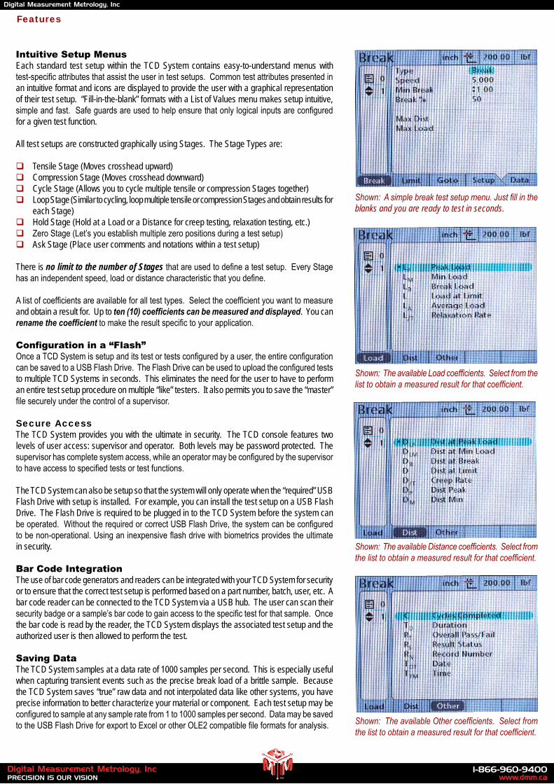
Intuitive Setup MenusEach standard test setup within the TCD System contains easy-to-understand menus with test-specificattributesthatassisttheuserintestsetups.Commontestattributespresentedinan intuitive format and icons are displayed to provide the user with a graphical representation of their test setup. “Fill-in-the-blank” formats with a List of Values menu makes setup intuitive, simpleandfast.Safeguardsareusedtohelpensurethatonlylogicalinputsareconfiguredfor a given test function.
All test setups are constructed graphically using Stages. The Stage Types are:
Tensile Stage (Moves crosshead upward) Compression Stage (Moves crosshead downward) Cycle Stage (Allows you to cycle multiple tensile or compression Stages together) Loop Stage (Similar to cycling, loop multiple tensile or compression Stages and obtain results for each Stage) Hold Stage (Hold at a Load or a Distance for creep testing, relaxation testing, etc.) ZeroStage(Let’syouestablishmultiplezeropositionsduringatestsetup) Ask Stage (Place user comments and notations within a test setup)
There is no limit to the number of Stagesthatareusedtodefineatestsetup.EveryStagehasanindependentspeed,loadordistancecharacteristicthatyoudefine.
Alistofcoefficientsareavailableforalltesttypes.Selectthecoefficientyouwanttomeasureand obtain a result for. Up to ten (10) coefficients can be measured and displayed. You can rename the coefficient tomaketheresultspecifictoyourapplication.
Configuration in a “Flash”OnceaTCDSystemissetupanditstestortestsconfiguredbyauser,theentireconfigurationcanbesavedtoaUSBFlashDrive.TheFlashDrivecanbeusedtouploadtheconfiguredteststo multiple TCD Systems in seconds. This eliminates the need for the user to have to perform an entire test setup procedure on multiple “like” testers. It also permits you to save the “master” filesecurelyunderthecontrolofasupervisor. Secure AccessThe TCD System provides you with the ultimate in security. The TCD console features two levels of user access: supervisor and operator. Both levels may be password protected. The supervisorhascompletesystemaccess,whileanoperatormaybeconfiguredbythesupervisortohaveaccesstospecifiedtestsortestfunctions.
The TCD System can also be setup so that the system will only operate when the “required” USB Flash Drive with setup is installed. For example, you can install the test setup on a USB Flash Drive. The Flash Drive is required to be plugged in to the TCD System before the system can beoperated.WithouttherequiredorcorrectUSBFlashDrive,thesystemcanbeconfiguredtobenon-operational.Usinganinexpensiveflashdrivewithbiometricsprovidestheultimatein security.
Bar Code IntegrationThe use of bar code generators and readers can be integrated with your TCD System for security or to ensure that the correct test setup is performed based on a part number, batch, user, etc. A bar code reader can be connected to the TCD System via a USB hub. The user can scan their securitybadgeorasample’sbarcodetogainaccesstothespecifictestforthatsample.Oncethe bar code is read by the reader, the TCD System displays the associated test setup and the authorized user is then allowed to perform the test.
Saving DataThe TCD System samples at a data rate of 1000 samples per second. This is especially useful when capturing transient events such as the precise break load of a brittle sample. Because the TCD System saves “true” raw data and not interpolated data like other systems, you have precise information to better characterize your material or component. Each test setup may be configuredtosampleatanysampleratefrom1to1000samplespersecond.DatamaybesavedtotheUSBFlashDriveforexporttoExcelorotherOLE2compatiblefileformatsforanalysis.
Shown: A simple break test setup menu. Just fill in the blanks and you are ready to test in seconds.
Shown: The available Load coefficients. Select from the list to obtain a measured result for that coefficient.
Shown: The available Distance coefficients. Select from the list to obtain a measured result for that coefficient.
Shown: The available Other coefficients. Select from the list to obtain a measured result for that coefficient.
Features
www.dmm.ca1-866-960-9400
PRECISION IS OUR VISIONDigital Measurement Metrology, Inc
TM
Digital Measurement Metrology, Inc

Create Tolerances for Your ResultsDisplay results data in a small format showing tolerance (pass/fail) limits. Example shows limits set at 5.00 lbf and 10.00 lbf. Actual break load was outside the limits, therefore the result is displayed in red indicating a failed test.
Graph Your ResultsLoad results data may be graphed based on time and distance. The number of data points that areusedtodrawthegrapharesetbytheuser.Upto1000datapointsmaybeconfigured.Thenavigation keys can be used to display a cross hair. Move the cross hair to view the precise measurementforeachdatapointsthatwasconfigured.YoumayoutputthedatapointsdirectlyintoExcelforanalysisortocreateamoredefinedgraphinavarietyofformats.
Embedded SPC CalculationsSelectingtheSTATSsoftkeyshowsthestatisticalresultsforthetestforeachcoefficient.Thisdisplay shows the load value (peak load for stage No. 1). The Maximum, Minimum, Range, Average (Mean), Standard Deviation and COV are calculated.
Comprehensive Result DisplaysOnce your test is completed, the TCD System will display comprehensive results based on thecoefficientsyouaskedfor.Youcanchangethesizeoftheresult,theorderitappearsonthe display, you can even create multiple screens for your results so that primary results are distinguished from secondary results.
Shown: A Cycle Test result showing the first and last peak load values with distance information. Time duration and number of cycles completed are also shown.
Shown: A Break Test shows the peal load with respect to the two setpoint limits that define a pass/fail condition.
Shown: A Load v Time graph showing the specific load value and distance values at the cross hair location.
Shown: A Break Test’s statistical results. Shown is the peak load for Test No. 2. Six tests were completed. Note that Test 5 was deleted by the user. The system maintain the Run history. A “Mark Deletion” option will maintain a deleted record to show that the operator deleted a test. This data is not included in the statisti-cal results.
Features
www.dmm.ca1-866-960-9400
PRECISION IS OUR VISIONDigital Measurement Metrology, Inc
TM
Digital Measurement Metrology, Inc

Features
Plug & Play SensorsThe TCD System uses our exclusive Chatillon TLC Series sensor technology. Sensors plug into the TCD Console and the console recognizes and automatically downloads all sensor characteristics. There are also safe guards that can help prevent an operator from using the incorrect sensor on a particular test. Plus the TCD System maintains a load history within memory and can display time-stamped overload events. Seven sensors ranging from 250g (0.5 lb) to 225 lb (100 kg) are available. These same load sensors can also be interchanged withtheChatillonDFS-R-NDSeriesforcegauges.Sensorscomestandardwithacertificateof calibration with NIST data and uncertainty. They can be calibrated to better than 0.1% full scale or 0.5% of indicated reading when calibrated on-site in accordance with ASTM E4 or ISO 7500-1.
Precision Crosshead ControlAn innovative thumbwheel is ideal for settingup your fixturing. Rotating the thumbwheelcauses the crosshead to move upward/downward. Rotate the thumbwheel slowly and the crosshead moves slowly. Rotate fast and the crosshead moves fast, up to 50 inches (1270mm) per minute.
Over-Travel LimitsDual over-travel limits, located on the front console, help prevent crosshead overshooting and sensor overloads. A graduated rule along the column can be used to preset these limits to specificdistances.
Pinch Load LimitsThe TCD System features a Pinch Load capability that allows you to enter a load value up to 15 lbf (7 kgf). When the machine is operated manually using the thumbwheel or DOWN key, the crosshead will stop moving when the system measures the pinch load value. This helps protect the user during a manual move.
Flexible MountingTheTCDSystem’sT-slottablecontainsmultiplestandardthroughholesformountingvarioustypesofthreadedfixturesandeye-endadapters.Thefixturemountingblockcanbeeasilypositioned to ensure proper alignment with the load measuring sensor.
We Speak Your LanguageThe TCD Console features multiple languages so your operators can perform tests and setups in the language they are most comfortable using. The following language sets are supplied standard:
English Chinese (Traditional) Chinese(Simplified) French German Korean Portuguese Russian Turkish
Other languages can be added as required.
Shown: The thumbwheel drive allows you to precisely control crosshead position and speed when in manual mode. This makes fixture preparation and alignment efficient and safe for the user.
Shown: Mechanical travel limits are located on the front of the column. A reference rule is supplied that allows you to accurate locate your maximum travel limits.
Shown: The flexible mounting block with standard acces-sories. A tray at the back of the machine can be used to store fixtures, adapters, etc.
www.dmm.ca1-866-960-9400
PRECISION IS OUR VISIONDigital Measurement Metrology, Inc
TM
Digital Measurement Metrology, Inc

Dimensions
Shown: The TCD225 System (left) and the TCD110 System (right) use the same console and load cells and share the same operating features.
www.dmm.ca1-866-960-9400
PRECISION IS OUR VISIONDigital Measurement Metrology, Inc
TM
Digital Measurement Metrology, Inc

Part No. Description
Standard Accessories
NC003029 Eye End Adapter, 10-32F(1)
SPK-EYE-2528M Eye End Adapter, 1/4-28M(2)
SPK-FM200-034 Power Cord, US Plug 115V SPK-FM200-022 Power Cord, EU Plug 230V SPK-LTCM-UK230 Power Cord, UK Plug 230V SPK-TCD-048 1G USB Flash Drive SPK-TCD-042 5/8” Eye End & Locking Rings NC000612 Grip Pin SPK-TCD-051 Loadcell Mounting Block
Ordering
Model Load Sensor Description
TLC Series Load Sensors
Model ozf gf lbf kgf N
TLC-250G 8 x 0.002 250 x 0.05 0.5 x 0.0001 0.25 x 0.0001 2.5 x 0.0005TLC-0002 32 x 0.005 1000 x 0.1 2 x 0.0002 1 x 0.0001 10 x 0.001TLC-0005 80 x 0.01 2500 x 0.25 5 x 0.0005 2.5 x 0.0002 25 x 0.002TLC-0010 160 x 0.02 5000 x 0.5 10 x 0.001 5 x 0.0005 50 x 0.005TLC-0025 400 x 0.05 10,000 x 1 25 x 0.002 10 x 0.001 100 x 0.01TLC-0050 800 x 0.1 25,000 x 2 50 x 0.005 25 x 0.002 250 x 0.02TLC-0100 1600 x 0.2 50,000 x 5 100 x 0.01 50 x 0.005 500 x 0.05
About Your TLC SensorTLC Sensors are optimized for use with a TCD Series Force Tester. These “plug & play” sensors meet or exceed ASTM E4, BS 1610, DIN 51221, ISO 7500-1, EN 10002-2 and AFNOR A03-501 standards when calibrated on-site by an authorized Chatillon Representative.
Your TLC Sensor will be calibrated to 0.1% full scale from the factory when the sensor is ordered as part of a TCD System. The sensor is supplied with a Certificate of Calibration with NIST data and uncertainty.
Your TLC Sensor will be calibrated to 0.25% full scale from the factory when the sensor is ordered separately. The sensor is supplied with a Certificate of Calibration with NIST data and uncertainty. The sensor can be plugged into your TCD Series Console or to a DFS-R-ND Series force gauge for immediate use. However, if you require a higher accuracy, you must re-calibrate the sensor on the device (TCD Tester or DFS-R-ND Gauge) that the sensor is to be used on. Because the electronics and processing speeds are different on the TCD compared to the DFS gauge, it is important for you to re-characterize the sensor to the mating device each time it is used.
Note: Please add suffix “-230V” after the base model number if you will be using your TCD System with a 220 or
240Vac power source. Example: TCD110-0100-230V.
TCD110 Force Measuring Systems
Notes:(1) Eye End supplied on testers with load sensor up to 25 lbf (100N) capacity(2) Eye End supplied on testers with load sensor above 25 lbf (100N) capacity
An ISO 17025:2005 accredited company
doing business with us is easy
How To Order
BY PHONE Call us at 1-866-960-9400 and one of our
representatives will be happy to help you.
BY FAX Fax order to us at (905) 790-9266
BY EMAIL Send your order to [email protected]
ONLINE Visit www.dmm.ca
We stand behind our products!ISO 9001/2000ISO/IEC17025Manufacturer
MEASUREMENT & CALIBRATION TECHNOLOGIES
Information within this document is subject to change without notice.
For more info go to: http://www.dmm.ca/chatillon-tcd110-digital-force-tester.htm
www.dmm.ca1-866-960-9400
PRECISION IS OUR VISIONDigital Measurement Metrology, Inc
TM
Digital Measurement Metrology, Inc