Embed Size (px)
Citation preview
108
Special Features
SECTION IV
SPECIAL FEATURES SECTION IV
Covers ........................................................................................................................................109
Trough Ends................................................................................................................................110
Trough.........................................................................................................................................111
Conveyor Screws........................................................................................................................114
Discharges ..................................................................................................................................119
Inlets ...........................................................................................................................................120
Special Features
The information presented in this section gives descriptions and functions of the most commonlyused special features available in the design of conveyor systems.
These special features will greatly broaden the range of uses for screw conveyor when added tothe many standard features available. Standard features and components are always moredesirable and practical in the design of a screw conveyor system; however, one or more ofthese special features may sometimes be required in special applications for a workable or moreefficient system.
109
Covers
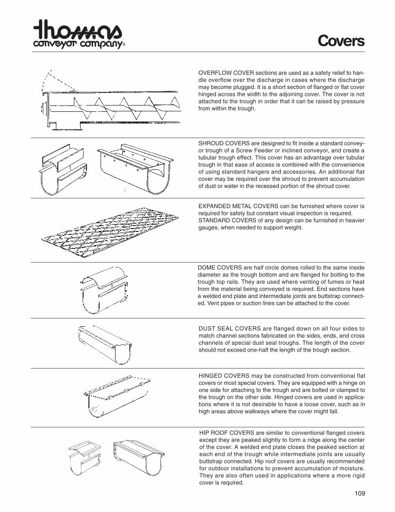
OVERFLOW COVER sections are used as a safety relief to han-dle overflow over the discharge in cases where the dischargemay become plugged. It is a short section of flanged or flat coverhinged across the width to the adjoining cover. The cover is notattached to the trough in order that it can be raised by pressurefrom within the trough.
SHROUD COVERS are designed to fit inside a standard convey-or trough of a Screw Feeder or inclined conveyor, and create atubular trough effect. This cover has an advantage over tubulartrough in that ease of access is combined with the convenienceof using standard hangers and accessories. An additional flatcover may be required over the shroud to prevent accumulationof dust or water in the recessed portion of the shroud cover.
EXPANDED METAL COVERS can be furnished where cover isrequired for safety but constant visual inspection is required.STANDARD COVERS of any design can be furnished in heaviergauges, when needed to support weight.
DOME COVERS are half circle domes rolled to the same insidediameter as the trough bottom and are flanged for bolting to thetrough top rails. They are used where venting of fumes or heatfrom the material being conveyed is required. End sections havea welded end plate and intermediate joints are buttstrap connect-ed. Vent pipes or suction lines can be attached to the cover.
DUST SEAL COVERS are flanged down on all four sides tomatch channel sections fabricated on the sides, ends, and crosschannels of special dust seal troughs. The length of the covershould not exceed one-half the length of the trough section.
HINGED COVERS may be constructed from conventional flatcovers or most special covers. They are equipped with a hinge onone side for attaching to the trough and are bolted or clamped tothe trough on the other side. Hinged covers are used in applica-tions where it is not desirable to have a loose cover, such as inhigh areas above walkways where the cover might fall.
HIP ROOF COVERS are similar to conventional flanged coversexcept they are peaked slightly to form a ridge along the centerof the cover. A welded end plate closes the peaked section ateach end of the trough while intermediate joints are usuallybuttstrap connected. Hip roof covers are usually recommendedfor outdoor installations to prevent accumulation of moisture.They are also often used in applications where a more rigidcover is required.
110
Trough Ends
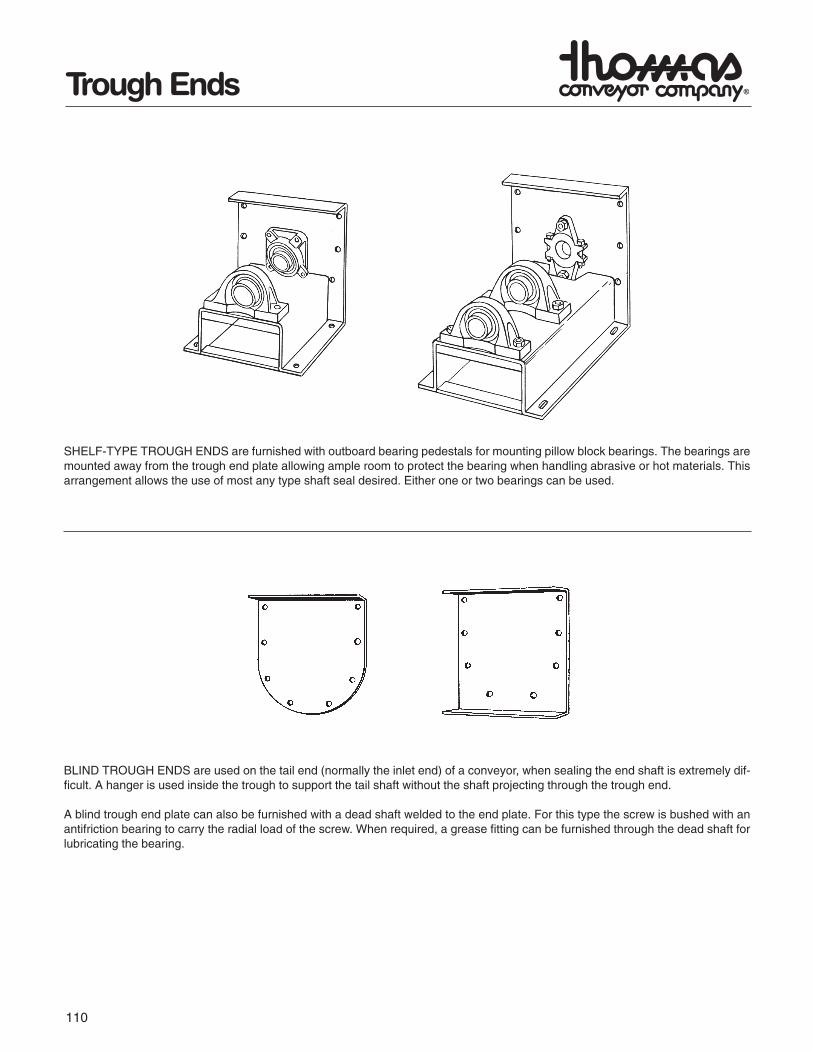
SHELF-TYPE TROUGH ENDS are furnished with outboard bearing pedestals for mounting pillow block bearings. The bearings aremounted away from the trough end plate allowing ample room to protect the bearing when handling abrasive or hot materials. Thisarrangement allows the use of most any type shaft seal desired. Either one or two bearings can be used.
BLIND TROUGH ENDS are used on the tail end (normally the inlet end) of a conveyor, when sealing the end shaft is extremely dif-ficult. A hanger is used inside the trough to support the tail shaft without the shaft projecting through the trough end.
A blind trough end plate can also be furnished with a dead shaft welded to the end plate. For this type the screw is bushed with anantifriction bearing to carry the radial load of the screw. When required, a grease fitting can be furnished through the dead shaft forlubricating the bearing.
111
Trough
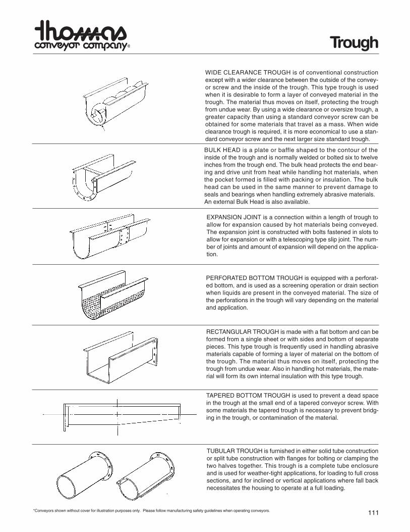
PERFORATED BOTTOM TROUGH is equipped with a perforat-ed bottom, and is used as a screening operation or drain sectionwhen liquids are present in the conveyed material. The size ofthe perforations in the trough will vary depending on the materialand application.
RECTANGULAR TROUGH is made with a flat bottom and can beformed from a single sheet or with sides and bottom of separatepieces. This type trough is frequently used in handling abrasivematerials capable of forming a layer of material on the bottom ofthe trough. The material thus moves on itself, protecting thetrough from undue wear. Also in handling hot materials, the mate-rial will form its own internal insulation with this type trough.
TAPERED BOTTOM TROUGH is used to prevent a dead spacein the trough at the small end of a tapered conveyor screw. Withsome materials the tapered trough is necessary to prevent bridg-ing in the trough, or contamination of the material.
TUBULAR TROUGH is furnished in either solid tube constructionor split tube construction with flanges for bolting or clamping thetwo halves together. This trough is a complete tube enclosureand is used for weather-tight applications, for loading to full crosssections, and for inclined or vertical applications where fall backnecessitates the housing to operate at a full loading.
WIDE CLEARANCE TROUGH is of conventional constructionexcept with a wider clearance between the outside of the convey-or screw and the inside of the trough. This type trough is usedwhen it is desirable to form a layer of conveyed material in thetrough. The material thus moves on itself, protecting the troughfrom undue wear. By using a wide clearance or oversize trough, agreater capacity than using a standard conveyor screw can beobtained for some materials that travel as a mass. When wideclearance trough is required, it is more economical to use a stan-dard conveyor screw and the next larger size standard trough.
BULK HEAD is a plate or baffle shaped to the contour of theinside of the trough and is normally welded or bolted six to twelveinches from the trough end. The bulk head protects the end bear-ing and drive unit from heat while handling hot materials, whenthe pocket formed is filled with packing or insulation. The bulkhead can be used in the same manner to prevent damage toseals and bearings when handling extremely abrasive materials.An external Bulk Head is also available.
EXPANSION JOINT is a connection within a length of trough toallow for expansion caused by hot materials being conveyed.The expansion joint is constructed with bolts fastened in slots toallow for expansion or with a telescoping type slip joint. The num-ber of joints and amount of expansion will depend on the applica-tion.
*Conveyors shown without cover for illustration purposes only. Please follow manufacturing safety guidelines when operating conveyors.
112
Trough
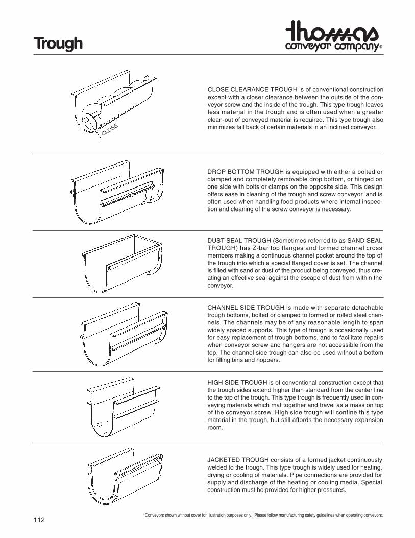
CLOSE CLEARANCE TROUGH is of conventional constructionexcept with a closer clearance between the outside of the con-veyor screw and the inside of the trough. This type trough leavesless material in the trough and is often used when a greaterclean-out of conveyed material is required. This type trough alsominimizes fall back of certain materials in an inclined conveyor.
DROP BOTTOM TROUGH is equipped with either a bolted orclamped and completely removable drop bottom, or hinged onone side with bolts or clamps on the opposite side. This designoffers ease in cleaning of the trough and screw conveyor, and isoften used when handling food products where internal inspec-tion and cleaning of the screw conveyor is necessary.
DUST SEAL TROUGH (Sometimes referred to as SAND SEALTROUGH) has Z-bar top flanges and formed channel crossmembers making a continuous channel pocket around the top ofthe trough into which a special flanged cover is set. The channelis filled with sand or dust of the product being conveyed, thus cre-ating an effective seal against the escape of dust from within theconveyor.
CLOSE
*Conveyors shown without cover for illustration purposes only. Please follow manufacturing safety guidelines when operating conveyors.
CHANNEL SIDE TROUGH is made with separate detachabletrough bottoms, bolted or clamped to formed or rolled steel chan-nels. The channels may be of any reasonable length to spanwidely spaced supports. This type of trough is occasionally usedfor easy replacement of trough bottoms, and to facilitate repairswhen conveyor screw and hangers are not accessible from thetop. The channel side trough can also be used without a bottomfor filling bins and hoppers.
HIGH SIDE TROUGH is of conventional construction except thatthe trough sides extend higher than standard from the center lineto the top of the trough. This type trough is frequently used in con-veying materials which mat together and travel as a mass on topof the conveyor screw. High side trough will confine this typematerial in the trough, but still affords the necessary expansionroom.
JACKETED TROUGH consists of a formed jacket continuouslywelded to the trough. This type trough is widely used for heating,drying or cooling of materials. Pipe connections are provided forsupply and discharge of the heating or cooling media. Specialconstruction must be provided for higher pressures.
113
Trough
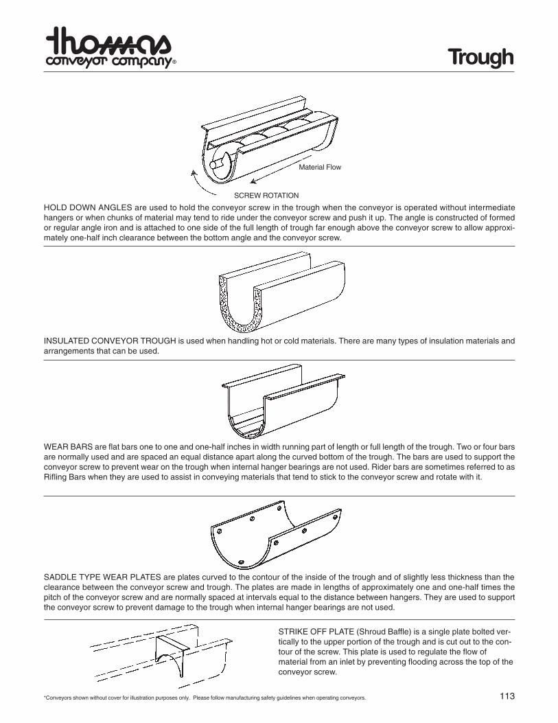
HOLD DOWN ANGLES are used to hold the conveyor screw in the trough when the conveyor is operated without intermediatehangers or when chunks of material may tend to ride under the conveyor screw and push it up. The angle is constructed of formedor regular angle iron and is attached to one side of the full length of trough far enough above the conveyor screw to allow approxi-mately one-half inch clearance between the bottom angle and the conveyor screw.
INSULATED CONVEYOR TROUGH is used when handling hot or cold materials. There are many types of insulation materials andarrangements that can be used.
WEAR BARS are flat bars one to one and one-half inches in width running part of length or full length of the trough. Two or four barsare normally used and are spaced an equal distance apart along the curved bottom of the trough. The bars are used to support theconveyor screw to prevent wear on the trough when internal hanger bearings are not used. Rider bars are sometimes referred to asRifling Bars when they are used to assist in conveying materials that tend to stick to the conveyor screw and rotate with it.
SADDLE TYPE WEAR PLATES are plates curved to the contour of the inside of the trough and of slightly less thickness than theclearance between the conveyor screw and trough. The plates are made in lengths of approximately one and one-half times thepitch of the conveyor screw and are normally spaced at intervals equal to the distance between hangers. They are used to supportthe conveyor screw to prevent damage to the trough when internal hanger bearings are not used.
SCREW ROTATION
*Conveyors shown without cover for illustration purposes only. Please follow manufacturing safety guidelines when operating conveyors.
STRIKE OFF PLATE (Shroud Baffle) is a single plate bolted ver-tically to the upper portion of the trough and is cut out to the con-tour of the screw. This plate is used to regulate the flow ofmaterial from an inlet by preventing flooding across the top of theconveyor screw.
Material Flow
114
Conveyor Screws
6 19 11⁄2
12 214 216 21⁄218 21⁄220 324 3
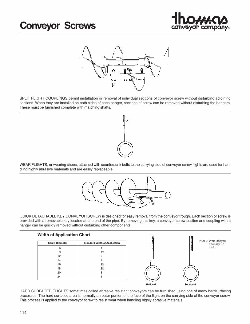
SPLIT FLIGHT COUPLINGS permit installation or removal of individual sections of conveyor screw without disturbing adjoiningsections. When they are installed on both sides of each hanger, sections of screw can be removed without disturbing the hangers.These must be furnished complete with matching shafts.
WEAR FLIGHTS, or wearing shoes, attached with countersunk bolts to the carrying side of conveyor screw flights are used for han-dling highly abrasive materials and are easily replaceable.
QUICK DETACHABLE KEY CONVEYOR SCREW is designed for easy removal from the conveyor trough. Each section of screw isprovided with a removable key located at one end of the pipe. By removing this key, a conveyor screw section and coupling with ahanger can be quickly removed without disturbing other components.
Screw Diameter Standard Width of Application
HARD SURFACED FLIGHTS sometimes called abrasive resistant conveyors can be furnished using one of many hardsurfacingprocesses. The hard surfaced area is normally an outer portion of the face of the flight on the carrying side of the conveyor screw.This process is applied to the conveyor screw to resist wear when handling highly abrasive materials.
NOTE: Weld-on typenormally 1⁄16″thick.
Helicoid Sectional
Width of Application Chart
115
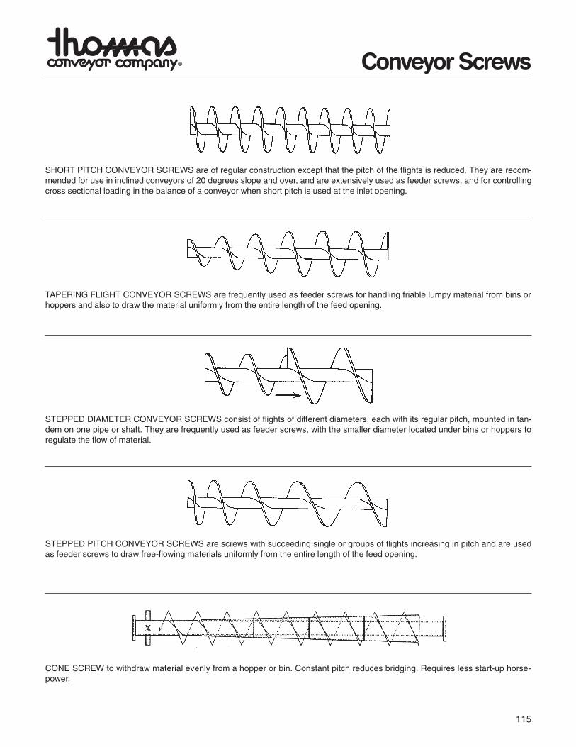
SHORT PITCH CONVEYOR SCREWS are of regular construction except that the pitch of the flights is reduced. They are recom-mended for use in inclined conveyors of 20 degrees slope and over, and are extensively used as feeder screws, and for controllingcross sectional loading in the balance of a conveyor when short pitch is used at the inlet opening.
TAPERING FLIGHT CONVEYOR SCREWS are frequently used as feeder screws for handling friable lumpy material from bins orhoppers and also to draw the material uniformly from the entire length of the feed opening.
STEPPED DIAMETER CONVEYOR SCREWS consist of flights of different diameters, each with its regular pitch, mounted in tan-dem on one pipe or shaft. They are frequently used as feeder screws, with the smaller diameter located under bins or hoppers toregulate the flow of material.
STEPPED PITCH CONVEYOR SCREWS are screws with succeeding single or groups of flights increasing in pitch and are usedas feeder screws to draw free-flowing materials uniformly from the entire length of the feed opening.
CONE SCREW to withdraw material evenly from a hopper or bin. Constant pitch reduces bridging. Requires less start-up horse-power.
Conveyor Screws
116
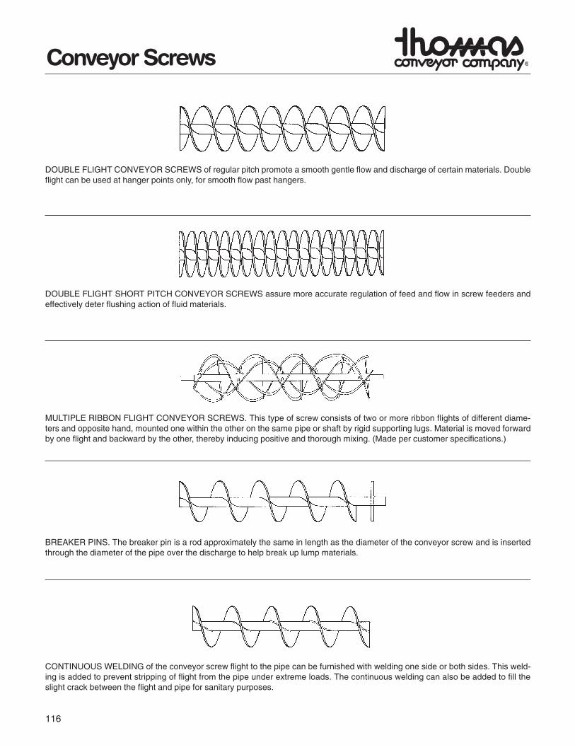
DOUBLE FLIGHT CONVEYOR SCREWS of regular pitch promote a smooth gentle flow and discharge of certain materials. Doubleflight can be used at hanger points only, for smooth flow past hangers.
DOUBLE FLIGHT SHORT PITCH CONVEYOR SCREWS assure more accurate regulation of feed and flow in screw feeders andeffectively deter flushing action of fluid materials.
MULTIPLE RIBBON FLIGHT CONVEYOR SCREWS. This type of screw consists of two or more ribbon flights of different diame-ters and opposite hand, mounted one within the other on the same pipe or shaft by rigid supporting lugs. Material is moved forwardby one flight and backward by the other, thereby inducing positive and thorough mixing. (Made per customer specifications.)
BREAKER PINS. The breaker pin is a rod approximately the same in length as the diameter of the conveyor screw and is insertedthrough the diameter of the pipe over the discharge to help break up lump materials.
CONTINUOUS WELDING of the conveyor screw flight to the pipe can be furnished with welding one side or both sides. This weld-ing is added to prevent stripping of flight from the pipe under extreme loads. The continuous welding can also be added to fill theslight crack between the flight and pipe for sanitary purposes.
Conveyor Screws
117
Conveyor Screws
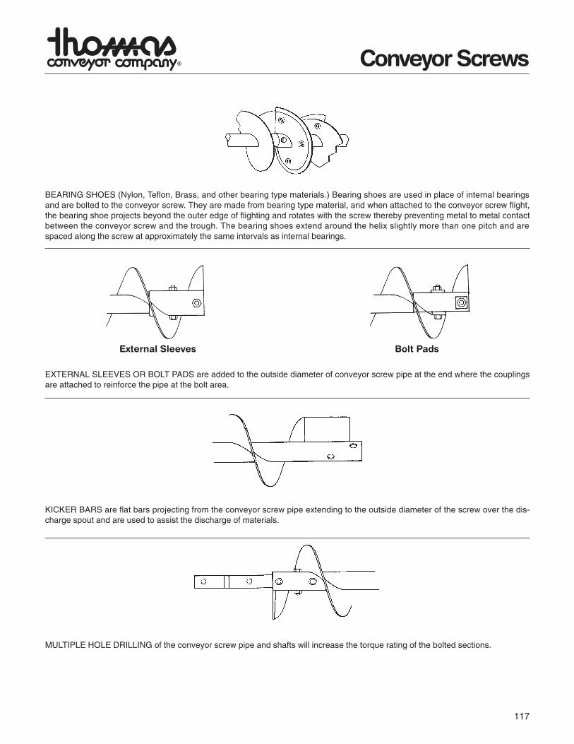
BEARING SHOES (Nylon, Teflon, Brass, and other bearing type materials.) Bearing shoes are used in place of internal bearingsand are bolted to the conveyor screw. They are made from bearing type material, and when attached to the conveyor screw flight,the bearing shoe projects beyond the outer edge of flighting and rotates with the screw thereby preventing metal to metal contactbetween the conveyor screw and the trough. The bearing shoes extend around the helix slightly more than one pitch and arespaced along the screw at approximately the same intervals as internal bearings.
EXTERNAL SLEEVES OR BOLT PADS are added to the outside diameter of conveyor screw pipe at the end where the couplingsare attached to reinforce the pipe at the bolt area.
KICKER BARS are flat bars projecting from the conveyor screw pipe extending to the outside diameter of the screw over the dis-charge spout and are used to assist the discharge of materials.
MULTIPLE HOLE DRILLING of the conveyor screw pipe and shafts will increase the torque rating of the bolted sections.
External Sleeves Bolt Pads
118
Conveyor Screws
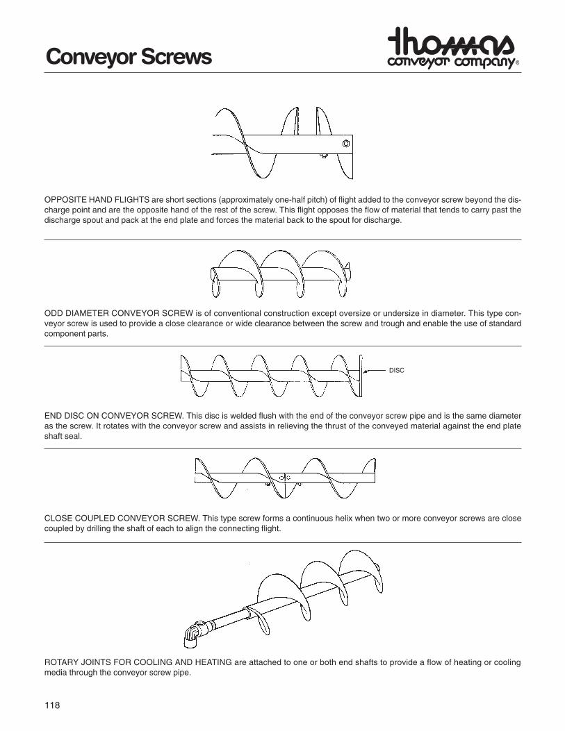
OPPOSITE HAND FLIGHTS are short sections (approximately one-half pitch) of flight added to the conveyor screw beyond the dis-charge point and are the opposite hand of the rest of the screw. This flight opposes the flow of material that tends to carry past thedischarge spout and pack at the end plate and forces the material back to the spout for discharge.
ODD DIAMETER CONVEYOR SCREW is of conventional construction except oversize or undersize in diameter. This type con-veyor screw is used to provide a close clearance or wide clearance between the screw and trough and enable the use of standardcomponent parts.
END DISC ON CONVEYOR SCREW. This disc is welded flush with the end of the conveyor screw pipe and is the same diameteras the screw. It rotates with the conveyor screw and assists in relieving the thrust of the conveyed material against the end plateshaft seal.
CLOSE COUPLED CONVEYOR SCREW. This type screw forms a continuous helix when two or more conveyor screws are closecoupled by drilling the shaft of each to align the connecting flight.
ROTARY JOINTS FOR COOLING AND HEATING are attached to one or both end shafts to provide a flow of heating or coolingmedia through the conveyor screw pipe.
DISC
119
Discharges
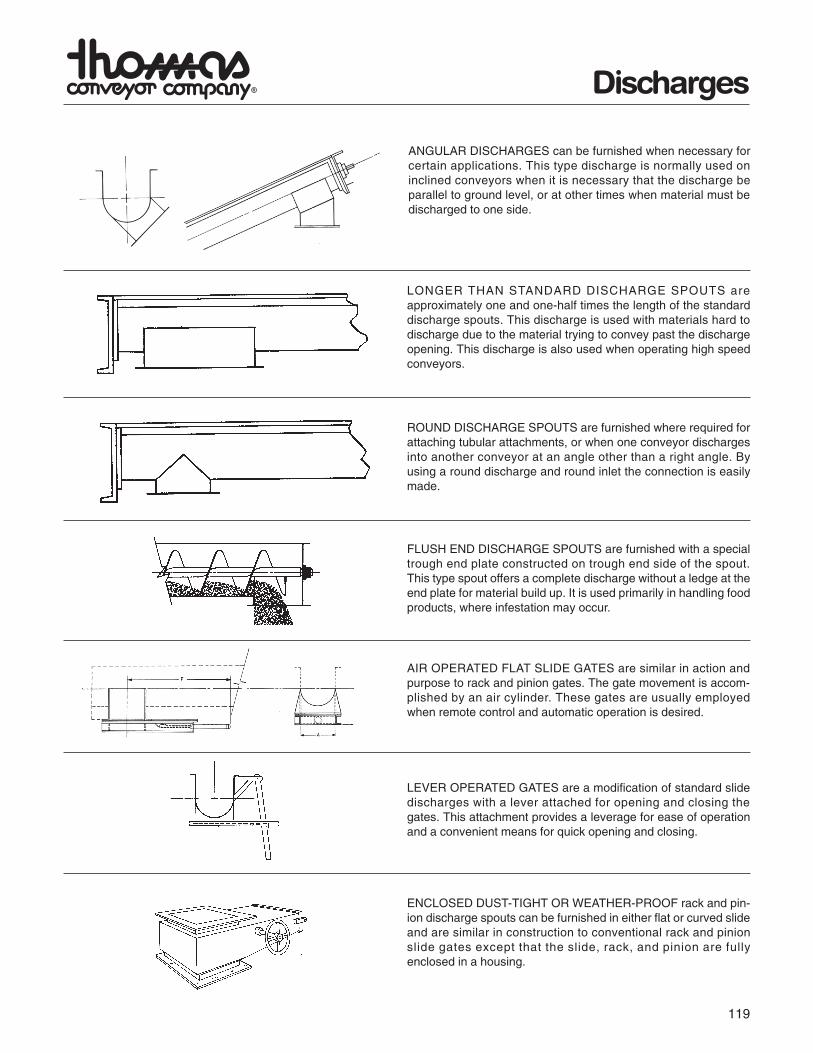
ANGULAR DISCHARGES can be furnished when necessary forcertain applications. This type discharge is normally used oninclined conveyors when it is necessary that the discharge beparallel to ground level, or at other times when material must bedischarged to one side.
LONGER THAN STANDARD DISCHARGE SPOUTS areapproximately one and one-half times the length of the standarddischarge spouts. This discharge is used with materials hard todischarge due to the material trying to convey past the dischargeopening. This discharge is also used when operating high speedconveyors.
ROUND DISCHARGE SPOUTS are furnished where required forattaching tubular attachments, or when one conveyor dischargesinto another conveyor at an angle other than a right angle. Byusing a round discharge and round inlet the connection is easilymade.
FLUSH END DISCHARGE SPOUTS are furnished with a specialtrough end plate constructed on trough end side of the spout.This type spout offers a complete discharge without a ledge at theend plate for material build up. It is used primarily in handling foodproducts, where infestation may occur.
AIR OPERATED FLAT SLIDE GATES are similar in action andpurpose to rack and pinion gates. The gate movement is accom-plished by an air cylinder. These gates are usually employedwhen remote control and automatic operation is desired.
LEVER OPERATED GATES are a modification of standard slidedischarges with a lever attached for opening and closing thegates. This attachment provides a leverage for ease of operationand a convenient means for quick opening and closing.
ENCLOSED DUST-TIGHT OR WEATHER-PROOF rack and pin-ion discharge spouts can be furnished in either flat or curved slideand are similar in construction to conventional rack and pinionslide gates except that the slide, rack, and pinion are fullyenclosed in a housing.
120
Dischargesand Inlets
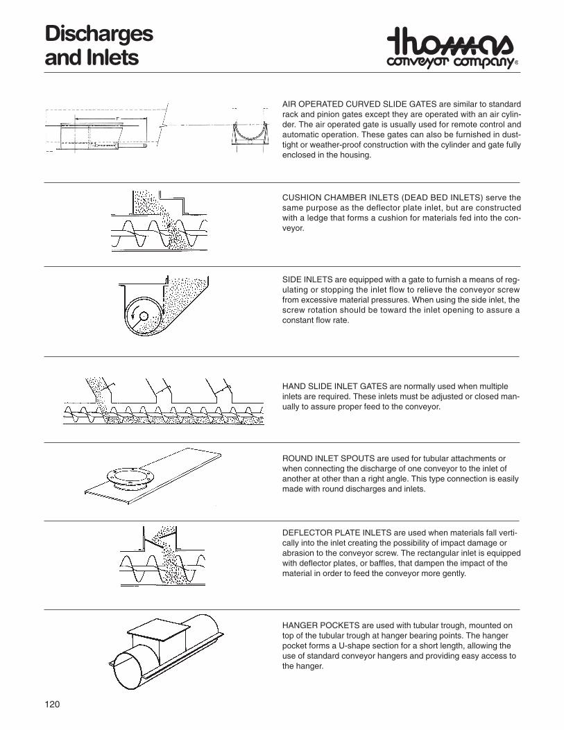
AIR OPERATED CURVED SLIDE GATES are similar to standardrack and pinion gates except they are operated with an air cylin-der. The air operated gate is usually used for remote control andautomatic operation. These gates can also be furnished in dust-tight or weather-proof construction with the cylinder and gate fullyenclosed in the housing.
CUSHION CHAMBER INLETS (DEAD BED INLETS) serve thesame purpose as the deflector plate inlet, but are constructedwith a ledge that forms a cushion for materials fed into the con-veyor.
SIDE INLETS are equipped with a gate to furnish a means of reg-ulating or stopping the inlet flow to relieve the conveyor screwfrom excessive material pressures. When using the side inlet, thescrew rotation should be toward the inlet opening to assure aconstant flow rate.
HAND SLIDE INLET GATES are normally used when multipleinlets are required. These inlets must be adjusted or closed man-ually to assure proper feed to the conveyor.
ROUND INLET SPOUTS are used for tubular attachments orwhen connecting the discharge of one conveyor to the inlet ofanother at other than a right angle. This type connection is easilymade with round discharges and inlets.
DEFLECTOR PLATE INLETS are used when materials fall verti-cally into the inlet creating the possibility of impact damage orabrasion to the conveyor screw. The rectangular inlet is equippedwith deflector plates, or baffles, that dampen the impact of thematerial in order to feed the conveyor more gently.
HANGER POCKETS are used with tubular trough, mounted ontop of the tubular trough at hanger bearing points. The hangerpocket forms a U-shape section for a short length, allowing theuse of standard conveyor hangers and providing easy access tothe hanger.