Embed Size (px)
Citation preview
TC 3
001
Three phase thyristor for resistive, inductive andtemperature dependent (complex) loads
CONTROLSDATA MANAGEMENT
PROCESS AUTOMATION
abc
TC 3001 Three phase thyristor unit for resistive, inductive and
temperature dependent (complex) loads The TC 3001 is a universal thyristor unit used to control a wide selection of three phaseloads. It operates with any load configuration for all types of electrical heating. Selfcontained units are available for currents up to 1000A, above this the control electronicsand power module are separate and extend the current capacity up to 1800A and beyond.
The TC 3001 provides precision control of direct and transformer connected heaters,variable temperature coefficient elements (e.g. platinum, tungsten, molybdenumdisilicide and silicon carbide), short-wave infrared lamps, induction and RF heating andimmersed electrodes for glass heating.
Safety - As with all Eurotherm products the TC 3001 has been designed to ensureoperator safety and load protection. When installed and used in compliance with usermanual HA174834 it meets the essential requirements of the EEC Low Voltage Directive.The self contained units are fully shrouded in an IP20 rated protective case withcommissioning and diagnostics points available on the front fascia. High speedsemiconductor fuses and other protection circuits are built in. Automatic alarm shutdownprotects the load and supply by quenching the thyristors if the unit detects an abnormalevent.
CE mark- The TC3001 is CE marked to show compliance with the essential protectionrequirements of the Low Voltage Directive. It is designed so that it can be used as part ofa CE compliant system but it is the responsibility of the installer to establish the CEcompliance of the overall system. The TC3001 technical construction file is approved by aCompetent Body (LCIE France). A Declaration of Compliance with the EuropeanDirectives is available on request.
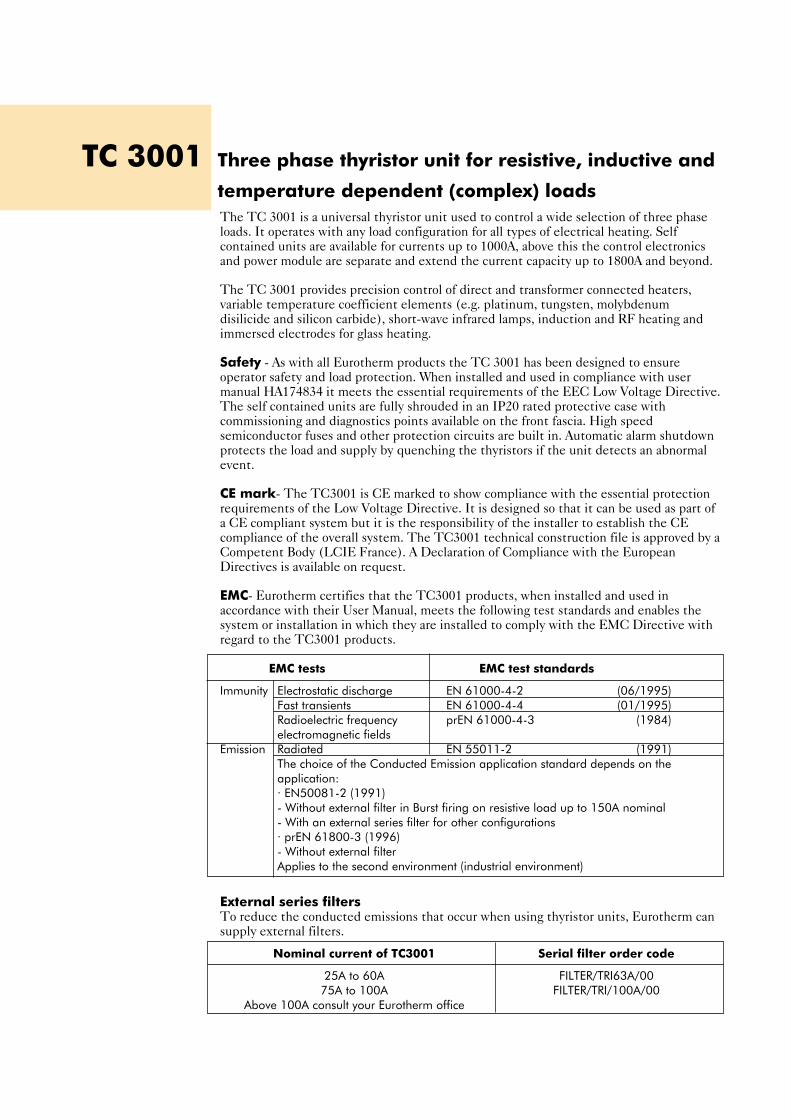
EMC- Eurotherm certifies that the TC3001 products, when installed and used inaccordance with their User Manual, meets the following test standards and enables thesystem or installation in which they are installed to comply with the EMC Directive withregard to the TC3001 products.
EMC tests EMC test standards
Immunity Electrostatic discharge EN 61000-4-2 (06/1995)Fast transients EN 61000-4-4 (01/1995)Radioelectric frequency prEN 61000-4-3 (1984)electromagnetic fields
Emission Radiated EN 55011-2 (1991)The choice of the Conducted Emission application standard depends on the application:· EN50081-2 (1991)- Without external filter in Burst firing on resistive load up to 150A nominal- With an external series filter for other configurations· prEN 61800-3 (1996)- Without external filterApplies to the second environment (industrial environment)
External series filtersTo reduce the conducted emissions that occur when using thyristor units, Eurotherm cansupply external filters.
Nominal current of TC3001 Serial filter order code
25A to 60A FILTER/TRI63A/0075A to 100A FILTER/TRI/100A/00
Above 100A consult your Eurotherm office

L1L2L3
Isolation and line protection
LINE
TC 3001
LOAD LOAD
Thyristor protection
fuses
3 wire star connection 4 wire star connection
L1L2L3
Isolation and line protection
LINE
TC 3001
LOAD LOAD
Thyristor protection
fuses
L1L2L3N
Isolation and line protection
LINE
TC 3001
LOAD LOAD
M(N)
Thyristor protection
fuses
71
Neutralconnection(reference)
3 wire delta connection 6 wire delta connection (open delta)
L1L2L3
Isolation and line protection
LINE
TC 3001
LOAD LOAD
Thyristor protection
fuses
Easy to connect to any load - The diagrams show how the TC 3001 can be used with
any three phase load (three wire star or delta, four wire star with neutral and six wire open
delta). The TC 3001 is insensitive to phase rotation so the phases can be connected in any
order. The unit also synchronises itself to the supply frequency, further easing installation.
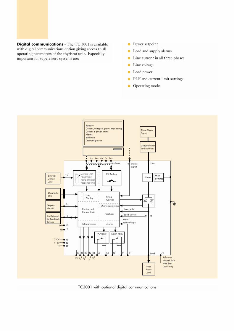
Power setpoint
Load and supply alarms
Line current in all three phases
Line voltage
Load power
PLF and current limit settings
Operating mode
Digital communications - The TC 3001 is available
with digital communications option giving access to all
operating parameters of the thyristor unit. Especially
important for supervisory systems are:
UserDisplay
Control and Current Limit
Retransmission
FiringControl
Overtemp sensing
Feedback
Alarms
ExternalCurrentLimit
Setpoint(Input)
2nd SetpointExt FeedbackRetrans
Current limitPower limitRamp durationResponse time
PLF Setting
Optional digital communications
SetpointCurrent, voltage & power monitoringCurrent & power limitsAlarmsInhibitionOperating mode
Fuses
Line protection and isolation
Three Phase Supply
Enable Signal
Micro-switches
Load volts
Load current
Three PhaseLoad
DiagnosticUnit
AlarmAcknowledge
PLF Relay Alarm Relay
52 51 62 61 11
13
14
12
170V
05 04 03 02 01
0V I12 I2
2 I32 V2
15
Rx- Rx+ OV Tx- Tx+
230V
115VN
Line
Load
1610V
43
4241
71
Reference Neutral for 4 Wire Star Loads only
TC3001 with optional digital communications
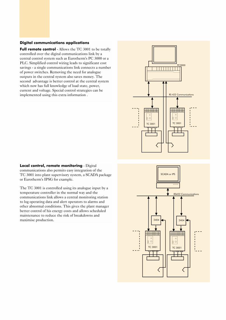
Digital communications applications
Full remote control - Allows the TC 3001 to be totally
controlled over the digital communications link by a
central control system such as Eurotherm's PC 3000 or a
PLC. Simplified control wiring leads to significant cost
savings - a single communications link connects a number
of power switches. Removing the need for analogue
outputs in the central system also saves money. The
second advantage is better control at the central system
which now has full knowledge of load state, power,
current and voltage. Special control strategies can be
implemented using this extra information .
2404
TC 3001
SCADA or IPS
TC 3001
RS422 Communications
2404
PC3000
TC 3001TC 3001
RS 422 Communications
Local control, remote monitoring - Digital
communications also permits easy integration of the
TC 3001 into plant supervisory system, a SCADA package
or Eurotherm's IPSG for example.
The TC 3001 is controlled using its analogue input by a
temperature controller in the normal way and the
communications link allows a central monitoring station
to log operating data and alert operators to alarms and
other abnormal conditions. This gives the plant manager
better control of his energy costs and allows scheduled
maintenance to reduce the risk of breakdowns and
maximise production.
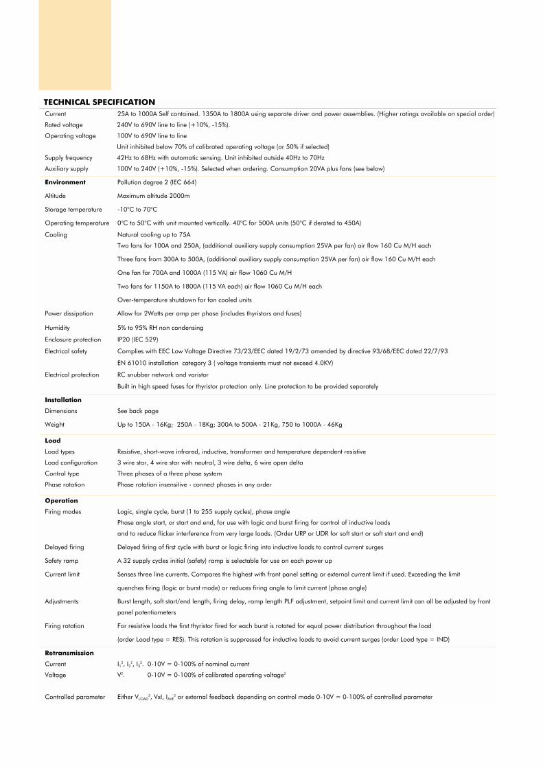
TECHNICAL SPECIFICATION Current 25A to 1000A Self contained. 1350A to 1800A using separate driver and power assemblies. (Higher ratings available on special order)
Rated voltage 240V to 690V line to line (+10%, -15%).
Operating voltage 100V to 690V line to line
Unit inhibited below 70% of calibrated operating voltage (or 50% if selected)
Supply frequency 42Hz to 68Hz with automatic sensing. Unit inhibited outside 40Hz to 70Hz
Auxiliary supply 100V to 240V (+10%, -15%). Selected when ordering. Consumption 20VA plus fans (see below)
Environment Pollution degree 2 (IEC 664)
Altitude Maximum altitude 2000m
Storage temperature -10°C to 70°C
Operating temperature 0°C to 50°C with unit mounted vertically. 40°C for 500A units (50°C if derated to 450A)
Cooling Natural cooling up to 75A
Two fans for 100A and 250A, (additional auxiliary supply consumption 25VA per fan) air flow 160 Cu M/H each
Three fans from 300A to 500A, (additional auxiliary supply consumption 25VA per fan) air flow 160 Cu M/H each
One fan for 700A and 1000A (115 VA) air flow 1060 Cu M/H
Two fans for 1150A to 1800A (115 VA each) air flow 1060 Cu M/H each
Over-temperature shutdown for fan cooled units
Power dissipation Allow for 2Watts per amp per phase (includes thyristors and fuses)
Humidity 5% to 95% RH non condensing
Enclosure protection IP20 (IEC 529)
Electrical safety Complies with EEC Low Voltage Directive 73/23/EEC dated 19/2/73 amended by directive 93/68/EEC dated 22/7/93
EN 61010 installation category 3 ( voltage transients must not exceed 4.0KV)
Electrical protection RC snubber network and varistor
Built in high speed fuses for thyristor protection only. Line protection to be provided separately
Installation
Dimensions See back page
Weight Up to 150A - 16Kg; 250A - 18Kg; 300A to 500A - 21Kg, 750 to 1000A - 46Kg
Load
Load types Resistive, short-wave infrared, inductive, transformer and temperature dependent resistive
Load configuration 3 wire star, 4 wire star with neutral, 3 wire delta, 6 wire open delta
Control type Three phases of a three phase system
Phase rotation Phase rotation insensitive - connect phases in any order
Operation
Firing modes Logic, single cycle, burst (1 to 255 supply cycles), phase angle
Phase angle start, or start and end, for use with logic and burst firing for control of inductive loads
and to reduce flicker interference from very large loads. (Order URP or UDR for soft start or soft start and end)
Delayed firing Delayed firing of first cycle with burst or logic firing into inductive loads to control current surges
Safety ramp A 32 supply cycles initial (safety) ramp is selectable for use on each power up
Current limit Senses three line currents. Compares the highest with front panel setting or external current limit if used. Exceeding the limit
quenches firing (logic or burst mode) or reduces firing angle to limit current (phase angle)
Adjustments Burst length, soft start/end length, firing delay, ramp length PLF adjustment, setpoint limit and current limit can all be adjusted by front
panel potentiometers
Firing rotation For resistive loads the first thyristor fired for each burst is rotated for equal power distribution throughout the load
(order Load type = RES). This rotation is suppressed for inductive loads to avoid current surges (order Load type = IND)
Retransmission
Current I12, I22, I32. 0-10V = 0-100% of nominal current
Voltage V2. 0-10V = 0-100% of calibrated operating voltage2
Controlled parameter Either VLOAD2, VxI, IAVE
2 or external feedback depending on control mode 0-10V = 0-100% of controlled parameter

Control
Analogue input Voltage: 0-5V, 1-5V, 0-10V, 2-10V. Input impedance > 100kΩ
Current: 0-20mA, 4-20mA. Input impedance = 100Ω
Second input Same input ranges, minimum of two inputs wins (only without digital communications)
Logic input Range selected from analogue input. >50% =ON, <25%=OFF
Control modes V2
Normal mode to eliminate power variations caused by supply fluctuations
(feedback) V x I True power control for use without closed loop temperature control or for specialist applications
I2
Usually used for direct electric heating of glass under special circumstances
External input Controls an externally measured parameter (e.g. direct voltage or current after rectification)
I2to V
2transfer For best temperature control of variable resistance elements over large temperature ranges
(only with digital communications)
Setpoint limit Proportional scaling of setpoint signal by front fascia potentiometer (P3)
Feedback linearity Phase angle ±1% , Burst firing ±2% for all feedback modes
Stability Phase angle ±1% , Burst firing ±2% for +10% to -15% supply variation, for 0°C to 50°C ambient temperature and for load impedance
changes of ±30% (for V x I or I2control)
Alarms
Inhibition alarms Loss of one phase of the supply
Under voltage (70% or 50% of calibrated operating voltage depending on configuration)
Frequency outside 40 to 70Hz limits
Over current (logic or burst firing)
Thyristor short circuit (Note with short circuit thyristors, current can continue to flow)
Indicating alarms Over voltage (indication 20% above calibrated operating voltage)
Partial load failure (PLF). Detection one in four to one in eight parallel identical elements per limb of the three phase load.
(PLF sensitivity depends on load configuration and only works above 10% of nominal current)
Load unbalance
Alarm indication Front fascia display, two relays and optional digital communications
Alarm acknowledge External contact to acknowledge alarms and resume normal operation
Digital communications (optional)
Physical link RS422 (4 wire) or RS485 (2 or 4 wire)
Protocol EUROTHERM, MODBUS® or JBUS® also PROFIBUS (consult Eurotherm)
Baud rate 9600 or 19200 baud
Options Communications module also has additional analogue and digital I/O
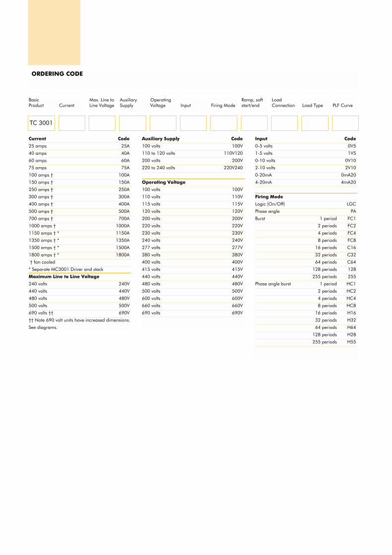
ORDERING CODE
TC 3001
BasicProduct Current
Max. Line toLine Voltage
AuxiliarySupply
OperatingVoltage Input Firing Mode
Ramp, softstart/end
LoadConnection Load Type PLF Curve
Current Code
25 amps 25A
40 amps 40A
60 amps 60A
75 amps 75A
100 amps † 100A
150 amps † 150A
250 amps † 250A
300 amps † 300A
400 amps † 400A
500 amps † 500A
700 amps † 700A
1000 amps † 1000A
1150 amps † * 1150A
1350 amps † * 1350A
1500 amps † * 1500A
1800 amps † * 1800A
† fan cooled
* Separate MC3001 Driver and stack
Maximum Line to Line Voltage
240 volts 240V
440 volts 440V
480 volts 480V
500 volts 500V
690 volts †† 690V
†† Note 690 volt units have increased dimensions.
See diagrams.
Auxiliary Supply Code
100 volts 100V
110 to 120 volts 110V120
200 volts 200V
220 to 240 volts 220V240
Operating Voltage
100 volts 100V
110 volts 110V
115 volts 115V
120 volts 120V
200 volts 200V
220 volts 220V
230 volts 230V
240 volts 240V
277 volts 277V
380 volts 380V
400 volts 400V
415 volts 415V
440 volts 440V
480 volts 480V
500 volts 500V
600 volts 600V
660 volts 660V
690 volts 690V
Input Code
0-5 volts 0V5
1-5 volts 1V5
0-10 volts 0V10
2-10 volts 2V10
0-20mA 0mA20
4-20mA 4mA20
Firing Mode
Logic (On/Off) LGC
Phase angle PA
Burst 1 period FC1
2 periods FC2
4 periods FC4
8 periods FC8
16 periods C16
32 periods C32
64 periods C64
128 periods 128
255 periods 255
Phase angle burst 1 period HC1
2 periods HC2
4 periods HC4
8 periods HC8
16 periods H16
32 periods H32
64 periods H64
128 periods H28
255 periods H55

ControlMode
CurrentLimit
Inputs andOutputs PLU Alarm
ManualLanguage
CommsMode
CommsProtocol Fuses Options
Ramp, soft start/end Code
No ramp NRP
Soft start of burst URP
Soft start and end of burst UDR
Load Connection
3 Wire delta 3D
3 Wire star 3S
4 Wire star with neutral 4S
6 Wire open delta 6D
Load Type
Transformer IND
Other loads RES
Partial Load Failure (PLF curve)
Standard curve SD
Short-wave infrared curve †† IR
Control Mode (feedback)
V2 V2
I2 I2
Power W
I2/V2 transfer †† TR
External (see inputs and outputs) EX
Current Limit Code
Limit threshold for phase angle, phase angle
burst and burst with URP or UDR firing modes
Digital communications †† LCOM
Potentiometer on front fascia LINT
External signal 0-5V L0V5
1-5V LIV5
0-10V L0V10
2-10V L2V10
0-20mA L0mA20
4-20mA L4mA20
Chop off for logic, and burst firing (without URP
or UDR)
Digital communications †† COM
Potentiometer on front fascia CINT
External signal 0-5V C0V5
1-5V CIV5
0-10V C0V10
2-10V C2V10
0-20mA C0mA20
4-20mA C4mA20
Inputs and Outputs **
0-10V controlled parameter retransmission RTR
0-10V external feedback (if “EX” selected) E0VI0
0-10V second setpoint W0VI0
PLU Alarm Code
Detection disabled 000
Open in alarm PLU
Closed in alarm IPU
Manual language
English ENG
French FRA
German GER
Communications Mode/Speed
No comms 000
Read only at 9600 bauds R96
19200 bauds R192
Profibus read only RAUT
Read and write at 9600 bauds W96
19200 bauds W192
Profibus read and write WAUT
Communications Protocol
EUROTHERM EIP
JBUS® JBP
MODBUS® MOP
PROFIBUS PFP
Fuses
Internal fuses FUSES
Fuses with microswitch FUMS
No fuse NOFUSE
Options
PLF closed in alarm (normally open in alarm) IPF
†† Only available with digital communications* Fan cooled** Other specialist options available. Contact
Eurotherm Controls for details.
SPARE FUSESUnit Current Fuse Part No.
25A LA172468U050
40A LA172468U080
60A LA172468U080
75A LA172468U100
100A LA172468U125
150A LA172468U200
250A LA172468U315
300A LA172468U400
400A LA172468U500
500A LA172468U630
700A CS175633U900
1000A CS175633U1250
Please note that replacement fuses are marked
with a higher current rating than the thyristors. This
allows correct operation up to 50°C and does not
imply that higher current is permissible.
EXTRASCode
Diagnostic unit (240V) 260-13-00
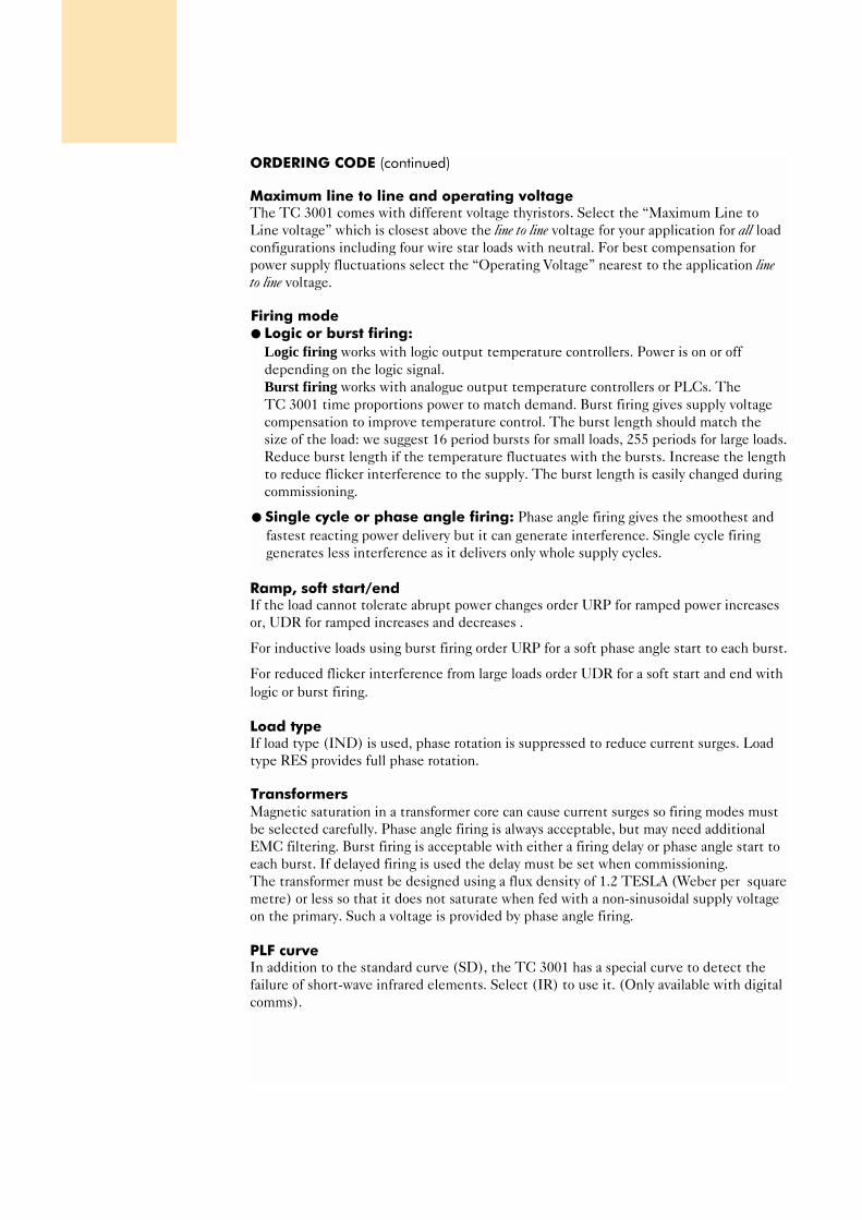
ORDERING CODE (continued)
Maximum line to line and operating voltageThe TC 3001 comes with different voltage thyristors. Select the “Maximum Line to
Line voltage” which is closest above the line to line voltage for your application for all load
configurations including four wire star loads with neutral. For best compensation for
power supply fluctuations select the “Operating Voltage” nearest to the application lineto line voltage.
Firing mode Logic or burst firing:
Logic firing works with logic output temperature controllers. Power is on or off
depending on the logic signal.
Burst firing works with analogue output temperature controllers or PLCs. The
TC 3001 time proportions power to match demand. Burst firing gives supply voltage
compensation to improve temperature control. The burst length should match the
size of the load: we suggest 16 period bursts for small loads, 255 periods for large loads.
Reduce burst length if the temperature fluctuates with the bursts. Increase the length
to reduce flicker interference to the supply. The burst length is easily changed during
commissioning.
Single cycle or phase angle firing: Phase angle firing gives the smoothest and
fastest reacting power delivery but it can generate interference. Single cycle firing
generates less interference as it delivers only whole supply cycles.
Ramp, soft start/endIf the load cannot tolerate abrupt power changes order URP for ramped power increases
or, UDR for ramped increases and decreases .
For inductive loads using burst firing order URP for a soft phase angle start to each burst.
For reduced flicker interference from large loads order UDR for a soft start and end with
logic or burst firing.
Load typeIf load type (IND) is used, phase rotation is suppressed to reduce current surges. Load
type RES provides full phase rotation.
TransformersMagnetic saturation in a transformer core can cause current surges so firing modes must
be selected carefully. Phase angle firing is always acceptable, but may need additional
EMC filtering. Burst firing is acceptable with either a firing delay or phase angle start to
each burst. If delayed firing is used the delay must be set when commissioning.
The transformer must be designed using a flux density of 1.2 TESLA (Weber per square
metre) or less so that it does not saturate when fed with a non-sinusoidal supply voltage
on the primary. Such a voltage is provided by phase angle firing.
PLF curveIn addition to the standard curve (SD), the TC 3001 has a special curve to detect the
failure of short-wave infrared elements. Select (IR) to use it. (Only available with digital
comms).
Control modeOption V2 gives compensation for supply variations and is suitable for most applications.
Current, power and external control modes are available. Please consult Eurotherm for
more information on these alternatives.
Current limitThe TC 3001 senses load current and compares it with a preset limit. For logic and burst
firing the TC 3001 is quenched if the limit is exceeded. For phase angle firing the firing
angle is reduced to limit the current. The limit is set by front fascia potentiometer,
external input or optional digital communications.
Inputs and outputsFor simplicity only the code for 0-10V retransmission or second setpoint are shown, other
ranges are available.
PLU (partial load unbalance) enableIf your load is unbalanced (25% difference between line currents) then select 'PLU
Detection Disabled' to avoid nuisance alarms.
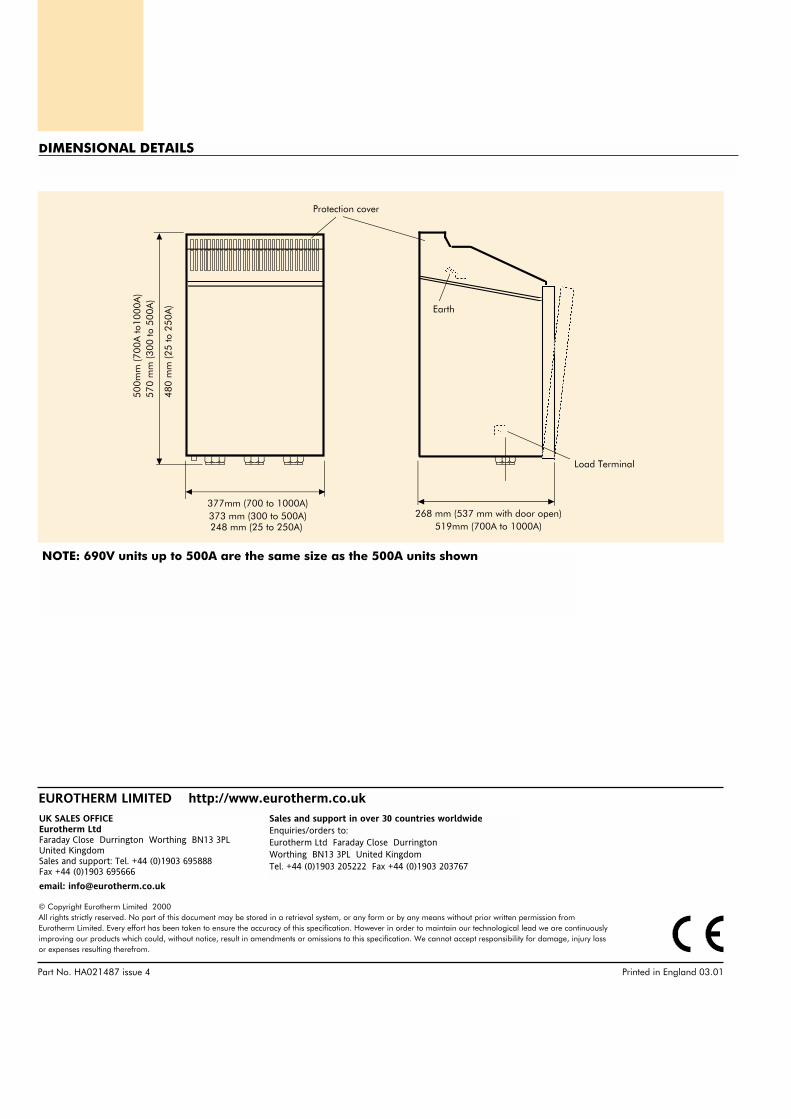
248 mm (25 to 250A)
377mm (700 to 1000A)373 mm (300 to 500A) 268 mm (537 mm with door open)
519mm (700A to 1000A)
500m
m (7
00A
to10
00A
)57
0 m
m (3
00 to
500
A)
480
mm
(25
to 2
50A
)
Protection cover
AAAAAAAAAA
Earth
AAAA
AAAAAAAAAAAAAAAA
AAAAAAAAAAAAAAAAAAA
Load Terminal
DIMENSIONAL DETAILS
NOTE: 690V units up to 500A are the same size as the 500A units shown
Part No. HA021487 issue 4 Printed in England 03.01
© Copyright Eurotherm Limited 2000All rights strictly reserved. No part of this document may be stored in a retrieval system, or any form or by any means without prior written permission fromEurotherm Limited. Every effort has been taken to ensure the accuracy of this specification. However in order to maintain our technological lead we are continuouslyimproving our products which could, without notice, result in amendments or omissions to this specification. We cannot accept responsibility for damage, injury lossor expenses resulting therefrom.
EUROTHERM LIMITED http://www.eurotherm.co.uk
Sales and support in over 30 countries worldwideEnquiries/orders to:Eurotherm Ltd Faraday Close Durrington Worthing BN13 3PL United KingdomTel. +44 (0)1903 205222 Fax +44 (0)1903 203767
UK SALES OFFICEEurotherm LtdFaraday Close Durrington Worthing BN13 3PLUnited KingdomSales and support: Tel. +44 (0)1903 695888 Fax +44 (0)1903 695666
email: [email protected]