Embed Size (px)
Citation preview

OPERATING INSTRUCTIONS
Language version: EN
Edition: 2012-02
Order number: 5780210593
From vehicle ID No.: TC00290815>
Original operating instructions
tc29
Crawler Excavator tc29
Cra
wle
r Exc
avat
or

Terex Deutschland GmbH Geschäftsbereich Compact Kraftwerkstrasse 4 74564 Crailsheim Germany Phone +49 (0) 7951 9357-0 Fax +49 (0) 7951 9357-671 E-Mail: [email protected] www.terexconstruction.com
Please complete before commissioning the crawler excavator:
Vehicle model: ..........................................................................
Vehicle ID No.: ..........................................................................
Year of construction: ...............................................................
Commissioned on: ...................................................................
Dealer: .......................................................................................
This operating manual is protected by limited copyright. It may be reproduced for and used by the drive / plant operator.

Table of Contents
TC29
1 Introduction ...................................................................................................................................1 1.1 Warranty and Maintenance.......................................................................................................................2 1.2 Copyright...................................................................................................................................................2 1.3 Notes on using the instruction book..........................................................................................................2 1.4 Environmental requirements .....................................................................................................................3 1.5 Pictograms ................................................................................................................................................3
2 Safety and Prevention of Accidents............................................................................................5 2.1 Introductory remarks .................................................................................................................................5 2.2 Proper use.................................................................................................................................................6 2.3 General safety notes.................................................................................................................................7 2.4 Operation ..................................................................................................................................................7 2.5 Danger zone..............................................................................................................................................8 2.6 Transport of persons.................................................................................................................................8 2.7 Stability......................................................................................................................................................8 2.8 Travel operation ........................................................................................................................................9 2.9 Operation ..................................................................................................................................................9 2.10 Guides...................................................................................................................................................10 2.11 Danger of falling objects .......................................................................................................................10 2.12 Working in the vicinity of underground power lines ..............................................................................10 2.13 Working in the vicinity of overhead power lines....................................................................................11 2.14 Operation in closed rooms ....................................................................................................................11 2.15 Work stoppages ....................................................................................................................................11 2.16 Load hook applications .........................................................................................................................12 2.17 Change of work attachments, maintenance, repair ..............................................................................12 2.18 Recovery, loading, transportation .........................................................................................................13 2.19 Monitoring and inspections ...................................................................................................................14 2.20 Fire protection .......................................................................................................................................14 2.21 Emergency exit .....................................................................................................................................14 2.22 Other dangers .......................................................................................................................................14
3 Technical data .............................................................................................................................15 3.1 Views.......................................................................................................................................................15 3.2 Engine .....................................................................................................................................................18 3.3 Electrical system .....................................................................................................................................18 3.4 Crawler-type undercarriage ....................................................................................................................18 3.5 Steering...................................................................................................................................................19 3.6 Brakes .....................................................................................................................................................19 3.7 Hydraulic system.....................................................................................................................................19 3.8 Lubricants................................................................................................................................................20
3.8.1 Filling quantities................................................................................................................................20 3.8.2 Fuel, lubricant and coolant specifications ........................................................................................21
3.9 Specific ground pressure ........................................................................................................................22 3.10 Sound level values, vibration ................................................................................................................22 3.11 Dimensions and weights .......................................................................................................................23 3.12 Carrying capacity ..................................................................................................................................24 3.13 Working range for grab operations .......................................................................................................25 3.14 Work attachments .................................................................................................................................26 3.15 Optional equipment...............................................................................................................................27
4 Operation .....................................................................................................................................29 4.1 First commissioning ................................................................................................................................29 4.2 Engine .....................................................................................................................................................32
4.2.1 Starting the engine ...........................................................................................................................32 4.2.2 Monitoring during operation..............................................................................................................33 4.2.3 Switching off the engine ...................................................................................................................33
4.3 Driver's seat ............................................................................................................................................34 4.4 Heating / Ventilation................................................................................................................................34 4.5 Front window...........................................................................................................................................35 4.6 Tracking and steering..............................................................................................................................36 4.7 Rubber crawler chains ............................................................................................................................37 4.8 Parking the machine ...............................................................................................................................38

Table of Contents
TC29
5 Working Operation of the Machine ...........................................................................................39 5.1 General ...................................................................................................................................................39 5.2 Operation – work function .......................................................................................................................40
5.2.1 Operation - working equipment ........................................................................................................40 5.2.2 Operation - articulation .....................................................................................................................41 5.2.3 Operation – dozer blade...................................................................................................................41 5.2.4 Operation – additional control circuit ................................................................................................42
5.3 Changing work attachments ...................................................................................................................43 5.3.1 General.............................................................................................................................................43 5.3.2 Assembly of work attachments.........................................................................................................44 5.3.3 -- .......................................................................................................................................................46 5.3.4 Clamshell grab..................................................................................................................................46 5.3.5 Hydraulic rock breaker .....................................................................................................................47
5.4 Dismounting the cab ...............................................................................................................................48 6 Recovery and Transport of the Machine ..................................................................................49
6.1 Recovery of the machine ........................................................................................................................49 6.2 Loading the machine by use of a crane..................................................................................................49 6.3 Transport of the machine ........................................................................................................................50
7 Care and Maintenance................................................................................................................51 7.1 General notes..........................................................................................................................................51 7.2 Intervals...................................................................................................................................................51 7.3 Regular oil analyses................................................................................................................................52 7.4 Warranty..................................................................................................................................................52 7.5 Inspection parts and aids ........................................................................................................................53 7.6 Care and cleaning...................................................................................................................................54 7.7 Notes for winter operation.......................................................................................................................54 7.8 Checking, maintenance and inspection plans ........................................................................................55
7.8.1 Initial inspection (delivery/ handing-over inspection)........................................................................55 7.8.2 Daily and weekly tasks .....................................................................................................................56 7.8.3 Overview of lubricating points ..........................................................................................................58 7.8.4 Inspection plan .................................................................................................................................60
7.9 Inspection and maintenance work ..........................................................................................................62 7.9.1 Engine oil..........................................................................................................................................62 7.9.2 Engine oil filter ..................................................................................................................................63 7.9.3 Engine - Cooling system ..................................................................................................................63 7.9.4 Fuel tank...........................................................................................................................................65 7.9.5 Air filter, air intake.............................................................................................................................67 7.9.6 V-belts ..............................................................................................................................................69 7.9.7 Valve lash .........................................................................................................................................71 7.9.8 Hydraulic oil tank ..............................................................................................................................72 7.9.9 Hydraulic oil cooler ...........................................................................................................................73 7.9.10 Hydraulic oil return filter..................................................................................................................74 7.9.11 Breather..........................................................................................................................................74 7.9.12 Crawler gear units ..........................................................................................................................75 7.9.13 Brake valves ...................................................................................................................................75 7.9.14 Crawler chains................................................................................................................................76 7.9.15 Swing bearing.................................................................................................................................77 7.9.16 Swing gear......................................................................................................................................78 7.9.17 Windshield washer .........................................................................................................................78 7.9.18 Electrical equipment .......................................................................................................................79
7.10 Shutdown ..............................................................................................................................................80 7.10.1 Preservation (temporary shutdown) ...............................................................................................80 7.10.2 During shutdown ............................................................................................................................80 7.10.3 After shutdown................................................................................................................................80

Table of Contents
TC29
8 Operating problems....................................................................................................................81 8.1 General ...................................................................................................................................................81 8.2 Engine .....................................................................................................................................................81 8.3 Machine is not driving .............................................................................................................................81 8.4 Insufficient travel power ..........................................................................................................................81 8.5 Excavator installation is not working.......................................................................................................82 8.6 Decrease in machine’s performance ......................................................................................................82 8.7 Machine is working too slowly and hydraulic oil is becoming too hot .....................................................82 8.8 Uppercarriage is slewing too far .............................................................................................................82 8.9 Working cylinders are not working satisfactorily .....................................................................................83 8.10 Trouble in the electrical system ............................................................................................................83
9 Appendix......................................................................................................................................85 9.1 Electrical system .....................................................................................................................................85 9.2 Immobilizer..............................................................................................................................................86

Table of Contents
TC29

Introduction 1
TC29 1
1 Introduction You decided to buy a Terex TC29 Crawler Excavator.
The confidence placed in this model will be rewarded by the efficient and economical performance of the machine.
These operating instructions contain all information necessary for the correct use of the machine.
Please read them carefully before putting the machine into operation and make sure that they are kept at hand at all times.
Should you need further explanations or should anything be unclear, please contact your dealer immediately.
Special equipment and attachments are not included in these operating instructions.
We reserve the right to make improvements on the machine within the scope of impending technical developments, without incurring any obligation to change these operating instructions.
Any modifications of Terex products and their equipment using extras and work attachments which are not included in our product range require our written approval. If our approval is not sought, our warranty expires, as does our product liability for any resulting consequential damage.
Please state the vehicle type and the vehicle identification number when making inquiries or orders, and in all written correspondence.
The vehicle identification number of the machine is stamped on the identification plate.
1
HR14-03-01 Fig. 1 - Identification plate

1 Introduction
TC29 2
1.1 Warranty and Maintenance
The warranty period covers twelve months, beginning with the day the machine is handed over or put into operation.
Safe working conditions and good working order of the machine are prerequisites for efficient work. Your Terex Crawler Excavator fulfils these requirements when correctly handled and when serviced and maintained as specified.
Careful observation of the machine whilst in function and the use of the specified lubricants will prevent malfunction.
Trained specialist personnel are responsible for any servicing of the machine which requires expert knowledge. Inspections and repairs must therefore be carried out by your dealer’s customer service.
In respect of possible claims for damages during the warranty period, all work specified in the maintenance and inspection plan must be carried out at the specified intervals.
After the warranty period, too, regular maintenance must be performed in order to ensure that the machine is constantly in good working order and enjoys a reasonable service life.
Insist that only original Terex spare parts are used in the event of any repair work. In this way, you will have a product of lasting high quality, thereby ensuring that your machine maintains its original condition.
1.2 Copyright
This instruction book is intended for use by personnel responsible for operation, maintenance, repair and supervision of the machine.
The instruction book is copyrighted. It shall not, either in whole or in part, be reproduced, transmitted or used for the purpose of competition without our prior written consent.
1.3 Notes on using the instruction book
References to pictures and items
The references to pictures and items contained in the text, such as "Figure 12/4" mean Figure 12, Item 4 (Bild = Figure).
The figures shown in this list partly contain additional equipment.
Symbols - DANGER
This symbol is employed for a high risk of injury to persons. It is essential that the safety notes are observed.
Symbols - WARNING
This symbol is employed for information whose non-compliance may lead to severe material damage. It is essential that the safety notes are observed.
Symbols - ATTENTION
This symbol is employed for information containing important notes about the correct use and / or how to proceed. Non-compliance may lead to malfunction.

Introduction 1
TC29 3
1.4 Environmental requirements
Applicable environmental requirements must be observed for all tasks performed on and with the machine.
During installation, repair and maintenance tasks, particular care must be taken that substances that would damage the environment such as
• Lubricating grease and oil
• Hydraulic oil
• Fuel
• Coolants
• Cleaning fluids containing solvents
are not allowed to come in contact with the soil or the water system.
These substances must be stored in suitable containers and must be properly transported, collected and disposed of.
If the substances listed above do reach the soil, the leak or outlet must be stopped immediately and the fluid must be cleaned up with a suitable absorbent material. If necessary, the soil involved must be removed. Absorbent materials and removed soil must be disposed of properly. Applicable environmental requirements must be observed.
1.5 Pictograms
The following table explains the meaning of the pictograms which may be attached to your machine.
Symbol Description
Danger
On machine: Caution - Safety distance
In Operating Instructions: Warning
Attention
Battery charge indicator
Pre-heating
Engine oil pressure
Engine oil level
Coolant temperature
Air filter
Fuel
Hydraulic oil
Hydraulic oil filter clogging indicator

1 Introduction
TC29 4
Symbol Description
Fan Heater / Ventilation
Windshield wiping and washing system
Travel speed, fast
Travel speed, slow
Horn
Working floodlight(s)
Rotating beacon
Dozer blade
Hydraulic rock breaker
Working hydraulics cut-off
Fire extinguisher
Danger of injury
Observe notes in Operating Instructions
Grease gun
Air conditioning system
Auto-idling system
Safety and Prevention of Accidents 2
TC29 5
2 Safety and Prevention of Accidents 2.1 Introductory remarks
Certificate of conformity
The machine complies with the fundamental requirements stipulated in the applicable European guidelines.
Conformity has been proven. The respective documents and the original of the Certificate of Conformity are deposited with the manufacturer.
A copy of the Certificate of Conformity is attached to the sales documents.
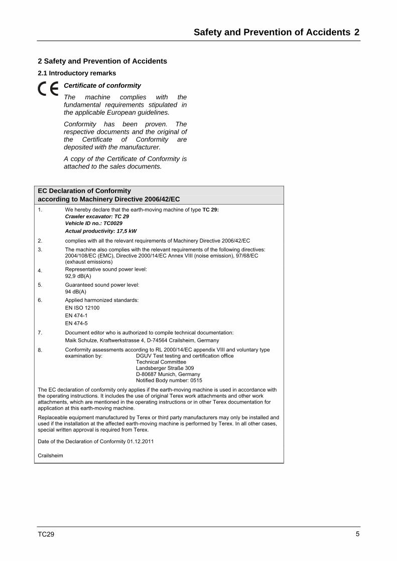
EC Declaration of Conformity according to Machinery Directive 2006/42/EC 1. We hereby declare that the earth-moving machine of type TC 29:
Crawler excavator: TC 29 Vehicle ID no.: TC0029 Actual productivity: 17,5 kW
2. complies with all the relevant requirements of Machinery Directive 2006/42/EC 3. The machine also complies with the relevant requirements of the following directives:
2004/108/EC (EMC), Directive 2000/14/EC Annex VIII (noise emission), 97/68/EC (exhaust emissions)
4. Representative sound power level: 92,9 dB(A)
5. Guaranteed sound power level: 94 dB(A)
6. Applied harmonized standards: EN ISO 12100 EN 474-1 EN 474-5
7. Document editor who is authorized to compile technical documentation: Maik Schulze, Kraftwerkstrasse 4, D-74564 Crailsheim, Germany
8. Conformity assessments according to RL 2000/14/EC appendix VIII and voluntary type examination by: DGUV Test testing and certification office Technical Committee Landsberger Straße 309 D-80687 Munich, Germany Notified Body number: 0515
The EC declaration of conformity only applies if the earth-moving machine is used in accordance with the operating instructions. It includes the use of original Terex work attachments and other work attachments, which are mentioned in the operating instructions or in other Terex documentation for application at this earth-moving machine.
Replaceable equipment manufactured by Terex or third party manufacturers may only be installed and used if the installation at the affected earth-moving machine is performed by Terex. In all other cases, special written approval is required from Terex.
Date of the Declaration of Conformity 01.12.2011
Crailsheim
2 Safety and Prevention of Accidents
TC29 6
Before putting the earth-moving machine into operation, read these operating instructions carefully and strictly observe the indicated references for safe operation.
National safety regulations - e.g. the Accident Prevention Regulations, "Earth-Moving Machinery" (BGR 500, 2.12) and "Vehicles" (BGV D29) in the Federal Republic of Germany - must also be complied with when operating the earth-moving machine.
In addition to the operating instructions, legal regulations governing road traffic and road safety measures must also be observed. Such requirements could also apply in respect of handling hazardous goods or the wearing of personal safety gear, for example.
Furthermore, safety laws governing work in particular locations (tunnels, adits, quarries, pontoons, contaminated areas, etc.) must likewise be observed.
2.2 Proper use
The earth-moving machine with standard bucket equipment is intended solely for work which is suitable for the function of the machine and its work implements.
Such work involves loosening, taking up, transporting and dumping soil, rock or other materials as well as loading these materials on trucks, conveyor belts or other means of transport.
The assembly of special work implements such as clamshell grab, hydraulic rock breaker, etc. allows the machine to perform above mentioned work.
Any usage above and beyond that specified here, e.g. the transport of persons or the transport of loading material and any non-compliance with the manufacturer’s instructions is regarded as improper use. The manufacturer shall not be liable for damage resulting from improper use. This risk is borne solely by the plant operator.
Compliance with the operating and maintenance instructions, the performance of maintenance work as specified and adherence to replacement intervals all form part of the concept of proper use.

Safety and Prevention of Accidents 2
TC29 7
2.3 General safety notes
It is important to refrain from any working methods which impair safety.
The earth-moving machine is only to be used with cab or canopy.
The earth-moving machine is only to be used when it is in a safe, operational condition.
The manufacturer’s instructions must be complied with for operation, maintenance, repair, assembly and transportation.
The plant operator must provide additional special safety instructions, wherever necessary, for specific local conditions.
The operating instructions and any information pertaining to safety must be carefully kept in the operator’s cab.
The operating instructions and safety notes must be complete and fully readable.
Safety devices on earth-moving machines shall not be deactivated or removed.
Protective work clothing must be worn during operation. Rings, scarves and unbuttoned jackets are to be avoided. Protective goggles, protective boots, helmets, gloves, reflecting jackets, ear-muffs, etc. may be required.
Before commencing work, information must be obtained on first aid and possible means of rescue (ambulance, fire brigade, helicopters).
A check must be carried out to ensure that the first aid box is at hand and that its contents comply with regulations.
Personnel must be aware of the location and method of operation of the fire extinguishers on the earth-moving machine as well as on-site fire-warning and fire-fighting equipment.
Loose parts such as tools or other accessories must be secured to the earth-moving machine.
Open doors, windows, covers, flaps, etc. must be closed or secured so that they cannot slam shut.
2.4 Operation
Earth-moving machines are only to be independently operated and serviced by persons who
• are physically and mentally suitable
• have been instructed in the operation or maintenance of earth-moving machines and have demonstrated this ability to the plant operator
• can be expected to perform their allocated duties reliably
All such persons must be of the legal minimum age.
They must be designated by the plant operator to operate or service the earth-moving machine.
Operating equipment is only to be operated from the driver's seat.
The earth-moving machine is only to be ascended and entered using the entrances and surfaces intended for this purpose.
It is the operator’s responsibility to ensure that the operator’s stand, entrances and other surfaces of the earth-moving machine which have to be stepped on are free of dirt, grease, oil, ice and snow.

2 Safety and Prevention of Accidents
TC29 8
2.5 Danger zone
No one is to enter the danger zone of earth-moving machines.
The danger zone encompasses the area around the earth-moving machine in which persons may be injured by movements of the earth-moving machine during operation, its work implements and attachments, or by swinging out or falling loads.
The machine operator is only to work the earth-moving machine when no one is in the danger zone.
The machine operator must give a warning signal to persons who may be in danger.
The machine operator shall stop work with the earth-moving machine if anyone remains in the danger zone despite the warning.
To ensure no danger of crushing, a sufficient safety distance (min. 0.5 m) must be kept from solid objects, e.g. buildings, excavation slopes, scaffolding, other machines, etc.
If the above safety distance cannot be maintained, the area between solid objects and the working zone of the earth-moving machine must be blocked off.
If conditions are such that the machine operator’s view of the driving and working zone is restricted, he must be guided or the driving and working zone must be marked by a solid barricade.
2.6 Transport of persons
The transport of persons on the machine is forbidden.
2.7 Stability
• The earth-moving machine must be used, driven and operated in such a manner that its stability against overturning is ensured at all times.
• The machine operator must drive at speeds which are suitable for local conditions.
• The permitted payload of the earth-moving machine shall not be exceeded.
• The earth-moving machine must remain at a sufficient distance from the edges of quarries, pits, mounds and slopes to ensure there is no risk of falling.
• Earth-moving machines must be secured so that they cannot roll or slip when in the vicinity of excavations, shafts, ditches, pits and slopes.

Safety and Prevention of Accidents 2
TC29 9
2.8 Travel operation
Before putting the earth-moving machine into operation, the driver's seat, mirrors and operator controls must be adjusted so as to ensure safe working.
A safety belt (seat belt), if installed, must always be fastened.
The windows must be clean and free of ice.
Driving tracks must be designed so as to ensure smooth, safe operation, i.e. they must be sufficiently wide, on ground which has as few slopes as possible and sufficient carrying capacity.
Downhill tracks must be set out in such a way that earth-moving machine can be safely braked.
Before driving downhill, the appropriate gear for the terrain must be selected and the gear lever shall not be moved during downhill travel (on-highway / off-highway gear).
On steep drops and uphill gradients, the load must be carried on the uphill side, if possible, in order to increase stability.
The carrying capacity of bridges, cellar roofs, vaults, etc. must be verified before the earth-moving machine can drive over them.
The internal dimensions of constructions must be noted before entering underground passages, tunnels, etc.
It is the plant operator's responsibility to ensure that equipment such as first-aid box, warning triangle, hazard lights are kept with the machine according to the traffic regulations valid in the user’s country (e.g. in Germany "StVZO") and that the driver has the appropriate license as required by the national traffic laws of the country in question.
Outside areas covered by general traffic regulations, e.g. on construction sites, traffic regulations should be applied in the proper manner. This should also apply with regard to drivers’ licenses.
2.9 Operation
Daily before commencing work and after every change of work attachments, the machine operator must check the correct fastening of the work attachments as well as the correct locking of the quick-mount hitch (QMH). Work attachments are to be carefully moved at low height. During this check no one shall be in the danger zone of earth-moving machines.
The machine operator is only to swing the work equipment over occupied driver's seats, operator consoles and workplaces of other machines when these are protected by canopies (FOPS).
If a cab does not have the required protection, the driver of this vehicle must leave the operator’s stand when the work equipment has to be slewed overhead.
The vehicles must be loaded in such a manner as to ensure that there is no overloading and no material can be lost during travel. The vehicle must be loaded from the lowest possible height.
At dumping points, earth-moving machines are only to be operated when suitable measures have been taken to prevent rolling or falling.
2 Safety and Prevention of Accidents
TC29 10
2.10 Guides
Guides must be easily recognizable, e.g. by means of reflective clothing. They must remain within the machine operator’s field of vision.
While guiding the machine, guides shall not be given other jobs which may distract them from their task.
2.11 Danger of falling objects
Earth-moving machines are only to be used where there is a danger of falling objects when the operator’s stand has a canopy (FOPS). A front guard must be employed if there is a risk of materials breaking into the cab.
In front of walls e.g. of stacked materials, earth-moving machines must be positioned and operated in such a way that the driver's seat and entry to the driver's seat are not situated on the side facing the wall.
Demolition work is only to be performed by earth-moving machines where there is no danger to persons and if the machine is equipped with canopy, cab-mounted front guard and the appropriate work implement.
See regulations book "Demolition work" (ZH 1/614) published by the Tiefbau-Berufsgenossenschaft (the employer’s liability insurance association).
2.12 Working in the vicinity of underground power lines
Before commencing excavating work using earth-moving machines, it must be determined whether any underground power lines are present in the intended working zone which may present a danger to persons.
If underground power lines are present, their exact position and course must be determined in consultation with the proprietor or operator of the lines, and the necessary safety precautions decided and implemented.
The course of power lines in the work area must be clearly marked, under supervision, before commencing any excavation work. If the position of lines cannot be determined, search ditches must be dug - manually, if need be.
If underground power lines are encountered unexpectedly or they or their protective covers are damaged, the machine operator must discontinue work immediately and notify the supervisor.

Safety and Prevention of Accidents 2
TC29 11
2.13 Working in the vicinity of overhead power lines
When the earth-moving machine is being used in the vicinity of overhead power lines and trolley wires, a safety distance which varies depending upon the nominal voltage of the overhead line must be maintained between the lines and the earth-moving machine and its work equipment, in order to prevent current overspill. This also applies to the distance between these lines and attached implements or loads.
The safety distances specified below must be complied with:
Nominal voltage in Volt
Safety distance in meters
- 1,000 V 1.0 m
over 1 kV - 110 kV 3.0 m
over 110 kV - 220 kV 4.0 m
over 220 kV - 380 kV 5.0 m
nom. voltage unknown 5.0 m
In the observation of safety distances, all working movements of earth-moving machines, e.g. positions of the work equipment and the dimensions of attached loads must be taken into consideration. Uneven ground which would cause the earth-moving machine to be inclined and thus nearer to overhead lines must also be taken into account.
During work in windy conditions, both overhead lines and work equipment may swing out, thus reducing the safety distance.
If it is impossible to maintain sufficient distance from overhead power lines and trolley wires, the plant operator must consult with the proprietor or operator of the overhead lines to find other safety precautions to prevent current overspill. Such measures could be e.g.
• Switching off the current
• Re-routing the overhead line
• Cabling, or
• Limiting the work zone of earth-moving machines
2.14 Operation in closed rooms
If earth-moving machines are to be used in closed rooms, these areas must be sufficiently ventilated and special regulations observed.
2.15 Work stoppages
Before rest periods and at the end of the working day, the driver of the earth-moving machine must park the machine on ground which has sufficient carrying capacity and is as level as possible, and must secure it against unintended movement.
Before rest periods and at the end of the working day, the driver must lower the work equipment onto the ground or secure it so that it cannot move about.
The driver is not to leave the earth-moving machine when the work equipment has not been lowered to the ground or secured.
Earth-moving machines are only to be parked in places where they do not present an obstacle, e.g. on the construction site or to plant traffic. Warning devices, e.g. triangles, warning cordons, flashing or hazard lights are to be used if necessary.
Before leaving the operator stand, the driver must bring all operating equipment into home position, switch off the working hydraulics and apply the brakes.
If the driver is leaving the earth-moving machine unattended, he must first turn off the drive motors and ensure that they cannot be started up by unauthorized persons (e.g. removing ignition keys).

2 Safety and Prevention of Accidents
TC29 12
2.16 Load hook applications
Load hook applications are the hoisting, transporting and lowering of loads with the aid of a fixing device (rope, chain, etc.), whereby the assistance of personnel is required to attach and release the load. Such work covers e.g. the lifting and lowering of pipes, tubbing rings or containers using earth-moving machines.
Earth-moving machines are only to be used for load hook applications when the prescribed safety devices are present and in full working order. For earth-moving machines, these are:
• Secure attachment of loading implements
• Table of carrying capacity
• Overload warning device *
• Hose-rupture valve in boom cylinder *
* only if the permissible carrying capacity exceeds 1,000 kg
Loads must be attached in such a way that they cannot slip or fall out.
Personnel guiding the machine and attaching loads shall always remain in the machine operator’s field of sight.
The machine operator must carry loads as close to the ground as possible and prevent them from swinging.
Earth-moving machines are only to travel with an attached load if the path of travel is fairly level.
When earth-moving machines are used for load hook applications, personnel attaching loads is only to approach the boom from the side and with the machine operator’s permission. The machine operator is only to give his permission if the earth-moving machine is standing still and the work equipment is not in motion.
Do not use fixing devices (ropes, chains, shackles) which are damaged or of inadequate dimensions. Protective gloves must always be worn when working with fixing devices.
2.17 Change of work attachments, maintenance, repair
Earth-moving machines are only to be converted, maintained or serviced under the guidance of a suitable person designated by the plant operator and following the manufacturer’s operating instructions.
After every change of work attachments, the driver must convince himself that the quick-mount hitch is correctly fastened and locked.
Work on e.g.
• braking
• steering
• hydraulic and
• electric systems
of the machine is only to be carried out by expert personnel specially trained in these areas.
Stability must be ensured during all type of work on the machine at all times.
Whenever performing work on and especially under the machine, the machine must be suitably secured by chocks so that it cannot roll away.
The work equipment must be secured against movement by lowering it to the ground or equivalent measures, e.g. cylinder supports, trestles. With the engine running, the unprotected operating envelope of the machine shall not be entered.
When jacking up earth-moving machines, jacking devices must be positioned so that they cannot slip. Jacks must be positioned and applied absolutely straight, without tilting.
Raised earth-moving machines must be supported by suitable structures such as crosswise stacks of planks, square timbers or steel trusses.
Earth-moving machines which are raised with work equipment must be stabilized by a supporting structure immediately after lifting. Work under raised machines which are only supported by their hydraulics is forbidden.

Safety and Prevention of Accidents 2
TC29 13
The engine/motor(s) must be turned off prior to all maintenance and repair work. These requirements are only to be ignored in the case of maintenance or repair work which cannot be performed without the engine/motor(s) running.
When performing maintenance and repair work on the hydraulic system, the hydraulic system must be relieved of pressure. With the engine turned off, lower the work equipment to the ground and actuate all hydraulic control levers until there is no pressure in the hydraulic system.
Before working on the electrics or when performing arc-welding on the machine, the connection to the battery must be interrupted.
When disconnecting the battery, first the negative pole then the positive pole must be disconnected. The battery must be re-connected in reverse order.
During repair work around the battery, the battery must be covered with insulating material. Tools should never be placed on or near the battery.
Protective devices of moving machine parts are only to be opened or removed when the drive has been switched off and cannot be switched on again by unauthorized persons. Protective devices are e.g. engine/motor covers, doors, protective grating, trim.
Upon completion of assembly, maintenance or repair work, all protective devices must once more be attached in the proper manner.
Load-bearing parts of earth-moving machines are only to be welded following consultation with the manufacturer and in accordance with recognized welding principles.
Protective structures (TOPS, ROPS; FOPS) are not to be welded or drilled in any way.
Alterations, such as welding of the hydraulic system, are only to be undertaken with the manufacturer’s permission.
Before commencing work on the hydraulic system, the operating pressure, pilot pressure, back pressure and pressure inside the tank must be let off.
Swallowing lubricants as well as long and repeated skin contact can be hazardous to health and should therefore be avoided. When used properly, there is no particular danger to health. The safety specification sheets from the mineral companies must be observed.
Only the hoses specified by the manufacturer may be used.
Hydraulic hoses must be routed and assembled by expert personnel.
In the vicinity of fuel or batteries, smoking and naked flames are prohibited.
2.18 Recovery, loading, transportation
Earth-moving machines are only to be loaded onto recovery vehicles when adequate towing vehicles are used.
The tow fixing points specified by the manufacturer must be employed.
For loading and transportation, earth-moving machines and all necessary auxiliary equipment must be secured against unwanted movement.
The travelling gear and crawler unit of earth-moving machines must be sufficiently cleaned of mud, snow and ice to ensure that ramps can be driven up without risk of slipping.
When transporting the earth-moving machine on trucks, flatbed trailers, or by rail, it must be sufficiently secured with chocks and by attachment to the lashing points.
Before setting off, the route to be taken must be examined to determine whether the roads are wide enough, entrances and passages under bridges are large enough and that roads and bridges have sufficient carrying capacity.
2 Safety and Prevention of Accidents
TC29 14
2.19 Monitoring and inspections
The machine must be submitted to a general inspection according to the existing UVV-regulations (Accident Prevention Regulations). This inspection must be carried out by an expert (e.g. machine engineer or machine foreman):
• before the machine is put into operation for the first time and before the machine is again put into operation when essential modifications have been made
• at least once a year
• in the meantime, according to operating conditions and local environments
The results of this inspection have to be recorded in writing and this record has to be kept until the next inspection takes place.
Prior to every work shift, the machine operator must check the earth-moving machine according to the inspection and maintenance plan.
Hydraulic hoses must be replaced as soon as the following damage is recognized:
• Damage to the outer layer which reaches the intermediate layer
• Embrittled patches on the outer layer
• Deformations when under pressure or without pressure which differ from the original shape of the installed hose
• Leaks
• Damage to hose fittings or to the connection between the fitting and the hose
The coolant level shall only be checked after the engine has cooled down; the cap must be turned carefully in order to let off excess pressure.
Prior to operations, the machine operator must check the function of the safety devices.
The machine operator must advise the supervisor immediately - and his replacement, if there is a change of operator - with regard to any shortcomings.
In the event of shortcomings which jeopardize the operating safety of the earth-moving machine, it shall not be used until these have been eliminated.
2.20 Fire protection
• Before refueling the tank of the machine, the engine must be stopped. Exercise special caution as long as the engine is hot.
• Never smoke or handle open flames whilst refueling the tank of the machine.
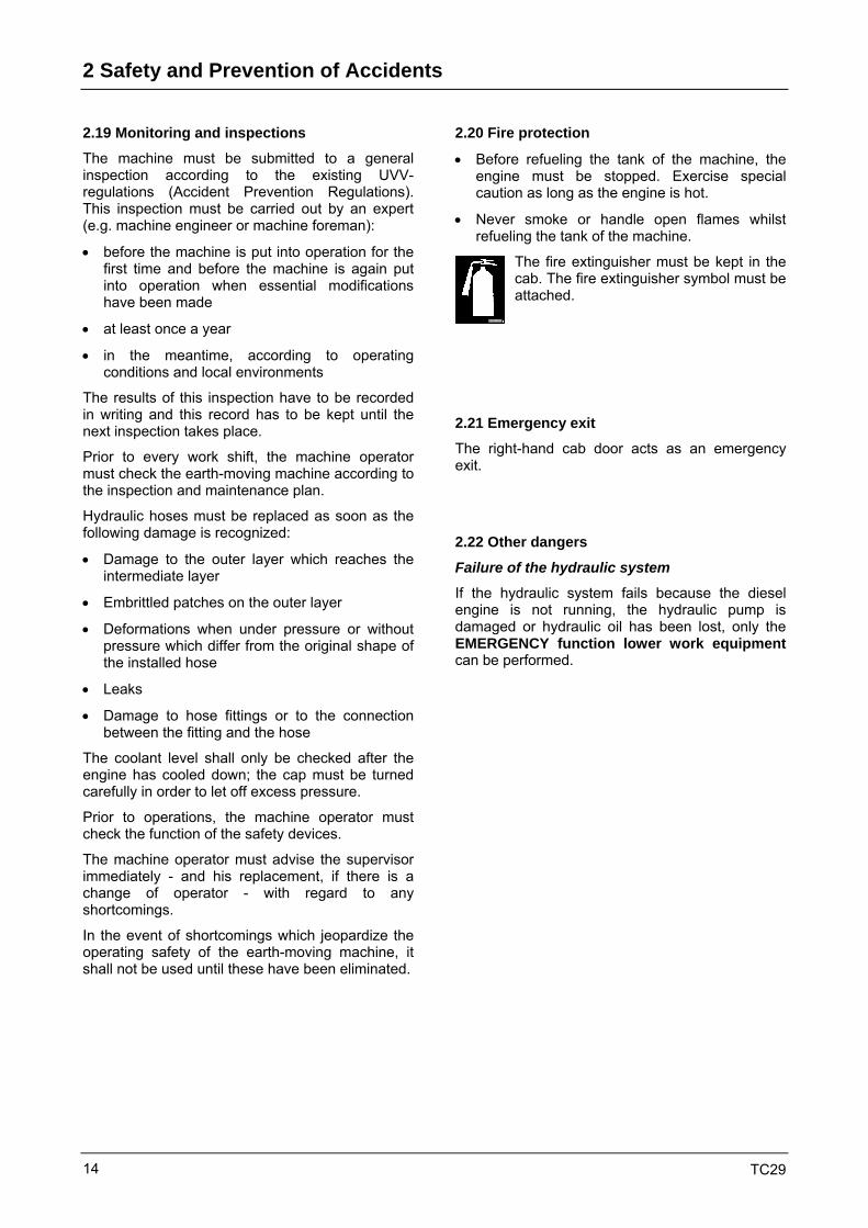
The fire extinguisher must be kept in the cab. The fire extinguisher symbol must be attached.
2.21 Emergency exit
The right-hand cab door acts as an emergency exit.
2.22 Other dangers
Failure of the hydraulic system
If the hydraulic system fails because the diesel engine is not running, the hydraulic pump is damaged or hydraulic oil has been lost, only the EMERGENCY function lower work equipment can be performed.
MTK115002

Technical Data 3
TC29 15
3 Technical data 3.1 Views
0 1 2 3 4123455 4
12
34
50
54
32
1
3214 3 2 1 06
6
30002480
3680
3460
2655
2435
4885
4990
2960
2320
1550
4190
3600
2960
2760
2120
1500
4805
3475
2835
4065
2310
2530
3260
3480
4700
Löffe
lstie
l/Arm
135
0 m
mLö
ffels
tiel/A
rm 1
550
mm
HR
14-0
3-03
Fig. 3-Digging envelope
Dip
pers
tick/
Arm
135
0 m
m
Dip
pers
tick/
Arm
155
0 m
m
3 Technical Data
TC29 16
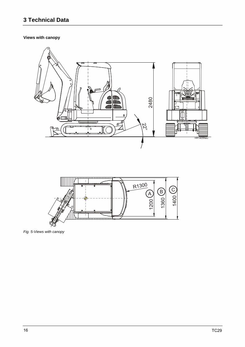
Views with canopy
Fig. 5-Views with canopy
Technical Data 3
TC29 17
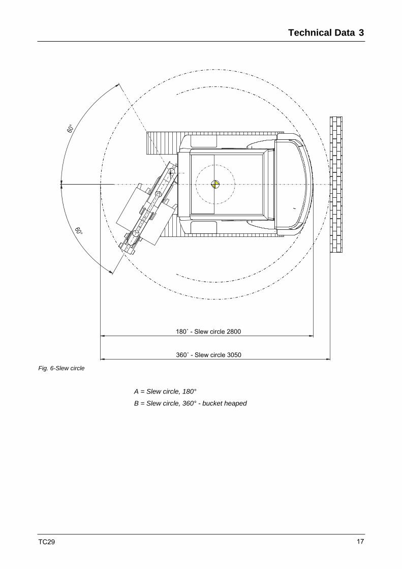
Fig. 6-Slew circle
A = Slew circle, 180°
B = Slew circle, 360° - bucket heaped
180˚ - Slew circle 2800
360˚ - Slew circle 3050

3 Technical Data
TC29 18
3.2 Engine
Make Mitsubishi four-stroke diesel engine, swirl chamber
Type/Model: S4L-W462KL, EPA Tier 4 Final
Stroke displacement 1,500 cm3
Power rating acc. to ISO 9249 (DIN 70020) 17.5 kW (23.8 PS) at 2,000 rpm
Max. torque 84 Nm at n = 1,800 rpm
Permissible inclined positions Continuously on all sides 25° Briefly on all sides 30° (max. 30 minutes)
Specific fuel consumption 262 g/kWh
3.3 Electrical system
Nominal voltage 12 V
Battery 12 V 71 Ah
Generator 12 V 50 A
Starter 12 V 2.0 kW
Lighting system 1 halogen working floodlight H3 front left on the cab
3.4 Crawler-type undercarriage
Crawler-type undercarriage Maintenance-free crawler-type undercarriage. Idler suspension with hydraulic crawler-chain tension.
Travel speed Forward - reverse Range 1 0 – 2.7 km/h Range 2 0 – 4.6 km/h
Max. gradability 60%
Power transmission Two-stage hydrostatic travel drive with axial piston variable displacement motor and reduction gear, fully enclosed; brake valves for traveling downhill.
Crawler-chain width Steel or rubber, 300 mm
Overall length of undercarriage 1,830 mm

Technical Data 3
TC29 19
3.5 Steering
Traveling - steering Independent, individual control of crawler chains, including in opposite directions. Sensitive operation via hand levers combined with foot pedals, left and right foot rest on pedal console.
3.6 Brakes
Swing drive The hydrostatic swing drive acts as a maintenance-free swing brake. Additional spring-operated multiple-plate brake acting as parking brake when the swing lever is in neutral position.
3.7 Hydraulic system
Working hydraulics Single-stage, load-sensing controlled displacement axial piston pump Pump capacity ...........................max. 99 l/min Pressure max. 210 bar
Excavator equipment Hydraulically pilot-operated control valve for the functions "boom, dipper stick, dipper, slewing of uppercarriage" 28 bar pilot pressure with pressure accumulator Proportional control of all functions
Additional control circuit Control circuit for grab, hammer, etc. Pump flow (pressure-dependent): 40 l/min at 120 bar 33 l/min at 180 bar Max. pressure 210 bar
Hydraulic filter Full flow filtration
Hydraulic cylinders Double-acting work cylinders, partially with end-position damping
Slewing gear Internally-toothed slew ring, teeth can be lubricated from driver's seat during slewing. Slewing range: 360° Uppercarriage slewing speed: 0 – 9.5 rpm

3 Technical Data
TC29 20
Knickmatik® Right: Swing angle 60° Left: Swing angle 60° Parallel lateral adjustment at full digging depth, total 1,040 mm to the right 595 mm to the left 445 mm
Dozer blade Independent from drive, sensitive control by means of hand lever.
Short version* Long version
Width 1,410 mm 1,410 mm
Height 325 mm 325 mm
Lift below road level 285 mm 296 mm
Lift above road level 206 mm 406 mm
Slope angle 22° 28°
Slope balance 9.0° 8.0°
*virtually full digging depth can be achieved even when articulated
3.8 Lubricants
3.8.1 Filling quantities
The level marking is always the decisive factor.
Diesel fuel approx. ltr. 52.0 Diesel
Engine oil, engine and filter approx. ltr. 7.9 + 0.5 High pressure oil (change quantity)
Hydraulic oil: Tank approx. ltr. 72.0 Hydraulic oil (change quantity)
Hydraulic oil: Total system approx. ltr. 85.0 Hydraulic oil
Crawler gear units each approx. 0.6 transmission oil
Swing gear circulation lubrication provided by hydraulic system
Coolant approx. ltr. 5.3 water with anti-corrosion agent and antifreeze *
* The ratio of mixture must be adjusted to the level of antifreeze required.
All values stated are approximate.
Technical Data 3
TC29 21
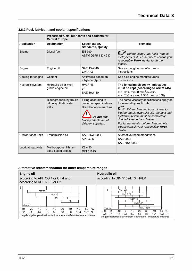
3.8.2 Fuel, lubricant and coolant specifications
Prescribed fuels, lubricants and coolants for Central Europe
Application Designation Specification, Standards, Quality
Remarks
Engine Diesel fuel EN 590 ASTM D975 1-D / 2-D Before using RME-fuels (rape oil
methyl ester), it is essential to consult your responsible Terex dealer for further details.
Engine Engine oil SAE 15W-40 API CF4
See also engine manufacturer’s instructions
Cooling for engine Coolant Antifreeze based on ethylene glycol
See also engine manufacturer’s instructions
Hydraulic system
Hydraulic oil or multi-grade engine oil
HVLP 46 or SAE 10W-40
The following viscosity limit values must be kept (according to ASTM 445) at 100° C min. 8 mm 2/s (cSt) at -10° C approx. 1,500 mm 2/s (cSt)
Biodegradable hydraulic oil on synthetic ester base
Filling according to customer specifications. Brand label on machine.
Do not mix biodegradable oils of different suppliers.
The same viscosity specifications apply as for mineral hydraulic oils.
When changing from mineral to biodegradable hydraulic oils, the tank and hydraulic system must be completely drained, cleaned and flushed. For further details before changing oils, please consult your responsible Terex dealer.
Crawler gear units Transmission oil SAE 85W-90LS API-GL 5
Alternative recommendations SAE 90LS SAE 80W-90LS
Lubricating points Multi-purpose, lithium-soap based grease
K2K-30 DIN 51825
Alternative recommendation for other temperature ranges
Engine oil according to API CG 4 or CF 4 and according to ACEA E3 or E2
Hydraulic oil according to DIN 51524.T3 HVLP
6

3 Technical Data
TC29 22
3.9 Specific ground pressure
Specifications without bucket and without driver
with rubber crawler chains
with steel crawler chains
Basic machine with cab 0.26 da N/cm² 0.27 da N/cm²
Basic machine with cab 0.27 da N/cm² 0.28 da N/cm²
3.10 Sound level values, vibration
Sound level values in compliance with directive 2000/14/EC and EN 474
Cabin Canopy
Guaranteed sound power level LW(A) = 94 dB (A) LW(A) = 94 dB (A)
Sound pressure level, driver's seat LP(A) = 76 dB (A) LP(A) = … dB (A)
Vibration values in compliance with directive 2002/44/EC and EN 474
Weighted r.m.s. value of acceleration is below 0.5 m/s2 for entire body
and 2.5 m/s2 for upper limbs
3.10.1 Equivalent vibration values
Equivalent vibration values for entire body vibration emission according to ISO/TR 25398
Average value Standard deviation
1.4*αw,eqx 1.4*αw,eqy aw,eqz 1.4*Sx 1.4*Sy Sz Type of machine
Typical operating condition
m/s²
Excavating 0.33 0.21 0.19 0.19 0.12 0.10
Hydr. hammer application 0.49 0.28 0.36 0.20 0.13 0.17
Compact crawler
excavator ≤ 6,000 kg
Traveling 0.45 0.39 0.62 0.17 0.18 0.28

Technical Data 3
TC29 23
3.11 Dimensions and weights
Dipper stick mm 1,350
Basic machine with rubber track,
dipper 400 mm, without driver kg 2,690
Basic machine with steel track,
dipper 400 mm, without driver kg 2,780
Total width, undercarriage mm 1,400
Total width, uppercarriage (on rear) mm 1,360
Total length (travel position) mm 3,100
Total length (transport position) mm 4,700
Total height (travel position) mm 3,000
Total height (driver's cab) mm 2,480
Uppercarriage rear radius mm 1,300
Ground clearance mm 270
Drawbar pull 1st gear da N 2,600
2nd gear da N 1,100
Excavator installation
Dimensions apply to machine standing on level ground
With dipper stick mm 1,350 1,550
Digging depth max. 1) mm 2,760 2,960
Lowest dipper hinge point 1) mm 2120 2,320
Maximum possible height 1) mm 4,065 4,190
Discharge height 1) mm 2,835 2,960
Highest dipper hinge point 1) mm 3,475 3,600
Max. reach mm 4,805 4,990
Dipper angle of rotation ° 185 185
Ripping force in accordance with DIN 24086 N 13,600 11,900
Breakout force in accordance with DIN 24086 N 21,300 21,300
1) Dimensions apply to machine standing on level ground, but can be increased by tilting the machine using the blade.

3 Technical Data
TC29 24
3.12 Carrying capacity
The stated carrying capacities in tons (t) were determined in compliance with ISO 10567 and include a stability factor of 1.33, or 87% of the hydraulic lifting load capacity.
The dead-weight of the work attachment must be deducted from the stated carrying capacity!
Table of carrying capacity with the following equipment:
• including quick-mount hitch
• without bucket
• rubber crawler chain, 300 mm wide
• full tank, with driver
Working envelope for grab, see Chapter 3.11
• with dipperstick 1,350 mm A = supported by blade V = travelling
Load radius from center of ring gear in m
2.0 2.5 3.0 3.5 4.0 along* across* along* across* along* across* along* across* along* across*
2 A -- -- 0.83 0.68 0.78 0.54 0.66 0.39 -- --
V -- -- 0.68 0.66 0.53 0.53 0.38 0.38 -- --
1 A 1.41 0.94 1.04 0.67 0.91 0.51 0.77 0.38 0.54 0.32
V 0.85 0.93 0.67 0.66 0.45 0.49 0.36 0.37 0.30 0.31
0 A 1.35 0.81 0.98 0.58 0.75 0.48 0.62 0.37 0.52 0.32
V 0.76 0.78 0.56 0.57 0.45 0.46 0.35 0.36 0.29 0.30
-1.0 A 1.04 0.88 0.85 0.52 0.68 0.46 0.45 0.37 -- --
Buc
ket h
inge
hei
ght
in m
V 0.75 0.82 0.50 0.51 0.43 0.45 0.35 0.36 -- -- • with dipperstick, 1,550 mm
A = supported by blade V = travelling
Load radius from center of ring gear in m
2.0 2.5 3.0 3.5 4.0 along* across* along* across* along* across* along* across* along* across*
2 A -- -- 0.83 0.68 0.78 0.54 0.65 0.38 -- --
V -- -- 0.68 0.66 0.53 0.53 0.37 0.37 -- --
1 A 1.41 0.94 1.04 0.67 0.91 0.51 0.76 0.37 0.52 0.30
V 0.85 0.93 0.67 0.66 0.45 0.49 0.35 0.36 0.28 0.29
0 A 1.35 0.81 0.98 0.58 0.75 0.48 0.61 0.36 0.50 0.30
V 0.76 0.78 0.56 0.57 0.45 0.46 0.34 0.35 0.27 0.28
-1.0 A 1.04 0.88 0.85 0.52 0.68 0.46 0.44 0.36 -- --
Buc
ket h
inge
hei
ght
in m
V 0.75 0.82 0.50 0.51 0.43 0.45 0.34 0.35 -- --

Technical Data 3
TC29 25
3.13 Working range for grab operations
For safety reasons, ensure that the indicated reaches are not exceeded when the grab is full.
Danger of tilting!
Fig. 8 Grab working range
A = max. reach
B = restricted reach
max.3.0 m

3 Technical Data
TC29 26
3.14 Work attachments
X = available
Width mm
QMH Direct attachment
Capacity m3
Density t/m3
Buckets quick-mounting
directly attached
260 X 38 1.8
260 ejector X 38 1.8
300 X 40 1.8
300 ejector X 45 1.8
400 X X 56 63 1.8
500 X X 73 80 1.8
600 X X 89 97 1.8 *
Ditch-cleaning bucket
1,000 X 110 1.8 *
Swing bucket
1,000 X 96 1.8 *
Clamshell grabs
GL1-250 X 45 1.8
GL1-350 X 65 1.8
GL1-450 X 85 1.8 *
Hydraulic rock breaker
Type SH 70/SMS X
* "extra-long" dipperstick (1,550 mm): max. density of 1.6 t/m3
Additional work attachments available upon request!

Technical Data 3
TC29 27
3.15 Optional equipment
• Crane lifting beam for cab suspension
• Crane lifting beam for canopy suspension
• Comfort seat, height-adjustable, height and tilt-adjustable seat upholstery
• Adapter for rock breaker attachment
• Felasto track shoes for steel crawler chain
• Dual ripper tooth
• Load hook on bucket rod (bolt-on connection)
• Digital immobilizer
• Diverse electrical equipment such as additional work floodlights, rotating beacon, radio, etc.
Further additional equipment available on request!
Any modifications of Terex products and their equipment using extras and work attachments which are not included in our product range require our written approval. If our approval is not sought, our warranty expires, as does our product liability for any resulting consequential damage.

3 Technical Data
TC29 28

Operation 4
TC29 29
4 Operation 4.1 First commissioning
If you are not familiar with the operator controls and display elements of this machine, read this chapter carefully before operating the machine.
This chapter describes all the functions.
Before putting the machine into motion and operation you must familiarize yourself thoroughly with the display elements and operator controls.
Before the machine is placed into operation, it must be subjected to a thorough visual inspection each time. Take care to ensure that there is no damage and that there are no loose or missing screws, oil deposits, or oil/fuel leaks. Any defects must be remedied immediately. In the event of defects which jeopardize operating safety, the machine must not be placed into operation until these have been eliminated.
Before placing the machine into operation, the inspections outlined in Chapter 7.5 must be carried out each time.
4 Operation
TC29 30
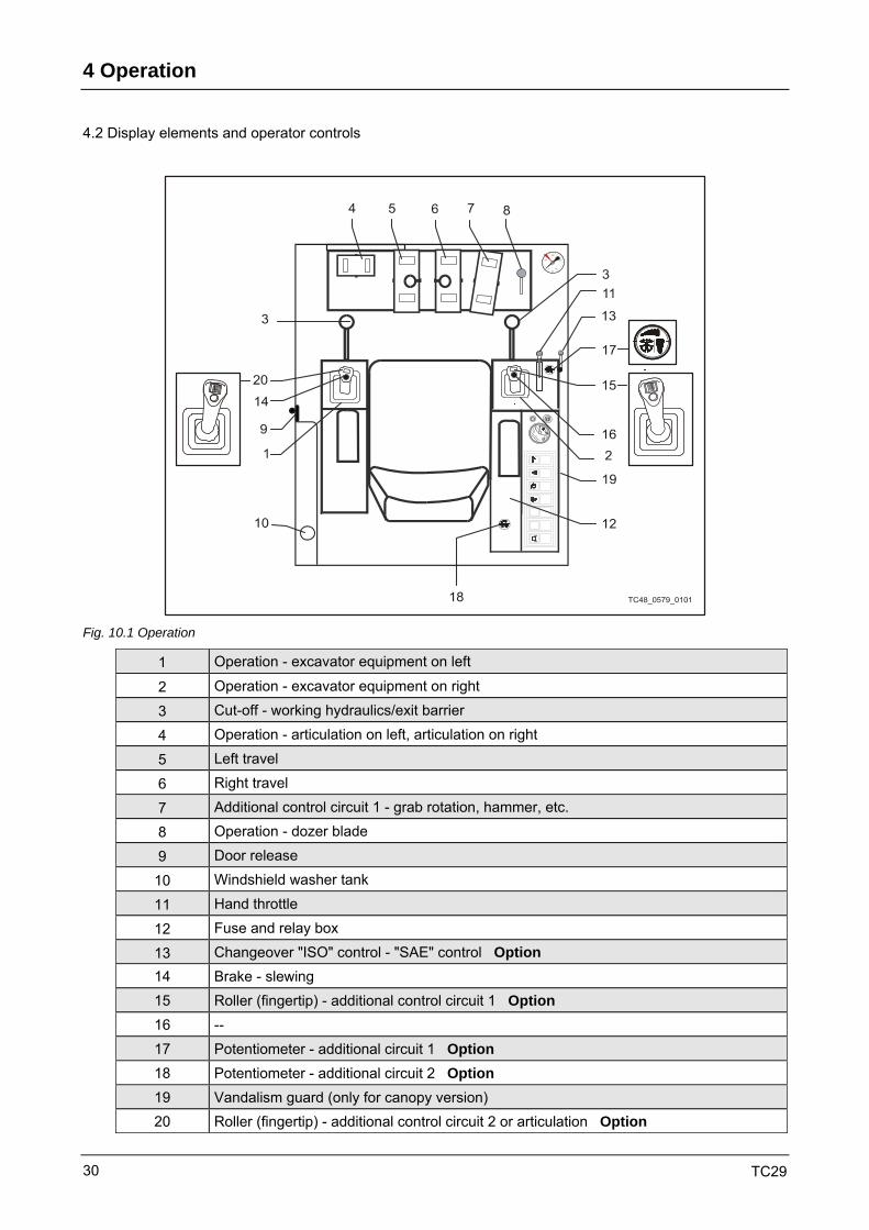
4.2 Display elements and operator controls
Fig. 10.1 Operation
1 Operation - excavator equipment on left
2 Operation - excavator equipment on right
3 Cut-off - working hydraulics/exit barrier
4 Operation - articulation on left, articulation on right
5 Left travel
6 Right travel
7 Additional control circuit 1 - grab rotation, hammer, etc.
8 Operation - dozer blade
9 Door release
10 Windshield washer tank
11 Hand throttle
12 Fuse and relay box
13 Changeover "ISO" control - "SAE" control Option 14 Brake - slewing 15 Roller (fingertip) - additional control circuit 1 Option 16 -- 17 Potentiometer - additional circuit 1 Option 18 Potentiometer - additional circuit 2 Option 19 Vandalism guard (only for canopy version) 20 Roller (fingertip) - additional control circuit 2 or articulation Option
Operation 4
TC29 31
ROT_TC48_0102_0579
31 33 32
34
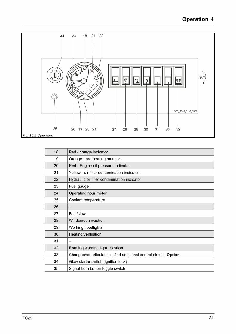
35 Fig. 10.2 Operation
18 Red - charge indicator
19 Orange - pre-heating monitor
20 Red - Engine oil pressure indicator
21 Yellow - air filter contamination indicator
22 Hydraulic oil filter contamination indicator
23 Fuel gauge
24 Operating hour meter
25 Coolant temperature
26 -- 27 Fast/slow
28 Windscreen washer
29 Working floodlights
30 Heating/ventilation
31 --
32 Rotating warning light Option
33 Changeover articulation - 2nd additional control circuit Option
34 Glow starter switch (ignition lock)
35 Signal horn button toggle switch

4 Operation
TC29 32
4.2 Engine
4.2.1 Starting the engine
Before placing the machine into operation, the inspections outlined in Chapter 7.7 must be carried out each time.
Before starting the engine, take care to ensure that no one is in the immediate vicinity of the machine or in the danger zone.
• All gearshift levers to neutral.
• Insert ignition key in pre-heat/starter switch (11/34).
• Turn clockwise to "1"; indicator lamps (11/18, 11/20) light up.
• Pre-heating starts; control light (11/19) lights up.
In the event of a cold start, the throttle handle must be fully open. Reduce the throttle when the engine is running smoothly!
• After the control light (11/19) has gone out, turn the pre-heat/starter switch to "2". As soon as the engine is running, turn the ignition key to "1" and decrease the revs to low idle speed. Control lights must go out.
• If the engine has not started after max. 30 sec., turn the ignition key to "1" or "O", and wait for at least 1 minute before trying again. Repeat the start-up procedure.
• If the engine has not started after 2 start-up procedures, determine the source of the fault.
Do not drive the engine at full throttle straight away. Drive with restraint until the operating temperature of the engine has been reached.
Fig. 11-Operation
Operation 4
TC29 33
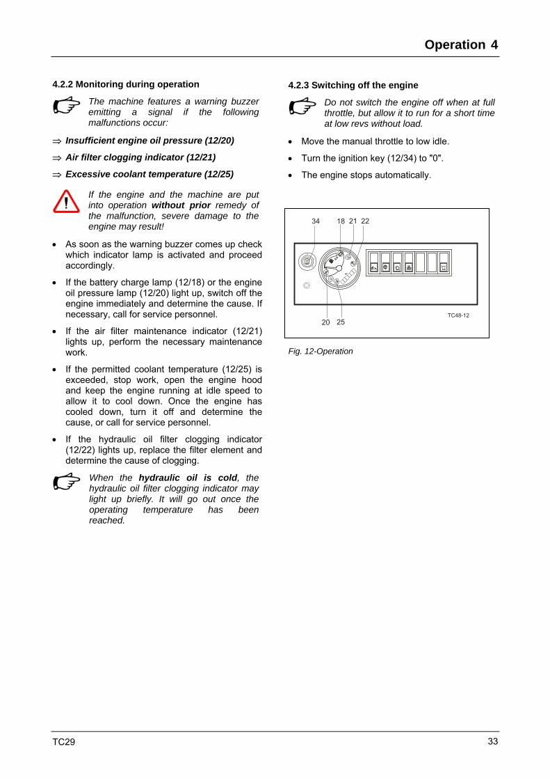
4.2.2 Monitoring during operation
The machine features a warning buzzer emitting a signal if the following malfunctions occur:
⇒ Insufficient engine oil pressure (12/20)
⇒ Air filter clogging indicator (12/21)
⇒ Excessive coolant temperature (12/25)
If the engine and the machine are put into operation without prior remedy of the malfunction, severe damage to the engine may result!
• As soon as the warning buzzer comes up check which indicator lamp is activated and proceed accordingly.
• If the battery charge lamp (12/18) or the engine oil pressure lamp (12/20) light up, switch off the engine immediately and determine the cause. If necessary, call for service personnel.
• If the air filter maintenance indicator (12/21) lights up, perform the necessary maintenance work.
• If the permitted coolant temperature (12/25) is exceeded, stop work, open the engine hood and keep the engine running at idle speed to allow it to cool down. Once the engine has cooled down, turn it off and determine the cause, or call for service personnel.
• If the hydraulic oil filter clogging indicator (12/22) lights up, replace the filter element and determine the cause of clogging.
When the hydraulic oil is cold, the hydraulic oil filter clogging indicator may light up briefly. It will go out once the operating temperature has been reached.
4.2.3 Switching off the engine
Do not switch the engine off when at full throttle, but allow it to run for a short time at low revs without load.
• Move the manual throttle to low idle.
• Turn the ignition key (12/34) to "0".
• The engine stops automatically.
TC48-12
34 18 21 22
2520
Fig. 12-Operation

4 Operation
TC29 34
4.3 Driver's seat
The comfort seat meets international quality and safety standards (Fig. 13).
1. Horizontal adjustment of seat
2. Seat back inclination adjustment
3. Handle for weight adjustment
• 9-setting weight adjustments (10 kg each).
• Move the weight adjustment handle clockwise until the stop; the weight adjustment switches automatically to the 50 kg position.
4.4 Heating / Ventilation
Heating • Before the heater is switched on, the "engine
compartment" hot water supply (14/1) must be turned on.
• The heater, which is connected to the coolant circuit, is operated using the switch (15/30).
• The hot air is distributed and aimed as desired via a front windshield nozzle in the pedal console and by adjusting the air vent on the seat console.
Ventilation • In ventilating mode, the hot water supply (14/1)
remains turned off.
• The fan is operated using the switch (15/30).
• The air is distributed and aimed as desired by adjusting the windshield air nozzle in the pedal console and by an adjustable air vent on the seat console.
Fig. 13-Driver's seat
Fig. 14-Heating
TC35-03-15
30
Fig. 15-Operation

Operation 4
TC29 35
4.5 Front window
• To open the windshield, release the two levers (16/1).
• Pull the window back and up at the same time.
• Lock the window in the upper position with the levers (16/1).
Ventilation position • Release the two levers (16/1).
• Pull the window back approx. 10 cm.
• Lock the levers. The window is left open a crack.
Fig. 16-Windshield

4 Operation
TC29 36
4.6 Tracking and steering
The travel direction always relates to the undercarriage (travel drive at the rear, dozer blade in front).
Incorrect handling may endanger persons or objects.
Before lifting the exit barrier (17/2) and leaving the machine, the engine must be switched off.
Activating the speed range Use switch (17/27) to activate the desired speed range.
When the switch (17/27) is in the "Fast" position, the machine automatically switches from the slow speed range to the higher speed range.
• Rocker pedal / hand lever (17/6), right-hand crawler chain:
A. Forward
B. Reverse
• Rocker pedal / hand lever (17/5), left-hand crawler chain:
C. Forward
D. Reverse
Tracking forward or reversing
• Operate right-hand (17/6) and left-hand (17/5) rocker pedal / hand lever forward or backward in a regular manner.
Taking bends
• Reduce the speed of one crawler chain according to the bend.
Spot-turning
• Operate the rocker pedal / hand lever for the right-hand and left-hand crawler chain in an opposed manner.
Turning over one crawler chain
• Operate the rocker pedal / hand lever for the right-hand or left-hand crawler chain.
Fig. 17 – Tracking

Operation 4
TC29 37
4.7 Rubber crawler chains
This crawler excavator can be equipped with steel crawler or rubber crawler chains.
When equipped with a rubber crawler chain, work on paved roads, within buildings, etc. can be performed without damaging the road ways.
When using rubber crawler chains, the following points have to be observed:
• The rubber crawler chain must have the correct tension. Incorrect crawler chain tension is detrimental to travel performance and adds to the wear of the crawler chain.
• Do not drive or turn over sharp edges or stairs as so the crawler is stressed only on special points (A) and fissuring or cracking of the rubber and the steel insert may occur.
• Also prevent stones and other substances from getting into the crawler as they may cause the crawler to be extended or damaged.
• Do not undertake any sharp turns on surfaces with a high friction resistance such as rough concrete.
• Avoid that the rubber crawler is contaminated by fuel or oil. If this has occurred, immediately clean the crawler.
• When working on salt water beaches, the rubber crawlers must be thoroughly cleaned every day using clean water. The steel insert in the rubber crawlers may be damaged due to corrosion.
Fig. 20-Rubber crawler chain

4 Operation
TC29 38
4.8 Parking the machine
• Park the machine on a preferably level, solid ground.
• Place the work equipment on the ground.
• Lower the dozer blade.
• Turn off the engine and remove the ignition key (21/16).
• Apply the vandalism guard (21/13) (option if canopy mounted).
• Lift the working hydraulics cut-off lever/exit barrier (21/2).
• The windows and doors must be closed and locked.
If necessary, secure the machine with chocks so that it cannot roll away.
Fig. 21-Operation

Work Operation 5
TC29 39
5 Working Operation of the Machine 5.1 General
The excavator is equipped as standard with an "ISO"-control (function of control levers 22/1 and 22/10) on which the following description is based.
Optionally, a change-over control for the work equipment can be installed. For change-over, operate the lever (22/12).
If the customer so wishes, the excavator can be equipped with a special control. Your excavator must therefore be checked to see whether or not a special control is installed. Incorrect handling may endanger persons or objects.
When lifting and lowering the exit barrier (22/2), ensure that no other operating levers and/ or pedals are actuated. Danger of accident due to uncontrolled machine movements!
When the exit barrier (22/2) is lifted all work and travel functions are deactivated.
Before working with the excavator, memorize the lever controls well. Start at low rpm when familiarizing yourself with the controls.
5.1.1 Lever controls
1 Brake - slewing 2 ISO control 3 Grab, hammer 4 Articulation 5 Left travel 6 Right travel 7 Dozer blade 8 ISO control 9 Grab, hammer 10 Hand throttle 11 Signal horn
Fig. 22-Exit barrier
1
5
2
6
10
8
3
7
11
9
4
TC29_35_48
Fig. 22a – Lever controls

5 Work Operation
TC29 40
5.2 Operation – work function
5.2.1 Operation - working equipment
Danger to life due to incorrect operation of control system.
• Before starting work, check whether the ISO or SAE control system is activated (option).
• Familiarize yourself with the control system.
Danger of injury due to uncontrolled movements of the machine.
• For special jobs it is also necessary to lock the uppercarriage by applying a brake. To do so, press and hold the button toggle switch (23/14).
• (Option) Select the desired mode of operation for the working equipment using the lever (23/13).
A = "ISO" control system
B = "SAE" control system
Fig. 23-Operation

Work Operation 5
TC29 41
5.2.2 Operation - articulation
When using wide work attachments, such as a ditch cleaning bucket, pivoting bucket, wide backhoe bucket, or special attachments, the driver must exercise particular caution when working with the Knickmatik.
They may cause damage to persons and/or property.
• Left foot pedal (24/4) – boom swivels to left
• Right foot pedal (24/4) – boom swivels to right
Option: 2nd additional control circuit Fingertip control (electro-proportional control) • The "2nd additional control circuit" is switched to
"articulation" using the toggle switch (24/33). • "Articulation" can be activated using the roller on the
left joystick (24/14). - Roller to left – boom swivels to left
- Roller to right – boom swivels to right
• Using the potentiometer (24/18), the maximum available oil flow can be precisely adjusted (turning to the right increases the oil flow).
• No control function if the potentiometer (24/18) is turned to the left as far as it will go.
5.2.3 Operation – dozer blade
Lever-based control
• Pull lever (25/8) backward, dozer blade moves up.
• Push lever (25/8) forward, dozer blade moves down.
4
HR14-03-24 Fig. 24-Operation
Fig. 25-Operation

5 Work Operation
TC29 42
5.2.4 Operation – additional control circuit
Pedal-based control
• Activate the additional control circuit using the pedal (26/7).
Additional control circuit "1"
Fingertip control (electro-proportional control)
• Activate the additional control circuit using the roller (26/15) on the right joystick.
• Using the potentiometer (26/17), the maximum available oil flow can be precisely adjusted (turning to the right increases the oil flow).
• No control function if the potentiometer (26/17) is turned to the left as far as it will go.
Option - Additional control circuit "2"
Fingertip control (electro-proportional control)
• Activate the additional control circuit using the roller (26/20) on the left joystick.
• Using the potentiometer (26/18), the maximum available oil flow can be precisely adjusted (turning to the right increases the oil flow).
• No control function if the potentiometer (26/18) is turned to the left as far as it will go.
"Articulation" is switched to "2nd control circuit" using the flip switch (26/33).
Fig. 26-Operation
Work Operation 5
TC29 43
5.3 Changing work attachments
5.3.1 General
Various work attachments are available to achieve maximum utilization of the machine for a variety of applications.
The machine can be equipped with a quick-attach system to shorten the time it would take to install attachments.
Given certain prerequisites, there is the possibility to use the work attachments of predecessor models for our machines. When mounting the work attachments of predecessor models they may have to be adjusted and/ or subject to utilization restrictions.
It is essential to consult your dealer before mounting such a work attachment.
When the attachments have been removed, they must be secured against tilting and overturning to avoid possible injuries to persons.
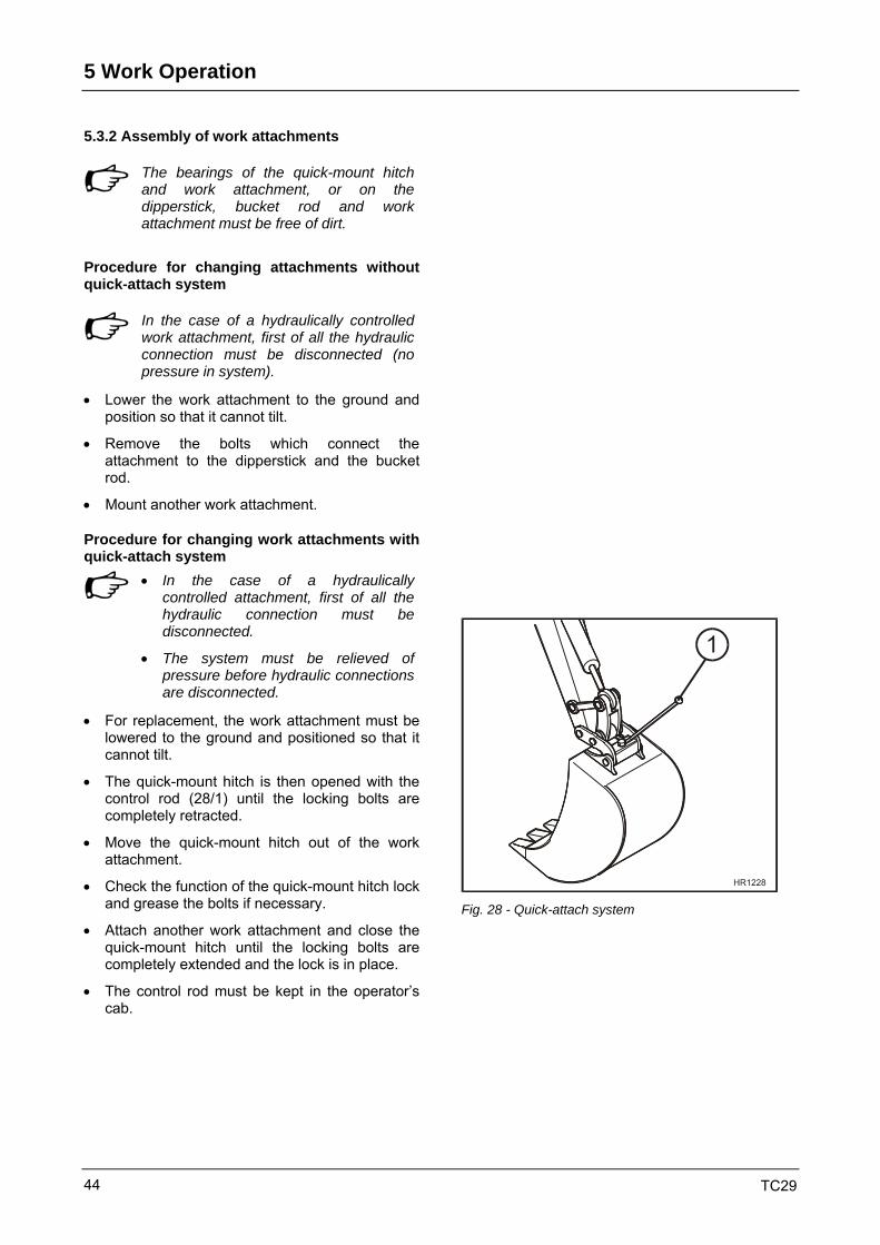
5 Work Operation
TC29 44
5.3.2 Assembly of work attachments
The bearings of the quick-mount hitch and work attachment, or on the dipperstick, bucket rod and work attachment must be free of dirt.
Procedure for changing attachments without quick-attach system
In the case of a hydraulically controlled work attachment, first of all the hydraulic connection must be disconnected (no pressure in system).
• Lower the work attachment to the ground and position so that it cannot tilt.
• Remove the bolts which connect the attachment to the dipperstick and the bucket rod.
• Mount another work attachment.
Procedure for changing work attachments with quick-attach system
• In the case of a hydraulically
controlled attachment, first of all the hydraulic connection must be disconnected.
• The system must be relieved of pressure before hydraulic connections are disconnected.
• For replacement, the work attachment must be lowered to the ground and positioned so that it cannot tilt.
• The quick-mount hitch is then opened with the control rod (28/1) until the locking bolts are completely retracted.
• Move the quick-mount hitch out of the work attachment.
• Check the function of the quick-mount hitch lock and grease the bolts if necessary.
• Attach another work attachment and close the quick-mount hitch until the locking bolts are completely extended and the lock is in place.
• The control rod must be kept in the operator’s cab.
Fig. 28 - Quick-attach system

Work Operation 5
TC29 45
Hydraulic quick-attach system HS03 - Option
• Two-handed operation (safety switching) is required to operate this.
• Press the button toggle switch (28a/14) on the left joystick with your left hand.
Opening the quick-attach system • Press and hold the button toggle switch
(28a/14) on the left joystick. At the same time, pull the dozer blade lever (28a/8) back and lift the dozer blade as far as it will go.
• The locking pin on the quick-attach system unlocks.
• The work attachment can be attached.
Closing the quick-attach system • Release the button toggle switch (28a/14) on
the left joystick.
• The locking pin on the quick-attach system locks.
• The work attachment is attached.
• If the button toggle switch (28a/14) is not pressed, the quick-attach system is locked by means of spring force.
Fig. 28a - Hydraulic quick-attach system
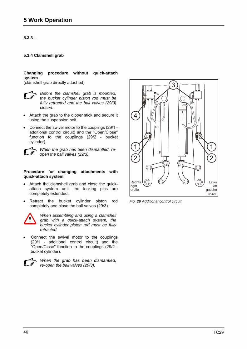
5 Work Operation
TC29 46
5.3.3 --
5.3.4 Clamshell grab
Changing procedure without quick-attach system (clamshell grab directly attached)
Before the clamshell grab is mounted, the bucket cylinder piston rod must be fully retracted and the ball valves (29/3) closed.
• Attach the grab to the dipper stick and secure it using the suspension bolt.
• Connect the swivel motor to the couplings (29/1 - additional control circuit) and the "Open/Close" function to the couplings (29/2 - bucket cylinder).
When the grab has been dismantled, re-open the ball valves (29/3).
Procedure for changing attachments with quick-attach system
• Attach the clamshell grab and close the quick-attach system until the locking pins are completely extended.
• Retract the bucket cylinder piston rod completely and close the ball valves (29/3).
When assembling and using a clamshell grab with a quick-attach system, the bucket cylinder piston rod must be fully retracted.
• Connect the swivel motor to the couplings (29/1 - additional control circuit) and the "Open/Close" function to the couplings (29/2 - bucket cylinder).
When the grab has been dismantled, re-open the ball valves (29/3).
Fig. 29 Additional control circuit

Work Operation 5
TC29 47
5.3.5 Hydraulic rock breaker
Attachment
Only the rock breakers approved by Terex are to be used.
The mounting and operating instructions of the hydraulic rock breaker manufacturer must be observed! The hydraulic circuit of the rock breaker must be secured according to the instructions of the hydraulic rock breaker manufacturer. When working in or under water, special rock breaker types must be used.
• The hydraulic rock breaker is mechanically attached in the same manner as a bucket attachment with or without quick-attach system.
• The hydraulic pressure supply is connected to a line of the additional control circuit (29/1) by a coupling.
• The return must be connected to the coupling (29/4) of the "open return".
Working with the hydraulic rock breaker The mounting and operating instructions of the hydraulic rock breaker manufacturer must be observed!
Improper use may lead to severe damage to the rock breaker, holder and the excavator itself.
Maintenance The maintenance of the hydraulic rock breaker must be performed according to the instructions of the hydraulic rock breaker manufacturer.
Fig. 29-Additional control circuit

5 Work Operation
TC29 48
5.4 Dismounting the cab
For some applications, it is favorable to work without cab.
In order to dismount the cab and to install the canopy, the original Terex crane lifting beam has to be used.
Weight of the cab approx. 150 kg
If the excavator is used without a cab, the canopy has to be mounted as a protection against falling objects.
Dismounting the cab • Open both cab doors and click them in support.
• Remove the cover from the right-hand side of the seat console and disconnect the electrical connection for the windshield wiper.
• Remove the covers on the rear right and left-hand sides of the cab.
• Screw the crane lifting beam onto the cab using 4 bolts.
• Remove fastening screws (31/1-4 pc.) and washers (31/2) and nuts (31/5-2 pc.).
• Unhinge the cab using a crane and place it carefully down the ground.
• Re-install the covers on the rear right and left-hand sides in the cab.
• Check the condition and correct seat of the seal rubber (31/4). Fit the washers (31/3) onto the fastening holes.
• Install the canopy and attach it using the two center socket pins as supports.
Tightening torque: MA = 80 Nm.
• Insert the plug for working floodlights on the right-hand side next to the seat console and screw on the cover.
Dismount the canopy and re-mount the cab in the same manner as above but in reverse order.
Fig. 31- Attachment of cab
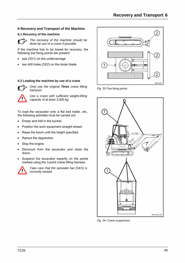
Recovery and Transport 6
TC29 49
6 Recovery and Transport of the Machine 6.1 Recovery of the machine
The recovery of the machine should be done by use of a crane if possible.
If the machine has to be towed for recovery, the following tow fixing points are present:
• eye (33/1) on the undercarriage
• two drill holes (33/2) on the dozer blade
6.2 Loading the machine by use of a crane
Only use the original Terex crane lifting harness!
Use a crane with sufficient weight-lifting capacity of at least 3,000 kg.
To load the excavator onto a flat bed trailer, etc., the following activities must be carried out:
• Empty and fold in the bucket.
• Position the work equipment straight ahead.
• Raise the boom until the height specified.
• Retract the dipperstick.
• Stop the engine.
• Dismount from the excavator and close the doors.
• Suspend the excavator expertly on the points marked using the 3-point crane lifting harness.
Take care that the spreader bar (34/1) is correctly seated.
HR1433
1
2
2
2
Fig. 33-Tow fixing points
HR14-03-34
1
1
ca.310
ca.1300
Fig. 34- Crane suspension

6 Recovery and Transport
TC29 50
6.3 Transport of the machine
• When transporting the machine on trucks, flatbed trailers, or by rail, it must be properly lashed at the marked points (undercarriage 35/1 and dozer blade 35/2) and secured with chocks.
• To do so, lower the dozer blade and position the work equipment on the ground.
Be aware of the total transport height.
Risk of accident when driving in tunnels, under bridges, etc.!
Loading the machine onto a truck
• The machine can be loaded using ramps with an angle of up to 15°.
• Secure the vehicle to be loaded with wedges to prevent it rolling away.
• Drive the machine in reverse onto the vehicle and drive it forward when unloading it from the truck.
• Lower the dozer blade and place the working equipment on the ground.
• Lash down the machine for transport.
HR1435
2
2
1
1
1
1
Fig. 35-Lashing
HR14-03-36 Fig. 36-Loading onto a truck

Care and Maintenance 7
TC29 51
7 Care and Maintenance
7.1 General notes
The good operating condition and life expectancy of machines are largely influenced by care and maintenance.
For this reason, it is in every machine owner’s interest to perform the specified maintenance work and comply with the service intervals. This Section deals in detail with periodic maintenance, inspection and lubricating tasks.
The type-specific maintenance and inspection plan lists all work to be performed on the machine at regular intervals. Maintenance and inspection plans for this purpose are contained in every instruction book.
It is essential that the recommendations in Chapter 2, "Safety and Prevention of Accidents" are observed.
7.2 Intervals
First inspection once before first putting into operation Chapter 7.8.1
Daily jobs every 10 op. h* or every work shift 1) Chapter 7.8.2
Weekly jobs weekly or after 50 op. h* 1) Chapter 7.8.2
100 operating hours once after first putting into operation 2) Chapter 7.8.4
Every 500 operating hours after every 500 operating hours Chapter 7.8.4
Every 1000 operating hours after every 1000 operating hours Chapter 7.8.4
1) whichever comes first 2) also applicable when new or overhauled diesel engines are put into operation

7 Care and Maintenance
TC29 52
7.3 Regular oil analyses
Oil analyses are not intended as a substitute for the oil change intervals but – apart from a possible reduction of maintenance costs and as a form of preventive maintenance – they take into account the increasing environmental awareness.
Advantages of an oil analysis
• Extension of the oil change intervals under standard or light-duty operating conditions.
• Minimum wear of high-quality components with optimum use of the lubricants.
• Periodic laboratory analyses enable an early detection of imminent damage.
• Repairs performed before they actually become absolutely necessary help prevent serious and unexpected damage.
• Sequential damage can be avoided.
Oil analysis intervals
Periodic oil analyses reveal trends in the condition of the oil and the machine.
When the scheduled oil change intervals have been reached, the oils should be analyzed in the following intervals to check their quality and thus extend the oil change intervals:
• Hydraulic oil: 1,000 operating hours
• Transmission oil: 500 operating hours
• Engine oil: 100 operating hours
Based on the first results, the laboratory recommends the interval for the next sampling.
Ask your Terex dealer for an information booklet detailing the scope and procedures of the oil analysis.
7.4 Warranty
During the warranty period thorough inspections are stipulated, which must be carried out by trained specialist dealer personnel.
The inspections are obligatory and must be paid for.
The performance of inspections as specified must be confirmed on the inspection cards in the warranty / handing over certificate.
If they are omitted, the warranty may be subject to restrictions.

Care and Maintenance 7
TC29 53
7.5 Inspection parts and aids
Maintenance and wearing parts for inspection should be ordered well in advance! Contact your dealer!
Lubricants
• The machine’s life expectancy and operating condition are largely dependent upon the use of the specified lubricants and compliance with the service intervals.
• If lubricants which do not conform to our recommendations are used, consequential damage may occur for which we will not assume liability, even inside the warranty period.
• For lubricant specifications see "Technical Data", Chapter 3.6.2.

7 Care and Maintenance
TC29 54
7.6 Care and cleaning
The machine must be cleaned on a suitable surface with an oil separator.
• Neither a steam-jet appliance nor a high-pressure cleaning apparatus may be used for cleaning during the first two months after the machine is used for the first time or when newly painted to ensure that the paint can sufficiently harden.
• Do not use aggressive detergents for cleaning the machine. We recommend using commercially available cleaning agents for passenger cars.
• When cleaning with a steam-jet appliance, the hot water jet should not exceed 80°C and a spray pressure of 70 bar.
• Linings (insulating materials, etc.) shall not be exposed directly to water, steam or high-pressure jets.
• When cleaning with water or steam jets, take care not to spray exhaust-gas and air filter openings.
• If cleaning the engine with water or steam jets, do not expose sensitive engine parts, such as generator, cabling, oil pressure switch, etc. directly to the jet.
• After each wet clean, the machine must be lubricated in accordance with the lubricating plan and a test of all work cycles, support and driving functions carried out.
7.7 Notes for winter operation
The following points - and the relevant notes in the engine instruction book - should be observed during winter operation.
Hydraulic oil
• If the machine is not used for longer periods at temperatures around and below freezing, warm up the engine by running at medium revs (for approx. 3-5 min).
Engine oil
• The oil viscosity (SAE class) should be selected according to the ambient temperature at the machine’s place of operation.
Coolant
• Before the beginning of the cold season, check the level of antifreeze and adjust in line with the ambient temperature if necessary.
• At the factory, the antifreeze protection is set to approx. -40°C.
Battery charge
• A good cold start performance requires a well-charged battery. By warming the battery to approx. +20°C (remove the battery after the engine has been turned off and store it in a warm room), the minimum starting temperatures can be lowered by 4-5°C.
• When installing the battery, ensure good contact of terminal connections.
• Only tighten terminal screws so that they are "hand-tight", to prevent deformation of the terminal cones!
Fuel
• Only use commercially available brand-name diesel fuel with a sulfur content of less than 0.5 %.
• Use only winter diesel fuel in winter, in order to prevent cables becoming blocked through paraffin deposits. At very low temperatures, troublesome deposits may also occur when winter diesel is used.

Care and Maintenance 7
TC29 55
7.8 Checking, maintenance and inspection plans
7.8.1 Initial inspection (delivery/ handing-over inspection)
HR14-03-41
2 43 5 867 Fig. 41 Initial inspection
Jobs to be carried out by trained specialist dealer personnel.
Chapter
1 Check whether machine-specific instruction book is in the machine --
2 Check engine oil level 7.9.1
3 Check hydraulic oil level 7.9.8
4 Check fuel level 7.9.4
5 Check coolant level 7.9.3
6 Oil check: crawler gear units 7.9.12
7 Check crawler chain tension 7.9.14
8 Battery: fluid level and charge condition 7.9.18
9 Grease machine (all lubricating points) 7.8.3
10 Test run, hydraulic function check and test work --
11 Visual inspection for tightness of all hoses, pipes, cylinders, etc. --
12 Check function of electrical indicating and warning elements, and the lighting system --
13 Initial delivery/ handing-over certificate and return to manufacturer --
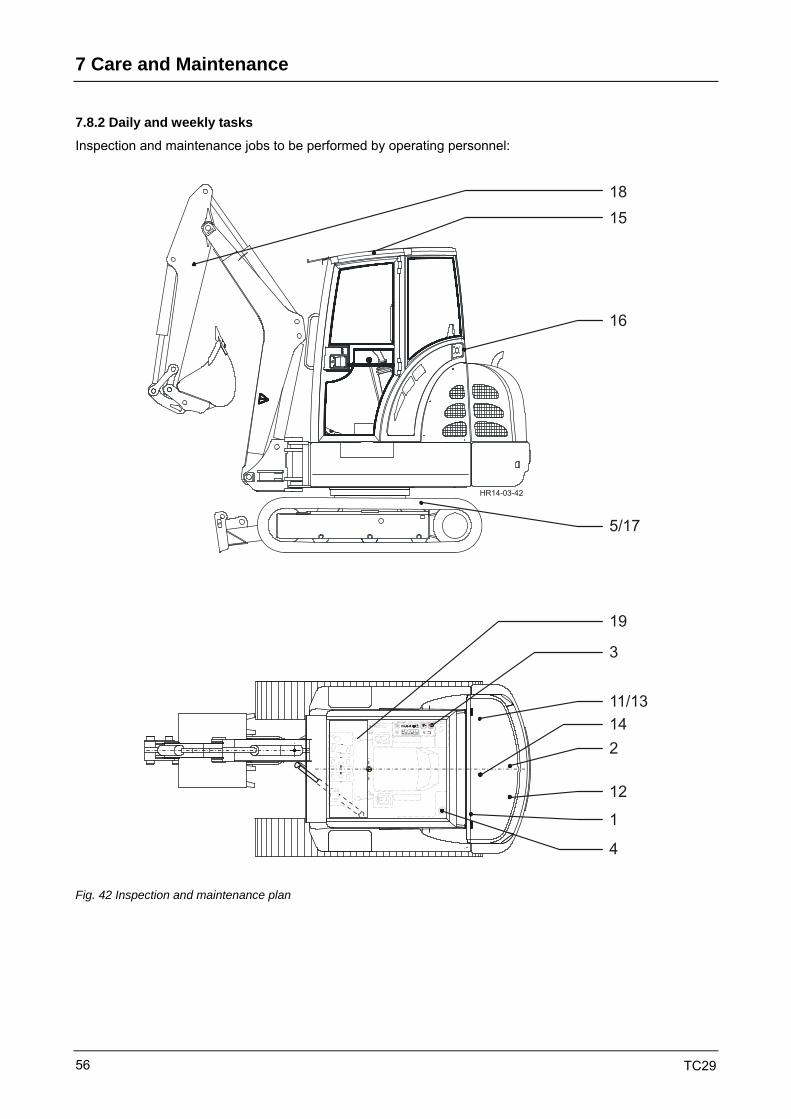
7 Care and Maintenance
TC29 56
7.8.2 Daily and weekly tasks
Inspection and maintenance jobs to be performed by operating personnel:
HR14-03-42
1815
16
5/17
21411/13
12
1
4
3
19
Fig. 42 Inspection and maintenance plan

Care and Maintenance 7
TC29 57
Daily Chapter
1 Check hydraulic oil level 7.9.8
2 Check engine oil level 7.9.1
3 Check fuel level (fuel gauge on instrument panel) 7.9.4
4 Check water level for windshield wiper 7.9.17
5 Check the crawler chain tension of the rubber crawlers 7.9.14
6 General visual inspection for material cracks, external damage, completeness, etc. --
7 Check for leaks in: pipes, hoses, control valve, hydraulic pumps, cylinders, etc.
--
When tightening hose and line connections, the screw-in couplings must be locked to prevent rotation.
8 Check electrical indicating and warning elements, and the lighting system --
9 Check smooth running of operator controls --
10 Grease machine in compliance with overview of lubricating points 7.8.3
Weekly Chapter
11 Clean cooling fins of the water cooler and the hydraulic oil cooler 7.9.3
The cleaning intervals should be shortened if there is high exposure to dust! 7.9.9
12 Check if there is water and/or dirt in the fuel line water separator and clean if required. 7.9.4
13 Check coolant level 7.9.3
14 Clean dust ejection valve on air filter 7.9.5
The cleaning intervals should be shortened if there is high exposure to dust!
15 Check the function of the front window --
16 Check that door catches function perfectly --
17 Check the crawler chain tension of the steel crawlers 7.9.14
18 Check bearing bushings and bolts of the work equipment --
19 Check function, condition and completeness of safety devices, e.g. exit barrier, etc. --
20 Grease machine in compliance with overview of lubricating points 7.8.3

7 Care and Maintenance
TC29 58
7.8.3 Overview of lubricating points
Replace damaged grease nipples immediately and check if grease passes through!
HR14-03-43
+- 0 4/4
12
3
4
5
6
7 8 9
10
11
12
1314 19
18
15 16
12
3
21
20
17
25
Fig. 43 Lubrication plan

Care and Maintenance 7
TC29 59
Grease all lubricating points with multi-purpose grease.
T h e i n t e r v a l s s t a t e d a r e v a l i d f o r o n e - s h i f t o p e r a t i o n
Item Lubricating point Qty. daily weekly Chapter
1 Bucket rod - Bucket (quick-mount hitch) 1 X --
2 Dipperstick - Bucket (quick-mount hitch) 1 X --
3 Bucket cylinder - bucket rod - tilt lever 3 X --
4 Dipperstick - Tilt lever 1 X --
5 Bucket cylinder - Dipperstick 1 X --
6 Dipperstick cylinder - Dipperstick 1 X --
7 Boom - Dipperstick 1 X --
8 Dipperstick cylinder - Boom 1 X --
9 Boom cylinder - Boom 1 X --
10 Boom cylinder - Slewing column 1 X --
11 Slewing column - Boom 1 X --
12 Articulated cylinder - Slewing column 1 X --
13 Uppercarriage - Slewing column 2 X --
14 Dozer blade cylinder 2 X --
15 Dozer blade control lever 1 X --
16 Ring gear - bearing system 2 X 7.9.15
17 Ring gear - toothing (open lateral lid, left-hand side) 1 X 7.9.15
18 Uppercarriage articulated cylinder (open lateral lid, left-hand side)
1 X --
19 Engine hood hinges 2 X --
20 Door hinges 4 X --
21 Quick-mount hitch 2 X --
For lubrication, place the bucket on the ground, open the quick-mount hitch - the bolts must be fully retracted - and start to lubricate. Close quick-mount hitch.
Non-standard equipment
25 Clamshell grab 11 X --
We recommend that for special operations, e.g. on sandy ground, the lubrication intervals are shortened. Increased frequency of lubrication helps self-cleaning of bearing points.

7 Care and Maintenance
TC29 60
7.8.4 Inspection plan
To be carried out by trained dealer personnel.
O = Checking, maintenance X = Replacement
Operating hours
min. 2x
min. 1x
Perform work with machine at operating temperature after 100
every500
every 1,000
yearly yearly Chapter
1 Check whether machine-specific instruction book is in the machine
O O --
2 Change engine oil X X X 7.9.1
3 Change engine oil filter X X X 7.9.2
4 Drain water from fuel tank O O O 7.9.4
5 Change fuel filter X X X 7.9.4
6 Check air intake O O 7.9.5
7 Change air filter - main cartridge in compliance with service indicator
X 7.9.5
8 Change air filter - safety cartridge as required 1) 7.9.5
9 Clean cooling fins of hydraulic oil cooler O O O 7.9.9
The cleaning intervals should be shortened if there is high exposure to dust
10 Clean cooling fins of water cooler O O O 7.9.3
The cleaning intervals should be shortened if there is high exposure to dust
11 Check antifreeze level in coolant O 7.9.3
12 Change coolant as required 1) 7.9.3
13 Check V-belt tension O O 7.9.6
14 Check engine mounts and pump attachments O O --
15 Check engine speed adjustment, top-end and low-idle idle speed
O O --
16 Check valve lash of engine and adjust if necessary O O O 7.9.7
17 Check injection nozzles O --
18 Check injection pump O --
19 Check acid level and battery connections O O 7.9.18
20 Check condition of crawler chains O O 7.9.14
21 Check secure fastening of sprocket, crawler gear units and hydraulic motor
O O --
22 Check smooth running of bottom and top rollers O O
23 Check bearing bushings and bolts of work equipment and re-adjust "free of clearance"
O O --

Care and Maintenance 7
TC29 61
O = Checking, maintenance X = Replacement
Operating hours
min. 2x
min. 1x
Perform work with machine at operating temperature after 100
every500
every 1,000
yearly yearly Chapter
24 Check electrical indicating and warning elements, and lighting system
O O --
25 Check smooth running of operator controls and adjust if necessary
O O --
26 Check tightness of all pipes, hoses, control valve, hydraulic pumps, cylinders, etc.
O O --
When tightening hose and pipe connections, screw-in couplings must be locked to prevent rotation.
27 Check or change hydraulic oil O O X 2) X 7.9.8
28 Replace hydraulic oil return filter insert X X X 7.9.10
29 Replace breather X X 7.9.11
30 Crawler gear units: Check or replace oil X O X X 7.9.12
31 Check that swing gear unit is securely fastened O O O 7.9.15
32 Check that ring gear attachment screws are securely fastened
O O O 7.9.15
33 Grease machine in compliance with overview of lubricating points
O O 7.8.3
34 Check function, condition and completeness of safety equipment
O O --
35 Function of brake valves O O 7.9.13
36 Hydraulic function check with pressure function test O O --
37 Test run and test work O O --
38 Initial inspection card and return to manufacturer O O 3) 7.4
1) at least every 2 years
2) Extension of oil change interval in compliance with oil sample analysis and lab report For further information see Chapter 7.3
3) within warranty

7 Care and Maintenance
TC29 62
7.9 Inspection and maintenance work
7.9.1 Engine oil
Checking the engine oil level
• The oil level must be checked daily before start-up, with the machine standing on level ground.
• Move in the oil dipstick (46/3) until the stop. The notches on the dipstick indicate the minimum and maximum oil levels.
• Top up engine oil if necessary. Open the filler neck (46/2) and add oil using a clean container. Close the filler neck again.
Engine oil change
Collect the waste oil, do not allow it to seep into the ground.
Dispose of in compliance with regulations!
Oil change
• Run the engine until it reaches operating tem-perature, engine oil temperature approx. 80°C.
• Park the machine on a level surface.
• Switch off the engine.
• Place suitable drip pans below the opening.
• Screw the oil drain hose onto the oil-change valve (46/1).
Danger of scalding when hot oil is drained!
• Remove the oil drain hose and screw the protective cap onto the valve (46/1).
• Replace the engine oil filter (see 7.9.2).
• Fill up with engine oil via the filler neck (46/2) to the "MAX" mark on the dipstick (46/3).
• Start the engine and run at low idle speed for approx. 2 min.
• Switch off the engine.
• Check the oil level, top up if necessary.
HR14-03-46
3
2
1
4
Fig. 46 Engine oil

Care and Maintenance 7
TC29 63
7.9.2 Engine oil filter
The engine oil filter must be replaced every time the engine oil is changed.
• Unscrew the filter cartridge (46/4) using a tightening scrap wrench or similar tool and dispose of in compliance with regulations.
• Clean the filter head and check its condition.
• Fill the new filter with oil, wet the seal ring with oil and tighten firmly by hand.
• Check the tightness of the engine oil filter cartridge.
7.9.3 Engine - Cooling system
Coolant level
Only check when the engine is cold. Danger of scalding from hot coolant!
• Remove the cap (47/1) and check the water level.
• The water level must be up to the overflow pipe (47/2).
Top up with a mixture of 50% water and 50% antifreeze.
Water cooler - Cleaning cooling fins
Dirt accumulation in coolers causes the engine to overheat.
• Clean the water cooler from the outlet side with compressed air.
• If necessary, e.g. if there is oil in the cooler, clean with cold cleaner or a steam jet appliance.
When cleaning with the aid of a steam jet appliance, the cleaning area must be equipped with an oil separator.
After cleaning, run the engine until it reaches operating temperature, to dry the cooler.
HR14-03-46
3
2
1
4
Fig. 46 Engine oil
1
2
HR14-03-47 Fig. 47 Water cooler

7 Care and Maintenance
TC29 64
Changing coolant
Only change coolant when the engine is cold.
Danger of scalding from hot coolant!
• Park the machine on level ground.
• Place drip pan below the engine and the cooler.
• Remove the cooler cap.
• Open the drain valve (48/1) on the cooler and drain coolant.
• Remove the water drain plug (48/2) from the cylinder block and drain coolant.
• Flush the cooling system with clean water if necessary.
• Re-fit the drain plug to the engine and close the drain valve on the cooler.
• Fill the cooling system with coolant and close the cooler with the cap (47/1).
• Start the engine and bring to operating temperature, then turn off and allow to cool.
• Check the coolant level and top up (several times, if necessary).
1
2
HR14-03-47 Fig. 47 Water cooler
HR14-03-48
1
2
Fig. 48 Coolant change

Care and Maintenance 7
TC29 65
7.9.4 Fuel tank
Checking the fuel level
• Check the fuel level using the fuel gauge (49/23).
• In order to prevent condensation from forming before the machine is next put into operation, top up the fuel every day after use (50/1).
Collect fuel when working on the fuel system!
TC35-03-49
23
Fig. 49 Operation
1
HR14-03-50 Fig. 50 Fuel tank

7 Care and Maintenance
TC29 66
Fuel filter
• Loosen hose clamps (51/2), remove filter (51/1).
• Collect any escaping fuel.
• Mount new fuel filter and re-tighten hose clamps.
• Check tightness.
Venting the fuel system is not necessary.
Cleaning the water separator
• Clean according to the ring (52/3).
• Close the shut-off valve (52/1) on the water separator.
• Unscrew the bottom part (52/2), clean the housing and the filter insert.
• Check if the filter insert is damaged and replace if necessary.
• Re-assemble the water separator and open the shut-off valve.
Fuel tank
• Drain water from the fuel tank through the drain plug.
• Clean the filling strainer and check for damage.
• Replace if necessary.
HR14-03-51
1
2
Fig. 51-Fuel filter
Fig. 52-Water separator

Care and Maintenance 7
TC29 67
7.9.5 Air filter, air intake
All maintenance work on the air intake system must be carried out with the engine off.
Do not start the engine while the filter cartridge is removed.
7.9.5.1 Dust ejection valve
• The dust ejection valve (53/1) is largely maintenance-free.
• Any baked-on dust can be removed by squeezing the valve together.
7.9.5.2 Air intake
• Clean impurities (leaves, etc.) from the air intake section before the air filter.
• Check the air filter attachment for damage and repair or replace, if necessary.
• Check the tightness of the air duct after the air filter.
• Examine rubber parts for damage.
Replace damaged parts immediately.
7.9.5.3 Cartridge maintenance interval
Air filter - main cartridge
• The air filter main cartridge must be replaced when, during operation, the filter clogging indicator lamp (54/21) in the instrument panel lights up, actuated by the service switch.
• A brief delay in maintenance does not result in lower filter efficiency.
Air filter - safety cartridge
The air filter - safety cartridge must be replaced in the following cases:
• after the third maintenance of the main cartridge
• when it has reached the maximum service life of two years
• if the service indicator switches on after maintenance of the main cartridge has just been performed
• if the main cartridge is damaged
• if the safety cartridge is damaged
1HR12-03-53
Fig. 53-Air filter
TC35-03-54
21
Fig. 54-Operation

7 Care and Maintenance
TC29 68
7.9.5.4 Cartridge replacement
Main cartridge
• Open the tension brackets (55/5) and remove the cover (55/1) along with the dust ejection valve.
• Withdraw the dirty air filter cartridge (55/2) by carefully turning and tilting and dispose of it.
• Note down the date of maintenance in the appropriate sections of the safety cartridge.
• Clean the filter housing (55/4), especially the seal area for the air filter cartridge, with a damp cloth.
• Check if new air filter cartridge is damaged.
Do not mount damaged air filter cartridges as this may result in damage to the diesel engine.
• Mount the air filter cartridge into the filter housing by slightly turning.
• Mount cover with dust ejection valve to the bottom side and fasten with tension brackets (55/5).
Safety cartridge
• Remove the main cartridge.
• Remove the safety cartridge (55/3) by carefully turning and tilting and dispose of it.
• Clean the filter housing, especially the seal area for the cartridges, with a damp cloth.
• Mount new safety cartridge into the filter housing by slightly turning it.
• Mount main cartridge into the filter housing.
• Mount cover with dust ejection valve to the bottom side and fasten with tension brackets (55/5).
Fig. 55-Air filter cartridge replacement

Care and Maintenance 7
TC29 69
7.9.6 V-belts
Only check and tension V-belts with the engine off!
Danger of injury!
Check the complete V-belts and make sure that they are not damaged.
Replace worn or damaged V-belts immediately.
Checking the V-belt tension
In order to check the V-belt tension, a V-belt tensioning device is recommended. Check the tension in compliance with the manufacturer’s operating instructions.
Checking the V-belt tension without a tensioning device
• To check the tension, press the V-belt with your thumb in the middle of the greatest free length, and measure the sag of the V-belt.
• Using medium thumb pressure of approx. 45 N, the V-belt sag should equal 13 mm.
Tensioning V-belts
• Stop the engine and remove ignition keys.
• Open the engine hood.
• Slacken the fastening screws (56/1) of the generator.
• Rotate the generator until the tension is correct.
• Re-tighten the fastening screws (56/1 and 56/2) of the generator.
• Check the tension once more.
• Close the engine hood.
1
2
HR14-03-56
13 mm
14Nm
22Nm
Fig. 56 V-belt

7 Care and Maintenance
TC29 70
Replacing V-belts
• Open the engine hood.
• Disconnect the battery.
• Loosen the 2 fastening screws of the grill and remove the grill.
• Loosen the clamping bolt (56/1) of the generator and remove the V-belt.
• Slightly press the water cooler to the right and take out the V-belt above the fan blade.
• Mount new V-belt and tighten in compliance with instructions.
• Re-mount the 2 fastening screws of the grill.
• Re-connect battery.
• Check the correct function of the fan blade.
• Test run.
When new V-belts are fitted, their tension must be checked and adjusted if necessary after the first 15 min.
1
2
HR14-03-56
13 mm
14Nm
22Nm
Fig. 56 V-belt

Care and Maintenance 7
TC29 71
7.9.7 Valve lash
• The valve lash (57/1) is tested with the engine cold, by placing a reed gauge between the upper part of the tappet (57/3) and the rocker arm (57/2).
• The correct valve lash is as follows:
Inlet valve = 0.25 mm
Exhaust valve = 0.25 mm
Cylinder no. 1 is located on the front side of the engine breather. Firing sequence: 1 - 3 – 4 - 2
• Remove the valve cover.
• Turn the crankshaft clockwise until the valves intersect at cylinder no. 1.
• The marking (57/6) on the housing and V-belt pulley must be identical. Check the overlapping of the valve by moving the crankshaft by approx. 20° in both directions. The rocker arm must not move.
• If the rocker arm moves, the crankshaft must be turned further by one full turn (360°).
• In this position, check the valve lash of the valves on cylinder no. 1.
If necessary, adjust the valve lash as follows:
⇒ Slacken the lock nut (57/4).
⇒ Using a screwdriver, adjust the setting screw (57/5) in such a way that the correct valve lash (57/1) is obtained when the lock nut is tightened.
• To adjust the other cylinders, turn the crankshaft further by 180° each time. Order of adjustment = Firing sequence
• Check and adjust the valves in the same manner as for cylinder no. 1.
• Re-fit the valve cover.
Fig. 57-Valve lash

7 Care and Maintenance
TC29 72
7.9.8 Hydraulic oil tank
Checking the hydraulic oil level
• Check the oil level using the sight glass (60/3). Top up hydraulic oil if required.
• To do so, remove the return filter cap (60/2).
To check the hydraulic oil level, the excavating equipment must be extended and lowered to the ground. The hydraulic oil level must lie between the two markings.
Hydraulic oil change
Change the hydraulic oil when it is at operating temperature.
• Retract all hydraulic cylinders.
• Stop the engine.
• Unscrew the breather (60/1).
• Place suitable oil drip pans below the outlet.
Danger of scalding when hot oil is drained.
• Unscrew the drain plug (60/4) from the hydraulic oil tank and drain oil into clean containers.
Collect waste oil, do not allow it to seep into the ground.
Dispose of in compliance with regulations!
• Flush and clean the hydraulic oil tank as required. To do so, remove the cover (60/5 — cab and seat frame have to be dismounted).
• Screw on the drain plug carefully.
• Loosen the return filter cap.
• Fill up with clean hydraulic oil until the correct level on the sight glass (60/3) is reached.
• Re-mount the filter cover.
• Screw back in the breather.
34
15
2
HR14-03-60 Fig. 60-Hydraulic oil tank

Care and Maintenance 7
TC29 73
7.9.9 Hydraulic oil cooler
Dirt accumulation in coolers causes the hydraulic oil to overheat.
• The hydraulic oil cooler (61/1) is cleaned from the outlet side with compressed air.
• If necessary, e.g. if there is oil in the cooler, clean with cold cleaner or a steam jet appliance.
When cleaning with the aid of a steam jet appliance, the cleaning area must be equipped with an oil separator.
• After cleaning, run the engine until it reaches operating temperature in order to dry the cooler.
1
HR14-03-61 Fig. 61 Hydraulic oil cooler

7 Care and Maintenance
TC29 74
7.9.10 Hydraulic oil return filter
After a larger repair job, following the test run the filter insert must also be renewed.
Damaged hydraulic attachments may shorten the operating life of the return filter.
Replacing the filter insert
• Stop the engine.
Always place a receptacle for the collection of waste oil under the working area when removing the filter insert!
• Open the drain plug (63/6) and empty the dirty side of the filter.
• Remove the cap (63/1) of the return filter (62/2) using an auxiliary tool and screw off, paying attention to the O-ring (63/2) and the spring (63/3).
• Pull out the filter element (63/4) and dispose of in compliance with regulations.
• Clean the filter bowl if required.
• Check O-rings (63/2; 63/5) and replace any damaged parts.
• Check the condition of the fouling indicating sensor (63/7).
• Screw back in the drain plug (63/6).
• Insert a new filter element.
• Apply a light coat of grease to the cover seal and tighten the cover by hand.
• Check the tightness of the filter.
7.9.11 Breather
• Remove the breather (62/1), replace by a new filter and tighten so that it is hand-tight.
The breather must also be replaced if it is dirty, e.g. due to hydraulic oil vapor.
12
HR14-03-62 Fig. 62-Hydraulic oil tank
1
2
7
4
5
3
6
HR1462 Fig. 63-Return filter

Care and Maintenance 7
TC29 75
7.9.12 Crawler gear units
Checking the oil level
• Move the crawler unit to inspection position.
• Remove the inspection plugs (64/2) and top up oil up to bottom edge of the drill holes if required.
Oil change
Collect the waste oil, do not allow it to seep into the ground.
Dispose of in compliance with regulations!
• The oil must be changed at operating temperature with the machine parked on level ground.
• Position the gear in such a way that the drain plug (64/1) is completely at the bottom.
• Open the filler/ inspection plug (64/2) on the gear.
• Open the drain plug (64/1) and collect the oil.
• Flush out the gear with flushing oil if necessary.
• Carefully re-insert the drain plug with seal tape and top up transmission oil via the filler/ inspection plug (64/2) until oil escapes from the hole.
• Carefully re-insert the filler/ inspection plug with seal tape.
7.9.13 Brake valves
Function check
• Move both levers forward in a regular manner ("Machine rolling" position).
• Move both levers to neutral position at the same time. The machine should brake regularly and must not drift sideways.
Fig. 64-Crawler gear unit
Füll- und KontrollstellungFilling/Level
HR12-03-64
2
1
3
AblaßstellungDrain

7 Care and Maintenance
TC29 76
7.9.14 Crawler chains
Checking the crawler-chain tension
• The check has to be carried out on a level surface.
• Slew the uppercarriage by 90° and lift on one side until the crawler is free.
• The sag of the crawler between lower roller and crawler chain (Fig. 65-distance "a") should equal
approx. 25 – 35 mm (steel crawler chain)
approx. 15 – 20 mm (rubber crawler chain)
Tensioning the crawler chain
• Remove the cover on the right-hand and left-hand side of the crawler frame. Re-tension the crawler chain using the hand grease gun via the grease nipple (65/1).
• Move crawler chain and check the crawler-chain tension once more.
In the case of new rubber crawler chains, check the sag on the first day of operation 2 - 3 times and re-tension if necessary.
Releasing the crawler chain tension
When releasing the crawler chain tension, proceed with caution as grease may drain under pressure.
• In order to release the tension, slowly loosen the valve (65/2) with the grease nipple, let grease drain out until the crawler-chain tension is correct.
• Re-tighten the valve with the grease nipple.
• Remove grease and dispose of in compliance with regulations.
• Move the crawler chain and check the crawler-chain tension once more.
Fig. 65-Crawler-chain tension

Care and Maintenance 7
TC29 77
7.9.15 Swing bearing
Lubrication of toothing
• The grease nipple (66/1) mounted in the driver’s cab lubricates the toothing of the ring gear via a nozzle tube (66/2).
• To this purpose, slowly slew the uppercarriage and lubricate it thoroughly at the same time using a grease gun.
Lubrication of bearing races
• The bearing races are lubricated via the lubricating nipples (66/3) mounted on the ring gear.
• Slowly slew the uppercarriage, and lubricate it thoroughly until the gasket has a collar (66/4) of fresh grease.
Check secure fastening of swing bearing
When mounting for the first time, the screws must again be checked after 100 operating hours.
The following points are prerequisites for an optimum bolted connection on the undercarriage and the uppercarriage:
• The contact faces of bolts must be of bright metal, i.e. absolutely free from grease and paint.
• The thread and the bolt head shall not be damaged.
Damaged screws must be replaced by new ones!
All accessible screws must be examined to ensure that they are tightened to the torques specified in Figure 67.
Checking the swing gear attachment
All accessible screws must be examined to ensure that they are tightened to the torques specified in Figure 67.
A = uppercarriage
B = undercarriage
C = drill hole (x2) (below plastic plug)
HR14-03-66
4
243
1
Fig. 66-Ring gear
HR14-03-67
M = 115 NmA
M = 25 NmA
M = 290 NmA
M = 115 NmA
A
B
C
Fig. 67-Swing bearing

7 Care and Maintenance
TC29 78
7.9.16 Swing gear
The swing gear is maintenance-free. Circulation lubrication provided by the hydraulic system
7.9.17 Windshield washer
• Top up the washer fluid storage tank (69/13) as required.
• Add antifreeze when temperatures are around or below freezing.
HR14-03-69
3
Fig. 69 Washer fluid tank

Care and Maintenance 7
TC29 79
7.9.18 Electrical equipment
Battery
The battery is located below the right-hand side flap.
The instructions of the battery manufacturer must be observed when using the battery for the first time.
• The acid level should be approx. 10 mm above the edges of the plates. If necessary, top up with pure distilled water.
• Only check the battery with the engine off.
In the case of maintenance-free batteries, this check is not necessary.
Removing the battery
• Open the side flap.
• Disconnect first the battery ground cable, then the positive cable.
• Detach the clamping bracket (70/1).
• Lift out the battery.
Installing the battery
• Place the battery in the machine.
• Secure with the clamping bracket.
• First connect the positive cable, then the battery ground cable.
Ensure that the negative terminal is connected to the negative pole (-) and the positive terminal to the positive pole (+).
• Close the side flap.
In winter, in particular, the battery charge should be closely monitored.
Lighting and warning equipment
• Check the function of the lighting equipment.
• Check the function of the indicator lamps.
• Check the function of the warning equipment.
1
HR14-03-70 Fig. 70 Battery

7 Care and Maintenance
TC29 80
7.10 Shutdown
7.10.1 Preservation (temporary shutdown)
In order to prevent damage (corrosion, etc.) from storage during shutdown periods over three months, certain preservation measures must be taken:
• We recommend keeping the machine in a dry, dust-free room during the storage period.
• Clean the inside and outside of the machine, including the engine.
• Lubricate the machine in compliance with the lubrication plan.
• Check the oil levels of all assemblies, such as transmission (s), etc. and top up if necessary.
• Check the hydraulic oil level and top up if necessary.
• Repair paint damage.
• Fill the diesel tank completely, in order to prevent corrosion of the tank walls.
• Check the antifreeze level in the coolant and adjust if necessary.
• Perform all the preservation measures contained in the diesel engine operating instructions.
• Ensure that the crawler chain tension corresponds to the prescribed values and protect the rubber crawler chains from direct sunlight.
• Treat bare piston rods with a commercially available anti-corrosion agent.
• Remove and clean the battery and keep it in compliance with regulations in a dry - in winter, frost-proof - room. Coat connections with a little pole grease.
• Seal off the air intake opening of the air filter system and the exhaust pipe opening.
7.10.2 During shutdown
• When the machine is out of use for 6 months, after this time all assemblies must be brought to operating temperature and maneuvered for approx. 15 min.
• Beforehand, the anti-corrosion coat must be removed from the piston rods, and the openings of the air filter system and the exhaust pipe freed.
• After the maneuvering cycle, preserve the machine once more as previously described.
7.10.3 After shutdown
Before putting the machine into operation once more, the following measures must be carried out:
• Anti-corrosion coat must be cleaned from the piston rods.
• The openings of the air filter and exhaust pipe must be freed.
• Check the condition of the air filter main cartridge / safety cartridge and replace if required.
• Clean the machine with a neutral detergent.
• Check and - if required - re-charge and re-install the battery.
• Carry out all measures for putting the diesel engine back into operation stated in the engine operating instructions.
• If the machine has been out of use for more than 6 months, the oil in the assemblies such as transmission(s), etc. must be changed.
• If hydraulic oil filters (suction and return filters, and breathers - in so far as installed) have been out of use for more than 6 months, they must be replaced.
• Lubricate the machine in compliance with the lubrication plan.

Operating Problems 8
TC29 81
8 Operating problems 8.1 General
Operating problems are often the result of incorrect handling of the machine, the use of unsuitable materials or irregular maintenance.
The following table presents a summary of a range of problems and their probable causes.
If a problem can only be eliminated through repair, then the responsible Service Agent must be called in.
8.2 Engine
All faults in the diesel engine must be examined as described in the separate engine instruction book.
During the warranty period, malfunctions must be dealt with by the responsible SERVICE Agent or a specialist workshop.
Fault Possible cause Remedy 8.3 Machine is not driving
1 Engine damaged Check engine
2 Too little hydraulic oil in tank Top up hydraulic oil to recommended mark.
3 Hydraulic pump has failed Have pump checked for mechanical damage by a specialist. Replace complete hydraulic pump if necessary
4 Clutch or pump drive damaged Replace pump drive. Determine cause of damage.
5 Main pressure relief valve damaged or mis-adjusted
Replace main pressure relief valve
8.4 Insufficient travel power
1 Engine power insufficient Check diesel engine
2 Main pressure relief valves damaged or mis-adjusted
Check pressure, re-adjust valves, replace if necessary.
3 Oil loss in rotary transmission Re-seal rotary transmission.
4 Crawlers too tightly tensioned Check crawler-chain tension and reduce, if necessary

8 Operating Problems
TC29 82
Fault Possible cause Remedy 8.5 Excavator installation is not working
1 Exit barrier lifted or shutoff valve damaged Lower exit barrier and/or check shutoff valve or replace or repair if necessary.
2 Oil supply to hydraulic pump interrupted Check pipes.
3 Hydraulic pump has failed Have hydraulic pump checked by a specialist and replace, if necessary
4 Main pressure relief valves have failed or are mis-adjusted
Check main pressure relief valve and replace, if necessary
8.6 Decrease in machine’s performance
1 Insufficient engine power Check diesel engine.
2 Hydraulic oil level too low Top up hydraulic oil to the mark
3 Pump is sucking up air Tighten hose connections. Replace O-ring or seals
4 Insufficient operating pressure Re-adjust or replace main pressure relief valves
8.7 Machine is working too slowly and hydraulic oil is becoming too hot
1 Incorrect adjustment of main pressure relief valves, damaged valves
Re-adjust main pressure relief valves or replace if necessary
2 Hydraulic pump worn Replace hydraulic pump
3 Incorrect hydraulic oil Quality of hydraulic oil must conform to our recommendation
4 Oil level too low Top up oil to the mark on the sight glass
5 Oil cooler dirty or damaged Clean, check and replace if necessary
6 Air in hydraulic system Tighten connections with engine off and system relieved of pressure
8.8 Uppercarriage is slewing too far
1 Secondary valves damaged or mis-adjusted
Re-adjust secondary valves and replace if necessary
2 Swing motor is leaking - internal wear Replace hydraulic motor

Operating Problems 8
TC29 83
Fault Possible cause Remedy 8.9 Working cylinders are not working satisfactorily
1 Seals in cylinders worn Re-seal cylinders.
2 Secondary valves damaged or mis-adjusted
Check secondary valves and replace, if necessary.
3 Main pressure relief valves mis-adjusted. Check main pressure relief valves and replace if necessary.
8.10 Trouble in the electrical system
1 Outside and/or internal lighting without function
Check cables, connections, bulbs and fuses
2 Wiper does not function Check cables, connections and fuses. Examine wiper for mechanical damage, replace wiper motor if necessary
3 Windshield washer system does not function
Check water level. Check cables, connections and fuse. Check water pump and water pipes and replace if necessary.
4 Horn does not work Check cables, connections and fuses. Replace horn if necessary
5 Warning/indicating elements are imprecise
Determine the fault or source of the problem and eliminate it, call service personnel if necessary.
6 Starting system does not work satisfactorily
Check charge capacity of battery. Test starter function. Check connection and condition of power and battery ground cable. Check function of ignition lock, replace completely if necessary

8 Operating Problems
TC29 84

Appendix 9
TC29 85
9 Appendix 9.1 Electrical system
Fuse and relay box - Assignment diagram
4
K 1 K 2 K 3 K 4
TC29-35-48-04-E01K10
K12
Position Amps Assigned to
FB 60 A Pre-heating fuse
FA 30 A Main fuse
F1 5 A Instrument cluster 15, immobilizer
F2 10 A Fuel pump, generator
F3 15 A Working floodlights, front
F4 15 A Working floodlights, rear; boom
F5 10 A Travel slow/fast, travel motion alarm
F6 10 A Swing brake, dozer blade
F7 15 A Heater fan
F8 15 A Windscreen washer
F9 10 A Horn, radio 15
F10 10 A Option: 2nd control circuit, option: electrical seat
F11 5 A Instrument cluster 30, immobilizer 30
F12 10 A Interior light, radio 30, rotating beacon
F13 15 A Socket
F14 15 A Option: refueling pump option: 30
K1 -- Main relay terminal 15
K2 -- Relay for swing brake
K3 -- Optional
K4 -- Optional
K10 -- Glow plug timing unit
K12 -- Time relay, engine shut-off

9 Appendix
TC29 86
9.2 Immobilizer
The immobilizer may only be installed by the manufacturer of the machine or a qualified specialist workshop.
The certification of installation in accordance with specifications must be filled out by the manufacturer or the specialist workshop so that it can be submitted for insurance purposes.
You have installed a self-arming electronic immobilizer IS 900 safety stop, which works as follows:
• After the ignition has been switched off, the system automatically switches to the immobilization function after approx. 9 minutes. The green LED goes out and the red LED begins to flash for as long as the system is activated.
• If you want to start the vehicle, you must first enter your personal 4-digit code on the keypad. If the code has been entered correctly, the red LED goes out and the green LED lights up to indicate readiness to start. You must only enter the code when the ignition is switched off. If the pressure contact is correct, the green LED lights up.
• If the code is entered incorrectly, wait approx. 5 seconds before re-entering it.
• If 3 incorrect codes have been entered, the system is disabled for 8 minutes.
• Before leaving the machine in a workshop, you should enter a 6-digit code and inform the workshop personnel of this when you hand the key over. This code is retained until you enter your personal code again. The workshop code is then canceled automatically.
• Inform the workshop that when the workshop code applies, the system only arms itself after 30 minutes.
Coding:
The immobilizer installed in your vehicle has the following code, which has been applied at the factory: 0001
Entering or changing the personal code
(If the pressure contact is correct, the green LED lights up.)
No more than three identical numbers are accepted!
1. Enter the factory code "0-0-0-1" or your
personal code until the green LED lights up.
2. Immediately press "1" until the green LED flashes 4 times and goes out.
3. Now immediately enter the new code (e.g., "6-7-8-9") by pressing the numbers you have chosen in the correct sequence.
4. Immediately press "1" until the green LED flashes 4 times and goes out.
5. Immediately enter your personal code again.
6. Immediately press "1" until the green LED lights up.
7. The new code is now permanently programmed.

Appendix 9
TC29 87
Entering the workshop code
The workshop code must consist of 6 different numbers, e.g., "2-3-4-5-6-7"
1. Enter your personal code until the green LED
lights up.
2. Immediately press "1" until the green LED flashes 4 times and goes out.
3. Immediately press "2-3-4-5-6-7" (your workshop code).
4. Immediately press "1" until the green LED flashes 4 times and goes out.
5. Immediately press "2-3-4-5-6-7" (your workshop code) again.
6. Immediately press "1" until the green LED lights up.
This workshop code is automatically deleted when you enter your personal code again.
HR12-03-81
safty-stop1 2 3
4 5 6
7 8 9
0safty-stop
12
3
45
6
78
9
0
Fig. 81 - Immobilizer

9 Appendix
TC29 88

DELIVERY AND HANDING-OVER INSTRUCTIONS
The following checklist is to be adhered to when handing over the machine to the customer: 1. Operating instructions The operating instructions should be read side by side, and be explained in detail through practical training on the machine. The following items are of special importance: • Regulations for preventing accidents published by the employer’s
liability insurance associations in the user’s country • Technical data • Operator controls, control and warning indicators • Checks before putting the machine into operation • Specifications for diesel engine start-up • Switching on and off the diesel engine • Explanation of hydrostatic crawler drive • Travel operation • Recovery and transport of the machine • Operation of all functions • Tensioning the crawler chains • Explanation of maintenance and inspection intervals according to
Maintenance and Inspection Plan by demonstrating maintenance points on machine
• Lubrication intervals and points of lubrication according to overview of lubricating points and demonstration of these points on the machine
• Handing over the diesel engine operating instructions 2. Spare parts list • Structure of spare parts list, of figures and the respective descriptions • Instructions for ordering spare parts: always state the type of machine,
the vehicle identification number (Fz-Id.Nr.), parts designation, complete spare part number, piece number, delivery address, etc.
3. Warranty • Explanation of warranty covered by manufacturer • Explanation of inspection cards and note on maintenance and
inspection plan • The warranty/ handing-over card must be filled out correctly and sent
back
Crawler Excavator
TC29
Maintenance and Inspection Plan
The careful performance of all prescribed inspections is the best prerequisite for the machine’s continuous readiness for operation.
All maintenance work mentioned should therefore be performed in the prescribed sequence with the machine at operating temperature.
The inspections are obligatory.
If omitted, the warranty covered by us may be subject to restrictions.
The machine must be thoroughly cleaned before inspection takes place.
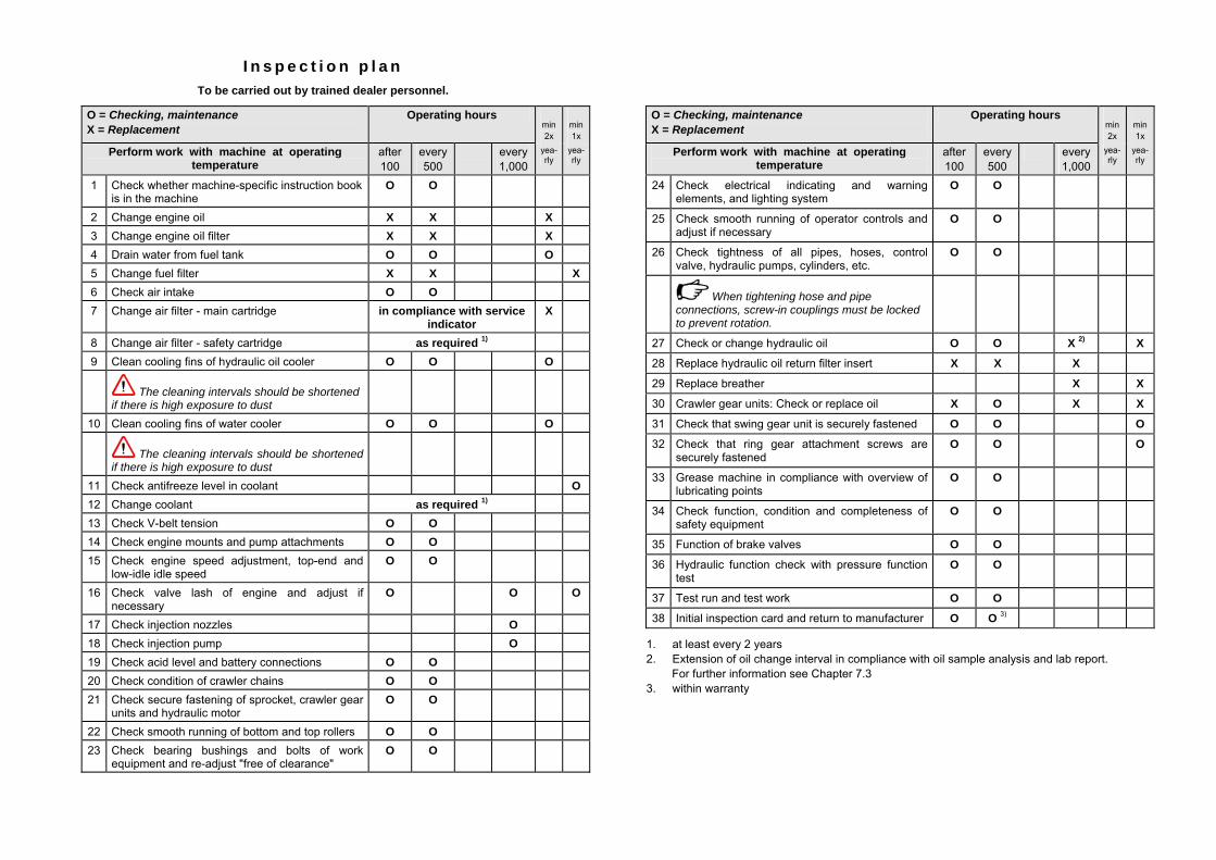
I n s p e c t i o n p l a nTo be carried out by trained dealer personnel.
O = Checking, maintenance X = Replacement
Operating hours min 2x
min 1x
Perform work with machine at operating temperature
after 100
every 500
every 1,000
yea-rly
yea-rly
1 Check whether machine-specific instruction book is in the machine
O O
2 Change engine oil X X X 3 Change engine oil filter X X X 4 Drain water from fuel tank O O O 5 Change fuel filter X X X 6 Check air intake O O 7 Change air filter - main cartridge in compliance with service
indicator X
8 Change air filter - safety cartridge as required 1) 9 Clean cooling fins of hydraulic oil cooler O O O
The cleaning intervals should be shortened if there is high exposure to dust
10 Clean cooling fins of water cooler O O O
The cleaning intervals should be shortened if there is high exposure to dust
11 Check antifreeze level in coolant O 12 Change coolant as required 1) 13 Check V-belt tension O O 14 Check engine mounts and pump attachments O O 15 Check engine speed adjustment, top-end and
low-idle idle speed O O
16 Check valve lash of engine and adjust if necessary
O O O
17 Check injection nozzles O 18 Check injection pump O 19 Check acid level and battery connections O O 20 Check condition of crawler chains O O 21 Check secure fastening of sprocket, crawler gear
units and hydraulic motor O O
22 Check smooth running of bottom and top rollers O O 23 Check bearing bushings and bolts of work
equipment and re-adjust "free of clearance" O O
O = Checking, maintenance X = Replacement
Operating hours min 2x
min 1x
Perform work with machine at operating temperature
after 100
every 500
every 1,000
yea-rly
yea-rly
24 Check electrical indicating and warning elements, and lighting system
O O
25 Check smooth running of operator controls and adjust if necessary
O O
26 Check tightness of all pipes, hoses, control valve, hydraulic pumps, cylinders, etc.
O O
When tightening hose and pipe
connections, screw-in couplings must be locked to prevent rotation.
27 Check or change hydraulic oil O O X 2) X
28 Replace hydraulic oil return filter insert X X X
29 Replace breather X X
30 Crawler gear units: Check or replace oil X O X X
31 Check that swing gear unit is securely fastened O O O
32 Check that ring gear attachment screws are securely fastened
O O O
33 Grease machine in compliance with overview of lubricating points
O O
34 Check function, condition and completeness of safety equipment
O O
35 Function of brake valves O O
36 Hydraulic function check with pressure function test
O O
37 Test run and test work O O
38 Initial inspection card and return to manufacturer O O 3)
1. at least every 2 years 2. Extension of oil change interval in compliance with oil sample analysis and lab report. For further information see Chapter 7.3 3. within warranty