Embed Size (px)
Citation preview
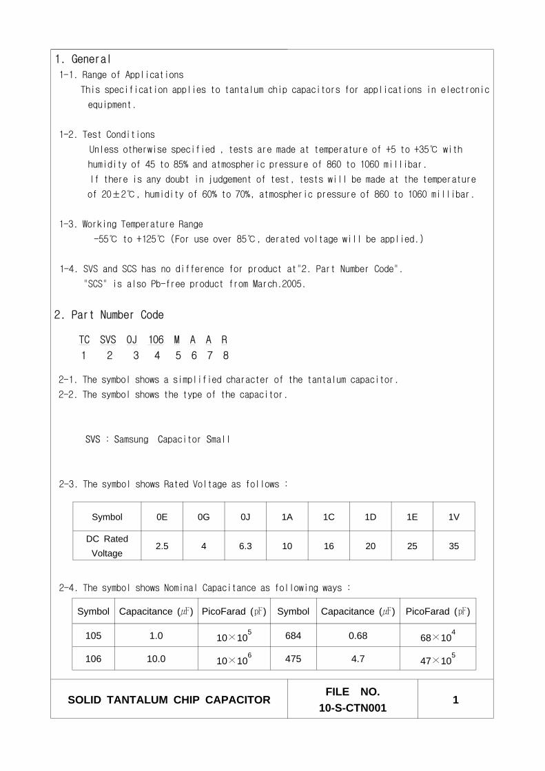
1. General
1-1. Range of Applications
This specification applies to tantalum chip capacitors for applications in electronic
equipment.
1-2. Test Conditions
Unless otherwise specified , tests are made at temperature of +5 to +35 with
humidity of 45 to 85% and atmospheric pressure of 860 to 1060 millibar.
If there is any doubt in judgement of test, tests will be made at the temperature
of 20±2, humidity of 60% to 70%, atmospheric pressure of 860 to 1060 millibar.
1-3. Working Temperature Range
-55 to +125 (For use over 85, derated voltage will be applied.)
1-4. SVS and SCS has no difference for product at"2. Part Number Code".
"SCS" is also Pb-free product from March.2005.
2. Part Number Code
TC SVS OJ 106 M A A R
1 2 3 4 5 6 7 8
2-1. The symbol shows a simplified character of the tantalum capacitor.
2-2. The symbol shows the type of the capacitor.
SVS : Samsung Capacitor Small
2-3. The symbol shows Rated Voltage as follows :
2-4. The symbol shows Nominal Capacitance as following ways :
SOLID TANTALUM CHIP CAPACITORFILE NO.
10-S-CTN0011
Symbol 0E 0G 0J 1A 1C 1D 1E 1V
DC RatedVoltage
2.5 4 6.3 10 16 20 25 35
Symbol Capacitance () PicoFarad () Symbol Capacitance () PicoFarad ()
105 1.0 10×105 684 0.68 68×10
4
106 10.0 10×106 475 4.7 47×10
5
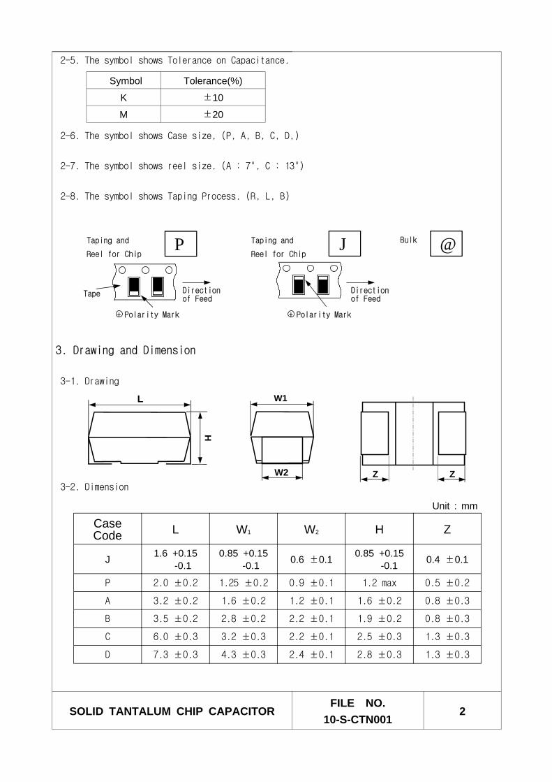
2-5. The symbol shows Tolerance on Capacitance.
2-6. The symbol shows Case size, (P, A, B, C, D,)
2-7. The symbol shows reel size. (A : 7", C : 13")
2-8. The symbol shows Taping Process. (R, L, B)
3. Drawing and Dimension
3-1. Drawing
3-2. Dimension
SOLID TANTALUM CHIP CAPACITORFILE NO.
10-S-CTN0012
CaseCode L W1 W2 H Z
J 1.6 +0.15-0.1
0.85 +0.15-0.1 0.6 ±0.1 0.85 +0.15
-0.1 0.4 ±0.1
P 2.0 ±0.2 1.25 ±0.2 0.9 ±0.1 1.2 max 0.5 ±0.2
A 3.2 ±0.2 1.6 ±0.2 1.2 ±0.1 1.6 ±0.2 0.8 ±0.3
B 3.5 ±0.2 2.8 ±0.2 2.2 ±0.1 1.9 ±0.2 0.8 ±0.3
C 6.0 ±0.3 3.2 ±0.3 2.2 ±0.1 2.5 ±0.3 1.3 ±0.3
D 7.3 ±0.3 4.3 ±0.3 2.4 ±0.1 2.8 ±0.3 1.3 ±0.3
Symbol Tolerance(%)
K ±10
M ±20
Unit : mm
W1
W2
H
L
Z Z
Bulk BTaping and
Reel for ChipR
Directionof Feed
Tape
LTaping and
Reel for Chip
+ Polarity Mark + Polarity Mark
Directionof Feed
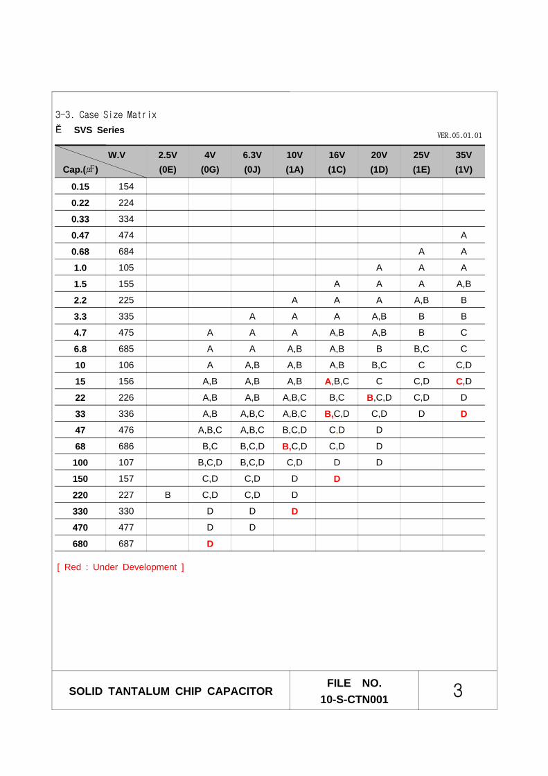
3-3. Case Size Matrix
SVS Series
SOLID TANTALUM CHIP CAPACITORFILE NO.
10-S-CTN001 3
W.VCap.()
2.5V(0E)
4V(0G)
6.3V(0J)
10V(1A)
16V(1C)
20V(1D)
25V(1E)
35V(1V)
0.15 154
0.22 224
0.33 334
0.47 474 A
0.68 684 A A
1.0 105 A A A
1.5 155 A A A A,B
2.2 225 A A A A,B B
3.3 335 A A A A,B B B
4.7 475 A A A A,B A,B B C
6.8 685 A A A,B A,B B B,C C
10 106 A A,B A,B A,B B,C C C,D
15 156 A,B A,B A,B A,B,C C C,D C,D
22 226 A,B A,B A,B,C B,C B,C,D C,D D
33 336 A,B A,B,C A,B,C B,C,D C,D D D
47 476 A,B,C A,B,C B,C,D C,D D
68 686 B,C B,C,D B,C,D C,D D
100 107 B,C,D B,C,D C,D D D
150 157 C,D C,D D D
220 227 B C,D C,D D
330 330 D D D
470 477 D D
680 687 D
[ Red : Under Development ]
VER.05.01.01
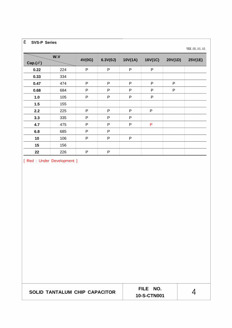
SVS-P Series
SOLID TANTALUM CHIP CAPACITORFILE NO.
10-S-CTN001 4
W.VCap.()
4V(0G) 6.3V(0J) 10V(1A) 16V(1C) 20V(1D) 25V(1E)
0.22 224 P P P P
0.33 334
0.47 474 P P P P P
0.68 684 P P P P P
1.0 105 P P P P
1.5 155
2.2 225 P P P P
3.3 335 P P P
4.7 475 P P P P
6.8 685 P P
10 106 P P P
15 156
22 226 P P
VER.05.01.01
[ Red : Under Development ]
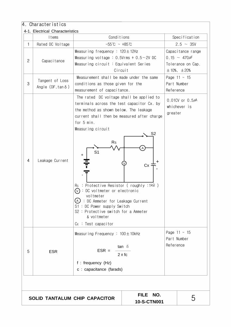
4. Characteristics
4-1. Electrical Characteristics
SOLID TANTALUM CHIP CAPACITORFILE NO.
10-S-CTN001 5
Items Conditions Specification
1 Rated DC Voltage -55 ~ +85 2.5 ∼ 35V
2 Capacitance
Measuring frequency : 120±12Hz
Measuring voltage : 0.5Vrms + 0.5∼2V DC
Measuring circuit : Equivalent Series
Circuit
Capacitance range
0.15 ∼ 470
Tolerance on Cap.
±10%, ±20%
3Tangent of Loss
Angle (DF,tanδ)
Measurement shall be made under the same
conditions as those given for the
measurement of capacitance.
Page 11 ~ 15
Part Number
Reference
4 Leakage Current
The rated DC voltage shall be applied to
terminals across the test capacitor Cx. by
the method as shown below. The leakage
current shall then be measured after charge
for 5 min.
Measuring circuit
RS : Protective Resistor ( roughly :1 )
: DC voltmeter or electronic
voltmeter
: DC Ammeter for Leakage Current
S1 : DC Power supply Switch
S2 : Protective switch for a Ammeter
& voltmeter
CX : Test capacitor
0.01CV or 0.5
whichever is
greater
5 ESR
Measuring Frequency : 100±10kHz
tan δESR =
2πfc
f : frequency (Hz)c : capacitance (farads)
Page 11 ~ 15
Part Number
Reference
V
+
-
A
RS
S1
S2
V Cx+-
A
SOLID TANTALUM CHIP CAPACITORFILE NO.
10-S-CTN001 6
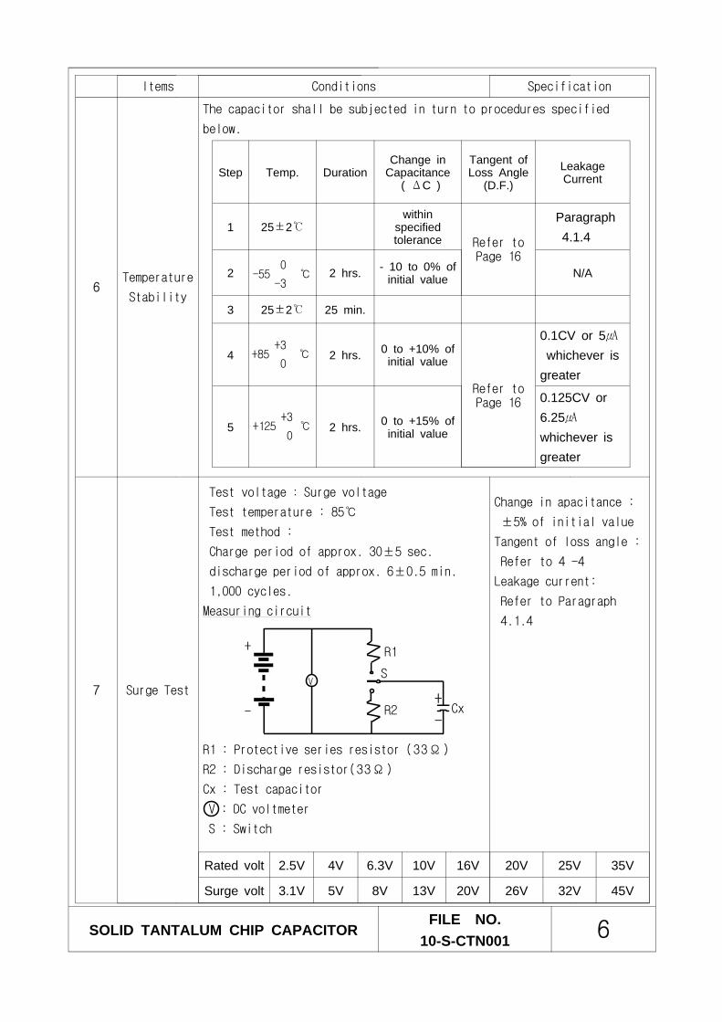
Items Conditions Specification
6Temperature
Stability
The capacitor shall be subjected in turn to procedures specified
below.
7 Surge Test
Test voltage : Surge voltage
Test temperature : 85
Test method :
Charge period of approx. 30±5 sec.
discharge period of approx. 6±0.5 min.
1,000 cycles.
Measuring circuit
R1 : Protective series resistor (33Ω)
R2 : Discharge resistor(33Ω)
Cx : Test capacitor
V : DC voltmeter
S : Switch
Change in apacitance :
±5% of initial value
Tangent of loss angle :
Refer to 4 -4
Leakage current:
Refer to Paragraph
4.1.4
V
+
-
R1
R2
S
Cx+
-
Rated volt 2.5V 4V 6.3V 10V 16V 20V 25V 35V
Surge volt 3.1V 5V 8V 13V 20V 26V 32V 45V
Step Temp. DurationChange in
Capacitance( ΔC )
Tangent ofLoss Angle
(D.F.)LeakageCurrent
1 25±2within
specifiedtolerance Refer to
Page 16
Paragraph4.1.4
2 2 hrs. - 10 to 0% ofinitial value N/A
3 25±2 25 min.
4 2 hrs. 0 to +10% ofinitial value
Refer toPage 16
0.1CV or 5whichever is
greater
5 2 hrs. 0 to +15% ofinitial value
0.125CV or6.25whichever isgreater
+125 +3
0
+85 +3
0
-55 0
-3
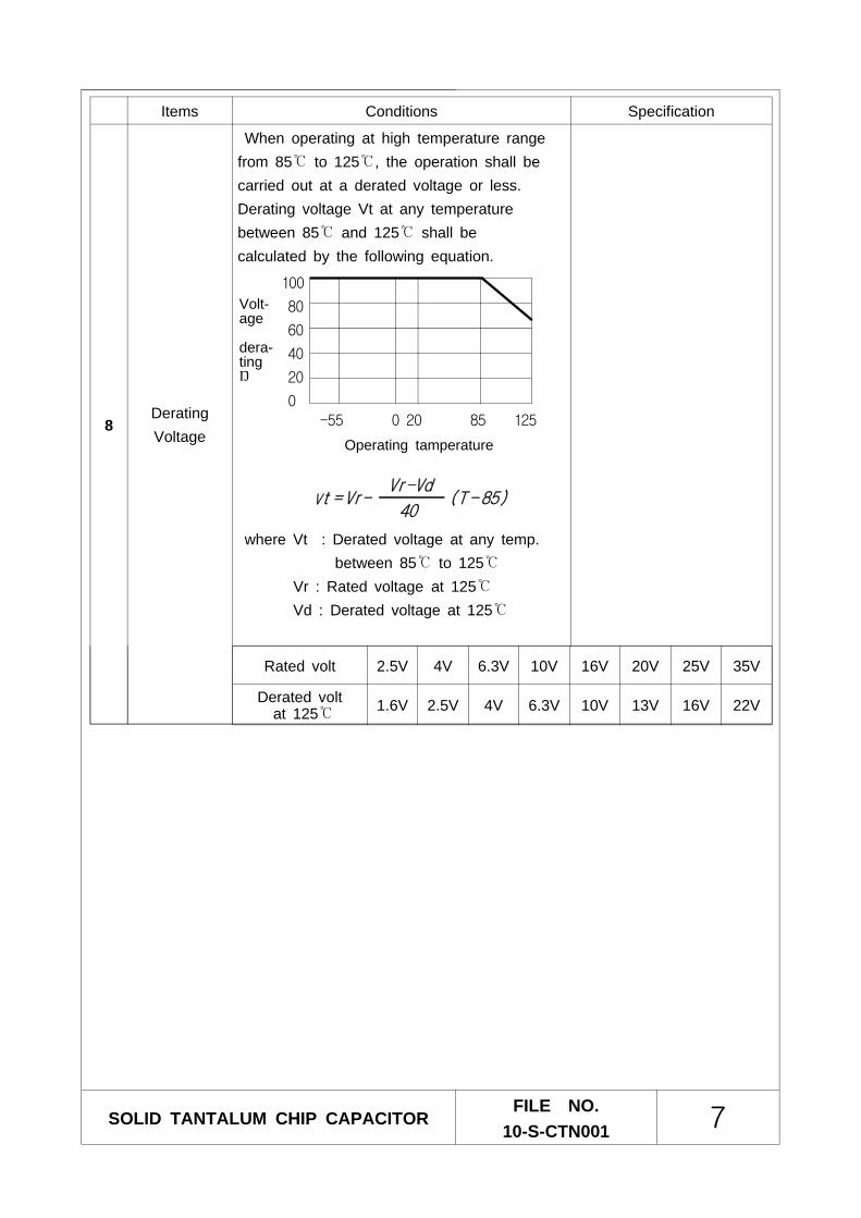
Items Conditions Specification
8DeratingVoltage
When operating at high temperature rangefrom 85 to 125, the operation shall becarried out at a derated voltage or less.Derating voltage Vt at any temperaturebetween 85 and 125 shall becalculated by the following equation.
where Vt : Derated voltage at any temp.between 85 to 125
Vr : Rated voltage at 125Vd : Derated voltage at 125
SOLID TANTALUM CHIP CAPACITORFILE NO.
10-S-CTN001 7
Rated volt 2.5V 4V 6.3V 10V 16V 20V 25V 35V
Derated voltat 125 1.6V 2.5V 4V 6.3V 10V 13V 16V 22V
-55 0 20 85 125
100
80
60
40
20
0
Operating tamperature
Volt-age
dera-ting%
Vt = Vr- (T - 85)Vr-Vd
40
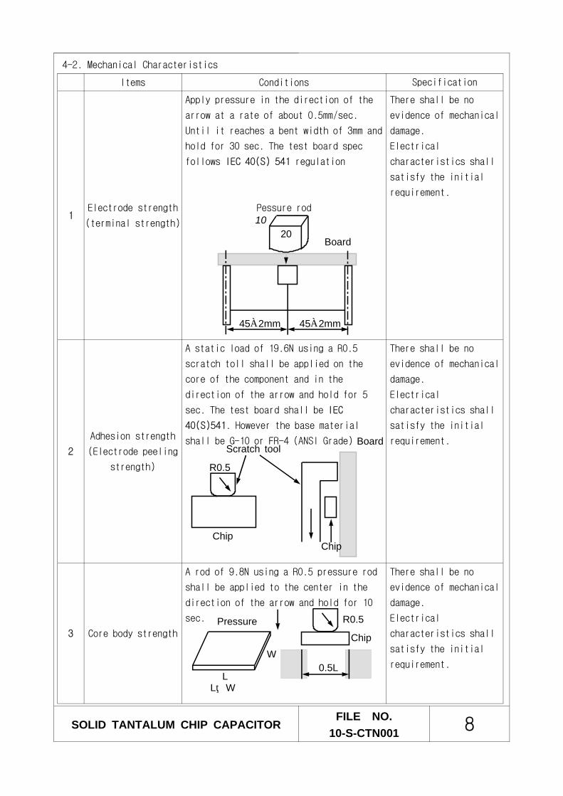
Items Conditions Specification
1Electrode strength
(terminal strength)
Apply pressure in the direction of the
arrow at a rate of about 0.5mm/sec.
Until it reaches a bent width of 3mm and
hold for 30 sec. The test board spec
follows IEC 40(S) 541 regulation
Pessure rod
There shall be no
evidence of mechanical
damage.
Electrical
characteristics shall
satisfy the initial
requirement.
2
Adhesion strength
(Electrode peeling
strength)
A static load of 19.6N using a R0.5
scratch toll shall be applied on the
core of the component and in the
direction of the arrow and hold for 5
sec. The test board shall be IEC
40(S)541. However the base material
shall be G-10 or FR-4 (ANSI Grade)
There shall be no
evidence of mechanical
damage.
Electrical
characteristics shall
satisfy the initial
requirement.
3 Core body strength
A rod of 9.8N using a R0.5 pressure rod
shall be applied to the center in the
direction of the arrow and hold for 10
sec.
There shall be no
evidence of mechanical
damage.
Electrical
characteristics shall
satisfy the initial
requirement.
45±2mm 45±2mm
Board20
Scratch tool
R0.5
Board
ChipChip
R0.5
0.5L
ChipPressure
W
L
4-2. Mechanical Characteristics
SOLID TANTALUM CHIP CAPACITORFILE NO.
10-S-CTN001 8
L>W
10
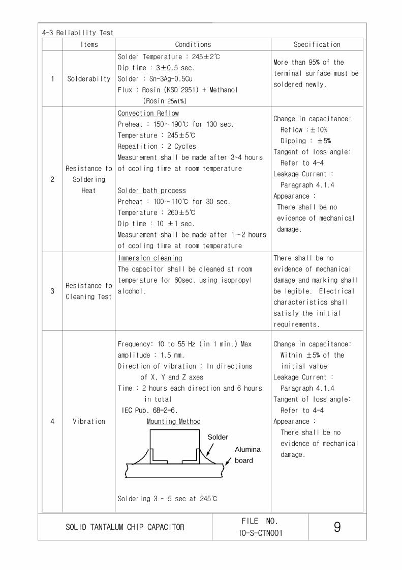
Items Conditions Specification
1 Solderabilty
Solder Temperature : 245±2
Dip time : 3±0.5 sec.
Solder : Sn-3Ag-0.5Cu
Flux : Rosin (KSD 2951) + Methanol
(Rosin 25wt%)
More than 95% of the
terminal surface must be
soldered newly.
2
Resistance to
Soldering
Heat
Convection Reflow
Preheat : 150∼190 for 130 sec.
Temperature : 245±5
Repeatition : 2 Cycles
Measurement shall be made after 3~4 hours
of cooling time at room temperature
Solder bath process
Preheat : 100∼110 for 30 sec.
Temperature : 260±5
Dip time : 10 ±1 sec.
Measurement shall be made after 1∼2 hours
of cooling time at room temperature
Change in capacitance:
Reflow :±10%
Dipping : ±5%
Tangent of loss angle:
Refer to 4-4
Leakage Current :
Paragraph 4.1.4
Appearance :
There shall be no
evidence of mechanical
damage.
3Resistance to
Cleaning Test
Immersion cleaning
The capacitor shall be cleaned at room
temperature for 60sec. using isopropyl
alcohol.
There shall be no
evidence of mechanical
damage and marking shall
be legible. Electrical
characteristics shall
satisfy the initial
requirements.
4 Vibration
Frequency: 10 to 55 Hz (in 1 min.) Max
amplitude : 1.5 mm.
Direction of vibration : In directions
of X, Y and Z axes
Time : 2 hours each direction and 6 hours
in total
IEC Pub. 68-2-6.
Mounting Method
Soldering 3 ~ 5 sec at 245
Change in capacitance:
Within ±5% of the
initial value
Leakage Current :
Paragraph 4.1.4
Tangent of loss angle:
Refer to 4-4
Appearance :
There shall be no
evidence of mechanical
damage.
Solder
Aluminaboard
SOLID TANTALUM CHIP CAPACITORFILE NO.
10-S-CTN001 9
4-3 Reliability Test
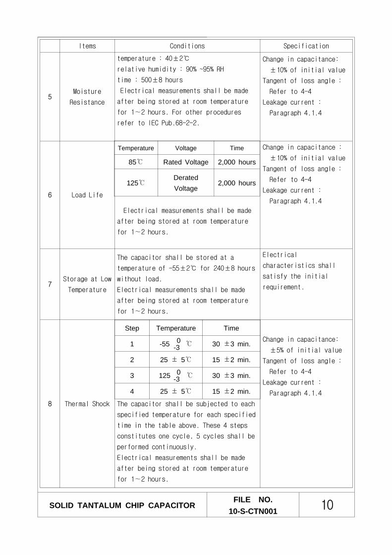
Items Conditions Specification
5Moisture
Resistance
temperature : 40±2
relative humidity : 90% ~95% RH
time : 500±8 hours
Electrical measurements shall be made
after being stored at room temperature
for 1∼2 hours. For other procedures
refer to IEC Pub.68-2-2.
Change in capacitance:
±10% of initial value
Tangent of loss angle :
Refer to 4-4
Leakage current :
Paragraph 4.1.4
6 Load Life
Electrical measurements shall be made
after being stored at room temperature
for 1∼2 hours.
Change in capacitance :
±10% of initial value
Tangent of loss angle :
Refer to 4-4
Leakage current :
Paragraph 4.1.4
7Storage at Low
Temperature
The capacitor shall be stored at a
temperature of -55±2 for 240±8 hours
without load.
Electrical measurements shall be made
after being stored at room temperature
for 1∼2 hours.
Electrical
characteristics shall
satisfy the initial
requirement.
8 Thermal Shock The capacitor shall be subjected to each
specified temperature for each specified
time in the table above. These 4 steps
constitutes one cycle, 5 cycles shall be
performed continuously.
Electrical measurements shall be made
after being stored at room temperature
for 1∼2 hours.
Change in capacitance:
±5% of initial value
Tangent of loss angle :
Refer to 4-4
Leakage current :
Paragraph 4.1.4
Temperature Voltage Time
85 Rated Voltage 2,000 hours
125DeratedVoltage
2,000 hours
Step Temperature Time
1 -55 30 ±3 min.
2 25 ± 5 15 ±2 min.
3 125 30 ±3 min.
4 25 ± 5 15 ±2 min.
0-3
0-3
SOLID TANTALUM CHIP CAPACITORFILE NO.
10-S-CTN001 10

SOLID TANTALUM CHIP CAPACITORFILE NO.
10-S-CTN001 11
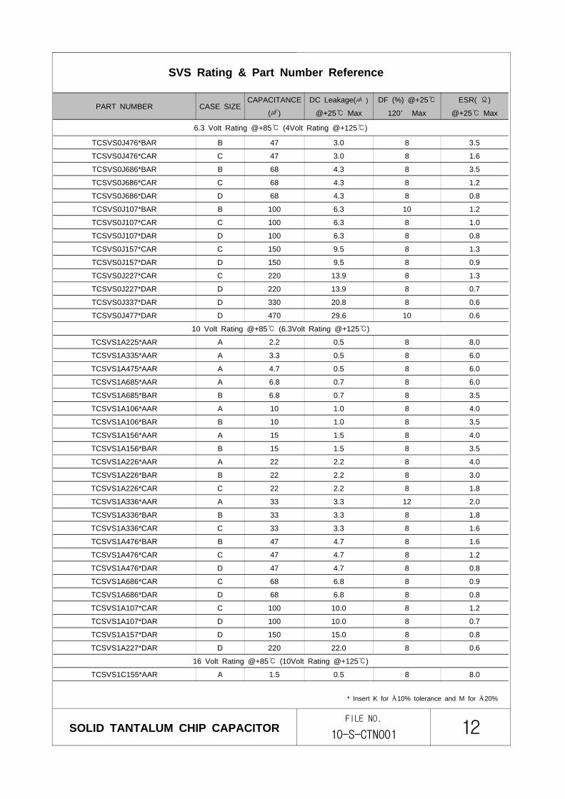
TANTALUM CHIP CAPACITORS (SVS SERIES)SVS Rating & Part Number Reference
PART NUMBER CASE SIZECAPACITANCE
()
DC Leakage( )
@+25 Max
DF (%) @+25
120 Max
ESR( Ω)
@+25 Max
2.5 Volt Rating @+85 (1.6Volt Rating @+125)
TCSVS0E227*BAR B 220 5.5 18 1.2
4 Volt Rating @+85 (2.5Volt Rating @+125)
TCSVS0G475*AAR A 4.7 0.5 8 8.0
TCSVS0G685*AAR A 6.8 0.5 8 6.0
TCSVS0G106*AAR A 10 0.5 8 6.0
TCSVS0G156*AAR A 15 0.6 8 4.0
TCSVS0G156*BAR B 15 0.6 8 3.5
TCSVS0G226*AAR A 22 0.9 8 4.0
TCSVS0G226*BAR B 22 0.9 8 3.5
TCSVS0G336*AAR A 33 1.3 8 4.0
TCSVS0G336*BAR B 33 1.3 8 3.5
TCSVS0G476*AAR A 47 1.9 8 3.5
TCSVS0G476*BAR B 47 1.9 8 3.5
TCSVS0G476*CAR C 47 1.9 8 1.8
TCSVS0G686*BAR B 68 2.7 8 1.8
TCSVS0G686*CAR C 68 2.7 8 1.6
TCSVS0G107*BAR B 100 4.0 8 3.5
TCSVS0G107*CAR C 100 4.0 8 1.6
TCSVS0G107*DAR D 100 4.0 8 0.8
TCSVS0G157*CAR C 150 6.0 8 1.2
TCSVS0G157*DAR D 150 6.0 8 0.8
TCSVS0G227*CAR C 220 8.8 8 1.2
TCSVS0G227*DAR D 220 8.8 8 0.9
TCSVS0G337*DAR D 330 13.2 8 0.8
TCSVS0G477*DAR D 470 18.8 10 0.6
6.3 Volt Rating @+85 (4Volt Rating @+125)
TCSVS0J335*AAR A 3.3 0.5 8 8.0
TCSVS0J475*AAR A 4.7 0.5 8 6.0
TCSVS0J685*AAR A 6.8 0.5 8 6.0
TCSVS0J106*AAR A 10 0.6 8 4.0
TCSVS0J106*BAR B 10 0.6 8 3.5
TCSVS0J156*AAR A 15 1.0 8 4.0
TCSVS0J156*BAR B 15 1.0 8 3.5
TCSVS0J226*AAR A 22 1.4 8 3.5
TCSVS0J226*BAR B 22 1.4 8 3.5
TCSVS0J336*AAR A 33 2.1 6 2.5
TCSVS0J336*BAR B 33 2.1 8 3.0
TCSVS0J336*CAR C 33 2.1 8 1.8
TCSVS0J476*AAR A 47 3.0 12 2.0
* Insert K for ±10% tolerance and M for ±20%
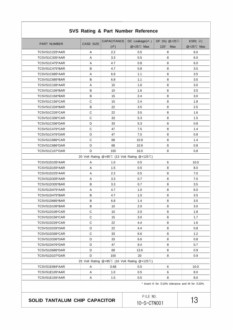
4-4 Part No. List
SOLID TANTALUM CHIP CAPACITORFILE NO.
10-S-CTN001 12
PART NUMBER CASE SIZECAPACITANCE
()
DC Leakage( )
@+25 Max
DF (%) @+25
120 Max
ESR( Ω)
@+25 Max
6.3 Volt Rating @+85 (4Volt Rating @+125)
TCSVS0J476*BAR B 47 3.0 8 3.5
TCSVS0J476*CAR C 47 3.0 8 1.6
TCSVS0J686*BAR B 68 4.3 8 3.5
TCSVS0J686*CAR C 68 4.3 8 1.2
TCSVS0J686*DAR D 68 4.3 8 0.8
TCSVS0J107*BAR B 100 6.3 10 1.2
TCSVS0J107*CAR C 100 6.3 8 1.0
TCSVS0J107*DAR D 100 6.3 8 0.8
TCSVS0J157*CAR C 150 9.5 8 1.3
TCSVS0J157*DAR D 150 9.5 8 0.9
TCSVS0J227*CAR C 220 13.9 8 1.3
TCSVS0J227*DAR D 220 13.9 8 0.7
TCSVS0J337*DAR D 330 20.8 8 0.6
TCSVS0J477*DAR D 470 29.6 10 0.6
10 Volt Rating @+85 (6.3Volt Rating @+125)
TCSVS1A225*AAR A 2.2 0.5 8 8.0
TCSVS1A335*AAR A 3.3 0.5 8 6.0
TCSVS1A475*AAR A 4.7 0.5 8 6.0
TCSVS1A685*AAR A 6.8 0.7 8 6.0
TCSVS1A685*BAR B 6.8 0.7 8 3.5
TCSVS1A106*AAR A 10 1.0 8 4.0
TCSVS1A106*BAR B 10 1.0 8 3.5
TCSVS1A156*AAR A 15 1.5 8 4.0
TCSVS1A156*BAR B 15 1.5 8 3.5
TCSVS1A226*AAR A 22 2.2 8 4.0
TCSVS1A226*BAR B 22 2.2 8 3.0
TCSVS1A226*CAR C 22 2.2 8 1.8
TCSVS1A336*AAR A 33 3.3 12 2.0
TCSVS1A336*BAR B 33 3.3 8 1.8
TCSVS1A336*CAR C 33 3.3 8 1.6
TCSVS1A476*BAR B 47 4.7 8 1.6
TCSVS1A476*CAR C 47 4.7 8 1.2
TCSVS1A476*DAR D 47 4.7 8 0.8
TCSVS1A686*CAR C 68 6.8 8 0.9
TCSVS1A686*DAR D 68 6.8 8 0.8
TCSVS1A107*CAR C 100 10.0 8 1.2
TCSVS1A107*DAR D 100 10.0 8 0.7
TCSVS1A157*DAR D 150 15.0 8 0.8
TCSVS1A227*DAR D 220 22.0 8 0.6
16 Volt Rating @+85 (10Volt Rating @+125)
TCSVS1C155*AAR A 1.5 0.5 8 8.0
* Insert K for ±10% tolerance and M for ±20%
SVS Rating & Part Number Reference
SOLID TANTALUM CHIP CAPACITORFILE NO.
10-S-CTN001 13
PART NUMBER CASE SIZECAPACITANCE
()
DC Leakage( )
@+25 Max
DF (%) @+25
120 Max
ESR( Ω)
@+25 Max
TCSVS1C225*AAR A 2.2 0.5 8 6.0
TCSVS1C335*AAR A 3.3 0.5 8 6.0
TCSVS1C475*AAR A 4.7 0.8 8 6.0
TCSVS1C475*BAR B 4.7 0.8 8 3.5
TCSVS1C685*AAR A 6.8 1.1 8 3.5
TCSVS1C685*BAR B 6.8 1.1 8 3.5
TCSVS1C106*AAR A 10 1.6 8 3.0
TCSVS1C106*BAR B 10 1.6 8 3.5
TCSVS1C156*BAR B 15 2.4 8 3.0
TCSVS1C156*CAR C 15 2.4 8 1.8
TCSVS1C226*BAR B 22 3.5 8 2.5
TCSVS1C226*CAR C 22 3.5 8 1.6
TCSVS1C336*CAR C 33 5.3 8 1.5
TCSVS1C336*DAR D 33 5.3 8 0.8
TCSVS1C476*CAR C 47 7.5 8 1.4
TCSVS1C476*DAR D 47 7.5 8 0.8
TCSVS1C686*CAR C 68 10.9 8 1.4
TCSVS1C686*DAR D 68 10.9 8 0.8
TCSVS1C107*DAR D 100 16.0 8 0.8
20 Volt Rating @+85 (13 Volt Rating @+125)
TCSVS1D105*AAR A 1.0 0.5 6 10.0
TCSVS1D155*AAR A 1.5 0.5 8 8.0
TCSVS1D225*AAR A 2.2 0.5 8 7.0
TCSVS1D335*AAR A 3.3 0.7 8 7.0
TCSVS1D335*BAR B 3.3 0.7 8 3.5
TCSVS1D475*AAR A 4.7 1.0 8 6.0
TCSVS1D475*BAR B 4.7 1.0 8 3.5
TCSVS1D685*BAR B 6.8 1.4 8 3.5
TCSVS1D106*BAR B 10 2.0 8 3.0
TCSVS1D106*CAR C 10 2.0 8 1.8
TCSVS1D156*CAR C 15 3.0 8 1.7
TCSVS1D226*CAR C 22 4.4 8 1.6
TCSVS1D226*DAR D 22 4.4 8 0.8
TCSVS1D336*CAR C 33 6.6 8 1.2
TCSVS1D336*DAR D 33 6.6 8 0.8
TCSVS1D476*DAR D 47 9.4 8 0.7
TCSVS1D686*DAR D 68 13.6 8 0.9
TCSVS1D107*DAR D 100 20 8 0.9
25 Volt Rating @+85 (16 Volt Rating @+125)
TCSVS1E684*AAR A 0.68 0.5 6 10.0
TCSVS1E105*AAR A 1.0 0.5 6 8.0
TCSVS1E155*AAR A 1.5 0.5 8 8.0
* Insert K for ±10% tolerance and M for ±20%
SVS Rating & Part Number Reference
SOLID TANTALUM CHIP CAPACITORFILE NO.
10-S-CTN001 14
PART NUMBER CASE SIZECAPACITANCE
()
DC Leakage( )
@+25 Max
DF (%) @+25
120 Max
ESR( Ω)
@+25 Max
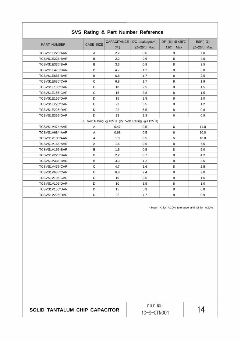
TCSVS1E225*AAR A 2.2 0.6 8 7.0
TCSVS1E225*BAR B 2.2 0.6 8 4.5
TCSVS1E335*BAR B 3.3 0.8 8 3.5
TCSVS1E475*BAR B 4.7 1.2 8 3.0
TCSVS1E685*BAR B 6.8 1.7 8 2.5
TCSVS1E685*CAR C 6.8 1.7 8 1.9
TCSVS1E106*CAR C 10 2.5 8 1.5
TCSVS1E156*CAR C 15 3.8 8 1.5
TCSVS1E156*DAR D 15 3.8 8 1.0
TCSVS1E226*CAR C 22 5.5 8 1.2
TCSVS1E226*DAR D 22 5.5 8 0.8
TCSVS1E336*DAR D 33 8.3 6 0.9
35 Volt Rating @+85 (22 Volt Rating @+125)
TCSVS1V474*AAR A 0.47 0.5 6 14.0
TCSVS1V684*AAR A 0.68 0.5 6 10.0
TCSVS1V105*AAR A 1.0 0.5 6 10.0
TCSVS1V155*AAR A 1.5 0.5 8 7.5
TCSVS1V155*BAR B 1.5 0.5 8 5.0
TCSVS1V225*BAR B 2.2 0.7 8 4.2
TCSVS1V335*BAR B 3.3 1.2 8 3.5
TCSVS1V475*CAR C 4.7 1.6 8 2.5
TCSVS1V685*CAR C 6.8 2.4 8 2.0
TCSVS1V106*CAR C 10 3.5 8 1.6
TCSVS1V106*DAR D 10 3.5 8 1.0
TCSVS1V156*DAR D 15 5.3 8 0.8
TCSVS1V226*DAR D 22 7.7 8 0.9
* Insert K for ±10% tolerance and M for ±20%
SVS Rating & Part Number Reference
SOLID TANTALUM CHIP CAPACITORFILE NO.
10-S-CTN001 15
PART NUMBERCASE
SIZE
CAPACITANCE
()
DC Leakage( )
@+25 Max
DF (%) @+25
120 Max
ESR( Ω)
@+25 Max
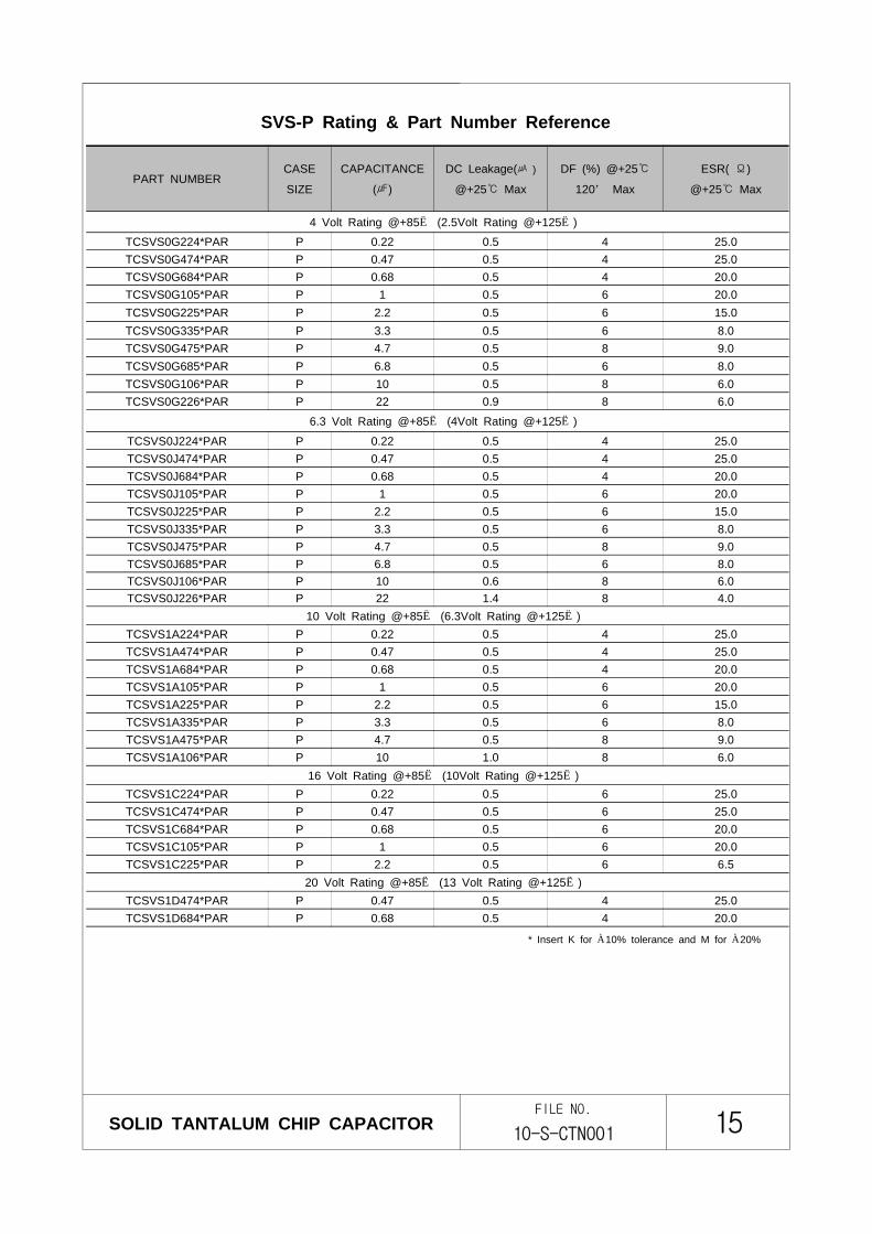
4 Volt Rating @+85 (2.5Volt Rating @+125)
TCSVS0G224*PAR P 0.22 0.5 4 25.0TCSVS0G474*PAR P 0.47 0.5 4 25.0TCSVS0G684*PAR P 0.68 0.5 4 20.0TCSVS0G105*PAR P 1 0.5 6 20.0TCSVS0G225*PAR P 2.2 0.5 6 15.0TCSVS0G335*PAR P 3.3 0.5 6 8.0TCSVS0G475*PAR P 4.7 0.5 8 9.0TCSVS0G685*PAR P 6.8 0.5 6 8.0TCSVS0G106*PAR P 10 0.5 8 6.0TCSVS0G226*PAR P 22 0.9 8 6.0
6.3 Volt Rating @+85 (4Volt Rating @+125)
TCSVS0J224*PAR P 0.22 0.5 4 25.0TCSVS0J474*PAR P 0.47 0.5 4 25.0TCSVS0J684*PAR P 0.68 0.5 4 20.0TCSVS0J105*PAR P 1 0.5 6 20.0TCSVS0J225*PAR P 2.2 0.5 6 15.0TCSVS0J335*PAR P 3.3 0.5 6 8.0TCSVS0J475*PAR P 4.7 0.5 8 9.0TCSVS0J685*PAR P 6.8 0.5 6 8.0TCSVS0J106*PAR P 10 0.6 8 6.0TCSVS0J226*PAR P 22 1.4 8 4.0
10 Volt Rating @+85 (6.3Volt Rating @+125)TCSVS1A224*PAR P 0.22 0.5 4 25.0TCSVS1A474*PAR P 0.47 0.5 4 25.0TCSVS1A684*PAR P 0.68 0.5 4 20.0TCSVS1A105*PAR P 1 0.5 6 20.0TCSVS1A225*PAR P 2.2 0.5 6 15.0TCSVS1A335*PAR P 3.3 0.5 6 8.0TCSVS1A475*PAR P 4.7 0.5 8 9.0TCSVS1A106*PAR P 10 1.0 8 6.0
16 Volt Rating @+85 (10Volt Rating @+125)TCSVS1C224*PAR P 0.22 0.5 6 25.0TCSVS1C474*PAR P 0.47 0.5 6 25.0TCSVS1C684*PAR P 0.68 0.5 6 20.0TCSVS1C105*PAR P 1 0.5 6 20.0TCSVS1C225*PAR P 2.2 0.5 6 6.5
20 Volt Rating @+85 (13 Volt Rating @+125)TCSVS1D474*PAR P 0.47 0.5 4 25.0TCSVS1D684*PAR P 0.68 0.5 4 20.0
SVS-P Rating & Part Number Reference
* Insert K for ±10% tolerance and M for ±20%
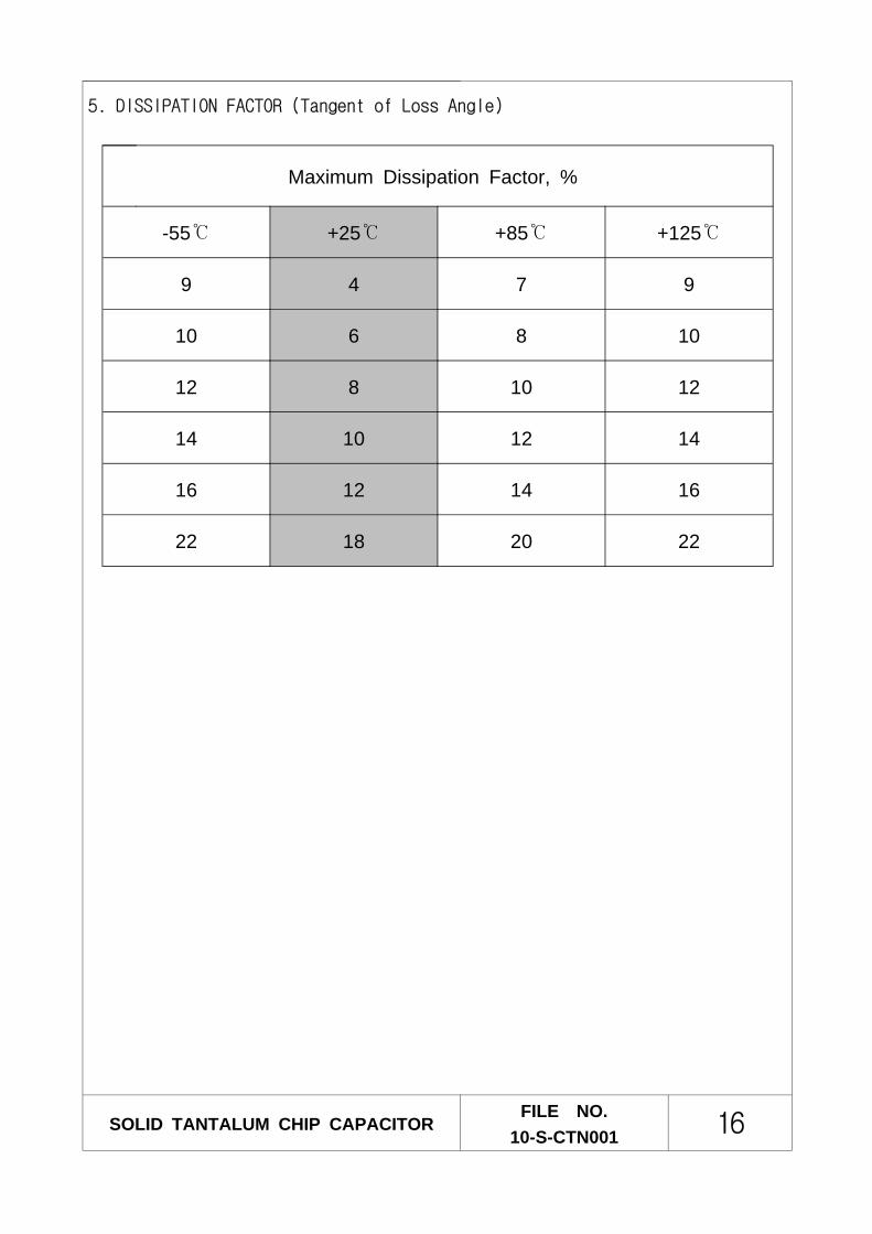
5. DISSIPATION FACTOR (Tangent of Loss Angle)
SOLID TANTALUM CHIP CAPACITORFILE NO.
10-S-CTN001 16
Maximum Dissipation Factor, %
-55 +25 +85 +125
9 4 7 9
10 6 8 10
12 8 10 12
14 10 12 14
16 12 14 16
22 18 20 22
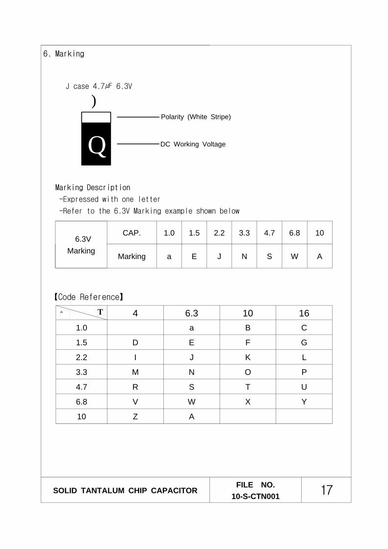
6. Marking
SOLID TANTALUM CHIP CAPACITORFILE NO.
10-S-CTN001 17
J case 4.7 6.3V
4 6.3 10 161.0 a B C
1.5 D E F G
2.2 I J K L
3.3 M N O P
4.7 R S T U
6.8 V W X Y
10 Z A
V
+
S
6.3VMarking
CAP. 1.0 1.5 2.2 3.3 4.7 6.8 10
Marking a E J N S W A
【Code Reference】
Polarity (White Stripe)
DC Working Voltage
Marking Description
-Expressed with one letter
-Refer to the 6.3V Marking example shown below
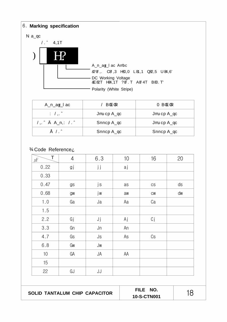
6. Marking specification
SOLID TANTALUM CHIP CAPACITORFILE NO.
10-S-CTN001 18
Capacitance Code
(A:1.0 E:1.5 J:2.2 N:3.3 S:4.7 W:6.8)
DC Working Voltage(G:4V J:6.3V A:10V C:16V D:20V)
P case
10 6.3V
Polarity (White Stripe)
Capacitance 1 DIGIT 2 DIGIT
< 1.0 Lower Case Lower Case
1.0≤ Cap.< 10 Upper Case Lower Case
≥ 10 Upper Case Upper Case
V
JA+
【Code Reference】
4 6.3 10 16 20
0.22 gj jj aj
0.33
0.47 gs js as cs ds
0.68 gw jw aw cw dw
1.0 Ga Ja Aa Ca
1.5
2.2 Gj Jj Aj Cj
3.3 Gn Jn An
4.7 Gs Js As Cs
6.8 Gw Jw
10 GA JA AA
15
22 GJ JJ
SOLID TANTALUM CHIP CAPACITORFILE NO.
10-S-CTN001 19
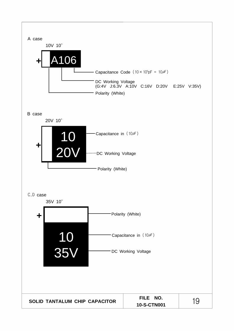
C,D case35V 10
DC Working Voltage
Capacitance in (10)
Polarity (White)
1035V
+
+ A106Capacitance Code (10×106pF = 10)
DC Working Voltage(G:4V J:6.3V A:10V C:16V D:20V E:25V V:35V)
A case10V 10
Polarity (White)
B case20V 10
Polarity (White)
Capacitance in (10)
DC Working Voltage
1020V+

7. Taping Specification
The tantalum chip capacitors shall be packaged in tape and reel form for effective use.
Tape : Semitransparent embossed plasticCover tape : Attached with heating press, polyesterThe tension of removing the cover tape, F=10∼70g
7-1. Carrier Tape Dimension
SOLID TANTALUM CHIP CAPACITORFILE NO.
10-S-CTN001 20
D1
Embossed
D2P0
P1P2
BA
K
t
F
E
W
Right handOrientation available
Embossed Carrier
Removal speed50mm/sec
15˚F
Cover Tape
Unit : mm (inch)
CaseCode
W±0.3(±0.012)
F±0.1(±0.004)
E±0.1(±0.004)
PO±0.1(±0.004)
P1±0.1(±0.004)
P2±0.1(±0.004)
D1+0.1(+0.004)
D2Min. t A±0.2(±0.008)
B±0.2(±0.008)
K±0.2(±0.008)
J
8(0.315)
3.5(0.138)
1.75(0.069)
4(0.157)
2(0.079)
4(0.157)
ø1.5(0.059)
ø0.6(0.024)
0.25(0.0098)
0.98(0.039)
1.80(0.071)
1.0(0.039)
P
ø1.0(0.039)
0.2(0.008)
1.4(0.055)
2.3(0.091)
1.4(0.055)
A 1.9(0.075)
3.5(0.138)
1.9(0.075)
B
0.3(0.012)
3.3(0.130)
3.8(0.150)
2.1(0.083)
C12
(0.472)
5.5(0.217)
8(0.315)
ø1.5(0.059)
3.7(0.146)
6.4(0.252)
3.0(0.118)
4.8(0.189)
7.7(0.303)
3.3(0.130)
D
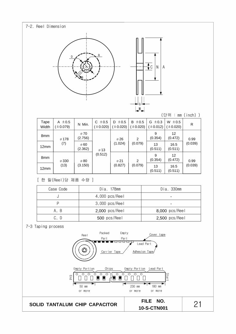
7-2. Reel Dimension
7-3 Taping process
SOLID TANTALUM CHIP CAPACITORFILE NO.
10-S-CTN001 21
TapeWidth
A ±0.5(±0.079) N Min. C ±0.5
(±0.020)D ±0.5(±0.020)
B ±0.5(±0.020)
G ±0.3(±0.012)
W ±0.5(±0.020) R
8mmø178
(7)
ø70(2.756)
ø13(0.512)
ø26(1.024)
2(0.079)
9(0.354)
12(0.472) 0.99
(0.039)12mm ø60
(2.362)13
(0.511)16.5
(0.511)
8mmø330(13)
ø80(3.150)
ø21(0.827)
2(0.079)
9(0.354)
12(0.472) 0.99
(0.039)12mm 13
(0.511)16.5
(0.511)
(단위 : mm (inch) )
[ 한 릴(Reel)당 제품 수량 ]
Case Code Dia. 178mm Dia. 330mm
J 4,000 pcs/Reel -
P 3,000 pcs/Reel -
A, B 2,000 pcs/Reel 8,000 pcs/Reel
C, D 500 pcs/Reel 2,500 pcs/Reel
G
D R
B
C N A
W
ReelPacked
Part
Empty
Part
Lead Part
Adhesion Tape
Start
Empty Portion Chips Empty Portion Lead Part
50 mm
or more
End
230 mm
or more
180 mm
or more
Cover tape
Carrier Tape
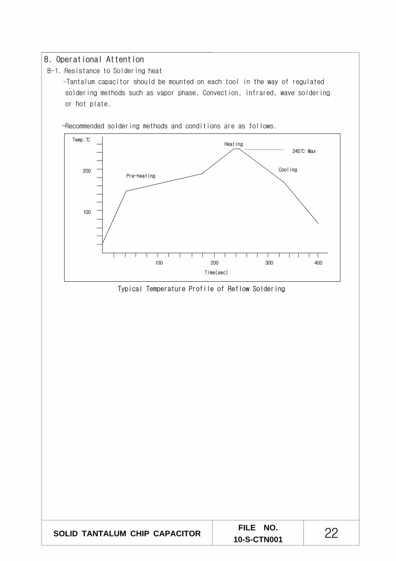
8. Operational Attention
8-1. Resistance to Soldering heat
-Tantalum capacitor should be mounted on each tool in the way of regulated
soldering methods such as vapor phase, Convection, infrared, wave soldering
or hot plate.
-Recommended soldering methods and conditions are as follows.
SOLID TANTALUM CHIP CAPACITORFILE NO.
10-S-CTN001 22
100
200
100 200 300
Time(sec)
Cooling
245 Max
Temp.
Pre-heating
Heating
Typical Temperature Profile of Reflow Soldering
400
8-2. Reverse Voltage
As the solid tantalum chip capacitor has polarity in itself, it should be avoided
applying reciprocal current.
In case of short time current load, the applied voltage should not exceed following
range.
25 C : lower value between 10% of rated voltage and 1.0V
85 C : lower value between 5% of rated voltage and 0.5V
8-3. Ripple Voltage
① The sum of DC voltage and peak ripple voltage should not exceed the rated DC
working voltage of the capacitor. This is based on an ambient temperature of 25.
② For higher temperature, permissible ripple voltage shall be derated as follows.
Permissible voltage at 50 : 0.7 × permissible voltage at 25
Permissible voltage at 85 : 0.5× permissible voltage at 25
Permissible voltage at 125 : 0.3× permissible voltage at 25
8-4. Surge Voltage (Derating Voltage)
① When it is used in power circuit like low impedance circuit, it can possibly
increase the malfunction-rate due to the excessive current.
Therefore it is recommended using capacitor of which rated voltage is three-times
higher than applied voltage to reduce the danger of fire due to the short.
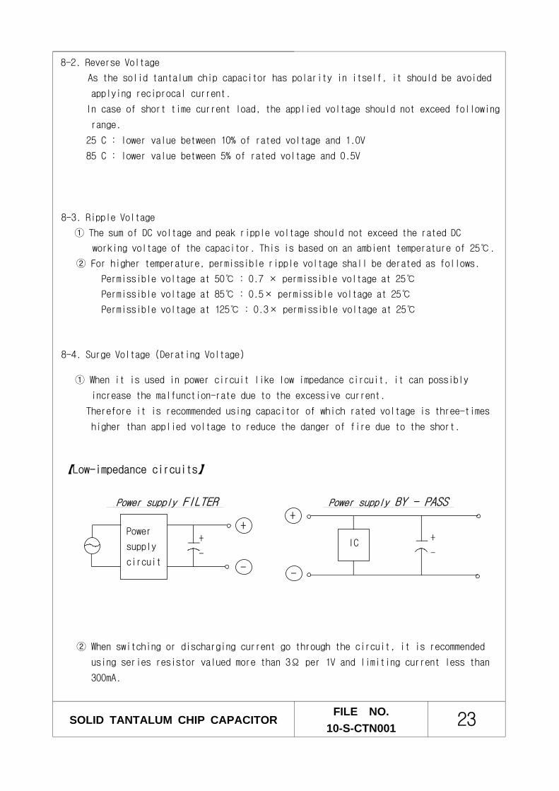
【Low-impedance circuits】
Power supply FILTER Power supply BY - PASS
② When switching or discharging current go through the circuit, it is recommended
using series resistor valued more than 3Ω per 1V and limiting current less than
300mA.
SOLID TANTALUM CHIP CAPACITORFILE NO.
10-S-CTN001 23
IC+
-
+
-
+
-
+
-
Power
supply
circuit
8-5. Mounting
① A capacitor that has been damaged should be discarded to avoid later problems
resulting from mechanical stress.
② Printed circuit boards on which capacitors are mounted should have a low
thermal expansion coefficient.
③ In reflow soldering, if footprints on printed circuit boards are much wider
than the capacitor terminals, the capacitor position may shift when the solder
melts.
④ With reflow or wave soldering, preheating at 150 max. for 5 min. or less is
recommended.
⑤ Pressure limit when mounting.
Pressure should be less than 500g(pressing time should be less than 5 sec) on φ1.5
vessel when pressed in sticking or centering seizer.
Especially, when using chip parts whose height is more than 1mm and the position of
sticking hole is lowered, huge pressure is forced on the capacitor.
Because of this pressing, capacitors and other parts can be flipped out and it will
be the cause of crack.
⑥ Flux
It should be avoided using high activity or acidity materials instead of rosin
metals.
8-6. Washing board
Use Chlorocene, Isopropyl alcohol, Freon-tes, etc. Operation should be done at the
temperature of 50 or less.
And supersonic wave washing should be done less than 5min at 0.02W/.
① During washing like above, it is recommended that you avoid washing mounted
capacitors with other parts.
And you should be careful in supersonic wave washing because the solid part of
other devices impact and cause damage in the lead.
② When you wash in different way, you should be prepared in advance.
8-7 When soldering irons are used for mounting, recommended conditions are as
follows;
1) Iron power : 30 W
2) Iron tip temperature : 300 max.
3) Soldering time : 3 sec. or less
8-8 Storage condition :
Required to store in normal temperature and humidity
(Temp : 5~35, Humidity : less than 75%RH)
SOLID TANTALUM CHIP CAPACITORFILE NO.
10-S-CTN001 24
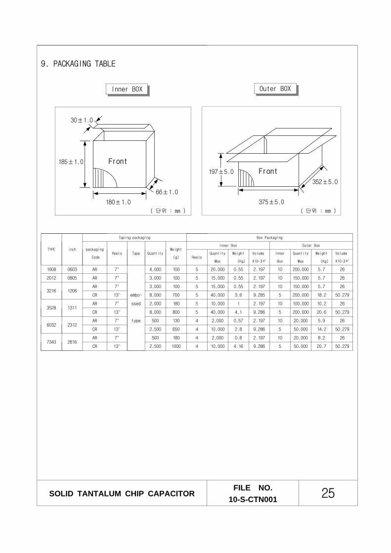
197±5.0 Front
352±5.0
375±5.0
9. PACKAGING TABLE
( 단위 : mm )
30±1.0
185±1.0 Front
66±1.0
180±1.0
( 단위 : mm )
Inner BOX Outer BOX
SOLID TANTALUM CHIP CAPACITORFILE NO.
10-S-CTN001 25
TYPE inch
Taping packaging Box Packaging
packaging
CodeReels Tape Quantity
Weight
(g)
Inner Box Outer Box
ReelsQuantity
Max
Weight
(Kg)
Volume
X10-3
Inner
Box
Quantity
Max
Weight
(Kg)
Volume
X10-3
1608 0603 AR 7"
embo-
ssed
type
4,000 100 5 20,000 0.55 2.197 10 200,000 5.7 26
2012 0805 AR 7" 3,000 100 5 15,000 0.55 2.197 10 150,000 5.7 26
3216 1206AR 7" 3,000 100 5 15,000 0.55 2.197 10 150,000 5.7 26
CR 13" 8,000 700 5 40,000 3.6 9.285 5 200,000 18.2 50.279
3528 1311AR 7" 2,000 180 5 10,000 1 2.197 10 100,000 10.2 26
CR 13" 8,000 800 5 40,000 4.1 9.286 5 200,000 20.6 50.279
6032 2312AR 7" 500 130 4 2,000 0.57 2.197 10 20,000 5.9 26
CR 13" 2,500 650 4 10,000 2.8 9.286 5 50,000 14.2 50.279
7343 2816AR 7" 500 180 4 2,000 0.8 2.197 10 20,000 8.2 26
CR 13" 2,500 1000 4 10,000 4.16 9.286 5 50,000 20.7 50.279
10.PRODUCT FACTORY
Samsung Electro-Mechanics Philippines, Corp.
Block 5, CPIP, Brgy. Batino
Calamba, Laguna
Philippines
11.ENVIRONMENT CONSERVATION
We, Samsung, declare that our component Tantalum capacitor is produced in accordance
with EU RoHS directive.
1. RoHS Compliance and restriction of Br
The following restricted materials are not used in packaging materials as well
as products in compliance with the law and restrintion
- Cd, Pb, Hg, Cr+6, As, Br and the compounds, PCB, asbestos
- Bromic materials : PBBs, PSSOs, PBDO, PBDE, PBB
2. No use of materials breaking Ozone layer
The following ODS materials are not used in our fabrication process.
- ODS material : Freon, Haron, 1-1-1 TCE, CCI4, HCFC
SOLID TANTALUM CHIP CAPACITORFILE NO.
10-S-CTN001 26
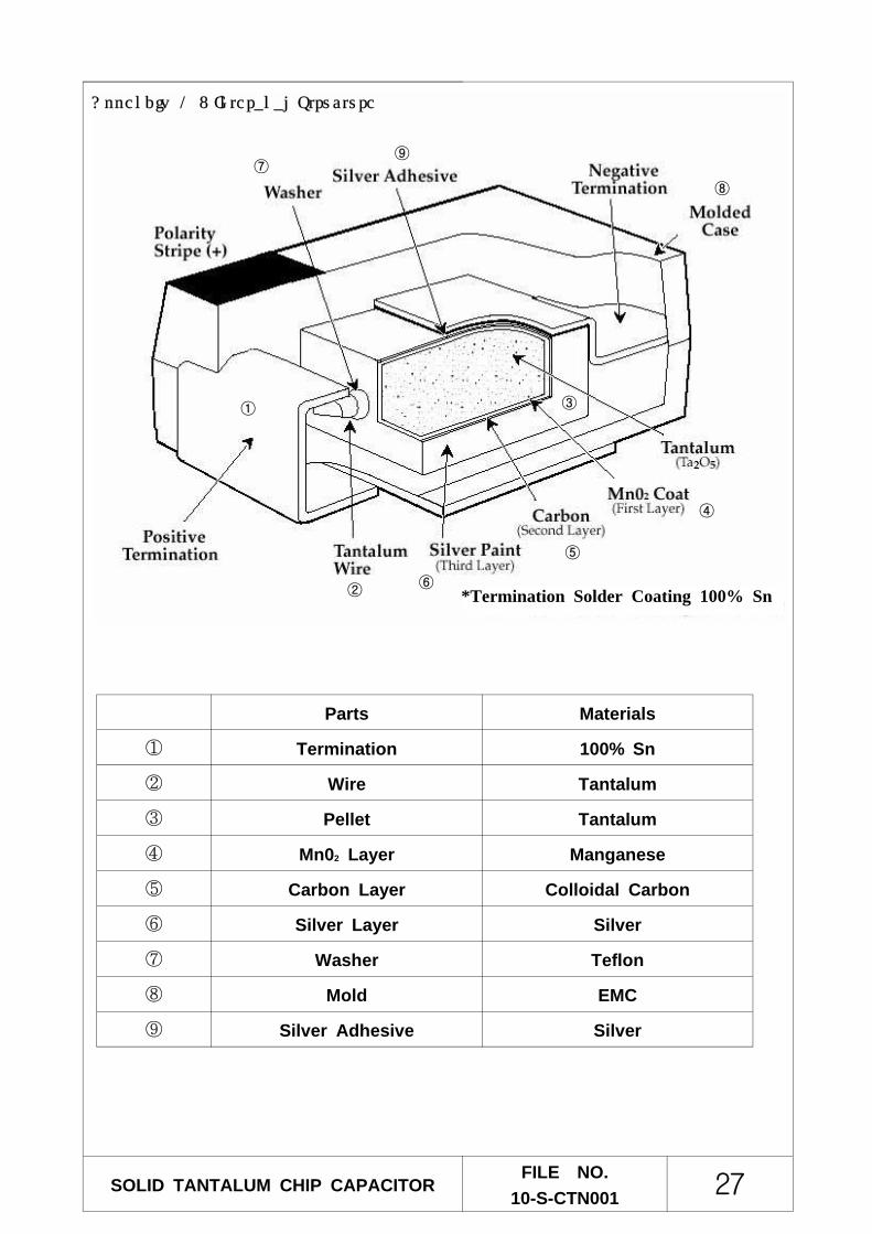
①
②
③
④
⑤
⑥
⑦
⑧
⑨
Parts Materials
① Termination 100% Sn
② Wire Tantalum
③ Pellet Tantalum
④ Mn02 Layer Manganese
⑤ Carbon Layer Colloidal Carbon
⑥ Silver Layer Silver
⑦ Washer Teflon
⑧ Mold EMC
⑨ Silver Adhesive Silver
SOLID TANTALUM CHIP CAPACITORFILE NO.
10-S-CTN001 27
*Termination Solder Coating 100% Sn
Appendix 1 : Interanal Structure


![Svs Agencies[1]](https://img.pdfslide.us/doc/110x75/577cc7a71a28aba711a191e1/svs-agencies1.jpg)