Embed Size (px)
Citation preview
$
Te 5-31 'DE PART Mt NT 0F THE ARM Y TRAININGel RCULA R
VIET CONG
BOOBYTRAPS, MINES
.AND MINE WARFARE
TECHNIQUES
•~HEADQUARTERS, DEPARTMENT OF THE ARMY MAY 1967
TAGO 5OZ3A
- =
TC 5-31
HEADQUARTERSTRAINING CIBCULAR } DEPARTMENT OF THE ARMY
No. 6-31 WASHINGTON, D.C., 10 May 1967
VIET CONG BOOBYTRAPS, MINES, AND MINE
WARFARE TECHNIQUES
8IlcTION I. INTRODUCTION Purpooe and IOOpe 1 II Conunenta II II
Introductory remarks 8 II
II. MINES AND DEMOLITIONS Antitank mine. 4 8 Antiperoonnel mine. 5 7 Demolition charge. 6 12 Water mine. 7 17
III. FUZES AND FIRING DEVICES Fuze. 8 18
Firing devi... 9 22
IV. BOOBYTRAPS General 10 27
Hand grenade. 11 27
Explo.ive boobytrap. 12 84
Nonexploolve boobytrap. 18 43
V. MINE WARFARE TECHNIQUES General 14 54
Employment of antitank and antlvehlcular mine. 15 54 Employment of antiperoonnel mlneo 16 55 Boobytrap techniquea 17 56
Marking of mine. and boobytrap. by the Viet Cong 18 58
VI. DEFENSE AGAINST VIET CONG MINES AND BOOBYTRAPS
General 19 63
General precautionary measures 20 63 Detection and oeareb technique. 21 64 D10arming method. 22 66 Clearing nonexplo.lve trap. 28 68Reporting 24
68
AGO liOO3A 1
TC 5-31 -SECTION I
INTRODUCTION
1. Purpose and Scope. a. This training circular is a guide for commanders and staffs in the orientation and training of personnel for operations in the Republic of Vietnam. It encompasses Viet Cong mine and boobytrap materiel, techniques of employment, and defensive measures to be taken against Viet Cong mine and boobytrap activities.
b. The material contained herein is applicable without modification to nuclear and nonnuclear warfare.
2. Comments. Users of this training circular are urged to submit recommended changes and comments to improve the circular. Comments should be keyed to the specific page, paragraph, and line of text in which the change is recommended. Reasons should be provided for each comment to insure understanding and complete evaluation. Comments should be forwarded direct to the Commandant, U. S. Army Engineer School, Fort Belvoir, Virginia, 22060
3. Introductory Remarks. a. Viet Cong mines and boobytraps have caused a large number of casualties among U. S. forces in Vietnam. Much has been learned about Viet Cong materiel, equipment, and techniques; however, continuous effort must be made in training programs to thoroughly indoctrinate all personnel in defensive measures against mines and boobytraps in Vietnam.
b. Viet Cong forces have developed a high degree of expertise in the use of mines and boobytraps in their own familiar environment. Employment techniques include the use of mines and boobytraps in defensive and offensive tactics; security of camp sites, villages, and other installations; ambush tactics; harassment, and terrorist activities. All available materiel, manufactured or locally produced, friendly or enemy, is used to their best advantage. The Viet Cong know how to use mines and they use them effectively.
c. Detailed discussion of materiel and equipment in this circular is confined to that of for
eign origin: Viet Cong, North Vietnamese, Soviet, and Communist Chinese. It must be emphasized, however, that Viet Cong forces make extensive use of captured U. S. materiel and equipment, and where appropriate, this is so noted in the text. Detailed discussion of U. S. mines, fuzes, and related materiel is adequately covered in other Department of the Army publications (FM 5--31, FM 20-82, TM 9-1345200).
d. The objective of this training circular is to provide adequate orientation and recognition data on mines and demolitions, fuzes and firing devices, boobytraps, and employment techniques of Viet Cong forces. A section is devoted to recommended defensive measures against VC mines and boobytraps. Although this circular may not include all possible materiel and devices used by the Viet Cong, there are sufficient data to establish a reasonable pattern of operation. Innovations of known techniques may vary widely, but they will not differ greatly from the general pattern.
e. Viet Cong equipment and materiel are discussed in the circular under the definitive titles of antitank mines, antipersonnel mines, demolition charges, water mines, fuzes and firing devices, and boobytraps. As a practical matter, VC materiel and employment techniques do not follow such closely defined titles. For example, mines may be used in either antitank, antivehicular, or antipersonnel roles; demolition charges and artillery shells are. used in a variety of ways; and the distinction between anti: personnel mines and boobytraps is often indistinguishable. The names applied to individual mines and boobytraps in this circular are those most commonly used; however, some units or agencies may refer to them under slightly different names. Users of this circular should learn what materiel and devices are being used by the VC and how they are used and not attempt to place equipment and materiel into academic and inflexible categories.
AGO 502aA 2
TC 5-31
1 1 i
I i ~.
SECTION n
MINES AND DEMOLmONS
4. Antitank Mines. Viet Cong antitank or antivehicular mines vary considerably, and any encased explosive charge of adequate size may be employed. Explosive charges for this purpose range from crude, locally produced items to artillery shells and captured U. S. mines, as well as to'Soviet and Chinese Communist mines. Included in this section are mines either known to have been used or readily available to the Viet COngo
a. BettU Bo:e Mine. The Betal box mine is constructed of concrete and explosive. Ita one fuze well is located on the top at the center of the mine. Used in either an antivehicular or an antipersonnel role, the mine is usually exploded by an electric detonator; other fuzes also may be used.
CHARACTERISTICST7Pe • Antipel8Onnel/antivehicular ~or Gray
Maximum diameter 8 in. Height 7 in. Total weight 18 lb Filler TNT
F/gv.~. 1. Betel b.", "'.....
3
TC 5-31
b. Turtle Mine. The turtle mine, constructed of concrete with explosive inside, is used pri marily as a demolition charge but is often used as a mine. It can be detonated by either an electrical or mechanical fuze (with or without delay). The mine illustrated in figure 2 utilizes a mechanical fuze. When used as a demolition charge, this mine is normally coupled to a pole.
CHARACTERISTICS
Type Dual purpose Color Gray
Maximum diameter 5 in. (end view is semicircular)
Length 9 in.
Overall weight 13 lb Filler TNT
Figure I. Turtle mine.
c. Dud Shell Mine. The dud shell mine is improvised from a dud artillery or mortar projectile. The mine is made by removing the fuze from a projectile and drilling a hole into the explosive for an electric detonator. Batteries or a hand-held generator supply the current to activate the detonator remotely. The mine is usually found along roads or trails. Its effectiveness against armored vehicles and personnel varies with the type and size of projectile used.
CHARACTERISTICS
Type Anl;iperl:>onnellantivehicular Color Varies
Maximum diameter Varies Length Varies
Total weight Varies Filler Usually TNT
Figure 3. Dud .hell mine.
AGO 602aA 4
d. Soviet Model TMB-2 Antitank Mine. The Soviet model TMB-2 antitank mine is constructed from two cardboard pots joined with black tape and coated with asphalt and having a glass stopper on top. Pressure on the mine activates an MV-5 fuze under the glass stopper and explodes the mine. The TMB-2 antitank mine is brownish in color and cannot be detected by a mine detector.
CHARACTERISTICS Type Blast Maximum diameter ~ 10.8 in. Height 5.3 in. Weight 15.4 Ib Actuating force 26 Ib Case material Cardboard Case thickness 0.38 in. Number of fuze wells 1 main Main charge Amatol or TNT Filler weight 11 to 14.5 Ib Fuze model MV-5 Fuze type Pressure Safety device None
TC 5-31
e. Soviet Model TM-J.l Antitank Mine. The Soviet model TM-41 antitank mine is a cylindrical blast-type mine with an MV-5 pressure fuze inside a sheet steel case. It is easily detected with electronic mine detectors. Corrugations on the upper part of the case's side wall control the way in which the case crushes when a vehicle or tank runs over it and also insure reliable functioning of the pressure fuze.
CHARACTERISTICS Type Blast Maximum diameter 10 in. Heigbt 5.8 in. Weight 11.9 Ib Actuating force 440 lb Case material Sheet steel Case weight 3.3 Ib Number of fuze wells 1 main Main charge TNT or amatol Filler weight 8.4 Ib Fuze model MV-5 Fuze type _ Pressure
\ l
Figure 4. Soviet model TMB-2 antitank mine. Figure 5. Soviet model 1'M-~l antitank mine.
AGO 5023A 5
TC 5-31
f. Soviet Model TMN-J,6 Antitank Mine. The model TMN-46 is the latest known Soviet antitank mine. The TMN-46 (fig 6) has a secondary fuze well located in t)J.e bottom of the case. This mine may be emplaced either by hand or by mechanical means. A pressure of about 400 pounds applied to the pressure plate compresses the striker spring in the fuze until the strikerretaining ball escapes into a recess in the pressure cap, thus releasing the spring-loaded striker.
CHARACTERISTICS Type Blast Maximum diameter . 12.2 in. Height 2.9 in. Weight 19.21b Actuating force . Approx 400 Ib Case material Sheet steel Case weight 6.6 Ib Number of fuze wells 2 Main charge TNT Filler weight 12.6 Ib Fuze model MV-5 or MV-5K Fuze type ._. Pressure Safety device None
Figure 6. Soviet model TMN-46 antitank mine.
g. Chinese Communist Antitank Mine. The Chinese Communist antitank mine is copied from the U. S. Ml-series antitank mines. This mine, with a case of very thin sheet steel, has provisions for attaching the pressure plate or spider. The pressure plate, or spider, is a sheet metal disk with four 1.75-inch diameter holes located 90 0 apart in the plate surface. Four lugs welded to the outer edge of the pressure
plate 90 0 apart prevent the plate from misalining with the body when the mine is being emplaced. These lugs also act as guides for the downward movement of the pressure plate when a load is applied. All joints are lapwelded, and the inside of the mine case is sprayed with an asphalt-type paint. This flat cylindrical mine, painted olive drab, has no other markings or identifying features. There are indications that this mine is being locally produced by the Viet Congo
CHARACTERISTICS Type Blast Maximum diameter 7.88 in. Height 2.88 in. Weight 11 lb with pressure plate
and fuze Case material Sheet steel Case thickness 0.08 in. Case weight . 5.75 lb Number of fuze wells 1 main Main charge TNT Filler weight 3.5 Ib Fuze type Pressure Safety device Fork
-
Figure 7. Chinese Communist antitank mine.
AGO S02SA 6
TC 5-31
h. Chinese Communist No . .. Dual-PurpoSE Mine. The Chinese Communist No. 4 dualpurpose mine was designed for use against both personnel and light vehicles. It incorporates a double-acting fuze which will initiate the explosive charge under either of two circumstances: when a load of 300 to 500 pounds is applied to the pressure spider; or when a pull of 10 to 50 pounds is exerted on a tripwire fastened to the fuze's striker-retainer pin. The mine is rustproofed with a compound similar to creosote, and the joint between the two halves of the case is caulked. No.4 mines are packed in individual metal carrying cases.
CHARACTERISTICS Type ~ Blast Maximum diameter 9 in. Height _~ 4 in. Weight Approx 11.4 lb Actuating force 300 to 500 Ib pressure!lO
to 50 lb pull Case material Cast iron Case thickness 0.1 in. Case weight 5.6 Ib Number of fuze wells 1 main Main charge Flake TNT Filler weight Approx 4 lb Fuze type Pressure or pull
Figure 8. Chinese Communist No. 4. dual-purpose mine.
5. Antipersonnel Mines. The number and type of Viet Cong antipersonnel mines vary as much or more than the antitank mines. A significant feature of the antipersonnel mines is that nearly all of them are improvised. Artil lery and mortar shells, hand grenades, and a
't' AGO 5023A
variety of explosive charges are adapted to use as antipersonnel mines. The antipersonnel mines described in this section are typical of Viet Cong innovation and improvisation. When the use of antitank mines and other demolition charges as antipersonnel mines is considered, it becomes evident that Viet Cong employment techniques are almost unlimited.
a. Tin Can Antipersonnel Mine. The tin can mine is constructed from a sheet metal container similar in appearance tO,a beer can. The firing device for the explosive is an improvised fuze with zero delay action. A hand grenade fuze may be used with this munition by removal of the delay element. The mine functions by a tripwire attached to the pull ring device, which when removed allows the spring-driven striker to move downward, hitting the primer and detonating the mine. This mine should never be neutralized by hand because of the possibility of a hang fire.
CHARACTERISTICS Type ---- Antipersonnel Color ------- Gray or green Maximum diameter _~ 3 in. Height - ~~ ~ ~ 6 in. Total weight Approx 2 Ib Filler ----- TNT Fuze delay __ ~_~ ~ ~ None
Figure 9. Tin can antiper80nnel mine.
7
TC 5-31
b. Concrete Fragmentation Mine. The concrete fragmentation mine is constructed of explosive encased in ·cylindrically-shaped concrete with a flat side cor stable emplacement. A 2inch diameter pipe on one end of the mine head serves as a carrying handle and detonator housing. The two swivels on top of the mine are used to tie it to an object. The mine's electrical detonator usually is activated remotely by means of a battery pack or hand-held generator.
CHARACTERISTICS Type Color Length of mine body Width of base Height Total weight Filler Fuze delay
Antipersonnel Gray 10 in. 7 in. 6 in. 13 lb TNT None
CARRYING HANDLE AND DETONATOR HOUSING
ELECTRIC DETONATOR
END VIEW
Figure 10. Concrete fragmentation mine.
c. Concrete Mound Mine. The concrete mound mine is constructed of explosive encased in concrete, but possibly a similar mine of cast iron may be encountered. The mound-shaped mine is electrically fuzed and has two fuze wells, one at each end. The iron pipe at one end of the mine serves as a pole socket, as well as being a housing for one of the fuze wells. Electric current to activate the detonator is provided by a battery pack or hand-held generator.
CHARACTERISTICS Type " Antipersonnel Color Gray Maximum diameter 5.5 in. Length 14 in.
Total weigbt 13 Ib -Filler weight ._ TNT Fuze delay None
ILlCtllC OUONAtOI ___--="-----O.:!>\.._ UIIDI
IU(fIIC DltONU::.:-'----------../
UADI
Figure 11. Concrete mound mine.
d. Cast Iron Fragmentation Antitank Mine. Sometimes referred to as a pineapple fragmentation mine, this is a unique egg-shaped mine constructed of cast iron and is further identified by surface serrations and a carrying handle. The mine has a single fuze well located in one end of the body. It is fuzed with an electric detonator which is activated by current from batteries or a hand-held generator. -
CHARACTERISTICS Type Antipersonnel Color Gray Maximum diameter 5 in. Length 9 in. Total weight 12 lb Filler Melinite/TNT
(AllYING HANDU
CAST liON lOOT
Figure 12. Cast irem fragmentation antitank mine. -AGO 5028A 8
e. Cast Iron Fragmentation Mine, AP. This antipersonnel mine, made of cast iron, resembles a stick hand grenade with a very short handle. The word Min is often found cast into the body. The handle houses a pull-friction, delay-type fuze. A tug on a tripwire attached to the pull wire of the friction fuze will, by extracting the pull wire, ignite the delay element.
CHARACTERISTICS Type .. .__ _ Antipersonnel Color Gray to black Maximum diameter 2 in. Length 6.5 in. Total weight . 2.2 lb Filler :I'NT Fuze delay .._. __ . __ .. . 2 to 4 see
PULL WIRE INSIOE HERE
I ... Figure 13. Cast iron fragmentation mine, AP.
f. B 0 un din g Fragmentation Mine. The bounding fragmentation mine is improvised from U. S. M2 bounding-mine or M48 trip-flare mine cases. A wooden cylinder, slightly smaller in diameter than the mine case, is hollowed out so that a standard grenade (frequently the U. S. M26) can fit inside. The wooden cylinder, with inclosed grenade, is then fitted into the mine case and the grenade's safety pin is ex-
TC 5-31
tracted. When the mine is initiated electrically, either by a battery pack or a hand generator, the cylinder and grenade are propelled upward. As the wooden cylinder with grenade leaves the case, the handle flies off and initiates the fuze train of the grenade.
CHARACTERISTICS Type Antipersonnel Color Olive-drab or gray Maximum diameter 2.5 in. Height 8 in. Total weight .. . 5 lb Filler . __ . Grenade (TNT) Fuze delay __ . . 3 to 4 see (grenade)
HAND GRENADE
LEADS TO .J~~~~r WOCO CYLINDER ELE.CTRIC
DETONATOR
Figure 14. Bounding fragmentation mine.
AGO 5023A 9
- -
TC 5-31
g. Directional Fragmentation Mine (DH10). This directional mine is primarily an antipersonnel mine which also can be used against thin-skinned vehicles or similar items. The concave front or fragmentation face of the mine contains approximately 450 half-inch steel fragments embedded in a matrix, and is backed up by cast TNT. Designed for electrical detonation, the mine is provided with an adjustable frame so that it can be placed on various types of surfaces and aimed in any direction. The single fuze well is centered on the convex (back) of the mine. This mine is often referred to as a VC claymore mine.
CHARACTERISTICS Type Color Maximum diameter Width
Dual purpose Gray to black 18 in. 4 in.
Total weight Filler
20 lb Cast TNT
FRAGMENTATION FACE REAR FACE OF MINE
OETO"ATOR WELL
FiOUKe 15. Direetional fragmentation mine (DB-I0).
-h. Coconut Type Mine. This mine is made from a hollowed out coconut filled with black powder. Using a friction type fuze, this mine is employed in much the same manner as hand grenades when used as antipersonnel mines. It is usually buried approximately six inches un· derground, and it has been covered by rock or brick for missile effect. These mines have been used effectively near gates.
CHARACTERISTICS Type Color . Size Weight
Filler Fuze
ROCKS TRFWR \
FLLER (BLACK POWDER)
Figur6 16. Coconut type mine.
Antipersonnel Brown Varies Varies
Black powder Pul1~friction
-AGO 5028A 10
i. Holww Bamboo Mine. This mine is made from a large piece of bamboo. It is hollowed out and filled with plastic explosive or black powder, together with nuts and bolts, rocks, and scrap metal, or other available material for missile effect. A pull-friction fuze is normally used. This mine may be command detonated with an electrical firing system. It has been used as an improvised demolition charge.
CHARACTERISTICS Type Antipersonnel Color ~~~~~~ Light tan Diameter 2 to 6 in. Length ~_~~__ ~ Approx 2.5 it Weight Varies Filler Black powder/plastic explosive Fuze Pull-friction
PULL OR ELECTRICAL WIRE
BLACK POWDER OR PLASTIC E)(PL.OSIVE "eLER
ROCKS, NALS, NUTS, BOLTS ADDEO FOR FRAGMENTATION
PlI..L-FR1CTION OR ELECTRIC FUZE
ENOS CLOSED
Figure 17. Hollow bamboo mine.
j. VC "Toe Popper" Mine. This mine is fabricated of cartridge cases or pieces of pipe of various sizes. It is loaded with a charge of black powder, a primer, and a variety of fragments for missile effect. When the intended victim steps on the mine, the igniter explodes the black powder charge and propels the fragments upward.
CHARACTERISTICS Type Antipersonnel Color Varies Size . Varies Weight Varies Filler Black powder Fuze Homemade primer
TC 5-31
BLACK POWDER FI.L£R IMPROYlSED
~$n~
PiPE OR CARTRIDGE C"'SE
Figure 18. VC "toe popper" mine.
k. Mud Ball Mine. The mud ball mine consists of a hand grenade encased in sun-baked mud or clay. The safety pin (pull ring) is removed, and mud is molded around the grenade. After the mud dries, it holds the lever of the grenade in the safe position. The mud ball is placed on trails or anywhere troops may walk. Stepping on the ball breaks the dried mud apart and releases the lever, detonating thl! grenade. The U. S. M26 hand grenade has been the most commonly used grenade for this purpose, although other lever type grenades may be used.
CHARACTERISTICS
Type ~ ~~_ Antipersonnel
Color Varies with color of mud
Size ~~ __ ~~ Approx 6-in. diameter
Weight ~ Varies with type grenade and mud Filler ~~ TNT (grenade) Fuze __ ~ Grenade fuze
Figure 19. Mud baU mine.
t AGO 'O'SA 11
- -
TC 5-31
I. Shell Case Mine. The shell case mine has a standard artillery shell casing, mostly 75-, 105-, and 155-mm calibers. A variety of fuzing mechanisms can be improvised for this mine; the mine illustrated in figure 20 is detonated by the potato-masher grenade inserted into the explosive charge. Inserted into the side of the casing are two fuze wells through which electrically or mechanically initiated fuzes may be placed. The mine, generally used in an antipersonnel role, is initiated by a pull on a tripwire strung across a path. In an antivehicular role, the mine is usually command-fired electrically.
CHARACTERISTICS
Type Antipersonnel/antivehicular Color Brass
Maximum diameter 6 in.
Length ~~~~~~~~~~~~~~~~ 18 to 24 in. Total weight ~~~~~~~~~~~ 10 to 15 Ib
Filler ~~~~~~~~~~~~~~~~~~ TNT Fuze delay 3 to 4 sec (with grenade)
POTATO MASHER HAND GRENADE
SHELL CASE
Figure 20. Shell case mine.
-6. Demolition Charges. The Viet Cong forces employ numerous demolition charges as antipersonnel mines and antivehicular mines and boobytraps. As with mines, most demolition charges are locallY fabricated and make use of a variety of explosives. The type of fuze employed will vary with the initiating action desired and availability of fuzes and/or firing devices.
a. Small Shaped Charge Mine. This shaped charge is encased in sheet metal plates riveted together. A pull-friction fuze in the small end usually initiates the explosiv'e charge; it contains a delay element which allows the Viet Cong saboteur to leave the vicinity before the explosion. Some charges also have been found with electric detonators and some with boobytraps in the fuze mechanism.
CHARACTERISTICS Color Usually black Maximum diameter 8 to 10 in. Height 8 to 10 in. Total weight ~~~~~~~~~~~ 15 to 18 Ib Filler TNT or homemade explosive Fuze delay Approx 9 sec (pull-friction)
FUZE WELL IN THIS END
Figure 21. Small shaped charge mine. ....
-12 AGO 5023A
TC 5-31
b. Large Shaped Charge Mine. This shaped charge is encased in heavy-gage sheet metal with welded seams. Its fuze is a pull-release or pull-friction device of unknown construction, which is initiated when a nearby Viet Cong tugs on the pull wire. This charge is also found to be occasionally fuzed for electrical initiation.
CHARACTERISTICS
Color ----------- Unpainted or black Maximum diameter 9 in. Height ------ I1 in. Total weight 22 Ib Filler ------ TNT
FUZE WELL
CARRYING HANDLl:S
Figure !ttl. Large shaped cltarge mine.
c. Turtle Charge. The turtle charge, or sheet metal turtle mine, is encased in four pieces of sheet metal riveted together and coated with a black waterproofing compound. This charge can be initiated either electrically or mechani_ cally (with or without a delay element). Either type of fuze would be located in the fuze well on the side of the charge and would be initiated by a nearby Viet Congo
CHARACTERISTICS Color Black
Length - Approx 4 in. Width 9 in.
Height -- 5 to 6 in. Total weight 20 lb
Filler ------- Picric acid (melinite) or TNT
FUZE WELL
•
•
•
MOUNTING BRACKET
Figure 23. Turtle charge.
AGO 5023A
13
- -
TC 5-31 - -d. Volume Mine, Cylindrical. The cylindrical
mine or charge, although normally encased in sheet metal as illustrated in figure 24, also can be made from artillery and mortar projectile shipping containers. The dimensions and weight vary considerably. The charge is normally fired electrically by a nearby Viet Cong using batteries or a hand-held generator; however, it could also be fired by pull-friction, mechanical, or delay-type firing devices.
CHARACTERISTICS Color Varies
Maximum diameter Varies Length Varies
Total weight 5 to 25 lb Filler TNT, potassium chlorate, or
homemade explosive
ELECTRIC DETONATOR LEADS
Figure .24. Volume mine, cylindrical.
e. Pole Charge. The pole charge consists of a quantity of explosive wrapped in waterproof material (such as a piece of tarpaulin or canvas) and lashed to a 3- or 4-foot-long pole. The explosive is initiated by a piece of time fuze crimped to a nonelectric detonator. Pole charges are generally used during assaults for destroying barbed wire entanglements and bunkers.
CHARACTERISTICS Varies Varies 3 to 4 ft 8 to 15 lb Normally potassium chlorate Varies
Color Maximum diameter Length (pole) Total weight Filler Fuze delay
WRAPPED EXPLOSIVE CHARGE
Figure '5. Pole charge.
-AGO 6028A 14
TC 5-31
f. Oil Drum Charge. The oil drum charge is made by partially filling a standard U. S. 5gallon oil or lubricant drum with explosive and installing a wristwatch firing device (see para 9d) in the bottom end. The specimen illustrated in figure 26 actually has two firing devices to insure that the charge will explode even if one
--FIRING DEVICE (S) IN BOTTOM OF DRUM
Figure $6. Oil drum charge.
g. Bangalore Torpedo. The bangalore torpedo is generally made from a length of 2-inch diameter pipe filled with explosive and initiated by a fuze. The specimen illustrated in figure 27 is one of the better made items and has a fuze well in one end. The most commonly encoun. tered bangalore torpedoes are much cruder in appearance. They may be found with any type of fuze.
CHARACTERISTICS Color ---------- Black or olive-drab Maximum diameter 2 in.
Length Total weight Filler -
Figure 1l7.
fuze malfunctions.
CHARACTERISTICS
Color ----- Maximum diameter Height 'T'ntal weight Filler
TWO WRIST WATCH
FIRING DEVICES
Olive drab 11 in. 13 in. Approx 25 Ib Varies
Approx 42 in. Varies TNT or picric acid
c> Banga1<we torpedo.
AGO 5023A
15
••
TC 5-31
h. CHICOM TNT Demolition Block. The CHICOM TNT demolition block is rectangular in shape, yellow in color, and comes in 200- and 400-gram (.44- and .88-lb) sizes. It is wrapped in waxed paper with a detonator well in the end of the block. The detonator well is marked on the waxed paper by a black dot. This explosive is commonly used by the Viet Congo The TNT block can be fired by any standard or improvised firing device.
CHARACTERISTICS Color _~ Yellow Weight 200 or 400 grams (.44 or .88 lb) Size 1.75 by 1 by 4 in.
L
DETONATOR WELL (MARKED BY BLACK DOT)
Figure 28. CHICOM TNT demolition block.
-i. Soviet TNT Demolition Block. The Soviet TNT demolition block is rectangular in shape and has a detonator well in the end of the block. It is covered with waxed paper on which there is written an inscription in Russian as to the contents. This demolition block is used as a booster block for all demolition work. Its use by the Viet Cong should be anticipated. The block can be fired by any of the standard or improvised firing devices.
CHARACTERISTICS Weight 0.4 kg (.96 Ib) Size 2 by 2 by 4 in.
r 2"
L -
DETONATOR WELL
Figure ~9. Soviet TNT demolition block.
AGO 5023A 16
j. VC Satchel Charge. This VC charge is made from waterproof cloth, rope, wire, or bamboo strips; 2.3 to 4.6 kg (5 to 10 Ib) of explosive; and the detonator, in the handle, of a stick grenade. Extreme caution must be exercised when handling these charges, because potassium chlorate, a sensitive explosive, may be found in them. These charges have been used for destroying bunkers and fortifications during enemy assaults and for other types of demolition work.
CHARACTERISTICS Size Varies Weight Variea Explosive 5 to 10 lb notassium chlorate
or other explosive
BAMBOO WRAPPING
Figure 90. VC satchel charge.
7. Water Mines. The Viet Cong have used water mines with a large measure of success. Although they are locally fabricated, they are very effective. Two water mines are shown in figures 31 and 32; however, other crudely fabricated explosive charges have been employed as water mines. Most water mines appear to have one thing in common; the detonation is usually initiated electrically. This method requires electrical wires running to the shore where a concealed man detonates the mine by battery or generator. Mines and explosives may be tied to tree trunks or placed in boats in midstream.
AGO 5028A
TC 5-31
When a target passes by, the mine is exploded. Command detonated mines have been placed in the bottom of shallow waterways less than one meter in depth. In deep channels, mines may be placed at varying depths to engage different vessels. Mines may be lowered to allow vessels to pass and then raised ;n the path of a target vessel. The mines also may be moved back and forth in the path of a vessel. The Viet Cong seek to place water mines where vessels must slow down, bunch up, or stop.
a. Bevelled Top Water Mine. Bevelled top water mines are found in large quantities in the Mekong River and its tributaries. They are placed at depths compatible with the draft of the boats plying the particular waterway. The mine is constructed of sheet metal rolled into a conical shape; the seams are soldered or riveted. The electrical fuze is located in a fuze well in the bottom of the mine. A flotation chamber is in the end opposite the fuze well. Batteries or a hand-held generator provides the current.
CHARACTERISTICS Type Antiboat Color Black
Maximum diameter 11 in. Height 12 in. Total ",eight 27 lb Filler TNT
-FLOTATION CHAMBER
DETONATOR HERE
Figure 31. Bevelled top water mine.
17
TC 5-31
-b. Large VC Water Mine. This water mine is manufactured from medium-gage sheet metal in two sections riveted together; the explosive section with electrical fuze (small end) and the flotation chamber. When a vessel approaches, WELL FOR
FLOTATION CHAMBER
ELECTRIC DETONATORthe mine is positioned by the Viet Cong on the shore by means of ropes. Once positioned, the mine is detonated by using a battery or a hand generator.
CHARACTERISTICS EXPLOSIVE SECTION
Type Antiboat Color Black
Maximum diameter 17 in. Height 25 in. Total weight 83 Ib Filler TNT
-Figure 92. Large VC water mine.
SECTION III
FUZES AND FIRING DEVICES
8. Fuzes. Viet Cong forces employ a variety of fuzes ranging from standard items of foreign manufacture to simple fuzes of local manufacture. Among the standard fuzes are those which are integral components of mines previously discussed in section II of this circular. Others include Soviet pressure and pull fuzes which can be adapted to a number of explosive devices, and U. S. fuzes which may fall into the hands of the Viet Congo Integral mine fuzes and U. S. fuzes are not discussed in detail in this circular. The Viet Cong make extensive use of instantaneous fuzes and will render delay fuzes, such as those in hand grenades, in
stantaneous by removing the delay elements. In these instances, the VC often mark the device in red for identification, and U. S. troops should be cautioned against tampering with such items. The fuzes in this section ar(! those either widely used by the Viet Cong or known to be readily available to them.
a. Pull-Friction Fuze. The pull-friction fuze is probably the one most commonly used by the Viet Congo Because of its simple design and availability of inexpensive materials, it can be manufactured locally in sufficient quantity to employ it with a variety of mines, boobytraps, and other explosive devices. The fuze consists
AGO 5023A 18
TC 5-31
r of a fuze body, detonator (nonelectric blasting lay is caused by imperfections in manufacture cap), a copper bell filled with a phosphorus and/or an accumulation of moisture in the match compound, and a coiled copper pull wire with a pull cord attached. A pull of 5 to 6 pounds on a tripwire attached to the pull cord activates the fuze. A pull of 2% inches uncoils the copper pull wire, forming a spiral, which then passes through the match compound, igniting it. The detonator and main charge complete the firing chain. Although designed to be an instantaneous fuze, delays accompanied by sparks and smoke have been common. The de-
match compound.
CHARACTERISTICS Pull-friction Fuze body-approx 3/8 in. Detonator-approx 1/4 in.
~ Overall-approx 2 5/16 in. Fuze body-approx 3/4 in. Detonator-approx 1 9/16 in. Varies None 0 to 6 seconds
Type Diameter
Length
Color ~
Safeties Delay
FUZE INTACT
MATCH COMPOUND
PULL CORD FUZE BODY
\ COPPER PULL WIRE (COILED)
DETONATOR
__--J~
FUZE COMPONENTS
COPPER PULL WIRE UNCOILED AFTER BEING PULLED THROUGH MATCH COMPOUND IN COPPER BELL
(DETONATOR SHOULD HAVE FIRED AT THIS TIME)
FUZE 80DY AND COPPER PULL WIRE
Figure 33. Pull-friction fuze.
AGO 5023A 19
TC 5-31 -b. Chemical Fuze. The chemical fuze is used for sabotage. It can be attached to any mine or demolition charge. The fuze is initiated by breaking the corrosive liquid vial; the corrosive solution then gradually corrodes the wire which restrains the firing pin. When the wire has weakened sufficiently, the firing pin is released and strikes the primer, detonating the charge. The delay time provided by this fuze varies with temperature and wire diameter.
CHARACTERISTICS Type Delay
Diameter 0.5 in. Length 5 in.
Delay " Varies; 20 to 38 min
VIAL CONTAINING COIlIOSIVE LIQUID
SPitiNG RESTRAINING WIlE
Figure 84. Ckemico1 fuze.
c. Soviet Pressure Fuze MV-5. The MV-5 pressure fuze is used in the Soviet TM-41, TMN-46, and TMB-2 antitank mines; however, it is also used in many improvised mines where pressure initiation is desired. A pressure of 26 pounds or more on the pressure cap forces it down, compressing the striker spring and releasing the retaining ball, which escapes into the bulge. The spring-driven striker hits the percussion cap and in turn sets off the detonator and explodes the mine.
CHARACTERISTICS Type Pressure Case .:.____________ Metal or plastic Diameter Approx % in. Length Approx 1 % in. Operating pressure 26 lb or more Safeties ,- None .
PRESSURE CAP BULGE TO RECEIVE STRIKER
RETAINING BALL
SPRING
,1S".~~~~
-STRIKER·RETAINING
BALL STRIKER
PERCUSSION CAP
THREADED METAL BASE
FigUT6 35. Soviet pressure fuze MV-5.
20 AGO W23A
d. Soviet Pull Fuze MUV. The MUV fuze is the most commonly used Soviet pull fuze and is adaptable to antipersonnel mines, boobytraps, and most any demolition charge in which a pull fuze is desired. Force of 2 pounds or more on the tripwire removes the retaining pin from the striker, which, powered by the spring, actuates the detonator. This fuze also may be set for tension release actuation in which the striker is held in cocked position by a tripwire. Troops should be cautioned against cutting taut tripwires.
CHARA CTERISTICS Type Pull
Case Metal or plastic Diamete:r Approx % in. Length Approx 214 in.
Operating pressure 2 lb or more pull Safeties None, except transit pin
in striker
STRIKER RETAINING
STRIKER e
PIN
SPRING
METAL STRIKER
METAL OR PLASTIC BODY
0 < PERCUSSION CAP
NO.8 DETONATOR
Figure 36. Soviet pull fuze MUV.
TC 5-31
e. Soviet Pull Fuze VPF. The VPF pull fuze is used widely in the Soviet army for initiating tripwire mines and boobytraps. Unlike the Soviet MV-5 and MUV fuzes, the VPF fuze has not been reported in wide use in Vietnam; however, it is as readily available and may be expected to appear. The fuze functions by a puIl on the pull ring, but it also may be fitted with a rod projecting from the clamp top for functioning by lateral pressure or pull. Lateral force or axial pull on the clamp-top pulls the claw-like base from the ball-shaped end of the striker, releasing it and firing the percussion cap, detonator, and main charge.
CHARACTERISTICS Type Pull Case Metal Diameter Approx % in. Length Approx 3 in. Operating force 2.5 to 3.5 Ib lateral pull; 8 to
14 Ib axial pull Safeties Safety pin through striker
BALL·SHAPED END OF STRIKER
STRIKER SPRING
HOLDER
PERCUSSION CAP
STRIKER
DETONATOR
Figure 91. Soviet pull fuze VPF.
AGO 5023A 21
- -
- -
TC 5-31
9. Firing Devices. The commonly used firing devices employed by the Viet Cong are improvised. One of the most common means of detonating mines and other demolition charges is by command electrical firing systems. This requires only an electrical blasting cap, a length of firing wire, and a power source. Although there is no need for a technical discussion of this system, employment techniques are covered in section V. Pressure actuated electric firing systems are widely used, and the number and type are governed only by Viet Cong ingenuity. The devices in this section have been reported in general use; however, it can be seen readily that a number of innovations and variations are possible. The wristwatch and mousetrap devices are special applications.
a. Pressure Firing Devices. Viet Cong forces are noted for simplicity in design and construction of these devices. A common example, in two variations, consists of two boards held apart by either blocks of wood or wooden dow
els. Bare electric wires are fastened to the opposing sides of the boards; an insulated wire extends from one board to the mine or demolition charge, and another insulated wire extends from the second board through a power source to the mine. Where the boards are held apart by blocks of wood, the boards may vary in length from 1 to 2 feet to the width of a road. Pressure exerted by the wheel of a vehicle or even the weight of a man will force the boards and wire contacts together, completing the electric circuit and detonating the mine. Dowels are sometimes used in place of the wooden blocks. In this application the boards are short and holes are provided in the top board which are slightly smaller in diameter than the dowels. This tends to require greater force than the weight of a man to complete the electric circuit. These devices are placed on the surface of the road and camouflaged with rags, bamboo, leaves, etc. If buried, dirt comes between the boards and prevents contact.
-22 AGO &028A
- ----------
TC 5-31
Type Use
CHARACTERISTICS Pressure-electric Primarily antivehicular
Length Operating force Safeties
Varies Varies None
WOODEN BOARDS
WOOOEN BLOCKSWIRE CONTACTS (TOP 8 BOTTOM)
HOLES IN TOP BOARD
WOODEN OWELS IN PLACE OF BLDCK.=S_----~ ~_-.
BATT
Figure 98. Pressure firing devices.
AGO 5023A 23
- -
PRESSURE
ELECTRIC I 'J.-\--- .Oll
TC 5-31 -b. Pressure-Electric Firing Device (Antipersonnel). This pressure-electric firing device consists of a wood frame; a movable, springloaded wooden pressure piece attached to a bolt; and a length of double-strand electric wire. One strand of electric wire is attached to the bolt; the second strand (bare) is fastened to the frame. When a man steps on the device, the pressure plate moves downward so that the head of the bolt contacts the bare strand of wire, completing the circuit through the electric detonator which then fires the device.
CHARACTERISTICS Type Pressure-electric (non·delay) Length Approx 4.5 in. Width Approx 1.5 in. Height Approx 4 in.
Operating force Varies widely
PIECE
CONTACT
Figure 89. Pressure--electric firing device.
-AGO 5023A 24
AT
MINE
Figure 40. Bamboo pres8ure-electric firing device.
c. Bamboo Pressure-Electric Firing Device. This device is similar in function to pressureelectric firing devices discussed previously, but its construction allows for some variation in application. The device consists of one-half of a length of bamboo which has been split in half lengthwise; a flat board, two flat pieces of metal (usually pieces of tin cans) nailed to the board and concave side of the bamboo; and electric wires attached to each piece of metal. A vehicle running over the device crushes the bamboo, forcing contact of the metal plates, and the completed electric circuit fires the detonator and main charge. Variation is incorporated into this device by selecting either green or dry bamboo. Dry bamboo usually crushes from the
BAMBOO SPLIT IN
~ RE INCHES \'2 OR \'.10
TC 5-31
force of the first vehicle crossing it; however, if the VC wish to immobilize a vehicle further back in a convoy, green bamboo is used. The arched shape of the green bamboo is sufficient to require the force of several vehicles passing over it before it will crush. This device is extremely simple; easy to make, and very effective. In most cases, pressure-electric firing devices are offset from the mines by a few feet or one or more vehicle lengths.
CHARACTERISTICS Type Pressure-electric Length 1 to 2 ft.
Diameter (bamboo) Approx 2 to 4 in. Operating force Varies widely
HALF
AGO 5023A
FLAT METAL NAILED TO BAMBOO AND BOARD
25
TC-5-3):- .
-d. Wristwatch Firing Device. The wrist watch firing device is used to provide a delay between the time an explosive charge (bomb or mine) is placed and the time it explodes. The delay period can range from a few minutes to 12 hours according to how the watch is altered and set. Either the minute hand (if the desired delay is in hours) or the hour hand (if the desired delay is in minutes) is broken off. One electric lead is connected to the stem or case of the watch and the second lead is connected to a screw passing through a hole in the watch crystal. The watch runs for a preset interval until its remaining hand touches the screw; at that time the circuit is completed and an electric detonator explodes. Figure 41 shows an actual installation including the power supply; the inset shows a watch only, in schematic form.
e. Mousetrap Firing Device. The mousetrap firing device, as its name indicates, consists of an ordinary mousetrap, arranged so that the yoke. when tripped, will drive a firing pin (nail) into a percussion primer. This firing
HOLDING LEVER -
Figure 41. Wristwatch firing device.
device has been frequently used on Viet Cong improvised guns. Its future use will probably be confined to boobytrap or antipersonnel mine installations.
-
Figure 42. Mousetrap firing device.
-26 AGO 5028A
TC 5-31
SECTION IV
BOOBYTRAPS
10. General. The number and types of boobytraps which may be employed by the Viet Cong are almost limitless. Many explosive and nonexplosive boobytraps have been cunningly and ingeniously employed against U. S. forces, and continued use can be expected. Included in this section are those boobytraps which have been identified as types or techniques of employment; however, many variations can be expected which would lengthen the list considerably. The important lesson to be learned from this circular is that the VC employ boobytraps extensively through clever improvisation with all types of materials. This section covers explosive boobytraps; hand grenades, which are widely used for boobytrap purposes; and nonexplosive traps, which are inherent in Viet Cong tactics.
11. Hand Grenades. Although hand grenades are designed as weapons to be thrown in either
an offensive or defensive role, Viet Cong forces make even wider use of them as boobytrap devices. A variety of hand grenades have been encountered as boobytraps, and their use is limited only by availability. Viet Cong manufactured and 10cally-prod1.jced hand grenades are used extensively, and both Chinese Communist and Soviet hand grenades are available for use. Captured U. S. hand grenades, particularly the M26, are used in most boobytraps suited to hand grenade adaptation. There is reason to believe that the VC prefer U. S. grenades to their own. Normal employment utilizes the grenade as it was manufactured; however, many times the Viet Cong will remove the delay element from the grenade fuze so that the boobytrap detonates instantaneously upon initiation. In some cases, the Viet Cong will remove the integral fuze and replace it with their own; usually the pull-friction fuze.
AGO 5028A 27
TC 5-31
a. Stick Hand Grenade. The stick hand grenade, used extensively by the Viet Cong, comes in several sizes-differentiated by lengths of handle and sizes of fragmentation heads. This grenade functions by a pull string inclosed in the handle and attached to a copper wire coated with a match compound. Normally the match compound ignites a 4-second delay element, but a number of these grenades have been found with no delay element.
CHARACTERISTICS Type Defensive Color Black
Maximum diameter 2 in. Length 6 to 8 in. Total weight 3 Ib Filler TNT
Fuze delay Approx 4 see.
CAST liON lOOT
WOOD HANDLE
WOOD CAP
COVUING 'ULL STRING
Figure "-9. Stick hand grenade.
b. Defensive Hand Grenade. The defensive hand grenade, of serrated cast iron, functions in the same manner as similar U. S. hand grenades. When the safety pin is removed and the grenade thrown, the safety lever releases the spring of the mechanical firing device which ignites the primer and delay element of the fuze. This grenade is readily adaptable to use as a boobytrap.
CHARACTERISTICS
Type Color Diameter Length _.. Total weight Filler Fuze delay
CAST liON lOOT
-
Defensive Black 2.5 in. 5 in. 1.5 Ib TNT Approx 4 sec.
SAFnT 'IN
SAFny LEVU
- -
Figure 44. Defensive hand grenade.
-AGO 5023A 28
TC 5-31
c. Offensive Hand Grenade. The offensive hand grenade is made of explosive and sheet metal with crimped and soldered seams. It is normally equipped with a time delay fuze. These grenades must never be disassembled, as a number of them have been found boobytrapped; for example, they have been found with an instantaneous (no delay) fuze, and an attempt to throw such a grenade, after pulling the pin, would prove fatal to the thrower. As with the defensive grenade, this grenade is adaptable to use as a boobytrap.
CHARACTERISTICS Type Offensive
Color ----- Generally black or ollve-drab Maximum diameter 2.6 in. Length 5.4 in. Total weight 1.6 lb Filler -- TNT or potassium ehlorate Fuze delay Approx 4 see.
SAFETY RING
I I
I I I I II II
II
SAFETY LEVER
'II Figure .5. Offensive hand grenade.
d. Milk Can Hand Grenade. The milk can hand grenade is made from a commercial powdered milk can by cutting a hole in one end and removing most of its contents, refilling the can with cast TNT, and installing a pull-friction fuze from a, stick hand grenade. Because the device has no booster charge, it uses two detonators for more powerful concussion. Thi. device is employed as a hand grenade and a boobytrap.
CHARACTERISTICS Type Offensive
Color ------- Commercial label
Maximum diameter 3.5 in.. Length -- 6.0 in. Total weight -- 2 lb
Filler -----------________________ Cast TNT Fuze delay ------- Approx 4 see.
SUPPLEMENTARY DETONATOR
GRENADE DETONATOR
CAST TNT
BLACK POWDER PELLET
WOODENGRENADE HANDLE
MATCH COMPOSITION
PULL
fflt'H--"'i DELAY
1Il--"'i FRICTION '"
WIRE i==~~~_..J
+--'iI\
Figure .6. Milk can hand grenade.
AGO 5028A 29
- -
TC 5-31
e. Shaped Charge Hand Grenade. The shaped charge hand grenade consists of a shaped charge, a cylindrical sheet metal charge container, a conical sheet metal drag, an impact fuze mechanism, and a wood handle with a sheet metal drag lock and pin. When the lock pin is removed and the grenade is thrown, a spring forces the conical drag back over the handle to stabilize the grenade's flight. (Drag is attached to charge container by strips of material inside the cone.) When the grenade strikes, the impact fuze ignites the shaped charge.
CHARACTERISTICS Type Shaped charge (HEAT) Color Black or oliveegreen Maximum diameter _~ 3 in. Length 8.75 in. Total weight Approx 1.5 lb Filler Cast TNT Fuze delay Time of flight
CHARGE CONTAINER
Figure 47. Shaped charge hand grenade.
f. Chinese Communist Type 42 Offensivel Defensive Hand Grenade. The Chinese Communist type 42 offensiveldefensive hand grenade, copied from the Soviet model RG-42, has a body, a charge of pressed TNT, and a fuze. The outer part of the body is a cylindrical sheet steel can with a boss riveted to one end. A threaded hole through the boss allows the fuze to be assembled to the body. The inner part of the grenade body is a sheet steel fragmentation liner which has been scored in a checkerboard pattern. The fuze assembly incorporates a
-spring-loaded striker held in place by a safety lever. A detonator containing a 3- to 4-second delay element is fastened to the threaded portion of the fuze housing, in line with the striker.
CHARACTERISTICS Type Offensive/defensive Maximum diameter 2.3 in. Overall length 5.0 in. Total weight 0.79 lb Filler Presed TNT Filler weight 3.9 oz Fragmentation radius 15 meters
Figure 48. Chinese Communist type 42 oflenaivel de/e7Ulive hand gre1UUl.<.
30 AGO li028A
g. Chinese Communist Stick-Type Defensive Hand Grenade. The Chinese Communist sticktype defensive hand grenade is found in a variety of head sizes and shapes; some are scored or serrated and some are not. Explosive fillers include picric acid, mixtures of TNT or nitroglycerin with potassium nitrate or sawdust, and schneiderite. All stick-type defensive hand grenades function in the same manner. The cord of a pull-friction fuze is located underneath the cap at the end of the throwing handle. A tug on this cord ignites a delay element; 2.5 to 6 seconds later the detonator explodes the main charge. Stick-type hand grenades are dangerous; they should be handled only when necessary and then only with caution.
CHARACTERISTICS Type -- Defensive Maximum. diameter 1.7 to 2.2 in. Overall length 8.0 to 9.7 in. Total weight 1.16 to 1.22 Ib Filler Varies widely Filler weight 0.9 to 2.2 0' Fragmentation radius 10 meters
- ) Figure .49. Chinese Communist stick-type defemive
hand grenade.
h. Chinese Communist Type 1 Defensive Hand Grenade. The Chinese Communist type 1 defensive hand grenade, copied from the Soviet model F-1, has a serrated, cast iron body containing a charge of cast TNT and a fuze. A brown plastic plug threaded into the fuze well in the top of the body prevents the entry of moisture and foreign matter. The fuze consists of a delay detonator, housing, spring-loaded
TC 5-31
striker, safety lever, and a safety ring attached to a cotter pin. As the grenade is thrown, the compressed striker spring forces the striker down into the primer and the delay starts burning. After 3 to 4 seconds, the delay initiates the detonator, which then sets off the charge of TNT. This grenade is easily adapted to use as a boobytrap.
CHARACTERISTICS Type Defensive fragmentation Maximum diameter 2.2 in. Overall length 4.9 in. Total weight 1.28 Ib Filler Cast TNT Filler weight 1.94 0.
Fragmentation radius 16 m
Figure 50. Chinese Communist type 1 defensive hand grenade.
AGO 6028A 31
TC 5-31
i. Chinese Communist Type 59 Defensive Hand Grenade. The Chinese Communist type 59 defensive hand grenade,copied from the Soviet RGD-5, has an egg-shaped, sheet metal body which incloses a nonserrated fragmentation liner. The fuze is a conventional cockedstriker mechanism which functions in the following manner: First, the safety ring and pin are withdrawn. Then, when the safety lever is released, the compressed striker spring drives the striker into the primer. The primer ignites a 3- to 4-second delay element which in turn initiates a detonator to explode the main filler charge of TNT.
CHARACTERISTICS Type ~ Defensive fragmentation Maximum diameter 2.1 in. Overall length 4.5 in. Total weight 0.68 lb Filler TNT Filler weight 3.9 oz Fragmentation radius 20 meters
Figure 51. Chinase Communilt ttlPe 59 defensi1Je MM Ilronado. -
AGO li028A 32
j. Soviet RKG-3 HEAT Hand Grenade Family. The Soviet RKG-3 REAT hand grenade family comprises the RKG-3, RKG-3M, and RKG-3T, all similar in appearance. Each has a handle which contains a parachute-shaped stabilizer, a middle section which contains a fuze assembly, and a head which contains a shaped charge. When anyone of these grenades is thrown, a spring inside the handle ejects the stabilizer, which keeps the shaped charge pointed in the direction the grenade was thrown. When the grenade strikes the target or other hard object, inertia causes a firing pin to strike a primer, which in turn initiates a detonator to explode the main charge. Like other
TC 5-31
grenades, this type of grenade can be used in a boobytrap role.
CHARACTERISTICS Type Shaped charge Maximum diameter 2.2 in. Overall length 14.2 in. Total weight 2.14 lb Filler TNT/RDX mixture Filler weight 20 oz Penetration Approx 7 in.
Figure 52. Soviet RKG-8 HEAT hand grenade famill/.
AGO 5028A 33 '
---~~------~-~----- ~
Tc 5-31
12. Explosive Boobytraps. The number of items and situations conductive to boobytrapping is infinite, and any attempt to consider all possibilities would be fruitless. Explosive boobytraps discussed in this section are known to have been employed by the Viet Cong, and from a study of the types of items used and manner in which employed, it is not too difficult to determine the possible variations. For example, the VC often employ boobytraps in multiple. As rescue and other personnel gather at the scene of an initial explosion, a secondary delayed mine detonates, inflicting additional casualties. Although hand grenades are used in many VC boobytraps, all types of explosives may be used. Except for EOn teams and other personnel who are designated to neutralize explosive devices, it is relatively less important to know what is at the other end of a tripwire or under an innocent looking souvenir than it is to recognize that a boobytrap exists.
a. Grenade Trap. Grenade trap is a term applied to almost any boobytrap in which hand grenades are employed. Application of a grenade boobytrap is limited only by the user's ingenuity and the materials at hand, but the general scheme is a tripwire attached to a grenade placed along a likely avenue of approach. The tripwire may be attached to the safety pin of the grenade, which, when pulled, will initiate the firing chain of the grenade. In other applications, the safety pin may be removed and the grenade placed so that the lever is held in the safe position; the tripwire is then attached to the grenade so that a pull on the wire will re
lease the safety lever. Another application of a grenade trap is to place the grenade under an object with safety pin removed; movement of the object will initiate the grenade. Figure 53 portrays a grenade trap in its simplest form; a grenade alongside a trail with the tripwire across the trail. Examples of grenade trap variations follow in subsequent subparagraphs. In a1l illustrations the grenade and tripwire are plainly indicated; in actuality, both are extremely difficult to detect in the dense foliage of South Vietnam.
HAND GRENADE, TRlPWlREl..ANCHOR STAKE EXPOSED FOR ILLlJSTRA'IVE PURPOSES; OTHER~SE,~FF~T TO DETECT
Figure 58. G-ren.a.d.e trap.
-
34 AGO 5023A
b. Hand Grenade in Can. A commonly employed grenade trap is an armed, lever-type grenade with delay element removed and with tripwire attached, placed in a can. The can must be large enough to accept the whole grenade but small enough to retain the lever in the safe position. A pull on the tripwire pulls the grenade from the can, releasing the lever and firing the grenade. The U. S. M26 hand grenade has been the most commonly used grenade for this purpose, and the U. S. C-ration can has been used most often as the receptacle. In this and other applications of hand grenades as boobytraps, the delay element is usually removed from the grenade fuze, resulting in instantaneous detonation after initiation. For this reason, troops should be cautioned against attempting to re-use hand grenades found in the field.
Figure 54. Hand grenade in can.
c. Bamboo Arch. As a departure from the conventional horizontal tripwire, the Viet Cong
TC 5-31
employ a vertical tripwire with a bamboo arch placed across a trail. The grenade with delay element removed is secured to the top of the arch, and a tripwire extended from the safety pin to the ground. Any contact with the tripwire will pull the pin and detonate the grenade. The location of the grenade achieves a larger casualty radius than from a grenade placed near the ground. This device is employed most effectively at night as a warning against approaching troops. During the day, the tripwire is loosened from the ground and wound around the bamboo arch to allow use of the trail by the Viet Congo
COIFC»IENTS rF IIAIoIIOO ARCH EXPOSED FOR UUSTRAT1V£ PI.flPClSES; OTHERWISE TI£Y ARE WELL CAMOUFLAGED
Figure 55. Bamboo arch.
AGO 5023A 35
TC 5-31
d. Tank Boobytraps. This boobytrap is not, as the name implies, designed to boobytrap tanks; it is intended to inflict casualties against troops riding on tanks. It consists of two bamboo poles, approximately 15 feet high, spaced 30 to 40 feet apart, with wire suspended between the two poles. Two grenades with delay elements removed are attached to the wire, the lowest part of which is about 10 feet from the
Figure 56. Tank boobytrap.
ground. A pull wire is attached to the safety pin of each grenade and anchored to the poles. It is intended that a tank, or other vehicle in which troops are riding, passing between the poles, will strike the overhead wire, pull the pins, and detonate the grenades. Barbed wire has been suspended between the poles; however, any type of wire may be used. I
I
I I I I
I
t t c t e M
-
AGO 6028A 36 A
TC 5-31
e. Boobytrapped Gate. A common sight in Vietnam is a gate in a fence or wall which incloses a wide variety of Vietnamese facilities. Equally as common is the boobytrapping of gates by the Viet Congo It is a simple matter to boobytrap an innocent looking gate, and although most troops have learned to be wary of all gates, new arrivals have not learned the lesson and some experienced troops become careless. Gates are usually boobytrapped with a hand grenade in one of two ways: a grenade is placed near the gate with a tripwire attached and extending to the gate; or a grenade, with safety pin removed, is placed under the gate so that the grenade lever is held in the safe position. In either case, movement of the gate detonates the grenade. As with other VC booby\ traps, the grenade and tripwire (if used) are extremely well camouflaged; close inspection of gates is required to detect possible boobytraps.
PRESSURE RELEASE INITIATION PULL IMTIATION
Figure 67. Boobytrapped gate.
AGO 5028A 37
TC 5-31
f. Boobytrapped VC Flag and Banner. By custom, the Vietnamese fly many flags and banners, and the Viet Cong are no exception. Counting on U.S. and South Vietnamese forces' tendency to dismantle or remove their flags and banners, the VC often boobytrap them. One method of boobytrapping a flag is illustrated in figure 58. The flag is attached to the top of a pole, and an explosive charge is fastened to the pole just below the flag. A pull wire is attached to the flag and a pull fuze in the charge, and the entire assembly (except flag) is camouflaged with leaves. An attempt to remove the flag initiates the pull fuze, detonating the explosive charge.
The VC banner is usually boobytrapped at the base of one or both poles (fig 58). In this application, a hand grenade or other explosive charge may be placed near the base of the pole with a pull wire attached to the pole and a pull fuze in the charge. A hand grenade or explosive charge also may be placed under the pole for pressure release initiation. An attempt to remove the pole or push it over will initiate the boobytrap.
RED
YELL..ON STAR
DEMOLITION Ell.OCKOR GRENADE
DEVIC(
POLE
ENOS Of POL
Figure 58. BQobytrapped VC flag and banner.
38 AGO 5023A
g. Cartridge Trap. The cartridge trap consists of a cartridge set into a piece of bamboo fastened to a board and installed in a camouflaged hole in the ground. A nail driven through the board serves as a firing pin. The weight of a man stepping on the upper end of the cartridge forces the nail into the cartridge to initiate the primer; the bullet is then propelled upward through the man's foot. Although the bullet must extend far enough above ground level to insure that maximum weight is exerted against the nail or firing pin, this device is very difficult to detect in grassy areas.
TC 5-31
CAMOUFLAGED SAMBOO SLAT
SAMBOO SLEEVE
CARTRllGE
WOOOEN SOARD
NAL OR FIRING PIN
Figure 59. Cartridge trap.
AGO 5023A 39
WlR£S
TIMIN8
TC 5-31
Figure 60. Bicycls m.ine.
h. Bicycle Mine. The bicycle mine is made from an ordinary bicycle by filling part of the tubular frame with explosive, installing an electric detonator in this explosive, and connecting the detonator to batteries and a wristwatch firing device in the headlight housing. The bicycle explodes when, after a pre-set time interval, the wristwatch hand touches an elec
tric contact and the circuit through the detonator is completed. This mine can be varied by connecting the detonator directly to the headlamp power generator; when the bicycle is moved, the generator sends an electric current through the detonator to cause the explosion.
BATTERIES
DEVICE
AGO 5023A 40
(
Figure 61. Caliber .S! fountain pen.
j. Explosive Fountain Pen. The explosive friction fuzes function and both cap and barrel fountain pen is another type of boobytrap or explode in the hands of the person holding the harassing device. When the cap is unscrewed pen. and removed from the barrel of the pen, two
EXPLOSIVE CHARGE
DETONATOR
_-3
i. Caliber .22 Fountain Pen. The caliber .22 fountain pen is actually a weapon which fires a .22-caliber rimfire cartridge. It is used by Viet Cong agents for assassinations. The illustration in figure 61 shows the pen in the uncocked position. When the device is cocked, the round stud (part of the firing pin) will be located in the notch at the left end of the slot in the cap. If the stud is pushed out of the
TC 5-31
notch, a compressed spring will drive the firing pin into the cartridge, causing it to fire. This device can be varied as a cigarette lighter. The device also can be adapted as a boobytrap by mounting it in such a position that it is pointed in the direction of an intended victim and installing a simple means of releasing the cocking stud from the notch.
]
Figure 62. Explosive fountain pen.
AGO 502SA 41
TC 5-31
k. Sodium Incendiary Devwe. The sodium incendiary device is constructed of two sheet metal hemispheres welded together and containing sodium suspsended in a tar-like substance. The body has two holes in its outer surface. A wax and paper covering over the holes waterproofs the item when in storage. When the device is emplaced. the wax cover is removed, allowing water to contact the sodium and thereby creating heat and flame. This device is often emplaced in boat bilges and is particularly effective in any area with oil or gas seepage.
CHARACTERISTICS T}rpe Incendiary Color Black Diameter 1.6 in. VVeight 1.5 0. FUler Sodium
HOLE COVERED WITH WAX
"ILLEIISODIUM
LOWEll HEMIIP,HEIIE
Figure '8. Sodium incendiary device.
42 AGO &028A
TC 5-3.
-
./
I. Cigarette Lighter. This device has the outward appearance of a common cigarette lighter sold commercially in the Republic of Vietnam. The explosive device is located in the fluid compartment and is composed of a detonator and explosive charge. The detonator is a fastburning cotton wick saturated with flammable powders. The explosive replaces the original cotton in the fluid compartment. The device is detonated when the flint is struck, causing the detonator to ignite and set off the explosive charge. Figure 64 shows two lighters commonly used for this purpose.
13. Nonexplosive Boobytraps. Viet Cong forces employ many boobytraps which do not utilize any explosive devices but are equally effective. These nonexplosive traps are all improvised, and all have the same purpose: inflicting personnel casualties. Some of the boobytraps discussed in this paragraph have been encountered on numerous occasions, while others have appeared less frequently. In any case, it is important to know that these devices are being employed; they are easily constructed from locally available materials; and like other types of mines and boobytraps, many innovations are possible.
Figure 64. Cigarette lighters.
AGO 5023A 43
TC 5-31
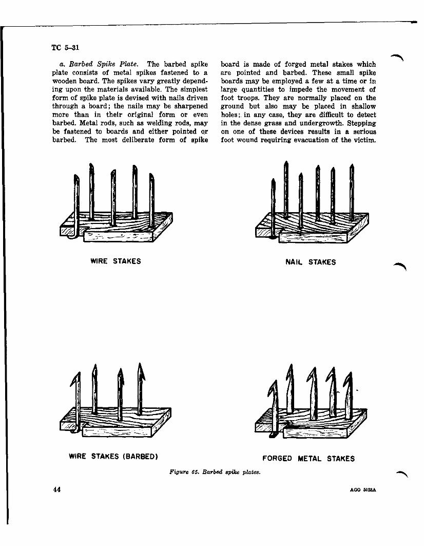
a. Barbed Spike P/,ate. The barbed spike plate consists of metal spikes fastened to a wooden board. The spikes vary greatly depending upon the materials available. The simplest form of spike plate is devised with nails driven through a board; the nails may be sharpened more than in their original form or even barbed. Metal rods, such as welding rods, may be fastened to boards and either pointed or barbed. The most deliberate form of spike
WIRE STAKES
board is made of forged metal stakes which are pointed and barbed. These small spike boards may be employed a few at a time or in large quantities to impede the movement of foot troops. They are normally placed on the ground but also may be placed in shallow holes; in any case, they are difficult to detect in the dense grass and undergrowth. Stepping on one of these devices results in a serious foot wound requiring evacuation of the victim.
NAIL STAKES
WIRE STAKES (BARBED) FORGED METAL STAKES
Figure 65. Barbed spike plate.. ~
44 AGO "2M
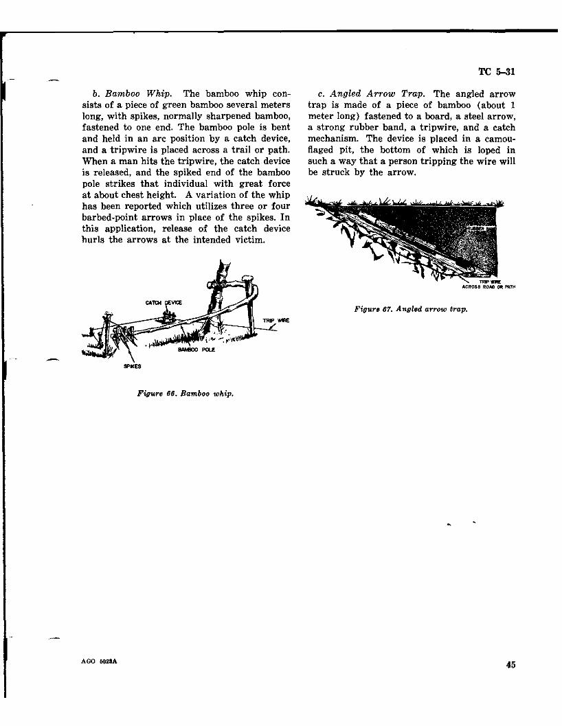
b. Bamboo Whip. The bamboo whip consists of a piece of green bamboo several meters long, with spikes, normally sharpened bamboo, fastened to one end. The bamboo pole is bent and held in an arc position by a catch device, and a tripwire is placed across a trail or path. When a man hits the tripwire, the catch device is released, and the spiked end of the bamboo pole strikes that individual with great force at about chest height. A variation of the whip has been reported which utilizes three or four barbed-point arrows in place of the spikes. In this application, release of the catch device hurls the arrows at the intended victim.
TRP WIRE
- SPl<£S
Figure 66. Bamboo whip.
TC 5-31
c. Angled Arrow Trap. The angled arrow trap is made of a piece of bamboo (about 1 meter long) fastened to a board, a steel arrow, a strong rubber band, a tripwire, and a catch mechanism. The device is placed in a camouflaged pit, the bottom of which is loped in such a way that a person tripping the wire will be struck by the arrow.
Figure 67. Angled arrow trap.
AGO 6028A 45
TC 5-31
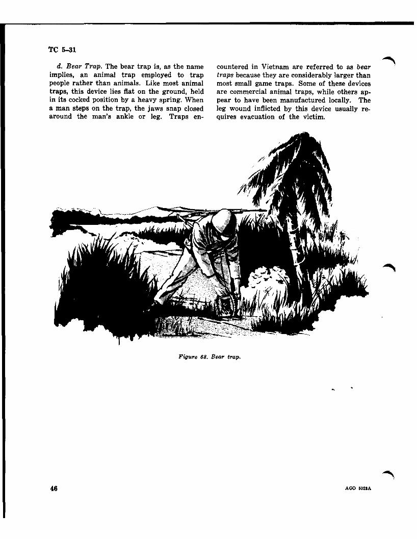
d. Bear Trap. The bear trap is, as the name implies, an animal trap employed to trap people rather than animals. Like most animal traps, this device lies flat on the ground, held in its cocked position by a heavy spring. When a man steps on the trap, the jaws snap closed around the man's ankle or leg. Traps en
countered in Vietnam are referred to as bear traps because they are considerably larger than most small game traps. Some of these devices are commercial animal traps, while others appear to have been manufactured locally. The leg wound inflicted by this device usually requires evacuation of the victim.
Figure 68. Bear trap.
46 AGO i028A
g y e
-
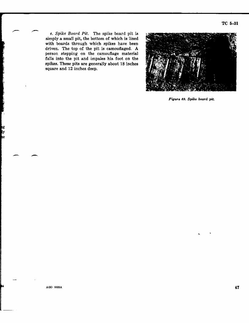
e. Spike Board Pit. The spike board pit is simply a small pit, the bottom of which is lined with boards through which spikes have been driven. The top of the pit is camouflaged. A person stepping on the camouflage material falls into the pit and impales his foot on the spikes. These pits are generally about 18 inches square and 12 inches deep.
-
TC 5-31
Figur. 89. Spike board pit.
AGO 5023A
TC 5-31
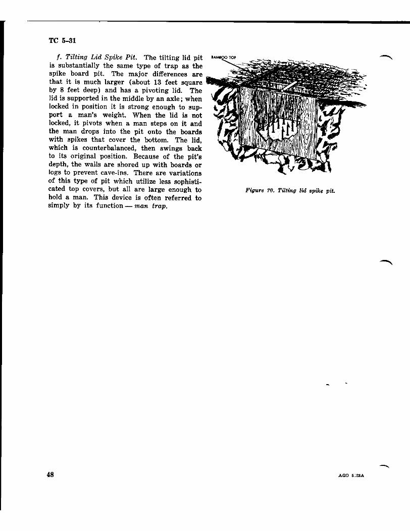
f. Tilting Lid Spike Pit. The tilting lid pit is substantially the same type of trap as the spike board pit. The major differences are that it is much larger (about 13 feet square by 8 feet deep) and has a pivoting lid. The lid is supported in the middle by an axle; when locked in position it is strong enough to support a man's weight. When the lid is not locked, it pivots when a man steps on it and the man drops into the pit onto the boards with spikes that cover the bottom. The lid, which is counterbalanced, then swings back to its original position. Because of the pit's depth, the walls are shored up with boards or logs to prevent cave-ins. There are variations of this type of pit which utilize less sophisticated top covers, but all are large enough to hold a man. This device is often referred to simply by its function - man trap.
BAM800 top
Figure 70. Tilting lid epike pit.
48 AGO 6;28A
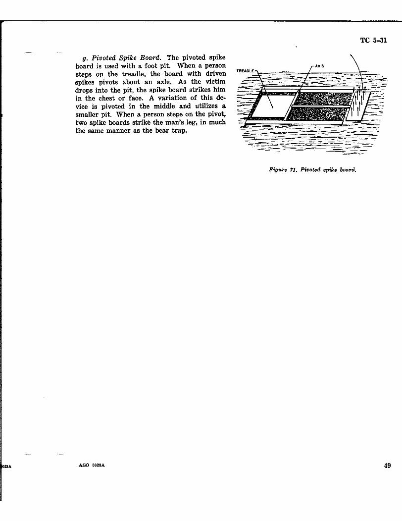
g. Pivoted Spike Board. The pivoted spike board is used with a foot pit. When a person steps on the treadle, the board with driven spikes pivots about an axle. As the victim drops into the pit, the spike board strikes him in the chest or face. A variation of this device is pivoted in the middle and utilizes a smaller pit. When a person steps on the pivot, two spike boards strike the man's leg, in much the same manner as the bear trap.
TC 5-31
'"\-~~ ..-_c;o=.=~ -I....",.,,=~_~..~=.•.~_.=_ ~-
Figure 11. Pivoted spike board.
AGO 5028A 49
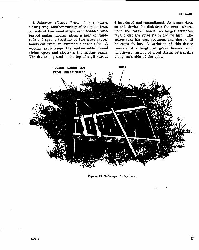
j. Sideways Closing Trap. The sideways closing trap, another variety of the spike trap, consists of two wood strips, each studded with barbed spikes, sliding along a pair of guide rods and sprung together by two large rubber bands cut from an automobile inner tube. A wooden prop keeps the spike-studded wood strips apart and stretches the rubber bands. The device is placed in the top of a pit (about
RUBBER BANDS CUT
TC 5-31
4 feet deep) and camouflaged. As a man steps on this device, he dislodges the prop, whereupon the rubber bands, no longer stretched taut, clamp the spike strips around him. The spikes rake his legs, abdomen, and chest until he stops falling. A variation of this device consists of a length of green bamboo split lengthwise, instead of wood strips, with spikes along each side of the split.
PROP
~.. ,
FROM INNER TUBES
Figure 74. Sideways closing trap.
AGO Ii' 5'1.
TC 5-31
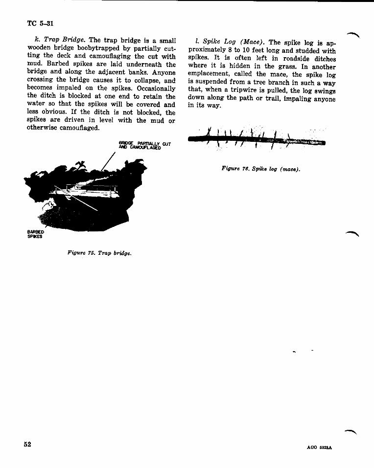
k. Trap Bridge. The trap bridge is a small wooden bridge boobytrapped by partially cutting the deck and camouflaging the cut with mud. Barbed spikes are laid underneath the bridge and along the adjacent banks. Anyone crossing the bridge causes it to collapse, and becomes impaled on the spikes. Occasionally the ditch is blocked at one end to retain the water so that the spikes will be covered and less obvious. If the ditch is not blocked. the spikes are driven in level with the mud or otherwise camouflaged.
~';,CUT
Figure 75. Trap bridge.
I. Spike Log (Mace). The spike log is approximately 8 to 10 feet long and studded with spikes. It is often left in roadside ditches where it is hidden in the grass. In another emplacement, called the mace. the spike log is suspended from a tree branch in such a way that, when a tripwire is pulled. the log swings down along the path or trail. impaling anyone in its way.
Figure 76. Spike log (11UUJ<J).
AGO 6028A 52
m. Spike Ball (Mace). The spike ball consists of a concrete or mortar ball into which spikes are cast. The ball varies in size and weight but may be as much as 24 inches in diameter and weigh 40 pounds or more. The ball is suspended in a tree by a rope, wire, cable, or other suitable line, and as with the log mace, when a tripwire is pulled, the ball swings down along the path or trail, striking anyone in its way.
BARBED SPIKES
CONCRETE BALL
Figure rr. Spike ball (mace).
TC 5-31
n. Suspended Spikes. The suspended spikes device, also known as the tiger trap, consists of a board approximately 18 inches square with spikes. It is weighted with bricks and suspended from the branch of a tree overhanging a path. A tripwire stretched across the path beneath the spike board, when pulled, frees the device to fall on someone below. Size and materials used for this device may vary widely.
Figure 78. SU8pended spikes.
AGO 5023A 53
TC 5-31
SECTION V
MINE WARFARE TECHNIQUES
14. General. It may appear that the Viet Cong do not have a specific warfare doctrine, and inexperienced observers may assume that Viet Cong employment techniques are haphazard and ineffective. Such an evaluation of VC capabilities would be completely erroneous and lead to a false sense of security and tactical errors. The facts of the matter are that the Viet Cong know what they are doing in mine warfare, and they do it well. One of the principal reasons for possible low evaluation of VC techniques is that, unlike U. S. doctrine, they do not employ mines in any standard pattern, and "minefields" are, for all practical purposes, nonexistent. The explanation for this is quite simple; the very nature of the terrain in Vietnam and Viet Cong tactics do not lend themselves to extensive minefields and standard patterns. Therefore, the Viet Cong have adapted the use of mines to the terrain and support of their particular tactical operations. For all intents and purposes, the Viet Cong do have a specific mine doctrine, which in U. S. terms, is nuisance mining in its extreme application. The purpose of this section is to synthesize field reports and observations into techniques of employment of mines and boobytraps by the Viet Congo The first four sections of this circular provide the basic essential data in meeting this objective.
15. Employment of Antitank and Antivehicular Mines. a. Vehicular traffic in Vietnam is, to a large extent, restricted to roads and trails, although this will vary with the season of the year and specific locale. The road network is not extensive, and the roads will not support sustained heavy traffic without constant maintenance. With all of these factors in mind, the Viet Cong employ mines accordingly.
b. Of primary concern is the movement of U. S. troops, supplies, and equipment over both paved and dirt roads, although harassing tactics against single or small groups of ve
hicles is common. Proper placement of one or two mines can, upon initiation, disrupt an entire convoy, immobilize administrative and patrol vehicles, or trigger an ambush. Large numbers of antitank mines need not, and seldom are, employed at anyone location. A few mines can effectively harass and slow vehicular movement; bypass is difficult and often impossible.
C. The Viet Cong utilize both command detonation systems and pressure initiation systems. Although techniques may not be consistent from one area to another, there are indications that command detonated mines are preferred. The advantages of this system are that the VC can choose the time of detonation and the target, and that much of the terrain in Vietnam provides the necessary Cover and concealment for effective employment of command detonated mines.
d. Initiation of command mines can be by electrical means or by pull wires to a pull fuze in the mine. The electrical system is the most common, and it is reasonably simple to install. An electric detonator, usually an electric blasting cap, is installed in the mine, and a firing wire is attached to the detonator leads and extended to the selected firing position. A power source of either a battery, battery pack, or hand-held generator completes the circuit. Firing wires are usually buried deep in the ground both for secrecy and protection. If the wires are either buried shallowly and intermittently, or not buried at all, it is. an indication of a very hasty emplacement. The distances from the mines to the firing positions will vary with the cover and concealment afforded, line of sight from firing position to mine, and even the amount of wire available to the VC at the time. Covered and/or concealed withdrawal routes for the enemies firing the mines are further considerations in selecting firing positions.
--..e. Command mines are initiated by pull wires
AGO 5023A 54
-less frequently than by electrical means; however, any degree of employment of this system warrants consideration. In this application, a pull-friction or other instantaneous pull fuze is installed in the mine, and a pull wire is at tached to the fuze and extended to the firing position. A pull on the wire detonates the mine at the selected time. As with the electricallyinitiated mines, concealment for the firer is required to insure an element of surprise, and cover is more critical because the firer is much closer to the mine. The pull wire is not buried, but it may be camouflaged with leaves, grass, or other material.
f. Placement of mines on roads and trails is rarely haphazard, but techniques may vary depending on the type of road or trail--dirt or paved. One method of mining dirt roads is to dig up one or more sections of the road and leave. After friendly forces fill in the dug-up sections of road, the VC return and mine the filled-in sections. The Viet Cong may dig many holes in a dirt road but only mine a few of them. With all of the filled-in holes appearing to be mined, friendly forces must investigate- each one, resulting in further delay. Most of the time the Viet Cong wish to leave no indication of mining, and any traces of mining dirt roads is easily eliminated. AII dirt roads and trails must be traversed with utmost caution, and frequent reconnaissance should be conducted.
g. Employment of mines on hard surfaced roads presents emplacement problems which are not applicable to dirt roads. This does not deter the Viet Cong from effectively mining paved roads and eliminating most evidence of mining activity. Emplacement of mines in the surface of the road is accomplished by the same techniques as in dirt roads except for covering up traces of mining. One technique is to smear the road with mud in many places day after day but place no mines. Later the VC will lay mines in some mud-smeared sections. Another technique is to dig up the road and layout one or more mines; then they resurface the section of road with similar material and create tire marks and skid marks across the patch to blepd with the rest of the
AGO 502SA
TC 5-31
road. Hastily emplaced mines may merely be covered with straw, grass, dung, or other substance found in the area and likely to be found on the road.
h. A technique commonly employed by the Viet Cong to mine roads is to tunnel under the road from the shoulders. Many roads in Vietnam are constructed on fill, particularly in rice country, and the shoulders are well suited to horizontal excavation. For under-road mining, the Viet Cong utilize large demolition charges, artillery shells, or even bombs, rather than standard land mines. Initiation is by an electrical command firing system. With the road surface undisturbed and electric wires buried, this method of mining is difficult to detect unless there is careful reconnaissance on the shoulders of the road.
i. Regardless of the method employed or the type of road being mined, the Viet Cong rely on hurried or careless mine detecting by U. S. forces. A road found to be clear of mines in the morning may well be mined in the afternoon, or clear one day and mined tbe next. In digging holes or smearing mud on roads and not mining for some period of time, the Viet Cong rely on U. S. troops becoming confident that the road is not mined or neglecting to check every location day after day. Hasty or careless mine reconnaissance by the opposing force is a distinct element of Viet Cong mine warfare doctrine.
16. Employment of Antipersonnel Mines. a. Although antitank mines present a hazard to vehicles on roads and trails, antipersonnel mines present an even greater hazard to foot troops in Vietnam. In spite of vehicular and air movement of troops and supplies, and limited mechanized operations, the vast majority of military operations are conducted on foof; therefore, the incidence of antipersonnel mining by the Viet Cong far exceeds antitank or antivehicular mining. The nature of the terrain and conduct of the war provide almost unlimited techniques for employing antipersonnel mines.
b. As a general rule, the Viet Cong can be expected to employ antipersonnel mines any
55
TC 5-31
where that troops might walk. No area can be assumed to be clear simply because it had been at some previous time. Some of the more likely places of employment are: along trails, in high grass, in front of defensive positions, in and around likely helicopter landing sites, near shaded areas where troops may congregate, at bridges and fording sites over streams and drainage ditches, on rice paddy dikes, along roads at ambush sites, in what appears to be the easy way through dense vegetation, in the vicinity of cave and tunnel entrances, and in and around villages.
c. The Viet Cong may emplace antipersonnel mines by whatever method fits the situation, the terrain, or availability of materiel and equipment. They may place mines in the ground or on the ground; they may fasten them to tree trunks, bushes, or stakes; or they may elevate them to tree branch level to obtain maximum high-burst effect. In addition to variations in methods of emplacement, the Viet Cong select the method of initiation to obtain the best result in light of the situation, terrain, and materials available.' Tripwires are used extensively, particularly across trails and in dense vegetation where the wire is most difficult to detect. Many improvised mines, as well Wl artillery and mortar shells, are initiated by electrical command firing systems in much the same manner as antitank and antivehicular mines. Very few Viet Cong antipersonnel mines are pressure initiated; however, improvised pressure firing devices have been employed in conjunction with explosive charges Wl antipersonnel mines. Tripwires and electrical command firing systems are the most prevalent methods of initiating antipersonnel mines.
d. The Viet Cong utilize all types of material for tripwires. U. S. tripwire is used extensively and is difficult to detect in the dense under. growth. Even more effective, and more extensively used, is a monofilament fishing line type of wire. When these two types of wires are in short supply, the Viet Cong make use of any available material. U. S. communications wire has been used as tripwire as well as for electrical command firing wire. When cutting communications wire, care must be
taken to insure that it is not an electrical installation; cutting both wires simultaneously may detonate the charge. Other materials used by the Viet Cong are 14-inch fiber rope and strips of bamboo and vines. Viet Cong tripwires are skillfully installed and require a sharp eye to detect.
e. A favorite tactic of the Viet Cong is the ambush, and both antitank and antipersonnel mines are used effectively for this purpose. Antitank mines are often used to trigger an ambush by stopping or disrupting a convoy. As troops deploy off the road to attack the ambush force, antipersonnel mines are initiated, adding further confusion to an already tense and difficult situation. Both tripwire and command initiated mines are used; however, Wl in most Viet Cong mining activities, large numbers of mines are not employed. Placement of a few mines is carefully planned to supplement an equally well-planned ambush, and the intended result may be achieved with minimum expenditure of materials and effort.
17. Boobytrap Techniques. Much of the Viet Cong mine warfare doctrine, explicit or implied, involves boobytrapping as opposed to the more defined employment of antitank and antipersonnel mines. Boobytraps can usually be identified as such; however, it is often difficult to distinguish between some explosive boobytraps and a common antipersonnel mine. As a practical matter, it is not so important to be able to distinguish between a boobytrap and a mine as it is to recognize employment techniques, and to detect and counteract such devices. Both mines and boobytraps are designed to inflict casualties, and it makes little difference to a wounded man which one he encountered; he is concerned, however, that he was not able to avoid it in the first place. Viet Cong boobytraps include both explosive and nonexplosive devices, and the extent to which either is employed is limited only by inventive skills and materials available. Both types of boobytraps can be used separately or in conjunction with one another, and the techniques of employment may be identical or may vary considerably. -
AGO ~028A 56
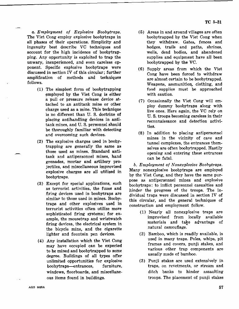
a. Employment of Explosive Boobytraps. The Viet Cong employ explosive boobytraps in all phases of their operations. Simplicity and ingenuity best describe VC techniques and account for the high incidence of boobytrapping. Any opportunity is exploited to trap the unwary, inexperienced, and even careless opponent. Specific explosive boobytraps were discussed in section IV of this circular; further amplification of methods and techniques follows.
(l) The simplest form of boobytrapping employed by the Viet Cong is either apull or pressure release device attached to an antitank mine or other charge used as a mine. This technique is no different than U. S. doctrine of placing antihandling devices in antitank mines, and U. S. personnel should be thoroughly familiar with detecting and overcoming such devices.
(2) The explosive charges used in boobytrapping are generally the same as those used as mines. Standard anti- tank and antipersonnel mines, hand grenades, mortar and artillery projectiles, and miscellaneous improvised explosive charges are all utilized in boobytraps.
(3) Except for special applications, such as terrorist activities, the fuzes and firing devices used in boobytraps are similar to those used in mines. Boobytraps and other explosives used in terrorist activities often utilize more sophisticated firing systems; for example, the mousetrap and wristwatch firing devices, the electrical system in the bicycle mine, and the cigarette lighter and fountain pen devices.
(4) Any installation which the Viet Cong may have occupied can be expected to be mined and boobytrapped to some degree. Buildings of all types offer unlimited opportunities for explosive boobytraps--.mtrances, furniture, windows, floorboards, and miscellaneous items found in buildings.
AGO 5023A
TC 5-31
(5) Areas in and around villages are often boobytrapped by the Viet Cong when they withdraw. Gates, fences and hedges, trails and paths, shrines, wells, dead bodies, and abandoned supplies and equipment have all been boobytrapped by the VC.
(6) Supply areas from which the Viet Cong have been forced to withdraw are almost certain to be boobytrapped. Weapons, ammunitiol\, clothing, and food supplies must be approached with caution.
(7) Occasionally the Viet Cong will employ dummy boobytraps along with live ones. Here again, the VC rely on U. S. troops becoming careless in their reconnaissance and detection activities.
(8) In addition to placing antipersonnel mines in the vicinity of cave and tunnel complexes, the entrances themselves are often boobytrapped. Hastily opening and entering these entrances can be fatal.
b. Employment of Nonexplosive Boobytraps. Many nonexplosive boobytraps are employed by the Viet Cong, and they have the same purpose as antipersonnel mines and explosive boobytraps: to inflict personnel casualties and hinder the progress of the troops. The individual traps were discussed in section IV of this circular, and the general techniques of construction and employment follow.
(1) Nearly all nonexplosive traps are improvised from locally available materials and take advantage of natural camouflage~
(2) Bamboo, which is readily available, is used in many traps. Poles, whips, pit frames and covers, punji stakes, and various other trap components are usually made of bamboo.
(3) Punji stakes are used extensively in traps, on revetments, or stream and ditch banks to hinder assaulting troops. The placement of punj i stakes
57
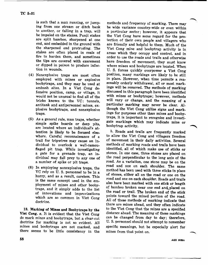
TC 5-31
is such that a man running, or jumping from one stream or ditch bank to another, or falling in a trap, will be impaled on the stakes. Punji stakes are split bamboo, sharpened at one end, and embedded in the ground with the sharpened end protruding. The stakes are often placed in coals of fire to harden them, and sometimes the tips are covered with exerement or dipped in poison to produce infection in wounds.
(4) Nonexplosive traps are most often employed with mines or explosive boobytraps, and they may be used at ambush sites. In a Viet Cong defensive position, camp, or village, it would not be unusual to find all of the tricks known to the VC: tunnels, antitank and antipersonnel mines, explosive boobytraps, and nonexplosive traps.
(5) As a general rule, man traps, whether simple spike boards or deep pits, are located where an individual's at tention is likely to be focused elsewhere. Careful reconnaissance of a trail for tripwires may cause an individual to overlook a well-camouflaged pit trap. While investigating a gate for a grenade trap, an individual may fall prey to anyone of a number of spike or pit traps.
(6) In employing nonexplosive traps, the VG rely on U. S. personnel to be in a hurry, and as a result, careless. This is the same concept used in the employment of mines and other boobytraps, and it simply adds to the list of innovations and improvisations which are so common in Viet Gong doctrine.
18. Marking of Mines and Boobytraps by the Viet Congo a. It is evident that the Viet Gong do mark mines and boobytraps, but a clear-cut doctrine for marking is not so evident. All mines and boobytraps are not marked, and there seems to be little consistency in the
methods and· frequency of marking. There may be wide variance country-wide or even within a particular sector: however, it appears that the Viet Gong have some regard for the protection of their own people and villagers who are friendly and helpful to them. Much of the Viet Gong mine and boobytrap activity is in areas which they occupy and control, and in order to use the roads and trails and otherwise have freedom of movement, they must know where mines and boobytraps are located. When U. S. forces quickly overpower a Viet Gong position, many markings are likely to be still in place. However, when time permits a reasonably orderly withdrawal, all or most markings will be removed. The methods of marking discussed in this paragraph have been identified with mines or boobytraps; however, methods will vary or change, and the meaning of a particular marking may never be clear. Although the Viet Gong utilize signs and markings for purposes other than mines and boobytraps, it is important to recognize and investigate markings which may indicate mine or boobytrap activity. ...........
b. Roads and trails are frequently marked to allow the Viet Gong and villagers freedom of movement in their daily activities. Several methods of marking roads and trails have been identified, all of which make use of sticks or stones. In one case, three stones are placed on the road perpendicular to the long axis of the road. As a variation, one stone may be on the road and one on each shoulder. The same method has been used with three sticks in place of stones, either all on the road or one on the road and one on each shoulder. Roads and trails also have been marked with one stick or length of bamboo broken near one end and,placed on the road or trail. The broken end of the stick points toward the mined portion of the road. All of these methods of marking indicate that there are mines ahead, and they often indicate to the Viet Gong that the mines are a specified distance ahead. The meaning of these markings can be changed from day to day; therefore, U. S. personnel should not attempt to remember specific meanings, but be especially alert for mines from that point on. _
AGO IOIlA 58
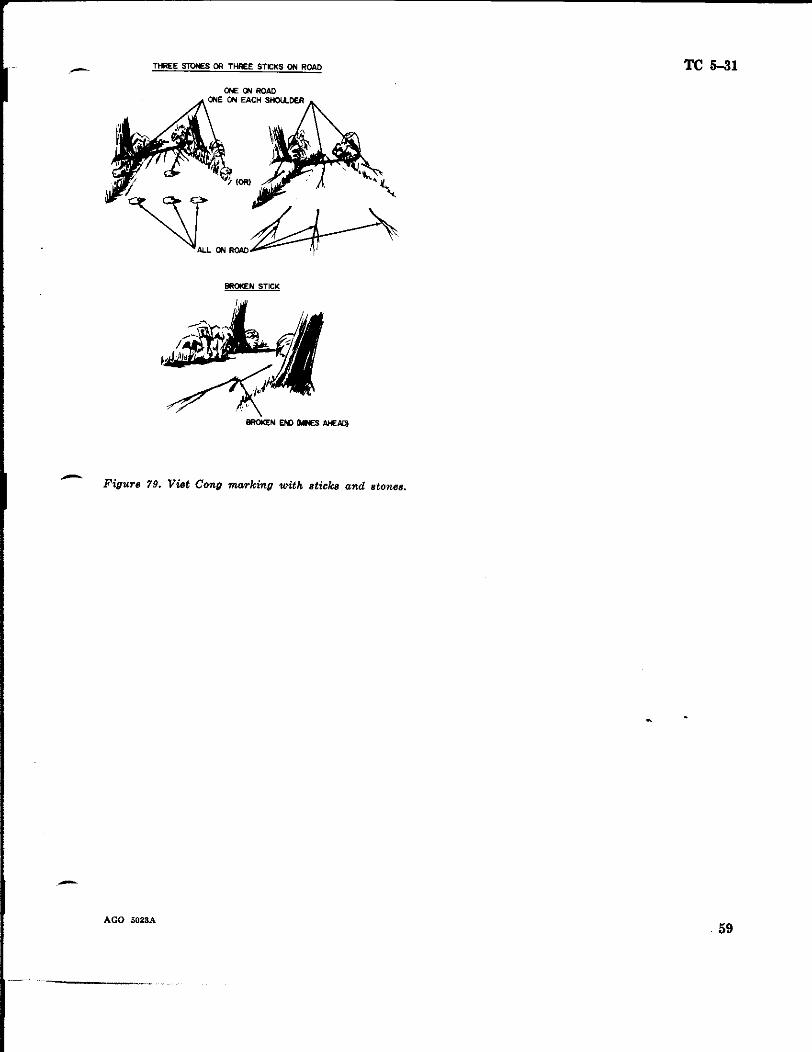
THREE STONES OR THREE STICKS ON ROAD TC 5-31
BROI<EN STICK
Figure 79. Viet Cong marking with sticks and stones. -
-AGO 5028A
59
TC 5-31
c. The location of mines may be more closely marked by other methods, two of which are illustrated in figure 80. One method is to place two small sticks in the ground vertically and lash a third stick horizontally to the other two in the form of a "goal post." This type of marker usually means that there are mines in the immediate area. The second marker consists of clumps of grass tied together at the four corners of a 2-meter square. The mine is placed in the middle of the square.
METHODS OF VC MARKING
Figure 80. Viet Gong marking-"goal post" and grass.
d. Boobytrapped dwellings, caves, and tunnels have also been found to be marked. From one to three pieces of string are placed at or above the entrances denoting that the installa
tions are boobytrapped. There is no regularity as to length or type of string, and material of any color can be used. As with most markings, the strings are inconspicuous to the casual observer but apparent to the VC and others who know what to look for.
STRINGS
STRING OVER DOORWAY
ONE, TWO. OR THREE STRINGS HUNG OVER ENTRANCES TO DWELLINGS, CAVES. TUNNELS (INSTALLATION MINED AND/OR BOOBYTRAPPED)
STRING MAY BE ANY MATERIAL AND ANY COLOR USUALLY SHORT 2" TO 12"
Figure 81. Viet Gong marking with string.
e. The Viet Cong also use signs to mark the presence of mines or boobytraps,~but there is no evidence of standard signs as in U. S. doctrine. The signs encountered thus far have been crudely assembled on a variety of materials with a variety of words (fig. 82). These signs, fabricated of paper, cloth, wood, or metal, are obviously made in the field, if not on the spot, and they are probably not intended for longterm use. As with marking with objects, the siuns anllarently have specific meanings to the local Viet Cong; however, U. S. personnel
AGO 5028A 60
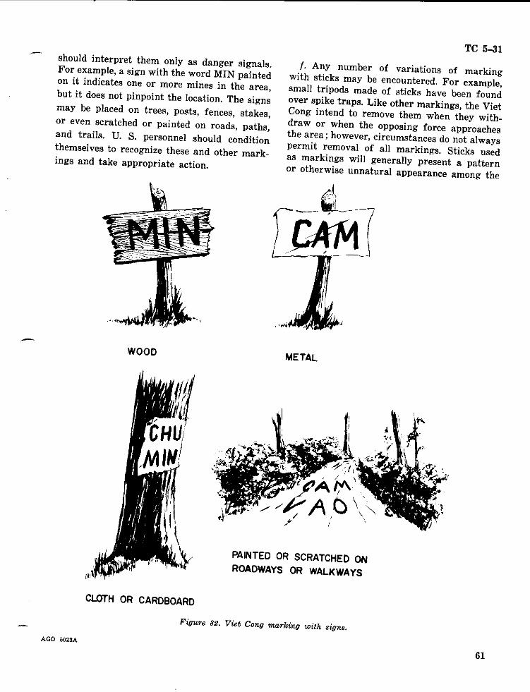
TC 5-31 should interpret them only as danger signals. For example, a sign with the word MIN painted on it indicates one or more mines in the area, but it does not pinpoint the location. The signs may be placed on trees, posts, fences, stakes, or even scratched or painted on roads, paths, and trails. U. S. personnel should condition themselves to recognize these and other markings and take appropriate action.
j. Any number of variations of marking with sticks may be encountered. For example, small tripods made of sticks have been found over spike traps. Like other markings, the Viet Cong intend to remove them when they withdraw or when the opposing force approaches the area; however, circumstances do not always permit removal of all markings. Sticks used as markings will generally present a pattern or otherwise unnatural appearance among the
WOOD METAL
PAINTED OR SCRATCHED ON ROADWAYS OR WALKWAYS
CLOTH OR CARDBOARD
Figure 82. Viet Cong marking with signs.
AGO 5023A
61
;
TC 5-31
natural vegetation and can be detected by care on the grenade body. Red, green, and white ful observation. dots have been used, and there appears to be
g. Hand grenades, employed as boobytraps, no set color pattern as long as the grenade is from which the delay element has been removed, identifiable to the Viet Cong as instantaneous. have been found marked with a dot of paint
AGO 502M ., 62
TC 5-31
SECTION VI
DEFENSE AGAlNST VIET CONG MINES AND BOOBYTRAPS
19. General. In spite of the high incidence of mine and boobytrap activity by the Viet Cong and their ingeneous methods and techniollPs. U. S. personnel can learn to combat such tactics through proper training and strict application in the field. The Viet Cong are not illl"uw,e; they do make mistakes, and the materiel used in mine and boobytrap activities is rarely 100 percent reliable. As discussed in previous sections of this circular, the Viet Cong rely on hasty and careless methods by U. S. forces, and if this condition exists, the Viet Cong will achieve a high degree of success. There is no room for careless mistakes in mine warfare, and every soldier must be familiar with the precautions and methods of defending himself and his unit against mines and boobytraps. Understanding what the Viet Cong employ as mines, fuzes, explosives, and boobytrap devices, and the methods and techniques of employment, proper defensive measures can -be developed. They must, however, be diligently applied in the field to be of any value. This section includes the defensive measures which will not only reduce Viet Cong effectiveness but will reduce U. S. casualties and lead to greater overall efficiency.
20. General Precautionary Measures. Subsequent paragraphs deal with detection and search techniques, disarming methods, clearing non-explosive traps, and reporting. However, there are important precautions applicable to individuals and/or units which do not properly fall under any of these headings. Some precautionary measures apply under any conditions of mine warfare, while others apply more specifically to operations in Vietnam.
a. The first important precaution is to prevent U. S. materiel and equipment from falling into the hands of the Viet Cong which inevitably will be used against U. S. forces. From ports of entry to the most remote battle areas, the Viet Cong make every effort to obtain U. S. materiel and equipment, and much of this can
AGO 5023A
be prevented by proper safeguards and policing of the battle area. Little can be done by individual soldiers to prevent the Viet Cong from picking up artillery and mortar dud shells, but they can prevent littering the battle area with discarded hand grenades, ammunition, mines, and other items which the Viet Cong may convert to their own use in mine and boobytrap activities.
b. Local commanders should establish and maintain safe intervals in the movement of troops and vehicles as the situation dictates. The effect of many antipersonnel mines and most hand grenades employed by the Viet Cong is such that more than one individual will become a casualty within the effective casualty radius. Well-placed antitank or antivehicular mines can be equally effective against vehicles in convoy which follow too closely. Viet Cong success in mine warfare can be drastically reduced by the simple application of good discipline in the movement of troops and vehicles.
c. Wheeled and tracked vehicle operators should be instructed to "track" the vehicle ahead when that vehicle is in sight. This will reduce the possibility of detonating a pressure activated mine which the vehicle ahead may have missed. On the other hand, old tracks should be avoided if possible, because the Viet Cong commonly place mines in old tracks.
d. Although U. S. soldiers are eager to go to the aid of fellow soldiers who have become mine casualties, they should do so with caution. Secondary mines or boobytraps are often emplaced for just such purpose~
e. Battle successes are often achieved through rapid and violent attack maneuvers, and without suggesting a sacrifice of speed, it must be tempered with caution. Speed often generates carelessness, and this is what the Viet Cong rely on in their employment of mines and boobytraps.
,. The ftooring of vehicles should be sandbagged to provide protection for mounted per
63
TC 5-31
sonnel. Personnel riding in vehicles must keep arms and legs inside vehicle so as to achieve maximum protection from sandbags. As an additional recommended precaution, a heavy rubber mat should be placed over the sandbags to reduce fragments such as stones, sand, shrapnel, and pieces of bag. To further reduce the possibility of fragments, sandbags should not be filled with rocks or sand with rocks in it.
g. The speed and spacing of individual vehicles can be varied so as to make the timing of command detonated mines more difficult.
h. Key personnel, who are prime targets for command initiated mines, must not congregate in one vehicle but be dispersed throughout the column.
i. Whenever possible, vehicles should avoid traveling singly as they may be targets for Viet Cong seeking weapons and other equipment.
21. Detection and Search Techniques. Detection of mines and boobytraps in Vietnam is difficult and laborious and requires careful observation. The degree of difficulty and detection efficiency can be improved considerably if individuals know what to look for and where to look. Some individuals and small units, such as patrols and mine detection teams, will be engaged in deliberate search operations; however, most troops must be trained to detect mines and boobytraps in the normal course of daily activities. Units that have been actively engaged in Vietnam, some since the beginning of U. S. involvement, have gained valuable, and often costly, experience. Fortunately, new units and individuals can profit by these experiences and be better prepared to perform their missions in an unfamiliar environment.
a. Following are recommended methods and techniques of detecting the presence of mines and boobytraps in Vietnam:
(1) Be especially alert for tripwires across trails; along the shoulders of roads at likely ambush sites; in the vicinity of known or suspected antitank or antivehicular mines; across the most accessible route through dense vege
tation; at the approaches to and within villages; in and around likely helicopter landing sites; at the approaches to VC positions; at bridges, fords, and ditches; across rice paddy dikes.
(2) Look for mud smears, grass, sticks, dirt, dung, or other substances on roads; many of these areas will be mined.
(3) Look for evidence of apparent road repair-new fill or paving, road patches, ditching, or culvert work; such areas often conceal mines.
(4) Avoid tire marks, ruts, or skid marks on roads; these areas may conceal mines and should be investigated.
(5) Be alert for any signs placed on trees, posts, or stakes, or painted on roadways. Most of these signs are small and inconspicuous, and although all of them do not indicate the presence of mines, they should be investigated.
- (6) Watch for markings, other than signs, which are used by the Viet Cong to mark mines and boobytraps. These markings are even less conspicuous than signs, but they appear as a regular pattern not present in nature : sticks or stones in a line; a broken stick carefully placed on a road or trail; clumps of grass at regular intervals; sticks placed in the ground in an unusual manner; or innocentlooking strings hanging over a doorway.
(7) Watch for wires leading away from the side of a road. Although the Viet Cong usually bury comnmnd /Iring wires, some may be only partially buried or not buried at all.
(8) Be alert for any suspicious item in trees, branches, or bushes; these may be hand grenades, mortar or artillery rounds. Tripwires placed across a trail may be difficult or impossible to detect; but the charge, which Is usually placed alongside of the trail
AGO Ii028A 64
or overhead, may be more readily apparent.
(9) Watch for any feature of the terrain which does not appear to be natural. The Viet Cong are very adept at camouflaging traps and pits; however, after a short period of time, the appearance of the installation often changes, if only slightly. Uprooted and cut vegetation dries and changes color; rain may wash away some of the material placed over pit covers; excessive material on pit covers may cause them to sink, leaving a depression or crack around the edges; tops of pits and traps may appear as unusual mounds of a uniform dimension.
(10) Observe the movements of civilians, particularly in areas that have been occupied by Viet Cong. The civilians usually know the locations where most mines and boobytraps have been placed in and around their villages,
- and they avoid these areas. They may walk on one side of a road, avoiding the other side; they may walk in the middle of a road, avoiding the sides and shoulders; or they may avoid a road entirely. If civilians do not use certain buildings or facilities in the village, it is a good sign that they are mined or boobytrapped.
.(11) Viet Cong flags, banners, and miscellaneous VC supplies and equipment are frequently boobytrapped, and they should be investigated.
(12) Nonexplosive traps which are placed at or above ground level are usually well camouflaged but may be detected by careful observation. Spike board plates may be partially concealed in the grass, but the spikes are straight as compared to the irregular pattern of the grass, and if nails or wire are used as spikes, they may shine in the sun. The bamboo whip is emplaced horizontally and presents a smooth arc in its cocked position; careful
AGO 5023A
TC 5-31
observation will detect this device among the common irregular and vertical vegetation. The log and ball mace, and suspended spikes are of such size and configuration as to appear unnatural among tree branches; however, careful observation overhead is required to detect these devices.
(13) Pieces of wood (boards or bamboo) on a road may indicate the presence of pressure firing devices for antitank or antivehicular mines. These devices are either placed on the surface of the road or partially buried, and in either case, they are usually camouflaged. Hasty emplacement or weather conditions often reduce the effectiveness of the camouflage to the extent that the devices may be detected by careful observation. Vehicle operators should be cautioned against carelessly driving over wood, sticks, or other debris on a road.
(14) Be alert for the sound of an exploding cap in a delayed fuze device.
b. Search techniques are similar to the detection techniques discussed in the previous paragraph; however, in the context of this circular, search denotes a more deliberate action by individuals, teams, or small units in locating mines and boobytraps as compared to detection by all personnel in their daily activities. In listing search techniques, all of the detection techniques previously discussed would obviously head the list; however, they are not repeated here except as clarification when required.
(1) In addition to observing movement of civilians, they should be questioned to determine specific locations of mines and boobytraps.
(2) Suspicious imprints, marks, or debris on roads should be investigated visually, by probing, or with mine detectors as appropriate.
(3) Investigate all gates for boobytrapping with hand grenades or other explosive devices.
65
TC 5-31
(4) Visually inspect and probe trails, paths, and other routes through dense vegetation for tripwires.
(5) Carefully observe overhead and to the flanks of a route through dense vegetation for hand grenades, shells, and other devices or traps placed either on the ground, in bushes, or in trees.
(6) Investigate all Viet Cong flags, banners, and abandoned supplies and equipment for boobytraps.
(7) Investigate entrances to caves, tunnels, and buildings of all kinds for boobytraps, and search the approaches to and vicinity of these facilities for antipersonnel mines.
(8) Investigate any unnatural appearance of the terrain for possible traps and pits.
(9) Visually inspect and probe antitank and antivehicular mines for anti handling devices.
(10) Investigate potential souvenir items for boobytraps (firearms, knives, binoculars, uniforms, and miscellaneous items of clothing and equipment).
(11) Conduct reconnaissance of bridges, drainage ditches, and streams, to include both banks, for mines and traps of any kind.
(12) Conduct reconnaissance along the flanks of roads for command firing wires and antipersonnel mines.
(13) Investigate in the vicinity of suspicious signs and other markings which may indicate the presence of mines and boobytraps.
(14) Investigate the interior and contents of any building suspected of being boobytrapped by the Viet Congo Although most structures in the villages are of no military use to U. S. forces, they must be searched for VC personnel, supplies, equipment, tunnel entrances, and other items or information of military value; there are many opportunities for boobytrapping.
(15) With the high incidence of commandinitiated mines, route clearance requires some special precautions and procedures. Road shoulders and adjacent areas should be searched and cleared first to insure that potential firing positions, firing wires, and boobytraps are eliminated; then the road can be cleared with some degree of safety. Buried firing wires can be exposed and cut by single-toothed rooters operating parallel to and 10 to 50 meters from the road. There must be adequate security for route clearing parties who are occupied with the clearance task and exposed to attack by the Viet Congo
22. Disarming Methods. The first essential steps in defending against Viet Cong mines and boobytraps are detection and recognition of mined and boobytrapped areas or facilities and location of the devices. Once this is accomplished, the safest procedure is to avoid or bypass these areas or facilities; however, it is seldom tactically possible or feasible to do so. ~.The momentum of the attack must be main !
tained, and although some mines and boobytraps can be bypassed temporarily, most of them must be dealt with immediately. Trained personnel with the attacking forces can render most mines and boobytraps safe to allow passage of troops and vehicles, while EOD teams and other specially trained personnel can completely neutralize these devices as well as those which may have been bypassed as being too dangerous to handle. Complete neutralization of an explosive device is a highly skilled technique requiring specially trained personnel. It is not the intent of this circular to make specialists of its users; it is the intlmt to' provide fundamental guidance in the neutralization procedures which can be followed by troops in the field.
a. Neutralization. Neutralization, the making of a mine or boobytrap safe to handle, involves two steps: Disarming or replacing safeties in the firing assembly; and defuzing or separating the firing assembly from the main charge and the detonator from the firing assembly. If
AGO 5023A 66
TC 5-31
neutralization is not possible, the device must be destroyed.
b. Destrw;tion in Place. A mine or boobytrap may be destroyed in place if some damage is acceptable and if the tactical situation permits. Antipersonnel mines and boobytraps out of doors are usually destroyed in place with no adverse effects. The device can be initiated by its own mechanism and riggings, or by detonating an explosive charge adjacent to the mine or boobytrap. In any case, all personnel must be in a covered position and/or at a safe distance. Antitank mines emplaced in a road can often be destroyed in place if the damage will not seriously impair vehicular traffic; however, charges placed under a road are often of such size that detonation would create an appreciable obstacle. Charges placed on bridges, in built-up areas, and indoors usually must be removed rather than destroyed in place.
c. Removal of the Main Charge. Before attempting removal, careful probing around the main charge is necessary to locate and neutralize antihandling devices. To avoid casualty, the type of firing mechanism must be identified and all safety devices must be replaced. If complete neutralization seems doubtful, the charge should be pulled from place by a grapnel or rope from a safe location. After pulling the charge, personnel should wait at least 30 seconds as a safeguard against a concealed delay action fuze. Use of the grapnel is recommended for most Viet Cong mines and boobytraps which are largely improvised with fuzes and firing devices having no safeties.
d. Hand Disarming. None but trained specialists should attempt hand disarming, unless the mine or boobytrap's characteristics and disarming techniques are well known. Trained specialists only should inspect and destroy all unusual or complicated devices. Particularly dangerous are devices equipped with chemical fuzes. dud mortar and artillery shells. hand grenades, and such boobytraps as the bicyle.
. cigarette lighter, and fountain pen. When hand disarming is necessary, the following procedures should be used for guidance only, as the exact sequence depends on the type of device and manner of emplacement.
AGO 5023A
(1) Do not touch any part of a mine, boobytrap, or other explosive charge without first examining it thoroughly. Locate all firing devices and their triggering mechanisms.
(2) When tracing wires, look for concealed intermediate devices laid to impede searching and clearing. Do not disturb any wires while examining the explosive device.
(3) Cut loose tripwires only after careful examination of all connecting objects and after replacing all safeties.
(4) Trace all taut wires and disarm all connected firing devices by replacing safeties. Taut tripwires should be cut only after eliminating the danger at both ends.
(5) Replace safeties in all mechanisms, using nails, lengths of wire, cotter pins, and other similar objects.
(6) Never use force in disarming firing devices.
(7) Without disturbing the main charge, cut detonating cord or other leads between the disarmed firing device and main charge.
(8) Cut wires leading to an electrical detonator--one at a time.
(9) When using a probe, push it gently into the ground. Stop pushing when the probe strikes any object. (It may be a pressure cap or plate.)
(10) Once separated, mine or boobytrap components should be removed to a safe storage or disposal area.
e. Special Precautions.
(1) Be very cautious -in hlmdling delay mechanisms. Such devices should be destroyed in place or marked for treatment by specialists.
(2) Be extremely cautious with hand grenade boobytraps. Most are set to detonate at the slightest provocation, and the delay element is often removed. Destruction in place is recommended.
67
TC 5-31
(3) Wood, cardboard, or similar explosive of impact. The devices can then be destroyed containers, buried for long periods of or disposed of as directed. time, are dangerous to disturb. They are also extremely dangerous to probe if in an advanced state of decomposition. Deteriorated high explosives are especially susceptible to detonation. Destroy in place.
(4) Explosives containing picric acid are particularly dangerous; from contact with metal, deterioration forms extremely sensitive salts which are readily detonated by handling.
(5) Certain types of fuzes become extremely sensitive to disturbance after exposure to wet soil. Detonation in place is the only safe method of neutralizing or removing such deteriorated fuzes.
23. Clearing Nonexplosive Traps. In addition to explosive boobytraps and mines, nonexplosive traps must be cleared. Although there is no specific doctrine for clearing or neutralizing these traps, many of the procedures and precautions for neutralizing explosive devices can be applied.
a. Be alert for other mines and boobytraps in the area, and insure that individual traps are not further boobytrapped.
b. If traps must be bypassed, they should be clearly marked or guarded for the safety of friendly personnel following.
c. Spike boards and other loose spike devices, and bear traps, which have been sprung from a safe distance, should be picked up and disposed of in order to prevent further use by the Viet Congo
d. Spike (man) traps should be carefully exposed to reveal the configuration and details of construction. They should then be dismantled and the pits filled in.
e. Extreme caution must be exercised in clearing oc neutralizing tripwire actuated traps, such as the mace (log or ball), angled arrow trap, suspended spikes, and bamboo whip. After personnel have been cleared from the area, these devices can be actuated by grapnels from a safe position to the side or rear of the point
24. Reporting. a. A standard enemy minefield reporting procedure as outlined in FM 20-32 is not completely appropriate for operations in Vietnam, but this does not negate the importance of reporting Viet Cong mines and boobytraps. FM 20-32 states that any knowledge or suspicion of the existence of any enemy minefield must be reported to the next higher comman(! immediately. Although it may not be possible to identify Viet Cong minefields as such, the presence of mines and boobytraps, either singly, along a route, or in a general area, must be reported to the next higher command as readily as if a major minefield had been encountered.
b. Immediate concern is by the person or persons who first encounter a mine or boobytrap and against whom the initial casualties may be inflicted. The small unit, squad or platoon, have a vital and immediate personal and tactical interest in the incident and take appropriate countermeasures. However, mine and boobytrap activities involve a much wider sphere of tactical consideration than the squad or platoon. Small unit tactics are part of a larger scheme of maneuver; therefore, the existence of enemy mines and boobytraps must be reported to company, battalion, and higher levels of command for planning, direction, or assistance as required. The information is disseminated laterally to other friendly units for any adjustment to their plans that may be necessary.
C. Division, corps, field army, or other major commands planning future operations are vitally concerned with Viet Cong mine and boobytrap activities, and timely apd accurate reports from the field provide the necessary data. Collection of individual, and sometimes isolated, incidents can, through intelligence production procedures, reveal valuable information. Of primary concern are the locations of mine and boobytrap incidents; the frequency and intensity of activity; the degree of mine and boobvtrap activity against civilians as compared to military application; the correlation between the use of mines and boobytraps
AGO 5028A 68
and Viet Cong tactics; and the quantity and types of hardware currently employed by the Viet Congo
d. Reports of Viet Cong mine and boobytrap activities provide an important technical intelligence tool which not only benefits the higher echelons of the intelligence system but the using units as well. Dissemination of mine and boobytrap information, other than initial reports, cannot be accomplished effectively between units in the field. Such an attempt results in erroneous, inaccurate, incomplete, or invalid data, and an inevitable lack of consistency. Reports must be forwarded up to a point of synthesis where information can be evaluated and assembled into usable intelligence data and then disseminated to all units concerned. Troops in Vietnam must know the types of mines and boobytraps being employed by the Viet Cong, the manner in which they are employed, and recommended countermeasures. This can only be accomplished by an effective reporting system.
e. Detection and the initial collection effort - are accomplished by troops in contact with the Viet Cong, and every effort should be made to open information channels to explosive ordnance disposal (EOD) teams and other technical intelligence units. EOD teams are available to disarm, inspect, destroy, or otherwise process mine and boobytrap items through their channels. The Standing Operating Pro-
TC 5-31
cedure (SOP) of each unit should clearly define reporting procedures to insure completeness, accuracy, and conformity to the SOP of the entire command. A well-planned and executed mine and boobytrap SOP will insure the collection, processing, and dissemination of information as well as the proper disposition of mine and boobytrap hardware.
f. The destruction in place of mines and boobytraps should not go unreported; they should be reported by number, type, location, and circumstances under which they were destroyed. When possible, photographs and sketches should be made before destruction and forwarded through intelligence channels in accordance with the SOP. In some commands this information may appear in the Intelligence Summary (INTSUM). Progress reports should be submitted on route clearing- operations at intervals specified in the SOP; many units include this information in a Daily Situation Report (SITREP).
g. No mine or boobytrap incident should be considered too small or inappropriate to be reported; what may appear to be routine and repetitious to one unit may be of great significance to others. Training literature and training programs concerned with enemy tactics, techniques, and equipment are based on reports from many sources, and any breakdown in the reporting system will ultimately reduce the efficiency of the army in the field.
AGO &QUA 69
TC 5-31
By Order of the Secretary of the Army:
Official : KENNETH G. WICKHAM, Major General, United StateB Army, The Adjutant General.
Distribution: ActivB Army:
ACSI (2) DCSPER (2) DCSLOG (2) DCSOPS (2) CORC (2) CRD (1) COA (1) CINFO (1) TIG (1) CofEngra (2) CNGB (2) USACDCEA (2) USACDCARMA (2) USACDCARTYA (2) USACDCCARMSA (2) USACDCIA (2) USACDCSWA (2) USCONARC (5) USACDC (2) ARADCOM (2) LOGCOMD (5) OS Maj Comd (5) USARSTRIKE (2) MDW (1)
HAROLD K. JOHNSON, General, United States Army, Chief of Staff.
Armies (25) Corps (15) Diy (10) DiY Arty (5) Bde (5) Regt/GP (5) Bn (15) USACDCSWCAG (2) USACDCCAG (2) Sye Colleges ~2)
Br Sye Seh (10) except USAES (50)
TJAGSA (1) USMA (1) USAFSTC (2) USAINTC (2) PMS Sr Diy Units (1) USATC (20) except
UsATC Engr (50) Units org under fol TOE:
5-127 (2) 5-137 (2)
5-500 (IG, KA, KB, KC) (1)
NG: State AG (3); units-eame as active Army except allowance is one copy to each unit. USAR: Units--same as active Army except allowance is one eopy to each unit. For explanation ot above
abbreviations used, see AR 320-50.
'It U.s. OOVDNKENT PRINTING OrPlCII, 1"7- ......I/..28A
'}' 'II( ,
,C 5-31 VIET CONG BOOBYTRAPS, MINES AND MINE WARFARE TECHNIQUES-1967 ~
,