Embed Size (px)
Citation preview

NT12-5042, 1.0, 4/10/2012, Item Number: ISI-4421-0059-PRINT REV A
TC-1520E Equipment Case User’s Manual

NT12-5042, 1.0, 4/10/2012, Item Number: ISI-4421-0059-PRINT REV A
© Ascom 2012. All rights reserved.
TEMS is a trademark of Ascom. All other trademarks are the property of their respective holders.

NT12-5042, 1.0, 4/10/2012, Item Number: ISI-4421-0059-PRINT REV A
Contents
1 Introduction 1
1.1 Safety instructions ............................................................................................................. 2
2 Overview of the TC-1520E 3
2.1 Overview of Function ........................................................................................................ 3
2.2 Devices Compatible with the TC-1520E ........................................................................... 3
2.2.1 Phones .............................................................................................................................. 3
2.3 TC-1520E Compatibility with TEMS Investigation ............................................................. 3
2.4 Using the TC-1520E with TEMS Investigation .................................................................. 4
3 Unpacking the TC-1520E System 4
3.1 TC-1520E System Contents ............................................................................................. 4
3.2 Charging the Internal Battery ............................................................................................ 4
4 TC-1520E Component Details and Functionality 5
4.1 Input Power ....................................................................................................................... 5
4.1.1 Main Input Power Connector ............................................................................................ 5
4.1.2 Auxiliary Power Socket ..................................................................................................... 5
4.2 Internal USB Hubs ............................................................................................................ 6
4.3 Uninterrupted Power Supply (UPS) .................................................................................. 6
4.4 UPS Output Protection Fuse ............................................................................................. 7
4.5 Internal Power Panel (12 V DC) ........................................................................................ 7
4.6 Phone Power Panel .......................................................................................................... 7
4.7 USB to RS-232 Port .......................................................................................................... 7
4.8 Power Distribution Board Fuse ......................................................................................... 8
4.9 System Power Indicator .................................................................................................... 8
4.10 Power Connector Pin Assignments ................................................................................... 9
4.10.1 Main Input Power Receptacle ........................................................................................... 9
4.10.2 Internal Device Power (12 V DC) ...................................................................................... 9
4.10.3 Phone Power Connectors ................................................................................................. 9
4.10.4 Legacy 12 V DC Power Connectors ............................................................................... 10
4.10.5 Cigarette Lighter Socket ................................................................................................. 10
4.11 Phone Cradle Mounting Patterns .................................................................................... 10
4.12 Locking the TC-1520E Case ........................................................................................... 10
5 Vehicle Installation 11
5.1 Seat Mounting Kit ............................................................................................................ 11
5.1.1 Adaptation for Right-Hand Driven Vehicles .................................................................... 12
5.2 System Power Cable ...................................................................................................... 13
5.3 TC-1520E USB Interface ................................................................................................ 13

NT12-5042, 1.0, 4/10/2012, Item Number: ISI-4421-0059-PRINT REV A
6 Shipping the TC-1520E System 14
7 TC-1520E Specifications 14
8 Regulatory Qualifications 15

NT12-5042, 1.0, 4/10/2012, Item Number: ISI-4421-0059-PRINT REV A 1
1 Introduction This manual describes the contents, installation, and functionality of the TC-1520E equipment case.
Note: The product warranty is void if the TC-1520E equipment case and its components are opened in any way other than mentioned in this Installation Guide, or if any seal or label is disturbed.
Warning! System contains batteries. There is a risk of explosion if battery is replaced by an incorrect type. Dispose of batteries according to the manufacturer’s instructions.
Only trained technicians may open and service the TC-1520E equipment case components. For maintenance or repairs please contact Ascom Customer Service at:
Phone: +1 855-323-5755
Email: [email protected]
Web address: http://www.ascom.com
2 NT12-5042, 1.0, 4/10/2012, Item Number: ISI-4421-0059-PRINT REV A
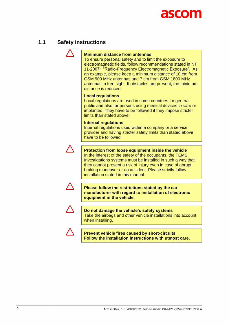
1.1 Safety instructions
Minimum distance from antennas To ensure personal safety and to limit the exposure to electromagnetic fields, follow recommendations stated in NT 11-20071 “Radio-Frequency Electromagnetic Exposure”. As an example, please keep a minimum distance of 10 cm from GSM 900 MHz antennas and 7 cm from GSM 1800 MHz antennas in free sight. If obstacles are present, the minimum distance is reduced.
Local regulations Local regulations are used in some countries for general public and also for persons using medical devices in-vitro or implanted. They have to be followed if they impose stricter limits than stated above.
Internal regulations Internal regulations used within a company or a service provider and having stricter safety limits than stated above have to be followed
Protection from loose equipment inside the vehicle In the interest of the safety of the occupants, the TEMS Investigations systems must be installed in such a way that they cannot present a risk of injury even in case of abrupt braking maneuver or an accident. Please strictly follow installation stated in this manual.
Please follow the restrictions stated by the car manufacturer with regard to installation of electronic equipment in the vehicle.
Do not damage the vehicle’s safety systems Take the airbags and other vehicle installations into account when installing.
Prevent vehicle fires caused by short-circuits Follow the installation instructions with utmost care.

NT12-5042, 1.0, 4/10/2012, Item Number: ISI-4421-0059-PRINT REV A 3
2 Overview of the TC-1520E
2.1 Overview of Function
The TC-1520E equipment case makes drive testing with TEMS Investigation practical. The case keeps external devices securely in place, while greatly simplifying the task of connecting them to the PC.
The TC-1520E accommodates up to eight mobile phones as well as one audio quality measurement (AQM) module.
The TC-1520E is powered with 12 V DC from the vehicle cigarette lighter outlet. The TC-1520E input power connector is internally bridged to one auxiliary power cigarette lighter receptacle on the main panel (next to the XLR-type power inlet). This auxiliary power receptacle can be used with any device that accepts an automotive 12 V DC system.
Internally, the uninterrupted power supply unit (UPS) provides power to all devices installed in the TC-1520E. The UPS has a built-in battery that can provide temporary power to all devices when the main input power is removed. However, this time is limited and is dependent on the number of devices connected to the TC-1520E case. The UPS does not provide power to the auxiliary power receptacle mentioned above.
The internal power distribution module provides five 3-pin connectors for distributing power, four 6-pin power connections for providing power to the phone devices, and one USB-to-RS-232 interface.
Two 7-port USB hubs are used for connecting all internal and external devices to the PC running TEMS Investigation. Devices requiring an RS-232 interface are connected to the USB hub through the USB-to-RS-232 converter integrated into the power distribution board.
Note: No phone device accessories are delivered with the TC-1520E. All of these items must be purchased separately.
2.2 Devices Compatible with the TC-1520E
2.2.1 Phones
The TC-1520E is primarily intended to be used with phone models supported by TEMS Investigation 11.0 and later.
For information on what phones are supported by TEMS Investigation, please refer to the web page www.ascom.com/en/index/support/support-tems/technical-support/tems-investigation.htm.
2.3 TC-1520E Compatibility with TEMS Investigation
The TC-1520E case as such is compatible with all versions of TEMS Investigation. On the other hand, each device installed in the case requires the TEMS Investigation version in which it was introduced, or a later version.
4 NT12-5042, 1.0, 4/10/2012, Item Number: ISI-4421-0059-PRINT REV A
Again, for information on device support in specific TEMS Investigation versions, please refer to the web page www.ascom.com/en/index/support/support-tems/technical-support/tems-investigation.htm.
2.4 Using the TC-1520E with TEMS Investigation
Drivers need to be installed on the PC for the USB-to-RS-232 serial converter. These drivers are always delivered along with the TC-1520E, and they are also supplied with TEMS Investigation. Regarding driver installation, see the TEMS Investigation Getting Started Manual.
The autodetect function in TEMS Investigation will detect the external devices regardless of when the equipment case is connected. It is however still recommendable to connect the case to the PC before starting TEMS Investigation.
3 Unpacking the TC-1520E System The TC-1520E system has a specially designed shipping container. Do not discard the shipping materials; these must be used when shipping the TC-1520E case in order to prevent damage due to shipping and handling.
3.1 TC-1520E System Contents
The TC-1520E system package should contain:
TC-1520E case
Accessory pouch
Car seat installation belts (five belts in total)
Replacement fuses
TC-1520E DT User’s Manual (this document)
Cigarette lighter input power cable
Case combination lock
USB Type A to Type B cable for connecting the TC-1520E to a PC
3.2 Charging the Internal Battery
The TC-1520E case comes with an internal battery. This battery provides temporary power to the TC-1520E system when the main power is interrupted. It is recommended that you allow time for this battery to charge, although this is not required for running the TC-1520E system.
To charge the internal battery, plug the main power cable into the TC-1520E and an external 12 V DC power source. Allow approximately two hours of charge time to fully charge the battery. Do not turn on the TC-1520E case during the initial charging, as this will increase the charging time. (The system battery will not be damaged if the case is turned on during charging.)

NT12-5042, 1.0, 4/10/2012, Item Number: ISI-4421-0059-PRINT REV A 5
4 TC-1520E Component Details and Functionality
The following pages describe the functionality of every connector and component within the TC-1520E case.
4.1 Input Power
Power connectors
4.1.1 Main Input Power Connector
The input power rating is 12 V DC with a maximum current capacity of 15 A. The system is protected by a 15 A fuse embedded inside the cigarette lighter cable plug, which is described in section 5.2. The TC-1520E case is not designed for 24 V DC systems.
4.1.2 Auxiliary Power Socket
This cigarette lighter socket can provide a maximum of 10 A at 12 V DC to any connected device. The outlet is not controlled by the internal UPS.

6 NT12-5042, 1.0, 4/10/2012, Item Number: ISI-4421-0059-PRINT REV A
4.2 Internal USB Hubs
The internal USB hub provides seven USB ports. The hub supports USB 1.1 and USB 2.0. Each port can provide 5 V DC at 0.5 A.
Front panel of internal USB hub
4.3 Uninterrupted Power Supply (UPS)
The UPS is used to turn on and off the installed TC-1520E components and to provide temporary power to the modules and phones if the main power is lost. Note that the UPS can power the TC-1520E system only for a short period of time.
The “UPS ON/OFF” momentary rocker switch is located to the left of the USB hub (see the drawing in section 0). It is recommended to turn off the UPS when the case is not in use. Leaving the UPS powered on will drain the internal battery.
On top of the power distribution module is a green LED. This LED will be lit if the UPS is providing power.
The UPS will provide approximately 100 W/10 minutes of backup power when the main power is lost. See Error! Reference source not found.Error! Reference source not found. for device current draw estimates.
WARNING: The UPS contains a lithium-ion battery pack (rated 14.8 V, 3800 mAh).
Do not store or operate the UPS in temperatures beyond the specifications of the TC-1520E case (see chapter 7).
Do not ship the TC-1520E case with a charged battery. See Error! Reference source not found.Error! Reference source not found. for battery draining instructions.
If the battery fails to hold a charge, you need to return the TC-1520E for service. Do not attempt to replace or remove the UPS battery.

NT12-5042, 1.0, 4/10/2012, Item Number: ISI-4421-0059-PRINT REV A 7
4.4 UPS Output Protection Fuse
Beside the USB hub is a 7.5 A fuse. This fuse protects all internal components.
Recommended replacement: ATO Blade Fuse 32 V DC 7.5 A, Littelfuse, 025707.5PXPV
UPS on/off switch and system fuse
4.5 Internal Power Panel (12 V DC)
All internal devices are powered via the 12 V DC power panel. All five connectors are provided power via the UPS.
Internal device power panel
4.6 Phone Power Panel
Some phones require more charging power than the USB hub can provide. The 6-pin connectors marked “MOBILE/EU” will be used to provide this extra power to the phones. These connectors in turn are powered via the UPS.
4.7 USB to RS-232 Port
The task of the USB-to-RS-232 serial converter is to convert data and transfer it between the USB hub and a scanner or an external GPS device equipped with an RS-232 port.

8 NT12-5042, 1.0, 4/10/2012, Item Number: ISI-4421-0059-PRINT REV A
In order for the PC to detect the COM port of the converter, some driver files (delivered with TEMS Investigation) must be installed on the PC. See section 2.4.
Once the serial converter is correctly installed, the PC operating system will detect one additional COM port. The port will be assigned the next available COM number; what number is used depends on what ports have already been defined and so cannot be predicted. It is possible to inspect and to change the COM number using the Windows Device Manager.
The COM port will always be detected by the PC, whether or not any equipment is connected to it. In other words, disconnecting the device connected to the converter port does not affect port detection.
4.8 Power Distribution Board Fuse
The 5 A fuse protects the phone power connectors and the 12 V DC Out connectors only.
Replacement fuse: Mini-blade 32 V DC 5 A, Littelfuse, 0297005.WXNV
4.9 System Power Indicator
On top of the power distribution module is a green LED. This LED will be lit whenever the UPS is providing power to the system. If the LED does not light up, troubleshoot as follows:
1. Push the UPS momentary on/off power switch.
2. Check the main 15 A input power cable fuse.
3. Check the 7.5 A system fuse.
4. Check the power distribution board 5 A fuse.
5. Push the UPS momentary on/off power switch again.
6. If the LED is still not lit, there is a fault in the system. Please contact Technical Support and have the TC-1520E returned for repair.
Power distribution module

NT12-5042, 1.0, 4/10/2012, Item Number: ISI-4421-0059-PRINT REV A 9
4.10 Power Connector Pin Assignments
4.10.1 Main Input Power Receptacle
1. Ground
2. +12 V DC at 15 A
3. No connection
4.10.2 Internal Device Power (12 V DC)
1. +12 V DC
2. No connection
3. Ground
4.10.3 Phone Power Connectors
1. +5 V DC
2. No connection
3. No connection
4. Ground
5. No connection
6. No connection

10 NT12-5042, 1.0, 4/10/2012, Item Number: ISI-4421-0059-PRINT REV A
4.10.4 Legacy 12 V DC Power Connectors
1. +12 V DC
2. Ground
4.10.5 Cigarette Lighter Socket
Center +12 V DC at 10 A
Shell ground
4.11 Phone Cradle Mounting Patterns
This image shows the bolt patterns for mounting the phone cradles.
4.12 Locking the TC-1520E Case
A padlock (4-digit combination lock) is provided in the accessory kit for locking the case.
WARNING: The TC-1520E is designed to have the lid open during operation. Closing the lid will trap the heat generated by the devices and may cause devices to shut down or be damaged.

NT12-5042, 1.0, 4/10/2012, Item Number: ISI-4421-0059-PRINT REV A 11
5 Vehicle Installation
5.1 Seat Mounting Kit
For installation in a vehicle, please use the belts provided in the accessory kit. The belts will secure the TC-1520E to the seat and hold the lid open. Failure to use the belts could result in bodily injuries or damage to the TC-1520E in the event of a sudden stop.
The mounting kit consists of:
Two (2) short belts with buckle receptacle and clasp
Two (2) long belts with buckle tongue and clasp
One (1) lid retainer belt with clasps on each end
All belts must be used in order for the securing system to function properly. If any belts are missing, please contact customer support.
The recommended installation procedure is as follows:
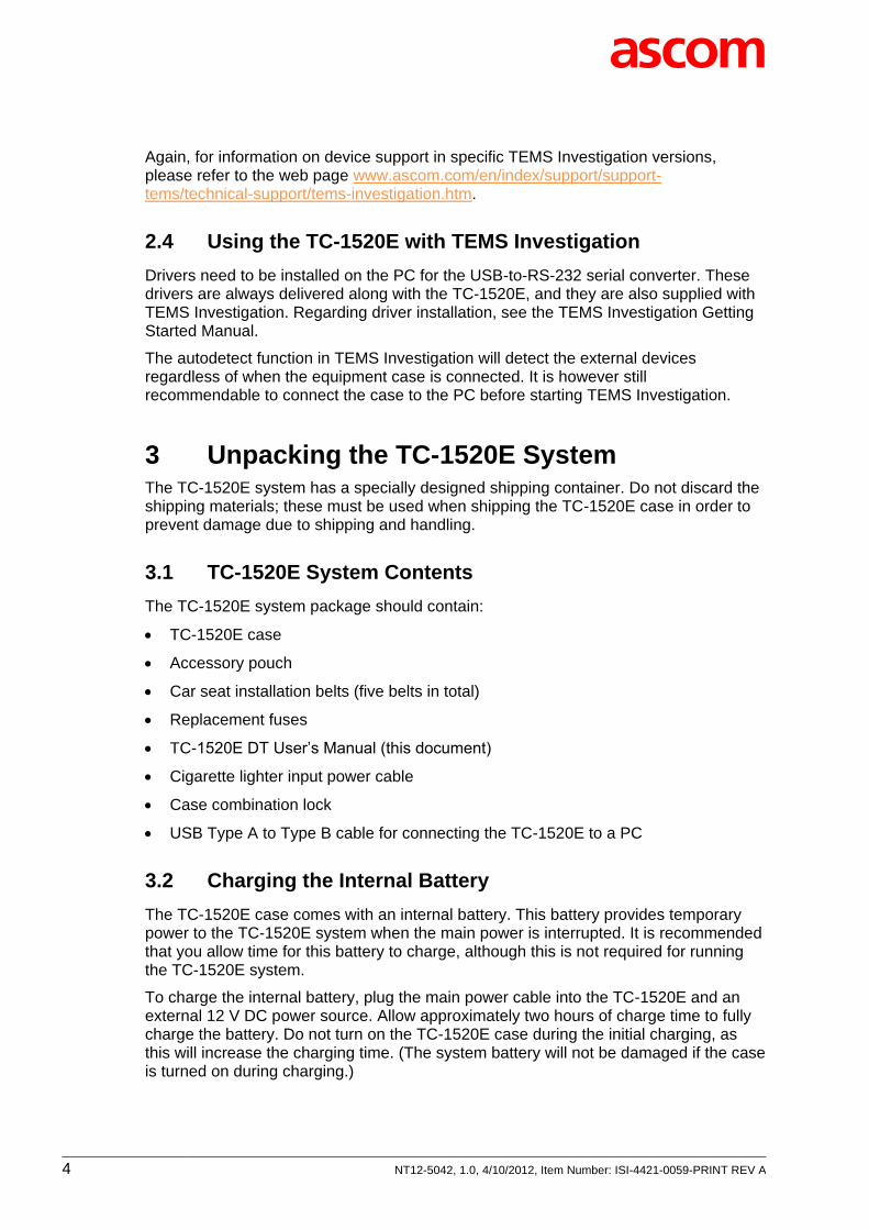
1. One pair of belts (short + long) is used to strap the case to the seat on each side. Perform steps 2–5 for each pair of belts.
2. Clasp the short belt with buckle receptacle to the front mounting hole of the case.
3. Clasp the long belt with buckle tongue to the rear mounting hole of the case.
4. Pass the long belt between the seat and the back rest, then wrap the belt around the seat from back to front.
5. Plug the buckle together and pull the belt tail firmly until the case sinks into the seat and does not move. You may need to apply pressure to the top of the closed case to assist in this tightening.
6. Next, open the lid and clasp the lid retainer belt to one of the lid’s locking holes.
7. Wrap the belt around the back rest and clasp the other end to the other locking hole in the lid.
8. Pull the belt tail firmly until the lid sinks into the back rest.
9. If the case has free movement, continue to tighten the belts until no free movement exists.
12 NT12-5042, 1.0, 4/10/2012, Item Number: ISI-4421-0059-PRINT REV A
TC-1520E case strapped to vehicle seat
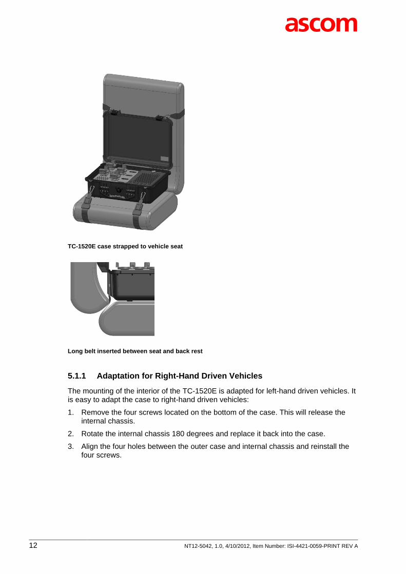
Long belt inserted between seat and back rest
5.1.1 Adaptation for Right-Hand Driven Vehicles
The mounting of the interior of the TC-1520E is adapted for left-hand driven vehicles. It is easy to adapt the case to right-hand driven vehicles:
1. Remove the four screws located on the bottom of the case. This will release the internal chassis.
2. Rotate the internal chassis 180 degrees and replace it back into the case.
3. Align the four holes between the outer case and internal chassis and reinstall the four screws.

NT12-5042, 1.0, 4/10/2012, Item Number: ISI-4421-0059-PRINT REV A 13
Detaching the internal chassis of the TC-1520E
5.2 System Power Cable
The power cable provided is specifically designed to handle the 15 A current required to operate the TC-1520E system. Only the supplied power cable should be used with the TC-1520E.
The cigarette lighter plug can be plugged into any automotive cigarette lighter receptacle with a minimum current capacity of 15 Amps.
The 3-pin right angle XLR connector plugs into the power receptacle on the connector panel.
TC-1520E power cable
The cigarette lighter plug has an integrated LED indicator. If this LED is not lit, the fuse may be blown.
Recommended fuse: Fast-acting 3AG cartridge fuse, 32 V DC 15 A, Littelfuse, 0312015.HXP.
5.3 TC-1520E USB Interface
Connect to the TC-1520E hub using the USB cable provided. Plug the Type B connector into the hub and the Type A connector into your PC.

14 NT12-5042, 1.0, 4/10/2012, Item Number: ISI-4421-0059-PRINT REV A
6 Shipping the TC-1520E System The internal components of the TC-1520E cannot withstand the shock and vibration forces that typically arise during commercial shipping. Therefore the TC-1520E may be commercially shipped only in its original shipping container.
Preparations for shipping:
1. Drain the UPS battery as described in Appendix A.
2. Pack the TC-1520E in its original shipping materials.
3. Do not pack any loose components inside the TC-1520E. This includes the phones, power cable, and accessory pouch. Pack these items separately in the shipping container. All fixed modules such as receivers and AQM modules may remain installed inside the TC-1520E case.
Failure to follow these instructions may damage the internal components of the TC-1520E case during shipment.
7 TC-1520E Specifications Operating temperature: 0°C ... 40°C
Storage temperature: –20°C ... 50°C
Weight or case with no scanners or AQM modules installed: 4.2 kg (9.3 lbs)
Input voltage: 9 ... 18 V DC (12 V DC nominal 15 A)
Auxiliary power receptacle: 12 V DC nominal 10 A
UPS controlled internal power: 12 V DC at 7.5 A
Internal USB hub: 7 ports supporting USB 1.1 or 2.0, 5 V DC at 0.5 A per port.
Up to 8 phone cradles supported
Case dimensions: See the drawing below.
Physical dimensions of TC-1520E (all measurements in mm)
500
400
190

NT12-5042, 1.0, 4/10/2012, Item Number: ISI-4421-0059-PRINT REV A 15
8 Regulatory Qualifications RoHS compliant
Appendix A. Procedure for Discharging the UPS Battery 1. Do not connect the TC-1520E power cable.
2. Power on the TC-1520E. The UPS unit will consume power over time. When the battery is completely drained, the green LED on top of the power distribution module will go out. It will take approximately 14 hours for a fully charged battery to drain.
To speed up the process, leave all internal devices connected. The external auxiliary cigarette lighter plug will not affect the battery discharge time.
![Index []INDEX Item Section Page Bridge Storing Material and Equipment On/Against Structures Restriction..... TC-6.14 115 Bridge Underclearance ..... TC-6.12 113](https://img.pdfslide.us/doc/110x75/5e32d981936425078231de8a/index-index-item-section-page-bridge-storing-material-and-equipment-onagainst.jpg)