Embed Size (px)
Citation preview
TC 1-240
1 SEPTEMBER 2004
SUPERSEDES TC 1-216, 8 October 1992
HEADQUARTERS, DEPARTMENT OF THE ARMY
DISTRIBUTION RESTRICTION: Approved for public release; distribution is unlimited
AIRCREW TRAINING MANUAL
CARGO HELICOPTER, CH-47

TC 1-240
TRAINING CIRCULAR HEADQUARTERS
NO. 1-240 DEPARTMENT OF THE ARMYWashington, DC, March 2003
AIRCREW TRAINING MANUALCH-47 CARGO HELICOPTER
CONTENTS
PAGE
PREFACE vi
CHAPTER 1. INTRODUCTION 1-1
1-1. Crew station designation.........................................................................................................1-11-2. Symbol usage and word distinctions........................................................................................1-1
CHAPTER 2. TRAINING 2-1
2-1. Qualification Training ...........................................................................................................2-12-2. Refresher Training.................................................................................................................2-22-3. Mission Training....................................................................................................................2-62-4. Continuation Training............................................................................................................2-72-5. Task Lists..............................................................................................................................2-82-6. Currency Requirements......................................................................................................2-12 2-7. NBC Training.....................................................................................................................2-12
CHAPTER 3. EVALUATIONS 3-1
3-1. Evaluation Principles...............................................................................................................3-13-2. Grading Considerations...........................................................................................................3-23-3. Crewmember Evaluation.........................................................................................................3-23-4. Evaluation Sequence...............................................................................................................3-43-5. Additional Evaluations............................................................................................................3-8
DISTRIBUTION RESTRICTION: Approved for public release; distribution is unlimited.
This publication supercedes TC 1-216 dated 8 October 1992.
i
TC 1-240
CHAPTER 4. CREW MEMBER TASKS 4-1
4-1. Task Contents.........................................................................................................................4-14-2. Tasks......................................................................................................................................4-7Task 1000 Participate in a crew mission briefing.....................................................................4-8 Task 1004 Plan a VFR flight...................................................................................................4-11Task 1006 Plan an IFR flight...................................................................................................4-13Task 1010 Prepare a performance planning card.....................................................................4-15Task 1012 Verify aircraft weight and balance.........................................................................4-27Task 1014 Operate ALSE........................................................................................................4-28Task 1016 Perform internal load operations............................................................................4-29Task 1022 Perform preflight inspection..................................................................................4-31Task 1024 Perform before-starting engine through before-leaving helicopter checks............4-32Task 1026 Maintain airspace surveillance...............................................................................4-35Task 1027 Perform health indicator test (HIT) / power assurance test (PAT).......................4-36Task 1028 Perform hover power check...................................................................................4-38Task 1032 Perform radio communication procedures.............................................................4-40Task 1034 Perform ground taxi...............................................................................................4-42Task 1038 Perform hovering flight..........................................................................................4-45Task 1040 Perform VMC takeoff............................................................................................4-48Task 1042 Perform cruise check procedures...........................................................................4-51Task 1044 Navigate by pilotage and dead reckoning..............................................................4-55Task 1046 Perform electronically aided navigation................................................................4-56Task 1052 Perform VMC flight maneuvers............................................................................4-57Task 1058 Perform VMC approach.........................................................................................4-60Task 1062 Perform slope operations.......................................................................................4-64Task 1063 Perform external load operations...........................................................................4-66Task 1064 Perform a roll-on landing.......................................................................................4-72Task 1070 Perform emergency procedures.............................................................................4-74Task 1094 Perform flight with AFCS OFF.............................................................................4-76Task 1170 Perform instrument takeoff....................................................................................4-77Task 1172 Perform radio navigation.......................................................................................4-79Task 1174 Perform holding procedures...................................................................................4-80Task 1176 Perform non-precision approach............................................................................4-81Task 1178 Perform precision approach...................................................................................4-83Task 1182 Perform unusual attitude recovery.........................................................................4-84Task 1184 Respond to inadvertent IMC..................................................................................4-85Task 1188 Operate aircraft survivability equipment...............................................................4-87Task 1190 Perform / identify hand and hand and arm signals................................................4-88Task 1194 Perform refueling operations (NCM).....................................................................4-89Task 1200 Perform NCM duties during maintenance test flight.............................................4-91Task 1202 Perform auxiliary power unit operations (APU)....................................................4-93Task 1262 Participate in a crew-level after-action review......................................................4-95Task 1413 Perform actions on contact....................................................................................4-97Task 1474 Respond to NVG failure......................................................................................4-100Task 2010 Perform multi-aircraft operations.........................................................................4-101Task 2012 Perform tactical flight mission planning..............................................................4-103
ii

TC 1-240
Task 2014 Perform ECM/ECCM procedures........................................................................4-105Task 2022 Transmit tactical reports.......................................................................................4-107Task 2024 Perform terrain flight navigation..........................................................................4-108Task 2026 Perform terrain flight...........................................................................................4-110Task 2034 Perform masking and unmasking.........................................................................4-112Task 2036 Perform terrain flight deceleration.......................................................................4-114Task 2050 Develop an emergency GPS recovery procedure................................................4-115Task 2052 Perform emergency GPS approach......................................................................4-122Task 2053 Perform water-bucket operations.........................................................................4-124Task 2054 Perform fast-rope insertion and extraction (FRIES)............................................4-129Task 2056 Perform rappelling operations.............................................................................4-132Task 2058 Perform special patrol infiltration/exfiltration (SPIES)......................................4-135 Task 2059 Perform rescue-hoist/winch operations...............................................................4-138Task 2064 Perform paradrop operations...............................................................................4-141Task 2066 Perform extended range fuel system procedures.................................................4-143Task 2068 Perform shipboard operations..............................................................................4-145Task 2074 Perform FARP operations....................................................................................4-148Task 2076 Perform Jacobs/Caving ladder operations...........................................................4-151Task 2078 Perform helocast/softduck operations..................................................................4-153Task 2079 Perform amphibious operations...........................................................................4-156Task 2086 Operate NVG with the AN/AVS-7 (ANVIS-HUD) attached..............................4-159Task 2112 Operate armament subsystem..............................................................................4-160Task 2125 Perform mountain/pinnacle and ridgeline operations..........................................4-162
CHAPTER 5. MAINTENANCE TEST PILOT TASKS 5-1
5-1. Task contents.........................................................................................................................5-15-2. Tasks......................................................................................................................................5-4Task 4000 Perform prior to maintenance test flight checks......................................................5-5Task 4001 Perform MTF before starting engine checks............................................................5-6Task 4002 Perform MTF starting engine checks.......................................................................5-7Task 4003 Perform MTF engine run-up checks........................................................................5-9Task 4004 Perform MTF taxi checks......................................................................................5-10Task 4005 Perform MTF before hover checks........................................................................5-11Task 4006 Perform MTF hover checks...................................................................................5-12Task 4007 Perform MTF in-flight checks...............................................................................5-13Task 4008 Perform autorotation RPM check..........................................................................5-14Task 4009 Perform turbine analysis check (TEAC) 712.........................................................5-15Task 4010 Perform power assurance check (PAC) 714..........................................................5-16Task 4011 Perform communication and navigation equipment checks..................................5-17Task 4012 Perform after-landing through engine shutdown checks.......................................5-18Task 4013 Perform special equipment or detailed procedures checks....................................5-19
iii
TC 1-240
CHAPTER 6. CREW COORDINATION 6-1
6-1. Crew coordination background................................................................................................6-16-2. Crew coordination elements....................................................................................................6-16-3. Crew coordination basic qualities............................................................................................6-26-4. Crew coordination objectives..................................................................................................6-66-5. Standard crew terminology......................................................................................................6-6
APPENDIX A. NONRATED CREW MEMBER TRAINING.............................................A-1
SECTION-I NCM TRAINING................................................................................................A-1
A-1. NCM aircraft qualification training.......................................................................................A-1A-2. NVG qualification training ..................................................................................................A-3A-3. Refresher training ................................................................................................................A-3A-4. Mission Training..................................................................................................................A-3A-5. Continuation training requirements.......................................................................................A-3A-6. NBC Training......................................................................................................................A-3
SECTION-II STANDARDIZATION INSTRUCTOR (SI),NON RATED CREWMEMBER INSTRUCTOR (FI), AND FLIGHT ENGINEER TRAINER (FET) TRAINING..................A-4
A-7. Qualification training............................................................................................................A-4
APPENDIX B. HEADS UP DISPLAY (HUD) B-1
B-1. General.................................................................................................................................B-1B-2. Qualification training............................................................................................................B-1B-3. Academic Training...............................................................................................................B-1B-4. Flight Training......................................................................................................................B-1B-5. Training documentation........................................................................................................B-2
APPENDIX C. T-55-L-712/714 QUALIFICATION TRAINING C-1
SECTION I 712 QUALIFICATION C-1C-1. General.................................................................................................................................C-1C-2. Prerequisites.........................................................................................................................C-1C-3. Academic Training...............................................................................................................C-1C-4. Flight Training......................................................................................................................C-2C-5. Evaluations...........................................................................................................................C-3
SECTION II 714 QUALIFICATION C-4C-6. General.................................................................................................................................C-4C-7. Prerequisites.........................................................................................................................C-4C-8. Academic Training...............................................................................................................C-4C-9. Flight Training......................................................................................................................C-5C-10. Evaluations.........................................................................................................................C-6
iv
TC 1-240
APPENDIX D. INSTRUCTOR PILOT SUPPLEMENTAL INFORMATION D-1
D-1. Emergency procedures training.............................................................................................D-1D-2. Instructor pilot techniques.....................................................................................................D-2
GLOSSARY.............................................................................................................GLOSSARY- 1REFERENCES....................................................................................................REFERENCES - 1INDEX...............................................................................................................................................BLANK FORMS
DA Form 4887-47 (Performance Planning Card)
v
TC 1-240
PREFACE
The ATM standardizes aircrew training programs and flight evaluation procedures. This manual provides specific guidelines for executing CH-47 aircrew training. It is based on the battle-focused training principles outlined in FM 7-1. It establishes crew member qualification, refresher, mission, and continuation training and evaluation requirements. This manual applies to all CH-47 crew members and their commanders.
This is not a stand-alone document. All of the requirements contained in Army regulations and TC 1-210, Commander’s Guide to the Aircrew Training Program, must be met. If differences exist between the maneuver descriptions in TM 1-1520-240-10 and this manual, this manual is the governing authority for training and flight evaluation purposes only. TM 1-1520-240-10 is the authority for operation of the aircraft. Implementation of this manual conforms to AR 95-1 and TC 1-210, commander’s guide. If a conflict exists between this manual and TC 1-210 (ATP Commander’s Guide) the commander determines the method of accomplishment based upon the requirement and the unit’s mission which manual takes precedence.
This manual (in conjunction with the AR’s and TC 1-210) will help aviation commanders, at all levels, develop a comprehensive aircrew training program. By using the ATM, commanders ensure that individual crew member and aircrew proficiency is commensurate with their units' mission and that aircrews routinely employ standard techniques and procedures.
Crew members will use this manual as a "how to" source for performing crew member duties. It provides performance standards and evaluation guidelines so that crew members know the level of performance expected. Each task has a description that describes how it may be performed to meet the standard.
Standardization officers, evaluators, and unit trainers will use this manual and TC 1-210, commander’s guide, as the primary tools to assist the commander in developing and implementing his aircrew training program.
The proponent of this publication is HQ TRADOC. Send comments and recommendations on DA Form 2028 through the aviation unit commander to Commander, US Army Aviation Center, ATTN: ATZQ-ES (Cargo Section), Building 4503 Kingsman Avenue, Fort Rucker, AL 36362-5263, DSN 558-3354/1564. Recommended changes may also be e-mailed to [email protected].
This publication implements portions of STANAG 3114 (Edition Six)/Air Standard 60/16, Aeromedical Training of Flight Personnel.
Unless this publication states otherwise, masculine nouns and pronouns do not refer exclusively to men.
This publication has been reviewed for operations security considerations.
vi
TC 1-240
CHAPTER 1
INTRODUCTION
This ATM describes training requirements for crew members. It will be used with AR 95-1, AR 600-105, AR 600-106, NGR (AR) 95-210, TC 1-210 and other applicable publications. The tasks in this ATM enhance training in individual and aircrew proficiency. The training focuses on the accomplishment of tasks supporting the unit's mission. The scope and level of training to be achieved individually by crew members and collectively by aircrews will be dictated by the METL. Commanders must ensure that aircrews are proficient in mission-essential tasks.
1-1 CREW STATION DESIGNATION. The commander will designate a crew station(s) for each crew member. The individual’s Commander’s Task List (CTL) must clearly indicate all crew station designations. Training and proficiency sustainment for rated crew members is required in each designated crew station with access to the flight controls. Standardization Instructor Pilots (SPs), Instructor Pilots (IPs), Instrument Examiners (IEs), and aviators designated to fly from both pilots’ seats will be evaluated in each seat during Annual Proficiency and Readiness Test (APART) evaluations. Maintenance Examiners (MEs), and Maintenance Pilots (MPs), will follow chapter 5 for crew station requirements and evaluations. This does not mean that all tasks must be evaluated in each seat. Sustainment training for Nonrated Crew Members (NCM) is required in each designated crew station. NCMs are required to be evaluated from all designated crew stations during the APART, but are not required to be evaluated in all tasks from each station.
1-2 SYMBOL USAGE AND WORD DISTINCTIONS
a. Symbol Usage. The diagonal (/) is used to indicate “or” or, “and”. For example, IP/SP may mean IP or SP or may mean IP and SP. For NCMs SI/FI may mean SI or FI or may mean SI and FI.
b. Word Distinctions.
(1) Warnings, cautions, and notes. These words emphasize important and critical instructions.
(a) A warning indicates an operating procedure or a practice which, if not correctly followed, could result in personal injury or loss of life.
(b) A caution indicates an operating procedure or a practice which, if not strictly observed, could result in damage to or destruction of equipment.
(c) A note indicates an operating procedure or condition, which is essential to highlight.
(2) Will, must, should and may. These words distinguish between mandatory, preferred, and acceptable methods of accomplishment.
(a) Will or must indicates a mandatory requirement.
1- 1

TC 1-240
(b) Should indicates a preferred, but non-mandatory, method of accomplishment.
(c) May indicates an acceptable method of accomplishment.
(3) Night Vision Devices
(a) NVS refers to the night vision system that is attached to the aircraft and is an integral component of the aircraft.
(b) NVG refers to any night vision goggle image intensifier system, for example, the AN/AVS-6 (ANVIS).
NOTE: NVD refers to both NVG and NVS.
c. Rated crew member (RCM). RCMs are aviators. Therefore, the terms "rated crew member," "aviator," and "pilot" are used synonymously.
(1) Pilot (PI). The PI will complete all assigned tasks by the PC.
(2) Pilot-in-Command (PC). The PC is overall responsible for the operation of the aircraft from pre-mission planning to mission complete and will assigned duties as necessary to the crew.
(3) Unit Trainer (UT). The UT is a specialized trainer appointed by the comman-der to assist in unit training.
(4) Instructor Pilot (IP). The IP trains and evaluates RCM and NCM as directed by the commander. The IP may evaluate an IP/SP during Proficiency Flight Evaluation (PFE) resulting from a lapse in aircraft or NVD currency.
(5) Instrument Examiner (IE). The IE will train and evaluate instrument tasks as directed by AR 95-1 and any local requirements.
(6) Standardization Instructor Pilot (SP). The SP trains and evaluates RCM and NCM; additionally he is responsible for the supervision and maintenance of the standardization program.
(7) Maintenance Test Pilot (MP). Conducts maintenance test flight procedures IAW chapter 5 of this ATM.
(8) Maintenance Test Pilot Evaluator (ME). Trains and evaluates MPs and MEs IAW chapter 5 of this ATM.
d. Nonrated crew member (NCM). NCMs are individuals other than aviators who per-form duties aboard an aircraft that are essential to the operation of the aircraft.
(1) Crew chief (CE). The CE assists the FE in maintaining his assigned aircraft and performs NCM duties.
(2) Flight Engineer (FE). The FE is responsible for maintaining his assigned aircraft and performing NCM duties. He is the supervisor and primary trainer for the crew chief and mechanics assigned to that aircraft. The commander selects NCMs to perform FE duties based on proficiency and experience.
1- 2
TC 1-240
(3) Nonrated Crew member Trainer (NCT). The Nonrated crew member trainer trains RL2 nonrated crew members in mission/additional tasks per the ATM and unit METL. To be qualified as an NCT, the crew member must demonstrate a higher level of knowledge and the ability to impart that knowl-edge toward training other nonrated crew members IAW the Instructor Pilots Handbook and Flight Engineer Instructor Course – Flight Training Guide.
(4) Nonrated crew member Flight Engineer Instructor (FI). The Nonrated crew member instructor (FI) trains and evaluates nonrated crew members in aircraft tasks per the ATM and unit METL. To be qualified as an FI the crew member must meet the requirements of AR 95-1.
(5) Nonrated crew member Standardization Instructor (SI). The SI trains and evaluates nonrated crew members, FIs and other SIs. He assists the unit SP with the supervision and maintenance of the standardization program. To be qualified as a SI the crew member must meet the requirements of AR 95-1.
NOTE 1: Unless otherwise specified, the abbreviation CE in the task descriptions refers to either the crew chief or the flight engineer.
e. Non-crew member. These individuals perform duties directly related to the in-flight mission of the aircraft but are not essential to the operation of the aircraft. AR 600-106 lists the categories for non-crew member positions and the number authorized in each unit. Non-crew members may perform CE/FE/NCT/FI/SI duties while on non-crew member flight status if they are MOS qualified and fully integrated into the commander’s ATP. Additionally, they are trained and designated to perform those duties for NCMs who are unable to fly.
1- 3
TC 1-240
Intentionally left blank.
1- 4
TC 1-240
CHAPTER 2
TRAINING
This chapter describes requirements for Qualification, Readiness Level (RL) progression, Mission, and Continuation training.
2-1 QUALIFICATION TRAINING. Crew member qualification requirements are IAW AR 95-1, TC 1-210, and this ATM. Crew members complete qualification training by demonstrating proficiency in all tasks required for the qualification to a SP, IP, ME, SI, or FI, as appropriate. Crew members undergoing qualification training in the aircraft must fly with a SP, IP, ME, SI, or FI as appropriate.
NOTE: Trainers who are evaluating/training NCMs must be at a station without access to the flight controls.
a. Aircraft Qualification.
(1) Rated Crew member. Initial qualification training in the CH-47 is conducted at the US Army Aviation Center, or at DA-approved training sites, in accordance with a USAAVNC-approved Program of Instruction.
(2) Nonrated Crew member. MOS qualification is conducted at DA-approved training sites. Aircraft Qualification Training for NCMs (15U) is conducted at the unit per this ATM (Appendix A), NCM ETP 2C-011-0002A, applicable regulations, and the commander’s ATP. The NCMs must complete academic and flight training and pass the required written examinations within 90 consecutive days (reserve components, 1 year). Qualification training requirements for SIs, FIs and NCTs are also outlined in Appendix A.
b. NVG Qualification. Initial NVG qualification and aircraft NVG qualification will be IAW TC 1-210 (chapter 4), the USAAVNC NVG training support package (TSP), and this ATM.
(1) Initial NVG Qualification. Initial qualification will be conducted at the U.S. Army Aviation Center or DA-approved training site, according to the USAAVNC approved Program Of Instruction, or locally using the USAAVNC NVG ETP. The USAAVNC NVG ETP may be obtained by writing to the Commander, US Army Aviation Center, ATTN: ATZQ-TDS-O, Fort Rucker, Alabama 36362-5000.
(2) Aircraft NVG Qualification.
(a) Academic training. The crew member will receive training and demonstrate a working knowledge of the topics of paragraph 3-4b. (10).
(b) Flight training. The crew member will receive training, and demonstrate proficiency, from the designated crew station, in all base tasks marked with an X in the NVG column of figure 2-3 or 2-4 as appropriate. The commander may select any additional base tasks at his discretion.
2-1
TC 1-240
(3) Minimum Flight Hours. There are no minimum flight hour requirements. The qualification is proficiency based determined by the crew member’s ability to satisfactorily accomplish the designated tasks.
c. Additional Qualifications
(1) Heads up Display – Appendix B.
(2) T55-L-712 / T55-GA-714 – Appendix C.
2-2 REFRESHER TRAINING: Crew members are designated RL3 when they meet the criteria of TC 1-210.
a. Aircraft Refresher Training.
(1) Academic training. The crew member will receive training and demonstrate a working knowledge of the topics listed in Paragraph 3-4b. (1)-(7) and complete an operator’s manual written examination.
(2) Flight training. The crew member will receive training from all designated crew station(s). A task that may be performed from either crew station need not be evaluated from both. Proficiency must be demonstrated in all modes marked with an “X” in the D, I, and N columns in figure 2-3 or 2-4 as applicable. Figure 2-1 and 2-2 are guides for developing the refresher flight training. Actual hours will be based on individual crew member proficiency. The evaluation may be continuous.
(3) Refresher training as a result of a training or evaluation deficiency. Academic and flight training required as a result of a training deficiency or an unsatisfactory evaluation will consist of the academic training, flight training, and evaluation required to regain proficiency. The evaluation will at a minimum consist of the deficient task(s) and any other tasks selected by the commander or the evaluator. There is no requirement to complete the entire refresher training program outlined in this ATM. The evaluation may be continuous.
b. NVG refresher training.
(1) Academic training. The crew member will receive training and demonstrate a working knowledge of the applicable topics in 3-4b. (10).
(2) Flight training. The crew member will receive training and demonstrate proficiency in all base tasks marked with an X in the NVG column of figure 2-3 or 2-4 as applicable. The commander may select any additional base tasks at his discretion.
(3) Minimum Flight Hours. There are no minimum flight hour requirements. The training is proficiency based determined by the crew member’s ability to satisfactorily accomplish the designated tasks.
2-2
TC 1-240
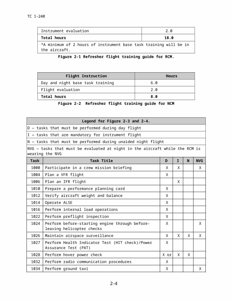
Flight Instruction HoursDay and night base task training 6.0
Flight evaluation 2.0*Instrument base task training (aircraft/simulator) 8.0
Instrument evaluation 2.0Total hours 18.0*A minimum of 2 hours of instrument base task training will be in the aircraft.
Figure 2-1 Refresher flight training guide for RCM.
Flight Instruction HoursDay and night base task training 6.0
Flight evaluation 2.0Total hours 8.0
Figure 2-2 Refresher flight training guide for NCM
Legend for Figure 2-3 and 2-4.D — tasks that must be performed during day flightI — tasks that are mandatory for instrument flight
N — tasks that must be performed during unaided night flight NVG — tasks that must be evaluated at night in the aircraft while the RCM is wearing the NVG
Task Task Title D I N NVG
1000 Participate in a crew mission briefing X X X
1004 Plan a VFR flight X
1006 Plan an IFR flight X
1010 Prepare a performance planning card X
1012 Verify aircraft weight and balance X
1014 Operate ALSE X
1016 Perform internal load operations X
1022 Perform preflight inspection X
1024 Perform before-starting engine through before- leaving helicopter checks X X
1026 Maintain airspace surveillance X X X X
1027 Perform Health Indicator Test (HIT check)/Power Assurance Test (PAT) X
1028 Perform hover power check X or X X
1032 Perform radio communication procedures X
1034 Perform ground taxi X X
1038 Perform hovering flight X X X
1040 Perform VMC takeoff X X X
1042 Perform cruise check procedures X X X
2-3
TC 1-240
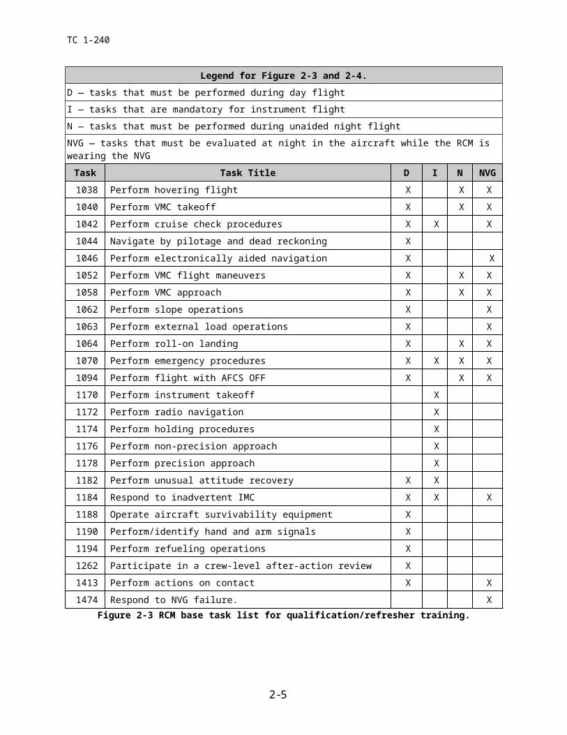
Legend for Figure 2-3 and 2-4.D — tasks that must be performed during day flight
I — tasks that are mandatory for instrument flightN — tasks that must be performed during unaided night flight
NVG — tasks that must be evaluated at night in the aircraft while the RCM is wearing the NVG
Task Task Title D I N NVG
1044 Navigate by pilotage and dead reckoning X
1046 Perform electronically aided navigation X X
1052 Perform VMC flight maneuvers X X X
1058 Perform VMC approach X X X
1062 Perform slope operations X X
1063 Perform external load operations X X
1064 Perform roll-on landing X X X
1070 Perform emergency procedures X X X X
1094 Perform flight with AFCS OFF X X X
1170 Perform instrument takeoff X
1172 Perform radio navigation X
1174 Perform holding procedures X
1176 Perform non-precision approach X
1178 Perform precision approach X
1182 Perform unusual attitude recovery X X
1184 Respond to inadvertent IMC X X X
1188 Operate aircraft survivability equipment X
1190 Perform/identify hand and arm signals X
1194 Perform refueling operations X
1262 Participate in a crew-level after-action review X
1413 Perform actions on contact X X
1474 Respond to NVG failure. XFigure 2-3 RCM base task list for qualification/refresher training.
2-4

TC 1-240
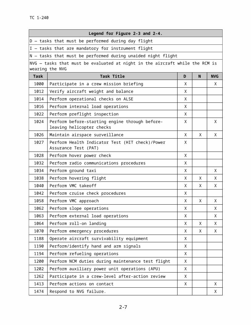
Legend for Figure 2-3 and 2-4.D — tasks that must be performed during day flight
I — tasks that are mandatory for instrument flightN — tasks that must be performed during unaided night flight
NVG — tasks that must be evaluated at night in the aircraft while the RCM is wearing the NVGTask Task Title D N NVG
1000 Participate in a crew mission briefing X X
1012 Verify aircraft weight and balance X
1014 Perform operational checks on ALSE X
1016 Perform internal load operations X
1022 Perform preflight inspection X
1024 Perform before-starting engine through before- leaving helicopter checks X X
1026 Maintain airspace surveillance X X X
1027 Perform Health Indicator Test (HIT check)/Power Assurance Test (PAT) X
1028 Perform hover power check X
1032 Perform radio communications procedures X
1034 Perform ground taxi X X
1038 Perform hovering flight X X X
1040 Perform VMC takeoff X X X
1042 Perform cruise check procedures X
1058 Perform VMC approach X X X
1062 Perform slope operations X X
1063 Perform external load operations X X
1064 Perform roll-on landing X X X
1070 Perform emergency procedures X X X
1188 Operate aircraft survivability equipment X
1190 Perform/identify hand and arm signals X
1194 Perform refueling operations X
1200 Perform NCM duties during maintenance test flight X
1202 Perform auxiliary power unit operations (APU) X
1262 Participate in a crew-level after-action review X
1413 Perform actions on contact X X
1474 Respond to NVG failure. XFigure 2-4 NCM (15U) base task list for qualification/refresher training.
2-5
TC 1-240
2-3 MISSION TRAINING. Crew members are designated RL2 when they meet the criteria of TC 1-210.
a. Training Requirements.
(1) Academic. The crew member will receive training and demonstrate a working knowledge of the topics listed in Paragraph 3-4b.(8)&(9).
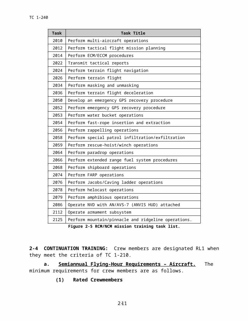
(2) Flight training. The training will consist of those mission tasks in figure 2-5 as selected by the commander and any additional tasks necessary to complete the unit’s mission. This training may be conducted by a UT/NCT. The crew member will receive training from all designated crew station(s). A task that may be performed from either crew station need not be evaluated from both. Flight mission-training hour requirements are based on demonstrated proficiency. The evaluation must be conducted by an SP, IP, SI, or FI and may be continuous.
b. NVG Mission Training. NVG mission training will be per the commander’s training program specifying tasks and flight hours. When commanders determine a requirement for using NVG in mission profiles, they must develop a mission training program, specify mission tasks, and determine the minimum number of NVG training hours required. Before undergoing NVG mission training, the aviator must be NVG RL2 in the CH-47D.
(1) Academic training. The crew member will receive training and demonstrate a working knowledge of the subject areas in paragraph 3-4b and any additional subject areas selected by the commander.
(2) Flight training. The crew member will receive flight training and demonstrate proficiency in the mission and additional NVG tasks as specified on the task list for the crew member’s position.
(3) Minimum flight hours. There are no minimum flight hour requirements. The training is proficiency based determined by the crew member’s ability to satisfactorily accomplish the designated tasks. NVG mission training may be included as part of refresher training.
(4) HUD Qualification. It is recommended that HUD qualification be completed during mission training.
c. MP and ME mission training. MPs and MEs should be limited to duties in one primary and one alternate or additional aircraft. The MP/ME will complete tasks outlined in figure 2-8 and should be required to complete those mission/additional tasks selected by the commander. Crew members undergoing training in the aircraft must fly with an ME for maintenance training.
(1) Academic training. The MP will receive training and demonstrate a working knowledge of the topics listed in paragraph 3-4b.(11).
(2) Flight training. The MP/ME will receive flight training and demonstrate proficiency in all tasks in figure 2-8. See chapter 5 for more guidance.
2-6
TC 1-240
Task Task Title2010 Perform multi-aircraft operations
2012 Perform tactical flight mission planning
2014 Perform ECM/ECCM procedures
2022 Transmit tactical reports
2024 Perform terrain flight navigation
2026 Perform terrain flight
2034 Perform masking and unmasking
2036 Perform terrain flight deceleration
2050 Develop an emergency GPS recovery procedure
2052 Perform emergency GPS recovery procedure
2053 Perform water bucket operations
2054 Perform fast-rope insertion and extraction
2056 Perform rappelling operations
2058 Perform special patrol infiltration/exfiltration
2059 Perform rescue-hoist/winch operations
2064 Perform paradrop operations
2066 Perform extended range fuel system procedures
2068 Perform shipboard operations
2074 Perform FARP operations
2076 Perform Jacobs/Caving ladder operations
2078 Perform helocast operations
2079 Perform amphibious operations
2086 Operate NVD with AN/AVS-7 (ANVIS HUD) attached
2112 Operate armament subsystem
2125 Perform mountain/pinnacle and ridgeline operations.Figure 2-5 RCM/NCM mission training task list.
2-4 CONTINUATION TRAINING: Crew members are designated RL1 when they meet the criteria of TC 1-210.
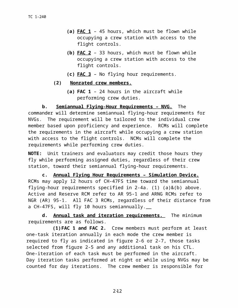
a. Semiannual Flying-Hour Requirements – Aircraft. The minimum requirements for crew members are as follows.
(1) Rated Crewmembers
(a) FAC 1 – 45 hours, which must be flown while occupying a crew station with access to the flight controls.
(b) FAC 2 – 33 hours, which must be flown while occupying a crew station with access to the flight controls.
(c) FAC 3 – No flying hour requirements.
2-7
TC 1-240
(2) Nonrated crew members.
(a) FAC 1 – 24 hours in the aircraft while performing crew duties.
b. Semiannual Flying-Hour Requirements – NVG. The commander will determine semiannual flying-hour requirements for NVGs. The requirement will be tailored to the individual crew member based upon proficiency and experience. RCMs will complete the requirements in the aircraft while occupying a crew station with access to the flight controls. NCMs will complete the requirements while performing crew duties.
NOTE: Unit trainers and evaluators may credit those hours they fly while performing assigned duties, regardless of their crew station, toward their semiannual flying-hour requirements.
c. Annual Flying Hour Requirements – Simulation Device. RCMs may apply 12 hours of CH-47FS time toward the semiannual flying-hour requirements specified in 2-4a. (1) (a)&(b) above. Active and Reserve RCM refer to AR 95-1 and ARNG RCMs refer to NGR (AR) 95-1. All FAC 3 RCMs, regardless of their distance from a CH-47FS, will fly 10 hours semiannually.
d. Annual task and iteration requirements. The minimum requirements are as follows.
(1) FAC 1 and FAC 2. Crew members must perform at least one-task iteration annually in each mode the crew member is required to fly as indicated in figure 2-6 or 2-7, those tasks selected from figure 2-5 and any additional task on his CTL. One-iteration of each task must be performed in the aircraft. Day iteration tasks performed at night or while using NVGs may be counted for day iterations. The crew member is responsible for maintaining proficiency in each task. The commander may require additional iterations of specific tasks.
(2) FAC 3. Each crew member must perform, in the simulator, at least one-iteration annually of each task annotated on the CTL. The crew member is responsible for maintaining proficiency in each task. The commander may require additional iterations of specific tasks.
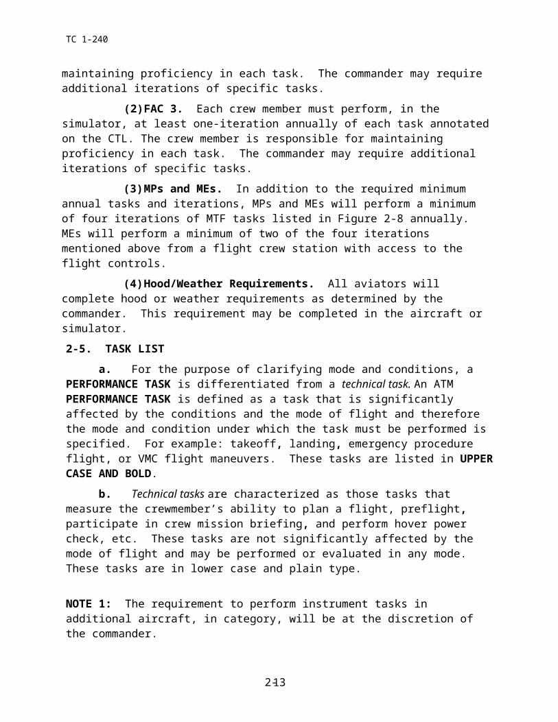
(3) MPs and MEs. In addition to the required minimum annual tasks and iterations, MPs and MEs will perform a minimum of four iterations of MTF tasks listed in Figure 2-8 annually. MEs will perform a minimum of two of the four iterations mentioned above from a flight crew station with access to the flight controls.
(4) Hood/Weather Requirements. All aviators will complete hood or weather requirements as determined by the commander. This requirement may be completed in the aircraft or simulator.
2-5. TASK LIST
a. For the purpose of clarifying mode and conditions, a PERFORMANCE TASK is differentiated from a technical task. An ATM PERFORMANCE TASK is defined as a task that is significantly affected by the conditions and the mode of flight and therefore the mode and condition under which the task must be performed is specified. For example: takeoff, landing, emergency procedure flight, or VMC flight maneuvers. These tasks are listed in UPPER CASE AND BOLD.
2-8
TC 1-240
b. Technical tasks are characterized as those tasks that measure the crewmember’s ability to plan a flight, preflight, participate in crew mission briefing, and perform hover power check, etc. These tasks are not significantly affected by the mode of flight and may be performed or evaluated in any mode. These tasks are in lower case and plain type.
NOTE 1: The requirement to perform instrument tasks in additional aircraft, in category, will be at the discretion of the commander.
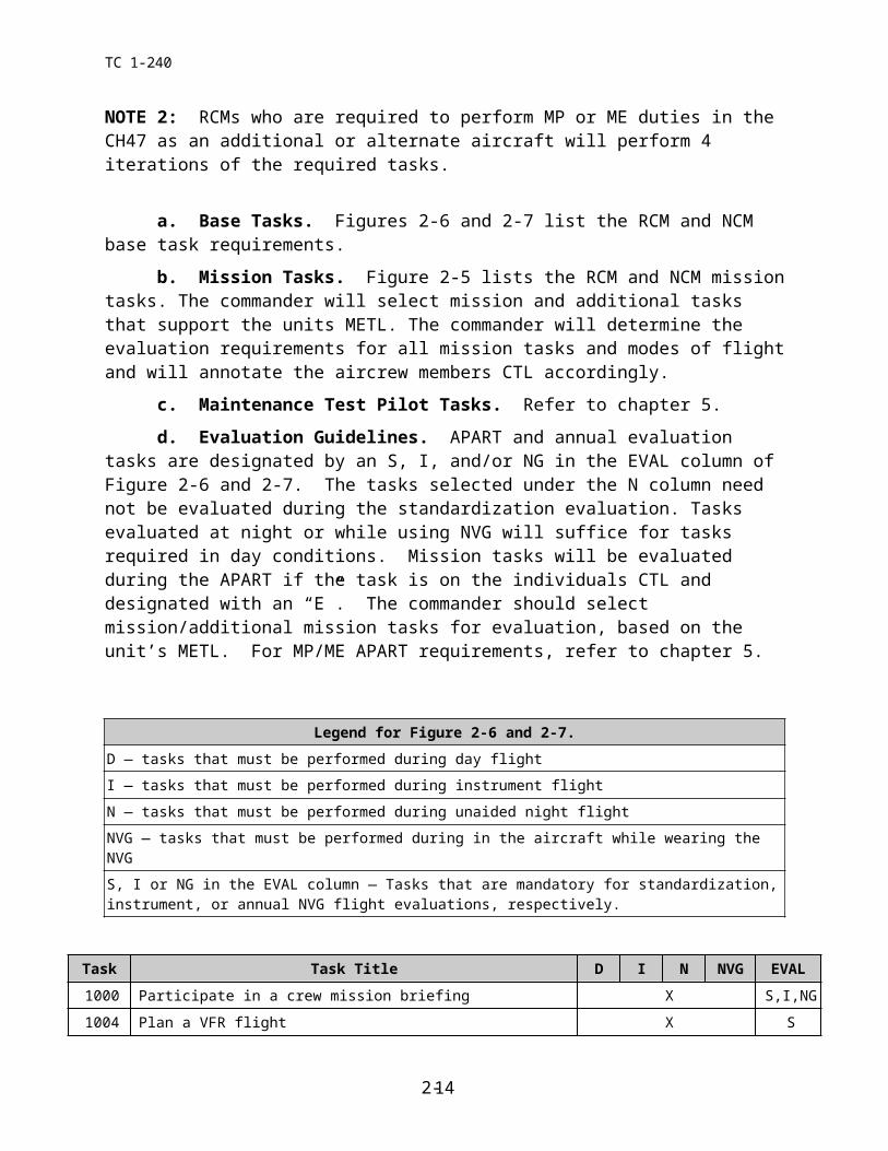
NOTE 2: RCMs who are required to perform MP or ME duties in the CH47 as an additional or alternate aircraft will perform 4 iterations of the required tasks.
a. Base Tasks. Figures 2-6 and 2-7 list the RCM and NCM base task requirements.
b. Mission Tasks. Figure 2-5 lists the RCM and NCM mission tasks. The commander will select mission and additional tasks that support the units METL. The commander will determine the evaluation requirements for all mission tasks and modes of flight and will annotate the aircrew members CTL accordingly.
c. Maintenance Test Pilot Tasks. Refer to chapter 5.
d. Evaluation Guidelines. APART and annual evaluation tasks are designated by an S, I, and/or NG in the EVAL column of Figure 2-6 and 2-7. The tasks selected under the N column need not be evaluated during the standardization evaluation. Tasks evaluated at night or while using NVG will suffice for tasks required in day conditions. Mission tasks will be evaluated during the APART if the task is on the individuals CTL and designated with an “E”. The commander should select mission/additional mission tasks for evaluation, based on the unit’s METL. For MP/ME APART requirements, refer to chapter 5.
Legend for Figure 2-6 and 2-7.D — tasks that must be performed during day flight
I — tasks that must be performed during instrument flightN — tasks that must be performed during unaided night flight
NVG — tasks that must be performed during in the aircraft while wearing the NVGS, I or NG in the EVAL column — Tasks that are mandatory for standardization, instrument, or annual NVG flight evaluations, respectively.
Task Task Title D I N NVG EVAL
1000 Participate in a crew mission briefing X S,I,NG
1004 Plan a VFR flight X S
1006 Plan an IFR flight X I
1010 Prepare a performance planning card X S
1012 Verify aircraft weight and balance X S
1014 Operate ALSE X S
2-9
TC 1-240
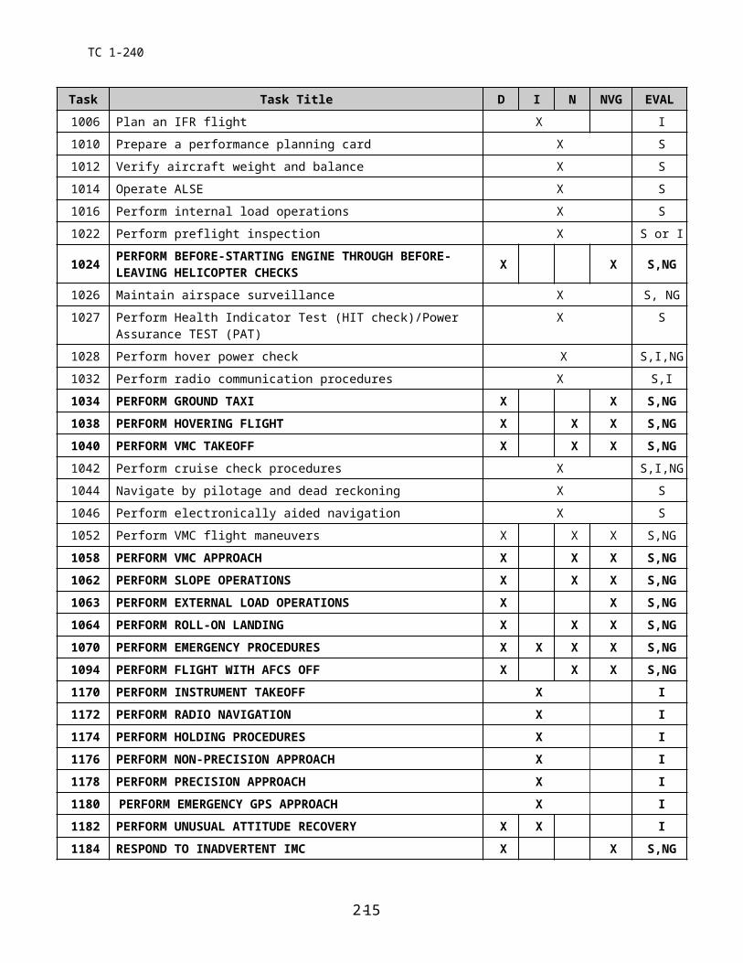
Task Task Title D I N NVG EVAL
1016 Perform internal load operations X S
1022 Perform preflight inspection X S or I
1024 PERFORM BEFORE-STARTING ENGINE THROUGH BEFORE- LEAVING HELICOPTER CHECKS X X S,NG
1026 Maintain airspace surveillance X S, NG
1027 Perform Health Indicator Test (HIT check)/Power Assurance TEST (PAT) X S
1028 Perform hover power check X S,I,NG
1032 Perform radio communication procedures X S,I
1034 PERFORM GROUND TAXI X X S,NG1038 PERFORM HOVERING FLIGHT X X X S,NG1040 PERFORM VMC TAKEOFF X X X S,NG1042 Perform cruise check procedures X S,I,NG
1044 Navigate by pilotage and dead reckoning X S
1046 Perform electronically aided navigation X S
1052 Perform VMC flight maneuvers X X X S,NG
1058 PERFORM VMC APPROACH X X X S,NG1062 PERFORM SLOPE OPERATIONS X X X S,NG1063 PERFORM EXTERNAL LOAD OPERATIONS X X S,NG1064 PERFORM ROLL-ON LANDING X X X S,NG1070 PERFORM EMERGENCY PROCEDURES X X X X S,NG1094 PERFORM FLIGHT WITH AFCS OFF X X X S,NG1170 PERFORM INSTRUMENT TAKEOFF X I1172 PERFORM RADIO NAVIGATION X I1174 PERFORM HOLDING PROCEDURES X I1176 PERFORM NON-PRECISION APPROACH X I1178 PERFORM PRECISION APPROACH X I1180 PERFORM EMERGENCY GPS APPROACH X I1182 PERFORM UNUSUAL ATTITUDE RECOVERY X X I1184 RESPOND TO INADVERTENT IMC X X S,NG1188 Operate aircraft survivability equipment X S
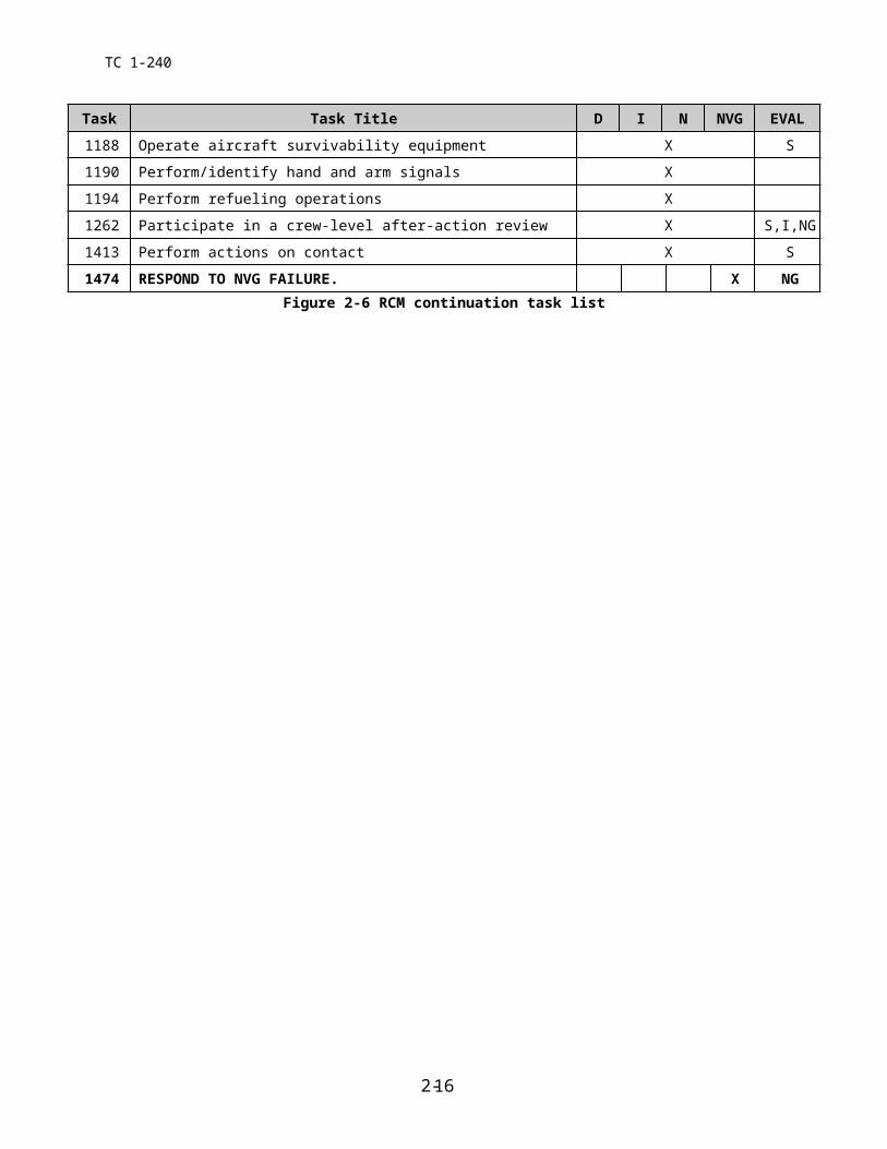
1190 Perform/identify hand and arm signals X
1194 Perform refueling operations X
1262 Participate in a crew-level after-action review X S,I,NG
1413 Perform actions on contact X S
1474 RESPOND TO NVG FAILURE. X NGFigure 2-6 RCM continuation task list
2-10

TC 1-240
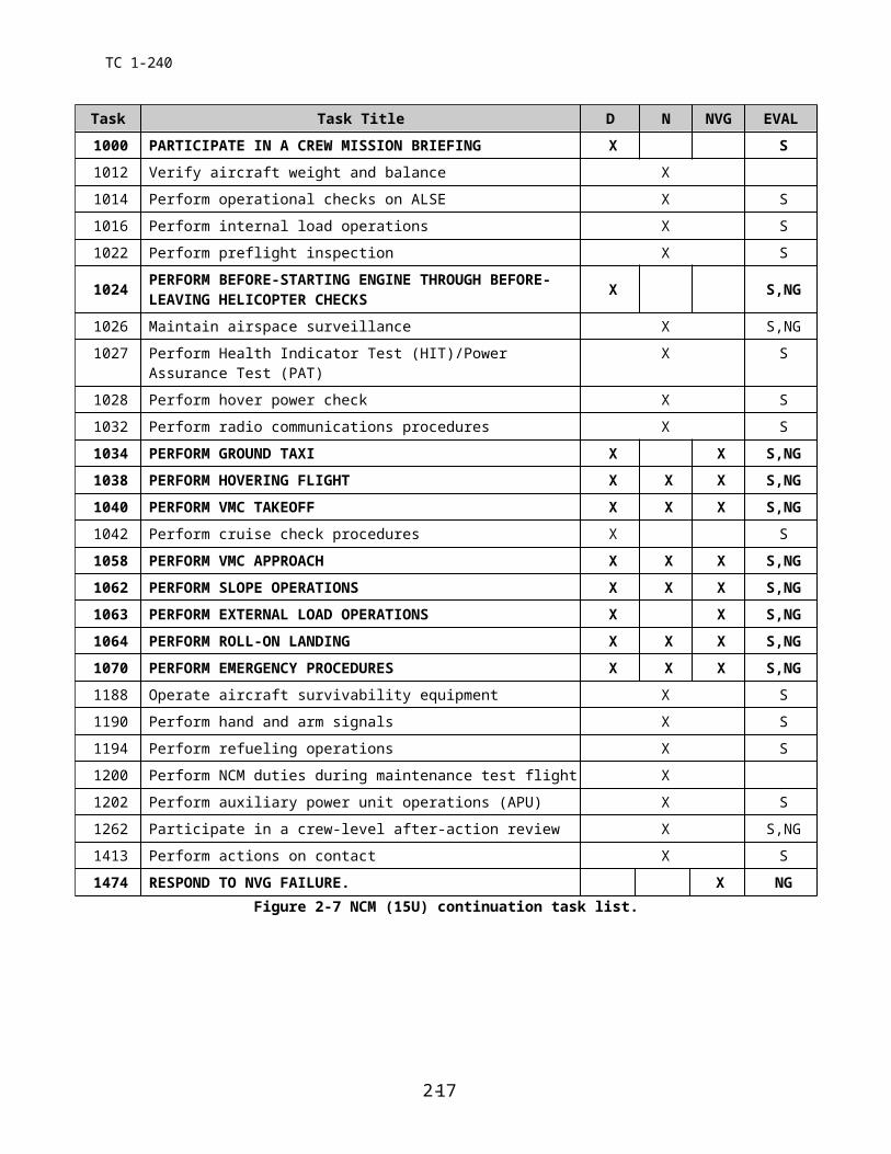
Task Task Title D N NVG EVAL
1000 PARTICIPATE IN A CREW MISSION BRIEFING X S1012 Verify aircraft weight and balance X
1014 Perform operational checks on ALSE X S
1016 Perform internal load operations X S
1022 Perform preflight inspection X S
1024 PERFORM BEFORE-STARTING ENGINE THROUGH BEFORE- LEAVING HELICOPTER CHECKS X S,NG
1026 Maintain airspace surveillance X S,NG
1027 Perform Health Indicator Test (HIT)/Power Assurance Test (PAT) X S
1028 Perform hover power check X S
1032 Perform radio communications procedures X S
1034 PERFORM GROUND TAXI X X S,NG1038 PERFORM HOVERING FLIGHT X X X S,NG1040 PERFORM VMC TAKEOFF X X X S,NG1042 Perform cruise check procedures X S
1058 PERFORM VMC APPROACH X X X S,NG1062 PERFORM SLOPE OPERATIONS X X X S,NG1063 PERFORM EXTERNAL LOAD OPERATIONS X X S,NG1064 PERFORM ROLL-ON LANDING X X X S,NG1070 PERFORM EMERGENCY PROCEDURES X X X S,NG1188 Operate aircraft survivability equipment X S
1190 Perform hand and arm signals X S
1194 Perform refueling operations X S
1200 Perform NCM duties during maintenance test flight X
1202 Perform auxiliary power unit operations (APU) X S
1262 Participate in a crew-level after-action review X S,NG
1413 Perform actions on contact X S
1474 RESPOND TO NVG FAILURE. X NGFigure 2-7 NCM (15U) continuation task list.
2-11
TC 1-240
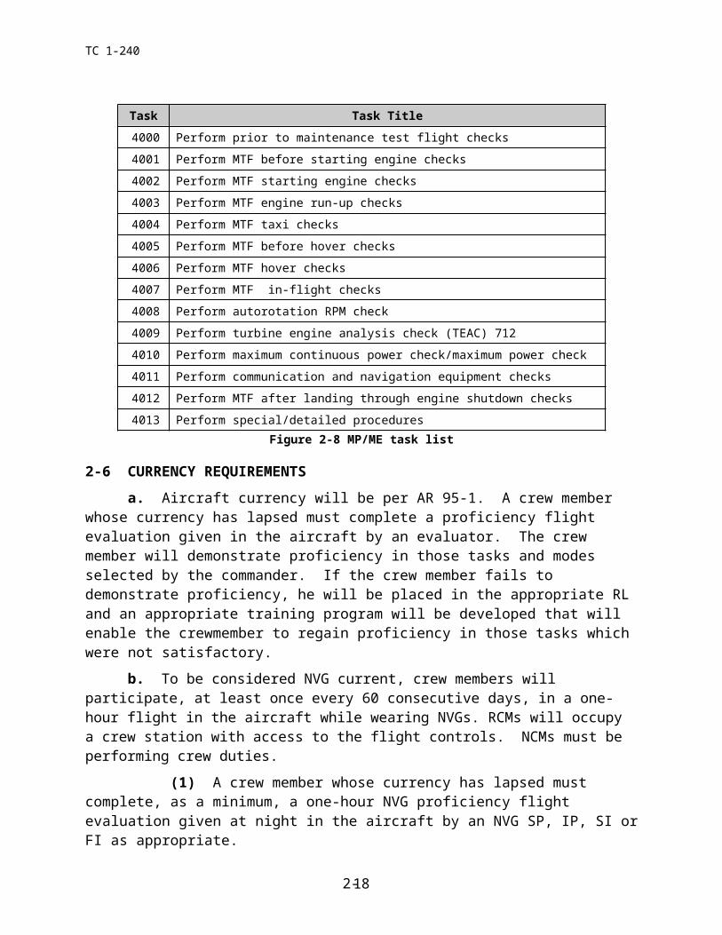
Task Task Title4000 Perform prior to maintenance test flight checks
4001 Perform MTF before starting engine checks
4002 Perform MTF starting engine checks
4003 Perform MTF engine run-up checks
4004 Perform MTF taxi checks
4005 Perform MTF before hover checks
4006 Perform MTF hover checks
4007 Perform MTF in-flight checks
4008 Perform autorotation RPM check
4009 Perform turbine engine analysis check (TEAC) 712
4010 Perform maximum continuous power check/maximum power check
4011 Perform communication and navigation equipment checks
4012 Perform MTF after landing through engine shutdown checks
4013 Perform special/detailed proceduresFigure 2-8 MP/ME task list
2-6 CURRENCY REQUIREMENTS
a. Aircraft currency will be per AR 95-1. A crew member whose currency has lapsed must complete a proficiency flight evaluation given in the aircraft by an evaluator. The crew member will demonstrate proficiency in those tasks and modes selected by the commander. If the crew member fails to demonstrate proficiency, he will be placed in the appropriate RL and an appropriate training program will be developed that will enable the crewmember to regain proficiency in those tasks which were not satisfactory.
b. To be considered NVG current, crew members will participate, at least once every 60 consecutive days, in a one-hour flight in the aircraft while wearing NVGs. RCMs will occupy a crew station with access to the flight controls. NCMs must be performing crew duties.
(1) A crew member whose currency has lapsed must complete, as a minimum, a one-hour NVG proficiency flight evaluation given at night in the aircraft by an NVG SP, IP, SI or FI as appropriate.
(2) The RCM must occupy a crew station with access to the flight controls during the evaluation.
(3) Minimum tasks to be evaluated are indicated by an X in the NVG column of Figure 2-3 or 2-4 as applicable. The commander may designate other mission and/or additional tasks.
2-7 NBC TRAINING. IAW TC 1-210. Crew members must wear the complete NBC ensemble during NBC training. All NBC training will be performed in the aircraft. NBC training is not required for FAC 3 positions.
a. RCMs will receive NBC training in the tasks listed below. The commander may select other tasks based on the unit mission.
2-12

TC 1-240
(1) Task 1022, Perform preflight inspection.
(2) Task 1024, Perform before-starting engine through before leaving helicopter checks.
(3) Task 1028, Perform hover power check.
(4) Task 1040, Perform VMC takeoff (terrain flight).
(5) Task 1058, Perform VMC approach (terrain flight)
(6) Task 2026, Perform terrain flight.
(7) Task 2036, Perform terrain flight deceleration.
b. NCMs will receive NBC training in the base tasks listed below. The commander may select other tasks based on the unit's mission.
(1) Task 1022, Perform preflight inspection.
(2) Task 1024, Perform before-starting engine through before leaving helicopter checks.
(3) Task 1042, Perform Cruise check Procedures.
2-13
TC 1-240
Intentionally left blank.
2-14
TC 1-240
CHAPTER 3
EVALUATIONS
This chapter describes evaluation principles and grading considerations. It also contains guidelines for conducting academic and hands-on performance testing. Evaluations are a primary means of assessing flight standardization and crew member proficiency. Evaluations will be conducted per AR 95-1, the Commander’s ATP in conjunction with TC 1-210, and this ATM.
1. EVALUATION PRINCIPLES. The value of any evaluation depends on adherence to fundamental evaluation principles.
a. These principles are described below.
(1) The evaluators must be selected not only for their technical qualifications but also for their demonstrated performance, objectivity, and ability to observe and to provide con-structive comments. These evaluators are the SPs, IPs, IEs, MEs, SIs, and FIs who assist the commander in administering the ATP.
(2) The method used to conduct the evaluation must be based on uniform and standard objectives. In addition, it must be consistent with the unit's mission and must strictly adhere to the appropriate SOPs and regulations. The evaluator must ensure a complete evaluation is given in all areas and refrain from making a personal “area of expertise” a dominant topic during the evaluation.
(3) All participants must completely understand the purpose of the evaluation.
(4) Cooperation by all participants is necessary to guarantee the accomplishment of the evaluation objectives. The emphasis is on all participants, not just on the examinee.
(5) The evaluation must produce specific findings to identify training needs. Any crew member affected by the evaluation needs to know what is being performed correctly and incorrectly and how improvements can be made.
b. An evaluation will determine the examinee's ability to perform essential hands-on/academic tasks to prescribed standards. Flight evaluations will also determine the examinee’s ability to exercise crew coordination in completing these tasks.
c. The guidelines for evaluating crew coordination are based on a subjective analysis of how effectively a crew performs together to accomplish a series of tasks. The evaluator must determine how effectively the examinee employs air crew coordination as outlined in Chapter 6.
d. In all phases of evaluation, the evaluator is expected to perform as an effective crew member. However, in order for the evaluator to determine the examinee’s level of proficiency, the evaluator may intentionally perform as an ineffective crew member. In such cases, a realistic, meaningful, and planned method should be developed to pass this task back to the examinee effectively. During the conduct of the flight evaluation, the evaluator will normally perform as outlined in the task description or as directed by the examinee. At some point, the evaluator may perform a role reversal with the examinee. The examinee must be made aware of both the initiation and termination of role reversals. The examinee must know when he is being supported by a fully functioning crew member.
3-1
TC 1-240
NOTE: When evaluating a SP, IP, IE, ME, UT, or PC, the evaluator must advise the examinee that, during role-reversal, he may deliberately perform some tasks or crew coordination outside the standards to check the examinee's diagnostic and corrective action skills.
3-1 GRADING CONSIDERATIONS.
a. Academic Evaluation. The examinee must demonstrate a working knowledge and understanding of the appropriate subject areas in paragraph 3-4 b.
b. Flight Evaluation.
(1) Academic. Some tasks are identified in TRAINING AND EVALUATION REQUIREMENTS as tasks which may be evaluated academically. The examinee must demonstrate a working knowledge of the tasks. Evaluators may use Computer Based Instruction (CBI), mock-ups, or other approved devices to assist in determining the examinee’s knowledge of the tasks.
(2) In the aircraft or in the simulator. Tasks which require evaluation under these conditions must be performed in the aircraft or the CH-47 simulator. Task standards are based on an ideal situation. Grading is based on meeting the minimum standards. If other than ideal conditions exist, i.e. high winds, turbulence, or poor visibility, the evaluator should consider those conditions while grading the maneuvers.
3-2 CREW MEMBER EVALUATION. Evaluations are conducted to determine the crew member’s ability to perform the tasks on his CTL and check the understanding of required academic subjects listed in this ATM. The evaluator will determine the amount of time devoted to each phase. When the examinee is an evaluator/trainer, the recommended procedure is for the evaluator to reverse roles with the examinee. When the evaluator uses this technique, the examinee must understand how the role-reversal will be conducted and when it will be in effect. Initial validation of a crew member’s qualifications following an Additional Skill Identifier (ASI) producing course of flight instruction/school, i.e. CH-47 Instructor Pilot course, Maintenance Test Pilot course, Instrument Examiner’s course, or Flight Engineer Instructor course, will be conducted in the aircraft.
a. Performance Criteria.
(1) PI. The PI must demonstrate a working knowledge of the appropriate subjects in paragraph 3-4 b. In addition, he must be familiar with his IATF, and understand the requirements of his CTL.
(2) PC/MP. The PC/MP must meet the requirements in a.(1). Additionally, he must demonstrate sound judgment, and technical/tactical proficiency in the employment of the aircraft, the unit’s mission, the crew, and assets.
(3) UT. The UT must meet the requirements in a.(2). Additionally, he must be able to instruct in the appropriate tasks and subjects, recognize errors in performance or understanding, make recommendations for improvement, train to standards, and document training.
3-2
TC 1-240
(4) IP or IE. The IP must meet the requirements in a.(2). Additionally, he must be able to objectively train, evaluate, and document performance of the UT, PC, PI, SI, FI, NCT, FE, and CE using role-reversal as appropriate. He must possess a thorough knowledge of the fundamentals of instruction and evaluation, be able to develop and implement an individual training plan and possess a thorough understanding of the requirements and administration of the ATP.
(5) SP/IE The SP/IE must meet the requirements in a.(2) and a.(4). The SP/IE must be able to train and evaluate SPs, IPs, IEs, UTs, PCs, PIs, SIs, FIs, and NCTs, using role reversal as appropriate. The SP must also be able to develop and implement a unit-training plan and administer the commander's ATP.
(6) ME. The ME must meet the requirements in Paragraph a.(2). The ME must be able to train and evaluate other MEs and MPs.
(7) CE. The CE must demonstrate an understanding of conditions, standards, descriptions, and appropriate considerations on his CTL. He must perform selected tasks to ATM standards while applying aircrew coordination. The CE must also demonstrate a basic understanding of the appropriate academic subjects listed in 3-4b. In addition, he must be familiar with his IATF, and understand the requirements of his CTL.
(8) FE. The FE must meet the requirements in paragraph a.(7). Additionally, he must demonstrate sound judgment, and technical/tactical proficiency in the employment of the aircraft, the unit’s mission, crew, and assets.
(9) NCT. The NCT must meet the requirements in a.(8). Additionally, he must be able to instruct in the appropriate tasks and subjects, recognize errors in performance or understanding, make recommendations for improvement, train to standards, and document training of the FE/CE (on mission/additional task(s) that he is authorized to train).
(10) FI. The FI must meet the requirements in a.(8). Additionally, he must be able to objectively train, evaluate and document the performance of the NCTs, FEs, CEs, and ORs as appropriate. He must be able to develop and implement an individual training plan, and have a thorough understanding of the requirements and administration of the ATP.
(11) SI. The SI must meet the requirements in a.(10). Additionally, he must be able to train and evaluate SIs, FIs, FEs, CEs, and ORs as appropriate. The SI must also be able to develop and implement a unit-training plan and administer the commander's ATP for NCMs.
NOTE 1: Evaluators/trainers will be evaluated on their ability to apply the learning and teach-ing process outlined in paragraph 3-4b.(12).
NOTE 2: During academic evaluations, evaluators should ask questions that address specific topics in each area avoiding questions that require “laundry list” type answers.
b. Academic Evaluation Criteria.
(1) Proficiency flight evaluations (PFE). The commander or his representative will select appropriate topics to be evaluated from paragraph 3-4b.
(2) APART Standardization / Annual NVG evaluations. The IP/SP/FI/SI will evaluate a minimum of two topics from each applicable subject area in paragraph 3-4b.
(3) APART instrument evaluation. The IE will evaluate a minimum of two topics from the subject areas in paragraphs 3-4b.(1) through 3-4b.(5) relative to IFR flight and flight
3-3
TC 1-240
planning. If the evaluated crew member is an IP/SP/IE, the IE will evaluate the IPs/SPs/IEs ability to instruct instrument related areas or subjects.
(4) APART MP/ME evaluation. The ME will evaluate a minimum of two topics from the applicable subject areas in paragraph 3-4b. with specific emphasis on how they apply to maintenance test flights.
(5) Other ATP Evaluations. The SP/IP will evaluate appropriate subject areas in parapgraph 3-4b.
3-3 EVALUATION SEQUENCE. The evaluation sequence consists of four phases. The evaluator will determine the amount of time devoted to each phase.
a. Phase I – Introduction. In this phase, the evaluator –
(1) Reviews the examinee's IFRF and IATF to verify that the examinee meets all prerequisites for the designation and has a current DA form 4186.
(2) Confirms the purpose of the evaluation, explains the evaluation procedure, and discusses the evaluation standards and criteria to be used.
b. Phase 2 – Academic Evaluation Topics.
(1) Regulations and publications (AR 95-1, AR 95-2, FARs, DA Pam 738-751; DOD FLIP; the Commander’s ATP, TM 55-1500-240-23, TM 1-1520-240-10 Chapters 5, 8 and 9, local and unit SOPs). Topics in this subject area are –
ATP requirements. Unit SOP and local requirements. Crew coordination. DOD flight information publications and
maps. Airspace regulations and usage. VFR/IFR minimums and procedures. Flight plan preparation and filing. Weight and balance requirements. Performance planning. Maintenance Forms and Records. Inadvertent IMC procedures. Aviation life support equipment. Forms, records, and publications required in the aircraft.
(2) Aircraft systems, avionics, and mission equipment description and operation (TM 1-1520-240-10, Chapters 2, 3, and 4). Topics in this subject are –
Engines and related systems. Emergency equipment. Transponder. Fuel system. Power train system. Flight Control Hydraulic system. Utility Hydraulic system. Forward and Aft rotor systems. Flight instruments. Auxiliary power unit. Lighting. ASE. Servicing, parking, and mooring. Cargo handling systems. Mission equipment. Armament. Avionics. Advanced Flight Control System. Heating, ventilation, cooling, and
environmental control unit. Electrical power supply and distribution.
systems.
3-4
TC 1-240
(3) Operating limitations and restrictions (TM 1-1520-240-10 Chapters 4,5,6,7,and 8). Topics in this subject area are –
Wind limitations. Rotor limitations. Power limitations. Engine limitations. Aircraft system limitations. Airspeed limitations. Temperature limitations. Loading limitations. Weapon system limitations. Maneuvering limits. Flight envelope limitations: i.e. ERFS,
cargo/rescue winch, external/internal load operations.
Weather/environmental limitations/restrictions.
(4) Aircraft emergency procedures and malfunction analysis (TM 1-1520-240-10 Chapter 9). Topics in this subject area are –
Emergency terms and their definitions. Emergency exits and equipment. Engine malfunctions. Chip detectors. Fires. Fuel system malfunctions. Hydraulic system malfunctions. Electrical system malfunctions. Landing and ditching procedures. Flight control malfunctions. Mission equipment. AFCS malfunctions. Rotor, transmission, and drive system malfunctions.
(5) Aeromedical factors (AR 40-8, FM 3-04.301, and TC 1-204). Topics in this subject area are –
Flight restrictions due to exogenous factors.
Hypoxia.
Stress and fatigue. Middle ear discomfort. Spatial disorientation. Principles and problems of vision. Altitude physiology and psychology.
(6) Aerodynamics (FM 1-203 and TM 1-1520-240-10). This subject area only applies to RCMs. Topics in this subject area are –
Tandem Rotor Attitude/Heading Control. Retreating blade stall. Dissymmetry of lift. Settling with power.
(7) Night mission operations (TC 1-204). Topics in this subject area are –
Unaided night flight. Night vision limitations and techniques. Visual illusions. Types of vision. Distance estimation and depth perception. Use of internal and external lights. Dark adaptation, night vision protection,
and central night blind spot. Night terrain interpretation, map
preparation, and navigation.
3-5
TC 1-240
(8) Tactical and mission operations (FMs 1-111, 1-112, 1-116, 1-400, 1-402, 55-450-2, 10-450-3, 10-450-4, 10-450-5, 100-103, 100-103-1, and 90-4; TCs 1-201 and 1-204; the Commader’s ATP; TM 1-1520-240-10; and unit SOP). Topics in this subject area are –
NBC operations. Internal load operations. ASE employment. Aviation mission planning. Downed aircraft procedures. Fratricide prevention. Aircraft armament subsystems. Evasive maneuvers. COMSEC. Cargo/rescue winch operations. Mission equipment. External load operations. HIRTA.
(9) Weapon system operation and deployment (FMs 1-112 and 3-04-140, and TM 1-1520-240-10 and unit SOP). Topics in this subject area are –
Weapons initialization, arming, and safety.
Duties of the door gunner.
Operation and function of the M60D/M240.
Techniques of fire and employment.
Visual search and target detection. Weapons employment during night and NVD operations.
(10) Night vision goggle operations (FMs 3-04-140and 1-301, TC 1-204 and TM 1-1520-240-10, 11-5855-263-10, NVG TSP, and unit SOP). Topics in this subject area are –
NVG nomenclature, characteristics, limitations, and operations.
NVG tactical operations, to include lighting
NVG aircraft modifications. Use of internal and external lights. NVG effects on distance estimation and
depth perception. NVG terrain interpretation, map
preparation, and navigation.
(11) ME and MP system topics – aircraft systems, avionics, mission equipment description and operation, systems malfunction analysis, and troubleshooting (TMs 1-1520-240-10, 55-1520-240-23 series, 55-1520-240-MTF, 55-1520-240-T, 11-1520-240-23 series, and 55-2840-248-23). Topics in this subject area are for MEs and MPs only.
Local airspace usage. TEAC/PAC. Test flight weather requirements. Communication and navigation equipment. Test flight forms and records. Maintenance operation checks. Engine start. Instrument indications. Electrical system. Caution panel indications. Power plant. Engine performance check. Power train. Hydraulic system. Flight controls. Vibrations. Fuel system. AFCS. Maintenance test flight requirements. Leak detection isolation.
3-6
TC 1-240
(12) SP, IP, IE, UT, SI, FI and NCT evaluator/trainer topics. (TC 1-210 and Instructor Pilot Handbook) Topics in this are –
The learning process. Human behavior. Effective communication. The teaching process. Teaching methods. Critique and Evaluations. Techniques of flight instruction.
c. Phase 3 – Flight Evaluation.
(1) Briefing. The evaluator will explain the flight evaluation procedure and brief the examinee in the tasks he will be evaluated. When evaluating an evaluator/trainer, the evaluator must advise the examinee that during role-reversal, he may deliberately perform some tasks outside standards to check the examinee's diagnostic and corrective action skills. The evaluator will conduct or have the examinee conduct a crew briefing IAW task 1000 and the unit’s approved aircrew briefing checklist.
(2) Preventive maintenance daily, preflight inspection, engine-start, and run-up procedures, engine ground operations, and before-takeoff checks. The evaluator will evaluate the examinee's use of TM 1-1520-240-10/CL/MTF, and/or the integrated electronic technical manual, as appropriate. The evaluator will have the examinee identify and discuss the function of at least two aircraft systems.
(3) Flight tasks. As a minimum, the evaluator will evaluate those tasks designated by this ATM, tasks listed on the CTL as mandatory for the designated crew station(s) for the type of evaluation he is conducting, and those mission/additional tasks selected by the commander. In addition to the commander selected tasks, the evaluator may randomly select for evaluation any task listed on the crewmember’s task list. Evaluators/trainers must demonstrate an ability to instruct/evaluate appropriate flight tasks.
NOTE: During any Instrument evaluation, if the aircraft is not under actual IMC, the aviator’s vision will be restricted by wearing a vision limiting device.
(4) Engine shutdown and after-landing tasks. The evaluator will evaluate the examinee's use of TM 1-1520-240-10/CL/MTF and/or the integrated electronic technical manual as appropriate.
d. Phase 4 – Debriefing. Upon completion of the evaluation –
(1) Discuss the examinee's strengths and weaknesses.
(2) Offer recommendations for improvement.
(3) Tell the examinee whether he passed or failed the evaluation and discuss any tasks not performed to standards.
(4) Inform the examinee of any restrictions, limitations, or revocations the evaluator will recommend to the commander following an unsatisfactory evaluation.
(5) Complete the applicable forms and ensure that the examinee reviews and initials the appropriate forms.
3-7
TC 1-240
3-4 ADDITIONAL EVALUATIONS.
a. NBC Evaluation. This evaluation is conducted per TC 1-210.b. Gunnery Evaluation. This evaluation is conducted per FM 3-04.140 and the Unit
SOP.c. No-Notice, Post-Mishap Flight Evaluations, and Medical Flight Evaluations.
These evaluations will be conducted per AR 95-1.
3-8
TC 1-240
CHAPTER 4
CREW MEMBER TASKS
This chapter implements portions of STANAG 3114/Air Standard 60/16.
This chapter describes the tasks that are essential for maintaining crew member skills. It defines the task title, number, conditions, and standards by which performance is measured. A description of crew actions, along with training and evaluation requirements is also provided. It does not contain all the maneuvers that can be performed in the aircraft.
4-1 TASK CONTENTS
a. Task Number. Each ATM task is identified by a ten-digit Systems Approach to Training (SAT) number that corresponds to the tasks listed in the Table of Contents, Chapter 2 (Figure 2-3 through 2-8), Chapter 4, and Chapter 5. For example, Task 011-240-1004 is Plan a VFR Flight. All ATM task numbers begin with 011, which is the Aviation Center and School designator. The center 3-digit section, in this case -240, is the same as the operator’s manual and changes from aircraft to aircraft. The last four digits of base tasks are assigned 1000 series numbers, the last four digits of mission tasks are assigned 2000 series numbers, the last four digits of additional tasks are assigned 3000 series numbers, and the last four digits of maintenance tasks are assigned 4000 series numbers. For convenience, only the last four digits are referenced in this training circular. Those tasks which the commander determines are essential to mission accomplishment that are not in this ATM will be designated as additional tasks. The commander will develop conditions, standards, and descriptions for these tasks.
b. Task Title. The task title identifies a clearly defined and measurable activity. Titles may be the same in several ATM’s, but tasks may be written differently for the specific aircraft.
c. Conditions. The conditions specify the situations under which the task will be performed. Conditions include common conditions listed below and may include task specific conditions. All conditions must be met before task iterations can be credited. References to CH-47 helicopters apply to all CH-47 design helicopters. Reference will be made to a particular helicopter within a design series when necessary. Reference to the CH-47FS in the conditions does not apply to nonrated crew members.
(1) Common conditions are:
(a) In a mission aircraft with mission equipment and crew, items required by AR 95-1, and publications.
(b) Under Visual or Instrument Meteorological conditions (VMC or IMC).
(c) Day, Night, and Night Vision Devices (NVD) employment.
(d) In any terrain or climate.
(e) Nuclear, Biological and Chemical (NBC) equipment employment.
4-1
TC 1-240
(f) Electromagnetic Environmental Effects (E3).
(2) Common training/evaluation conditions are:
(a) When an SP, IE, IP, or ME is required for the training of the task, then that individual will be at one set of the flight controls while the training is performed. References to IP in the task conditions include SP. References to FI in the task conditions include SI. Evaluators/trainers who are evaluating/training NCMs must be at a station without access to the flight controls except when evaluating crew coordination.
(b) The following tasks require an SP, IE, or IP for training/evaluation in the aircraft with access to the flight controls. If the IE is not also an IP or SP, the IE may only perform simulated engine failure and task 1182, perform unusual attitude recovery, and must be trained and evaluated by an SP or IP on those tasks.
TASK 1070 Perform emergency procedures.
TASK 1182 Perform unusual attitude recovery.
(c) Unless otherwise specified in the conditions, all in-flight training/evaluations will be conducted under VMC. Simulated IMC denotes flight solely by reference to flight instruments while wearing a vision-limiting device.
(d) Unless specified in the task considerations, a task may be performed in any mode of flight without modifying the standards or descriptions. When personal equipment (NVG, NBC, HUD, etc.) or mission equipment (water bucket, ERFS, etc.) is required for the performance of the task, the availability of that equipment becomes part of the conditions.
(e) The aircrew will not attempt the tasks or task elements listed below when performance planning indicates that OGE power is not available .
Task 1063, Perform external load operations
Task 1170, Perform instrument takeoff.
Task 2026, Perform terrain flight.
Task 2034, Perform masking and unmasking.
Task 2036, Perform terrain flight deceleration.
Task 2125, Perform mountain/pinnacle and ridgeline operations
Any task requiring hovering flight in OGE conditions.
(f) The emergency procedures listed below are prohibited from being performed in the aircraft except in an actual emergency.
Touchdown autorotation.
Running landing to water.
Single-engine takeoff Single-engine takeoff from the ground.
Actual engine stoppage in-flight or during taxi.
4-2

TC 1-240
Power Transfer Unit switches “ON” or number 1 or number 2 hydraulic control switches out of the “both” position during taxiing or flight.
Both engine condition levers out of the flight position during taxiing or flight.
Bus-tie relay disabled or gang bar placed down.
APU operations during taxiing or flight.
Jettison of external load.
Emergency descent.
Dual FADEC Primary and/or Reversionary failure (May be performed by authorized trainers at USAAVNC and DA approved training sites and by qualified trainers during individual 714 qualifications).
ECL out of flight position with other engine FADEC switch in Reversionary.
Engine shutdown with APU inoperative.
Dual generator failure.
Dual Rectifier failure.
AFCS-OFF external load hook-up.
d. Standards. The standards describe the minimum degree of proficiency or standard of performance to which the task must be accomplished. The terms, “Without error”, “Properly”, and “Correctly” apply to all standards. The standards are based on ideal conditions. Many standards are common to several tasks. Individual trainer, instructor, or evaluator pilot techniques are not standards, nor are they used as grading elements. Unless otherwise specified in the individual task, the common standards below apply. Alternate or additional standards will be listed in individual tasks. Standards unique to the training environment for simulated conditions are established in the training considerations section of each task.
(1) All Tasks.
Do not exceed aircraft limitations.
Perform crew coordination actions per Chapter 6 of this ATM.
(2) Hover.
Maintain heading ±10 degrees.
Maintain altitude, ±3 feet.
Do not allow drift to exceed 5 feet.
Maintain a constant rate of movement appropriate for existing conditions.
Maintain ground track with minimum drift.
4-3
TC 1-240
NCM(s) will announce any and all drift/altitude changes.
(3) In flight.
Maintain heading ±10 degrees.
Maintain altitude ±100 feet.
Maintain airspeed ±10 KIAS.
Maintain rate of climb or descent ±100 FPM.
Maintain the aircraft in trim.
Approach to unimproved surfaces, the P will call the aircraft altitude on approach 100’ to 25’ in 25 foot increments; 25’ to 10’ in 5 foot increments.
Landing to unimproved surfaces, the NCM will call the aircraft altitude from 10’ to the ground in 1 foot increments.
(4) All tasks with the APU/engines operating. (RCMs and NCMs)
Maintain airspace surveillance (Task 1026).
Apply appropriate environmental considerations.
Perform crew coordination actions per Chapter 6.
Do not exceed aircraft limitations.
e. Description. The description explains one or more recommended techniques for accomplishing the task to meet the standards. This manual cannot address all situations, therefore alternate procedures may be required. Tasks may be accomplished using other techniques, as long as the task is accomplished safely and the standards are met. The description applies in all modes of flight during day, night, IMC, NVG or NBC operations. When specific crew actions are required, the task will be broken down into crew actions and procedures as follows:
(1) Crew actions. These define the portions of a task performed by each crew member to ensure safe, efficient, and effective task execution. The designations P* (pilot on the controls), and P (pilot not on the controls) do not refer to PC duties. When required, PC respon-sibilities are specified. For all tasks, the following responsibilities apply.
All crew members. Perform crew coordination actions, announce malfunctions or emergency conditions, and monitor engines/systems operations, and avionics (navigation/communication), as necessary. During VMC, focus attention primarily outside the aircraft, maintain airspace surveillance, and clear the aircraft. Provide timely warning of traffic and obstacles by announcing the type of hazard, direction, altitude and distance. Crew members also announce when attention is focused inside the aircraft except for momentary scans, and announce when attention is focused back outside.
PC. The PC is responsible for the conduct of the mission and for operating, securing, and servicing the aircraft he commands. The PC will
4-4
TC 1-240
ensure that a crew briefing is accomplished and that the mission is performed per the mission briefing, ATC instructions, regulations, and SOP requirements.
PI/FE/CE. Their responsibility is completing tasks as assigned by the PC.
P*. The P* is responsible for aircraft control, obstacle avoidance, and the proper execution of emergency procedures. He will announce any deviation, and the reason, from instructions issued. He will announce changes in altitude, attitude, airspeed, or direction.
P. The P is responsible for navigation, in-flight computations, and assisting the P* with the proper execution of emergency procedures and obstacle clearance.
FE/CE. The FE and CE are responsible for maintaining airspace surveillance, traffic and obstacle avoidance, safety/security of passengers and equipment, and the proper execution of emergency procedures. Provide assistance to the P* and P as required. They are also responsible for the maintenance of their assigned aircraft.
NOTE 1: When the CH-47 crew consists of one nonrated and two rated crew members, the NCM must be an RL1 flight engineer.
NOTE 2: Unless otherwise specified, the abbreviation CE or NCM in the task description refers to either the crew chief or the flight engineer.
(2) Procedures. This section explains the portions of a task that an individual or crew accomplishes.
f. Considerations. This section defines considerations for task accomplishment under various flight modes; for example, night, NVG, and environmental conditions; for example, snow/sand/dust. Crew members must consider additional aspects to a task when performing it in different environmental conditions. The inclusion of environmental considerations in a task does not relieve the commander of the requirement for developing an environmental training program per TC 1-210. Specific requirements for different aircraft or mission equipment (Bucket, ERFS, etc.) may also be addressed as a consideration. Training considerations establish specific actions and standards used in the training environment. Common task considerations for night and NVG are listed below.
(1) Night and NVG. Wires and other hazards are much more difficult to detect and must be accurately marked and plotted on maps. Use proper scanning techniques to detect traffic and obstacles and to avoid spatial disorientation. The P should make all internal checks (for example, computations and frequency changes). Visual barriers (areas so dimly viewable that a determination cannot be made if they contain barriers or obstacles) will be treated as physical obstacles. Altitude and ground speed are difficult to detect and use of artificial illumination may sometimes be necessary. Determine the need for artificial lighting prior to descending below barriers. Adjust search/landing light for best illumination angle without causing excessive reflection into the cockpit. Entering IMC with artificial illumination may induce spatial disorientation. Cockpit controls will be more difficult to locate and identify. Take special precautions to identify and confirm the correct switches and levers.
4-5
TC 1-240
(2) Night unaided. Use of the white light or weapons flash will impair night vision. The P* should not view white lights, weapons flash, or impact directly. Allow time for dark adaptation or, if necessary, adjust altitude and airspeed until adapted. Exercise added caution if performing flight tasks before reaching full dark adaptation. Dimly visible objects may be more easily detected using peripheral vision and may tend to disappear when viewed directly. Use off-center-viewing techniques to locate and orient on objects.
(3) NVG. Use of NVGs degrade distance estimation and depth perception. Aircraft in flight may appear closer than they actually are, due to the amplification of navigation lights and the lack of background objects to assist in distance estimation and depth perception. If possible, confirm the distance unaided. Weapons flash may temporarily impair or shut down NVGs.
g. Training and Evaluation Requirements. Training and evaluation requirements define whether the task will be trained/evaluated in the aircraft, simulator, or academic environment. Listing aircraft/simulator under the evaluation requirements does not preclude the evaluator from evaluating elements of the task academically to determine depth of understanding or planning processes. Some task procedures allow multiple ways to achieve the standards.
h. References. The references are sources of information relating to that particular task. Certain references apply to many tasks. In addition to the references listed with each task, the following common references apply as indicated.
(1) All flight tasks.
AR 95-1, Flight Regulations.
FM 1-203, Fundamentals of Flight.
FM 1-230, Meteorology for Army Aviators.
TM 1-1520-240-10/CL.
DOD Flip.
FAR/host country regulations.
Unit/local SOPs.
Aircraft logbook. (DA FORMS 2408 series)
FM 3-04.301, Aeromedical Training for Flight Personnel.
ETP 2C-011-0002-A, CH-47 Nonrated Crew member
(2) All instrument tasks.
AR 95-1, Flight Regulations.
FM 1-240, Instrument Flying for Army Aviators.
DOD FLIP.
Aeronautical Information Manual.
(3) All tasks with environmental considerations.
4-6
TC 1-240
FM 1-202, Environmental Flight.
TC 1-204, Night Flight Techniques and Procedures.
(4) All tasks used in a tactical situation.
TC 1-201, Tactical Flight Procedures.
TC 21-24, Rappelling.
FM 1-113, Utility and Cargo Helicopter Operations.
FM 3-04.140, Helicopter Gunnery.
FM 1-111, Aviation Brigades
4-2 TASKS
i. Standards versus Descriptions. The standards describe the minimum degree of proficiency or standard of performance to which the task must be accomplished. Attention to the use of the words, will, should, shall, must, or may throughout the text of a task standards is crucial. The description explains one or more recommended techniques for accomplishing the task to meet the standards
j. Critical Task. The following numbered tasks are CH-47 crew member critical tasks.
4-7
TC 1-240
3-5 TASK 1000Participate in a crew mission briefing
CONDITIONS: Before flight in a CH-47 helicopter or a CH-47FS, given DA Form 5484-R (Aircrew Mission Briefing) and a unit-approved crew briefing checklist.
STANDARDS: Appropriate common standards plus these additions/modifications:
1. The PC will actively participate in and acknowledge an understanding of DA form 5484-R mission briefing.
2. The PC will conduct or supervise a crew mission briefing using a unit-approved crew briefing checklist.
3. Crew members will verbally acknowledge a complete understanding of the crew mission briefing.
DESCRIPTION:
1. Crew actions.
a. A designated briefing officer will provide a thorough and detailed mission brief to the PC in accordance with AR 95-1. The PC will acknowledge a complete understanding of the mission brief and initial DA Form 5484-R.
b. The PC has overall responsibility for the crew mission briefing. He may direct other crew members to perform all or part of it.
c. Crew members will direct their attention to the crew member conducting the brief-ing. They will address any questions to the briefer and acknowledge that they understand the assigned actions, duties, and responsibilities. Lessons learned from previous debriefings should be addressed as applicable during the crew briefing. If two or more NCMs will perform flight duties, the FE will brief them on their individual responsibilities.
d. An inherent element of the crew mission briefing is establishing the time and loca-tion for the crew level after action review. (See Task 1262).
2. Procedures. Brief the mission using a unit approved crew mission briefing checklist. Figure 4-1 and Figure 4-2, shows a suggested format for the crew-briefing checklist. Identify mission and flight requirements that will demand effective communication and proper sequenc-ing and timing of actions by the crew members.
TRAINING AND EVALUATION REQUIREMENTS:
1. Training. Training will be conducted academically.
2. Evaluation. Evaluation will be conducted academically.
REFERENCES: Appropriate common references plus the following:FM 1-300
4-8
TC 1-240
1. Mission overview.2. Flight route.3. Weather. Departure, en route, destination, and void time.4. Required items, mission equipment, and personnel.5. Formation/Multiship Operations6. Tactical Considerations7. External Load Operations8. Airspace surveillance procedures. (Task 1026)9. Analysis of the aircraft.
a. Logbook and preflight deficiencies. b. Performance planning. (1) Re-computation of PPC, if necessary. (2) Go/No Go data (3) Single engine capability - Best SE IAS, Min/Max SE IAS, and Max R/C. c. Mission deviations required based on aircraft analysis.10. Crew actions, duties, and responsibilities. a. Transfer of flight controls. (P*) and two challenge rule. b. Emergency actions. (1) Mission considerations. (2) Inadvertent IMC. (3) Egress procedures and rendezvous point. (4) Actions to be performed by P*, P, and NCM. (5) NVG failure.11. General crew duties. a. Pilot on the controls (P*). (1) Fly the aircraft - primary focus outside when VMC, inside when IMC. (2) Avoid traffic and obstacles. (3) Crosscheck systems and instruments. (4) Monitor/transmit on radios as directed by the PC. b. Pilot not on the controls - P. (1) Assist in traffic and obstacle avoidance. (2) Tune radios and set transponder. (3) Navigate. (4) Copy clearances, ATIS, and other information. (5) Crosscheck systems and instruments. (6) Monitor/transmit on radios as directed by the PC. (7) Read and complete checklist items as required. (8) Set/adjust switches and systems as required. (9) Announce when focused inside. c. Flight Engineer, Crew chief, and other assigned crew members. (1) Passenger brief complete. (2) Secure passengers and cargo. (3) Assist in traffic and obstacle clearance. (4) Perform other duties assigned by the PC.12. Risk assessment considerations.13. Crew-level after action review – Time and location.14. Crew members' questions, comments, and acknowledgment of mission briefing.
Figure 4-1. Suggested format of a crew mission briefing checklist.
4-9
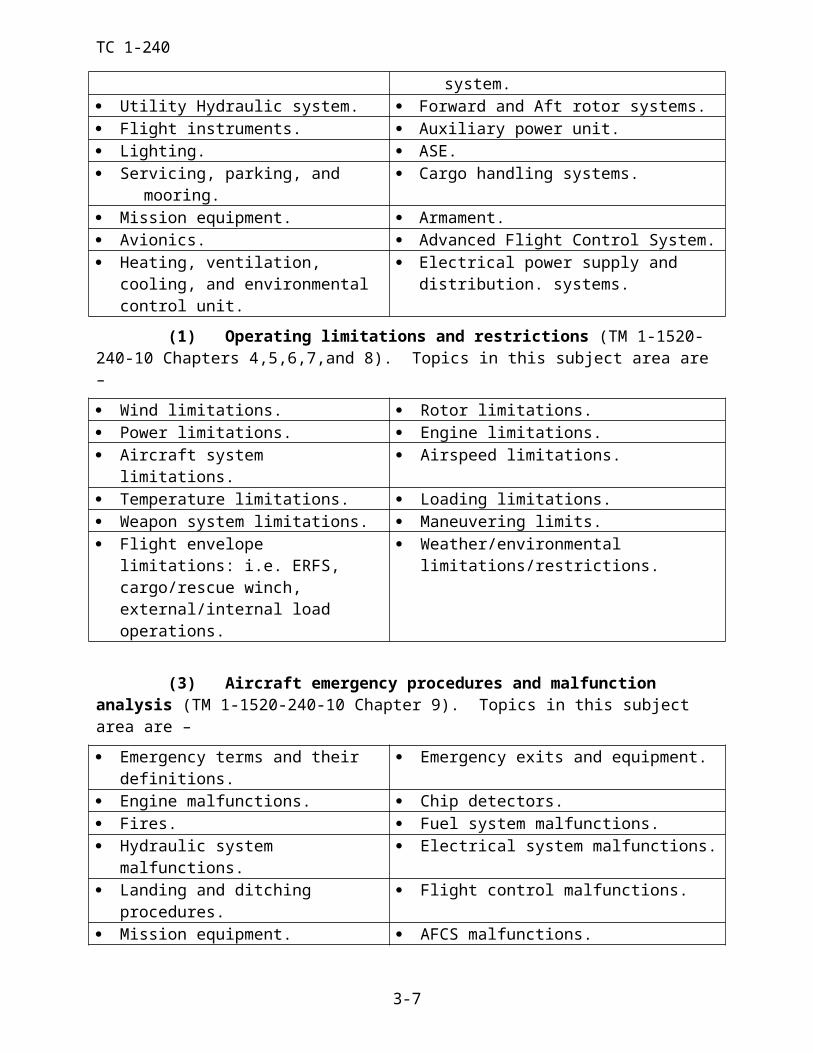
TC 1-240
The FE is responsible to ensure ALL NCMs performing crew duties are briefed on their duties.
NOTE: Safety Harness will be worn and secured when performing crew duties. Seatbelt will be worn at all times when seated unless it interferes with crew duties.
1. Mission overview.2. HIT/PAT Check procedures.3. Aircraft Run-up responsibilities. a. Aft NCM responsibilities. b. Fwd NCM responsibilities.4. Required items, mission equipment, and personnel.5. Crew actions, duties, and responsibilities. a. Sectors of responsibility. (1) Assist in traffic and obstacle avoidance b. Cruise check responsibilities c. Emergency actions. (1) Mission considerations. (2) Emergency action with external load. (3) Egress procedures and rendezvous point. (4) Actions to be performed by FE and CE. d. Perform other duties assigned by the PC. e. Hot/closed circuit refueling.6. Tactical Flight: a. Terrain flight duties. b. Landing Area Reconnaissance. c. Slope Operations. d. External Load Procedures.7. Shut Down Procedures.8. Post Flight Procedures.9. NCM questions, comments, and acknowledgment of NCM mission briefing.
Table 4-2. Suggested format of a NCM crew-briefing checklist.
4-10
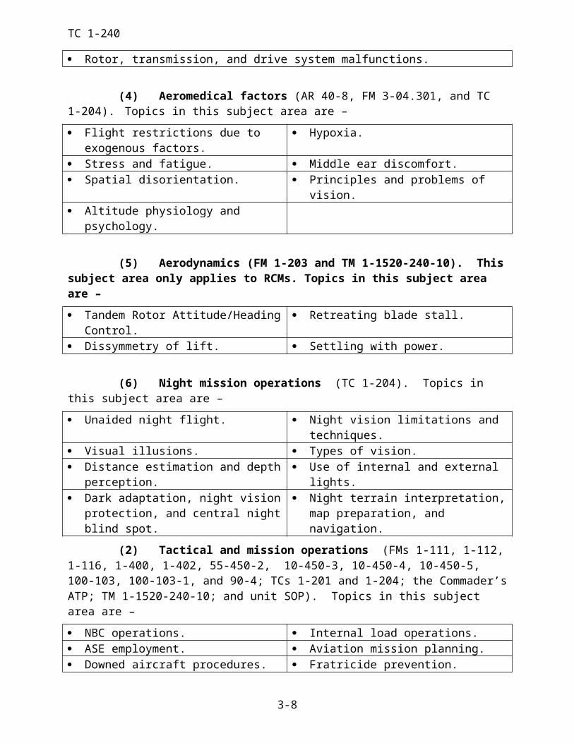
TC 1-240
Task 1004Plan a VFR flight
CONDITIONS: Before VFR flight in a CH-47 helicopter or CH-47FS, given access to weather information; NOTAMs; flight planning aids; necessary charts, forms, and publications; weight and balance information.
STANDARDS: Appropriate common standards plus these additions/modifications:
1. Determine if the aircrew and aircraft are capable of completing the assigned mission.
2. Determine if the flight can be performed under VFR per AR 95-1, applicable FARs/host nation regulations, local regulations, and SOPs.
3. Determine the correct departure, en route, and destination procedures per AR 95-1, appli-cable FARs/host nation regulations, and local regulations and SOPs.
4. Select route(s) and altitudes that avoid hazardous weather conditions, do not exceed air-craft or equipment limitations and conform to VFR cruising altitudes per DOD FLIP.
5. Determine the distance ±1 nautical mile, ground speed ±5 knots, and ETE ±3 minutes for each leg of the flight. Compute magnetic heading(s) ±5 degrees.
6. Determine the fuel required for the mission per AR 95-1, ±100 pounds.
7. Verify that the aircraft will remain with in weight and CG limitations for the duration of the flight per the operator’s manual.
8. Verify aircraft performance data and ensure that power is available to complete the mis-sion per the operator’s manual.
9. Complete and file the flight plan per AR 95-1 and DOD FLIP.
10. Perform mission risk assessment per unit SOP.
DESCRIPTION:
1. Crew actions.
a. The PC may direct the other crew members to complete some elements of the VFR flight planning.
b. The other crew members will complete the assigned elements and report the results to the PC.
2. Procedures. Using appropriate military, FAA, or host-country weather facilities, obtain information about the weather. After ensuring that the flight can be completed under VFR per AR 95-1, check NOTAM’s, CHUMS and other appropriate sources for any restrictions that ap-ply to the flight. Obtain navigational charts that cover the entire flight area, and allow for changes in routing that may be required because of the weather or terrain. Select the course(s) and altitude (s) that will best facilitate mission accomplishment. Determine the magnetic head-ing, ground speed, and ETE for each leg. Compute total distance, flight time, and calculate the required fuel using a CPU-26A/P computer/Weems plotter (or equivalent) or mission planning system. Determine if the duplicate weight and balance forms in the aircraft logbook apply to the mission per AR 95-1. Verify that the aircraft weight and CG will remain within allowable limits for the entire flight. Complete the appropriate flight plan and file with appropriate agency.
4-11
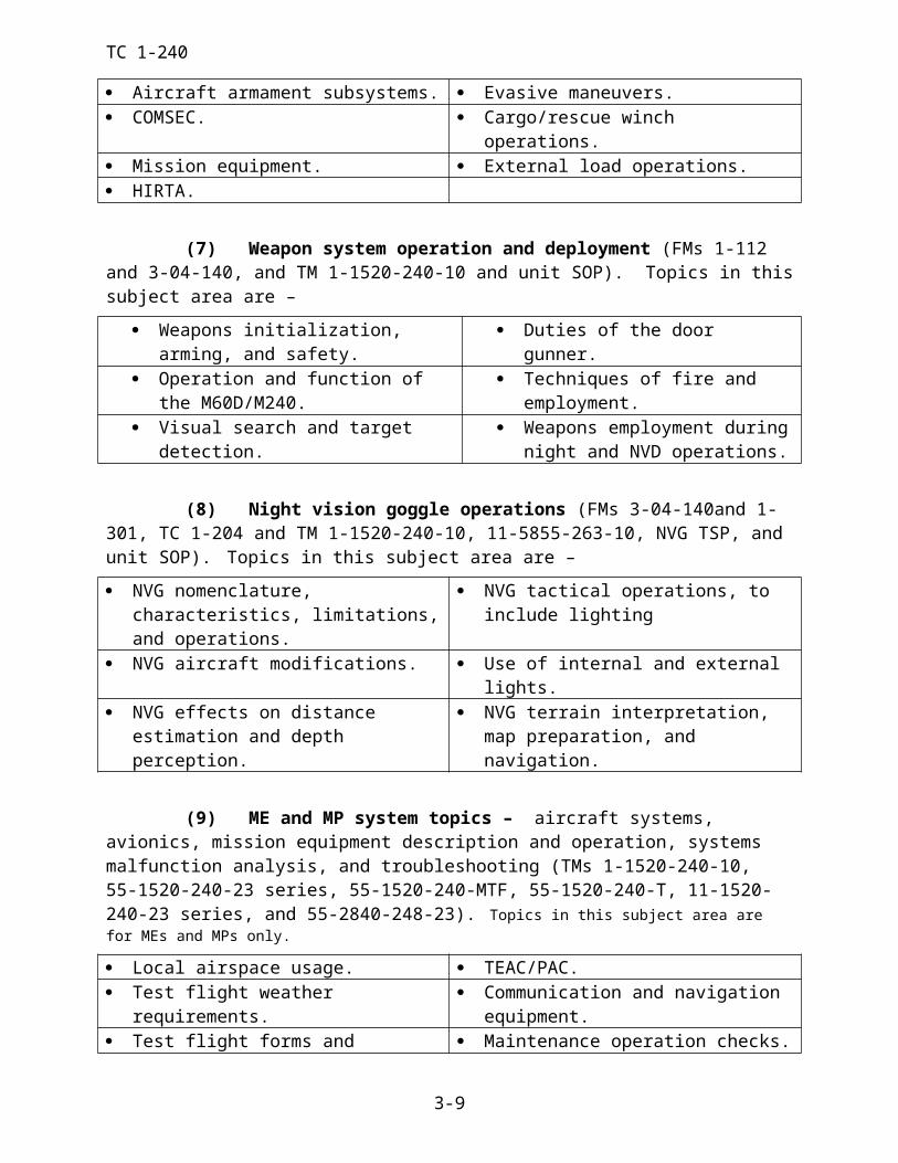
TC 1-240
NIGHT OR NVG CONSIDERATIONS: More detailed planning is necessary at night because of visibility restrictions. Checkpoints used during the day may not be suitable for night or NVG use.
TRAINING AND EVALUATION REQUIREMENTS:
1. Training. Training will be conducted academically.
2. Evaluation. Evaluation will be conducted academically.
REFERENCES: Appropriate common references.
4-12
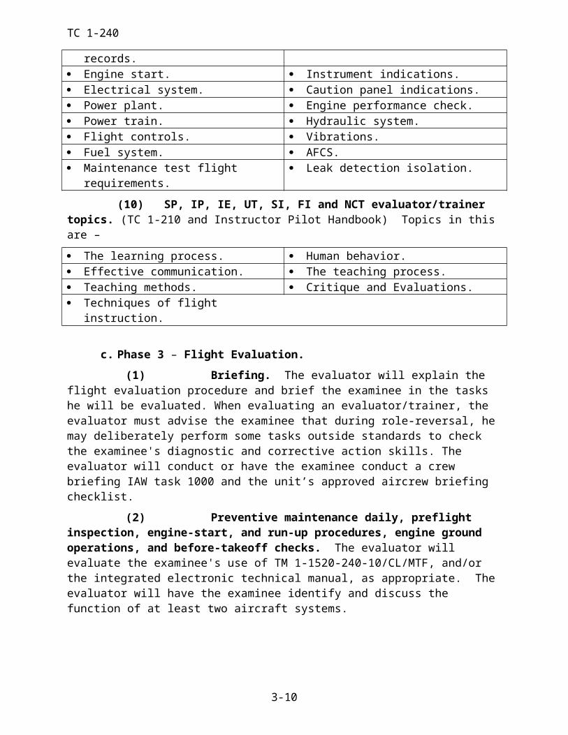
TC 1-240TASK 1006
Plan an IFR flight
CONDITIONS: Before IFR flight in a CH-47 helicopter or a CH-47FS, given access to weather information; NOTAMs; flight planning aids; necessary charts, forms, and publications; weight and balance information.
STANDARDS: Appropriate common standards plus these additions/modifications:
1. Determine if the aircrew and aircraft are capable of completing the assigned mission.
2. Determine if the flight can be performed per AR 95-1, applicable FARs/host nation regu-lations, and local regulations and SOPs.
3. Determine the proper departure, en route, and destination procedures per AR 95-1, appli-cable FARs/host nation regulations, and local regulations and SOPs.
4. Select route(s) and altitudes that avoid hazardous weather conditions, do not exceed air-craft or equipment limitations, and conform to IFR cruising altitudes per DOD FLIP. If off-air-way, determine the course(s) ±5 degrees and determine the off-airway altitude without error.
5. Select an approach that is compatible with the weather, approach facilities, and aircraft equipment; and determine if an alternate airfield is required per AR 95-1, applicable FARs/host nation regulations, and local regulations and SOPs.
6. Determine distance ±1 nautical mile, true airspeed ±5 knots, ground speed ±5 knots, and ETE ±3 minutes for each leg of the flight.
7. Determine the fuel required for the mission per AR 95-1 ±100 pounds.
8. Verify that the aircraft will remain with in weight and CG limitations for the duration of the flight per the operator’s manual.
9. Verify aircraft performance data and ensure that power is available to complete the mis-sion per the operator’s manual.
10. Complete and file the flight plan per AR 95-1 and the DOD FLIP.
11. Perform mission risk assessment per unit SOP.
DESCRIPTION:
1. Crew actions.
a. The PC will ensure that all crew members are current and qualified to perform the mission. He also will determine whether the aircraft is equipped to accomplish the assigned mission. The PC may direct the other RCM to complete some elements of the flight planning.
b. The other RCM will complete the assigned elements and report the results to the PC.
2. Procedures. Using appropriate military, FAA, or host-country weather facilities, obtain information about the weather. Compare destination forecast and approach minimums, and deter-mine if an alternate airfield is required. Ensure that the flight can be completed per AR 95-1. Check the NOTAMs and other appropriate sources for any restrictions that apply to the flight. Obtain navigation charts that cover the entire flight area, and allow for changes in routing or des-tination that may be required because of the weather. Select the route(s) or course(s) and altitude(s) that will best facilitate mission accomplishment. When possible, select preferred rout-ing. Determine the magnetic heading, ground speed, and ETE for each leg, to include flight to
4-13
TC 1-240the alternate airfield if required. Compute the total distance, flight time, and calculate the re-quired fuel using a CPU-26A/P computer/Weems plotter (or equivalent) or mission planning sys-tem. Determine if the weight and balance forms in the aircraft logbook apply to the mission per AR 95-1. Verify that the aircraft weight and CG will remain within allowable limits for the entire flight. Complete the appropriate flight plan and file it with the appropriate agency.
NOTE: GPS IFR navigation is not authorized in the CH-47 until approved by the FAA How-ever, crews should consider and plan for its use as an emergency backup system only. FAA-ap-proved IFR GPS systems possess specific protected terminal instrument procedure data that can-not be altered by the aircrew. The CH-47 GPS system currently does not meet FAA certification requirements.
TRAINING AND EVALUATION REQUIREMENTS:
1. Training. Training will be conducted academically.
2. Evaluation. Evaluation will be conducted academically.
REFERENCES: Appropriate common references.
4-14
TC 1-240
TASK 1010Prepare a performance planning card
CONDITIONS: Given the aircraft takeoff gross weight, the operator’s manual, environmental conditions at departure, cruise, and arrival, a blank DA Form 4887-47 or a computer with the AMCOM approved PPC software.
STANDARDS: Appropriate common standards plus these additions/modifications:
1. Compute performance planning data according to TM 1-1520-240-10 and the descriptions below or use the AMCOM approved performance planning software.
NOTE: Completing the PPC using the operator’s manual is required during the APART Stan-dardization Evaluation.
DESCRIPTION:
1. Crew duties. The PC will compute or direct other rated crew members to compute the aircraft performance data that is required to complete the mission. He will verify the accuracy of the computations, ensure aircraft performance meets mission requirements, and ensure aircraft limitations will not be exceeded.
2. Procedures.
a. Determine and have available aircraft performance data required to complete the mission. DA Form 4887-47 (Figure 4-3) may be used, as an aid to organize perfor-mance-planning data required for the mission. This form will be used for RL progression training, annual ATP evaluations, and when required during other training and evaluations.
b. When significant changes in the mission’s environmental conditions occur, re-compute all affected values. A significant change is defined as an increase of 5° C; 1,000 feet PA; and/or 1,000 pounds gross weight. If no significant change occurs between depar-ture and arrival, the arrival section need not be completed.
NOTE 1: Use forecast conditions for the mission to obtain the most accurate performance data.
NOTE 2: The operator’s manual, Chapters 5, 7 and 9 contain examples for using the perfor-mance data charts. When an example is cited in this description, refer to the appropriate example in Chapter 5, 7 or 9.
NOTE 3: If any computed value exceeds operating limitations enter NA (not available). Additionally, leave value blank when it does not apply.
c. DEPARTURE DATA.
ITEM 1 - OPERATING WT. Record the operating weight of the aircraft. Used for reference only.
ITEM 2 - FUEL WT. Record the takeoff fuel weight. If ERFS is used add to aircraft total. Used for reference only.
ITEM 3 - LOAD. Record the maximum anticipated weight of the load dur-ing the mission profile. Used for reference only.
TC 1-240 ITEM 4a – TAKEOFF GWT NO LOAD. Record the takeoff gross weight.
ITEM 4b – TAKEOFF GWT WITH LOAD. Record the takeoff gross weight.
ITEM 5 – PRESSURE ALT: Record the PA forecast for the time of depar-ture.
ITEM 6 – FAT: Record the FAT forecast for the time of departure.
ITEM 7 – FUEL MANAGEMENT. Use this space if necessary to record the in-flight fuel consumption check, to include fuel burnout and reserve.
ITEM 8 – MAX TQ AVAIL - 10 MIN. Using the Maximum Torque Avail-able 10-Min. chart and the forecast conditions at departure, record the maxi-mum 10 minute torque limit available for dual-engine operation. This number represents the maximum 10 minute torque output (or the maximum 10 minute limit for PTIT) that both engines can produce under these conditions. If the Dual Engine XMSN Torque Limit line is reached prior to the planned PA, en-ter 100%. This represents a transmission limit; the engines may produce power in excess of the transmission limit.
ITEM 9 – MAX TQ AVAIL - (SINGLE ENGINE). Using the Single-En-gine Emergency Power (L-712) or Contingency Torque Available (L-714) chart and the forecast conditions at departure, record the maximum torque available for single-engine operation. This number represents the maximum single engine torque (or the maximum single engine emergency or contin-gency power PTIT) output that one engine can produce. If the Single Engine XMSN Torque Limit line is reached prior to the planned PA, enter 123%. This represents a transmission limit; the engine may produce power in excess of the transmission limit.
ITEM 10 – MAX TORQUE AVAILABLE – 30 MINUTE (L712) or IN-TERMEDIATE TORQUE AVAILABLE (30 MINUTE) (L714). Using the Maximum Torque Available – 30-Minute chart and the forecast conditions at departure, record the maximum 30 minute torque available for dual engine op-eration. This number represents the maximum 30 minute torque output (or the max 30 minute limit for PTIT) that both engines can produce under these con-ditions. If the Dual Engine XMSN Torque Limit line is reached prior to the planned PA, enter 100%. This represents a transmission limit; the engines may produce power in excess of the transmission limit.
ITEM 11 – CONTINUOUS TORQUE AVAIL (DUAL ENGINE). Using the Continuous Torque Available chart, record continuous torque available for dual-engine operation. This number represents the maximum torque output of both engines while still operating at the maximum normal operating range of the PTIT, (or the maximum continuous PTIT). If the Dual-Engine XMSN Torque Limit line is reached prior to the planned PA, enter 100%. This repre-sents a transmission limit; the engines may produce power in excess of the transmission limit.
TC 1-240 ITEM 12 – CONTINUOUS TORQUE AVAIL (SINGLE ENGINE). Us-
ing the Continuous Torque Available chart and the forecast conditions at de-parture, record continuous torque available for single-engine operation. If the Single-Engine XMSN Torque limit line is reached prior to the planned PA, enter 123%. This represents a transmission limit; the engine may produce power in excess of the transmission limit. Reference item 11.
ITEM 13 – PREDICTED HVR TQ IGE (DUAL ENGINE) NO LOAD. Using the Hover chart and the forecast conditions at the time of takeoff, record the torque required to hover at the desired wheel height IGE. The pre-dicted hover torque may be used to confirm pre-calculated aircraft gross weight or to provide the basis for determining a possible torque measuring system malfunction. .
ITEM 14 – PREDICTED HVR TQ OGE (DUAL ENGINE) NO LOAD. Using the Hover chart and forecast conditions at the time of takeoff, record the torque required to hover OGE.
ITEM 15 – PREDICTED HVR TQ IGE (DUAL ENGINE) WITH A LOAD. Using the Hover chart and the forecast conditions at the time of take-off record the predicted torque required to hover at an IGE height that will place the load approximately 10 feet AGL for external loads or IGE for inter-nal loads.
ITEM 16 – PREDICTED HVR TQ OGE (DUAL ENGINE) WITH A LOAD. Using the Hover chart and the forecast conditions at the time of take-off, record the predicted torque required to hover OGE.
ITEM 17 – PREDICTED HVR TQ IGE (SINGLE ENGINE) NO LOAD. Using the Hover chart and the forecast conditions at the time of takeoff record the torque required to hover at the desired wheel height IGE. Compare to sin-gle engine emergency power / contingency power available (item 9) to deter-mine if sufficient power is available to hover single engine at the appropriate wheel height.
ITEM 18 – PREDICTED HVR TQ OGE (SINGLE ENGINE) NO LOAD. Using the hover chart and the forecast conditions at the time of takeoff record the torque required to hover at the desired wheel height OGE. Compare to single engine emergency / contingency power available (item 9) to determine if sufficient power is available to hover single engine OGE.
ITEM 19 - PREDICTED HVR TQ IGE (SINGLE ENGINE) WITH A LOAD. Using the Hover chart and the forecast conditions at the time of take-off record the predicted torque required to hover at an IGE height that will place the load approximately 10 feet AGL for external loads or IGE for inter-nal loads. Compare to single engine emergency power / contingency power available (item 9) to determine if sufficient power is available to hover single engine at the desired wheel height. If the power required exceeds the maxi-mum single-engine emergency torque available, enter NA.
TC 1-240 ITEM 20 - PREDICTED HVR TQ OGE (SINGLE ENGINE) WITH A
LOAD. Using the Hover chart and the forecast conditions at the time of take-off record the predicted torque required to hover OGE. Compare to single engine emergency power / contingency power available (item 9) to determine if sufficient power is available to hover single engine OGE. If the power re-quired exceeds the maximum single-engine emergency torque available, enter NA.
ITEM 21 – GO/NO-GO TQ NO LOAD. Using the Hover chart and the forecast conditions at the time of takeoff, enter the chart at the maximum torque available (10 minute limit) obtained in item 8 above. Move vertically to the OGE line and horizontally to the desired hover altitude. Then move ver-tically down to determine the go/no-go value. The go/no-go torque value, cal-culated at the desired hover altitude, is proportional to the maximum torque available (10 minute limit) at OGE. That is, if the go/no-go torque is ex-ceeded at the desired hover altitude, then maximum torque available (10 minute limit) will be exceeded if OGE maneuvers are attempted. OGE ma-neuvers should not be attempted if go/no-go torque is exceeded.
ITEM 22 – GO/NO-GO TQ WITH LOAD Using the Hover chart and the forecast conditions at the time of takeoff, record the Go / No-Go TQ. Refer-ence item 21.
ITEM 23 – MAX ALLOW. GWT - IGE (DUAL ENGINE). Using the Hover chart or the Hover Ceiling chart (Maximum Gross Weight to Hover) and the forecast conditions, record the maximum allowable gross weight to hover at the desired wheel height IGE.
ITEM 24 – MAX ALLOW. GWT - OGE (DUAL ENGINE). Using the Hover chart or the Hover Ceiling chart (Maximum Gross Weight to Hover) and the forecast conditions, record the maximum allowable gross weight to hover OGE.
ITEM 25 – MAX ALLOW. GWT - IGE (SINGLE ENGINE). Using the Hover chart, the maximum single-engine emergency torque available obtained in item 11 above, and the forecast conditions, record the maximum allowable gross weight to hover single-engine at the desired wheel height IGE. To calcu-late, enter the bottom left portion of the hover chart using the maximum sin-gle-engine emergency torque/ contingency power available calculated in item 9 above. Move vertically up until the 10’/IGE line is intersected, and then move horizontally right to the gross weight chart (bottom right chart). Now enter the upper chart at the planned PA and move horizontally right to the planned temperature. Then move vertically down to the gross weight chart from the top. The intersection of the horizontal and vertical lines represents the Max GW to hover single engine IGE.
TC 1-240 ITEM 26 – MAX ALLOW. GWT - OGE (SINGLE ENGINE). Using the
Hover chart and maximum single-engine emergency torque available obtained in (11) above, record the maximum allowable gross weight to hover for sin-gle-engine operation OGE for forecast conditions. Use the same procedure as item 25 except continue vertically upward to the 80’/OGE line then continue as in item 25 above to obtain the Max GW to hover single engine OGE.
NOTE: The procedure for calculating items 23, 24, 25, and 26 apply both “NO LOAD” and “WITH LOAD”.
ITEM 27 – VALIDATION FACTOR NO LOAD. Using the Hover chart and the forecast conditions at the time of departure, record the predicted torque required to hover at the appropriate hover altitude and at the maximum allowable gross weight for the mission profile. The maximum allowable gross weight for the mission profile is based upon either the maximum gross weight of the aircraft (structural limit), or the maximum allowable gross weight for the operating environment. To calculate, enter the hover chart at the forecast PA at the time of departure and move horizontally right to the forecast tem-perature at the time of departure. Move vertically down to the gross weight chart until the lowest maximum gross weight calculated for the mission pro-file is intersected. Move horizontally left until the desired hover altitude IGE (or OGE if appropriate) is intersected, then move vertically down to the pre-dicted hover torque (dual engine).
ITEM 28 – VALIDATION FACTOR WITH A LOAD. Using the Hover chart and forecast conditions at the time of departure, record the predicted torque required to hover at the appropriate hover altitude and at the maximum allowable gross weight for the mission profile. Calculate the same as in item 27 above.
NOTE: Anticipated weight of expendables, such as fuel, prior to the most limiting point in the mission profile may be factored into mission planning and thus, performance planning.
d. CRUISE DATA.
ITEM 29 – CGI INOP Vne NO LOAD. Using the Airspeed Operating Lim-its chart with inoperative CGI (programmed longitudinal cyclic trim), record the maximum indicated airspeed for forecast cruise conditions. This chart is located in chapter 5 of the operator’s manual.
ITEM 30 – CGI INOP Vne WITH A LOAD. Using the Airspeed Operating Limits chart with inoperative CGI (programmed longitudinal cyclic trim), record the maximum indicated airspeed for forecast cruise conditions.
ITEM 31 – LCT RET Vne NO LOAD. Using the Airspeed Operating Lim-its chart (retracted longitudinal cyclic trim), record the maximum indicated airspeed for forecast cruise conditions. This chart is located in chapter 5 of the operator’s manual.
TC 1-240 ITEM 32 – LCT RET Vne WITH A LOAD. Using the Airspeed Operating
Limits chart (retracted longitudinal cyclic trim), record the maximum indi-cated airspeed for forecast cruise conditions.
ITEM 33 – DRAG FACTOR. Using the Drag chart, the drag area change of the external load, the forecast cruise conditions, and the cruise airspeed in item 41 below, record the additional torque required for cruise with an exter-nal load.
ITEM 34 – PRESSURE ALT. Record the planned cruise PA.
ITEM 35 – FAT. Record the forecast FAT at cruise altitude.
ITEM 36 – MAX TQ AVAIL - 10 MIN. Using the Maximum Torque Available 10-Min. chart and the forecast cruise conditions, record the maxi-mum 10 minute torque limit available for dual-engine operation. Reference item 8.
ITEM 37 – MAX TQ AVAIL - (SINGLE ENGINE). Using the Single-En-gine Emergency Power (L-712) or Contingency Torque Available (L-714) chart and the forecast cruise conditions, record the single engine emergency torque available. Reference item 9.
ITEM 38 – CONTINUOUS TORQUE AVAIL. Using the Continuous Torque Available chart and the forecast cruise conditions, record continuous torque available for dual-engine operation. Reference item 11.
ITEM 39 – CONTINUOUS TORQUE AVAIL (SINGLE ENGINE). Us-ing the Continuous Torque Available chart and the forecast cruise conditions, record continuous torque available for single-engine operation. Reference item 12.
ITEM 40 – MAX R/C and ENDURANCE IAS (DUAL ENGINE) NO LOAD. Using the applicable cruise chart, record the maximum rate of climb and endurance indicated airspeed for the aircraft weight. This airspeed also represents the best single engine airspeed in a single engine configuration.
ITEM 41 – MAX R/C and ENDURANCE IAS (DUAL ENGINE) WITH A LOAD. Using the applicable cruise chart, record the maximum rate of climb and endurance indicated airspeed for the aircraft weight. This airspeed also represents the best single engine airspeed in a single engine configura-tion. Note: The effect of external drag is not accounted for in this procedure.
ITEM 42 – MAX RANGE IAS (DUAL ENGINE) NO LOAD. Using the applicable cruise chart, record the maximum range indicated airspeed for the aircraft weight. If the Vcgi line is intercepted prior to the max range line, en-ter the Vcgi airspeed limit.
TC 1-240 ITEM 43 – MAX RANGE IAS (DUAL ENGINE) WITH A LOAD. Using
the applicable cruise chart, record the maximum range indicated airspeed for the aircraft weight. If the Vcgi line is intercepted prior to the max range line, enter the Vcgi airspeed limit. Note: The effect of external drag is not ac-counted for in this procedure.
ITEM 44 – CRUISE SPEED - IAS (DUAL ENGINE) NO LOAD. Select and enter the desired cruise speed.
ITEM 45 – CRUISE SPEED - IAS (DUAL ENGINE) WITH A LOAD. Select and enter the desired cruise speed.
ITEM 46 – CRUISE SPEED - IAS (SINGLE ENGINE) NO LOAD. Se-lect and enter the desired cruise speed that is not greater than the maximum airspeed for single engine cruise as computed in item 58 below, or slower than minimum airspeed for single engine cruise as computed in item 56 below. The airspeed calculated in item 40 above represents the best single engine air-speed and should be considered when operating single engine.
ITEM 47 – CRUISE SPEED - IAS (SINGLE ENGINE) WITH A LOAD. Select and enter the desired cruise speed that is not greater than the maximum airspeed for single engine cruise as calculated in item 59 below, or slower than minimum airspeed for single engine cruise as calculated in item 57 be-low. The airspeed calculated in item 41 above represents the best single en-gine airspeed and should be considered when operating single engine.
ITEM 48 – CRUISE TORQUE (DUAL ENGINE) NO LOAD. Using the applicable cruise chart, record the torque required to maintain the cruise air-speed listed in item 44 above.
ITEM 49 – CRUISE TORQUE (DUAL ENGINE) WITH A LOAD. Us-ing the applicable cruise chart, calculate the torque required to maintain the cruise airspeed listed in item 45 above. Then, add the additional torque re-quired to cruise based on drag as calculated in item 33 above. If the selected cruise airspeed requires the aircraft to be flown in a time limited engine opera-tion, a lower cruise airspeed must be selected in item 45 and the drag and cruise torque recalculated.
ITEM 50 – CRUISE TORQUE (SINGLE ENGINE) NO LOAD. Using the applicable cruise chart, record the torque required to attain the single en-gine cruise airspeed listed in item 46 above. If the chart does not show single-engine torque, double the torque value shown for dual engines.
ITEM 51 – CRUISE TORQUE (SINGLE ENGINE) WITH A LOAD. Using the applicable cruise chart, record the torque required to attain the sin-gle engine cruise airspeeds listed in item 47 above. If the chart does not show single-engine torque, double the torque value shown for dual engines.
NOTE: For items 49 and 51, adjust the cruise torque to compensate for drag caused by changes in the external configuration. Refer to item 33 for drag factor.
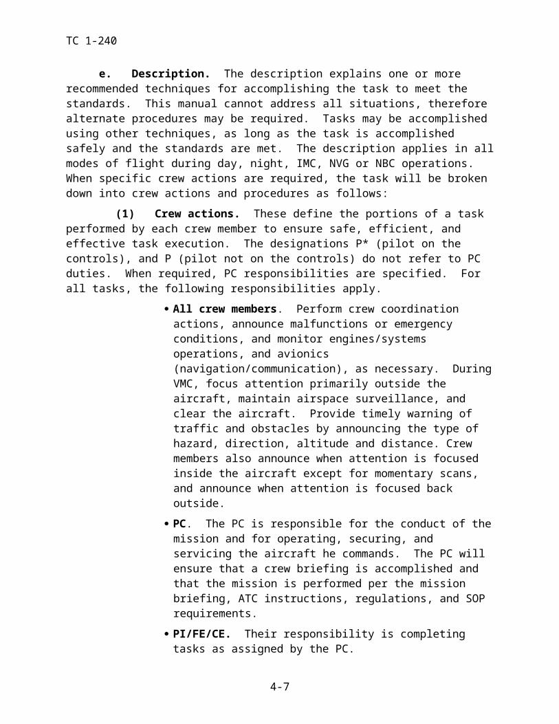
TC 1-240 ITEM 52 – CRUISE FUEL FLOW (DUAL ENGINE) NO LOAD. Using
the appropriate cruise chart and the torque value listed in item 48 above, record the predicted fuel flow.
ITEM 53 – CRUISE FUEL FLOW (DUAL ENGINE) WITH A LOAD. Using the appropriate cruise chart and the torque value listed in item 49 above, record the predicted fuel flow.
ITEM 54 – CRUISE FUEL FLOW (SINGLE ENGINE) NO LOAD. Us-ing the single-engine fuel flow chart and the torque value listed in item 50 above, record the predicted fuel flow. The baseline is 0º, therefore increase/decrease this fuel flow by 1% for every 10C change in temperature.
ITEM 55 – CRUISE FUEL FLOW (SINGLE ENGINE) WITH A LOAD. Using the single-engine fuel flow chart and the torque value listed in item 51 above, record the predicted fuel flow. Increase/decrease this fuel flow by 1% for every 10C change in temperature.
ITEM 56 – MINIMUM SINGLE ENGINE IAS NO LOAD. Using the ap-propriate cruise chart, enter the chart at 50 percent of the computed single-en-gine emergency torque available for cruise conditions. Move vertically to the first intersection of the actual gross weight line. If the intersection is below the maximum R/C and endurance airspeed line, record the airspeed that will allow continued single-engine operation. If the torque line is to the left of the actual gross weight line and does not intersect the actual gross weight line, enter NA for the minimum airspeed. When the torque line is to the right of the actual gross weight line and does not intersect the actual gross weight line below the maximum R/C and endurance airspeed line, enter OGE for the minimum air-speed that will allow continued single-engine operation.
ITEM 57 - MINIMUM SINGLE ENGINE IAS WITH A LOAD. Using the appropriate cruise chart, enter the chart at 50 percent of the computed sin-gle-engine emergency torque available for cruise conditions. Move vertically to the first intersection of the actual gross weight line. If the intersection is be-low the maximum R/C and endurance airspeed line, record the airspeed that will allow continued single-engine operation. If the torque line is to the left of the actual gross weight line and does not intersect the actual gross weight line, enter NA for the minimum airspeed. When the torque line is to the right of the actual gross weight line and does not intersect the actual gross weight line be-low the maximum R/C and endurance airspeed line, enter OGE for the mini-mum airspeed that will allow continued single-engine operation. Note: The effect of external drag is not accounted for in this procedure
TC 1-240 ITEM 58 – MAXIMUM SINGLE ENGINE IAS NO LOAD. Using the ap-
propriate cruise chart, enter the chart at 50 percent of the computed single-en-gine emergency torque available for cruise conditions. Move vertically to the intersection of the actual gross weight line above the maximum R/C and en-durance airspeed line. Record the maximum airspeed that will allow contin-ued single-operation. If the torque line is to the left of the actual gross weight line and does not intersect the actual gross weight line, enter NA for the maxi-mum airspeed.
ITEM 59 – MAXIMUM SINGLE ENGINE IAS WITH A LOAD. Using the appropriate cruise chart, enter the chart at 50 percent of the computed sin-gle-engine emergency torque available for cruise conditions. Move vertically to the intersection of the actual gross weight line above the maximum R/C and endurance airspeed line. Record the maximum airspeed that will allow con-tinued single-operation. If the torque line is to the left of the actual gross weight line and does not intersect the actual gross weight line, enter NA for the maximum airspeed. Note: The effect of external drag is not accounted for in this procedure
ITEM 60 – MAX GWT SINGLE ENG. Using the single-engine service ceiling chart, located in chapter 9 of the operator’s manual, record the maxi-mum allowable gross weight that will allow sustained single-engine flight at the planned cruise PA to be flown for the mission. This value is based on max endurance / rate of climb airspeed.
ITEM 61 – SESC (SINGLE ENGINE SERVICE CEILING). Using the Single-Engine Service Ceiling chart, located in chapter 9 of the operator’s manual, record the maximum altitude attainable that will allow sustained sin-gle-engine flight using the actual aircraft GWT and forecast conditions. This value is based on max endurance / rate of climb airspeed.
e. ARRIVAL DATA. Not required if arrival environmental data has not signifi-cantly increased (5C, 1000 Ft PA, or 1000 pounds GWT) from the departure data when computing the PPC manually.
ITEM 62a – LANDING GWT. Record the estimated landing gross weight.
ITEM 62b – LANDING GWT WITH A LOAD. Record the estimated landing gross weight.
ITEM 63 – PRESSURE ALT. Record the forecast PA at destination at ETA.
ITEM 64 – FAT. Record the forecast FAT at destination at ETA.
ITEM 65 – MAX TQ AVAIL - 10 MIN. Using the Maximum Torque Available 10-Min. chart and the forecast arrival conditions, record the maxi-mum torque available for dual-engine operation. Reference item 8.
TC 1-240 ITEM 66 – MAX TQ AVAIL - (SINGLE ENGINE). Using the single Sin-
gle-Engine Emergency Power (L-712) or Contingency Torque Available (L-714) chart and the forecast arrival conditions, record the maximum torque available for single-engine operation. Reference item 9.
ITEM 67 – MAX TQ AVAIL - 30 MIN (L712) or INTERMEDIATE TORQUE AVAILABLE (L714). Using the Maximum Torque Available – 30-Minute chart and the forecast arrival conditions, record the maximum torque available (30-minute) for dual engine operation. Reference item 10.
ITEM 68 – PREDICTED HVR TQ - IGE (DUAL ENGINE) NO LOAD. Using the Hover chart, and the forecast arrival conditions record the torque re-quired to hover at the desired wheel height IGE for forecast arrival conditions. Reference item 13.
ITEM 69 – PREDICTED HVR TQ - OGE (DUAL ENGINE) NO LOAD. Using the Hover chart, and the forecast arrival conditions record the torque re-quired to hover at the desired wheel height OGE. Reference item 14.
ITEM 70 – PREDICTED HVR TQ - IGE (DUAL ENGINE) WITH A LOAD. Using the Hover chart, and the forecast arrival conditions record the predicted torque required to hover at a height that will place the load approxi-mately 10 feet AGL and IGE. Reference item 15.
ITEM 71 – PREDICTED HVR TQ - OGE (DUAL ENGINE) WITH A LOAD. Using the Hover chart, and the forecast arrival conditions record the predicted torque required to hover at a height that will place the load approxi-mately 10 feet AGL and OGE. Reference item 16.
ITEM 72 – PREDICTED HVR TQ - IGE (SINGLE ENGINE) NO LOAD. Using the Hover chart, and the forecast arrival conditions record the torque required to hover at the desired wheel height IGE. Reference item 17.
ITEM 73 – PREDICTED HVR TQ - OGE (SINGLE ENGINE) NO LOAD. Using the Hover chart, and the forecast arrival conditions record the torque required to hover at the desired wheel height OGE. Reference item 18.
ITEM 74 - PREDICTED HVR TQ - IGE (SINGLE ENGINE) WITH A LOAD. Using the Hover chart, and the forecast arrival conditions record the predicted torque required to hover at a height that will place the load approxi-mately 10 feet AGL and IGE. If the power required exceeds the maximum single-engine emergency torque available, enter NA. Reference item 19.
ITEM 75 - PREDICTED HVR TQ - OGE (SINGLE ENGINE) WITH A LOAD. Using the Hover chart and the forecast arrival conditions, record the predicted torque required to hover at a height that will place the load approxi-mately 10 feet AGL and OGE. If the power required exceeds the maximum single-engine emergency torque available, enter NA. Reference item 20.
TC 1-240 ITEM 76 – MAX ALLOW. GWT - IGE (DUAL ENGINE). Using the
Hover chart and the maximum torque available obtained in item 65 above or the Hover ceiling chart (Maximum Gross Weight to Hover) and the forecast arrival conditions, record the maximum allowable gross weight to hover at the desired wheel height IGE. Reference item 23.
ITEM 77 – MAX ALLOW. GWT - OGE (DUAL ENGINE). Using the Hover chart and the maximum torque available obtained in item 65 above or the hover ceiling chart (maximum gross weight to hover), and the forecast ar-rival conditions record the maximum allowable gross weight to hover OGE for forecast arrival conditions. Reference item 24.
ITEM 78 – MAX ALLOW. GWT - IGE (SINGLE ENGINE). Using the Hover chart, maximum single-engine emergency torque available obtained in item 66 above, and the forecast arrival conditions record the maximum allow-able gross weight to hover for single-engine operation at the desired wheel height IGE. Reference item 25.
ITEM 79 – MAX ALLOW. GWT - OGE (SINGLE ENGINE). Using the Hover chart, maximum single-engine emergency torque available obtained in item 66 above, and the forecast arrival conditions record the maximum allow-able gross weight to hover for single-engine operation OGE. Reference item 26.
NOTE: Items 76, 77, 78, and 79 apply to both “NO LOAD” and “WITH A LOAD”.
TRAINING AND EVALUATION REQUIREMENTS: Training and evaluation will be con-ducted academically.
REFERENCE: TM 1-1520-240-10.
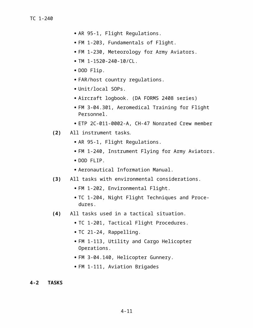
TC 1-240
CH-47 PERFORMANCE PLANNING CARDFor use of this form, see TC 1-240: The proponent agency is TRADOC
DEPARTURE DATAOPERATING WT: 1 FUEL WT: 2 LOAD: 3 TAKEOFF GWT: 4a / 4b
PRESSURE ALT: 5 FAT: 6
FUEL MANAGEMENT: 7 QTY___________TIME_____________ PPH _______________ BURNOUT_________ RESERVE __________
DUAL ENGINE SINGLE ENGINE
NO LOAD WITH LOAD NO LOAD WITH LOAD
MAX TQ AVAIL – 10 MIN / S/E TQ 8 9
MAX TORQUE AVAIL. – 30 MINUTE10
CONTINUOUS TORQUE AVAIL. 11
12
PREDICTED HVR TQ – IGE / OGE 13 / 14 15 / 16
17 / 1819 / 20
GO / NO-GO TQ 21 22
MAX ALLOW. GWT – IGE / OGE 23 / 24 25 / 26
VALIDATION FACTOR 27 28CRUISE DATA
CGI INOP Vne: 29 / 30 LCT RET Vne: 31 / 32 DRAG FACTOR: 33
PRESSURE ALT: 34 FAT: 35NO LOAD WITH LOAD NO LOAD WITH LOAD
MAX TQ AVAIL – 10 MIN / S/E TQ 36 37
CONTINUOUS TORQUE AVAIL.38
39
MAX R/C AND ENDURANCE IAS 40 41
MAX RANGE IAS 42 43
CRUISE SPEED – IAS 44 45
46 47
CRUISE TORQUE (+ DRAG FACTOR)48 49 50
51
CRUISE FUEL FLOW 52 5354 55
MINIMUM SINGLE ENGINE IAS 56 57
MAXIMUM SINGLE ENGINE IAS 58 59
MAX GWT S/E / SESC 60 / 61ARRIVAL DATA
LANDING GWT: 62a / 62bDUAL ENGINE SINGLE ENGINE
PRESSURE ALT: 63 FAT: 64 NO LOAD WITH LOAD NO LOAD WITH LOAD
MAX TQ AVAIL - 10 MIN / S/E TQ 65 66
MAX TORQUE AVAIL. – 30 MINUTE 67
PREDICTED HVR TQ – IGE / OGE 68 / 69 70 / 71 72 / 73 74 / 75
MAX ALLOW. GWT – IGE / OGE 76 77 78 79DA FORM 4887-47
Figure 4-3. Performance Planning Card
TC 1-240TASK 1012
Verify aircraft weight and balance
CONDITIONS: Given crew weights, aircraft configuration, mission cargo, passenger data, the operator’s manual, and completed DD Form(s) 365-4 from the aircraft logbook.
STANDARDS: Appropriate common standards plus these additions/modifications:
1. Verify that CG and gross weight remain within aircraft limits for the duration of the flight per the operator’s manual.
2. Identify all mission or flight limitations imposed by weight or CG.
DESCRIPTION:
1. Crew actions.
a. PC will brief crew members on any limitations.
b. Crew members will continually monitor aircraft loading during mission (i.e. fuel transfers, sling loads, cargo load) to ensure CG remains within limits.
2. Procedures.
a. Using the completed DD Forms 365-4 from the aircraft logbook, verify that air-craft gross weight and CG will remain within the allowable limits for the entire flight. Note gross weight and/or loading restrictions/aircraft limitations. If there is no completed DD Form 365-4 that meets the requirements of AR 95-1, prepare a DD Form 365-4 IAW the op-erator’s manual and TM 55-1500-342-23.
b. Verify the aircraft CG in relation to CG limits at predetermined times during the flight when an aircraft’s configuration requires special attention, for example, when it is a critical requirement to keep a certain amount of fuel in a particular tank. Conduct CG checks for fuel, sling, and cargo loading operations.
TRAINING AND EVALUATION REQUIREMENTS:
1. Training. Training will be conducted academically.
2. Evaluation. Evaluation will be conducted orally or academically.
REFERENCES: Appropriate common references plus TM 55-1500-342-23.
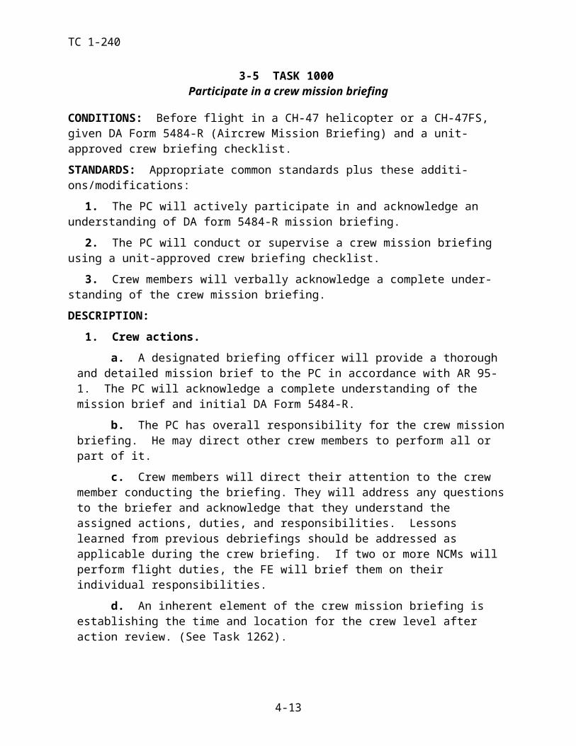
TC 1-240TASK 1014
Operate ALSE
CONDITIONS: Given the appropriate ALSE for the mission.
STANDARDS: Appropriate common standards plus these additions/modifications:
1. Inspect/perform operational checks on ALSE
2. Use ALSE IAW the appropriate operator’s manual/instructions for each piece of equip-ment.
3. Assist passengers in the use of ALSE.
DESCRIPTION:
1. Crew actions. The PC will verify that all required ALSE equipment is onboard the air-craft and meets all serviceability criteria before takeoff.
2. Procedures. Based on mission requirements, obtain the required ALSE. Inspect equip-ment for serviceability and perform required operational checks. Secure the required ALSE in the aircraft per AR 95-1, FM 1-302, TM 1-1520-240-10/CL, and the unit SOP. Brief passengers in the use of ALSE.
TRAINING AND EVALUATION REQUIREMENTS:
1. Training. Training will be conducted academically.
2. Evaluation. Evaluation will be conducted academically.
REFERENCES: Appropriate common references plus the following:
TM 5-4220-202-14TM 55-1680-317-23&PTM 55-1680-351-10NCM ETP 2C-011-0002-ATM 1-8415-216-12&P
TC 1-240TASK 1016
Perform internal load operations
CONDITIONS: In a CH-47 helicopter loaded with passengers/cargo, or academically.
STANDARDS: Appropriate common standards plus these additions/modifications:
1. Rated.
a. Ensure that a thorough passenger briefing has been conducted and that a pas-senger manifest is on file, if applicable. Conduct the briefing per the operator’s manual/CL and the unit SOP.
b. Verify that the aircraft will remain within gross weight and CG limitations.
c. Ensure that the passengers and cargo are properly restrained.
d. Ensure that floor-loading limits are not exceeded.
e. Ensure cargo meets restraint criteria.
2. Nonrated.
a. Perform a thorough passenger briefing and ensure that a passenger manifest is on file, if applicable. Conduct the briefing per the operator’s manual/CL and the unit SOP.
b. Load the aircraft per the load plan, if applicable.
c. Ensure that floor-loading limits are not exceeded.
d. Secure passengers and cargo.
e. Ensure cargo meets restraint criteria.
DESCRIPTION:
1. Crew actions.
a. The PC with assistance from the FE will formulate a load plan, ensure that a DD Form 365-4 is verified, if required, and ensure that the aircraft will be within gross weight and CG limits. He will ensure that the crew loads the cargo, proper tiedown procedures are used, and any passengers receive a briefing. The PC will determine whether the aircraft is capable of completing the assigned mission and will ensure that aircraft limitations will not be exceeded.
b. The P will perform a hover power check before takeoff and ensure the maximum allowable gross weight of the aircraft is not exceeded.
c. The NCM will ensure passengers are seated and are wearing seat belts before takeoff. He will monitor passengers and cargo during the flight for security.
2. Procedures.
a. Load cargo per the cargo plan or DD Form 365-4, as appropriate. Correctly se-cure and restrain all cargo to meet restraint criteria per the appropriate manuals. For addi-tional information, see Task 1012, Prepare / Verify aircraft weight and balance form.
b. Brief passengers for the flight and seat them according to the load plan or DD Form 365-4, as appropriate. Conduct the briefing per Operator’s Manual/CL, unit SOP and information about the mission. Ensure that the passengers understand each element of the briefing.
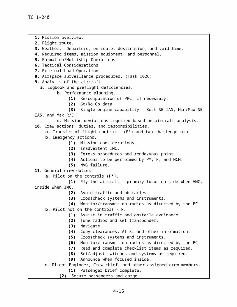
TC 1-240NOTE 1: If the aircraft is not shut down for loading, a passenger briefing may be impractical. Passengers may be pre-briefed or passenger-briefing cards may be used per local directives or the unit SOP.
NOTE 2: Hazardous cargo will be handled, loaded, and transported per AR 95-27 and the oper-ator’s manual/CL .
TRAINING AND EVALUATION REQUIREMENTS:
1. Training. Training may be conducted in the aircraft or academically.
2. Evaluation. Evaluation may be conducted in the aircraft or academically.
REFERENCES: Appropriate common references plus the following:
AR 95-27FM 55-450-1/2TM 38-250TM 55-1500-342-23DA Pam 738-751TM 1-1520-240-10

TC 1-240TASK 1022
Perform preflight inspection
CONDITIONS: With a CH-47 helicopter and given the operator’s manual/CL.
STANDARDS: Appropriate common standards plus these additions/modifications:
1. Rated.
a. Perform the preflight inspection per the operator’s manual/CL.
b. Enter appropriate information on the appropriate forms per DA Pamphlet 738-751.
2. Nonrated. Assist in all before-preflight and preflight duties per the operator’s manual/CL, unit SOP and for the designated duty position.
DESCRIPTION:
1. Crew actions.
a. The PC is responsible for ensuring that a preflight inspection is conducted using the operator’s manual/CL. The PC may direct other crew members to complete elements of the preflight inspection as applicable, and will verify that all checks have been completed IAW the operator’s manual/CL. He will expediently report any aircraft discrepancies that may affect the mission and will ensure that the appropriate information is entered on the ap-propriate forms per DA Pamphlet 738-751.
b. The crew members will complete the assigned elements and report the results to the PC.
2. Procedures.
a. Ensure the preflight inspection is conducted per the operator’s manual/CL. Verify that all pre-flight checks have been completed and ensure that the crew members en-ter the appropriate information on the appropriate forms per DA Pamphlet 738-751.
b. As applicable, the PC will ensure that all pertinent data has been loaded into the aircraft; for example, FM, COMSEC fills, GPS keys and waypoints, etc.
c. If circumstances permit, accomplish preflight inspection during daylight hours.
d. The NCM will ensure all cowlings and equipment are secured upon completion of preflight.
NIGHT OR NVG CONSIDERATIONS: If performing the preflight inspection during the hours of darkness, a flashlight with an unfiltered lens to supplement available lighting should be used. Hydraulic leaks, oil leaks, and other defects are difficult to see using a flashlight with a colored lens. Ensure that internal and external lighting is operational. TC 1-204 contains details on preflight inspection at night.
TRAINING AND EVALUATION REQUIREMENTS:
1. Training. Training will be conducted at the aircraft.
2. Evaluation. Evaluation will be conducted at the aircraft.
REFERENCES: Appropriate common references plus the following:
DA Pamphlet 738-751
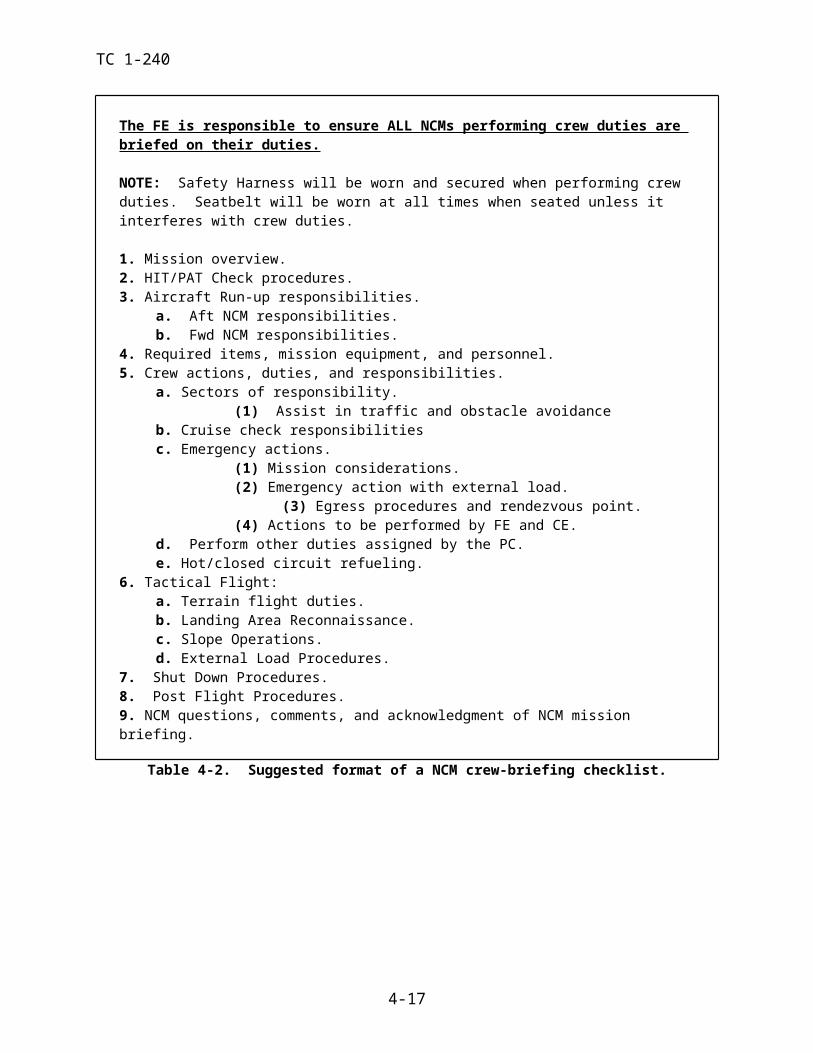
TC 1-240TASK 1024
Perform before-starting engine through before leaving helicopter checks
NOTE
Anytime a NCM is outside the aircraft, or inside the aircraft with the engines operating and the left hand escape panel is removed, or the upper cabin door is open, or the ramp cargo door is IN, the NCM’s visor should be down.
CONDITIONS: In a CH-47 helicopter or a CH-47FS and given an Operator’s Manual/CL.
STANDARDS: Appropriate common standards plus these additions/modifications.
1. Perform procedures and checks per the operator’s manual/CL.
2. Enter appropriate information on DA Form 2408-12, -13, and 13-1.
DESCRIPTION:
1. Crew actions.
a. Each crew member will complete the required checks pertaining to his assigned crew duties per the operator’s manual/CL. Crew members will coordinate with each other prior to entering data into aircraft systems.
b. The P will read the checklist and announce APU and engine starts.
c. All crew members will clear the area around the aircraft before APU start and each engine start.
d. The NCMs will perform duties as required by his duty position and as directed by the PC, IAW unit SOP, while maintaining situational awareness.
e. Enter appropriate information on DA Forms 2408-12, 2408-13/13-1 and the HIT/PAT log IAW unit SOP and DA PAM 738-751.
f. If two or more NCMs will perform flight duties, the FE will determine which crew member will perform specific portions of each task.
g. Secure the aircraft after completion of the flight per the operator’s manual, TM 1-1520-240-23 series, TM 1-1500-250-23, and the unit SOP.
2. Procedures. Perform the before-starting engine through before leaving helicopter checks per the operator’s manual/CL. The call and response method will be used, as appropriate. The crew member reading the checklist will read the complete checklist item. The crew member per-forming the check will answer with the appropriate response. For example, for the call "Swivel switch - As required" the response might be” Swivel switch, Steer." “As required” is not an ap-propriate response. Responses that don't clearly communicate action or information should not be used. After flight correctly enter all information required on the appropriate DA Forms. Dur-ing APU start, the NCM will be outside of the aircraft to ensure the area is clear and to perform fireguard duties. During engine start, the NCM will assume a position 45 degrees from the front of the engine at the rotor blade tip to ensure that the aircraft is clear and ready for the engine start. The NCM and/or pilots will complete the post flight per the operator’s manual/CL . Upon completion of required maintenance and inspection, the NCM will moor the aircraft and install required protective covers and security devices.
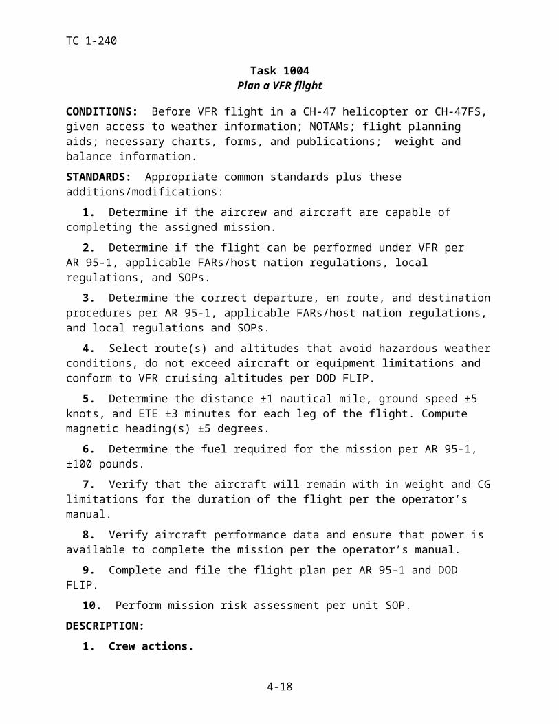
TC 1-240NIGHT OR NVG CONSIDERATIONS: Before starting the engines, ensure that all internal and external lights are operational and set. Internal lighting levels must be high enough to easily see the instruments and to start the engines without exceeding operating limitations.
SNOW/SAND/DUST CONSIDERATIONS: Ensure all rotating components and inlets/ex-hausts are clear of ice and/or snow prior to starting APU/engines.
TRAINING AND EVALUATION REQUIREMENTS:
1. Training. Training may be conducted in the aircraft or the simulator.
2. Evaluation. Evaluations will be conducted in the aircraft.
REFERENCES: Appropriate common references plus the following:
DA Pamphlet 738-751TM 55-5840-248-23NCM ETP 2C-011-0002-A
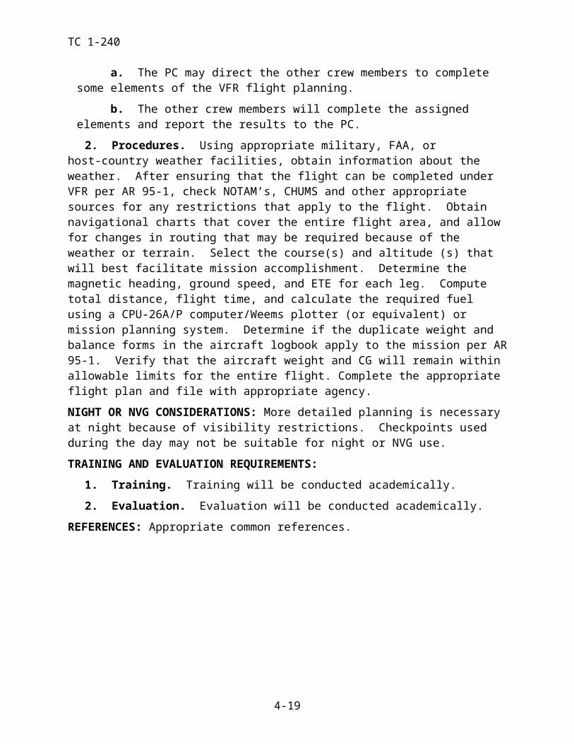
TC 1-240TASK TASK 1026
Maintain airspace surveillance
WARNING
While moving about the cabin area during flight, the NCM(s) must be secured to a 5,000-lb. tiedown fitting in the cabin area. NCM(s) will not secure their restraining harness to the ramp.
CONDITIONS: In a CH-47 helicopter or a CH-47FS in VMC.
STANDARDS: Appropriate common standards plus these additions/modifications:
1. Announce drift or altitude changes, clear the aircraft, and immediately inform other crew members of all air traffic or obstacles that pose a threat to the aircraft.
2. Announce when attention will be focused inside the aircraft.
3. Maintain airspace surveillance in assigned scan sectors.
4. When landing, the crew will confirm the suitability of the area and that the aircraft is clear of obstacles.
DESCRIPTION:
1. Crew actions.
a. The PC will brief airspace surveillance procedures prior to the flight. The briefing will include areas of responsibility and scan sectors.
b. The P* will announce his intent to perform a specific maneuver and will remain focused outside the aircraft. He is responsible for clearing the aircraft and obstacle avoid-ance.
c. Crew members will assist in clearing the aircraft and will provide adequate warning of obstacles, unusual drift, or altitude changes. They will announce when their at-tention is focused inside the aircraft and again when attention is reestablished outside.
d. When landing, the crew will confirm the suitability of the area and that the air-craft is clear of obstacles. The NCM(s) will move about the aircraft as necessary to ensure total coverage.
2. Procedures.
a. Maintain close surveillance of the surrounding airspace. Keep the aircraft clear from other aircraft and obstacles by maintaining visual surveillance (close, mid and far ar-eas) of the surrounding airspace. Inform the crew immediately of air traffic or obstacles that pose a threat to the aircraft. Call out the location of traffic or obstacles by the clock, alti-tude, and distance method. (The 12 o'clock position is at the nose of the aircraft.) Give dis-tance in miles or fractions of miles for air traffic and in miles or feet for ground obstacles, as appropriate. When reporting air traffic, specify the type of aircraft, if known. The altitude of the air traffic should be reported as the same altitude, higher, or lower than the altitude at which you are flying.
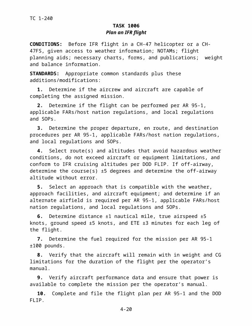
TC 1-240b. Prior to changing altitude, visually and verbally clear the aircraft for hazards
and obstacles inclusive of what is ahead, above, and to the left and right of the aircraft.
c. Prior to performing a descending flight maneuver, it may sometimes be desir-able to perform a clearing “S” turns to the left or right. The clearing “S” turns will provide the aircrew with a greater visual scan area.
d. During a hover or hovering flight, inform the P* of any unannounced drift or altitude changes. When landing, the crew will confirm the suitability of the area.
NIGHT OR NVG CONSIDERATIONS: The use of proper scanning techniques will assist in detecting traffic and obstacles, and in avoiding spatial disorientation. Hazards such as wires are difficult to detect.
TRAINING AND EVALUATION REQUIREMENTS:
1. Training. Training may be conducted in the aircraft or simulator.
2. Evaluation. Evaluation will be conducted in the aircraft.
REFERENCES: Appropriate common references.
TC 1-240TASK 1027
Perform Health Indicator Test (HIT) / Power Assurance Test (PAT) check
CONDITIONS: In a CH-47 helicopter or CH-47FS.
STANDARDS: Appropriate common standards plus these additions/modifications:
1. Complete the HIT check per the engine Health Indicator Program Log or the PAT check per the PAT log and TM 1-1520-240-10.
DESCRIPTION:
1. Crew actions.
a. The P will perform the checks in sequence. He should coordinate with, and di-rect assistance from the P* and NCM as necessary.
b. The P, will ensure the P* is familiar with HIT/PAT check procedures.
2. Procedures - GROUND. The P briefs and coordinates with the P* and NCM as neces-sary. Position the aircraft into the prevailing wind. Set the brakes and direct assistance as neces-sary. Confirm the flight controls are neutral and the thrust control is in the ground detent. Direct the P* to monitor the flight controls and maintain aircraft control when the thrust control is not in the ground detent. Direct the NCM to assist with maintaining obstacle avoidance, and advise the cockpit concerning the movement of other aircraft operating in the immediate area.
a. Perform the HIT or PAT in accordance with applicable reference.
b. Once the check has been completed for both engines, return to the checklist.
3. Procedures – HOVER. The P briefs and coordinates with the P* and NCM as necessary. Direct the P* to maintain hover position and heading while maintaining orientation outside the cockpit. Direct the NCM to assist with maintaining obstacle avoidance, and advise the cockpit concerning other aircraft and/or hazards in the area.
a. Perform the PAT in accordance with applicable references. Manipulation of the ECL’s may not be required if the torques are in the appropriate ranges for the PAT.
b. Once the check has been completed for both engines continue with the checklist.
4. Procedures – IN FLIGHT. The in-flight PAT procedure will be conducted only if envi-ronmental conditions prevent the check on the ground or hover. The P briefs and coordinates with the P* and NCM as necessary. Direct the P* to maintain assigned altitude, heading and air-speed while maintaining orientation outside the cockpit. Direct the NCM to assist with maintain-ing obstacle avoidance, and advise the cockpit concerning other aircraft and/or hazards in the area.
a. Establish the aircraft at the appropriate airspeed while maintaining 100% RRPM.
b. Perform the PAT in accordance with the applicable reference. Once the check has been completed for both engines, confirm a Systems Check and continue with the mis-sion. Manipulation of the ECL’s may not be required if the torques are in the appropriate ranges for the PAT.
TRAINING AND EVALUATION REQUIREMENTS:
1. Training. Training may be conducted in the aircraft, flight simulator, or academically.
2. Evaluation. Evaluation will be conducted in the aircraft.

TC 1-240REFERENCES: Appropriate common references.
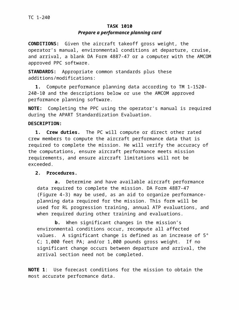
TC 1-240TASK 1028
Perform hover power check
CONDITIONS: In a CH-47 helicopter or a CH-47FS, at an appropriate hover height, and with performance planning information available.
STANDARDS: Appropriate common standards plus these additions/modifications:
1. Position the aircraft in the vicinity of the take off point and in the direction of take off at the appropriate hover height.
2. Determine that sufficient power is available to complete the mission by comparing actual torque to predicted torque, go/no-go torque, and the validation factor obtained during perfor-mance planning.
3. Determine if single-engine hover capability exists.
4. Determine that aircraft performance is sufficient to complete the mission.
DESCRIPTION:
1. Crew actions.
a. The PC will determine whether the aircraft is capable of completing the as-signed mission and will ensure that aircraft limitations will not be exceeded.
b. The P* will announce his intent to bring the aircraft to a stationary hover for a hover power check. During the ascent, check for proper control response and C.G. Remain focused outside the aircraft and announce when the aircraft is stabilized at the desired hover altitude. Use a 10-foot stationary hover near the takeoff point and in direction of takeoff when performing a hover power check unless the mission or terrain constraints dictate oth-erwise. If different hover height is required, use that height during performance planning to compute go/no-go torque, validation factor torque, and predicted hover torque.
c. During the accent, the P will monitor the torque. If validation factor is ap-proached prior to reaching desired hover height, the P will announce this in sufficient time so that appropriate action can be taken by the P*. The P will monitor the aircraft instru-ments, note engine N1’s, PTIT’s, engine oil temperatures, engine oil pressures, and deter-mine if sufficient fuel is available to complete the mission and verify the power check. He will compare the actual hover performance data to the computed data on the PPC and an-nounce the results to the P*. If go/no-go torque for the desired hover height is indicated prior to reaching the planned hover height used during performance planning, the P will in-form the P* that out of ground effect maneuvers cannot be conducted . The PC will confirm the go/no-go torque and adjust the mission as required.
d. The NCM will remain focused primarily outside the aircraft to assist in clearing and to provide adequate warning of obstacles.
2. Procedures.
a. Use the hover height computed during performance planning when performing this task unless the mission or terrain constraints dictate otherwise. If another hover height is required, use that height to compute go/no-go and validation factor torque. See Task 1038, Perform Hovering Flight
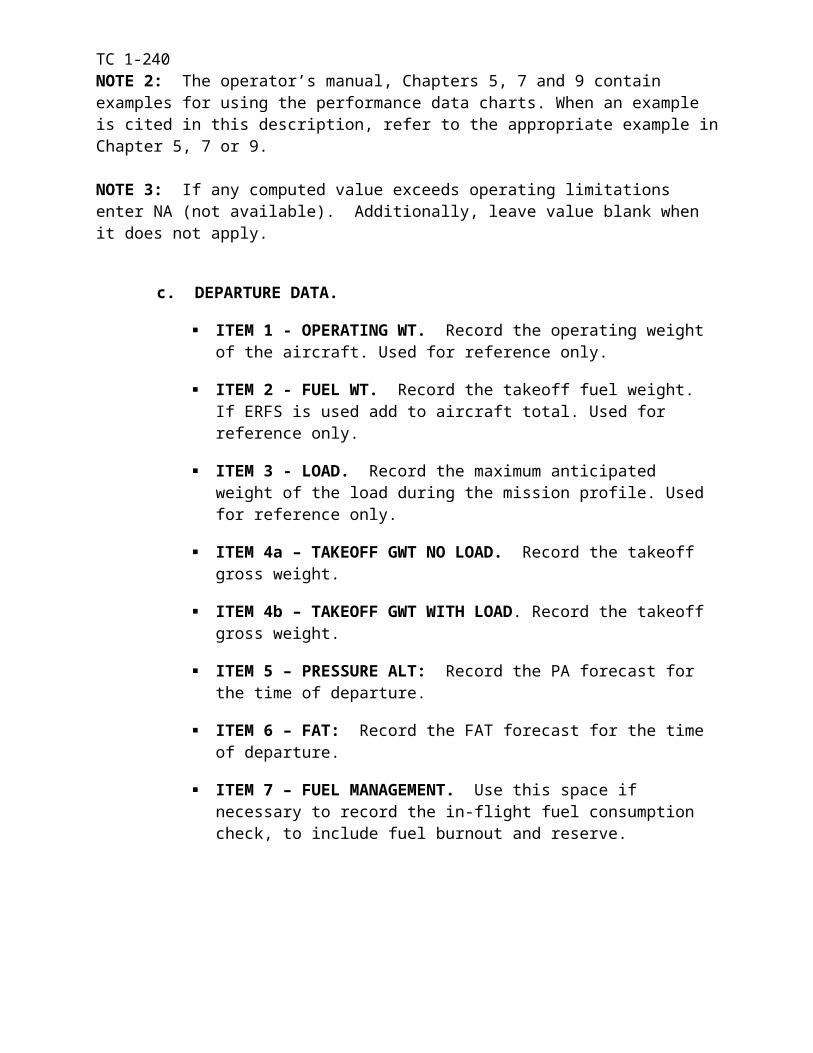
TC 1-240b. At desired hover height, monitor the aircraft instruments and verify the power
check. The P will determine if single engine capability exists and will compare actual torque to predicted torque, go/no-go torque, and the validation factor. He will ensure that aircraft limitations are not exceeded.
c. The PC will ensure that aircraft performance and fuel are sufficient to complete the mission.
NOTE: If the torque required to maintain a stationary hover does not exceed the go/no-go torque OGE, any maneuver requiring OGE/IGE power or less may be attempted. If the torque required to maintain a stationary hover exceeds the go/no-go torque OGE but does not exceed the validation factor IGE, all IGE maneuvers may be attempted. If the torque required to maintain a stationary hover exceeds the computed validation factor, the maximum gross weight may have been exceeded for the environmental conditions present. Anytime the gross weight or environmental conditions increase significantly; the crew will perform additional hover power checks and, recompute all PPC values. Significant increase is defined as 1000 lbs gross weight, 1000 feet PA, and/or 5° C.
TRAINING AND EVALUATION REQUIREMENTS:
1. Training. Training will be conducted in the aircraft or flight simulator.
2. Evaluation. Evaluation will be conducted in the aircraft or flight simulator.
REFERENCES: Appropriate common references.
TC 1-240TASK 1032
Perform radio communication procedures
CONDITIONS: In a CH-47 helicopter or a CH-47FS.
STANDARDS: Appropriate common standards plus these additions/modifications:
1. Rated Crew members.
a. Check and operate aircraft avionics.
b. Establish radio contact with the desired unit or ATC facility. When communi-cating with ATC facilities, use correct radio communication procedures and phraseology per the AIM, DOD FLIP and DOT/FAA 7110.65.
c. Operate intercom system.
d. Perform or describe two-way radio failure procedures per the DOD FLIP or host country regulations.
2. Nonrated Crew members. Use the intercommunication system to communicate with the crew.
DESCRIPTION:
1. Crew actions.
a. The PC will determine radio frequencies per mission requirements during the crew briefing and will indicate whether the P* or P will establish and maintain primary communications.
b. The P* will announce information not monitored by the P.
c. The P will adjust avionics to required frequencies. He will copy pertinent infor-mation and announce information not monitored by the P*.
d. During normal operations, the NCM will monitor external communications so as not to interrupt when external communications are being transmitted or received. (Moni-toring external communications may not be desirable during operations requiring extensive internal communication; for example, external loads, hoist, or emergencies.)
e. Crew actions for two-way radio failure:
(1) P* or P will announce two-way radio failure to all crew members.
(2) The PC will direct the efforts to identify and correct the avionics malfunction.
(3) The P* will focus outside the aircraft VMC or inside IMC on the instruments, as appropriate, but should not participate in troubleshooting the malfunction.
(4) The P will remain focused primarily inside the aircraft to identify and correct the avionics malfunction
f. Crew Actions for Aircraft Intercom failure: PC will direct assistance from the crew to try and determine the malfunction and correct it. Alternate actions may include: switching to a different ICS box, changing microphone cords if available, hooking up to a different ICS station, hand and arm signals, or passing notes. If the problem cannot be cor-rected, the PC will determine the course of action which may vary from landing as soon as practical to landing as soon as possible.
TC 1-2402. Procedures.
a. Adjust avionics to the required frequencies. Continuously monitor the avionics as directed by the PC. When required, establish communications with the desired facility. Moni-tor the frequency before transmitting. Transmit the desired/required information. Use the cor-rect radio call sign when acknowledging each communication. When advised to change fre-quencies, acknowledge instructions. Select the new frequency as soon as possible unless in-structed to do so at a specific time, fix, or altitude. Use radio communication procedures and phraseology as appropriate for the area of operations. Use standard terms and phraseology for all intercommunications
b. Procedures for two-way radio failure. Attempt to identify and correct the mal-functioning radio and announce the results. If two-way radio failure is confirmed, comply with procedure outlined in the Flight Information Handbook or Host country regulations.
TRAINING AND EVALUATION REQUIREMENTS:
1. Training. Training may be conducted in the aircraft or simulator.
2. Evaluation. Evaluation may be conducted in the aircraft or simulator.
REFERENCES: Appropriate common references plus the following:
AIMP/CGDOD FLIP DOT/FAA 7110.65
TC 1-240
TASK 1034Perform ground taxi
CAUTION
While turning during a two-wheel taxi, the P* must avoid the forward gear contacting the ground.
CONDITIONS: In a CH-47 helicopter or a CH-47FS on a suitable surface, with the before-taxi/after landing check completed, and the aircraft cleared.
STANDARDS: Appropriate common standards plus these additions/modifications:
1. Rated.
a. Maintain a constant speed appropriate for conditions.
b. Maintain the desired ground track.
c. Maintain flight controls in accordance with the operator’s manual.
2. Nonrated.
a. Perform applicable checks according to TM 1-1520-240-CL and the unit SOP when read by the P.
b. Immediately inform the RCM’s of any observed discrepancy or malfunction.
c. Clear the aircraft.
d. Use hand-and-arm signals, if required, per FM 21-60.
DESCRIPTION:
1. Two-Wheel Taxi Crew actions.
a. The P* will announce his intent to begin the two-wheel taxi operations, the taxi plan, and the intended direction of any turns. He will remain focused primarily outside the aircraft. The P and NCM will assist him in clearing the aircraft.
b. The P* will call for the before-taxi check or the taxi check, as appropriate. The P will read the appropriate taxi check. He will ensure that the aft wheel swivel switch is locked and that the AFCS select switch is at BOTH or OFF. He will have the NCM in the ramp area visually confirm swivel lock actuators are locked.
c. The P* will advise the P to monitor ground control limitations and LCT opera-tion. Initially, the P* will position the cyclic, as necessary, not to exceed 2 inches aft. He will release the brakes, as required, and raise the thrust lever until the forward landing gear are clear of the ground. The P* will maintain directional control with the pedals and speed with the thrust control.
(1) During forward taxi, the P* will raise the thrust lever to slow or stop the aircraft. He will lower it to increase forward speed. If desired, the P* will lower the forward gear to the ground while taxiing in a straight line or when all movement is stopped.
TC 1-240
(2) For back taxi, the P* will raise the thrust lever until the aircraft begins to move rearward. He will maintain directional control with the pedals and speed with the thrust lever. The P* will lower the thrust lever to slow or stop the aircraft. He will raise the thrust lever to increase rearward speed.
NOTE 1. Prior to two-wheel taxi, the PC will have one the FE/CE visually confirm that the both aft gear are in the trail position and that both aft wheel swivel lock actuators are locked.
NOTE 2. The P* may use lateral cyclic inputs to assist with directional control. These inputs are normally required when taxiing in a crosswind.
2. Four-Wheel Taxi Crew actions.
a. The P* will announce his intent to begin the four-wheel taxi and state his taxi plan. He will call for the before-taxi check or the taxi check, as appropriate. The P will read the appropriate taxi check. He will ensure that the swivel switch is at STEER and that the AFCS select switch is OFF.
b. The P will advise the P* that he has control of the brakes and the power steer-ing. The P* will monitor LCT operation and take care to not exceed ground control limita-tions.
c. All crew members will clear the aircraft as necessary. The P* will raise the thrust lever to start forward movement and then lower it to ground detent. All thrust move-ments will be announced.
(1) The P will maintain the taxi speed with moderate brake applications, and call for thrust application/reduction as appropriate.
(2) The P will slowly rotate the power steering control knob to turn the aircraft in the desired direction. During taxi at light gross weights, the P may have to advise the P* to apply aft cyclic to prevent a loss of steering control.
d. When the NCM is required outside the aircraft during taxiing, he will position himself where the P*/P can clearly see his hand-and-arm signals or will remain attached to the aircraft communication system.
NOTE 1. Prior to four-wheel taxi, visually confirm that the both aft gear are in the trail position.
NOTE 2. During four-wheel taxi, the P must not allow the power steering control knob to spring back to the neutral position.
NOTE 3. If the LCT actuators cycle between RET and GND because of light loading on the aft landing gear, it may be necessary to apply up to 2 inches of aft cyclic. If this action does not prevent further LCT cycling, set the cyclic trim switch to MANUAL. If the LCTs are not at GND manually set them to that position. When taxiing is completed and prior to performing a takeoff to a hover, set the cyclic trim switch to AUTO.
NIGHT OR NVG CONSIDERATIONS: The landing light should be used for unaided ground taxi and the searchlight with installed IR band pass light filter when wearing NVG. The use of proper scanning techniques will assist in detecting obstacles that must be avoided.
SNOW/SAND/DUST CONSIDERATIONS: If ground reference is lost because of blowing snow/sand/dust, lower the thrust lever, neutralize the flight controls, and apply wheel brakes until visual reference is reestablished. Use caution when taxiing near other maneuvering aircraft be-cause of limited visual references and relative motion illusion.
TC 1-240
NOTE 1. Because of decreased visual references and relative motion illusions, limit ground speed to a rate appropriate for the conditions.
NOTE 2. At night, use of the landing, search, or anti-collision lights may cause spatial disori-entation in blowing snow/sand/dust.
TRAINING AND EVALUATION REQUIREMENTS:
1. Training. Training may be conducted in the aircraft or simulator.
2. Evaluation. Evaluation will be conducted in the aircraft.
REFERENCES: Appropriate common references.
TC 1-240
TASK 1038Perform hovering flight
CONDITIONS: In a CH-47 helicopter or a CH-47FS and the aircraft cleared.
STANDARDS: Appropriate common standards plus these additions/modifications:
1. Perform a smooth, controlled ascent to hover.
2. Perform a smooth, controlled descent with minimal drift at touchdown.
3. Maintain ground track, ±5 feet during hover taxi.
4. Maintain a constant rate of turn not to exceed 90 degrees within 4 seconds.
DESCRIPTION:
1. Crew actions.
a. The P* will announce his intent to perform a specific hovering flight maneuver and will remain focused primarily outside the aircraft to monitor altitude and avoid obsta-cles. He will ensure and announce that the aircraft is cleared prior to turning or repositioning the aircraft. He will announce when he terminates the maneuver.
b. The P and NCM will assist in clearing the aircraft and provide adequate warn-ing of obstacles, unannounced drift or altitude changes. They will announce when their at-tention is focused inside the aircraft and again when their attention is reestablished outside.
2. Procedures.
a. Takeoff to a hover. Position the cyclic, as necessary, not to exceed 2 inches aft while all four landing gear are on the ground, and maintain heading with the pedals. Smoothly raise the thrust lever and adjust the cyclic to make a vertical ascent to a 10-foot aft gear height unless mission requirements dictate another altitude. Then release the brakes as necessary.
b. Hovering flight. Adjust the cyclic to maintain a stationary hover or to hover in the desired direction. Control heading with the pedals and maintain altitude with the thrust lever. Maintain a constant hover speed appropriate for the conditions. To return to a sta-tionary hover, apply cyclic in the opposite direction while maintaining heading with the ped-als and altitude with the thrust lever.
c. Hovering turns.
(1) Around the nose. With the aircraft stationary, pick a point slightly for-ward of the nose. Control the direction and rate of turn with the cyclic, pedals, and maintain alti-tude with the thrust lever. (Cross-control of the cyclic and pedals is required to pivot around the nose.)
(2) Around the center cargo hook. With the aircraft at a stationary hover and the cargo hook over the pivot point, apply pedal in the desired direction of turn. Maintain a stationary position over the pivot point with the cyclic. Control the rate of turn with the pedals and maintain altitude with the thrust lever.
(3) Around the tail. With the aircraft at a stationary hover and the pivot point under the tail, apply cyclic and pedal in the direction of the intended turn. Use cyclic and pedal to control the rate of turn and movement. Maintain hover altitude with the thrust lever.
TC 1-240
d. Landing from a hover. Lower the thrust lever to affect a smooth rate of de-scent until the aft gear contacts the ground. Coordinate thrust lever reduction with aft cyclic, as necessary, to maintain pitch attitude and to stop forward movement. Smoothly lower the thrust lever to allow the forward gear to contact the ground. Continue to lower the thrust lever to ground detent, neutralize the controls, and apply brakes to stop forward movement. If sloping conditions are suspected or anticipated, see Task 1062, Perform Slope Operations.
NOTE 1. The P and NCM should assist the P* in maintaining the position of the aircraft over the pivot point.
NOTE 2. When landing from a hover to an unimproved area, the crew must check for obstacles under the aircraft.
NIGHT OR NVG CONSIDERATIONS:
1. Movement over areas of limited contrast, such as tall grass, water, or desert tends to cause spatial disorientation. Seek hover areas that provide adequate contrast and use proper scanning techniques. If disorientation occurs, apply sufficient power and execute an ITO Task 1170. If a take off is not feasible, try to maneuver the aircraft forward and down to the ground to limit the possibility of touchdown with sideward or rearward movement.
2. When performing operations during unaided night flight, ensure that the searchlight or landing light (white light) is in the desired position. Use of the white light will impair night vi-sion for several minutes. Therefore, exercise added caution if resuming flight before reaching full dark adaptation.
SNOW/SAND/DUST CONSIDERATIONS: During ascent to a hover, if visual references do not deteriorate to an unacceptable level, continue ascent to the desired hover altitude.
1. 10-foot hover taxi. During takeoff to a hover, simultaneously accelerate the aircraft to a ground speed that keeps the snow/sand/dust cloud just aft of the cabin door.
NOTE 1. Maintain optimum visibility by observing references close to the aircraft. Exercise caution when operating in close proximity to other aircraft or obstacles.
NOTE 2. When visual references deteriorate making a 10-foot hover taxi unsafe, determine whether to abort the maneuver, ground taxi, air taxi, or perform an ITO Task 1170.
2. 20- to 100-foot air taxi. Use this maneuver when it is necessary to move the aircraft over terrain that is unsuitable for hover taxi. Initiate air taxi the same as a 10-foot hover, but increase altitude normally not more than 100 feet and accelerate to a safe airspeed appropriate for condi-tions.
NOTE 1. Ensure that an area is available to safely decelerate and land the aircraft. Under certain conditions, such as adverse winds, it may be necessary to perform a traffic pattern to optimize conditions at the desired termination point.
NOTE 2. Hovering OGE reduces available ground references and may increase the possibility of spatial disorientation. Be prepared to transition to instruments and execute an ITO or Unusual Attitude Recovery Task 1182 if ground reference is lost.
NOTE 3. At night, use of landing, search, or anti-collision lights may cause spatial disorientation while in blowing snow/sand/dust.
CONFINED AREA CONSIDERATIONS: Select good references to avoid unanticipated drift. All crew members must be focused primarily outside for obstacle avoidance.
TC 1-240
TRAINING AND EVALUATION REQUIREMENTS:
1. Training. Training may be conducted in the aircraft or simulator.
2. Evaluation. Evaluation will be conducted in the aircraft.
REFERENCES: Appropriate common references.
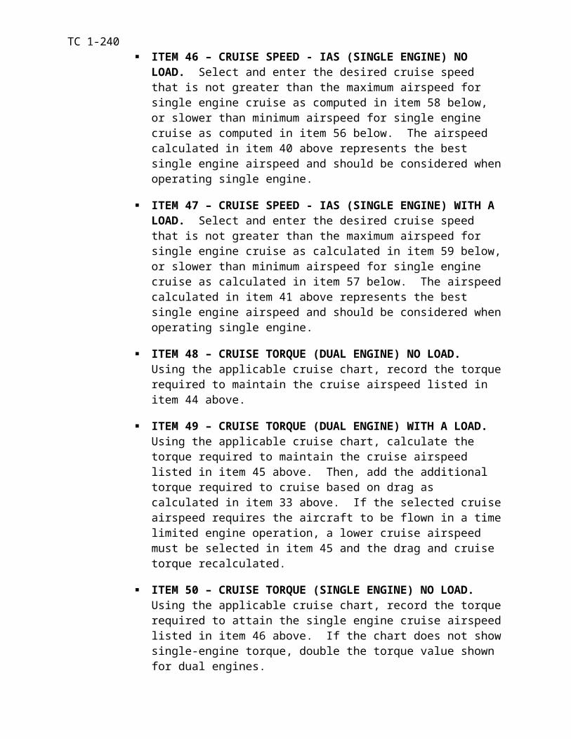
TC 1-240TASK 1040
Perform VMC takeoff
CONDITIONS: In a CH-47 helicopter or a CH-47FS with the hover power and before-takeoff checks completed.
STANDARDS: Appropriate common standards plus these additions/modifications:
1. Properly clear the aircraft.
2. Maintain takeoff heading ± 10 degrees below 50 feet AGL.
3. Maintain ground track aligned with takeoff direction.
4. Maintain aircraft in trim above 50-feet AGL or as appropriate for transition to terrain flight.
5. Maintain takeoff power until reaching minimum single engine airspeed, desired climb air-speed, or transition to mission profile.
DESCRIPTION:
1. Crew actions.
a. The PC will determine the direction of takeoff by analyzing the tactical situa-tion, wind, long axis of the takeoff area, and the lowest obstacles. He will ensure that re-quired power is available by comparing the information from the PPC to the hover power check. He will ensure that the required fuel for the mission is available by comparing the required fuel on board the aircraft to the PPC. If the fuel on board is inadequate, add suffi-cient fuel, abort, or revise the mission.
b. The P* will remain focused primarily outside the aircraft throughout the ma-neuver to provide obstacle clearance. He will announce whether the takeoff is from the ground or from a hover and his intent to abort or alter the takeoff. He will select reference points to assist in maintaining the takeoff flight path.
c. The P and NCM will announce when ready for takeoff and will remain focused primarily outside the aircraft to assist in clearing and to provide adequate warning of obsta-cles.
d. The P will monitor power requirements and advise the P* if power limits are being approached. The P and NCM will announce when their attention is focused inside the aircraft and again when attention is reestablished outside.
2. Procedures:
a. From the ground.
(1) The P* will announce his intent to take off from the ground. He will focus his attention primarily outside the aircraft but will occasionally crosscheck the flight instruments.
(2) All crew members will clear the aircraft
(3) The P* will select reference points to maintain ground track. With the cyclic and pedals in the neutral position, the P* will release the brakes and raise the thrust lever until the aircraft is airborne and accelerating. All landing gear should leave the ground at the same time. As the aircraft leaves the ground, the P* will apply forward cyclic as required to smoothly accelerate through ETL at an altitude appropriate for the terrain and obstacles. He will
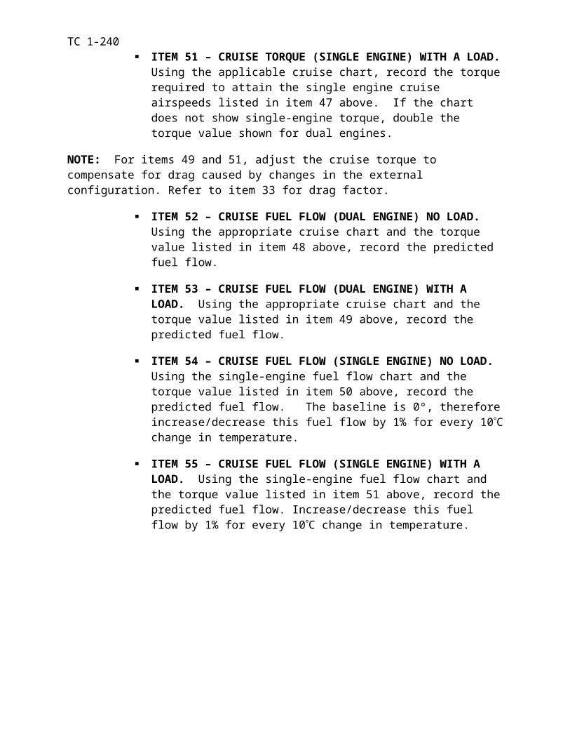
TC 1-240adjust the cyclic as necessary to continue the acceleration (approximately 5 degrees nose down), obtain the desired climb airspeed, and maintain ground track. The P* will position the thrust lever as necessary to clear obstacles in the flight path and obtain the desired rate of climb. He will use the pedals to maintain heading when below 50 feet AGL and in trim when above 50 feet AGL. When the P* obtains the desired climb airspeed, he will adjust the cyclic as necessary to stop the acceleration. He will adjust the thrust lever to continue or to stop the rate of climb. The P will confirm LCT operation.
b. From a Hover.
(1) The P* will announce his intent to take off from a hover. He will focus his attention primarily outside the aircraft.
(2) All crew members will clear the aircraft.
(3) The P* will select reference points to maintain ground track. He will apply forward cyclic to smoothly accelerate the aircraft through ETL while adjusting the thrust lever, as required, to maintain the appropriate hover height. The P* will perform the rest of the maneu-ver as for a takeoff from the ground.
NOTE 1. Performing this maneuver in certain environments may require hover OGE power. Evaluate each situation for power required versus power available, such as terrain flight takeoff.
NOTE 2. The P* must avoid excessive and unnecessary nose-low accelerative attitudes.
NOTE 3. The NCMs should remain seated during this maneuver.
NIGHT OR NVG CONSIDERATIONS:
1. If sufficient illumination exists to view obstacles, accomplish the takeoff in the same way as a VMC takeoff during the day. Visual obstacles, such as shadows, should be treated the same as physical obstacles.
2. If sufficient illumination does not exist, perform an altitude-over-airspeed takeoff by ap-plying takeoff power first followed by a slow acceleration to ensure obstacle clearance. The P* may perform the takeoff from a hover or from the ground.
a. Maintain the takeoff power setting until reaching climb airspeed. Adjust power as re-quired to establish the desired rate of climb and cyclic to maintain the desired airspeed. Cross-checking instruments while assisting with obstacle avoidance. The P* and NCM should main-tain orientation outside the aircraft and concentrate on obstacle avoidance. The P should make all internal checks.
b. Reduced visual references during the takeoff and throughout the ascent at night may make it difficult to maintain the desired ground track. Knowledge of the surface wind direction and velocity will assist in maintaining the desired ground track.
c. Use proper scanning techniques to avoid spatial disorientation.
d. When performing operations during unaided night flight, ensure that the searchlight or landing light (white light) is in the desired position. Use of the white light may impair night vi-sion for several minutes. Therefore, exercise added caution if resuming flight before reaching fully dark adaptation.
SNOW/SAND/DUST CONSIDERATIONS: Apply thrust and cyclic as required to ascend vertically. As the aircraft leaves the ground, maintain heading with the pedals and a level atti-tude with the cyclic. As the aircraft clears the snow/sand/dust cloud and clears the barriers, ac-celerate to climb airspeed and trim the aircraft.
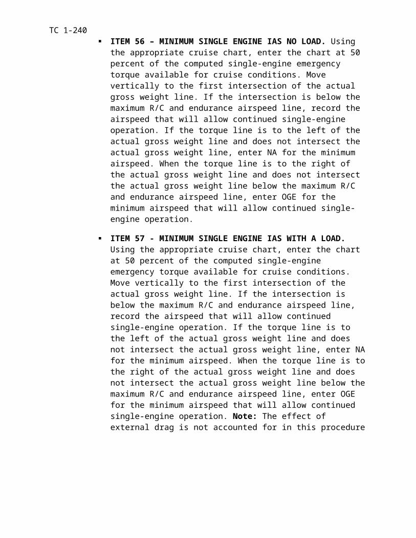
TC 1-240NOTE 1. In some cases, applying pitch with the thrust lever to blow away loose snow/sand/dust from around the aircraft is beneficial before performing this maneuver.
NOTE 2. Be prepared to transition to instruments and execute an ITO if ground reference is lost.
NOTE 3. At night, use of the landing, search, or anti-collision may cause spatial disorientation while in blowing snow/sand/dust.
CONFINED AREA CONSIDERATIONS: Before departure, confirm the takeoff plan. Per-form a hover power check, if required. Reposition the aircraft, if desired, to afford a shallower departure angle and minimize power requirements. During departure, adjust the cyclic and the thrust lever as required to establish a constant departure angle to clear obstacles. All crew mem-bers must be focused primarily outside for obstacle avoidance.
MOUNTAIN/PINNACLE/RIDGELINE CONSIDERATIONS: Analyze winds, obstacles, and density altitude. Perform a hover power check, if required. Determine the best takeoff di-rection and path for conditions. After clearing obstacles, accelerate the aircraft to the desired air-speed.
NOTE: Where drop-offs are located along the takeoff path, the aircraft may be maneuvered downslope to gain airspeed.
MUD/MUSKEG/TUNDRA CONSIDERATIONS: Perform one of the following takeoff tech-niques:
1. From dry muskeg/tundra areas. A vertical takeoff may be best in drier areas where the aircraft has not sunk into the muskeg/tundra or where obstacles prohibit motion. Smoothly in-crease the thrust lever until the crew confirms that the wheels/skis are free. Adjust controls as necessary to perform a VMC takeoff.
2. From wet areas. In wet areas where the aircraft is likely to have sunk or is stuck in the mud/muskeg/tundra, the following technique may be best: With the cyclic in the neutral posi-tion, smoothly increase the thrust lever. As hover power is approached, adjust the cyclic as nec-essary to ascend vertically to break the suction of the wheels/skis. When free, adjust the con-trols as necessary to perform a VMC takeoff.
NOTE: Before performing operations in a mud/muskeg/tundra environment, it is important to understand dynamic rollover and DASH actuator characteristics.
TRAINING AND EVALUATION REQUIREMENTS:
1. Training. Training may be conducted in the aircraft or simulator.
2. Evaluation. Evaluation will be conducted in the aircraft.
REFERENCES: Appropriate common references.
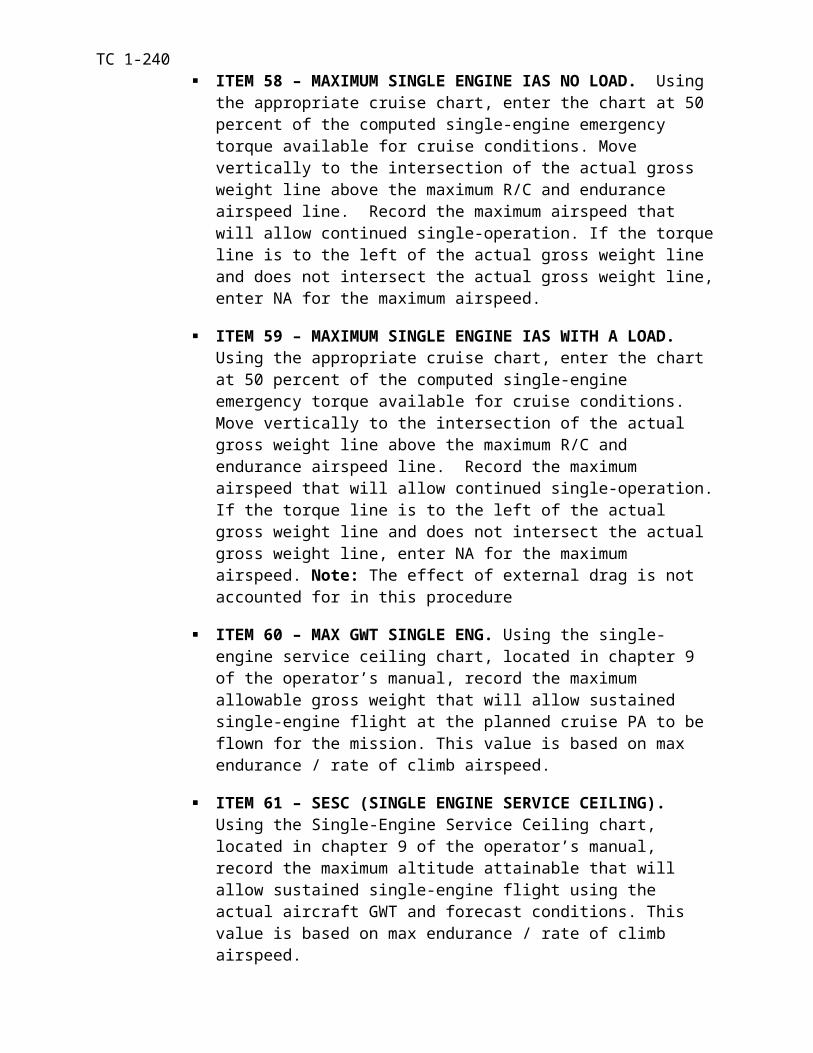
TC 1-240TASK 1042
Perform cruise check procedures
CAUTION
Flight crew members will use a safety restraining harness at all times while moving about the cabin area. If crew members are not performing any tasks or maneuvers, they should remain seated with seat belts secured.
CONDITIONS: In a CH-47 helicopter or a CH47FS.
STANDARDS: Appropriate common standards plus these additions/modifications:
1. Rated.
a. Call for the cruise check 15 to 30 minutes after takeoff or after entry into the mis-sion profile.
b. Read the cruise check from the operator’s manual/CL and confirm the appropriate responses.
c. Perform an in-flight fuel consumption check
d. In addition to the fuel check, correctly monitor the fuel quantity and consumption rate at least every 30 minutes during the flight.
e. Check individual fuel tank levels on the gauge for proper system operation during the fuel consumption check and at least every 30 minutes during the flight.
f. Initiate an appropriate course of action if actual fuel consumption varies from the planned value and the mission cannot be completed with the required reserve.
g. Initiate an appropriate course of action if the NCM detects a maintenance-related fault.
2. Nonrated.
a. Perform the initial cruise check when called for by either RCM.
b. Perform cruise check at least every 30 minutes during the flight as mission per-mits.
c. The NCM will remain secured to the aircraft by a safety harness connected to a 5,000-pound tie-down ring in the cabin area during the cruise check.
d. Immediately notify the PC of any malfunctions or discrepancies noted during the check.
e. During these checks, the helmet clear visor must be down.
f. The NCM will check the following items:
NOTE: The maintenance panel has indicators that the pilot cannot see. Although a cruise check is conducted every 30 minutes, the FE should be constantly aware of the status of indications on the maintenance panel by placing him/herself in a position to monitor it.
(1) Forward transmission area. Check for leaks, unusual vibrations, and soundproofing security.
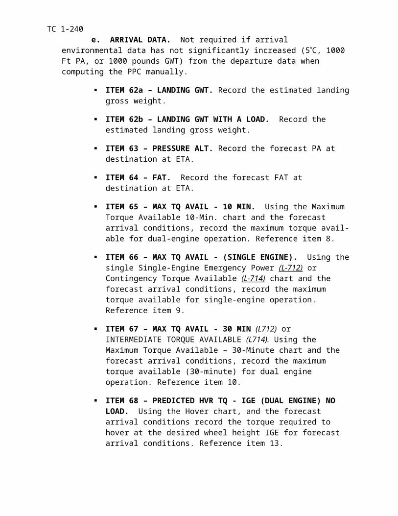
TC 1-240(2) Flight control closet. Check for leaks, extended jam indicators, loose
hardware, and soundproofing security.
(3) Heater compartment. Check for component condition, leaks, and if used, proper heater operation.
(4) Avionics compartment. Check for proper cooling fan operation and com-ponent and soundproofing security.
(5) Transformer-rectifiers. Check air intakes for obstruction. The crew member will visually check behind the seat and the soundproofing for ob-structions.
(6) Passengers and individual equipment.
Passengers. Ensure passengers are seated with seatbelt secure. Monitor passengers for symptoms of airsickness.
Individual equipment. All individual equipment not secured to a per-son or held in the hands will be secured. Equipment will not be stored/secured under or behind seats that are occupied.
(7) Area Outside Aircraft. Check both sides; check fuel cells, engine area, and aft pylon area for leaks, damage or loose cowlings.
(8) Internal cargo. Check for proper security and condition during flight. Ensure equipment boxes, tool boxes, etc. are secured during flight
Cargo containing fuel. (Vehicles, internal tanks (ERFS), etc). Check for fumes or leaks during flight. Inform the pilot immediately if fuel is leaking inside the cabin area or if fuel fumes exist.
(9) Main formers in cabin roof. Check for unusual vibration.
(10) No.1 and No. 2 engines. Visually check for leaks.
(11) Combining transmission area. Check for leaks and, unusual vibration.
(12) Engine mount and drive shaft areas. Check for unusual vibrations.
(13) Maintenance panel. Check for system malfunction.
Hydraulic pressures. Check the flight control and utility hydraulic pressure gauges for normal pressure. Ensure there is no more than +/- 50 psi fluctuation in any hydraulic gauge
Flight pressure. Normal pressure between 2500 to 3200 psi.
Utility pressure. Normal pressure between 2500 to 3500 psi.
Hydraulic temperatures. Check the flight control and utility hy-draulic temperature gauges for normal temperature.
Flight control and utility hydraulic temperatures are in the caution range between 95 to 120 degrees Celsius.
Maximum temperature for all systems is 120 degrees Celsius.
Latch indicators. Check for tripped (black and white) indications.
NOTE: The only latch indicators that a RESET can be attempted are the debris screen latches.
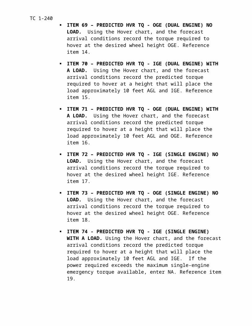
TC 1-240Warning lights. Ensure warning lights are not illuminated. Press-to-
test during cruise check to ensure the bulbs have not burned out.
Fluid levels. Ensure the fluid levels in all three systems remain con-stant.
NOTE: The aircraft hydraulic systems may be serviced in flight.
(14) Aft sync shaft bearing and mount. Check for vibrations and signs of overheating.
(15) Ramp area. Check for leaks, chafed lines, extended filter buttons, accu-mulator pressures, shorted or grounded wires and security of aft transmission access doors.
DESCRIPTION:
1. Crew actions.
a. Either RCM will call for the cruise check after takeoff or when the aircraft en-ters the mission profile.
b. The NCM will check the ramp and cabin area during the initial cruise check when called for by either RCM and every 30 minutes thereafter and as the mission allows.
2. Procedures.
a. After either RCM has called for the cruise check, the P will read the operator’s manual/CL for the appropriate checks. He will record the fuel quantity and the time. The P will obtain the rate of consumption from the fuel flow indicators and will compute and record the burnout and reserve entry time. He will determine if sufficient fuel is available to complete the mission with the required reserve and will check individual fuel tanks for the current fuel level.
b. At least every 30 minutes, the P will monitor the fuel quantity, consumption rate and verify system operation. If the fuel quantity or flow indicates a deviation from the initial check, he will repeat the initial check to determine if the fuel quantity is adequate for the mission. The P also will check individual fuel tanks to ensure that the system is operat-ing normally and determine if the fuel quantity in the auxiliary fuel tanks is decreasing nor-mally.
NOTE: Verify ability to transfer fuel from internal to external tanks before using internal tank fuel quantities in fuel reserve/burnout computations
c. The NCM(s) will check the ramp and cabin area and notify the pilots of any dis-crepancies as they are found. If no discrepancies are found, announce “Ramp and cabin check complete, all systems normal”.
NOTE 1. The clear visor provides eye protection while not degrading the crew member’s ability to see inside the aircraft. Issued sunglasses or dark visors may be worn for surveillance outside the aircraft.
NOTE 2. When two or more NCMs are assigned to the flight, the FE will outline their specific duties during the mission briefing. The ramp and cabin checks may be divided between the NCMs
NIGHT OR NVG CONSIDERATIONS: If performing ramp and cabin checks during the hours of darkness, a flashlight with an unfiltered lens will be used to supplement available light-ing. Hydraulic leaks, oil leaks, and other defects are difficult to see using a flashlight with a col-
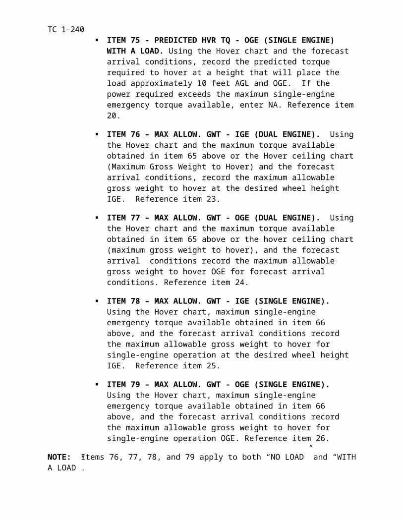
TC 1-240ored lens. NCMs must use caution while performing ramp checks with the white lights when the NVG curtain is not in use. When wearing NVGs, flip the goggles up and slide the clear visor down. When finished, slide the clear visor up, flip the goggles down, and inform pilots the status of the ramp and cabin check.
TRAINING AND EVALUATION REQUIREMENTS:
1. Training. Training will be conducted at the aircraft or in the simulator.
2. Evaluation. Evaluation will be conducted at the aircraft.
REFERENCES: Appropriate common references:
AR 95-1TC 1-204 TM 1-1520-240-10/CLUnit SOP

TC 1-240TASK 1044
Navigate by pilotage and dead reckoning
CONDITIONS: In a CH-47 helicopter or a CH-47FS and given the appropriate maps, plotter, and flight computer.
STANDARDS: Appropriate common standards plus these additions/modifications:
1. Maintain orientation within 500 meters.
2. Arrive at check points/destination at ETA ±3 minutes.
DESCRIPTION:
1. Crew actions.
a. The P* will focus primarily outside the aircraft and respond to navigation in-structions given by the P. The P* will acknowledge commands issued by the P for the head-ing, altitude, and airspeed changes necessary to navigate the desired course. The P* will an-nounce significant surface features to assist in navigation.
b. The P will direct the P* to change aircraft heading, altitude, and airspeed as ap-propriate to navigate the desired course. The P will use rally terms, specific headings, rela-tive bearings, or key terrain features to accomplish this task. He will announce all plotted wires before approaching their location when the aircraft’s altitude makes the wires a haz-ard. The P will monitor aircraft instruments and both the P and NCM will assist in clearing the aircraft while providing adequate warning to avoid traffic and obstacles. The P and NCM will announce when their attention is focused inside the aircraft and again when atten-tion is reestablished outside.
2. Procedures.
a. Both pilotage and dead reckoning will be used to maintain the position of the aircraft along the planned route. Planned headings will be adjusted as necessary to compen-sate for the effects of the wind.
b. Perform a ground speed check as soon as possible by computing the actual time required to fly a known distance. Adjust estimated times for subsequent legs of the flight route using actual ground speed. Compare planned ground speed with actual ground speed and adjust airspeed as required to arrive at each control point at its original ETA.
NIGHT OR NVG CONSIDERATIONS: More detailed flight planning is required when the flight is conducted at night. Interior cockpit lighting should be considered when selecting colors for preparing navigational aids such as maps and kneeboard notes.
TRAINING AND EVALUATION REQUIREMENTS:
1. Training. Training may be conducted in the aircraft or the simulator.
2. Evaluation. Evaluations will be conducted in the aircraft.
REFERENCES: Appropriate common references.
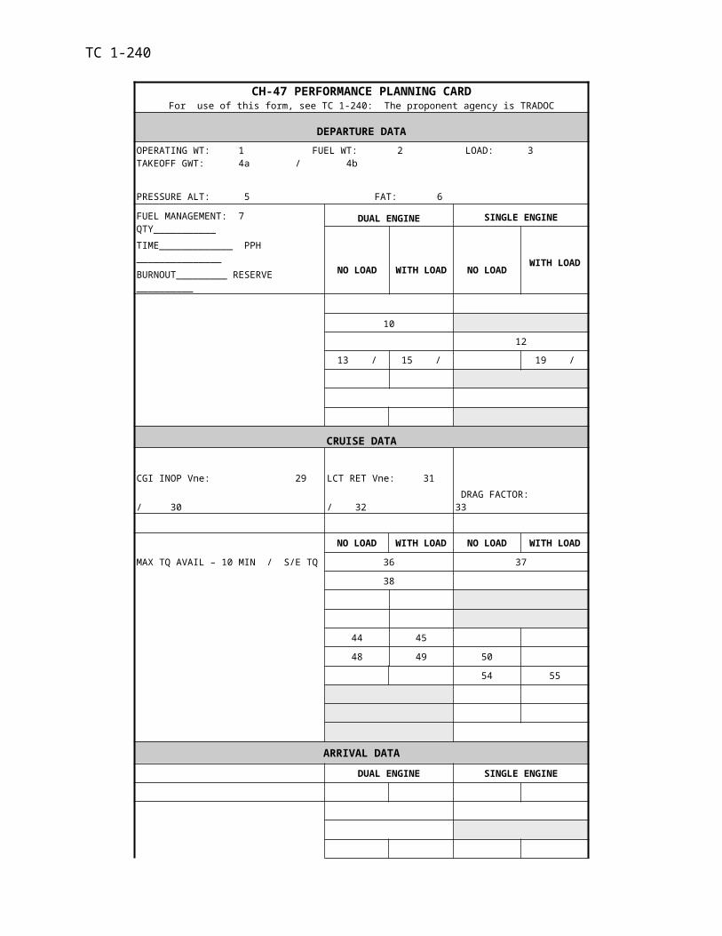
TC 1-240TASK 1046
Perform electronically aided navigation
CONDITIONS: In a CH-47 helicopter or a CH-47 FS with an electronically aided navigational system installed and operational.
STANDARDS: Appropriate common standards plus these additions/modifications:
1. Operate the installed electronically aided navigational system per the appropriate TM or manufacturer’s Operating Manual.
2. Determine the position of the aircraft along the route of flight within 200 meters.
3. Arrive at check points/destination at ETA ±2 minutes.
4. Use the HSI mode select panel per TM 1-1520-240-10 if coupled with an electronically aided navigational system.
DESCRIPTION:
1. Crew actions.
a. The P* will focus primarily outside the aircraft and respond to navigational in-structions or cues given by the P. The P* will acknowledge commands issued by the P for the heading, altitude, and airspeed changes necessary to navigate the desired course. The P* will announce significant terrain features to assist in navigation.
b. The P will be the primary operator of the electronic-aided navigation system. He will direct the P* to change aircraft heading, altitude, and airspeed as appropriate to nav-igate the desired course. The P will use rally terms, specific headings, relative bearings, or key terrain features to accomplish this task. He will announce all plotted wires before ap-proaching their location when the aircraft’s altitude makes the wires a hazard. The P will monitor aircraft instruments and both the P and NCM will assist in clearing the aircraft while providing adequate warning to avoid traffic and obstacles.
NOTE: Only the P will perform in-flight time/labor intensive NAV programming duties; for ex-ample, building routes.
2. Procedures. Perform the turn-on, test, and programming procedures per the appropriate technical manual. If the electronically aided navigational system is coupled, the selected course may be flown using the HSI mode select panel. The proper updating and shutdown procedures will be performed per the appropriate TM or manufacturer’s operator’s manual.
TRAINING AND EVALUATION REQUIREMENTS:
1. Training. Training may be conducted in the aircraft or the simulator.
2. Evaluation. Evaluations will be conducted in the aircraft.
REFERENCES: Appropriate common references plus the manufacturer’s Operating Manual if required.

TC 1-240TASK 1052
Perform VMC flight maneuvers
CONDITIONS: In a CH-47 helicopter or a CH-47FS.
STANDARDS: Appropriate common standards plus these additions/modifications:
1. Turns.
a. Clear the aircraft.
b. Maintain aircraft in trim.
c. Maintain selected airspeed + 10 knots.
d. Maintain altitude + 100 feet.
e. Maintain selected bank angle + 10 degrees.
f. Roll out on desired heading + 10 degrees.
2. Climbs and descents.
a. Clear the aircraft.
b. Maintain aircraft in trim.
c. Maintain selected airspeed + 10 knots.
d. Maintain rate of climb or descent + 100 FPM.
e. Maintain desired heading + 10 degrees.
3. Straight and level flight.
a. Maintain aircraft in trim.
b. Maintain selected airspeed + 10 knots.
c. Maintain altitude + 100 feet.
d. Maintain desired heading + 10 degrees
4. Traffic pattern flight. Enter, operate in and depart a traffic pattern.
DESCRIPTION:
1. Crew actions.
a. The P* will remain focused primarily outside the aircraft. He will announce and clear each turn, climb, and descent.
b. The P and NCM will assist in clearing the aircraft and will provide adequate warn-ing of traffic and obstacles. They will announce when their attention is focused inside the air-craft and again when attention is reestablished outside.
2. Procedures. The P* will adjust cyclic as required to maintain the desired airspeed, course, ground track, or heading as appropriate. He will adjust the thrust lever as required to maintain the desired climb/descent rate or altitude and maintain aircraft in trim with the pedals. Perform traffic pattern operations per ATC directives, AIM, local SOP, and FM 1-203.
a. VMC climb. The P* will raise the thrust lever to initiate climb. He will adjust pedals to maintain aircraft in trim. The P* will lower the thrust lever to stop climb at desired altitude.
TC 1-240b. VMC climbing turns. The P* will raise the thrust lever to initiate climb. He
will adjust pedals to maintain aircraft in trim, and apply cyclic in the desired direction of turn. The P* will adjust the cyclic as required to stop turn on heading, and lower the thrust lever to stop climb at desired altitude.
c. VMC straight-and-level flight. The P* will adjust the thrust lever to maintain altitude. He will adjust pedals to maintain aircraft in trim. The P* will maintain airspeed and heading.
d. VMC level turns. The P* will apply cyclic in the desired direction of turn. He will adjust the thrust lever to maintain altitude, and adjust pedals to maintain aircraft in trim. The P* will apply cyclic opposite the direction of turn to stop the turn on the desired head-ing.
e. VMC descents. The P* will lower the thrust lever to initiate the descent. He will adjust pedals to maintain aircraft in trim. The P* will raise the thrust lever to stop rate of descent at the desired altitude.
f. VMC descending turns. The P* will lower the thrust lever to initiate descent. He will adjust pedals to maintain aircraft in trim, and apply cyclic in the desired direction of turn. The P* will adjust cyclic as required to stop turn at the desired heading. He will raise the thrust lever to stop the descent at desired altitude.
g. Traffic pattern flight.
(1) The P* will maneuver the aircraft into position to enter the downwind leg midfield at a 45-degree angle (or according to local procedures), at traffic pattern altitude, and at the desired airspeed. (A straight-in or base-leg entry may be used if approved by ATC.) On downwind, the P will complete the before-landing check. Prior to turning base, the P* will lower the thrust lever and adjust airspeed as required and initiate a descent. If performing a straight-in or a base-leg entry, the P* will reduce airspeed at a point to facilitate the approach. The P* will turn base and final leg, as appropriate, to maintain the desired ground track. The P* will perform the desired approach. The P* will announce and each turn in the pattern and the type of ap-proach planned. The P and NCM will assist in clearing the aircraft throughout each turn in the traffic pattern.
(2) For a closed traffic pattern after takeoff, the P* will climb straight ahead at climb airspeed to the appropriate altitude, turn to crosswind, and continue the climb. The P* will initiate the turn to downwind as required to maintain the desired ground track. He will adjust the thrust lever and cyclic as required to maintain traffic pattern altitude and airspeed.
h. Before-landing check.
(1) The P will perform the before-landing check prior to turning base.
(2) The P will call out the before-landing check and announce when it is com-pleted.
NIGHT OR NVG CONSIDERATIONS:
1. The P* will focus primarily outside the aircraft and should concentrate on obstacle avoid-ance and aircraft control. The P will make all internal cockpit checks.
2. For NVG training in the traffic pattern, the recommended maximum airspeed is 100 KIAS and the recommended maximum bank angle is 30°.

TC 1-240TRAINING CONSIDERATIONS: For traffic pattern training, the recommended airspeed is 70 KIAS and a 500 FPM rate climb/descent on crosswind and base legs and 100 KIAS on the downwind leg.
TRAINING AND EVALUATION REQUIREMENTS:
1. Training. Training may be conducted in the aircraft or simulator.
2. Evaluation. Evaluation will be conducted in the aircraft.
REFERENCES: Appropriate common references.
TC 1-240TASK 1058
Perform VMC approach
CAUTION
To prevent droop-stop pounding, do not exceed ground control limitations after all landing gear contact the ground.
CONDITIONS: In a CH-47 helicopter or a CH-47FS.
STANDARDS: Appropriate common standards plus these additions/modifications:
1. Maintain a constant approach angle clear of obstacles to desired point of termination (hover) or touchdown (surface).
2. Maintain rate of closure appropriate for the conditions.
3. Maintain ground track alignment with the landing direction, as appropriate.
4. Align aircraft with landing direction below 50 feet or as appropriate for transition from terrain flight.
5. Perform a smooth and controlled termination to a hover or touchdown to the surface.
DESCRIPTION:
1. Crew actions.
a. The P* will select a suitable landing area (analyze suitability, barriers, winds, approach path, touchdown point, and takeoff direction). The P* will focus primarily outside the aircraft to provide obstacle clearance throughout the maneuver. He will announce when he begins the approach and whether the approach will terminate to a hover or to the surface. The P* also will announce the intended point of landing and any deviation from the ap-proach to include a go-around if required.
b. The P and NCM will confirm the suitability of the area, assist in clearing the aircraft, and provide adequate warning of traffic and obstacles. The P will acknowledge any deviation during the approach. The P will confirm that the LCTs retract during the ap-proach. The P and NCM will announce when their attention is focused inside the aircraft and again when attention is reestablished outside.
2. Procedures. Evaluate winds. Select an approach angle that allows obstacle clearance while descending to the desired point of termination. Once the termination point is sighted and the approach angle is intercepted, adjust the thrust as necessary to establish and maintain a con-stant angle. Maintain entry airspeed until the rate of closure appears to be increasing. Above 50-feet AGL, maintain ground track alignment and the aircraft in trim. Below 50-feet AGL, align the aircraft with the landing direction. Progressively decrease the rate of descent and rate of clo-sure until reaching the termination point (hover, touchdown), or until a decision is made to per-form a go-around.
a. To a hover. The approach to a hover may terminate with a full stop over the planned termination point, or continue movement to transition to hovering flight. Progres-sively decrease the rate of descent and rate of closure until an appropriate hover is estab-lished over the intended termination point.
TC 1-240b. To the surface. The decision to terminate to the surface with zero speed or
with forward movement will depend on the aircraft's loading and/or environmental condi-tions. Touchdown with minimum lateral movement. After surface contact, ensure that the aircraft remains stable until all movement stops. Smoothly lower the thrust-lever to the full down position and neutralize the pedals and cyclic. Apply brakes if required.
c. Go-around. The P* should perform a go-around if a successful landing is doubtful or if visual reference with the intended termination point is lost. Once climb is es-tablished, reassess the situation and develop a new course of action.
NOTE 1. Performing this maneuver in certain environments may require hover OGE power. Evaluate each situation for power required versus power available.
NOTE 2. A wind evaluation should be performed. Techniques for evaluating wind conditions are found in FM 1-202, Environmental Flight.
NOTE 3. Steep approaches can place the aircraft in potential settling-with-power conditions.
NIGHT OR NVG CONSIDERATIONS:
1. Altitude, apparent ground speed, and rate of closure are difficult to estimate at night. The rate of descent during the final 100 feet should be slightly less than during the day to avoid abrupt attitude changes at low altitudes. After establishing the descent during unaided flights, slightly reduce airspeed until apparent ground speed and rate of closure appear to be increasing. Progressively decrease the rate of decent and forward speed until termination of the maneuver.
2. Surrounding terrain or vegetation may decrease contrast and cause degraded depth percep-tion during the approach. Before descending below obstacles, determine the need for artificial lighting.
3. Use proper scanning techniques to avoid spatial disorientation.
4. When performing operations during unaided night flight, ensure that the searchlight or landing light (white light) is in the desired position. Use of the white light may impair night vi-sion, therefore, exercise added caution if resuming flight before reaching full dark adaptation.
SNOW/SAND/DUST CONSIDERATIONS:
1. Termination to a point OGE. This approach requires OGE power and may be used for some snow/sand/dust landings. Make the approach to an OGE hover over the intended landing point. Slowly lower the thrust and allow the aircraft to descend. The rate of descent will be de-termined by the rate in which the snow/sand/dust is blown from the intended landing point. Re-main above the snow/sand/dust cloud until it dissipates and visual references can be seen for touch down. After ground contact, lower the thrust-lever to the full down position and neutralize the flight controls.
2. Termination to the surface with forward speed. This termination may be made to an improved landing surface or suitable area with minimal ground references. Once the appropriate approach angle is intercepted, adjust the thrust-lever as necessary to establish and maintain the angle. As the apparent rate of closure appears to increase, progressively decrease the rate of de-scent and rate of closure to arrive at the touchdown area slightly above effective translational lift. At this point, maintain the minimum rate of closure that ensures that the snow/sand/dust cloud remains behind the pilot's station. When the wheels or skis contact the ground, smoothly lower the thrust-lever and allow the aircraft to settle. Maintain landing attitude at touch-down to pre-vent burying the wheels or skis.
TC 1-2403. Termination to the surface with no forward speed. This termination should be made to
landing areas where slopes, obstacles, or unfamiliar terrain, preclude a landing with forward speed. It is not recommended when new or powder snow or fine dust is present because white/brown out conditions will occur. The termination is made directly to a reference point on the ground with no forward speed. After ground contact, smoothly lower the thrust-lever to the full down position and neutralize the flight controls.
NOTE 1. Brakes set or released may be determined by the type of surface, hard or soft, during the recon.
rrrrrrrrrrrrrrrrrrrrrrrrrrrrrrrrrrrrrrrrrrrrrrrrrrrrrrrrrrrrrrrrrrrrrrrrrrrrrrrrrrrrrrrrrrrrrrrrrrrrrrrrrrrrrrrrrrrrrrrrrrrrrrrrrrrrrrrrrrrrrrrrrrrrrrrrrrrrrrrrrrrrrrrrrrrrrrrrrrrrrrrrrrrrrrrrrrrrrrrrrrrrrrrrrrrrrrrrrrrrrrrrrrrrrrrrrrrrrrrrrrrrrrrrrrrrrrrrrrrrrrrrrrrrrrrrrrrrrrrrrrrrrrrrrrrrrrrrrrrrrrrrrrrrrrrrrrrrrrrrrrrrrrrrrrrrrrrrrrrrrrrrrrrrrrrrrrrrrrrrrrrrrrrrrrrrrrrrrrrrrrrrrrrrrrrrrrrrrrrrrrrrrrrrrrrrrrrrrrrrrrrrrrrrrrrrrrrrrrrrrrrrrrrrrrrrrrrrrrrrrrrrrrrrrrrrrrrrrrrrrrrrrrrrrrrrrrrrrrrrrrrrrrrrrrrrrrrrrrrrrrrrrrrrrrrrrrrrrrrrrrrrrrrrrrrrrrrrrrrrrrrrrrrrrrrrrrrrrrrrrrrrrrrrrrrrrrrrrrrrrrrrrrrrrrrrrrrrrrrrrrrrrrrrrrrrrrrrrrrrrrrrrrrrrrrrrrrrrrrrrrrrrrrrrrrrrrrrrrrrrrrrrrrrrrrrrrrrrrrrrrrrrrrrrrrrrrrrrrrrrrrrrrrrrrrrrrrrrrrrrrrrrrrrrrrrrrrrrrrrrrrrrrrrrrrrrrrrrrrrrrrrrrrrrrrrrrrrrrrrrrrrrrrrrrrrrrrrrrrrrrrrrrrrrrrrrrrrrrrrrrrrrrrrrrrrrrrrrrrrrrrrrrrrrrrrrrrrrrrrrrrrrrrrrrrrrrrrrrrrrrrrrrrrrrrrrrrrrrrrrrrrrrrrrrrrrrrrrrrrrrrrrrrrrrrrrrrrrrrrrrrrrrrrrrrrrrrrrrrrrrrrrrrrrrrrrrrrrrrrrrrrrrrrrrrrrrrrrrrrrrrrrrrrrrrrrrrrrrrrrrrrrrrrrrrrrrrrrrrrrrrrrrrrrrrrrrrrrrrrrrrrrrrrrrrrrrrrrrrrrrrrrrrrrrrrrrrrrrrrrrrrrrrrrrrrrrrrrrrrrrrrrrrrrrrrrrrrrrrrrrrrrrrrrrrrrrrrrrrrrrrrrrrrrrrrrrrrrrrrrrrrrrrrrrrrrrrrrrrrrrrrrrrrrrrrrrrrrrrrrrrrrrrrrrrrrrrrrrrrrrrrrrrrrrrrrrrrrrrrrrrrrrrrrrrrrrrrrrrrrrrrrrrrrrrrrrrrrrrrrrrrrrrrrrrrrrrrrrrrrrrrrrrrrrrrrrrrrrrrrrrrrrrrrrrrrrrrrrrrrrrrrrrrrrrrrrrrrrrrrrrrrrrrrrrrrrrrrrrrrrrrrrrrrrrrrrrrrrrrrrrrrrrrrrrrrrrrrrrrrrrrrrrrrrrrrrrrrrrrrrrrrrrrrrrrrrrrrrrrrrrrrrrrrrrrrrrrrrrrrrrrrrrrrrrrrrrrrrrrrrrrrrrrrrrrrrrrrrrrrrrrrrrrrrrrrrrrrrrrrrrrrrrrrrrrrrrrrrrrrrrrrrrrrrrrrrrrrrrrrrrrrrrrrrrrrrrrrrrrrrrrrrrrrrrrrrrrrrrrrrrrrrrrrrrrrrrrrrrrrrrrrrrrrrrrrrrrrrrrrrrrrrrrrrrrrrrrrrrrrrrrrrrrrrrrrrrrrrrrrrrrrrrrrrrrrrrrrrrrrrrrrrrrrrrrrrrrrrrrrrrrrrrrrrrrrrrrrrrrrrrrrrrrrrrrrrrrrrrrrrrrrrrrrrrrrrrrrrrrrrrrrrrrrrrrrrrrrrrrrrrrrrrrrrrrrrrrrrrrrrrrrrrrrrrrrrrrrrrrrrrrrrrrrrrrrrrrrrrrrrrrrrrrrrrrrrrrrrrrrrrrrrrrrrrrrrrrrrrrrrrrrrrrrrrrrrrrrrrrrrrrrrrrrrrrrrrrrrrrrrrrrrrrrrrrrrrrrrrrrrrrrrrrrrrrrrrrrrrrrrrrrrrrrrrrrrrrrrrrrrrrrrrrrrrrrrrrrrrrrr. Packed Surface area: Thin layer of snow or dust atop hard sub-surface with some
visible terrain elements such as rocks. Set the brakes to minimize forward roll after landing.
b. Soft Surface area: Thick layer of snow or dust with no visible sub-surface. Re-lease the brakes to minimize abrupt stop after landing and unnecessary stress on the aft land-ing gear.
NOTE 1. When landing in deep snow, the aircraft wheels/skis may settle at different rates.
NOTE 2. During sand/dust landings, all doors and windows should be closed and vent blowers turned off.
NOTE 3. OGE hovering reduces available ground references and may increase the possibility of spatial disorientation. Be prepared to transition to instruments and execute an instrument takeoff if ground reference is lost.
NOTE 4. At night, use of the landing, search, or anti-collision light may cause spatial disorientation while in blowing snow/sand/dust.
CONFINED AREA CONSIDERATIONS:
1. Prior to commencing the approach, the crew will determine and brief an escape route in case a go-around is necessary.
2. An approach to the forward one-third of the useable area will reduce the approach angle and minimize power requirements.
3. During the approach, continue to determine the suitability of the area. If possible, make the decision to go-around before descending below the barriers or going below ETL.
4. The parking brake should be set prior to landing on unimproved areas where the surface slopes. Refer to tasks 1062, perform slope operations.
5. After touching down, check aircraft stability as the thrust-lever is lowered.
MOUNTAIN/PINNACLE/RIDGELINE CONSIDERATIONS:
1. Before commencing the approach, the crew will determine and brief an escape route in case a go-around is necessary.
2. Select a shallow to steep approach angle, depending on the wind, density altitude, gross weight, and obstacles. During the approach, continue to determine the suitability of the intended landing point
3. The rate of closure may be difficult to determine until the aircraft is close to the landing point.
TC 1-2404. Reduce airspeed to slightly above effective translational lift until the rate of closure can be
determined and decide whether to continue the approach or make a go-around. If a go-around is required, it should be performed before decelerating below ETL. If the approach is continued, terminate to a hover or to the surface.
5. After touching down, check aircraft stability as the thrust-lever is lowered. See task 2125 perform pinnacle/ridgeline operations.
NOTE: To successfully operate into small areas, it may be necessary to place the nose of the aircraft over the edge of the landing area. This may cause a loss of important visual references when on final approach. All crew members must assist in providing information on aircraft position in the landing area.
MUD/MUSKEG/TUNDRA CONSIDERATIONS: Select a suitable area and terminate the ap-proach to a 10-foot hover over the intended touchdown point. Begin a vertical descent until the aircraft touches down. Check aircraft stability while lowering the thrust-lever. If the area is suit-able, lower the thrust-lever to the full down position, and neutralize the cyclic and pedals.
TRAINING AND EVALUATION REQUIREMENTS:
1. Training. Training may be conducted in the aircraft or simulator.
2. Evaluation. The evaluation will be conducted in the aircraft.
REFERENCES: Appropriate common references.
TC 1-240TASK 1062
Perform slope operations
CAUTION
To prevent droop-stop pounding, do not exceed ground control limitations after all landing gear contact the ground.
CONDITIONS: In a CH-47 helicopter with aircraft cleared.
STANDARDS: Appropriate common standards plus these additions/modifications:
1. Rated :
a. Select a suitable landing area.
b. Set the parking brakes before landing.
c. Maintain heading ±5 degrees.
d. Maintain minimum drift prior to touch down and then no drift allowed after wheel contact.
2. Nonrated:
a. Confirm suitable landing area.
b. Clear the aircraft.
DESCRIPTION:
1. Crew actions.
a. The P* will announce his intent to perform a slope operation and will establish the helicopter over the slope. He will set the brakes, requesting assistance if needed. The P* will remain within ground control limitations. He will announce his intended landing area and any deviation from the intended maneuver. The P* will note the aircraft attitude at a hover, prior to starting descent to land on the slope.
b. All crew members will clear the aircraft and provide warning of obstacles, ex-cessive drift, or excessive attitude changes.
c. The NCM will assume a position where he can observe the slope operation. He will clear his sector while checking that the rotor blades are clear of obstacles and the ground. The NCM will call out wheel height from 10 feet to the ground in 1-foot incre-ments. He will advise the P* when all landing gear are on the ground and the aircraft is sta-ble.
2. Procedures.
a. Upslope landings. With the aircraft heading upslope, the P* will lower the thrust-lever until the forward landing gear contacts the ground. He will maintain heading with the pedals and adjust cyclic as necessary to maintain the position of the aircraft. The P* will continue to lower the thrust-lever until the aft landing gear contacts the ground. When all landing gear are on the ground, he will smoothly lower the thrust-lever to ground
TC 1-240detent. The P* will then neutralize the controls while checking the stability of the aircraft. He will perform the takeoff from the upslope in the reverse sequence.
b. Downslope landings. With the aircraft heading downslope, the P* will lower the thrust-lever until the aft landing gear contacts the ground. He will adjust pitch attitude to maintain a stabilized position on the slope by coordinating thrust reduction with aft cyclic movement. This may result in a slightly higher pitch attitude when the LCTs program to ground detent. The P* will maintain heading with the pedals. He will smoothly and contin-uously lower the thrust-lever until the forward landing gear contacts the ground. If the air-craft slides down the slope, the P* will return to a hover and reposition. When all landing gear are on the ground, he will smoothly lower the thrust-lever to ground detent The P* will then neutralize the controls while checking the stability of the aircraft. He will perform the takeoff from the downslope in the reverse sequence.
NOTE: The LCT will program to ground position as soon as the aft landing gear contacts the ground and the landing gear proximity switches engage. This may cause the aircraft to accelerate forward. To prevent this acceleration, the crew has two options. The P may place the AFCS cyclic trim switch to MANUAL and land with the LCT actuators in the retract position or extend the actuators to GND before conducting slope operations. After landing with the LCTs in the retract position, ensure the LCTs are placed to the ground position. After departing the slope, the P will return the AFCS cyclic trim switch to AUTO.
c. Cross-slope landings. With the aircraft heading cross slope, the P* will lower the thrust-lever until the upslope aft landing gear contacts the ground. He will maintain heading with the cyclic and pedals as required. The P* will maintain pitch attitude by coor-dinating thrust-lever reduction with aft cyclic movement. This will normally place the downslope aft landing gear in contact with the ground. The P* will coordinate the cyclic and pedals as necessary. He will continue to lower the thrust-lever until the forward landing gear is on the ground. The P* will smoothly lower the thrust-lever to ground detent. The P* will then neutralize the controls while checking the stability of the aircraft. He will perform the takeoff from the cross slope in the reverse sequence.
NOTE 1. Before conducting slope operations, RCMs must understand droop-stop charac-teristics.
NOTE 2. If at any time successful completion of the landing is doubtful, the P* must abort the maneuver.
NOTE 3. If the slope landing cannot be conducted without droop stop pounding, reposition the aircraft.
NIGHT OR NVG CONSIDERATIONS:
1. When conducting slope operations, select reference points to determine slope an-gles.
2. When performing operations during unaided night flight, ensure that the searchlight is in the desired position. Use of the white light may impair night vision, therefore, exercise added caution if resuming flight before reaching full dark adaptation.
TRAINING AND EVALUATION REQUIREMENTS:
1. Training. Training will be conducted in the aircraft.
2. Evaluation. Evaluation will be conducted in the aircraft.
REFERENCES: Appropriate common references.
TC 1-240
TASK 1063Perform external load operations
WARNING:
At no time will the push to talk button on the hoist/winch control grip be used during exter-nal load operations. Inadvertent hook release could occur if NCM does not visually locate release button prior to releasing load.
CAUTION
A static electricity discharge wand will be utilized IAW FM 10-450-1.
CONDITIONS: In a CH-47 helicopter with operational cargo hook(s), external load, completed DA Form 7382-R, or training load IAW FM 10-450-3 or in a CH-47FS.
NOTE: A qualified Sling Load Inspector prior to sling load operations will inspect all non-training external loads. Certification must be recorded on a Sling Load Inspection Record DA Form 7382-R and copies distributed IAW FM 10-450-3.
STANDARDS: Appropriate common standards plus these additions/modifications:
1. Rated.
a. Before hookup. Verify DA Form 7382-R is complete and on file and that, the aircraft will remain within gross weight and CG limitations.
b. Hookup and hover.
(1) Ensure that the aircraft remains clear of the load and any obstacles.
(2) Perform a vertical descent/ascent with the load to a load height of 10 feet ±3 feet or appropriate for the conditions.
(3) Determine power sufficient to continue the maneuver.
c. Takeoff.
(1) Maintain aircraft in trim (above 100-feet AGL).
(2) The P will call out load height from 10’ in 5-foot increments up to 25 feet; 25-foot increments up to a load height of 100 feet.
d. Approach and load release.
(1) Maintain a constant approach angle to ensure the load safely clears obsta-cles and terminate over the intended point of landing.
(2) Perform a vertical descent with the load to the desired touchdown point ±5 feet.
(3) The P will call the load height on approach 100’ to 25’ in 25 foot incre-ments; 25’ to 10’ in 5 foot increments.

TC 1-2402. Nonrated.
a. The NCM will ensure that the aircraft is prepared for sling load operations.
b. Ensure that all sling equipment is inspected and secured in the aircraft.
c. Provide aircraft guidance for hook up and release using no more than two directions at a time.
d. Clear the aircraft and sling load during the operation.
e. Confirm load is hooked and secure.
f. Ensure load is free of entanglements.
g. Continue to monitor load for oscillation.
h. The NCM will call the load height from 10’ to the ground and from the ground to 10’ in 1 foot increments.
i. Monitor and call the load height during terrain flight at altitudes of 200’ AHO and below.
DESCRIPTION:
1. Crew actions.
a. The PC will conduct a thorough crew briefing and ensure all crew members are familiar with external load operations, emergency, and communication procedures. Figure 4-5 is an example of an external load briefing checklist. He will ensure that DD Form 7382-R has been completed. He will determine the direction of takeoff by analyzing the tactical situation, the wind, the long axis of the takeoff area, and the lowest obstacles and will con-firm that required power is available by comparing the information from the PPC to the hover power check.
b. The P* will remain focused outside the aircraft throughout the maneuver. He will monitor altitude and avoid obstacles.
c. The P will monitor the cockpit instruments and assist the P* in clearing the air-craft. He will set cargo hook switches, as required, and should make all radio calls. When directed by the P*, the P will "arm" the cargo hook.
d. The P and NCM will assist in clearing the aircraft and will provide adequate warning of obstacles.
e. The NCM will remain primarily focused on the load. The NCM may place the radio switches on the ICS OFF, the cargo hook switch on the hoist operator's panel is ARMED, and the hoist operator’s grip is secured and within easy reach. He will guide the P* during the load pickup, advise of the load condition in flight, and direct the P* when set-ting down the load.
f. The NCM will attach his restraining harness to a 5,000 lb. tie-down ring and as-sume a position at the right aft corner of the rescue hatch
2. Procedures. Figure 4-4 shows examples of words and phrases that may be used for ex-ternal load operations.
3. Hookup and hover. P set cargo hook control switch in the “ALL” position, place the cargo hook switch in the arm position. The P may place the radio switches on the P* ICS OFF as directed by P*. The P* will announce when the load is under the nose of the aircraft or
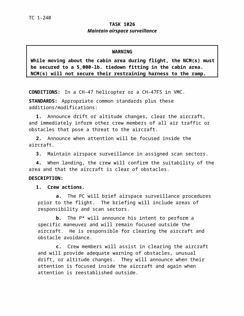
TC 1-240when he loses sight of the load. If the NCM will use “HOT MIKE” he will inform the P* that he will be going on HOT MIKE. Follow hand signals from the signalman and commands from the NCM to hover over the load. Remain vertically clear of and centered over the load. When the load is hooked, the NCM will inform the P* that the load is hooked, remove slack from the sling and ascend vertically to a stabilized load height of 10 feet. If the NCM is using “HOT MIKE”, he will inform the P* that he is going Off HOT MIKE. If a ground crew is used for the hook-up, the NCM will advise the P* when and in what direction the crew cleared the load and the air-craft. The NCM will monitor the load rigging and advise the P* when the slings are tight. Dur-ing the load hookup and after the slings are tight, the P should refer to the radar altimeter for ac-tual aircraft height AGL. He should then round up the height to the nearest 5 feet and add 10 feet for the appropriate hover height. The NCM will callout load height in 1-foot increments un-til the load is 10 feet off the ground. When the load is stable and the rigging appears safe, the NCM will announce that the load is cleared for flight. Ensure aircraft limitations are not ex-ceeded.
a. Takeoff. The P* will maintain a 10-foot load height until the P completes a hover power check and a before-take-off check. Before take-off, the P* will ensure that the load is cleared for flight by the NCM. The P* will make smooth control inputs to initiate the take-off and establish a constant angle of climb that will permit safe obstacle clearance. During take-off, the P will call out load height above the ground or obstacles in 5-foot incre-ments up to 25 feet. He will then call out load height in 25-foot increments up to a load height of 100 feet. When above 100 feet AGL or when clear of obstacles, adjust attitude and power as required to establish the desired rate of climb and airspeed. During the accel-eration, he will avoid unnecessary nose-low attitudes and over controlling to reduce load os-cillation. The NCM will announce the load condition i.e. (load clear of all barriers, load is stable etc). When above 100 feet AGL or when clear of obstacles, the P* will increase air-speed slowly to determine the flight characteristics of the load. Smoothly adjust flight con-trols to prevent load oscillation. After passing though 200-feet AHO load height and best single engine airspeed, the cargo hook master switch may be placed in the OFF position. The crew will verbally acknowledge placement of the cargo hook master switch to OFF.
NOTE 1: Ensure that the cargo switch is in the ARM position when operating at altitudes below 200-feet AHO and/or below best single engine airspeed.
NOTE 2: If a load oscillation develops the primary method for arresting the oscillation is to decrease airspeed. Additional measures may include shallow turns or banks, and / or small climbs or descents, or a combination of any or all methods.
b. En route. During cruise flight, the P will place the cargo hook master switch in the OFF position, as directed in paragraph b above, and announce that the cargo hook master switch is OFF; the NCM will verbally confirm that the cargo hook master switch is OFF. The P will turn on the P*’s radio switches as required. He will advise the P* to take control of the RRPM. Maintain the desired altitude, flight path, and airspeed. Make smooth control applications to prevent load oscillation. The NCM will monitor the load for oscilla-tion/load height and advise the P* of the status of the load.
c. Approach and load release. The P may turn OFF the P*’s radio switches, as directed. The P will announce that he will control the RRPM, (L712 engines). The P* will establish and maintain an approach angle that will keep the load clear of obstacles to the de-sired point of termination. Establish a rate of closure appropriate for the conditions and the load. (A go-around should be made before descending below obstacles or decelerating be-low ETL.) Prior to passing below 200 feet AHO load height and/or below best single en-gine airspeed, place the cargo hook master switch in the ARM position. The crew will ver-
TC 1-240bally confirm placement of the cargo hook master switch to the ARM position. The P will call load height from 100 feet AGL to 25 feet AGL in 25-foot increments. The NCM will advise the P* when the load is clear of obstacles. The P will continue to call out load height in 5-foot increments down to a stabilized load height of 10 feet. The P* will terminate the approach at a stationary hover with the load 10 feet above the intended release point. The NCM will confirm that the release point is clear and direct the aircraft to the release point. The NCM will then clear the load down vertically; he will call out load height in 1-foot in-crements until the load rests completely on the ground. Continue descent to obtain slack in the slings, and then hover laterally to ensure the clevis is clear of the load before releasing the load, the NCM will advise the P* when the clevis is clear. The NCM will release the load upon confirmation from the P* or per unit SOP. The NCM will confirm that the load is released before clearing the P* to reposition from the release point.
NOTE 1. Prior to conducting an external load operation, all crew members must ensure that they are able to communicate with each other.
NOTE 2. The NCM will place his intercom switch to “HOT MIKE” when using the cargo loading pole. If two or more NCMs will be conducting crew duties, the CE may brief one of the additional crew members to place him on “HOT MIKE.
NOTE 3. The P* will not allow the external load to descend below the hover height until the CE has cleared the load to the ground.
NOTE 4. Loads will meet External Air Transportability (EAT) requirements IAW FM 10-450-3. Procedures for air transportation of hazardous material will be IAW AR 95-27.
NOTE 5. If possible, avoid flight over populated areas.
NOTE 6. Before the mission, the PC will ensure that all crew members and the hookup crew are familiar with the hand and arm signals shown in TC 1-201 and with forced landing procedures.
NIGHT OR NVG CONSIDERATIONS:
1. For unaided night flight, one landing/searchlight will be unfiltered / white-light.
2. When NVG are used, hovering with minimum drift is difficult and requires proper scanning techniques and crew coordination. If possible, an area with adequate ground contrast and reference points should be used. Visual obstacles such as shadows should be treated the same as physical obstacles.
3. The rate of descent and rate of closure should be slightly slower to avoid abrupt atti-tude changes at low altitudes.
4. The CE calling the load should wear NVGs during external load operations. He will notify the PC anytime he must “flip up” the NVGs. White lighting, i.e. flashlight or searchlight may be used as necessary to view the hooks or loads.
5. The NCM and the P will monitor the load and inform the P* if the rate of descent/airspeed is excessive or if they doubt the accuracy of the radar altimeter.
TRAINING AND EVALUATION REQUIREMENTS:
1. Training. Training will be conducted in the aircraft.
2. Evaluation. Evaluations will be conducted in the aircraft.

TC 1-240
Standard words and phrases for external load operations.“Cargo Hook Master Switch is ARMED” “Forward hook is hooked”“Load under the nose” “Aft hook is hooked”“Load in sight” “Mid-hook is hooked”“Forward” “Hookup crew clear right”“Back” “Hook up crew clear left”“Left” “Slings coming tight”“Right” “Slings tight”“Down” “Load is off the ground”“Up” “Cleared for flight”“Hold” “Load on ground”“Pole in hand” “Slack in the slings”“Clevis on pole” “Release the load”“Clevis on loading pole” “Load is released”“Hook in hand” “Clear to reposition”“Load is hooked” “Cargo Hook Master Switch is OFF”
Figure 4-4. Standard words and phrases for Sling Load Operations
TC 1-240
External load crew briefing.External Load Procedures
(1) Prior to Hookup – Determine take-off gross weight, single-engine capability, and verify GO/NO-GO and Validation Factor.
(2) Pilot NOT on the Controls - DUTIES(a) Arm the Cargo Hook Master switch.(b) Turn OFF P* radio pin switches if required.(c) ALQ-156 – STANDBY(d) M-130 or ALE-47 as required.(e) ARC 220 – STANDBY or OFF.(f) Inform P* Prior to reaching limits.(g) Perform Hover Power check and Before Take-off check.(h) Cargo Hook Master Switch:
OFF above 200’ AHO or S/E airspeed.ARMED below 200' or S/E Airspeed.
(3) Non-Rated Crew Member - DUTIES(a) NCM calling load will have radios OFF and winch/hoist con-
trol grip secured and positioned within reach.(b)Advise Load in Sight(c) Direct *Pilot over Load (No more than two directions at a
time)(d)Advise when Load is Hooked (e) Advise when Hook-up man is clear and Direction(f) Advise when Load is clear to come up(g)Advise when Slings are tight(h)Advise Load Heights IAW TC 1-216(i) Monitor Load in Flight(j) Advise Load Heights on Approach - Pilot NOT on the Flight
Controls calls Load Height from 100’ to 10’ during NVG Op-erations.
(4) Hook Authority.(a) Normal – Rests with PC, but normally is released by the NCM(b) Emergency – Rests with PC. PC will determine when the
Load will be jettisoned based on aircraft performance. The NCM at the load must jettison the load if it will endanger the crew or aircraft. Load jettisons will be announced to the aircrew.
(5) ICS Failure between Pilots and Crew (Two Challenge).(a) Before Load is Hooked/ Slack in Sling - NCM opens hook
with Normal release(b) After Slings tight/Load is Lifted - NCM with commo will
notify crew and call the load down.(c) Between pilots – Pilot with commo takes flight controls.
(6) Aircrew comments and acknowledgment of briefing.Figure 4-5. External load crew briefing
REFERENCES: Appropriate common references plus the following:
FM 21-60AR 95-27FM 10-450-3/4/5TM 10-1670-295-23&P
TC 1-240
TASK 1064Perform a roll-on landing
CONDITION: In a CH-47 helicopter or a CH-47FS with the before landing check complete.
STANDARDS: Appropriate common standards plus these additions/modifications:
1. Select a suitable landing area.
2. Maintain a constant approach angle clear of obstacles to desired point of touchdown.
3. Maintain ground track alignment with the landing direction, as appropriate.
4. Perform a smooth, controlled touchdown, at/above ETL, but below 60 knots ground speed. Touch down with a maximum of 20-degree nose high pitch attitude, aligned with the landing direction ±5 degrees.
DESCRIPTION:
1. Crew actions.
a. The P* will focus primarily outside the aircraft to clear the aircraft throughout the approach and landing. He will announce his intent to perform a roll-on landing, the in-tended point of landing, and any deviation from the approach.
b. The P will verify that the brakes are released and that the swivels are locked be-fore starting the approach. The P and NCM will confirm the suitability of the landing area and will provide adequate warning of hazards or obstacles.
2. Procedures.
a. Before starting the approach, the P will verify that the brakes are released and that the swivels are locked. When the desired approach angle is intercepted, the P* will lower the thrust-lever as required to establish the descent. The P will assist the P* as neces-sary with maintaining rotor RPM during the approach. The P* will maintain entry airspeed until reaching approximately 100 feet AGL or a point from which the obstacles can be cleared. He will then assume a progressive decelerating attitude to achieve a touchdown on the aft landing gear. The touchdown speed will be commensurate with aircraft performance and landing area conditions. The NCM will inform the P* when the aircraft is clear of all obstacles in the flight path. The P* will slip the aircraft during the deceleration to achieve runway alignment prior to touchdown. The P will check that the LCTs retract during the de-celeration. The P* will maintain the desired angle of descent with the thrust-lever. Prior to touchdown, he will adjust the thrust-lever to achieve a smooth touchdown on the aft landing gear before going below ETL.
b. After landing, the P* will maintain the landing attitude with the cyclic and thrust-lever (not to exceed 20 degrees, nose high) until forward speed is sufficiently slowed or stopped. The P* will smoothly lower the thrust-lever until the forward landing gear contacts the ground. He will then neutralize the flight controls and apply brakes as neces-sary to stop forward movement.
NIGHT OR NVG CONSIDERATIONS: Altitude, apparent ground speed, and rate of closure are difficult to estimate when making an approach to an area of limited contrast. The P* will de-termine the need for artificial lighting prior to descending below the obstacles or 100 feet.
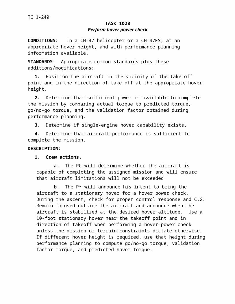
TC 1-240ROUGH/UNPREPARED SURFACE CONSIDERATIONS: Closely monitor touchdown speed when landing to a rough or unprepared surface. Consistent with the situation and aircraft capabilities, a more pronounced deceleration before touchdown coupled with stronger aerody-namic braking after touchdown may be appropriate. Note that the wheel brakes may be less ef-fective. To prevent an abrupt stop, smoothly lower the thrust-lever until the aircraft comes to a complete stop.
TRAINING AND EVALUATION REQUIREMENTS:
1. Training. Training may be conducted in the aircraft or simulator.
2. Evaluation. The evaluation will be conducted in the aircraft.
REFERENCES: Appropriate common references.
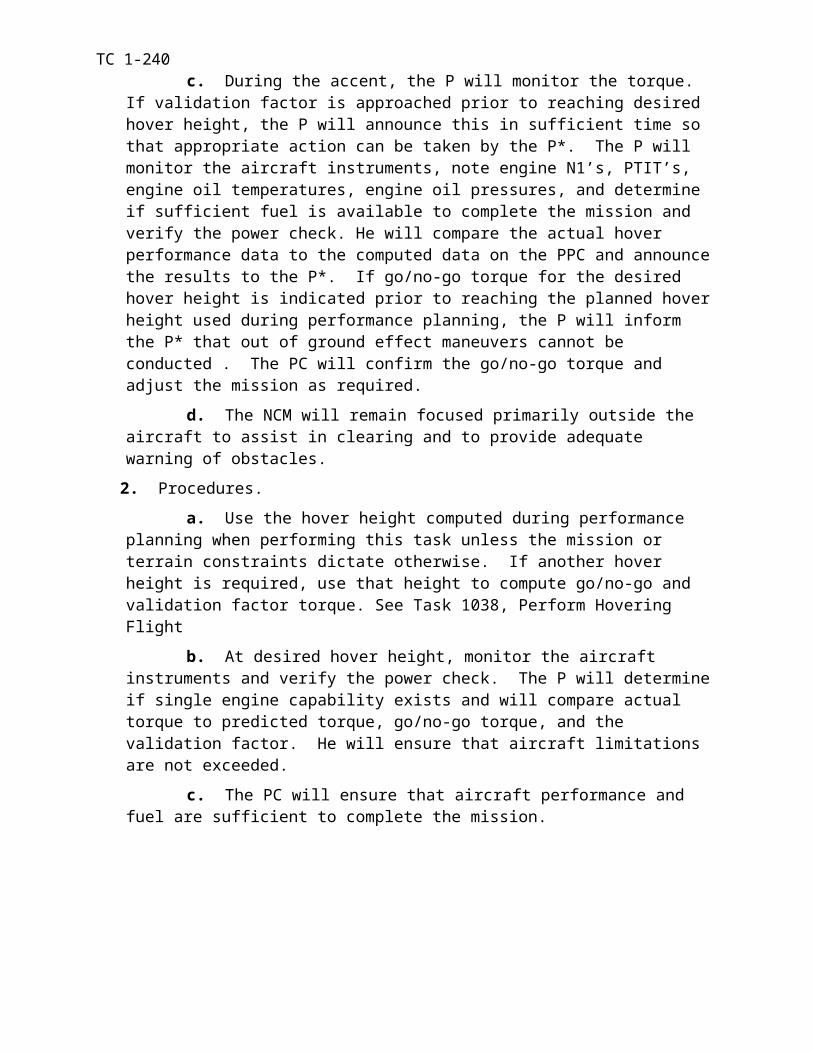
TC 1-240TASK 1070
Perform emergency procedures
CONDITIONS: In a CH-47 helicopter or in a CH-47FS with an IP; or academically and given a specific emergency condition, or the indications of a specific malfunction.
STANDARDS: Appropriate common standards plus the following additions/modifications:
1. Rated.
a. Recognize, announce, and analyze indications of an emergency. Perform or de-scribe the all immediate action emergency checks IAW TM 1-1520-240-10/CL.
b. Perform appropriate emergency procedure.
c. Confirm the suitability of the landing area.
2. Nonrated.
a. Recognize, announce, and analyze indications of an emergency. Perform or de-scribe all immediate action emergency checks IAW TM 1-1520-240-10/CL.
b. Perform appropriate emergency procedure.
c. Prepare the aircraft and passengers for an emergency landing.
d. Assist in confirming the suitability of the landing area.
e. Assist in evacuating passengers to designated assembly area.
DESCRIPTION:
1. Crew actions. Any crew member detecting an emergency will immediately announce the emergency to the other crew members.
a. The crew will perform the underlined and non-underlined steps as appropriate per the operator’s manual/CL and initiate the appropriate type of landing. During VMC, the P* will focus primarily outside the aircraft to maintain aircraft control and obstacle clear-ance. During IMC, the P* will remain focused inside the aircraft on the flight instruments to maintain aircraft control. If time permits RCMs will also lock shoulder harnesses, make a mayday call, and tune transponder to emergency as required.
b. If time permits, the P will verify all emergency checks with the operator’s man-ual/CL. He will request appropriate emergency assistance.
c. The NCM will prepare the passengers for an emergency landing, ensuring pas-senger’s seat belts are fastened and cargo is secured. During the descent, he will assist in clearing the aircraft. After landing, the NCM will assist in evacuating the passengers to the designated assembly area. If normal exits cannot be used, he will use the nearest emergency exit to expedite the evacuation. After accounting for all crew members and passengers, the NCM will assist the other crew members in any follow-on action (fire fighting, first aid, emergency signaling, or survival equipment).
2. Procedures. Analyze the emergency situation (for example, aircraft response and caution light indications). Determine the malfunction and select the appropriate emergency procedures IAW TM 1-1520-240-10/CL.
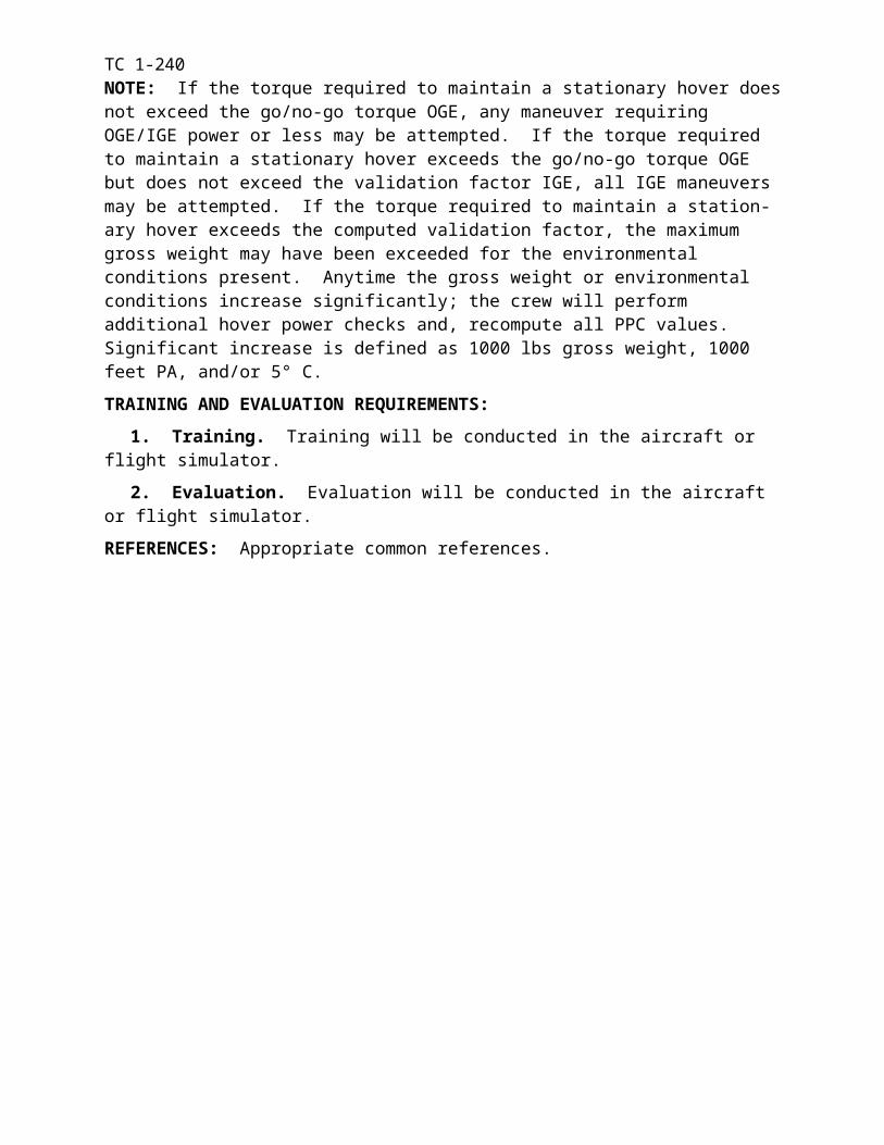
TC 1-240NOTE: Only qualified and current IP’s/SP’s may simulate emergency procedures when at one set of flight controls. Paragraph 4-1c (6) lists the emergency procedures that are prohibited from practice in the aircraft. Appendix E contains information on executing simulated emergency pro-cedures.
NIGHT OR NVG CONSIDERATIONS: Take special precautions to identify the correct switches/levers when performing emergency procedures at night or while wearing NVGs.
TRAINING AND EVALUATION REQUIREMENTS:
1. Training. Training may be conducted in the aircraft, simulator or academically.
2. Evaluation. Evaluation may be conducted in the aircraft, simulator or academically.
REFERENCES: Appropriate common references.
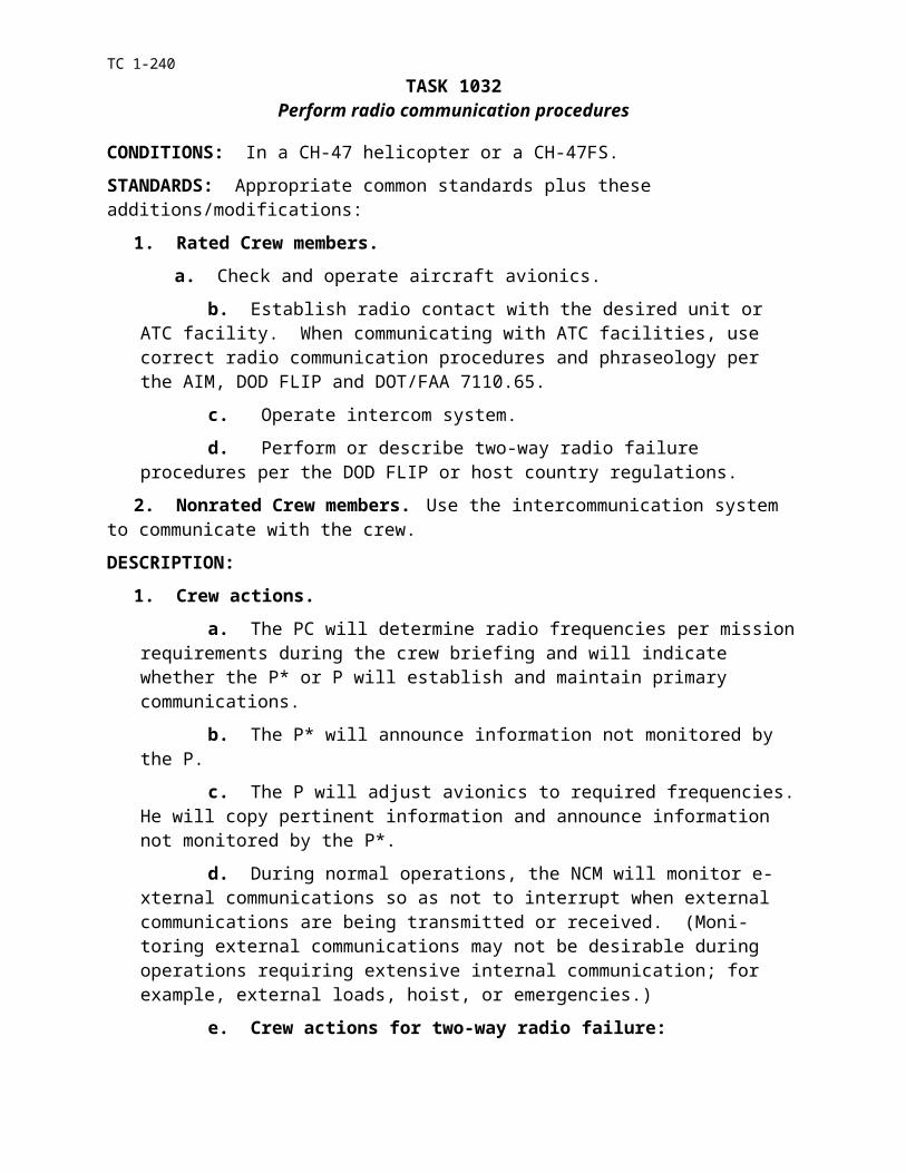
TC 1-240
TASK 1094Perform flight with AFCS-OFF
CONDITIONS: In a CH-47 helicopter VMC, or in a CH-47FS.
STANDARDS: Appropriate common standards plus the following additions/modifications:
1. Maintain trim flight ±1 ball width.
2. Maintain the standards for the task/maneuver being performed.
DESCRIPTION:
1. Crew actions. The P* or P will announce to the other crew members when he detects an AFCS malfunction. The P* will react positively and smoothly to divergent movements and enter all maneuvers slowly and avoid over controlling the aircraft. During VMC, the P* will focus pri-marily outside the aircraft to maintain aircraft control and obstacle clearance.
2. Procedures. The P* will smoothly coordinate control movements to maintain the aircraft in trim. He will monitor the turn-and-slip indicator for indications of divergent movements. The P* will smoothly but positively react to any divergent movements of the aircraft. The NCM will check that all passengers are wearing their seat belts and that all cargo and mission equipment is secured.
NOTE: Any maneuver in this ATM may be conducted with the AFCS-OFF except for external load hook-up. The standards for the maneuvers are the same as with the AFCS-ON. When conducting training flights with AFCS-OFF, the flight should be restricted to essential personnel only. RCM proficiency must be considered when tasks are selected for performance with the AFCS-OFF.
NIGHT OR NVG CONSIDERATIONS: To aid in preventing spatial disorientation, do not make large or abrupt attitude changes.
TRAINING AND EVALUATION REQUIREMENTS:
1. Training. Training may be conducted in the aircraft or simulator.
2. Evaluation. Evaluation will be conducted in the aircraft.
REFERENCES: Appropriate common references.
TC 1-240
TASK 1170Perform instrument takeoff
CONDITIONS: In a CH-47 helicopter or CH-47FS, in VMC or IMC, and with reference to in-struments only, with power and before take-off checks completed and aircraft cleared.
STANDARDS: Appropriate common standards plus these additions/modifications:
1. Set attitude indicator as required.
2. Correctly determine instrument take off power (hover power plus 10 % torque).
3. Maintain power as required (±2% torque).
4. Maintain accelerative climb attitude ±1 bar width until climb airspeed is attained.
5. Maintain takeoff heading ± 10 degrees until established of course.
6. Maintain the aircraft in trim after 40 KIAS.
7. Maintain an appropriate rate of climb ±100 FPM.
8. Maintain desired climb airspeed (±10 KIAS).
DESCRIPTION:
1. Crew actions.
a. The P* will focus primarily outside the aircraft during the VMC portion of the ma-neuver. He will announce when he initiates the maneuver and any intentions to alter or abort the takeoff. Before the aircraft enters simulated or actual IMC, he will make the transition to the flight instruments.
b. The P will announce when ready for takeoff and will focus primarily outside the air-craft to assist in clearing during the VMC portion of the maneuver and to provide adequate warning of obstacles. As the aircraft enters actual IMC, the P will monitor the flight instru-ments to assist in maintaining coordinated flight.
2. Procedures.
a. From the Ground. Align the aircraft with the desired takeoff heading. Set the atti-tude indicator for takeoff (wings-level on the horizon for CH-47D). Initiate the takeoff by in-creasing the thrust control smoothly and steadily, while maintaining a level attitude, until in-strument takeoff power is reached. When instrument takeoff power is established and the al-timeter and VSI show a positive climb, adjust pitch attitude below the horizon as required for the initial acceleration (not to exceed 10 degrees nose low). Visually maintain runway clear-ance and alignment on takeoff and transition to the flight instruments before entering IMC. At approximately 40 KIAS, the P* will check the turn-and-slip indicator to ensure that the aircraft is in trim. Maintain the heading/course required by the departure procedure or ATC instruc-tions. When the desired climb airspeed is reached, adjust cyclic to maintain airspeed and ad-just the thrust control to maintain the desired climb rate.
b. From a Hover. The P* will align the aircraft with the desired takeoff heading at the appropriate hover height. He will check the attitude indicator for the appropriate attitude. The P* will initiate the takeoff by increasing the thrust control smoothly and steadily, while maintaining a level attitude, until instrument takeoff power is reached. When the altimeter and VSI show a positive rate of climb, the P* will continue as in a takeoff from the ground.
TC 1-240NOTE 1. As the aircraft enters IMC the P should monitor the flight instruments and be prepared to accept a transfer of controls.
NOTE 2. When the crew is operating under simulated IMC, the NCM will position himself on the P* side of the aircraft for obstacle clearance and airspace surveillance.
TRAINING AND EVALUATION REQUIREMENTS:
1. Training. Training may be conducted in the aircraft or simulator.
2. Evaluation. Evaluation may be conducted in the aircraft or simulator.
REFERENCES: Appropriate common references.
TC 1-240TASK 1172
Perform radio navigation
CONDITIONS: In a CH-47 helicopter or CH-47FS, simulated IMC, or IMC, and with naviga-tion checks complete, with reference to instruments only and given appropriate navigational pub-lications.
STANDARDS: Appropriate common standards plus these additions/modifications:
1. Tune and identify appropriate NAVAID’s.
2. Determine, intercept, and maintain the desired course per FM 1-240 and FAR Part 91.
3. Identify station passage.
DESCRIPTION:
1. Crew actions.
a. The P* will remain focused inside the aircraft and will monitor radios and ATC in-formation. He will announce any deviation not directed by ATC or the P and will acknowl-edge all directives given by ATC or the P.
b. The P will select and announce radio frequencies. He also will monitor radios and ATC information not monitored by the P*.
c. During simulated IMC, the P and NCM will focus primarily outside the aircraft to provide adequate warning of traffic or obstacles. The NCM will position himself on the P* side of the aircraft.
2. Procedures.
a. Check all radio navigation equipment to be used during the mission. Equipment must be operable and within applicable tolerances, if applicable, as specified in FM 1-240 and TM 1-1520-240-10.
b. Select the appropriate NAVAID for the desired course (NDB, VOR, LOC, etc). Tune and identify the station. Determine the position of the aircraft in relation to the desired course, turn to an appropriate intercept heading. Maintain the intercept heading until ap-proaching an on-course indication. Depending on the rate of closure, start a turn to intercept the desired course.
c. Maintain an appropriate heading to track the desired course. If the navigational in-struments show an off-course condition, turn as necessary toward the course to re-intercept. If navigational instruments do not indicate movement toward the course within a reasonable time, increase the intercept angle. When re-intercepting the course, turn toward the course and apply the appropriate drift correction (normally one-half of the intercept angle). Continue to bracket the course by decreasing corrections until obtaining a heading that will maintain the aircraft on course. Determine arrival at radio intersections per procedures in FM 1-240. Identify station passage by observing the first complete reversal of the indicator needle and/or the TO-FROM indicator on the HSI.
TRAINING AND EVALUATION REQUIREMENTS:
1. Training. Training may and be conducted in the aircraft or simulator.
2. Evaluation. Evaluation may be conducted in the aircraft or simulator.
REFERENCES: Appropriate common references.
TC 1-240TASK 1174
Perform holding procedures
CONDITIONS: In a CH-47 helicopter or CH-47FS, simulated IMC, or IMC, with reference to instruments only, and given holding instructions and appropriate DOD FLIP.
STANDARDS: Appropriate common standards plus these additions/modifications:
1. Tune and identify the appropriate NAVAIDs.
2. Enter the holding pattern per FM 1-240, AIM and FAR Part 91.
3. Time and track holding pattern legs per FM 1-240 or host nation requirements.
DESCRIPTION:
1. Crew actions.
a. Before arrival at the holding fix, the P will analyze the holding instructions and determine the holding pattern and proper entry procedures. He will brief the other crew members on the proposed entry, outbound heading, and inbound course. He will select ra-dio frequencies, monitor radios, and announce ATC information not monitored by the P*. Also, the P will compute outbound times and headings to adjust for winds and direct the P* to adjust the pattern as necessary.
b. The P* will fly headings and altitudes and will adjust inbound and outbound times as directed by ATC or the P. He will announce any deviations as well as ATC infor-mation not monitored by the P.
c. During simulated IMC, the P and NCM will focus primarily outside the aircraft to provide adequate warning of traffic or obstacles. The NCM will position himself on the P* side of the aircraft.
2. Procedures. Upon arrival at the holding fix, turn (if required) to the predetermined out-bound heading. Maintain the outbound heading per DOD FLIP or as directed by ATC. After the appropriate time (or distance for TACAN) outbound, turn to the inbound heading and apply nor-mal tracking procedures to maintain the inbound course. Note the time required to fly the in-bound leg. When holding at a navaid, begin timing the outbound leg when abeam the station. When holding at an intersection, begin timing the outbound leg upon establishing the outbound heading.
TRAINING AND EVALUATION REQUIREMENTS:
1. Training. Training may be conducted in the aircraft or simulator.
2. Evaluation. Evaluation may be conducted in the aircraft or simulator.
REFERENCES: Appropriate common references.
TC 1-240TASK 1176
Perform non-precision approach
CONDITIONS: In a CH-47 helicopter or CH-47FS, simulated IMC or IMC, with reference to instruments only, given approach information and appropriate DOD FLIP approach clearance, with the before-landing checks complete.
STANDARDS: Appropriate common standards plus these additions/modifications:
1. Execute the approach per AR 95-1, FM 1-240, AIM and the DOD FLIP.
2. Maintain NDB, VOR, or TACAN course centerline ±5° (1 dot CDI deflection).
3. Maintain LOC course centerline ±2.5° (2 dot CDI deflection).
4. During ASR approaches, make immediate heading and altitude changes issued by ATC and maintain heading ±5 degrees.
5. Comply with descent minimums prescribed for the approach.
6. Perform the correct missed approach procedure per DOD FLIP or ATC instruction upon reaching the MAP if landing cannot be accomplished per AR 95-1.
DESCRIPTION:
1. Crew actions.
a. Each RCM will review and confirm the specific approach to be flown before initiating the procedure. The crew will confirm that the correct navaid/communication fre-quencies are set, and the HSI and HSI mode select panel are set as required.
b. The P* will focus primarily inside the aircraft on the instruments and perform the approach. He will follow the heading/course, altitude, and missed approach directives issued by the P/ATC. He will announce any deviation not directed by ATC or the P and will acknowledge all navigation directives given by the P.
c. The P will call out the approach procedure to the P* and will advise the P* of any unannounced deviations. He will monitor outside for the landing environment, an-nounce when he makes visual contact suitable to complete the landing per AR 95-1, and if directed by the P*, take the controls to complete the landing. If visual contact is not made by the missed approach point, he will announce such and call out the missed approach pro-cedures.
d. During simulated IMC, the P and NCM will focus primarily outside the aircraft to provide adequate warning of traffic or obstacles. The NCM will position himself on the P* side of the aircraft.
2. Procedures. Perform the desired approach procedures per AR 95-1, DOD FLIP, FM 1-240, and TM 1-1520-240-10.
NOTE: Use of the Doppler/GPS as an IFR navigational system is not authorized; however, its use should be considered and planned for as an emergency backup system.
TC 1-240TRAINING AND EVALUATION REQUIREMENTS:
1. Training. Training may be conducted in the aircraft or simulator.
2. Evaluation. Evaluation may be conducted in the aircraft or simulator.
REFERENCES: Appropriate common references.
TC 1-240TASK 1178
Perform precision approach
CONDITIONS: In a CH-47 helicopter or CH-47FS, simulated IMC or IMC with reference to instruments only, given approach information and appropriate DOD FLIP approach clearance, and the before-landing checks complete.
STANDARDS: Appropriate common standards plus these additions/modifications:
1. Execute the approach per AR 95-1, FM 1-240, AIM and the DOD FLIP.
2. For an ILS approach, maintain the LOC centerline 2.5 (2 dot CDI deflection) and the glide slope indicator within full scale deflection.
3. For a PAR approach, make immediate heading and altitude changes issued by ATC and maintain heading ±5 degrees; for final approach, maintain glide slope as directed by ATC.
4. Comply with the DH prescribed for the approach.
5. Perform the correct missed approach procedure per DOD FLIP or ATC instruction upon reaching the DH if landing cannot be accomplished per AR 95-1.
DESCRIPTION:
1. Crew actions.
a. Each RCM will review and confirm the specific approach to be flown before initiating the procedure. The crew will confirm that the correct navaid/communication fre-quencies are set, and the HSI and HSI mode select panel are set as required.
b. The P* will focus primarily inside the aircraft on the instruments and perform the approach. He will follow the heading/course, altitude, and missed approach directives issued by the P/ATC. He will announce any deviation not directed by ATC or the P and will acknowledge all navigation directives given by the P.
c. The P will call out the approach procedure to the P* and will advise the P* of any unannounced deviations. He will monitor outside for the landing environment, an-nounce when he makes visual contact suitable to complete the landing per AR 95-1, and if directed by the P*, take the controls to complete the landing. If visual contact is not made by the missed approach point, he will announce such and call out the missed approach pro-cedures.
d. During simulated IMC, the P and NCM will focus primarily outside the aircraft to provide adequate warning of traffic or obstacles. The NCM will position himself on the P*’s side of the aircraft.
2. Procedures. Perform the desired approach procedures per AR 95-1, DOD FLIP, FM 1-240, and TM 1-1520-240-10.
TRAINING AND EVALUATION REQUIREMENTS:
1. Training. Training may be conducted in the aircraft or simulator.
2. Evaluation. Evaluation may be conducted in the aircraft or simulator.
REFERENCES: Appropriate common references.
TC 1-240TASK 1182
Perform unusual attitude recovery
CONDITIONS: In a CH-47 helicopter in VMC, simulated IMC or in a CH-47FS in IMC and with reference to instruments only.
STANDARDS: Appropriate common standards plus these additions/modifications:
1. Analyze aircraft attitude.
2. Without delay, use correct recovery procedures with minimum loss of altitude.
a. Attitude – Level the wings and pitch attitude while maintaining the aircraft in trim.
b. Heading – Establish and maintain appropriate heading.
c. Torque – Adjust to cruise or climb power.
d. Airspeed – Maintain the desired airspeed.
e. Altitude – Return to the appropriate/desired altitude after establishing aircraft con-trol.
3. Recover without exceeding aircraft operating limitations.
DESCRIPTION:
1. Crew actions.
a. The trainer or evaluator will place the aircraft in unusual attitude and transfer the controls to the P. The P will acknowledge the transfer of controls, the unusual attitude, and recover the aircraft as P*.
b. During recovery the P* will remain focused inside the aircraft.
c. The P will assist in monitoring the aircraft instruments, and call out attitude, torque, and trim as necessary.
d. During simulated IMC, the P and NCM will focus primarily outside the aircraft to provide adequate warning of traffic and obstacles. The NCM will position himself on the P* side of the aircraft.
2. Procedures. To recover from an unusual attitude, correct the pitch and bank attitude, trim the aircraft as required and adjust power to return to level flight. All components are changed simultaneously with little lead of one over the other. The displacement of controls used in recoveries may be greater than those for normal flight. Care must be taken in making adjust-ments as straight-and-level flight is approached. The instruments must be observed closely to avoid over controlling.
TRAINING AND EVALUATION REQUIREMENTS:
1. Training. Training may be conducted in the aircraft or simulator.
2. Evaluation. Evaluation will be conducted in the aircraft or simulator.
REFERENCES: Appropriate common references.
TC 1-240TASK 1184
Respond to inadvertent IMC
CONDITIONS: In a CH-47 helicopter simulated IMC or in a CH-47FS or academically.
STANDARDS: Appropriate common standards plus these additions/modifications:
1. Announce “IMC”, maintain proper aircraft control, and make the transition to instrument flight immediately.
2. Immediately initiate a climb.
3. Continue IIMC recovery procedures as follows:
a. Attitude – Level the wings and adjust pitch for desired airspeed while maintaining the aircraft in trim.
b. Heading – Maintain heading; turn only to avoid known obstacles.
c. Torque – Maintain climb power until reaching appropriate cruise altitude.
d. Airspeed – Adjust to appropriate climb airspeed.
4. Complete the inadvertent IMC recovery per local regulations and policies.
DESCRIPTION:
1. Crew actions.
a. The P* will announce “Inadvertent IMC”, immediately initiate a climb, and es-tablish aircraft control while transitioning to the instruments. He will immediately an-nounce if he becomes disoriented.
b. The P will announce “inadvertent IMC” and monitor the cockpit instruments to assist in recovery. He will announce when the aircraft is in a positive climb, the altitude and altitude climbing to, and the heading. He will adjust the transponder to emergency, adjust the navigational radios as appropriate, and make the appropriate radio calls. He will perform any other tasks as directed by the P* and always remain prepared to take the controls should the P* become disoriented.
c. The NCM will focus primarily outside the aircraft to provide adequate warning for avoiding terrain or obstacles and will announce if VMC conditions are encountered. The NCM will perform any other tasks as directed by the P*/P.
2. Procedures. The crew should consider establishing a torque and airspeed appropriate for the mission environment to use in the event of encountering IIMC. If briefed during the crew briefing, this can help eliminate confusion during the actual emergency. The most important ac-tion upon encountering IIMC is to immediately begin climbing while establishing aircraft control via the instruments. Once this is accomplished, the transponder should be set to emergency to alert ATC. Tuning navigational radios or making radio calls will be determined by local proce-dures. The crew should contact ATC on Guard and allow ATC to assign an appropriate altitude and heading/course and if necessary a frequency. If radio contact cannot be established first, the crew must ensure navigational radios are tuned as quickly as possible to determine the aircraft’s position and appropriate course for recovery.
NIGHT OR NVG CONSIDERATIONS: When using NVGs, it may be possible to see thro-ugh a thin obscuration, such as fog and drizzle, with little or no degradation. The NVGs may be removed or flipped up once stable flight is established.
TC 1-240SNOW/SAND/DUST CONSIDERATIONS: Obscurants other than weather can induce loss of visual contact. At low altitudes where these conditions would be encountered it is extremely im-portant that these procedures be initiated immediately to prevent ground contact.
NOTE: If IMC conditions are entered with the IR searchlight or landing light on, spatial disorientation may occur. Low-level ambient light may induce visual illusions and spatial disorientation. During NVG operations, video noise may contribute to loss of visual cues.
TRAINING AND EVALUATION REQUIREMENTS:
1. Training. Training may be conducted in the aircraft, simulator or academically.
2. Evaluation. Evaluations will be conducted in the aircraft or simulator.
REFERENCES: Appropriate common references.
TC 1-240TASK 1188
Operate aircraft survivability equipment
CONDITIONS: In a CH-47 helicopter or CH-47FS equipped with ASE or academically.
STANDARDS: Appropriate common standards plus these additions/modifications:
1. Rated.
a. Describe the purpose of each installed item of ASE.
b. Perform/describe preflight inspection, turn-on, test, operation, emergency proce-dures, and shut down of installed ASE.
c. Determine partial failure alternatives.
d. Employ/describe use of installed ASE.
2. Nonrated. Prepare equipment for operation.
DESCRIPTION:
1. Crew actions.
a. The PC will ensure that crew members understand the employment of installed ASE during the conduct of the mission. He will also ensure that all ASE payloads and set-tings are IAW the mission briefing.
b. When the crew encounters a radar directed threat, the P* will remain primarily focused outside to avoid obstacles, perform the required evasive maneuver, reposition the aircraft as necessary to break lock, and then avoid the threat.
c. The P will begin dispensing flares by pressing the dispense button, or ensuring that the mode switch is in PGRM as required. The P and NCM will assist in clearing the aircraft and provide adequate warning of obstacles.
d. The NCM will remove and install safety pin(s) IAW the operator’s manual/CL.
2. Procedures.
a. Perform or describe preflight inspection, turn-on, test, operation, emergency procedures, and shutdown of installed ASE equipment. Evaluate and interpret the ASE vis-ual and aural indications.
b. Execute mission employment per doctrine, and determine failure alternatives.
TRAINING AND EVALUATION REQUIREMENTS:
1. Training. Training may be conducted in the aircraft, simulator, or academically.
2. Evaluation. Evaluation will be conducted in the aircraft or academically.
REFERENCES: Appropriate common references plus the following:
ASET ProgramsFM 1-101Unit S-2Equipment operator manuals
TC 1-240TASK 1190
Perform/identify hand and arm signals
CONDITIONS: Given a list of hand and arm signals from FM 21-60 to identify or perform.
STANDARDS: Appropriate common standards plus these additions/modifications:
1. Rated. Identify at a minimum the hand and arm signals required for moving an aircraft left, right, forward, or backward and those for takeoff, landing, sling load hooked, and release sling load, as appropriate, as per FM 21-60.
2. Nonrated. Identify and perform at a minimum the hand and arm signals required for mov-ing an aircraft left, right, forward, or backward and those for takeoff, landing, sling load hooked, and release sling load as per FM 21-60.
DESCRIPTION: Identify or perform the hand and arm signals required to move an aircraft from one point to another.
TRAINING AND EVALUATION REQUIREMENTS:
1. Training. Training will be conducted academically.
2. Evaluation. Evaluation will be conducted academically.
REFERENCES: Appropriate common references plus the following:
FM 21-60
TC 1-240TASK 1194
Perform refueling operations
CONDITIONS: With a CH-47 helicopter with refueling equipment or academically.
STANDARDS: Appropriate common standards plus these additions/modifications:
1. Ensure that safety procedures are complied with and all individuals are wearing the appro-priate protective clothing per FM 10-67-1, the operator’s manual/CL, and FM 1-113.
2. Ensure that all doors, windows, and vents are closed on the refueling side (for hot refuel-ing operations).
3. Ensure that the aircraft is refueled per FM 10-67-1, Operator’s Manual/CL, FM 1-113, and the unit SOP.
4. Enter the appropriate information on DA Form 2408-12.
DESCRIPTION:
1. Crew actions cold refueling.
a. A crew member will guide the refueling vehicle to the aircraft. Ensure that the driver parks the vehicle the proper distance from the aircraft per FM 10-67-1. Verify that all personnel not involved with the refueling operation are a safe distance away.
b. Ground and refuel the aircraft per FM 10-67-1, Operator’s Manual/CL, and the unit SOP. Ensure that the tanks are filled to the required level. When the refueling is com-pleted, ensure that all caps are secured and remove the ground connection if the aircraft will not remain parked. Make the appropriate entries on DA Form 2408-12.
2. Crew actions hot refueling.
a. The P and NCM will assist the P* in positioning the aircraft. Ensure that the proper separation is maintained between the fuel source, the aircraft, and the refueling equipment. Before refueling the aircraft, the PC will verify that personnel not involved with the refueling operation are a safe distance away.
b. The crew member outside will ensure that the aircraft is grounded, refuel the aircraft per FM 10-67-1, Operator’s Manual/CL, the unit SOP, and assist with the refueling operation. Ensure that the tanks are filled to the required level. When the refueling is com-pleted, ensure that all caps are secured and remove the ground connection.
c. The crew member outside will inform the PC when the refueling is completed. Assist passengers in boarding the aircraft and in securing their seat belts. Assist the P* and P in clearing the aircraft during the departure from the refueling area. Make the appropriate entries on DA Form 2408-12.
NIGHT OR NVG CONSIDERATIONS: Supplement aircraft lighting at the refueling station by using a flashlight with an unfiltered lens to check for leaks and fuel venting.
TRAINING AND EVALUATION REQUIREMENTS:
1. Training. Training will be conducted in the aircraft or academically.
2. Evaluation. Evaluation will be conducted in the aircraft or academically.
TC 1-240
REFERENCES: Appropriate common references plus the following:
DA Pamphlet 738-751 FM 1-104 FM 10-67-1 FM 21-60 FM 1-113
TC 1-240TASK 1200
Perform NCM duties during a maintenance test flight
WARNING
When standing on the engine work platform with the engine operating, the NCM must keep all clothing, tools, and body parts away from the engine inlet and bleed band areas.
CAUTION
While on the ground, do not leave the pitot heaters on for more than 5 minutes. Ex-tended ground operation with the pitot heaters on shortens the service life.
CONDITIONS: In a CH-47 helicopter or academically in a classroom environment and given CH-47 MTF.
STANDARDS: Appropriate common standards plus these additions/modifications:
1. Perform or describe appropriate maintenance procedures and checks per CH-47 MTF.
2. Perform or describe maintenance procedures and checks directed by the MP.
3. Immediately inform the MP of any malfunction or discrepancy detected during the main-tenance procedures or checks.
DESCRIPTION:
1. Crew actions.
a. If two or more NCMs are performing crew duties during the test flight, the FE will ensure they are briefed on their duties and responsibilities.
b. NCMs will perform duties and responsibilities per CH-47 MTF and CH-47 -23 series. If any procedure is conducted or the result is not IAW applicable maintenance or troubleshooting manual the MP will be notified
2. Procedures.
a. Before and during the test flight, the NCM must constantly monitor all aircraft systems and components. He will inform the MP of any unusual vibrations, noises, smells, leakage, or component malfunctions. The CE also will perform any maintenance proce-dures and checks required by the MP.
b. Prior to flight, the NCM will remove any additional panels, covers, and cowl-ings required by the MP. If the DASH actuator is required for a mechanical rig check, the NCM will set it to 36 inches and disconnect the electrical connectors.
c. The NCM will make the following checks:
(1) Maintenance panel check. The NCM will check the maintenance panel per CH-47 MTF. He will check and announce each individual hydraulic system pressure (maxi-mum fluctuation +/- 50 psi) and press to test all panel lights. The NCM will ensure that the XMSN main and AUX press lights and ground contact lights remain on. He will announce when he ground tests the latch indicators and checks all indicators for proper operation.
TC 1-240(2) Cargo hooks and winch. The NCM will ensure the cargo hook area and
winch are clear of obstructions and non-flight personnel are at a safe distance. Ensure cargo hook and winch operational check is conducted IAW CH-47 MTF.
(3) Cargo ramp and door. The NCM will ensure the ramp area is clear of obstruction. Check APU start accumulator for minimum pressure IAW the operator’s manual. Ensure the Ramp control handle is down and ramp is level with cabin floor. Ensure ramp opera-tional check is IAW CH-47 MTF.
(4) Lights. The NCM will assist the P* in checking and setting their search-lights and will notify the MP that the anti collision, position, and formation lights are operational.
(5) Swivel locks check. The NCM will check the swivel lock actuators and inform the MP of their position (locked or unlocked).
(6) Ramp Isolation check. The NCM will lower the ramp until it rests on the ground and will place the ramp control handle in the STOP position. When the MP announces “Ramp isolation switch OFF,” the NCM will attempt to raise the ramp and will give the MP the appropriate response.
(7) Fire-pull handle and cross-feed fuel valve checks. The NCM will posi-tion himself to observe the fuel and cross-feed valves when the MP pulls the fire pull handle or places the cross-feed valve switch to the open position, the NCM will check the fuel valves and appropriate lights for proper operation. The MP pushes in the fire pull handle or places the cross-feed valve switch to the closed position; the NCM will check the valves and lights for proper operation.
(8) Flight control travel and hydraulic check. The NCM will check the hy-draulic gauges on the maintenance panel and notify the MP when a pressure has dropped or re-turned to normal. During the control interlock check, the NCM will tell the MP the pressures at which the flight control hydraulic systems change over.
(9) Pitot anti-ice system check. The NCM will check both pitot tubes, pilots, and co-pilots yaw-port heat for proper operation.
(10) Bleed band closure check. The NCM will position himself on the en-gine work platform where he can observe the engine bleed band. He must continue to communi-cate with the MP and should turn his head away from the engine when keying the intercom. The NCM will observe the opening and closing of the bleed band and will give the MP the appropri-ate response.
(11) Mechanical rig check. When called for by the MP, the NCM will recon-nect the electrical connectors on the DASH actuator. The NCM will announce when he is recon-necting the electrical connectors and when they are connected and flight control closet sound-proofing is reinstalled.
TRAINING AND EVALUATION REQUIREMENTS:
1. Training. Training may be conducted in the aircraft or academically.
2. Evaluation. Evaluations will be conducted in the aircraft or academically.
REFERENCES: Appropriate common references plus the following: CH-47 MTF.
TC 1-240TASK 1202
Perform Auxiliary Power Unit operations (APU)
WARNING
Aircraft Survivability Systems (ASE), when energized may cause thermal burns or blindness when personnel are too close to an active system. Observe all Operators’ Manual warnings and cautions.
CONDITIONS: In a CH-47 helicopter with a qualified and current APU operator.
NOTE: This task only applies to NCMs.
STANDARDS: Appropriate common standards plus these additions/modifications:
1. Preflight all systems to be operated during APU operations.
2. Operate APU, systems, and equipment IAW the operator’s manual/CL
3. Shutdown systems, equipment and APU IAW the operator’s manual/CL
4. Perform or describe appropriate emergency procedures for APU fire according to Opera-tors Manual.
5. Enter appropriate information if required on DA Forms 2408-12, -13, and DA Form 13-1.
DESCRIPTION:
1. Crew actions.
a. The NCM will coordinate with and brief any additional ground support person-nel prior to APU start. Perform pre-flight inspection of the APU. Ensure that the rotor blade tie-downs are removed if PTU operation is required. He will brief all concerned personnel on procedures to be followed in case of an emergency. The NCM will direct assistance from any additional ground support personnel to aid in maintaining the APU exhaust areas clear during the APU start sequence and any subsequent ground checks.
b. Additional ground support personnel should assist the NCM as directed.
2. Procedures.
a. Before starting APU. Brief the additional ground support personnel as neces-sary. Review aircraft logbook for any faults, which would prevent operation of the APU, APU generator, or power transfer units (PTUs). Perform pre-flight inspection of the APU and check APU exhaust cover, rotor blade tie-downs, and fluid levels. Check APU start ac-cumulator and signal accumulator for proper pressure for starting APU IAW Operator’s Manual. Ensure that the emergency utility pressure valve and utility reservoir depressuriza-tion valve handles are in the NORMAL position. Ensure that emergency fuel shut-off valve is OPEN. Connect aircraft battery and battery charger and ensure all cockpit switches are OFF.
b. Starting Procedures. With fireguard posted, place battery switch in the ON position and check Master Caution panel for UTIL HYD PRESS caution light ON and APU ON caution or advisory light extinguished. Set APU switch to RUN position for 3 to 5 sec-onds then to the START position for 2 seconds and release the switch. Check Master Cau-tion panel for APU ON caution or advisory light to be illuminated and the UTIL HYD PRESS caution light to be extinguished. Set the APU GEN switch to ON and check Master
TC 1-240Caution panel to ensure that No.1 and No.2 XFR RECT lights go out. If power transfer units are required, set PTU No. 1 and No.2 switches to the ON position while checking the Master Caution panel to ensure the HYD FLT CNTL 1 and HYD FLT CNTL 2 caution lights are out.
NOTE 1. If the UTIL HYD PRESS caution light does not extinguish within 30 seconds after APU caution or advisory light comes on, place the APU switch to OFF
NOTE 2. If a HYD FLT CNTL caution light does not go out in 30 seconds, set the affected PTU system to the OFF position.
c. Shutdown Procedures. Before shutdown of the APU, all electrical equipment that was switched ON should be turned OFF. Neutralize the flight controls then place PTU switches to the OFF position. Set the APU GEN switch to the OFF position. Set APU switch to the OFF position. Place the BATT switch to the OFF position and disconnect the battery and battery charger cables.
3. Emergency Procedures. In the event of an APU fire, APU fuel manual shutoff valve should be set to the OFF position, APU switch to OFF, BATT switch to the OFF position, and the crew should make every effort to fight the fire. If the APU should ever be shut down prema-turely, set APU switch to the OFF position, check ESU for BITE indications.
NIGHT OR NVG CONSIDERATIONS: During night operations ensure adequate lighting (anti-collision, position lights) are on and fire guard has a flashlight. This task is prohibited while wearing NVGs.
TRAINING AND EVALUATION REQUIREMENTS:
1. Training. Training will be conducted in the aircraft.
2. Evaluation. Evaluation will be conducted in the aircraft.
REFERENCES: Appropriate common references.
DA PAM 738-751TM 1-1520-240-PMDTM 1-1520-240-23 SERIES
TC 1-240TASK 1262
Participate in a crew-level after-action review
CONDITIONS: After flight in a CH-47 helicopter or a CH47FS and given a unit-approved crew-level after-action review checklist.
STANDARDS: Appropriate common standards plus these additions/modifications:
1. PC/AMC will conduct a detailed crew-level after-action review using a unit-approved crew-level after-action review checklist after each flight.
2. All crew members will actively participate in the review.
DESCRIPTION:
1. Crew actions.
a. The PC will conduct a crew-level after-action review. He will use a unit-approved checklist. The PC will actively seek input from all crew members. He will ensure that the re-sults of the review are passed to operations and flight standards.
b. All crew members will actively participate in the review. The intent is to construc-tively review the mission and apply lessons learned into subsequent missions.
2. Procedures. Using an after-action review checklist, participate in a crew-level after-ac-tion review of the mission. Figure 4-6 shows the minimum mandatory items required for a crew after-action review checklist. The review should be an open and frank discussion of all aspects of the mission. It should include all factors of the mission and incorporate all crew members. The results of the review should be passed to operations and flight standards.
TRAINING AND EVALUATION REQUIREMENTS:
1. Training. Training will be conducted academically.
2. Evaluation. Evaluation will be conducted academically.
REFERENCES: Appropriate common references.
TC 1-240
CREW-LEVEL AFTER-ACTION REVIEW CHECKLIST
1. Restate mission objectives with METT-T considerations.2. Conduct review for each mission segment: a. Restate planned actions/interactions for the segment. b. What actually happened? (1) Each crew member states in own words. (2) Discuss impacts of crew coordination requirements, aircraft/equipment operation, tactics, commander's intent, etc. c. What was right or wrong about what happened? (1) Each crew member states in own words. (2) Explore causative factors for both favorable and unfavorable events. (3) Discuss crew coordination strengths and weakness in dealing with each event. d. What must be done differently the next time? (1) Each crew member states in own words. (2) Identify improvements required in the areas of team relationships, mission planning, workload distribution and prioritization, information exchange, and cross monitoring of performance. e. What are the lessons learned? (1) Each crew member states in own words. (2) Are changes necessary to: (a) Crew coordination techniques? (b) Flying techniques? (c) SOP? (d) Doctrine, ATM, TMs?3. Effect of segment actions and interactions on the overall mission. a. Each crew member states in own words. b. Lessons learned. (1) Individual level. (2) Crew level. (3) Unit level. 4. Advise unit operations of significant lessons learned.
Figure 4-6. Suggested format crew-level after-action review checklist

TC 1-240TASK 1413
Perform actions on contact
CONDITIONS: In a CH-47 helicopter, CH-47FS or academically.
STANDARDS: Appropriate common standards plus use the correct actions on contact consis-tent with the tactical situation.
1. If appropriate, immediately deploy to a covered and concealed position using suppressive fires.
2. Continue observation as appropriate for the mission.
3. Transmit tactical report per SOI, unit SOP or mission briefing.
DESCRIPTION:
1. Crew actions. When engaged by or upon detecting the enemy, the crew member identi-fying the threat will announce the nature (visual observation, radar detection or hostile fire) and the direction of the threat.
a. Proper pre-mission planning and intelligence data may aid in developing flight pro-files and route selection in order to avoid hostile fire.
b. Fly the helicopter to a concealed area, using the evasive techniques below and sup-pressive fire, as required. Choose a course of action that supports the mission and the intent of the unit commander's directives. For additional information, see Task 2022; Transmit tactical report.
c. If engaged by the enemy, the crew will announce the nature of the threat (hostile fire or radar detection) and the direction of the threat. The crewmember that first identified the threat is responsible to announce the threat bearing relative to the aircraft and launch counter-measures/suppressive fire as necessary.
d. The P* will announce the direction of flight to deploy to cover and remain focused outside the aircraft during the evasive maneuver and clearing.
e. Avoid over-controlling/excessive maneuvering that may result in loss of aircraft control or insufficient power to recover from the maneuver.
f. The P and NCM will remain focused primarily outside the aircraft and announce ad-equate warning to avoid obstacles detected during the evasive
g. The P will remain oriented on threat location. He will announce warnings to avoid obstacles and when his attention is focused inside the aircraft, again when attention is reestab-lished outside, and transmit a tactical report.
h. The NCM will remain focused primarily outside the aircraft and announce adequate warning to avoid obstacles. He will also provide suppressive fire as required.
NOTE: The NCM(s) must be able to transmit a tactical report per the SOI, unit SOP or mission briefing.
2. Procedures.
a. The specific maneuver required will depend on the type of hostile fire encountered. The guidance below may be helpful in developing actions on contact for the given threat system. A thorough intelligence briefing will assist with what actions on contact the crew can expect to take with regards to the most probable threat system employment.
TC 1-240(1) Tanks and small arms. If concealment is available, deploy toward the
area of concealment. If concealment is not readily available, immediately turn to an oblique angle while applying forward cyclic. This action will allow the aircraft to accelerate while descending in an attempt to mask the aircraft. Additionally, turning to an oblique angle from the hostile fire will minimize the aircrafts profile making for a more difficult target. Make turns of unequal magnitude and at unequal intervals and small changes in altitude to provide the best protection until you are beyond the effective range of hostile weapons. If the situation permits, employ immediate suppressive fire.
(2) Large caliber, antiaircraft fire (radar-controlled). Execute an immediate 90-degree turn, deploy chaff, and mask the helicopter. After turning, do not maintain a straight line of flight or the same altitude for more than 10 seconds before initiating a second 90-degree turn. To reduce the danger, descend immediately to NOE altitude.
(3) Fighters. Upon sighting a fighter, try to mask the helicopter. If the fighter is alone and executes a dive, turn the helicopter toward the attacker and descend. This maneuver will cause the fighter pilot to increase his attack angle. Depending on the fighter's dive angle, it may be advantageous to turn sharply and maneuver away once the attacker is committed. The fighter pilot will then have to break off his attack to recover from the maneuver. Once he breaks off his attack, maneuver the helicopter to take advantage of terrain, vegetation, and shadow for concealment.
(4) Heat-seeking missiles.
a. M-130: Try to keep helicopter heat sources away from the threat. If a missile is sighted, turn the tail of the helicopter away from the missile while applying forward cyclic and mask the helicopter. As appropriate, employ the aircraft survivability equipment to counter heat-seeking devices while maneuvering to avoid the threat.
b. ALE-47: Maintain course and allow the counter-measure system to defeat the threat.
(5) Antitank-guided missiles. Some missiles fly relatively slowly and can be avoided by rapidly repositioning the helicopter. If terrain or vegetation is not available for masking, remain oriented on the missile as it approaches. As the missile is about to impact, rapidly change flight path or altitude to evade it.
(6) Artillery. Depart the impact area, and determine NBC requirements.
(7) Radar-guided missiles. Maneuver the helicopter to break the line of sight to the radar source while simultaneously activating chaff if available.
NOTE: Dispensing chaff while maneuvering may cause tracking radars to break lock.
b. After successfully deploying to cover, the crew will--
(1) Report the situation.
TC 1-240(2) Develop the situation.
(3) Choose a course of action if not directed by the unit commander. (The P*/P will announce the unit commander's directive if not monitored by the other crew member.)
(4) If hit by hostile fire, rapidly assess the situation and determine an appropriate course of action.
Assess aircraft controllability.
Check all instruments and warning and caution lights. If a malfunction is indicated, initiate the appropriate emergency procedure.
If continued flight is possible, take evasive action.
Make a radio call to report your situation, location, action and request assistance if desired.
Continue to be alert for unusual control responses, noises, and vibrations.
Monitor all instruments for an indication of a malfunction.
Fly the aircraft to the nearest secure location and land.
After landing, inspect the aircraft to determine the extent of damage and whether flight can be continued.
NOTE 1: Proper employment of terrain flight techniques will reduce exposure to enemy threat weapon systems.
NOTE 2: Threat elements will be harder to detect. Rapid evasive maneuvers will be more hazardous due to division of attention and limited visibility. Maintain situational awareness with regard to threat and hazard location.
NOTE 3: Performing this maneuver in certain environments may require hover OGE power. Evaluate each situation for power required versus power available.
NOTE 4: The crew must treat visual obstacles the same as physical obstacles.
NIGHT OR NVG CONSIDERATIONS:
1. At low ambient light levels, obstacle detection is difficult. The P* may experience spatial disorientation if he executes abrupt maneuvers. Proper scanning techniques and good cockpit communication are necessary to avoid these hazards.
2. The crew should consider using artificial lighting if the ambient light level is insufficient for obstacle detection.
REFERENCES: Appropriate common references plus the following:
ASET ProgramsFM 34-25-7FM 1-101
TC 1-240TASK 1474
Respond to NVG failure
CONDITIONS: In a CH-47 helicopter, a CH-47FS, or academically.
STANDARDS: Appropriate common standards plus these additions/modifications:
1. Identify or describe the indications of impending NVG failure.
2. Perform or describe emergency procedures for NVG failure.
DESCRIPTION:
1. Crew actions. Upon detection of goggle failure perform the following crew actions:
a. In flight the P* will announce “goggle failure” and start a climb if conducting terrain flight, and transfer the flight controls.
b. The P must be ready to assume aircraft control if the P* announces goggle failure. If the P announces goggle failure, he will perform emergency procedures for NVG failure.
c. If the NCM announces goggle failure, he will perform emergency procedures for NVG failure.
d. All crew members must be prepared to assume the scan sector assigned to the crew member whose goggles have failed.
e. The PC will determine how a crew member's goggle failure affects the mission and any required deviations.
2. Procedures. Impending NVG, failure may be indicated by flickering or dimming of the view image or by illuminating the low-battery indicator on the visor mount. If the NVG fails, perform the following procedure:
a. Immediately announce "goggle failure" and crew position.
b. Attempt to restore NVG power by selecting the alternate battery.
c. Advise the crew of restored vision or continued failure.
d. If NVGs are not restored, revise or abort the mission.
NOTE: NVG tube failure is infrequent and is usually preceded by ample warning such as intermittent operation. At low altitudes, the P* should consider turning on the landing light.
TRAINING AND EVALUATION REQUIREMENTS:
1. Training. Training may be conducted in the aircraft or simulator.
2. Evaluation. Evaluation will be conducted in the aircraft.
REFERENCES: Appropriate common references.
TC 1-240TASK 2010
Perform multi-aircraft operations
CONDITIONS: In a CH-47 helicopter with the mission briefing completed.
STANDARDS: Appropriate common standards plus these additions/modifications:
1. Rated.
a. Maneuver into the flight formation.
b. Change position in the flight formation when required.
c. Maintain proper horizontal and vertical separation for the type of formation flight being conducted.
d. Perform techniques of movement, if required.
2. Nonrated.
a. Assume a position in the helicopter as briefed to observe other aircraft in the forma-tion.
b. Announce if visual contact is lost with other aircraft.
DESCRIPTION:
1. Crew actions.
a. The P* will focus primarily outside the aircraft for clearing and keeping track of other aircraft. He will announce any maneuver or movement before execution and inform the P and NCM if visual contact is lost with other aircraft. He will ensure the appropriate ra-dio calls are made during IMC breakup.
b. The P and NCM will provide adequate warning of traffic or obstacles detected in the flight path and identified on the map. They will inform the P* if visual contact is lost with other aircraft, if an enemy is sighted, when their attention is focused inside the aircraft, and again when attention is reestablished outside. The PC will call out direction and altitude in case of IMC breakup.
c. The NCM will position themselves in the aircraft to observe other aircraft in the formation and assist in maintaining aircraft separation and obstacle clearance.
2. Procedures.
a. Perform formation flight per AR 95-1, TC 1-201, TC 1-204, TC 1-210, FM 90-4, and the unit SOP.
b. If the tactical situation requires, perform techniques of movement per TC 1-201.
NIGHT OR NVG CONSIDERATIONS: Closure rates are more difficult to determine. Keep changes in the formation to a minimum. All crew members must avoid fixation by using proper scanning techniques.
1. Night. During unaided night flight, the crew should use formation and position lights to aid in maintaining the aircraft's position in the formation.
TC 1-2402. NVG. When conducting NVG formation flight, the crew should use the IR formation
lights to maintain the aircraft's position in the formation. Additional crew member requirements are in TC 1-210. The NCM who is not engaged in observing other aircraft in the formation will perform flight duties not related to the formation and other duties directed by the PC.
TRAINING AND EVALUATION REQUIREMENTS:
1. Training. Training will be conducted in the aircraft.
2. Evaluation. Evaluation will be conducted in the aircraft.
REFERENCES: Appropriate common references plus:
FM 90-4.
TC 1-240
TASK 2012Perform tactical flight mission planning
CONDITIONS: Before flight in a CH-47 helicopter, or CH-47FS, and given a mission briefing, navigational maps, a navigational computer, Army approved mission planning station and soft-ware (if available), and other flight planning materials as required.
STANDARDS: Appropriate common standards plus these additions/modifications:
1. Analyze the mission using the factors of mission, enemy, terrain, troops and time avail-able (METT-T).
2. Operate the Army approved mission planning station and software (if available).
3. Perform a map/photo reconnaissance using the available map media, photos Army ap-proved mission planning station and software. Ensure that all known hazards to terrain flight are plotted.
4. Select the appropriate terrain flight modes.
5. Select appropriate primary and alternate routes and enter all of them on a map, route sketch, or into the Army approved mission planning station and software (if available).
6. Determine the distance ±1 kilometer, ground speed ±5 knots and ETE ±1 minute for each leg of the flight.
7. Determine the fuel required and reserve per AR 95-1 ±100 pounds.
8. Obtain and analyze weather briefing to determine that weather and environmental condi-tions are adequate to complete the mission.
9. Load mission data to data transfer cartridge (if available).
10. Print out TDH cards, waypoint lists, crew cards, commo cards, and kneecards as re-quired.
11. Conduct a thorough crew mission briefing.
DESCRIPTION:
1. Crew actions.
a. The PC/AMC will delegate mission tasks to crew members, have the overall re-sponsibility for mission planning, and will conduct a thorough crew mission briefing. He will analyze the mission in terms of METT-T.
b. The P and NCM will perform the planning tasks directed by the PC/AMC. They will report the results of their planning to the PC/AMC.
2. Procedures. Analyze the mission using the factors of METT-T. Conduct a map or an aerial photo reconnaissance. Obtain a thorough weather briefing that covers the entire mission. Include sunset and sunrise times, density altitudes, winds, and visibility restrictions. If the mis-sion is to be conducted at night, the briefing would also include moonset and moonrise times, ambient light levels, if available. Determine primary and alternate routes, terrain flight modes, and movement techniques. Determine time, distance, and fuel requirements using the naviga-tional computer or Army approved mission planning station and software (if available). Anno-tate the map or Army approved mission planning station and software (if available) with suffi-cient information to complete the mission IAW unit SOP. This includes waypoint coordinates
TC 1-240that define the routes for entry into the GPS and/or Army approved mission planning station and software (if available). Consider such overlay items as hazards, check points, observation posts, friendly, and enemy positions. Review contingency procedures.
NOTE: Evaluate weather impact on the mission. Considerations should include aircraft performance and limitations.
NIGHT OR NVG CONSIDERATIONS: More detailed flight planning is required when the flight is conducted in reduced visibility, at night, or in the NVG environment. TC 1-204 contains details about night navigation. NVG navigation with standard maps can be difficult because of map colors, symbology, and colored markers used during map preparation.
TRAINING AND EVALUATION REQUIREMENTS:
1. Training. Training will be conducted academically.
2. Evaluation. Evaluations will be conducted academically.
REFERENCES: Appropriate common references.

TC 1-240TASK 2014
Perform ECM/ECCM procedures
CONDITIONS: In a CH-47 helicopter or a CH-47FS and given an ANCD.
STANDARDS: Appropriate common standards plus these additions/modifications:
1. Test and operate aircraft avionics and voice security equipment IAW the operator’s man-ual.
2. Maintain radio discipline.
3. Use the SOI section of the ANCD.
4. Recognize and respond to enemy electronic countermeasures.
5. Operate Mark XII IFF system.
DESCRIPTION:
1. Crew actions.
a. The PC will ensure assigned radio frequencies are briefed during the crew briefing. He will indicate whether the P* or P will establish and maintain primary communications.
b. The P* will announce mission information not monitored by the P and any deviation from directives.
c. The P will manage and announce radio frequencies and copy and decode pertinent information. He will announce information not monitored by the P*.
2. Procedures. Electronic communications should not be used in a tactical environment ex-cept when necessary. If electronic communication is required, the best method is to operate in the secure voice mode. To eliminate confusion and reduce transmission time, the crew must use approved communication words, phrases, and codes. Plan what to say before keying the trans-mitter. Transmit information clearly, concisely, and slowly enough to be understood by the re-ceiving station. Ideally, keep transmissions under 10 seconds. Do not identify a unit or an indi-vidual by name during non-secure radio transmissions. Follow procedures listed below.
a. Authentication. Use proper SOI procedures to authenticate all in-flight mis-sion changes and artillery advisories when entering or departing a radio net or when chal-lenged or when requesting authentication.
b. MIJI procedures. Keep accurate and detailed records of any MIJI incidents. Report an incident as soon as possible when a secure communications capability exists. (See Task 2022 for information on transmitting a tactical report.)
c. Visual methods. Use other visual communication methods such as flags, lights, panels, pyrotechnics, hand and arm signals, and aircraft maneuvers.
d. Mark XII IFF. Turn on, test, and operate the IFF per Operators Manual. Op-erate the IFF per the tactical situation. During shutdown, hold or zeroize the code, as re-quired.
TRAINING AND EVALUATION REQUIREMENTS:
1. Training. Training may be conducted in the aircraft, simulator or academically.
2. Evaluation. Evaluations will be conducted in the aircraft.
TC 1-240REFERENCES: Appropriate common references plus the following:
DOD AIM 86-100FM 1-103 FM 24-35TM 11-5895-1199-12TM 11-5810-262-10
TC 1-240TASK 2022
Transmit tactical reports
CONDITIONS: In a CH-47 helicopter, a CH-47FS, or academically and given sufficient infor-mation to compile a tactical report.
STANDARDS: Appropriate common standards plus transmit the appropriate report using the current SOI.
DESCRIPTION:
1. Crew actions.
a. The P* and NCM will focus primarily outside the aircraft to clear the aircraft and provide adequate warning of traffic or obstacles. The P* will announce any maneuver or movement before execution.
b. The P will assemble and transmit the report. He will use the correct format as specified in the SOI and transmit the report to the appropriate agency. The NCM(s) must also be able to transmit the report if the P is unable due to so.
2. Procedures. To save time, minimize confusion, and ensure completeness, report infor-mation in an established format. Assemble the report in the correct format and transmit it to the appropriate agency. Standard formats may be found in the SOI or other sources.
NOTE: Encryption is only required if information is transmitted by non-secure means.
TRAINING AND EVALUATION REQUIREMENTS:
1. Training. Training may be conducted in the aircraft, simulator, or academically.
2. Evaluation. Evaluations will be conducted in the aircraft or academically.
REFERENCES: Appropriate common references plus the following:
FM 34-1 SOI
TC 1-240TASK 2024
Perform terrain flight navigation
CONDITIONS: In a CH-47 helicopter or a CH-47FS and given a mission briefing and required maps and materials.
STANDARDS: Appropriate common standards plus these additions/modifications:
1. During NOE flight know the enroute location within 200 meters.
2. During contour flight or low-level flight know the enroute location within 500 meters.
3. Locate each objective within 100 meters.
4. Arrive at each objective at the planned time ±1 minutes (if an objective arrival time was given in the mission briefing).
DESCRIPTION:
1. Crew actions.
a. The P* will remain focused outside the aircraft and respond to navigation in-structions and cues given by the P. He will acknowledge commands issued by the P for heading and airspeed changes necessary to navigate the desired course. The P* will an-nounce significant terrain features to assist the P in navigation.
b. The P will furnish the P* with the information required to remain on course. He will announce all plotted wires/hazards before approaching their location. The P will use rally terms and terrain features to convey instructions to the P*. Examples of these terms are "Turn left to your 10 o'clock," "Stop turn," and "Turn down the valley to the left." If using the HSI during low-level flight, the P may include headings. The P should use elec-tronically aided navigation to help arrive at a specific checkpoint or turning point.
c. The P*, P and NCM should use standardized terms to prevent misinterpretation of information and unnecessary cockpit conversation. The crew must look far enough ahead of the aircraft at all times to assist in avoiding traffic and obstacles.
2. Procedures.
a. During NOE and contour flight, identify prominent terrain features that are lo-cated some distance ahead of the aircraft and which lie along or near the course. Using these terrain features to key on, the P* maneuvers the aircraft to take advantage of the ter-rain and vegetation for concealment. If this navigational technique does not apply, identify the desired route by designating a series of successive checkpoints. To remain continuously oriented, compare actual terrain features with those on the map. An effective technique is to combine the use of terrain features and rally terms when giving directions. This will allow the P* to focus his attention outside the aircraft.
b. For low-level navigation, the time and distance can be computed effectively. This means that the P* can fly specific headings and airspeeds.
NOTE 1. Each of the methods for stating heading information is appropriate under specific conditions. When a number of terrain features are visible and prominent enough for the P* to recognize them, the most appropriate method is navigation instruction toward the terrain feature in view. When forward visibility is restricted and frequent changes are necessary, controlled turning instructions are more appropriate. Clock headings are recommended when associated with a terrain feature and with controlled turning instructions.
TC 1-240NOTE 2. For additional information, see Task 1044, Navigate by pilotage and dead reckoning, Task 1046, Perform electronically aided navigation, and Task 1172, Perform radio navigation.
NOTE 3. The aircrew should incorporate the use of Army approved mission planning station and software (if available), in coordination with this task.
NIGHT OR NVG CONSIDERATIONS:
1. Conducting the flight in reduced visibility or at night requires more detailed and extensive flight planning and map preparation. TC 1-204 contains details on night navigation. NVG navi-gation with standard maps can be difficult because of map colors and symbology and colored marker use during map preparation.
2. Use proper scanning techniques to ensure obstacle avoidance.
TRAINING AND EVALUATION REQUIREMENTS:
1. Training. Training may be conducted in the aircraft or simulator.
2. Evaluation. Evaluations will be conducted in the aircraft.
REFERENCES: Appropriate common references plus the following:
FM 21-26.
TC 1-240TASK 2026
Perform terrain flight
CONDITIONS: In a CH-47 helicopter or a CH-47FS with tactical flight mission planning com-pleted.
STANDARDS: Appropriate common standards plus these additions/modifications:
1. Maintain altitude and airspeed appropriate for the selected mode of flight, terrain, weather, visibility, and METT-T.
2. Maintain aircraft in trim during contour and low level flight.
DESCRIPTION:
1. Crew actions.
a. The P* will focus primarily outside the aircraft and acknowledge all naviga-tional and obstacle clearance instructions given by the P. He will announce the intended di-rection of flight or any deviation from instructions given by the P. During terrain flight, the P* is primarily concerned with threat and obstacle avoidance.
b. The P will provide adequate warning to avoid obstacles detected in the flight path or identified on the map. The P and NCM will assist in clearing the aircraft and pro-vide adequate warning of obstacles, unusual attitudes, altitude changes, or threat. The P and NCM will announce when their attention is focused inside the aircraft and again when atten-tion is reestablished outside.
c. During contour flight, the P will advise the P* whenever an unannounced de-scent is detected. If the descent continues without acknowledgement or corrective action, the P will again advise the P* and be prepared to make a thrust lever control input. The P will raise the thrust lever when it becomes apparent that the aircraft will descend below 25-feet AHO.
d. During NOE flight, the P will advise the P* whenever an unannounced descent is detected. He will immediately raise the thrust lever when it becomes apparent that the P* is not taking corrective action and that the aircraft will descend below 10- feet AHO.
2. Procedures. Terrain flight involves flight close to the earth's surface. The modes of ter-rain flight are NOE, contour, and low-level. Crew members will seldom perform pure NOE or contour flight. Instead, they will alternate techniques while maneuvering over the desired route.
a. NOE flight. Perform NOE flight at varying airspeeds and altitudes as close to the earth's surface as vegetation, obstacles, and ambient light will permit.
b. Contour flight. Perform contour flight by varying altitude and while maintain-ing a relatively constant airspeed, depending on the vegetation, obstacles, and ambient light. Generally, follow the contours of the earth.
c. Low-level flight. Perform low-level flight at a constant airspeed and altitude. To prevent or reduce the chance of detection by enemy forces, fly at the minimum safe alti-tude that will allow a constant altitude.
NOTE 1. Performing this maneuver in certain environments may require hover OGE power. Evaluate each situation for power required versus power available.
TC 1-240NOTE 2. Terrain flight is considered sustained flight below 200 feet AGL (except during takeoff and landing).
NOTE 3. The aircrew should incorporate the use of Army approved mission planning station and software (if available), in coordination with this task.
NIGHT OR NVG CONSIDERATIONS:
1. When wearing NVGs, the P* will not exceed 40 KIAS when flying at or below 25 feet AHO. Between 25 feet and 80 feet AHO, he will not exceed 70 KIAS. Above 80 feet AHO, the P* may use any airspeed up to Vne.
2. Wires are difficult to detect with the NVG.
3. Use proper scanning techniques to ensure obstacle avoidance.
OVERWATER CONSIDERATIONS:
Over-water flight, at any altitude, is characterized by a lack of visual cues, and therefore, has the potential of causing visual illusions. Be alert to any unannounced changes in the flight profile and be prepared to take immediate corrective actions. The radar altimeter low bug should be set to assist in altitude control. Hazards to terrain flight such as harbor lights, buoys, wires, and birds must be considered. These considerations may also apply to flight over desert or broad expanses of snow, especially under low ambient lighting.
TRAINING AND EVALUATION REQUIREMENTS:
1. Training. Training may be conducted in the aircraft or simulator.
2. Evaluation. Evaluations will be conducted in the aircraft.
REFERENCES: Appropriate common references plus:
FM 21-26.
TC 1-240TASK 2034
Perform masking and unmasking
CONDITIONS: In a CH-47 helicopter or a CH-47FS with hover power check completed.
STANDARDS: Appropriate common standards plus these additions/modifications:
1. Rated.
a. Perform a thorough map reconnaissance of the desired observation area.
b. Mask the aircraft from enemy visual and electronic detection.
c. Ensure that aircraft exposure time does not exceed 10 seconds during the un-masking.
d. Observe assigned scan sector during unmasking.
e. Maintain a sufficient distance behind obstacles to allow for safe maneuvering.
f. Move to a new location before subsequent unmasking.
g. Report observations if required.
2. Nonrated.
a. Scan assigned sector.
DESCRIPTION:
1. Crew actions.
a. The PC will assign scanning sectors to all crew members to maximize the area scanned during the time unmasked.
b. The P* will focus primarily outside the aircraft to clear the aircraft throughout the maneuver. He will announce the type of masking and unmasking before executing the maneuver.
c. The P and NCM will focus primarily outside the aircraft. They will warn the P* of obstacles and unusual or unanticipated drift and altitude changes. The NCM(s) will an-nounce when the sides of the aircraft are exposed or unmasked. The P and NCM will an-nounce when their attention is focused inside the aircraft and again when attention is reestablished outside.
d. The crew must clear directly below the aircraft if descending vertically or the flight path if moving laterally.
2. Procedures. Masking is a technique utilizing terrain to mask (cover or conceal) the air-craft from threat detection and weapons employment. Unmasking is a maneuver used when it becomes necessary to observe points of interest that are obscured while in a masked position. Before unmasking, a thorough map reconnaissance should be completed so that all eyes can be focused outside during the unmasking. The three general types of unmasking are as follows:
a. Unmasking in flight. This type is used when the aircraft has forward speed and can best be described as a quick "pop up and peek" at the desired point or area of obser-vation. It is usually used while flying behind a ridgeline or other linear barrier.
TC 1-240b. Unmasking at a hover (vertically). Announce intent to unmask. The crew
will acknowledge that they are prepared to execute the maneuver. Ensure that sufficient power is available to unmask. Raise the thrust lever to obtain sufficient altitude to see over the mask without exceeding aircraft limitations. Maintain horizontal rotor blade clearance from the mask in case of a power loss or a tactical need to mask the aircraft quickly. When possible, unmask at a safe distance from the mask to allow a rapid descent to a masked con-dition if the aircraft is detected or fired on. Be aware of a common tendency to move for-ward or rearward while vertically unmasking and remasking. Keep aircraft exposure time to a minimum.
c. Unmasking at a hover (laterally). Sometimes, the aircraft may be unmasked by moving laterally from the mask. Announce intent to hover the aircraft sideward to pro-vide the smallest silhouette possible to enemy observation or fire. The crew will acknowl-edge that they are prepared to execute the maneuver. Keep aircraft exposure time to a mini-mum.
NOTE: Performing this maneuver in certain environments may require hover OGE power. Evaluate each situation for power required versus power available.
NIGHT OR NVG CONSIDERATIONS: When hovering above 25 feet, the P* may have dif-ficulty in maintaining altitude and position. Use the radar altimeter to assist in maintaining alti-tude. Use references, such as lights, tops of trees, or man-made objects above and to the sides of the aircraft. By establishing a reference angle to these objects, the P* can detect altitude changes when his perspective to these objects changes. Ground objects; fences, trails, roads, provide ex-cellent references for detecting lateral drift. Proper scanning techniques must be used. The P* may become spatially disoriented when alternating his viewing perspective between high and low references.
SNOW/SAND/DUST CONSIDERATIONS: Though unmasking from a hover may be more secure, under certain conditions, (dry, dusty, blowing snow, high gross weight, etc.), the dust cloud created by the high downwash velocities is detectable for several miles.
TRAINING AND EVALUATION REQUIREMENTS:
1. Training. Training may be conducted in the aircraft or simulator.
2. Evaluation. Evaluations will be conducted in the aircraft.
REFERENCES: Appropriate common references plus:
FM 1-400.
TC 1-240TASK 2036
Perform terrain flight deceleration
CONDITIONS: In a CH-47 helicopter or a CH-47FS.
STANDARDS: Appropriate common standards plus these additions/modifications:
1. Maintain heading alignment with the selected flight path.
2. Maintain the aft rotor clear of all obstacles.
3. Decelerate to the desired airspeed or to a full stop.
DESCRIPTION:
1. Crew actions.
a. The P* will focus primarily outside the aircraft to clear the aircraft throughout the maneuver. He will announce his intention to decelerate or come to a full stop, any devi-ation from the maneuver, and completion of the maneuver.
b. The P and NCM will provide adequate warning to avoid obstacles detected in the flight path and will announce when their attention is focused inside the cockpit and again when attention is reestablished outside.
2. Procedures: The P* will initially raise the thrust lever to maintain the altitude of the aft landing gear. (Thrust control application may not be necessary when the maneuver is initiated at higher airspeeds.) The P* must consider variations in the terrain and obstacles when determining aft rotor clearance. He will apply aft cyclic to slow to the desired airspeed or to a full stop while adjusting the thrust lever to maintain the altitude of the aft landing gear. The P* will maintain heading with the pedals and will make all control movements smoothly. If the altitude of the aft landing gear increases during the deceleration, the P* may need to lower the thrust lever to return to the desired altitude. If the aircraft attitude is changed excessively or abruptly, it may be diffi-cult to return the aircraft to a level attitude and over controlling may result.
NOTE: Performing this maneuver in certain environments may require hover OGE power. Evaluate each situation for power required versus power available.
NIGHT OR NVG CONSIDERATIONS: The P* must avoid abrupt changes in aircraft attitude because the NVG will limit his field of view. He should maintain proper scanning techniques to ensure obstacle avoidance and clearance.
TRAINING AND EVALUATION REQUIREMENTS:
1. Training. Training may be conducted in the aircraft or simulator.
2. Evaluation. Evaluations will be conducted in the aircraft.
REFERENCES: Appropriate common references.
TC 1-240
TASK 2050Develop an emergency GPS recovery procedure
CONDITIONS: With a 1/50,000 scale or larger tactical map, VFR Sectional, JOG map, or Army approved mission planning station and software (if available) with applicable maps and obstruction information.
NOTE: This task should be selected for I.E.s.
STANDARDS:
1. Select a suitable recovery/landing area.
2. Determine the highest obstruction in the area of operations and establish the Minimum Safe Altitude (MSA) for the area operations.
3. Select a Missed Approach Point (MAP), approach course (degrees magnetic), missed approach course, Missed Approach Holding Fix (MAHF), Final Approach Fix (FAF), Intermediate Approach Fix (IF), and Initial Approach Fix (IAF).
4. Determine the highest obstacle within the final approach segment that extends from the FAF to the MAP.
5. Determine Minimum Descent Altitude (MDA) for obstacle clearance in the final approach segment.
6. Determine the appropriate obstacles in the missed approach segment and determine 20:1 slope penetration.
7. Determine the highest obstacle in the intermediate approach segment from the IF to the FAF.
8. Determine altitude for obstacle clearance in the intermediate approach segment.
9. Determine the highest obstacles within the initial approach segment from the IAF to the IF.
10. Determine altitude for obstacle clearance in the initial approach segment.
11. Establish a 1-minute inbound holding pattern at the MAHF.
12. Prepare an emergency recovery procedure diagram per the example.
13. Complete a flight check, to include loading waypoints, under VMC to validate the procedure.
DESCRIPTION:
NOTE: All altitudes will be in Feet, all waypoints will be LAT/LONG, all distances in nautical miles (NM) and visibility in statue miles (SM). The FIH has the necessary conversion tables.
1. Select the most suitable recover/landing area. Determine the MSA for the landing area. Use the OROCA or ORTCA elevation from the Enroute Low Altitude (ELA) chart for the area of operations. Select the highest altitude within 30 NM of the MAP. If an ELA is not available, the minimum sector altitude will be determined by adding 1000 feet to the Maximum Elevation Figures (MEF). When a MEF is not available, apply the 1000 feet rule to the highest elevation within 30 NM of the MAP. Minimum Sector Altitudes can be established with sectors not less than 90 and with sector obstacle clearance having a 4 NM overlap. Rounding is allowed to the next higher 100 foot increment.
TC 1-2402. All waypoints (IAF, IF, FAF, MAP, and MAHF) will be verified by two separate GPS
NAV systems, i.e. DGNS, EGI, and PLGR.
3. Approach Segment Construction:
a. Final Approach Segment – The final approach segment begins at the FAF and ends at the MAP.
(1) Determine the MAP (normally associated with the landing area or threshold).
(2) Determine the FAF. The minimum distance is 2 NM from the MAP. The optimum length is 3 NM. The maximum length is 10 NM.
(3) Starting .3 NM prior to the FAF draw a line that is 1.2 NM long on both sides of centerline (total 2.4 NM) perpendicular to the final approach course; .3 NM past the MAP draw a line that is 1 NM long on both sides of the centerline (total 2 NM) perpendicular to the final approach course. Complete the trapezoid by connecting the outer ends of the lines. This trapezoid is the area of consideration for obstacle clearance.
(4) MDA obstacle clearance – Locate the highest obstacle in the final segment trapezoid. Add 250 feet of Required Obstacle Clearance (ROC) and round up to the next higher 20 foot increment.
NOTE: For visibility requirements, use Table 1 located under the Recovery Procedure Diagram section 2d.
b. Missed Approach Segment – The missed approach segment will start at the .3 NM prior to the MAP and ends at a holding point designated by a MAHF clearance limit. Optimum routing is straight ahead (within 15 degrees of the final approach course) to a di-rect entry. However, a turning missed approach may be designated if needed for an opera-tional advantage.
(1) Determine the MAHF. The maximum distance is 7.5 NM from the MAP to MAHF.
(2) Starting .3 NM prior the MAP draw a line perpendicular to the missed approach course that is 1 NM long on both sides of the centerline (total 2 NM).
(3) At the MAHF draw a line perpendicular to the missed approach course that is 2 NM long on both sides of the centerline (total 4 NM).
(4) Complete the trapezoid by connecting the outer ends of the lines. This trapezoid is the area of consideration for missed approach surface and the 20 to 1 obstacle clearance evaluation.
(5) If a turning missed approach is developed, use a flight path turning radius of 1.3 NM until a straight line from apex of radius can be made to the MAHP (usually made back to the FAF). The outer edge of the area should have a 2.6 NM radius. Once the turn is completed then the missed approach area should be expanded to 2 NM on both sides of centerline at the MAHF. The enter edge will be a straight line from the left outer edge of primary area of final segment to the point 2 NM perpendicular to the MAHP.
(6) Missed Approach Obstacle clearance – This surface begins over the MAP at a height of MDA minus Required Obstacle Clearance (ROC). The missed approach surface area ascends uniformly at the rate of 1 foot Vertically, for each 20 feet Horizontally (20H:1V). Evaluate the 20:1 surface from .3 NM past the MAP to the MAHF. The height of the missed approach surface over an obstacle is determined by measuring the straight line distance from .3 NM line past the MAP to the obstacle defining the 20:1 surface. If obstacles penetrate the
TC 1-240surface area, establish a higher climb gradient, higher MDA, move the MAP, or turn the missed approach.
(7) Where the 20:1 surface reaches a height of 1,000 feet below the MSA, further application of the surface is not required.
NOTE 1: To determine the maximum allowable height of an obstacle at a given point: Measure the distance from the obstacle to the .3 NM point as described above in para. 3b(6). Divide the distance by 20 and add to the missed approach obstacle clearance height. If there is no penetration, the area is clear. At the MAHF, if the surface has not reached the MSA, specify a climb to the MSA.
NOTE 2: The area for the missed approach holding falls within the MSA area so the MSA altitude normally will be use as the MAHF altitude if it meets the surface evaluation requirements.
c. Intermediate Approach Segment – The intermediate segment begins at the IF and ends at the FAF.
(1) Determine the IF. The minimum distance is 3 NM from the FAF. The maximum length is 5 NM.
(2) Starting 1 NM prior to the IF draw a line that is 2 NM long on both sides of centerline (total 4 NM) perpendicular to the intermediate approach course; at the FAF draw a line that is 1.2 NM long on both sides of the centerline (total 2.4 NM) perpendicular to the intermediate approach course. Complete the trapezoid by connecting the outer ends of the lines. This trapezoid is the area of consideration for obstacle clearance.
(3) The angle(s) of offset from the final approach course may not exceed 60.
(4) Intermediate segment altitude – Locate the highest obstacle in the intermediate segment trapezoid. Add 500 feet of ROC and round to the nearest 100 feet. Use this altitude enroute to the FAF.
d. Initial Approach Segment – The initial approach segment begins at the IAF and ends at the IF.
(1) Determine the IAF. Up to three IAFs are allowed. The minimum distance is 3 NM from the IF. The maximum length is 10 NM.
(2) Starting 1 NM prior to the IAF and at the IF, draw a line 2 NM long on both sides of centerline (total 4 NM) perpendicular to the initial approach course. Complete the rectangular box by connecting the outer ends of the lines. This box is the area of consideration for obstacle clearance.
(3) The angle(s) of offset from the intermediate course may not exceed 90.
(4) For other than straight configurations, connect the outside of the boxes by drawing a 2 NM arc (from the IF) between the initial and intermediate segments.
(5) Initial approach segment altitude – Locate the highest obstacle in the initial segment box. Add 1000 feet of ROC and round to the nearest 100 feet. Use this altitude enroute to the IF.
(6) IAF obstacle clearance – Use the MSA altitude enroute to the IAF within 30 NM.
TC 1-2404. Prepare the procedure diagram showing “FOR VMC TRAINING and EMERGENCY
USE ONLY” twice conspicuously in the plan view. Prior to publication, the diagram will in-clude as a minimum all those items included in the example procedure diagram.
5. Complete a flight check under VMC in an aircraft to finalize the procedure and validate the diagram. The flight should validate the following:
a. Locations – IAF, IF, FAF, MAP, and MAHF.
b. Obstacles.
c. Approach course.
d. Obstacle clearance.
e. Altitudes – MDA, FAF, IF, IAF, MSA/Holding pattern altitude.
6. Once a successful flight check has been completed, the diagram will be validated by the developer in the lower marginal data area. Once validated by the developer, the procedure must be approved by the first 0-8 flag officer or above in the chain of command with responsibility for mission risk assessment. The approval authority for the IAP will be annotated in the lower mar-ginal data area prior to publication.
NOTE: Digital maps may be used to complete the initial planning for these procedures. Templates made to the appropriate scale may be used also.
(1) RECOVERY PROCEDURE DIAGRAM:
1. The recovery procedure diagram is a pictorial representation of the procedure to recover the aircraft under VMC using the aircraft navigation system. The procedure is based on crewmember entered coordinates into the aircraft navigation system.
2. The procedure diagram may be computer generated or hand sketched. The diagram need not be as detailed as a DOD approved chart, but must provide all data necessary to execute the procedure.
a. Margin Identification: Top margin includes: approach course, landing area length and touchdown zone elevation, procedure name, landing area name, city and state, landing area lighting, missed approach procedure, and frequencies.
b. Plan view includes: the approach course (degrees magnetic), IAF, IF, FAF, MAP, MAHF holding pattern, obstacles, and MSA. It also includes the terms “FOR VMC TRAINING and EMERGENCY USE ONLY” twice, and “PPS Required,” “LIMIT FINAL & MISSED APPROACH TO MAX 90 KIAS,” and “SPECIAL AIRCREW TRAINING REQUIRED” once.
NOTE: PPS refers to the GPS Precise Positioning Service (PPS) and correlates to Estimate Position Error (EPE). It is DoD policy that military aircraft fly using the PPS mode.
(1) Profile view includes: The minimum altitude for prescribed fixes, distance between fixes and the missed approach procedure.
(2) Minimums section includes: The minimum descent altitude, visibility, and the height above landing (HAL). Use Table 1 to compute minimum visibility requirement based on HAL.
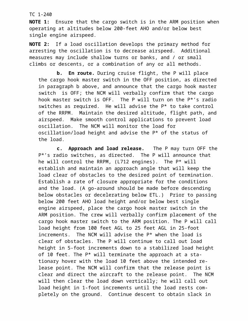
TC 1-240
HAL250 – 475
feet476 – 712
feet713 – 950
feet
VisibilityMinimum
(SM)1/2 3/4 1.0
Table 1. Effect of height above landing (HAL) surface elevation on visibility minimums.
c. Landing area sketch includes: A drawing/diagram of the landing area and the elevation of the highest obstacle within the landing area. It depicts the MAP in relation to the available landing area.
3. The space for notes directly below the minimum section will include waypoint names and coordinates.
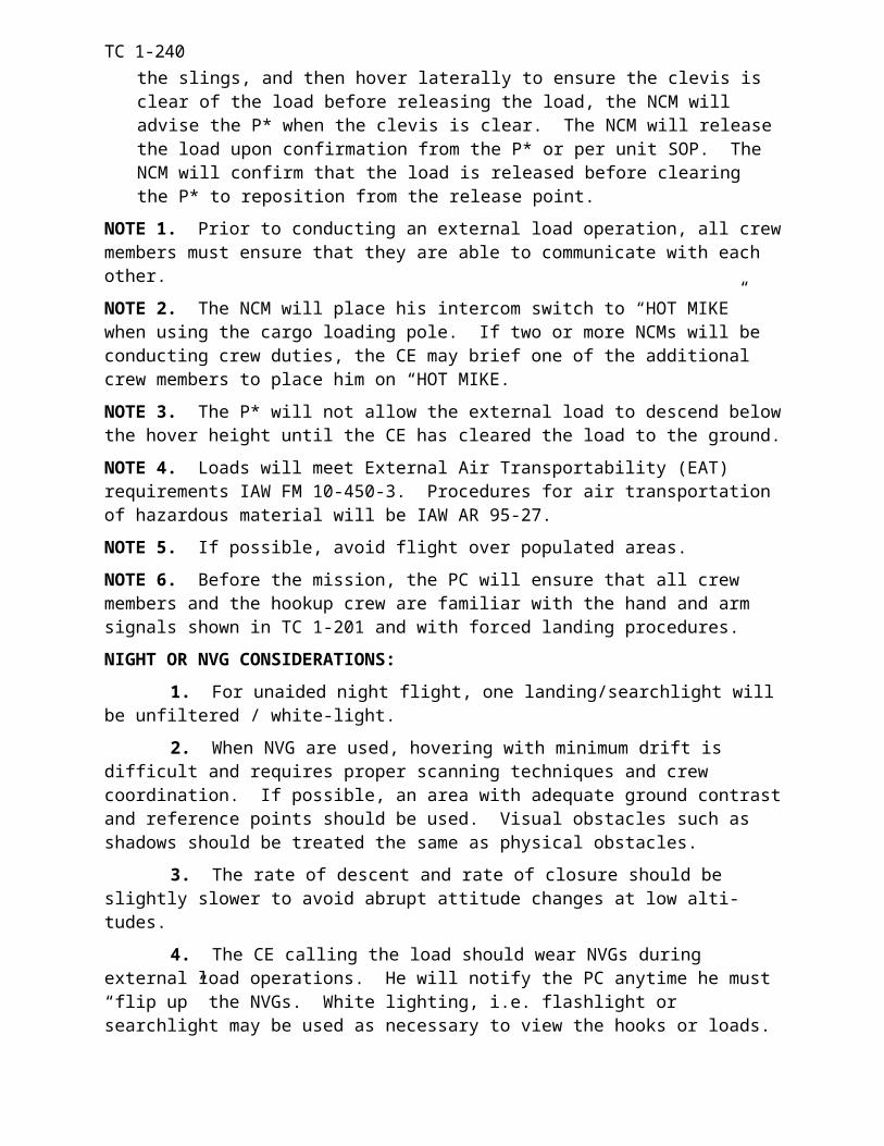
TC 1-240
Figure 4-7. Template for recovery procedure diagram.
APP CRS330
17 Mar 03 GPS 3302/52 Avn Bn. YOUR LZ, WHEREVER
LOA 300mm x 500mmTDZE 480Apt Elev 489
ATIS124.5234.5
APP CTL138.500245.300
MISSED APPROACH: Climb straight ahead to 3500 direct EAD WP and hold.
GROUND121.7257.8
UNICOM122.95
FOR VFR TRAINING and EMERGENCY USE ONLY!
LIMIT FINAL & MISSED APPROACH TO MAX 90 KIAS. PPS Required.
3500 EAD
(IAF) SOH N 09 23 40 W 100 00 06(FAF) DAK N 09 23 45 W 100 01 06(MAP) OTA N 0923 50 W 100 02 06
ELEV 489
CATEGORY COPTER
S-330 840 ½ 360 (400-½)
Sod Strip300m x 500m
90’ treesSurrounding LZ
Inverted Y
3 NM 3 NM
MAP
DAK
840
2200
SOH
3500
1027
(IAF)MOT
(IAF)WIL
(FAF)DAK
(MAP)OTA
(MAHF)EAD
1268
2046
MSA OTA 30 NM
3500(IF/IAF)SOH
SPECIAL AIRCREW TRAINING REQUIRED
TOWER119.35234.500
TDZE 480
FOR VFR TRAINING and EMERGENCY USE ONLY!
TC 1-240NOTE: The unit SOP will address the following topics; training requirements, procedure usage,
flight check, and periodic obstacle/diagram updates.
TRAINING AND EVALUATION REQUIREMENTS:
1. Training. Training may be conducted academically.
2. Evaluation. Evaluation may be conducted academically.
REFERENCES:Unit SOPFM 1-240FAA Handbook 8260.3 (TERPS Manual)FAA Order 8460.42A (Helicopter GPS Non-precision Approach Criteria)FAA Order 7130.3 (Holding)
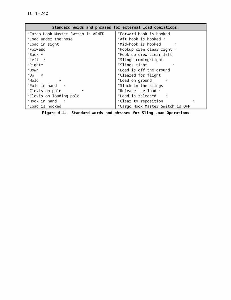
TC 1-240TASK 2052
Perform emergency GPS approach
CONDITIONS: In a CH-47 helicopter in VMC or simulated IMC, or in a CH-47FS, given an approved emergency GPS recovery procedure, with procedure clearance received and the before landing check completed.
STANDARDS: Appropriate common standards plus these additions/modifications:
1. Enter and/or confirm the appropriate waypoints (IAF, IF, FAF,MAP, MAHF) into the navigation system.
2. Execute the procedure IAW an approved recovery procedure.
3. Select an airspeed no greater than 90 KIAS on final and missed approach segments.
4. Maintain the prescribed course + 5 degrees.
5. Comply with the descent minimums prescribed for the procedure.
6. Arrive at the MDA prior to reaching the MAP.
7. Execute a missed approach upon reaching the MAP if a safe landing cannot be accom-plished.
8. During the missed approach, immediately establish a climb utilizing an appropriate rate of climb airspeed, until established at the MSA.
DESCRIPTION:
1. Prior to flight the crew should review the recovery procedure in conjunction with the map to familiarize themselves with the procedure, local terrain and obstructions in the vicinity of the procedure. The PC performs a thorough map reconnaissance to determine the highest ob-struction in the area of operations.
2. Prior to initiating the procedure, the P* must climb to the prescribed MSA, proceed to-ward the IAF, and make the appropriate radio calls. During the procedure, the P* will focus pri-marily inside the aircraft on the instruments. Adjust the aircraft ground track to cross the IAF, IF, and then the FAF on the prescribed course. When over the FAF, begin the final descent as appropriate.
3. The P remains primarily focused outside the aircraft to provide adequate warning for avoiding obstacles/hazards, and will announce when his attention is focused inside the cockpit. The P and NCM will monitor the aircraft instruments during the procedure and the P should tune the communication and navigation radios and transponder as required. The P will be prepared to call out the procedure to the P*, if asked, and be in a position to assume control of the aircraft and land the aircraft if VMC is encountered.
4. The NCM will position himself on the P* side of the aircraft for obstruction clearance and airspace surveillance. Alert the crew immediately if VMC is encountered.
NIGHT OR NVG CONSIDERATIONS. The P should be in a position to assume control of the aircraft at any time when a landing environment can be determined visually (aided/unaided). During night unaided flight, consider using the searchlight to identify the landing area.
TRAINING CONSIDERATIONS: This task will ONLY be performed under VMC or simu-lated IMC in a training environment.
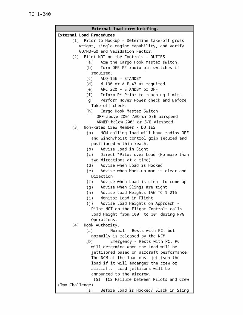
TC 1-240NOTE 1: The IAF, IF, FAF, MAP and MAHF must be programmed into the navigation system as an additional route for the mission.
NOTE 2: It is not necessary to hold after a missed approach. The PC may elect to return to the IAF at the MSA and attempt to complete the approach after coordination with ATC or with other aircraft utilizing the approach procedure.
NOTE 3: The AN/ARN-128B Doppler/GPS will not be used as the primary source of naviga-tion information for IFR operations in controlled airspace; however, its use should be considered and planned for as an emergency backup system.
NOTE 4. Inadvertent IMC multi-ship operations must be thoroughly briefed in the mission brief as a minimum on the following topics: individual aircraft holding altitudes/separation, when individual aircraft are allowed to depart their assigned altitude, missed approach procedure with aircraft in the holding pattern, frequencies, and command/control procedures.
TRAINING AND EVALUATION REQUIREMENTS:
1. Training. Training may be conducted in the aircraft or simulator.
2. Evaluation. Evaluation will be conducted in the aircraft or simulator.
REFERENCES: Appropriate common references plus the following:
Unit SOP
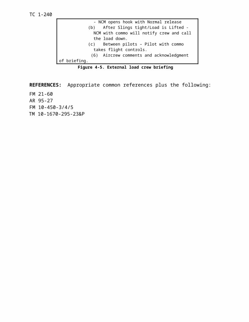
TC 1-240TASK 2053
Perform water-bucket operations
WARNING
Never dump water onto ground personnel as the water impact could result in injury.Minimize hovering or flying slowly over fires. The rotor-wash fans the flames which may cause more hazards to ground crews. When performing this task with cabin doors open, ensure that any personnel in the cabin area are wearing a safety harness secured to a tie-down ring or are seated in a seat with seat belt on.
NOTE
The water bucket, when loaded is a high-density load with favorable flight characteris-tics. Reduced Vne and bank angle limits must be kept in mind. Much of the mission profile is flown at high gross weight and low airspeed. In addition, density altitude is greatly increased in the vicinity of a major fire. Performance planning must receive special emphasis.
CONDITIONS: In a CH-47 helicopter with an operational cargo hook, water bucket, required briefings, checks completed, and an Air Worthiness Release.
STANDARDS: Appropriate common standards plus these additions/modifications:
1. Rated
a. Conduct permission planning to determine fuel and bucket cinching requirements. Verify the aircraft will remain within gross weight and CG limitations for the duration of the flight.
b. Conduct a thorough crew briefing.
c. In conjunction with the NCM(s), complete the required checks to ensure proper sys-tem operation prior to mission departure.
d. Operate the water bucket system per manufacture specifications.
e. Recognize and respond to a water bucket system malfunction.
f. Use proper dipping procedures for the water bucket type.
g. Demonstrate knowledge of fire behavior and terminology.
h. Hook-up and hover:
(1) Maintain vertical ascent heading ±10°.
(2) Maintain altitude of load 5 feet AGL, +1 foot.
(3) Complete hover power and go-no-go checks.
i. Enroute: Maintain load obstacle clearance (minimum 50 feet AHO).
j. Approach and water release:
(1) Evaluate fire/simulated fire for flight path and altitude requirements.
TC 1-240(2) Maintain a constant approach angle to ensure load safely clears obstacles.
(3) Maintain ground track alignment with selected approach path.
(4) Execute a smooth and controlled pass or termination over the intended point/area of water drop.
k. Deploy water as directed in proper location, orientation, and/or length.
2. Nonrated.
a. In conjunction with the rated crewmember(s) complete required water bucket checks to ensure proper system operation prior to mission departure and attach water bucket to the air-craft.
b. Ensure water bucket is configured for the condition and mode of flight.
c. Recognize and respond to a water bucket system malfunction.
d. Demonstrate knowledge of fire behavior and terminology.
DESCRIPTION:
1. Crew actions:
a. The PC will conduct a thorough crew, external load, and water bucket briefing and ensure all crewmembers are familiar with water bucket operations, emergency, and communication procedures. He will ensure that DD Form 7382-R has been completed. He will confirm that required power is available by comparing the information from the PPC to the hover power check.
b. The P* will remain primarily focused primarily outside the aircraft throughout the maneuver. He will monitor altitude and avoid obstacles.
c. The P will monitor the cockpit instruments and assist the P* in clearing the air-craft. He will set cargo hook switches, as required, and should make all radio calls. When directed by the P* during the approach, the P will place the cargo hook arming switch to the ARMED position. The NCM will release the water IAW with the crew briefing.
d. The P and NCM will assist in clearing the aircraft and will provide adequate warning of obstacles. They will announce when their attention is focused inside and again when attention is reestablished outside
e. The NCM will remain primarily focused on the bucket. He will guide the P* during the bucket pickup, advise of the bucket condition in flight, provide directions and as-sistance when to dump the water, and direct the P* when setting down the bucket.
f. The NCM will advise the P* of any water bucket faults or failures.
g. External load procedures IAW Task 1063 will be used for normal external load techniques and load call outs, the NCM will advise the P* when the water bucket is in the water, filling, full, water deploying and empty. He will instruct the P* as necessary to keep the electrical attachment assembly from entering the water.
2. Procedures.
a. Preflight:
(1) The PC will analyze the mission using METT-T and determine the amount of wa-ter required to conduct the mission and the initial profile to be used during the water emplace-ment.
TC 1-240(2) The NCM(s) will ensure the water bucket is installed, all installation checks are
completed IAW unit SOP.
(3) The crew will conduct the ground checks IAW manufacture procedures to con-firm the proper operation of the water bucket before takeoff.
b. Hook-up and hover: Once the water bucket is placed on the ground beside the air-craft and all associated wiring is installed, place the cargo release switch in the ARM position. Follow verbal signals from the NCM to hover over the water bucket. Apply control move-ments as necessary to remain vertically clear and centered over the water bucket. Once in this position, smoothly apply thrust input until all slack is removed from the suspension cable. Maintain heading with pedals. Apply additional thrust to raise the bucket to 10 feet AGL. Monitor aircraft instruments to ensure aircraft limitations are not exceeded.
c. Water pick-up: Evaluation of the water pick-up should include depth, obstacles, water current and availability of hover references.
(1) Bambi Bucket Water Pick-up. Arrive over water source with no forward ground speed and a bucket height of 10 feet above water level. Slowly reduce the thrust and ap-ply a slight amount of forward cyclic until the Bambi bucket contacts the water. Then follow the verbal signals of the NCM to remain centered over the bucket as it fills, applying cyclic, thrust, and pedals as necessary. The pilot can vary the bucket’s capacity by varying the speed at which it is pulled from the water. A slow lift gives minimum fill. A fast lift gives maximum fill. When the NCM indicates the bucket is ready, or full, increase the thrust lever until all slack is re-moved from the suspension cable and the lip of the bucket is clear of the water, maintain heading with pedals. Apply additional thrust to raise the filled bucket clear of the water’s surface to a height of 10 feet. Ensure the bucket is holding the water and monitor aircraft instruments to en-sure aircraft limitations are not exceeded.
(2) Sims and Simplex Water Pick-up. Arrive over water source with no forward ground speed and a bucket height or 10 feet above water level. Ensure bucket doors are open. Slowly reduce the thrust until the bucket makes contact with the water. Once the bucket has sub-merged in the water, follow the verbal signals from the NCM to remain centered over the bucket as it fills applying cyclic, thrust, and pedals as necessary. When the NCM indicates the bucket id full, he will close the bucket doors and ensure the bucket is ready, then the P* can increase the thrust until all slack is removed from the suspension cable and the lip of the bucket is clear of the water. Maintain heading with pedals. Apply additional thrust to raise the filled bucket clear to the water’s surface to a height of 10 feet. Ensure the bucket is holding the water and monitor air-craft instruments to ensure aircraft limitations are not exceeded.
NOTE: Use the manufactures recommended enroute airspeeds for each type of water bucket. This prevents the buckets from twisting and pinching the cables.
d. Takeoff: Establish a constant angle of climb that will permit safe obstacle clearance. When above 100 feet AGL or when clear of obstacles, adjust attitude and power as required to establish the desired rate of climb and airspeed. Smoothly adjust flight con-trols to prevent bucket oscillation.
NOTE: Ensure that the cargo hook-arming switch is in the ARMED position when operating at altitudes below 300-feet AHO and in the SAFE position above 300-feet AHO.
e. Enroute: Maintain the desired altitude, flight path, and airspeed. Make smooth control applications to prevent bucket oscillation. If an oscillation occurs, perform the same procedures as in Task 1063 External Load Operations.
TC 1-240f. Approach and water release: The PC will determine the most appropriate
height and speed for the pattern desired or IAW the mission briefing. Evaluation of the fire should include wind direction, velocity, terrain, and type of fire. Fires usually require a drop height of 100-200 ft AGL and a ground speed of 30-60 kts. The aircraft’s ground track should be upwind and adjusted so that the spray will provide maximum cooling to hot spots as well as dampen unburned vegetation. Altitude and airspeed may be adjusted for fires of varying intensity and types; however, it must be noted that low, slow passes may tend to in-crease the fire’s intensity due to rotor down wash. When the approach angle is intercepted, decrease the thrust lever to establish the descent. When passing below 300 feet AGL, place cargo hook in ARM position. When reaching the desired airspeed and altitude the recom-mended crew coordination terms for bucket operations are as follows:
(1) Approaching the target = “Prepare to open the doors” (Approximately 10 seconds out).
(2) Over the target = “Open doors”
(3) When the drop is complete = “Close doors”
NOTE 1. The NCM will advise the P* the condition of the bucket and call out the water level while releasing water. The bucket manufacturer does not recommend dumping at airspeeds above 50 KIAS.
NOTE 2. There is a delay of appropriately 0.5 to 1.0 second between the activation of the dump switch and discharge of the water.
NOTE 3. Avoid flight over populated areas.
NOTE 4. A go-around should also be initiated if visual contact with the water release area is lost or any crewmember announces “climb, climb, climb”. This phrase will only be used when there is not enough time to give detailed instructions to avoid obstacle.
NOTE 5. Table 4-7 is a sample water bucket procedure guide for water bucket operations to include sample calls for dropping water.
g. Post mission:
(1) Ensure water bucket is serviceable.
(2) De-rig aircraft and water bucket. Ensure all documentation is complete on water bucket usage and inspection.
SAND/DUST/SMOKE CONSIDERATIONS: If during the approach, visual reference with the water release area or obstacles is lost, initiate a go-around or ITO as required, immediately. Be prepared to transition to instruments. Once VMC is regained, continue with the go-around. (If required, releasing the water reduces the GWT of the aircraft and minimizes power demand).
MOUNTAINOUS AREA CONSIDERATIONS: If at any time during an approach, insuffi-cient power is available or turbulent conditions or wind shift create an unsafe condition, perform a go-round immediately. (If required, releasing the water reduces the GWT of the aircraft and minimizes power demand).
OVERWATER CONSIDERATIONS: All crewmembers will wear floatation devices IAW AR 95-1. Over-water flight, at any altitude, is characterized by a lack of visual cues, and, there-fore, has the potential of causing visual illusions. Be alert to any unannounced changes in the flight profile and be prepared to take immediate corrective actions. The radar altimeter low bug should be set to assist in altitude control. Operations become increasing more hazardous as refer-ences are reduced (open water verses a small lake), water state increases (calm to chop to break-
TC 1-240ing condition with increasing wave height), and visibility decreases (horizon becomes same color as water, water spray or rain on windshield, sunny mid-day vs. twilight).
NOTE: There is a high probability the Doppler (AN/ASN-128) MEM indicator lamp will light while flying over smooth water. However, if the lamp remains on for over 10 minutes, over land or rough water, there is a malfunction in the Doppler set.
NIGHT OR NVG CONSIDERATIONS: Not Recommended.
1. During water bucket operations the P*’s attention will be divided between the aircraft in-struments (altitude and ground speed) and the outside. It is critical during NVG operations that the crew members focus be primarily outside to provide warning to the P* of obstacles or haz-ards during the entire operation.
2. Spatial disorientation can be overwhelming during over water operations at night. Proper scanning techniques are necessary to avoid spatial disorientation.
TRAINING AND EVALUATION REQUIREMENTS:
1. Training. Training will be conducted in the aircraft.
2. Evaluation. Evaluation will be conducted in the aircraft.
REFERENCES: Appropriate common references plus the following: Water Bucket Air Worthiness ReleaseFM 55-450-1AR 70-62FM 20-32
WATER BUCKET PREFLIGHT CHECK1. Bottom of chain for tears in fabric.2. Shackle and lockwire or tie-wrap condition.3. Sidewall battens.4. Diagonal M-straps connecting the suspension cables for wear.5. Purse lines on the fabric dump valve.6. Cinch strap belt – end opposite the D-ring shall have a knot.7. Suspension lines for frays, kinks and conditions.8. Ballast pouch in the bucket for rips or holes.9. Control head for secure fittings.10. Tripline for kinks, frays, or loose swages.11. Perform operational check of control head.DUMPING WATER1. Pilot calls: Altitude, airspeed, and monitors radar altimeter during pass.2. NCM: (Approximately 10 seconds from target) calls “Prepare to open bucket/doors”.3. NCM: Calls over target “Open bucket/doors”.4. NCM responds: “Bucket/doors open, bucket is ¾, ½, ¼, bucket empty.” Water bucket doors as required (open or closed depending on type of bucket and clear for flight.LANDING1. Normal load approach.2. Clear bucket to ground.3. Clear to slide (direction) away from load.4. Release the slings and disconnect electrical lines.5. Recover bucket and secure in aircraft.EMERGENCY PROCEDURES1. Open the bucket: IF NECESSARY.2. Call bucket open – bucket empty3. Jettison the load: IF NECESSARY4. Call – load jettisoned.5. Hook Operations – Normal and Emergency.6. Lost Commo procedures.
TC 1-240Table 4- 8. Water bucket procedure guide
TASK 2054Perform Fast-Rope Insertion and Extraction (FRIES)
WARNING
Ensure that crewmembers in the cabin area are wearing a safety harness secured to a tiedown ring anytime the door or ramp is open. Also, ensure that all ropers are on the ground before any ropes are released.
CONDITIONS: In a CH-47 helicopter with FRIES equipment installed.
STANDARDS: Appropriate common standards plus these additions/modifications:
1. Rated.
a. Conduct a thorough crew and passenger briefing.
b. Maintain entry altitude as directed ±10 feet.
c. Maintain entry airspeed of 80 KIAS ±5 KIAS.
d. Maintain track aligned with landing direction.
e. Perform a smooth, controlled termination to a hover over the insertion point. Decel-eration attitude not to exceed 20 degrees.
f. Maintain appropriate hover height ±5 feet (not to exceed rope height).
2. Nonrated. Ensure that the aircraft is configured for FRIES operations per TC 21-24.
DESCRIPTION:
1. Crew actions.
a. The PC will conduct a crew and passenger briefing and ensure personnel are fa-miliar with normal and emergency procedures. He will ensure the aircraft is rigged.
b. The P* will remain focused primarily outside the aircraft throughout the ma-neuver and will announce when he begins the maneuver. The P* will also announce the in-tended point of insertion.
c. The P and NCM will assist in clearing the aircraft, and will provide adequate warning of obstacles. They will also assist the P* in maintaining a stable hover. The NCM will inspect the rigging to ensure that the aircraft is configured for fast rope operations.
2. Procedures.
a. To perform a FRIES assault, execute a VMC approach to the insertion point. On final, adjust airspeed and altitude during the approach to stop over the insertion point at a predetermined hover height (not to exceed rope length). At a stabilized hover, the FRIES operation begins. Remain over the area at a stabilized hover until all ropers and ropes are clear.
b. After ropers are clear, crewmembers will pull the ropes back inside the aircraft or release them by pulling the locking device and detaching the rope. Keep the aircraft sta-tionary until the "ropes clear" signal is given.
TC 1-240NOTE 1. Tasks 1038, Perform hovering flight, and 2036, Perform terrain flight deceleration, contain procedures that may be used in performing this task.
NOTE 2. A high hover, especially if a 90-foot rope is used, may cause the loss of all visual hover cues.
NOTE 3. Figure 4-9 is a sample FRIES checklist.
NIGHT OR NVD CONSIDERATIONS: Due to loss of forward references during decelera-tions, recommend maximum pitch attitude of 15 degrees. Use IR bypass band filter searchlight as necessary to maintain position and hover altitude for NVG operations. Proper scanning tech-niques are necessary to detect aircraft drift and to avoid spatial disorientation.
TRAINING AND EVALUATION REQUIREMENT:
1. Training. Training will be conducted in the aircraft.
2. Evaluation. Evaluations will be conducted in the aircraft.
REFERENCES: Appropriate common references plus:
FRIES Air Worthiness Release.TC 21-24
Headquarters, Department of the Army (HQDA) policy specifies that FRIES is not approved for Army-wide use and names the Commanding General, United States Army Special Operations Command (CG USASOC) as the executive agent for FRIES doctrine. The use of FRIES is restricted to special operations forces, pathfinders, long-range surveillance units, and HQDA-approved schools with an USASOC-approved FRIES program on instruction. Request for other units to conduct FRIES operations will be submitted to Commander, USASOC, ATTN: AOOP-TRS, Fort Bragg, NC.
TC 1-240
Fast-Rope Operations Checklist
Pre-Roping Actions
Receive a briefing from the OIC or the AMCCoordinate and brief all participants.Rig aircraft and conduct a joint inspection.Brief roper, AFRMs, and safeties.Rig and inspect ropers.Conduct a static rehearsal.
Aircraft LoadingPosition equipment and personnel.Make sure all personnel have straps or seat belts.
Actions in FlightMonitor the command net.Monitor the aircrew net.Monitor the flight route.
Actions at 10-Minute Warning (applies to long infiltration’s)Issue the 10-minute time warning and GET READY.Check equipment and belay system hookup.Check fast-rope hookup.Secure fast-rope bar in position.Make sure rope is back coiled and markers are attached.
Actions at 6-Minute WarningIssue the 6-minute warning.Remove personnel restraints or seat belts.Position personnel and equipment.Break chemlights (night operations).Open aircraft doors, if required.
Actions at 1-Minute WarningIssue the 1-minute time warning and STAND BY.Position ropers in stick formation.
Actions at FlareIdentify the target area.Deploy bundles/equipment (Safeties) and clear ropes.Deploy FRIES ropes (FRM and AFRM).Check ropes to make sure 15 feet of rope are on the surface (FRM).
Actions for DescentFRM, AFRM, or safety positions the number 1 man at the rope. (The FRM
may exit first or last).FRM issues the command GO. AFRM echoes GO command, and the ropers
exit the aircraft.Safety informs the PC, “ROPERS OUT.”AFRM or safety controls the rate of exit of the ropers.AFRM exits last.Aircrew or safeties observe the last roper. Safety tells the PC, “ALL ROPERS
AWAY,” after the last roper is on the surface and signals.PC issues command JETTISON or RECOVER ROPES.Aircrew or safety jettison or recovers ropes, and issues ROPES CLEAR
report to the PC.
Figure 4-9. Fast Rope Operations Checklist
TC 1-240TASK 2056
Perform rappelling operations
WARNING
Ensure the rappel master secured to a tie down ring. Also ensures that all ropers are on the ground before any ropes are released. If the roper’s equipment becomes fouled on the ramp or probe, ensure the roper is “locked in” on the rope prior to freeing the equipment. Maintain visual contact with the roper until equipment is freed.
CAUTION
Weight bags must remain attached to any rope that is retrieved into the aircraft.
CONDITIONS: In a CH-47 properly configured and hover OGE power is available.
STANDARDS: Appropriate common standards plus these additions/modifications:
1. Rated.
a. Conduct a thorough crew and passenger briefing.
b. Maintain appropriate hover altitude ± 5 feet.
c. Maintain ropes in continuous contact with the ground.
d. Do not allow drift to exceed 5 feet from the intended hover point.
e. Hover Symbology selected at P* station.
2. Nonrated.
a. General Duties.
(1) Properly clear aircraft and make rope calls informing pilots of status of ropes and passengers.
(2) Check all equipment is properly installed.
(3) Ensure load/passengers weight don’t exceed aircraft limitations.
(4) Ensure equipment is properly rigged when performing equipment drops.
(5) Ensure ropes are on ground prior to releasing ropers.
(6) Utilize proper terminology.
DESCRIPTION:
NOTE: The PC will ensure that the intended P* for the maneuver is assigned the appropriate seat position that will afford the greatest visibility for conducting the maneuver.
1. Crew Actions.
a. PC conducts or directs a crew member to conduct a crew and passenger briefing and ensure personnel are familiar with normal and emergency procedures. NCM will verify rope
TC 1-240lengths with supportive unit and inform the PC. NCM will inspect rigging to ensure that the aircraft is properly configured for rappeling operations. PC confirms the ropes are properly rigged.
b. P* remains focused primarily outside the aircraft throughout the maneuver and will announce when he begins the maneuver. P* will also announce the intended point of insertion and pass the rappelling execution command to the NCMs.
c. P and NCM assist in clearing the aircraft, and provide adequate warning of obstacles. They will also assist P* in maintaining a stable hover.
d. NCMs will determine who will make specific calls, and inform the pilots (Right Ramp normally makes primary calls.) NCMs will be responsible for passing the 10, 6, 3 and 1-minute calls. The Right Ramp usually will be responsible for making the primary rope calls.
e. NCMs will use pre-established procedures and communications including hand and arm signals with the fast rope master. NCMs will deploy, release, or retrieve the ropes.
f. NCMs will inform PC once all ropes are clear of the aircraft, or once ropes have been retrieved back into the aircraft, or ropes are secure during elevator training.
2. Procedures.
a. Ten (10) minutes prior to ETA the P will announce, “TEN MINUTES OUT.” Each NCM or rope master (RM) will inform the pax at his station of the timed call and announce when his station is ready, “AFT READY,” “FWD READY.” The same procedures will be conducted at the six (6) minute, three (3) minute and one (1) minute timed calls. At night the NCMs at each station will break the chemlights attached to the ropes by the six (6) minute call.
b. When the objective is sighted and the P* judges that he can initiate the maneuver to stop at a stabilized hover over the target point, the P* will apply aft cyclic and adjust thrust as necessary to stabilize at a hover over the intended target. If the closure rate to the intended hover point is too fast, the P* may adjust the aircraft attitude, but will not exceed twenty (20) degrees nose high. Maintain appropriate roping height 5 feet. The P should call out aircraft parameters; attitude and radar height during the maneuver. NCMs will get into roping position by one (1) minute out.
c. When stabilized at a hover, the Right Ramp should announce “OVER THE TARGET,” the P* will call “ROPES, ROPES, ROPES.” The NCM at each station will deploy, direct or help ropes; when the ropes have been deployed, the Right Ramp should announce “AFT ROPES OUT” (if applicable) the Right Gun will announce “FWD ROPES OUT” (if applicable) when personnel/equipment exits the aircraft, the Right Ramp should announce, “AFT ROPING IN PROGRESS,” the FWD CE will announce “FWD ROPING IN PROGRESS” (if applicable). Although All NCMs are responsible for maintaining the aircraft at a stabilized hover with minimum drift, and clear of obstructions, the Right Ramp should make the primary calls.
d. When personnel/equipment are clear, each NCM at a station will visually confirm personnel/equipment are clear and release or retrieve ropes as briefed. The Right Ramp should announce, “AFT ROPES RELEASED, AFT READY,” the Right Gun will announce, “FWD ROPES RELEASED (if applicable), FWD READY, CLEARED FOR FLIGHT.”
e. The P* will announce his intent to depart the target area. He will maintain outside visual reference and depart the area maintaining obstacle clearance along his intended ground track.
TC 1-240f. Standard terminology will be used during rappelling insertion (see Figure 4-10).
“*Ropes, ropes, ropes” From P* to crew, indicates ready for rope deployment.
“*Ropes out” From FE/CE to pilots, indicates ropes are deployed over target.
“*Roping in progress” From FE/CE to pilots, indicates first roper is exiting aircraft.
“*Ropes released” From FE/CE to pilots, indicates ropes have been cut away.
“*Ropes retrieved” From FE/CE to pilots, indicates ropes have been pulled back into aircraft and are secured.
“Hold” From FE/CE to pilots, hold position.
“Move” (left, right, fwd, back) From FE/CE to pilots, indicates direction in which to reposition aircraft.
“Aft ready, fwd ready” From FE/CE to pilots, indicates all ropers are clear from air craft.
“Clear for flight” CLEAR FOR FLIGHT will only be used by the FWD CE
“Stop stick” From FE/CE to pilots, indicates a problem at a station, all roping ceases until problem is rectified.
“Over the target” From FE/CEs to Pilots, indicates Acft is over the target.
* Aft, Forward from CE to pilots, will preclude calls to indicate appropriate station.
Figure 4-10. Standard Rappelling Insertion Terminology
TRAINING AND EVALUATION REQUIREMENTS:
1. Training. Training will be conducted in the aircraft.
a. Pilot training does not require ropers.
b. NCM training requires personnel/gear to go down the ropes.
2. Evaluation. Evaluation will be conducted in the aircraft.
a. Pilot evaluations do not require ropers.
b. NCM evaluations require personnel/gear to go down the ropes.
REFERENCES: Appropriate common references.
TC 1-240TASK 2058
Perform special patrol infiltration/exfilitration (SPIES)
WARNING
Ensure that the SPIES master and crew chief wear a safety harness secured to a tiedown ring anytime door or ramp is opened.
CAUTION
Ensure that SPIES rope remains secured to the cargo hook until the aircraft has landed. If recovery of SPIES rope is impossible, execute a roll-on landing to avoid entanglement in the rotor system.
CONDITIONS: In a CH-47 helicopter with SPIES equipment installed and SPIES crew as-signed.
STANDARDS: Appropriate common standards plus these additions/modifications:
1. Rated.
a. Conduct a thorough crew and passenger safety briefing.
b. Maintain obstacle clearance between team members, obstacles, and the ground.
c. Maintain airspeed ± 5 knots. (Maximum airspeed with team members attached is 70 KIAS in moderate climates and 50 KIAS in cold climates).
d. Bank angle not to exceed 30 degrees.
2. Nonrated. Ensure that the aircraft is prepared for SPIES operations per TC 21-24 and the unit SOP.
DESCRIPTION:
1. Crew actions.
a. The PC will conduct a thorough crew briefing and ensure all crewmembers are fa-miliar with SPIES operations, emergency, and communication procedures. He will ensure the aircraft is rigged.
b. The P* will remain focused primarily outside the aircraft throughout the maneuver for aircraft control and obstacle avoidance. He will announce the intended point of extraction and remain centered over the target with corrections from the SPIES master as required.
c. The P and NCM will assist in clearing the aircraft and will provide adequate warn-ing of obstacles. They will assist the P* during the pickup phase of the operation. They will advise the P* when the slack is out of the ropes and when the SPIES members are off the ground and above the highest obstacle. During forward flight, the NCM must constantly moni-tor the SPIES members and keep the P* informed of their stability and clearance.
TC 1-2402. Procedures.
a. Establish communications with personnel at extraction site. The approach should be terminated into the wind at a 90-foot hover. Normal length of SPIES ropes is 120 feet. Once stabilized over the extraction site, the NCM when authorized by the PC will throw out the de-ployment bags. The NCM will inform the P* when all ropers are ready and hook-up is com-plete. The NCM verifies that extraction harnesses are secure and safe as the ropers are lifted off the ground.
b. Ascend at a rate that will ensure the safety of the SPIES members. To avoid "jerk-ing" the SPIES members off the ground, the slack in the ropes must be removed cautiously. Do not start forward flight until all obstacles are cleared.
c. Maximum en route airspeed will be no faster than 70 KIAS in moderate climates and 50 KIAS in cold climates while team members are attached to the SPIES rope. Maximum aircraft bank angle will be no greater than 30 degrees. During forward flight the NCM must constantly monitor the SPIES members and keep the P* informed of their stability. In may be necessary to reduce airspeed if SPIES personnel begin to spin, or if the cone angle exceeds 30 degrees.
d. Upon arrival at the dismount area, a transition is made into hovering flight at an alti-tude of 250 feet AGL. A vertical descent is started with the rate not to exceed 100 foot per minute (at touchdown). Maintain a stable hover until SPIES team members clear the rope.
WATER EXTRACTION CONSIDERATIONS:
1. The SPIES is suitable for extracting teams from the water. For this procedure three in-flatable life vests or any type of floatation device is tied to the SPIES rope to provide buoyancy for the rope while in the water.
2. Takeoff, en route, and landing are the same as over land. The dismounting procedures differ when landing on a ship. Once on board, the team members take their orders from personnel in charge of the deck.
NIGHT OR NVG CONSIDERATIONS:
1. For unaided night flight, the landing light and searchlight should be operational. If an NVG filter is installed, it should be removed.
2. Due to the high hover altitude of SPIES operations, it is very difficult to determine alti-tudes and relative position over the ground. The barometric altimeter is not reliable for this maneuver, but can be used as an aid to help maintain a constant altitude. References, such as tops of trees, lights, and man made objects can be used to help prevent drift by lining up the objects and maintaining their relative position once the aircraft is at a stable altitude.
3. If possible, select an area with good contrast and several reference points at the same or greater height as the SPIES hover altitude. Proper scanning techniques are necessary to avoid spatial disorientation.
4. Spatial disorientation can be overwhelming during over water operations at night. If there are visible lights on the horizon or if the shoreline can be seen, the pilot may opt to approach the survivor(s), so the aircraft is pointed toward these references, if the wind permits. If no other references exist, deploy chemlights to assist in maintaining a stable hover.
TC 1-240TRAINING AND EVALUATION REQUIREMENTS:
1. Training. Training will be conducted in the aircraft.
2. Evaluation. Evaluation will be conducted in the aircraft.
REFERENCE: Appropriate common references plus the SPIES Air Worthiness Release.
TC 1-240TASK 2059
Perform rescue-hoist/winch operations
WARNING
Ensure that crewmembers in the cabin area are wearing a safety harness secured to a tiedown ring anytime the upper cabin door and rescue hatch door are open. The crewmember riding the hoist will be secured either to the aircraft or to the jungle penetrator. Ensure cable touches the ground or the water before ground personnel touch the cable. Cable will be charged with in excess of 300,000 volts of static electricity.
CAUTION
Care must be taken not to snag terrain features or foliage with the rescue hoist cable. This may result in exceeding the 600lb structural limitation of the overhead pulley support.
CONDITIONS: In a CH-47 helicopter equipped with a rescue-hoist/winch system.
STANDARDS: Appropriate common standards plus these additions/modifications:
1. Rated.
a. Conduct a thorough crew and passenger safety briefing.
b. Perform rescue-hoist procedures per TM 1-1520-240-10/CL.
c. Perform rescue-hoist/winch procedures per TMs 1-1520-240-10/CL, FM 8-10-6, TC 1-201, and the unit SOP.
d. Maintain appropriate hover altitude ±5 feet.
e. Do not allow drift to exceed ±5 feet from the intended hover point.
2. Nonrated.
a. Perform a preflight inspection of the rescue hoist/winch per TM 1-1520-240-10/CL and the unit SOP.
b. Ensure that the crew, passengers, cargo, and mission equipment are secured.
c. Operate the rescue-hoist/winch.
DESCRIPTION:
1. Crew actions.
a. Rescue Hoist Operations
(1) The PC will conduct a thorough crew briefing and ensure all crewmembers are familiar with rescue-hoist operations, emergency procedures, communication procedures, lower-ing the flight medic, and lifting the patient of the ground using the hoist or aircraft. He will also ensure that all crewmembers understand “CUT CABLE” procedures.
(2) The P* will remain focused primarily outside the aircraft throughout the maneu-ver for aircraft control and obstacle avoidance. He will announce the intended point of hover and remain centered over the target with corrections from the NCM.
TC 1-240(3) The P and NCM will assist in clearing the aircraft and will provide adequate
warning of obstacles. They will also assist the P* in maintaining a stable hover by providing the P* with information regarding the drift of the aircraft. The P will also monitor cockpit indica-tions. The P will be able to operate the control panel for the rescue hoist if necessary.
(4) The NCM will ensure that the hoist is configured and will ensure that all lifting devices (i.e. Jungle penetrator, SKED/Stokes litter, and survivor’s slings) are secured in the air-craft before takeoff.
(5) NCM ensure the winch is configured for rescue hoist operations and the appropri-ate write-up is entered on the DA Form 2408-13-1 for the mid hook being removed IAW TM 1-1520-240-10.
(6) The NCM conduct the hoist operation per TC 1-201, TM 1-1520-240-10/CL, and the unit SOP.
b. Cargo Winch Operations
(1) NCM ensure the winch is configured for rescue hoist operations and the appropri-ate write-up is entered on the DA Form 2408-13-1 for the mid hook being removed IAW TM 1-1520-240-10.
(2) The NCM conduct the rescue-hoist operation per TC 1-201, TM 1-1520-240-10/CL, and the unit SOP.
2. Procedures.
a. General Recovery Procedures Over Land. Crewmembers alerted approxi-mately 5 minutes prior to arrival at pickup site. Crewmembers complete all required checks (i.e. Rescue Hoist Control Panel switches set, Hoist circuit breakers set, ICS selector switches set, and crewmembers reposition for hoist operations). Make the approach into the wind if possible and plan to terminate the approach at an altitude that will clear the highest obstacle. Select an appropriate reference point to maintain heading and position over the ground. Once stabilized over pickup site perform hoist operations IAW FM 8-10-6, TC 1-201, TMs 1-1520-240-10/CL, and the unit SOP.
b. Inert Patient Recovery. General format is the same as over land except: The NCM/MO is lowered on the hoist and secures the patient to the recovery device. Prior to deploying, all crewmembers will be briefed on method of recovery (simultaneous or singu-lar recovery of the patient and MO) and a radio communications check should be made be-tween the pilot and NCM/MO.
c. General Recovery Procedures Over Water. General format is the same as over land except: A smoke device may be used to determine wind direction and velocity; terminate the approach at a 100 foot hover, 20 feet prior to reaching the patient; deploy the recovery device and allow to contact the water before reaching the patient. All crewmem-bers will wear floatation devices. Operations become increasing more hazardous as refer-ences are reduced (open water verses a small lake, or ship verses small boat), sea state in-creases (calm to chop to breaking condition with increasing wave height), and visibility de-creases (horizon becomes same color as water, water spray or rain on windshield, sunny mid-day vs. twilight).
TC 1-240NOTE: The NCM will advise the P* when the person/equipment is in position on the jungle penetrator. The NCM will perform hoist operations IAW the standard words and phrases IAW unit SOP. The NCM will secure jungle penetrator or stokes litter upon completion of the hoisting operation. Should difficulty in maintaining a stable hover occur, the NCM will extend additional cable as “slack” to preclude inadvertent jerking of the cable.
NIGHT OR NVG CONSIDERATIONS: Use proper scanning techniques to avoid spatial dis-orientation.
1. For unaided night flight, the landing light and searchlight should be operational. If an NVG filter is installed, it should be removed.
2. When NVGs are used, hovering with minimum drift is difficult and requires proper scan-ning techniques and crewmember coordination. If possible, an area with adequate ground con-trast and reference points should be used.
3. Visual obstacles such as shadows should be treated the same as physical obstacles.
4. Spatial disorientation can be overwhelming during over water operations at night. If there are visible lights on the horizon or if the shoreline can be seen, the pilot may opt to approach the survivor(s), so the aircraft is pointed toward these references, if the wind permits. If no other ref-erences exist, deploy chemlights to assist in maintaining a stable hover.
TRAINING AND EVALUATION REQUIREMENTS:
1. Training. Training will be conducted in the aircraft.
2. Evaluation. Evaluation will be conducted in the aircraft.
REFERENCES: Appropriate common references plus the following:
FM 8-10-6TM 55-4240-284-12&P
TC 1-240TASK 2064
Perform paradrop operations
WARNING
Ensure that any personnel in the cabin area not wearing a parachute are wearing a safety harness secured to a tie- down ring or are seated in a seat with seat belt on.If parachutes use automatic ripcord releases, ensure that the automatic release is disconnected before descent is initiated. For an in flight emergency, if altitude can not be maintained, notify the jumpmaster immediately so automatic ripcord releases can be disconnected. Ensure that static lines remain secured to the anchor point until they are recovered or the aircraft has landed. If recovery of static lines is impossible, execute a roll-on landing to avoid entangling deployment bags in the rotor system.
CONDITIONS: In a CH-47 helicopter with a jumpmaster.
STANDARDS: Appropriate common standards plus these additions/modifications:
1. Rated.
a. Conduct a thorough crew and passenger safety briefing.
b. Maintain airspeed of no less than 80 KIAS and no more than 110 KIAS (with 90 KIAS being the optimum speed).
c. Maintain appropriate ground track over the drop zone.
2. Nonrated. Ensure that the aircraft is prepared for paradrop operations per TM 1-1520-240-10, FM 31-19, FM 57-220, and the unit SOP.
DESCRIPTION:
1. Crew actions.
a. The PC will conduct a thorough crew briefing and ensure all crewmembers are familiar with paradrop operations, emergency, and communication procedures. He will en-sure the aircraft is rigged.
b. The P* will remain focused primarily outside the aircraft throughout the ma-neuver.
c. The P and NCM will assist in clearing the aircraft and will provide adequate warning of obstacles and traffic.
d. The P will ensure that the jumpmaster or crew chief retrieves the static lines as soon as the last parachutist has cleared the aircraft.
e. The NCM will ensure that the aircraft is prepared for paradrop operations. He or the jumpmaster will acknowledge all communications from the P* and P. The NCM will inform the P* or P when all parachutists have exited the aircraft and when the deployment bags have been recovered.
2. Procedures. Maintain altitude, airspeed, and ground track as determined during pre-mis-sion planning and jumpmaster's instructions. Perform in-flight procedures per FM 31-19, FM
TC 1-24057-220, FM 57-230 and Unit SOP. The CE will remove the ramp extensions and ensure that the ramp and cabin floor is clean and dry. He will install the static line anchor cable and retriever, if needed, per FM 1-400 and TM 1-1520-240-10. The CE will ensure that the static line anchor ca-ble does not sag more than 6 inches and will check the turnbuckle for safety. He will pad and tape all clamps on the cable with cellulose wadding and masking tape. The CE will rig the troop seats for the mission; adjust the seat backs, if required; and ensure that airsick bags are available. The CE will lower the ramp to a 3-degree down position prior to the crew beginning the drop. The crew will conduct the paradrop per the procedures covered in the briefing and the references listed below. The PC will check that the jumpmaster or CE retrieves the static lines as soon as the last parachutist has cleared the aircraft.
TRAINING AND EVALUATION REQUIREMENTS:
1. Training. Training will be conducted in the aircraft.
2. Evaluation. Evaluation will be conducted in the aircraft.
REFERENCES: Appropriate common references plus the following:
FAR, Part 105FM 31-19FM 57-220FM 57-230TM 215-2TC 31-19
TC 1-240TASK 2066
Perform extended range fuel system procedures
CONDITIONS: In a CH-47 helicopter with ERFS installed.
NOTE: ERFS refers to the ERFS I or ERFS II systems.
STANDARDS: Appropriate common standards plus these additions/modifications:
1. Rated
a. Perform procedures and checks per TM 1-1520-240-10, TM 55-1560-307-13/P, or TM 1-1560-312-10.
b. Operate aircraft within CG/gross weight limitations.
2. Nonrated
a. Configure aircraft IAW TM 55-1560-307-13&P or TM 1-1560-312-10.
b. Complete all before-flight, in-flight, and preflight duties IAW TM 1-1520-240-10 & TM 55-1560-307-13&P, or TM 1-1560-312-10.
c. Perform all fuel servicing IAW TM 1-1520-240-10, TM 55-1560-307-13&P, TM 1-1560-312-10, FM 1-111, and FM 10-67-1.
d. After ERFS operation, remove and store ERFS IAW TM 55-1560-307-13&P or TM 1-1560-312-10.
DESCRIPTION
1. Crew actions.
a. The PC will conduct a through mission briefing and ensure all personnel are fa-miliar with normal and emergency procedures.
b. The PC will ensure a preflight of the ERFS is conducted prior to flight.
c. The P will ensure all main tanks are on and all aux pumps are off when ERFS transfer to the main tanks is desired.
d. The P will monitor the main fuel indicators and ensure fuel management proce-dures are conducted.
e. The NCM ensure system is operational prior to flight, monitor the fuel manage-ment panel in flight, and ensure ERFS tanks and associated equipment are inspected for proper operation and no leaks are evident.
f. The NCM will manage the tank fuel transfer sequence as directed by the PC, in-form the crew when the low level warning lights illuminate, close dump valve when empty, and any unusual or emergency situations.
2. Procedures. Each crewmember will complete all required inspections pertaining to his section of TM 1-1520-240-10, TM 55-1560-307-13&P or TM 1-1560-312-10 and unit SOP. NCMs will ensure NO fuel leaks are evident during servicing, preflight and during in-flight oper-ation of the ERFS. If leaks are evident, stop servicing immediately and refer to the appropriate maintenance manuals. After the ERFS tank system is serviced, a fuel sample will be taken from the sample area of each tank. If contamination is found conduct contamination inspection proce-dures IAW TM 55-1560-307-13&P, TM 1-1560-312-10, FM 1-111, and FM 10-67-1. Ensure that a fuel sample has been taken IAW the appropriate manuals. Each crewmember will ensure
TC 1-240all safety and operational procedures are conducted IAW TM 55-1560-307-13&P or TM 1-1560-312-10.
NIGHT OR NVG CONSIDERATIONS: If time permits, accomplish servicing and preflight inspections during daylight hours. During the hours of darkness, use a flashlight with an unfil-tered lens to supplement available lighting. Hydraulic leaks, oil leaks, and other defects are diffi-cult to see using a flashlight with a colored lens.
TRAINING AND EVALUATION REQUIREMENTS:
1. Training. Training will be conducted in the aircraft.
2. Evaluation. Evaluations will be conducted in the aircraft.
REFERENCES: Appropriate common references plus the following:
TM 1-1520-240-PMDTM 55-1560-307-13&PTM 1-1560-312-10FM 1-111FM 10-67-1

TC 1-240TASK 2068
Perform shipboard operations
WARNING
Do not move the cyclic with the pitch and roll of the ship. Do not allow the rotor to dip down to a low position, as it could be fatal to deck crews and those exiting the aircraft.
CONDITIONS: In a CH-47 helicopter.
STANDARDS: Appropriate common standards plus these additions/modifications:
1. Rated
a. Comply with arrival and departure and Landing Signal Enlisted (LSE)/con-troller instructions.
b. Set parking brakes before landing.
c. Ensure a green deck before landing.
d. Perform a VMC approach.
e. Perform a VMC takeoff.
2. Nonrated
a. Call the aircraft over the landing area.
b. Ensure all landing gear is cleared onto or off the deck.
c. Ensure aircraft is chained or moored before exiting.
DESCRIPTION:
1. Crew actions.
a. The P* will focus primarily outside the aircraft to provide obstacle clearance throughout the maneuver. He will announce when he begins the approach and whether the approach will terminate to a hover or to the surface. The P* also will announce the intended point of landing and any deviation to the approach, to include go-around. He will announce his intentions to takeoff.
b. The P will call out "crossing the wake" and will complete the before-landing check. He will ensure that the parking brakes are set. The P or NCM will verbally relay the signalman's signals if the P* loses visual contact with the LSE.
c. The P and NCM will assist in clearing the aircraft and will provide adequate warning of obstacles, unannounced drift, and changes in altitude. They will announce when their attention is focused inside and will acknowledge all P* directions. They will assist the P* in ensuring that the main wheels are within the landing deck circle before touchdown.
2. Procedures. The deck landing area may have a perimeter safety net, perimeter markings, and red lights outlining the landing area. Two white lineup lines form an "X" through the land-ing area. These lines contain white lights, which are only visible, when the aircraft is aligned on the approach path. Around the center of the "X" is a white circle with a centered amber light. The landing gear will normally be in the forward portion of this circle but landing will be as di-rected by the LSE/controller. Most ships have floodlights to illuminate the landing area for un-aided operations but the lights can be turned down or off for NVG operations.
TC 1-240a. Before approach. When cleared to land, adjust airspeed as necessary, descend
to 200 feet AGL, and enter the landing pattern. (The LSE will expect the pilot in the seat nearest the bow of the ship upon landing to be at the flight controls for the first landing.) Make a standard rate turn or less in the appropriate direction and cross perpendicular to the ships wake, and then begin the turn to final. When the ship is underway, it will be necessary to make lateral corrections to maintain alignment with the landing deck, lineup lines. An al-ternate technique is to lead the ship by initiating the approach to a point forward of the flight deck.
b. During the approach. Cross the deck edge no faster than a brisk walk, at an altitude of 5 to 10 feet above the landing surface. (Higher altitudes make it difficult to maintain good visual references.) Keep the LSE in sight. Stop all aircraft movement over the center of the deck and ensure the wheels are within the landing circle.
The LSE will assist during the last part of the approach with hand and arm signals.
(1) Hovering. Maintain a hover until the LSE gives the signal to set the aircraft down. Follow the LSE's signal to move left, right, aft, or forward. Control drift using the ship's superstructure and the horizon, if visible, for attitude reference while hovering.
The P will verbally relay the signalman's signals if the P* loses visual contact with the LSE.
(2) Landing. In rough seas, attempt to land when the ship is at the apex of a pitch up. Watch the LSE and listen to guidance from the ship's tower. Lower the thrust lever and per-form a controlled touchdown with the main wheels inside the landing deck circle. When the landing gear is on the deck, smoothly lower the thrust lever to the full down position. The P shall immediately turn off the AFCS to prevent un-commanded inputs. Maintain the cyclic cen-tered and ignore aircraft motion. Wait until the wheels are chocked and chained before exiting the aircraft.
(3) Takeoff. The P will show his hands during the day or will flash a light at night to indicate to the LSE which aviator is at the controls. The P shall turn on the AFCS just prior to takeoff. When cleared for takeoff, increase power and smoothly ascend to a hover height of 10 feet, keeping the LSE in sight. Slide left or right as directed to clear any obstructions and depart the ship at a 45-degree angle from the bow. The ship can be used for an attitude reference during acceleration. During conditions of reduced visibility, it may be necessary to transition to instru-ments for most of the takeoff.
Hover OGE power may be required for this task.
NIGHT OR NVG CONSIDERATIONS: At night and during periods of reduced visibility, fly instruments or crosscheck the flight instruments while in the holding pattern. The P will advise when he has the lineup line in sight. The P* will transition outside and make flight control ad-justments as necessary to line up on final and to remain aligned with the lineup line. The P will continue to assist by monitoring the flight instruments, calling out airspeed and altitude as neces-sary.
OVERWATER CONSIDERATIONS: Over-water flight, at any altitude, is characterized by a lack of visual cues and, therefore, has the potential of causing visual illusions. Be alert to any unannounced changes in the flight profile and be prepared to take immediate corrective actions. The radar altimeter low bug should be set to assist in altitude control. Hazards to flight such as harbor lights, buoys, wires, and birds must be considered during over-water flight.
TRAINING AND EVALUATION REQUIREMENTS:
1. Training. Training will be conducted in the aircraft.
TC 1-2402. Evaluation. Evaluations will be conducted in the aircraft.
REFERENCES: Appropriate common references plus the following:
Joint Pub 3-04.1, Joint Tactics, Techniques, and Procedures for Shipboard Helicopter OperationsShipboard Aviation Facilities Resume
TC 1-240TASK 2074
Perform FARP operations
CONDITIONS: In a CH-47 helicopter with ERFS installed, fuel handlers, security team (as re-quired based on METT-T), and a fare system.
NOTE: ERFS refers to the ERFS I or ERFS II systems.
STANDARDS: Appropriate common standards plus these additions/modifications:
1. Rated
a. Conduct pre-mission planning to include required load configuration as briefed. Verify the aircraft will remain within gross weight and CG limitations for the duration of the flight.
b. Conduct a thorough crew and support personnel safety briefing.
c. Ensure the aircraft is configured and fueled for the mission.
d. Ensure that the passengers and cargo are properly restrained.
e. Ensure the FARP is certified IAW appropriate publications.
f. Be familiar with emergency procedures for FARP operation and tactical shut-down procedures IAW appropriate publications.
2. Nonrated.
a. Load the aircraft per the load plan, if applicable and complete all before-flight, in-flight, and preflight duties IAW appropriate publications.
b. Ensure that floor-loading limits are not exceeded.
c. Secure passengers and cargo.
d. NCMs will be familiar with emergency procedures for FARP operation and tactical shutdown procedures IAW appropriate publications.
DESCRIPTION:
1. Crew actions.
a. The PC will conduct a thorough crew briefing and ensure all crewmembers and support personnel are familiar with FARP operations, emergency, and communication pro-cedures. He will confirm that required power is available by comparing the information from the PPC to the hover power check.
b. The PC will ensure a preflight of the FARP system is conducted prior to flight to include all equipment is available.
c. The P will assist in marshaling and fireguard duties and any other duty that the PC assigns.
d. The flight engineer is responsible for safely loading the aircraft before mission and unloading it after the aircraft is shutdown. He also controls the fuel flow from inside the aircraft. In addition, the FE is responsible for cutting the fuel supply from inside the air-craft in case of a mishap or an emergency.
e. The crew chief will assist in setting up the refueling points. He will also assist with marshalling and fireguard duties.
TC 1-240f. The POL handlers are responsible for setting up the FARP and the actual refuel-
ing operation. They will be the only individuals allowed to start the pumps.
g. Aircraft internal fuel tank installation, preflight, in-flight, set-up, tear down and storage of the FARP system will be conducted IAW FM 1-111, App. J, and TM 55-1560-307-13&P or TM 1-1560-312-10. Emergency procedures will be conducted in the above mentioned references.
2. Procedures. The standard crew for the FARP operation is two RCMs, two qualified NCMs, and two 77F (POL handlers). The number of crewmembers may be increased as the mis-sion or the commander dictates. Commanders will ensure that crewmembers and POL handlers are trained on crew duties before they conduct refueling operations. Each crewmember will complete all required inspections pertaining to his section of FM 1-111, App J, TM 55-1560-307-13&P, TM 1-1560-312-10 and unit SOP. NCMs will ensure NO fuel leaks are evident dur-ing servicing, preflight and during in-flight operation of the ERFS. If leaks are evident stop ser-vicing immediately and fix the problem. After the ERFS tank system is serviced, a fuel sample will be taken from the appropriate sample area. If contamination is found, conduct contamina-tion inspection procedures IAW TM 55-1560-307-13&P, TM 1-1560-312-10, FM 1-111, and FM 10-67-1. Ensure that a fuel sample has been taken after 30 minutes of serving the ERFS tanks to allow sediment, water, and other contaminants to settle. Each crewmember will ensure all safety and operational procedures are conducted IAW FM 1-111, App. J, and TM 55-1560-307-13&P or TM 1-1560-312-10. Flight engineer will ensure all mission/FARP equipment is loaded and secured in the aircraft IAW FM 1-111, App. J and TM 55-1560-307-13&P or TM 1-1560-312-10. Fuel will be transferred from the internal tanks in the same order as if the tanks were being self-deployed. Four-tank fuel transfer will be completed as follows. To maintain the CG of the aircraft, a four-tank fuel-transfer sequence will be 4, 1, 3, and 2; a three-tank sequence will be 3, 1, and 2; a two-tank sequence will be 1, 2.
a. Preflight inspection: Requirements are found in FM 1-111, App J, Table J-8, The Forward Arming and Refueling Point Checklist is found in FM 1-111, App. J, Table J-12. These are the minimum inspections and procedures that will be accomplished during FARP operations and further instructions will be found in unit SOPs.
b. Preflight: After receiving a mission briefing, ensure that required fuel and am-munition is on hand. Ensure that it is installed, secured, inventoried, and operational before flight IAW unit SOP. Conduct a thorough crew and support team briefing covering as a minimum: landing direction, frequencies and call signs, emergency procedures, execution (security, set up, refuel, rearm, and recovery), dispersal plan alternate setup location, site layout and loads.
c. Arrival: The designated primary rearming/refueling aircraft will set up first. The secondary rearming/refueling aircraft will carry a duplicate 2-point FARE for back up. The secondary aircraft will loiter outside the weapons surface danger area and no closer than 150 feet from the rearm/refuel site. The security team will immediately establish perimeter defense as briefed. The site layout and FARE system set-up will be IAW FM 1-111, FM 1-113, and unit SOP.
d. Communications: The primary aircraft’s flight crew will monitor all calls into the LZ/PZ and brief incoming aircraft on pertinent information for the LZ/PZ on request; i.e. landing direction, active refuel point, etc
NOTE: Task 1016, Perform internal load operations contain procedures that may be used in performing this task.
TC 1-240NIGHT OR NVG CONSIDERATIONS:
1. Aircraft lighting. During night or NVG operations, the CH-47 will maintain lighting as METT-T and unit SOP dictates.
2. Area lighting. During refueling operations, artificial lights may be needed because of the low natural light level. Color-coded, low-intensity light sources may be used to indicate direc-tion, takeoff, and landing areas, and pad sites. Only red lights should be used to mark obstacles. If NVGs are used, ensure that artificial lighting does not cause any undue reflections towards the cockpit.
TRAINING AND EVALUATION REQUIREMENTS:
1. Training. Training will be conducted in the aircraft.
2. Evaluation. Evaluation will be conducted in the aircraft.
REFERENCES: Appropriate common references plus the following:
TM 55-1560-307-13&PTM 1-1560-312-10FM 1-111FM 10-67-1
TC 1-240TASK 2076
Perform Jacobs/Caving ladder operations
CONDITIONS: In a CH-47 helicopter with Jacobs ladder equipment installed.
STANDARDS: Appropriate common standards plus these additions/modifications:
1. Rated:
a. Conduct a thorough crew briefing.
b. Ensure that the aircraft is configured for Jacobs ladder operations.
c. Ensure the ladder is inspected, serviceable, and secured to the aircraft cabin floor.
d. Maximum airspeed with Jacobs ladder deployed is 60 KIAS with personnel at-tached to the ladder and 40 KIAS with no personnel attached.
e. Maintain appropriate hover altitude ±5 feet.
f. Do not allow drift to exceed ±5 feet from the intended hover point.
2. Nonrated.
a. Configured for Jacobs ladder operations. (Inspect and install a serviceable ladder to the cabin floor).
b. Advise the P* when the survivors are in sight.
c. Inform the pilots when the ladder is being deployed/recovered.
d. Direct the P* to a stabilized hover over the survivors.
e. Deploy light markers as required.
f. Deploy Jacobs ladder, extract survivor(s), and secure Jacobs ladder equipment.
DESCRIPTION:
1. Crew actions.
a. The PC will conduct a thorough crew briefing and ensure all crewmembers are familiar with Jacobs Ladder Operations, emergency, and communication procedures. He will ensure the aircraft is rigged.
b. The P* will remain focused primarily outside the aircraft throughout the maneu-ver for aircraft control and obstacle avoidance. He will announce the intended point of ex-traction and remain centered over the target with corrections from the P and NCM as re-quired.
c. The P and NCM will assist in clearing the aircraft and will provide adequate warning of obstacles. They will assist the P* during the pickup phase of the operation. They will advise the P* when the ladder is on the ground or in the water. If forward flight is required, the NCM must constantly monitor the survivor(s) and keep the P* informed of their stability.
2. Procedures. Jacobs ladder operations is a method used by SAR aircraft to retrieve downed crewmembers from the water when no watercraft are in the area or time constraints will not allow the aircrew to wait for such craft to arrive for the rescue operations.
a. The PC will ensure the ladder is inspected, serviceable, and secured to the aircraft cabin floor. The NCM will remove the ramp extensions and ensure that the ramp and cabin
TC 1-240floors are clean. The NCM will inspect and secure a serviceable ladder to the aircraft cabin floor. Chemlights will be attached to the bottom of he ladder and ten feet from the bottom. Proper flotation will be attached to the ladder as necessary.
b. The PC will inform the NCM when to deploy the ladder and establish what maxi-mum radar altimeter reading may be achieved with the ladder safely on the ground on in the water.
c. Once personnel in the water or on the ground are located, plan the approach into the wind as much as possible. The approach should terminate to a hover approximately 20 feet above the personnel. The crewmember in the cabin area will lower the Jacobs ladder when directed to do so by the PC. The crewmember will advise when the Jacobs ladder has been deployed and that it is in the water or on the ground. The ladder must touch the water or the ground prior to any personnel in the water or on the ground touching it, to avoid elec-trical static discharge shock. Due to lack of visual references, it will be difficult to detect drift over the water. Crewmembers must provide assistance to the P* in order to maintain a constant position over the personnel in the water or on the ground.
d. Personnel to be extracted will grasp the ladder after it has entered the water or on the ground and comes within reach. Personnel will then climb the ladder into the aircraft. Crewmembers will assist the entry into the aircraft as much as possible. In the event per-sonnel are injured, and cannot climb into the aircraft, they will attach themselves to the lad-der with a snap link attached to the front of the survival vest. These personnel will be flown to the nearest landing area, lowered to the ground and then moved into the aircraft.
NIGHT OR NVG CONSIDERATIONS:
For night operations attach one chemlight to the bottom of the ladder. This will aid the crewmembers in identifying when the ladder enters the water. Attach one more chemlight about 10 feet up from the bottom of the ladder so the person can still see the ladder when the bottom is in the water or on the ground.
OVERWATER CONSIDERATIONS:
1. Over-water flight, at any altitude, is characterized by a lack of visual cues and, therefore, has the potential of causing visual illusions. Be alert to any unannounced changes in the flight profile and be prepared to take immediate corrective actions. The radar altimeter will be set to assist in altitude control. Hazards to flight such as harbor lights, buoys, wires, and birds must be considered during over-water flight.
2. Crewmembers are more susceptible to spatial disorientation during over water operations at night. Proper scanning techniques are necessary to avoid spatial disorientation. If there are visible lights on the horizon or if the shoreline can be seen, the pilot may opt to approach the sur-vivor(s) so the aircraft is pointed toward these references, if the wind permits. If no other refer-ences exist, deploy chemlights to assist in maintaining a stable hover.
TRAINING AND EVALUATION REQUIREMENTS:
1. Training. Training will be conducted in the aircraft.
2. Evaluation. Evaluation will be conducted in the aircraft.
REFERENCES: Appropriate common references plus the following.
TC 31-25 Jacobs Ladder Airworthiness Release.
TC 1-240TASK 2078
Perform helocast/softduck operations
WARNING
Ensure that crewmembers and the Cast Master in the cabin area are wearing a safety har-ness secured to a tiedown ring anytime the door or ramp is open.
CONDITIONS: In a CH-47 helicopter with helocast equipment installed, a helocast team, Cast Master, combat swimmers, combat divers, and Combat Rubber Raiding Crafts (CRRC-soft duck, hard duck or rolled duck).
STANDARDS: Appropriate common standards plus these additions/modifications:
1. Rated:
a. Conduct a thorough crew and passenger briefing.
b. Maintain altitude ± 3 feet.
c. Maintain airspeed ± 3 knots
2. Nonrated:
a. Ensure aircraft is configured for helocast or soft duck operations.
b. Perform crew coordination actions.
DESCRIPTION:
1. Crew actions.
a. The PC will conduct a crew and passenger briefing and ensure personnel are fa-miliar with emergency procedures. The PC will also ensure all participants in the helocast/soft duck operations are briefed IAW the unit’s SOP.
b. The P* should make the approach into the wind if possible. He will slow to the desired airspeed and altitude not to exceed 20 feet and 20 knots (recommend 10 knots at 10 feet).
c. The P will provide the P* with information regarding airspeed and altitude. The P will also monitor the cockpit indications. The P and NCM will announce when his atten-tion is focused inside the aircraft and again when attention is reestablished outside.
d. The NCM will assist the Cast Master as necessary.
2. Procedures.
a. Helocast Operations.
(1) Hover checks will be made prior to beginning helocast operations to verify power available, aircraft controllability, and accuracy of the radar altimeters.
CAUTIONThe pilot cannot rely on the airspeed indicator below 40 IAS; the airspeed should not exceed that of a brisk walk. Airspeeds in excess of 20 feet and 20 knots may cause injury.
TC 1-240(2) The PC will give the Cast Master “10 minutes out”, “5 minutes out”, and “one
minute out” alert calls. The PC at “one minute out” will announce “AT THE READY LINE”. The Cast Master will relay these alert calls to the swimmers. Upon receiving the command “AT THE READY LINE” the Cast Master will announce “AT THE READY LINE” at which time all participants will remove the restraint devices and be prepared to reposition to the door or ramp area for the jump.
(3) The approach should be made into the wind. Approach speed is 80 KIAS maxi-mum from the release point to the area of cast operations. The approach is situational dependent and may be either a VMC, or a terrain flight approach. After arrival at the cast location slow to the briefed airspeed and altitude.
(4) When the aircraft has established the proper position, airspeed, and altitude, and has arrived at the jump location, the PC will give the Cast Master the command “AT THE START LINE”. The Cast Master will confirm the position, airspeed, and altitude are safe, and give the command “GET SET” to the swimmers. At the command “GET SET” the swimmers will position to the door or ramp area. The Cast Master will then tap each swimmer on the shoulder and give the command “GO”. On the command “GO”, each swimmer will exit the air-craft per the instruction received during the safety briefing. The Cast Master may also jump, but must always exit last. After entering the water, all swimmers will indicate that they are unhurt by raising one arm overhead. The aircraft will not leave the area until all swimmers report no in-juries. The P* will maintain heading, altitude, and airspeed until the last team member has exited the aircraft.
(5) After deployment, the drop profile is terminated by increasing altitude and air-speed to the desired mode of flight.
b. Soft Duck Operations.
(1) The castmaster and NCM will ensure the aircraft is rigged IAW unit SOP.
(2) The approach should be made into the wind. Approach speed is 80 KIAS maxi-mum from the release point to the area of the drop site. The approach is situational dependent and may be either a VMC, or a terrain flight approach. Upon arrival at the drop site, a progres-sive deceleration and descent will be initiated. The castmaster or NCM will give corrections as to the aircraft alignment with the drop area. The P will call out the aircraft altitude and airspeed starting at 100 feet in 10 feet and 10 KIAS intervals. The PC will give the castmaster “10 min-utes out”, “5 minutes out”, and “one minute out” alert calls. The PC at “one minute out” will an-nounce “AT THE READY LINE”. The castmaster will relay these alert calls to the raid team members. Upon receiving the command “AT THE READY LINE” the Cast Master will an-nounce “AT THE READY LINE”. At this time, all participants will remove the restraint devices and be ready to reposition to the door or ramp area for the jump.
(3) After arrival at the drop site, slow to the desired airspeed (5 knots/5 feet, 10 knots/10 feet, or 20 knots/20 feet). When launching the soft duck, 5 feet and 5knots will be used. The pilot’s visibility may become limited due to the spray from the water. The P will turn on the wipers if required.
(4) When the aircraft has established the proper position, airspeed, and altitude, and has arrived at the drop site, the PC will give the castmaster the command “AT THE START LINE”. The castmaster will confirm the position, airspeed, and altitude are safe. The castmaster will give the command DROP at which time the NCM will release the (CRRC-soft duck, hard duck or rolled duck) equipment. The NCM will announce RAFT AWAY. The castmaster will announce RAFT AWAY at which time the team members will position themselves at the door or
TC 1-240ramp. The castmaster will then tap each team member on the shoulder and give the command “GO”. On the command “GO”, each team member will exit the aircraft per the instruction re-ceived during the safety briefing. The castmaster may also jump, but must always exit last. Af-ter entering the water, all team members will indicate that they are unhurt by raising one arm overhead. The aircraft will not leave the area until all team members report no injuries. The P* will maintain heading, altitude, and airspeed until the last team member has exited the aircraft.
(5) After deployment, the drop profile is terminated by increasing altitude and air-speed to the desired mode of flight.
Preparation of the aircraft.
The ramp extensions must be removed. HICHS will be installed as required. Pilot and copilot radar altimeters must be installed and operational. The aircraft will be prepared for water landings i.e., drain plugs installed and center
cargo hook stowed. Aircraft windshield wipers must be operational. Pitot and yaw port heat must be operational. A headset for the cast master will be on board.
OVERWATER CONSIDERATIONS:
Over-water flight, at any altitude, is characterized by a lack of visual cues, and therefore, has the potential of causing visual illusions. Be alert to any unannounced changes in the flight profile and be prepared to take immediate corrective actions. The radar altimeter low bug should be set to assist in altitude control. Hazards to terrain flight such as harbor lights, buoys, wires, and birds must be considered during over-water flight.
NIGHT OR NVG CONSIDERATIONS:
Spatial disorientation can be overwhelming during over water operations at night. If there are visible lights on the horizon or if the shoreline can be seen, the pilot may opt to approach the cast area so the aircraft is pointed toward these references, if the wind permits. Proper scanning tech-niques are necessary
TRAINING AND EVALUATION REQUIREMENTS:
1. Training. Training will be conducted in the aircraft.
2. Evaluation. Evaluation will be conducted in the aircraft.
REFERENCES: Appropriate common references plus:
Helocast/Soft Duck Air Worthiness Release.SOCOM REG 350-6FM 10-542, FM 2-2, FM 20-11-1, FM 31-20-4, FM 57-38, TC 31-25, and TC 57-1
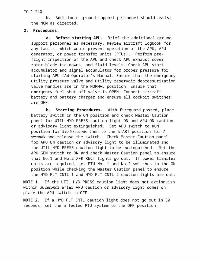
TC 1-240TASK 2079
Perform amphibious operations
CONDITIONS: In a CH-47 helicopter.
STANDARDS: Appropriate common standards plus these additions/modifications:
1. Rated:
a. Ensure water operations briefing is completed to include a review of mission re-lated emergency procedures.
b. Ensure the aircraft is prepared for water operations according to TM 1-1520-240-10 and static line installed. (During ramp down operations, remove the ramp drain plugs)
c. Observe water operation limitations according to TM 1-1520-240-10.
d. Do not exceed ground control limitations.
e. Maintain hover altitude 15 feet ± 5 feet, above the water.
2. Nonrated:
a. Configure the aircraft for water operations per TM 1-1520-240-10.
b. Assist the pilots in a reconnaissance of the intended landing area.
c. Clear the aircraft during the landing and takeoff.
d. Advise the pilots prior to the water reaching fuselage station 400.
e. Perform crew coordination actions.
f. Enter appropriate information on the DA Form 2408-13 and ensure that required inspections and servicing are completed IAW TM 10-1520-240-23-1.
DESCRIPTION:
1. Crew actions.
a. The PC will conduct a crew and passenger briefing and ensure all personnel are familiar with aircraft safety and emergency procedures IAW the unit SOP.
b. The P* should make the approach into the wind if possible.
c. The P will provide the P* with information regarding airspeed and altitude. The P will also monitor the cockpit indications. The P will ensure that the PITOT HEAT switch is turned ON, both search lights switches are OFF, and the control switches are in the RETR position. The P and NCM will announce when his attention is focused inside the aircraft and again when attention is reestablished outside.
d. The NCM will advise the pilots of any unusual water accumulation in the cargo area. During ramp down operations, advise the pilots of the water level prior to reaching fuselage station 400.
2. Procedures.
a. Rated.
(1) Upon arrival at the landing area, perform a VMC approach to arrive at a 15-foot hover with no forward movement. During the approach inspect the landing area for debris and abort the landing if the landing site is not clear of obstructions. When landing, reduce the thrust
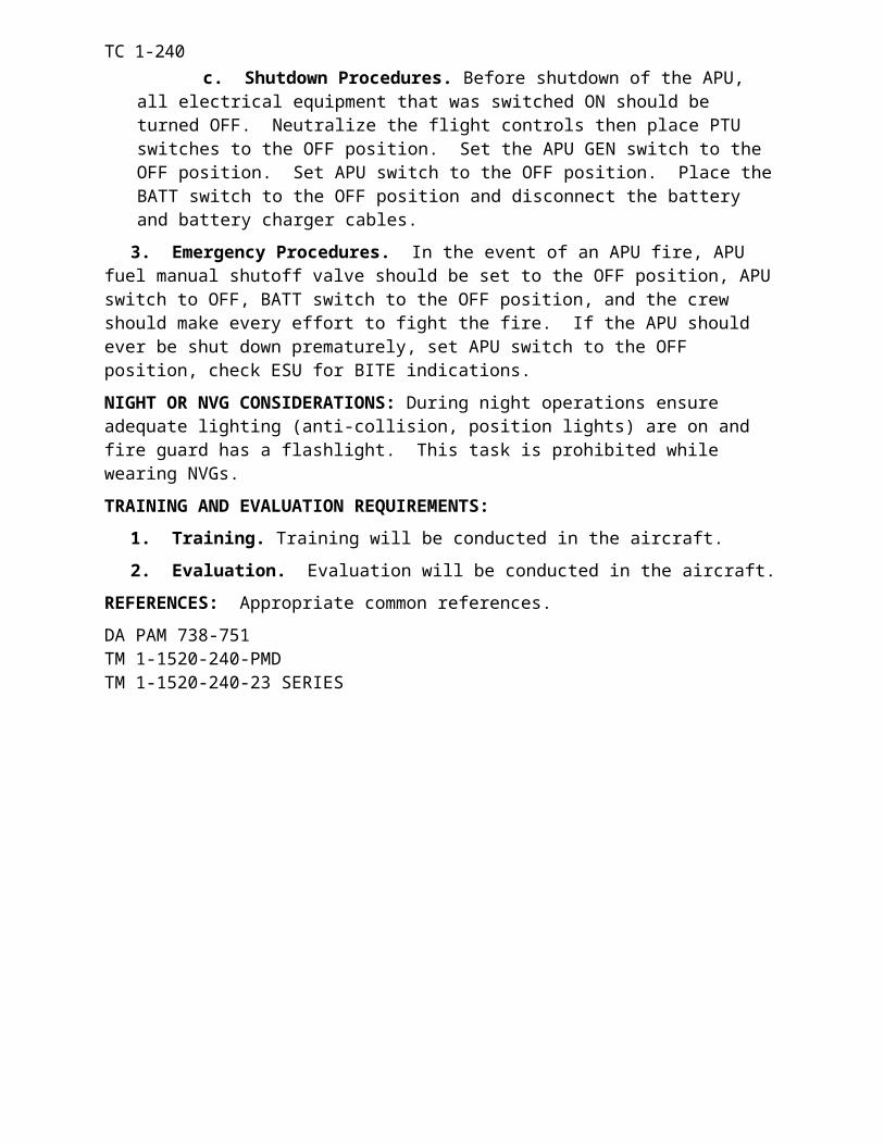
TC 1-240to a power setting that prevents the water form coming forward of fuselage station 400. (As per the water landing AWR)
(2) Maintain the controls at neutral for a forward speed of 4 to 6 knots. During ramp down operations don not apply aft cyclic or reduce engine beep trim to slow the taxi speed. At speeds up to 5 knots, use the pedals and cyclic to make turns. Turning will not be performed during ramp down operations.
(3) Raise the thrust control to make a vertical ascent to approximately 15 feet above the water. Perform hover power check and before takeoff checks. Perform a VMC take off. Place the PITOT HEAT switch to the OFF position.
NOTE 1. CH-47 aft landing gear switches are not actuated in the water. The dash actuators will continue to respond to longitudinal stick inputs. Longitudinal cyclic movements of 0.1 inch, if held, may cause the DASH actuators to hard-over. If longitudinal cyclic movement is required for taxing, set the AFCS SEL switch to OFF.
NOTE 2. Hovering over water with minimum drift is difficult and requires proper scanning techniques and proper crew coordination. If possible, select a stationary object as a visual reference.
NOTE 3. Water Operation (Ramp Down) Considerations:
1. A safety boat is present when performing recovery operations.
2. Brief medical support available.
3. Communication must be maintained during recovery operations.
b. Nonrated.
(1) Before the flight, ensure the center cargo hook is towed and the lower rescue door secure. Install all fuselage drain plugs (during ramp down water operations do not install ramp drain plugs). Inspect the seal on all lower antenna mounts and inspect access panels for security. Install static line for use as a handhold.
(2) During the approach, perform a reconnaissance of the landing area. Assist the pi-lots in determining the suitability of the landing area.
(3) During the descent, advise the pilots, in 25-foot increments, of he height of the aircraft above the water. Advise the pilots if any debris or submerged objects are near the land-ing site. At 10 feet, advise the pilots, in one-foot increments, of the height of the aircraft until the aft wheels contact the water. During descent for ramp down operations, the crewmember po-sitioned at the forward cabin door will report altitudes from 100 feet to 25 feet to 10 feet in 5 foot increments, 10 feet to one foot in one foot increments followed by a report of ramp contact with the water.
(4) While in the water, advise the pilots of any unusual water accumulation in the cargo area. During ramp down operations, advise the pilots of the water level prior to reaching fuselage station 400.
(5) During takeoff, advise the pilots when the wheels are clear of the water (ramp clear during ramp down operations.
(6) At the completion of he mission, enter appropriate information on the DA Form 2408-13. Ensure that all required inspections and service are performed.
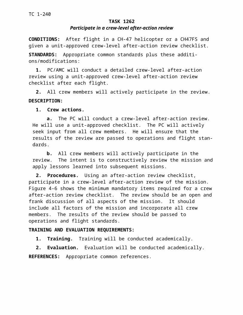
TC 1-240OVERWATER CONSIDERATIONS: Over water flight, at any altitude, is characterized by a lack of visual cues, and therefore, has the potential of causing visual illusions. Be alert to any unannounced changes in the flight profile and be prepared to take immediate corrective actions. The radar altimeter low bug should be set to assist in altitude control. Hazards to terrain flight such as harbor lights, buoys, wires, and birds must be considered during over water flight.
NOTE: There is a high probability the Doppler (AN/ASN-128) MEM indicator lamp will light while flying over glassy smooth water. However, if the lamp remains on for over 10 minutes, over land or rough water, there is a malfunction in the Doppler set.
NIGHT OR NVG CONSIDERATIONS: Spatial disorientation can be overwhelming during over water operations at night. If there are visible lights on the horizon or if the shoreline can be seen, the pilot may opt to approach the cast area so the aircraft is pointed toward these refer-ences, if the wind permits. Proper scanning techniques are necessary. Conditions specified in the aircraft operator’s manual must be met before the aircrew conducts water operations at night.
TRAINING AND EVALUATION REQUIREMENTS:
1. Training. Training will be conducted in the aircraft.
2. Evaluation. Evaluation will be conducted in the aircraft.
REFERENCES: Appropriate common references plus the following:
Airworthiness release for CH-47D Helicopters to Conduct Water Landing.
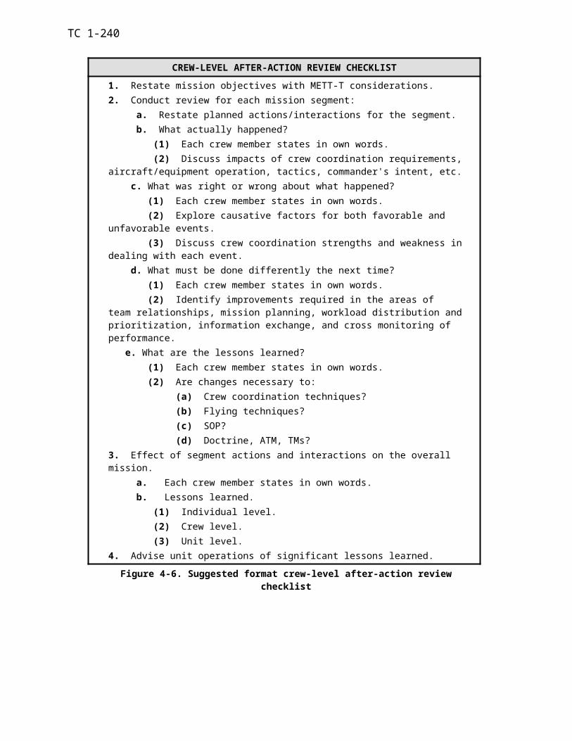
TC 1-240TASK 2086
Operate NVG with the AN/AVS-7 (ANVIS HUD) attached
CONDITIONS: In a CH-47 helicopter or a CH-47FS.
STANDARDS: Appropriate common standards plus describe and demonstrate correct terminol-ogy and usage of the AN/AVS-7 IAW TM 11-5855-300-10.
DESCRIPTION: Perform operational procedures for the AN/AVS-7. These include assembly, preparation for use, operating procedures, and equipment shutdown.
TRAINING AND EVALUATION REQUIREMENTS:
1. Training. Training may be conducted in the aircraft or simulator.
2. Evaluation. Evaluation will be conducted in the aircraft.
REFERENCES: Appropriate common references plus TM 11-5855-300-10.
TC 1-240TASK 2112
Operate armament subsystem
WARNING
Observe all safety precautions for uploading ammunition in accordance with TM 9-1095-206-13. To prevent accidental firing, do not retract bolt and allow it to go forward if belted ammunition is in feed tray, or a live round is in chamber. Move cocking handling forward by hand.
CONDITIONS: In a CH-47 helicopter with the armament subsystem installed.
NOTE: This task only applies to NCMs .
STANDARDS:
1. Install and preflight the armament subsystem per the aircraft and subsystem operator’s manual.
2. Load and safe the weapon.
3. Acquire and identify target.
4. Estimate range to target.
5. Engage target(s) IAW weapon mission briefing, control measures, and Rules of Engage-ment (ROE).
6. Apply firing techniques.
7. Suppress, neutralize, or destroy as applicable.
8. Describe or perform emergency procedures for misfire, hang-fire, cook-off, runaway gun, and double feeding.
9. Clear and safe the weapon.
10. Enter appropriate information if required on DA Forms 2408-12, -13, and DA Form 13-1
DESCRIPTION:
1. Crew actions. The NCM will coordinate with and brief any additional ground support personnel prior to installation and loading of the weapon system. Perform installation and pre-flight inspection of the weapons system. He will brief all concerned personnel on procedures to be followed in case of an emergency. The NCM will direct assistance from any additional ground support personnel to aid in installation and loading of the weapon. He will ensure that the proper amount of ammunition is loaded on board the aircraft IAW the mission briefing.
2. Procedures. Brief additional ground support personnel as necessary. Perform installa-tion and pre-flight inspection of the weapon ensuring that the gun is safetied to the pintle. En-sure that the ejector control bag and ammunition can is installed. During loading of ammunition, observe all safety precautions while loading. After loading the ammunition ensure the safety button is in (S) position. To initiate the firing sequence, push the safety button to the (F) posi-tion, press the trigger fully and hold. Low cycle rate of fire of the machinegun allows firing of single rounds or short bursts. The trigger must be completely released for each shot. Conduct weapons engagement IAW the mission briefing, ROE, and crew briefing. After acquiring and identifying the target, estimate range and ensure that the target is within the weapons field of
TC 1-240range and the kill zone is within the weapons effective range. Use correct firing techniques and ballistic corrections to successfully suppress, neutralize, or destroy as applicable the threat. Con-sideration must be given to the visibility of friendly and enemy positions and trying to preclude any undesirable collateral damage or fratricide incidents. Perform any firing malfunctions emer-gency procedures as required for misfire, hang-fire, cook-off, runaway gun, or double feeding of cartridges. Firing malfunctions and corrective actions must be committed to memory. After tar-get engagement, clear and safe the weapon. Ensure the safety button is in the (S) position. After completion of the mission record any information as required on DA Forms 2408-12, -13, or DA Form 13-1. Refer to Chapter 2 and FM 3-04.140 for details on helicopter gunnery qualification.
MULTI-HELICOPTER DOOR GUNNER EMPLOYMENT: Aircrews and door gunners in the formation must use effective crew coordination procedures to visually acquire, identify, and engage targets. Both aircraft and passengers are vulnerable to attack during air movement opera-tions and throughout all phases of air assault operations. Therefore, it is imperative that door gunners respond by delivering direct and indirect fires on these targets. The unit must develop SOP’s covering the employment of door gunners during formation flights.
NIGHT OR NVG CONSIDERATIONS: During night or NVG operations range estimations will be more difficult which will require proper scanning technique utilization. Correct firing techniques and ballistic corrections will be more critical for target suppression or destruction. During firing, while wearing NVGs, target loss may accrue monetarily due to muzzle blast and the brightness of the tracers.
TRAINING AND EVALUATION REQUIREMENTS:
1. Training. Training will be conducted in the aircraft and academically.
2. Evaluation. Evaluation will be conducted in the aircraft.
REFERENCES: Appropriate common references plus the following:
FM 3-04.140
TC 1-240TASK 2125
Perform Mountain/Pinnacle and ridgeline Operations.
CONDITIONS: In a CH47 helicopter or a CH47 Flight Simulator with the before landing check completed and hover OGE power available.
STANDARDS: Appropriate common standards plus these additions/modifications:
1. RCM actions:
a. Correctly determine power requirements/weight limitations prior to conducting this task.
b. Cross major ridgelines at a 45º angle.
c. Correctly determine wind direction for pinnacle landing.
d. Maintain a constant approach angle
e. Align aircraft with landing direction below 100 feet or as appropriate for transition from terrain flight.
f. Maximum rate of descent during the last 100 feet of a pinnacle approach will not ex-ceed 300 feet per minute.
g. Properly clear the aircraft for the landing area.
2. NCM actions:
a. Assist in determining the suitability of the landing area for the operation being per-formed.
b. Properly clear the aircraft for the landing area.
DESCRIPTION:
1. Crew actions.
a. Determine power requirements for the conditions at takeoff, cruise and arrival using current/forecast pressure altitude and temperature. Prior to takeoff, analyze winds, obstacles, and density altitude. Perform a hover power check, if required. The *P will select a takeoff angle, depending on the wind (demarcation line), density altitude, gross weight, and obstacles. After clearing obstacles, accelerate the aircraft to the desired airspeed.
b. When flying in a valley, the aircraft should be flown in the smoother up-flowing air on the lifting side of the valley (windward side). Under light winds, the aircraft should be flown closer to the side of the valley. This allows maximum distance to turn 180º should it become nec-essary for weather or enemy situation. Additionally, less populated areas are present on the side of the valleys as opposed to the center of the valley. Caution should be used when flying on the leeward side due to potentially significant downdrafts. At higher gross weights and pressure alti-tudes, the maximum allowable airspeed will decrease. It may be necessary to decrease airspeed to remain within aircraft limitations and prevent blade stall.
c. Select an approach angle, depending on winds (demarcation line), density altitude, gross weight, and obstacles. An approach angle of 30º or less will minimize the possibility of set-tling-with-power. During the approach, continue to determine the suitability of the intended land-ing point. The rate of closure may be difficult to determine until the aircraft is close to the land-ing area. Reduce airspeed to slightly above effective translational lift until the rate of closure can be determined. Before reaching the near edge of the landing area, the descent should be stopped
TC 1-240and the rate of closure slowed. At this point, reconfirm performance planning and determine if sufficient power will be available. Based on the performance data, decide whether to continue the approach or make a go-around. If a go-around is required, it should be performed before de-celerating below ETL. If the approach is continued, terminate in the landing area to a hover or to the surface. After touching down, check aircraft stability as the thrust-lever is lowered.
NOTE: A mountain environment is defined IAW FAR part 91 for CONUS. Areas not depicted in FAR part 91 or host country publications will be identified as mountainous when in an area of steeply sloping terrain, with more than 500 feet elevation relief and terrain elevation more than 5000 feet above mean sea level (MSL).
NOTE: To successfully operate into small areas, it may be necessary to place the nose of the aircraft over the edge of the landing area. This may cause a loss of important visual references when on final approach. In some locations, it may not be possible to lower the forward or aft landing gear on the ground while on/off loading. The description for “Perform Slope Landing” in task 1062 may be used for this type of landing. All crewmembers must assist in providing information on aircraft position in the landing area.
TRAINING AND EVALUATION REQUIREMENTS:
a. Training.
(1) Training may be conducted in the aircraft or simulator. Academic and flight training may be conducted at HAATS, or utilizing the HAATS Mountain Training POI if available, or the recommended program of instruction in Chapter 4 of FM 1-202.
(2) The optimal flight training area is an actual mountain environment. If unfore-seen circumstances prevent the accomplishment of this training in the air-craft, then a compatible visual flight simulator may be used for training and evaluation. If a simulator is used for training, the datum plane will be set no lower than 5000 feet MSL for the training area selected. The temperature, wind, and aircraft gross weight should be varied to achieve the maximum training effect.
b. Evaluation. An evaluation may be required at the discretion of the commander in the aircraft or simulator.
NIGHT OR NVG CONSIDERATIONS: More detailed flight planning is required when the flight is conducted at night. Interior cockpit lighting should be considered when selecting colors for preparing navigational aids such as maps and kneeboard notes.
REFERENCES: Appropriate common references.
TC 1-240
CHAPTER 5
MAINTENANCE TEST PILOT TASKS
This chapter describes the tasks that are essential for maintaining maintenance crewmember skills. It defines the task title, number, conditions, and standards by which performance is measured. A description of crew actions, along with training and evaluation requirements is also provided. Tasks described in this chapter are to be performed by qualified CH-47D Maintenance Test Pilots in accordance with AR 95-1. This chapter contains tasks and procedures to be used by contractor maintenance test pilots in accordance with AR 95-20 (DLAM 8210.1 v1 para 3.4 or DLAI 8210.1 encl 2 para 1.k publications). If discrepancies are found between this chapter and TM 1-1520-240-MTF, the MTF takes precedence.
5-1 TASK CONTENTS
a. Task Number. Each ATM task is identified by a ten-digit Systems Approach to Training number that corresponds to the maintenance test pilot tasks listed in Chapter 2 (Ta-ble 2-12). For convenience, only the last four digits are referenced in this training circular.
b. Task Title. This identifies a clearly defined and measurable activity. Task titles may be the same in many ATMs, but task content will vary with the airframe.
c. Conditions. The conditions specify the common, wartime, or training/evaluation conditions under which the MTP tasks will be performed.
d. Standards. The standards describe the minimum degree of proficiency or stan-dard of performance to which the task must be accomplished. Standards are based on ideal conditions to which the task must be accomplished. The following common standards apply to all MTP tasks.
(1) Perform procedures and checks as per applicable MTF manual, as required.
(2) Brief the RCM and/or NCM on the procedures, applicable Warnings, and Cau-tions, for the task to be performed. If performing an autorotation RPM check, TEAC, and/or PAC a detailed brief will be conducted to include limitations, thrust positions of ground detent, full down, relaxed position, power recovery (autorotation), and emergency procedures for single or dual engine failure during the various stages of each maneuver.
(3) Perform crew coordination actions per the task description and Chapter 6 of TC 1-240.
(4) Assess and address any malfunctions or discrepancies as they occur and apply ap-propriate corrective actions or troubleshooting procedures.
(5) Use the oral callout and confirmation method and announce the initiation and completion of each check.
(6) Direct assistance from other crew members as required.
(7) When a system or engine is not subject to a specific MTF manual check, ensure the system is checked in accordance with the operator’s manual. An example is a LTF for a NO. 1 engine replacement, the NO. 2 must have the operator’s manual checks performed i.e. emer-gency engine beep trim system, HIT, FADEC reversionary check, PAT , etc.
(8) Anytime an ECL is moved to the GND position, the MP will verify the engine is stabilized at ground idle.
5-1
TC 1-240
e. Description. The description explains how the elements of the task should be done to meet the standards. When specific crew actions are required, the task will be broken down into crew actions and procedures as follows.
(1) Crew actions. These define the portions of a task to be performed by each crewmember to ensure safe, efficient, and effective task execution. When required, MP responsi-bilities are specified. All tasks in this chapter are to be performed only by qualified MPs/ MEs, or student maintenance test pilots undergoing qualification training as outlined in AR 95-1. The MP is the PC in all situations, except when undergoing training or evaluation by an ME. For all tasks, MP actions and responsibilities are applicable to MEs. When two MEs are conducting training/evaluation together, or two MPs are jointly performing test flight tasks, the mission brief will designate the aviator assuming PC responsibilities.
(2) Procedures. This section includes additional information to augment the MTF manual.
(3) Crew Stations. For GTFs, the MP will be in the left seat. For LTFs, this section will identify when the MP must be in the left seat to ensure safe, efficient, and effective comple-tion of task execution. These tasks are also listed below.
Starting Engine Checks: Control interference, neutral pedal measurement, cyclic position indicator check, 714 engine start abort, engine start, 714 over speed, 714 reversionary start, 712 minimum beep, 712 bleed band.
Engine run-up checks: Generator under-frequency and emergency engine trim system.
Before Hover check: FADEC system.
Hover: Mechanical rig, control position, and torque differential.
In-flight checks: 60 and 140 KIAS speed sweep if lateral and/or pedal measurements are required, autorotation, TEAC, and PAC.
f. Training and Evaluation Requirements.
(1) Training and evaluation requirements, other than RL progression and APART, tasks can be performed and/ or evaluated in the aircraft, simulator, or academic environment. The evaluation criteria are addressed in the standard section of this chapter and any additional standards in the specific task. If one or more checks are performed unsatisfactorily, the task will be graded unsatisfactory. However, when the task is reevaluated, only those unsatisfactory checks must be reevaluated.
The following checks, as a minimum will be evaluated for MP/ME APART purposes:
Preflight
Control interference
Control Interlock
Control centering
The following engine checks (one engine only)
714 engine abort start
Engine start (714 Primary and Reversionary)
714 Over-speed
5-2
TC 1-240
714 Reversionary beep
712 Minimum beep
712 Bleed band
712 Emergency engine trim check
714 FADEC system (including reversionary)
Generator under-frequency
Ground instability
AFCS function, hover and in-flight (Both, NO. 1, or NO. 2)
Torque differential
Droop eliminator
Autorotation RPM
TEAC (712 only)
PAC including calculating a PAT trigger value (714 only)
(2) The evaluator may select additional checks for evaluation. For MP APART the MP will be in the left seat. For ME APART the examinee will be in the right seat. The ME evaluator can be in the left seat or other crew station, if authorized on his DA Form 7120, and there is a qualified MP in the left seat. The ME will be evaluated on his ability to evaluate, assist, and recover from the minimum tasks and any additional task(s) as selected by the evaluator.
(3) If the MP/ME is required to perform MTFs in CH-47s equipped with 712 engines and CH-47s equipped with 714 engines the MP/ME APART must be completed in both. Only the engine peculiar tasks need to be accomplished in the second aircraft as follows:
712 714
Engine Start* DECU Pre-start BIT*
Minimum Beep Abort Start
Bleed Band Check Engine Start*
Emergency Engine Trim Check P3 Bellows
Torque Differential Overspeed
Autorotation Reversionary Engine Start
TEAC DECU Start BIT*
FADEC System Check
Torque Differential
Autorotation
PAC
PAT*
*These tasks are only required if they were not evaluated on the APART Standardization Evaluation
5-3
TC 1-240
(1) References. The references are sources of information relating to that particular task. In addition to the common references listed in Chapter 4, the following references apply to all MTP tasks:
Aircraft logbook and historical records.
TM 1-1500-328-23.
DA PAM 738-751.
TM 1-1520-240-10 .
TM 1-1520-240-CL.
TM 1-1520-240-MTF.
TM 55-1520-240-23 series manuals .
TM 11-1520-240-23 series manuals.
TM 55-2840-254-23.
TM 1-2840-265-23
TM 1-6625-724-13&P.
Applicable airworthiness directives or messages from AMCOM.
5-2 TASKS
(1) Standards versus Descriptions. The standards describe the minimum degree of proficiency or standard of performance to which the task must be accomplished. Attention to the use of the words, will, should, shall, must, or may throughout the text of a task standards is crucial.The description explains one or more recommended techniques for accomplishing the task to meet the standards
(2) Critical Task. The following numbered tasks are CH-47 maintenance pilot critical tasks.
5-4
TC 1-240
TASK 4000Perform prior to maintenance test flight checks.
CONDITIONS: In a CH-47D helicopter.
STANDARDS: Appropriate common standards plus these additions/modifications:
1. Perform the preflight inspection according to applicable MTF manual.
2. Determine the suitability of the aircraft for flight and the mission to be performed.
3. Determine the maneuvers, checks, and tasks required during the test flight.
4. Ensure all ‘FOLLOW-ON’ maintenance/checks/inspections are entered in logbook and completed.
DESCRIPTION:
1. Crew actions. The MP will ensure that a thorough preflight inspection is conducted. The MP will ensure that the aircraft logbook forms and records are reviewed and appropriate entries made as per DA PAM 738-751. The RCM should complete the assigned elements and report the results to the MP.
2. Procedures. Perform in accordance with the MTF for GTFs and the MTF or the opera-tor’s manual for LTFs. The MP will personally preflight the areas that were involved in the maintenance activity(s) that require the MTF utilizing the MTF manual and may direct the RCM, if available, to complete such other elements of the aircraft preflight inspection as are appropri-ate. The MP will verify that all the checks have been completed.
REFERENCES: Appropriate common references.
5-5
TC 1-240
TASK 4001Perform MTF before starting engine checks
CONDITIONS: In a CH-47D helicopter.
STANDARDS: Appropriate common standards.
DESCRIPTION:
1. Crew actions.
a. The MP will perform the checks in sequence.
b. The RCM and NCM should assist the MP as directed.
2. Procedures. Perform as per the MTF manual.
REFERENCES: Appropriate common references.
5-6
TC 1-240
TASK 4002Perform MTF starting engine checks
CONDITIONS: In a CH-47D helicopter.
STANDARDS: Appropriate common standards plus these additions/modifications:
1. During RRPM adjustments with the emergency or normal engine beep trim ensure the RRPM remains within normal operating RRPM in accordance with the operator’s manual.
2. During the Cyclic Stick Position Indicator check, determine if measurement is to the bot-tom of the “ball” or the bottom of the red marking on the stick position indicator.
DESCRIPTION:
1. Crew actions.
The MP must personally perform the following: control interference, obtain neutral pedal measurement, control break-out forces check, flight control and travel checks in BOTH and NO. 1 or NO. 2 hydraulic systems, the minimum beep check, and the 712 engine bleed band check. Appropriate operator’s manual checks must be completed for systems and / or engines where MTF checks are not completed.
2. Procedures. Perform as per the MTF manual and as follows:
a. Anti-collision light check: Ensure each switch controls its respective light.
b. Cyclic trim actuator check: Ensure each actuator switch controls its respective actuator during the retract portion of the check.
c. During the control interference check: Move either pedal full forward until it contacts its stop and ensure the opposite pedal does not contact the cockpit floor and does not make contact in accordance with the NOTE in the MTF manual. Move the cyclic full forward and then toward the pedal that is fully aft. Ensure the cyclic does not contact the pedal adjustment lever or contacts in accordance with the NOTE in the MTF manual. The pedal should kick-out as the cyclic comes in close proximity with the pedal. Neutralize the cyclic and move the other pedal full forward checking for non-interference as stated above.
d. Obtain neutral pedal measurement: Center the pedals and release the centering device release switch. The pedals do not need to be exactly centered. With a tape measure, measure from the cyclic boot plate to each pedal noting each measurement allowing the tape to rest on the cockpit floor. Mathematically compute the neutral position. Placing the pedals at precisely neutral is not required at this point as the flight control travel check is to be ac-complished later. The neutral pedal measurement will allow the measurement of only one pedal for the hover and in-flight yaw control position checks.
e. Cyclic stick position indicator check: With the cyclic set to the placard mea-surement note the exact position of the stick position indicator. This will be used as a refer-ence for future longitudinal measurements.
f. Flight control and travel check: Ensure full range of travel and positive contact with the mechanical stops in the pitch, roll, yaw, and thrust axis.
g. Control centering check: Depress the cyclic control centering release switch and move the cyclic to the mechanical stop in any axis. Release the switch and ensure the cyclic stays within ½ inch of where the switch was released. Without depressing the switch move the cyclic to the other stop in the same axis and allow the cyclic to return to the original stop without
5-7
TC 1-240
releasing the cyclic and possibly damaging the flight controls. The cyclic shall return to the approximate original position where the centering device release switch was released. Check the remaining three cyclic axis position stops as stated above. Check the yaw in the same manner first with either pedal full forward and then releasing the centering device release. That pedal should hold within ½ inch. Without pressing the centering device release move the other pedal to the full forward position and then allow it to return to its original position without releasing it and possibly damaging the flight controls. .
h. During engine starting: The MP will physically man the ECL until the engine has stabilized at ground idle.
i. 714 Over-speed check:- The MP may perform this check completely or have the RCM assist him with the overs-speed switch. Ensure the RCM is fully briefed on his role during the check. The MP will then have to man the thrust control. Hold the over speed switch and wait for the fuel flow to drop to approximately 300PPH then begin to increase before placing the ECL to the STOP position. This will ensure that the over speed valve closes and opens properly.
j. 712 Engine beep trim check: The MP will physically man the ECL until completion of the check. The pilots NO.1 and NO.1&NO.2 engine beep trim switches will be checked for proper response by slightly increasing then decreasing each switch.
k. 712 Engine minimum beep check: If adjustments are made to the minimum beep resistor the MP will physically man the ECL until completion of the check.
l. 712 Bleed band check: There are three ways of manipulating the engines to accomplish this check using either the normal or emergency beep trim.
(1) Place the emergency beep trim auto/manual switch for the engine not being checked to the MANUAL position and use the NO. 1 & NO. 2 normal engine beep trim switch to close the bleed band of the engine being checked.
(2) Place the NO. 1 EMERG ENG TRIM AUTO/MANUAL switch to the MAN-UAL position and slowly increase N1 speed by engaging the NO. 1 engine EMERG ENG TRIM switch to INC for short intervals until bleed band closure occurs. After completion return engine to noted N1 speed and place the NO.1 EMERG ENG TRIM AUTO/MANUAL switch to AUTO. Repeat the procedure for the NO. 2 engine.
(3) Select the AUTO/MANUAL switch of the engine not being checked to the MANUAL position, and slowly decrease the N1 speed by engaging the EMERG ENG TRIM switch to DECR for short intervals until bleed band closure occurs on the engine being checked (opposite from the engine being beeped). After completion return engine to noted N1 speed and place the EMERG ENG TRIM AUTO/MANUAL switch to AUTO. Repeat the procedure for the other engine.
1. CREW STATIONS. For LTFs the MP must be in the left seat if any of the following MTF checks need to be accomplished: flight control and hydraulics checks, 714 abort start check, engine start check, neutral pedal position check, cyclic position indicator check, 714 over-speed check, 714 reversionary check, 712 minimum beep check, and/ or 712 bleed band check.
REFERENCES: Appropriate common references.
5-8
TC 1-240
TASK 4003Perform MTF engine run-up checks
CONDITIONS: In a CH-47D helicopter.
STANDARDS: Appropriate common standards plus these additions/modifications:
1. During the generator under-frequency check maintain RRPM in accordance with the MTF manual.
2. During the emergency engine trim check monitor the engine for possible failure and ex-cessive PTIT.
DESCRIPTION:
1. Crew actions. The MP must personally perform the generator under-frequency and emergency engine trim checks. Appropriate operator’s manual checks must be completed for systems and / or engines where MTF checks are not completed.
2. Procedures. Perform as per the MTF manual.
3. Crew stations. For LTFs, the MP must be in the left seat for the generator under-fre-quency and emergency engine trim checks.
REFERENCES: Appropriate common references.
5-9
TC 1-240
TASK 4004Perform MTF taxi checks
CONDITIONS: In a CH-47D helicopter.
STANDARDS: Appropriate common standards.
DESCRIPTION:
1. Crew actions. Appropriate operator’s manual checks must be completed for systems and / or engines where MTF checks are not completed.
2. Procedures. Perform as per the MTF manual.
REFERENCES: Appropriate common references.
5-10
TC 1-240
TASK 4005
Perform MTF before hover checks
CONDITIONS: In a CH-47D helicopter.
STANDARDS: Appropriate common standards plus the addition/modification:
1. During the FADEC system check do not allow the RRPM to exceed 106%.
DESCRIPTION:
1. Crew actions. The MP must personally perform the FADEC systems and ground instabil-ity checks. Appropriate operator’s manual checks must be completed for systems and / or en-gines where MTF checks are not completed.
2. Procedures. Perform as per the MTF manual and as follows:
a. Ground instability check:
(1) If the brakes don’t hold, set the aircraft down and reset the brakes.
(2) The MP will also be on the controls the first time the aircraft is brought to a com-plete hover following the completion of a required ground instability check.
3. Crew stations. For LTFs, the MP must be in the left seat for the FADEC systems checks.
REFERENCES: Appropriate common references.
5-11
TC 1-240
TASK 4006
Perform MTF hover checks
CONDITIONS: In a CH-47D helicopter.
STANDARDS: Appropriate common standards.
DESCRIPTION:
1. Crew actions. The MP must personally perform the AFCS functional check. The MP will perform the torque differential check while manning the beep trim switches and monitoring the thrust control. Appropriate operator’s manual checks must be completed for systems and / or en-gines where MTF checks are not completed.
2. Procedures. Perform as per the MTF manual.
a. AFCS functional check- During the pitch check the 3 degree input should be momentary to induce an oscillation. Relax pressure on the cyclic to allow it to return to de-tent. Ensure all steps are completed. For the operational check of the pilot’s AFCS trim switch the MP will have the pilot operate the AFCS trim switch i.e. the MP directs the pilot to momentarily place the AFCS trim switch to forward position, while checking that the air-craft responds accordingly.
b. Droop eliminator check- The thrust may have to be increased slightly to stop bleed band cycling. If the torques are stabilized but slightly mismatched, 1 to 4%, and the RRPM is stable at 100% the maneuver may be performed. The mismatch in torque must be applied to the readings when stabilized at a hover to obtain the end results.
3. Crew stations. For LTFs the MP must be in the left seat for the mechanical rig, the con-trol position, and the torque differential checks.
REFERENCES: Appropriate common references.
5-12
TC 1-240
TASK 4007Perform MTF in-flight checks
CONDITIONS: In a CH-47D helicopter.
STANDARDS: Appropriate common standards plus these additions/modifications:
1. Do not allow the airspeed to exceed 100 KIAS during the single AFCS evaluation.
DESCRIPTION:
1. Crew actions. The MP must personally perform the AFCS evaluation.
2. Procedures. Perform as per the MTF manual.
a. AFCS functional check- Ensure all steps are completed.
b. Nav/comm, miscellaneous instrument readings, and instrument readings- Need to be completed for GTFs but only the applicable portion(s) needs to be completed for LTFs.
3. Crew stations. For LTFs the MP must be in the left seat for the 60 and 140 KIAS speed sweep checks if the lateral stick position and/or directional pedal separation measurement is re-quired. For the remainder of the speed sweeps and the longitudinal only for the 60 and 140 the MP may be in the right seat as long as he has verified the stick position indicator during TASK 4002.
REFERENCES: Appropriate common references.
.
5-13
TC 1-240
TASK 4008Perform autorotation RPM check
CONDITIONS: In a CH-47D helicopter with EMERG ENG Trim check completed.
STANDARDS: Appropriate common standards plus these additions/modifications:
1. Re-brief the RCM just prior to the maneuver. As a minimum the thrust positions of ground detent, thrust to the floor, relaxed position, and power recovery.
2. Select a suitable autorotation area that will permit a safe descent and emergency touch-down straight in landing into the prevailing wind.
3. Accomplish the power recovery prior to 1000 feet AGL.
4. Readings taken in a stabilized autorotational glide at 75 +/- 5 KIAS, in trim, with thrust control full down.
5. MP will man the thrust control and guard the (712) EMERG ENG TRIM switches throughout the maneuver.
6. The NCMs will be seated with seat belts fastened throughout this maneuver.
DESCRIPTION:
1. Crew actions. Prior to the maneuver the MP will re-brief the RCM on the maneuver es-pecially the thrust positions of ground detent, thrust to the floor, relax pressure, and power recov-ery. The MP will man the thrust throughout the maneuver until power recovery is confirmed, but the RCM has control of all the flight controls. The MP may call out the RRPM and PA at the point at which the readings are taken to the NCM who can write them down for recording after the maneuver is completed.
2. Procedures. Perform as per the MTF manual. Additionally the MP will man and monitor the thrust to ensure the thrust is in the appropriate positions. The MP should not be hesitant to place the thrust into the correct position. When at the ground detent analyze the RRPM, if it is climbing rapidly the MP may decide to terminate the maneuver. The MP must decide if environ-mental factors i.e. wind, turbulence, etc or aircraft airspeed change may have affected the RRPM and decide whether or not to attempt the maneuver again. If continuing the maneuver the MP will then direct the placing of the thrust to the floor. The MP will then incrementally decrease both EMERG ENG TRIM switches ensuring the N1s of each engine are below 70% and remain above 60%. Once stabilized and readings taken, the thrust movement during power recovery will depend on the RRPM. If RRPM is 102% or below the thrust can remain full down until the 712 EMERG ENG TRIM covers are placed in the down position or the 714 FADEC NR rotary switch is placed to the 100% position. If the RRPM is greater than 102% the thrust may be al-lowed to come up under the force of the ground detent capsule, “relaxed position” while simulta-neously recovering the engines. There is no need to wait until the RRPM starts to decrease be-fore the engines are recovered. At recovery, place EMERG ENG TRIM covers down one at a time with only a momentary pause between them. No need to place one down and wait until the engine responds before placing the other cover down. If an emergency situation occurs the MP will announce the emergency and take appropriate corrective action.
3. Crew stations. The MP must be in the left seat for this maneuver
REFERENCES: Appropriate common references
5-14
TC 1-240
TASK 4009Perform turbine engine analysis check (TEAC) 712
CONDITIONS: In a CH-47D helicopter with topping stop(s) installed and before TEAC main-tenance checks complete.
STANDARDS: Appropriate common standards plus these additions/modifications:
1. Select a suitable flight track that will permit a safe descent and emergency landing.
2. Re-brief the RCM just prior to the maneuver, especially the possible emergency proce-dures.
3. Initiate the TEAC at a minimum altitude of 1,500 AGL.
4. Maintain at or below any one of the following limits: PTIT 890 degrees, N1 105%, Torque of 123%, or 140 KIAS. If the emergency power light comes on do not allow it to remain on longer than 5 seconds or the emergency power indicator flag will trip and the timer will start counting.
5. The NCMs will be seated with seat belts fastened forward of the cabin center rescue hatch throughout this maneuver.
DESCRIPTION:
1. Crew actions. Prior to the maneuver the MP will re-brief the RCM on the maneuver espe-cially the possible emergency procedures. The MP will man the ECL and the thrust throughout the maneuver, but the RCM has control of all the flight controls. The MP may call out the N1, PTIT, Torque and PA at the point at which the readings are taken to the NCM who can write them down for recording after the maneuver is completed.
2. Procedures. Perform as per the MTF manual. Additionally the MP will pull the ECL of the engine to be TEACed from the flight detent, which will cause the master caution and ENG N1 CONT segment light to illuminate. The MP will reset the master caution. He will then coor-dinate the retarding the ECL with the adjustment of RRPM with the normal engine beep trim NO.1 & NO.2 switch to maintain RRPM, while monitoring N1, PTIT, and torque. When the ECL is in the ground position check the engine not being TEACed is stable at ground idle. Ad-vise the RCM to increase airspeed as required to maintain the altitude. While monitoring N1, PTIT, the emergency power light, and torque the MP will increase thrust and beep until the beep no longer responds. Do not allow the emergency power light to remain on longer than 5 second or the flag will trip. During the recovery coordinate the advancing of the ECL of the non-TEACed engine with the normal engine beep trim NO.1 & NO.2 switch until the ECL is in the flight position and dual engine matched torque is achieved. If an emergency situation occurs the MP will announce the emergency and take appropriate corrective action.
3. Crew stations. The MP must be in the left seat for this maneuver
REFERENCES: Appropriate common references
5-15
TC 1-240
TASK 4010Perform maximum continuous power check/ perform maximum power check (MCPC/ MPC) 714.
CONDITIONS: In a CH-47D helicopter or CH-47FS.
STANDARDS: Appropriate common standards plus these additions/modifications:
1. Select a suitable flight track that will permit a safe descent and emergency landing.
2. Initiate the PAC at a minimum of 1,500AGL.
3. Maintain at or below any one of the following limits: 899 degrees PTIT, N1 110%, Torque of 123%, or 140 KIAS.
4. The NCMs will be seated with seat belts fastened forward of the cabin center rescue hatch throughout this maneuver.
DESCRIPTION:
1. Crew actions. Prior to the maneuver the MP will re-brief the RCM on the maneuver espe-cially the possible emergency procedures. The MP will man the ECL and the thrust throughout the maneuver, but the RCM has control of all the flight controls. The MP may call out the N1, PTIT, Torque, fuel flow, and PA at the point at which the readings are taken to the NCM who can write them down for recording after the maneuver is completed.
2. Procedures. Perform as per the MTF manual. Additionally, the MP will retard the ECL monitoring N1, PTIT, and torque until the minimum torque is achieved. If the ECL reaches the ground position, check the engine not being PACed is stable at ground idle. Advise the RCM to increase airspeed as required to maintain the altitude. While monitoring N1, PTIT, and torque the MP will increase thrust until the minimum torque is achieved before the calculated maximum N1 for MCPC or MPC and/or maximum PTIT for MCPC 806 or MPC 899 is reached. During the recovery the MP will advance the ECL of the non-PACed engine until the ECL is in the flight position and dual engine flight is achieved. If an emergency situation occurs the MP will announce the emergency and take appropriate corrective action.
3. Crew stations. The MP must be in the left seat for this maneuver
REFERENCES: Appropriate common references
5-16
TC 1-240
TASK 4011Perform communication and navigation equipment checks
CONDITIONS: In a CH-47D helicopter.
STANDARDS: Appropriate common standards.
DESCRIPTION:
1. Crew actions. The MP may perform these checks or direct assistance from the RCM to perform them as appropriate. The P* will remain focused outside during the procedures, maneu-ver as appropriate for the procedure, and maintain airspace surveillance. The MP should direct the NCM to assist with maintaining airspace surveillance.
2. Procedures. Perform as per the MTF manual (Section IV).
REFERENCES: Appropriate common references.
5-17
TC 1-240
TASK 4012Perform after landing through engine shutdown checks
CONDITIONS: In a CH-47D helicopter.
STANDARDS: Appropriate common standards.
DESCRIPTION:
1. Crew actions.
a. The MP will perform the checks in sequence.
b. The RCM and NCM should assist the MP as directed.
2. Procedures. Perform as per the MTF manual.
REFERENCES: Appropriate common references.
5-18
TC 1-240
TASK 4013Perform special equipment or detailed procedures checks
CONDITIONS: In a CH-47D helicopter.
STANDARDS: Appropriate common standards.
DESCRIPTION:
1. Crew actions.
a. The MP will perform the checks in sequence.
b. The RCM and NCM should assist the MP as directed.
2. Procedures. Perform as per the MTF manual or other appropriate reference.
REFERENCES: Appropriate common references. Any additional authorized references includ-ing the AWR.
5-19
TC 1-240
Intentionally left blank.
5-20
TC 1-240CHAPTER 6
CREW COORDINATION
This chapter describes the background of crew coordination development. It also describes the crew coordination elements, basic qualities, and objectives, as found in the Army Aircrew Coordination Enhancement Training Program.
NOTE: Digitization of the crew compartments has expanded and redefined the lines of responsibility for each crew member. The ability for either crew member to perform most aircraft/system functions from his crew station breaks down the standard delineation of duties and has added capabilities in training and in combat. This could mean that during an unforeseen event, one crew member may attempt to resolve the situation on his own rather than seeking assistance from the other crew member. It is essential for the PC to brief specific duties prior to stepping into the aircraft. Effective sharing of tasks relies on good crew coordination and information management.
6-1. CREW COORDINATION BACKGROUND
An analysis of US Army aviation accidents revealed that a significant percentage of these accidents resulted from one or more crew coordination errors committed before or during the mission flight. Often an accident was the result of a sequence of undetected crew errors that combined to produce a catastrophic result. Additional research showed that even when accidents are avoided, these same errors could result in degraded mission performance. A systematic analysis of these error patterns identified specific areas where crew-level training could reduce the occurrence of such errors and break the error chains leading to accidents and poor mission performance.
6-2. CREW COORDINATION ELEMENTS
Broadly defined, aircrew coordination is the interaction between crew members necessary for the safe, efficient, and effective performance of tasks. The essential elements of crew coordination are described below.
a. Communicate positively. Good cockpit teamwork requires positive communication among crew members. Communication is positive when the sender directs, announces, requests, or offers information; the receiver acknowledges the information; the sender confirms the information, based on the receiver's acknowledgment or action.
b. Direct assistance. A crew member will direct assistance when he cannot maintain aircraft control, position, or clearance. He will also direct assistance when he cannot properly operate or troubleshoot aircraft systems without help from the other crew members.
c. Announce actions. To ensure effective and well-coordinated actions in the aircraft, all crew members must be aware of the expected movements and unexpected individual actions. Each crew member will announce any actions that affect the actions of the other crew members.
d. Offer assistance. A crew member will provide assistance or information that has been requested. He also will offer assistance when he sees that another crew member needs help.
e. Acknowledge actions. Communications in the aircraft must include supportive feedback to ensure that crew members correctly understand announcements or directives.
6-1
TC 1-240f. Be explicit. Crew members should use clear terms and phrases and positively
acknowledge critical information. They must avoid using terms that have multiple meanings, such as "Right," "Back
up," or "I have it." Crew members must also avoid using indefinite modifiers such as, "Do you see that tree?" or "You are coming in a little fast."
g. Provide aircraft control and obstacle advisories. Although the P* is responsible for aircraft control, the other crew members may need to provide aircraft control information regarding airspeed, altitude, or obstacle avoidance.
h. Coordinate action sequence and timing. Proper sequencing and timing ensure that the actions of one crew member mesh with the actions of the other crew members.
6-3. CREW COORDINATION BASIC QUALITIES
The crew coordination elements are further broken down into a set of 13 basic qualities. Each basic quality is defined in terms of observable behaviors. The paragraphs below summarize these basic qualities.
a. Flight team leadership and crew climate are established and maintained. This quality addresses the relationships among the crew and the overall climate of the flight deck. Aircrews are teams with a designated leader and clear lines of authority and responsibility. The PC sets the tone for the crew and maintains the working environment. Effective leaders use their authority but do not operate without the participation of other crew members. When crew members disagree on a course of action, they must be effective in resolving the disagreement. Specific goals include the following:
(1) The PC actively establishes an open climate where crew members freely talk and ask questions.
(2) Crew members value each other for their expertise and judgment. They do not allow differences in rank and experience to influence their willingness to speak up.
(3) Alternative viewpoints are a normal and occasional part of crew interaction. Crew members handle disagreements in a professional manner, avoiding personal attacks or defensive posturing.
(4) The PC actively monitors the attitudes of crew members and offers feedback when necessary. Each crew member displays the proper concern for balancing safety with mission accomplishment.
b. Pre-mission planning and rehearsal are accomplished. Pre-mission planning includes all preparatory tasks associated with planning the mission. These tasks include planning for VFR, IFR, and terrain flight. They also include assigning crew member responsibilities and conducting all required briefings and brief-backs. Pre-mission rehearsal involves the crew's collectively visualizing and discussing expected and potential unexpected events for the entire mission. Through this process, all crew members think through contingencies and actions for difficult segments or unusual events associated with the mission and develop strategies to cop with contingencies. Specific goals include the following:
(1) The PC ensures that all actions, duties, and mission responsibilities are partitioned and clearly assigned to specific crew members. Each crew member actively participates in the mission planning process to ensure a common understanding of mission intent and operational sequence. The PC prioritizes planning activities so that critical items are addressed within the available planning time.
6-2
TC 1-240(2) The crew identifies alternate courses of action in anticipation of potential
changes in METT-T and is fully prepared to implement contingency plans as necessary. Crew members mentally rehearse the entire mission by visualizing and discussing potential problems, contingencies, and responsibilities.
(3) The PC ensures that crew members take advantage of periods of low workload to rehearse upcoming flight segments. Crew members continuously review remaining flight segments to identify required adjustments. Their planning is consistently ahead of critical lead times.
c. Appropriate decision-making techniques are applied. Decision making is the act of rendering a solution to a problem and defining a plan of action. It must involve risk assessment. The quality of decision making and problem solving throughout the planning and execution phases of the mission depends on the information available, time constraints, and level of involvement and information exchange among crew members. The crew's ability to apply appropriate decision-making techniques based on these criteria has a major impact on the choice and quality of their resultant actions. Although the entire crew should be involved in the decision-making and problem-solving process, the PC is the key decision maker. Specific goals include the following:
(1) Under high-time stress, crew members rely on a pattern-recognition decision process to produce timely responses. They minimize deliberation consistent with the available decision time. Crew members focus on the most critical factors influencing their choice of responses. They efficiently prioritize their specific information needs within the available decision time.
(2) Under moderate- to low-time stress, crew members rely on an analytical decision process to produce high-quality decisions. They encourage deliberation when time permits. To arrive at the most unbiased decision possible, crew members consider all important factors influencing their choice of action. They consistently seek all available information relative to the factors being considered.
d. Actions are prioritized and workload is equitably distributed. This quality addresses the effectiveness of time and workload management. It assesses the extent to which the crew, as a team, avoids distractions from essential activities, distributes and manages workload, and avoids individual task overload. Specific goals include the following.
(1) Crew members are always able to identify and prioritize competing mission tasks. They never ignore flight safety and other high-priority tasks. They appropriately delay low-priority tasks until those tasks do not compete with more critical tasks. Crew members consistently avoid nonessential distractions so that these distractions do not impact on task performance.
(2) The PC actively manages the distribution of mission tasks to prevent the overloading of any crew member, especially during critical phases of flight. Crew members watch for workload buildup on others and react quickly to adjust the distribution of task responsibilities.
e. Unexpected events are managed effectively. This quality addresses the crew's performance under unusual circumstances that may involve high levels of stress. Both the technical and managerial aspects of coping with the situation are important. Specific goals include the following.
(1) Crew actions reflect extensive rehearsal of emergency procedures in prior training and pre-mission planning and rehearsal. Crew members coordinate their actions and
6-3
TC 1-240exchange information with minimal verbal direction from the PC. They respond to the unexpected event in a composed, professional manner.
(2) Each crew member appropriately or voluntarily adjusts individual workload and task priorities with minimal verbal direction from the PC. The PC ensures that each crew member is used effectively when responding to the emergency and that the workload is efficiently distributed.
f. Statements and directives are clear, timely, relevant, complete, and verified. This quality refers to the completeness, timeliness, and quality of information transfer. It includes the crew's use of standard terminology and feedback techniques to verify information transfer. Emphasis is on the quality of instructions and statements associated with navigation, obstacle clearance, and instrument readouts. Specific goals include the following.
(1) Crew members consistently make the required callouts. Their statements and directives are always timely.
(2) Crew members use standard terminology in all communications. Their statements and directives are clear and concise.
(3) Crew members actively seek feedback when they do not receive acknowledgment from another crew member. They always acknowledge understanding of intent and request clarification when necessary.
g. Mission situational awareness is maintained. This quality considers the extent to which crew members keep each other informed about the status of the aircraft and the mission. Information reporting helps the aircrew maintain a high level of situational awareness. The information reported includes aircraft position and orientation, equipment and personnel status, environmental and battlefield conditions, and changes to mission objectives. Awareness of the situation by the entire crew is essential to safe flight and effective crew performance. Specific goals include the following.
(1) Crew members routinely update each other and highlight and acknowledge changes. They take personal responsibility for scanning the entire flight environment, considering their assigned workload and areas of scanning.
(2) Crew members actively discuss conditions and situations that can compromise situational awareness. These include, but are not limited to, stress, boredom, fatigue, and anger.
h. Decisions and actions are communicated and acknowledged. This quality addresses the extent to which crew members are kept informed of decisions made and actions taken by another crew member. Crew members should respond verbally or by appropriately adjusting their behaviors, actions, or control inputs to clearly indicate that they understand when a decision has been made and what it is. Failure to do so may confuse crews and lead to uncoordinated operations. Specific goals include the following.
(1) Crew members announce decisions and actions, stating their rationale and intentions as time permits. The P verbally coordinates the transfer of or inputs to controls before action.
(2) Crew members always acknowledge announced decisions or actions and provide feedback on how these decisions or actions will affect other crew tasks. If necessary, they promptly request clarification of decisions or actions.
6-4
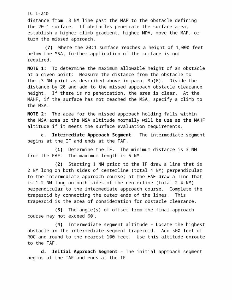
TC 1-240i. Supporting information and actions are sought from the crew. This quality
addresses the extent to which supporting information and actions are sought from the crew by another crew member, usually the PC. Crew members should feel free to raise questions during the flight regarding plans, revisions to plans, actions to be taken, and the status of key mission information. Specific goals include the following.
(1) The PC encourages crew members to raise issues or offer information about safety or the mission. Crew members anticipate impending decisions and actions and offer information as appropriate.
(2) Crew members always request assistance from others before they become overloaded with tasks or before they must divert their attention from a critical task.
j. Crew member actions are mutually cross-monitored. This quality addresses the extent to which a crew uses cross-monitoring as a mechanism for breaking error chains that lead to accidents or degraded mission performance. Crew members must be capable of detecting each other's errors. Such redundancy is particularly important when crews are tired or overly focused on critical task elements and thus more prone to make errors. Specific goals include the following.
(1) Crew members acknowledge that crew error is a common occurrence and the active involvement of the entire crew is required to detect and break the error chains that lead to accidents. They constantly watch for crew errors affecting flight safety or mission performance. They monitor their own performance as well as that of others. When they note an error, they quickly and professionally inform and assist the crew member committing the error.
(2) The crew thoroughly discusses the two-challenge rule before executing the mission. When required, they effectively implement the two-challenge rule with minimal compromise to flight safety.
NOTE: The two-challenge rule allows one crew member to automatically assume the duties of another crew member who fails to respond to two consecutive challenges. For example, the P* becomes fixated, confused, task overloaded, or otherwise allows the aircraft to enter an unsafe position or attitude. The P first asks the P* if he is aware of the aircraft position or attitude. If the P* does not acknowledge this challenge, the P issues a second challenge. If the P* fails to acknowledge the second challenge, the P assumes control of the aircraft.
k. Supporting information and actions are offered by the crew. This quality addresses the extent to which crew members anticipate and offer supporting information and actions to the decision maker--usually the PC--when apparently a decision must be made or an action taken. Specific goals include the following.
(1) Crew members anticipate the need to provide information or warnings to the PC or P* during critical phases of the flight. They provide the required information and warnings in a timely manner.
(2) Crew members anticipate the need to assist the PC or P* during critical phases of flight. They provide the required assistance when needed.
l. Advocacy and assertion are practiced. This quality concerns the extent to which crew members are proactive in advocating a course of action they consider best, even when others may disagree. Specific goals include the following.
(1) While maintaining a professional atmosphere, crew members state the rationale for their recommended plans and courses of action when time permits. They request feedback to make sure others have correctly understood their statements or rationale. Time
6-5
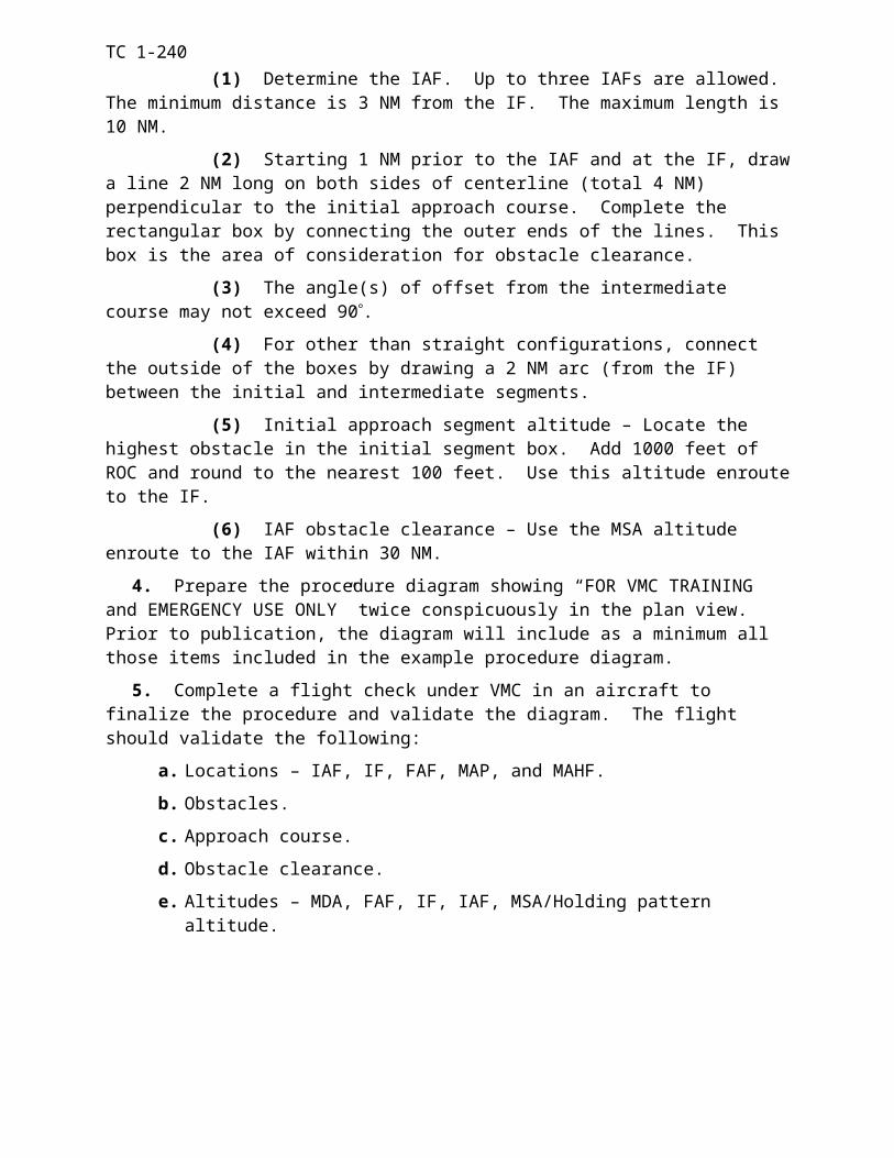
TC 1-240permitting, other crew members practice good listening habits; they wait for the rationale before commenting on the recommended plans or courses of action.
(2) The PC actively promotes objectivity in the cockpit by encouraging other crew members to speak up despite their rank or experience. Junior crew members do not hesitate to speak up when they disagree with senior members; they understand that more experienced aviators can sometimes commit errors or lose situational awareness. Every member of the crew displays a sense of responsibility for adhering to flight regulations, operating procedures, and safety standards.
m. Crew-level after-action reviews are conducted. This quality addresses the extent to which crew members review and critique their actions during or after a mission segment, during periods of low workload, or during the mission debriefing. Specific goals include the following:
(1) The crew critiques major decisions and actions. They identify options and factors that should have been discussed and outline ways to improve crew performance in future missions.
(2) The critique of crew decisions and actions is professional. "Finger pointing" is avoided; the emphasis is on education and improvement of crew performance.
6-4 CREW COORDINATION OBJECTIVES
The crew coordination elements and basic qualities are measured to determine if the objectives of the crew coordination program have been met. The objectives of the program have been defined by five crew coordination objectives. The five objectives are as follows.
a. Establish and maintain team relationships. Establish a positive working relationship that allows the crew to communicate openly and freely and to operate in a concerted manner.
b. Mission planning and rehearsal. Explore, in concert, all aspects of the assigned mission and analyze each segment for potential difficulties and possible reactions in terms of the commander's intent.
c. Establish and maintain workloads. Manage and execute the mission workload in an effective and efficient manner with the redistribution of task responsibilities as the mission situation changes.
d. Exchange mission information. Establish intra-crew communications using effective patterns and techniques that allow for the flow of essential data between crew members.
e. Cross-monitor performance. Cross-monitor each other's actions and decisions to reduce the likelihood of errors impacting mission performance and safety.
6-5. STANDARD CREW TERMINOLOGY
To enhance communication and crew coordination, crews should use words or phrases that are understood by all participants. They must use clear, concise terms that can be easily understood and complied with in an environment full of distractions. Multiple terms with the same meaning should be avoided. DOD FLIP contains standard terminology for radio communications. Operator's manuals contain standard terminology for items of equipment.
Figure 6-1 is a list of other standard words and phrases that crew members may use.6-6
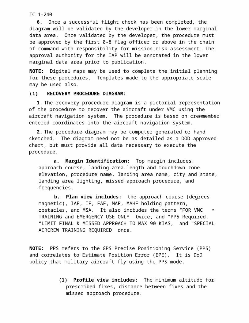
TC 1-240
6-7
Abort- terminate a preplanned aircraft maneuver.Affirmative – yes.Bandit - an identified enemy aircraft.Blocking – announcement made by the crew member who intends to block the pedals. Bogey - an unidentified aircraft assumed to be enemy.Braking – announcement made by the RCM who intends to apply brake pressure.Break – immediate action command to perform a maneuver to deviate from the present ground track - will be followed by "right," "left."Call out - command by the P* for a specified procedure to be read from the checklist by another crew member.Cease-fire - command to stop firing but continue to track.Clear - no obstacle present to impede aircraft movement along the intended ground track. Will be preceded by the word "nose," "tail," or "aircraft" and followed by a direction; for example, "right" or "slide left." Also indicates that ground personnel are clear to approach the aircraft.Come up/down - command to change altitude up or down.Contact – establish communication with….(followed by the name of the element).Controls – refers to the aircraft flight controlsCorrect - confirms a statement as being accurate or right. Do not use the word "right" to indicate correct.Drifting - an alert of the unannounced movement of the aircraft; will be followed by direction.Egress - immediate action command to get out of the aircraft.Execute - initiate an action.Expect - anticipate further instructions or guidance.Fire light - announcement of illumination of the master fire warning light. Firing - announcement that a specific weapon is to be fired.Go ahead – proceed with your message.Go plain/red - command to discontinue secure operations.Go secure/green - command to activate secure operations.Hold - command to maintain present position. I have the controls - used as a command or announcement by the RCM assuming control of the flight controls.Inside - primary focus of attention is inside the aircraft.In sight - preceded by the word "traffic," "target, " "obstacle," or descriptive term. Used to confirm the traffic, target, or obstacle is positively seen or identified.Jettison - command for emergency release of an external load or stores; when followed by "door," indicates the requirement to perform emergency door removal.Maintain - command to keep or continue the same.Mask - command to conceal aircraft.Mickey – have quick time synchronized signal.Monitor – command to maintain constant watch or observation. Move forward/backward - command to hover the aircraft forward or backward; followed by distance. Also used to announce intended forward or backward movement.Negative – incorrect or permission not granted.Negative contact – unable to establish communication with…(followed by the name of the element).No joy – target traffic or obstacle not positively seen or identified.Now – indicates that an immediate action is required.Outside – primary focus of attention is outside the aircraft. Put me up - command to place a frequency in a specific radio.Release - command for the planned release of an external load.Report - command to notify.Right - used to indicate a direction only, not to be used in place of "correct."Roger – message received and understood.Say again – repeat your transmission.Slide left/right - command to hover the aircraft left or right; will be followed by distance. Also used to announce intended left or right movement.Slow down - command to decrease ground speed.Speed up - command to increase ground speed.
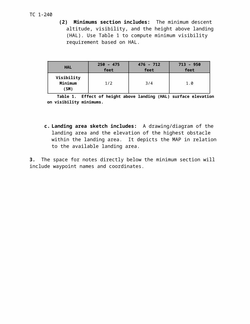
TC 1-240
Figure 6-1. Standard words and phrases
6-8
Stand by – wait: duties of a higher priority are being performed and the request cannot be complied with at this time.Stop - command to go no further; halt present action.Strobe - indicates that the AN/APR-39 has detected a radar threat; will be followed by a clock position.Talley – target traffic or obstacle positively seen or identified; will be followed by a repeat of the word target traffic or obstacle and the clock position.Target - an alert that a ground target has been spotted.Traffic - refers to any friendly aircraft that presents a collision hazard; will be followed by a clock position, distance, and reference to altitude.Troops on/off - command for troops to enter/exit the aircraft.Turn - command to deviate from the current heading; will be followed by the word "right" or "left" and a specific heading or rally term.Unable – indicates the inability to comply with a specific instruction or request.Unmask - command to position the aircraft above terrain features.Up on - indicates the radio selected; will be followed by the position number on the ICS panel; for example, "Up on 3."Weapons hot/cold/off - indicates weapon switches are in the ARMED, SAFE, or OFF position.Wilco – I have received your message and I understand and will comply.You have the controls - used as a command or announcement by the RCM relinquishing the flight controls.
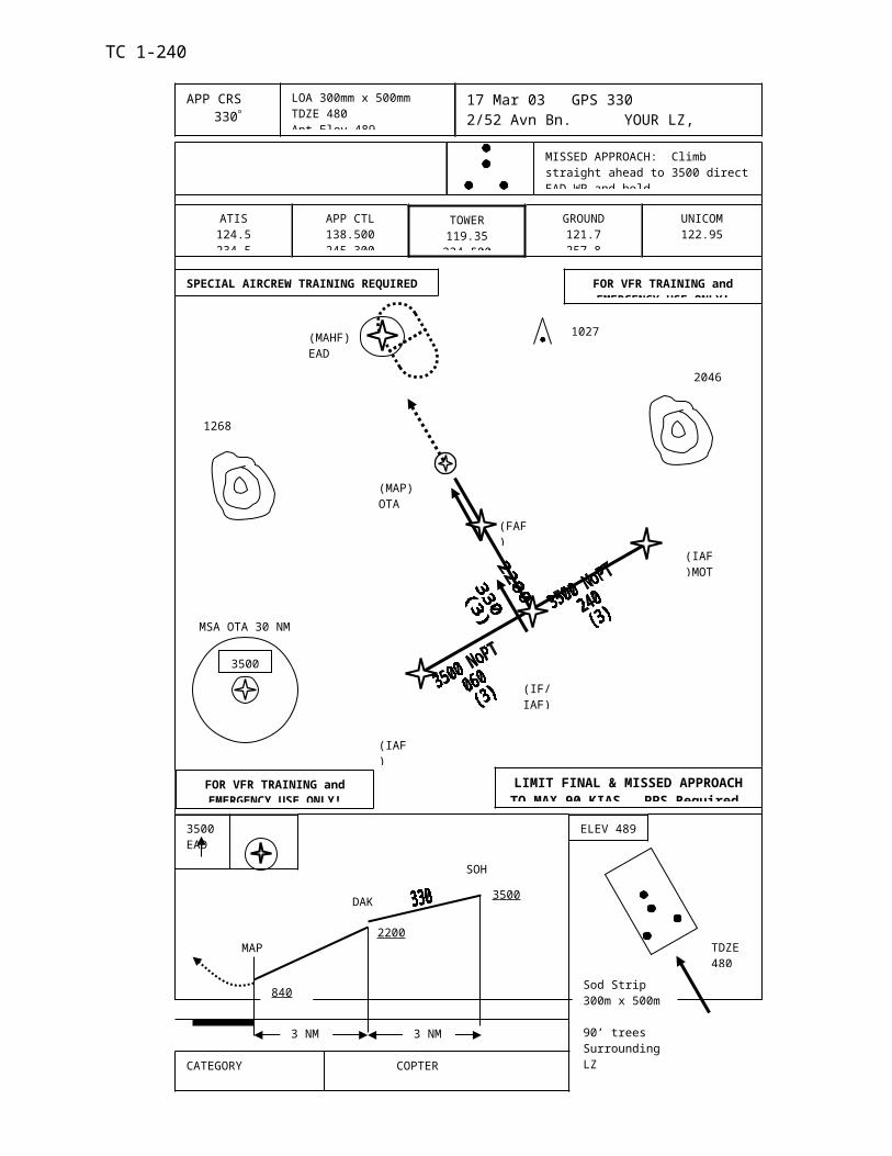
TC 1-240 APPENDIX A SECTION I
NONRATED CREW MEMBER (NCM) TRAINING & QUALIFICATION
A-1. NCM AIRCRAFT QUALIFICATION TRAINING. MOS qualification is conducted at DA-approved training sites. Crew chiefs must complete aircraft qualification training listed below. Figure A-1 describes the required system subjects, Figure A-2 describes the required academic subjects, and Figure A-3 describes the flight training subjects for 15U’s. Chapter 2 Figure 2-4 lists the individual base task training requirements, Figure A-4 outlines flight training hour requirements, and Figure A-5 outlines a recommended flight training sequence.
a. Academic Qualification Training. The NCM must receive sufficient instruction to be knowledgeable in the academic, system, and flight-training subjects listed below. Academic instruction will be IAW NCM ETP 2C-011-0002-A. The academic instruction may be completed in any order, but must be completed (to include the examination) and documented in the IATF on DA Form 7122-R prior to flight training. The academic classes are mandatory but the hour requirements are based on crew member retention. Commanders will develop a 50-question open book written examination covering the subject areas listed in this Appendix. Crew members must pass the examinations with a grade of at least 70 percent.
SYSTEM SUBJECTSAircraft systems, structure, and Airframe. Maintenance forms and records.Avionics and mission equipment. Weight and balance.Flight control hydraulic system. Electrical system.Power plant and related systems. Flight control system.Auxiliary power unit (APU). Rotor systemTransmission and drive systems. Fuel and oil systems.Landing gear, wheels, and brake systems. Environmental systems.Utility systems. Prepare aircraft for preflight.Inspection requirements. Cargo winching and loading.Aircraft Limitations Cargo tie-down and storage.Advanced flight control system. Armaments subsystems.Aircraft Mooring Refueling operationsMaintenance manual written examinationMalfunction analysis (emergency procedures) written examinationSystem subject written examination
Figure A-1. System subjects
Appendix A-1

TC 1-240
ACADEMIC SUBJECTSAeromedical factors DA regulation and publicationsAviation Life Support Equipment (ALSE) Passenger briefingsUnit SOPs and local regulations. Aircrew training program introductionHand and Arm signals ATM IntroductionLogbook and forms. In-flight duties.Crew mission briefing. Confined area and slope operations.Engine start-through-before takeoff checks. Aircraft refueling procedures.External load operations. Internal load operations.Crew coordination training/qualification Armament system/operations.Environmental operations. Aircraft survivability equipment.Academic subject written examination Operating limits and restrictionsNight mission operations and deployment Emergency Procedures
Figure A-2. Academic subjects
FLIGHT TRAINING SUBJECTSOperating limitations and restrictions In-flight dutiesInternal/External load operations Radio communication proceduresStart and run-up procedures Before takeoff checksHit check procedures Refueling procedures.Confine area and slope operations. Aircraft survivability equipment.Clearing aircraft during flight Environmental operationsPreflight procedures Egress proceduresFlight training subject written examination
Figure A-3. Flight training academic subjects.
b. Flight Training. The NCM will be required to demonstrate proficiency in all individual base tasks listed in Chapter 2, Figure 2-4 and demonstrate crew coordination and airspace surveillance proficiency. An X in the night column of Chapter 2, Figure 2-4 identifies night tasks required for qualification training. Flight training consists of 13 hours in the aircraft. The commander may reduce the total flight time shown in Figure A-4 to no less than 10 hours based on a recommendation from the SP, IP, SI, or FI. Table A-5 shows recommended flight time allotted for each training day.
Flight Instruction Flying Hours
Preflight tasks1 0.0Run-up tasks1 0.0Base tasks2 9.0Emergency procedures3 2.0After-landing tasks1 0.0Evaluation4 2.0Total hours 13.0
1 These tasks are considered flight instruction, although flight time is not logged.2A minimum of one hour will be at night.3 Emergency procedures required in each mode of flight4 The evaluation may be a continual evaluation.
Figure A-4. Flight training for NCMs.
Appendix A-2
TC 1-240 FLIGHT TRAINING SEQUENCE
TNG DAY 1 2 3 4* 5DAILY 2.5 2.5 2.5 2.5 3.0ECUM TIME 2.5 5.0 7.5 10 13.0NOTE. * Denotes Night flight
Figure A-5. Recommended flight training sequence.
c. Documentation. Upon completion of training an entry will be made in the remarks section of DA Form 7122-R of the NCMs IATF. At the NCM’s next closeout, training will be documented in Part V, Remarks section, of the crew member’s DA Form 759. A separate entry in the closeout is required for aircraft qualification training completion.
A-2. NVG QUALIFICATION. NVG qualification will be accomplished per Chapter 2, paragraph 2-1b.
A-3. REFRESHER TRAINING. Refresher training will be accomplished per Chapter 2, paragraph 2-2.
A-4. MISSION TRAINING. Mission training will be accomplished per Chapter 2, paragraph 2-3.
A-5. CONTINUATION TRAINING. Continuation training will be accomplished per Chapter 2, paragraph 2-4.
A-6. NBC TRAINING. NBC training will be accomplished per Chapter 2, paragraph 2-6.
Appendix A-3
TC 1-240 SECTION II
STANDARDIZATION INSTRUCTOR (SI), FLIGHT ENGINEER INSTRUCTOR (FI), AND NONRATED CREW MEMBER TRAINER (NCT) TRAINING &
QUALIFICATION
A-7. QUALIFICATION TRAINING
a. SI/FI training/qualification.
(1) Prerequisites for FI qualification. 15U Nonrated crew member in the rank of SGT through SSG with a minimum of one year experience as a CH47 Flight Engineer (FE), possess a current flight physical, and be on crew member orders.
(2) Initial FI training. This training is conducted at USAAVNC, Ft. Rucker AL. Initial validation of a crew member’s qualification following this course of instruction and at each new duty station will be conducted in the aircraft by an SP, IP, or SI. Additional academic and flight hour requirements are at the discretion of the unit commander.
(3) SI qualification. An SI must be an FI and it is recommended that the SI have a minimum of one year experience as a CH47 FI. The SI must be able to supervise and implement the commander’s ATP for nonrated crew members and assist the unit SP with the supervision and maintenance of the standardization program.
(4) Documentation. Upon completion SI/FI qualification training and evaluation the SP/IP/SI/FI (as appropriate) will enter the recommendation made in the remarks section DA Form 7122 of the NCM’s IATF and get the commander’s written approval. At the NCM’s next closeout, training will be documented in Part V, Remarks section, of the crew member’s DA Form 759.
b. Nonrated Crew member Trainer (NCT) training/qualification. The NCT was created to lessen the training burden on the FIs/SIs by letting them instruct RL2/RL1 crew members on certain task(s) that they show an expert knowledge in. It was not created to make additional FIs/SIs. Once designated as an NCT, he may conduct FE duties or conduct training in the mission/additional task(s) that he is designated to instruct. NCTs will not conduct training on RL3 crew members, nor will they perform evaluations.
NOTE: The goal should not be to make all FEs into NCTs in all mission/additional tasks, but rather to give the FEs the ability to instruct task(s) in which they are subject matter experts.
(1) Prerequisite’s for Nonrated Crew member Trainer (NCT) qualification. The unit commander is responsible for conducting NCT qualification IAW this ATM. Recommended Active Army, NGR, and Reserve component personnel in grade of SPC through SSG, must be a current CH47 RL 1 Flight Engineer (FE), must possess a current flight physical, and be on crew member orders.
(2) Academic training. Academic training will be conducted at the unit level. The NCM must receive sufficient instruction to possess the ability to demonstrate proper Method of Instruction (MOI) and be knowledgeable in the mission/additional task(s) he is designated to instruct. He must be able to effectively impart that knowledge unto an RL2 crew member.
Appendix A-4
TC 1-240
(3) Flight Training. The NCT will be evaluated on his ability to perform, train, and MOI the specific mission/additional task(s) in which he is designated to instruct. He will be required to demonstrate Method of Instruction (MOI) proficiency in task(s) designated and must also be able to instruct crew coordination and airspace surveillance in those task(s). Performance will be considered unsatisfactory when the task is not performed within the standards or an unsafe condition exists which requires the instructor to intercede to ensure safety of the aircraft and/or occupants. All flight tasks will be performed to proficiency.
(4) Documentation. Upon completion of the NCT qualification training and evaluation the SP/IP/SI/FI (as appropriate) will enter the recommendation made in the remarks section DA Form 7122 of the NCMs IATF and get the commander’s written approval. At the NCMs next closeout, training will be documented in Part V, Remarks section, of the crew member’s DA Form 759.
Appendix A-5
TC 1-240
Intentionally left blank.
Appendix A-6
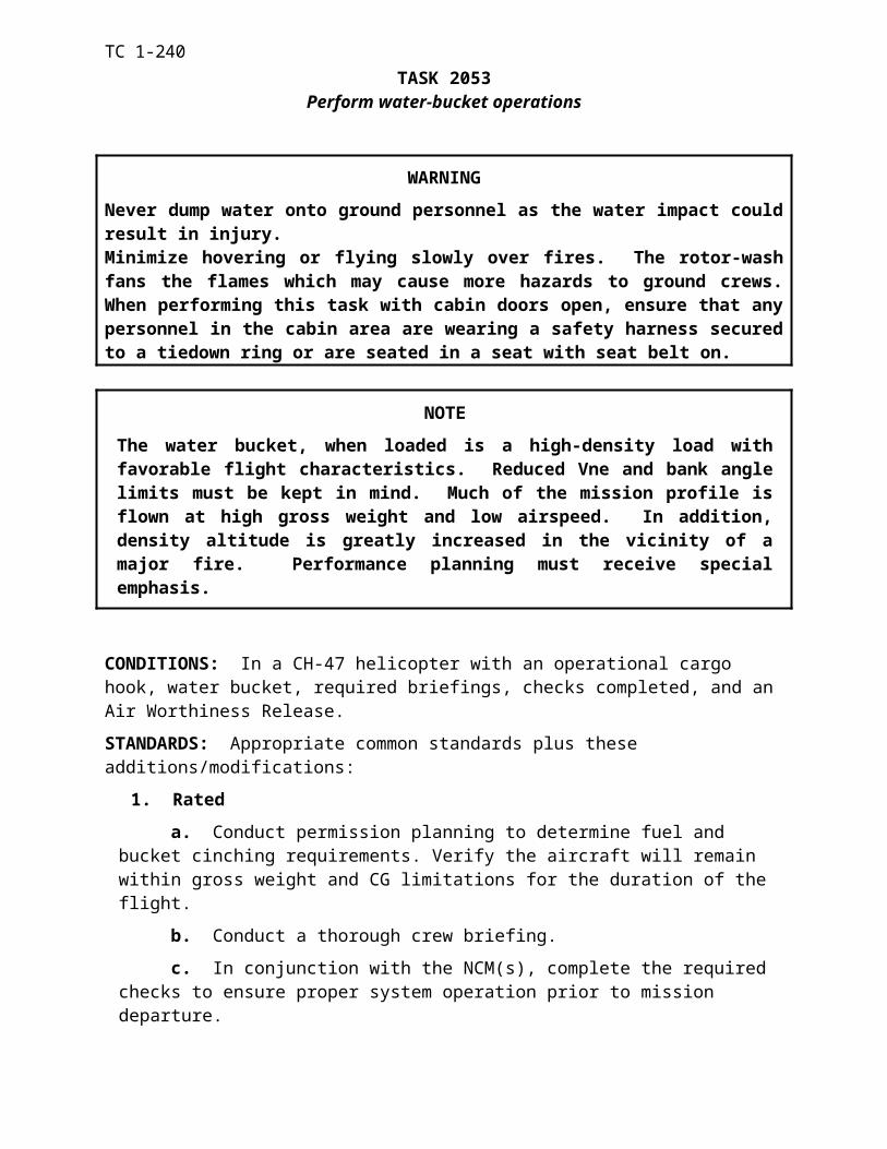
TC 1-240
APPENDIX B
Heads-Up Display (HUD)B-1. GENERAL. HUD qualification will be conducted IAW this ATM or applicable POI. HUD qualified UTs, IPs, or SPs will conduct academic training and flight training. A HUD qualified IP or SP will conduct the flight evaluations. Qualification must be completed within 90 days.
B-2. QUALIFICATION TRAINING. Qualification training will provide the aviators with the knowledge, skills and techniques required to integrate HUD operations into NVG flight. Train-ing in the aircraft will be with the aviator at a station with access to the flight controls, wearing ANVIS with HUD attached. A HUD qualified IP, SP, or UT will be at the other station with ac-cess to the flight controls. HUD qualification training may be conducted concurrently during NVG qualification, refresher and mission training.
NOTE 1: Academic training and training flights may be conducted by an NVG UT designated by the commander to conduct HUD training. When flight training is conducted by a UT the trainee must be designated at least NVG RL2. A HUD-qualified NVG IP/SP must conduct the evaluation.
NOTE 2: Once qualified, the RCM has no currency requirements for HUD operations unless specified by the commander. One RCM may fly with the HUD and the other without. There is no requirement for both RCMs to fly with the HUD, unless specified by the commander. Academic training must be completed before flight training begins.
B-3. ACADEMIC TRAINING. Using the NVG TSP that incorporates HUD academic training or the HUD Computer Based Trainer (CBT), the trainee will receive instruction in the following subject areas:
a. AN/AVS-7 HUD system components.
b. HUD symbology.
c. HUD system operations (programming, adjusting, and operating).
B-4. FLIGHT TRAINING. This program outlines the minimum flight hour requirements for HUD qualification. Some RCMs may require additional flight periods to achieve a satisfactory level of proficiency with the ANVIS HUD. Because initial HUD training can cause the aviator to be distracted, the NCM should be stationed on the same side of the aircraft as the aviator re-ceiving training. HUD training requires the RCM to develop new scanning habits. Time must be allowed to absorb this new information and develop new scan patterns. Therefore, training days will not be combined. Each training day involving aircraft flights will be completed in sequence on separate nights.
NOTE 1: Training Day 1 includes 1.0 hour of static aircraft HUD training concentrating on pro-gramming. The 1.0 hour of static aircraft training in programming and operations must be com-pleted prior to the first flight. Training day 1 and 2 may be completed in the aircraft or SFTS. Hours indicated in the above table denote the minimum hours per flight training period. Flight training periods will not be reduced. The program in figure B-1 gives the minimum required flight training for qualification.
Appendix B-1
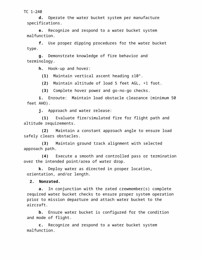
TC 1-240
Training Day 1 2 3 4Aircraft 1.0 1.0 1.0Static Training 1.0Cumulative 1.0 2.0 3.0 4.0
Figure B-1. HUD Training program
B-5. TRAINING DOCUMENTATION. After crewmembers complete AN/AVS-7 initial qualification, units will ensure that an entry is made on the crewmember's DA Form 7122-R and transcribed to the DA Form 759.
Appendix B-2
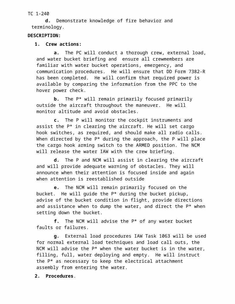
TC 1-240
APPENDIX CSECTION I
T55-L-712 QUALIFICATION TRAINING
C-1. GENERAL: T55-L-712 qualifications will be conducted locally IAW the Operators Manual, this ATM, or the equipment manufacturers instructions, as appropriate. Upon completion of training an entry will be made on DA Form 7122, Crew member Training Record. At the aviator’s next closeout, the qualification will be documented in Part V, Remarks section, of the crew member’s DA Form 759.
C-2. PREREQUISITES
a. SOP. A unit SOP is not required for this training.
b. Previous Qualifications.
(1) Rated crew members. Must be rated in CH-47 aircraft equipped with T55-GA-714.
(2) Non-rated crew members. Must be qualified as a 15U crew member.
c. Conditions. No special conditions are specified for this training.
d. Personnel Requirements. Personnel assigned to units that are equipped with aircraft fitted with T55-L-712 engines must be qualified IAW this Appendix.
e. Equipment Requirements. Aircraft modified with T55-L-712 engines, and current publications are required for this training
f. Readiness Level. Crew members undergoing this training are RL3 until the training is completed if the unit aircraft are equipped exclusively with T55-L-712 engines. If the unit has aircraft modified with both T55-GA-714 and T55-L-712 engines, the crew members RL status will not change while undergoing this training.
C-3. ACADEMIC TRAINING
a. Training Material. The following publications are required to conduct this training.
(1) TC 1-240, CH-47 Aircrew Training Manual Cargo Helicopter
(2) TM 1-1520-240-10, CH-47 Operators Manual
(3) TM 1-1520-240-CL, Operator/Crew member Checklist
(4) TM 1-1520-240-PMD, Preventative Maintenance Daily
(5) TM 1-1520-240-MTF, Maintenance Test Flight Manual
(6) TM 1-1520-240-PM, Phased Maintenance Checklist
(7) TM 1-1520-240-23 series, Maintenance Manual
(8) TM 1-1520-240-23P series, Parts Manual
Appendix C-1
TC 1-240
b. Authorized Academic Trainers. All trainers must be T55-L-712 qualified prior to conducting training. Authorized trainers are any: SP, IP, ME, SI, or FI and can train any: CE, FE, FI, SI, UT, PI, PC, IP, and SP.
c. Academic Content. The training should as a minimum cover the following topics.
(1) Comprehensive publications overview.
(2) T55-GA-714 and T55-L-712 general characteristics and differences.
(3) Associated limitations and emergency procedures.
(4) T55-L-712 specific maintenance task for CEs, FEs, FIs, and SIs.
NOTE: Academic training must be completed before the start of flight training.
C-4. FLIGHT TRAINING
a. Minimum Hours. The minimum hours for qualification are as detailed below.
(1) PI and PC – 1.5 Hours (Two separate flights, the first flight in the right seat and the second flight in the left seat).
(2) CE, FE, FI and SI – 1.5 Hours
(3) IP and SP – 1.0 hour in addition to (1) above (This flight will concentrate on emergency procedure training).
(4) MP and ME – N/A
NOTE: Flight time in the aircraft may be reduced by 50% with the use of a CH-47D FS with T55-L-712 incorporated simulation.
b. Minimum Tasks. The minimum tasks for qualification training are as detailed below.
(1) PI, PC, IP and SP Tasks
(a) Prepare PPC
(b) Perform preflight inspection
(c) Perform Before-Starting Engine through Before-Leaving Helicopter checks
(d) Health indication test (HIT)
(e) Perform hover power check
(f) Perform emergency procedures
(2) CE, FE, FI and SI Tasks
(a) Perform preflight inspection
(b) Perform Before-Starting Engine through Before-Leaving Helicopter checks
(c) Perform emergency procedures
(d) Health indication test (HIT)
(3) MP and ME Tasks - Incorporated in the USAAVNC CH-47 MTPC
c. Authorized Trainers
(1) SI/FI – Can train; CE, FE, FI, and SI.
Appendix C-2
TC 1-240
(2) SP/ IP – Can train; CE, FE, FI, SI, PI,PC, IP and SP.
(3) ME – N/A
C-5. EVALUATIONS
a. Qualification. End of training evaluation or a continuous evaluation.
b. Annual. No annual evaluation is required.
c. Currency. No currency evaluation is required.
d. Authorized Evaluators.
(1) FI – Can evaluate; CE or FE.
(2) SI – Can evaluate; CE, FE, FI, and SI.
(3) IP – Can evaluate; CE, FE, FI, SI, PI, and PC
(4) SP – Can evaluate; CE, FE, FI, SI, PI, PC, IP and SP.
(5) ME – Can evaluate; MP and ME.
Appendix C-3
TC 1-240
SECTION II
T55-GA-714 QUALIFICATION TRAINING
C-6. GENERAL: T55-GA-714 qualifications will be conducted locally IAW the Initial System Training (IST), the Airworthiness Release (AWR), the Interim Statement of Airworthiness Qualification, the Training Support Package (TSP), the Operators Manual, this ATM, or the equipment manufacturers instructions, as appropriate. Upon completion of training an entry will be made on DA Form 7122, Crew member Training Record. At the aviator’s next closeout, the qualification will be documented in Part V, Remarks section, of the crew member’s DA Form 759.
C-7. PREREQUISITES
a. SOP. A unit SOP is not required for this training.
b. Previous Qualifications.
(1) Rated crew members. Must be rated in CH-47 aircraft equipped with T55-L-712 engines.
(2) Non rated crew members. Must be qualified as a 15U crew member.
c. Conditions. No special conditions are specified for this training.
d. Personnel Requirements. Personnel assigned to units that are equipped with aircraft fitted with T55-GA-714 engines must be qualified IAW this Appendix.
e. Equipment Requirements. Aircraft modified with T55-GA-714 engines, Electronic Torque-meter Flight Line Test Set, Soldier’s Portable On-System Repair Tool (SPORTS) computer, and current publications are required for this training.
f. Readiness Level. Crew members undergoing this training are RL3 until the training is completed if the unit aircraft are equipped exclusively with T55-GA-714 engines. If the unit has aircraft modified with both T55-L-712 and T55-GA-714 engines, the crew members RL status will not change while undergoing this training.
C-8. ACADEMIC TRAINING
a. Training Material. The following publications are required to conduct this training.
(1) Eastern ARNG Aviation Training Site (EAATS) T55-GA-714 Initial System Training manual, 13 DEC 99 Ver 2.0 or later, or the most current version available on CD for Computer Based Training (CBT).
(2) TC 1-240, CH-47 Aircrew Training Manual Cargo Helicopter
(3) TM 1-1520-240-10, CH-47 Operators Manual
(4) TM 1-1520-240-CL, Operator/Crew member Checklist
(5) TM 1-1520-240-PMD, Preventative Maintenance Daily
Appendix C-4
TC 1-240
(6) TM 1-1520-240-MTF, Maintenance Test Flight Manual
(7) TM 1-1520-240-PM, Phased Maintenance Checklist
(8) TM 1-1520-240-23 series, Maintenance Manual
(9) TM 1-1520-240-23P series, Parts Manual
b. Authorized Trainers. All trainers must be T55-GA-714 qualified prior to conducting training.
(1) NCT/FI/SI – Can train; CE, FE, NCT, FI and SI.
(2) UT/IP/SP/ME – Can train; CE, FE, NCT, FI, SI, UT, PI, PC, IP, SP, MP, and ME.
c. Academic Content. The training should as a minimum cover the following topics.
(1) Comprehensive publications overview.
(2) T55-L-712 and T55-GA-714 general characteristics and differences.
(3) Full Authority Digital Electronic Control (FADEC) description and components.
(4) Associated limitations and emergency procedures.
(5) T55-GA-714 specific maintenance task for CEs, FEs, FIs, SIs, MPs, and MEs.
NOTE: Academic training must be completed before the start of flight training.
C-9. FLIGHT TRAINING
a. Minimum Hours. The minimum hours for qualification are as detailed below.
(1) PI and PC – 1.5 Hours (Two separate flights, the first flight in the right seat and the second flight in the left seat).
(2) CE, FE, FI and SI – 1.5 Hours.
(3) IP and SP – 1.0 hour in addition to (1) above (Third flight concentrating on emergency procedure training)
(4) MP and ME – 1.0 hour in addition to (1) above (Third flight concentrating on maintenance test flight tasks in the left seat conducted by a ME)
b. Minimum Tasks. The minimum tasks for qualification training are as detailed below.
(1) PI, PC, IP and SP Tasks
(a) Prepare PPC
(b) Perform preflight inspection
(c) Perform before-starting engine through before-leaving helicopter checks
(d) Perform PAT check
(e) Perform hover power check
(f) Perform emergency procedures
(2) CE, FE, FI and SI Tasks
(a) Perform preflight inspection
Appendix C-5
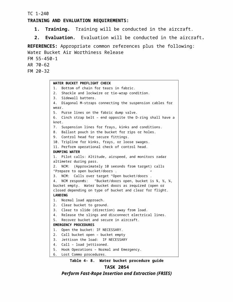
TC 1-240
(b) Perform before-starting engine through before-leaving helicopter checks
(c) Perform PAT check
(d) Perform emergency procedures
(3) MP and ME Tasks
(a) PI, PC, IP and SP Task plus the following
(b) Perform starting engine checks (714)
(c) Perform electrical system checks
(d) Perform power assurance check (714)
(e) Perform droop eliminator check
(f) Perform self-tuning vibration absorber check
(g) Perform RRPM droop check and thrust rod slippage check
(h) Perform auto-rotational RPM check
(i) Perform power assurance test
(j) Perform DECU start bit check
(k) Perform FADEC system check
(l) Perform P3 bellows check
(m) Perform PTIT load share check
(n) Perform torque differential check
(o) Develop a trigger value
c. Authorized Trainers.
(1) FI/SI – Can train; CE, FE, FI, and SI.
(2) IP/SP – Can train; CE, FE, FI, SI, PI, PC, IP, and SP.
(3) ME – Can train; MP and ME. (The MP or ME candidate must be T55-GA-714 qualified as a PI or PC prior to receiving maintenance tasks training from the ME).
C-10. EVALUATIONS
a. Qualification. End of training evaluation or a continuous evaluation.
b. Annual. No annual evaluation is required.
c. Currency. No currency evaluation is required.
d. Authorized Evaluators.
(1) FI – Can evaluate; CE or FE.
(2) SI – Can evaluate; CE, FE, FI, and SI.
(3) IP – Can evaluate; CE, FE, FI, SI, PI, and PC
(4) SP – Can evaluate; CE, FE, FI, SI, PI, PC, IP and SP.
Appendix C-6
TC 1-240
(5) ME – Can evaluate; MP and ME.
NOTE: T55-GA-714A qualifications training for crewmembers previously qualified in the T55-L-714 engine consist of academic training concentrating on engine differences. There is no flight-training requirement for T55-GA-714A qualification if previously T55-L-714 qualified. Once the academic training is complete, the qualification will be documented on the DA Form 7122 and in the remarks section of DA Form 759 as previously stated.
Appendix C-7
TC 1-240
Intentionally left blank.
Appendix C-8
TC 1-240
APPENDIX D
INSTRUCTOR PILOT SUPPLEMENTAL INFORMATION
D-1. EMERGENCY PROCEDURES TRAINING
a. The following procedures will not be performed in the aircraft except in the event of an actual emergency:
Touchdown autorotation.
Running landing to water.
Single-engine takeoff from the ground.
Actual engine stoppage in-flight or during taxi.
Power Transfer Unit switches “ON” or number 1 or number 2 hydraulic control switches out of the “both” position during taxiing or flight.
Both engine condition levers out of the flight position during taxiing or flight.
Bus-tie relay disabled or gang bar placed down.
APU operations during taxiing or flight.
Jettison of external load.
Emergency descent.
Dual FADEC Primary and/or Reversionary failure (May be performed by authorized trainers at USAAVNC and DA approved training sites and by qualified trainers during individual 714 qualifications).
ECL out of flight position with other engine FADEC switch in Reversionary.
Engine shutdown with APU inoperative.
Dual generator failure.
Dual Rectifier failure.
AFCS-OFF external load hook-up.
b. In addition to the emergency procedures listed in paragraph F2 below, SPs/IPs may also demonstrate:
(1) Cargo hook manual release.
(2) Cargo hook pneumatic release if the pre-charge is low and requires servicing.
c. The emergency procedures listed herein are demonstrated, practiced, and evaluated during training. Any emergency procedure may be simulated and the procedure performed in the CH-47FS.
Appendix D-1
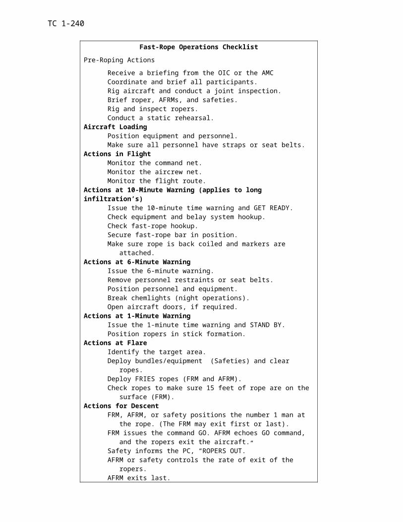
TC 1-240
d. Aircraft emergency conditions, procedures, restrictions, and the only authorized methods of simulating the condition in the aircraft are:
D-2. INSTRUCTOR PILOT TECHNIQUES
a. Autorotate
(1) Conditions: May only be performed in the CH-47FS.
(2) Simulation: N/A
b. Emergency engine shutdown
(1) Condition: Initiated with the ECL in the ground detent and the required engine cool down met.
(2) Simulation: A verbal description of the procedure should accompany the single engine failure emergency procedure (time permitting). May not be performed during taxi or flight except in the CH47FS.
c. Abort start
(1) Conditions: Initiated during the engine start sequence or when the aircraft is parked, brakes set, ECL in the ground detent, and the required engine cool down met.
(2) Simulation: Verbally direct the crew member to abort the start, or initiate at the instructor/operator station (IOS) of the CH-47FS. May also utilize the FE/CE to verbally state conditions requiring the engine start to be aborted.
d. Dual Engine Failure
(1) Conditions: May only be performed in the CH-47FS.
(2) Simulation: Initiate at the instructor/operator station (IOS) of the CH-47FS..
e. Single Engine Failure - Low Altitude/Low Airspeed and Cruise.
(1) Low Altitude/Low airspeed.
(a) Conditions: Performed when single-engine hover out-of-ground-effect capability exists. This condition may be simulated during external load operations in the aircraft if the cargo hook master switch
Appendix D-2
WARNING
Simulation of emergency conditions, other than verbal, in the actual aircraft will only be accomplished while the aircraft is operating in VMC.

TC 1-240
is OFF to prevent inadvertent load jettison. IP should be especially vigilant and be ready for to use of emergency release all as required when the master switch is off.
(b) Simulation:
a. 712 - Using ECL or Emergency Engine Trim switches to decrease N1 appropriately.
b. 714 - Using the ECL. The crew member should state the indications and the IP announces engine failure or states the N1 is simulated below ground idle. Note - An associated ENG FAIL caution is associated with an actual engine failure.
(2) Takeoff
(a) Conditions: Performed anytime the aircraft is operating in a position over a suitable landing area to abort the takeoff, or operating above minimum single engine airspeed and above 100 feet AGL in a position to continue the takeoff single engine. This emergency condition will not be simulated during external load operations unless single engine hover out-of-ground effect capability exist.
(b) Simulation: Same as e. (1) (b) above.
(3) Cruise
(a) Conditions: Performed anytime the aircraft is above 200 feet AGL in a cruise profile. When conducting external load operations, the cargo hook master switch shall be off.
(b) Simulation: Same as e. (1) (b) above.
NOTE: When operating with only one engine on-line, that engine must remain in the primary FADEC mode of operation.
f. Engine Restart During Flight.
(1) Conditions: May only be performed in the CH47FS.
(2) Simulation: After a single engine failure the crew member should determine if it is feasible to perform an engine restart.
g. Normal Engine Beep Trim System Failure (High Side) or N2 Governor Failure.
(1) Conditions: Anytime. If external load operations are performed, the cargo hook master switch will be OFF.
(2) Simulation: Increase the rotor RPM using the No. 1 normal beep trim switch. Do not increase the rotor speed above 106 percent.
h. Normal Engine Beep Trim System Failure (Low Side or Static).
Appendix D-3
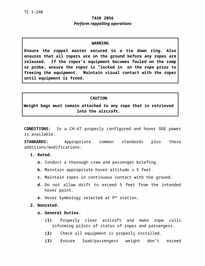
TC 1-240
(1) Conditions: Anytime. If external load operations are being performed, the cargo hook master switch shall be OFF.
(2) Simulation:
(a) Decrease the No. 1 normal beep trim switch then disable the normal engine trim or:
(b) Disable the No. 1 or No. 2 normal beep trim system and decrease the engine speed appropriately with the respective emergency engine trim switch.
NOTE: Disable normal trim by pulling the TRIM and Timer circuit breaker (A-17), or by placing the emergency engine trim auto/manual switch to the MANUAL position.
i. FADEC 1 or FADEC 2 Caution.
(1) Conditions: Anytime.
(2) Simulation: Place the appropriate PRI/REV switch to the REV position. It is important to ensure torque indicators are matched and operating RRPM is obtained prior to placing the switch again to the PRI position.
NOTE: For training purposes a FADEC system soft fault can be demonstrated by pulling the PRI CONT circuit breaker (A-7) on the appropriate PDP. This will be done only when the aircraft is on the ground prior to engine start, or at engine shutdown to demonstrate procedures for clearing soft faults. When operating with only one engine on-line that engine must remain in the primary FADEC mode of operation.
j. FADEC 1 and FADEC 2 Cautions.
(1) Conditions: May only be performed in the CH-47FS. (May be performed in the aircraft by authorized trainers at USAAVNC and DA approved training sites and by qualified trainers during individual 714 qualifications.)
(2) Simulation: Verbally describe indications. Place both No 1 and No 2 PRI/REV switches to REV.
k. 714 REV 1 and/or REV 2 (WITH) FADEC Light on.
(1) Conditions: May only be performed in the CH-47FS.
(2) Simulation: Verbally describe the indications.
l. 714 REV 1 and/or REV 2 (WITHOUT) FADEC Light on.
(1) Conditions: May only be performed in the CH-47FS.
(2) Simulation: Verbally describe the indications.
m. Torque Measuring System Malfunction.
Appendix D-4
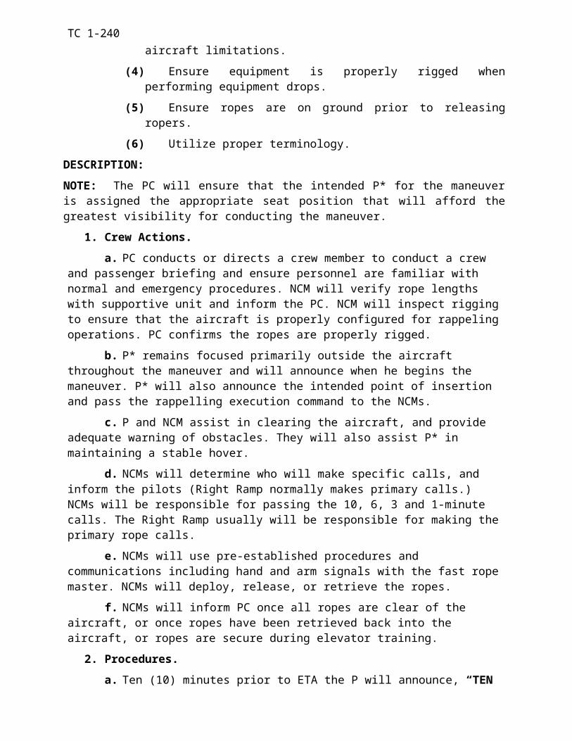
TC 1-240
(1) Conditions:(a) 712 - Anytime.
(b) 714 - May only be actually performed in the CH-47FS.
(2) Simulation: (a) 712 - Pull either (A-5) circuit breaker for associated power supply unit
or (A-15) circuit breaker for associated torque gauge.
(b) 714 – For training purposes a FADEC system soft fault can be demonstrated by pulling the DC TORQUE circuit breaker (A-5) on the appropriate PDP. This will be done only when the aircraft is on the ground prior to engine start, or at engine shutdown to demonstrate procedures for clearing soft faults.
n. Engine Transmission Clutch Failure to Engage.
(1) Conditions: Anytime.
(2) Simulation: Verbally state the indications.
o. Engine Shutdown - Complete Electrical Failure.
(1) Conditions: May only be performed in the CH-47FS.
(2) Simulation: Verbally state the indications.
p. Engine Shutdown - Condition Lever Failure.
(1) Conditions:
(a) 712 - Performed during shutdown after engine has stabilized in ground for two minutes.
(b) 714 - May only be performed in the CH-47FS.
(2) Simulation: (a) 712 - Disable engine-condition lever by pulling COND CONT circuit
breaker (A-8). (b) 714 - Verbally state the indications.
q. Engine Shutdown - With APU or APU Generator Inoperative.
(1) Conditions: May only be performed in the CH47FS.
(2) Simulation: Require the crew member to shutdown the engines after an APU or APU generator failure.
Appendix D-5
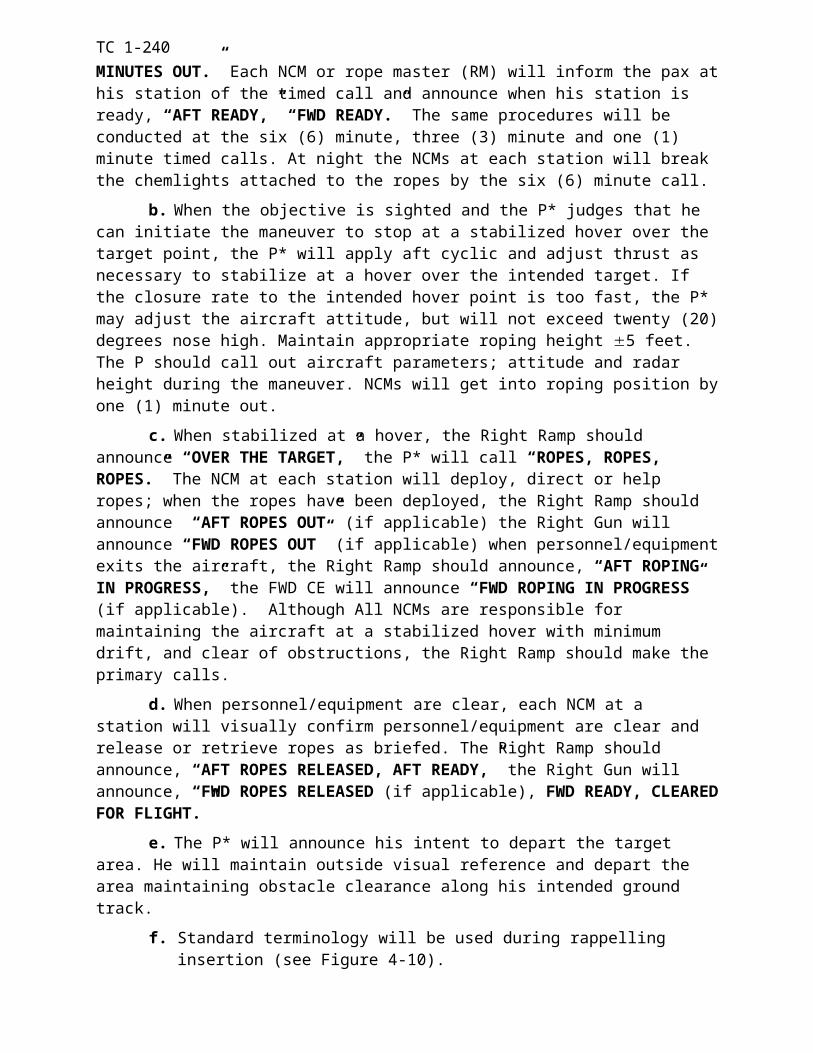
TC 1-240
r. Engine Oil-Low Quantity/High Temperature/High of Low Pressure.
(1) Conditions: Anytime.
(2) Simulation: Verbally describe the indications or pull circuit breaker (A-14/19) to fail the engine oil pressure gauge.
NOTE: If failed using the circuit breaker after engine start, the engine oil pressure indication on the oil pressure gauge will remain static (Freeze) at the indication present when the circuit breaker was pulled.
s. Engine Chip Detector Caution Light ON.
(1) Conditions: Anytime.
(2) Simulation: Verbally describe the indications.
t. No. 1 or No. 2 ENG XMSN HOT Caution.
(1) Conditions: Anytime.
(2) Simulation: Verbally describe the indications.
u. Transmission Debris Screen Latches.
(1) Conditions: Anytime.
(2) Simulation: Verbally describe the indications.
v. XMSN OIL PRESS Caution.
(1) Conditions: Anytime.
(2) Simulation: Verbally describe the indications.
w. XMSN Oil PRESS and XMSN AUX OIL PRESS or XMSN CHIP DET Caution.
(1) Conditions: Anytime.
(2) Simulation: Verbally describe the indications.
x. XMSN AUX OIL PRESS Caution.
(1) Conditions: Anytime.
(2) Simulation: Verbally describe the indications.
y. XMSN OIL HOT Caution.
(1) Conditions: Anytime.
Appendix D-6
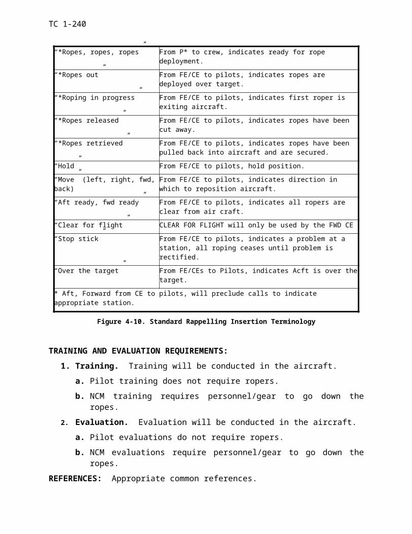
TC 1-240
(2) Simulation: Verbally describe the indications.
z. Engine HOT START.
(1) Conditions: Anytime.
(2) Simulation: Verbally state the PTIT is rising and/or smoke and flames are seen from the tail cone.
aa Residual fire during shutdown.
(1) Conditions: Anytime.
(2) Simulation: Verbally state the PTIT is rising and/or smoke and flames are seen from the tail cone.
bb Auxiliary Power Unit (APU) Fire.
(1) Conditions: During shutdown (daylight only) after a 2-minute cooldown with the ECLs in ground; or, prior to engine starting.
(2) Simulation: Verbally state the indications.
cc Engine or Fuselage Fire - Flight.
(1) Conditions: Anytime.
(2) Simulation: Place the fire detector test switch to test or verbally announce a fire: (If external load operations are being performed, the cargo hook master switch shall be OFF).
dd Engine Compartment, Fuselage, or Electrical Fire - Ground.
(1) Conditions: During shutdown after a 2-minute cooldown with the engines in ground; or during engine starting.
(2) Simulation: Place the fire detector test switch to test or verbally announce a fire. (Do not allow the crew member to place the APU or battery switch off, as you will be unable to monitor PTITs, motor the engines, or communicate with the flight engineer.)
ee Electrical Fire - Flight.
(1) Conditions: Anytime.
(2) Simulation: Verbally state a fire.
ff Smoke and Fume Elimination.
Appendix D-7
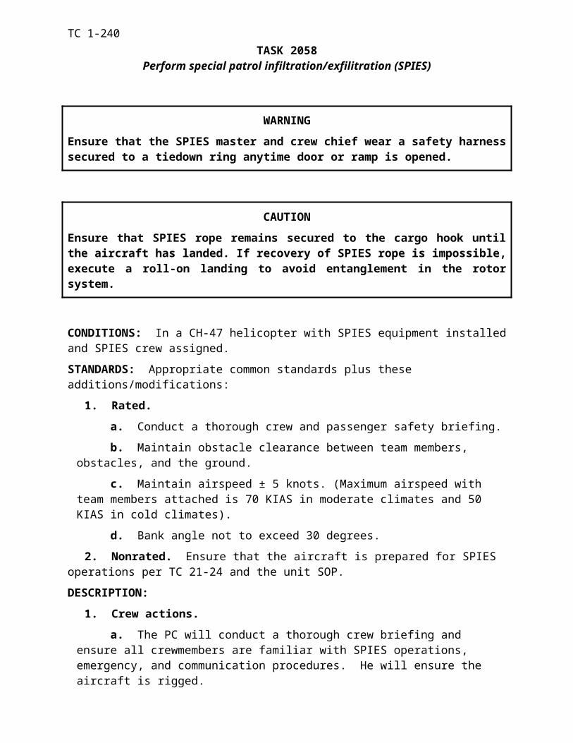
TC 1-240
(1) Conditions: During day VMC only.
(2) Simulation: State the presence of smoke and fumes in the cockpit.
gg Aux Fuel Pump Failure.
(1) Conditions: Anytime fuel is remaining in the aux tanks.
(2) Simulation: Pull the aux fuel pump DC circuit breaker (A1/A4 or C20/C21). (The crew member should detect an unbalanced fuel consumption or he should note the AUX PRESS light illuminated with fuel remaining in the tank.)
NOTE: The right AUX FUEL PUMP circuit breakers (A1 or A4) provide the power source for the left AUX PRESS light. If simulated during run-up and prior to checking the fuel pumps, an inoperative left AUX PRESS light as well as an inoperative right aux pump will normally be present.
hh Fuel Venting.
(1) Conditions: Anytime provided fuel is remaining in the aux tanks.
(2) Simulation: Verbally state the indications.
ii L or R FUEL PRESS Caution.
(1) Conditions: Anytime operating below 6,000 feet PA.
(2) Simulation: Verbally state the indications or turn both fuel pump switches for a main tank off or pull (A-2/B20) and (A-3/B21) circuit breakers.
jj Fuel Low Caution.
(1) Conditions: Anytime.(2) Simulation: Verbally state the indications.
kk FUEL LOW and FUEL PRESS Cautions.
(1) Conditions: Anytime.
(2) Simulation: Verbally state the indications.
ll No. 1 or No. 2 GEN OFF Caution.
(1) Conditions: Anytime.
(2) Simulation: Place either generator control switch to OFF.
NOTE: A bus-tie failure will only be simulated in the SFTS because of the loss of the associated AFCS, heater fan, hydraulic and avionics cooling fans, and the loss of power to vertical gyros. You may simulate the appearance of a single generator failure without a bus tie by turning off
Appendix D-8
TC 1-240
the associated generator switch, AFCS, the main fuel pump switches, and by pulling XFMR RECT AC (B22) or REV CURR (C10/D7) circuit breakers.
mm No. 1 and No. 2 GEN OFF Cautions.
(1) Conditions: Anytime.
(2) Simulation: Verbally state the indications.
nn No. 1 or No. 2 RECT OFF Caution.
(1) Conditions: Anytime.
(2) Simulation: Pull either the XFMR RECT AC circuit breaker (B22) or the REV CUR CO DC (C10/D7) circuit breaker.
NOTE: To simulate a failure of the DC bus-tie relay in flight, the AFCS and fuel boost pumps for the affected side may be turned off.
oo No. 1 and No. 2 RECT OFF Cautions.
(1) Conditions: Anytime.
(2) Simulation: Verbally state the indications.
pp BATT SYS MAL Caution.
(1) Conditions: Anytime.
(2) Simulation: Verbally state the indications.
qq No. 1 or No. 2 HYD FLT CONTR Caution.
(1) Conditions: Anytime.
(2) Simulation: Verbally state the indications.
rr No. 1 and No. 2 HYD FLT CONT Caution.
(1) Conditions: Anytime.
(2) Simulation: Verbally state the indications .
ss UTIL HYD SYS Caution.
(1) Conditions: Anytime.
(2) Simulation: Verbally state the indications.
tt Emergency Descent.
Appendix D-9
TC 1-240
(1) Conditions: Will only be performed in the CH-47FS.
(2) Simulation: Verbally state conditions requiring an emergency descent.
uu Longitudinal Cyclic Trim (LCT) System Failure.
(1) Conditions:
(a) Failure Retracted: At airspeed less than VNE for LCT retracted.
(b) Failure Extended: At cruise airspeed, not below 70 KIAS.
(1) Simulation: Place the cyclic trim switch to manual or pull the appropriate circuit breaker (B10/B9) for a failure of only one actuator. Observe airspeed operating limits.
vv Single AFCS Failure - Both Selected.
(1) Conditions: 100 KIAS or less.
(2) Simulation: Place the AFCS Selector to either No. 1 or No.2; or pull the AFCS DC circuit breaker (B13/B14). Observe airspeed operation limits.
ww Dual AFCS Failure.
(1) Conditions: 100 KIAS or less.
(2) Simulation: Place the AFCS Selector to OFF. Observe airspeed operating limits.
xx Vertical Gyro (VGI) Malfunction.
(1) Conditions: VMC, and 100 KIAS or less.
(2) Simulation: Pull the pilot's or copilots VGI circuit breaker (B16/C15).
NOTE: If altitude hold is engaged and the copilot's VGI circuit breaker is pulled, a thrust CCDA runaway will occur.
yy Differential Airspeed Hold Failure (DASH).
(1) Conditions: Anytime.
(2) Simulation: Verbally describe the indications.
zz Cockpit-Control Driver Actuator (CCDA) Failure.
(1) Conditions: Anytime except during flight in turbulence.
Appendix D-10
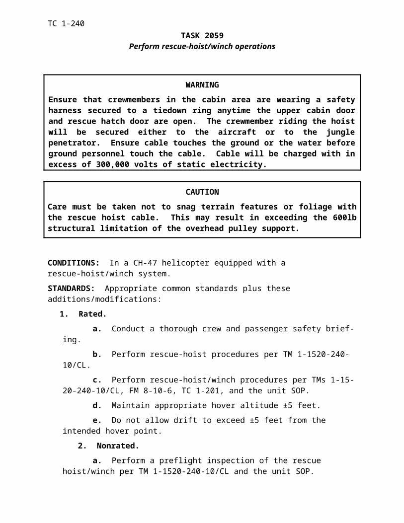
TC 1-240
(2) Simulation:
(a) Pull the CLTV DRIVER ACTR (B12) on the No. 1 PDP. (Causes altitude hold feature to become inoperative and the thrust brake to remain released).
(b) Pull the THRUST BRAKE circuit breaker (D6) on the No. 1 PDP. (Causes the thrust brake to fail locked).
Appendix D-11
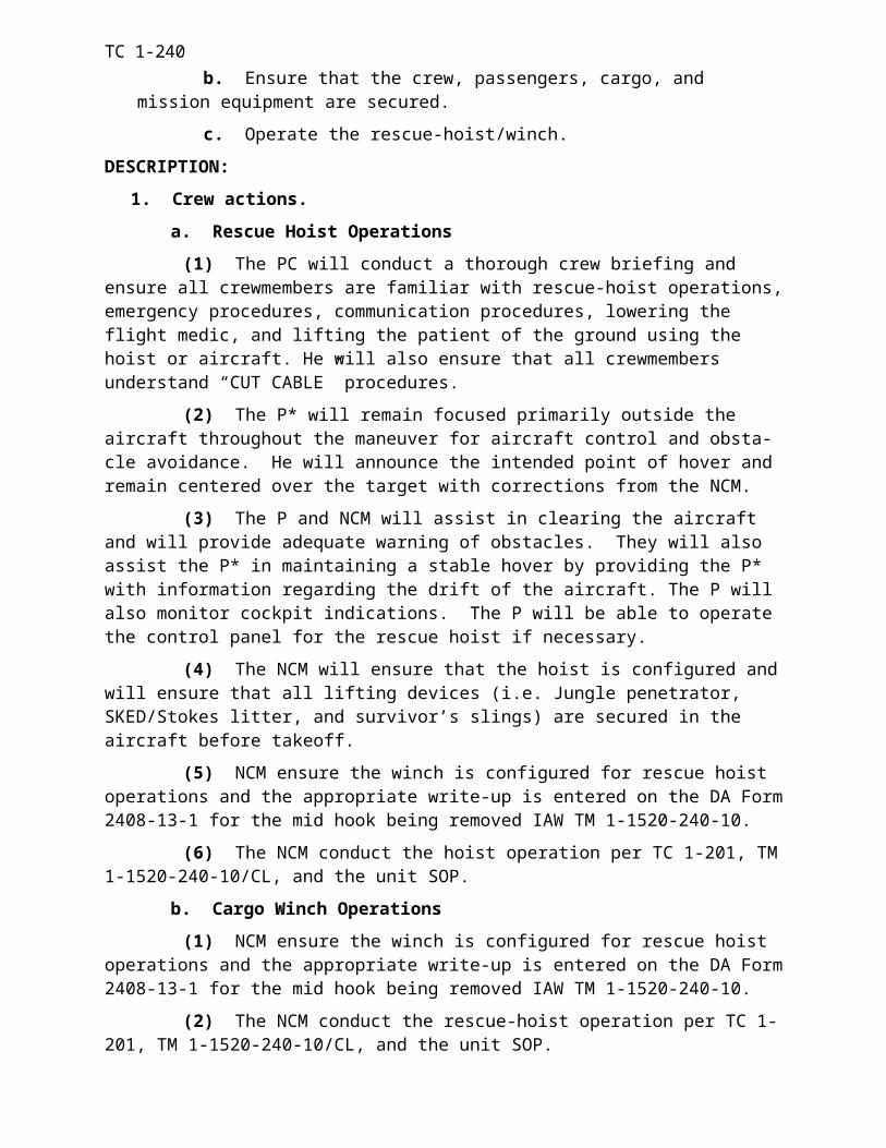
TC 1-240
ABBREVIATION TERM ABBREVIATION TERMA
Acft...............AircraftADF..............Automated Direction
FinderAFB..............Air Force BaseAFCS............Advanced Flight Control
SystemAGL.............Above Ground LevelAHO.............Above Highest ObstacleAIM..............Aeronautical
Information ManualAl..................AlabamaALSE............Aviation Life Support
EquipmentAmmo..........ammunitionANVIS..........Aviation Night Vision
Imaging SystemsAPART........Annual Proficiency and
Readiness TestAPU..............Auxiliary Power UnitAR................Army RegulationARNG..........Army National GuardASE..............Aircraft Survivability
EquipmentASR..............Airport Surveillance
RadarATC..............Air Traffic ControlATM.............Aircrew Training
ManualATP..............Aircrew Training
Programattd...............attitudeAttn..............attentionauto..............automaticAux...............auxiliaryavail..............availableAvn...............aviation
CC...................CelsiusCAB..............Combat Aviation
BrigadeCal................calibratedCav...............cavalryCDI...............Course Deviation
IndicatorCE................Crew ChiefCG................Center of GravityCH................Cargo Helicopter
CH47FS.......CH-47 Flight SimulatorCL................checklistCo.................CompanyComm..........communicationCont..............continuousCONUS........Continental United
States
DD...................day; demonstrated (for
grade slip purposes)DA................Department of the ArmyDASH...........Differential Airspeed
HoldDC................District of ColumbiaDoD..............Department of DefenseDecel.............decelerationDSN..............Defense Switching
Network
EECCM..........Electronic Counter-
CountermeasuresECL..............Engine Condition LeverEGT..............Exhaust Gas
TemperatureEmerg..........EmergencyEng...............EngineEquip............equipmentETA..............Estimated Time of
ArrivalETE..............Estimated Time En-
routeETL..............Effective Translational
LiftETP..............Exportable Training
Packet
FF....................FahrenheitFAA..............Federal Aviation
AdministrationFAC..............Flight Activity CategoryFAR..............Federal Aviation
RegulationsFARP...........Forward Arming and
Refueling PointFat................free air temperatureFE.................Flight Engineer
Glossary 1
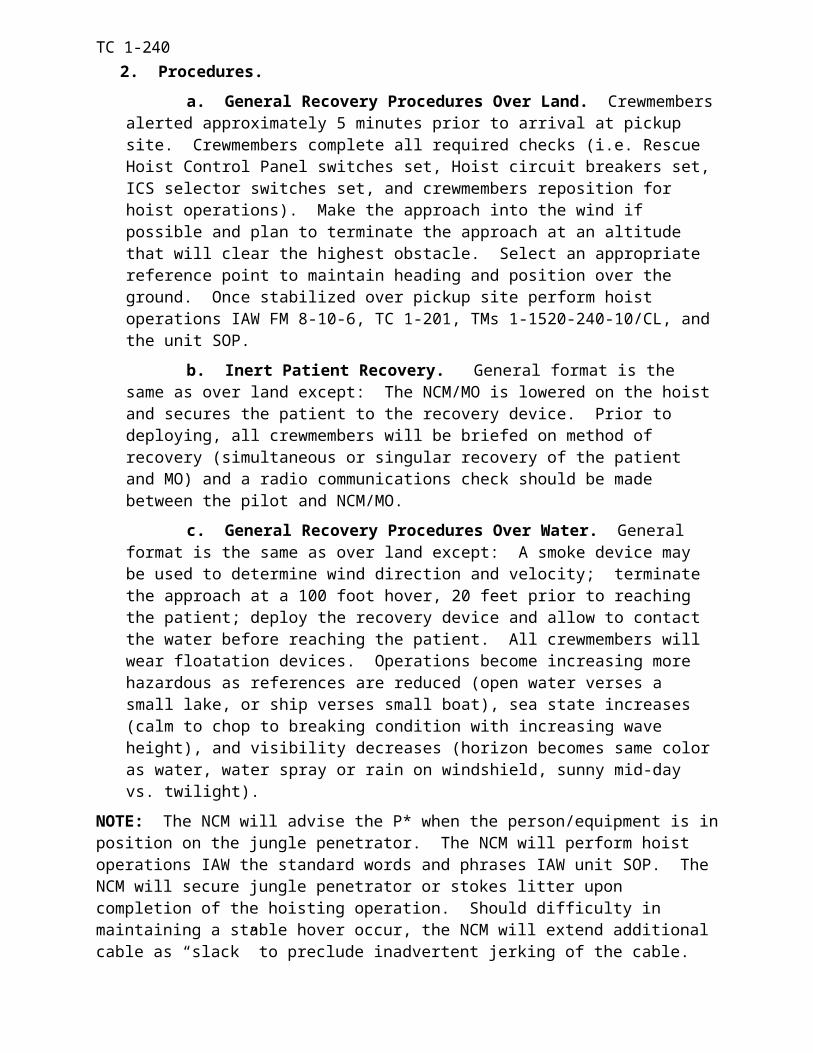
TC 1-240
ABBREVIATION TERM ABBREVIATION TERMFI..................Flight Engineer
InstructorFIH...............Flight Information
HandbookFLIP.............Flight Information
PublicationFlt.................flightFM................Field Manual or
Frequency ModulationFPM.............Feet per MinuteFW................Fixed Wing
GGA................GeorgiaGnd..............groundGr.................gradeGWT............Gross Weight
HHHT.............Headquarters and
Headquarters TroopHIT...............Health Indicator TestHQ................HeadquartersHQDA..........Headquarters,
Department of the Armyhr..................hourHSI...............Horizontal Situation
Indicator
IIAS...............Indicated AirspeedICAO............International Civil
Aviation OrganizationICS...............Inter-Communications
SystemID..................identificationIE..................Instrument Flight
ExaminerIFF................Identification, Friend or
Foe IFR...............Instrument Flight RulesIGE...............In-ground EffectILS................Instrument Landing
SystemIMC..............Instrument
Meteorological Conditions
Incl...............includedInd................indicated
IP..................Instructor Pilot
KKIAS............Knots Indicated
AirspeedKTAS...........Knots True Airspeed
LIb(s)..............pound (s)LCT..............Longitudinal Cyclic
TrimLOC.............localizerLS.................left seat
MMaint............maintenanceMAP.............Missed Approach PointMax..............maximumMD...............MarylandME................Maintenance Test Flight
EvaluatorMETL..........Mission Essential Task
ListMETT-T......Mission, Enemy,
Terrain, Troops, and Time
MG...............machine gunMIJI.............Meaconing, Intrusion,
Jamming, and Interference
Min...............minimummm...............millimeterMOPP..........Mission-Oriented
Protective PostureMP................Maintenance Test PilotMsn..............missionMTF.............Maintenance Test Flight
NN...................nightN1.................gas producer (speed)NA................not applicableNAS..............National Airspace
SystemNATO..........North Atlantic Treaty
OrganizationNav...............navigationNavaid..........navigational aid
Glossary 2
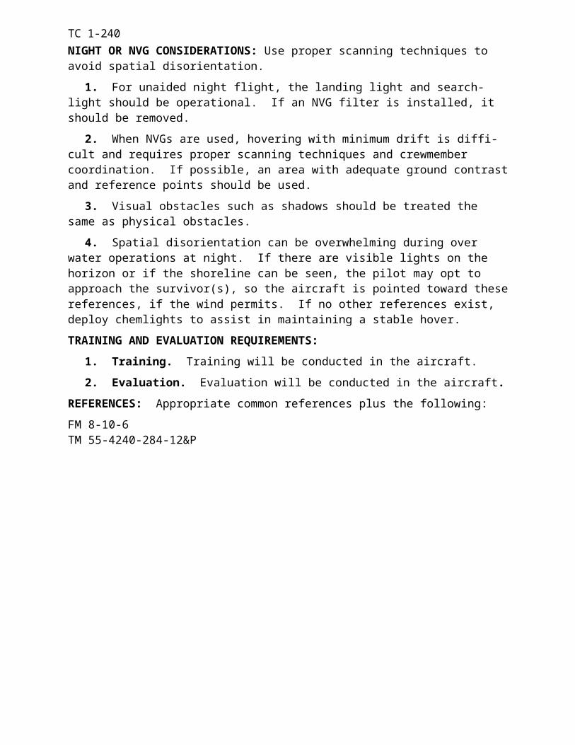
TC 1-240
ABBREVIATION TERM ABBREVIATION TERMNBC..............Nuclear, Biological,
ChemicalNCT..............Non-rated Crew
Member TrainerNCM............Non-rated Crew
MemberNDB..............Non-directional radio
beaconNGR.............National Guard
RegulationNOE.............Nap-of-the-EarthNOTAM.......Notice to AirmenNSN..............National Stock NumberNVD.............Night Vision DeviceNVG.............Night Vision GogglesNVS..............Night Vision System
OOGE.............Out-of-ground Effect
PP....................pilot not on the controlsP*..................pilot on the controlsPA.................Pressure AltitudePAC..............Power Assurance CheckPam..............pamphletPAR..............Precision Approach
RadarPax................passengerPC.................pilot in commandPI..................pilot (for grade slip
purposes)POI...............Program(s) of
InstructionPM................Preventive MaintenancePMD.............Preventive Maintenance
DailyPNVS............Pilot Night Vision
SystemPPC..............Performance Planning
CardProg..............programmedPTIT.............Power Turbine Inlet
Temperature
RR...................reproducibleR/C...............rate of climbRCM............Rated Crew Member
Recon...........reconnaissanceRet................retractRL................Readiness LevelRpm..............Revolutions per minuteRRpm...........rotor revolutions per
minuteRS.................right seatRW...............rotary wing
SS....................satisfactory (for grade
slip purposes)SALUTE......Size, Activity, Location,
Unit, Time, EquipmentSAM.............Surface-to-air MissileSel.................selectSFTS............Synthetic Flight Training
SystemsSI..................Standardization Flight
Engineer InstructorSM................Statute mileSOI...............Signal Operation
InstructionsSOP..............Standing Operating
ProcedureSP.................Standardization
Instructor PilotSSN...............Social Security NumberStanag..........Standardization
agreementStd................standardSTVA...........Self-tuning Vibration
Absorber
TTAMMS-A. .The Army Maintenance
Management System-Aviation
TAS..............True AirspeedTC................Training CircularTEAC...........Turbine Engine Analysis
CheckTM................Technical ManualTRADOC.....United States Army
Training and Doctrine Command
Glossary 3
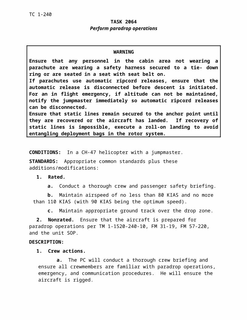
TC 1-240
ABBREVIATION TERM ABBREVIATION TERMU
U...................unsatisfactory (for grade slip purposes)
UHF..............Ultra High FrequencyUS.................United States of AmericaUSA..............United States Army
USAAVNC. .United States Army Aviation Center
USAF............United States Air ForceUT................Unit Trainer
VVa.................VirginiaVFR..............Visual Flight RulesVHF..............Very High FrequencyVMC............Visual Meteorological
ConditionsVne...............Velocity, not to exceed
(airspeed)VOR.............VHF Omni-directional
RangeVSI...............Vertical Speed Indicator
WWt.................weightWx................weather
XXmsn............transmission
ZZ...................zulu (Greenwich mean-
time)
Glossary 4
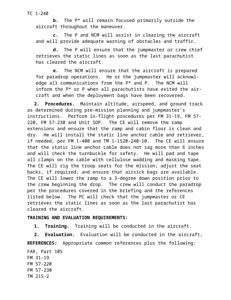
TC 1-240 REFERENCES
SOURCES USEDThese are the sources quoted or paraphrased in this publication.Army RegulationsAR 95-10. The US Military Notice to Airmen (NOTAM) System. 17 November 1990.AR 95-27. Operational Procedures for Aircraft Carrying Hazardous Materials. 9 March 1984.AR 385-95. Army Aviation Accident Prevention. 20 May 1991.Department of the Army FormDA Form 759. Individual Flight Record and Flight Certificate--Army . September 1986.Department Of Defense Airman's Information ManualDOD AIM 86-100. Operation and Maintenance Overview General Tri-service Mode 4 Handbook. May 1987.This publication is available from Commanding Officer, ATTN: Code 2111, Naval Electronic Systems Engineering Activity, St. Inigoes, MD 20684-0010, or WR-ALC/MMAM-AIMS, ATTN: DODAIMSPO, Robins AFB, GA 31098-5609.Field ManualsFM 1-101. Aviation Battlefield Survivability. 5 December 1990.FM 1-103. Airspace Management and Army Air Traffic in a Combat Zone. 30 December 1981.FM 1-104. Forward Arming and Refueling Points. 31 July 1985.FM 1-300. Flight Operations and Airfield Management. 31 October 1986.FM 1-302. Aviation Life Support Equipment (ALSE) for Army Aircrews. 30 September 1983.FM 1-500. Army Aviation Maintenance. 24 July 1989.FM 1-544. Standardized Maintenance Test Flight Procedures. 4 September 1990.FM 3-3. NBC Contamination Avoidance. 30 September 1986.FM 3-100. NBC Defense, Chemical Warfare, Smoke, and Flame Operations. 23 May 1991.FM 10-68. Aircraft Refueling. 29 May 1987.FM 17-95. Cavalry Operations. 19 September 1991.FM 20-150. National Search and Rescue Manual. 1 November 1986.FM 21-26. Map Reading and Land Navigation. 30 September 1987.FM 21-60. Visual Signals. 30 September 1987.FM 23-67. Machinegun, 7.62-mm, M60. 29 February 1984.FM 24-35. Signal Operation Instructions, “The SOI.” 26 October 1990.FM 24-35-1. Signal Supplemental Instructions. 2 October 1990.FM 25-101. Battle Focused Training. 30 September 1990.FM 34-1. Intelligence and Electronic Warfare Operations. 2 July 1987.FM 44-30. Visual Aircraft Recognition. 28 October 1986.FM 57-220. Basic Parachuting Techniques and Training. 1 June 1990.FM 100-2-3. The Soviet Army Troops Organization and Equipment. 6 June 1991.Technical ManualsTM 1-1500-328-23. Aeronautical Equipment Maintenance ManagementPolicies and Procedures. 28 February 1991.
References - 1

TC 1-240 REFERENCES
TM 9-1005-224-10. Operator/s Manual for Machine Gun, 7.62-mm, M60 W/E (NSN 1005-00-605-7710); Mount Tripod, MG, 7.62-mm, M122(1005-00-710-5599) and M60D W/E (1005-00-909-3002). 30 July 1985.TM 9-1005-262-13. Operators, Aviation Unit and Aviation Intermediate Manual for Armament Subsystem, Helicopter, 7.62-mmMachine Gun Mounts; Door Mounted, Lightweight, Model M23 . . .Lightweight, Model M24 . . . Lightweight, Model M41 . . .Lightweight, Model 144. 29 December 1986.TM 10-1670-201-23. Organizational and Direct Support MaintenanceManual for General Maintenance of Parachutes and Other Airdrop Equipment. 30 October 1973.(S) TM 11-5810-262-10. Operator’s Manual for Speech Security Equipment KY-58 (U). 1 May 1990.TM 11-5841-283-12. Aviation Unit Maintenance Manual for Radar Signal Detecting Set, AN/APR-39(V). 9 August 1983. TM 11-5855-238-10. Operator’s ManualAN/PVS-5, AN/PVS-5A, AN/PVS-5B, and TM 11-5855-263-10. Operator’s ManualVision Imaging System, AN/AVS-6(V)l 5 July 1983.TM 11-5865-201-12. Operator’s and Aviation Unit Maintenance Manual for Countermeasures Set, AN/ALQ-156(V)l. 5 March 1984.TM 55-1500-342-23. Army Aviation Maintenance Engineering Manual for Weight and Balance. 29 August 1986.TM 55-1520-240-23-1. Maintenance ManualTM 55-1520-240-23-2. Maintenance ManualTM 55-1520-240-23-3. Maintenance ManualTM 55-1520-240-23-4. Maintenance ManualTM 55-1520-240-23-5. Maintenance ManualTM 55-1520-240-23-6. Maintenance ManualTM 55-1520-240-23-7. Maintenance ManualTM 55-1520-240-23-8. Maintenance ManualTM 55-1520-240-23-9. Maintenance ManualAviation Unit and Aviation Intermediate for CH-47D Helicopters. 10 May 1983.TM 55-1520-240-23-10. Aviation Unit and Aviation intermediate Maintenance Manual: CH-47D Helicopter. 10 May 1983.TM 55-1520-240-T-1. Aviation Unit and Aviation Intermediate Troubleshooting Manual for CH-47D Helicopter. 10 May 1983.TM 55-1520-240-T-2. Aviation Unit and Aviation Intermediate Troubleshooting Manual for CH-47D Helicopter. 10 May 1983.TM 55-1520-240-T-3. Aviation Unit and Aviation Intermediate Troubleshooting Manual for CH-47D Helicopter. 10 May 1983.DOCUMENTS NEEDEDThese documents must be available to the intended users of thispublication.Army Regulations*AR 40-8. Temporary Flying Restrictions Due to Exogenous Factors. 17 August 1976.*AR 95-1. Aviation: Flight Regulations. 30 May 1990.*AR 95-2. Aviation: Air Traffic Control, Airspace, Airfields, Flight Activities, and Navigational Aids. 10 August 1990.
References - 2
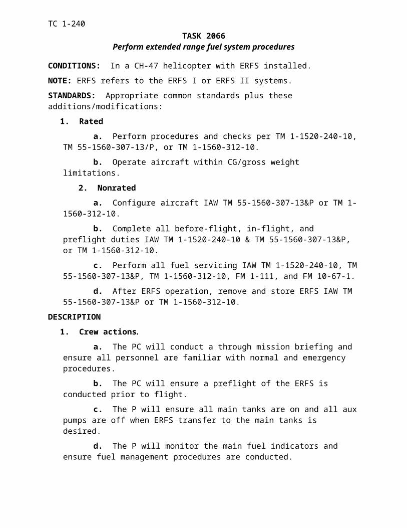
TC 1-240 REFERENCES
*AR 190-11. Physical Security of Arms, Ammunition and Explosives. 31 March 1986.*AR 190-51. Security of Army Property at Unit and Installation Level. 31 March 1986.*AR 600-105. Aviation Service of Rated Army Officers. 15 Dec 1994.*AR 600-106. Flying Status for Nonrated Army Aviation Personnel. 8 Dec 1998.Department of the Army FormsDA Form 2028. Recommended Changes to Publications and Blank Forms. February 1974.DA Form 2404. Equipment Inspection and Maintenance Worksheet. April 1979.DA Form 2408-12. Army Aviator’s Flight Record. January 1964.DA Form 2408-13. Aircraft Inspection and Maintenance Record. December 1966.DA Form 4887-R. RW Performance Planning Card. August 2004.DA Form 5484-R. Aircrew Mission Briefing. September 1997.*This source was also used to develop this publication.References-4*DA Pam 738-751. Functional Users Manual for the Army Maintenance Management System-Aviation (TAMMS-A). 15 January 1988.Department of Defense Flight Information PublicationFlight Information HandbookThe DOD FLIP is available from Director, US Army Aeronautical Services Agency, ATTN: MOAS-AI, Cameron Station, Alexandria, VA. 22304-5050.Department of Defense FormsDD Form 175. Military Flight Plan. May 1986.DD Form 365-4. Weight and Balance Clearance Form F. April 1989.Federal Aviation Administration PublicationsAirman’s Information ManualFAR Part 91. General Operating and Flight Rules.These publications are available from Director, US Army Aeronautical Services Agency, ATTN: MOAS-AI, Cameron Station, Alexandria, VA 22304-5050.Field Manuals*FM 1-107. Air-to-Air Combat.*FM 1-112. Tactics, Techniques, and Procedures for the AttackHelicopter Battalion. 21 February 1991.*FM 1-116. Tactics, Techniques, and Procedures for the Air Cavalry/Reconnaissance Troop. 20 February 1991.*FM 1-202. Environmental Flight. 23 February 1983.*FM 1-203. Fundamentals of Flight. 3 October 1988.*FM 1-230. Meteorology for Army Aviators. 30 September 1982.*FM 1-240. Instrument Flying and Navigation for Army Aviators.15 December 1984.*FM 3.04-301. Aeromedical Training for Flight Personnel. 29 September 2000.*FM 1-400. Aviator’s Handbook. 31 May 1983.*FM 1-402. Aviator’s Recognition Manual. 6 August 1984.*FM 55-450-20 Army Helicopter Internal Load Operations. 24 August 1984.*FM 10-450-3. Multiservice Helicopter External Air Transport: Basic Operations and Equipment. 10 April 1997.*FM 10-450-4 Multiservice Helicopter Single-Point Rigging Procedures. 30 May 1998
References - 3
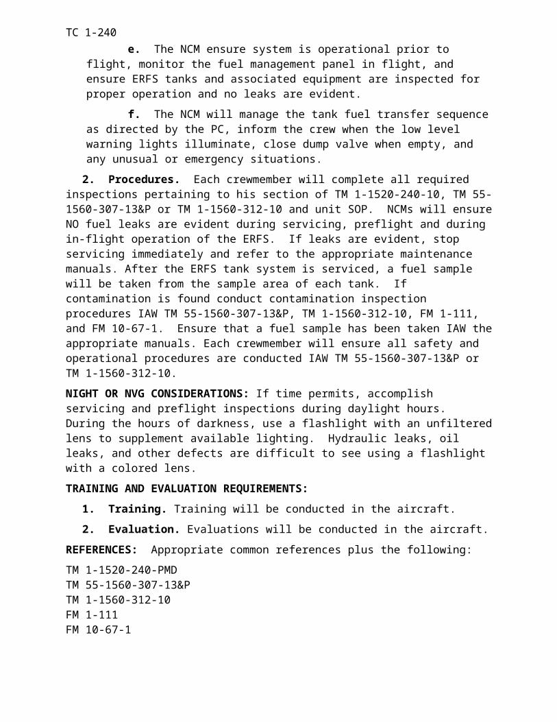
TC 1-240 REFERENCES
*FM 55-450-5. Multiservice Helicopter Dual Point Load Rigging Procedures. 30 August 1999.National Guard Regulation*NGR 95-2100 Army National Guard: General Provisions and Regulations for Aviation Training. 1 October 1990.Training Circulars*FM 3-04.140. Helicopter Gunnery. 14 July 2003.*TC 1-201. Tactical Flight Procedures. 20 January 1984.*TC 1-204. Night Flight Techniques and Procedures. 27 December 1988.*TC 1-210. Aircrew Training Program, Commander’s Guide to Individual and Crew Training. 20 May 1992.Technical Manuals*TM 11-5895-1199-12. Operator’s and Organizational Maintenance for Mark-XII IFF System (AN/APX-100; AN/APX-72). 1 July 1984.*TM 10-1520-240-10. Operator’s Manual” for Army CH-47D Helicopter.10 November 1982.*TM 55-1520-240-CL. Operator's and Crewmember's Checklist for Army Model CH-47D Helicopter. 1 0 N o v e m b e r 1 9 8 2.*TM 55-1520-240-MTF. Maintenance Test Flight Manual for Army’Model CH-47D Helicopter. 8 September 1982.*TM 55-1520-240-PM. CH-47D Helicopter, Phased MaintenanceChecklist. 18 October 1990.*TM 55-1520-240-PMD. CH-47D Helicopter Preventive MaintenanceDaily Inspection Checklist. 6 September 1988.*TM 55-2840-248-230 Aviation Unit and Intermediate Maintenance Manual for Engine, Aircraft, Turboshaft, Model T700-GE-700 and T700-GE-701. 28 April 1982.READING RECOMMENDEDThis reading contains relevant supplemental information.FM 25-100. Training the Force. 15 November 1988.
References - 4
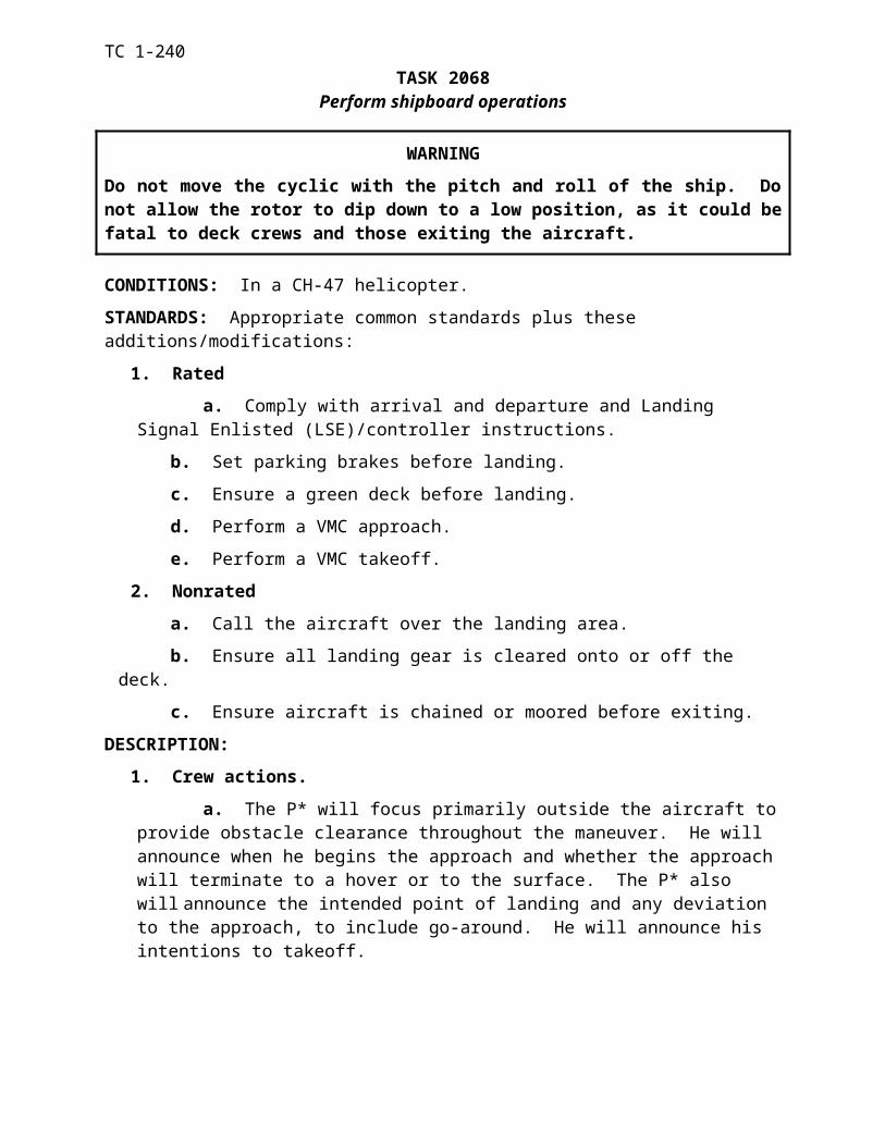
TC 1-240
CH-47 PERFORMANCE PLANNING CARDFor use of this form, see TC 1-240: The proponent agency is TRADOC
DEPARTURE DATAOPERATING WT: FUEL WT: LOAD: TAKEOFF GWT: /
PRESSURE ALT: FAT:
FUEL MANAGEMENT: QTY________TIME___________ PPH ____________ BURNOUT__________ RSV _________
DUAL ENGINE SINGLE ENGINE
NO LOAD WITH LOAD NO LOAD WITH LOAD
MAX TQ AVAIL – 10 MIN / S/E TQ
MAX TORQUE AVAIL. – 30 MINUTE
CONTINUOUS TORQUE AVAIL.
PREDICTED HVR TQ – IGE / OGE / /
//
GO / NO-GO TQ
MAX ALLOW. GWT – IGE / OGE / /
VALIDATION FACTOR CRUISE DATA
CGI INOP Vne: / LCT RET Vne: / DRAG FACTOR:
PRESSURE ALT: FAT: NO LOAD WITH LOAD NO LOAD WITH LOAD
MAX TQ AVAIL – 10 MIN / S/E TQ
CONTINUOUS TORQUE AVAIL.
MAX R/C AND ENDURANCE IAS
MAX RANGE IAS
CRUISE SPEED – IAS
CRUISE TORQUE (+ DRAG FACTOR)
CRUISE FUEL FLOW
MINIMUM SINGLE ENGINE IAS
MAXIMUM SINGLE ENGINE IAS
MAX GWT S/E / SESC /ARRIVAL DATA
LANDING GWT: / DUAL ENGINE SINGLE ENGINE
PRESSURE ALT: FAT: NO LOAD WITH LOAD NO LOAD WITH LOAD
MAX TQ AVAIL - 10 MIN / S/E TQ
MAX TORQUE AVAIL. – 30 MINUTE
PREDICTED HVR TQ – IGE / OGE / / / /
MAX ALLOW. GWT – IGE / OGE / /DA FORM 4887-47