Embed Size (px)
Citation preview

User Manual TBI 0310
Page 1 of 26
USER MANUAL
TBI 0310 6/2012
TRAUMATIC BRAIN INJURY
DEVICE
User Manual TBI 0310
Page 2 of 26
Setting up the TBI 0310 Head Impactor The TBI 0310 Head Impactor when fully assembled has the following components:
1. Control box 2. Impactor head stage assembly 3. Base plate for stereotaxic frame with stand post 4. Jun-Air compressed air pump 5. Flexible air hose with couplers (1) 6. Contact sensor 7. Calibration block 8. Rat impactor tip (5.0mm) 9. Mouse impactor tip (3.0mm) 10. Connection wire for contact sensor 11. AC power cord for control box 12. Quick release air coupler – female (1) 13. Hex wrench (set) 14. Spare impactor tip set screws (5)
The TBI 0310 stand has been disassembled for shipping. Assembly is fairly simple. However it may require 2 people due to the weight of the components. The bolts are socket head cap screws fitting a 3/16” hex wrench, included. For ease of assembly start all bolts before tightening any. Screw them in nearly all the way but leave them slightly loose. Refer to the photographs of the finished assembly for guidance.
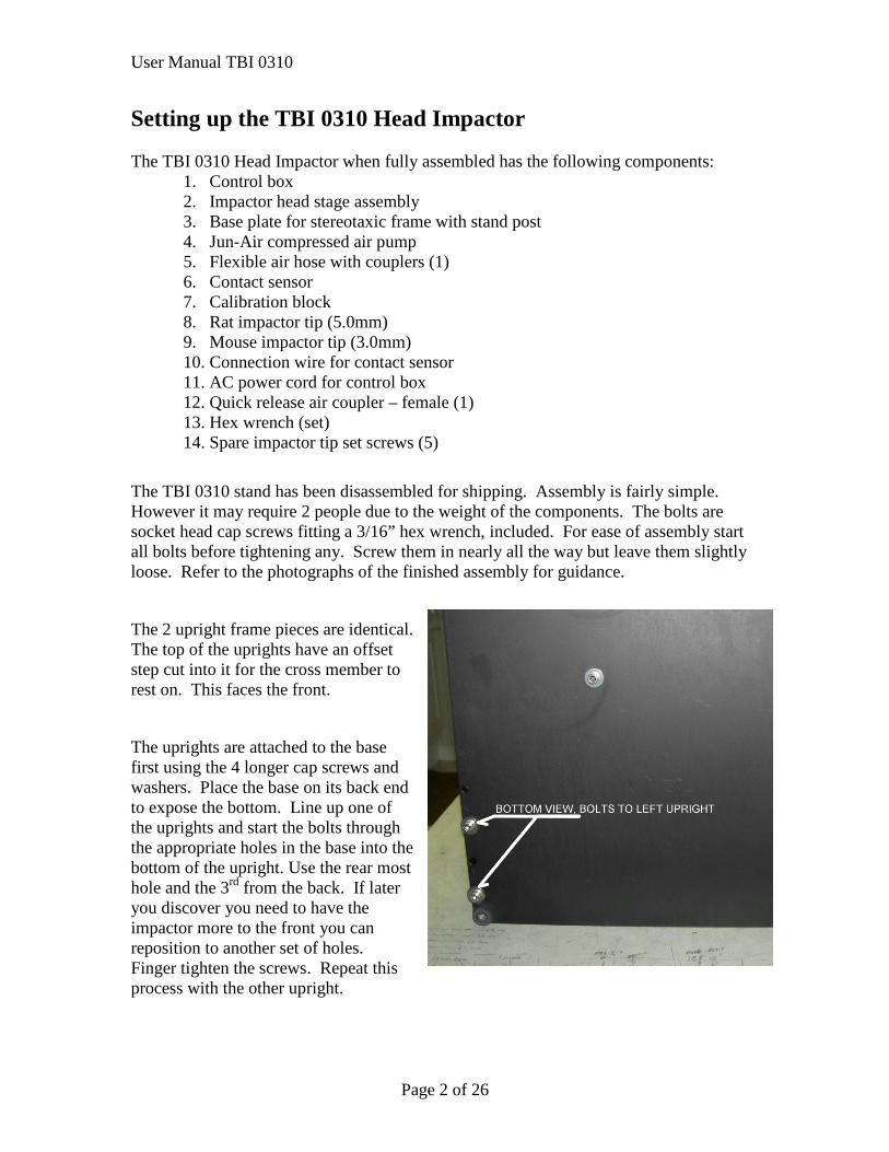
The 2 upright frame pieces are identical. The top of the uprights have an offset step cut into it for the cross member to rest on. This faces the front.
The uprights are attached to the base first using the 4 longer cap screws and washers. Place the base on its back end to expose the bottom. Line up one of the uprights and start the bolts through the appropriate holes in the base into the bottom of the upright. Use the rear most hole and the 3rd from the back. If later you discover you need to have the impactor more to the front you can reposition to another set of holes. Finger tighten the screws. Repeat this process with the other upright.
User Manual TBI 0310
Page 3 of 26
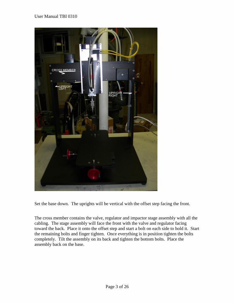
Set the base down. The uprights will be vertical with the offset step facing the front.
The cross member contains the valve, regulator and impactor stage assembly with all the cabling. The stage assembly will face the front with the valve and regulator facing toward the back. Place it onto the offset step and start a bolt on each side to hold it. Start the remaining bolts and finger tighten. Once everything is in position tighten the bolts completely. Tilt the assembly on its back and tighten the bottom bolts. Place the assembly back on the base.
User Manual TBI 0310
Page 4 of 26
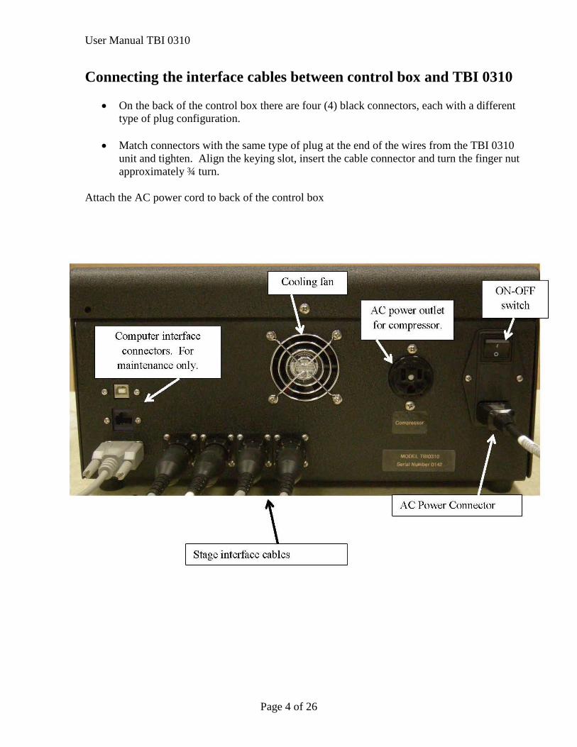
Connecting the interface cables between control box and TBI 0310
• On the back of the control box there are four (4) black connectors, each with a different type of plug configuration.
• Match connectors with the same type of plug at the end of the wires from the TBI 0310
unit and tighten. Align the keying slot, insert the cable connector and turn the finger nut approximately ¾ turn.
Attach the AC power cord to back of the control box
User Manual TBI 0310
Page 5 of 26
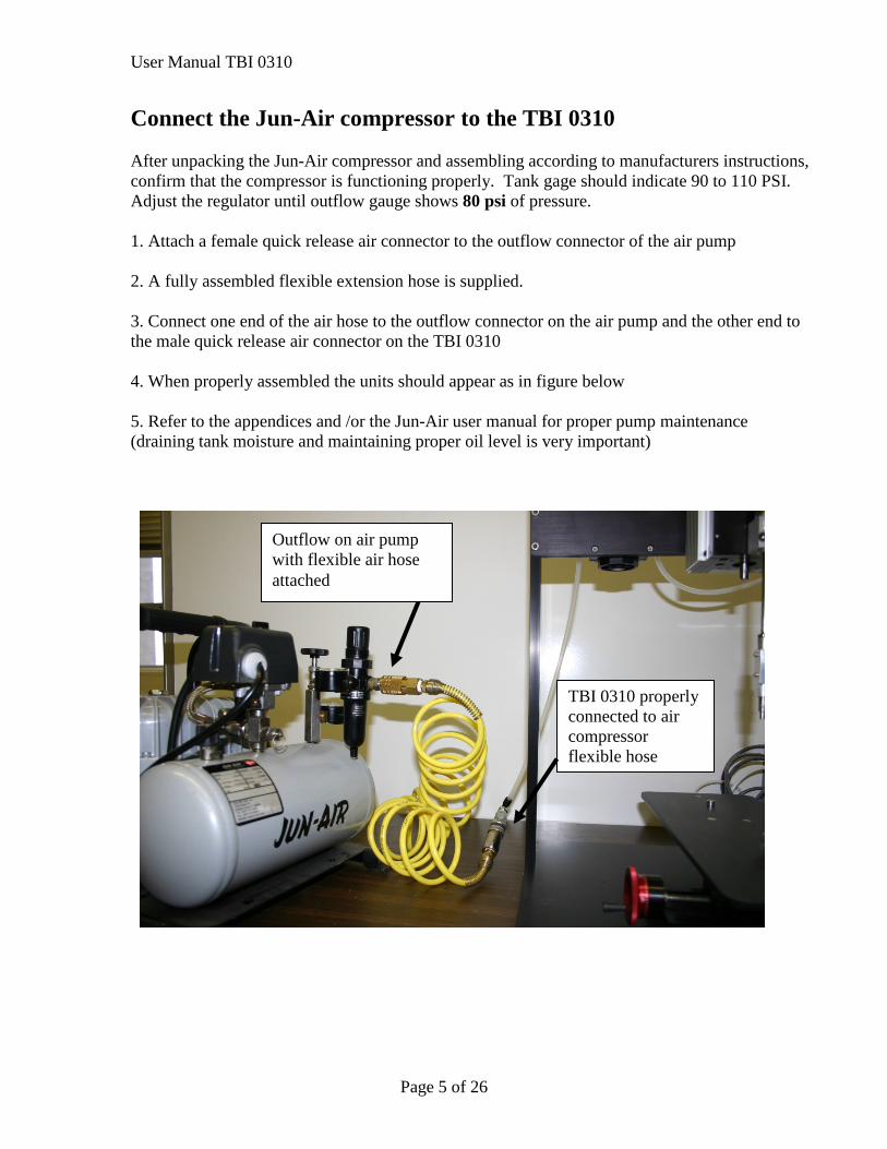
Connect the Jun-Air compressor to the TBI 0310 After unpacking the Jun-Air compressor and assembling according to manufacturers instructions, confirm that the compressor is functioning properly. Tank gage should indicate 90 to 110 PSI. Adjust the regulator until outflow gauge shows 80 psi of pressure. 1. Attach a female quick release air connector to the outflow connector of the air pump 2. A fully assembled flexible extension hose is supplied. 3. Connect one end of the air hose to the outflow connector on the air pump and the other end to the male quick release air connector on the TBI 0310 4. When properly assembled the units should appear as in figure below 5. Refer to the appendices and /or the Jun-Air user manual for proper pump maintenance (draining tank moisture and maintaining proper oil level is very important)
Outflow on air pump with flexible air hose attached
TBI 0310 properly connected to air compressor flexible hose
User Manual TBI 0310
Page 6 of 26
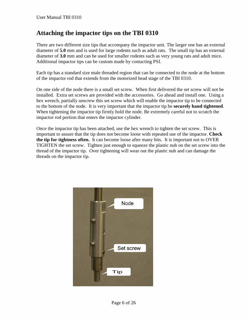
Attaching the impactor tips on the TBI 0310 There are two different size tips that accompany the impactor unit. The larger one has an external diameter of 5.0 mm and is used for large rodents such as adult rats. The small tip has an external diameter of 3.0 mm and can be used for smaller rodents such as very young rats and adult mice. Additional impactor tips can be custom made by contacting PSI. Each tip has a standard size male threaded region that can be connected to the node at the bottom of the impactor rod that extends from the motorized head stage of the TBI 0310. On one side of the node there is a small set screw. When first delivered the set screw will not be installed. Extra set screws are provided with the accessories. Go ahead and install one. Using a hex wrench, partially unscrew this set screw which will enable the impactor tip to be connected to the bottom of the node. It is very important that the impactor tip be securely hand tightened. When tightening the impactor tip firmly hold the node. Be extremely careful not to scratch the impactor rod portion that enters the impactor cylinder. Once the impactor tip has been attached, use the hex wrench to tighten the set screw. This is important to assure that the tip does not become loose with repeated use of the impactor. Check the tip for tightness often. It can become loose after many hits. It is important not to OVER TIGHTEN the set screw. Tighten just enough to squeeze the plastic nub on the set screw into the thread of the impactor tip. Over tightening will wear out the plastic nub and can damage the threads on the impactor tip.
User Manual TBI 0310
Page 7 of 26
Calibrating the CONTACT SENSOR • Prior to using the TBI Head Impactor for the first experiment it is extremely important to
calibrate the CONTACT SENSOR • This procedure informs the control unit what the distance is between the bottom of the
impactor tip and the bottom of the CONTACT SENSOR • This information is extremely important in order that the correct cortical deformation is
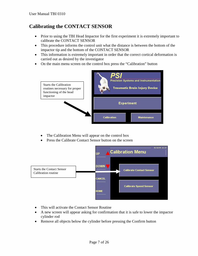
carried out as desired by the investigator • On the main menu screen on the control box press the “Calibration” button
• The Calibration Menu will appear on the control box • Press the Calibrate Contact Sensor button on the screen
• This will activate the Contact Sensor Routine • A new screen will appear asking for confirmation that it is safe to lower the impactor
cylinder rod • Remove all objects below the cylinder before pressing the Confirm button
Starts the Calibration routines necessary for proper functioning of the head impactor
Starts the Contact Sensor Calibration routine
User Manual TBI 0310
Page 8 of 26
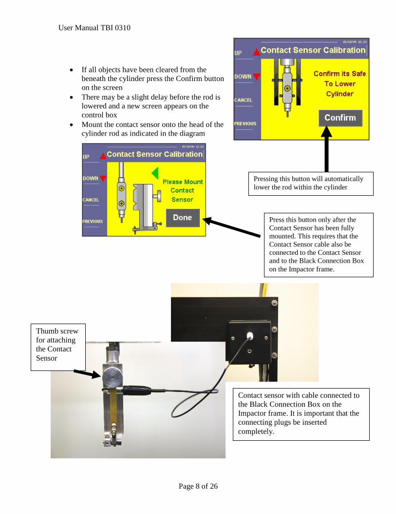
• If all objects have been cleared from the beneath the cylinder press the Confirm button on the screen
• There may be a slight delay before the rod is lowered and a new screen appears on the control box
• Mount the contact sensor onto the head of the cylinder rod as indicated in the diagram
Pressing this button will automatically lower the rod within the cylinder
Press this button only after the Contact Sensor has been fully mounted. This requires that the Contact Sensor cable also be connected to the Contact Sensor and to the Black Connection Box on the Impactor frame.
Contact sensor with cable connected to the Black Connection Box on the Impactor frame. It is important that the connecting plugs be inserted completely.
Thumb screw for attaching the Contact Sensor
User Manual TBI 0310
Page 9 of 26
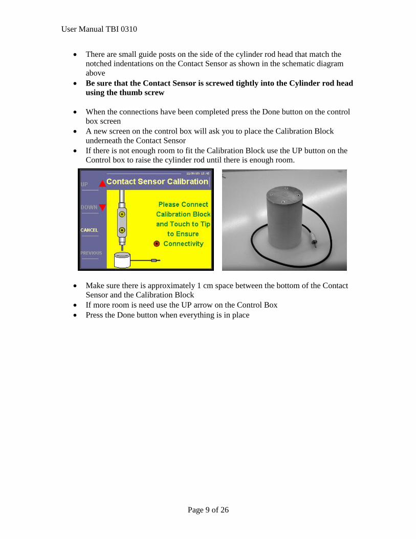
• There are small guide posts on the side of the cylinder rod head that match the notched indentations on the Contact Sensor as shown in the schematic diagram above
• Be sure that the Contact Sensor is screwed tightly into the Cylinder rod head using the thumb screw
• When the connections have been completed press the Done button on the control
box screen • A new screen on the control box will ask you to place the Calibration Block
underneath the Contact Sensor • If there is not enough room to fit the Calibration Block use the UP button on the
Control box to raise the cylinder rod until there is enough room.
• Make sure there is approximately 1 cm space between the bottom of the Contact
Sensor and the Calibration Block • If more room is need use the UP arrow on the Control Box • Press the Done button when everything is in place
User Manual TBI 0310
Page 10 of 26
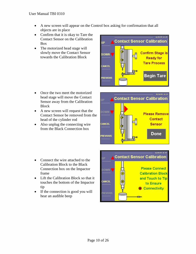
• A new screen will appear on the Control box asking for confirmation that all objects are in place
• Confirm that it is okay to Tare the Contact Sensor on the Calibration Box
• The motorized head stage will slowly move the Contact Sensor towards the Calibration Block
• Once the two meet the motorized
head stage will move the Contact Sensor away from the Calibration Block
• A new screen will request that the Contact Sensor be removed from the head of the cylinder rod
• Also unplug the connecting wire from the Black Connection box
• Connect the wire attached to the Calibration Block to the Black Connection box on the Impactor frame
• Lift the Calibration Block so that it touches the bottom of the Impactor tip
• If the connection is good you will hear an audible beep
User Manual TBI 0310
Page 11 of 26
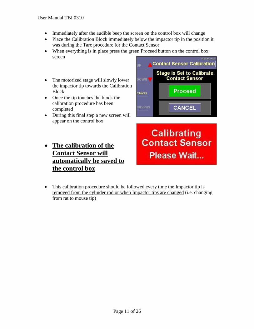
• Immediately after the audible beep the screen on the control box will change • Place the Calibration Block immediately below the impactor tip in the position it
was during the Tare procedure for the Contact Sensor • When everything is in place press the green Proceed button on the control box
screen
• The motorized stage will slowly lower the impactor tip towards the Calibration Block
• Once the tip touches the block the calibration procedure has been completed
• During this final step a new screen will appear on the control box
• The calibration of the Contact Sensor will automatically be saved to the control box
• This calibration procedure should be followed every time the Impactor tip is
removed from the cylinder rod or when Impactor tips are changed (i.e. changing from rat to mouse tip)
User Manual TBI 0310
Page 12 of 26
Calibrating the SPEED SENSOR
• This procedure is necessary prior to the first time use of the instrument • It is NOT necessary to calibrate the Speed Sensor before each experiment or
when the tip is changed • This calibration procedure should
only be carried out if the instrument has not been used for an extended period of time (3 months) or if maintenance that affects the position of the sensors has been preformed.
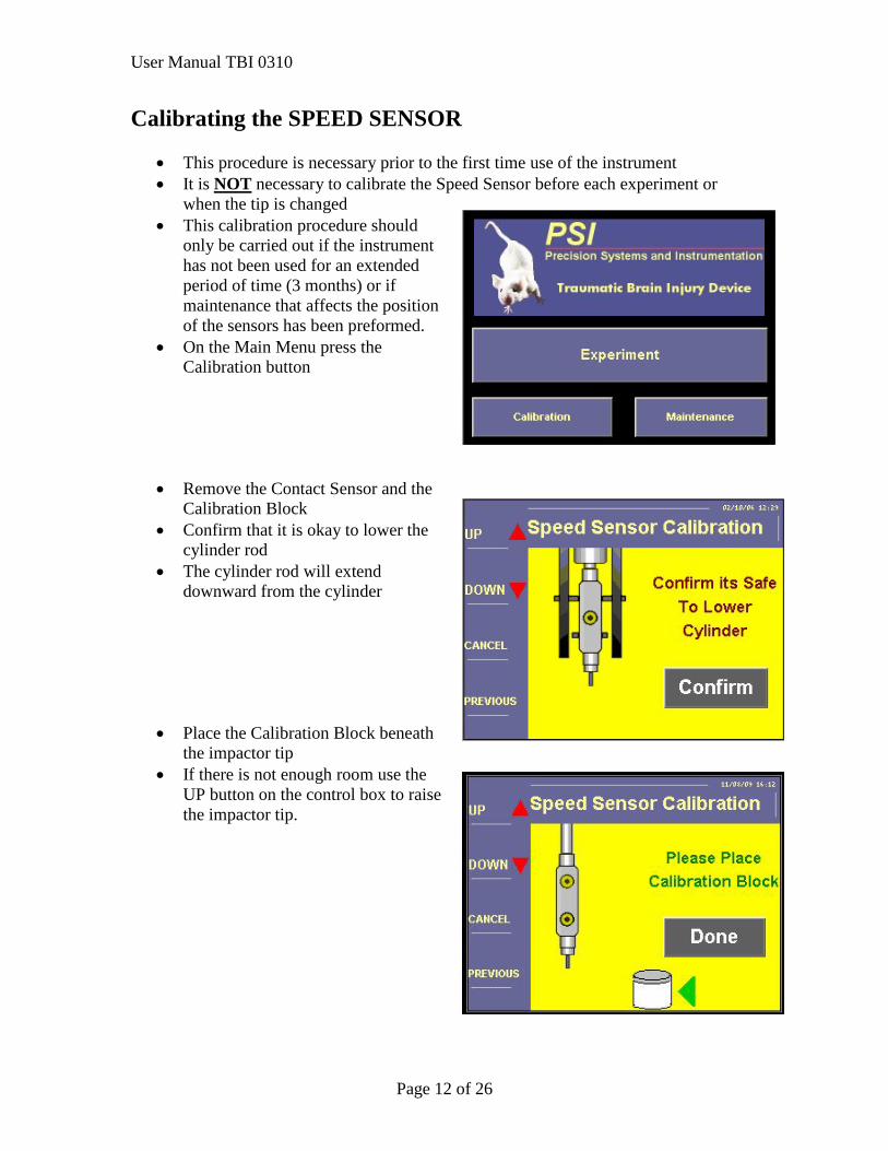
• On the Main Menu press the Calibration button
• Remove the Contact Sensor and the Calibration Block
• Confirm that it is okay to lower the cylinder rod
• The cylinder rod will extend downward from the cylinder
• Place the Calibration Block beneath
the impactor tip • If there is not enough room use the
UP button on the control box to raise the impactor tip.
User Manual TBI 0310
Page 13 of 26
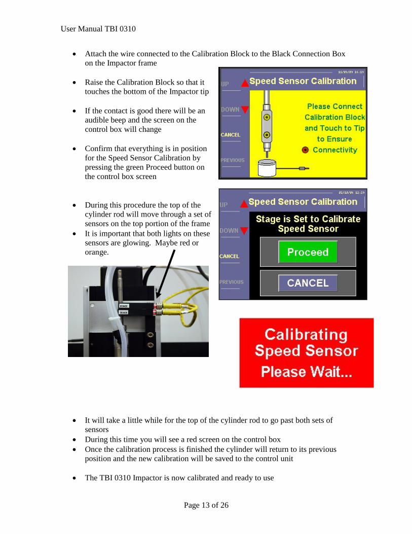
• Attach the wire connected to the Calibration Block to the Black Connection Box on the Impactor frame
• Raise the Calibration Block so that it
touches the bottom of the Impactor tip
• If the contact is good there will be an audible beep and the screen on the control box will change
• Confirm that everything is in position
for the Speed Sensor Calibration by pressing the green Proceed button on the control box screen
• During this procedure the top of the cylinder rod will move through a set of sensors on the top portion of the frame
• It is important that both lights on these sensors are glowing. Maybe red or orange.
• It will take a little while for the top of the cylinder rod to go past both sets of sensors
• During this time you will see a red screen on the control box • Once the calibration process is finished the cylinder will return to its previous
position and the new calibration will be saved to the control unit
• The TBI 0310 Impactor is now calibrated and ready to use
User Manual TBI 0310
Page 14 of 26
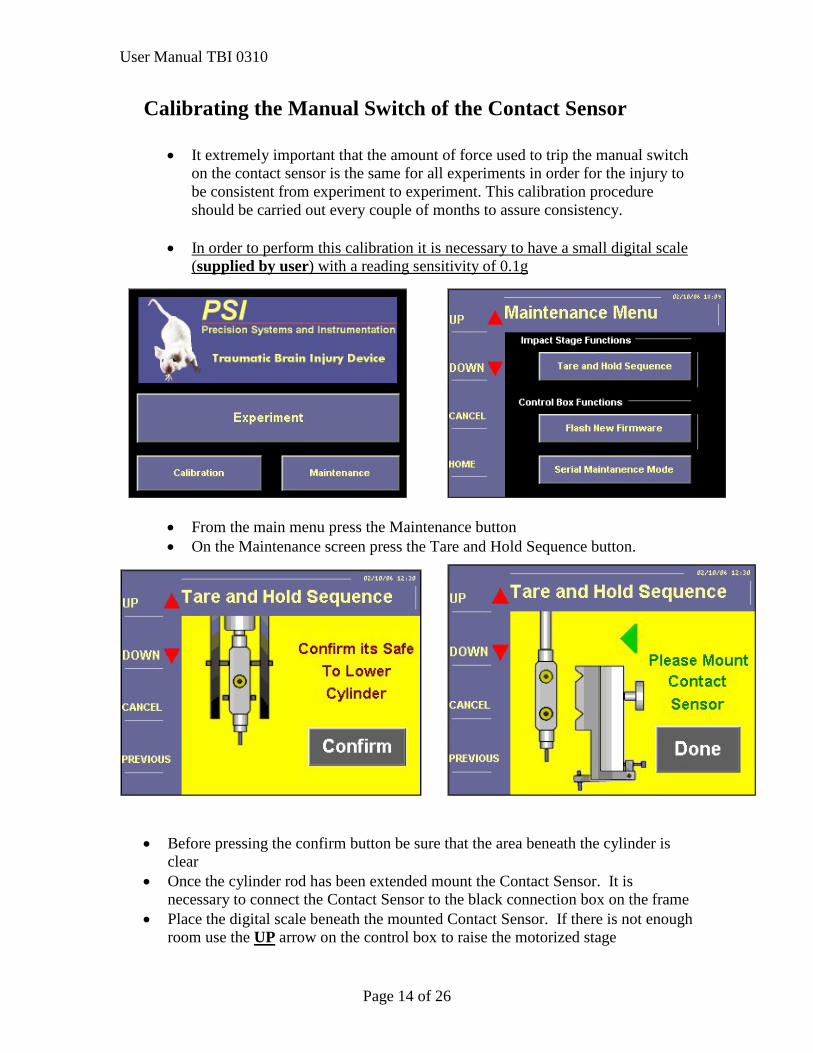
Calibrating the Manual Switch of the Contact Sensor
• It extremely important that the amount of force used to trip the manual switch on the contact sensor is the same for all experiments in order for the injury to be consistent from experiment to experiment. This calibration procedure should be carried out every couple of months to assure consistency.
• In order to perform this calibration it is necessary to have a small digital scale
(supplied by user) with a reading sensitivity of 0.1g
• From the main menu press the Maintenance button • On the Maintenance screen press the Tare and Hold Sequence button.
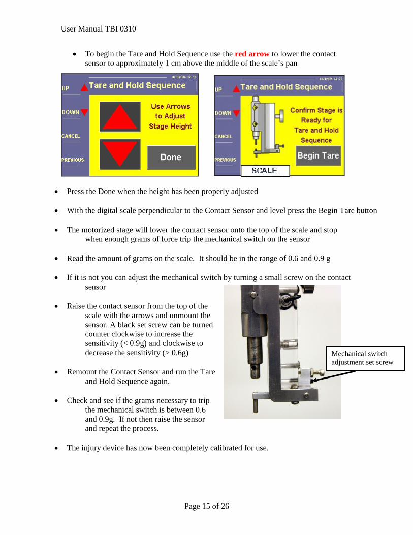
• Before pressing the confirm button be sure that the area beneath the cylinder is clear
• Once the cylinder rod has been extended mount the Contact Sensor. It is necessary to connect the Contact Sensor to the black connection box on the frame
• Place the digital scale beneath the mounted Contact Sensor. If there is not enough room use the UP arrow on the control box to raise the motorized stage
User Manual TBI 0310
Page 15 of 26
• To begin the Tare and Hold Sequence use the red arrow to lower the contact sensor to approximately 1 cm above the middle of the scale’s pan
• Press the Done when the height has been properly adjusted
• With the digital scale perpendicular to the Contact Sensor and level press the Begin Tare button
• The motorized stage will lower the contact sensor onto the top of the scale and stop
when enough grams of force trip the mechanical switch on the sensor
• Read the amount of grams on the scale. It should be in the range of 0.6 and 0.9 g
• If it is not you can adjust the mechanical switch by turning a small screw on the contact sensor
• Raise the contact sensor from the top of the
scale with the arrows and unmount the sensor. A black set screw can be turned counter clockwise to increase the sensitivity (< 0.9g) and clockwise to decrease the sensitivity (> 0.6g)
• Remount the Contact Sensor and run the Tare
and Hold Sequence again.
• Check and see if the grams necessary to trip the mechanical switch is between 0.6 and 0.9g. If not then raise the sensor and repeat the process.
• The injury device has now been completely calibrated for use.
Mechanical switch adjustment set screw
User Manual TBI 0310
Page 16 of 26
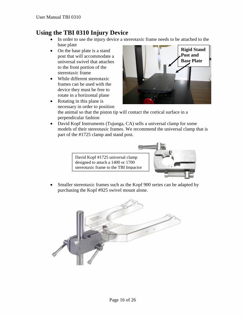
Using the TBI 0310 Injury Device • In order to use the injury device a stereotaxic frame needs to be attached to the
base plate • On the base plate is a stand
post that will accommodate a universal swivel that attaches to the front portion of the stereotaxic frame
• While different stereotaxic frames can be used with the device they must be free to rotate in a horizontal plane
• Rotating in this plane is necessary in order to position the animal so that the piston tip will contact the cortical surface in a perpendicular fashion
• David Kopf Instruments (Tujunga, CA) sells a universal clamp for some models of their stereotaxic frames. We recommend the universal clamp that is part of the #1725 clamp and stand post.
• Smaller stereotaxic frames such as the Kopf 900 series can be adapted by purchasing the Kopf #925 swivel mount alone.
Rigid Stand Post and Base Plate
David Kopf #1725 universal clamp designed to attach a 1400 or 1700 stereotaxic frame to the TBI Impactor
User Manual TBI 0310
Page 17 of 26
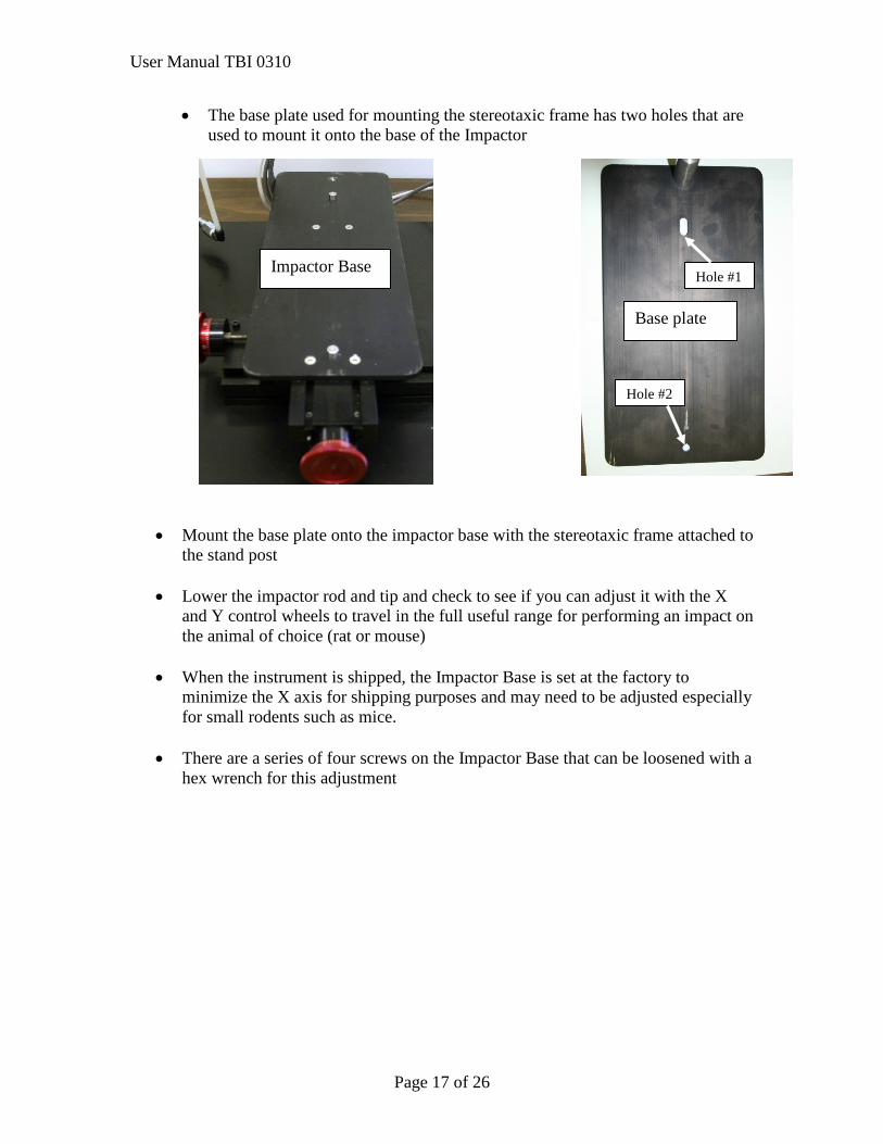
• The base plate used for mounting the stereotaxic frame has two holes that are used to mount it onto the base of the Impactor
• Mount the base plate onto the impactor base with the stereotaxic frame attached to the stand post
• Lower the impactor rod and tip and check to see if you can adjust it with the X
and Y control wheels to travel in the full useful range for performing an impact on the animal of choice (rat or mouse)
• When the instrument is shipped, the Impactor Base is set at the factory to
minimize the X axis for shipping purposes and may need to be adjusted especially for small rodents such as mice.
• There are a series of four screws on the Impactor Base that can be loosened with a
hex wrench for this adjustment
Base plate
Hole #1
Hole #2
Impactor Base
User Manual TBI 0310
Page 18 of 26
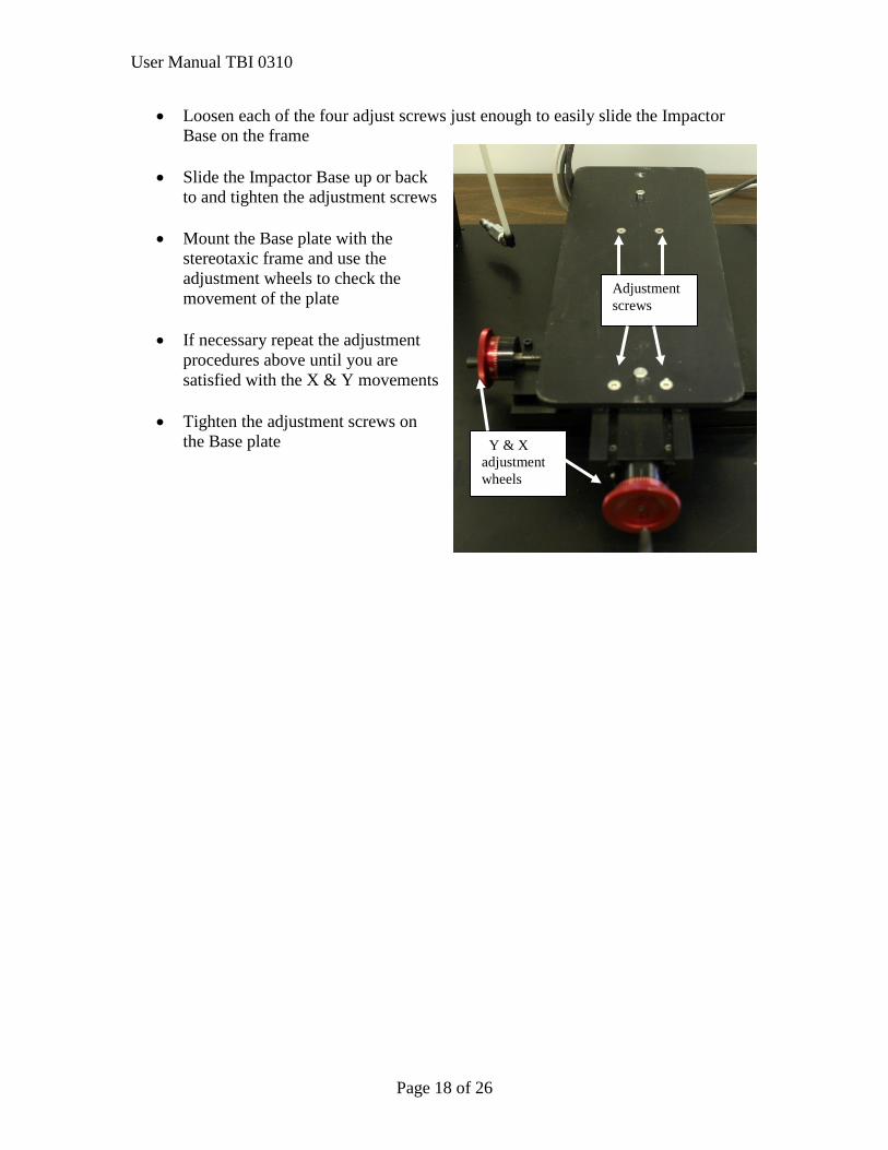
• Loosen each of the four adjust screws just enough to easily slide the Impactor Base on the frame
• Slide the Impactor Base up or back
to and tighten the adjustment screws
• Mount the Base plate with the stereotaxic frame and use the adjustment wheels to check the movement of the plate
• If necessary repeat the adjustment
procedures above until you are satisfied with the X & Y movements
• Tighten the adjustment screws on
the Base plate
Adjustment screws
Y & X adjustment wheels
User Manual TBI 0310
Page 19 of 26
Performing an impact with TBI 0310
• Place the animal in the stereotaxic frame on the base of the impactor and be sure that the holes in the base plate line up with the holes on the base of the impactor
• It is important that that base plate fit flat on the impactor base. To assist in the
mounting of the base plate one of the holes has an oblong shape.
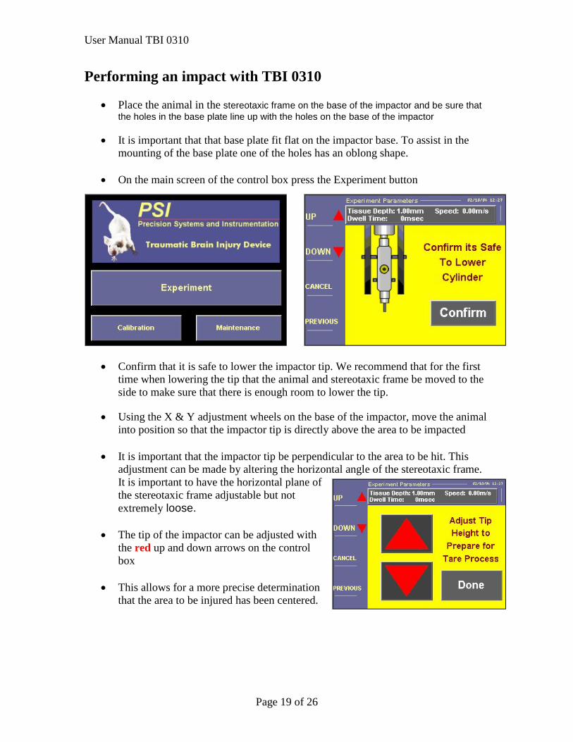
• On the main screen of the control box press the Experiment button
• Confirm that it is safe to lower the impactor tip. We recommend that for the first
time when lowering the tip that the animal and stereotaxic frame be moved to the side to make sure that there is enough room to lower the tip.
• Using the X & Y adjustment wheels on the base of the impactor, move the animal
into position so that the impactor tip is directly above the area to be impacted
• It is important that the impactor tip be perpendicular to the area to be hit. This adjustment can be made by altering the horizontal angle of the stereotaxic frame. It is important to have the horizontal plane of the stereotaxic frame adjustable but not extremely loose.
• The tip of the impactor can be adjusted with
the red up and down arrows on the control box
• This allows for a more precise determination
that the area to be injured has been centered.
User Manual TBI 0310
Page 20 of 26
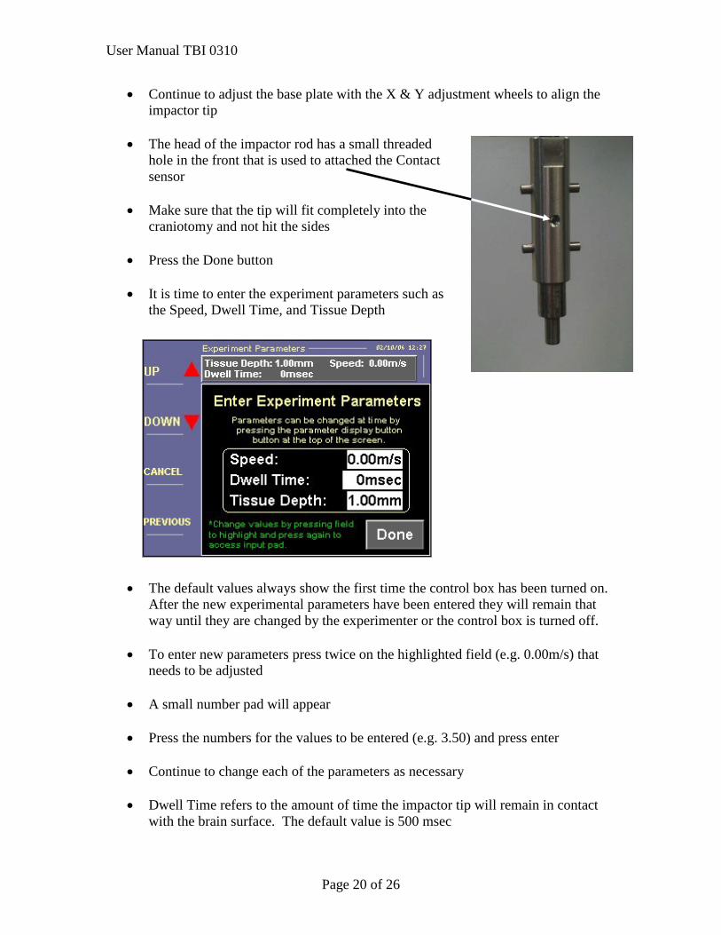
• Continue to adjust the base plate with the X & Y adjustment wheels to align the impactor tip
• The head of the impactor rod has a small threaded
hole in the front that is used to attached the Contact sensor
• Make sure that the tip will fit completely into the
craniotomy and not hit the sides
• Press the Done button
• It is time to enter the experiment parameters such as the Speed, Dwell Time, and Tissue Depth
• The default values always show the first time the control box has been turned on. After the new experimental parameters have been entered they will remain that way until they are changed by the experimenter or the control box is turned off.
• To enter new parameters press twice on the highlighted field (e.g. 0.00m/s) that
needs to be adjusted
• A small number pad will appear
• Press the numbers for the values to be entered (e.g. 3.50) and press enter
• Continue to change each of the parameters as necessary
• Dwell Time refers to the amount of time the impactor tip will remain in contact with the brain surface. The default value is 500 msec
User Manual TBI 0310
Page 21 of 26
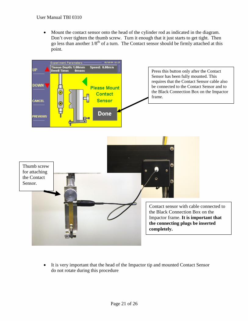
• Mount the contact sensor onto the head of the cylinder rod as indicated in the diagram. Don’t over tighten the thumb screw. Turn it enough that it just starts to get tight. Then go less than another 1/8th of a turn. The Contact sensor should be firmly attached at this point.
• It is very important that the head of the Impactor tip and mounted Contact Sensor do not rotate during this procedure
Contact sensor with cable connected to the Black Connection Box on the Impactor frame. It is important that the connecting plugs be inserted completely.
Thumb screw for attaching the Contact Sensor.
Press this button only after the Contact Sensor has been fully mounted. This requires that the Contact Sensor cable also be connected to the Contact Sensor and to the Black Connection Box on the Impactor frame.
User Manual TBI 0310
Page 22 of 26
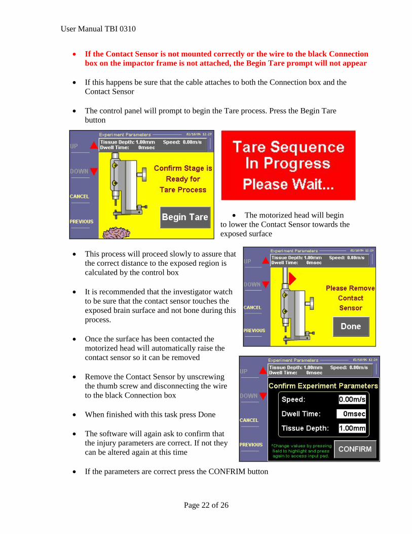
• If the Contact Sensor is not mounted correctly or the wire to the black Connection box on the impactor frame is not attached, the Begin Tare prompt will not appear
• If this happens be sure that the cable attaches to both the Connection box and the
Contact Sensor
• The control panel will prompt to begin the Tare process. Press the Begin Tare button
• The motorized head will begin
to lower the Contact Sensor towards the exposed surface
• This process will proceed slowly to assure that
the correct distance to the exposed region is calculated by the control box
• It is recommended that the investigator watch
to be sure that the contact sensor touches the exposed brain surface and not bone during this process.
• Once the surface has been contacted the
motorized head will automatically raise the contact sensor so it can be removed
• Remove the Contact Sensor by unscrewing
the thumb screw and disconnecting the wire to the black Connection box
• When finished with this task press Done
• The software will again ask to confirm that
the injury parameters are correct. If not they can be altered again at this time
• If the parameters are correct press the CONFRIM button
User Manual TBI 0310
Page 23 of 26
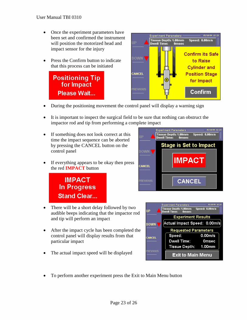
• Once the experiment parameters have been set and confirmed the instrument will position the motorized head and impact sensor for the injury
• Press the Confirm button to indicate
that this process can be initiated
• During the positioning movement the control panel will display a warning sign
• It is important to inspect the surgical field to be sure that nothing can obstruct the impactor rod and tip from performing a complete impact
• If something does not look correct at this
time the impact sequence can be aborted by pressing the CANCEL button on the control panel
• If everything appears to be okay then press
the red IMPACT button
• There will be a short delay followed by two audible beeps indicating that the impactor rod and tip will perform an impact
• After the impact cycle has been completed the
control panel will display results from that particular impact
• The actual impact speed will be displayed
• To perform another experiment press the Exit to Main Menu button
User Manual TBI 0310
Page 24 of 26
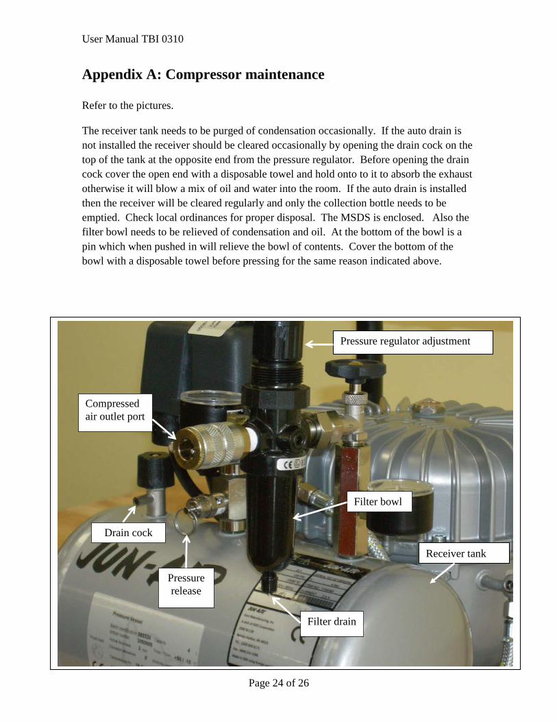
Appendix A: Compressor maintenance Refer to the pictures. The receiver tank needs to be purged of condensation occasionally. If the auto drain is not installed the receiver should be cleared occasionally by opening the drain cock on the top of the tank at the opposite end from the pressure regulator. Before opening the drain cock cover the open end with a disposable towel and hold onto to it to absorb the exhaust otherwise it will blow a mix of oil and water into the room. If the auto drain is installed then the receiver will be cleared regularly and only the collection bottle needs to be emptied. Check local ordinances for proper disposal. The MSDS is enclosed. Also the filter bowl needs to be relieved of condensation and oil. At the bottom of the bowl is a pin which when pushed in will relieve the bowl of contents. Cover the bottom of the bowl with a disposable towel before pressing for the same reason indicated above.
Pressure regulator adjustment
Filter bowl
Filter drain
Pressure release
Drain cock
Compressed air outlet port
Receiver tank
User Manual TBI 0310
Page 25 of 26
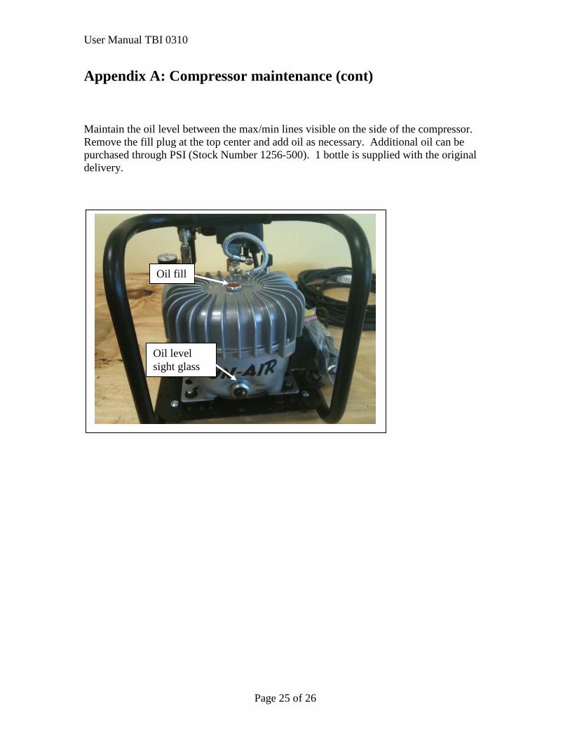
Appendix A: Compressor maintenance (cont) Maintain the oil level between the max/min lines visible on the side of the compressor. Remove the fill plug at the top center and add oil as necessary. Additional oil can be purchased through PSI (Stock Number 1256-500). 1 bottle is supplied with the original delivery.
Oil fill
Oil level sight glass
User Manual TBI 0310
Page 26 of 26
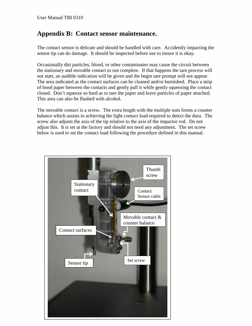
Appendix B: Contact sensor maintenance. The contact sensor is delicate and should be handled with care. Accidently impacting the sensor tip can do damage. It should be inspected before use to insure it is okay. Occasionally dirt particles, blood, or other contaminates may cause the circuit between the stationary and movable contact to not complete. If that happens the tare process will not start, an audible indication will be given and the begin tare prompt will not appear. The area indicated as the contact surfaces can be cleaned and/or burnished. Place a strip of bond paper between the contacts and gently pull it while gently squeezing the contact closed. Don’t squeeze so hard as to tare the paper and leave particles of paper attached. This area can also be flushed with alcohol. The movable contact is a screw. The extra length with the multiple nuts forms a counter balance which assists in achieving the light contact load required to detect the dura. The screw also adjusts the axis of the tip relative to the axis of the impactor rod. Do not adjust this. It is set at the factory and should not need any adjustment. The set screw below is used to set the contact load following the procedure defined in this manual.
Sensor tip
Movable contact & counter balance
Stationary contact Contact
Sensor cable
Set screw
Thumb screw
Contact surfaces