Embed Size (px)
Citation preview
TAC System Guidelines 1
INTRODUCTION
During recent years an increasing amount of attention has been paid to air distributionsystems that individually condition the immediate environments of office workers withintheir workstations. As with task/ambient lighting systems, the controls for the “task”components of these systems are partially or entirely decentralized and under the controlof the occupants. Typically, the occupant has control over the speed and direction, and insome cases the temperature, of the incoming air supply. Variously called “task/ambientconditioning,” “localized thermal distribution,” and “personalized air conditioning” systems,these systems have been most commonly installed in open-plan office buildings in whichthey provide supply air and (in some cases) radiant heating directly into workstations. Alarge majority of these systems have included a raised access floor system through whichunderfloor air distribution is used to deliver conditioned air to the space through floor grills,or in conjunction with the workstation furniture and partitions.
The purpose of this document is to present and discuss engineering and applicationguidelines and recommendations that encourage the intelligent design, installation, andoperation of task/ambient conditioning (TAC) systems in commercial buildings. A well-designed TAC system should take maximum advantage of the potential improvements inthermal comfort, ventilation performance, indoor air quality, and occupant satisfaction andproductivity, while minimizing energy use and costs. The development of these guidelinesis based on a compilation of available information, including (1) TAC system designexperience described in the literature, (2) laboratory experiments on several TAC systems,(3) field studies of TAC systems installed and operated in buildings, (4) computersimulations of whole-building energy use with and without TAC systems, (5) a survey ofheating, ventilating, and air-conditioning (HVAC) engineers and manufacturers about TACsystems, and (6) the results of the Workshop on Task/Ambient Conditioning Systems inCommercial Buildings, May 4-5, 1995, held in San Francisco, California [Bauman 1995].Since experience with TAC systems is still rather limited, the recommendations andguidelines contained in this guide represent our best estimates at this time of soundengineering judgment. As more information and experience becomes available, weexpect to periodically revise and improve this document. The guide is intended for use bydesign engineers, architects, building owners, facility managers, equipment manufacturersand installers, utility engineers, researchers, and other users of TAC technology.
Definition and System Overview
A task/ambient conditioning (TAC) system is defined as any space conditioning systemthat allows thermal conditions in small, localized zones (e.g., regularly occupied worklocations) to be individually controlled by building occupants, while still automaticallymaintaining acceptable environmental conditions in the ambient space of the building(e.g., corridors, open-use space, and other areas outside of regularly occupied workspace). TAC systems are generally configured as air distribution systems that have arelatively large number of supply locations within the building, many in close proximity tothe building occupants, as compared to a conventional ceiling-based air distributionsystem. TAC systems are uniquely characterized by their ability to allow individuals tohave some amount of control over their local environment, without adversely affecting thatof other nearby occupants. Depending on the TAC system design, ambient environmental
2 TAC System Guidelines
control may be provided by additional local supply outlets, or by a separate spaceconditioning system, but in either case under central or automatic control. Although not arequirement, the design of a majority of TAC systems has involved the use of underfloorair distribution in which supply air from a conventional air handling plant is delivered to theplenum under a raised access floor where it is allowed to flow freely through the plenum tothe supply locations. Other configurations are possible, as will be discussed later in thisguide.
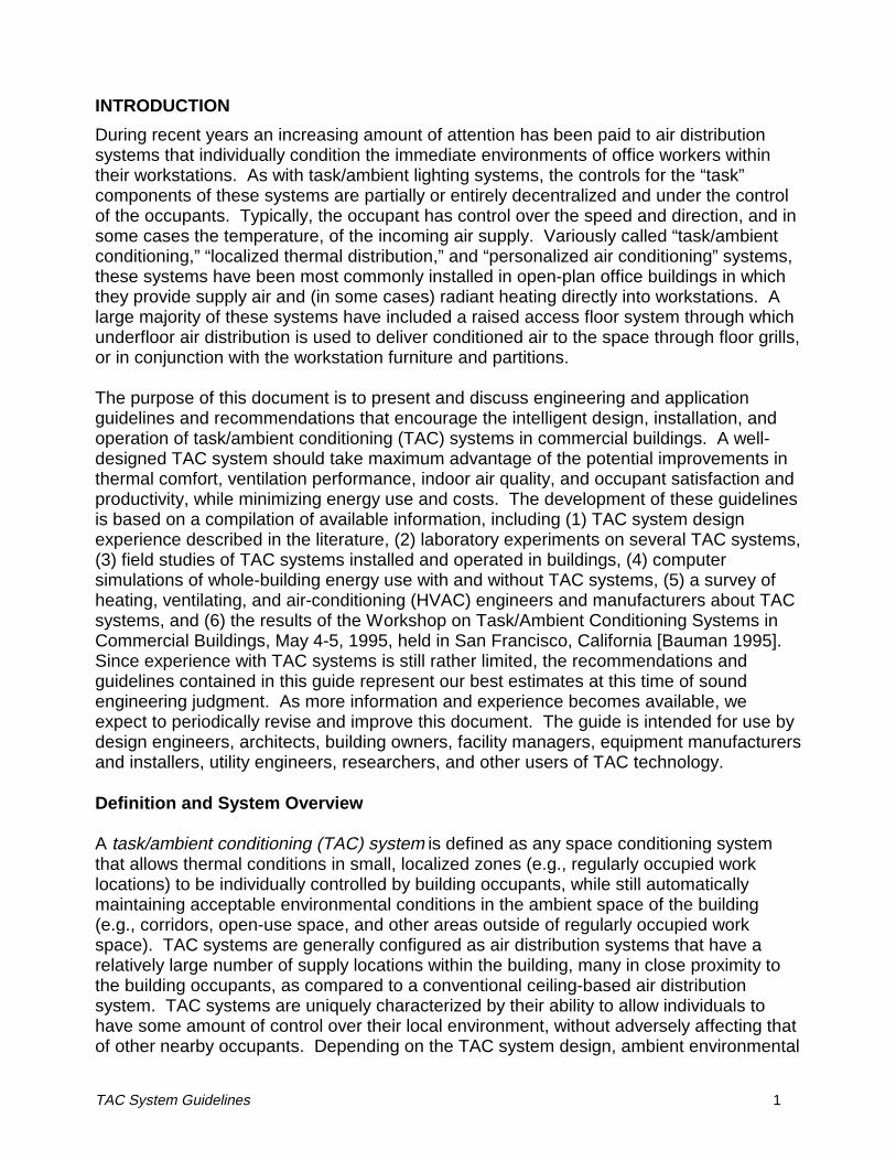
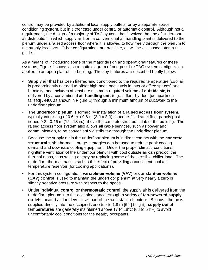
As a means of introducing some of the major design and operational features of thesesystems, Figure 1 shows a schematic diagram of one possible TAC system configurationapplied to an open plan office building. The key features are described briefly below.
• Supply air that has been filtered and conditioned to the required temperature (cool airis predominantly needed to offset high heat load levels in interior office spaces) andhumidity, and includes at least the minimum required volume of outside air, isdelivered by a conventional air handling unit (e.g., a floor-by-floor [compartmen-talized] AHU, as shown in Figure 1) through a minimum amount of ductwork to theunderfloor plenum.
• The underfloor plenum is formed by installation of a raised access floor system,typically consisting of 0.6 m x 0.6 m (2 ft x 2 ft) concrete-filled steel floor panels posi-tioned 0.3 - 0.46 m (12 - 18 in.) above the concrete structural slab of the building. Theraised access floor system also allows all cable services, such as power andcommunication, to be conveniently distributed through the underfloor plenum.
• Because the supply air in the underfloor plenum is in direct contact with the concretestructural slab, thermal storage strategies can be used to reduce peak coolingdemand and downsize cooling equipment. Under the proper climatic conditions,nighttime ventilation of the underfloor plenum with cool outside air can precool thethermal mass, thus saving energy by replacing some of the sensible chiller load. Theunderfloor thermal mass also has the effect of providing a consistent cool airtemperature reservoir (for cooling applications).
• For this system configuration, variable-air-volume (VAV) or constant-air-volume(CAV) control is used to maintain the underfloor plenum at very nearly a zero orslightly negative pressure with respect to the space.
• Under individual control or thermostatic control, the supply air is delivered from theunderfloor plenum into the occupied space through a variety of fan-powered supplyoutlets located at floor level or as part of the workstation furniture. Because the air issupplied directly into the occupied zone (up to 1.8 m [6 ft] height), supply outlettemperatures are generally maintained above 17 to 18°C (63 to 64°F) to avoiduncomfortably cool conditions for the nearby occupants.
TAC System Guidelines 3
Figure 1. Schematic diagram of task/ambient conditioning system with low-pressureunderfloor plenum
A.B.C.1.2.3.4.5.6.7.8.
Perimeter zoneInterior zone with high occupancyInterior zone with low occupancyAir handling unitOutside airSupply air to underfloor plenumUnderfloor plenumStructural slabFan-powered terminal box with reheatFloor diffuser (ducted)Occupant-controlled fan-powered floordiffuser
9.
10.
11.
12.13.14.15.16.
Fan-powered floor unit con-nected to air flow partitionOccupant-controlled partition-based diffusersThermostatically controlledfan-powered floor diffuserReturn air through lightsCeiling plenumInduction shaft for return airReturn airExhaust air
• Individual office workers can control their local thermal environment over a relativelywide range (typically by adjusting the volume and trajectory of the supply air enteringthe space), giving them the opportunity to fine-tune the thermal conditions in theirworkstation to their personal comfort preferences. Different supply outlet configu-rations may be used depending on the conditioning requirements for a particular zoneof the building, as discussed below.
• The additional heating and cooling loads of perimeter zones can be handled by in-stalling fan-powered terminal (VAV) boxes with reheat (electric or hot water) in theunderfloor plenum. Under thermostatic control these VAV boxes deliver plenum airwith or without reheat directly to floor diffusers through flexible ductwork to enablequick response on calls for heating (e.g., morning warm-up).
4 TAC System Guidelines
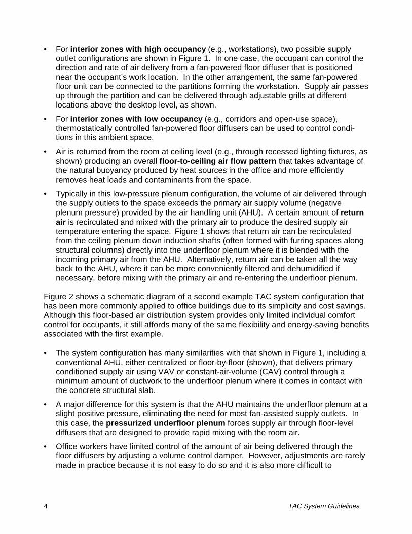
• For interior zones with high occupancy (e.g., workstations), two possible supplyoutlet configurations are shown in Figure 1. In one case, the occupant can control thedirection and rate of air delivery from a fan-powered floor diffuser that is positionednear the occupant’s work location. In the other arrangement, the same fan-poweredfloor unit can be connected to the partitions forming the workstation. Supply air passesup through the partition and can be delivered through adjustable grills at differentlocations above the desktop level, as shown.
• For interior zones with low occupancy (e.g., corridors and open-use space),thermostatically controlled fan-powered floor diffusers can be used to control condi-tions in this ambient space.
• Air is returned from the room at ceiling level (e.g., through recessed lighting fixtures, asshown) producing an overall floor-to-ceiling air flow pattern that takes advantage ofthe natural buoyancy produced by heat sources in the office and more efficientlyremoves heat loads and contaminants from the space.
• Typically in this low-pressure plenum configuration, the volume of air delivered throughthe supply outlets to the space exceeds the primary air supply volume (negativeplenum pressure) provided by the air handling unit (AHU). A certain amount of returnair is recirculated and mixed with the primary air to produce the desired supply airtemperature entering the space. Figure 1 shows that return air can be recirculatedfrom the ceiling plenum down induction shafts (often formed with furring spaces alongstructural columns) directly into the underfloor plenum where it is blended with theincoming primary air from the AHU. Alternatively, return air can be taken all the wayback to the AHU, where it can be more conveniently filtered and dehumidified ifnecessary, before mixing with the primary air and re-entering the underfloor plenum.
Figure 2 shows a schematic diagram of a second example TAC system configuration thathas been more commonly applied to office buildings due to its simplicity and cost savings.Although this floor-based air distribution system provides only limited individual comfortcontrol for occupants, it still affords many of the same flexibility and energy-saving benefitsassociated with the first example.
• The system configuration has many similarities with that shown in Figure 1, including aconventional AHU, either centralized or floor-by-floor (shown), that delivers primaryconditioned supply air using VAV or constant-air-volume (CAV) control through aminimum amount of ductwork to the underfloor plenum where it comes in contact withthe concrete structural slab.
• A major difference for this system is that the AHU maintains the underfloor plenum at aslight positive pressure, eliminating the need for most fan-assisted supply outlets. Inthis case, the pressurized underfloor plenum forces supply air through floor-leveldiffusers that are designed to provide rapid mixing with the room air.
• Office workers have limited control of the amount of air being delivered through thefloor diffusers by adjusting a volume control damper. However, adjustments are rarelymade in practice because it is not easy to do so and it is also more difficult to
TAC System Guidelines 5
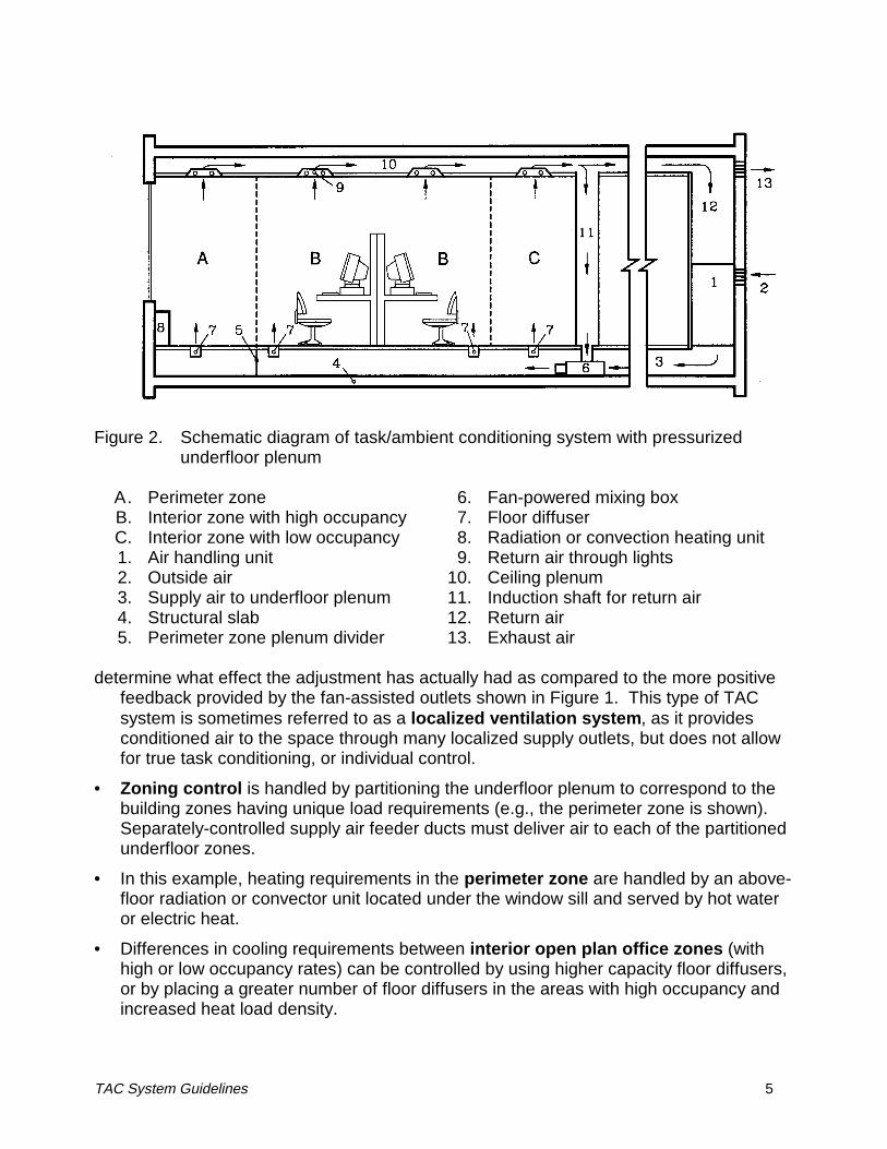
Figure 2. Schematic diagram of task/ambient conditioning system with pressurizedunderfloor plenum
A.B.C.1.2.3.4.5.
Perimeter zoneInterior zone with high occupancyInterior zone with low occupancyAir handling unitOutside airSupply air to underfloor plenumStructural slabPerimeter zone plenum divider
6.7.8.9.
10.11.12.13.
Fan-powered mixing boxFloor diffuserRadiation or convection heating unitReturn air through lightsCeiling plenumInduction shaft for return airReturn airExhaust air
determine what effect the adjustment has actually had as compared to the more positive
feedback provided by the fan-assisted outlets shown in Figure 1. This type of TACsystem is sometimes referred to as a localized ventilation system, as it providesconditioned air to the space through many localized supply outlets, but does not allowfor true task conditioning, or individual control.
• Zoning control is handled by partitioning the underfloor plenum to correspond to thebuilding zones having unique load requirements (e.g., the perimeter zone is shown).Separately-controlled supply air feeder ducts must deliver air to each of the partitionedunderfloor zones.
• In this example, heating requirements in the perimeter zone are handled by an above-floor radiation or convector unit located under the window sill and served by hot wateror electric heat.
• Differences in cooling requirements between interior open plan office zones (withhigh or low occupancy rates) can be controlled by using higher capacity floor diffusers,or by placing a greater number of floor diffusers in the areas with high occupancy andincreased heat load density.
TAC System Guidelines 11
Limitations
There exist some issues (both real and perceived) that limit the current application oftask/ambient conditioning technology. These are summarized briefly below.
1. New and unfamiliar technologyFor the majority of U.S. building owners, developers, architects, engineers, andequipment manufacturers, TAC systems still represent a relatively new and unfamiliartechnology. The decision to select a TAC system will initially require changes incommon practice, including new procedures and skills in the design, construction, andoperation of such systems. This situation creates some amount of perceived risk todesigners and building owners. A designer may incur added up-front costs associatedwith selling the idea of TAC technology to the client. Utility incentive programs couldhelp to compensate designers of energy-efficient TAC systems for any higher firstcosts during the design phase of a project.
2. Perceived higher costsAn industry survey found the perceived higher cost of TAC systems to be one of thetwo top reasons that TAC technology is not used more widely by the industry today[Bauman et al. 1992]. Many designers immediately eliminate underfloor TAC systemsfrom consideration out of concern for higher first costs of the raised access flooring.However, as described above, there are many factors associated with raised accessfloor systems that contribute to reduced life-cycle costs in comparison to traditional airdistribution systems. In TAC systems using fan-powered supply diffusers, theadditional cost of installing and maintaining these many small units must be balancedagainst the benefits of providing personal environmental control (reduced occupantcomplaints) and reducing the size of other system components (e.g., central fan).
3. Limited applicability to retrofit constructionThe installation of TAC systems and the advantages that they offer are most easilyachieved in new construction. Some of the key system features are not always suit-able for retrofit applications (e.g., access floors cannot be installed in existing buildingswith limited floor-to-floor heights). Due to the tremendous size of the existing buildingstock, retrofit construction will play a dominant role in the future for the buildingindustry. To gain greater acceptance, interest, and market-share, TAC systems andapproaches that can be more widely applied to retrofit installations are needed.
4. Lack of information and design guidelinesAlthough in recent years there have been an increased number of publications on TACtechnology (see References and Additional Reading), there still does not exist a set ofstandardized design guidelines for use by the industry. Designers having experiencewith TAC systems have largely developed guidelines of their own. The intent of thisguide is to address this lack of information describing TAC technology. In addition, asmore installations are completed and performance data become available, the benefitsof well-designed TAC systems should become apparent and greater acceptance andapplication of TAC technology will result.
12 TAC System Guidelines
5. Potential for higher building energy useAs with any space conditioning system, a poorly designed and operated TAC systemhas the potential to use more energy than that used by a well-designed conventionalsystem approach. System control issues can be very important in this regard and arediscussed in the section on Controls and Operation; the section concludes with a list ofrelevant topics in need of future research to improve the overall system performance ofTAC systems. The section on Energy Use discusses the ways in which TAC systemscan impact overall building energy use. For example, the energy use of TAC systemsusing large numbers of small local fans may increase due to the relatively poor fanmotor efficiencies in these units. One of the main objectives of this document is toprovide guidance for the proper implementation of TAC systems to avoid unnecessarilyhigh energy use.
6. Limited availability of TAC productsOnly a few manufacturers currently offer TAC products (discussed later in TACEquipment). As mentioned earlier, the Japanese have been quite active in developingTAC technology during recent years leading to a greater variety of advanced TACproducts offered by several of the Japanese construction companies (e.g., partition-based supply outlets, remote controllers for occupant use, packaged air handling unitsconfigured to fit within a “service wall”) [Tanabe 1995]. Additional products are stillneeded, however, to stimulate the market and address alternative promising designconfigurations.
7. Lack of standardized method for performance evaluation of TAC systemsExisting building standards, such as ASHRAE Standard 55-92 [ASHRAE 1992] forthermal comfort and ASHRAE Standard 113-90 [ASHRAE 1990] for room air diffusion,are based on the assumption of a single uniformly-mixed indoor environment. Thesestandards are not necessarily directly applicable to TAC systems that not only providefor thermal nonuniformities, but actually may encourage them. Efforts are nowunderway to revise these standards in part to ensure compatibility with TAC systems.
8. Cold feet and draft discomfortUnderfloor TAC systems are perceived by some to produce a cold floor, and becauseof the close proximity of supply outlets to the occupants, the increased possibility ofexcessive draft. These conditions are primarily indicative of a poorly designed andoperated underfloor system. Typical underfloor mixed air temperatures are above17°C (63°F) and nearly all office installations are carpeted so that cold floors are not aproblem. Individually controlled supply diffusers allow occupants to adjust the local airflow to match their personal preferences and avoid undesirable drafts.
9. Problems with spillage and dirt entering underfloor air distribution systemsAlthough widely applicable, there are areas in buildings where access floors and un-derfloor air distribution are not appropriate. These areas are generally those in whichspillage has the potential to occur, including bathrooms, laboratories, cafeterias, andshop areas. In TAC systems with floor diffusers, concern is sometimes expressedabout the increased probability of spillage and dirt entering directly into the underfloorsupply air stream, and therefore being more widely distributed throughout the occupied
TAC System Guidelines 13
space. Most floor diffusers, however, have been designed with catch-basins (e.g., tohold the liquid from a typical soft drink spill). Tests have shown that floor diffusers donot blow more dirt into the space than other air distribution systems, and in fact,contaminant levels are generally lower in underfloor TAC systems with a floor-to-ceilingair flow pattern [Matsunawa et al. 1995]. In addition, air speeds within the underfloorplenum are so low that they do not entrain any dirt or other contaminants from theplenum surfaces into the supply air.
10. Condensation problems and dehumidification in underfloor air distributionsystemsIn humid climates, outside air must be properly dehumidified before delivering supplyair to the underfloor plenum where condensation may occur on the cool structural slabsurfaces. While humidity control of this sort is not difficult, given the large surface areaof the structural slab in the underfloor plenum, it is important that it be done correctly.If a higher cooling coil temperature is used (allowing an increased chiller efficiency) toproduce the warmer supply air temperatures needed in TAC systems, the cooling coil’scapacity to dehumidify will be reduced. Possible solutions include the use of aseparate system to dry outside air or the use of desiccant dehumidification [Houghton1995].
Organization of Guide
The material presented in this guide is organized into the following sections:
Task/Ambient Conditioning System Design describes the basic elements of TACsystems, the tradeoffs between different approaches, system integration issues, anddifferences between traditional HVAC system design.
Room Air Distribution describes the benefits of the typical room air distributionprovided by TAC systems.
Standards and Codes reviews the applicable building standards and codes anddiscusses their compatibility with TAC technology.
Task/Ambient Conditioning Equipment describes the range of TAC products thatare currently available.
Controls and Operation discusses control strategies for the optimal and energy-efficient operation of TAC systems.
Energy Use summarizes the major system design and operation issues that promotethe efficient energy performance of TAC systems.
Design and Construction reviews issues associated with the design and constructionphases for TAC systems.
System Costs describes the key economic considerations associated with first costs,installation costs, and operation and maintenance costs of TAC systems.
Within each section a specific list of recommendations is included with a discussion of theissues.
14 TAC System Guidelines
TAC System Guidelines 15
TASK/AMBIENT CONDITIONING SYSTEM DESIGN
Recommendations
1. When possible, use an underfloor air distribution system (raised access floor) due toadvantages in reduced ductwork, reduced static pressures (reduced distributionlosses and lower central fan energy use), reconfigurability, and convenient distributionof building services.
2. For cooling applications, supply outlet temperatures should be maintained no lowerthan in the range of 17°C to 20°C (63°F to 68°F). This can be done in combinationwith the recirculation of a portion of the return air directly into the underfloor plenumor all the way back to the air handling unit.
3. Air should be returned at ceiling level. Depending on the ceiling configuration, this
can be done using a conventional ceiling return plenum, ducted return (concealed orexposed), or high side-wall return.
4. If the return air is recirculated directly into the underfloor plenum, it is very importantto ensure that the supply and return air streams are well mixed within the underfloorplenum before delivery to the space. This can usually be satisfactorily accomplishedby distributing the primary air at regularly-spaced intervals throughout the plenum.Shute (1995a) recommends distribution intervals of no greater than 9 m (30 ft). Theuse of fan-powered local supply units will aid the mixing of primary supply air with thereturn air.
5. Within the underfloor plenum, utilize the thermal storage capacity of the structuralmass to reduce peak cooling demand and downsize the cooling equipment, if climateconditions permit.
6. As described below, the low-pressure underfloor HVAC system [Spoormaker 1990]and the pressurized underfloor air supply system [Sodec and Craig 1991] have ad-vantages and disadvantages in comparison to each other. Both have been quitewidely and successfully installed.
7. In retrofit applications where floor-based systems are not possible, supply units mustbe able to accommodate connection to an existing overhead air distribution system.
8. Desktop- and partition-based systems should be well-integrated into the design of theoffice furnishings and compatible with an underfloor air distribution system.
9. Consider using a combination of supply outlet configurations to more closely matchspatially varying conditioning requirements. To most effectively achieve task andambient control, it is recommended to use one air distribution system, but differentiatebetween task and ambient supply diffusers.
10. In new construction, consider using multiple medium to small-sized (floor-by-floor) airhandling units to minimize or totally eliminate ductwork and provide improved zone
16 TAC System Guidelines
control by more closely matching the AHU capacities with the requirements ofseparate underfloor plenum zones.
11. A variety of conventional approaches to the treatment of perimeter heating andcooling loads can be used.
12. When underfloor air heating methods are used, supply air should be ducted from thefan-powered mixing box to the supply diffuser to allow quick response on calls forheating. The occupied zone of the space is heated very efficiently when warm air isdelivered at or near floor level.
Discussion
System ConfigurationIn configuring a TAC air distribution system, the basic choices include: (1) underfloorplenum supply at low pressure in combination with low-powered fans to bring this air intothe space; (2) pressurized underfloor plenum supply; (3) ducted supply, either through anunderfloor plenum or in combination with traditional overhead duct design; and (4) somecombination of the above. It is highly recommended to use an underfloor supply plenumwhen possible, particularly in new construction. Fewer options are available for retrofitapplications in which there are no opportunities for underfloor air distribution. In thesecases, existing overhead air distribution systems must be modified and ducted to localizedsupply diffusers. Underfloor air distribution systems have been the most widely appliedTAC system and we have relied upon the experience gained from these installations in thediscussion presented below.
Underfloor Air DistributionTraditional HVAC system design is based on the delivery of conditioned air directly to thespace through extensive duct networks. This configuration presents several advantagesto the design engineer, including the following: (1) direct connection to the supply outletsmakes centralized control more convenient; (2) air flows can be more easily measuredand controlled because of the relatively high pressure drops in the distribution system; (3)first costs are generally, although not always, lower than those for TAC systems, however,duct costs can be substantial; and (4) there is great familiarity with ducted systems, and alarge selection of available system components.
The selection of a raised access floor system for a modern office building, despite per-ceived higher first costs, is often made for one or more of the following reasons: (1) im-proved power and communication cable management; (2) use of the sub-floor area as asupply plenum for a floor-based TAC system; (3) flexibility and reduced costs associatedwith reconfiguring building services including the location of air supply outlets duringremodeling over the lifetime of the building; and (4) in new construction, potential forreduced floor-to-floor heights. In a well-designed new office building with an underfloor airdistribution system, because of the increased space available below the floor for air supplyin comparison to a conventional ducted ceiling-based system, it is possible for the overallheight of service plenums (underfloor plenum for air supply and most building servicesplus a smaller ceiling plenum for air return, electric lighting, and fire sprinklers) to be
TAC System Guidelines 17
reduced. The reduction of floor-to-floor heights, particularly in high-rise construction, is avery strong cost incentive for building owners and developers. One noteworthy underfloorapproach being developed in Japan uses a very small (100 mm [4 in.]) underfloor plenumheight [Tanabe 1995], although plenum heights are more commonly in the range of 0.3 mto 0.46 m (12 in. to 18 in.).
Underfloor air distribution systems have additional advantages over conventional ductedoverhead systems. Use of the space below the floor as a supply plenum eliminates theneed for a significant amount of ductwork, and reduces static pressures for the central airhandling unit, thus decreasing distribution losses and reducing fan energy use. Since floorsupply outlets can be easily rearranged by adding, subtracting, or simply moving floorpanels, the spatial distribution of supply air can be adjusted to match nonuniform andabove-average cooling demands that often occur in today’s office environment.
Supply Air Temperature and VolumeFor cooling applications, all underfloor air distribution systems installed in interior zones ofoffice buildings and other heavily occupied spaces are designed to maintain supply outlettemperatures no lower than in the range of 17°C to 20°C (63°F to 68°F). The requiredsupply outlet temperatures, as with any localized system, must be in this warmer rangecompared to conventional overhead systems (10°C to 16°C [50°F to 60°F]) to avoidovercooling nearby occupants. Under suitable climate conditions, this greatly increasesthe availability of outside air economizer use and also allows higher coil temperatures tobe used if desired, thereby increasing chiller efficiencies. To maintain these warmersupply air temperatures, several design approaches have been used.
1. Under constant or variable volume control, cool primary air is mixed with warm by-passed return air at the air handler to produce supply air of the proper temperature andhumidity before being delivered directly into the underfloor plenum. In this con-figuration, a range of coil temperatures can be specified, including low temperature airsystems using ice storage.
2. The air handler delivers cool primary air directly into the underfloor plenum, where it ismixed with warm return air from the space to produce the desired average plenumtemperatures. In climates where humidity control is required, cooling coil temperaturesare typically in the range of 10°C to 13°C (50°F to 55°F), requiring that thorough mixingof primary and return air take place in the underfloor plenum. Delivering coolertemperature air directly into the underfloor plenum is not advisable out of concern forovercooling the plenum and producing uncomfortably cool supply air temperaturesnear building occupants.
3. Other less efficient versions of the underfloor system utilize reheat to maintain thedesired plenum supply temperatures.
For additional discussion of the methods used to mix return air with primary air, refer to thenext section on Return Air.
Since underfloor air distribution systems allow properly controlled stratification to exist inthe space, return air temperatures are significantly higher than those found in conventionalsystem design. Depending on the space cooling load, the ceiling-level return air

18 TAC System Guidelines
temperature is typically 8°C to 10°C (15°F to 18°F) above the floor-level supply air tem-perature. In comparison, a ceiling-based mixing-type air distribution system would supply13°C (55°F) air and return 24°C (75°F) air. This comparison shows that total supply airvolumes for underfloor systems will average approximately 10-30% higher than con-ventional supply air volumes for the same cooling load. However, primary supply airvolumes can be reduced in well-designed systems that condition only the minimumamount of outside air for overall cooling and ventilation purposes and rely on high rates ofrecirculated air driven by fan-powered supply diffusers for additional occupant cooling. Insuccessful designs of this type in South Africa, Spoormaker (1990) claims to have beenable to reduce primary air quantities for interior zones to 25% to 30% of those required fora conventional all-air design.
Due to the significantly lower pressures in underfloor plenum supply systems relative toconventional ducted systems, it can be more difficult to control the central air handler on avariable air volume (VAV) basis. These low pressures are generally below the rangeaccurately measured by the typical velocity/pressure sensors used in ducted systems.Alternative control methods have therefore been devised and are described in Controlsand Operation.
Return AirAir is typically returned at ceiling level in a TAC system. For underfloor air supply andother configurations that deliver air close to floor level, this floor-to-ceiling air movement inthe space can lead to benefits associated with controlled stratification and improvedventilation effectiveness in the occupied zone. Depending on the ceiling configuration, aircan be returned using a conventional ceiling return plenum, ducted return (concealed orexposed), or high side-wall return. As in any type of HVAC system, a certain amount ofreturn air from the space may be recirculated and mixed with the incoming fresh outsideair to conserve energy.
A common strategy with underfloor air distribution is to recirculate a portion of the returnair, or room air close to ceiling level, directly back into the underfloor plenum where it isthoroughly mixed with the cool primary air to produce the desired supply air temperaturefor the floor diffusers (see Figures 1 and 2). In the low-pressure plenum system, thesupply volume provided by the central air handler is typically less than the total volumeprovided to the space through the fan-powered supply diffusers. In this arrangement thediffusers induce return air from the space to be mixed with the primary air in the plenum.Return air can be drawn down induction shafts from the ceiling return plenum, or simplythrough floor-level equalizing grills from the room into the underfloor plenum. Thepressurized plenum system requires a more conventional ducted fan-powered mixing boxto combine return and primary air before delivering it into the sub-floor plenum (see Figure2). In any case, the proper mixing of the supply and return air is an important factor forsuccessful operation of this underfloor system design as it avoids delivering uncomfortablycool supply air to the space. This strategy reduces costs and loss of building volumerequired to contain the recirculating ductwork, particularly when a central system design isused.

TAC System Guidelines 19
An alternative approach is to take all of the return air back to the air handler where theamount to be recirculated can be filtered, bypassed around the coil or conditioned (ifnecessary), and then mixed with the conditioned incoming outside air before delivery tothe underfloor plenum. This second approach provides for optimal control of supply airconditions in terms of temperature and humidity, filtering, and mixing. It is best appliedwhen smaller floor-by-floor air handlers are part of the design, thus reducing the length ofrecirculating ductwork.
As discussed later in Room Air Distribution, the ventilation efficiency of a TAC systemusing floor-to-ceiling air flow should be slightly higher than for a conventional ceiling-basedmixing-type air distribution system. If minimum outside air quantities are used incombination with larger return air quantities to maintain adequate room air velocities andtemperatures, savings can be realized in central fan energy use and in reduced primaryduct sizes.
Thermal StorageFrom an energy savings standpoint, one of the most important features of the underfloorsystem may be the use of the mass of the structural slab (and access floor panels) as athermal storage medium. Due to the good thermal contact that is possible between theplenum supply air and the building structure, it is possible to implement a control strategythat utilizes a 24-hour cycle of the thermal mass to reduce energy use, peak power, andoperating costs. One note of caution, however -- in humid climates, outside air must beproperly dehumidified before delivering supply air to the underfloor plenum wherecondensation may occur on the cool structural slab surfaces. While humidity control ofthis sort is not difficult, given the large surface area of the structural slab in the underfloorplenum, it is important that it be done correctly.
1. During the summer, the structural mass can be subcooled during nighttime hours, andthen used to offset a portion of the peak cooling loads the following day. If the localutility rate structure has incentives for load shifting, the reduced peak electrical demandwill produce savings in operating costs. This can be quite significant, as Spoormaker(1990) estimates up to a 40% reduction in summer peak demand for interior zonesusing a thermal storage strategy. Based on observations in an existing installation,Shute (1995a) estimates that enough thermal mass participates in a daily temperaturevariation cycle of 3.3°C to 3.9°C (6°F to 7°F) to allow storage of approximately 30% ofa typical daily cooling load. Also, by running the cooling plant for 24 hours to handlethe load, equipment can be downsized.
2. When ambient nighttime temperatures are low enough, particularly during winter andswing seasons, nighttime flushing with cool outside air can subcool the thermal mass,thus reducing the amount of mechanical refrigeration needed for the following day'scooling load. This nighttime economizer operation extends the "free cooling cycle" incomparison to conventional HVAC systems designed to meet instantaneous daytimecooling loads. An example of this application has been described by Matsunawa et al.(1995). Of course, the overall usefulness of this strategy depends on the temperatureand humidity characteristics of the local climate. One must be cautioned that in winterthe cool thermal mass can aggravate the need for heating during the first hours of

20 TAC System Guidelines
occupancy, particularly in perimeter zones, before internal loads take effect andcooling is needed for the remainder of the day.
3. During the winter and in climates where some amount of nighttime heating is required,the heat gain stored in the mass during the day can act to preheat the supply air priorto reheating (using electric or water-based fan coil units) at the supply outlets duringthe following night.
Underfloor Air Distribution System ApproachesThe two principal types of underfloor air distribution systems are compared below. (1) Inthe low-pressure underfloor HVAC system, as described by Spoormaker (1990) and Shute(1995a), primary air from the central air handling unit is delivered to the sub-floor plenumat very nearly the same pressure as the conditioned space. Air is delivered to the spaceprimarily through floor-based fan air terminals. (2) The second approach uses apressurized sub-floor plenum in which the central air handler forces the supply air throughfloor air outlets (no local fans) into the occupied space [Sodec and Craig 1991, McCarry1995].
The low-pressure plenum system allows the majority of the sub-floor space to be openand relies on the controllable local fan air terminals to provide variations in supply con-ditions as needed. The fan-powered supply diffusers maintain consistent air flow into theconditioned space, even when the underfloor plenum is opened for maintenance andother purposes. Because of the increased capacity to provide local cooling as neededfrom fan-powered supply diffusers, some designers prefer to specify the low-pressureplenum system for applications involving higher heat loads. In these cases, the higherheat loads are commonly due to larger amounts of electrical equipment, often requiringmore access holes through the floor to accommodate wiring. Uncontrolled leakage ofconditioned air through access holes in the floor, to the outside, or to adjacent controlzones are eliminated with this approach. As discussed later in Standards and Codes,some amount of partitioning may be required by local fire codes in all underfloor supplyplenum designs.
The pressurized plenum system is designed to provide similar supply conditions throughall floor outlets of the same size (several models are available), and thus requires parti-tioning of the underfloor space to accommodate building control zones with significantlydifferent thermal loads. When the underfloor plenum is subdivided, the system is usuallyconfigured to satisfy all cooling loads with the central plant and not with local fan coil units.Although they are routinely used, plenum dividers add complexity to the underfloorconfiguration, cause headaches for electricians and other service personnel, and inpressurized systems pose the possibility of leakage between separate plenum controlzones. Due to the relatively low pressure (≤ 25 Pa [0.10 in. H2O]) used in the pressurizedunderfloor supply air plenum, however, Sodec and Craig (1991) claim that leakage intoadjacent zones is small. Pressurized underfloor systems can experience problemscontrolling air flow through the supply outlets when sections of the access floor panels aretaken up for rerouting cables, repair, or cleaning, or if distances are too great betweenprimary air inlet locations and supply diffusers. On the other hand, pressurized systemsdo not need to rely on smaller local fans (except in the use of fan-powered mixing boxes)
TAC System Guidelines 21
to distribute the supply air to the conditioned space. See Energy Use for more discussionon fan energy issues.
The reliability of low-pressure plenum systems with fan-powered supply diffusers is im-proved in comparison to the central fan-driven (pressurized plenum) approach becausethe low-pressure system design incorporates two or three independent subsystems, asdescribed by Spoormaker (1990) below:
1. The primary air ventilation system satisfies all minimum ventilation and humidity controlrequirements and a portion of the daily cooling and heating loads. The primary airsystem is also responsible for pre-cooling the building thermal mass in the underfloorplenum during the nighttime with outside air (if weather conditions permit) or withmechanically-cooled air.
2. Floor-based fan air terminals serve as the localized supply units under occupantcontrol (typically one unit is located adjacent to each work location) and also providegeneral space cooling under automatic control. The fan terminals draw conditioned airfrom the underfloor plenum and deliver it to the space.
3. Water-based fan coil units (or other means as discussed in Perimeter Systems) areused to remove the excess heating and cooling loads that cannot be satisfied by theother subsystems. These units are most commonly positioned in the underfloor ple-num of the perimeter zones of the building, and are controlled by a local spacethermostat.
The above design approach has proven to be reliable because even if one of the sub-systems goes down, the others can still operate to provide partial comfort control. Forexample, as discussed by McGregor (1995), if the chiller or central air handler goes down,some cooling effect will still be maintained by the fan-powered floor diffusers as they drawsupply air over the cool floor slab and also increase local room air movement for occupantcooling.
Desktop- and Partition-Based Supply DiffusersIn desktop- and partition-based TAC systems, some amount of ductwork or passagewaysin and around the furniture must be used to deliver the supply air to the outlet locations,increasing the complexity of these installations. Primary air can be provided by some sortof downshaft connected to a conventional ducted ceiling-based air distribution system,making these diffusers compatible with retrofit applications. For many of the samereasons discussed above, however, connecting to an underfloor air distribution system ispreferred. The widespread use of repeatable patterns of partitions and furniture in openplan offices presents an opportunity to develop TAC system designs that are wellintegrated into the office furnishings. Just as a floor-based TAC system is easilyadaptable to different configurations, a desk- or partition-based system that can be"plugged into" specially-designed access floor panels can reduce installation costs andincrease flexibility (see Figure 1). Several partition-based TAC systems have beenrecently developed in Japan. Some examples are described by Hisaki et al. (1991),Imagawa and Mima (1991), Tanago and Takeda (1991), Tanaka (1991), and Matsunawaet al. (1995).
22 TAC System Guidelines
The possible locations of furniture-based supply outlets with respect to the building oc-cupants are tied closely to the layout of the office interior. In open-use areas with feweroptions for furniture-based installations, it may be necessary to use floor-based (or other)supply configurations. In the same manner, an effective strategy for laying out the supplylocations and outlet types throughout the space may be to consider a combination ofdifferent outlet designs. For example, while floor-based or furniture-based supply unitswith jet flow characteristics may be acceptable under occupant-controlled conditions, ahigh mixing floor (swirl) diffuser may be preferred in open areas with no opportunity foroccupant control.
Task/Ambient System Integration IssuesThe design of a TAC system is like that of any HVAC system in that it must satisfy peakcooling and heating demands, as well as maintain comfort across zones with spatiallyvarying cooling and heating loads. The effectiveness of the design will depend to a largeextent on how well the task and ambient environmental control functions of the building’sHVAC system are integrated together. TAC system configurations can be divided into twoprimary types, in which the control and operation of the task and ambient spaceconditioning functions may vary significantly.
1. When task and ambient control functions are designed as two distinct air distributionsystems, the task system is operated in conjunction with the ambient space condi-tioning system, being used only when the building occupants desire local conditions tobe different from ambient conditions. This configuration requires that system inte-gration issues be considered carefully. In the most basic, and probably least effective,approach, the centrally-controlled ambient space conditioning system operates inmuch the same manner as in a stand-alone conventional HVAC system, maintaininguniform conditions throughout the building without any adjustment in response to theoperation of the task system. In this scenario, the task, or local, conditioningcomponents will tend to be expensive and underutilized additions to the buildingsystem, because only a relatively small percentage of the occupants will have a needto modify their local environment. This situation can occur in retrofit installations inwhich the task system is simply added to the building, but the existing conventionaloverhead system is still operated in the same manner as it was before the task systemwas installed.
TAC System Guidelines 23
Using a more sophisticated approach, however, overall system performance will beimproved by taking advantage of advanced control strategies that allow some degreeof feedback between the operation of the separate task and ambient systems. Forexample, in a TAC system with fan-powered local supply units, information about thenumber of local units on or off combined with the current ambient space temperaturecan allow appropriate adjustments to be made, such as resetting the task or ambientsystem supply temperature or volume setpoints [Imagawa and Mima 1991].
2. The second type of system configuration involves the use of one air distribution systemfor both task and ambient control functions. In this approach, air may be deliveredthrough the same type of local supply outlets for both personal comfort control and theremoval of the major building loads. Underfloor air distribution systems with floorsupply grills often fall into this category. Compared to the first option described above,costs for this configuration will be lower and overall system controls will tend to be lesscomplex. However, if occupant use patterns produce widely intermittent operation oflocal supply units, temperatures and air circulation in the building may be uneven, asdiscussed by Tanaka (1991). Underfloor TAC systems that allow only small amountsof occupant control (see Figure 2) are able to minimize these undesirable effects andprovide relatively uniform conditions, except in the immediate vicinity of the floordiffusers, which are considered to be only temporarily occupied spaces [Sodec andCraig 1991].
Probably the best approach in terms of performance is to use one air distributionsystem, but differentiate between task and ambient supply diffusers. When localsupply diffusers contain variable speed fans, sophisticated control strategies can beaccomplished, approaching those possible with two distinct task and ambient systems.In one variation of this configuration, the volume of underfloor supply air is controlledbased on a room thermostat. This supply air is delivered up through and out the top ofthe office partitions. Office workers can divert a portion of this supply air to control theirlocal environment, but the total volume delivered to the local space remains under thecontrol of the thermostat, not the occupant [Argon 1994]. See Task/AmbientConditioning Equipment for more specific details of these systems.
In principle, the same central or floor-by-floor HVAC system equipment can be used as inconventional air distribution systems, making the selection of this equipment routine. Innew multi-story construction, the use of medium to small-sized floor-by-floor air handlingunits in combination with underfloor air distribution has advantages over central airhandlers in terms of minimizing or almost completely eliminating major ductwork. SmallAHUs also provide improved zone control capabilities and can be more easily matched insize with separate underfloor plenum zones (created by underfloor partitions) oftenrequired by local fire codes. See additional discussion in Standards and Codes.
24 TAC System Guidelines
Perimeter SystemsThe additional heating and cooling loads of perimeter zones can be handled with con-ventional approaches using dedicated equipment. The treatment of perimeter loadsshould always be combined with an energy-efficient design of the building envelope (e.g.,advanced glazing, shading, and daylighting strategies) to minimize the adverse impact ofexternal weather conditions. A variety of perimeter systems have been used with TACsystems (for example, see Shute 1995a and McCarry 1995). Water-based fan coil unitsand heat pumps have several advantages. Water distribution serving these units hassmall space requirements and can be conveniently delivered through the underfloorplenum. Thermal distribution with water, in comparison to air distribution, saves energybecause pumping water is more efficient than moving air. On the other hand, manydesigners and maintenance personnel are uncomfortable with the use of cooling coils withthese units because it requires condensate pans and drains in the underfloor plenum.Nevertheless, these systems have been successfully installed and operated.
Approaches to perimeter cooling have been used that eliminate the need for water-basedcooling under the floor by relying on the cool underfloor air reservoir under variable volume(and temperature) control. In low-pressure plenums, a fan-powered VAV box draws airfrom the underfloor plenum to be used in this regard (see Figure 1), and in pressurizedplenums, the underfloor plenum is divided into a separate perimeter zone in which thevolume and temperature of the supply air ducted from the air handler is controlled to meetthe perimeter cooling loads (see Figure 2).
For perimeter heating requirements, a variety of approaches can be used, depending ondesign and cost considerations. Electric or water-based reheat coils can be added to fan-powered VAV boxes (see Figure 1). In this case, supply air should be ducted from theVAV box to the floor diffuser to avoid having to heat up the exposed thermal mass in theunderfloor plenum and allow quick response on calls for heating. Separate above-floorheating methods can also be used, such as electric base-board heaters, radiation orconvector units under the window sill (see Figure 2), or radiant ceilings. The occupiedzone of the space is heated very efficiently when warm air is delivered at or near floorlevel, and the risk of short-circuiting between supply and return is greatly reduced.
During the winter in open plan offices, the situation often occurs in which heating is re-quired in the perimeter zone simultaneously with cooling requirements in the interior zoneof the building driven by the typical high density of heat sources. This can lead to mixingenergy losses between the two zones. This subject has been studied in detail byNakahara and Ito (1993a, 1993b), who discuss useful design and control strategies tominimize mixing energy losses.
TAC System Guidelines 25
ROOM AIR DISTRIBUTION
Recommendations
1. For cooling applications, take advantage of the benefits of the upward moving room aircaused by supplying air at or near the floor level and returning it at ceiling level. Thisair flow pattern can lead to energy savings associated with controlled stratification andpotentially improved ventilation and contaminant removal effectiveness in the occupiedzone.
2. Optimize the range of allowable cooling supply air conditions from diffusers to limit theirimmediate impact to the occupied zone of the space (up to 1.8 m [6 ft] height). Thisstrategy permits increased air velocities and mixing to occur within the occupied zone,if desired for comfort, but avoids a completely well-mixed space, as is typicallyproduced by an overhead air distribution system. Allow temperatures and contaminantlevels to increase above the occupied zone.
3. For air heating applications, deliver warm air at or near floor level to take advantage ofthe improved heating efficiency of the occupied zone and the reduced risk of short-circuiting between supply and return (a common concern with ceiling-based supply-and-return systems).
Discussion
In California and many parts of the U.S., the vast majority of interior office space requiresyear-round cooling. In comparison to traditional mixing-type overhead air distributionsystems, underfloor systems have advantages for cooling applications for several reasons.Typically, in TAC systems cool and fresh conditioned air is delivered to the occupied zoneof the space at floor or desk level and is extracted at ceiling level. This overall upwardmovement of air in the room takes advantage of the natural buoyancy caused by heat gainto the space and produces a more stable and efficient room air flow pattern. The upward-moving room air distribution has the following characteristics. (1) Warm air rises into theregion above the occupied zone, some exiting the space with only partial mixing with theroom air. This air flow pattern creates a temperature stratification in the space leading toreductions in the cooling load by as much as 15% in comparison to a conventional ceiling-based system [Shute 1992]. (2) Space contaminants tend to also migrate upwardsproducing higher concentrations in the warm stratified air near the ceiling. (3) The floor-to-ceiling air flow pattern adapts naturally to locally high heat loads as the stronger thermalplume rising above these larger heat sources entrains additional cooler room air from lowelevations in the space surrounding the heat sources.
A major perceived disadvantage of TAC systems in comparison to traditional overheadsystems is that task supply diffusers can produce local areas in the occupied zone of thebuilding that are outside of the thermal comfort zone, as specified by comfort standards[ASHRAE 1992, ISO 1984]. On the other hand, ceiling-based air distribution systemsproduce this area outside of the occupied zone (i.e., near the ceiling). By allowing
26 TAC System Guidelines
individuals to adjust the local supply diffusers to satisfy their personal comfort preferences,however, TAC systems largely eliminate this perceived limitation.
Laboratory experiments with both floor-based and desktop-based TAC systems haveshown that the ventilation efficiency can be improved in comparison to mixing-type airdistribution at the worker’s breathing level in the occupied zone when the percent outsideair is high and when supply air is directed towards the work location [Fisk et al. 1991,Faulkner et al. 1993, Faulkner et al. 1995]. Similarly, Yokoyama and Inoue (1991, 1994)studied both the low-pressure and pressurized underfloor air distribution systems (withfloor diffusers) in a laboratory, and found improved ventilation efficiency and contaminantremoval effectiveness in comparison to that of an overhead air distribution system. Oguroet al. (1995) describe a field study in which the performance of an underfloor air-conditioning system on one floor was compared to the performance of a ceiling-based air-conditioning system on another floor of the same building. In this field study, airborneparticle concentrations were significantly lower for the underfloor air conditioning system.Additional experimental data are needed to more completely evaluate the ventilation andcontaminant removal effectiveness of various TAC system configurations.
For comparison with TAC system room air distribution, it is worth reviewing displacementventilation systems, which rely on the same upward movement of air in the room and havebeen widely used in Nordic countries, particularly in industrial applications. In adisplacement ventilation system, air is supplied at very low velocity through large-areasupply devices near floor level. Improved overall air exchange efficiency and ventilationefficiency in the occupied zone have been achieved at lower air supply volumes than withconventional ceiling-based mixing-type air distribution systems. Unfortunately, whenapplied to office configurations with high heat load densities (> 20-30 W/m2 [6.4- 9.5Btu/hr-ft2]) and reduced ceiling heights compared to industrial buildings, displacementsystems can not satisfy the cooling demand without imposing excessive thermalstratification in the space and overly cool conditions in the occupied zone. In response tothese comfort limitations recent research has suggested that higher air exchange ratesshould be used [Sandberg and Blomqvist 1989]. Svensson (1989) has suggested thathigher outlet velocities (although still relatively low) should also be used, producing greatermixing within the occupied zone and reducing the risk of comfort problems. By permittinggreater mixing to occur, air exchange and ventilation efficiency rates will not be as high asthose obtained with true displacement flow. However, if the mixing is confined to theoccupied zone (up to heights of 1.8 m [6 ft]), some amount of improvement in theefficiency of air exchange and ventilation can still be realized.
TAC systems differ from true displacement ventilation systems primarily in the way that airis delivered to the space: (1) higher air supply volumes are used, allowing higher coolingloads to be met, (2) air is supplied at higher velocity through smaller-sized supply outlets,and (3) local air supply conditions are generally under the control of the occupants,allowing comfort conditions to be optimized. Because of the more powerful air supplyflows with TAC systems, however, it is also possible to disrupt the stable upward flowpattern in the space. For example, previous laboratory experiments [Bauman et al. 1991a,Fisk et al. 1991] demonstrated that when the Tate Task Air Module (TAM) was operated athigher air supply volumes, the cool supply jets were able to reach the ceiling, therebyminimizing stratification and producing close to uniform ventilation conditions. While this
TAC System Guidelines 27
operating strategy of providing more complete mixing parallels that of conventionaloverhead air distribution systems, it reduces the potential improvements in energy andventilation performance described above. A preferred operating strategy for TAC systemswould limit the immediate impact of local air supply to room air conditions within theoccupied zone of the space, a subject discussed by Bauman et al. (1995).
28 TAC System Guidelines
STANDARDS AND CODES
Recommendations
1. Since TAC technology is relatively new to the building industry, its characteristics mayrequire consideration of unfamiliar code requirements and, in fact, may be in conflictwith the provisions of some existing standards and codes. Applicable standards andcodes should be looked at carefully; revisions and exceptions that are more compatiblewith TAC technology may be forthcoming as additional research results are obtained.
Discussion
Listed below are brief discussions of the applicable building standards and codes thathave important provisions related to the design, installation, and operation of TACsystems.
1. ASHRAE Standard 55-1992: Thermal Environmental Conditions for HumanOccupancy [ASHRAE 1992]Earlier versions of Standard 55 were based on the assumption of a well-mixed anduniformly conditioned environment. TAC systems, however, usually involve greatervariability of thermal conditions over both space and time. The effect of providingoccupant-control has not been fully taken into account, although it is well-establishedthat occupants will tolerate greater fluctuations in environmental conditions if they havecontrol over them. The rather strict air velocity limitations that were specified in theprevious version of Standard 55 were incompatible with the increased local airvelocities that are possible with TAC systems. The recently released ASHRAEStandard 55-1992 was revised to allow higher air velocities than the previous versionof the standard, if the occupant has control over the local air speed. Figure 3 inStandard 55-92 was added to show the air speed required to offset increases intemperature above those allowed in the summer comfort zone. For example, Figure 3indicates that at equal air and radiant temperatures (tr - ta = 0), a local air speed of 0.8m/s (160 fpm) can offset a temperature rise of about 2.6°C (4.7°F) for a primarilysedentary building occupant wearing 0.5 clo.
Standard 55-92 also specifies allowable air speeds as a function of air temperatureand turbulence intensity with the objective of avoiding unwanted drafts when the oc-cupant has no direct local control. As discussed by Fountain and Arens (1993), thedraft avoidance limits are solidly based on laboratory data for temperatures below 23°C(73.5°F). At warmer temperatures, however, occupants will desire additional cooling,and increased air movement (and turbulence) is an easy way of achieving such directoccupant cooling. Standard 55-92 allows these velocity limits based on turbulenceintensity level to be exceeded if the occupant has control over the local air speed.
2. ASHRAE Standard 62-1989: Ventilation for Acceptable Indoor Air Quality[ASHRAE 1989]Standard 62-89 provides guidelines for the determination of ventilation rates that willmaintain acceptable indoor air quality. Currently under revision, the new version of
TAC System Guidelines 29
Standard 62 is expected to allow some adjustment in ventilation rates based on the airchange effectiveness (ACE) of the air distribution system. Mixing-type air distributionsystems can at best achieve a perfectly-mixed space, defined to have an ACE of 1.0,as determined in accordance with the proposed ASHRAE Standard 129P (see below).By definition, mixing-type systems cannot provide preferential ventilation (ACE > 1), inwhich some credit could be obtained for improved air change effectiveness at thebreathing level in the space.
Standard 62 sets minimum ventilation rates for office space and conference rooms at9.4 L/s (20 cfm) per person and reception areas at 7.1 L/s (15 cfm) per person. In thedesign and operation of a TAC system containing a large number of occupant-controlled supply modules, some means must be provided to ensure that minimumventilation rates are maintained, even when people choose to turn off their local airsupply.
3. ASHRAE Standard 90.1-1989: Energy Efficient Design of New Buildings ExceptLow-Rise Residential Buildings [ASHRAE 1989]ASHRAE Standard 90.1 describes requirements for the energy efficient design of newbuildings intended for human occupancy. In section 9.5.2, the prescriptive criteria forzone controls states that there can be no simultaneous operation of heating andcooling systems to the same zone. Some of the unique aspects of TAC systems maybe in conflict with this requirement. For example, if occupants have control of supplyair temperature for heating or cooling from their local diffusers, situations may occur inwhich some people are requesting heating and others are requesting cooling at thesame time within the same zone. In another example, with underfloor air distributionusing a precooled structural slab, if there is a call for heating (i.e., in the early morninghours of the perimeter zone), this may require local reheating of the cooled underfloorsupply air to satisfy the heating demand. These and other relevant situations shouldbe carefully considered as there are exceptions to the criteria described in Standard90.1, and perhaps subtle differences in the operation of a TAC system compared to aconventional overhead air distribution system.
4. ASHRAE Standard 113-1990: Method of Testing for Room Air Diffusion [ASHRAE1990]ASHRAE Standard 113-90 is the only currently available building standard forevaluating the air diffusion performance of an air distribution system. The currentversion of Standard 113, however, is based on the assumption of a single uniformlymixed indoor environment, as provided by a conventional overhead air distributionsystem. This assumption is not necessarily appropriate for evaluating the performanceof TAC systems that deliver conditioned air directly into the occupied zone of thebuilding through supply outlets that are in close proximity to and under the control ofthe building occupants. TAC systems therefore not only provide for thermalnonuniformities in the space, but may actually encourage them. Efforts are now un-derway to revise Standard 113 to include a new section describing a method of testthat is applicable to TAC systems
30 TAC System Guidelines
5. Proposed ASHRAE Standard 129P: Standard Method of Measuring Air ChangeEffectiveness [ASHRAE in press]The proposed ASHRAE Standard 129P is currently a working draft and is intended toprovide a test method for evaluating an air distribution system’s ability to providerequired levels of ventilation air to the building occupants. The results of the tests maybe used to determine compliance with ASHRAE Standard 62. The possibility of takingcredit for the enhanced ventilation effectiveness provided at breathing level by TACsystems is now being investigated.
6. CEC Second Generation Nonresidential Standards [California Energy Com-mission 1988]The CEC Nonresidential Standards (Title-24) defers to applicable ASHRAE standardsin most cases. Title-24 does, however, address a few areas that should be taken intoconsideration in the operation of TAC systems. Title-24 mandates off-hour controls forcentral HVAC systems. Since some TAC systems are equipped with occupancysensors, they may, in fact, improve off-hour control by shutting down more often thanthe overall system. Title-24 requires thermostatic zone controls with adjustablesetpoints. Since TAC systems may maintain temperature differences between locallyconditioned zones (workstations) and unconditioned or centrally conditioned areas ofthe workplace (e.g., corridors), attention should be paid to placing zone controls inrepresentative locations. In general, Title-24 focuses on the effects of overall systems.As a result, the integration between the local and central controls should be carefullyconsidered. The effects of individual thermal preferences on overall air quality andcomfort should also be taken into account.
7. Uniform Building Code and Local Fire CodesThe combustibility of cabling (power, data, communication) contained in supply airplenums in underfloor air distribution systems is an important consideration. In gen-eral, applicable codes state that placing wires and cables in an air supply plenum is nota problem as long as they are contained in conduit, or are rated to be non-combustible.Local fire codes often place restrictions on the size of open supply air plenums withoutany smoke breaks in the form of partitions separating the plenum into smaller zones.Typically, these fire codes limit the total area (e.g., less than 280 m2 [3,000 ft2]) andhorizontal dimension in one direction (e.g., less than 9 m [30 ft]) of an unobstructedunderfloor air supply plenum.
TAC System Guidelines 31
TASK/AMBIENT CONDITIONING EQUIPMENT
Recommendations
1. Individual supply units and outlets should be controllable by building occupants toadjust their local thermal environments to satisfy their personal comfort preferences.At a minimum, occupants should have control over a suitably wide range of supplydirections and velocities. It is currently recommended that individually controllableunits supply up to at least 1–1.5 m/s (200-300 fpm) at the work location.
2. Local supply air may be driven either by local fans in combination with a central airhandling unit, or by a central air handler alone. Units containing fans will tend to havethe best performance in response to adjustments by occupants. Efficient and quietfan motors should be incorporated into these designs.
3. An occupancy sensor should be associated with each fan-powered occupant-con-trolled unit to monitor the presence of the office worker and to turn the unit off whenthe workstation is unoccupied. This can be an important energy saving feature aslong as it does not adversely affect the environmental control of the whole space.
4. Local controls should be accessible and easy to use by the office worker. For ex-ample, controls located on the desktop are preferred over those at floor level. In-convenient controls will not be used, defeating their main purpose. Information andtraining on the use of the controls should be readily available.
5. Supply outlets should be designed to perform in a manner that responds quickly andeffectively to occupant control. While diffusers with high induction ratios (e.g., swirldiffusers) reduce the risk of draft discomfort, jet diffusers may be preferred incircumstances where a broader range of local control is desired. In addition, thelocation of the supply outlet in relation to the user may affect acceptability. More dataon occupant satisfaction and use patterns with different systems are needed, and willpresumably be obtained as experience with these systems grows.
6. The minimum non-zero supply velocity of floor outlets should be low enough to allowoptimization of the system performance. Previous laboratory tests under coolingconditions have shown that for typical office loads, low to medium air flow rates canbe used to provide acceptable thermal comfort and potentially improved ventilationefficiency in the occupied zone, while allowing some amount of stratification toproduce a warmer upper zone, thus reducing space cooling energy use in com-parison to a “mixing’ type ventilation system [Bauman et al. 1995]. These reduced airflow rates are lower than are currently available in some floor supply outlet designs.Lower supply velocities can also lead to: (1) reduced draft risk, (2) more of adisplacement flow, producing increased stratification in the space and improvedventilation in the occupied zone, and (3) reduced noise levels.
7. It is recommended that supply units be compatible with an underfloor air distributionsystem. The advantages of this configuration have been discussed previously.
32 TAC System Guidelines
8. Despite the fact that they are often located close to the occupants, supply units mustbe able to maintain acceptable noise levels (equal or better noise control compared tothose provided by conventional diffusers) at the work locations. In underfloorsystems, floor supply outlets must control the entry of dirt and particulates into the airdistribution system.
9. To increase flexibility and reduce installation costs, supply units should be integratedinto the interior office design and be easily moved and maintained. Just as floor-based supply modules are incorporated into the access floor system, well-integrateddesktop- and partition-based systems could be quite valuable in an open-plan officeusing large quantities of the same partitions and desk configurations. Well-integrateddesigns will reduce costs associated with adapting to the changing requirements ofexisting or new tenants over the lifetime of the building.
10. The potential advantages of providing environmental control features beyond thebasic air supply direction and velocity (e.g., variable temperature, radiant heating,etc.) must be evaluated in relation to the added complexity, cost, and energy use ofsuch a system. Additional performance data are needed to resolve this issue.
Local Supply Units and Outlets
Currently, TAC supply outlet configurations can be categorized into four primary types:floor-, desktop-, partition-, and ceiling-based. For each of these categories, some of thecurrently available supply units and outlets from the leading manufacturers of TACequipment are briefly described below. Product listings are provided for information onlyand do not constitute a recommendation or endorsement.
Floor-Based SystemsFloor-based systems have been the most commonly installed types of TAC systems. Theoutlets are designed to be incorporated into a raised access floor system. Air is eitherdrawn from a low-pressure underfloor plenum by local variable or constant-speed fans, orforced through a pressurized underfloor plenum by the central air handler, and delivered tothe space through floor-level supply outlets. Floor-based TAC systems have beenpreviously developed and used in South Africa and Europe [Spoormaker 1990, Sodec andCraig 1991], and more recently in Japan [AIJ 1993, Nagoya University 1994, Matsunawaet al. 1995] and in North America [Shute 1992, Shute 1995a, McCarry 1995].
TAC System Guidelines 33
Figure 3. Task Air™ Module (courtesy of Tate Access Floors)
• Task Air™ Module (TAM) (Figure 3); available from Tate Access Floors, Inc., 7510Montevideo Road, Jessup, MD 20794; telephone: 410-799-4200.
Floor-based supply outlets can be positioned anywhere in the building as part of a raisedaccess floor system. Each TAM, measuring 0.6 m by 0.6 m (2 ft by 2 ft), can belocated at any position simply by exchanging it with a solid floor panel of equal size.Figure 3 shows a cutaway diagram of the TAM. A fan/motor assembly draws air fromthe subfloor plenum and supplies it to the room through four 127-mm (5-in.) diameterdischarge grills. The grills are molded of durable, fire-resistant polycarbonate.Individual vanes are inclined at 40° from vertical. A rotary speed control knob isrecessed into one grill and each grill can be rotated 360°, allowing office workers tocontrol both the direction and quantity of air supplied from the module.
When the fan is switched on, the TAM can deliver between 40 and 90 L/s (90 and 190cfm) from a zero or very low pressure plenum. Because of the local fan control and jetair discharge pattern, occupants can control their local thermal conditions over a widerrange than the Krantz system using swirl diffusers. However, if not properly controlled,draft discomfort can be more frequent. Results of performance testing are describedby Bauman et al. (1991a, 1995). Whole-building energy simulations are presented byBauman et al. (1994).
34 TAC System Guidelines
Figure 4. KB-200 floor diffuser (courtesy of Krantz)
• KB-200-ORH, KB-200 and KB-150 floor diffusers (Figure 4); manufactured by H.Krantz GmbH & Co., Aachen, Germany; available from Euro-Tech Products, Inc., P.O.Box 905, Monroe, NC 28111-0905; telephone: 704-483-2050
Floor-based supply outlets can be positioned anywhere in the building as part of a raisedaccess floor system. The 200-mm (8-in.) diameter KB-200 and the 150-mm (6-in.)diameter KB-150 air outlets can be installed in any standard access floor panel. TheKrantz outlets require a pressurized underfloor plenum. In this way, air is forcedthrough the floor-level diffusers that are specially designed “twist” air outlets, providingrapid mixing of supply air with the room air in the occupied zone. The rated maximumvolume flow rate at 17 Pa (0.07 in. wg) is 40 L/s (90 cfm) for the KB-200, and 12.5 L/s(26.5 cfm) for the KB-150. Occupants working close to the supply outlets have limitedcontrol of the amount of air being delivered by adjusting a throttle ring (volume controldamper). Because supply air is driven by a central air handler (sometimes incombination with fan-powered mixing boxes), this pressurized system does not havethe added complexity of operating and maintaining the many local fans that are used inthe low-pressure system described above. A design guide is available [Sodec andCraig 1991].
Unlike TAC systems involving local fan control, which allow larger variations in localthermal conditions, the Krantz underfloor system is designed to maintain relativelyuniform and draft-free conditions within the occupied zone. This centralized controlstrategy, similar to that of conventional overhead air distribution systems, imposessimilar environmental conditions on all building occupants, regardless of their personalpreferences. The Krantz system, however, does benefit from the many otheradvantages of underfloor air distribution systems.
TAC System Guidelines 35
Figure 5. Milpot® (courtesyof Interface ArchitecturalResources)
Figure 6. TAF-R diffuser(courtesy of Titus)
Figure 7. Type FB floordiffuser (courtesy of TroxUSA)
• Milpot® and Aerlo®; available from Interface Architectural Resources, 100 ChastainCenter Blvd., Suite 165, Kennesaw, GA 30144; telephone: 770-423-1723.
The Milpot® (Figure 5) is a fan-powered floor air terminal unit that can deliver air from anunderfloor plenum at a user-selectable rate continuous from 7 L/s (15 cfm) to 57 L/s(120 cfm). A single Milpot® may be manually controlled by a building occupant, or agroup of from one to ten Milpot® units may be automatically controlled by a remotethermostat. The Aerlo® is also a fan-powered floor air terminal unit having similarfeatures as the Milpot®, except that the supply volume can be controlled over therange of 7 L/s (15 cfm) to 115 L/s (240 cfm).
• TAF-R diffuser (Figure 6); available from Titus, 990 Security Row, Richardson, TX75081; telephone: 214-699-1030.
This recently released floor diffuser requires a pressurized underfloor plenum to deliver airinto the occupied space with a high induction helical air pattern. The TAF-R cansupply 47 L/s (100 cfm) at 20 Pa (0.08 in. wg).
• Type FB floor diffuser (Figure 7); available from Trox USA, Inc., 1005 Alderman Drive,Suite 103, Alpharetta, GA 30202; telephone: 770-569-1433.
Trox floor diffusers require a pressurized underfloor plenum, or, as shown in themanufacturer’s literature, ducted air supply through the underfloor plenum. The largestTrox diffuser (FBA 200) can supply up to 60 L/s (125 cfm) at 50 Pa (0.2 in. wg).
Several other floor supply outlet designs are available, most notably in Japan and Eng-land. One recently described fan-powered floor outlet allows (1) the occupant to set thefan speed with a remote infrared controller, and (2) an adjustable air flow pattern in whichsupply air is delivered upward for cooling applications and horizontally along the floor forheating applications [Matsunawa et al. 1995].
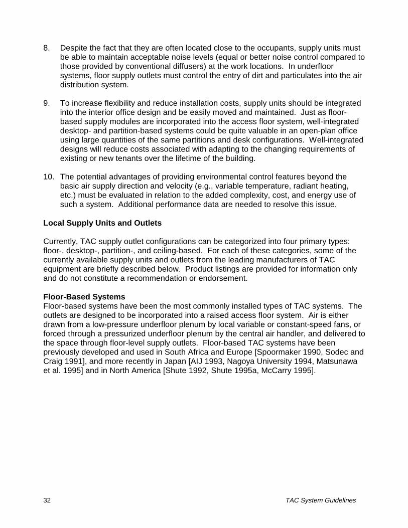
36 TAC System Guidelines
Desktop-Based SystemsA variety of desktop supply outlets have been used and are available, including desktoplevel grills at the back of the desk surface [Barker et al. 1987, Argon 1994], free-standingdirectable supply nozzles at the back of the work surface [Sodec 1984, Arens et al. 1991,Bauman et al. 1993], and a linear grill at the desk’s front edge directly facing the seatedoccupant [Argon 1994, Wyon 1995]. In all systems, conditioned air must be delivered tothe supply outlet through ducts that are adjacent to the desk or incorporated into the deskdesign.
• Personal Environmental Module (PEM) (Figure 8), available from Johnson Controls,Inc., 507 E. Michigan Street, Milwaukee, WI 53202; telephone: 414-274-4000.
This desktop-based system has attracted a good deal of interest and research attention.In this system, each unit uses a self-powered mixing box that is hung in the back orcorner of the knee space of the desk and connected by flexible duct to two supplynozzles on top of the desk. The nozzles provide free jet air flow characteristics. Themixing box uses a small variable-speed fan to pull supply air from either a slightlypressurized underfloor plenum or from flexible ducts in the office partitions suppliedfrom the ceiling. The PEM operates ideally at a supply static pressure of 12-25 Pa(0.05-0.1 in. H2O). At these pressures the PEM can supply a total of 6-70 L/s (12-150cfm) through its two nozzles. Recirculated air is also drawn from the knee spacethrough a mechanical prefilter. Both primary supply air and recirculated room air aredrawn through an electrostatic air filter. The PEM has a desktop control
Figure 8. Personal Environmental Module (courtesy of Johnson Controls)

TAC System Guidelines 37
panel containing adjustable sliders that allow the occupant to control the speed of theair emerging from the nozzles, its temperature, the temperature of a 200-Watt radiantheating panel located in the knee space, the dimming of the occupant’s task light, anda white noise generator for acoustical masking. The control panel also contains aninfrared occupancy sensor that shuts the PEM off when the workstation has beenunoccupied for a few minutes. The results of laboratory and field measurements aredescribed by Arens et al. (1991), Bauman et al. (1993), Bauman and McClintock(1993), and Bauman and Akimoto (1996). Whole-building energy simulations arepresented by Bauman et al. (1994).
• Desk Air Terminal (DAT); available from Argon Corporation, 5020 Tamiami Trail North,Suite 200, Naples, FL 33940; telephone: 941-643-7766.
Argon describes several different supply outlet configurations. The DAT draws supply airfrom an underfloor plenum through a fan-powered access floor panel. A constantvolume (70 L/s [150 cfm)]) of air (under the control of a room thermostat) is deliveredthrough grills out the back of the DAT (away from the occupant) to handle ambientspace loads. Using damper control, the occupant can divert a portion of the supply airout through adjustable grills towards the front of the desk to satisfy their personalcomfort preferences.
• Habistat®; available from Interface Architectural Resources, 100 Chastain CenterBlvd., Suite 165, Kennesaw, GA 30144; telephone: 770-423-1723.
The Habistat® diffuser is a desk-mounted supply nozzle, similar in size to the JohnsonControls PEM. In combination with a fan unit mounted under the desk, it provides upto 28 L/s (60 cfm) of heating or cooling supply air above the desktop and 2 L/s (5 cfm)below the desktop. Optional models also contain a task light, electrostatic filter, anddirect connection to the underfloor supply air plenum (through an Aerlo® unit).
• Climadesk (Figure 9); available from Mikroklimat Sweden AB, Ranovagen 35, S-161 51Bromma, Sweden; telephone: 46-8-26-60-16.
The Climadesk consists of a panel attached to the underside of a conventional desk, andconnected by a flexible duct to a portable filter unit placed next to the desk. Airflowfrom two adjustable outlets at the front edge of the desk are used to condition theoccupant’s local work space. One of the supply outlets delivers supply air directlyupward into the occupant’s breathing zone. The other delivers air toward theoccupant’s body for cooling purposes. The maximum airflow from the Climadesk isonly 7 L/s (15 cfm) because the air is concentrated directly on the occupant. Heatingof the lower part of the body can be provided by a controllable radiant heating panelunder the desk. Manikin experiments found that the temperature experienced by theoccupant can be controlled using Climadesk over the range from 4°C (7°F) below to2°C (3.5°F) above room temperature [Wyon 1995].
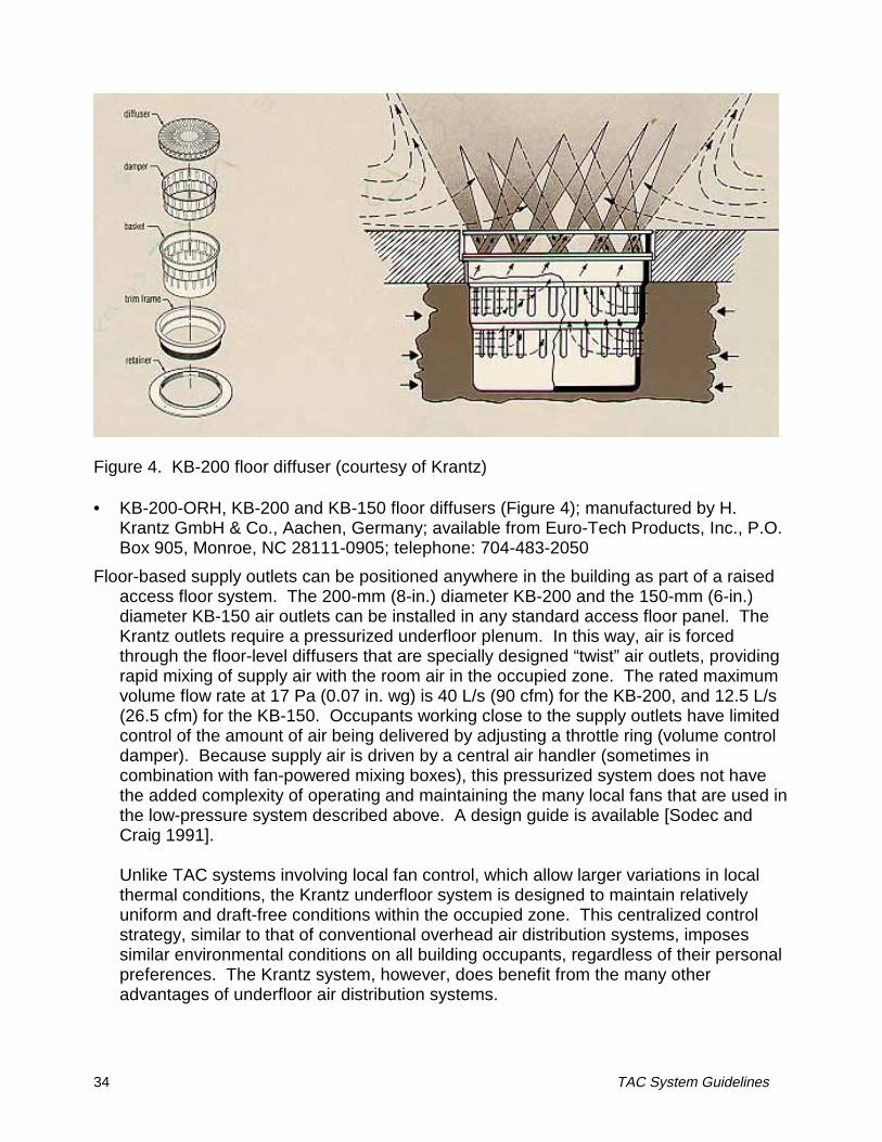
38 TAC System Guidelines
Figure 9. Climadesk (courtesy of Mikroklimat Sweden AB)
Partition-Based SystemsIn recent years, partition-based TAC systems have been introduced for applications inopen-plan office buildings where partitioned workstations are commonly employed. Inthese systems, air is delivered through passageways that are integrated into the partitiondesign to controllable supply grills that may be located just above desk level or just belowthe top of the panel (for personal comfort control), or to outlets on top of the partitions (forambient environmental control). Several of these systems installed in Japanese buildingsare described by SHASE (1991). Partition- and desktop-based systems are mostconveniently combined with underfloor air distribution, but it is possible to feed primary airfrom a ducted ceiling-based system down vertical columns to the partitions and furniture.
Matsunawa et al. (1995) describe an installation in which a combination of floor supplyoutlets and partition-based outlets are used with an underfloor air distribution system. Inthis system configuration, (1) advanced floor outlets may be used (Figure 10a), (2)partitions can be used to exhaust local heat loads (e.g., larger computers) by drawing thewarm air into the partition below the desk and discharging it out through openings on topof the partition (Figure 10b), and (3) partitions may be “plugged in” to floor outlet locations,providing supply air to the occupant from grills above the desk height (Figure 10c).
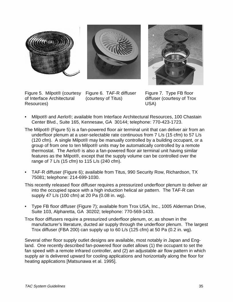
TAC System Guidelines 39
Figure 10. Underfloor air distributionsystem with (A) advancedfloor outlets, (B) heatexhaust partition, and (C)partition-based personalHVAC system [Matsunawaet al. 1995].
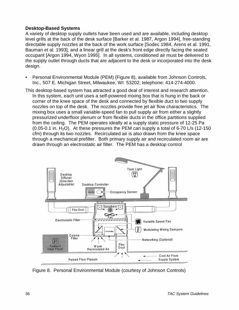
40 TAC System Guidelines
Figure 11. Panel Air Terminal (courtesy of Argon Corporation)
• Panel Air Terminal (PAT) (see Figure 11); available from Argon Corporation, 5020Tamiami Trail North, Suite 200, Naples, FL 33940; telephone: 941-643-7766.In this recently introduced partition-based system, the volume of underfloor supply airis controlled based on a room thermostat. Air is supplied from the underfloor plenumthrough a fan-powered floor panel with a boot connection to the air flow partition. Thissupply air passes up through and out the top of the partitions to ensure that the totalbuilding loads are met. Office workers can divert (using a damper) a portion of thissupply air out grills in the partitions to control their local environment, but the totalvolume delivered to the space remains under the control of the thermostat. Analternative approach is to use a constant volume, variable temperature control strategybased on thermostatic control (space or return temperature), thus ensuring thatminimum outdoor air ventilation requirements are met [Argon 1994].
For information on other partition-based systems, see section on Japanese Manufacturersof TAC Equipment.
Ceiling-Based SystemsLargely in response to the needs of TAC retrofit applications to conventional ceiling-basedair distribution systems, several ceiling-mounted supply outlets have been introduced.These have generally resembled a large ducted adjustable jet nozzle (a large version ofsupply nozzles commonly found in airlines) that injects the air downward at a high enoughvelocity to reach the occupant’s level. In comparison to other TAC system designs,ceiling-based outlets are easier to install during renovation of spaces without raisedaccess floors and with limited floor-to-floor height. However, due to the distance between
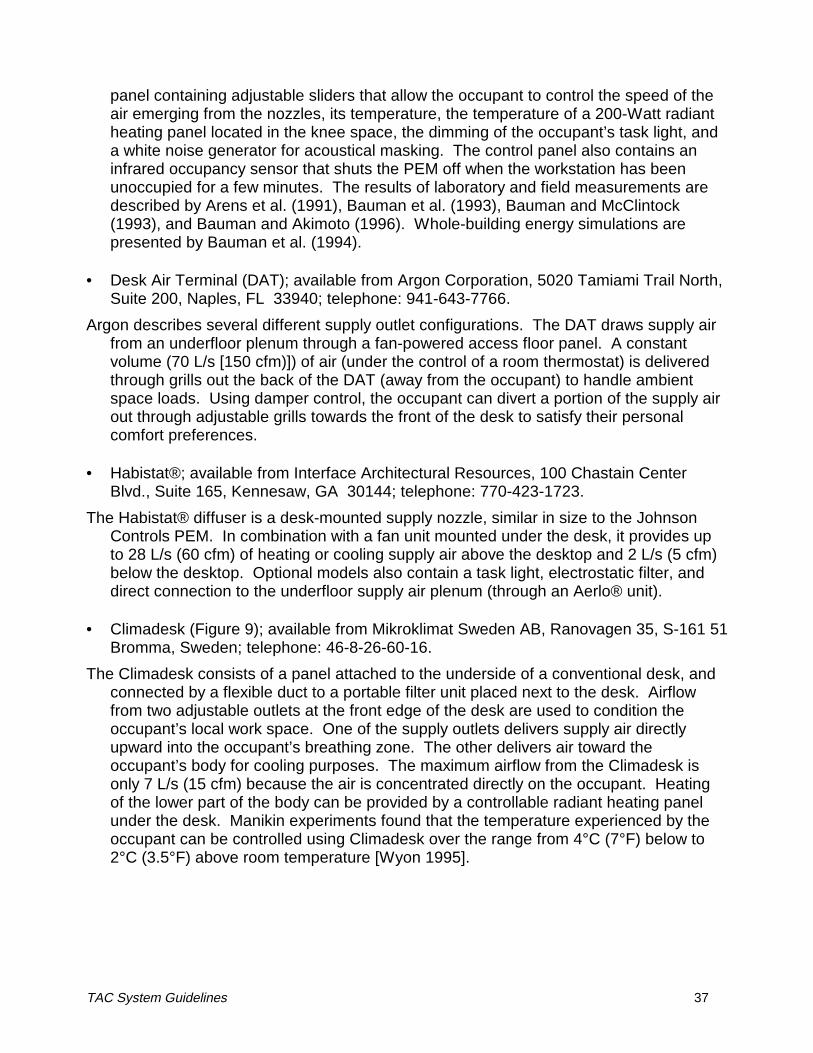
TAC System Guidelines 41
the supply outlet and building occupant, personal comfort control with ceiling-basedsystems is not as effective as with other TAC systems. A remote controller is essential forthis type of system to be practical. Even so, these systems have been well-received bybuilding occupants in some case studies reported in the literature [Tamblyn 1995].Ceiling-based systems do not achieve the same benefits from the use of underfloor airdistribution and the overall floor-to-ceiling air flow pattern found in many other TACsystems.
• Zero Complaint System (Figure 12); available from Tamblyn Consulting Services, 2Sheppard Avenue E., Suite 200, North York, Ontario M2N 5Y7; telephone: 416-226-6565.
Large nozzles installed above each workstation are connected to the building’s ceiling-based air distribution system through an automatic control damper. Cool supply air isinjected downward into the workstation below each nozzle. Using an infrared remotecontroller, the occupant can control the amount of supply air delivered (up to 80 L/s[170 cfm]), activate an LED readout at ceiling level that shows the actual temperature,and adjust the maximum and minimum control damper openings to calibrate thethermostat with the actual workstation temperature. No local fans are involved. Thedirection of the nozzle can be adjusted over an angle of 15° from vertical, but this mustbe done manually, making it inconvenient for frequent change.
Figure 12. Zero Complaint System (courtesy of Tamblyn Consulting Services)
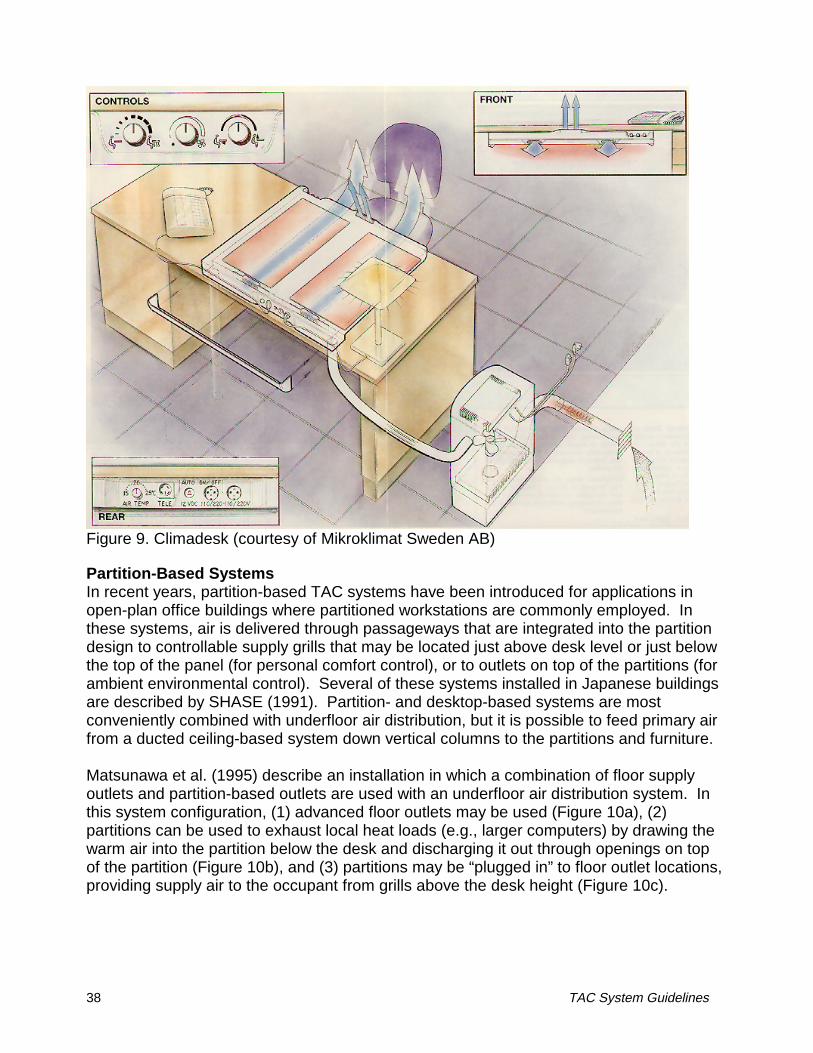
42 TAC System Guidelines
• Individual Air Outlet; available from Air Concepts, Inc., P.O. Box 31177, Tucson, AZ85751-1177; telephone: 520-577-2800.These large nozzles are also installed above each workstation to allow a concentratedcolumn of air to be supplied to occupants or equipment as needed. Airflow direction isadjustable (manually) through ±30° from vertical and through 360° rotation about thecenterline axis. Air supply volume must be controlled by the overhead air distributionsystem. Depending on the size of the outlet (four models are available), 8-100 L/s (17-210 cfm) can be supplied at a pressure of 40 Pa (0.16 in. wg).
Japanese Manufacturers of TAC EquipmentDue to the rapid development of TAC systems in Japan during the past decade, a largenumber of Japanese firms are now manufacturing TAC system products. Floor supplydiffusers are the most widely produced products, but several companies are nowmanufacturing partition-based TAC systems. Associated with underfloor TAC systemdesigns, some Japanese firms are also producing relatively small-sized packaged me-chanical units for air handling, outside air treatment, and control. These units are de-signed with a thin vertical profile and can be serviced from the front, allowing them to becontained within “service system walls.” They are downflow units, thereby deliveringsupply air directly into the underfloor plenum.
Listed below are the leading Japanese manufacturers of TAC equipment. The availabilityand compatibility of these products outside of Japan is not known to the authors.
• Fujita Corporation, 4-6-15, Sendagaya, Shibuya-ku, Tokyo 151, Japan;telephone: 81-3-3402-1911; desk- and partition-based systems.\
• Kokuyo, 6-1-1 Oimazato-minami, Higashinari-ku, Osaka-shi, Osaka 537, Japan;telephone: 81-6-976-1221; partition-based system for tobacco smoke removal.
• Marumitsu, 4-16-11 Kameido, Koto-ku, Tokyo 136, Japan;telephone: 81-3-5626-7511; floor diffusers.
• Matsushita Seiko Co., Ltd., Ventilation and Air Quality Equipment Division, 6-2-61Imafuku-nishi, Joto-ku, Osaka, 536, Japan;telephone: 81-6-930-6931; floor and partition-based diffusers, service system walls.
• Naka Corporation, 1-1-1 Uchisaiwai-cho, Chiyoda-ku, Tokyo 100, Japan;telephone: 81-3-3501-8211; floor diffusers.
• Nittobo, 9-10 Tomizawa-cho, Nihonbashi, Chuo-ku, Tokyo 103, Japan;telephone: 81-3-3669-1413; floor diffusers.
• Obayashi Corporation, 2-2-9 Hongo, Bunkyo-ku, Tokyo 113, Japan;telephone: 81-3-5689-1868; floor diffusers.
• Sinko, 1-4-5 Minamimori-machi, Kita-ku, Osaka-shi, Osaka 530, Japan;telephone: 81-6-367-1811; floor and partition-based diffusers, service system walls.
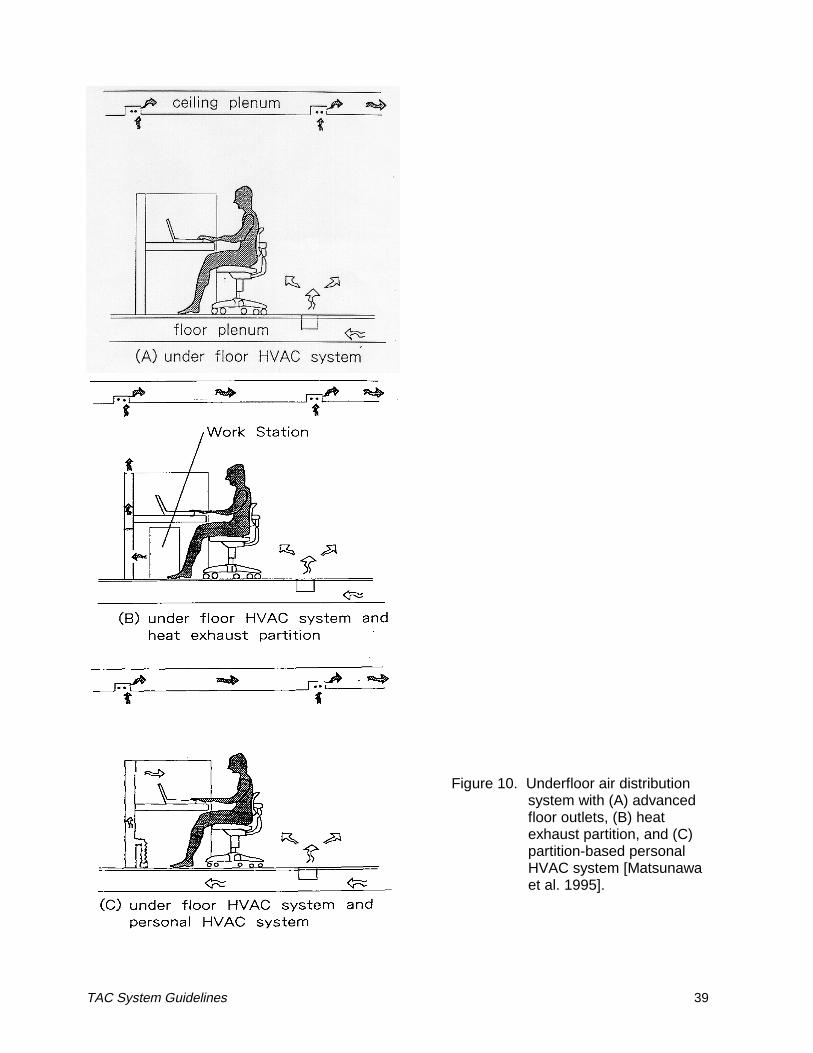
TAC System Guidelines 43
Discussion
A mail survey of U.S. and some international designers, building operators, and HVACmanufacturers was performed to learn about the current state of TAC systems in thebuilding industry [Bauman et al. 1992]. Based on 65 survey responses, the resultsshowed that individual comfort control was viewed as the single most successful attributeof TAC systems. Numerous respondents suggested that individual control should beconsidered as a requirement for new offices, not an option, because of the satisfactionproduced by control. Surveys of operational TAC systems find that building occupantsalso rate individual control highly [Spoormaker 1990, Hedge et al. 1992, Kroner et al.1992, Bauman et al. 1994, Matsunawa et al. 1995].
Another benefit of providing fresh ventilation air in the vicinity of the building occupants isthe potential improvement in ventilation performance and indoor air quality in the occupiedzone. The increased air motion in the occupied zone can lead to the perception by theoccupants that ventilation is adequate. In a related survey, Hedge et al. (1992) havefound that the inability of occupants to control environmental conditions is one of thesalient factors in reports of Sick Building Syndrome (SBS) symptoms, although there is nodirect empirical evidence to support this.
In our laboratory experiments of TAMs and PEMs, we have seen that both systems can becontrolled to provide a wide range of thermal comfort conditions in the local workstationenvironment. In addition, when the supply air jets containing 100% outside air aredirected toward the breathing level at a high enough volume, improved ventilation effec-tiveness can be achieved compared to the case of perfectly mixed air in the office space[Faulkner et al. 1993]. The measured benefit would be smaller in more practical situationsin which a substantial amount of return air is recirculated. However, the ventilationeffectiveness of TAC systems will still not be any worse than conventional overheadsystems, and it is quite likely that occupants will perceive an improvement in air movementand air quality due to the localized air supply outlets.
The effectiveness of local supply units to control comfort will vary depending on the po-sition of the supply outlets in relation to the occupant. Desktop- and partition-based TACunits direct air toward the front and sides of an office worker, typically at desk-level heightsand above. Much like the air-conditioning and heating system on the dashboard of a car,this configuration provides quick and efficient response to occupant control. Floor-basedTAC units typically deliver air from the side and slightly behind the office worker, with thepotential to direct air onto the occupant’s legs and ankles, so this configuration issomewhat less effective for individual comfort control.
A perceived disadvantage of supplying air close to the building occupants is the increasedrisk of draft discomfort. This is one of the main reasons why some engineers refuse tospecify such a system. This risk can be largely eliminated by giving occupants control oftheir local supply unit (they can change the direction or turn the airflow down or off if it istoo drafty) and by positioning uncontrolled units sufficiently far from long-term use areas inthe office. Alternatively, by using a floor diffuser design that promotes rapid mixing with
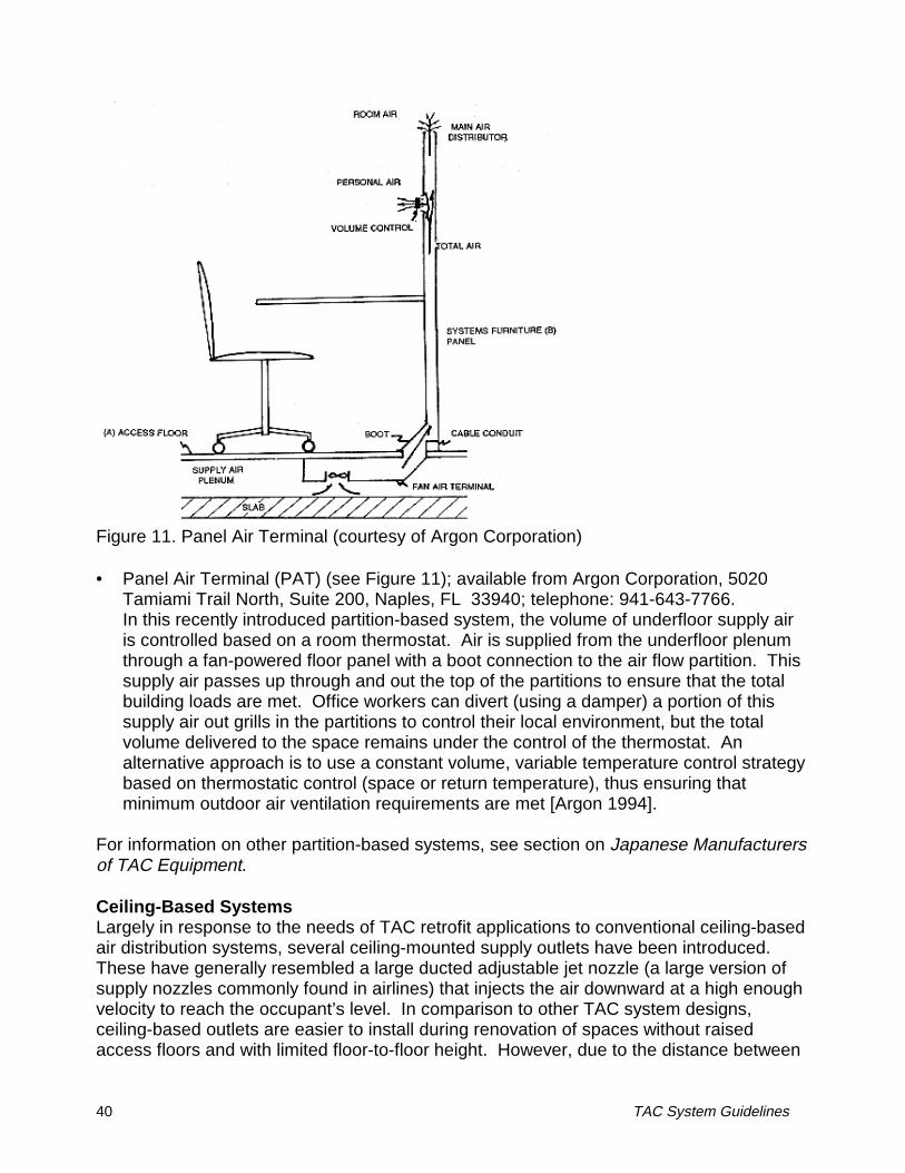
44 TAC System Guidelines
the room air, such as the Krantz system, the risk of draft discomfort may be reduced,except within close proximity to the supply outlets.
At maximum air supply rates both the PEM and TAM have the ability to significantlyovercool the local environment. While future optimized designs of these and other TACsystems may prescribe reduced peak flow rates, it is important for the supply units toretain some capacity to respond to rare events when rapid cooling is required. Thepenalty for not being able to satisfy these peak occupant demands can be long-lasting.During our study of ten San Francisco Bay area office buildings [Schiller et al. 1988], wefound evidence that office workers remembered extreme conditions when the HVACsystem failed to maintain comfort (typically a hot week during the summer) quite clearlyand retained a strong negative image of the building system for several months or longer.
Other Task/Ambient Conditioning Products
Because of the significant advantages of using underfloor air distribution with TAC sys-tems, the selection of a raised access floor system is an important consideration. Raisedaccess flooring provides a multiple-use service plenum, serving the distribution needs forpower, communication, and HVAC operation (air and water). In modern offices wherealmost all workstations contain a computer or some other electrical device, cablemanagement has become an increasingly important issue. During a building’s lifetime,open-plan offices in particular are often reconfigured (this “churn rate” is estimated to beas high as 30% annually) to accommodate changing tenant needs. For these and otherreasons, raised access floors offer advantages and flexibility over other cablemanagement systems. Access floors have been redesigned to be more compatible withoffice applications. Floor panels are less expensive, lighter weight, carpeted, and can bespecially installed to dampen sounds and provide a solid feel underfoot. Although costinghigher ($4 to $6/ft2) than other cable management options, when combined with underfloorair distribution, the economics quickly improve. In new construction, there is the potentialfor reduced floor-to-floor heights. Because of the increased space available below thefloor for air supply in comparison to a conventional ducted ceiling-based system, it ispossible for the overall height of service plenums (underfloor plenum for air supply andmost building services plus a smaller ceiling plenum for air return, electric lighting, and firesprinklers) to be reduced. Some designs may allow the ceiling plenum to be completelyeliminated (for example, see McCarry 1995). For additional discussion of many of theseissues, see Ellison and Ramsey (1989).
The distributed, workstation-based, configuration of TAC systems makes them well-suitedfor control applications using occupancy sensors. Occupancy sensors can be used to turnoff fan-powered local supply outlets whenever the workstation or local zone is unoccupied.This can be an important energy-saving feature considering the amount of time that officeworkers are typically away from their workstations (by some estimates, open-plan officeworkstations in the United States are only occupied on average 50% of the time).Additional energy savings can be realized by putting task lighting and other workstationequipment under occupancy sensor control.

TAC System Guidelines 45
CONTROLS AND OPERATION
Recommendations
1. Local supply outlet temperatures should be maintained above 17°C to 18°C (63°F to64°F) to avoid uncomfortably cool conditions for the nearby occupant. Furthermore, itis preferable to also maintain the air temperature in the underfloor plenum at no lowerthan this same temperature to prevent cold floors. As described earlier, when coolerprimary supply air is introduced directly into the underfloor plenum, it is very importantto ensure that mixing with recirculated air entering the plenum takes place quickly andthoroughly.
2. Due to the importance of individual controls, they should be well designed andconvenient to use. While most floor supply units currently on the market are basedon manual control (requiring the user to bend down to floor level) it may be advisableto incorporate remote desktop controls to operate the floor units; one such remote-controlled floor unit is described by Matsunawa et al. (1995). It is also advisable toallow switching between local (individual) control and automatic (thermostatic) controlas needed.
3. Building operators and occupants who have access to local supply units should beproperly trained to allow the operation and control of the TAC system to be optimized.
4. Occupancy sensors provide an effective means of automatically controlling theamount of energy used by the decentralized network of fan-powered TAC supplyunits. Occupancy sensor performance should be optimized for each application. Forexample, in partitioned open plan offices, occupancy sensors should be shielded fromactivation by office workers walking past the workstations. A filter, time-delay, orpersonal identification strategy may also be used to prevent the sensor fromresponding to quick visits to an unoccupied workstation.
5. Control strategies for the building's central mechanical system should be wellcoordinated with the local control units. For example, since most TAC systems areused for cooling applications, if the general office space is overcooled by the ambientair distribution system control strategy, the cool air provided by local supply units willbe unwanted by the occupants. By allowing the overall space temperature to rise,local cooling can then be used as needed to satisfy individual comfort preferences.
6. TAC system configurations using fan-powered supply outlets provide a convenientmeans of allowing direct occupant feedback to improve overall system operation. Bymonitoring fan speed settings, adjustments can be made to the setpoints for primarysupply air temperature, ambient space temperature, and central supply air volume.For example, when a large enough percentage of occupants in the same zone of thebuilding select low fan speeds, indicating that they are too cool, the primary air supplytemperature to that zone can be raised. With floor supply outlets, this strategy canhelp to prevent excessively cool air pooling across the floor, causing potential draft
46 TAC System Guidelines
discomfort [Matsunawa et al. 1995].
7. The building’s control system can be configured to allow small-sized control zones assmall as individual workstations or areas around a single supply diffuser. These smallzones can be controlled based on feedback provided by the occupant’s use/control ofthe local fan-powered supply diffuser, or by a well-placed thermostat. A computer-based control system can also allow these small control zones to be easily combinedand reconfigured as needed [Matsunawa et al. 1995].
8. In comparison to TAC system designs using fan-powered supply outlets, pressurizedunderfloor air distribution systems with floor supply grills tend to provide a moreuniform distribution of temperature and air movement throughout the space, but lesscapability for individual occupant control. Control strategies for these pressurizedsystems will therefore be closer to conventional approaches that seek to controlconditions in a multi-occupant zone based on a single wall thermostat.
9. In underfloor TAC systems, due to the thermal stability created by the large amount ofthermal storage in the concrete structural slab, predictive control strategies have beenused to estimate the following day’s supply air temperature based on the currentday’s average space temperature. One suggested strategy was to raise tomorrow’ssupply air temperature by 0.6°C (1°F) when the space temperature did not exceed21.7°C (71°F) today, and lower tomorrow’s supply air temperature by 0.6°C (1°F)when the space temperature exceeded 23.9°C (75°F) today [McGregor 1996].
10. With low-pressure underfloor air distribution systems, special methods may beneeded to measure system air flow and to control the VAV operation of the central airhandler. In some cases, it may be preferable to control the operation with small-sizedfloor-by-floor air handling units compared to VAV operation with a larger central AHU.
11. More research is needed to improve overall TAC system performance (e.g., optimizefan speed and temperature setpoints) through methods of control feedback fromindividual TAC units to the central control system. Research is also needed toimprove our understanding of what are the preferred characteristics of individuallycontrolled work environments. Finally, improved engineering guidelines are neededto describe how to effectively utilize the underfloor thermal storage capabilities in TACsystem designs.
Discussion
As stated earlier, our industry survey found that occupant comfort as provided byindividual control was viewed as the most successful performance attribute of TACsystems [Bauman et al. 1992]. Building occupants are known to place a high value onhaving some amount of control over their environment. Because of this, it is believed thatthey will be more tolerant of fluctuating thermal conditions that could reduce costs andenergy use. The provision of individual comfort control has the potential to provide certainadvantages for TAC systems over other air distribution system designs.
TAC System Guidelines 47
While it is well recognized that building occupants prefer individual control, the extent towhich they actually use the local controls, once made available to them, can be surprising.One field survey of several buildings with operational TAC systems found that only 10% ofthe occupants made adjustments to their controls on a daily basis and one third neverused the controls at all [Hedge et al. 1992]. Two recent field studies have similarly foundrather limited use of the local controls by the occupants [Bauman et al. 1993, Bauman etal. 1994]. There are a number of possible reasons for this seemingly limited use of theoccupant controls. (1) If the ambient space is well conditioned, there may be little need forindividuals to fine-tune their local environment. (2) The design of the controls themselvesmay not be optimized, making their use inconvenient. (3) There may be an upper limit tothe role that people prefer to play in the active control of their environment. In otherwords, there may be a penalty associated with actually having to "do something" tomaintain comfort conditions, which could actually increase occupant dissatisfaction[Paciuk (1989)]. (4) Only an occasional adjustment is required because individualpreferences are relatively stable. (5) The sense of control may be more important increating comfort than the actual environmental conditions.
The occupant controls are compared briefly below for four TAC systems discussed above.
1. The floor-based Task Air Module (TAM) can be controlled by reaching down to floorlevel and adjusting flow direction or fan speed. While these manual controls aresimple to perform and quite reliable, it can be awkward for some office workers toreach down to the TAM. The thumb-wheel knob that controls fan speed is difficult tooperate and it is not immediately obvious which direction to turn the knob in order toget the desired effect.
2. The desktop-based Personal Environmental Module (PEM) features a more advanceduser interface with the multi-function control panel located conveniently on the desk.The control panel is easy to operate and also contains an occupancy sensor, allowingthe local unit to be turned off when the workstation is unoccupied.
3. The Krantz underfloor air supply system is generally not configured to allow occupantcontrol, relying instead on the mixing from its diffusers to maintain acceptable thermalconditions in the occupied zone. A throttle ring can, however, be installed in the flooroutlets that, when rotated, controls the air flow volume, although not the direction.
4. The Japanese remote-controlled fan-powered floor supply unit described byMatsunawa et al. (1995) allows individuals to conveniently control the fan speed(supply volume) of the floor supply unit. The unit also displays current supply volumeto provide immediate feedback to the occupant.
As more task conditioning supply units are developed, the best control characteristics canbe utilized. The most effective design solution may be a combination of different supplyunits and control strategies.
Beyond the development of practical controls for individual TAC supply units, the successof the overall building HVAC system is critically dependent on control issues. Typically,control problems cause a majority of system failures and difficulties. In a TAC system with
48 TAC System Guidelines
occupant control, the design engineer has the responsibility of maintaining control of theoverall system performance while "giving up" a certain amount of control tounsophisticated users, a situation that many would choose to avoid. On the other hand,by allowing individual control, the system’s ability to provide comfort is enhanced throughthe use of multiple "human comfort" thermostats. While a normal thermostat respondsonly to temperature, the human body is a complex integrating instrument, responding tothe combined effects of temperature, air movement, radiation, humidity, activity, andclothing level.
It is desirable to provide clear operating instructions for the TAC units to the occupants aswell as more advanced training to the building operator. For example, some designspecifications encourage individuals to leave their local units on at some intermediate levelwhen they are away from their desk, because the overall system performance depends onthe delivery of an adequate amount of air through the TAC supply units.
More advanced controls, such as those included with the desktop PEM, can perform manyof these same functions automatically without relying on occupant behavior. Even whenthe local fan unit is turned off, the main supply line damper is not allowed to closecompletely and the ducted primary air supply is maintained at a slight positive pressure toensure that fresh ventilation air is provided at all times. The occupancy sensor alsoprovides important energy savings as discussed further below in Energy Use. During ourfield tests with the PEM units in PG&E’s Advanced Office Systems Testbed Project, wenoted a few improvements that could be made to the PEM control performance [Baumanand McClintock 1993]:
1. The positioning of the occupancy sensor is critical. If it is in direct view of theentrance to the workstation, a PEM in an unoccupied workstation can be turned onevery time someone walks past. In addition to being properly shielded against walk-by turn-ons, the occupancy sensor should also be adjusted (using a filter, time delay,or personal identification) to ignore quick workstation visits, such as a co-workerdropping off some papers in an empty workstation.
2. When the workstation is unoccupied it may be desirable to allow the PEM air supplyto completely shut off, provided there is adequate ventilation air being supplied atother locations in the space. If, for example, the PEM units were combined in anoffice with additional floor-based diffusers that could not be turned off by occupants,these floor diffusers could take care of minimum ventilation rates when large numbersof PEM units were turned off.
3. When an occupant calls for more air flow from the PEM, an improved strategy may beto open the return air damper (pulling air from the kneespace under the desk),thereby providing the requested air flow without having to increase the delivery ofprimary air.
4. Improvements should be made in the PEM task light dimming control to allowcompatibility with a wider range of desk lights now available on the market.
TAC System Guidelines 49
The distributed and decentralized configuration of TAC systems allows improved efficiencyin handling part-load conditions that are either localized or occur during off-hours. Forexample, the load can be met by only activating the necessary fan coil units and the localsupply outlets in the affected occupied zone.
In a TAC system involving separate task and ambient subsystems, the design engineerwill have to consider several system integration and control issues including the following:(1) What percentage of the building space conditioning load will the task system handle incombination with other more conventional building systems? (2) How does the use of thetask system affect supply air flow rates and setpoint temperatures? (3) How does the tasksystem affect fan energy use of the main system? (4) How is the control and operation ofthe main air handling unit affected by the task system?
Imagawa and Mima (1991) describe one example of a Japanese installation involving aceiling-based air distribution system for ventilation and ambient space control combinedwith a separate partition-based task conditioning system that provides cooling and heatingwith recirculated air. The control sequence is based on the ambient space temperature(Tamb). When Tamb > 24.5°C (76°F), cooler air is supplied to the task system. When Tamb
> 26°C (79°F), the ambient system provides additional cooling. When Tamb < 23.5°C(74°F), task heating is provided. When Tamb < 22°C (71.5°F), ambient heating is alsoprovided. The ambient setpoint is also adjusted based on the percentage of fan-poweredtask units in use.
Supply volume control of the central VAV air handler requires a different approach withlow-pressure underfloor air distribution systems. As previously described, due to theextremely small pressure differentials between the supply plenum and the space,traditional velocity sensors do not provide accurate measurements. An ingenious controlstrategy proposed by Shute (1992) uses a temperature sensor in the vertical inductionshaft connecting the return air at ceiling level to the underfloor plenum. Under normaloperating conditions, the floor supply units will be delivering more air to the space than isprovided by the central system. In this case, the temperature sensor will measure normalroom return temperatures as the air is drawn down the induction shaft to mix withincoming primary air. If, however, the temperature in the induction shaft decreasesrapidly, it indicates that the demand for air supply through the floor supply modules hasbeen reduced (i.e., fan units have been turned down or off), resulting in theoverpressurization of the underfloor plenum. The central air handler can then be throttleddown until the reversal in flow direction through the induction shaft is eliminated.
Future research related to the control and operation of TAC systems is needed to addressthe following issues:
• Optimization of overall system performance. Due to the limited amount of performancedata from operational TAC systems, more field studies are needed to provideadditional information on successful operation and control strategies, and occupantresponse to the TAC system,
• Human thermal preferences for individually controlled local environments. Humansubject testing in a laboratory setting is needed to more accurately define thermal
50 TAC System Guidelines
preferences and the limits of thermal acceptability when the subject has some amountof individual control over the local environment, in terms of the following: (1) What isthe relative importance to the subjects of the actual local thermal conditions vs. thesense of having individual control over these local conditions? (2) To what extent willsubjects tolerate a warmer ambient environment with individual control of local cooling?(3) To what limits will subjects accept asymmetric thermal conditions on their bodyproduced by local air supply and radiant heaters under their personal control? (4) Forlocally controlled air supply, what are the preferred source locations and configurations,supply directions, air velocities, and air flow patterns (for example, see Fountain 1993and Fountain et al. 1994)? (5) To what extent will subjects tolerate a thermalenvironment that is more variable vs. constant over time?
• Thermal performance of underfloor supply air plenums. Experimental and analyticalstudies are needed to develop improved engineering guidelines for designing andoperating a TAC system using an effective thermal storage strategy in the underfloorconcrete structural slab.
• TAC system operation in alternative officing installations. Due to rising corporateinterest in alternative officing environments, field studies are needed to investigateeffective ways to control and operate TAC systems in these highly flexible officeconfigurations.

TAC System Guidelines 51
ENERGY USE
Recommendations
1. With an underfloor air distribution system and the right climatic conditions, takeadvantage of the extended hours of operation of an outside-air economizer allowed bythe higher supply air temperatures. Due to humidity problems in many U.S. climates,however, outside air temperatures above 18°C (65°F) should not be used.
2. Use a 24-hour thermal storage strategy in the exposed structural mass of the floorplenum to reduce peak cooling (and heating) loads, reduce electric utility peak demandcharges, and downsize the cooling equipment. Nighttime precooling of the thermalmass can also take advantage of extended economizer operation (under suitableoutside air conditions).
3. Space temperature control within the building should be adjusted to realize potentiallyavailable cooling energy savings. (1) Due to the increased air movement andcontrollability provided by the local supply units, maintain higher average spacetemperatures and allow greater temperature variations (slow drifts) to occur inresponse to the outside daily cycle. (2) Allow properly controlled thermal stratificationto occur using an overall upward flow of air in the space. (3) Use zoning controlstrategies in which temperature setpoints can be relaxed in less critical building zones,while occupied areas can be well conditioned by the local supply units, if desired by thebuilding occupants.
4. Occupancy sensors should be used to turn off fan-powered local supply units when notin use, provided minimum ventilation rates are maintained within the space. This willminimize the load from local fans and other components.
5. To the extent possible, the central fan should be downsized by taking advantage ofreduced static pressures available in an underfloor plenum supply configuration, byminimizing the amount of air delivered by the central fan (e.g., supply only minimumrequired outside air quantity), and relying on the local fan units to provide thenecessary air exchange in the space.
6. Water-based fan coil units and heat pumps may be the most energy efficientapproaches to handling the extreme cooling and heating loads that occur onlyoccasionally and at specific locations (e.g., perimeter zones) in the building.
7. The efficiency of local fan motors should be improved and incorporated into futuredesigns of local supply units.
Discussion
There are many factors that can affect the energy performance of TAC systems.Responses to our industry survey [Bauman et al. 1992] indicated that opinions were fairlyevenly split regarding the energy use of a TAC system in comparison to a conventional
52 TAC System Guidelines
system; 32% stated that energy use would be somewhat or greatly improved, 28% roughlyequivalent, and 22% somewhat worse. It was also felt that energy performance would beapplication-specific, further evidence of the uncertainty associated with trying to generalizeabout overall energy use. Not surprisingly, energy use was identified as one of the topthree issues concerning TAC systems that would warrant further research. In theliterature, only a few studies of energy use of TAC systems are reported. Two earliercomputer modeling studies concluded that installations may use either more or lessenergy compared to a conventional air distribution system depending primarily onoperating strategies [Heinemeier et al. 1991, Seem and Braun 1992].
In a more recent study, annual building energy simulations using DOE-2 investigated theenergy performance of a prototypical office building in two California climates, Fresno andSan Jose [Bauman et al. 1994]. The simulations compared three different TAC systemconfigurations versus a base case building consisting of a reasonably efficient standardoverhead air distribution system with an air-side economizer. The operation and controlstrategies that proved to have the greatest energy impact were (1) use of an air-sideeconomizer, (2) increased throttling range (up to 4°C [7°F]) for space temperature controlallowed by the individual controllability of the TAC systems, (3) increased stratification (upto 2.5°C [4.5°F]) in the space produced by the floor-to-ceiling air distribution of the TACsystems, and (4) nighttime precooling of the building thermal mass in the underfloorplenum by fan-driven ventilation. The simulation results showed that, in comparison to thebase case, a desktop-based TAC system with occupancy sensor control and the first threeof the above strategies in a San Jose office building could save annually as much as 18%of the cooling energy, 18% of the distribution (fans and pumps ) energy, 10% of the totalelectricity, and 9% of the total electricity cost. When nighttime ventilation was added, thecooling energy savings increased to 23%, but distribution energy increased to 2% abovethe base case due to the nighttime operation of the fans. In this latter case, although totalelectricity use was slightly higher (9% lower than the base case), total electricity costsremained the same (9% below base case) because of the further reduction in peakdemand provided by the nighttime ventilation strategy.
Despite the above described potential energy savings, as with any new technology it ispossible to operate a TAC system in an energy inefficient manner. An example of this isdescribed by Bauman et al. 1994, who conducted a field study of a floor-based TACsystem in an engineering office building. The system being studied consisted of fan-powered floor supply modules with the underfloor air supply plenum being served by avariable-air-volume (VAV) central air handling unit (AHU). Although the recommendedoperating procedures called for the underfloor plenum pressure to be maintained at a zeroor slightly negative pressure with respect to the occupied space, the building operatorswere unable to control the AHU at these low pressures, and instead were maintaining aconstant higher pressure across the VAV box serving the underfloor plenum. As a result,the underfloor plenum was overpressurized, leading to excessive central fan energy use(estimated to be 10 W/m2 [0.9 W/ft2]), excessive air flow into the space, and overcooledconditions for some occupants. The overcooled conditions had in turn led to a situation inwhich many occupants did not want any airflow from their floor supply modules, and onlyabout one/third of these floor supply units were in use. It was estimated that by reducingthe central AHU air supply volume, improving the integration of the AHU and floor supply

TAC System Guidelines 53
modules, and turning fans down or off during low-load periods, annual total fan energy usecould be reduced by more than 60%.
At first glance at the energy performance issue, the major disadvantages of occupant-controlled TAC systems compared to conventional systems are: (1) with fan-powered localsupply units, the operation of many small individual fans; and (2) the fact that individualsare allowed to control these supply units to optimize their personal thermal comfort withoutregard for the energy performance of the overall system. The first is the result of switchingfrom a more conventional centralized design to a decentralized design. The secondinvolves the integration of the TAC system with the total HVAC system. Both of thesetopics are discussed briefly below.
The small fans contained in the controllable TAC supply units are less efficient than thelarge fans used in a centrally-controlled system. In more complex TAC units, such as theJohnson Controls PEM, additional electrical energy is consumed by the electronic controlsand the radiant heating panel (when in use). On the other hand, the Krantz underfloor airsupply system does not use fan-powered supply units and in this way resembles acentrally-controlled system. Central fan energy use will be correspondingly higher in thiscase.
The fan efficiency of the fan-powered floor-based supply module (e.g., Tate’s TAM) iscurrently on par with that of relatively efficient ceiling-based parallel fan-powered mixingboxes (FPMB) (0.54 W/l s-1 [0.27 W/cfm]). However, unless series FPMBs are installed ina conventional system, FPMBs do not need to operate continuously or as often as a TACsupply unit at an occupied workspace. Normally, parallel FPMBs are operated only whenneeded (e.g., on a call for heating in perimeter zones of the building). Clearly, an effectivestrategy will be to minimize to the extent possible the local fan load in a TAC system.
In an underfloor air distribution system, significant reductions in central fan static pressurecan be realized, thereby conserving central fan energy in comparison to a ducted system.In addition, if a large amount of return air from the room is drawn into the sub-floor plenumto be mixed with incoming primary air, the low resistance and short path length requiredfor this process can translate into savings in fan energy compared to a conventionalsystem that recirculates air all the way back to the central air handling unit. Spoormaker(1990), who has successfully installed numerous TAC systems using fan-powered floorsupply modules, claims to be able to meet the cooling load in the interior zone of an officebuilding with a total fan load (central plus local) that is 56% of the required central fan loadof a comparable all-air ceiling distribution system. In his calculations, although the localfan load is approximately 4 W/m2 (0.4 W/ft2), the central fan load for the TAC system isreduced to 1.5 W/m2 (0.14 W/ft2) by handling only the quantity of outside air required tomaintain minimum ventilation rates.
In terms of the occupant control issue, it can be said that in any situation where buildingoccupants are uncomfortable they will often take matters into their own hands. In abuilding with a centralized air distribution system, these dissatisfied occupants mayoperate desk fans or electric heaters to satisfy their needs. By providing controllablesupply units, a TAC system may in fact provide some improvement over this ratherrandom approach. In addition, by providing occupancy sensors to turn off local units when

54 TAC System Guidelines
they are not needed, significant reductions in energy use can be obtained for many officeoccupancy patterns. Based on field measurements of the PEM, Bauman et al. (1993)estimated that such an arrangement could save up to 30% of the local fan and lightingenergy used during the course of a typical work day.
As discussed earlier in Controls and Operation, the provision of individual control andincreased air velocities can lead to reductions in equipment costs and energy use forcooling applications, because the occupants will be more tolerant of higher average roomtemperatures and of a greater daily variation in temperature related to the outside diurnalcycle.
Other temperature control strategies with TAC systems can also result in cooling energysavings compared to a conventional system. Thermal stratification produced by anupward movement of air in the space, if properly controlled, can result in cooling energysavings of as much as 15% [Shute 1992]. In this situation, the temperature of the spaceabove the occupied zone can be allowed to increase, as some of the warm air generatedby space heat loads reaches the ceiling-based return location without being completelyneutralized by the incoming supply air.
As previously described in Task/Ambient Conditioning System Design, under the rightclimatic conditions, an underfloor air distribution system allows the implementation of a 24-hour thermal storage strategy using the mass of the building structure exposed to the airflowing through the plenum. By precooling the thermal mass during the nighttime, peakcooling demand can be partially offset during the following day. Spoormaker (1990) hasestimated that such a strategy can reduce peak instantaneous cooling loads in interiorzones of office buildings by as much as 40%. Shute (1995a) estimates that thermalstorage effects are approximately 30% of a typical daily cooling load. This 24-hourthermal storage strategy also extends the hours that an outside-air economizer can beused due to the cooler nighttime temperatures. Under winter conditions, the thermalstorage can also be used to assist nighttime heating, if required, by recovering heat storedin the mass during the previous day’s cooling cycle. Additional research is needed tomore precisely quantify the potential benefits of using thermal storage in the structural slaband to provide guidelines for the design and operation of underfloor air distributionsystems using such a strategy.
TAC System Guidelines 55
DESIGN AND CONSTRUCTION
TAC systems require good coordination between all building trades throughout the designand construction process, particularly if using an underfloor air distribution system. Shute(1995a) provides an excellent list of recommendations for the design and construction ofunderfloor air distribution systems. McCarry (1995) and Blaevoet (1995) also describesome guidelines based on their experiences with underfloor TAC system installation.Shown below is a partial list of recommendations for design and construction.
• It is essential that the implications of the raised access floor be considered early in thedesign process.
• The concrete slab surface must be sealed to reduce dust, and the underfloor plenumand floor panels must be thoroughly cleaned both during installation of the access floorand again before occupancy.
• The height of the access floor and the placement of the 0.6 m x 0.6 m (2 ft x 2 ft)raised floor pedestal grid is critical with respect to locating all underfloor serviceinstallations.
• It is important to lay out underfloor equipment requiring regular maintenance to belocated in accessible areas, such as corridors, not underneath furniture and partitions.
• In partitioned office spaces, offset the partition grid from the floor grid so that partitionsdo not cover joints between floor panels, thereby preventing access to the underfloorplenum on both sides of the partition.
• Consider dead load allowance and seismic bracing of the access floor.
• Determine areas in the building with no access floor and allow for transitions to areaswith access flooring.
• In pressurized underfloor air distribution systems, greater care must be taken duringconstruction to seal the underfloor plenum to prevent uncontrolled air leakage.
• Designers must consider that fan rooms or access for HVAC distribution will berequired at more frequent intervals than with conventional air distribution systems.
• If called for, return air shafts must be designed between the ceiling and the underfloorplenum, usually around columns or other permanent building elements.
• The main structural slab, the traditional working platform, will not be availablecontinuously during construction, and therefore a well-coordinated constructionsequence is necessary (see Shute 1995a).
• In retrofit jobs, special consideration should be given to the installation of TAC supplyunits within a person’s work area. The occupants should be well-informed of theproposed design and placement of the supply outlets and controls, to avoidunnecessarily upsetting them as the result of a perceived thoughtless intrusion intotheir personal workplace.
56 TAC System Guidelines
SYSTEM COSTS
Recommendations
It is recommended that the costs of TAC systems be evaluated over the building’s lifetime,including first costs, maintenance and operating costs, space changeover costs, and thepotential cost savings associated with improved thermal comfort, ventilation effectiveness,and worker productivity. In order to complete such a life-cycle economic analysis, moreresearch is needed to quantify the effects of providing individual control and improvedbuilding environmental quality on worker productivity.
Discussion
As described earlier, the costs associated with installing, operating, and maintaining abuilding’s HVAC system play a critical role in the selection process. The results of arecent survey of industry perspectives on TAC technology demonstrate the importance ofcost considerations to the building industry [Bauman et al. 1992]. This survey found theperceived higher cost of TAC systems to be one of the two top reasons that TACtechnology is not used more widely by the industry today (the other reason is a lack ofinformation and experience). On the other hand, the perceived beneficial features of TACsystems can help to offset the negative impact of increased costs. For example, amajority of the survey respondents felt that occupant comfort (83%), worker productivity(62%), and indoor air quality (54%) were improved for a TAC system compared to aconventional system. Correspondingly, a majority of the survey respondents alsoindicated that equal or higher costs of TAC systems compared to conventional systemsare justified by improved comfort (80%), productivity (68%), and air quality (64%).
First costs for TAC systems utilizing raised access flooring will probably, although notnecessarily, be slightly higher than those for a conventional system. However, the amountof this increase can be minimized and in some cases completely offset by savings ininstallation costs for ductwork and electrical services, as well as from downsizing of somemechanical equipment. Based on previous experience, one design engineer describeshow he can break even in first costs for a pressurized underfloor air distribution systemcompared to a conventional overhead system by using the following rule of thumb: cost ofunderfloor air system (raised access flooring and floor supply outlets) = $8/ft2; cost savingsin ductwork = $6/ft2; cost savings in electrical services = $2/ft2 [Blaevoet 1995]. For TACsystems with individual fan-powered supply units, initial equipment costs are expected tobe somewhat higher than centralized systems or TAC systems without local fan units. Inan economic analysis by York (1993), adding an access floor to a conventional 9,300-m2
(100,000-ft2) building increases its first cost by 2.4%. However, if the underfloor plenum isused for air distribution with fan-powered floor diffusers, the first cost of the building isincreased by only 1.4% over the baseline. As described earlier, another important firstcost consideration in new construction is that underfloor air distribution can lead toreduced floor-to-floor heights.
Since TAC systems still represent a new and unfamiliar technology, a designer may incuradded up-front costs associated with selling the idea of TAC technology to the client and
TAC System Guidelines 57
developing the building design. Utility incentive programs, if available, could help tocompensate designers of energy-efficient TAC systems for any higher first costs duringthe design phase of a project.
Operating costs for TAC systems can be reduced in accordance with the energy-savingstrategies discussed above in Energy Use. With the improved thermal comfort andindividual control provided by TAC systems, occupant complaints requiring response byfacility maintenance staff can be minimized. This can be a significant savings asevidenced by recorded complaint data from the corporate headquarters of the West BendMutual Insurance Company -- a new office building occupied in 1991 in which 370 desktopTAC units were installed. In comparison to the previous headquarters building, hot/coldcalls were reduced from an average of 40 calls per month to only 2 calls per month[Lomonaco 1996]. Other operation and maintenance cost savings that can be achievedwith underfloor air distribution include (1) lower labor costs resulting from working at floorlevel instead of on ladders at ceiling level, and (2) lower air balancing costs due to thesimilar pressure conditions at supply diffuser locations provided by an underfloor airsupply plenum.
Some maintenance costs of underfloor TAC systems may increase in comparison toconventional overhead systems. For example, equipment maintenance costs associatedwith the moving parts and larger number of distributed units may increase for systemsusing fan-powered supply units. Another maintenance issue to consider is the location ofunderfloor mechanical equipment, such as fan-coil units. In buildings with frequentfurniture moves, it is important to maintain free access to the panels above theseunderfloor units. The key items (if present) requiring maintenance include (1) coilcleaning, (2) condensate pan cleaning, (3) fans, and (4) changing filters (a 3-6 monthservice cycle is recommended).
Underfloor TAC systems using raised access flooring provide maximum flexibility andsignificantly lower costs associated with reconfiguring air supply locations and otherbuilding services to adapt to the changing requirements of existing or new tenants over thelifetime of the building, and thus reduce life-cycle costs substantially. This flexibility can beespecially important over the lifetime of buildings having high churn rates. It is estimatedthat approximately one-third of U.S. commercial office spaces get reconfigured each year[York 1993]. Assuming a 30% churn rate, York estimates 5-year life cycle costs for anintelligent building containing an underfloor TAC system and advanced lighting to be 7%lower than that for traditional buildings. York’s analysis reveals the significant operationalcost advantages of such an intelligent building design over traditional buildings -- theannual operational costs alone are estimated to be only 8% of those for the traditionalbuilding. Blaevoet (1995) assumes a 15% churn rate in his life-cycle cost model whichpredicts a 2.7% reduction in 5-year life-cycle costs for a pressurized underfloor TACsystem compared to traditional designs. Shute (1995b) presents actual cost data from acompleted project showing a 5% reduction in 5-year life-cycle costs for a low-pressureunderfloor TAC system with fan-powered floor supply units compared to the estimatedcost if a conventional VAV system had been installed in the same building.
58 TAC System Guidelines
Probably the most attractive feature of TAC systems is the provision of individual controland the potential for individual workers to maintain a high quality work environment of theirchoice. Although it is difficult to quantify, there is a growing belief that actual andperceived improvements in environmental quality can lead to increased worker satisfactionand productivity. The financial implications of improving productivity by even a smallamount have the potential to be very large as salary costs typically make up at least 90%of all costs (including construction, operation, and maintenance) over the lifetime of abuilding. Nationwide, a mere 1% increase in worker productivity would translate into apotential annual cost benefit of $25 billion. In today’s competitive world economy, acompany’s employees make up its most valuable economic assets. Protecting andimproving the productivity of these employees will have a strong influence on futureinvestments. One of the first major studies of productivity used self-assessed jobperformance to conclude that improved thermal comfort and worker satisfaction can leadto increased worker productivity [Brill and Margulis 1984]. Wyon (1996) estimates thateven under the conditions of thermal neutrality with the environment, the provision ofindividual control of local cooling and heating equivalent to ±3°C (5°F) can improve groupwork performance by 3-7%, depending on the nature of the task. This is because theaverage neutral temperature cannot satisfy all occupants, whose individual thermallyneutral points vary substantially. If the room temperature is raised above thermalneutrality, Wyon estimates the performance improvement to be significantly higher. Mostof the currently available fan-powered TAC supply outlets provide individual control of localtemperatures over this same ±3°C range. A recently completed field study of the firstlarge installation of Johnson Controls PEM (desktop) units in a new office building hasconcluded that the PEM system was responsible for a 2.8% increase in worker productivity[Kroner et al. 1992]. In this case, assuming that the average worker salary was $30,000and the cost of each PEM unit was $1,200, the payback period for the PEMs would beonly 1 1/2 years.
Looking to the future, more research is needed to improve our understanding of whatimpact the provision of individual control and improved building environmental quality hason worker productivity. Due to the recognized difficulty in quantifying productivity intoday’s largely knowledge-based work environment, innovative research approaches mustbe devised to address this issue of critical economic significance.
TAC System Guidelines 59
ACKNOWLEDGMENTS
This research was funded by the California Institute for Energy Efficiency (CIEE), aresearch unit of the University of California. Publication of research results does not implyCIEE endorsement of or agreement with these findings, nor that of any CIEE sponsor.We would like to acknowledge the support of Jim Cole, CIEE Director, Karl Brown, CIEETechnical Liaison, and Mark Modera of the Indoor Environment Program, Energy andEnvironment Division, Lawrence Berkeley National Laboratory, who served as the leadinvestigator for this coordinated CIEE multiyear research project.
During the past six years many of our colleagues have made valuable contributions in timeand effort to this project. We would like to acknowledge the enthusiastic technical supportfrom Charlie Huizenga, Charles Benton, Gail Brager, Zhang Hui, and Tengfang Xu of theDepartment of Architecture and Center for Environmental Design Research (CEDR),University of California, Berkeley, and former Ph.D. student researchers, Marc Fountain ofEnvironmental Analytics, Point Richmond, Calif., and Kristin Heinemeier of Honeywell,Minneapolis, Minn. In addition, Zhang Hui produced the fine schematic diagrams of TACsystems. William Fisk, David Faulkner, and Douglas Sullivan from the Indoor EnvironmentProgram, Lawrence Berkeley National Laboratory, made important research contributionsin support of this project. The project was expertly administered by Nora Watanabe andthe friendly CEDR staff, Kimberley Allen and Alice Gates.
We would like to thank Shin-ichi Tanabe of Ochanomizu University, Tokyo, and TakashiAkimoto of Shimizu Corporation, Tokyo, for their technical advice and for providing theinformation on Japanese equipment manufacturers. We would like to express ourappreciation for the contributions of their valuable time and practical expertise to JeffBlaevoet of Guttmann and MacRitchie, San Francisco, Calif.; Hans Levy of ArgonCorporation, Naples, Fla.; Alisdair McGregor of Ove Arup & Partners, San Francisco,Calif.; and Robert Shute of The Mitchell Partnership, Willowdale, Ontario, Canada.Finally, we would like to thank the participants of the Workshop on Task/AmbientConditioning Systems in Commercial Buildings, May 4-5, 1995, San Francisco, Calif., whoimproved the quality of these guidelines through their discussions during the workshopand subsequent reviews of the preliminary draft.
60 TAC System Guidelines
REFERENCES AND ADDITIONAL READING
Architectural Institute of Japan. 1993. Proceedings, Symposium on Floor-Based AirSupply HVAC Systems. Tokyo, October 1 (in Japanese).
Arens, E.A., F. Bauman, L. Johnston, and H. Zhang. 1991. “Testing of localizedventilation systems in a new controlled environment chamber.” Indoor Air, No. 3, pp.263-281.
Arens, E.A., and F.S. Bauman. 1994. “Improving the performance of task conditioningsystems.” Proceedings, International Symposium: Issues on Task-AmbientConditioning. Nagoya University, Nagoya, Japan, 11 January, pp. 77-94.
Arens, E., M. Fountain, T. Xu, K. Miura, H. Zhang, and F. Bauman. 1995. “A study ofoccupant cooling by two types of personally controlled air movement.” Proceedings,Pan Pacific Symposium on Building and Urban Environmental Conditioning in Asia.Nagoya University, Nagoya, Japan, 16-18 March.
Argon Corporation. 1994. “The Argon system.” Naples, FL: Argon Corporation,November.
Arnold, D. 1990. “Raised floor air distribution -- a case study.” ASHRAE Transactions,Vol. 96, Pt. 2.
ASHRAE. In press. ASHRAE Standard 129P, “Standard method of measuring air changeeffectiveness.” Atlanta: American Society of Heating, Refrigerating, and Air-Conditioning Engineers, Inc.
ASHRAE. 1992. ANSI/ASHRAE Standard 55-1992, “Thermal environmental conditionsfor human occupancy.” Atlanta: American Society of Heating, Refrigerating, and Air-Conditioning Engineers, Inc.
ASHRAE. 1990. ANSI/ASHRAE Standard 113-1990, “Method of testing for room airdiffusion.” Atlanta: American Society of Heating, Refrigerating, and Air-ConditioningEngineers, Inc.
ASHRAE. 1989. ANSI/ASHRAE Standard 62-1989, “Ventilation for acceptable indoor airquality.” Atlanta: American Society of Heating, Refrigerating, and Air-ConditioningEngineers, Inc.
ASHRAE. 1989. ASHRAE/IES Standard 90.1-1989, “Energy efficient design of newbuildings except low-rise residential buildings.” Atlanta: American Society of Heating,Refrigerating, and Air-Conditioning Engineers, Inc.
Barker, C.T. 1985. “Ensuring insurers work in comfort.” Chartered Mechanical Engineer,November.
TAC System Guidelines 61
Barker, C.T., G. Anthony, R. Waters, A. McGregor, and M. Harrold. 1987. “Lloyd's ofLondon.” Air Conditioning: Impact on the Built Environment. New York: NicholsPublishing Company.
Bauman, F.S., L. Johnston, H. Zhang, and E. Arens. 1991a. “Performance testing of afloor-based, occupant-controlled office ventilation system.” ASHRAE Transactions,Vol. 97, Pt. 1.
Bauman, F.S., K. Heinemeier, H. Zhang, A. Sharag-Eldin, E. Arens, W. Fisk, D. Faulkner,D. Pih, P. McNeel, and D. Sullivan. 1991b. “Localized thermal distribution for officebuildings; final report-phase I.” Center for Environmental Design Research, Universityof California, Berkeley, June, 81 pp.
Bauman, F.S., G. Brager, E. Arens, A. Baughman, H. Zhang, D. Faulkner, W. Fisk, and D.Sullivan. 1992. “Localized thermal distribution for office buildings; final report-phaseII.” Center for Environmental Design Research, University of California, Berkeley,December, 220 pp.
Bauman, F.S., and M. McClintock. 1993. “A study of occupant comfort and workstationperformance in PG&E's advanced office systems testbed.” Center for EnvironmentalDesign Research, University of California, Berkeley, May, 135 pp.
Bauman, F.S., H. Zhang, E. Arens, and C. Benton. 1993. “Localized comfort control witha desktop task conditioning system: laboratory and field measurements.” ASHRAETransactions, Vol. 99, Pt. 2.
Bauman, F., E. Arens, M. Fountain, C. Huizenga, K. Miura, T. Xu, T. Akimoto, H. Zhang,D. Faulkner, W. Fisk, and T. Borgers. 1994. “Localized thermal distribution for officebuildings; final report - phase III.” Center for Environmental Design Research,University of California, Berkeley, July, 115 pp.
Bauman, F.S., E.A. Arens, S. Tanabe, H. Zhang, and A. Baharlo. 1995. “Testing andoptimizing the performance of a floor-based task conditioning system.” Energy andBuildings, Vol. 22, No. 3, pp. 173-186.
Bauman, F., editor. 1995. “Proceedings: workshop on task/ambient conditioning systemsin commercial buildings, San Francisco, CA, 4-5 May 1995.” Center for EnvironmentalDesign Research, University of California, Berkeley, October.
Bauman, F., and Akimoto, T. 1996. “Field study of a desktop task conditioning system inPG&E’s advanced office systems testbed.” Center for Environmental DesignResearch, University of California, Berkeley.
Beck, P. 1993. “Intelligent design passes IQ test.” Consulting-Specifying Engineer,January.
Blaevoet, J. 1995. “Panel discussion on design, installation, and operation,” Proceedings:workshop on task/ambient conditioning systems in commercial buildings, San
62 TAC System Guidelines
Francisco, CA, 4-5 May. Center for Environmental Design Research, University ofCalifornia, Berkeley, F. Bauman, ed.
Brager, G.S., M.E. Fountain, C.C. Benton, E.A. Arens, and F.S. Bauman. 1993. “Acomparison of methods for assessing thermal sensation and acceptability in the field.”Proceedings, Thermal Comfort: Past, Present and Future, ed. Nigel Oseland. BritishResearch Establishment, Watford, United Kingdom, 9-10 June.
Brill, M., and S. Margulis. 1984. “Using office design to increase productivity.” Buffalo,NY: Buffalo Organization for Social and Technological Innovation.
California Energy Commission. 1988. Energy Efficiency Manual: Designing forCompliance: Second Generation Nonresidential Standards. Report P400-88-005,California Energy Commission, September.
Croome, D.J., and D. Rollason. 1988. “Freshness, ventilation and temperature in offices.”Proceedings of CIB Conference Healthy Buildings 88, 5-8 September, Stockholm.
David, J. 1984. “Under floor air conditioning.” Journal of the Chartered Institution ofBuilding Services, August.
Drake, P., P. Mill, and M. Demeter. 1991. “Implications of user-based environmentalcontrol systems: three case studies.” Proceedings, ASHRAE Indoor Air QualityConference.
Ellison, J., and B. Ramsey. 1989. “Access flooring: comfort and convenience can becost-justified.” Building Design & Construction, April.
Faulkner, D., W.J. Fisk, and D.P. Sullivan. 1993. “Indoor air flow and pollutant removal ina room with desktop ventilation.” ASHRAE Transactions, Vol. 99, Pt. 2.
Faulkner, D., W.J. Fisk, and D.P. Sullivan. 1995. “Indoor air flow and pollutant removal ina room with floor-based task ventilation: results of additional experiments.” Buildingand Environment, Vol. 30, No. 3, pp. 323-332.
Fisk, W.J., D. Faulkner, D. Pih, P. McNeel, F. Bauman, and E. Arens. 1991. “Indoor airflow and pollutant removal in a room with task ventilation.” Indoor Air, No. 3, pp. 247-262.
Fountain, M.E., and E.A. Arens. 1993. “Air movement and thermal comfort.” ASHRAEJournal, Vol. 35, No. 8, August, pp. 26-30.
Fountain, M.E. 1993. “Locally controlled air movement preferred in warm environments.”Ph.D. Dissertation, Department of Architecture, University of California, Berkeley,November, 196 pp.
TAC System Guidelines 63
Fountain, M., E. Arens, R. de Dear, F. Bauman, and K. Miura. 1994. “Locally controlledair movement preferred in warm isothermal environments.” ASHRAE Transactions,Vol. 100, Pt. 2, 14 pp.
Genter, R.E. 1989. “Air distribution for raised floor offices.” ASHRAE Transactions, Vol.95, Pt. 2.
GSA. 1992. “GSA access floor study.” U.S. General Services Administration,Washington, D.C., E.B. Commission No. 7211-911C, September 10.
Hanzawa, H., and Y. Nagasawa. 1990. “Thermal comfort with underfloor air-conditioningsystems.” ASHRAE Transactions, Vol. 96, Pt. 2.
Harris, L., and Associates. 1989. Office environment index 1989. Grand Rapids, MI:Steelcase, Inc.
Hedge, A., A. Michael, and S. Parmelee. 1992. “Reactions of facilities managers andoffice workers to underfloor task air ventilation.” Journal of Architectural Planning andResearch.
Heinemeier, K.E., G. E. Schiller, and C.C. Benton. 1990. “Task conditioning for theworkplace: issues and challenges.” ASHRAE Transactions, Vol. 96, Pt. 2.
Heinemeier, K.E., G. Brager, C. Benton, F. Bauman, and E. Arens. 1991. “Task/ambientconditioning systems in open-plan offices: assessment of a new technology.” Centerfor Environmental Design Research, University of California, Berkeley, September.
Hisaki, H., S. Kanno, Y. Kayahara, M. Mizuno, Y. Nakamura, M. Okubo, and K. Ueda.1991. “Installation example of a radiant personal air conditioning system for automatedoffices - Kobe harborland area.” SHASE Journal., Special Edition: Personal AirConditioning, Vol. 65, No. 7. Tokyo: The Society of Heating, Air-Conditioning, andSanitary Engineers of Japan.
Houghton, D. 1995. “Turning air conditioning on its head: underfloor air distribution offersflexibility, comfort, and efficiency.” E Source Tech Update TU-95-8, E Source, Inc.,Boulder, CO, August, 16 pp.
Imagawa, N. and T. Mima. 1991. “Installation example of an all air system: Fujitaheadquarters building.” SHASE Journal., Special Edition: Personal Air Conditioning,Vol. 65, No. 7. Tokyo: The Society of Heating, Air-Conditioning, and SanitaryEngineers of Japan (in Japanese).
ISO. 1984. International Standard 7730. “Moderate thermal environments --Determination of the PMV and PPD indices and specification of the conditions forthermal comfort.” Geneva: International Standards Organization.
Kroner, W. J. Stark-Martin, and T Willemain. 1992. “Using advanced office technology toincrease productivity: the impact of environmentally responsive workstations (ERWs)
64 TAC System Guidelines
on productivity and worker attitude.” The Center for Architectural Research,Rensselaer, Troy, NY.
Lomonaco, C. 1996. Personal communication. Johnson Controls, Inc., Milwaukee, WI.
Matsunawa, K., H. Iizuka, and S. Tanabe. 1995. “Development and application of anunderfloor air conditioning system with improved outlets for a smart building in Tokyo.”ASHRAE Transactions, Vol. 101, Pt. 2.
McCarry, B.T. 1995. “Underfloor air distribution systems: benefits and when to use thesystem in building design.” ASHRAE Transactions, Vol. 101, Pt. 2.
McGregor, A. 1995. “Panel discussion on design, installation, and operation,”Proceedings: workshop on task/ambient conditioning systems in commercial buildings,San Francisco, CA, 4-5 May. Center for Environmental Design Research, University ofCalifornia, Berkeley, F. Bauman, ed.
McGregor, A. 1996. Personal communication. Ove Arup & Partners, San Francisco, CA.
Nagoya University. 1994. Proceedings, International Symposium: “Issues on task-ambient air-conditioning.” Nagoya, Japan, January 11.
Nakahara, N., and H. Ito. 1993a. “Prediction of mixing energy loss in a simultaneouslyheated and cooled room: part 1 -- experimental analyses of factorial effects.” ASHRAETransactions, Vol. 99, Pt. 1, pp. 100-114.
Nakahara, N., and H. Ito. 1993b. “Prediction of mixing energy loss in a simultaneouslyheated and cooled room: part 2 -- simulation analyses on seasonal loss.” ASHRAETransactions, Vol. 99, Pt. 1, pp. 115-128.
Oguro, M., H. Fukao, M. Ichihara, Y. Kobayashi, and N. Maehara. 1995. “Evaluation of afloor-based air-conditioning system performance in an office building.” Proceedings,Pan Pacific Symposium on Building and Urban Environmental Conditioning in Asia.Nagoya University, Nagoya, Japan, 16-18 March.
Paciuk, M. 1989. “The role of personal control of the environment in thermal comfort andsatisfaction at the workplace.” Doctoral dissertation, University of Wisconsin,Milwaukee, Department of Architecture.
Post, N.M. 1993. “Smart buildings make good sense.” Engineering News Record, May17.
Rowlinson, D., and D.J. Croome. 1987. “Supply characteristics of floor mounteddiffusers.” Proceedings ROOMVENT-87, Air Distribution in Ventilated Spaces, 10-12June, Stockholm.
TAC System Guidelines 65
Sandberg, M., and C. Blomqvist. 1989. “Displacement ventilation systems in officerooms.” ASHRAE Transactions, Vol. 95, Part 2.
Schiller, G., E. Arens, F. Bauman, C. Benton, M. Fountain, and T. Doherty. 1988. “A fieldstudy of thermal environments and comfort in office buildings.” ASHRAE Transactions,Vol. 94, Pt. 2.
Seem, J.E., and J. Braun. 1992. “The impact of personal environmental control onbuilding energy use.” ASHRAE Transactions, Vol. 98, Pt. 1.
SHASE. 1991. “Special edition: personal air conditioning.” SHASE Journal., Vol. 65, No.7. Tokyo: The Society of Heating, Air-Conditioning, and Sanitary Engineers of Japan.
Shute, R.W. 1992. “Integrating access floor plenums for HVAC air distribution.”ASHRAE Journal, Vol. 34, No. 10, October.
Shute, R.W. 1995a. “Integrated access floor HVAC: lessons learned.” ASHRAETransactions, Vol. 101, Pt. 2.
Shute, R. 1995b. “Panel discussion on design, installation, and operation,” Proceedings:workshop on task/ambient conditioning systems in commercial buildings, SanFrancisco, CA, 4-5 May. Center for Environmental Design Research, University ofCalifornia, Berkeley, F. Bauman, ed.
Sodec, F. 1984. Air distribution systems report no. 3554A. Aachen, West Germany:Krantz GmbH & Co., Sept. 19.
Sodec, F., and R. Craig. 1990. “The underfloor air supply system -- the Europeanexperience.” ASHRAE Transactions, Vol. 96, Part 2.
Sodec, F., and R. Craig. 1991. Underfloor air supply system: guidelines for themechanical engineer. Report No. 3787A. Aachen, West Germany: Krantz GmbH &Co., January.
Spoormaker, H.J. 1990. “Low-pressure underfloor HVAC system.” ASHRAETransactions, Vol. 96, Part 2.
Svensson, A.G.L. 1989. “Nordic experiences of displacement ventilation systems.”ASHRAE Transactions, Vol. 95, Part 2.
Tamblyn, R.T. 1995. “Toward zero complaint in air conditioning systems.” Proceedings,2nd International Conference on Indoor Air Quality, Ventilation, and EnergyConservation in Buildings. Centre for Building Studies, Concordia University, Montreal,May 9.
66 TAC System Guidelines
Tanabe, S. 1994. “Thermal comfort aspects of underfloor air distribution system.”Proceedings, International Symposium: “Issues on Task-Ambient Air-Conditioning.”Nagoya, Japan, January 11.
Tanabe, S., E. Arens, F. Bauman, H. Zhang, and T. Madsen. 1994. “Evaluating thermalenvironments by using a thermal manikin with controlled skin surface temperature.”ASHRAE Transactions, Vol. 100, Pt. 1, 10 pp.
Tanabe, S. 1995. “Task/ambient conditioning systems in Japan,” Proceedings: Workshopon task/ambient conditioning systems in commercial buildings, San Francisco, CA, 4-5May. Center for Environmental Design Research, University of California, Berkeley, F.Bauman (ed.).
Tanago, H., and M. Takeda. 1991. “Experimental verification of comfortable personal airconditioning systems.” SHASE Journal., Special Edition: Personal Air Conditioning,Vol. 65, No. 7. Tokyo: The Society of Heating, Air-Conditioning, and SanitaryEngineers of Japan.
Tanaka, H. 1991. “Types and features of personal air conditioning.” SHASE Journal.,Special Edition: Personal Air Conditioning, Vol. 65, No. 7. Tokyo: The Society ofHeating, Air-Conditioning, and Sanitary Engineers of Japan.
TAK and Takenaka Corporation. 1993. Design and practice of underfloor air conditioningsystems. Tokyo: Gijutsu Shoin (in Japanese).
Tuddenham, D. 1986. “A floor-based approach.” ASHRAE Journal, July.
Weiner, P.C. 1994. “Time to look again at desktop control.” Architectural Record, May.
Wyon, D.P. 1988. “Ventilated floor systems with independent room air terminals as thebasis of a healthy office environment.” Proceedings, CIB Conference on HealthyBuildings ‘88, 5-8 September, Stockholm.
Wyon, D. 1995. “Thermal manikin experiments on Climadesk.” Proceedings: Workshopon task/ambient conditioning systems in commercial buildings, San Francisco, CA, 4-5May. Center for Environmental Design Research, University of California, Berkeley, F.Bauman (ed.).
Wyon, D. 1996. “Individual microclimate control: required range, probable benefits andcurrent feasibility.” Proceedings, Indoor Air ‘96, July 21-26, Nagoya, Japan.
Yokoyama, K., and T. Inoue. 1991. “Thermal environment with underfloor air-conditioningsystem.” ASHRAE IAQ ‘91, Healthy Buildings.
Yokoyama, K., and T. Inoue. 1993. “The application of the underfloor air-conditioningsystem.” Indoor Air ‘93, Helsinki, Finland.
TAC System Guidelines 67
Yokoyama, K., and T. Inoue. 1994. “The evaluation of the newly developed underfloorair-conditioning system.” Healthy Buildings ‘94, Budapest, Hungary.
York, T.R. 1993. “Can you afford an intelligent building?” FM Journal, IFMA,September/October.
Zhu, J., H. Ito, and N. Nakahara. 1995. “Thermal comfort and energy saving of apersonal air-conditioning system using fluctuating air movement.” Proceedings, 2ndInternational Conference on Indoor Air Quality, Ventilation, and Energy Conservation inBuildings. Centre for Building Studies, Concordia University, Montreal, May 9.