Embed Size (px)
Citation preview
Meridian 1 Options 51C, 61C, 81C
System Programming Guide
PO Number: P0912433Document Release: Standard 6.00Date: October 2000
Year Publish FCC TM
Copyright © 1995– 2000 Nortel NetworksAll Rights Reserved
Printed in Canada
Information is subject to change without notice. Nortel Networks reserves the right to make changes in design or components as progress in engineering and manufacturing may warrant. This equipment has been tested and found to comply with the limits for a Class A digital device pursuant to Part 15 of the FCC rules, and the radio interference regulations of Industry Canada. These limits are designed to provide reasonable protection against harmful interference when the equipment is operated in a commercial environment. This equipment generates, uses and can radiate radio frequency energy, and if not installed and used in accordance with the instruction manual, may cause harmful interference to radio communications. Operation of this equipment in a residential area is likely to cause harmful interference in which case the user will be required to correct the interference at their own expense.
SL-1, Meridian 1 and Digitone are trademarks of Nortel Networks. Intel and Pentium are trademarks of Intel. Corporation. cPCI is a trademark of PCI Industrial Computer Manufacturers Group. IBDN and BIX are trademarks of NORDX/CDT Inc.
Meridian 1 Options 51C, 61C, 81C System Programming Guide Standard 6.00 October 2000

ii
3of 206
Revision history
C,
Revision historyRevision history
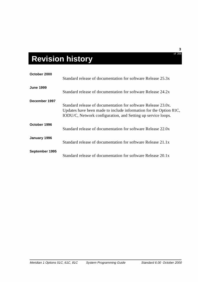
October 2000Standard release of documentation for software Release 25.3x
June 1999Standard release of documentation for software Release 24.2x
December 1997Standard release of documentation for software Release 23.0x. Updates have been made to include information for the Option 81IODU/C, Network configuration, and Setting up service loops.
October 1996Standard release of documentation for software Release 22.0x
January 1996Standard release of documentation for software Release 21.1x
September 1995 Standard release of documentation for software Release 20.1x
Meridian 1 Options 51C, 61C, 81C System Programming Guide Standard 6.00 October 2000

4 of 206
Revision history
4
Meridian 1 Options 51C, 61C, 81C System Programming Guide Standard 6.00 October 2000
5of 206
Table of Contents
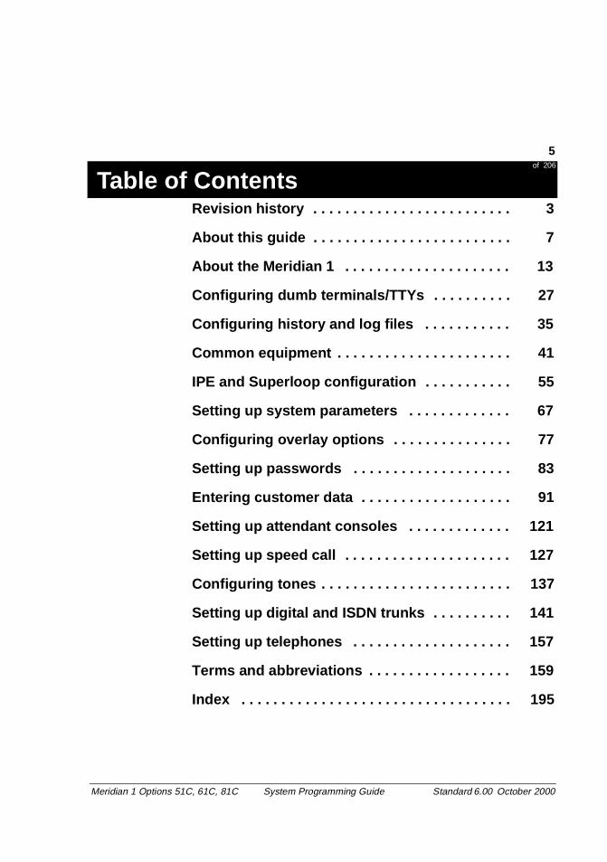
Revision history . . . . . . . . . . . . . . . . . . . . . . . . . 3About this guide . . . . . . . . . . . . . . . . . . . . . . . . . 7
About the Meridian 1 . . . . . . . . . . . . . . . . . . . . . 13
Configuring dumb terminals/TTYs . . . . . . . . . . 27
Configuring history and log files . . . . . . . . . . . 35
Common equipment . . . . . . . . . . . . . . . . . . . . . . 41
IPE and Superloop configuration . . . . . . . . . . . 55
Setting up system parameters . . . . . . . . . . . . . 67
Configuring overlay options . . . . . . . . . . . . . . . 77
Setting up passwords . . . . . . . . . . . . . . . . . . . . 83
Entering customer data . . . . . . . . . . . . . . . . . . . 91
Setting up attendant consoles . . . . . . . . . . . . . 121
Setting up speed call . . . . . . . . . . . . . . . . . . . . . 127
Configuring tones . . . . . . . . . . . . . . . . . . . . . . . . 137
Setting up digital and ISDN trunks . . . . . . . . . . 141
Setting up telephones . . . . . . . . . . . . . . . . . . . . 157
Terms and abbreviations . . . . . . . . . . . . . . . . . . 159
Index . . . . . . . . . . . . . . . . . . . . . . . . . . . . . . . . . . 195
Meridian 1 Options 51C, 61C, 81C System Programming Guide Standard 6.00 October 2000

6
of 206
6
Meridian 1 Options 51C, 61C, 81C System Programming Guide Standard 6.00 October 2000
System Programming Guide 7of 206
About this guide
n) em.
n.
this
About this guide
About this guide About this guide
This guide is intended for the novice Meridian 1 administrator or programmer. Use this guide to perform initial programming on a newly installed Options 51C, 61C, or 81C Meridian 1 system.
This guide provides information, tips, and programming (step-actioexamples to help you program the newly installed Meridian 1 syst
Basic feature programming examplesThe programming examples are of basic features needed to operate a typical Meridian 1 system.
Modify the basic feature examples probably to match the programming required for your system.
The examples are divided into a number of sections, each sectionaddressing one particular aspect of a Meridian 1 system operatioEach section is called a task. A task number appears in the top corner of the page.
Advanced featuresAdvanced features require more explanation and instruction than guide can provide. If your system requires advanced features youare referred to the Nortel Networks Technical Publication (NTP) that covers the advanced feature.
Who should use this guide
How to use this guide
Meridian 1 Options 51C, 61C, 81C System Programming Guide Standard 6.00 October 2000
8 System Programming Guideof 206
About this guide
12
ow
ts.
n
g and
About the Meridian 1About the Meridian 1 introduces the basics of the Meridian 1.
Task sectionsThe main part of this guide is made up of sections which explain hto perform tasks. Each task section has an introduction, and a step-action procedure. Some tasks have diagrams and flow char
Introduction (narrative)The introduction provides you with what you should know about aaspect of Meridian 1 functionality before you program it.
Step-action tablesUse the step-action example part of the task section to guide youthrough programming your Meridian 1 system.
Terms and abbreviations sectionTerms and abbreviations provides a definition or explanation of a number of the terms and abbreviations used in this guide.
Index The index at the back of this guide provides an easy way of findininformation about specific subjects, features, prompts, responses,system messages.
How the sections of this guide work
Meridian 1 Options 51C, 61C, 81C System Programming Guide Standard 6.00 October 2000
System Programming Guide 9of 206
About this guide
hat
s
e
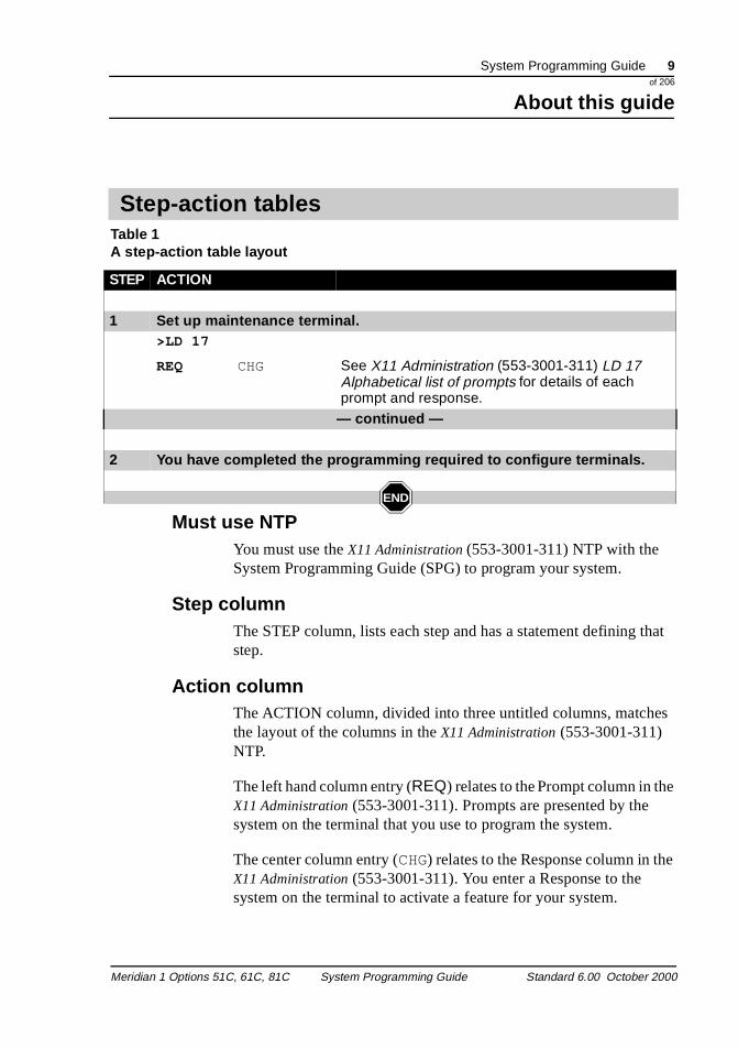
Table 1A step-action table layout
Must use NTPYou must use the X11 Administration (553-3001-311) NTP with the System Programming Guide (SPG) to program your system.
Step columnThe STEP column, lists each step and has a statement defining tstep.
Action columnThe ACTION column, divided into three untitled columns, matchethe layout of the columns in the X11 Administration (553-3001-311) NTP.
The left hand column entry (REQ) relates to the Prompt column in theX11 Administration (553-3001-311). Prompts are presented by the system on the terminal that you use to program the system.
The center column entry (CHG) relates to the Response column in thX11 Administration (553-3001-311). You enter a Response to the system on the terminal to activate a feature for your system.
Step-action tables
STEP ACTION
1 Set up maintenance terminal.>LD 17
REQ CHG See X11 Administration (553-3001-311) LD 17 Alphabetical list of prompts for details of each prompt and response.
— continued —
2 You have completed the programming required to configure terminals.
END
Meridian 1 Options 51C, 61C, 81C System Programming Guide Standard 6.00 October 2000

10 System Programming Guideof 206
About this guide
12
the r
es
am
ow
the
h , or
The right hand column entry (See X11 Administration (553-3001-311) LD 17 Alphabetical list of prompts, for details of each prompt and response.) relates to the Comment column in the X11 Administration (553-3001-311). The Comment column explains theResponse choices, and provides further details, tips, and helpful suggestions about the response choices. For advanced features Comment column refers you to the advanced feature NTP for furthedetails, and instructions.
- continued -The - continued - step indicates that the Step-Action table continuon the next page.
END iconThe END icon indicates the end of the Step-Action table.
Administration tips appear throughout this guide to help you progryour system.
To program your Meridian 1 system, you must understand and follthe information contained in the X11 Administration (553-3001-311) chapters General and Communicating with the Meridian 1.
While you are programming, your system can output messages onterminal. You will need the X11 System Messages Guide (553-3001-411) to understand these messages. You can use the System Look upMessages function as described in X11 Administration (553-3001-311).
Please check with your supplier if you have questions about whicNortel Networks products (such as telephones, software featureshardware) are available in your market area for a given release.
Administration tips
Availability of product
Meridian 1 Options 51C, 61C, 81C System Programming Guide Standard 6.00 October 2000
System Programming Guide 11of 206
About this guide
see
This guide is written to North American English standards. Please the Terms and abbreviations for equivalent terminology. We welcome suggestions for additions to these sections.For versions of this guide in other than North American English, please check with your supplier or with Nortel Networks.
Language standards and translations
Meridian 1 Options 51C, 61C, 81C System Programming Guide Standard 6.00 October 2000

12 System Programming Guideof 206
About this guide
12
Meridian 1 Options 51C, 61C, 81C System Programming Guide Standard 6.00 October 2000
System Programming Guide 13of 206
About the Meridian 1
he ty, , nts
About the Meridian 1
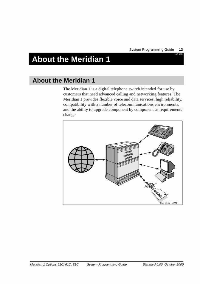
The Meridian 1 is a digital telephone switch intended for use by customers that need advanced calling and networking features. TMeridian 1 provides flexible voice and data services, high reliabilicompatibility with a number of telecommunications environmentsand the ability to upgrade component by component as requiremechange.
About the Meridian 1
553-0117T AM1
Meridian 1 Options 51C, 61C, 81C System Programming Guide Standard 6.00 October 2000
14 System Programming Guideof 206
About the Meridian 1
26
ws:
mn can
hed
,
Meridian 1 descriptionThe Meridian 1 product line consists of three system types as follo
� Meridian 1 Option 51C
� Meridian 1 Option 61C
� Meridian 1 Option 81C
A system Option is made up of Universal Equipment Modules (UEMs) stacked one on top of another to form a column. Each colucontains a pedestal, a top cap, and up to four modules. A systemhave one column or multiple columns.
Each UEM is a self-contained unit with the following elements:
� a cardcage and backplane
� power and ground cabling
� power units
� I/O panels
� circuit cards
When the cardcage is installed, the function of the UEM is establisand the module is no longer “universal.” Meridian 1 modules are as follows:
� NT4N41 Core/Network Module for Meridian 1 Options 51C, 61Cand 81C
� NT8D35 Network Modulerequired for Meridian 1 Options 51C, 61C, and 81C
� NT8D37 Intelligent Peripheral Equipment (IPE) Modulerequired for Meridian 1 Options 51C, 61C, and 81C.
Note: In addition, modules that house equipment for specific applications, such as Meridian Mail and Meridian Link, can beincluded in a column.
Meridian 1 Options 51C, 61C, 81C System Programming Guide Standard 6.00 October 2000
System Programming Guide 15of 206
About the Meridian 1
nd lies hest
al
rk
rk
The pedestal generally houses a blower unit, air filter, Power Distribution Unit (PDU), and System Monitor.
The top cap provides airflow exits, input/output (I/O) cable entry aexit, and overhead cable-rack mounting. Thermal sensor assembfor the column are attached to a perforated panel on top of the higmodule in the column, under the top cap.
To comply with FCC and CSA standards for containing electromagnetic interference and radio frequency interference (EMI/RFI), spacer kits connect the columns in a multiple-column system
System typesMeridian 1 Option 51CMeridian 1 Option 51C is a single-CPU system with one Core/Network Module, containing a half-network group. One Core/Network Module and one IPE Module are required. AdditionIPE Modules and application modules can be used.
Meridian 1 Option 61CMeridian 1 Option 61C is a dual-CPU system with two Core/NetwoModules, fully redundant memory, and a full-network group. Two Core/Network Modules and one IPE Module are required.
Meridian 1 Option 81CMeridian 1 Option 81C is a dual-CPU system with two Core/NetwoModules, fully redundant memory, and up to eight full-network groups. Meridian 1 Option 81C is equipped with two redundant input/output processors and disk drive unit combination packs.
The following modules are required:
� two Core/Network Modules (provide one network group)
� a minimum of two Network Modules (provides one network group)
� a minimum of one IPE Module
Meridian 1 Options 51C, 61C, 81C System Programming Guide Standard 6.00 October 2000
16 System Programming Guideof 206
About the Meridian 1
26
at
f nd
e read
ns um
m,
of
are
tion
Additional Network and IPE Modules are required for additional network groups, and application modules can also be used.
Software Meridian 1 software programs consist of instruction sequences thcontrol call processing, peripheral equipment, administration, andmaintenance functions. Several generic software programs with optional feature packages are available.
Office dataOffice data describes the characteristics of the system in terms oconfiguration and call-dependent information, such as features aservices. Office data is arranged in blocks defining peripheral equipment, system configuration, and transient data.
Resident programs Resident programs stay in memory during system operation. Somresident programs are permanently programmed into the system only memory (ROM). Other resident programs are automatically loaded into the system memory when the system is turned on.
Note 1: The Meridian 1 Option 51C runs on one CP PII: Call Processor Pentium II (A0810496) card. The Meridian 1 Optio61C, and 81C run on either of two CP PII: Call Processor PentiII cards.
All software programs, including the non-resident programs listed in the following section are resident in, and accessible frothe memory on the cards listed above.
Non-resident programs Non-resident programs (overlays) are loaded into an overlay areathe system memory to perform specific tasks. Overlays refer to non-resident administration and maintenance programs. Overlaysidentified by the letters LD and numbers, for example LD 17. Administration overlays allow data entry to customize Meridian 1 system features, telephones, trunk groups, hardware, and data devices. Maintenance overlays diagnose Meridian 1 system operaand faults.
Meridian 1 Options 51C, 61C, 81C System Programming Guide Standard 6.00 October 2000
System Programming Guide 17of 206
About the Meridian 1
can
ram ats.
l
s of
the
lts.
be nel,
the
Only one program can be loaded at a time. Non-resident programsload automatically, under program control, or manually through software commands.
You can manually load non-resident programs into the system memory using the system terminal or maintenance telephone.
The non-resident programs provide the system interface for maintenance, service change, and traffic measurement. Each progis independent and has its own specific set of commands and formThese programs do not interfere with system traffic or normal calprocessing.
There are five types of non-resident program:
� service change and print routines
� maintenance diagnostics
� traffic
� equipment data dump
� software audit
Service change and print routinesUse service administration programs to create or modify all aspectthe system, from individual feature key assignments to complete system configurations.
There are also programs and print routines for retrieving data fromsystem to check the status of office data assignments.
Maintenance diagnosticsDiagnostic programs are the primary tools for clearing system fauUse diagnostic programs to automatically or manually test both common equipment and peripheral equipment. The programs canloaded into the overlay area at the request of maintenance personor as part of a daily maintenance routine automatically initiated by system at a specified time.
Meridian 1 Options 51C, 61C, 81C System Programming Guide Standard 6.00 October 2000
18 System Programming Guideof 206
About the Meridian 1
26
. fers
olds.
ram,
ice
tion
with
d
sor ry
port
TrafficAll systems are equipped with traffic data accumulation programsThere is a traffic print program that examines the schedules, transdata from accumulating to holding registers in accordance with schedules, and prints the traffic data. In addition, there is a traffic program used to query and modify schedules, options, and thresh
Equipment data dumpAfter making service changes, you transfer the changes to disk inorder to save them. When you run the equipment data dump progall the office data in the read/write memory is written to the systemdisk. You can run the program automatically during the midnight routine or on a conditional basis (for example, after making a servchange). You can run the program manually through the system terminal.
You can also use the data dump program to install a new genericsoftware version or issue and capture protected data store informa(such as speed call lists) that a user might change.
Software auditThis program monitors system operation and gives an indication of the general state of the system. The program is concerned mainly the system software. When a software problem is encountered, the program attempts to clear the problem automatically.
FirmwareFirmware provides fundamental programs consisting of hard-wirelogic instructions stored in programmable read-only memory (PROM). Firmware programs manipulate data in the central procesand control input/output operations, error diagnostics, and recoveroutines.
Meridian 1 Options 51C, 61C, and 81C Core processor cards supextensive networking, and provide intensive use of software features and applications, including call centers of up to 1000 agents.
Advanced Meridian 1 system architecture
Meridian 1 Options 51C, 61C, 81C System Programming Guide Standard 6.00 October 2000
System Programming Guide 19of 206
About the Meridian 1
ad lays essing
1 rk
g
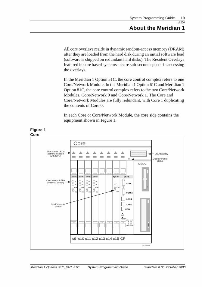
All core overlays reside in dynamic random-access memory (DRAM) after they are loaded from the hard disk during an initial software lo(software is shipped on redundant hard disks). The Resident Overfeatured in core based systems ensure sub-second speeds in accthe overlays.
In the Meridian 1 Option 51C, the core control complex refers to one Core/Network Module. In the Meridian 1 Option 61C and MeridianOption 81C, the core control complex refers to the two Core/NetwoModules, Core/Network 0 and Core/Network 1. The Core and Core/Network Modules are fully redundant, with Core 1 duplicatinthe contents of Core 0.
In each Core or Core/Network Module, the core side contains theequipment shown in Figure 1.
Figure 1Core
Enb
Dis
Sys Util
LAN 1
USB
INIT
RESETALRM SPKR
HDD PWR
COM 2
cCNI
A
B
Enb
Dis
cCNI
A
B
Enb
Dis
cCNI
A
B
Enb
Dis
cCNI
A
B
Enb
Dis
LAN 2
COM 1
CP PII
MMDU
Core
c9 c10 c11 c12 c13 c14 c15 CP
553-9124
Display Panelstatus
LCD DisplaySlot status LEDs(communication
with CPU)
Card status LEDs(internal check)
Shelf disable switch
Meridian 1 Options 51C, 61C, 81C System Programming Guide Standard 6.00 October 2000
20 System Programming Guideof 206
About the Meridian 1
26
each to a f at
his re
s tility
ge rnet
d
Core circuit cardscCNI: cPCI Core to Network Interface (NT4N65AA)The cCNI cards connect the Core module cards to the 3PE cards in theNetwork modules.
Each Core module contains between one and four cCNI cards. BecausecCNI card can connect to two Network groups, each Core is connectedminimum of two groups and a maximum of eight groups. The number ocCNI cards in a system depends on the number of Network groups in thsystem.
cCNI Transition card: cPCI Core to Network Interface Transition (NT4N66AA)The cCNI Transition cards provide the cable connections to the 3PE Termination Panel in the back of the module.
Sys Util: System Utility (NT4N67AA)The System Utility card provides additional functions for the CP II card. Tcard also includes a switch on the faceplate to enable or disable the Cocards.
System Utility Transition card (NT4N68AA)The System Utility Transition card provides connections for the securitydevice, the system monitor, and the status panel. This Transition card imounted on the back of the backplane (back side) behind the System Ucard.
CP PII: Call Processor Pentium II (A0810496)The CP PII card contains a Pentium II processor to process calls, manamemory, and monitor the system. This card also provides serial and Etheinterfaces used to manage the system.
MMDU: Multi-Media Disk Unit (NT4N43AA)This MMDU card contains the drives to store system software andatabases. This card includes:
� a hard disk to store the system database and software
� a floppy disk to install software or back up databases
� a CD-ROM to install system software
Meridian 1 Options 51C, 61C, 81C System Programming Guide Standard 6.00 October 2000
System Programming Guide 21of 206
About the Meridian 1
ides
f d
y e
ne
e to to
Customization The information that describes specific system configuration and associated peripheral equipment is called office data. This data resin the system memory and on disk.
Office data describes the characteristics of the system in terms oconfiguration and call-dependent information, such as features anservices. Office data is arranged in blocks defining peripheral equipment, system configuration, and transient data.
Prepare for the configuration of your Meridian 1 before it arrives bplanning the new telephone system. Your company needs to makdecisions about:
� telephone extensions, including telephone numbers, types of telephones, and telephone options
� attendant consoles
� features
� value-added servers for applications such as Meridian Mail, Interactive Voice Response, or Automatic Call Distribution
� trunks linking the Meridian 1 to other telephone systems, including the public telephone network
Documents are available to help your company plan their telephosystem. For information about hardware planning, refer to Installation Planning (553-3001-120). For more information about feature planning and provisioning, refer to System Engineering (553-3001-151).
When your company plans a new telephone system, use this guidcreate implementation sheets or worksheets listing the responsesspecific prompts in various Meridian 1 overlay programs.
Planning for your Meridian 1
Meridian 1 Options 51C, 61C, 81C System Programming Guide Standard 6.00 October 2000
22 System Programming Guideof 206
About the Meridian 1
26
To n 1
der
ion.
24 s not o
s to
that
eed to a
itles er to
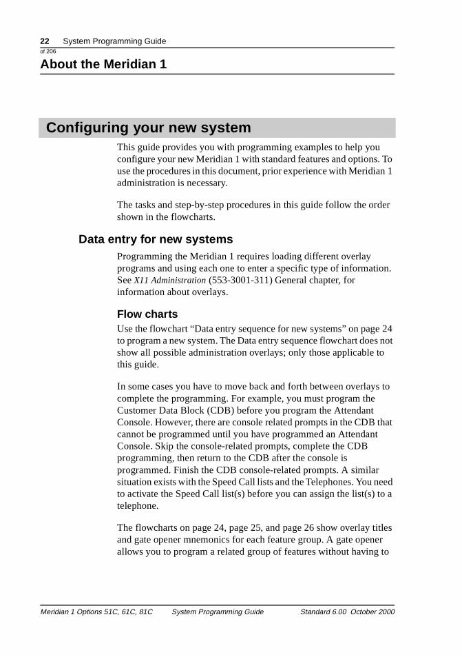
This guide provides you with programming examples to help youconfigure your new Meridian 1 with standard features and options.use the procedures in this document, prior experience with Meridiaadministration is necessary.
The tasks and step-by-step procedures in this guide follow the orshown in the flowcharts.
Data entry for new systemsProgramming the Meridian 1 requires loading different overlay programs and using each one to enter a specific type of informatSee X11 Administration (553-3001-311) General chapter, for information about overlays.
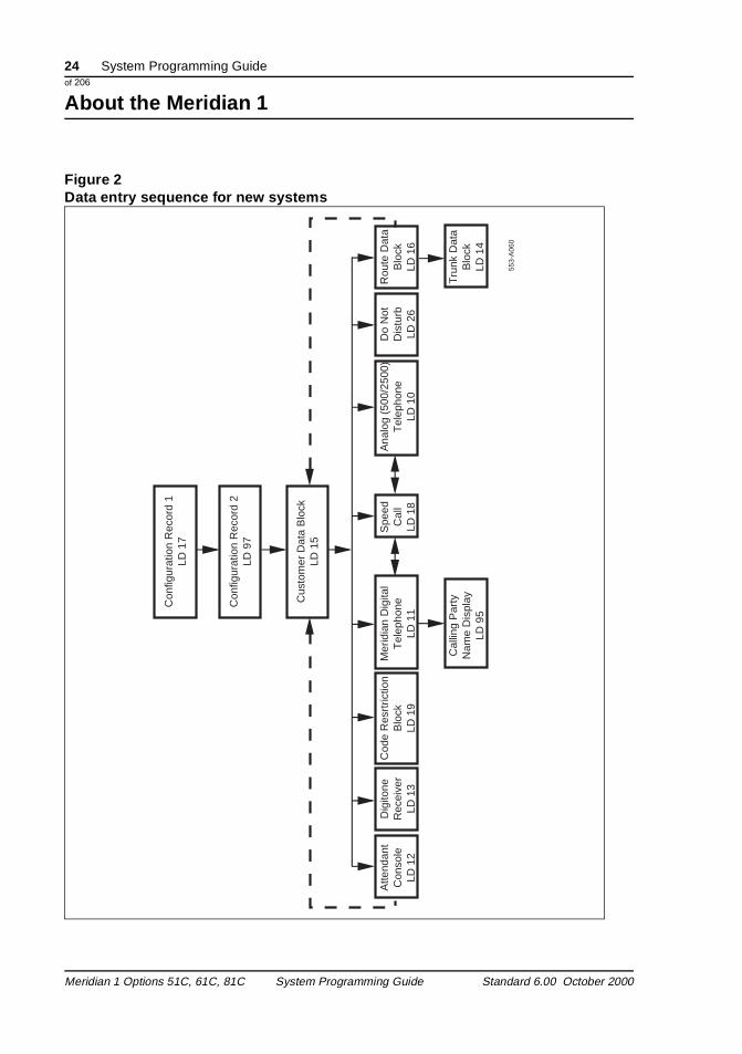
Flow chartsUse the flowchart “Data entry sequence for new systems” on pageto program a new system. The Data entry sequence flowchart doeshow all possible administration overlays; only those applicable tthis guide.
In some cases you have to move back and forth between overlaycomplete the programming. For example, you must program the Customer Data Block (CDB) before you program the Attendant Console. However, there are console related prompts in the CDB cannot be programmed until you have programmed an AttendantConsole. Skip the console-related prompts, complete the CDB programming, then return to the CDB after the console is programmed. Finish the CDB console-related prompts. A similar situation exists with the Speed Call lists and the Telephones. You nto activate the Speed Call list(s) before you can assign the list(s) telephone.
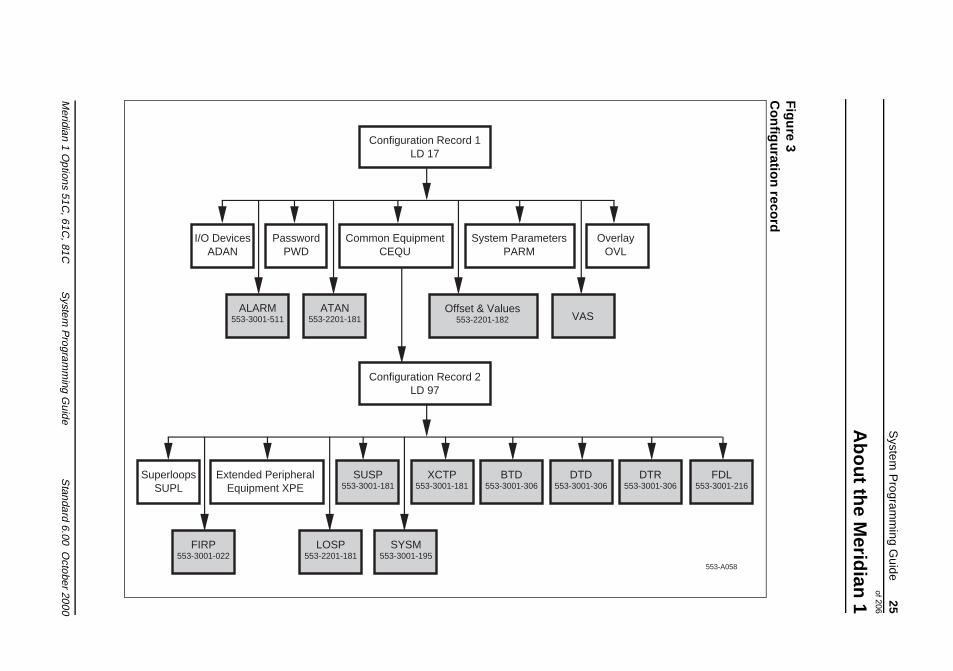
The flowcharts on page 24, page 25, and page 26 show overlay tand gate opener mnemonics for each feature group. A gate openallows you to program a related group of features without having
Configuring your new system
Meridian 1 Options 51C, 61C, 81C System Programming Guide Standard 6.00 October 2000
System Programming Guide 23of 206
About the Meridian 1
n in the
step through all prompts of an overlay. NTP references are showthe flowchart shaded boxes for those features and options beyondscope of this guide.
WorksheetsSeveral worksheets are available to help you plan for and perform configuration and feature implementation on the Meridian 1. Worksheets are forms that serve as templates for your installationplanning. Worksheets are avai30lable in System Engineering (553-3001-151).
Meridian 1 Options 51C, 61C, 81C System Programming Guide Standard 6.00 October 2000
24 System Programming Guideof 206
About the Meridian 1
26
Figure 2Data entry sequence for new systems
Cus
tom
er D
ata
Blo
ckLD
15
Atte
ndan
tC
onso
leLD
12
Dig
itone
Rec
eive
rLD
13
Spe
edC
all
LD 1
8
Cod
e R
esrt
rictio
nB
lock
LD 1
9
Mer
idia
n D
igita
lT
elep
hone
LD 1
1
Cal
ling
Par
tyN
ame
Dis
play
LD 9
5
553-
A06
0
Do
Not
Dis
turb
LD 2
6
Ana
log
(500
/250
0)T
elep
hone
LD 1
0
Tru
nk D
ata
Blo
ckLD
14
Rou
te D
ata
Blo
ckLD
16
Con
figur
atio
n R
ecor
d 2
LD 9
7
Con
figur
atio
n R
ecor
d 1
LD 1
7
Meridian 1 Options 51C, 61C, 81C System Programming Guide Standard 6.00 October 2000
System
Program
ming G
uide 25
of 206
About the M
eridian 1
Meridian 1 O
ptions 51C, 61C
, 81CS
ystem P
rogramm
ing Guide
Standard 6.00 O
ctober2000
Figure 3
Configuration record
Configuration Record 1
y
553-A058
DTR53-3001-306
FDL553-3001-216
LD 17
Common EquipmentCEQU
System ParametersPARM
OverlaOVL
I/O DevicesADAN
PasswordPWD
Offset & Values553-2201-182 VAS
ATAN553-2201-181
ALARM553-3001-511
Configuration Record 2LD 97
SUSP553-3001-181
XCTP553-3001-181
DTD553-3001-306
SuperloopsSUPL
Extended PeripheralEquipment XPE
FIRP553-3001-022
LOSP553-2201-181
SYSM553-3001-195
5BTD
553-3001-306
26 S
ystem P
rogramm
ing Guide
of 206
About the M
eridian 1
Meridian 1 O
ptions
26
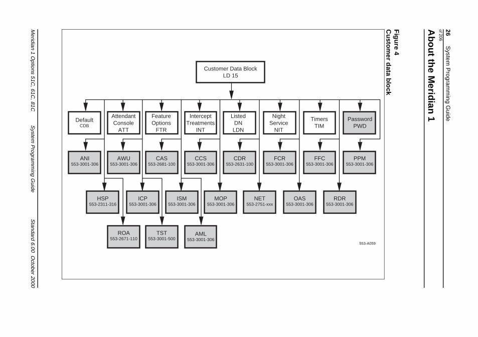
Figure 4
Custom
er data block
553-A059
Customer Data Block
PasswordPWD
TimersTIM
OAS3001-306
RDR553-3001-306
PPM553-3001-306
FFC553-3001-306
51C, 61C
, 81CS
ystem P
rogramm
ing Guide
Standard 6.00 O
ctober2000
LD 15
AttendantConsole
ATT
InterceptTreatments
INT
FeatureOptions
FTR
ListedDN
LDN
NightService
NIT
HSP553-2311-316
ISM553-3001-306
ICP553-3001-306
MOP553-3001-306 553-
NET553-2751-xxx
FCR553-3001-306
CDR553-2631-100
CCS553-3001-306
CAS553-2681-100
AWU553-3001-306
ANI553-3001-306
DefaultCDB
TST553-3001-500
ROA553-2671-110
AML553-3001-306
System Programming Guide 27of 206
Configuring dumb terminals/TTYs
1T A S K
a r
sed ls, re.
Configuring dumb terminals/TTYsTerminals
Task 1Basic configur tion
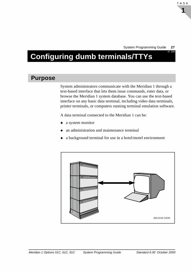
System administrators communicate with the Meridian 1 through text-based interface that lets them issue commands, enter data, obrowse the Meridian 1 system database. You can use the text-bainterface on any basic data terminal, including video data terminaprinter terminals, or computers running terminal emulation softwa
A data terminal connected to the Meridian 1 can be:
� a system monitor
� an administration and maintenance terminal
� a background terminal for use in a hotel/motel environment
Purpose
553-0120 CI/OD
Meridian 1 Options 51C, 61C, 81C System Programming Guide Standard 6.00 October 2000
28 System Programming Guideof 206
Configuring dumb terminals/TTYs
1T A S K 34
by
th to
:
e, d
e to
1.
A terminal is either connected directly to the Meridian 1, allowingprogrammers and administrators to work onsite, or it is connectedway of modems, allowing remote access.
The Meridian 1 has one pre-configured terminal, called a Single Terminal Access (STA). Use the STA terminal to communicate withe Meridian 1. Use the procedures and information provided hereconfigure any additional terminals.
The Meridian 1 uses data terminals in a number of ways, such as
� a system monitor
� a background terminal
� a maintenance terminal
� a service change terminal
� a traffic terminal
If you do not know the functions each terminal you configure servrefer to your installation workorder. Brief descriptions are providebelow.
System monitor A system monitor operates as an output device only, displaying power, cooling, and general system error and status reporting.
To configure a terminal as a system monitor, enter YES in responsthe XMS prompt in LD 17.
Background terminal A background terminal provides access to users in Hospitality environments, that allows them to monitor and control the Meridian
To configure a terminal as a background terminal, enter BGD in response to the USER prompt in LD 17.
Terminal types
Meridian 1 Options 51C, 61C, 81C System Programming Guide Standard 6.00 October 2000
System Programming Guide 29of 206
Configuring dumb terminals/TTYs
1T A S K
ges,
m,
nds.
in
Maintenance terminal A maintenance terminal outputs system and maintenance messaincluding AUD, BUG and ERR messages.
To configure a terminal as a maintenance terminal, enter MTC in response to the USER prompt in LD 17.
Service change terminal A service change terminal provids access to the Meridian 1 systecustomer and set database, and allows programmers and administrators to review or change the database or issue comma
To configure a terminal as a service change terminal, enter SCH response to the USER prompt in LD 17.
Traffic terminal A service traffic terminal reports on traffic levels and events to programmers and administrators.
To configure a terminal as a traffic terminal, enter TRF in response to the USER prompt in LD 17.
The Meridian 1 communicates with terminals through Serial DataInterface (SDI) ports. These SDI ports exist on several of the Meridian 1 circuit cards. These circuit cards include:
� NT8D41 Dual Port Serial Data Interface Paddle Board
� QPC139 Serial Data Interface
� QPC841 4-Port Serial Data Interface Card
� NT6D80 Multi-Purpose Serial Data Link Card
� QPC513 Enhanced Serial Data Interface Pack
� NT5K35 D-channel Interface Card
� NT6D11 D-channel Interface Card
Serial data interface ports
Meridian 1 Options 51C, 61C, 81C System Programming Guide Standard 6.00 October 2000
30 System Programming Guideof 206
Configuring dumb terminals/TTYs
1T A S K 34
ey rial . and
gs. and
g
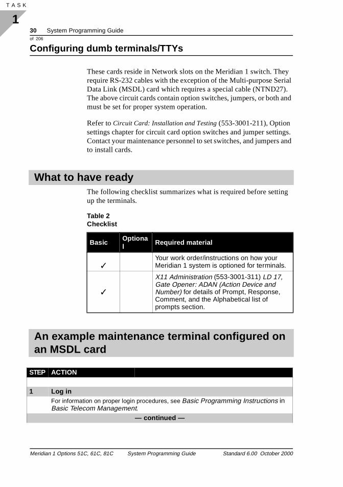
These cards reside in Network slots on the Meridian 1 switch. Threquire RS-232 cables with the exception of the Multi-purpose SeData Link (MSDL) card which requires a special cable (NTND27)The above circuit cards contain option switches, jumpers, or both must be set for proper system operation.
Refer to Circuit Card: Installation and Testing (553-3001-211), Option settings chapter for circuit card option switches and jumper settinContact your maintenance personnel to set switches, and jumpersto install cards.
The following checklist summarizes what is required before settinup the terminals.
What to have ready
Table 2 Checklist
BasicOptional
Required material
✓Your work order/instructions on how your Meridian 1 system is optioned for terminals.
✓
X11 Administration (553-3001-311) LD 17, Gate Opener: ADAN (Action Device and Number) for details of Prompt, Response, Comment, and the Alphabetical list of prompts section.
An example maintenance terminal configured on an MSDL card
STEP ACTION
1 Log inFor information on proper login procedures, see Basic Programming Instructions in Basic Telecom Management.
— continued —
Meridian 1 Options 51C, 61C, 81C System Programming Guide Standard 6.00 October 2000
System Programming Guide 31of 206
Configuring dumb terminals/TTYs
1T A S K
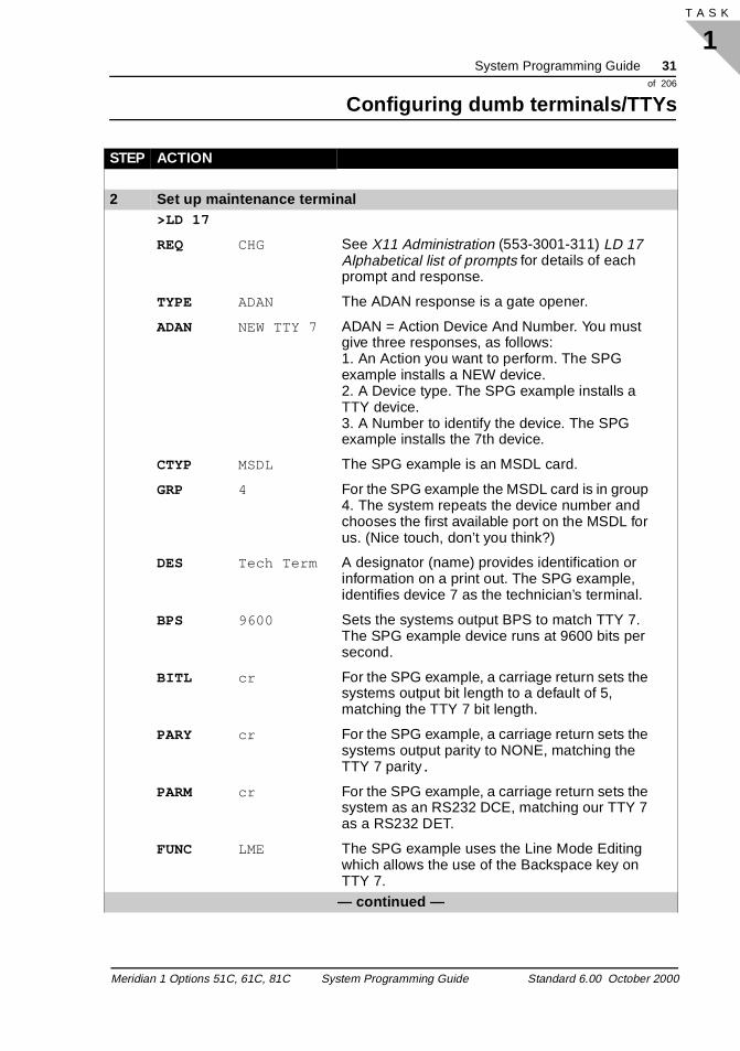
2 Set up maintenance terminal>LD 17
REQ CHG See X11 Administration (553-3001-311) LD 17 Alphabetical list of prompts for details of each prompt and response.
TYPE ADAN The ADAN response is a gate opener.
ADAN NEW TTY 7 ADAN = Action Device And Number. You must give three responses, as follows: 1. An Action you want to perform. The SPG example installs a NEW device.2. A Device type. The SPG example installs a TTY device.3. A Number to identify the device. The SPG example installs the 7th device.
CTYP MSDL The SPG example is an MSDL card.
GRP 4 For the SPG example the MSDL card is in group 4. The system repeats the device number and chooses the first available port on the MSDL for us. (Nice touch, don’t you think?)
DES Tech Term A designator (name) provides identification or information on a print out. The SPG example, identifies device 7 as the technician’s terminal.
BPS 9600 Sets the systems output BPS to match TTY 7. The SPG example device runs at 9600 bits per second.
BITL cr For the SPG example, a carriage return sets the systems output bit length to a default of 5, matching the TTY 7 bit length.
PARY cr For the SPG example, a carriage return sets the systems output parity to NONE, matching the TTY 7 parity.
PARM cr For the SPG example, a carriage return sets the system as an RS232 DCE, matching our TTY 7 as a RS232 DET.
FUNC LME The SPG example uses the Line Mode Editing which allows the use of the Backspace key on TTY 7.
— continued —
STEP ACTION
Meridian 1 Options 51C, 61C, 81C System Programming Guide Standard 6.00 October 2000
32 System Programming Guideof 206
Configuring dumb terminals/TTYs
1T A S K 34
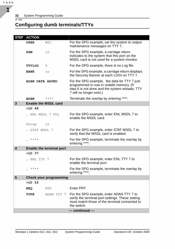
USER MTC For the SPG example, set the system to output maintenance messages on TTY 7.
XSM cr For the SPG example, a carriage return indicates to the system that this port on the MSDL card is not used for a system monitor.
TTYLOG 0 For the SPG example, there is no Log file.
BANR cr For the SPG example, a carriage return displays the Security Banner at each LOGI on TTY 7.
ADAN DATA SAVED For the SPG example, the data for TTY 7 just programmed is now in volatile memory. (If step 6 is not done and the system reloads, TTY 7 will no longer exist.)
ADAN **** Terminate the overlay by entering ****.3 Enable the MSDL card
>LD 48
. ENL MSDL 7 FDL For the SPG example, enter ENL MSDL 7 to enable the MSDL card.
Group cr
. STAT MSDL 7 For the SPG example, enter STAT MSDL 7 to verify that the MSDL card is enabled.
. **** For the SPG example, terminate the overlay by entering ****.
4 Enable the terminal port>LD 37
. ENL TTY 7 For the SPG example, enter ENL TTY 7 to enable the terminal port.
. **** For the SPG example, terminate the overlay by entering ****.
5 Check your programming>LD 22
REQ PRT Enter PRT.
TYPE ADAN TTY 7 For the SPG example, enter ADAN TTY 7 to verify the terminal port settings. These setting must match those of the terminal connected to the switch.
— continued —
STEP ACTION
Meridian 1 Options 51C, 61C, 81C System Programming Guide Standard 6.00 October 2000
System Programming Guide 33of 206
Configuring dumb terminals/TTYs
1T A S K
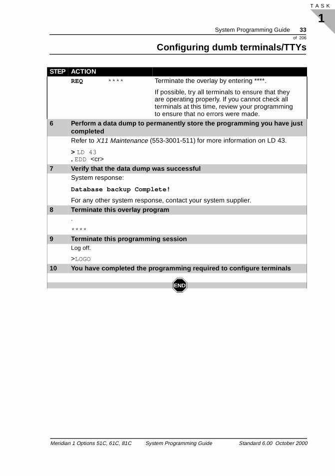
REQ **** Terminate the overlay by entering ****.
If possible, try all terminals to ensure that they are operating properly. If you cannot check all terminals at this time, review your programming to ensure that no errors were made.
6 Perform a data dump to permanently store the programming you have just completedRefer to X11 Maintenance (553-3001-511) for more information on LD 43.
> LD 43. EDD <cr>
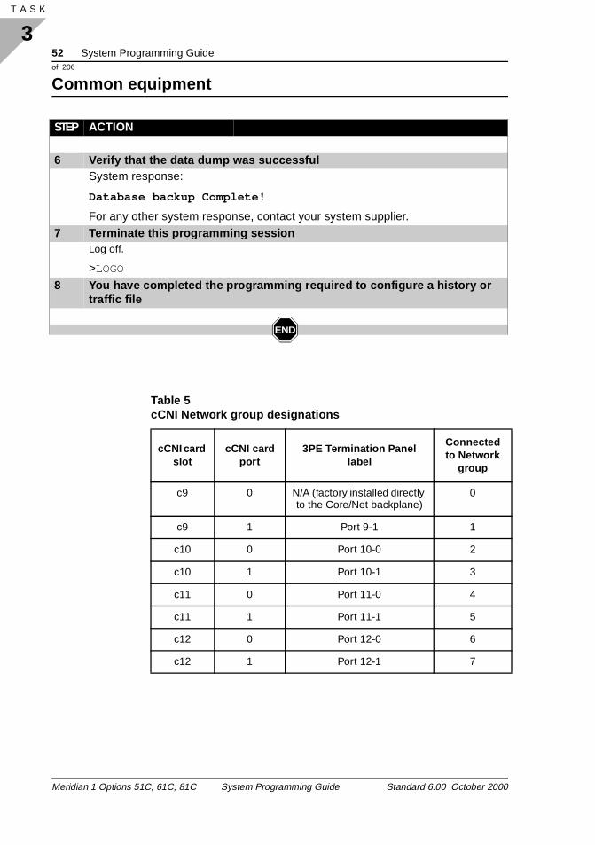
7 Verify that the data dump was successfulSystem response:
Database backup Complete!
For any other system response, contact your system supplier.8 Terminate this overlay program
.
****
9 Terminate this programming sessionLog off.
>LOGO
10 You have completed the programming required to configure terminals
END
STEP ACTION
Meridian 1 Options 51C, 61C, 81C System Programming Guide Standard 6.00 October 2000

34 System Programming Guideof 206
Configuring dumb terminals/TTYs
1T A S K 34
Meridian 1 Options 51C, 61C, 81C System Programming Guide Standard 6.00 October 2000
System Programming Guide 35of 206
Configuring history and log files
2T A S K
fic. rs.
ge is ou ges
on
you ile tion.
T le turn data
Configuring history and log filesHistory and log files
Task 2Basic configuration
The Meridian 1 maintains a running log of system events and trafThis information is stored in log and history files, or output to printe
If you have a printer connected to the system, each system messaprinted as it is received. If you do not have a printer connected, ycan use the History File to store a limited number of system messain protected memory. The contents of the file can then be printeddemand. The messages stored are specified on a system basis and canbe one or more of the following types:
� customer service changes (CSC)
� maintenance messages (MTC)
� service changes (SCH)
� software errors (BUG)
� initialization and sysload messages (INI and SYS)
� traffic messages (TRF)
The contents of the History File are erased during a sysload or if change the History File’s length. However, because the History Fis located in protected data store, the contents survive an initializa
You can change the length of the History File with the prompt HISin the Configuration Record (LD 17). The maximum length of the fidepends on the amount of protected data store available, which independs on the number of system features that require protectedstore.
Purpose
History file feature
Meridian 1 Options 51C, 61C, 81C System Programming Guide Standard 6.00 October 2000
36 System Programming Guideof 206
Configuring history and log files
2T A S K 40
y
d ties
le
n
can
If the History File is full, the first messages stored are replaced bincoming messages. If this happens, the system gives a “file overflow” message at the start of a printout so you know some information has been replaced by newer messages.
With the Multi-User Login feature enabled, the log files associatewith system TTY terminals record messages relating to such activias service changes, traffic (if not redirected to a Traffic Log File), CDR activity, software bugs. Messages recorded in a TTY Log Fiare not written to the History File.
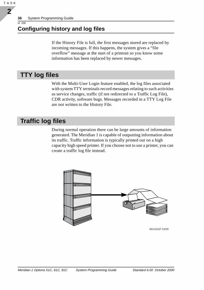
During normal operation there can be large amounts of informatiogenerated. The Meridian 1 is capable of outputting information about its traffic. Traffic information is typically printed out on a high capacity high speed printer. If you choose not to use a printer, youcreate a traffic log file instead.
TTY log files
Traffic log files
553-0123T CI/OD
Meridian 1 Options 51C, 61C, 81C System Programming Guide Standard 6.00 October 2000
System Programming Guide 37of 206
Configuring history and log files
2T A S K
se
re
fic
t ows
g
You can create one traffic log file. All system-generated traffic reportsare recorded in that file rather than in the History File, making thereports more accessible.
Log size You can specify a size for the traffic log. The larger the log, the momemory it uses up and the greater its ability to buffer during overflow conditions.
Traffic parametersWhen you have created the traffic log file, set traffic monitoring parameters in LD 2. For more information about LD 2 and the trafparameters, refer to X11 Administration (553-3001-311).
After adding or changing an I/O device through the ADAN prompsequence, the data is saved before ADAN is reprompted. This allyou to exit LD 17 with **** after I/O changes without having to carriage return through the remaining prompts.
The following checklist summarizes what is required before settinup your history and traffic log files.
Administration tips
What to have ready
Table 3 Checklist
Basic Optional Preparation
✓Your work order/instructions on how your Meridian 1 system is optioned for history files.
✓
X11 Administration (553-3001-311) LD 17, Gate Opener: ADAN (Action Device and Number) for details of Prompt, Response, Comment, and the Alphabetical list of prompts section.
Meridian 1 Options 51C, 61C, 81C System Programming Guide Standard 6.00 October 2000
38 System Programming Guideof 206
Configuring history and log files
2T A S K 40
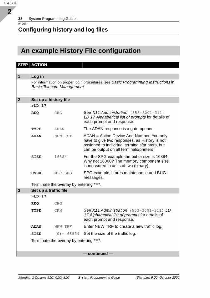
An example History File configuration
STEP ACTION
1 Log inFor information on proper login procedures, see Basic Programming Instructions in Basic Telecom Management.
2 Set up a history file>LD 17
REQ CHG See X11 Administration (553-3001-311) LD 17 Alphabetical list of prompts for details of each prompt and response.
TYPE ADAN The ADAN response is a gate opener.
ADAN NEW HST ADAN = Action Device And Number. You only have to give two responses, as History is not assigned to individual terminals/printers, but can be output on all terminals/printers
SIZE 16384 For the SPG example the buffer size is 16384. Why not 16000? The memory component size is measured in units of two (binary).
USER MTC BUG SPG example, stores maintenance and BUG messages.
Terminate the overlay by entering ****.3 Set up a traffic file
>LD 17
REQ CHG
TYPE CFN See X11 Administration (553-3001-311) LD 17 Alphabetical list of prompts for details of each prompt and response.
ADAN NEW TRF Enter NEW TRF to create a new traffic log.
SIZE (0)- 65534 Set the size of the traffic log.
Terminate the overlay by entering ****.
— continued —
Meridian 1 Options 51C, 61C, 81C System Programming Guide Standard 6.00 October 2000
System Programming Guide 39of 206
Configuring history and log files
2T A S K
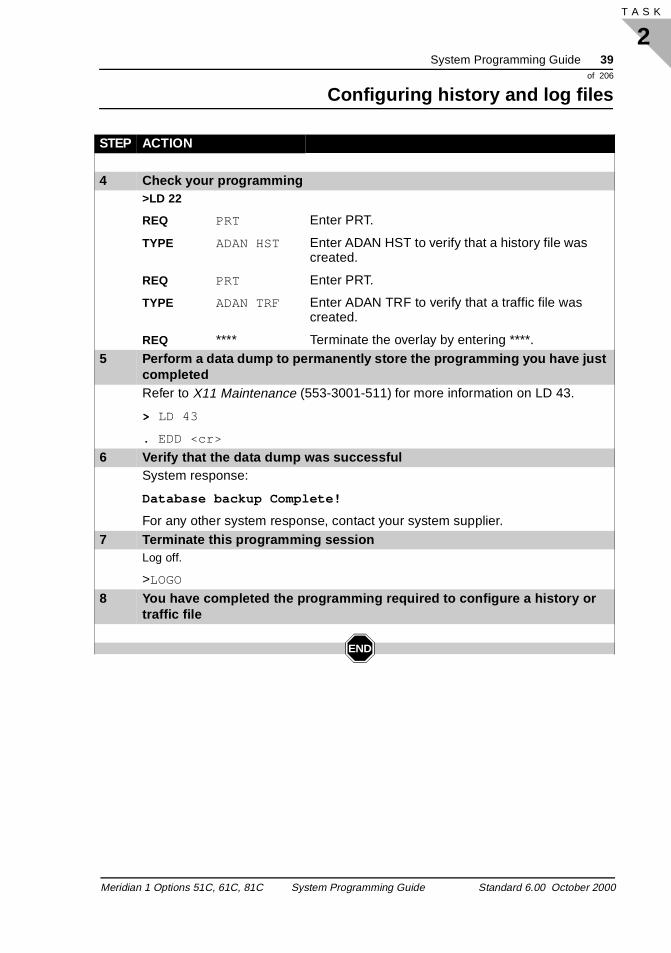
4 Check your programming>LD 22
REQ PRT Enter PRT.
TYPE ADAN HST Enter ADAN HST to verify that a history file was created.
REQ PRT Enter PRT.
TYPE ADAN TRF Enter ADAN TRF to verify that a traffic file was created.
REQ **** Terminate the overlay by entering ****.5 Perform a data dump to permanently store the programming you have just
completedRefer to X11 Maintenance (553-3001-511) for more information on LD 43.
> LD 43
. EDD <cr>
6 Verify that the data dump was successfulSystem response:
Database backup Complete!
For any other system response, contact your system supplier.7 Terminate this programming session
Log off.
>LOGO
8 You have completed the programming required to configure a history or traffic file
END
STEP ACTION
Meridian 1 Options 51C, 61C, 81C System Programming Guide Standard 6.00 October 2000

40 System Programming Guideof 206
Configuring history and log files
2T A S K 40
Meridian 1 Options 51C, 61C, 81C System Programming Guide Standard 6.00 October 2000
System Programming Guide 41of 206
Common equipment
3T A S K
of lso mory
ce
l e,
ny or
Common equipmentLoops
Task 3Task numberBasic configuration
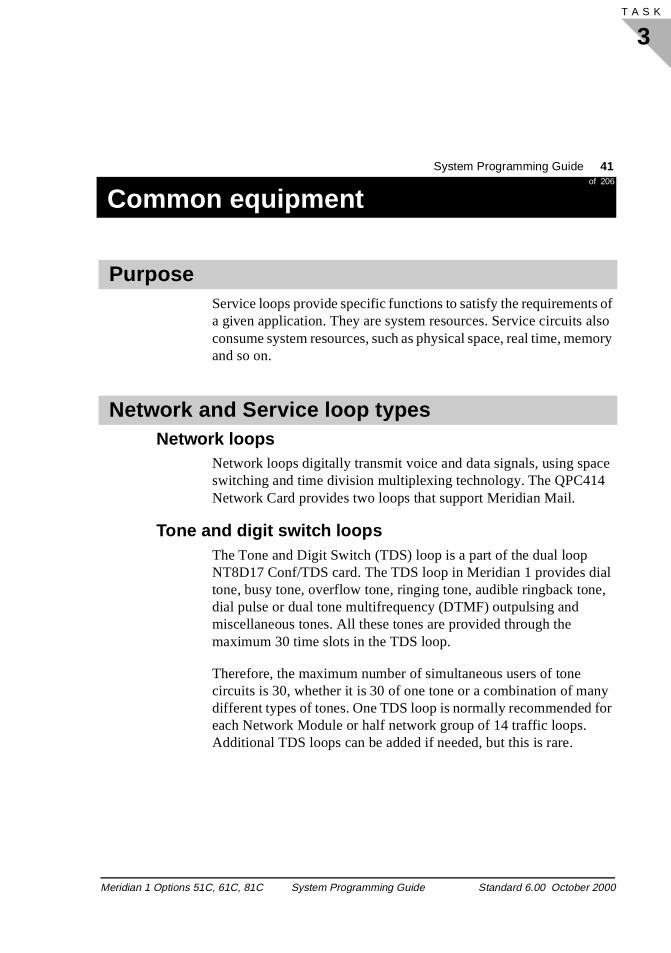
Service loops provide specific functions to satisfy the requirementsa given application. They are system resources. Service circuits aconsume system resources, such as physical space, real time, meand so on.
Network loops Network loops digitally transmit voice and data signals, using spaswitching and time division multiplexing technology. The QPC414Network Card provides two loops that support Meridian Mail.
Tone and digit switch loops The Tone and Digit Switch (TDS) loop is a part of the dual loop NT8D17 Conf/TDS card. The TDS loop in Meridian 1 provides diatone, busy tone, overflow tone, ringing tone, audible ringback tondial pulse or dual tone multifrequency (DTMF) outpulsing and miscellaneous tones. All these tones are provided through the maximum 30 time slots in the TDS loop.
Therefore, the maximum number of simultaneous users of tone circuits is 30, whether it is 30 of one tone or a combination of madifferent types of tones. One TDS loop is normally recommended feach Network Module or half network group of 14 traffic loops. Additional TDS loops can be added if needed, but this is rare.
Purpose
Network and Service loop types
Meridian 1 Options 51C, 61C, 81C System Programming Guide Standard 6.00 October 2000
42 System Programming Guideof 206
Common equipment
3T A S K 54
t. e e
lso
nd
set
ops
Note: The NT8D17 Conf/TDS card installs in any network sloOne Conf/TDS card is usually installed in the first network typslot of the modules. In this case, the conference function of thcard addresses the odd numbered loop and the TDS functionaddresses the even numbered loop.
Conference loopsThe Conference loop is a part of the dual loop NT8D17 Conf/TDScard. It provides circuits for 3-way or 6-way conferences. It can abroadcast music from a source to a maximum of 30 users simultaneously. In addition, a Conference loop also provides temporary hold for a variety of features: and in particular, End to ESignaling. One Conference loop is normally recommended for each half network group or 14 traffic loops.
MusicMUSic is provided by conferencing a caller to a MUS source. A Conference loop is required for the Music on Hold feature. Each of 30 simultaneous music users require a Conference loop, and therefore, an NT8D17 Conf/TDS card, since these two service loare not separable. For a small system, music users can share a conference loop with other applications.
Meridian 1 Options 51C, 61C, 81C System Programming Guide Standard 6.00 October 2000
System Programming Guide 43of 206
Common equipment
3T A S K
n of
o a
ress the
f 5. CT ard
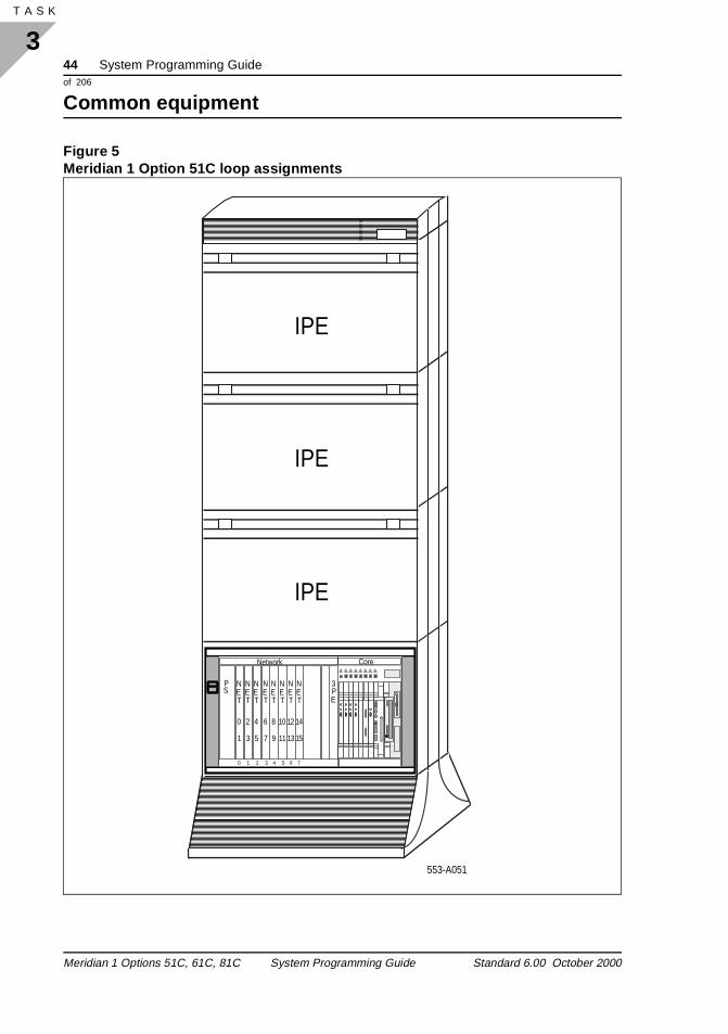
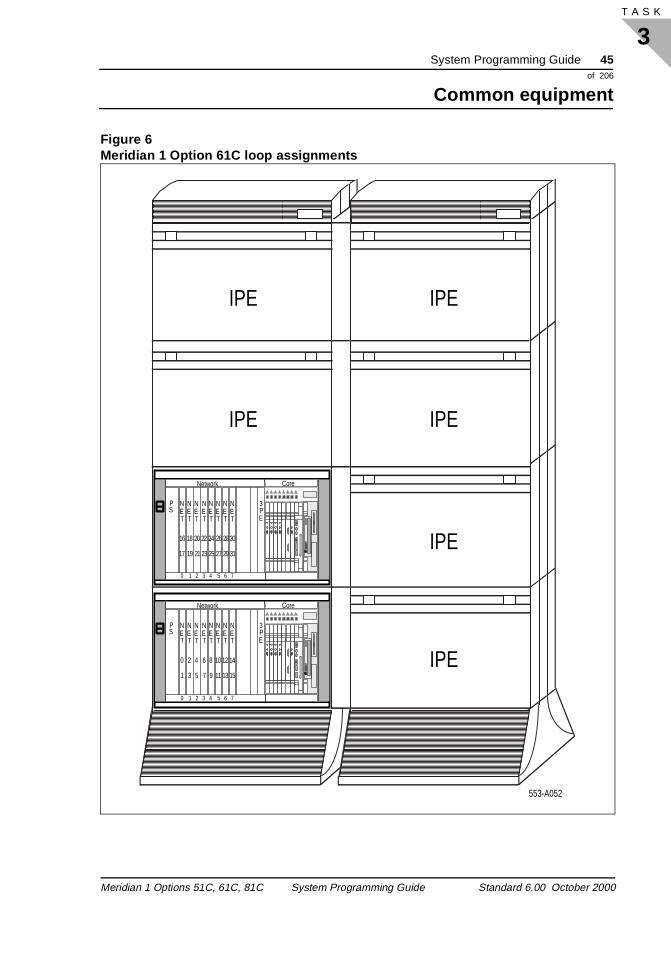
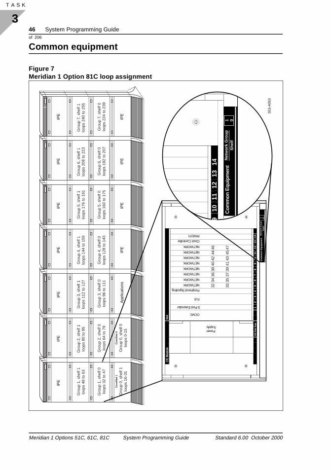
The Conf/TDS cards install in the Core/Net Modules of the Meridia1 Options 51C and 61C and in the Common Equipment Modulesthe Meridian 1 Option 81C. One Conf/TDS card occupies one network card slot. The network card slots are identified by a labellocated at the bottom of the module. Placing a Conf/TDS card intcard slot automatically hardware addresses that card. When you program the Conf/TDS card in the database, your programed addmust match the hardware address so the Core processor can findConf/TDS installed card . The hardware addresses are shown in Figure 5, Figure 6, and Figure 7.
For example, if the Conf/TDS card is located in slot 5 in Shelf 0 oGroup 2, the Conf/TDS card is hardware addressed as loop 64 and 6When you program the Conf/TDS card in the database, with the Xprompt, your response is 64. This programs the TDS part of the cas loop 64 and the Conf part as loop 65.
Service loop identification
Meridian 1 Options 51C, 61C, 81C System Programming Guide Standard 6.00 October 2000
44 System Programming Guideof 206
Common equipment
3T A S K 54
Figure 5Meridian 1 Option 51C loop assignments
Network Core
PS
0 1 2 3 4 5 6 7
NET
NET
NET
NET
NET
NET
NET
NET
2
3
0
1
4
5
6
7
8
9
10
11
12
13
14
15
3PE CP PIIcCNI
ENB
DIS
cCNI
ENB
DIS
cCNI
ENB
DIS
cCNI
ENB
DIS
SYSUTIL
ENB
DIS
HA
IPE
IPE
IPE
553-A051
Meridian 1 Options 51C, 61C, 81C System Programming Guide Standard 6.00 October 2000
System Programming Guide 45of 206
Common equipment
3T A S K
Figure 6Meridian 1 Option 61C loop assignments
Network Core
PS
NET
NET
NET
NET
NET
NET
NET
NET
2
3
0
1
4
5
6
7
8
9
10
11
12
13
14
15
3PE CP PIIcCNI
ENB
DIS
cCNI
ENB
DIS
cCNI
ENB
DIS
cCNI
ENB
DIS
SYSUTIL
ENB
DIS
HA
Network Core
PS
0 1 2 3 4 5 6 7
0 1 2 3 4 5 6 7
NET
NET
NET
NET
NET
NET
NET
NET
26
27
28
29
30
31
20
21
22
23
24
25
16
17
18
19
3PE CP PIIcCNI
ENB
DIS
cCNI
ENB
DIS
cCNI
ENB
DIS
cCNI
ENB
DIS
SYSUTIL
ENB
DIS
HA
IPE
IPE
IPE
IPE
IPE
IPE
553-A052
Meridian 1 Options 51C, 61C, 81C System Programming Guide Standard 6.00 October 2000
46 System Programming Guideof 206
Common equipment
3T A S K 54
Figure 7Meridian 1 Option 81C loop assignment
Gro
up 1
, she
lf 1
loop
s 48
to 6
3
Cor
e/N
et 1
Gro
up 0
, she
lf 1
loop
s 16
-31
Cor
e/N
et 0
Gro
up 0
, she
lf 0
loop
s 0-
15
Gro
up 1
, she
lf 0
loop
s 32
to 4
7
Gro
up 2
, she
lf 1
loop
s 80
to 9
5 G
roup
3, s
helf
1lo
ops
112
to 1
27G
roup
4, s
helf
1lo
ops
144
to 1
59
Gro
up 2
, she
lf 0
loop
s 64
to 7
9G
roup
3, s
helf
0lo
ops
96 to
111
Gro
up 5
, she
lf 1
loop
s 17
6 to
191
Gro
up 5
, she
lf 0
loop
s 16
0 to
175
Gro
up 6
, she
lf 1
loop
s 20
8 to
223
Gro
up 7
, she
lf 1
loop
s 24
0 to
255
Gro
up 6
, she
lf 0
loop
s 19
2 to
207
Gro
up 7
, she
lf 0
loop
s 22
4 to
239
Gro
up 4
, she
lf 0
loop
s 12
8 to
143
IPE
IPE
IPE
IPE
App
licat
ions
IPE
IPE
IPE
IPE
IPE
IPE
IPE
553-
A05
3
Com
mon
Equ
ipm
ent
910
1112
1314
Net
wor
k G
roup
1 0S
helf
CE
Mod
ule
Net
Com
mon
Equ
ipm
ent
12
34
56
78
910
1112
1314
CE
Pw
r Sup
3-Port Extender
Peripheral Signaling
Net
wor
k G
roup
She
lf
Clock Controller
PRI/DTI
FIJI
NETWORK
NETWORK
NETWORK
NETWORK
NETWORK
NETWORK
NETWORK
NETWORK
OCMC
PowerSupply
32 33
34 35
36 37
38 39
40 41
42 43
44 45
46 47
1 0
Meridian 1 Options 51C, 61C, 81C System Programming Guide Standard 6.00 October 2000
System Programming Guide 47of 206
Common equipment
3T A S K
ith ion e the
ated the
ide
ture
Remote peripheral equipment loopsIn addition to supporting peripheral equipment cards collocated wthe common equipment, Meridian 1 systems can support RemotePeripheral Equipment (RPE). Depending on the type of transmissmedia required between the host site (Meridian 1 system) and thremote site and the type of peripheral equipment cards selected,following RPE products are supported:
� Remote Peripheral Equipment
� Carrier Remote IPE
� Fiber Remote IPE
� Fiber Remote Multi-IPE
Each of these remote products allow the peripheral cards to be locremotely from the host system. In the case of Remote PeripheralEquipment (RPE) and Carrier Remote IPE, these products allow system network interface to be converted and transported across commonly used T1 or E1 digital facilities including digital microwave radio.
The Fiber Remote IPE and Fiber Remote Multi-IPE products provthe same network conversion requirements, but transport fiber facilities instead of T1 or E1.
All of these products offer the remote users the same level of feafunctionality provided to the local users. Essentially, these remoteproducts allow the remote peripherals to function as if they were collocated with the local peripheral equipment.
For more information, refer to Remote Peripheral Equipment: Description, Installation, and Testing (553-2601-200).
Meridian 1 Options 51C, 61C, 81C System Programming Guide Standard 6.00 October 2000
48 System Programming Guideof 206
Common equipment
3T A S K 54
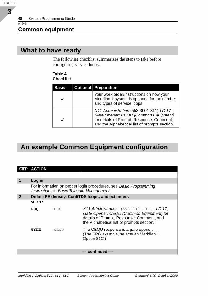
The following checklist summarizes the steps to take before configuring service loops.
What to have ready
Table 4 Checklist
Basic Optional Preparation
✓Your work order/instructions on how your Meridian 1 system is optioned for the number and types of service loops.
✓
X11 Administration (553-3001-311) LD 17, Gate Opener: CEQU (Common Equipment) for details of Prompt, Response, Comment, and the Alphabetical list of prompts section.
An example Common Equipment configuration
STEP ACTION
1 Log inFor information on proper login procedures, see Basic Programming Instructions in Basic Telecom Management.
2 Define PE density, Conf/TDS loops, and extenders>LD 17
REQ CHG X11 Administration (553-3001-311) LD 17, Gate Opener: CEQU (Common Equipment) for details of Prompt, Response, Comment, and the Alphabetical list of prompts section.
TYPE CEQU The CEQU response is a gate opener.(The SPG example, selects an Meridian 1 Option 81C.)
— continued —
Meridian 1 Options 51C, 61C, 81C System Programming Guide Standard 6.00 October 2000
System Programming Guide 49of 206
Common equipment
3T A S K
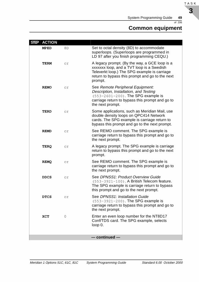
MPED 8D Set to octal density (8D) to accommodate superloops. (Superloops are programmed in LD 97 after you finish programming CEQU.)
TERM cr A legacy prompt. (By the way, a GCE loop is a xxxxxxx loop, and a TVT loop is a Swedish Televerkt loop.) The SPG example is carriage return to bypass this prompt and go to the next prompt.
REMO cr See Remote Peripheral Equipment: Description, Installation, and Testing (553-2601-200) . The SPG example is carriage return to bypass this prompt and go to the next prompt.
TERD cr Some applications, such as Meridian Mail, use double density loops on QPC414 Network cards. The SPG example is carriage return to bypass this prompt and go to the next prompt.
REMD cr See REMO comment. The SPG example is carriage return to bypass this prompt and go to the next prompt.
TERQ cr A legacy prompt. The SPG example is carriage return to bypass this prompt and go to the next prompt.
REMQ cr See REMO comment. The SPG example is carriage return to bypass this prompt and go to the next prompt.
DDCS cr See DPNSS1: Product Overview Guide (553-3921-100) . A British Telecom feature. The SPG example is carriage return to bypass this prompt and go to the next prompt.
DTCS cr See DPNSS1: Installation Guide (553-3921-200) . The SPG example is carriage return to bypass this prompt and go to the next prompt.
XCT 0 Enter an even loop number for the NT8D17 Conf/TDS card. The SPG example, selects loop 0.
— continued —
STEP ACTION
Meridian 1 Options 51C, 61C, 81C System Programming Guide Standard 6.00 October 2000
50 System Programming Guideof 206
Common equipment
3T A S K 54
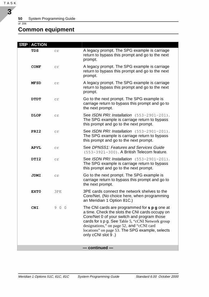
TDS cr A legacy prompt. The SPG example is carriage return to bypass this prompt and go to the next prompt.
CONF cr A legacy prompt. The SPG example is carriage return to bypass this prompt and go to the next prompt.
MFSD cr A legacy prompt. The SPG example is carriage return to bypass this prompt and go to the next prompt.
DTDT cr Go to the next prompt. The SPG example is carriage return to bypass this prompt and go to the next prompt.
DLOP cr See ISDN PRI: Installation (553-2901-201) . The SPG example is carriage return to bypass this prompt and go to the next prompt.
PRI2 cr See ISDN PRI: Installation (553-2901-201) . The SPG example is carriage return to bypass this prompt and go to the next prompt.
APVL cr See DPNSS1: Features and Services Guide (553-3921-300) . A British Telecom feature.
DTI2 cr See ISDN PRI: Installation (553-2901-201) . The SPG example is carriage return to bypass this prompt and go to the next prompt.
JDMI cr Go to the next prompt. The SPG example is carriage return to bypass this prompt and go to the next prompt.
EXT0 3PE 3PE cards connect the network shelves to the Core/Net. (No choice here, when programming an Meridian 1 Option 81C.)
CNI 9 0 0 The CNI cards are programmed for s p g one at a time. Check the slots the CNI cards occupy on Core/Net 0 of your switch and program those cards for s p g. See Table 5, “cCNI Network group designations,” on page 52, and “cCNI card locations” on page 53. The SPG example, selects only cCNI slot 9 .)
— continued —
STEP ACTION
Meridian 1 Options 51C, 61C, 81C System Programming Guide Standard 6.00 October 2000
System Programming Guide 51of 206
Common equipment
3T A S K
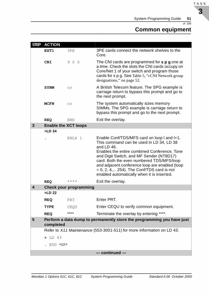
EXT1 3PE 3PE cards connect the network shelves to the Core.
CNI 9 0 0 The CNI cards are programmed for s p g one at a time. Check the slots the CNI cards occupy on Core/Net 1 of your switch and program those cards for s p g. See Table 5, “cCNI Network group designations,” on page 52.
SYNM cr A British Telecom feature. The SPG example is carriage return to bypass this prompt and go to the next prompt.
MCFN cr The system automatically sizes memory SIMMs. The SPG example is carriage return to bypass this prompt and go to the next prompt.
REQ END Exit the overlay. 3 Enable the XCT loops
>LD 34
. ENLX l Enable Conf/TDS/MFS card on loop l and l+1.This command can be used in LD 34, LD 38 and LD 46.Enables the entire combined Conference, Tone and Digit Switch, and MF Sender (NT8D17) card. Both the even numbered TDS/MFS/loop and adjacent conference loop are enabled (loop = 0, 2, 4,... 254). The Conf/TDS card is not enabled automatically when it is inserted.
REQ **** Exit the overlay. 4 Check your programming
>LD 22
REQ PRT Enter PRT.
TYPE CEQU Enter CEQU to verify common equipment.
REQ **** Terminate the overlay by entering ****.5 Perform a data dump to permanently store the programming you have just
completedRefer to X11 Maintenance (553-3001-511) for more information on LD 43.
> LD 43
. EDD <cr>
— continued —
STEP ACTION
Meridian 1 Options 51C, 61C, 81C System Programming Guide Standard 6.00 October 2000
52 System Programming Guideof 206
Common equipment
3T A S K 54
6 Verify that the data dump was successfulSystem response:
Database backup Complete!
For any other system response, contact your system supplier.7 Terminate this programming session
Log off.
>LOGO
8 You have completed the programming required to configure a history or traffic file
END
Table 5cCNI Network group designations
cCNI card slot
cCNI card port
3PE Termination Panel label
Connected to Network
group
c9 0 N/A (factory installed directly to the Core/Net backplane)
0
c9 1 Port 9-1 1
c10 0 Port 10-0 2
c10 1 Port 10-1 3
c11 0 Port 11-0 4
c11 1 Port 11-1 5
c12 0 Port 12-0 6
c12 1 Port 12-1 7
STEP ACTION
Meridian 1 Options 51C, 61C, 81C System Programming Guide Standard 6.00 October 2000
System Programming Guide 53of 206
Common equipment
3T A S K
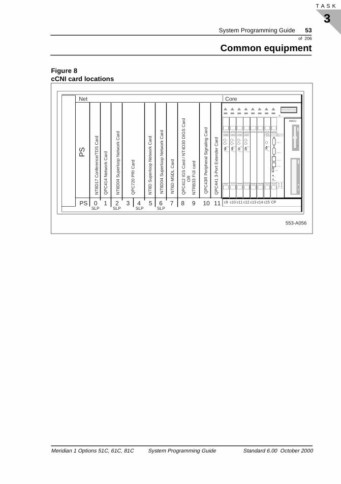
Figure 8cCNI card locations
PS
Net
Enb
Dis
SYS UTIL
LLAN 1
USB
INIT
RESETALRM SPKR
HDD PWR
CCOM 2
cCNI
A
B
Enb
Dis
cCNI
A
B
Enb
Dis
cCNI
A
B
Enb
Dis
cCNI
A
B
Enb
Dis
LLAN 2
CCOM 1
CPPII
MMDU
553-A056
NT
8D17
Con
fere
nce/
TD
S C
ard
QP
C41
4 N
etw
ork
Car
d
NT
8D04
Sup
erlo
op N
etw
ork
Car
d
QP
C72
0 P
RI C
ard
NT
8D S
uper
loop
Net
wor
k C
ard
SLP SLP SLP SLP
NT
8D04
Sup
erlo
op N
etw
ork
Car
d
NT
6D M
SD
L C
ard
QP
C43
R P
erip
hera
l Sig
nalin
g C
ard
QP
C44
1 3-
Por
t Ext
ende
r C
ard
Core
OR
QP
C41
2 IG
S C
ard
/ NT
4D30
DIG
S C
ard
NT
RB
33 F
IJI c
ard
PS 0 1 2 3 4 5 6 7 8 9 10 11 c9 c10 c11 c12 c13 c14 c15 CP
Meridian 1 Options 51C, 61C, 81C System Programming Guide Standard 6.00 October 2000
54 System Programming Guideof 206
Common equipment
3T A S K 54
Meridian 1 Options 51C, 61C, 81C System Programming Guide Standard 6.00 October 2000
System Programming Guide 55of 206
IPE and Superloop configuration
4T A S K
ing
to
to ps
ber
IPE and Superloop configurationLoops
Task 4Task numberBasic configuration
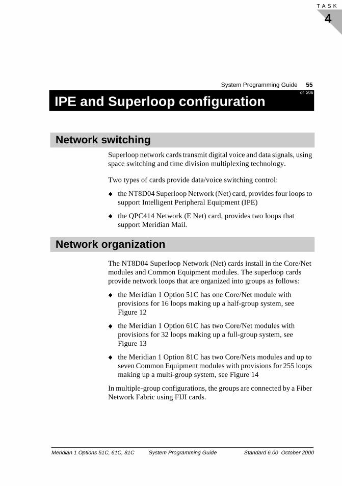
Superloop network cards transmit digital voice and data signals, usspace switching and time division multiplexing technology.
Two types of cards provide data/voice switching control:
� the NT8D04 Superloop Network (Net) card, provides four loopssupport Intelligent Peripheral Equipment (IPE)
� the QPC414 Network (E Net) card, provides two loops that support Meridian Mail.
The NT8D04 Superloop Network (Net) cards install in the Core/Net modules and Common Equipment modules. The superloop cardsprovide network loops that are organized into groups as follows:
� the Meridian 1 Option 51C has one Core/Net module with provisions for 16 loops making up a half-group system, see Figure 12
� the Meridian 1 Option 61C has two Core/Net modules with provisions for 32 loops making up a full-group system, see Figure 13
� the Meridian 1 Option 81C has two Core/Nets modules and upseven Common Equipment modules with provisions for 255 loomaking up a multi-group system, see Figure 14
In multiple-group configurations, the groups are connected by a FiNetwork Fabric using FIJI cards.
Network switching
Network organization
Meridian 1 Options 51C, 61C, 81C System Programming Guide Standard 6.00 October 2000
56 System Programming Guideof 206
IPE and Superloop configuration
4T A S K 66
of top tom
d on.
p
2 of he d
PRI , 7
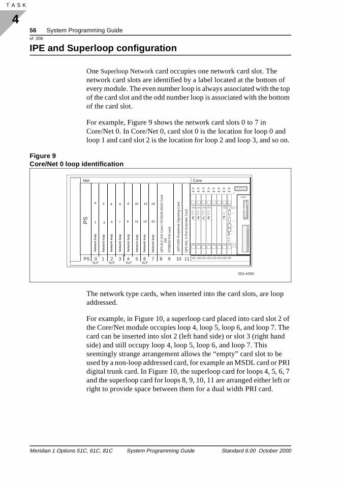
One Superloop Network card occupies one network card slot. The network card slots are identified by a label located at the bottom every module. The even number loop is always associated with theof the card slot and the odd number loop is associated with the botof the card slot.
For example, Figure 9 shows the network card slots 0 to 7 in Core/Net 0. In Core/Net 0, card slot 0 is the location for loop 0 anloop 1 and card slot 2 is the location for loop 2 and loop 3, and so
Figure 9Core/Net 0 loop identification
The network type cards, when inserted into the card slots, are looaddressed.
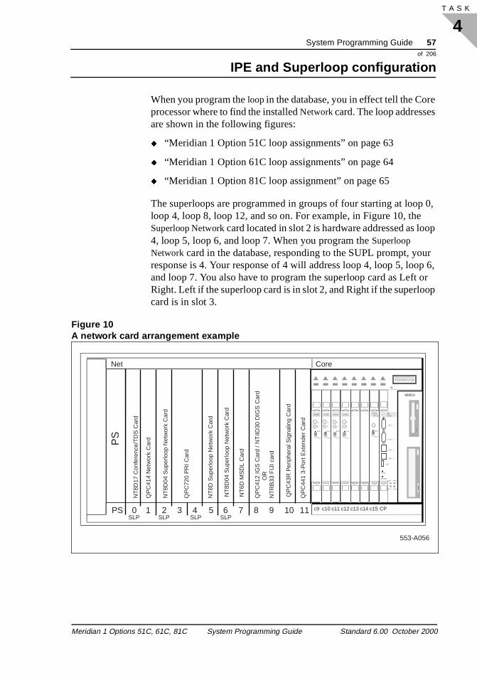
For example, in Figure 10, a superloop card placed into card slot the Core/Net module occupies loop 4, loop 5, loop 6, and loop 7. Tcard can be inserted into slot 2 (left hand side) or slot 3 (right hanside) and still occupy loop 4, loop 5, loop 6, and loop 7. This seemingly strange arrangement allows the “empty” card slot to beused by a non-loop addressed card, for example an MSDL card ordigital trunk card. In Figure 10, the superloop card for loops 4, 5, 6and the superloop card for loops 8, 9, 10, 11 are arranged either left or right to provide space between them for a dual width PRI card.
PS
Net
Enb
Dis
SYS UTIL
LLAN 1
USB
INIT
RESETALRM SPKR
HDD PWR
CCOM 2
cCNI
A
B
Enb
Dis
cCNI
A
B
Enb
Dis
cCNI
A
B
Enb
Dis
cCNI
A
B
Enb
Dis
LLAN 2
CCOM 1
CPPII
MMDU
553-A055
SLP SLP SLP SLP
QP
C43
R P
erip
hera
l Sig
nalin
g C
ard
QP
C44
1 3-
Por
t Ext
ende
r C
ard
Core
OR
QP
C41
2 IG
S C
ard
/ NT
4D30
DIG
S C
ard
NT
RB
33 F
IJI c
ard
PS 0 1 2 3 4 5 6 7 8 9 10 11
Net
wor
k lo
op
Net
wor
k lo
op
Net
wor
k lo
op
Net
wor
k lo
op
Net
wor
k lo
op
Net
wor
k lo
op
Net
wor
k lo
op
Net
wor
k lo
op
0
1
2
3
4
5
6
7
8
9
10
11
12
13
14
15
c9 c10 c11 c12 c13 c14 c15 CP
Meridian 1 Options 51C, 61C, 81C System Programming Guide Standard 6.00 October 2000
System Programming Guide 57of 206
IPE and Superloop configuration
4T A S K
e
0, op
ur p 6, or op
When you program the loop in the database, you in effect tell the Corprocessor where to find the installed Network card. The loop addresses are shown in the following figures:
� “Meridian 1 Option 51C loop assignments” on page 63
� “Meridian 1 Option 61C loop assignments” on page 64
� “Meridian 1 Option 81C loop assignment” on page 65
The superloops are programmed in groups of four starting at looploop 4, loop 8, loop 12, and so on. For example, in Figure 10, theSuperloop Network card located in slot 2 is hardware addressed as lo4, loop 5, loop 6, and loop 7. When you program the Superloop Network card in the database, responding to the SUPL prompt, yoresponse is 4. Your response of 4 will address loop 4, loop 5, looand loop 7. You also have to program the superloop card as Left Right. Left if the superloop card is in slot 2, and Right if the superlocard is in slot 3.
Figure 10A network card arrangement example
PS
Net
Enb
Dis
SYS UTIL
LLAN 1
USB
INIT
RESETALRM SPKR
HDD PWR
CCOM 2
cCNI
A
B
Enb
Dis
cCNI
A
B
Enb
Dis
cCNI
A
B
Enb
Dis
cCNI
A
B
Enb
Dis
LLAN 2
CCOM 1
CPPII
MMDU
553-A056
NT
8D17
Con
fere
nce/
TD
S C
ard
QP
C41
4 N
etw
ork
Car
d
NT
8D04
Sup
erlo
op N
etw
ork
Car
d
QP
C72
0 P
RI C
ard
NT
8D S
uper
loop
Net
wor
k C
ard
SLP SLP SLP SLP
NT
8D04
Sup
erlo
op N
etw
ork
Car
d
NT
6D M
SD
L C
ard
QP
C43
R P
erip
hera
l Sig
nalin
g C
ard
QP
C44
1 3-
Por
t Ext
ende
r C
ard
Core
OR
QP
C41
2 IG
S C
ard
/ NT
4D30
DIG
S C
ard
NT
RB
33 F
IJI c
ard
PS 0 1 2 3 4 5 6 7 8 9 10 11 c9 c10 c11 c12 c13 c14 c15 CP
Meridian 1 Options 51C, 61C, 81C System Programming Guide Standard 6.00 October 2000
58 System Programming Guideof 206
IPE and Superloop configuration
4T A S K 66
s
bers e
es 14 lots
s
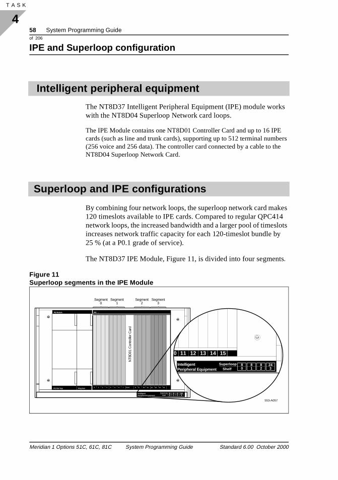
The NT8D37 Intelligent Peripheral Equipment (IPE) module workwith the NT8D04 Superloop Network card loops.
The IPE Module contains one NT8D01 Controller Card and up to 16 IPEcards (such as line and trunk cards), supporting up to 512 terminal num(256 voice and 256 data). The controller card connected by a cable to thNT8D04 Superloop Network Card.
By combining four network loops, the superloop network card mak120 timeslots available to IPE cards. Compared to regular QPC4network loops, the increased bandwidth and a larger pool of timesincreases network traffic capacity for each 120-timeslot bundle by25 % (at a P0.1 grade of service).
The NT8D37 IPE Module, Figure 11, is divided into four segment.
Figure 11Superloop segments in the IPE Module
Intelligent peripheral equipment
Superloop and IPE configurations
553-A057
IntelligentPeripheral Equipment
0 11 12 13 14 15
Superloop 80Shelf
81
82
243
IntelligentPeripheral Equipment
Superloop
Shelf
IPEPE Module
PE Pwr Sup Rng Gen
NT8
D01
Con
trolle
r Car
d
Segment0
Segment1
Segment2
Segment3
0 2 3 4 5 6 7 Cont 9 11 12 13 151 8 1410
80
81
82
243
Meridian 1 Options 51C, 61C, 81C System Programming Guide Standard 6.00 October 2000
System Programming Guide 59of 206
IPE and Superloop configuration
4T A S K
e of
ume 4
,
A superloop connects to one segment or up to as many as eight segments. (Eight segments require two IPE modules.)
One superloop connected to one segment can handle a high volumtelephone traffic. For example, out of a possible number of 128 telephones, 120 telephones can be in use at any one time.
One superloop connected to eight segments can handle a low volof telephone traffic. For example, out of a possible number of 102telephones, 120 telephones can be in use at any one time.
The flexibility of superloop and segment combinations allow cost effective provisioning for different telephone traffic situations.
For example, in Figure 11, segments 0, 1, and 2 are connected tosuperloop 8. This gives a low traffic capability to superloop 8. Segment 3 is connected to loop 24 giving high traffic capability.
For a detailed description of superloop-to-segment configurationssee Meridian 1 system engineering (553-3001-151).
The following checklist summarizes the steps to take before configuring Superloops and controllers.
What to have ready
Table 6 Checklist
Basic Optional Preparation
✓Your work order/instructions on how your Meridian 1 system is optioned for network card slot for the superloop cards.
✓
X11 Administration (553-3001-311) LD 97, Gate Opener: XPE (Extended Peripheral Equipment shelf data block), SUPL (Superloop parameters data block) for details of Prompt, Response, Comment, and the Alphabetical list of prompts section.
Meridian 1 Options 51C, 61C, 81C System Programming Guide Standard 6.00 October 2000
60 System Programming Guideof 206
IPE and Superloop configuration
4T A S K 66
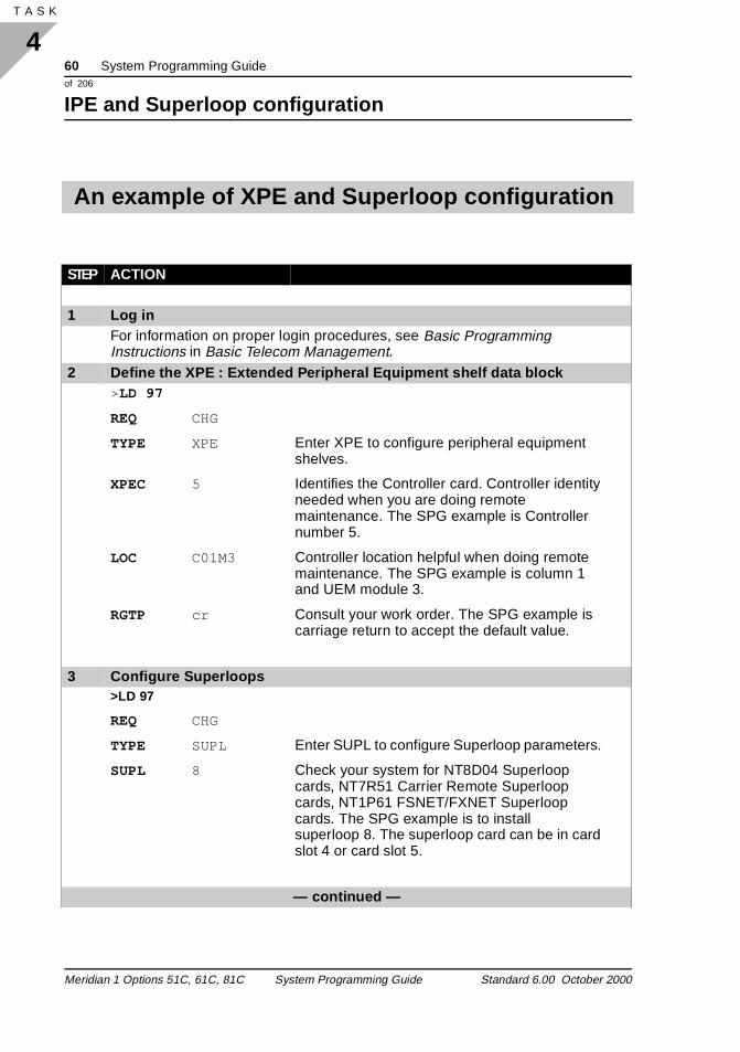
An example of XPE and Superloop configuration
STEP ACTION
1 Log inFor information on proper login procedures, see Basic Programming Instructions in Basic Telecom Management.
2 Define the XPE : Extended Peripheral Equipment shelf data block>LD 97
REQ CHG
TYPE XPE Enter XPE to configure peripheral equipment shelves.
XPEC 5 Identifies the Controller card. Controller identity needed when you are doing remote maintenance. The SPG example is Controller number 5.
LOC C01M3 Controller location helpful when doing remote maintenance. The SPG example is column 1 and UEM module 3.
RGTP cr Consult your work order. The SPG example is carriage return to accept the default value.
3 Configure Superloops>LD 97
REQ CHG
TYPE SUPL Enter SUPL to configure Superloop parameters.
SUPL 8 Check your system for NT8D04 Superloop cards, NT7R51 Carrier Remote Superloop cards, NT1P61 FSNET/FXNET Superloop cards. The SPG example is to install superloop 8. The superloop card can be in card slot 4 or card slot 5.
— continued —
Meridian 1 Options 51C, 61C, 81C System Programming Guide Standard 6.00 October 2000
System Programming Guide 61of 206
IPE and Superloop configuration
4T A S K
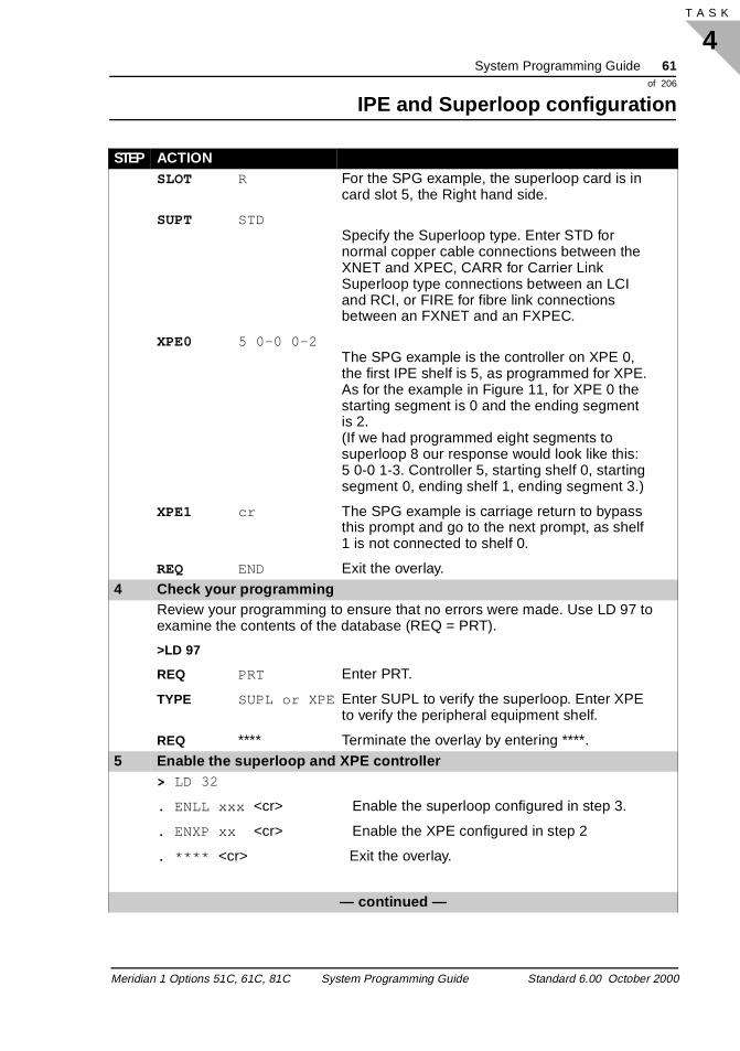
SLOT R For the SPG example, the superloop card is in card slot 5, the Right hand side.
SUPT STDSpecify the Superloop type. Enter STD for normal copper cable connections between the XNET and XPEC, CARR for Carrier Link Superloop type connections between an LCI and RCI, or FIRE for fibre link connections between an FXNET and an FXPEC.
XPE0 5 0-0 0-2The SPG example is the controller on XPE 0, the first IPE shelf is 5, as programmed for XPE. As for the example in Figure 11, for XPE 0 the starting segment is 0 and the ending segment is 2.(If we had programmed eight segments to superloop 8 our response would look like this: 5 0-0 1-3. Controller 5, starting shelf 0, starting segment 0, ending shelf 1, ending segment 3.)
XPE1 cr The SPG example is carriage return to bypass this prompt and go to the next prompt, as shelf 1 is not connected to shelf 0.
REQ END Exit the overlay. 4 Check your programming
Review your programming to ensure that no errors were made. Use LD 97 to examine the contents of the database (REQ = PRT).
>LD 97
REQ PRT Enter PRT.
TYPE SUPL or XPE Enter SUPL to verify the superloop. Enter XPE to verify the peripheral equipment shelf.
REQ **** Terminate the overlay by entering ****.5 Enable the superloop and XPE controller
> LD 32
. ENLL xxx <cr> Enable the superloop configured in step 3.
. ENXP xx <cr> Enable the XPE configured in step 2
. **** <cr> Exit the overlay.
— continued —
STEP ACTION
Meridian 1 Options 51C, 61C, 81C System Programming Guide Standard 6.00 October 2000
62 System Programming Guideof 206
IPE and Superloop configuration
4T A S K 66
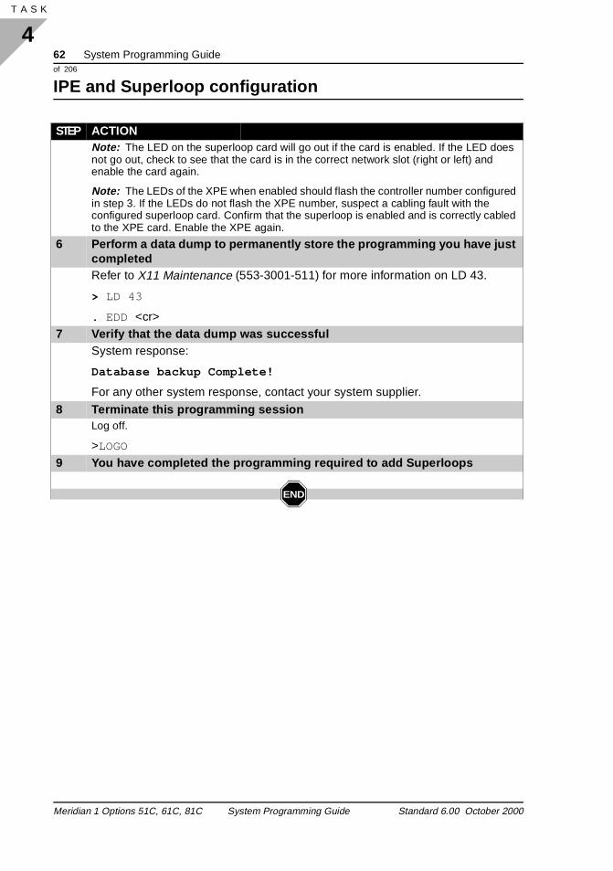
Note: The LED on the superloop card will go out if the card is enabled. If the LED does not go out, check to see that the card is in the correct network slot (right or left) and enable the card again.
Note: The LEDs of the XPE when enabled should flash the controller number configured in step 3. If the LEDs do not flash the XPE number, suspect a cabling fault with the configured superloop card. Confirm that the superloop is enabled and is correctly cabled to the XPE card. Enable the XPE again.
6 Perform a data dump to permanently store the programming you have just completedRefer to X11 Maintenance (553-3001-511) for more information on LD 43.
> LD 43
. EDD <cr>7 Verify that the data dump was successful
System response:
Database backup Complete!
For any other system response, contact your system supplier.
8 Terminate this programming sessionLog off.
>LOGO
9 You have completed the programming required to add Superloops
END
STEP ACTION
Meridian 1 Options 51C, 61C, 81C System Programming Guide Standard 6.00 October 2000
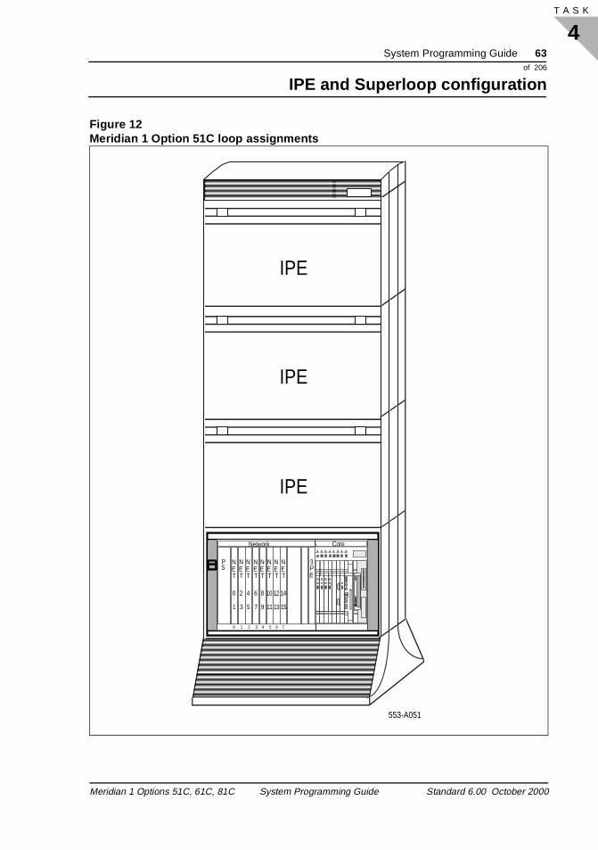
System Programming Guide 63of 206
IPE and Superloop configuration
4T A S K
Figure 12Meridian 1 Option 51C loop assignments
Network Core
PS
0 1 2 3 4 5 6 7
NET
NET
NET
NET
NET
NET
NET
NET
2
3
0
1
4
5
6
7
8
9
10
11
12
13
14
15
3PE CP PIIcCNI
ENB
DIS
cCNI
ENB
DIS
cCNI
ENB
DIS
cCNI
ENB
DIS
SYSUTIL
ENB
DIS
HA
IPE
IPE
IPE
553-A051
Meridian 1 Options 51C, 61C, 81C System Programming Guide Standard 6.00 October 2000
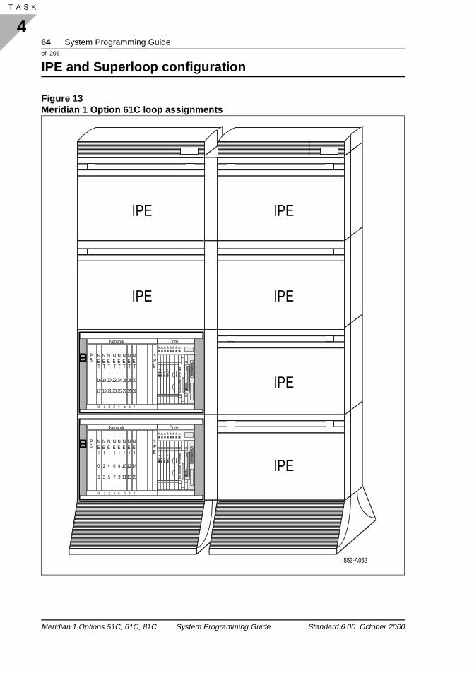
64 System Programming Guideof 206
IPE and Superloop configuration
4T A S K 66
Figure 13Meridian 1 Option 61C loop assignments
Network Core
PS
NET
NET
NET
NET
NET
NET
NET
NET
2
3
0
1
4
5
6
7
8
9
10
11
12
13
14
15
3PE CP PIIcCNI
ENB
DIS
cCNI
ENB
DIS
cCNI
ENB
DIS
cCNI
ENB
DIS
SYSUTIL
ENB
DIS
HA
Network Core
PS
0 1 2 3 4 5 6 7
0 1 2 3 4 5 6 7
NET
NET
NET
NET
NET
NET
NET
NET
26
27
28
29
30
31
20
21
22
23
24
25
16
17
18
19
3PE CP PIIcCNI
ENB
DIS
cCNI
ENB
DIS
cCNI
ENB
DIS
cCNI
ENB
DIS
SYSUTIL
ENB
DIS
HA
IPE
IPE
IPE
IPE
IPE
IPE
553-A052
Meridian 1 Options 51C, 61C, 81C System Programming Guide Standard 6.00 October 2000
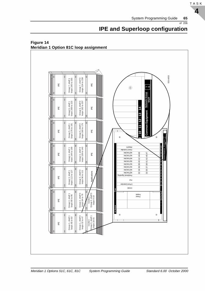
System Programming Guide 65of 206
IPE and Superloop configuration
4T A S K
Figure 14Meridian 1 Option 81C loop assignment
Gro
up 1
, she
lf 1
loop
s 48
to 6
3
Cor
e/N
et 1
Gro
up 0
, she
lf 1
loop
s 16
-31
Cor
e/N
et 0
Gro
up 0
, she
lf 0
loop
s 0-
15
Gro
up 1
, she
lf 0
loop
s 32
to 4
7
Gro
up 2
, she
lf 1
loop
s 80
to 9
5 G
roup
3, s
helf
1lo
ops
112
to 1
27G
roup
4, s
helf
1lo
ops
144
to 1
59
Gro
up 2
, she
lf 0
loop
s 64
to 7
9G
roup
3, s
helf
0lo
ops
96 to
111
Gro
up 5
, she
lf 1
loop
s 17
6 to
191
Gro
up 5
, she
lf 0
loop
s 16
0 to
175
Gro
up 6
, she
lf 1
loop
s 20
8 to
223
Gro
up 7
, she
lf 1
loop
s 24
0 to
255
Gro
up 6
, she
lf 0
loop
s 19
2 to
207
Gro
up 7
, she
lf 0
loop
s 22
4 to
239
Gro
up 4
, she
lf 0
loop
s 12
8 to
143
IPE
IPE
IPE
IPE
App
licat
ions
IPE
IPE
IPE
IPE
IPE
IPE
IPE
553-
A05
3
Com
mon
Equ
ipm
ent
910
1112
1314
Net
wor
k G
roup
1 0S
helf
CE
Mod
ule
Net
Com
mon
Equ
ipm
ent
12
34
56
78
910
1112
1314
CE
Pw
r Sup
3-Port Extender
Peripheral Signaling
Net
wor
k G
roup
She
lf
Clock Controller
PRI/DTI
FIJI
NETWORK
NETWORK
NETWORK
NETWORK
NETWORK
NETWORK
NETWORK
NETWORK
OCMC
PowerSupply
32 33
34 35
36 37
38 39
40 41
42 43
44 45
46 47
1 0
Meridian 1 Options 51C, 61C, 81C System Programming Guide Standard 6.00 October 2000
66 System Programming Guideof 206
IPE and Superloop configuration
4T A S K 66
Meridian 1 Options 51C, 61C, 81C System Programming Guide Standard 6.00 October 2000
System Programming Guide 67of 206
Setting up system parameters
5T A S K
ses s
is
er
or
set rd,
to
Setting up system parametersSystem parameters
Task 5
Basic configuration
You can set system parameters that control how the Meridian 1 usignal companding, how it handles timeslot faults, and how it usesignaling such as switch-hook flashes and pulse dialing.
The information you enter during this stage of basic configurationdescribed in detail below. Procedures for entering this information are provided later in this chapter.
Note: Attempts to readjust the system parameters without detailed system knowledge could cause severe disruption in service.
To use the µ-Law international companding law, enter YES at theINTN prompt. To use the A-law international companding law, entNO.
To set the maintenance threshold for timeslot continuity faults, respond to the CONT prompt. To set the maintenance threshold fcyclic redundancy check (CRC) continuity faults, respond to the CRCF prompt.
To set the switchhook flash time, respond to the FLSH prompt. Tothe off-hook validation timer for an extended flexible analog line carespond to the TOHY prompt.
To set the minimum time allowed for pulse dialing, respond to theTDP prompt. To set the maximum time for pulse dialing, respondthe TID prompt.
Purpose
System parameters
Meridian 1 Options 51C, 61C, 81C System Programming Guide Standard 6.00 October 2000
68 System Programming Guideof 206
Setting up system parameters
5T A S K 76
n
tive
he
f a
ine vels
ect
The Meridian 1 compensates for line quality and line characteristics to provide uniform service over a variety of trunk and line types. Iorder to match itself to a particular type of trunk or line, the Meridian 1 needs information about the line.
To configure an IPE, enter loss and level information for each trunk. Loss planning can be complex, and is usually done before the Meridian 1 is installed. For details, see International Loss and Level Plan (553-2201-181).
Selecting tablesWhen creating a customized loss and level table, or disabling an actable, enter a second-level administration password.
To select the North American transmission plan for Central Officetrunks (COT), enter YES at the NATP prompt. If you are not using tNorth American transmission plan, enter NO.
Enter the B34 table type at the TTYP prompt. Enter the number opredefined table, if this table is to be used, at the TNUM prompt.
Trunk transmit and receive levels Central office trunks Enter receive and transmit levels for the central office trunk short-lclass of service at the COTS prompt. Enter receive and transmit lefor the central office trunk long-line class of service at the COTL prompt.
Direct inward and outward dial trunks Enter receive and transmit levels for the direct inward dial and diroutward dial short-line class of service at the DIDS prompt.
Loss plans
Meridian 1 Options 51C, 61C, 81C System Programming Guide Standard 6.00 October 2000
System Programming Guide 69of 206
Setting up system parameters
5T A S K
and f the
and f the
line the
TIE trunks Enter receive and transmit levels for the TIE trunk two-wire compensated class of service at the T2WT prompt. Enter receivetransmit levels for the TIE trunk two-wire uncompensated class oservice at the T2WN prompt. Enter receive and transmit levels for TIE trunk two-wire via-network-loss (VNL) class of service at the T2WV prompt.
Enter receive and transmit levels for the TIE trunk four-wire compensated class of service at the T4WT prompt. Enter receivetransmit levels for the TIE trunk four-wire uncompensated class oservice at the T4WN prompt. Enter receive and transmit levels for TIE trunk four-wire via-network-loss (VNL) class of service at the T4WV prompt.
Paging trunks Enter a coded transmit relative input/output level for paging trunks atthe PAGT prompt.
Recorded announcement trunks Enter a coded receive relative input/output level for recorded announcement trunks at the RANR prompt.
Analog line cards If your Meridian 1 has analog line cards installed, enter the analog card unit short line class of service transmit and receive levels at ALUS prompt. Enter the long line class of service transmit and receive levels at the ALUL prompt.
Meridian 1 Options 51C, 61C, 81C System Programming Guide Standard 6.00 October 2000
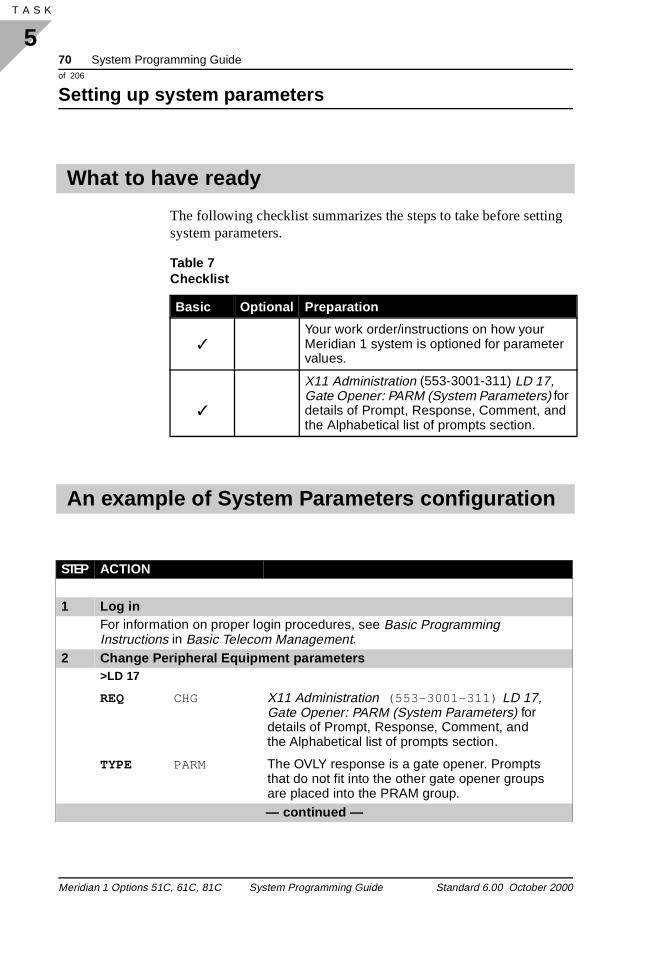
70 System Programming Guideof 206
Setting up system parameters
5T A S K 76
ng
The following checklist summarizes the steps to take before settisystem parameters.What to have ready
Table 7 Checklist
Basic Optional Preparation
✓Your work order/instructions on how your Meridian 1 system is optioned for parameter values.
✓
X11 Administration (553-3001-311) LD 17, Gate Opener: PARM (System Parameters) for details of Prompt, Response, Comment, and the Alphabetical list of prompts section.
An example of System Parameters configuration
STEP ACTION
1 Log inFor information on proper login procedures, see Basic Programming Instructions in Basic Telecom Management.
2 Change Peripheral Equipment parameters>LD 17
REQ CHG X11 Administration (553-3001-311) LD 17, Gate Opener: PARM (System Parameters) for details of Prompt, Response, Comment, and the Alphabetical list of prompts section.
TYPE PARM The OVLY response is a gate opener. Prompts that do not fit into the other gate opener groups are placed into the PRAM group.— continued —
Meridian 1 Options 51C, 61C, 81C System Programming Guide Standard 6.00 October 2000
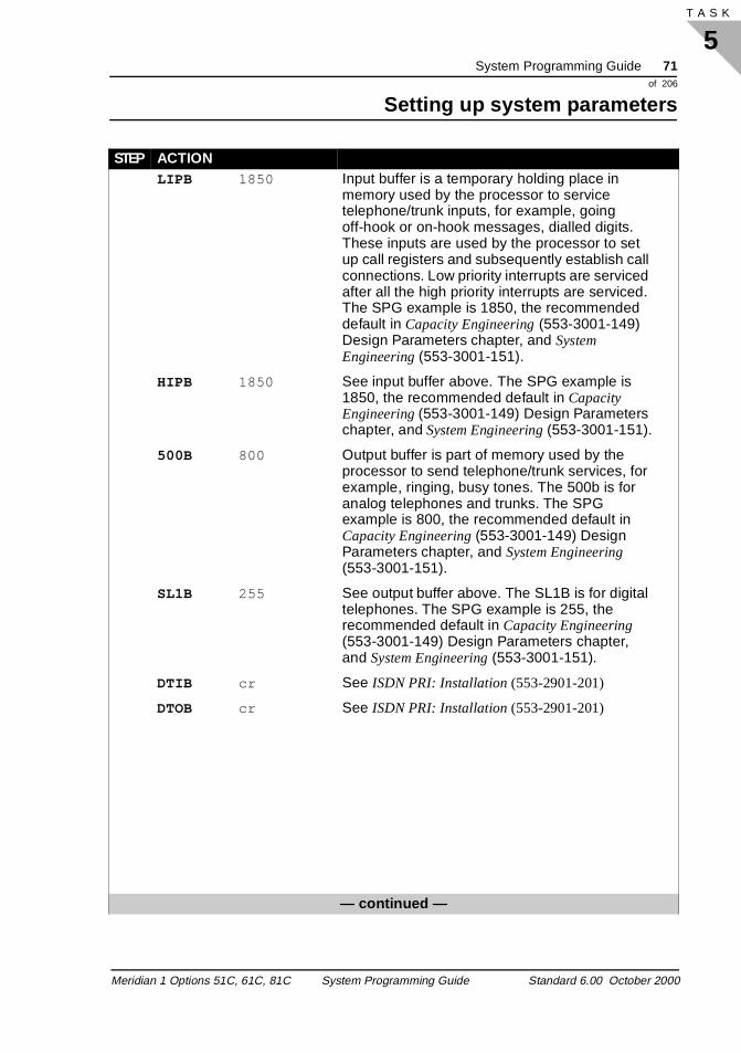
System Programming Guide 71of 206
Setting up system parameters
5T A S K
LIPB 1850 Input buffer is a temporary holding place in memory used by the processor to service telephone/trunk inputs, for example, going off-hook or on-hook messages, dialled digits. These inputs are used by the processor to set up call registers and subsequently establish call connections. Low priority interrupts are serviced after all the high priority interrupts are serviced. The SPG example is 1850, the recommended default in Capacity Engineering (553-3001-149) Design Parameters chapter, and System Engineering (553-3001-151).
HIPB 1850 See input buffer above. The SPG example is 1850, the recommended default in Capacity Engineering (553-3001-149) Design Parameters chapter, and System Engineering (553-3001-151).
500B 800 Output buffer is part of memory used by the processor to send telephone/trunk services, for example, ringing, busy tones. The 500b is for analog telephones and trunks. The SPG example is 800, the recommended default in Capacity Engineering (553-3001-149) Design Parameters chapter, and System Engineering (553-3001-151).
SL1B 255 See output buffer above. The SL1B is for digital telephones. The SPG example is 255, the recommended default in Capacity Engineering (553-3001-149) Design Parameters chapter, and System Engineering (553-3001-151).
DTIB cr See ISDN PRI: Installation (553-2901-201)
DTOB cr See ISDN PRI: Installation (553-2901-201)
— continued —
STEP ACTION
Meridian 1 Options 51C, 61C, 81C System Programming Guide Standard 6.00 October 2000
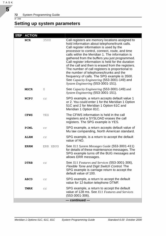
72 System Programming Guideof 206
Setting up system parameters
5T A S K 76
NCR 3500 Call registers are memory locations assigned to hold information about telephone/trunk calls. Call register information is used by the processor to control, connect, route, and time calls within the Meridian 1. The information is gathered from the buffers you just programmed. Call register information is held for the duration of the call and then is erased from the registers. The number of call registers is proportional to the number of telephones/trunks and the frequency of calls. The SPG example is 3500. See Capacity Engineering (553-3001-149) and System Engineering (553-3001-151).
MGCR 0 See Capacity Engineering (553-3001-149) and System Engineering (553-3001-151).
NCPU cr SPG example, a return accepts default value 1 or 2. You could enter 1 for the Meridian 1 Option 51C and 2 for Meridian 1 Option 61C and Meridian 1 Option 81C.
CFWS YES The CFWS information is held in the call registers and a SYSLOAD erases the call registers. The SPG example is YES.
PCML cr SPG example, a return accepts default value of Mu law companding, North American standard.
ALRM cr SPG example, is a return to accept the default value of NO.
ERRM ERR XBUG See X11 System Messages Guide (553-3001-411) for details of these maintenance messages. The SPG example turns off the BUG messages and allows ERR messages.
DTRB cr See X11 Features and Services (553-3001-306), Flexible Tone and Digit Switch Control. The SPG example is carriage return to accept the default value of 100.
ABCD cr SPG example, a return to accept the default value for 12-button telephone DTMF.
TMRK cr SPG example, a return to accept the default value of 128 ms. See X11 Features and Services (553-3001-306).— continued —
STEP ACTION
Meridian 1 Options 51C, 61C, 81C System Programming Guide Standard 6.00 October 2000
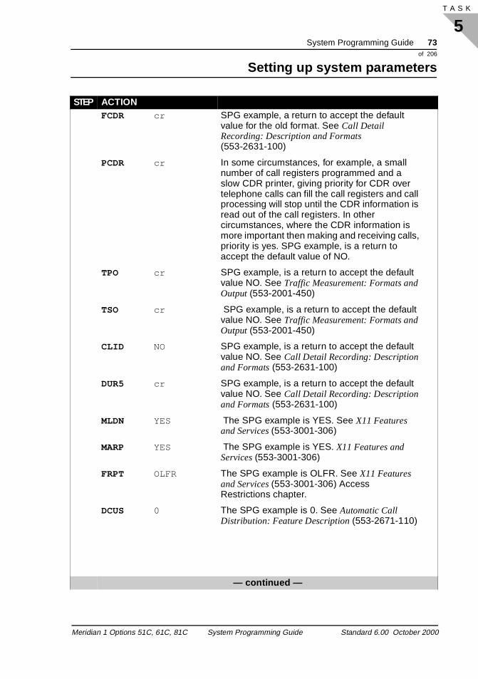
System Programming Guide 73of 206
Setting up system parameters
5T A S K
FCDR cr SPG example, a return to accept the default value for the old format. See Call Detail Recording: Description and Formats (553-2631-100)
PCDR cr In some circumstances, for example, a small number of call registers programmed and a slow CDR printer, giving priority for CDR over telephone calls can fill the call registers and call processing will stop until the CDR information is read out of the call registers. In other circumstances, where the CDR information is more important then making and receiving calls, priority is yes. SPG example, is a return to accept the default value of NO.
TPO cr SPG example, is a return to accept the default value NO. See Traffic Measurement: Formats and Output (553-2001-450)
TSO cr SPG example, is a return to accept the default value NO. See Traffic Measurement: Formats and Output (553-2001-450)
CLID NO SPG example, is a return to accept the default value NO. See Call Detail Recording: Description and Formats (553-2631-100)
DUR5 cr SPG example, is a return to accept the default value NO. See Call Detail Recording: Description and Formats (553-2631-100)
MLDN YES The SPG example is YES. See X11 Features and Services (553-3001-306)
MARP YES The SPG example is YES. X11 Features and Services (553-3001-306)
FRPT OLFR The SPG example is OLFR. See X11 Features and Services (553-3001-306) Access Restrictions chapter.
DCUS 0 The SPG example is 0. See Automatic Call Distribution: Feature Description (553-2671-110)
— continued —
STEP ACTION
Meridian 1 Options 51C, 61C, 81C System Programming Guide Standard 6.00 October 2000
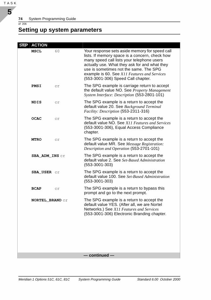
74 System Programming Guideof 206
Setting up system parameters
5T A S K 76
MSCL 60 Your response sets aside memory for speed call lists. If memory space is a concern, check how many speed call lists your telephone users actually use. What they ask for and what they use is sometimes not the same. The SPG example is 60. See X11 Features and Services (553-3001-306) Speed Call chapter.
PMSI cr The SPG example is carriage return to accept the default value NO. See Property Management System Interface: Description (553-2801-101)
NDIS cr The SPG example is a return to accept the default value 20. See Background Terminal Facility: Description (553-2311-316)
OCAC cr The SPG example is a return to accept the default value NO. See X11 Features and Services (553-3001-306), Equal Access Compliance chapter.
MTRO cr The SPG example is a return to accept the default value MR. See Message Registration: Description and Operation (553-2701-101)
SBA_ADM_INS cr The SPG example is a return to accept the default value 2. See Set-Based Administration (553-3001-303)
SBA_USER cr The SPG example is a return to accept the default value 100. See Set-Based Administration (553-3001-303)
BCAP cr The SPG example is a return to bypass this prompt and go to the next prompt.
NORTEL_BRAND cr The SPG example is a return to accept the default value YES. (After all, we are Nortel Networks.) See X11 Features and Services (553-3001-306) Electronic Branding chapter.
— continued —
STEP ACTION
Meridian 1 Options 51C, 61C, 81C System Programming Guide Standard 6.00 October 2000
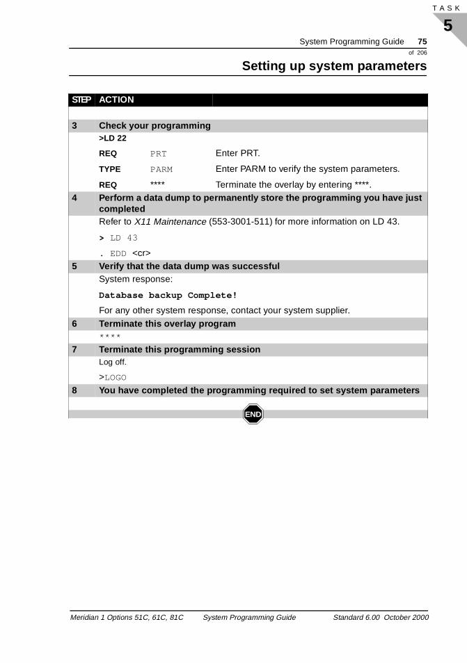
System Programming Guide 75of 206
Setting up system parameters
5T A S K
3 Check your programming>LD 22
REQ PRT Enter PRT.
TYPE PARM Enter PARM to verify the system parameters.
REQ **** Terminate the overlay by entering ****.4 Perform a data dump to permanently store the programming you have just
completedRefer to X11 Maintenance (553-3001-511) for more information on LD 43.
> LD 43
. EDD <cr>5 Verify that the data dump was successful
System response:
Database backup Complete!
For any other system response, contact your system supplier.
6 Terminate this overlay program****
7 Terminate this programming sessionLog off.
>LOGO
8 You have completed the programming required to set system parameters
END
STEP ACTION
Meridian 1 Options 51C, 61C, 81C System Programming Guide Standard 6.00 October 2000

76 System Programming Guideof 206
Setting up system parameters
5T A S K 76
Meridian 1 Options 51C, 61C, 81C System Programming Guide Standard 6.00 October 2000
System Programming Guide 77of 206
Configuring overlay options
6T A S K
for
l es.
om
Configuring overlay options Overlays
Task 6
Basic configuration
A number of overlay program options are available, depending onyour needs. Choose the options that best suit your maintenance requirements.
The information you enter is described in detail below. Proceduresentering this information are provided later in this section.
The Meridian 1 system clock provides the time and date used fordisplay on telephones, for the timestamping of logs and call detairecording, and for the scheduling of automatic maintenance routinSet the time and date in LD 2 before configuring other overlay options.
Each Meridian 1 system has a unique system ID number (SID) fr0000 to 9999. The system ID is used in reports and networking.
The 4-digit ID number can be printed or set by the following commands in LD 2:
� To print the current SID: Enter TSID
� To change the SID: Enter SSID
For more information, see the step-action procedure later in this guide.
Purpose
Date and time
System ID
Meridian 1 Options 51C, 61C, 81C System Programming Guide Standard 6.00 October 2000
78 System Programming Guideof 206
Configuring overlay options
6T A S K 82
ms ing
,
f
he
elps .
The Meridian 1 can run overlay programs continuously in the background during normal operations. Background overlay progracan perform ongoing diagnostics and maintenance without affectsystem operation. You can specify as many background overlay programs as you need. The Meridian 1 loads these overlays sequentially.
To specify the overlay programs that are to run in the backgroundrespond to the BKGD prompt.
Consider setting up traffic studies while configuring maintenance schedules and routines. Traffic studies monitor the performance oyour system under typical working conditions, and provide the information needed to maintain a high level of service for users.
For more information about configuring traffic studies and using tinformation they provide, refer to the Basic Telecom Management Guide.
The Meridian 1 can perform a number of automated maintenance routines at specified intervals or times. Automated maintenance hto identify and correct faults before users become aware of them
Message waiting lamp testsThe Meridian 1 can be set to test all message waiting lamps at a specified time (ideally when testing will not affect users). To set the time for lamp tests, respond to the PBXH prompt.
Background overlay programs
Traffic studies
Automatic maintenance
Meridian 1 Options 51C, 61C, 81C System Programming Guide Standard 6.00 October 2000
System Programming Guide 79of 206
Configuring overlay options
6T A S K
e
his nd
lt lt
Daily routinesThe Meridian 1 can run sets of diagnostic overlay programs at a specified time. To set the time for the running of daily routines, respond to the TODR prompt. To select the overlay programs to brun during the daily routine, respond to the DROL prompt.
Remote peripheral equipment loopback testsThe Meridian 1 can, as part of the daily routines, perform automated 2.0 Mbit/s remote peripheral equipment (RPE) loopback testing. Ttesting includes local loopback. To specify a loop for testing, respoto the TRLL prompt.
Fault detection When the Meridian 1 detects a fault during daily routines, it will automatically run a diagnostic program, LD 45, to identify the faucondition. To specify the number of times LD 45 will run after a fauis detected, respond to the CY45 prompt.
Meridian 1 Options 51C, 61C, 81C System Programming Guide Standard 6.00 October 2000
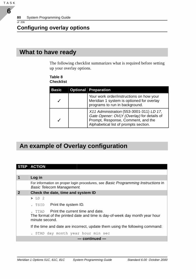
80 System Programming Guideof 206
Configuring overlay options
6T A S K 82
g
The following checklist summarizes what is required before settinup your overlay options.What to have ready
Table 8 Checklist
Basic Optional Preparation
✓Your work order/instructions on how your Meridian 1 system is optioned for overlay programs to run in background.
✓
X11 Administration (553-3001-311) LD 17, Gate Opener: OVLY (Overlay) for details of Prompt, Response, Comment, and the Alphabetical list of prompts section.
An example of Overlay configuration
STEP ACTION
1 Log inFor information on proper login procedures, see Basic Programming Instructions in Basic Telecom Management.
2 Check the date, time and system ID> LD 2
. TSID Print the system ID.
. TTAD Print the current time and date.The format of the printed date and time is day-of-week day month year hour minute second.
If the time and date are incorrect, update them using the following command:
. STAD day month year hour min sec
— continued —
Meridian 1 Options 51C, 61C, 81C System Programming Guide Standard 6.00 October 2000
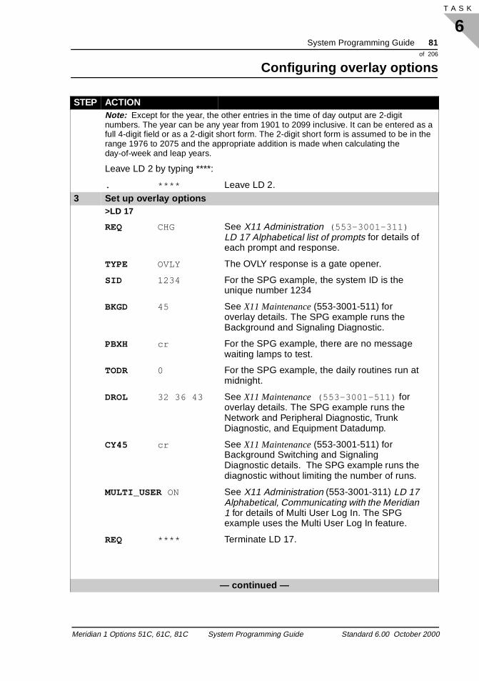
System Programming Guide 81of 206
Configuring overlay options
6T A S K
Note: Except for the year, the other entries in the time of day output are 2-digit numbers. The year can be any year from 1901 to 2099 inclusive. It can be entered as a full 4-digit field or as a 2-digit short form. The 2-digit short form is assumed to be in the range 1976 to 2075 and the appropriate addition is made when calculating the day-of-week and leap years.
Leave LD 2 by typing ****:
. **** Leave LD 2.3 Set up overlay options
>LD 17
REQ CHG See X11 Administration (553-3001-311) LD 17 Alphabetical list of prompts for details of each prompt and response.
TYPE OVLY The OVLY response is a gate opener.
SID 1234 For the SPG example, the system ID is the unique number 1234
BKGD 45 See X11 Maintenance (553-3001-511) for overlay details. The SPG example runs the Background and Signaling Diagnostic.
PBXH cr For the SPG example, there are no message waiting lamps to test.
TODR 0 For the SPG example, the daily routines run at midnight.
DROL 32 36 43 See X11 Maintenance (553-3001-511) for overlay details. The SPG example runs the Network and Peripheral Diagnostic, Trunk Diagnostic, and Equipment Datadump.
CY45 cr See X11 Maintenance (553-3001-511) for Background Switching and Signaling Diagnostic details. The SPG example runs the diagnostic without limiting the number of runs.
MULTI_USER ON See X11 Administration (553-3001-311) LD 17 Alphabetical, Communicating with the Meridian 1 for details of Multi User Log In. The SPG example uses the Multi User Log In feature.
REQ **** Terminate LD 17.
— continued —
STEP ACTION
Meridian 1 Options 51C, 61C, 81C System Programming Guide Standard 6.00 October 2000
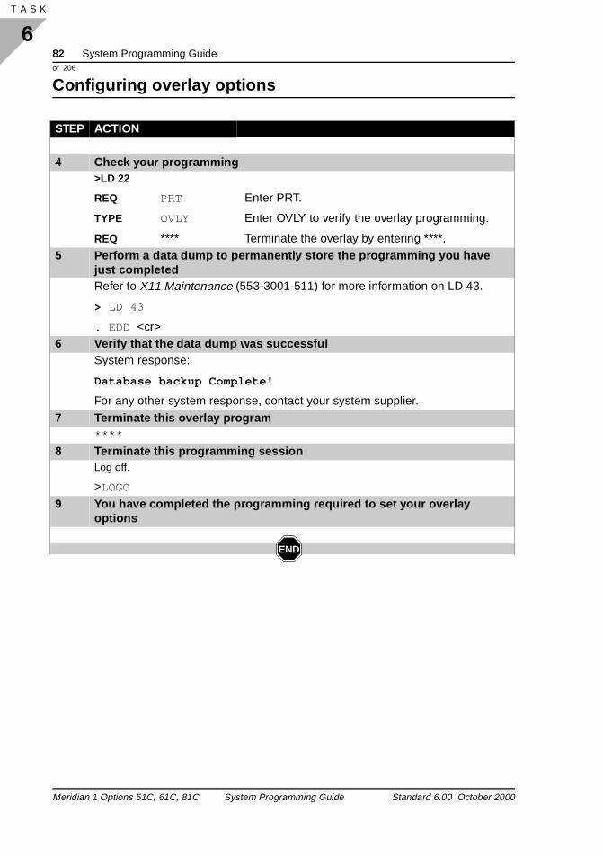
82 System Programming Guideof 206
Configuring overlay options
6T A S K 82
4 Check your programming>LD 22
REQ PRT Enter PRT.
TYPE OVLY Enter OVLY to verify the overlay programming.
REQ **** Terminate the overlay by entering ****.5 Perform a data dump to permanently store the programming you have
just completedRefer to X11 Maintenance (553-3001-511) for more information on LD 43.
> LD 43
. EDD <cr>6 Verify that the data dump was successful
System response:
Database backup Complete!
For any other system response, contact your system supplier.
7 Terminate this overlay program****
8 Terminate this programming sessionLog off.
>LOGO
9 You have completed the programming required to set your overlay options
END
STEP ACTION
Meridian 1 Options 51C, 61C, 81C System Programming Guide Standard 6.00 October 2000
System Programming Guide 83of 206
Setting up passwords
7T A S K
ing ers,
n 1
by
, R1
in
ly le, d a tput
Setting up passwords Passwords
Task 7
Basic configuration
The Meridian 1 is protected from accidental and malicious tamperby passwords that control access to various overlays and customand to the system as a whole.
Configure passwords for all users using LD 17.
Password control is sophisticated, allowing precise control of the areas of the system available to each password user. The Meridiaprovides a number of different types of passwords letting you limit access to varying degrees.
You can force users to log in using a name as well as a pasword turning on the login name option. to do this, enter YES at the LNAME_OPTION prompt in LD 17. When the option is turned onADMIN1 is applied to the current PWD1, ADMIN2 is applied to thecurrent PWD2, USER0 is applied to the current Password 00, USEis applied to the current Password 01, through to USER 99.
With Multi-User Login enabled, more than one user can be loggedwith the same combination of name and password. (No two loginnames can have the same password associated with them.)
When a HOST user logs in, the options set up for the port are onoutput to that port. For example, if two ports are set up (for exampthrough the USER prompt) to output BUG and SCH messages, anHOST user logs in to one of these ports, the other port does not ou
Purpose
User names
Multi-user login
Meridian 1 Options 51C, 61C, 81C System Programming Guide Standard 6.00 October 2000
84 System Programming Guideof 206
Setting up passwords
7T A S K 90
ure rate
N r pt.
BUG and SCH messages until the HOST user logs out. This featremoves the restriction that ports with the same options must opeat the speed of the slowest port.
Basic user passwords provide access to all the overlay programsavailable on the Meridian 1. They are intended for use by administrators who need access to the entire Meridian 1 system.
To change passwords, log into the Meridian 1 using an existing administration password.
The administration password is used to change passwords PW1,PWD2, and SPWD.
To change the first-level administration password, respond to theNPW1 prompt in LD 17. To change a second-level administrationpassword, respond to the NPW2 prompt.
Logging in using the second-level administration password
If your system has the login name option enabled (LNAME_OPTIOset to YES), log in by entering ADMIN2 at the LOGIN prompt. Entethe current second level administration password at the PASS prom
If your Meridian 1 has the Limited Access to Overlays (LAPW) package installed, you can allow specific users access to specificoverlay programs. This helps maintain system security and can prevent accidental and damaging changes to system data.
Basic passwords
Administration passwords
Limited Access to Overlays passwords
Meridian 1 Options 51C, 61C, 81C System Programming Guide Standard 6.00 October 2000
System Programming Guide 85of 206
Setting up passwords
7T A S K
ect u
W
lso and
ST
mpt
d
ed
d
You can also use this feature to allow customer administrators diraccess to their data on the Meridian 1. The LAPW feature lets yolimit an administrator’s access to a specific customer’s or tenant’s data.
Enter the Limited Access to Overlays password number at the LAPprompt in LD 17, the password itself at the PWnn prompt, and the overlays available to that password at the OVLA prompt. You can aspecify customers available to the password at the CUST prompt,tenants available at the TEN prompt.
To enable host mode access for the password, respond to the HOprompt.
Changing Limited Access to Overlays passwords To change a password, enter the old password at the NPWD proin LD 17, and the new password at the NLPW prompt.
Attempts at password breaking, or hacking, result in lock-outs of affected ports. Lock outs are logged on maintenance terminals ansupervisory stations, providing an indication of potential security problems.
To set the Failed Login Threshold (the number of failed logins needto trigger a lockout of the port), respond to the FLTH prompt in LD 17. To set a lock-out time (the time, in minutes, a port is lockeout after the Failed Login threshold is exceeded), respond to the LOCK prompt.
Security thresholds
Meridian 1 Options 51C, 61C, 81C System Programming Guide Standard 6.00 October 2000
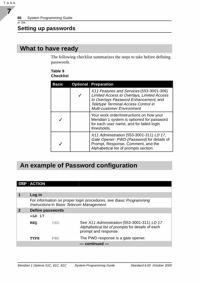
86 System Programming Guideof 206
Setting up passwords
7T A S K 90
ing
The following checklist summarizes the steps to take before definpasswords.What to have ready
Table 9 Checklist
Basic Optional Preparation
✓X11 Features and Services (553-3001-306) Limited Access to Overlays, Limited Access to Overlays Password Enhancement, and Teletype Terminal Access Control in Multi-customer Environment
✓Your work order/instructions on how your Meridian 1 system is optioned for password for each user name, and for failed login thresholds.
✓
X11 Administration (553-3001-311) LD 17, Gate Opener: PWD (Password) for details of Prompt, Response, Comment, and the Alphabetical list of prompts section.
An example of Password configuration
STEP ACTION
1 Log inFor information on proper login procedures, see Basic Programming Instructions in Basic Telecom Management.
2 Define passwords>LD 17
REQ CHG See X11 Administration (553-3001-311) LD 17 Alphabetical list of prompts for details of each prompt and response.
TYPE PWD The PWD response is a gate opener.
— continued —
Meridian 1 Options 51C, 61C, 81C System Programming Guide Standard 6.00 October 2000
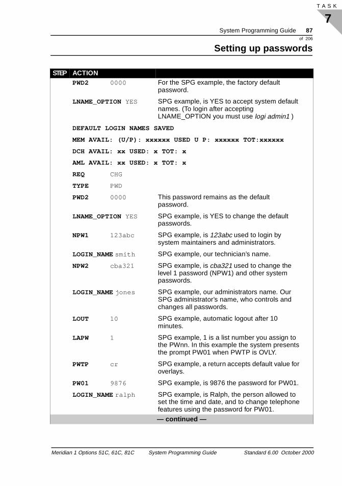
System Programming Guide 87of 206
Setting up passwords
7T A S K
PWD2 0000 For the SPG example, the factory default password.
LNAME_OPTION YES SPG example, is YES to accept system default names. (To login after accepting LNAME_OPTION you must use logi admin1 )
DEFAULT LOGIN NAMES SAVED
MEM AVAIL: (U/P): xxxxxx USED U P: xxxxxx TOT:xxxxxx
DCH AVAIL: xx USED: x TOT: x
AML AVAIL: xx USED: x TOT: x
REQ CHG
TYPE PWD
PWD2 0000 This password remains as the default password.
LNAME_OPTION YES SPG example, is YES to change the default passwords.
NPW1 123abc SPG example, is 123abc used to login by system maintainers and administrators.
LOGIN_NAME smith SPG example, our technician’s name.
NPW2 cba321 SPG example, is cba321 used to change the level 1 password (NPW1) and other system passwords.
LOGIN_NAME jones SPG example, our administrators name. Our SPG administrator’s name, who controls and changes all passwords.
LOUT 10 SPG example, automatic logout after 10 minutes.
LAPW 1 SPG example, 1 is a list number you assign to the PWnn. In this example the system presents the prompt PW01 when PWTP is OVLY.
PWTP cr SPG example, a return accepts default value for overlays.
PW01 9876 SPG example, is 9876 the password for PW01.
LOGIN_NAME ralph SPG example, is Ralph, the person allowed to set the time and date, and to change telephone features using the password for PW01.
— continued —
STEP ACTION
Meridian 1 Options 51C, 61C, 81C System Programming Guide Standard 6.00 October 2000
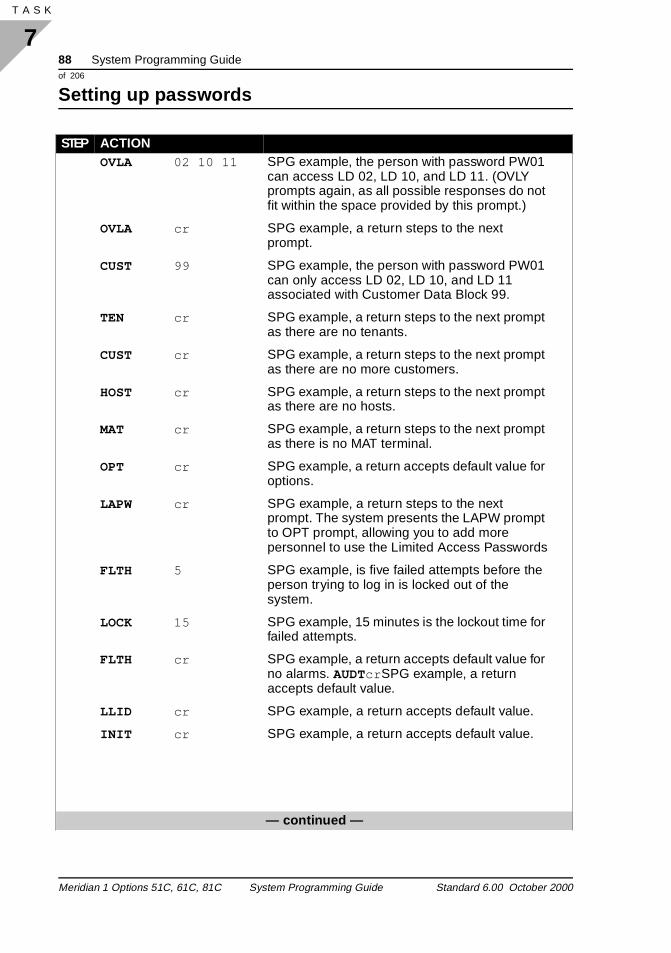
88 System Programming Guideof 206
Setting up passwords
7T A S K 90
OVLA 02 10 11 SPG example, the person with password PW01 can access LD 02, LD 10, and LD 11. (OVLY prompts again, as all possible responses do not fit within the space provided by this prompt.)
OVLA cr SPG example, a return steps to the next prompt.
CUST 99 SPG example, the person with password PW01 can only access LD 02, LD 10, and LD 11 associated with Customer Data Block 99.
TEN cr SPG example, a return steps to the next prompt as there are no tenants.
CUST cr SPG example, a return steps to the next prompt as there are no more customers.
HOST cr SPG example, a return steps to the next prompt as there are no hosts.
MAT cr SPG example, a return steps to the next prompt as there is no MAT terminal.
OPT cr SPG example, a return accepts default value for options.
LAPW cr SPG example, a return steps to the next prompt. The system presents the LAPW prompt to OPT prompt, allowing you to add more personnel to use the Limited Access Passwords
FLTH 5 SPG example, is five failed attempts before the person trying to log in is locked out of the system.
LOCK 15 SPG example, 15 minutes is the lockout time for failed attempts.
FLTH cr SPG example, a return accepts default value for no alarms. AUDTcr SPG example, a return accepts default value.
LLID cr SPG example, a return accepts default value.
INIT cr SPG example, a return accepts default value.
— continued —
STEP ACTION
Meridian 1 Options 51C, 61C, 81C System Programming Guide Standard 6.00 October 2000
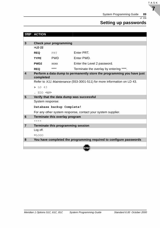
System Programming Guide 89of 206
Setting up passwords
7T A S K
3 Check your programming>LD 22
REQ PRT Enter PRT.
TYPE PWD Enter PWD.
PWD2 xxxx Enter the Level 2 password.
REQ **** Terminate the overlay by entering ****.4 Perform a data dump to permanently store the programming you have just
completedRefer to X11 Maintenance (553-3001-511) for more information on LD 43.
> LD 43
. EDD <cr>5 Verify that the data dump was successful
System response:
Database backup Complete!
For any other system response, contact your system supplier.
6 Terminate this overlay program****
7 Terminate this programming sessionLog off.
>LOGO
8 You have completed the programming required to configure passwords
END
STEP ACTION
Meridian 1 Options 51C, 61C, 81C System Programming Guide Standard 6.00 October 2000

90 System Programming Guideof 206
Setting up passwords
7T A S K 90
Meridian 1 Options 51C, 61C, 81C System Programming Guide Standard 6.00 October 2000
System Programming Guide 91of 206
Entering customer data
8T A S K
ntal
).
ups or s
s
Entering customer data Customer data
Task 8
Customer data
Each customer connected to the Meridian 1 has a Customer DataBlock (CDB). The CDB is a set of parameters that control specificfeatures and options for the customer. Enter information for eachcustomer who will be sharing the Meridian 1.
You can group customer telephones together using the DepartmeListed Directory Number (DLDN) feature. Telephones ring as a group.
Each customer can have up to four DLDN groups. Each group is identified by one of the customer’s listed directory numbers (LDN
You can separate a customer’s telephones into Dial Intercom Gro(DIG). Telephones within a group can call each other using one- two-digit codes, providing intercom-like service. (Two-digit dialing irequired for a DIG of more than ten stations.)
A total of 100 telephone extensions can belong to each DIG.
Telecommunications needs change during non-business hours. Incoming calls can be routed to a security desk instead of to the attendant. Night service automatically changes the routing of callduring non-business hours, permitting incoming calls normally directed to the attendant to be routed to another destination.
Purpose
Departmental listed directory numbers
Dial intercom groups
Night service
Meridian 1 Options 51C, 61C, 81C System Programming Guide Standard 6.00 October 2000
92 System Programming Guideof 206
Entering customer data
8T A S K 120
d t
r d
e.
ers
is The ber
the
ks.
has e
he
t as
e
the
Normal Night ServiceWith the feature active, the existing Night Service feature is enhanceby providing a night (NITE) prompt for applicable DID trunks. Nighnumbers for DID trunks can be defined in their respective trunk blocks against the prompt. Attendants will be able to change theinight numbers by specifying their corresponding access codes anmember numbers using the existing Flexible Night Service featur
Group Night ServiceThe customer is allowed to assign individual Public Switched Telephone Network (PSTN) trunks to one of ten night group numb(0 to 9). Each Night group has up to ten night directory numbers associated with it. During Night Service, incoming calls on a trunkrouted to one of the directory numbers associated with that trunk. actual number called is determined by a Night Service Option numcorresponding to the Night Group number programmed by the attendant during day service.
When an incoming call is routed to a busy directory number, an optional Night Call Waiting tone can be applied to that number tonotify the user that a call is waiting. The call on the trunk will be queued until the night directory number becomes free.
The same feature requirements apply to Night Service, as well asfollowing requirements:
� Enhanced Night Service does not apply to Auto-terminate trun
� Enhanced Night Service is permanently activated if the system no attendant and the ENS option is set to YES. In this case, thNight Service Option Number can only be programmed from tCustomer Data block (LD 15).
� Enhanced Night Service makes use of only one Speed Call listhe Night Number Table.
� The operation of the optional Night Call Waiting Tone is the samas those of the Call Waiting Tone.
Night Service Option 0 and Night Service Group 0 are reserved forcustomer Night number, and must not be programmed in LD 18.
Meridian 1 Options 51C, 61C, 81C System Programming Guide Standard 6.00 October 2000
System Programming Guide 93of 206
Entering customer data
8T A S K
ng
of ll
ght th ce ing
nk SA
nt able re
ade
et
Feature interactionsCall Waiting This feature terminates incoming Night calls to busy DNs by applyiCall Waiting. This will be done even if the Night DN is an analog (500/2500 type) telephone with Call Waiting Denied (CWD) Class Service, or if the Night DN is a Meridian 1 telephone without a CaWaiting (CWT) key assigned.
All telephones (analog 500/2500 type and Meridian 1) are given NiCall Waiting tone, if the NWT prompt in LD 15 was responded to wi"YES", regardless of the Warning Tone (WTA,WTD) Class of Servisetting of the set. Meridian 1 telephones are given Night Call Waittone in the handset instead of the speaker buzz for Call Waiting.
Direct Inward System Access (DISA) It is not possible to assign a Night Service Group Number to any truthat is a member of a route which is set to auto-terminate on a DIDN.
Multi-Tenant Service Any restrictions that exist in the system preventing individual tenaaccess to certain routes are not checked when the Night Number Tis programmed. The technician can ensure all such restrictions ataken into consideration.
The tenant to route restrictions are enforced when an attempt is mto terminate an incoming call on a Night DN through the Night Number Table. If the termination to the Night DN is not allowed, overflow tone (fast busy) is given to the incoming trunk.
Trunk Barring (Sets) Any incoming call that is routed by Enhanced Night Service to a sfrom which it is barred will not be connected. Overflow tone (fast busy) is given to the incoming trunk instead.
Meridian 1 Options 51C, 61C, 81C System Programming Guide Standard 6.00 October 2000
94 System Programming Guideof 206
Entering customer data
8T A S K 120
ill
n d f
that f ge of
ions
Trunk to Trunk Barring Any incoming trunk call that is routed to an outgoing PSTN trunk wbe barred if Enhanced Night Service is active. Overflow tone is given to the incoming trunk instead. This restriction is in addition to theconfigured trunk barring for the system.
Warning Tone All telephones (analog 500/2500 type and Meridian 1) will be giveNight Call Waiting tone, if the NWT prompt in LD 15 was respondeto with "YES", regardless of the Warning Tone (WTA/WTD) Class oService setting of the set.
Special prefix (SPRE) codes let telephone users access featuresare not available as feature keys on their telephone sets. Users oanalog 500/2500 telephones can use SPRE codes to take advantaadvanced call features.
The Attendant Directory Number lets internal telephone and TIE trunk users call the attendant by dialing a code (typically 0).
You can specify a number of options for each customer. These optare described below.
Camp-on toneCamp-on tone is a tone provided to a caller waiting for a called telephone to become idle.
Enhanced busy lamp field The customer can have an enhanced busy lamp field on M2250 attendant consoles.
Special prefix codes
Attendant directory number
Customer options
Meridian 1 Options 51C, 61C, 81C System Programming Guide Standard 6.00 October 2000
System Programming Guide 95of 206
Entering customer data
8T A S K
n
ting
Incoming call indicators The customer can have either 10 or 20 incoming call indicators oM2250 attendant consoles. The default is 10.
Trunk group busy lamp field This option indicates to users whether trunk groups to specific destinations are busy.
Originating side ringing cadence The customer can have ringing cadence determined by the originaparty.
Meridian 1 Options 51C, 61C, 81C System Programming Guide Standard 6.00 October 2000
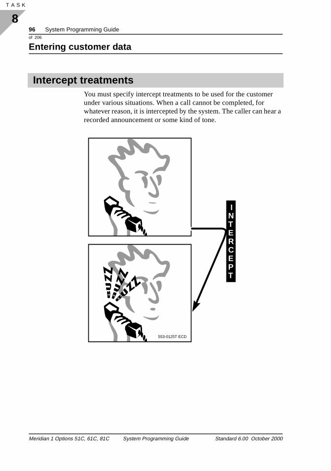
96 System Programming Guideof 206
Entering customer data
8T A S K 120
ar a
You must specify intercept treatments to be used for the customer under various situations. When a call cannot be completed, for whatever reason, it is intercepted by the system. The caller can herecorded announcement or some kind of tone.
Intercept treatments
NTERCEPT
I
553-0125T ECD
Meridian 1 Options 51C, 61C, 81C System Programming Guide Standard 6.00 October 2000
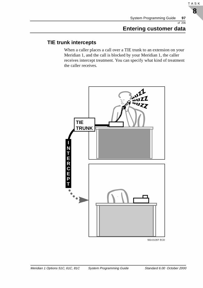
System Programming Guide 97of 206
Entering customer data
8T A S K
ur
ent
TIE trunk intercepts When a caller places a call over a TIE trunk to an extension on yoMeridian 1, and the call is blocked by your Meridian 1, the caller receives intercept treatment. You can specify what kind of treatmthe caller receives.
TIETRUNK
NTERCEPT
I
553-0126T ECD
Meridian 1 Options 51C, 61C, 81C System Programming Guide Standard 6.00 October 2000
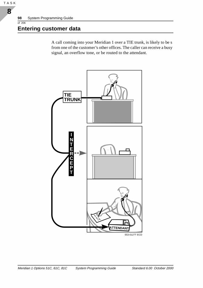
98 System Programming Guideof 206
Entering customer data
8T A S K 120
s usy
A call coming into your Meridian 1 over a TIE trunk, is likely to be from one of the customer’s other offices. The caller can receive a bsignal, an overflow tone, or be routed to the attendant.
ATTENDANT
NTERCEPT
I
TIETRUNK
553-0127T ECD
Meridian 1 Options 51C, 61C, 81C System Programming Guide Standard 6.00 October 2000
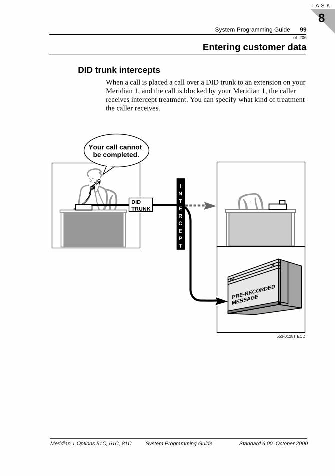
System Programming Guide 99of 206
Entering customer data
8T A S K
ur
ent
DID trunk intercepts When a call is placed a call over a DID trunk to an extension on yoMeridian 1, and the call is blocked by your Meridian 1, the caller receives intercept treatment. You can specify what kind of treatmthe caller receives.
PRE-RECORDED
MESSAGE
Your call cannot be completed.
DIDTRUNK
INTERCEPT
553-0128T ECD
Meridian 1 Options 51C, 61C, 81C System Programming Guide Standard 6.00 October 2000
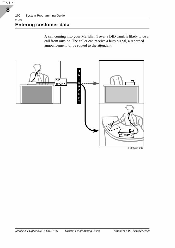
100 System Programming Guideof 206
Entering customer data
8T A S K 120
a
A call coming into your Meridian 1 over a DID trunk is likely to be call from outside. The caller can receive a busy signal, a recordedannouncement, or be routed to the attendant.
ATTENDANT
DIDTRUNK
NTERCEPT
I
553-0129T ECD
Meridian 1 Options 51C, 61C, 81C System Programming Guide Standard 6.00 October 2000
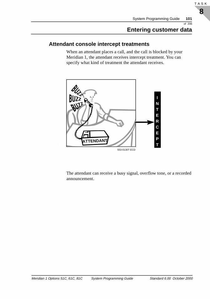
System Programming Guide 101of 206
Entering customer data
8T A S K
ded
Attendant console intercept treatments When an attendant places a call, and the call is blocked by your Meridian 1, the attendant receives intercept treatment. You can specify what kind of treatment the attendant receives.
The attendant can receive a busy signal, overflow tone, or a recorannouncement.
ATTENDANT
INTERCEPT
553-0130T ECD
Meridian 1 Options 51C, 61C, 81C System Programming Guide Standard 6.00 October 2000
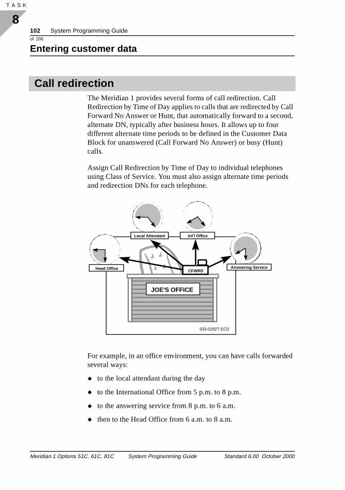
102 System Programming Guideof 206
Entering customer data
8T A S K 120
all d,
a
ds
ed
The Meridian 1 provides several forms of call redirection. Call Redirection by Time of Day applies to calls that are redirected by CForward No Answer or Hunt, that automatically forward to a seconalternate DN, typically after business hours. It allows up to four different alternate time periods to be defined in the Customer DatBlock for unanswered (Call Forward No Answer) or busy (Hunt) calls.
Assign Call Redirection by Time of Day to individual telephones using Class of Service. You must also assign alternate time perioand redirection DNs for each telephone.
For example, in an office environment, you can have calls forwardseveral ways:
� to the local attendant during the day
� to the International Office from 5 p.m. to 8 p.m.
� to the answering service from 8 p.m. to 6 a.m.
� then to the Head Office from 6 a.m. to 8 a.m.
Call redirection
533-0292T ECD
JOE'S OFFICE
CFWRDHead Office Answering Service
Int'l OfficeLocal Attendant
Meridian 1 Options 51C, 61C, 81C System Programming Guide Standard 6.00 October 2000
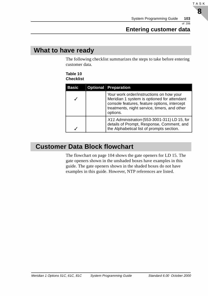
System Programming Guide 103of 206
Entering customer data
8T A S K
ing
e s
The following checklist summarizes the steps to take before entercustomer data.
The flowchart on page 104 shows the gate openers for LD 15. Thgate openers shown in the unshaded boxes have examples in thiguide. The gate openers shown in the shaded boxes do not haveexamples in this guide. However, NTP references are listed.
What to have ready
Table 10 Checklist
Basic Optional Preparation
✓Your work order/instructions on how your Meridian 1 system is optioned for attendant console features, feature options, intercept treatments, night service, timers, and other options.
✓
X11 Administration (553-3001-311) LD 15, for details of Prompt, Response, Comment, and the Alphabetical list of prompts section.
Customer Data Block flowchart
Meridian 1 Options 51C, 61C, 81C System Programming Guide Standard 6.00 October 2000
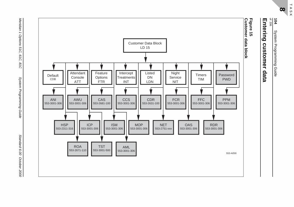
104 S
ystem P
rogramm
ing Guide
of206
Entering custom
er data
Meridian 1 O
p
8 T A
S K
120
Figure 15
Custom
er data block
553-A059
PasswordPWD
TimersTIM
OAS53-3001-306
RDR553-3001-306
PPM553-3001-306
FFC553-3001-30606
tions 51C, 61C
, 81CS
ystem P
rogramm
ing Guide
Standard 6.00 O
ctober2000
Customer Data BlockLD 15
AttendantConsole
ATT
InterceptTreatments
INT
FeatureOptions
FTR
ListedDN
LDN
NightService
NIT
HSP553-2311-316
ISM553-3001-306
ICP553-3001-306
MOP553-3001-306 5
NET553-2751-xxx
FCR553-3001-3
CDR553-2631-100
CCS553-3001-306
CAS553-2681-100
AWU553-3001-306
ANI553-3001-306
DefaultCDB
TST553-3001-500
ROA553-2671-110
AML553-3001-306
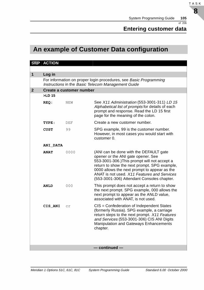
System Programming Guide 105of 206
Entering customer data
8T A S K
An example of Customer Data configuration
STEP ACTION
1 Log inFor information on proper login procedures, see Basic Programming Instructions in the Basic Telecom Management Guide
2 Create a customer number>LD 15
REQ: NEW See X11 Administration (553-3001-311) LD 15 Alphabetical list of prompts for details of each prompt and response. Read the LD 15 first page for the meaning of the colon.
TYPE: DEF Create a new customer number.
CUST 99 SPG example, 99 is the customer number. However, in most cases you would start with customer 0.
ANI_DATA
ANAT 0000 (ANI can be done with the DEFAULT gate opener or the ANI gate opener. See 553-3001-306.)This prompt will not accept a return to show the next prompt. SPG example, 0000 allows the next prompt to appear as the ANAT is not used. X11 Features and Services (553-3001-306) Attendant Consoles chapter.
ANLD 000 This prompt does not accept a return to show the next prompt. SPG example, 000 allows the next prompt to appear as the ANLD value, associated with ANAT, is not used.
CIS_ANI cr CIS = Confederation of Independent States (formerly Russia). SPG example, a carriage return steps to the next prompt. X11 Features and Services (553-3001-306) CIS ANI Digits Manipulation and Gateways Enhancements chapter.
— continued —
Meridian 1 Options 51C, 61C, 81C System Programming Guide Standard 6.00 October 2000
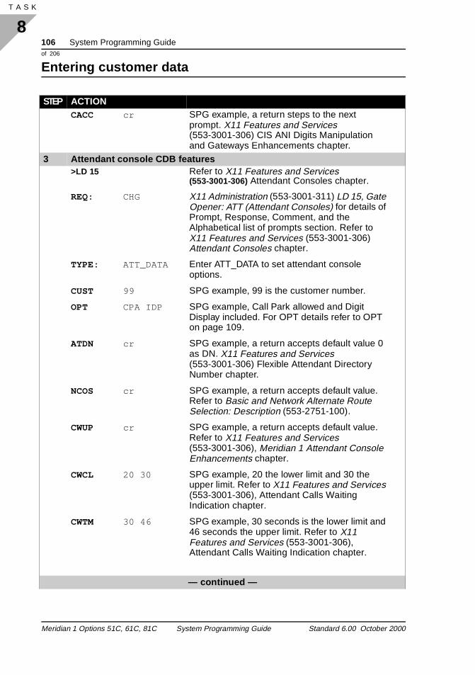
106 System Programming Guideof 206
Entering customer data
8T A S K 120
CACC cr SPG example, a return steps to the next prompt. X11 Features and Services (553-3001-306) CIS ANI Digits Manipulation and Gateways Enhancements chapter.
3 Attendant console CDB features>LD 15 Refer to X11 Features and Services
(553-3001-306) Attendant Consoles chapter.
REQ: CHG X11 Administration (553-3001-311) LD 15, Gate Opener: ATT (Attendant Consoles) for details of Prompt, Response, Comment, and the Alphabetical list of prompts section. Refer to X11 Features and Services (553-3001-306) Attendant Consoles chapter.
TYPE: ATT_DATA Enter ATT_DATA to set attendant console options.
CUST 99 SPG example, 99 is the customer number.
OPT CPA IDP SPG example, Call Park allowed and Digit Display included. For OPT details refer to OPT on page 109.
ATDN cr SPG example, a return accepts default value 0 as DN. X11 Features and Services (553-3001-306) Flexible Attendant Directory Number chapter.
NCOS cr SPG example, a return accepts default value. Refer to Basic and Network Alternate Route Selection: Description (553-2751-100).
CWUP cr SPG example, a return accepts default value. Refer to X11 Features and Services (553-3001-306), Meridian 1 Attendant Console Enhancements chapter.
CWCL 20 30 SPG example, 20 the lower limit and 30 the upper limit. Refer to X11 Features and Services (553-3001-306), Attendant Calls Waiting Indication chapter.
CWTM 30 46 SPG example, 30 seconds is the lower limit and 46 seconds the upper limit. Refer to X11 Features and Services (553-3001-306), Attendant Calls Waiting Indication chapter.
— continued —
STEP ACTION
Meridian 1 Options 51C, 61C, 81C System Programming Guide Standard 6.00 October 2000
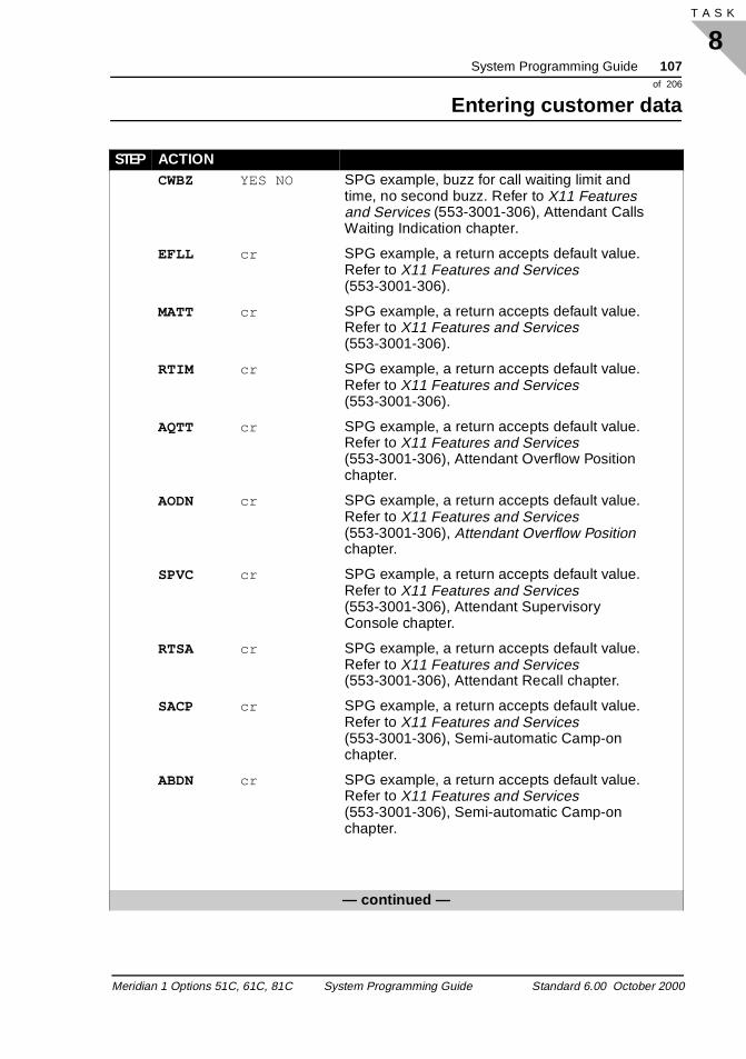
System Programming Guide 107of 206
Entering customer data
8T A S K
CWBZ YES NO SPG example, buzz for call waiting limit and time, no second buzz. Refer to X11 Features and Services (553-3001-306), Attendant Calls Waiting Indication chapter.
EFLL cr SPG example, a return accepts default value. Refer to X11 Features and Services (553-3001-306).
MATT cr SPG example, a return accepts default value. Refer to X11 Features and Services (553-3001-306).
RTIM cr SPG example, a return accepts default value. Refer to X11 Features and Services (553-3001-306).
AQTT cr SPG example, a return accepts default value. Refer to X11 Features and Services (553-3001-306), Attendant Overflow Position chapter.
AODN cr SPG example, a return accepts default value. Refer to X11 Features and Services (553-3001-306), Attendant Overflow Position chapter.
SPVC cr SPG example, a return accepts default value. Refer to X11 Features and Services (553-3001-306), Attendant Supervisory Console chapter.
RTSA cr SPG example, a return accepts default value. Refer to X11 Features and Services (553-3001-306), Attendant Recall chapter.
SACP cr SPG example, a return accepts default value. Refer to X11 Features and Services (553-3001-306), Semi-automatic Camp-on chapter.
ABDN cr SPG example, a return accepts default value. Refer to X11 Features and Services (553-3001-306), Semi-automatic Camp-on chapter.
— continued —
STEP ACTION
Meridian 1 Options 51C, 61C, 81C System Programming Guide Standard 6.00 October 2000
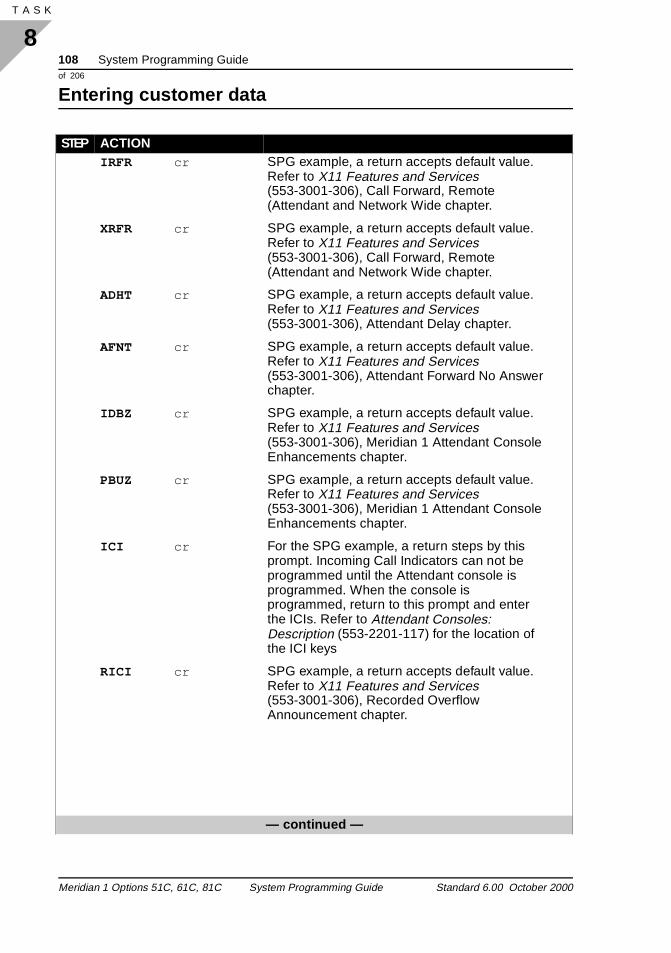
108 System Programming Guideof 206
Entering customer data
8T A S K 120
IRFR cr SPG example, a return accepts default value. Refer to X11 Features and Services (553-3001-306), Call Forward, Remote (Attendant and Network Wide chapter.
XRFR cr SPG example, a return accepts default value. Refer to X11 Features and Services (553-3001-306), Call Forward, Remote (Attendant and Network Wide chapter.
ADHT cr SPG example, a return accepts default value. Refer to X11 Features and Services (553-3001-306), Attendant Delay chapter.
AFNT cr SPG example, a return accepts default value. Refer to X11 Features and Services (553-3001-306), Attendant Forward No Answer chapter.
IDBZ cr SPG example, a return accepts default value. Refer to X11 Features and Services (553-3001-306), Meridian 1 Attendant Console Enhancements chapter.
PBUZ cr SPG example, a return accepts default value. Refer to X11 Features and Services (553-3001-306), Meridian 1 Attendant Console Enhancements chapter.
ICI cr For the SPG example, a return steps by this prompt. Incoming Call Indicators can not be programmed until the Attendant console is programmed. When the console is programmed, return to this prompt and enter the ICIs. Refer to Attendant Consoles: Description (553-2201-117) for the location of the ICI keys
RICI cr SPG example, a return accepts default value. Refer to X11 Features and Services (553-3001-306), Recorded Overflow Announcement chapter.
— continued —
STEP ACTION
Meridian 1 Options 51C, 61C, 81C System Programming Guide Standard 6.00 October 2000
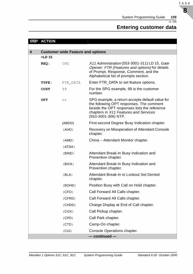
System Programming Guide 109of 206
Entering customer data
8T A S K
4 Customer wide Feature and options>LD 15
REQ: CHG X11 Administration (553-3001-311) LD 15, Gate Opener: FTR (Features and options) for details of Prompt, Response, Comment, and the Alphabetical list of prompts section.
TYPE: FTR_DATA Enter FTR_DATA to set feature options.
CUST 99 For the SPG example, 99 is the customer number.
OPT cr SPG example, a return accepts default value for the following OPT responses. The comment beside the OPT responses lists the reference chapters in X11 Features and Services (553-3001-306) NTP.
(ABDD) First-second Degree Busy Indication chapter.
( AHD) Recovery on Misoperation of Attendant Console chapter.
( AMD) China – Attendant Monitor chapter.
( ATDA)
( BIND) Attendant Break-In Busy Indication and Prevention chapter.
( BIXA) Attendant Break-In Busy Indication and Prevention chapter.
( BLA) Attendant Break-In to Lockout Set Denied chapter.
( BOHD) Position Busy with Call on Hold chapter.
( CFO) Call Forward All Calls chapter.
( CFRD) Call Forward All Calls chapter.
( CHDD) Charge Display at End of Call chapter.
( COX) Call Pickup chapter.
( CPD) Call Park chapter.
( CTD) Camp-On chapter.
( CUI) Console Operations chapter.
— continued —
STEP ACTION
Meridian 1 Options 51C, 61C, 81C System Programming Guide Standard 6.00 October 2000
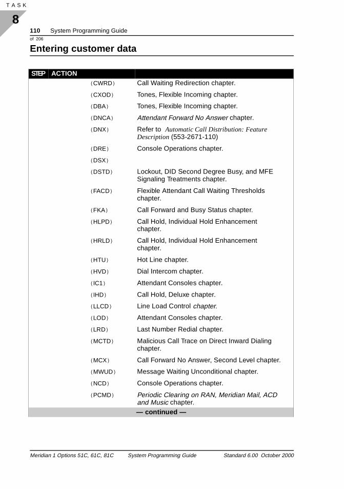
110 System Programming Guideof 206
Entering customer data
8T A S K 120
( CWRD) Call Waiting Redirection chapter.
( CXOD) Tones, Flexible Incoming chapter.
( DBA) Tones, Flexible Incoming chapter.
( DNCA) Attendant Forward No Answer chapter.
( DNX) Refer to Automatic Call Distribution: Feature Description (553-2671-110)
( DRE) Console Operations chapter.
( DSX)
( DSTD) Lockout, DID Second Degree Busy, and MFE Signaling Treatments chapter.
( FACD) Flexible Attendant Call Waiting Thresholds chapter.
( FKA) Call Forward and Busy Status chapter.
( HLPD) Call Hold, Individual Hold Enhancement chapter.
( HRLD) Call Hold, Individual Hold Enhancement chapter.
( HTU) Hot Line chapter.
( HVD) Dial Intercom chapter.
( IC1) Attendant Consoles chapter.
( IHD) Call Hold, Deluxe chapter.
( LLCD) Line Load Control chapter.
( LOD) Attendant Consoles chapter.
( LRD) Last Number Redial chapter.
( MCTD) Malicious Call Trace on Direct Inward Dialing chapter.
( MCX) Call Forward No Answer, Second Level chapter.
( MWUD) Message Waiting Unconditional chapter.
( NCD) Console Operations chapter.
( PCMD) Periodic Clearing on RAN, Meridian Mail, ACD and Music chapter.— continued —
STEP ACTION
Meridian 1 Options 51C, 61C, 81C System Programming Guide Standard 6.00 October 2000
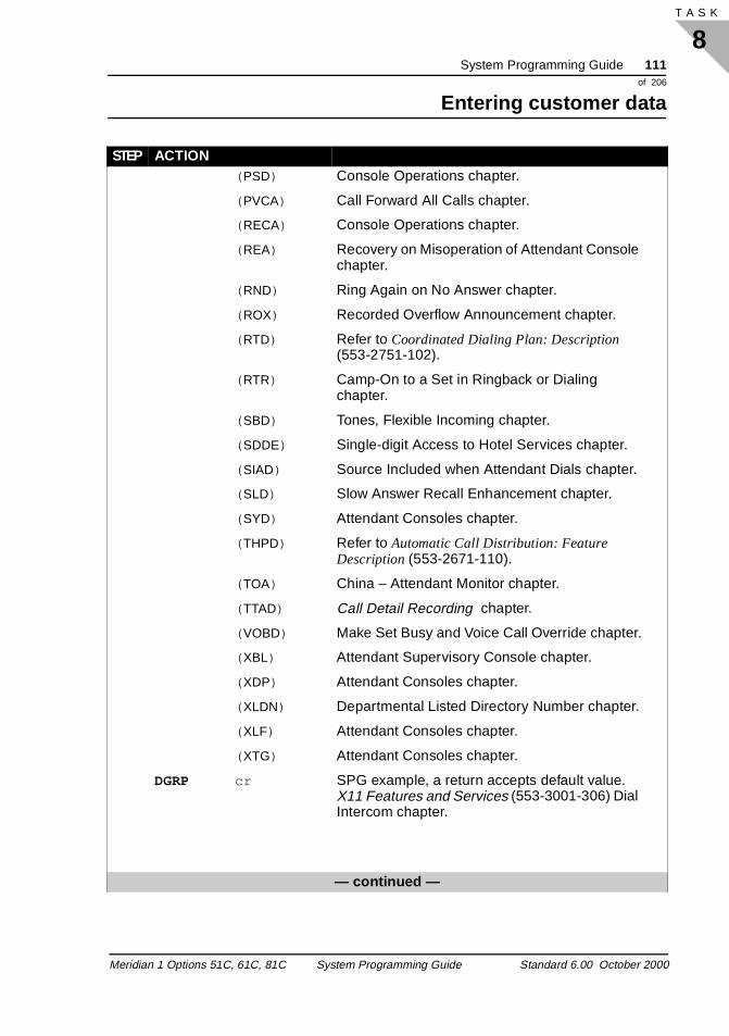
System Programming Guide 111of 206
Entering customer data
8T A S K
( PSD) Console Operations chapter.
( PVCA) Call Forward All Calls chapter.
( RECA) Console Operations chapter.
( REA) Recovery on Misoperation of Attendant Console chapter.
( RND) Ring Again on No Answer chapter.
( ROX) Recorded Overflow Announcement chapter.
( RTD) Refer to Coordinated Dialing Plan: Description (553-2751-102).
( RTR) Camp-On to a Set in Ringback or Dialing chapter.
( SBD) Tones, Flexible Incoming chapter.
( SDDE) Single-digit Access to Hotel Services chapter.
( SIAD) Source Included when Attendant Dials chapter.
( SLD) Slow Answer Recall Enhancement chapter.
( SYD) Attendant Consoles chapter.
( THPD) Refer to Automatic Call Distribution: Feature Description (553-2671-110).
( TOA) China – Attendant Monitor chapter.
( TTAD) Call Detail Recording chapter.
( VOBD) Make Set Busy and Voice Call Override chapter.
( XBL) Attendant Supervisory Console chapter.
( XDP) Attendant Consoles chapter.
( XLDN) Departmental Listed Directory Number chapter.
( XLF) Attendant Consoles chapter.
( XTG) Attendant Consoles chapter.
DGRP cr SPG example, a return accepts default value. X11 Features and Services (553-3001-306) Dial Intercom chapter.
— continued —
STEP ACTION
Meridian 1 Options 51C, 61C, 81C System Programming Guide Standard 6.00 October 2000
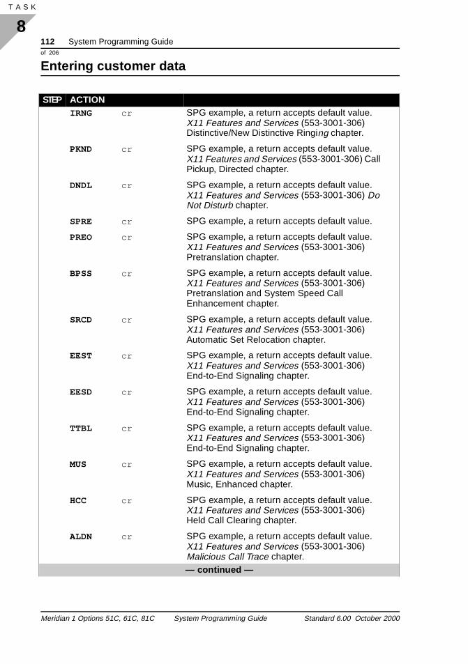
112 System Programming Guideof 206
Entering customer data
8T A S K 120
IRNG cr SPG example, a return accepts default value. X11 Features and Services (553-3001-306) Distinctive/New Distinctive Ringing chapter.
PKND cr SPG example, a return accepts default value. X11 Features and Services (553-3001-306) Call Pickup, Directed chapter.
DNDL cr SPG example, a return accepts default value. X11 Features and Services (553-3001-306) Do Not Disturb chapter.
SPRE cr SPG example, a return accepts default value.
PREO cr SPG example, a return accepts default value. X11 Features and Services (553-3001-306) Pretranslation chapter.
BPSS cr SPG example, a return accepts default value. X11 Features and Services (553-3001-306) Pretranslation and System Speed Call Enhancement chapter.
SRCD cr SPG example, a return accepts default value. X11 Features and Services (553-3001-306) Automatic Set Relocation chapter.
EEST cr SPG example, a return accepts default value. X11 Features and Services (553-3001-306) End-to-End Signaling chapter.
EESD cr SPG example, a return accepts default value. X11 Features and Services (553-3001-306) End-to-End Signaling chapter.
TTBL cr SPG example, a return accepts default value. X11 Features and Services (553-3001-306) End-to-End Signaling chapter.
MUS cr SPG example, a return accepts default value. X11 Features and Services (553-3001-306) Music, Enhanced chapter.
HCC cr SPG example, a return accepts default value. X11 Features and Services (553-3001-306) Held Call Clearing chapter.
ALDN cr SPG example, a return accepts default value. X11 Features and Services (553-3001-306) Malicious Call Trace chapter.— continued —
STEP ACTION
Meridian 1 Options 51C, 61C, 81C System Programming Guide Standard 6.00 October 2000
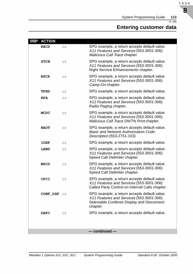
System Programming Guide 113of 206
Entering customer data
8T A S K
RECD cr SPG example, a return accepts default value. X11 Features and Services (553-3001-306) Malicious Call Trace chapter.
STCB cr SPG example, a return accepts default value. X11 Features and Services (553-3001-306) Night Service Enhancements chapter.
NSCP cr SPG example, a return accepts default value. X11 Features and Services (553-3001-306) Camp-On chapter.
TFRD cr SPG example, a return accepts default value.
RPA cr SPG example, a return accepts default value. X11 Features and Services (553-3001-306) Radio Paging chapter.
MCDC cr SPG example, a return accepts default value. X11 Features and Services (553-3001-306) Malicious Call Trace DN/TN Print chapter.
NAUT cr SPG example, a return accepts default value. Basic and Network Authorization Code: Description (553-2751-103)
IDEF cr SPG example, a return accepts default value.
LEND cr SPG example, a return accepts default value. X11 Features and Services (553-3001-306) Speed Call Delimiter chapter.
MSCD cr SPG example, a return accepts default value. X11 Features and Services (553-3001-306) Speed Call Delimiter chapter.
CPCI cr SPG example, a return accepts default value. X11 Features and Services (553-3001-306) Called Party Control on Internal Calls chapter.
CONF_DSPcr SPG example, a return accepts default value. X11 Features and Services (553-3001-306) Selectable Conferee Display and Disconnect chapter.
DAPC cr SPG example, a return accepts default value.
— continued —
STEP ACTION
Meridian 1 Options 51C, 61C, 81C System Programming Guide Standard 6.00 October 2000
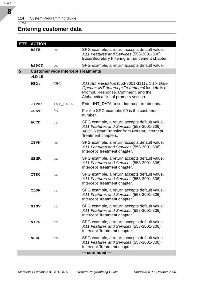
114 System Programming Guideof 206
Entering customer data
8T A S K 120
BSFE cr SPG example, a return accepts default value. X11 Features and Services (553-3001-306) Boss/Secretary Filtering Enhancement chapter.
ASPCT cr SPG example, a return accepts default value.
5 Customer wide Intercept Treatments>LD 15
REQ: CHG X11 Administration (553-3001-311) LD 15, Gate Opener: INT (Intercept Treatments) for details of Prompt, Response, Comment, and the Alphabetical list of prompts section.
TYPE: INT_DATA Enter INT_DATA to set Intercept treatments.
CUST 99 For the SPG example, 99 is the customer number.
ACCD cr SPG example, a return accepts default value. X11 Features and Services (553-3001-306) AC15 Recall: Transfer from Norstar, Intercept Treatment chapters.
CTVN cr SPG example, a return accepts default value. X11 Features and Services (553-3001-306) Intercept Treatment chapter.
MBNR cr SPG example, a return accepts default value. X11 Features and Services (553-3001-306) Intercept Treatment chapter.
CTRC cr SPG example, a return accepts default value. X11 Features and Services (553-3001-306) Intercept Treatment chapter.
CLDN cr SPG example, a return accepts default value. X11 Features and Services (553-3001-306) Intercept Treatment chapter.
NINV cr SPG example, a return accepts default value. X11 Features and Services (553-3001-306) Intercept Treatment chapter.
NITR cr SPG example, a return accepts default value. X11 Features and Services (553-3001-306) Intercept Treatment chapter.
NRES cr SPG example, a return accepts default value. X11 Features and Services (553-3001-306) Intercept Treatment chapter.— continued —
STEP ACTION
Meridian 1 Options 51C, 61C, 81C System Programming Guide Standard 6.00 October 2000

System Programming Guide 115of 206
Entering customer data
8T A S K
NBLK cr SPG example, a return accepts default value. X11 Features and Services (553-3001-306) Intercept Treatment chapter.
MFVO cr SPG example, a return accepts default value. X11 Features and Services (553-3001-306) Intercept Treatment Enhancements chapter.
MFVN cr SPG example, a return accepts default value. X11 Features and Services (553-3001-306) Intercept Treatment Enhancements chapter.
MFCG cr SPG example, a return accepts default value. X11 Features and Services (553-3001-306) Intercept Treatment Enhancements chapter.
LCKT cr SPG example, a return accepts default value. X11 Features and Services (553-3001-306) Lockout, DID Second Degree Busy, and MFE Signaling Treatments chapter.
RCLE cr SPG example, a return accepts default value. X11 Features and Services (553-3001-306) Total Redirection Count chapter.
CONG cr SPG example, a return accepts default value.
DLT cr SPG example, a return accepts default value. X11 Features and Services (553-3001-306) Line Lockout chapter.
LLT cr SPG example, a return accepts default value. X11 Features and Services (553-3001-306) AC15 Recall: Transfer from Norstar, and Off-Hook Alarm Security chapters.
DNDT cr SPG example, a return accepts default value. X11 Features and Services (553-3001-306) Do Not Disturb chapter.
6 Listed Directory Numbers on attendant consoles>LD 15
REQ: CHG X11 Administration (553-3001-311) LD 15, Gate Opener: LDN (Listed Directory Numbers) for details of Prompt, Response, Comment, and the Alphabetical list of prompts section.
TYPE: LDN_DATA Enter LDN_DATA to set Listed DN.
— continued —
STEP ACTION
Meridian 1 Options 51C, 61C, 81C System Programming Guide Standard 6.00 October 2000
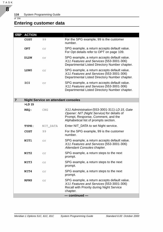
116 System Programming Guideof 206
Entering customer data
8T A S K 120
CUST 99 For the SPG example, 99 is the customer number.
OPT cr SPG example, a return accepts default value. For Opt details refer to OPT on page 109.
DLDN cr SPG example, a return accepts default value. X11 Features and Services (553-3001-306) Departmental Listed Directory Number chapter.
LDN0 cr SPG example, a return accepts default value. X11 Features and Services (553-3001-306) Departmental Listed Directory Number chapter.
ICI cr SPG example, a return accepts default value. X11 Features and Services (553-3001-306) Departmental Listed Directory Number chapter.
7 Night Service on attendant consoles>LD 15
REQ: CHG X11 Administration (553-3001-311) LD 15, Gate Opener: NIT (Night Service) for details of Prompt, Response, Comment, and the Alphabetical list of prompts section.
TYPE: NIT_DATA Enter NIT_DATA to set Night service.
CUST 99 For the SPG example, 99 is the customer number.
NIT1 cr SPG example, a return accepts default value. X11 Features and Services (553-3001-306) Attendant Consoles chapter.
NIT2 cr SPG example, a return steps to the next prompt.
NIT3 cr SPG example, a return steps to the next prompt.
NIT4 cr SPG example, a return steps to the next prompt.
RPNS cr SPG example, a return accepts default value. X11 Features and Services (553-3001-306) Recall with Priority during Night Service chapter.— continued —
STEP ACTION
Meridian 1 Options 51C, 61C, 81C System Programming Guide Standard 6.00 October 2000
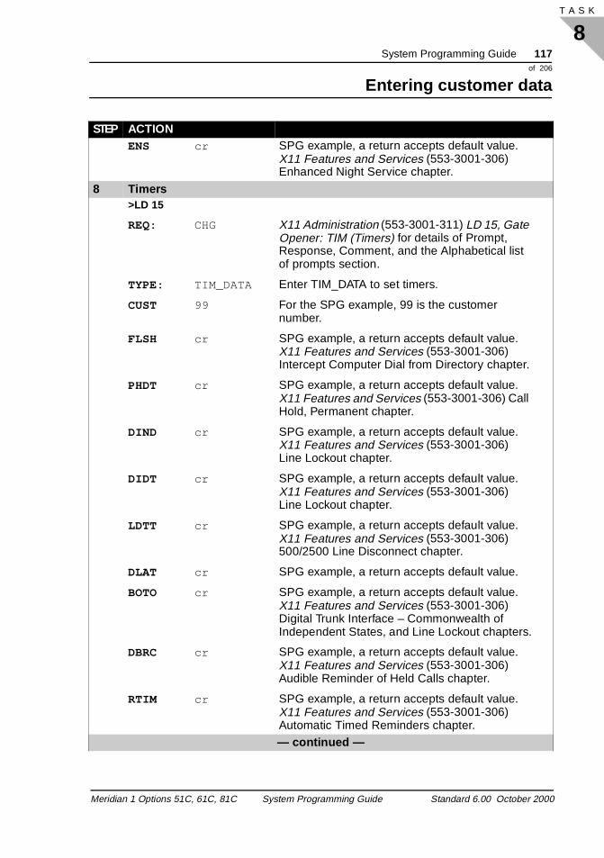
System Programming Guide 117of 206
Entering customer data
8T A S K
ENS cr SPG example, a return accepts default value. X11 Features and Services (553-3001-306) Enhanced Night Service chapter.
8 Timers>LD 15
REQ: CHG X11 Administration (553-3001-311) LD 15, Gate Opener: TIM (Timers) for details of Prompt, Response, Comment, and the Alphabetical list of prompts section.
TYPE: TIM_DATA Enter TIM_DATA to set timers.
CUST 99 For the SPG example, 99 is the customer number.
FLSH cr SPG example, a return accepts default value. X11 Features and Services (553-3001-306) Intercept Computer Dial from Directory chapter.
PHDT cr SPG example, a return accepts default value. X11 Features and Services (553-3001-306) Call Hold, Permanent chapter.
DIND cr SPG example, a return accepts default value. X11 Features and Services (553-3001-306) Line Lockout chapter.
DIDT cr SPG example, a return accepts default value. X11 Features and Services (553-3001-306) Line Lockout chapter.
LDTT cr SPG example, a return accepts default value. X11 Features and Services (553-3001-306) 500/2500 Line Disconnect chapter.
DLAT cr SPG example, a return accepts default value.
BOTO cr SPG example, a return accepts default value. X11 Features and Services (553-3001-306) Digital Trunk Interface – Commonwealth of Independent States, and Line Lockout chapters.
DBRC cr SPG example, a return accepts default value. X11 Features and Services (553-3001-306) Audible Reminder of Held Calls chapter.
RTIM cr SPG example, a return accepts default value. X11 Features and Services (553-3001-306) Automatic Timed Reminders chapter.— continued —
STEP ACTION
Meridian 1 Options 51C, 61C, 81C System Programming Guide Standard 6.00 October 2000
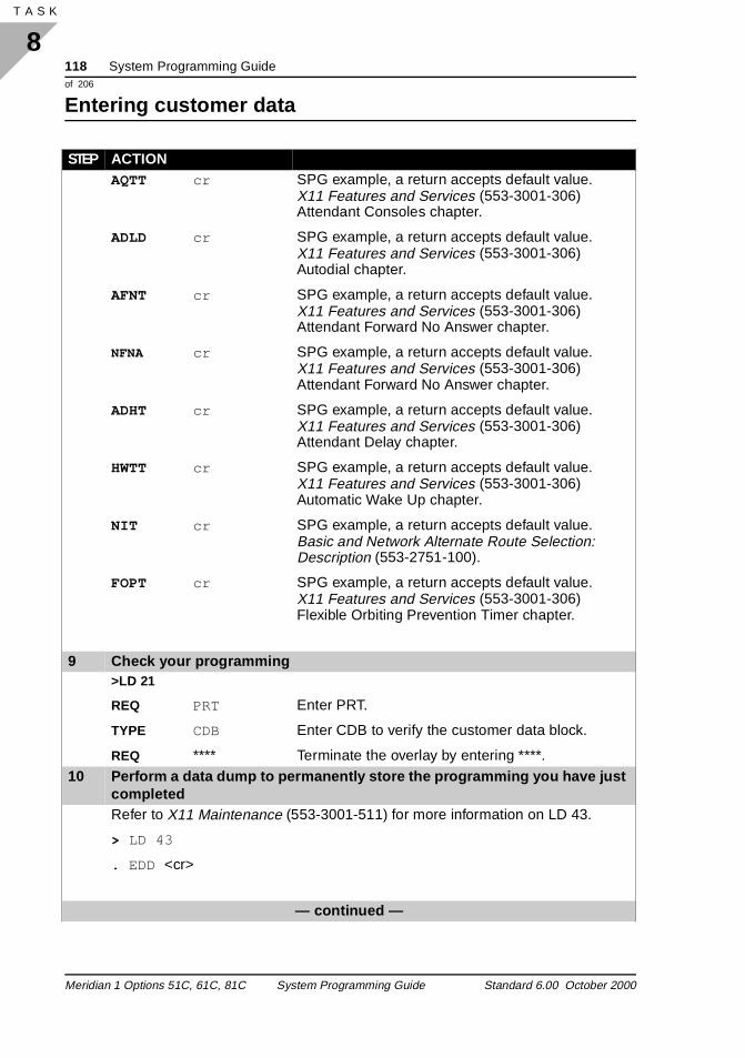
118 System Programming Guideof 206
Entering customer data
8T A S K 120
AQTT cr SPG example, a return accepts default value. X11 Features and Services (553-3001-306) Attendant Consoles chapter.
ADLD cr SPG example, a return accepts default value. X11 Features and Services (553-3001-306) Autodial chapter.
AFNT cr SPG example, a return accepts default value. X11 Features and Services (553-3001-306) Attendant Forward No Answer chapter.
NFNA cr SPG example, a return accepts default value. X11 Features and Services (553-3001-306) Attendant Forward No Answer chapter.
ADHT cr SPG example, a return accepts default value. X11 Features and Services (553-3001-306) Attendant Delay chapter.
HWTT cr SPG example, a return accepts default value. X11 Features and Services (553-3001-306) Automatic Wake Up chapter.
NIT cr SPG example, a return accepts default value. Basic and Network Alternate Route Selection: Description (553-2751-100).
FOPT cr SPG example, a return accepts default value. X11 Features and Services (553-3001-306) Flexible Orbiting Prevention Timer chapter.
9 Check your programming>LD 21
REQ PRT Enter PRT.
TYPE CDB Enter CDB to verify the customer data block.
REQ **** Terminate the overlay by entering ****.10 Perform a data dump to permanently store the programming you have just
completedRefer to X11 Maintenance (553-3001-511) for more information on LD 43.
> LD 43
. EDD <cr>
— continued —
STEP ACTION
Meridian 1 Options 51C, 61C, 81C System Programming Guide Standard 6.00 October 2000
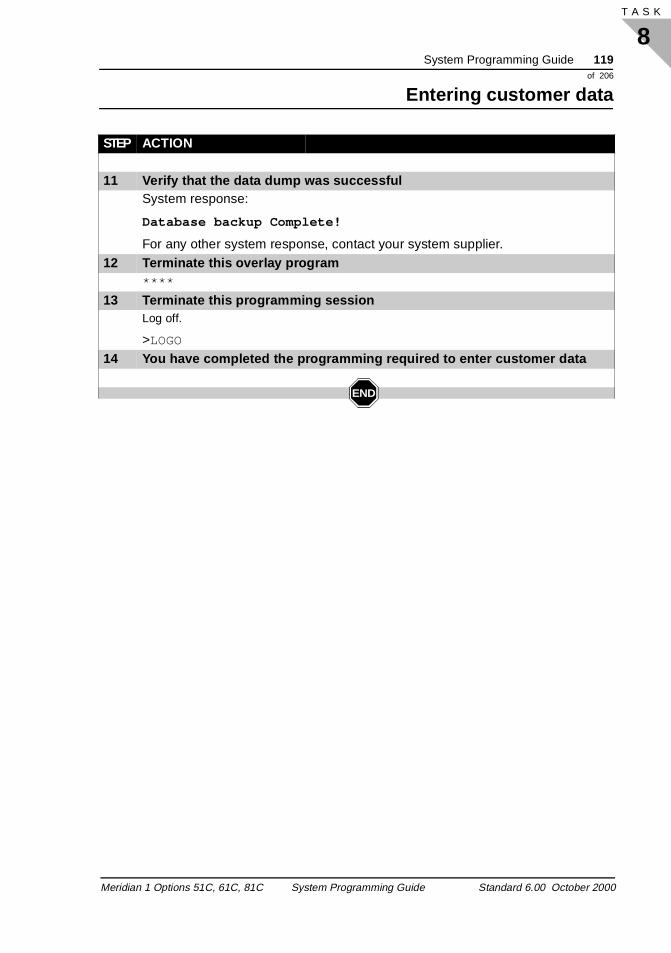
System Programming Guide 119of 206
Entering customer data
8T A S K
11 Verify that the data dump was successfulSystem response:
Database backup Complete!
For any other system response, contact your system supplier.12 Terminate this overlay program
****
13 Terminate this programming sessionLog off.
>LOGO
14 You have completed the programming required to enter customer data
END
STEP ACTION
Meridian 1 Options 51C, 61C, 81C System Programming Guide Standard 6.00 October 2000
120 System Programming Guideof 206
Entering customer data
8T A S K 120
Meridian 1 Options 51C, 61C, 81C System Programming Guide Standard 6.00 October 2000
System Programming Guide 121of 206
Setting up attendant consoles
9T A S K
out s any
ing.
cific
igh n es
ing
Setting up attendant consoles Attendant consoles
Task 9
Setting up sets and consoles
Attendant Consoles assist in placing and extending calls into andof the Meridian 1 system. The operator of an Attendant Console iknown as the attendant. The consoles provide the attendant with munique features that increase the speed and ease of call process
Refer to Attendant Consoles: Description (553-2201-117).
The attendant console, in its standard configuration, allows you toperform basic operator tasks. Options are available to enhance or customize the attendant console, tailoring it to meet customer speneeds.
Do not assign attendant consoles to high priority card slots. The hnumber of priority messages generated by attendant consoles caresult in delays, both in messages output to the attendant consolthemselves, and to messages output to telephones and trunks.
Always assign attendant consoles to card slots 2 - 10. Avoid assigna large number of attendant consoles to the same network loop.
Purpose
Attendant console features
Administration tips
Meridian 1 Options 51C, 61C, 81C System Programming Guide Standard 6.00 October 2000
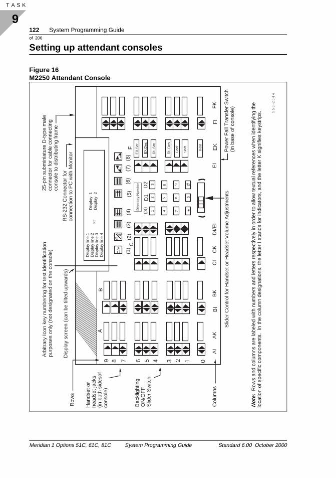
122 System Programming Guideof 206
Setting up attendant consoles
9T A S K 126
Figure 16M2250 Attendant Console
Dis
play
scr
een
(can
be
tilte
d up
war
ds)
Row
s
9 7 68 5 4 3 2 1 0
*1 4 7
2 5 8 0
3 6 9 #
AK
BK
CK
AI
BI
CI
DI/E
IE
IE
KF
IF
K
Hol
d
Shi
ft
Con
f
RL.
Des
RL.
Src
EX
.Des
EX
.Scr
RS
-232
Con
nect
or fo
rco
nnec
tion
to P
C w
ith M
onito
r
Slid
er C
ontr
ol fo
r H
ands
et o
r H
eads
et V
olum
e A
djus
tmen
ts
Bac
klig
htin
g O
N/O
FF
Slid
er S
witc
h
(1)
(2)
(3)
(4)
(5)
(6)
(7)
(8)
Arb
itrar
y Ic
on k
ey n
umbe
ring
for
test
iden
tific
atio
n pu
rpos
es o
nly
(not
des
igna
ted
on th
e co
nsol
e)
Col
umns
Pow
er F
ail T
rans
fer
Sw
itch
(in b
ase
of c
onso
le)
Han
dset
or
head
set j
acks
(in
bot
h si
deso
f co
nsol
e)
25-p
in s
ubm
inia
ture
D-t
ype
mal
eco
nnec
tor
for
cabl
e co
nnec
ting
cons
ole
to d
istr
ibut
ing
fram
e
Not
e: R
ows
and
colu
mns
are
labe
led
with
num
bers
and
lette
rs r
espe
ctiv
ely
in o
rder
to a
llow
text
ual r
efer
ence
s w
hen
iden
tifyi
ng th
e lo
catio
n of
spe
cific
com
pone
nts.
In
the
colu
mn
desi
gnat
ions
, the
lette
r I s
tand
s fo
r in
dica
tors
, and
the
lette
r K
sig
nifie
s ke
ystr
ips.
Dire
ctor
y N
umbe
r
Dis
play
line
1
Dis
play
line
2
Dis
play
line
3
Dis
play
line
4
55
3-2
04
4
C/H
C
D0
D1
D2
F
AB
Dis
play
1
Dis
play
2
or
Meridian 1 Options 51C, 61C, 81C System Programming Guide Standard 6.00 October 2000
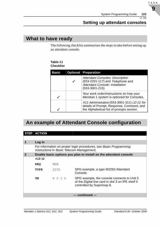
System Programming Guide 123of 206
Setting up attendant consoles
9T A S K
up
The following checklist summarizes the steps to take before settingan attendant console.What to have ready
Table 11 Checklist
Basic Optional Preparation
✓Attendant Consoles: Description (553-2201-117) and Telephone and Attendant Console: Installation (553-3001-215)
✓Your work order/instructions on how your Meridian 1 system is optioned for Consoles.
✓
X11 Administration (553-3001-311) LD 12, for details of Prompt, Response, Comment, and the Alphabetical list of prompts section.
An example of Attendant Console configuration
STEP ACTION
1 Log inFor information on proper login procedures, see Basic Programming Instructions in Basic Telecom Management.
2 Enable basic options you plan to install on the attendant console>LD 12
REQ NEW
TYPE 2250 SPG example, a type M2250 Attendant Console.
TN 8 0 3 5 SPG example, the console connects to Unit 5 of the Digital line card in slot 3 on IPE shelf 0 controlled by Superloop 8.
— continued —
Meridian 1 Options 51C, 61C, 81C System Programming Guide Standard 6.00 October 2000
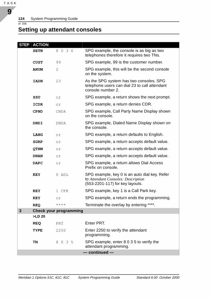
124 System Programming Guideof 206
Setting up attendant consoles
9T A S K 126
SETN 8 0 3 6 SPG example, the console is as big as two telephones therefore it requires two TNs.
CUST 99 SPG example, 99 is the customer number.
ANUM 2 SPG example, this will be the second console on the system.
IADN 23 As the SPG system has two consoles, SPG telephone users can dial 23 to call attendant console number 2.
SSU cr SPG example, a return shows the next prompt.
ICDR cr SPG example, a return denies CDR.
CPND CNDA SPG example, Call Party Name Display shown on the console.
DNDI DNDA SPG example, Dialed Name Display shown on the console.
LANG cr SPG example, a return defaults to English.
SGRP cr SPG example, a return accepts default value.
QTHM cr SPG example, a return accepts default value.
DNAN cr SPG example, a return accepts default value.
DAPC cr SPG example, a return allows Dial Access Prefix on console.
KEY 0 ADL SPG example, key 0 is an auto dial key. Refer to Attendant Consoles: Description (553-2201-117) for key layouts.
KEY 1 CPK SPG example, key 1 is a Call Park key.
KEY cr SPG example, a return ends the programming.
REQ **** Terminate the overlay by entering ****.3 Check your programming
>LD 20
REQ PRT Enter PRT.
TYPE 2250 Enter 2250 to verify the attendant programming.
TN 8 0 3 5 SPG example, enter 8 0 3 5 to verify the attendant programming.
— continued —
STEP ACTION
Meridian 1 Options 51C, 61C, 81C System Programming Guide Standard 6.00 October 2000
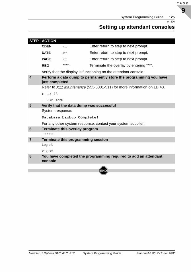
System Programming Guide 125of 206
Setting up attendant consoles
9T A S K
CDEN cr Enter return to step to next prompt.
DATE cr Enter return to step to next prompt.
PAGE cr Enter return to step to next prompt.
REQ **** Terminate the overlay by entering ****.
Verify that the display is functioning on the attendant console.4 Perform a data dump to permanently store the programming you have
just completedRefer to X11 Maintenance (553-3001-511) for more information on LD 43.
> LD 43
. EDD <cr>
5 Verify that the data dump was successfulSystem response:
Database backup Complete!
For any other system response, contact your system supplier.6 Terminate this overlay program
.****
7 Terminate this programming sessionLog off.
>LOGO
8 You have completed the programming required to add an attendant console
END
STEP ACTION
Meridian 1 Options 51C, 61C, 81C System Programming Guide Standard 6.00 October 2000
126 System Programming Guideof 206
Setting up attendant consoles
9T A S K 126
Meridian 1 Options 51C, 61C, 81C System Programming Guide Standard 6.00 October 2000
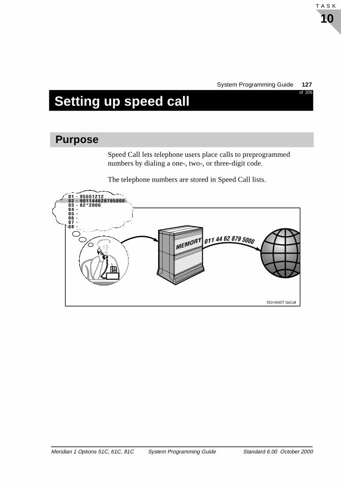
System Programming Guide 127of 206
Setting up speed call
10T A S K
Setting up speed callSpeed call
Task 10Task numberBasic configuration
Speed Call lets telephone users place calls to preprogrammed numbers by dialing a one-, two-, or three-digit code.
The telephone numbers are stored in Speed Call lists.
Purpose
553-0045T SpCall
01 - 9555121202 - 90114462879500003 - 82*200004 -05 -06 -07 -08 -
Meridian 1 Options 51C, 61C, 81C System Programming Guide Standard 6.00 October 2000
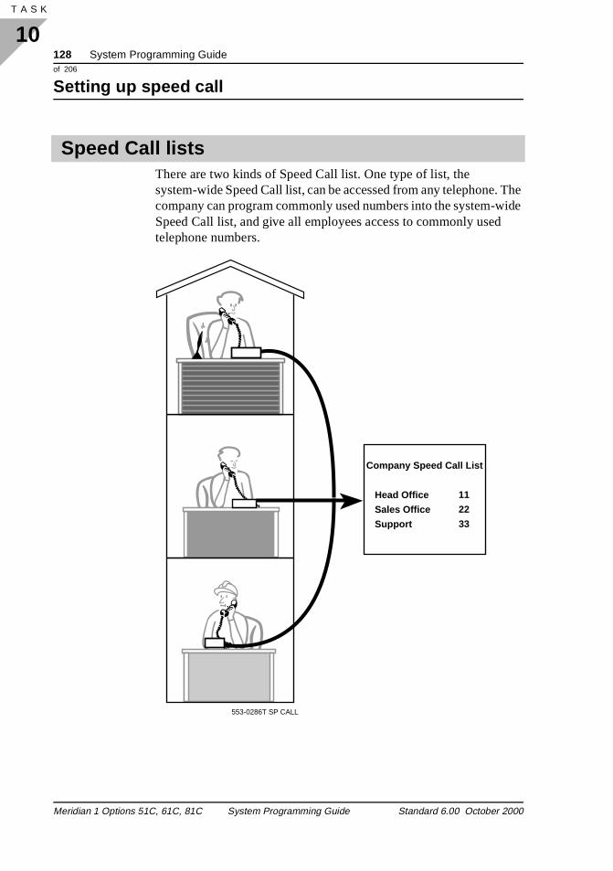
128 System Programming Guideof 206
Setting up speed call
10T A S K 136
. The ide
There are two kinds of Speed Call list. One type of list, the system-wide Speed Call list, can be accessed from any telephonecompany can program commonly used numbers into the system-wSpeed Call list, and give all employees access to commonly usedtelephone numbers.
Speed Call lists
553-0286T SP CALL
Company Speed Call List
Head Office
Sales Office
Support
11
22
33
Meridian 1 Options 51C, 61C, 81C System Programming Guide Standard 6.00 October 2000
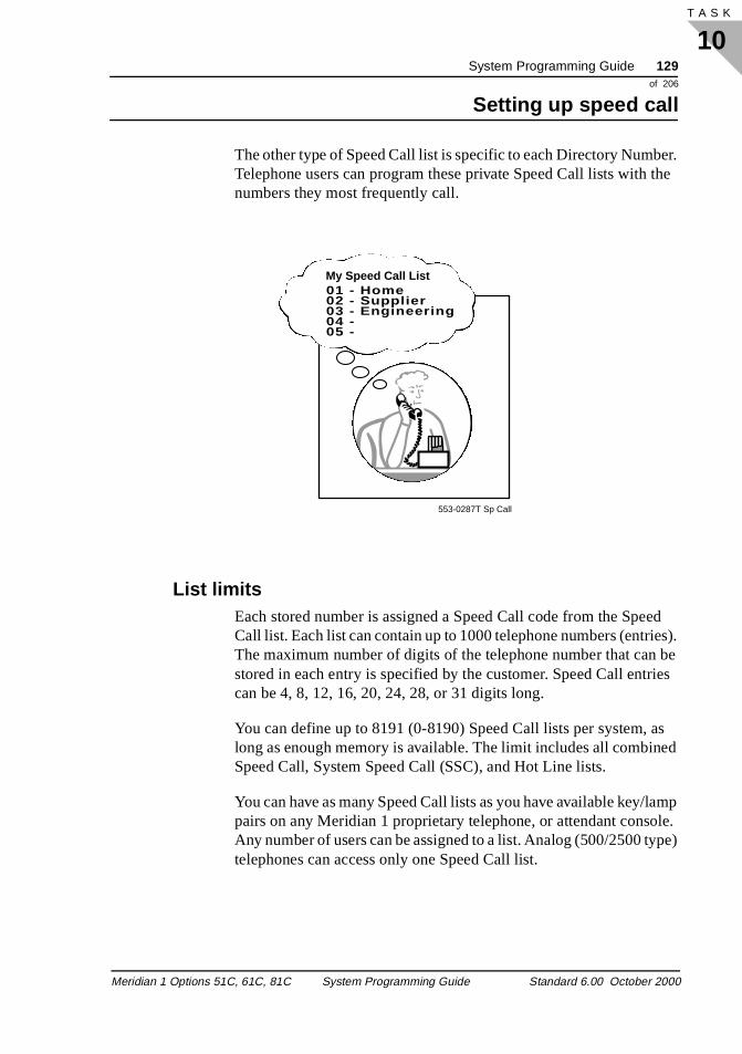
System Programming Guide 129of 206
Setting up speed call
10T A S K
er. the
ed es). be ies
s ed
amp le. pe)
The other type of Speed Call list is specific to each Directory NumbTelephone users can program these private Speed Call lists with numbers they most frequently call.
List limits Each stored number is assigned a Speed Call code from the SpeCall list. Each list can contain up to 1000 telephone numbers (entriThe maximum number of digits of the telephone number that canstored in each entry is specified by the customer. Speed Call entrcan be 4, 8, 12, 16, 20, 24, 28, or 31 digits long.
You can define up to 8191 (0-8190) Speed Call lists per system, along as enough memory is available. The limit includes all combinSpeed Call, System Speed Call (SSC), and Hot Line lists.
You can have as many Speed Call lists as you have available key/lpairs on any Meridian 1 proprietary telephone, or attendant consoAny number of users can be assigned to a list. Analog (500/2500 tytelephones can access only one Speed Call list.
01 - Home02 - Supplier03 - Engineering04 -05 -
My Speed Call List
553-0287T Sp Call
Meridian 1 Options 51C, 61C, 81C System Programming Guide Standard 6.00 October 2000
130 System Programming Guideof 206
Setting up speed call
10T A S K 136
an as
sers g nd
lists.
riate
212
fice
(*).
runk . For
A maximum of 31 digits for the telephone number is allowed per Speed Call list entry. An asterisk (*), which indicates a pause, andoctothorpe (#), which indicates end-of-dialing, can be programmedpart of the entry.
Speed Call list entries can be defined in LD 18 or by Speed Call Controllers (SCC). SCCs must know the digit length (one, two, orthree) required for the Speed Call codes in each list.
You can use Speed Call for both internal and external calls.
Programming and using listsSCCs can program numbers into the Speed Call list. Speed Call U(SCU) can use the Speed Call list. SCCs and SCUs can be analo(500/2500 type) telephones, Meridian 1 proprietary telephones, aattendant consoles.
Telephones designated as a SCUs cannot program numbers into
You can assign more than one SCC to each list, but it is not recommended.
Speed Call dialing To store an external number on a Speed Call list, enter the approptrunk group access code in front of the digits in the call.
For example, an external number in North America, such as 555-1is stored as 95551212.
Meridian 1 systems do not require a pause after a COT (Central OfTrunk) access code such as 9.
If a pause for dial tone is required between digits, use the asteriskThe * provides a 3 second pause between digits.
If the call is to be routed over to another type of system first, and outpulsed from there, that system might require a pause after the taccess code, before the other digits in the number are outpulsed
Speed call operation
Meridian 1 Options 51C, 61C, 81C System Programming Guide Standard 6.00 October 2000
System Programming Guide 131of 206
Setting up speed call
10T A S K
lse or
r as oes d
e.
lash
part nk ser
e
t to Call is
example, if you want to send calls over a TIE trunk and then outpudigits from the system at the other end, store the same number. Fexample, if 82 is the TIE trunk access code for the TIE trunks to another system and it is not an Meridian 1 system, store a numbe82*9*5551212. You can remove the pauses if the other system dnot require them. Experiment with the number of pauses you neeuntil you find a sequence of digits and pauses that works every tim
Store an octothorpe (#) at the end of the digits to indicate end of dialing. This speeds up outpulsing of the call.
The Speed Call key cannot be used after a Centrex Switchhook For during an established call to send digits out to the far site. TheSpeed Call key can be used only during the dialing stage.
PrivacyA telephone user can store a Calling Party Privacy (CPP) code asof a telephone number in the in the Speed Call list. An outgoing trucall, using the Speed Call code carries the Privacy Indicator. The ucannot dial *67 (or anything else) before accessing a Speed Call list entry.
Authorization codes If a Speed Call entry is programmed with a valid Authcode for Authcode Last followed by an octothorpe "#", the existing AuthcodLast operation will reject the Authcode as an invalid Authcode. If Authcode Last Retry is defined, the caller is reprompted for the Authcode.
Last Number Redial A number dialed using Speed Call will become the Last Number Redial number on all telephones except the M2317 and M3000.
Pretranslation A Speed Call List number should be programmed to allow for Pretranslation. For example, if 9 pretranslates to 99 and you wanreach 99 nxx xxxx, you need to program the number in the Speed List as 9 nxx xxxx. When the Speed Call List is used, 9 nxx xxxx pretranslated at call processing time to become 99 nxx xxxx.
Meridian 1 Options 51C, 61C, 81C System Programming Guide Standard 6.00 October 2000
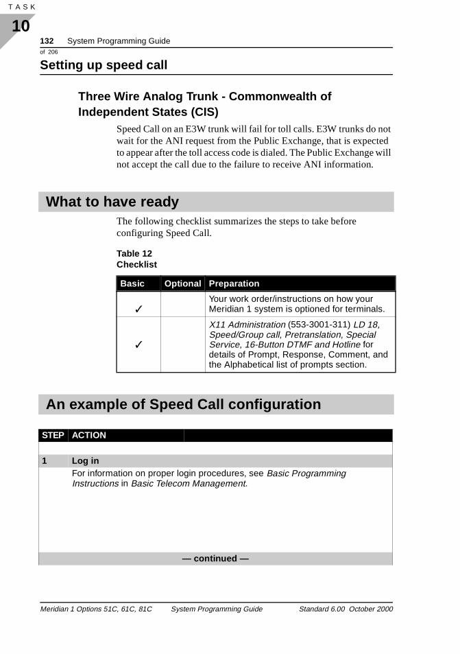
132 System Programming Guideof 206
Setting up speed call
10T A S K 136
t ed will
Three Wire Analog Trunk - Commonwealth of Independent States (CIS)
Speed Call on an E3W trunk will fail for toll calls. E3W trunks do nowait for the ANI request from the Public Exchange, that is expectto appear after the toll access code is dialed. The Public Exchangenot accept the call due to the failure to receive ANI information.
The following checklist summarizes the steps to take before configuring Speed Call.
What to have ready
Table 12 Checklist
Basic Optional Preparation
✓Your work order/instructions on how your Meridian 1 system is optioned for terminals.
✓
X11 Administration (553-3001-311) LD 18, Speed/Group call, Pretranslation, Special Service, 16-Button DTMF and Hotline for details of Prompt, Response, Comment, and the Alphabetical list of prompts section.
An example of Speed Call configuration
STEP ACTION
1 Log inFor information on proper login procedures, see Basic Programming Instructions in Basic Telecom Management.
— continued —
Meridian 1 Options 51C, 61C, 81C System Programming Guide Standard 6.00 October 2000
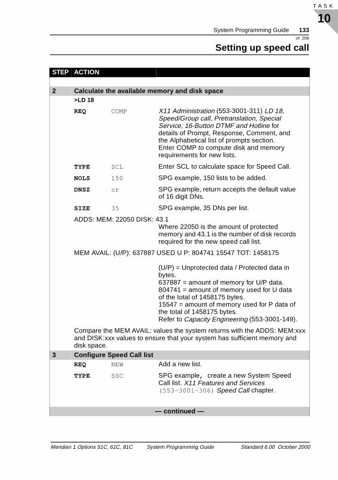
System Programming Guide 133of 206
Setting up speed call
10T A S K
2 Calculate the available memory and disk space>LD 18
REQ COMP X11 Administration (553-3001-311) LD 18, Speed/Group call, Pretranslation, Special Service, 16-Button DTMF and Hotline for details of Prompt, Response, Comment, and the Alphabetical list of prompts section.Enter COMP to compute disk and memory requirements for new lists.
TYPE SCL Enter SCL to calculate space for Speed Call.
NOLS 150 SPG example, 150 lists to be added.
DNSZ cr SPG example, return accepts the default value of 16 digit DNs.
SIZE 35 SPG example, 35 DNs per list.
ADDS: MEM: 22050 DISK: 43.1Where 22050 is the amount of protected memory and 43.1 is the number of disk records required for the new speed call list.
MEM AVAIL: (U/P): 637887 USED U P: 804741 15547 TOT: 1458175
(U/P) = Unprotected data / Protected data in bytes. 637887 = amount of memory for U/P data.804741 = amount of memory used for U data of the total of 1458175 bytes.15547 = amount of memory used for P data of the total of 1458175 bytes.Refer to Capacity Engineering (553-3001-149).
Compare the MEM AVAIL: values the system returns with the ADDS: MEM:xxx and DISK:xxx values to ensure that your system has sufficient memory and disk space.
3 Configure Speed Call listREQ NEW Add a new list.
TYPE SSC SPG example, create a new System Speed Call list. X11 Features and Services (553-3001-306) Speed Call chapter.
— continued —
STEP ACTION
Meridian 1 Options 51C, 61C, 81C System Programming Guide Standard 6.00 October 2000
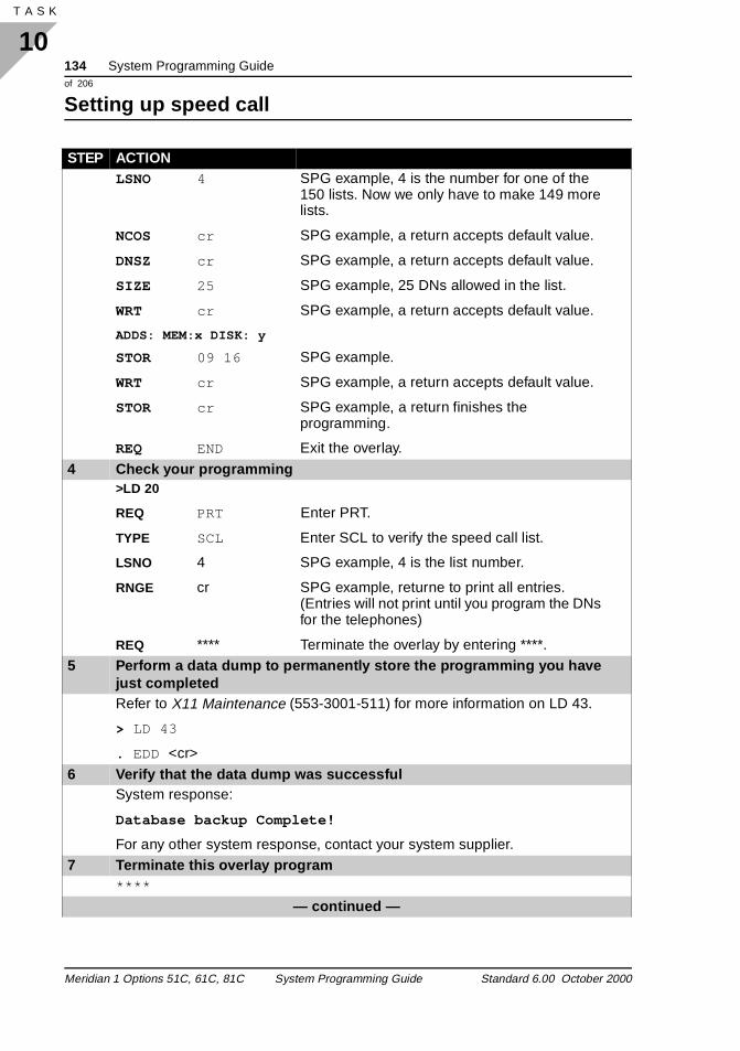
134 System Programming Guideof 206
Setting up speed call
10T A S K 136
LSNO 4 SPG example, 4 is the number for one of the 150 lists. Now we only have to make 149 more lists.
NCOS cr SPG example, a return accepts default value.
DNSZ cr SPG example, a return accepts default value.
SIZE 25 SPG example, 25 DNs allowed in the list.
WRT cr SPG example, a return accepts default value.
ADDS: MEM:x DISK: y
STOR 09 16 SPG example.
WRT cr SPG example, a return accepts default value.
STOR cr SPG example, a return finishes the programming.
REQ END Exit the overlay.
4 Check your programming>LD 20
REQ PRT Enter PRT.
TYPE SCL Enter SCL to verify the speed call list.
LSNO 4 SPG example, 4 is the list number.
RNGE cr SPG example, returne to print all entries. (Entries will not print until you program the DNs for the telephones)
REQ **** Terminate the overlay by entering ****.5 Perform a data dump to permanently store the programming you have
just completedRefer to X11 Maintenance (553-3001-511) for more information on LD 43.
> LD 43
. EDD <cr>
6 Verify that the data dump was successfulSystem response:
Database backup Complete!
For any other system response, contact your system supplier.7 Terminate this overlay program
****
— continued —
STEP ACTION
Meridian 1 Options 51C, 61C, 81C System Programming Guide Standard 6.00 October 2000
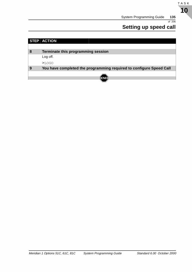
System Programming Guide 135of 206
Setting up speed call
10T A S K
8 Terminate this programming sessionLog off.
>LOGO
9 You have completed the programming required to configure Speed Call
END
STEP ACTION
Meridian 1 Options 51C, 61C, 81C System Programming Guide Standard 6.00 October 2000

136 System Programming Guideof 206
Setting up speed call
10T A S K 136
Meridian 1 Options 51C, 61C, 81C System Programming Guide Standard 6.00 October 2000
System Programming Guide 137of 206
Configuring tones
11T A S K
t for
the e
ned
l
s. ber
Configuring tonesTones
Task 11Configuring tones Configuring tones
Tones are used by the Meridian 1 and other telephone equipmensignalling. This equipment includes all 2500-type telephones andtrunks that send Digitone Multifrequency (DTMF) tones to the system, and by Multifrequency (MF) trunks that send MF tones to system. All 2500 sets and some trunks must have Class of Servic(CLS) defined as Digitone (DTN).
Configuring tones is your final task, and is only completed after 2500-type telephones and trunk requirements have been determifor the complete system. Refer to Capacity Engineering (553-3001-149) for details on calculating tone configuring requirements
Digitone receivers (DTR) are cards that are equipped on your Meridian 1 if you are using Digitone-type telephones or if your system connects to trunks that use Digitone signaling. The DTR interprets the Digitone tone signals, converting tones into a digitasignal that the Meridian 1 CPU can use.
DTRs are shared among all the Digitone-type telephones and trunkThe number of DTRs needed on your system depends on the numof Digitone-type telephones to be used, the number of Digitone signaling trunks, and the expected level of traffic.
Purpose
Digitone receivers
Meridian 1 Options 51C, 61C, 81C System Programming Guide Standard 6.00 October 2000
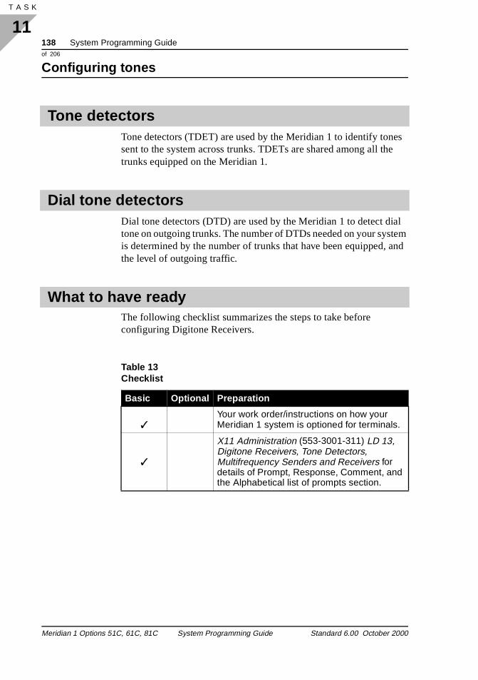
138 System Programming Guideof 206
Configuring tones
11T A S K 140
es e
al tem and
Tone detectors (TDET) are used by the Meridian 1 to identify tonsent to the system across trunks. TDETs are shared among all thtrunks equipped on the Meridian 1.
Dial tone detectors (DTD) are used by the Meridian 1 to detect ditone on outgoing trunks. The number of DTDs needed on your sysis determined by the number of trunks that have been equipped, the level of outgoing traffic.
The following checklist summarizes the steps to take before configuring Digitone Receivers.
Tone detectors
Dial tone detectors
What to have ready
Table 13 Checklist
Basic Optional Preparation
✓Your work order/instructions on how your Meridian 1 system is optioned for terminals.
✓
X11 Administration (553-3001-311) LD 13, Digitone Receivers, Tone Detectors, Multifrequency Senders and Receivers for details of Prompt, Response, Comment, and the Alphabetical list of prompts section.
Meridian 1 Options 51C, 61C, 81C System Programming Guide Standard 6.00 October 2000
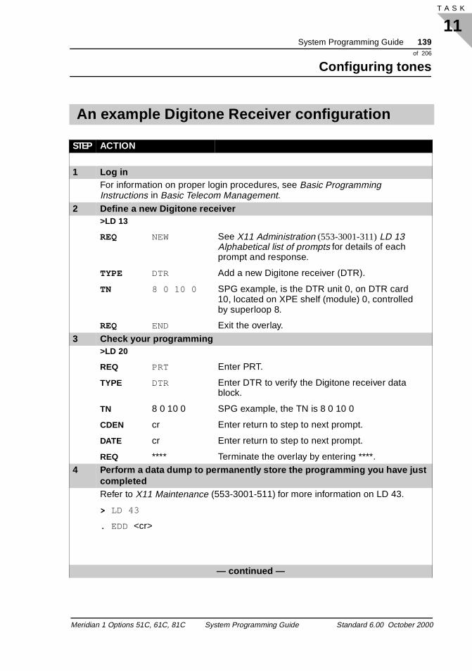
System Programming Guide 139of 206
Configuring tones
11T A S K
An example Digitone Receiver configuration
STEP ACTION
1 Log inFor information on proper login procedures, see Basic Programming Instructions in Basic Telecom Management.
2 Define a new Digitone receiver>LD 13
REQ NEW See X11 Administration (553-3001-311) LD 13 Alphabetical list of prompts for details of each prompt and response.
TYPE DTR Add a new Digitone receiver (DTR).
TN 8 0 10 0 SPG example, is the DTR unit 0, on DTR card 10, located on XPE shelf (module) 0, controlled by superloop 8.
REQ END Exit the overlay.
3 Check your programming>LD 20
REQ PRT Enter PRT.
TYPE DTR Enter DTR to verify the Digitone receiver data block.
TN 8 0 10 0 SPG example, the TN is 8 0 10 0
CDEN cr Enter return to step to next prompt.
DATE cr Enter return to step to next prompt.
REQ **** Terminate the overlay by entering ****.4 Perform a data dump to permanently store the programming you have just
completedRefer to X11 Maintenance (553-3001-511) for more information on LD 43.
> LD 43
. EDD <cr>
— continued —
Meridian 1 Options 51C, 61C, 81C System Programming Guide Standard 6.00 October 2000
140 System Programming Guideof 206
Configuring tones
11T A S K 140
5 Verify that the data dump was successfulSystem response:
Database backup Complete!
For any other system response, contact your system supplier.6 Terminate this overlay program
****
7 Terminate this programming sessionLog off.
>LOGO
8 You have completed the programming required to configure tones
END
STEP ACTION
Meridian 1 Options 51C, 61C, 81C System Programming Guide Standard 6.00 October 2000
System Programming Guide 141of 206
Setting up digital and ISDN trunks
12T A S K
res.
ork
r
and
e
. If
Setting up digital and ISDN trunks Digital trunks
Task 12
Setting up trunks
Digital trunks carry signaling and calls in a digital format between telephone switches. Digital trunks provide greater quality than analog trunks and allow the use of advanced signaling and network featu
The proper configuration of digital trunks is essential to your telephone network access and features. If trunks are not properlyprovisioned, users can have difficulty placing calls to destinationsserved by other telephone switches, or are unable to use the netwfeatures available to them. Refer to X11 Networking Features and Services (553-2901-301), ISDN PRI: Installation (553-2901-201), and ISDN PRI: Maintenance (553-2901-501).
Digital trunks can take many physical forms, including twisted paicable, channels on multiplexed cable, and fibre optic links. The provisioning in software of these different types of physical trunks arethe same. Configuration depends on the way a trunk will be used billed.
TrafficWhen planning to configure new trunks, consider the impact of thextra traffic load on the loop, or superloop, to which the trunk is connected. Loops and superloops perform best when they shareequally in the total traffic load offered to the system.
Blockage within the system will be negligible when the traffic loadper loop or superloop is kept within the recommended guidelinesall your existing loops and superloops are at their recommended
Purpose
Digital trunks
Meridian 1 Options 51C, 61C, 81C System Programming Guide Standard 6.00 October 2000
142 System Programming Guideof 206
Setting up digital and ISDN trunks
12T A S K 156
ill the
ks
s in
s.
ICA
capacity, consider adding more to your system (especially if you wbe adding more digitone receivers, telephones, or data terminals infuture).
Trunk types Japan Digital Multiplex InterfacesJapan Digital Multiplex Interface (JDMI) trunks provide connectivity between the Meridian 1 and other telephone switches. JDMI truncarry both incoming and outgoing calls.
1.5 Mbit/s DTI trunks 1.5 Mbit/s Digital Trunk Interface (DTI) trunks provide digital connectivity between the Meridian 1 and other telephone switchethe North American market. DTI trunks carry both incoming and outgoing calls.
2.0 Mbit/s DTI trunks 2.0 Mbit/s Digital Trunk Interface (DTI) trunks provide digital connectivity between the Meridian 1 and other telephone switcheDTI trunks carry both incoming and outgoing calls.
DTI trunk options Many trunk options exist. For detailed discussions of DTI trunk options and trunk provisioning, refer to the ISDN PRI: Installation (553-2901-201), and ISDN PRI: Maintenance (553-2901-501).
Signaling Category Select a Signaling Category table number by responding to the Sprompt in LD 14.
Channel order You can specify the order in which channels are allocated. To specify the channel order, respond to the INC prompt.
Meridian 1 Options 51C, 61C, 81C System Programming Guide Standard 6.00 October 2000
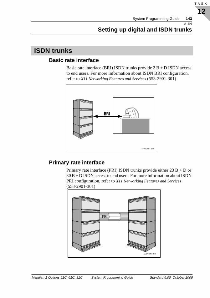
System Programming Guide 143of 206
Setting up digital and ISDN trunks
12T A S K
,
DN
Basic rate interfaceBasic rate interface (BRI) ISDN trunks provide 2 B + D ISDN access to end users. For more information about ISDN BRI configurationrefer to X11 Networking Features and Services (553-2901-301)
Primary rate interface Primary rate interface (PRI) ISDN trunks provide either 23 B + D or 30 B + D ISDN access to end users. For more information about ISPRI configuration, refer to X11 Networking Features and Services (553-2901-301)
ISDN trunks
553-0289T BRI
BRI
553-0288T PRI
PRI
Meridian 1 Options 51C, 61C, 81C System Programming Guide Standard 6.00 October 2000
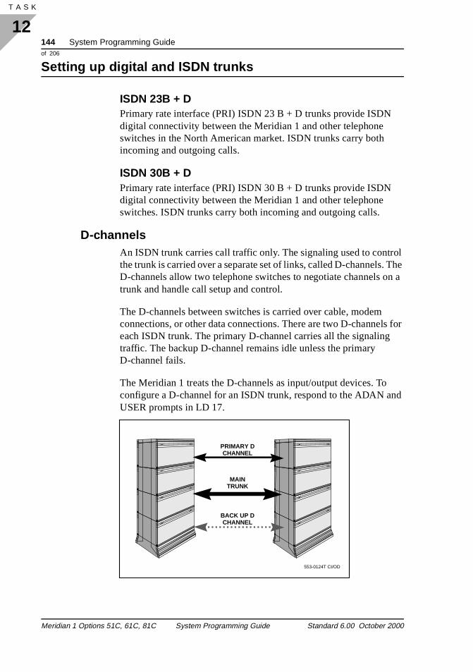
144 System Programming Guideof 206
Setting up digital and ISDN trunks
12T A S K 156
The n a
s for
nd
ISDN 23B + DPrimary rate interface (PRI) ISDN 23 B + D trunks provide ISDN digital connectivity between the Meridian 1 and other telephone switches in the North American market. ISDN trunks carry both incoming and outgoing calls.
ISDN 30B + DPrimary rate interface (PRI) ISDN 30 B + D trunks provide ISDN digital connectivity between the Meridian 1 and other telephone switches. ISDN trunks carry both incoming and outgoing calls.
D-channels An ISDN trunk carries call traffic only. The signaling used to controlthe trunk is carried over a separate set of links, called D-channels.D-channels allow two telephone switches to negotiate channels otrunk and handle call setup and control.
The D-channels between switches is carried over cable, modem connections, or other data connections. There are two D-channeleach ISDN trunk. The primary D-channel carries all the signalingtraffic. The backup D-channel remains idle unless the primary D-channel fails.
The Meridian 1 treats the D-channels as input/output devices. Toconfigure a D-channel for an ISDN trunk, respond to the ADAN aUSER prompts in LD 17.
PRIMARY DCHANNEL
MAINTRUNK
BACK UP DCHANNEL
553-0124T CI/OD
Meridian 1 Options 51C, 61C, 81C System Programming Guide Standard 6.00 October 2000
System Programming Guide 145of 206
Setting up digital and ISDN trunks
12T A S K
s. A s.
ber
the ty
nd
s of
e be t
,
et em.
Digital trunk routes operate in the same way as analog trunk routetrunk route carries all calls of a specific type between two switche
Some digital trunk options are described here. In addition, a numof trunk options described in the previous section apply.
Integrated Service Access RouteTo set a route up for Integrated Service Access (ISA), enter YES atISAR prompt in LD 16. You need to specify a route number, faciliindicator, and Service Identification at the RTN, FACY and SID prompts.
Set the minimum and maximum numbers of channels at the MIN aMAX prompts.
Specify the Network Class of Service group number and the ClasService at the PRIM, NCOS and COS prompts.
Select Trunk Group Access Restrictions at the TGAR prompt.
Network Attendant Service Network Attendant Service is a feature that allows attendants to bshared by Meridian 1 switches across a network. Calls that wouldnormally be routed to an attendant at a particular Meridian 1 can routed to an attendant at a different Meridian 1, even to a differenlocation, if the local attendant is unavailable.
To allow Network Attendant Service to operate over a trunk routerespond to the NASA prompt.
Digital trunk route options Protocol set group To select a protocol set, respond to the PGPN prompt. Protocol sgroups must already be defined in LD 27 before you can select th
Trunk routes
Meridian 1 Options 51C, 61C, 81C System Programming Guide Standard 6.00 October 2000
146 System Programming Guideof 206
Setting up digital and ISDN trunks
12T A S K 156
te.
C
on.
et
S
in -10
his r
t.
to he ree
Integrated Services Digital Network (ISDN) Enter YES at the ISDN prompt to make a trunk route an ISDN rouSpecify the mode of operation at the MODE prompt. Specify the DCHI port number at the DCHI prompt. Set the interface at the IFprompt.
Respond to the TRO prompt to enable or disable trunk optimizati
Priority designation You can specify a priority designation for DPNSS ISDN trunks. To sthe priority, respond to the PRIO prompt in LD 14.
Malicious Call Trace Enable or disable the Malicious Call Trace (MCT) signal at the MCTprompt in LD 16. Define the call trace request string at the MCCDprompt. Specify the digit string delay time at the MCDT prompt.
Set the MCT request timer at the MCTM prompt. This is the delaydisconnection that occurs when the far-end goes on-hook for AXED-channels.
Specify the MCT tandem disconnect delay at the MTND prompt. Tis the delay in disconnect operation at the node closest to the CO foAXE-10 interfaces.
Turn the MCT alarm on or off for external calls at the ALRM promp
Line identity options Set the Line Identities option by responding to the LID prompt in LD 16. Enter 0 to suppress the sending of ISDN Line Identities, 1send identities, or 2 to convert and then send identities. Specify tLine Identities conversion tree number at the LCNO prompt. (The tnumber is a DCNO tree defined in LD 49.)
Meridian 1 Options 51C, 61C, 81C System Programming Guide Standard 6.00 October 2000
System Programming Guide 147of 206
Setting up digital and ISDN trunks
12T A S K
Programming order for Meridian 1 to Central Office (DMS) PRI
Order Task Overlay
1 Defining error detection thresholds LD 73 Digital Data Block
2 Add a PRI loop LD 17 Configuration Record
3 Add a DCHI card LD 17 Configuration Record
4 Define a PRI customer LD 15 Customer Data Block
5 Define the PRI route LD 16 Route Data Block
6 Define the PRI B-channels (trunks) LD 14 Trunk Data Block
7 Define clock synchronization LD 73 Digital Data Block
An example of Meridian 1 to Central Office (DMS) PRI
STEP ACTION
1 Log inFor information on proper login procedures, see Basic Programming Instructions in Basic Telecom Management.
2 Define error detection thresholds>LD 73
REQ NEW See X11 Administration (553-3001-311) LD 73 Alphabetical list of prompts for details of each prompt and response.
TYPE DDB Enter DDB to configure the digital data block.— continued —
Meridian 1 Options 51C, 61C, 81C System Programming Guide Standard 6.00 October 2000
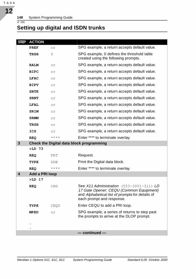
148 System Programming Guideof 206
Setting up digital and ISDN trunks
12T A S K 156
PREF cr SPG example, a return accepts default value.
TRSH 0 SPG example, 0 defines the threshold table created using the following prompts.
RALM cr SPG example, a return accepts default value.
BIPC cr SPG example, a return accepts default value.
LFAC cr SPG example, a return accepts default value.
BIPV cr SPG example, a return accepts default value.
SRTK cr SPG example, a return accepts default value.
SRNT cr SPG example, a return accepts default value.
LFAL cr SPG example, a return accepts default value.
SRIM cr SPG example, a return accepts default value.
SRMM cr SPG example, a return accepts default value.
TRSH cr SPG example, a return accepts default value.
ICS cr SPG example, a return accepts default value.
REQ **** Enter **** to terminate overlay.
3 Check the Digital data block programming>LD 73
REQ PRT Request.
TYPE DDB Print the Digital data block.
REQ **** Enter **** to terminate overlay.4 Add a PRI loop
>LD 17
REQ CHG See X11 Administration (553-3001-311) LD 17 Gate Opener: CEQU (Common Equipment) and Alphabetical list of prompts for details of each prompt and response.
TYPE CEQU Enter CEQU to add a PRI loop.
MPED cr SPG example, a series of returns to step past the prompts to arrive at the DLOP prompt.
.
.
— continued —
STEP ACTION
Meridian 1 Options 51C, 61C, 81C System Programming Guide Standard 6.00 October 2000
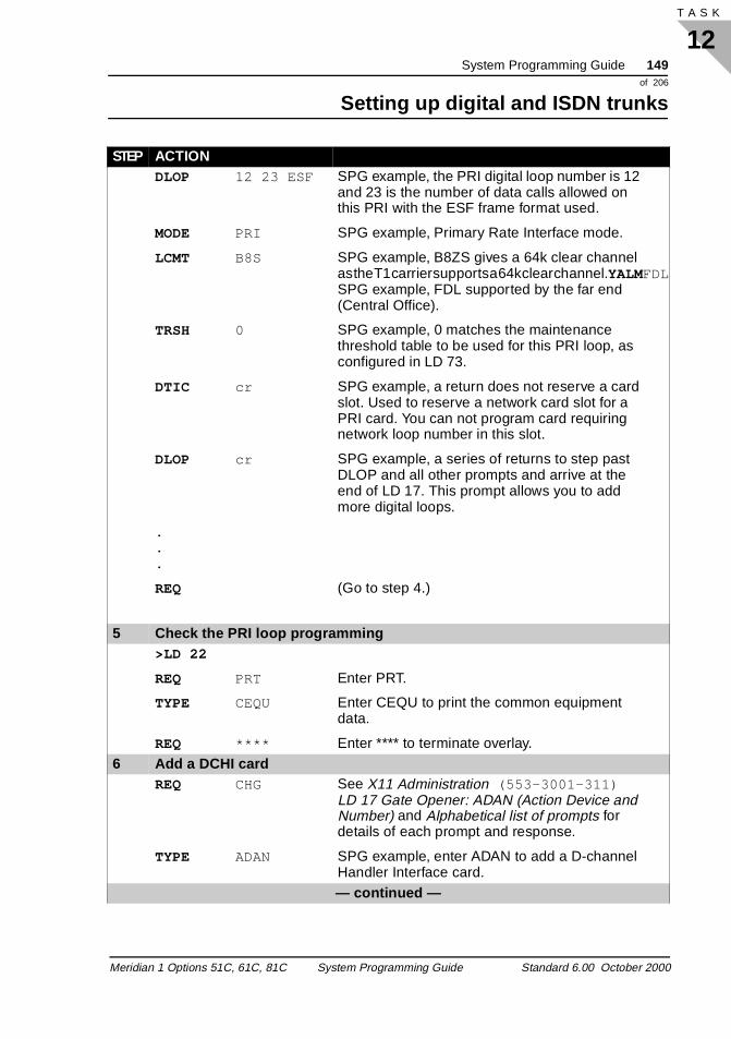
System Programming Guide 149of 206
Setting up digital and ISDN trunks
12T A S K
DLOP 12 23 ESF SPG example, the PRI digital loop number is 12 and 23 is the number of data calls allowed on this PRI with the ESF frame format used.
MODE PRI SPG example, Primary Rate Interface mode.
LCMT B8S SPG example, B8ZS gives a 64k clear channel as the T1 carrier supports a 64k clear channel.YALMFDLSPG example, FDL supported by the far end (Central Office).
TRSH 0 SPG example, 0 matches the maintenance threshold table to be used for this PRI loop, as configured in LD 73.
DTIC cr SPG example, a return does not reserve a card slot. Used to reserve a network card slot for a PRI card. You can not program card requiring network loop number in this slot.
DLOP cr SPG example, a series of returns to step past DLOP and all other prompts and arrive at the end of LD 17. This prompt allows you to add more digital loops.
.
.
.
REQ (Go to step 4.)
5 Check the PRI loop programming>LD 22
REQ PRT Enter PRT.
TYPE CEQU Enter CEQU to print the common equipment data.
REQ **** Enter **** to terminate overlay.6 Add a DCHI card
REQ CHG See X11 Administration (553-3001-311) LD 17 Gate Opener: ADAN (Action Device and Number) and Alphabetical list of prompts for details of each prompt and response.
TYPE ADAN SPG example, enter ADAN to add a D-channel Handler Interface card.— continued —
STEP ACTION
Meridian 1 Options 51C, 61C, 81C System Programming Guide Standard 6.00 October 2000
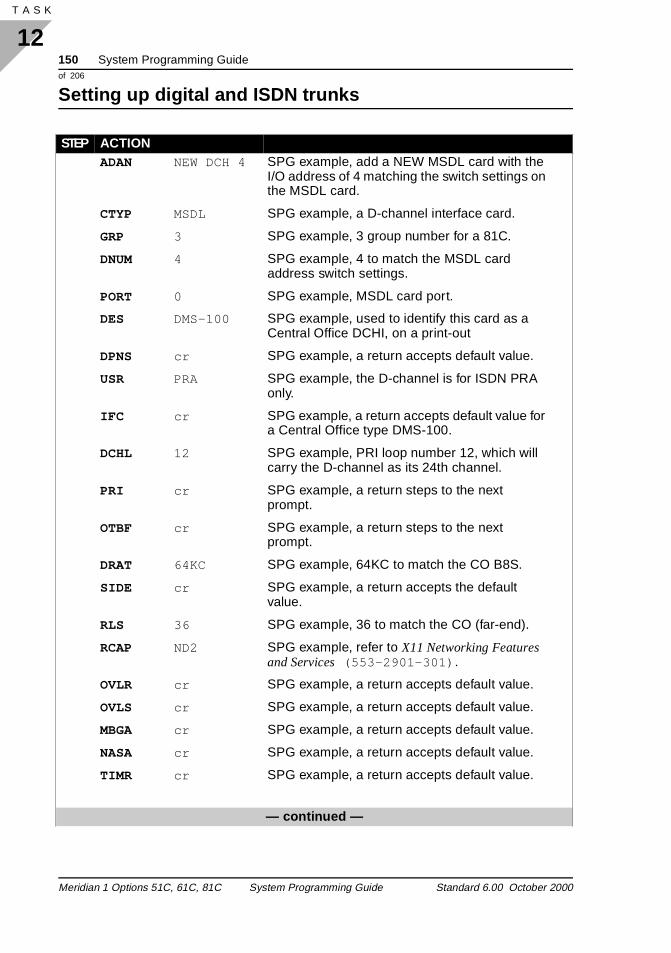
150 System Programming Guideof 206
Setting up digital and ISDN trunks
12T A S K 156
ADAN NEW DCH 4 SPG example, add a NEW MSDL card with the I/O address of 4 matching the switch settings on the MSDL card.
CTYP MSDL SPG example, a D-channel interface card.
GRP 3 SPG example, 3 group number for a 81C.
DNUM 4 SPG example, 4 to match the MSDL card address switch settings.
PORT 0 SPG example, MSDL card port.
DES DMS-100 SPG example, used to identify this card as a Central Office DCHI, on a print-out
DPNS cr SPG example, a return accepts default value.
USR PRA SPG example, the D-channel is for ISDN PRA only.
IFC cr SPG example, a return accepts default value for a Central Office type DMS-100.
DCHL 12 SPG example, PRI loop number 12, which will carry the D-channel as its 24th channel.
PRI cr SPG example, a return steps to the next prompt.
OTBF cr SPG example, a return steps to the next prompt.
DRAT 64KC SPG example, 64KC to match the CO B8S.
SIDE cr SPG example, a return accepts the default value.
RLS 36 SPG example, 36 to match the CO (far-end).
RCAP ND2 SPG example, refer to X11 Networking Features and Services (553-2901-301) .
OVLR cr SPG example, a return accepts default value.
OVLS cr SPG example, a return accepts default value.
MBGA cr SPG example, a return accepts default value.
NASA cr SPG example, a return accepts default value.
TIMR cr SPG example, a return accepts default value.
— continued —
STEP ACTION
Meridian 1 Options 51C, 61C, 81C System Programming Guide Standard 6.00 October 2000
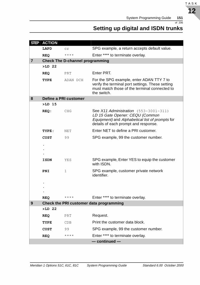
System Programming Guide 151of 206
Setting up digital and ISDN trunks
12T A S K
LAPD cr SPG example, a return accepts default value.
REQ **** Enter **** to terminate overlay.7 Check The D-channel programming
>LD 22
REQ PRT Enter PRT.
TYPE ADAN DCH For the SPG example, enter ADAN TTY 7 to verify the terminal port settings. These setting must match those of the terminal connected to the switch.
8 Define a PRI customer>LD 15
REQ: CHG See X11 Administration (553-3001-311) LD 15 Gate Opener: CEQU (Common Equipment) and Alphabetical list of prompts for details of each prompt and response.
TYPE: NET Enter NET to define a PRI customer.
CUST 99 SPG example, 99 the customer number.
.
.
.
ISDN YES SPG example, Enter YES to equip the customer with ISDN.
PNI 1 SPG example, customer private network identifier.
.
.
.
REQ **** Enter **** to terminate overlay.
9 Check the PRI customer data programming>LD 22
REQ PRT Request.
TYPE CDB Print the customer data block.
CUST 99 SPG example, 99 the customer number.
REQ **** Enter **** to terminate overlay.
— continued —
STEP ACTION
Meridian 1 Options 51C, 61C, 81C System Programming Guide Standard 6.00 October 2000
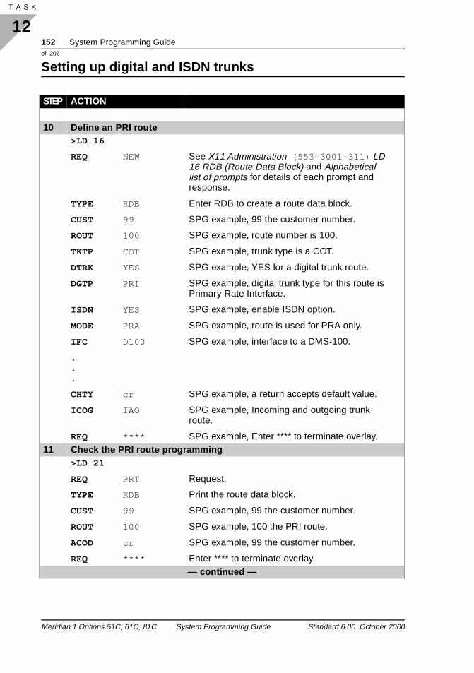
152 System Programming Guideof 206
Setting up digital and ISDN trunks
12T A S K 156
10 Define an PRI route>LD 16
REQ NEW See X11 Administration (553-3001-311) LD 16 RDB (Route Data Block) and Alphabetical list of prompts for details of each prompt and response.
TYPE RDB Enter RDB to create a route data block.
CUST 99 SPG example, 99 the customer number.
ROUT 100 SPG example, route number is 100.
TKTP COT SPG example, trunk type is a COT.
DTRK YES SPG example, YES for a digital trunk route.
DGTP PRI SPG example, digital trunk type for this route is Primary Rate Interface.
ISDN YES SPG example, enable ISDN option.
MODE PRA SPG example, route is used for PRA only.
IFC D100 SPG example, interface to a DMS-100.
.
.
.
CHTY cr SPG example, a return accepts default value.
ICOG IAO SPG example, Incoming and outgoing trunk route.
REQ **** SPG example, Enter **** to terminate overlay.11 Check the PRI route programming
>LD 21
REQ PRT Request.
TYPE RDB Print the route data block.
CUST 99 SPG example, 99 the customer number.
ROUT 100 SPG example, 100 the PRI route.
ACOD cr SPG example, 99 the customer number.
REQ **** Enter **** to terminate overlay.— continued —
STEP ACTION
Meridian 1 Options 51C, 61C, 81C System Programming Guide Standard 6.00 October 2000
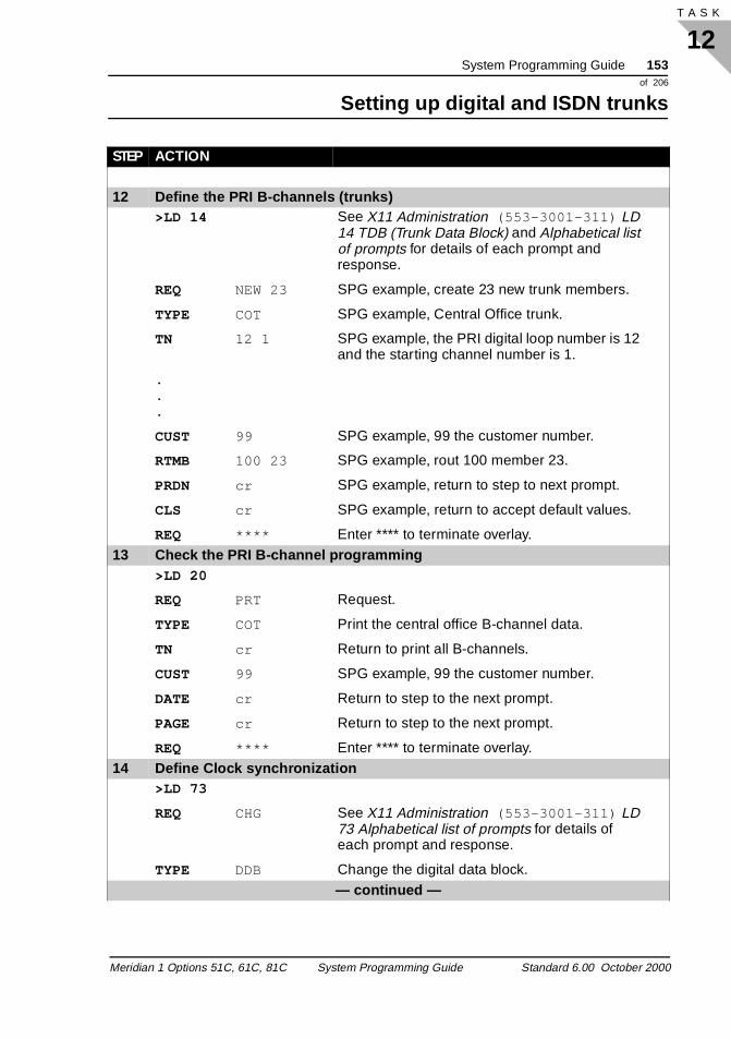
System Programming Guide 153of 206
Setting up digital and ISDN trunks
12T A S K
12 Define the PRI B-channels (trunks)>LD 14 See X11 Administration (553-3001-311) LD
14 TDB (Trunk Data Block) and Alphabetical list of prompts for details of each prompt and response.
REQ NEW 23 SPG example, create 23 new trunk members.
TYPE COT SPG example, Central Office trunk.
TN 12 1 SPG example, the PRI digital loop number is 12 and the starting channel number is 1.
.
.
.
CUST 99 SPG example, 99 the customer number.
RTMB 100 23 SPG example, rout 100 member 23.
PRDN cr SPG example, return to step to next prompt.
CLS cr SPG example, return to accept default values.
REQ **** Enter **** to terminate overlay.13 Check the PRI B-channel programming
>LD 20
REQ PRT Request.
TYPE COT Print the central office B-channel data.
TN cr Return to print all B-channels.
CUST 99 SPG example, 99 the customer number.
DATE cr Return to step to the next prompt.
PAGE cr Return to step to the next prompt.
REQ **** Enter **** to terminate overlay.14 Define Clock synchronization
>LD 73
REQ CHG See X11 Administration (553-3001-311) LD 73 Alphabetical list of prompts for details of each prompt and response.
TYPE DDB Change the digital data block.— continued —
STEP ACTION
Meridian 1 Options 51C, 61C, 81C System Programming Guide Standard 6.00 October 2000
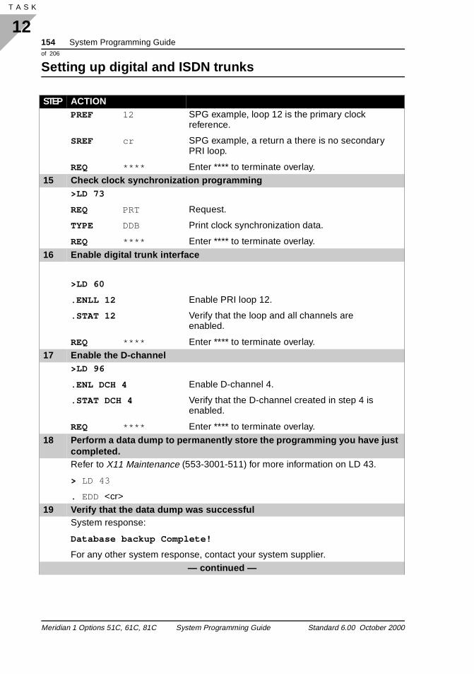
154 System Programming Guideof 206
Setting up digital and ISDN trunks
12T A S K 156
PREF 12 SPG example, loop 12 is the primary clock reference.
SREF cr SPG example, a return a there is no secondary PRI loop.
REQ **** Enter **** to terminate overlay.15 Check clock synchronization programming
>LD 73
REQ PRT Request.
TYPE DDB Print clock synchronization data.
REQ **** Enter **** to terminate overlay.
16 Enable digital trunk interface
>LD 60
.ENLL 12 Enable PRI loop 12.
.STAT 12 Verify that the loop and all channels are enabled.
REQ **** Enter **** to terminate overlay.17 Enable the D-channel
>LD 96
.ENL DCH 4 Enable D-channel 4.
.STAT DCH 4 Verify that the D-channel created in step 4 is enabled.
REQ **** Enter **** to terminate overlay.
18 Perform a data dump to permanently store the programming you have just completed.Refer to X11 Maintenance (553-3001-511) for more information on LD 43.
> LD 43
. EDD <cr>19 Verify that the data dump was successful
System response:
Database backup Complete!
For any other system response, contact your system supplier.— continued —
STEP ACTION
Meridian 1 Options 51C, 61C, 81C System Programming Guide Standard 6.00 October 2000
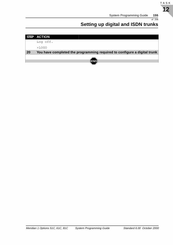
System Programming Guide 155of 206
Setting up digital and ISDN trunks
12T A S K
Log off.
>LOGO
20 You have completed the programming required to configure a digital trunk
END
STEP ACTION
Meridian 1 Options 51C, 61C, 81C System Programming Guide Standard 6.00 October 2000
156 System Programming Guideof 206
Setting up digital and ISDN trunks
12T A S K 156
Meridian 1 Options 51C, 61C, 81C System Programming Guide Standard 6.00 October 2000
System Programming Guide 157of 206
Setting up telephones
13T A S K
Setting up telephonesTelephones
Task 13
Refer to the Basic Telecom Management Guide to program telephones.
Meridian 1 Options 51C, 61C, 81C System Programming Guide Standard 6.00 October 2000

158 System Programming Guideof 206
Setting up telephones
13T A S K 158
Meridian 1 Options 51C, 61C, 81C System Programming Guide Standard 6.00 October 2000
System Programming Guide 159of 206
Terms and abbreviations
y is h ade
ry
d the
ne e the ne
t or
Basic Telecom Management
Terms and abbreviations
2500 set A push button analog Digitone ™ telephone. When a button or kepressed, the telephone transmits a combination of two tones whicrepresents the digit corresponding to the key pressed. Calls are mby pressing these buttons for the digits in the phone number to becalled.
500 setDial telephone, sometimes called a rotary telephone. It has a rotadevice on the front, used for the purpose of dialing digits to makecalls. Each time a person turns the dial with a finger in one of theholes, the dial returns to its rest position. In doing so, the circuit connecting the telephone to the system is broken and reconnectenumber of times marked beside the hole in the dial.
A-law compandingExcept for North America, companding is accomplished using a logarithmic law called, A-law. See companding.
Access RestrictionSometimes called the Class of Service of a telephone. It is only ocomponent of the Class of Service. Access-restriction controls thtypes of calls that can be made from a telephone. For example, ifaccess-restriction type is programmed as Toll Denied, the telephocannot be used to make any calls where the digit 1 or 0 is the firssecond digit following the access code digits.
There are many different access restriction types that have different levels of control of the types of calls that can be made from the telephone.
Meridian 1 Options 51C, 61C, 81C System Programming Guide Standard 6.00 October 2000
160 System Programming Guideof 206
Terms and abbreviations
194
st
d
ools
of s. 500 et,
to essor s are all
can o not
ACD (Automatic Call Distribution)Application software that puts incoming calls in a queue to one ormore telephones referred to as agent telephones. The longest-waitingcall is sent to the agent telephone that has been idle for the longetime. Incoming calls can be given a priority and answered at a prioritized telephone as an option. There are enhancements which can be added to basic ACD functionality to help with management anreporting tasks and also to customize and enhance the treatmentincoming calls are given. ACD software packages A, B, C, D, andCustom Controlled Routing offer enhancements to management tand reports, in order to add to the functionality of basic ACD.
Analog (500/2500 type) telephoneA name that replaces PBX set. The name describes a standard telephone set that works on many telephone systems. Examplesthese systems are the Meridian 1, DMS or other vendors systemAnalog (500/2500 type) telephone describes the North American set, United Kingdom analogue rotary dial, North American 2500 sUnited Kingdom MF 4 and Unity telephones.
application processorA special purpose computer that attaches to the Meridian 1 systemdecrease the load on the system processor. The application procprovides value-added and special services. Application processorused with voice mail, interactive voice response, and automatic cdistribution.
Aries telephonesDigital telephones called the M2006, M2008, M2216ACD, M2616telephones. They are also known as Meridian Modular Digital telephones.
AttendantThe main answering position on a system. From the attendant position, incoming calls are transferred to internal telephones. The terminal used at the attendant position is called a console. Therebe one or more attendants on a system, although some systems d
Meridian 1 Options 51C, 61C, 81C System Programming Guide Standard 6.00 October 2000
System Programming Guide 161of 206
Terms and abbreviations
e alls re
st
n be
ols
ally ed,
ne d 1
le.
ne
have any attendants. Attendants can answer incoming calls for thmain listed number, recall those which have not been answered, cfrom users who are dialing incorrectly, and calls from users who aattempting to place restricted calls.
Automatic Call Distribution (ACD)Application software that puts incoming calls in a queue to one ormore telephones referred to as agent telephones. The longest-waiting call is sent to the agent telephone that has been idle for the longetime. Incoming calls can be given a priority and answered at a prioritized telephone as an option. There are enhancements that caadded to basic ACD functionality to help with management and reporting tasks and also to customize and enhance the treatmentincoming calls are given. ACD software packages A, B, C, D, and Custom Controlled Routing offer enhancements to management toand reports, in order to add to the functionality of basic ACD.
Backup answering Otherwise known as Call Redirection, backup answering refers to call answering at a telephone or voice messaging port, when the origindialed caller is busy, not answering, or does not wish to be disturband features such as Call Forward are active.
Basic Rate Interface (BRI) An international standard for connecting terminals to a system. OBRI connection is composed of 2 B-channels at 64 kbit/s each, anD-channel at 16 kbit/s.
BCS set (Business Communication Set)A term for analog/digital hybrid telephones used on a Meridian 1 switch. The analog/digital hybrid telephones are no longer availab
BRI (Basic Rate Interface) An international standard for connecting terminals to a system. OBRI connection is composed of two B-channels at 64 kbit/s each, and one D-channel at 16 kbit/s.
Meridian 1 Options 51C, 61C, 81C System Programming Guide Standard 6.00 October 2000
162 System Programming Guideof 206
Terms and abbreviations
194
or
w the R
.
to
ies.
ly ed,
sets has
ient
Business Communication Set (BCS)Refer to BSC set.
Call CenterAnother term for a queue of incoming calls being answered by onemore telephones.
Call Detail Recording (CDR)CDR records are printed when calls are dialed. CDR records shoinformation about the number dialed, the telephones involved, andduration of the call. Additional information can be printed when CDenhancements are installed on a system.
Call PickupAlso called pickup or ringing number pickup. The feature that allows one user to answer an incoming call ringing at another telephone
call processingThe action of the processor executing the work schedule routine complete tasks controlled by telephone users. Call processing involves connecting telephone users to other telephones or facilit
Call RedirectionAlso known as backup answering, call redirection refers to calls answered at a telephone or voice messaging port when the originaldialed caller is busy, not answering, or does not wish to be disturband features like Call Forward are active.
call registerCall registers are located in a part of transient data memory. Callregisters store temporary information about trunks and telephone in the process of establishing calls. Each telephone or trunk in usea separate call register containing approximately 40 words of information. An example of the 40 words are Class of Service, features, and time slots in use. This information is known as transdata as it is held in a call register only for the duration of the call. Part of the call register information is transferred to the network or
Meridian 1 Options 51C, 61C, 81C System Programming Guide Standard 6.00 October 2000
System Programming Guide 163of 206
Terms and abbreviations
or ed,
ne. -On. e. If fter
ed u ed
er.
w
R
er
of a
superloop cards. When the information is transferred, the networksuperloop cards set up and control the call. When the call is finishthe transient data is erased from the call register.
Camp-OnThis feature allows an attendant to extend a call to a busy telephoThe user of the telephone hears a tone indicating a call is CampedWhen the user hangs up, the Camped-On call rings the telephonthe user does not hang up within a programmed amount of time ahearing the tone, the Camped-On call recalls to the attendant.
carriage returnAn instruction directing you to press the key on the keyboard markENTER, or RETURN. When you press the you tell the system yohave finished that line of input. In this book the symbol <cr> is usfor carriage return.
CCSA (Common Control Switching Arrangement)A service offered by AT&T for private networks that allows any telephone in the network to call another using a seven-digit numb
CDR (Call Detail Recording)CDR records are printed when calls are dialed. CDR records shoinformation about the number dialed, the telephones involved, and the duration of the call. Additional information can be printed when CDenhancements are installed on a system.
CE (Common Equipment)A term for the part of the system that controls the operation of othsystem components. Common equipment is composed of CPU, memory, input/output ports, and disk storage.
Central Office (CO) A large telephone switching system that provides service to subscribers located over a large geographic area, usually as partpublic or military switched telephone network. In North America a
Meridian 1 Options 51C, 61C, 81C System Programming Guide Standard 6.00 October 2000
164 System Programming Guideof 206
Terms and abbreviations
194
t
al
nts, ms
ce
. It and
. It is
am is in
central office is the facility containing the switching equipment thaprovides telephone service to subscribers in the immediate geographical area.
Central Office trunk (COT) Physical carrier of voice and data traffic to and from a local CentrOffice. Can be copper wire, cable, or optical fibre.
Central processing unit (CPU) The card that controls the functions of the other system componefollowing instructions it gets from the system memory. Some systehave one CPU and others have two.
CentrexA type of telephone system that usually resides in the central offiand can serve telephones distributed over a wide area. The Nortel Networks system that provides this functionality is called the DMSprovides services and features that are similar to those of a PBX some that are different.
channelA transmission path capable of carrying voice or data.
Class of Service There are many different capabilities and features that can be activated or deactivated for each telephone or trunk. A programming term is used to refer to these capabilities and features collectivelyis Class of Service. For example, the Last Number Redial featureactivated in the Class of Service.
Some people use the term Class of Service when they are referring to one particular feature called Access Restriction. When you progrTrunks, Meridian Mail channels, Authorization Codes, and DirectInward System Access ports, you assign a class of service which fact the access-restriction type.
Meridian 1 Options 51C, 61C, 81C System Programming Guide Standard 6.00 October 2000
System Programming Guide 165of 206
Terms and abbreviations
des
er
the
log e d
ulse
e
le
CO (Central Office) See Central Office.
CODEC (coder-decoder) A device that codes analog signals into digital signals. It also decodigital signals into analog signals.
Common Equipment (CE) A term for the part of the system that controls the operation of othsystem components. Common equipment is composed of CPU, memory, input/output ports, and disk storage.
compandingCompanding is derived from the words “compressing” and “expanding”. Companding is the process of compressing the amplitude range of a signal for transmission and then expanding signal back to its original form at the receiving end.
The transmitted signal (speech) is normally a digital signal. An anato digital conversion of speech is done in three steps. Sampling thanalog signal, Quantizing the sample, and Encoding the quantizesample.
The process of sampling, quantizing, and encoding is known as PCode Modulation (PCM). Eight bit PCM is an industry standard.
COMPANION™Meridian COMPANION ™ systems offer digital wireless telephoncapabilities to Meridian 1 systems. Wireless telephone users cantravel around their coverage area while answering, initiating, continuing, or transferring telephone calls using low-powered, pocket-size telephones.
CONF (Conference Card) The interface card in the system that is responsible for adding additional timeslots to an existing call so that more than two peopcan be bridged together for one call.
Meridian 1 Options 51C, 61C, 81C System Programming Guide Standard 6.00 October 2000
166 System Programming Guideof 206
Terms and abbreviations
194
ion
a
s
ant
rk
nts,
nd
configuration recordA programmable data block that describes the location and functof the CE hardware in the system. The configuration record is programmed in LD 17.
confirmation tone A form of special dial tone that indicates to a telephone user thatfeature has been activated.
CoreThe processing and data storage portion of the Meridian 1 Option51C, 61C, and, 81C systems. The Core equates to the Common Equipment in Meridian 1 systems.
Core numberThe Meridian 1 Options 61C, 81 and 81C systems has two redundCore systems. The two Core systems are identified by theCore numbers 0 and 1.
COT (Central Office trunk) A central office trunk is a circuit between a public exchange netwoswitch and a Meridian 1 system.
CPU (central processing unit) The card that controls the functions of the other system componefollowing instructions it receives from the system memory. Some older legacy systems had one CPU and others had two.
cross-connect panelSometimes called the jumper panel or main distribution frame (MDF). The panel where wires from telephones and trunks are interconnected with corresponding wires from the system’s line atrunk cards.
CSA trunkCommon Control Switching Arrangement trunk. See CCSA.
Meridian 1 Options 51C, 61C, 81C System Programming Guide Standard 6.00 October 2000
System Programming Guide 167of 206
Terms and abbreviations
and
r a nter lue the
Customer group A group of users with their own trunk groups, attendants, features Numbering Plan. A system can be used by one or more unique customer groups.
Data dump Storing information from memory onto disks.
DCE (Data Circuit Terminating Equipment)Devices that solve issues of interface between Data Terminating Equipment (DTE) and the network. Examples include modems, routers, channel service units, data service units, and interface cards.
DDI (Direct Dialing In) External callers dialing internal telephones directly, without the intervention of an attendant or interactive voice response system.
Default The response which is preprogrammed in the system software foprompt which must have a response. If the programmer does not eany value for this particular element or prompt, then the default vais retained in the database. These default responses, along with changed data, are shown when a printout is made. They are alsoexplained in the programming sections of this book and the otherprogramming guides available from Nortel Networks.
delay dialA trunk signal used to control the transfer of dialed digits. Upon seizure, the originating switch will not outpulse digits until the terminating switch does the following steps:
1. sends an off-hook to the originating switch
2. finds and attaches its digit collection equipment
3. sends an on-hook to the originating switch
Meridian 1 Options 51C, 61C, 81C System Programming Guide Standard 6.00 October 2000
168 System Programming Guideof 206
Terms and abbreviations
194
its. es.
d to had .
r, d
one, e gth. e er
sort
ent A
er gin
r on
The on-hook indicates the terminating switch can now accept digThe time between on-hook and off-hook varies with equipment typ
DensityA term that refers to the number of terminals that can be connectea card. Early vintages of cards such as line cards and trunk cardscapacities for fewer terminals than the cards that are made todayEarly cards are referred to as single density. Later cards are called double density to indicate that the capacity had doubled. Still latecards were introduced that are called quadruple (quad) density anoctal density.
Designator (DES)An alphanumeric code that a programmer associates with a telephif the system is equipped with Office Data Administration Softwarpackage 20 (ODAS). The code can be up to six characters in lenIt can be used to identify the telephone in some way that helps thprogrammer, usually for record keeping purposes. The programmdecides what the codes will be, and what they will mean.
Printouts can be made of telephones with specified DES codes tothe telephone database according to DES code parameters. For example, the DES system can be set up to identify what departmthe telephone is in and the floor and building where it is installed.telephone that is in the accounting department, and on floor 2 of building 1 can have a DES code which is ACF2B1. The programmcould request a printout of all telephones with DES codes that bewith the letters AC to find out what telephones belong to the accounting department.
Dial toneThe tone produced by the system after a user lifts the telephone handset to initiate a call. This tone is heard through the handset othe handsfree speaker, if the user is doing on-hook dialing. The user can dial a call when this tone is heard.
Meridian 1 Options 51C, 61C, 81C System Programming Guide Standard 6.00 October 2000
System Programming Guide 169of 206
Terms and abbreviations
to n
ted ta to by
are e.
one alls ber
DID (Direct Inward Dialing) External callers dialing internal telephones directly, without the intervention of an attendant or interactive voice response system.
DID trunkA trunking feature that allows telephone callers connected to the public exchange network to dial directly to a telephone connectedthe Meridian 1 system. DID happens without the intervention of aattendant or interactive voice system.
digital subscriber loopAny one of eight physical Basic Rate Interface (BRI) ports on a BRI line card. Each port has two B-channels and one D-channel.
digital telephonesA telephone that uses digital signaling. An analog voice is converinto a digital signal within the telephone. A Macintosh, IBM-PC orother data terminal can be connected to some telephones. The daand from that terminal is multiplexed on the same set of wires usedthe telephone for voice calls.
DigitoneTones used for signaling the digits 0 through 9, # and *. The tonesa combination of two voice frequencies, a high tone and a low ton
Digitone-type telephone An analog telephone that has buttons, on a key-pad, on the front.When each button is pressed, the telephone transmits a unique twhich represents the digit corresponding to the button pressed. Care made by pressing these buttons for the digits in the phone numto be called.
Direct Inward Dialing (DID) External callers dialing internal telephones directly, without the intervention of an attendant or interactive voice response system.
Meridian 1 Options 51C, 61C, 81C System Programming Guide Standard 6.00 October 2000
170 System Programming Guideof 206
Terms and abbreviations
194
ey
g a
hone
to
can om
data
Direct Inward System Access (DISA)A port configured to allow external callers to use the system as if thwere internal users.
Directory Number (DN)A telephone number. This is the number internal callers dial to rintelephone.
Disks Magnetic data storage media.
Distinctive RingingThere are three features that you can program that cause a telepto ring differently from default ringing.
You can use the feature called Distinctive Ringing to allow a userrecognize when a call from a particular trunk group is ringing a telephone. If this feature is activated on all trunk groups, then thetelephone rings distinctively whenever an external call comes in.
You can program digital telephones to ring in one of four differentringing styles called Distinctive Ringing Groups. This allows a user todifferentiate the various telephones when they ring.
You can program a telephone to ring distinctively when a call from a Dial Intercom Group member comes into the telephone. The userthen differentiate a call to a DN as opposed to an incoming call frthe intercom group.
DLC (Digital Line Card) An intelligent digital line card used on systems with Superloops. It can accommodate up to 16 digital telephones and 16 associatedterminals.
DN (Directory Number) A telephone number. This is the number callers dial to ring a telephone.
Meridian 1 Options 51C, 61C, 81C System Programming Guide Standard 6.00 October 2000
System Programming Guide 171of 206
Terms and abbreviations
he
Bus
s.
downloadTo receive data from another device.
DTE (Data Terminal Equipment)Equipment consisting of digital end devices that convert user information into data signals for transmission, and reconvert the received data signals into user information.
DTMFDual Tone Multi Frequency. See Digitone.
DTN (Digitone)A signaling system that uses audio tones to transmit information.Digitone signaling allows the transmission of digits 0-9, and on specially configured telephones, A-D.
DTR (Digitone receiver) A card with Digitone receiver units on it. The DTR units translate analog Digitone signals into a digital format.
Enhanced network A card accommodating two loops. Each loop has 32 timeslots.
exchange networkThe global network made up of telephone switches operated for tpublic by telephone utility companies and governments.
extender or extender pairA term used to describe a 3 Port Extender (3PE) card, SegmentedExtender (SBE) card, and the cable that connects them. These components extend the processor’s control to the network shelveThe SBE is located on the common equipment shelf, with the processor. The 3PE is located on the network shelf.
Meridian 1 Options 51C, 61C, 81C System Programming Guide Standard 6.00 October 2000
172 System Programming Guideof 206
Terms and abbreviations
194
e
ate.
ore ll ing. ic to
ne
s
nge ne
ve
y in e it he
oes
far endThe remote PBX at the distant end where your Tie trunk or Privatcircuit terminates.
Fast busy toneA tone that sounds like busy tone, but turns on and off at a faster rTypically, fast busy tone is used to indicate that a call is not progressing or cannot be completed. It can also be called overflow or reorder tone.
Features Capabilities assigned to the terminals that allow the users to do mthan make and receive basic calls. Features range from basic CaTransfer to something as complex as Network-wide Message WaitFeatures are provided by system software which is sometimes basevery system or packaged as separate options which are either chargeable or non-chargeable. In programming a regular telephothere is an element of programming referred to as the “feature prompt”. This element of programming controls certain capabilitiewhich can be activated for that telephone. Some capabilities are activated in the Class of Service.
FEX (Foreign exchange trunk)A trunk that provides telephone service to and from a public exchaswitch that is outside the subscriber’s exchange area. A user in ocity can dial the access code for his FEX trunk and receive dial tone from the foreign public exchange switch. The user can also receicalls dialed from the foreign exchange switch.
firmwareSoftware, data, and programming instructions stored permanentlRead Only Memory hardware. (It is neither soft nor hard, thereformust be firm.) Firmware provides the basic functions needed by tMeridian 1 system during start-up, software loading, and other periods when software is not be available in memory. Firmware dnot require regular update.
Meridian 1 Options 51C, 61C, 81C System Programming Guide Standard 6.00 October 2000
System Programming Guide 173of 206
Terms and abbreviations
e of .
a
in
are gned is
ged Call.
Flexible Features Codes User-defined numbers of up to four digits that can be used in placthe preprogrammed Special Prefix (SPRE) feature access codesFlexible Feature Codes allow users to define different feature access codes for different features.
Floppy disks Magnetic data storage media.
Foreign exchange trunk (FEX) The physical carrier of voice and data communications to and fromremote or foreign central office (exchange office).
GenericA family of software releases that are designed to apply to a certamarket or application. For example, the Generic called X11 was designed to be used in the North American business market. Thereother generics that have existed through the years that were desifor the European market and for the hospitality market. Now thereone generic of software for all markets.
groupA pair of interconnected network modules or shelves. A single network module or shelf is known as a half-group.
Group CallThe name of a feature that allows one user to press a key on a proprietary telephone and automatically call several telephones. When users answer these telephones they are automatically bridinto a conference connection with other users on the same Group
HandsetThe part of a telephone held in the hand to speak and listen. Thehandset contains the transmitter and receiver.
Meridian 1 Options 51C, 61C, 81C System Programming Guide Standard 6.00 October 2000
174 System Programming Guideof 206
Terms and abbreviations
194
ect eed
r a he
d or .
d
. For he to
Handsfree Using a telephone without requiring a handset or headset. Duringhandsfree operation, a properly equipped telephone picks up the user’s voice through a microphone built into the telephone, and broadcasts the far end user’s voice through a built-in speaker.
high-speed linkA communications channel that uses EIA RS422 or RS423 to connthe Meridian 1 to an applications processor. For example a high splink connects the Meridian 1 to the Meridian MAX.
immediate startA signal used on trunks to control the transfer of dialed digits. Aftetrunk seizure, the originating switch can start outpulsing digits to tterminating switch after a minimum delay of 70 ms.
Initialization During initialization, transient (unprotected) data is cleared from memory until the initialization is complete. During this time, established calls can remain connected. Calls cannot be originatedisconnected during this time. It generally lasts for a few seconds
Input/output (I/O) portsThe connection points through which the system outputs data anthrough which the system receives data.
intercept treatments Invalid or denied actions coming from a telephone, TIE trunk, attendant, or CCSA/DID trunk are given a treatment called an intercept treatment. These treatments are defined customer wideexample, if a user who is Toll Denied tries to dial a toll call, then tintercept treatment for that situation determines what will happenthat user. The user can hear overflow tone, or be routed to the attendant or can hear a recorded announcement.
Meridian 1 Options 51C, 61C, 81C System Programming Guide Standard 6.00 October 2000
System Programming Guide 175of 206
Terms and abbreviations
ch
and
nd
s, ue
nd
ctly
IPE (Intelligent Peripheral Equipment) The part of the system composed of interface cards that connect to terminals such as telephones and trunks, and the shelves on whithese cards reside. The interface cards are equipped with microprocessors.
ISDLC (Integrated Services Digital Line Card)Peripheral Equipment line cards that are used to support digital telephones. They can accommodate up to eight digital telephoneseight associated data terminals.
ISDN (Integrated Services Digital Network)A digital telephony network that allows the transmission of voice adata using internationally approved protocols.
IssueDuring development of a new release of software several versioncalled issues, of the release are developed in sequence. Each issfixes problems that have been identified from the previous issue.
Jumper panel Sometimes called the cross-connect panel or main distribution frame (MDF). The panel where wires from telephones and trunks are interconnected with corresponding wires from the system’s line atrunks cards.
junctorA passive device providing the interconnection for calls between network groups on multi-group Meridian 1 systems.
Key system A type of telephone system where the exchange lines can be direaccessed using keys or buttons on the telephones.
Meridian 1 Options 51C, 61C, 81C System Programming Guide Standard 6.00 October 2000
176 System Programming Guideof 206
Terms and abbreviations
194
re or r
nd of y
hen he
s
KeyA button on a proprietary telephone that you can assign as a featuDN function. Assign these keys using LD 11. The programming fothese keys is stored in the system memory.
legacy Hardware and software, supported on traditional Meridian 1 systems, not available on new systems.
LD Part of a title of an overlay program. For example, LD 10, a commaissued to the Meridian 1 to load program 10 into a reserved portionmemory, called the overlay area. Program 10 overlays a previousprogram in the overlay area. This is why LD 10 is called an overlaprogram. See Overlay.
link
1. Another name for a communications channel or circuit.
2. A button on certain types of telephones that users can press wthey want to perform a switch-hook flash, instead of pressing tswitch-hook under the handset.
3. A connection to another system, as in the Meridian Link application.
Loop A transmission path within the system. Line cards and trunk cardshare the transmission path using 32 timeslots.
low-speed linkA communications channel, using EIA RS232 to connect the Meridian 1 to a terminal.
Meridian 1 Options 51C, 61C, 81C System Programming Guide Standard 6.00 October 2000
System Programming Guide 177of 206
Terms and abbreviations
anel
for ll
anel
the
the
Main Distribution Frame (MDF) Sometimes called the cross-connect panel or jumper panel. The pwhere wires from telephones and trunks are interconnected with corresponding wires from the system’s line and trunk cards.
MARP (Multiple Appearance Directory Number Redirection Prime)
The telephone designated as the controlling one on a shared DNfeatures like Hunting, Call Forward No Answer, and Call Forward ACalls.
MCA (Meridian Communications Adapter) A device that provides an interface between an IBM-PC, Macintosh, or data terminal, and an Aries telephone.
MCU (Meridian Communications Unit) A device that provides an interface between an IBM-PC, Macintosh, or data terminal, and the Meridian 1 system.
MDF (main distribution frame) Sometimes called the cross-connect panel or jumper panel. The pwhere wires from telephones and trunks are interconnected with corresponding wires from the system’s line and trunks cards.
MEM (memory)The hardware in the system that is used to store the information system needs in order to operate.
memory (MEM)The hardware in the system that is used to store the information system needs in order to operate.
Meridian 1 telephoneA term used to describe a telephone set designed to operate exclusively with the Meridian 1 PBX. Refer to the Meridian 1 Telephones: Description and Specifications (553-3001-108) NTP.
Meridian 1 Options 51C, 61C, 81C System Programming Guide Standard 6.00 October 2000
178 System Programming Guideof 206
Terms and abbreviations
194
n
ly on
s to are
be ases U trol hits mp 2.
of a al is
Meridian Mail The voice mail system manufactured by Nortel Networks to be compatible with the Meridian 1. Meridian Mail is provided using aexternal application processor.
Meridian Proprietary Telephone A term used to describe telephones designed to operate exclusiveMeridian 1 switches.
Message Center A configuration where telephones are programmed to redirect calleither a specific telephone, the attendant, or voice mail when callsnot answered or the telephone was busy.
mnemonicA code used as a memory aid. Mnemonic codes are also used inprogramming.
module
1. Another name for a memory card.
2. An aluminum box that holds a card cage. It is also called a Universal Equipment Module or UEM.
MPU (Multi Processing Unit)A processor that performs some of the tasks that would otherwiseperformed by the CPU. For example, the IPE analog line card contins an MPU that interprets a series of on-hook, off-hook rotary dial pulas a DN. The MPU then passes the DN on to the CPU, saves CPresources. Without the MPU, the CPU would have to set and contimers to ensure the incoming pulses are not hook-switch flashes,on the line, or that the caller has abandoned the call. See time sta
Mu-law compandingCompanding is the process of compressing the amplitude range signal for transmission. At the receiving end the compressed signexpanded back to its original form. Companding is a contraction of
Meridian 1 Options 51C, 61C, 81C System Programming Guide Standard 6.00 October 2000
System Programming Guide 179of 206
Terms and abbreviations
ed
for ll
or
key are
to
the
igit of his
compressing and expanding. In North America, companding is accomplished using a logarithmic law called, “255 Law CompandPulse Code Modulation Digital Coding Standard” or µ-law. See companding.
Multiple Appearance Directory Number Redirection Prime (MARP)
The telephone designated as the controlling one on a shared DNfeatures like Hunting, Call Forward No Answer, and Call Forward ACalls.
Multiple Appearance DN A DN that is programmed to appear on more than one telephonemore than one key on one telephone.
Multiple Call DN A DN that appears on more than one telephone or more than oneon one telephone. It is capable of handling as many calls as thereappearances.
NANP (North American Numbering Plan) The North American Public Exchange Network has been divided ingeographical areas with three digit codes which precede the seven digit local telephone number of the subscriber. Previous to 1995, three digit area codes assigned to each geographical area were in the format where the first digit was any digit between 2-9 and the last dwas any digit between 0-9. The middle digit was either 0 or 1. AsJanuary 1, 1995, the middle digit can be any digit between 0-9. Tincreases the capacity of three digit codes available.
NE (Network Equipment) The part of the Meridian 1 that serves to interconnect terminal equipment. Network Equipment also provides services such as conferencing and tones.
Meridian 1 Options 51C, 61C, 81C System Programming Guide Standard 6.00 October 2000
180 System Programming Guideof 206
Terms and abbreviations
194
it
nto n ing 205 ode, ber.
re
lled
near endThe local Meridian 1 system where your Tie trunk or Private circuterminates.
NET (Network Controller - Superloop) The circuit pack on which the Superloop resides.
Network Class of Service A class of service that determines network access.
Network Equipment (NE) The part of the Meridian 1 that serves to interconnect terminal equipment. Network Equipment also provides services such as conferencing and tones.
NPA (Numbering Plan Area Code) The North American Public Exchange Network has been divided igeographical areas with three digit codes which precede the sevedigit local telephone number of the subscriber. It is used when diala long distance call. For example, when someone in a city in the area code wants to direct dial someone located in the 613 area cthey dial 1613 followed by the person’s seven digit telephone num
NTP (Nortel Networks Technical Publication)The manuals published by Nortel Networks that describe how to install, program and maintain all the features, services and components of a Meridian 1 system. Many of these manuals are shipped with every system. Some of the manuals are optional.
Numbering Plan The leading digits which are assigned to directory numbers, trunkroute access codes, and the Special Prefix (SPRE) code for featuactivation within one customer group database. The same digits cannot be assigned to two different numbers or codes. This is cathe “leftwise unique rule”.
Meridian 1 Options 51C, 61C, 81C System Programming Guide Standard 6.00 October 2000
System Programming Guide 181of 206
Terms and abbreviations
nd ign ation
to al
For example, it is permissible to have access code 11 for SPRE aaccess code 130 for paging trunks but it is not permissible to assaccess code 55 to a TIE trunk route and access code 552 to a dicttrunk route.
A typical Numbering Plan:
– 0 Attendant
– 11 Special Prefix Code (SPRE)
– 2xxxDirectory numbers (DNs)
– 3xxxDID Directory numbers
– 4 Unassigned (for future use)
– 5 Unassigned (for future use)
– 6 Unassigned (for future use)
– 7x Access codes for TIE trunks, paging trunks, dictation trunks
– 8 Access code to Automatic Route Selection calls
– 9 Access code to COT trunks or local calls
NXX (Public Network Exchange code) The first three digits of a seven digit telephone number assigned each subscriber in North America. These digits identify the CentrOffice to which the subscriber is connected.
Off-hookThe status of a telephone when the handset is lifted from the switch-hook. The telephone is described as being in an off-hook condition.
Meridian 1 Options 51C, 61C, 81C System Programming Guide Standard 6.00 October 2000
182 System Programming Guideof 206
Terms and abbreviations
194
ing
ng to
The
office dataA term used to describe the data programmed on a Meridian 1 usthe Administration overlay loads. The administration loads are asfollows:
� LD 10 to LD 29
� LD 49 to LD 52
� LD 56 to LD 58
� LD 73 to LD74
� LD79
� LD 81 to LD 88
� LD 90
� LD 93 to LD 95
� LD 97
On-hookThe status of a telephone when the handset is resting on the switch-hook. The telephone is described as being in an on-hook condition.
OutpulseTo transmit digits on external trunks to other systems. Also, telephones can outpulse digits to the system to which they are connected. The user causes either one of these types of outpulsioccur by dialing digits on a telephone.
output bufferA storage area in transient data memory used to keep output information to be sent to a telephone or trunk from the processor. information, called a messout, will control relays on trunk cards, LEDs or LCDs on telephones, and so on. There are two types of output buffers, SL-1 and 500.
Meridian 1 Options 51C, 61C, 81C System Programming Guide Standard 6.00 October 2000
System Programming Guide 183of 206
Terms and abbreviations
ate.
y or
s ys, e
and nd
t is . ors
ch
Overflow Tone A tone that sounds like busy tone, but turns on and off at a faster rTypically, fast busy tone is used to indicate that a call is not progressing or cannot be completed. It can also be called fast busreorder tone.
OverlayOverlay refers to administration and maintenance programs. Overlayare identified by the letters LD and numbers. Administration overlafor example LD 11, LD 17, and LD 83, allow data entry to customizMeridian 1 system features, telephones, trunk groups, hardware,data devices. Maintenance overlays, for example LD 32, LD 45, aLD 143, diagnose Meridian 1 system operation and faults.
parametersA range or limits set for entries in the software.
PBX (Private Branch Exchange) A private telephone switch that serves trunks and telephones.
PBX setA term replaced by Analog (500/2500 type) telephone. A PBX sea standard telephone set that works on many telephone systemsExamples of these systems are the Meridian 1, DMS or other vendsystems.
PCMPulse Code Modulation. See companding.
PE (Peripheral Equipment) The part of the system composed of interface cards that connect to terminals such as telephones and trunks, and the shelves on whithese cards reside.
Meridian 1 Options 51C, 61C, 81C System Programming Guide Standard 6.00 October 2000
184 System Programming Guideof 206
Terms and abbreviations
194
cy e PU
wer
RI one
PFTUPower Fail Transfer Unit. A term used for QUA4, QUA5, QUA6 andNT8D39 (DEES) transfer units. The term implies that an emergentransfer will only result from a loss of power. All transfer units can bconnected to perform the emergency transfer function when the Ccannot process calls, due to a system reload or CPU failure.
Phantom DN A DN which appears on a secondary key of a telephone. It is not published.
Phantom TN A TN defined in software that does not exist in hardware.
Pickup Also called call pickup, ringing number pickup. The feature that allows one user to answer an incoming call ringing at another telephone.
Pickup groupsA group of telephones provided to users who have to be able to ansincoming calls for each other.
portA port is:
1. the connection point for a terminal
2. another term for a Terminal Number
3. the connection point for an input/output (IO) device
Primary Rate Interface (PRI) An international standard for connecting telephone switches. A Pconnection is composed of 23 B-channels at 64 kbit/s each, and D-channel at 16 kbit/s. A PRI2 connection is composed of 31 B-channels at 64 kbit/s each, and one D-channel at 16 kbit/s.
Meridian 1 Options 51C, 61C, 81C System Programming Guide Standard 6.00 October 2000
System Programming Guide 185of 206
Terms and abbreviations
y
for ea
g or
up
ity
Prime DN The DN programmed on key 0 of a telephone.
Private line service Also known as leased-line service or point-to-point service.
Private networkTrunk connections between PBXs and Centrex systems that carrcalls between users who reside on different systems that belong to one organization or company. The private network trunks can be usedcalls that end up on the public network, if that is allowed in the arwhere the systems are installed.
promptA mnemonic presented by the system when you are programminissuing commands to the system.
Proprietary telephoneSee Meridian 1 telephone.
PSTN (Public Switched Telephone Network) Otherwise known as the public network. The global network madeof telephone switches operated for the public by telephone utility companies and governments.
Public (Exchange) networkRefer to Exchange network.
Queuing The organizing of calls so that the longest waiting or highest priorcall is the first to be processed.
RAN Mnemonic for Recorded Announcement.
Meridian 1 Options 51C, 61C, 81C System Programming Guide Standard 6.00 October 2000
186 System Programming Guideof 206
Terms and abbreviations
194
be
e. A ut
or
es hine ssor. ach
ate.
Redirection Otherwise known as backup answering, redirection refers to answering calls at a telephone or voice messaging port when theoriginally dialed caller is busy, not answering, or does not wish todisturbed, and features like Call Forward are active.
redundantA Meridian 1 with two processors is a redundant system. One processor controls the system while the other is in a standby modredundant system is necessary to allow a software upgrade withointerrupting service.
Regular telephone An analog telephone which can operate on any system. These telephones work when connected to a central office, key system Private Branch Exchange (PBX). They have rotary dial or digitonekeypads.
Release A version of software that contains certain features and capabiliti(for example, Release 21). Not all releases can be used on all mactypes. Each new release has greater functionality than its predeceNortel Networks introduces at least one new release of software eyear.
Reorder Tone A tone that sounds like busy tone, but turns on and off at a faster rTypically, fast busy tone is used to indicate that a call is not progressing or cannot be completed. It can also be called overflow or fast busy tone.
responseA mnemonic you type in answer to a prompt when you are programming.
Meridian 1 Options 51C, 61C, 81C System Programming Guide Standard 6.00 October 2000
System Programming Guide 187of 206
Terms and abbreviations
l
the ok
one
s .
s.
response time-outA memory or I/O device does not respond to a read or write signafrom the processor within 8 ms. A response time-out causes an initialize or a system reload.
Restriction Preventing telephone users from making certain types of calls or accessing certain features.
Return key The key on the keyboard marked ENTER, or RETURN. Pressing key tells the system you have finished that line of input. In this bothe symbol <cr> is used for carriage return.
Ring Again A feature that allows a telephone user to queue for a busy telephor trunk group.
Ringback tone The tone the caller hears when the called telephone is ringing.
Ringing number pickup Also called pickup, ringing number pickup. The feature that allowone user to answer an incoming call ringing at another telephone
SDI (Serial Data Interface) Input/output port.
Secondary DN A DN programmed on a key other than key 0 of a telephone.
service changeA term used when you program in administration overlay program
Meridian 1 Options 51C, 61C, 81C System Programming Guide Standard 6.00 October 2000
188 System Programming Guideof 206
Terms and abbreviations
194
ne
It is
res a
n ot
service loopAnother name for Tone & Digit Switch and Conference loops. Serviceloops provide services such as dial tone and multi-party calls.
setAnother term for telephone. Telephone is the preferred term.
Single Appearance DN A DN that is programmed to appear on only one telephone and okey of one telephone.
Single Call DN A DN that appears on one telephone or more than one telephone.capable of handling one call at a time.
slot numberA numbered designator indicating where cards are located within the card cage of the modules.
software packageA component of software that, if equipped, provides certain featuand capabilities. Software packages are listed by a mnemonic ornumber or both.
special dial tone A dial tone that sounds different from normal dial tone and indicates to a telephone user the operation of a feature, that a message is waiting, or that a response is required.
Special prefix code (SPRE) A code defined customer-wide that users of analog (500/2500) telephones dial to access features. The code can also be used oMeridian Digital telephones to access certain features that have nbeen assigned to keys.
Meridian 1 Options 51C, 61C, 81C System Programming Guide Standard 6.00 October 2000
System Programming Guide 189of 206
Terms and abbreviations
.
k
the as
rds
hone
of a lls
Standard Network A card that accommodates one loop. Each loop has 32 timeslotsTimeslots are used in matching pairs.
starting arrangementThe protocol used between Meridian 1 PBX and a Central Office to control digit collection. See immediate start, delay dial and winstart.
Station Another term for telephone. Telephone is the preferred term.
Station Control PasswordA password that is assigned to a telephone in LD 10 or LD 11 thatuser of the telephone must dial in order to activate features such Electronic Lock and Remote Call Forward.
Superloop A transmission path within the system. Intelligent line and trunk cashare the transmission path using 128 timeslots.
Switch-hook flash The term used for pressing the button under the handset of a telepfor a specific amount of time. This is done to access certain features. A link button performs a similar function.
Switch-hookThe term used to describe the button that sits under the handset telephone. The switch-hook is used to disconnect calls, initiate caand perform features. The user depresses the switch-hook, lifting the receiver off the switch-hook, and flashing the switch-hook respectively. (Refer to switch-hook flash).
Meridian 1 Options 51C, 61C, 81C System Programming Guide Standard 6.00 October 2000
190 System Programming Guideof 206
Terms and abbreviations
194
ata sing
ntly
ers.
p
p
SYSLOAD The reset and startup of a telephone switch. During SYSLOAD, dis loaded into the system from storage media, and no call procescan take place.
system monitorA component found in the lower rear of Meridian 1 equipment columns. The system monitor reports the status of power relatedhardware for its column to the processor. The processor subsequesends the system monitor’s message to the SDI data terminals.
TDS (Tone and Digit Switch) A card that the system uses to provide many different tones to us
Terminal Number (TN) A physical or hardware location address, consisting of a network loonumber, PE shelf number, PE card number, and unit number.
TN (Terminal Number)A physical or hardware location address, consisting of a network loonumber, PE shelf number, PE card number, and unit number.
TIE trunkA dedicated circuit that connects two Meridian 1 systems or a Meridian 1 system and any other kind of PBX.
time slotAn interval of time during which a PCM bit occupies a shared transmission path during an active call.
Meridian 1 Options 51C, 61C, 81C System Programming Guide Standard 6.00 October 2000
System Programming Guide 191of 206
Terms and abbreviations
r
n a sor
and ed to k
hich
tem
here are nks
of
time stampThere are two types of time stamp as follows:
1. A time stamp that is output within five minutes of the processodetecting an problem to warn service personnel. For example,TIM061 09:00 9/3/1994 CPU0. The type of time stamp is normally accompanied by a message.
2. A time stamp that is used to start, stop and control timers. Whecall register is established for a telephone or trunk, the procesmarks the start time and each interval action time with a time stamp in milliseconds. The time stamps are used to start, stopcontrol timers. For example, a rotary dial telephone sends dialdigits as a series of exactly timed on/off-hooks. If the on-hook off-hook time interval is short, the processor decodes this as aswitch hook flash and not a dialed digit. If an off-hook to on-hootransition lasts too long, the processor decodes this as a call wis finished or abandoned and tears down the connection.
TrafficA measurement of the level of activity of a specific resource.
transient dataThe same as U data. See unprotected data store.
Trunk group A defined set of trunks that can be used interchangeably by the systo reach a specific destination.
TrunkOne or more pairs of wires that connect one system to another. Tare many types of trunks, distinguished by the types of calls theydesigned to carry and the types of systems they inter-connect. Truare grouped together by type into trunk groups. Some examples trunk types are TIE trunks, Central Office trunks, and Foreign Exchange trunks.
Meridian 1 Options 51C, 61C, 81C System Programming Guide Standard 6.00 October 2000
192 System Programming Guideof 206
Terms and abbreviations
194
t a
e t,
itch
s res.
ith e.
TTYA data terminal used to transmit and receive commands and responseswhen you are programming. A TTY refers to any dumb terminal or DTE (Data Terminal Equipment) used to pass ASCII data. A DTEused for communicating alphanumeric information with the Meridian 1 system.
UEM (Universal Equipment Module) An aluminum box holding a card cage.
Unity telephone A family of telephones manufactured by Nortel Networks . They belong in the analog (500/2500) telephone family.
WATS (Wide Area Telephone Service) trunk In North America, a circuit between a public exchange network switch and a Meridian 1 system. WATS telephone calls are billed areduced rate.
wink startA signal used on trunks to control the transfer of dialed digits. Thterminating switch finds and attaches its digit collection equipmenthen sends a 140 ms off-hook, on-hook pulse to the originating swthat requests the digits to be sent.
X08An early edition of the software package for International Businesapplications. X08 was replaced by X11 with Supplementary FeatuWith the release 20 software, X11 denotes global applications software.
X11A software package for North American Business applications. Wthe release 20 software, X11 denotes global applications softwar
Meridian 1 Options 51C, 61C, 81C System Programming Guide Standard 6.00 October 2000
System Programming Guide 193of 206
Terms and abbreviations
rts or.
e to a
ic
XNETA mnemonic for a superloop network card.
XPE0The first module (PE shelf) cabled to a superloop.
XPE1The second module (PE shelf) cabled to a superloop.
XPECA mnemonic for System Monitor.
XSMA mnemonic for System Monitor. A component found in the lowerback of Meridian 1 equipment columns. The system monitor repothe status of power related hardware for its column to the processThe processor subsequently sends the system monitor’s messagdata terminal connected to an SDI port.
µ-law compandingIn North America, companding is accomplished using a logarithmlaw called, “255 Law Companded Pulse Code Modulation Digital Coding Standard” or µ-law. See companding.
Meridian 1 Options 51C, 61C, 81C System Programming Guide Standard 6.00 October 2000

194 System Programming Guideof 206
Terms and abbreviations
194
Meridian 1 Options 51C, 61C, 81C System Programming Guide Standard 6.00 October 2000
195of 206
Index
-
Index
Symbolsµ-Law 67µ-law companding 193
Numerics2500 set 1593 Port Extender 1713PE card 171500 set 159
AAccess Restriction 159, 164ACD 159, 160, 161ADAN prompt 31, 37, 38ADMIN1 83Administration password 84Administration terminal 27air filters 15airflow exits 15A-law 67A-law companding 159ALUL prompt 69ALUS prompt 69Analog (500/2500 type) telephone 160
183Analog line cards 69Analogue rotary dial telephones 160Application processor 160Application processors 174, 178Area Code 180Aries telephones 160
Meridian 1 Options 51C, 61C, 81C System Program
,
Attendant 160Attendant console intercept treat
ments 101Attendant directory number 94AUD messages 29Audit 18AUDT prompt 88Authorization codes 131Automatic Call Distribution 160, 161Automatic maintenance 78Auto-terminate routes 93Auto-terminate trunks 92
BB34 table type 68Background overlay programs 78Background terminal 27, 28Backup answering 161, 162, 186Basic passwords 84Basic Rate Interface 161, 169B-channels 161, 169BCS set 161BKGD prompt 78blower units 15BRI 161, 169Buffer 182BUG messages 29, 83Business Communication Set 161Busy tone 183
ming Guide Standard 6.00 October 2000
196 of 206
Index
206
-
-
,
Ccable-rack mountings 15Call Center 162Call Detail Recording 37, 162, 163Call Pickup 162Call pickup 184Call processing 162Call Redirection 161, 162Call register 162Call Waiting 93Call Waiting Tone 92Calling Party Privacy 131Camp-On 163Camp-on tone 94cardcages 14cards
network 41, 55Superloop Network 55
Carriage return 163Carrier Link Superloop connections 6CCSA 163CDB 91CDR 162, 163CE 163, 165Central Office 163, 165Central Office trunk 164, 166Central office trunks 68Central processing unit 164central processing unit 166Centrex 164, 185Changing passwords 85Channel 164, 176Class of Service 159, 164, 172, 180Clearing system faults 17CO 163, 165CODEC 165Coder-decoder 165columns 14
Meridian 1 Options 51C, 61C, 81C System Progra
1
CommandsSSID 77STAD 80TSID 77, 80TTAD 80
Common Control Switching Arrangement 163
Common Control Switching Arrangement trunk 166
Common Equipment 163, 165, 166Companding 67, 159, 165, 178, 193COMPANION 165CONF 165Conference card 165Conference loops 42Configuration record 166Configuring Speed Call lists 133Confirmation tone 166CONT prompt 67Cooling status 28Copper cable connections 61Core 166COT 164, 166COTL prompt 68COTS prompt 68CPP 131CPU 164, 166CRC continuity faults 67CRCF prompt 67Cross-connect panel 166, 175, 177CSA trunk 166CUST prompt 85, 88, 105, 106, 109
114, 116, 117Customer Data Block 91Customer database 29Customer group 167Customer options 94CY45 prompt 79, 81
mming Guide Standard 6.00 October 2000
197of 206
Index
t
0
Cyclic Redundancy Check continuityfaults 67
DDaily maintenance routines 17Daily routines 79Data Circuit Terminating Equipmen
167Data dump 18, 89, 167Data terminal 192Data Terminal Equipment 171Data terminals 27Date and time 77DCE 167D-channel 161, 169DDI 167Decoder 165DEES 184Default 167Default passwords 83Defining passwords 86Defining the loops 48, 60Delay dial 167Density 168Departmental listed directory number
91DES 168Designator 168Diagnostic programs 17Diagnostic routines 17Diagnostics 17, 18, 78Dial intercom groups 91Dial telephone 159Dial tone 168Dial tone detectors 138DID 169DID trunk intercepts 99DID trunks 68, 92, 169
Meridian 1 Options 51C, 61C, 81C System Progra
s
DIDS prompt 68DIG 91Digital Line Card 170, 175Digital subscriber loop 169Digital telephones 169Digital wireless telephones 165Digitone 169, 171Digitone receiver 171Digitone receivers 137Digitone telephone 159, 169Direct Dialing In 167Direct inward dial trunks 68Direct Inward Dialing 169Direct Inward System Access 93, 17Direct outward dial trunks 68Directory Number 170Directory Numbers 180DISA 93, 170Disk space 133Disks 170Distinctive Ringing 170DLC 170DLDN 91DN 170DNSZ prompt 133, 134DOD trunks 68Download 171DROL prompt 79, 81DTD 138DTE 171DTMF 171DTN 171DTR 137, 171Dual Tone Multi Frequency 171
EEDD command 33Emergency transfer 184
mming Guide Standard 6.00 October 2000
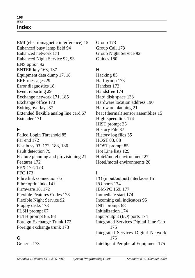
198 of 206
Index
206
d
EMI (electromagnetic interference) 15Enhanced busy lamp field 94Enhanced network 171Enhanced Night Service 92, 93ENS option 92ENTER key 163, 187Equipment data dump 17, 18ERR messages 29Error diagnostics 18Event reporting 29Exchange network 171, 185Exchange office 173Exiting overlays 37Extended flexible analog line card 67Extender 171
FFailed Login Threshold 85Far end 172Fast busy 93, 172, 183, 186Fault detection 79Feature planning and provisioning 21Features 172FEX 172, 173FFC 173Fibre link connections 61Fibre optic links 141Firmware 18, 172Flexible Features Codes 173Flexible Night Service 92Floppy disks 173FLSH prompt 67FLTH prompt 85, 88Foreign Exchange Trunk 172Foreign exchange trunk 173
GGeneric 173
Meridian 1 Options 51C, 61C, 81C System Progra
Group 173Group Call 173Group Night Service 92Guides 180
HHacking 85Half-group 173Handset 173Handsfree 174Hard disk space 133Hardware location address 190Hardware planning 21heat (thermal) sensor assemblies 15High-speed link 174HIST prompt 35History File 37History log files 35HOST 83, 88HOST prompt 85Hot Line lists 129Hotel/motel environment 27Hotel/motel environments 28
II/O (input/output) interfaces 15I/O ports 174IBM-PC 169, 177Immediate start 174Incoming call indicators 95INIT prompt 88Initialization 174Input/output (I/O) ports 174Integrated Services Digital Line Car
175Integrated Services Digital Network
175Intelligent Peripheral Equipment 175
mming Guide Standard 6.00 October 2000
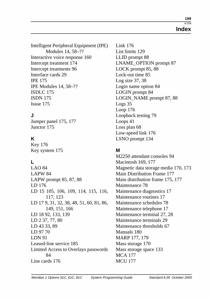
199of 206
Index
3
Intelligent Peripheral Equipment (IPEModules 14, 58–??
Interactive voice response 160Intercept treatment 174Intercept treatments 96Interface cards 29IPE 175IPE Modules 14, 58–??ISDLC 175ISDN 175Issue 175
JJumper panel 175, 177Junctor 175
KKey 176Key system 175
LLAO 84LAPW 84LAPW prompt 85, 87, 88LD 176LD 15 105, 106, 109, 114, 115, 116
117, 123LD 17 9, 31, 32, 38, 48, 51, 60, 81, 86
149, 151, 166LD 18 92, 133, 139LD 2 37, 77, 80LD 43 33, 89LD 97 70LDN 91Leased-line service 185Limited Access to Overlays password
84Line cards 176
Meridian 1 Options 51C, 61C, 81C System Progra
)
,
,
s
Link 176List limits 129LLID prompt 88LNAME_OPTION prompt 87LOCK prompt 85, 88Lock-out time 85Log size 37, 38Login name option 84LOGIN prompt 84LOGIN_NAME prompt 87, 88Logs 35Loop 176Loopback testing 79Loops 41Loss plan 68Low-speed link 176LSNO prompt 134
MM2250 attendant consoles 94Macintosh 169, 177Magnetic data storage media 170, 17Main Distribution Frame 177Main distribution frame 175, 177Maintenance 78Maintenance diagnostics 17Maintenance routines 17Maintenance schedules 78Maintenance telephone 17Maintenance terminal 27, 28Maintenance terminals 29Maintenance thresholds 67Manuals 180MARP 177, 179Mass storage 170Mass storage space 133MCA 177MCU 177
mming Guide Standard 6.00 October 2000
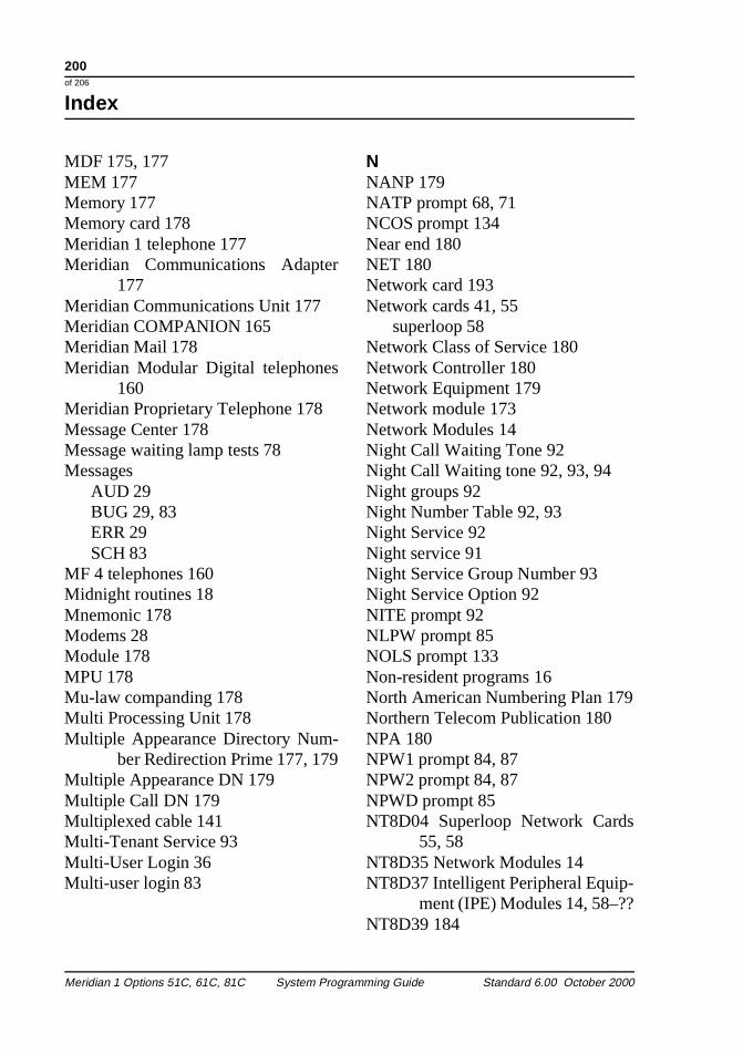
200 of 206
Index
206
9
MDF 175, 177MEM 177Memory 177Memory card 178Meridian 1 telephone 177Meridian Communications Adapte
177Meridian Communications Unit 177Meridian COMPANION 165Meridian Mail 178Meridian Modular Digital telephones
160Meridian Proprietary Telephone 178Message Center 178Message waiting lamp tests 78Messages
AUD 29BUG 29, 83ERR 29SCH 83
MF 4 telephones 160Midnight routines 18Mnemonic 178Modems 28Module 178MPU 178Mu-law companding 178Multi Processing Unit 178Multiple Appearance Directory Num-
ber Redirection Prime 177, 17Multiple Appearance DN 179Multiple Call DN 179Multiplexed cable 141Multi-Tenant Service 93Multi-User Login 36Multi-user login 83
Meridian 1 Options 51C, 61C, 81C System Progra
r
NNANP 179NATP prompt 68, 71NCOS prompt 134Near end 180NET 180Network card 193Network cards 41, 55
superloop 58Network Class of Service 180Network Controller 180Network Equipment 179Network module 173Network Modules 14Night Call Waiting Tone 92Night Call Waiting tone 92, 93, 94Night groups 92Night Number Table 92, 93Night Service 92Night service 91Night Service Group Number 93Night Service Option 92NITE prompt 92NLPW prompt 85NOLS prompt 133Non-resident programs 16North American Numbering Plan 179Northern Telecom Publication 180NPA 180NPW1 prompt 84, 87NPW2 prompt 84, 87NPWD prompt 85NT8D04 Superloop Network Cards
55, 58NT8D35 Network Modules 14NT8D37 Intelligent Peripheral Equip-
ment (IPE) Modules 14, 58–??NT8D39 184
mming Guide Standard 6.00 October 2000
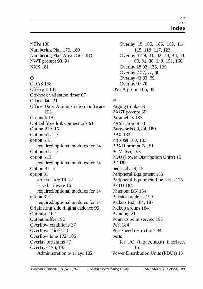
201of 206
Index
,
,
NTPs 180Numbering Plan 179, 180Numbering Plan Area Code 180NWT prompt 93, 94NXX 181
OODAS 168Off-hook 181Off-hook validation timer 67Office data 21Office Data Administration Software
168On-hook 182Optical fibre link connections 61Option 21A 15Option 51C 15option 51C
required/optional modules for 14Option 61C 15option 61E
required/optional modules for 14Option 81 15option 81
architecture 18–??base hardware 16required/optional modules for 14
option 81Crequired/optional modules for 14
Originating side ringing cadence 95Outpulse 182Output buffer 182Overflow conditions 37Overflow Tone 183Overflow tone 172, 186Overlay programs 77Overlays 176, 183
Administration overlays 182
Meridian 1 Options 51C, 61C, 81C System Progra
Overlay 15 105, 106, 109, 114115, 116, 117, 123
Overlay 17 9, 31, 32, 38, 48, 5160, 81, 86, 149, 151, 166
Overlay 18 92, 133, 139Overlay 2 37, 77, 80Overlay 43 33, 89Overlay 97 70
OVLA prompt 85, 88
PPaging trunks 69PAGT prompt 69Parameters 183PASS prompt 84Passwords 83, 84, 189PBX 183PBX set 160, 183PBXH prompt 78, 81PCM 165, 193PDU (Power Distribution Units) 15PE 183pedestals 14, 15Peripheral Equipment 183Peripheral Equipment line cards 175PFTU 184Phantom DN 184Physical address 190Pickup 162, 184, 187Pickup groups 184Planning 21Point-to-point service 185Port 184Port speed restrictions 84ports
for I/O (input/output) interfaces15
Power Distribution Units (PDUs) 15
mming Guide Standard 6.00 October 2000
202 of 206
Index
206
,
Power Fail Transfer Unit 184Power status 28PRI 184Primary Rate Interface 184Prime DN 185Print routines 17Printers 27, 35, 36printing
History File contents 35Privacy 131Private Branch Exchange 183Private line service 185Private network 185Processor 160Programmable read-only memory 18PROM 18Prompt 185Prompts
ADAN 31, 37, 38ALUL 69ALUS 69AUDT 88BKGD 78CONT 67COTL 68COTS 68CRCF 67CUST 85, 88, 105, 106, 109, 114
116, 117CY45 79, 81DIDS 68DNSZ 133, 134DROL 79, 81FLSH 67FLTH 85, 88HOST 85INIT 88LAPW 85, 87, 88
Meridian 1 Options 51C, 61C, 81C System Progra
,
LLID 88LNAME_OPTION 87LOCK 85, 88LOGIN 84LOGIN_NAME 87, 88LSNO 134NATP 68, 71NCOS 134NITE 92NLPW 85NOLS 133NPW1 84, 87NPW2 84, 87NPWD 85NWT 93, 94OVLA 85, 88PAGT 69PASS 84PBXH 78PWD2 87PWnn 85, 87RANR 69REQ 9, 31, 38, 48, 60, 70, 86, 87
123, 124, 133, 139SID 81SIZE 38, 133, 134SLOT 61STOR 134SUPL 60SUPT 61T2WN 69T2WT 69T2WV 69T4WN 69T4WT 69T4WV 69TBXH 81TDP 67
mming Guide Standard 6.00 October 2000
203of 206
Index
,
k
-
s
,
7
TEN 85TERM 60TID 67TN 139TNUM 68, 71TODR 79TOHY 67TRLL 79TTYP 68, 71TYPE 38, 48, 49, 50, 51, 60, 70, 81
86, 87, 105, 106, 109, 114115, 116, 117, 123, 133139
USER 28, 38WRT 134XMS 28XPE0 61XPE1 51, 61
Proprietary telephone 185PSTN 185Public Network Exchange code 181Public Switched Telephone Networ
185Pulse Code Modulation 165, 179, 193Pulse dialing 67PW1 84PWD1 83PWD2 84PWD2 prompt 87PWnn prompt 85, 87
QQPC414 Network Cards 41, 55QUA4 184QUA5 184QUA6 184Queuing 160, 161, 162, 185
Meridian 1 Options 51C, 61C, 81C System Progra
,,
RRAN 185RAN trunks 69RANR prompt 69Read Only Memory 172Receive levels 68Recorded Announcement 185Recorded announcement 96Recorded announcement trunks 69Recovery routines 18Redirection 161, 186Redundancy 186Regular telephone 186Release 186Remote access 28Remote peripheral equipment loop
back tests 79Remote peripheral equipment loop
42, 47Reorder Tone 186Reorder tone 172, 183REQ prompt 9, 31, 38, 48, 60, 70, 86
87, 123, 124, 133, 139Resident programs 16Response 186Response time-out 187Restriction 187RETURN key 163, 187Return key 187RFI (radio frequency interference) 15Ring Again 187Ringback tone 187Ringing number pickup 162, 184, 18ROM 172Rotary telephone 159RPE loopback tests 79RS232 176RS422 174
mming Guide Standard 6.00 October 2000
204 of 206
Index
206
RS423 174
SSaving data 37SBE card 171SCC 130SCH messages 83Schedules 18SCU 130SDI 187Secondary DN 187Secondary key 184Second-level administration passwor
84Security
lock-outs 85Security thresholds 85Segmented Bus Extender 171Serial Data Interface 187Service administration programs 17Service change 187Service change routines 17Service change terminal 28Service change terminals 29Service loop 188Set 188Set database 29Setting up a history file 38Setting up a traffic file 38SID 77SID prompt 81Signal companding 67Single Appearance DN 188Single Call DN 188Size 38SIZE prompt 38, 133, 134Slot number 188SLOT prompt 61
Meridian 1 Options 51C, 61C, 81C System Progra
d
Software 16audit 18customization 21data dump 18Non-resident 16printing 17resident 16service change 17traffic data accumulation 18
Software audit 17Software issues 175Software packaging 188Software release 192Software releases 173, 175spacer kits 15Special dial tone 188Special prefix code 188Special prefix codes 94Special services 160Speed Call Controllers 130Speed Call lists 128Speed Call Users 130SPRE 94, 173, 188SPRE codes 180SPWD 84SSC 129SSID command 77STAD command 80Standard Network 189Starting arrangement 189Station 189Station Control Password 189Status reporting 28STOR prompt 134Superloop 180Superloop network card 193Superloop Network Cards 58Superloop type 61
mming Guide Standard 6.00 October 2000
205of 206
Index
Superloops 170, 189Supervisory stations 85SUPL prompt 60SUPT prompt 61Switch-hook flash 176, 189Switchhook flash time 67SYSLOAD 190sysloads
History File contents and 35System clock 77System error reporting 28System events 35System faults 17System ID 77system messages
History File storage of 35System monitor 27, 28, 190, 193System Monitors 15System parameters 67System processor 160System Speed Call lists 129System terminal 17
TT2WN prompt 69T2WT prompt 69T2WV prompt 69T4WN prompt 69T4WT prompt 69T4WV prompt 69Tampering 83TDET 138TDP prompt 67TDS 190Telephone number 170TEN prompt 85Tenant to route restrictions 93TERM prompt 60
Meridian 1 Options 51C, 61C, 81C System Progra
Terminal 192Terminal emulation software 27Terminal Number 184, 190thermal sensor assemblies 15Thresholds 85TID prompt 67TIE trunk 190TIE trunk intercepts 97TIE trunks 69, 94Time slot 190Time stamp 77, 191Timeslot continuity faults 67TN 190TN prompt 139TNUM prompt 68, 71TODR prompt 79TOHY prompt 67Tone and Digit Switch 190Tone and digit switch loops 41Tone detectors 138top caps 14, 15Traffic 35, 191Traffic levels 29Traffic log 38Traffic log files 36Traffic monitoring 37Traffic parameters 37Traffic print program 18Traffic routines 17Traffic software 18Traffic studies 78Traffic terminal 28, 29Transfer Unit 184Transient data 21, 162, 182, 191Transmission path 164Transmission paths 176, 189, 190Transmit levels 68TRLL prompt 79
mming Guide Standard 6.00 October 2000
206 of 206
Index
206
2
4
Trunk Barring 93Trunk cards 176Trunk group 191Trunk group busy lamp field 95Trunk route access codes 180Trunk seizure 174Trunk signaling 138Trunk to Trunk Barring 94Trunk transmit and receive levels 68Trunks 191TSID command 77, 80TTAD command 80TTY 192TTY log files 36TTYP prompt 68, 71Twisted pair cable 141TYPE prompt 38, 48, 49, 50, 51, 60
70, 81, 86, 87, 105, 106, 109114, 115, 116, 117, 123, 133139
UU data 191UEM 178, 192UEMs (Universal Equipment Mod-
ules) 14Unity telephone 192Unity telephones 160Universal Equipment Module 178, 19User names 83USER prompt 28, 38USER0 83
VValue-added services 160Video data terminals 27Voice mail 160, 178
Meridian 1 Options 51C, 61C, 81C System Progra
,,,
WWarning Tone 94Warning Tone Class of Service 93, 9WATS 192Wide Area Telephone Service 192Wink start 192Worksheets 23WRT prompt 134WTA 93, 94WTD 93, 94
XX08 192X11 173, 192XMS prompt 28XNET 193XPE0 193XPE0 prompt 61XPE1 193XPE1 prompt 51, 61XPEC 193XSM 193
mming Guide Standard 6.00 October 2000
Family Product Manual Contacts Copyright FCC notice Trademarks Document number Product release Document release Date Publish
Meridian 1 Options 51C, 61C, 81C
System Programming Guide
© 1995–2000 Nortel Networks All Rights ReservedInformation is subject to change without notice. Nortel Networks reserves the right to make changes in design or components as progress in engineering and manufacturing may warrant. This equipment has been tested and found to comply with the limits for a Class A digital device pursuant to Part 15 of the FCC rules, and the radio interference regulations of Industry Canada. These limits are designed to provide reasonable protection against harmful interference when the equipment is operated in a commercial environment. This equipment generates, uses and can radiate radio frequency energy, and if not installed and used in accordance with the instruction manual, may cause harmful interference to radio communications. Operation of this equipment in a residential area is likely to cause harmful interference in which case the user will be required to correct the interference at their own expense.SL-1, Meridian 1 and Digitone are trademarks of Nortel Networks. Intel and Pentium are trademarks of Intel. Corporation. cPCI is a trademark of PCI Industrial Computer Manufacturers Group. IBDN and BIX are trademarks of NORDX/CDT Inc.
PO Number: P0912433Document release: Standard 6.00Date: October 2000Printed in Canada