Embed Size (px)
Citation preview
Digital Production Environment
QUICK START GUIDE
CAUTION: TO REDUCE THE RISK OF ELECTRIC SHOCK, DO NOTREMOVE COVER (OR BACK). NO USER-SERVICEABLE PARTSINSIDE. REFER SERVICING TO QUALIFIED SERVICE PERSONNEL.
The exclamation point within an equilateral triangle is intended to alert the user to the pres-ence of important operating and maintenance (servicing) instructions in the literatureaccompanying the appliance.
The lightning flash with arrowhead symbol, within an equilateral triangle, is intended to alertthe user to the presence of uninsulated “dangerous voltage” within the product’s enclosurethat may be of sufficient magnitude to constitute a risk of electric shock to persons.
This appliance has a serial numberlocated on the rear panel. Please recordthe model number and serial numberand retain them for your records.Model numberSerial number
WARNING: TO PREVENT FIRE OR SHOCKHAZARD, DO NOT EXPOSE THIS
APPLIANCE TO RAIN OR MOISTURE.
9101448000
2 TASCAM SX-1 Quick Start Guide
Important Safety Precautions
IMPORTANT (for U.K. Customers)DO NOT cut off the mains plug from this equipment.If the plug fitted is not suitable for the power points in your home orthe cable is too short to reach a power point, then obtain anappropriate safety approved extension lead or consult your dealer.
If nonetheless the mains plug is cut off, remove the fuse and disposeof the plug immediately, to avoid a possible shock hazard byinadvertent connection to the mains supply.
If this product is not provided with a mains plug, or one has to befitted, then follow the instructions given below:
IMPORTANT: The wires in this mains lead are coloured inaccordance with the following code:
GREEN-AND-YELLOW : EARTHBLUE : NEUTRALBROWN : LIVE
WARNING: This apparatus must be earthed.As the colours of the wires in the mains lead of this apparatus maynot correspond with the coloured markings identifying the terminalsin your plug proceed as follows:
The wire which is coloured GREEN-and-YELLOW must beconnected to the terminal in the plug which is marked by the letterE or by the safety earth symbol ç or coloured GREEN or GREEN-and-YELLOW.
The wire which is coloured BLUE must be connected to the terminalwhich is marked with the letter N or coloured BLACK.
The wire which is coloured BROWN must be connected to theterminal which is marked with the letter L or coloured RED.
When replacing the fuse only a correctly rated approved type shouldbe used and be sure to re-fit the fuse cover.
IF IN DOUBT — CONSULT A COMPETENT ELECTRICIAN.
TO THE USER
This equipment has been tested and found tocomply with the limits for a Class A digital device,pursuant to Part 15 of the FCC Rules. Theselimits are designed to provide reasonableprotection against harmful interference when theequipment is operated in a commercialenvironment. This equipment generates, uses,and can radiate radio frequency energy and, ifnot installed and used in accordance with theinstruction manual, may cause harmfulinterference to radio communications.Operation of this equipment in a residental areais likely to cause harmful interference in whichcase the user will be required to correct theinterference at his own expense.
CAUTIONChanges or modifications to this equipment notexpressly approved by TEAC CORPORATIONfor compliance could void the user’s authority tooperate this equipment.
For the consumers in Europe
WARNINGThis is a Class A product. In a domestic environment, thisproduct may cause radio interference in which case the usermay be required to take adequate measures.
Pour les utilisateurs en Europe
AVERTISSEMENTIl s’agit d’un produit de Classe A. Dans un environnementdomestique, cet appareil peut provoquer des interférencesradio, dans ce cas l’utilisateur peut être amené à prendredes mesures appropriées.
Für Kunden in Europa
WarnungDies is eine Einrichtung, welche die Funk-Entstörung nachKlasse A besitzt. Diese Einrichtung kann im WohnbereichFunkstörungen versursachen ; in diesem Fall kann vomBetrieber verlang werden, angemessene Maßnahmendurchzuführen und dafür aufzukommen.
For U.S.A
The equipment draws nominal non-operating power from theAC outlet with its POWER switch in the off position.
I
CAUTION:MPORTANT SAFETY INSTRUCTIONS…Read all of these Instructions.…Save these Instructions for later use.…Follow all Warnings and Instructions marked on the audio
equipment.
1) Read Instructions — All the safety and operating instructionsshould be read before the product is operated.2) Retain Instructions — The safety and operating instructionsshould be retained for future reference.3) Heed Warnings — All warnings on the product and in the operatinginstructions should be adhered to.4) Follow Instructions — All operating and use instructions should befollowed.5) Cleaning — Unplug this product from the wall outlet before clean-ing. Do not use liquid cleaners or aerosol cleaners. Use a damp cloth forcleaning.6) Attachments — Do not use attachments not recommended by theproduct manufacturer as they may cause hazards.7) Water and Moisture — Do not use this product near water — forexample, near a bath tub, wash bowl, kitchen sink, or laundry tub; in awet basement; or near a swimming pool; and the like.8) Accessories — Do not place this product on an unstable cart, stand,tripod, bracket, or table. The product may fall, causing serious injury to achild or adult, and serious damage to the product. Use only with a cart,stand, tripod, bracket, or table recommended by the manufacturer, or soldwith the product. Any mounting of the product should follow the manu-facturer’s instructions, and should use a mounting accessory recom-mended by the manufacturer.9) A product and cart combination should be moved with care. Quickstops, excessive force, and uneven surfaces may cause the product andcart combination to overturn.
10) Ventilation — Slots and openings in the cabinet are provided forventilation and to ensure reliable operation of the product and to protectit from overheating, and these openings must not be blocked or covered.The openings should never be blocked by placing the product on a bed,sofa, rug, or other similar surface. This product should not be placed in abuilt-in installation such as a bookcase or rack unless proper ventilationis provided or the manufacturer’s instructions have been adhered to.11) Power Sources — This product should be operated only from thetype of power source indicated on the marking label. If you are not sureof the type of power supply to your home, consult your product dealer orlocal power company. For products intended to operate from batterypower, or other sources, refer to the operating instructions.12) Grounding or Polarization — This product may be equippedwith a polarized alternating-current line plug (a plug having one bladewider than the other). This plug will fit into the power outlet only oneway. This is a safety feature. If you are unable to insert the plug fully intothe outlet, try reversing the plug. If the plug should still fail to fit, contactyour electrician to replace your obsolete outlet. Do not defeat the safetypurpose of the polarized plug.13) Power-Cord Protection — Power-supply cords should be routedso that they are not likely to be walked on or pinched by items placedupon or against them, paying particular attention to cords at plugs, con-venience receptacles, and the point where they exit from the product.14) Outdoor Antenna Grounding — If an outside antenna or cablesystem is connected to the product, be sure the antenna or cable system isgrounded so as to provide some protection against voltage surges andbuilt-up static charges. Article 810 of the National Electrical Code,ANSI/NFPA 70, provides information with regard to proper groundingof the mast and supporting structure, grounding of the lead-in wire to anantenna discharge unit, size of grounding conductors, location ofantenna-discharge unit, connection to grounding electrodes, and require-ments for the grounding electrode.
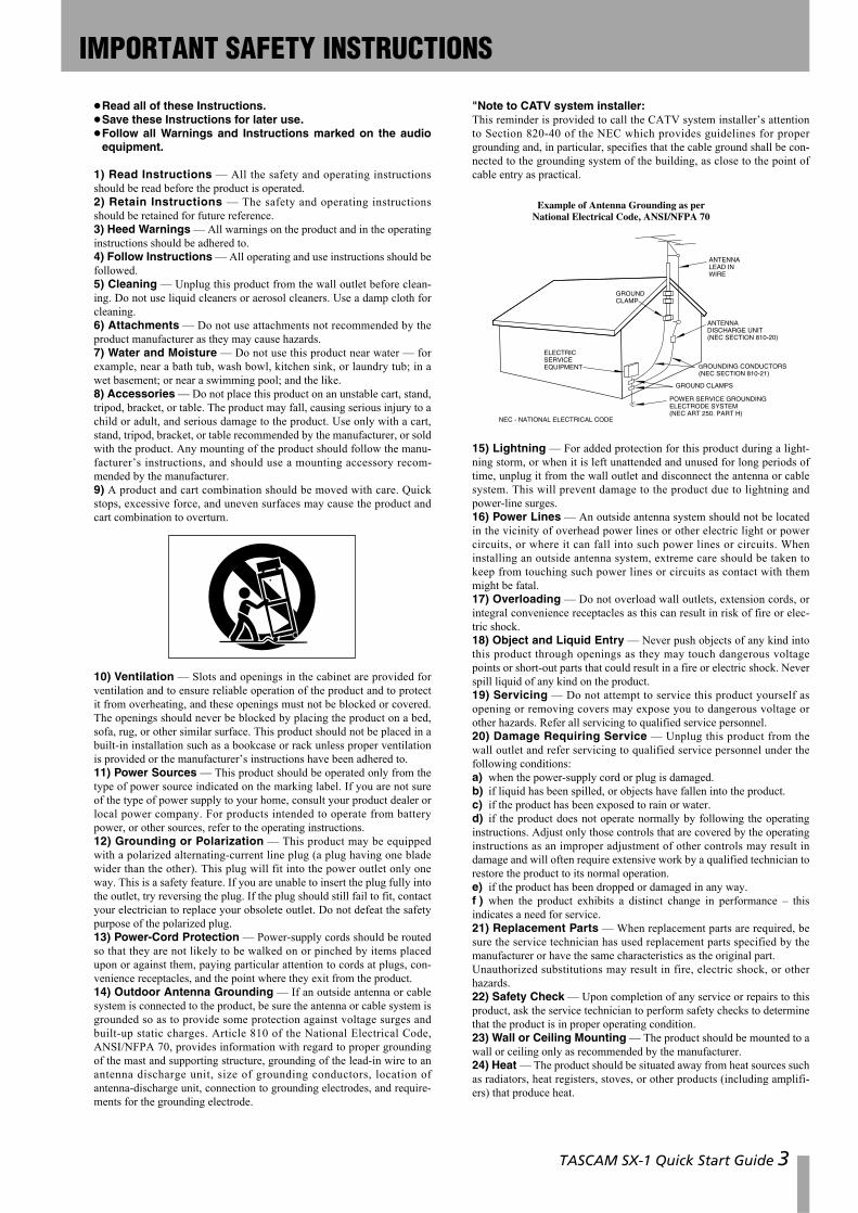
"Note to CATV system installer:This reminder is provided to call the CATV system installer’s attentionto Section 820-40 of the NEC which provides guidelines for propergrounding and, in particular, specifies that the cable ground shall be con-nected to the grounding system of the building, as close to the point ofcable entry as practical.
15) Lightning — For added protection for this product during a light-ning storm, or when it is left unattended and unused for long periods oftime, unplug it from the wall outlet and disconnect the antenna or cablesystem. This will prevent damage to the product due to lightning andpower-line surges.16) Power Lines — An outside antenna system should not be locatedin the vicinity of overhead power lines or other electric light or powercircuits, or where it can fall into such power lines or circuits. Wheninstalling an outside antenna system, extreme care should be taken tokeep from touching such power lines or circuits as contact with themmight be fatal.17) Overloading — Do not overload wall outlets, extension cords, orintegral convenience receptacles as this can result in risk of fire or elec-tric shock.18) Object and Liquid Entry — Never push objects of any kind intothis product through openings as they may touch dangerous voltagepoints or short-out parts that could result in a fire or electric shock. Neverspill liquid of any kind on the product.19) Servicing — Do not attempt to service this product yourself asopening or removing covers may expose you to dangerous voltage orother hazards. Refer all servicing to qualified service personnel.20) Damage Requiring Service — Unplug this product from thewall outlet and refer servicing to qualified service personnel under thefollowing conditions:a) when the power-supply cord or plug is damaged.b) if liquid has been spilled, or objects have fallen into the product.c) if the product has been exposed to rain or water.d) if the product does not operate normally by following the operatinginstructions. Adjust only those controls that are covered by the operatinginstructions as an improper adjustment of other controls may result indamage and will often require extensive work by a qualified technician torestore the product to its normal operation.e) if the product has been dropped or damaged in any way.f ) when the product exhibits a distinct change in performance – thisindicates a need for service.21) Replacement Parts — When replacement parts are required, besure the service technician has used replacement parts specified by themanufacturer or have the same characteristics as the original part. Unauthorized substitutions may result in fire, electric shock, or otherhazards.22) Safety Check — Upon completion of any service or repairs to thisproduct, ask the service technician to perform safety checks to determinethat the product is in proper operating condition.23) Wall or Ceiling Mounting — The product should be mounted to awall or ceiling only as recommended by the manufacturer.24) Heat — The product should be situated away from heat sources suchas radiators, heat registers, stoves, or other products (including amplifi-ers) that produce heat.
ANTENNALEAD INWIRE
ANTENNADISCHARGE UNIT(NEC SECTION 810-20)
GROUNDING CONDUCTORS(NEC SECTION 810-21)
GROUND CLAMPS
POWER SERVICE GROUNDINGELECTRODE SYSTEM(NEC ART 250. PART H)
NEC - NATIONAL ELECTRICAL CODE
ELECTRICSERVICEEQUIPMENT
Example of Antenna Grounding as perNational Electrical Code, ANSI/NFPA 70
GROUNDCLAMP
TASCAM SX-1 Quick Start Guide 3
SAFETY INFORMATION
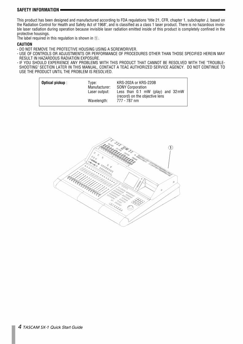
This product has been designed and manufactured according to FDA regulations "title 21, CFR, chapter 1, subchapter J, based onthe Radiation Control for Health and Safety Act of 1968", and is classified as a class 1 laser product. There is no hazardous invisi-ble laser radiation during operation because invisible laser radiation emitted inside of this product is completely confined in theprotective housings.The label required in this regulation is shown in 1.CAUTION- DO NOT REMOVE THE PROTECTIVE HOUSING USING A SCREWDRIVER.- USE OF CONTROLS OR ADJUSTMENTS OR PERFORMANCE OF PROCEDURES OTHER THAN THOSE SPECIFIED HEREIN MAY
RESULT IN HAZARDOUS RADIATION EXPOSURE.- IF YOU SHOULD EXPERIENCE ANY PROBLEMS WITH THIS PRODUCT THAT CANNOT BE RESOLVED WITH THE "TROUBLE-
SHOOTING" SECTION LATER IN THIS MANUAL, CONTACT A TEAC AUTHORIZED SERVICE AGENCY. DO NOT CONTINUE TOUSE THE PRODUCT UNTIL THE PROBLEM IS RESOLVED.
Optical pickup : Type: KRS-202A or KRS-220BManufacturer: SONY CorporationLaser output: Less than 0.1 mW (play) and 32mW
(record) on the objective lensWavelength: 777 - 787 nm
1
4 TASCAM SX-1 Quick Start Guide
Table of Contents
TASCAM SX-1 Quick Start Guide 5
Chapter 1 – IntroductionSX-1 Standard Features ..................................6Unpacking .......................................................7Box Contents...................................................7Registration.....................................................7Options ............................................................7Support and Updates .....................................7
Using These Manuals ................................. 8Quick Start Guide............................................8Owner's Manual .............................................8Using the Internet...........................................8Documentation Conventions .........................8
Hot Tips .......................................................8Operating Conventions.............................. 9
Multi-Function Keys........................................9Virtual Channel Pots .......................................9VGA Screen Navigation ..................................9LCD Screen Navigation ...................................10LCD or VGA......................................................10Fader Banks .....................................................11
Chapter 2 – Getting StartedSpeaker Placement .........................................13VGA Monitor Placement.................................13Mouse and Keyboard .....................................13Plugging Into Power.......................................13
Don't Interrupt! ..........................................13“Safe” startup .............................................13Shutting down your SX-1 ..........................14Being Grounded ..........................................14Avoiding Ground Loops .............................14
Chapter 3 – Making ConnectionsGetting Sound ............................................ 15
Phones .............................................................15Studio ..............................................................15Control Room..................................................15Master Stereo Outs.........................................16
Basic Wiring Diagram................................. 16Important Rear Connections...................... 17Loading the Demo Song ............................ 18
Loading the Audio Demo Song .....................18
Chapter 4 – MIDI BasicsConnecting MIDI......................................... 20Loading the MIDI Song Demo ................... 21
MIDI Instrument Track Assignment...............21MIDI Instrument Track Assignment...............21
Chapter 5 – Essential MovesBack Up and Shutdown ............................. 23
Backing Up ......................................................23From the VGA screen......................................23From the LCD screen.......................................24
Shutdown Procedure ................................. 24
Chapter 6 – Taking ControlAudio Monitoring........................................... 26Information Display ....................................... 26Mix Control ..................................................... 26Settings Management.................................... 26MIDI ................................................................. 27Editing ............................................................. 27Transport and Data Entry .............................. 27
Chapter 7 – Basic MovesGetting Around ...........................................28A Quick Explanation of a Few Important
Terms ........................................................28Slot .............................................................. 28Take ............................................................. 28Clip .............................................................. 28Channel ....................................................... 28Mutes and Solos ......................................... 29
Creating a New Project...............................29On the VGA..................................................... 29On the LCD...................................................... 30
To Record an Audio Track ..........................30On the VGA..................................................... 30On the LCD...................................................... 31
Recording MIDI............................................32On the VGA..................................................... 32On the LCD...................................................... 32
Using Locate Points and Autopunch .........33A word about the CAPTURE key ............... 33
Setting a locate point..................................... 33Recalling a Locate Point ................................. 33
Using Autopunch ........................................33Updating the SX-1 software ......................34
Chapter 8 – A quick look at a few shortcuts
Make a quick headphone mix....................35Make 5 different mixes for different players
quickly.......................................................35Quickly move all of your faders (on the current
layer) back to unity..................................35Quickly make a Fader Group......................35Quickly Solo-Safe a channel (or channels) 35Quickly link a pair of channels on the
console......................................................36Quickly mixdown a number of sources to a
stereo pair ................................................36Quickly use the LCD and the VGA screens to
show separate things ..............................36Track a drum kit, even though you have no
free mixer channels .................................36Quickly select every MIDI note on a MIDI
Take...........................................................37Quickly name a number of similar types of
things ........................................................37
Chapter 1 – Introduction
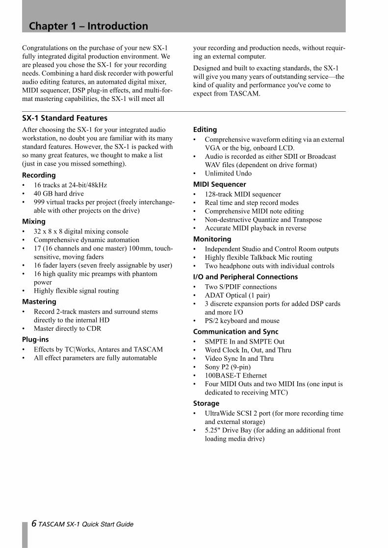
Congratulations on the purchase of your new SX-1 fully integrated digital production environment. We are pleased you chose the SX-1 for your recording needs. Combining a hard disk recorder with powerful audio editing features, an automated digital mixer, MIDI sequencer, DSP plug-in effects, and multi-for-mat mastering capabilities, the SX-1 will meet all
your recording and production needs, without requir-ing an external computer.Designed and built to exacting standards, the SX-1 will give you many years of outstanding service—the kind of quality and performance you've come to expect from TASCAM.
SX-1 Standard FeaturesAfter choosing the SX-1 for your integrated audio workstation, no doubt you are familiar with its many standard features. However, the SX-1 is packed with so many great features, we thought to make a list (just in case you missed something).Recording• 16 tracks at 24-bit/48kHz• 40 GB hard drive• 999 virtual tracks per project (freely interchange-
able with other projects on the drive)Mixing• 32 x 8 x 8 digital mixing console• Comprehensive dynamic automation• 17 (16 channels and one master) 100mm, touch-
sensitive, moving faders• 16 fader layers (seven freely assignable by user)• 16 high quality mic preamps with phantom
power• Highly flexible signal routingMastering• Record 2-track masters and surround stems
directly to the internal HD• Master directly to CDRPlug-ins• Effects by TC|Works, Antares and TASCAM• All effect parameters are fully automatable
Editing• Comprehensive waveform editing via an external
VGA or the big, onboard LCD.• Audio is recorded as either SDII or Broadcast
WAV files (dependent on drive format)• Unlimited UndoMIDI Sequencer• 128-track MIDI sequencer• Real time and step record modes• Comprehensive MIDI note editing• Non-destructive Quantize and Transpose• Accurate MIDI playback in reverseMonitoring• Independent Studio and Control Room outputs• Highly flexible Talkback Mic routing• Two headphone outs with individual controlsI/O and Peripheral Connections• Two S/PDIF connections• ADAT Optical (1 pair)• 3 discrete expansion ports for added DSP cards
and more I/O• PS/2 keyboard and mouseCommunication and Sync• SMPTE In and SMPTE Out• Word Clock In, Out, and Thru• Video Sync In and Thru• Sony P2 (9-pin)• 100BASE-T Ethernet• Four MIDI Outs and two MIDI Ins (one input is
dedicated to receiving MTC)Storage• UltraWide SCSI 2 port (for more recording time
and external storage)• 5.25" Drive Bay (for adding an additional front
loading media drive)
6 TASCAM SX-1 Quick Start Guide
Chapter 1 –Introduction
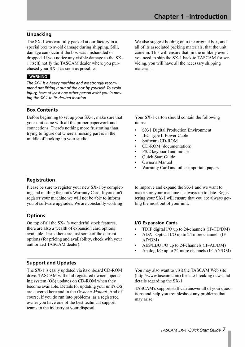
UnpackingThe SX-1 was carefully packed at our factory in a special box to avoid damage during shipping. Still, damage can occur if the box was mishandled or dropped. If you notice any visible damage to the SX-1 itself, notify the TASCAM dealer where you pur-chased your SX-1 as soon as possible.
WARNING
The SX-1 is a heavy machine and we strongly recom-mend not lifting it out of the box by yourself. To avoid injury, have at least one other person assist you in mov-ing the SX-1 to its desired location.
We also suggest holding onto the original box, and all of its associated packing materials, that the unit came in. This will ensure that, in the unlikely event you need to ship the SX-1 back to TASCAM for ser-vicing, you will have all the necessary shipping materials.
Box ContentsBefore beginning to set up your SX-1, make sure that your unit came with all the proper paperwork and connections. There's nothing more frustrating than trying to figure out where a missing part is in the middle of hooking up your studio.
Your SX-1 carton should contain the following items:• SX-1 Digital Production Environment• IEC Type II Power Cable• Software CD-ROM• CD-ROM (documentation)• PS/2 keyboard and mouse• Quick Start Guide• Owner's Manual• Warranty Card and other important papers
RegistrationPlease be sure to register your new SX-1 by complet-ing and mailing the unit's Warranty Card. If you don't register your machine we will not be able to inform you of software upgrades. We are constantly working
to improve and expand the SX-1 and we want to make sure your machine is always up to date. Regis-tering your SX-1 will ensure that you are always get-ting the most out of your unit.
OptionsOn top of all the SX-1's wonderful stock features, there are also a wealth of expansion card options available. Listed here are just some of the current options (for pricing and availability, check with your authorized TASCAM dealer).
I/O Expansion Cards• TDIF digital I/O up to 24-channels (IF-TD/DM)• ADAT Optical I/O up to 24 more channels (IF-
AD/DM)• AES/EBU I/O up to 24-channels (IF-AE/DM)• Analog I/O up to 24 more channels (IF-AN/DM)
Support and UpdatesThe SX-1 is easily updated via its onboard CD-ROM drive. TASCAM will mail registered owners operat-ing system (OS) updates on CD-ROM when they become available. Details for updating your unit's OS are covered here and in the Owner's Manual. And of course, if you do run into problems, as a registered owner you have one of the best technical support teams in the industry at your disposal.
You may also want to visit the TASCAM Web site (http://www.tascam.com) for late-breaking news and details regarding the SX-1.TASCAM's support staff can answer all of your ques-tions and help you troubleshoot any problems that may arise.
TASCAM SX-1 Quick Start Guide 7
Chapter 1 –Introduction
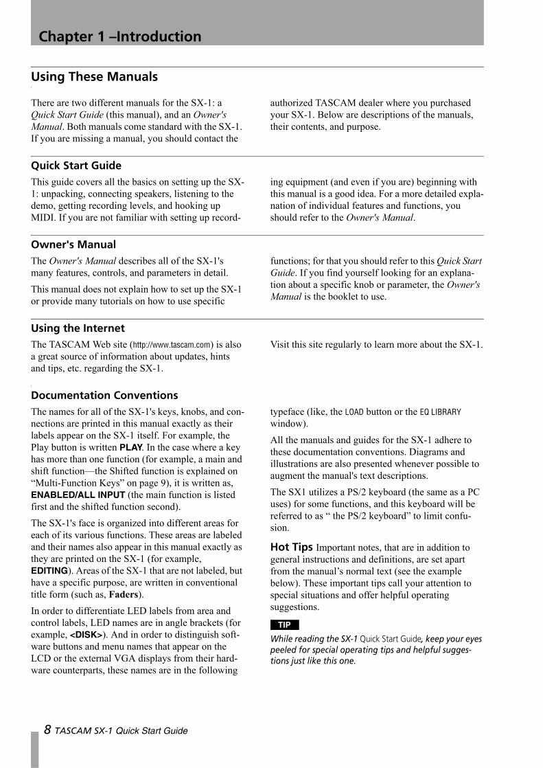
Using These Manuals
There are two different manuals for the SX-1: a Quick Start Guide (this manual), and an Owner's Manual. Both manuals come standard with the SX-1. If you are missing a manual, you should contact the
authorized TASCAM dealer where you purchased your SX-1. Below are descriptions of the manuals, their contents, and purpose.
Quick Start GuideThis guide covers all the basics on setting up the SX-1: unpacking, connecting speakers, listening to the demo, getting recording levels, and hooking up MIDI. If you are not familiar with setting up record-
ing equipment (and even if you are) beginning with this manual is a good idea. For a more detailed expla-nation of individual features and functions, you should refer to the Owner's Manual.
Owner's ManualThe Owner's Manual describes all of the SX-1's many features, controls, and parameters in detail.This manual does not explain how to set up the SX-1 or provide many tutorials on how to use specific
functions; for that you should refer to this Quick Start Guide. If you find yourself looking for an explana-tion about a specific knob or parameter, the Owner's Manual is the booklet to use.
Using the InternetThe TASCAM Web site (http://www.tascam.com) is also a great source of information about updates, hints and tips, etc. regarding the SX-1.
Visit this site regularly to learn more about the SX-1.
Documentation ConventionsThe names for all of the SX-1's keys, knobs, and con-nections are printed in this manual exactly as their labels appear on the SX-1 itself. For example, the Play button is written PLAY. In the case where a key has more than one function (for example, a main and shift function—the Shifted function is explained on “Multi-Function Keys” on page 9), it is written as, ENABLED/ALL INPUT (the main function is listed first and the shifted function second).The SX-1's face is organized into different areas for each of its various functions. These areas are labeled and their names also appear in this manual exactly as they are printed on the SX-1 (for example, EDITING). Areas of the SX-1 that are not labeled, but have a specific purpose, are written in conventional title form (such as, Faders).In order to differentiate LED labels from area and control labels, LED names are in angle brackets (for example, <DISK>). And in order to distinguish soft-ware buttons and menu names that appear on the LCD or the external VGA displays from their hard-ware counterparts, these names are in the following
typeface (like, the LOAD button or the EQ LIBRARY window).All the manuals and guides for the SX-1 adhere to these documentation conventions. Diagrams and illustrations are also presented whenever possible to augment the manual's text descriptions.The SX1 utilizes a PS/2 keyboard (the same as a PC uses) for some functions, and this keyboard will be referred to as “ the PS/2 keyboard” to limit confu-sion.
Hot Tips Important notes, that are in addition to general instructions and definitions, are set apart from the manual’s normal text (see the example below). These important tips call your attention to special situations and offer helpful operating suggestions.
TIP
While reading the SX-1 Quick Start Guide, keep your eyes peeled for special operating tips and helpful sugges-tions just like this one.
8 TASCAM SX-1 Quick Start Guide
Chapter 1 –Introduction
Operating Conventions
Multi-Function KeysSome keys have multiple functions. A key’s primary function is accessed by simply pressing the key. Sec-ondary functions are accessed by entering Shift mode. Press the SHIFT key on the Numeric Keypad,
and then press the multi-function key to reach its sec-ondary function. Think of the SHIFT key just like the shift key of a standard PS/2 keyboard—it serves a similar purpose.
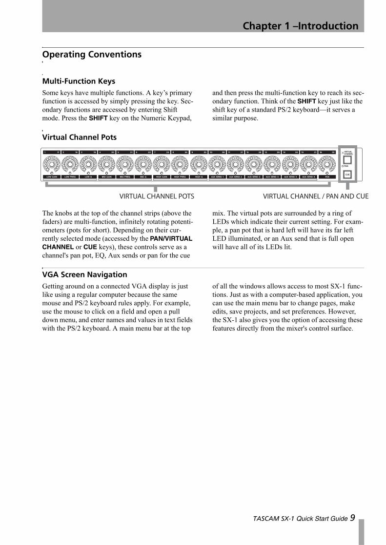
Virtual Channel Pots
The knobs at the top of the channel strips (above the faders) are multi-function, infinitely rotating potenti-ometers (pots for short). Depending on their cur-rently selected mode (accessed by the PAN/VIRTUAL CHANNEL or CUE keys), these controls serve as a channel's pan pot, EQ, Aux sends or pan for the cue
mix. The virtual pots are surrounded by a ring of LEDs which indicate their current setting. For exam-ple, a pan pot that is hard left will have its far left LED illuminated, or an Aux send that is full open will have all of its LEDs lit.
VGA Screen NavigationGetting around on a connected VGA display is just like using a regular computer because the same mouse and PS/2 keyboard rules apply. For example, use the mouse to click on a field and open a pull down menu, and enter names and values in text fields with the PS/2 keyboard. A main menu bar at the top
of all the windows allows access to most SX-1 func-tions. Just as with a computer-based application, you can use the main menu bar to change pages, make edits, save projects, and set preferences. However, the SX-1 also gives you the option of accessing these features directly from the mixer's control surface.
TASCAM SX-1 Quick Start Guide 9
Chapter 1 –Introduction
LCD Screen Navigation
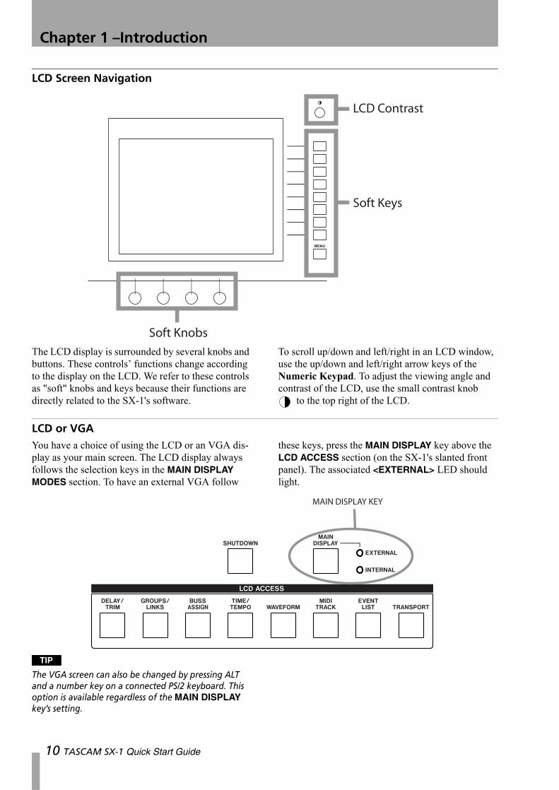
The LCD display is surrounded by several knobs and buttons. These controls’ functions change according to the display on the LCD. We refer to these controls as "soft" knobs and keys because their functions are directly related to the SX-1's software.
To scroll up/down and left/right in an LCD window, use the up/down and left/right arrow keys of the Numeric Keypad. To adjust the viewing angle and contrast of the LCD, use the small contrast knob
to the top right of the LCD.
LCD or VGAYou have a choice of using the LCD or an VGA dis-play as your main screen. The LCD display always follows the selection keys in the MAIN DISPLAY MODES section. To have an external VGA follow
these keys, press the MAIN DISPLAY key above the LCD ACCESS section (on the SX-1's slanted front panel). The associated <EXTERNAL> LED should light.
TIP
The VGA screen can also be changed by pressing ALT and a number key on a connected PS/2 keyboard. This option is available regardless of the MAIN DISPLAY key’s setting.
10 TASCAM SX-1 Quick Start Guide
Chapter 1 –Introduction
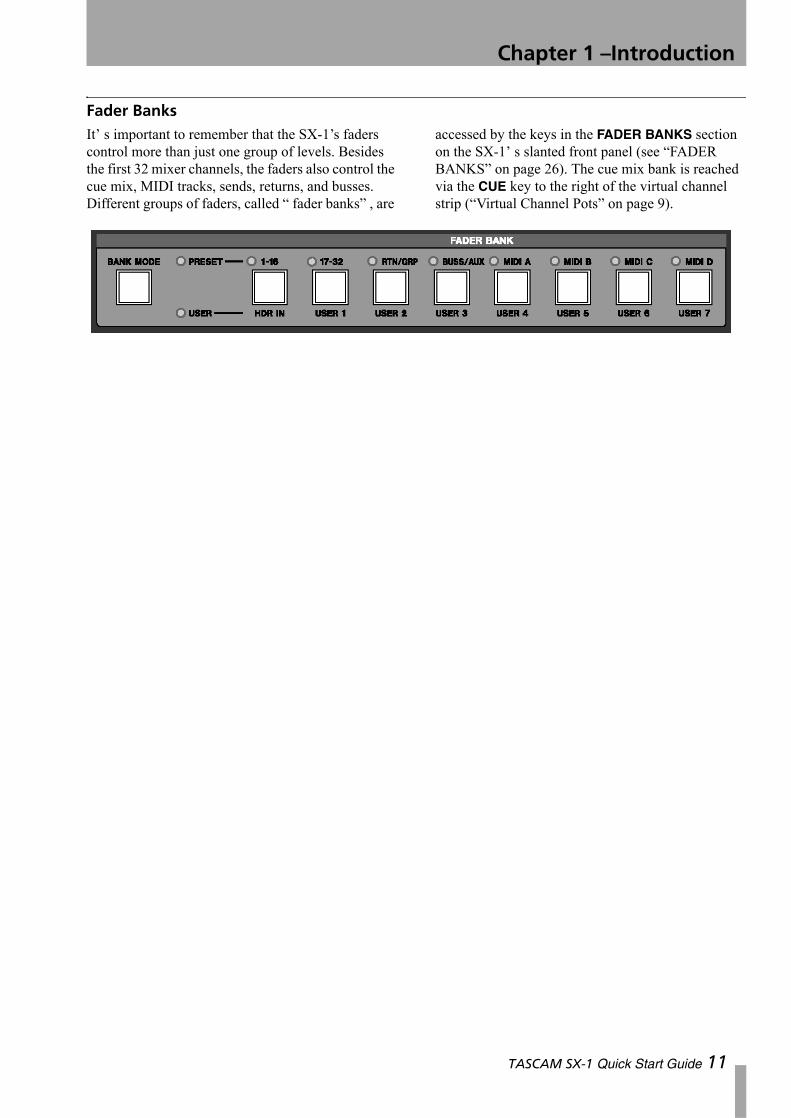
Fader BanksIt’ s important to remember that the SX-1’s faders control more than just one group of levels. Besides the first 32 mixer channels, the faders also control the cue mix, MIDI tracks, sends, returns, and busses. Different groups of faders, called “ fader banks” , are
accessed by the keys in the FADER BANKS section on the SX-1’ s slanted front panel (see “FADER BANKS” on page 26). The cue mix bank is reached via the CUE key to the right of the virtual channel strip (“Virtual Channel Pots” on page 9).
TASCAM SX-1 Quick Start Guide 11
Chapter 2 – Getting Started
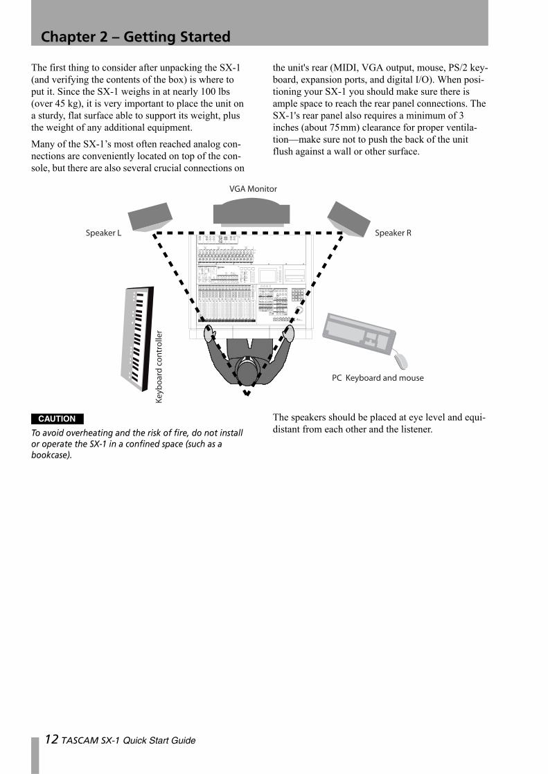
The first thing to consider after unpacking the SX-1 (and verifying the contents of the box) is where to put it. Since the SX-1 weighs in at nearly 100 lbs (over 45 kg), it is very important to place the unit on a sturdy, flat surface able to support its weight, plus the weight of any additional equipment.Many of the SX-1’s most often reached analog con-nections are conveniently located on top of the con-sole, but there are also several crucial connections on
the unit's rear (MIDI, VGA output, mouse, PS/2 key-board, expansion ports, and digital I/O). When posi-tioning your SX-1 you should make sure there is ample space to reach the rear panel connections. The SX-1's rear panel also requires a minimum of 3 inches (about 75mm) clearance for proper ventila-tion—make sure not to push the back of the unit flush against a wall or other surface.
CAUTION
To avoid overheating and the risk of fire, do not install or operate the SX-1 in a confined space (such as a bookcase).
The speakers should be placed at eye level and equi-distant from each other and the listener.
12 TASCAM SX-1 Quick Start Guide
Chapter 2 –Getting Started
Speaker PlacementWe recommend against putting your speakers on top of the SX-1. Though it looks like there might be space for speakers on the console's top, putting speakers here can obstruct heat dispersion, and improperly shielded speakers may damage the machine's hard drives—remember, the SX-1 is a computer. Instead, we suggest putting your speakers on their own individual speaker stands, making sure
to position your speakers correctly for proper moni-toring (see the illustration above).
TIP
If you plan on positioning your speakers within 3 feet (1 m) of your VGA display and your hard drive (remem-ber, there's a hard drive in the SX-1), we recommend using shielded monitors. This will protect your display and hard drive data from damage caused by the mag-netic fields of unshielded speakers.
VGA Monitor PlacementWhile you do not have to use a VGA display with the SX-1 (it is possible to perform most operations on the SX-1 via its onboard LCD screen), the full power of the unit is only truly realized by adding an external display. We recommend a 15-inch or larger screen (the VGA output resolution of the SX-1 is preset to 1024 by 768 pixels).
As well, though there appears to be space on top of the SX-1 for setting a VGA display, we do not rec-ommend this. Placing a VGA display (especially a large screen unit) on the top panel can cause ventila-tion and magnetic problems and may damage the SX-1's finish. However, a lightweight, flat-screen display can sit comfortably atop the SX-1.
Mouse and KeyboardThere are dedicated knobs and keys surrounding the LCD screen for navigating windows and pages (“LCD Screen Navigation” on page 10). These con-trols make it possible to get around the LCD screen without a mouse and PS/2 keyboard. However, the provided mouse and keyboard are required for navi-
gating an external VGA display (the mouse and key-board ports are found on the unit's rear—“Important Rear Connections” on page 17. When using an exter-nal display, make sure to have enough space near by your SX-1 to set the keyboard and mouse.
Plugging Into PowerThe process of recording, storing, and reading back digital audio data from a hard drive is a complex task that is very sensitive to changes in your AC line’s current. These line irregularities can interrupt data transmission and cause file write errors - which can lead to audio signal degradation and dropouts. To avoid such pitfalls, we suggest keeping your SX-1 plugged into a power regulator. Power regulators work to keep the incoming AC power at a constant 120 VAC (or whatever you use for your local volt-age), and this will help keep your machine healthy and running smoothly. You may also consider the use of a surge protector and/or a UPS (uninterruptible power supply). Make sure that all such items have power and voltage ratings compatible with the SX-1.
Don't Interrupt! Consider buying an Uninter-ruptable Power Supply (UPS) for your SX-1. This is not a prerequisite, but it can be a real life saver—or should we say, data saver. Even though your SX-1
autosaves regularly, a loss of power while saving could possibly result in data loss.However, with your SX-1 plugged into a UPS, you can avoid this hazard. A good UPS will provide enough power to run your SX-1 for several minutes, without power from a utility company. This extra power gives you time to complete your current action and perform a proper shutdown, ensuring that data is not lost.
“Safe” startup On rare occasions, the SX-1 may not be able to load the last project you worked on when it starts up (disk problems, etc.). If this happens to you:
1 Turn on the SX-1 as usual, but before the screen shows the “ghost” TASCAM and SX-1 logos, press and hold the PANIC key for a few seconds.
2 The SX-1 now boots, but does not automati-cally load the last project.
TASCAM SX-1 Quick Start Guide 13
Chapter 2 –Getting Started
3 You can now restore the offending project from a backup, or take whatever steps are necessary to restore the integrity of your data.
Shutting down your SX-1 Proper shutdown and regular backup of your SX-1 is extremely impor-tant. Failure to shutdown your SX-1 correctly before powering off can increase the possibility of corrupted data in your saved files. Without regular backup, the possibility that an unforeseen problem could wipe out some, or all, of your data increases drastically. When it comes to your hard work, don't take any chances; always perform a proper shutdown and backup of your projects after each session. See “Shutdown Procedure” on page 24.
Being Grounded Never plug your SX-1 into an ungrounded outlet. Nor should you plug a power reg-ulator or a UPS into an ungrounded outlet. Neither the power regulator nor a UPS can automatically turn an ungrounded outlet into a grounded one. Ungrounded power can introduce hums and buzzes
to your audio signal and can lead to serious equip-ment damage (especially in the event of an electrical storm). If your residence does not have grounded outlets, contact a professional electrician about installing an earthed ground.
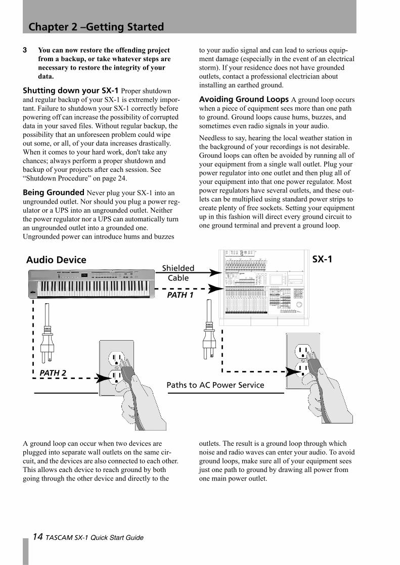
Avoiding Ground Loops A ground loop occurs when a piece of equipment sees more than one path to ground. Ground loops cause hums, buzzes, and sometimes even radio signals in your audio.Needless to say, hearing the local weather station in the background of your recordings is not desirable. Ground loops can often be avoided by running all of your equipment from a single wall outlet. Plug your power regulator into one outlet and then plug all of your equipment into that one power regulator. Most power regulators have several outlets, and these out-lets can be multiplied using standard power strips to create plenty of free sockets. Setting your equipment up in this fashion will direct every ground circuit to one ground terminal and prevent a ground loop.
A ground loop can occur when two devices are plugged into separate wall outlets on the same cir-cuit, and the devices are also connected to each other. This allows each device to reach ground by both going through the other device and directly to the
outlets. The result is a ground loop through which noise and radio waves can enter your audio. To avoid ground loops, make sure all of your equipment sees just one path to ground by drawing all power from one main power outlet.
14 TASCAM SX-1 Quick Start Guide
Chapter 3 – Making Connections
Getting Sound
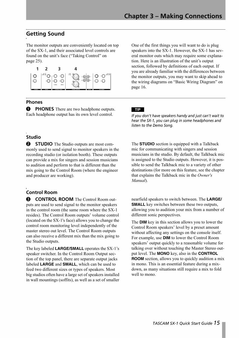
The monitor outputs are conveniently located on top of the SX-1, and their associated level controls are found on the unit’s face (“Taking Control” on page 25).
One of the first things you will want to do is plug speakers into the SX-1. However, the SX-1 has sev-eral monitor outs which may require some explana-tion. Here is an illustration of the unit’s output section, followed by definitions of each output. If you are already familiar with the differences between the monitor outputs, you may want to skip ahead to the wiring diagrams on “Basic Wiring Diagram” on page 16.
Phones1 PHONES There are two headphone outputs. Each headphone output has its own level control.
TIP
If you don't have speakers handy and just can't wait to hear the SX-1, you can plug in some headphones and listen to the Demo Song.
Studio2 STUDIO The Studio outputs are most com-monly used to send signal to monitor speakers in the recording studio (or isolation booth). These outputs can provide a mix for singers and session musicians to audition and perform to that is different than the mix going to the Control Room (where the engineer and producer are working).
The STUDIO section is equipped with a Talkback mic for communicating with singers and session musicians in the studio. By default, the Talkback mic is assigned to the Studio outputs. However, it is pos-sible to send the Talkback mic to a variety of other destinations (for more on this feature, see the chapter that explains the Talkback mic in the Owner's Manual).
Control Room3 CONTROL ROOM The Control Room out-puts are used to send signal to the monitor speakers in the control room (the same room where the SX-1 resides). The Control Room outputs’ volume control (located on the SX-1's face) allows you to change the control room monitoring level independently of the master stereo out level. The Control Room outputs can also receive a different mix than the mix going to the Studio outputs.The key labeled LARGE/SMALL operates the SX-1’s speaker switcher. In the Control Room Output sec-tion of the top panel, there are separate output jacks labeled LARGE and SMALL, which can be used to feed two different sizes or types of speakers. Most big studios often have a large set of speakers installed in wall mountings (soffits), as well as a set of smaller
nearfield speakers to switch between. The LARGE/SMALL key switches between these two outputs, allowing you to audition your mix from a number of different sonic perspectives.The DIM key in this section allows you to lower the Control Room speakers’ level by a preset amount without affecting any settings on the console itself. For example, use DIM to lower the Control Room speakers’ output quickly to a reasonable volume for talking over without touching the Master Stereo out-put level. The MONO key, also in the CONTROL ROOM section, allows you to quickly audition a mix in mono. This is an essential feature during a mix-down, as many situations still require a mix to fold well to mono.
1 2 3 4
TASCAM SX-1 Quick Start Guide 15
Chapter 3 –Making Connections
Master Stereo Outs4 MASTER STEREO OUTS There are two sets of stereo outputs: balanced XLR and unbalanced RCA. The level of these outputs is controlled by the MASTER fader, found on the SX-1's control surface. These outputs are normally used to send a stereo sig-nal to 2-track recording devices such as a TASCAM
DA-45HR DAT deck (but they can be configured on the routing pages).The Master output is separate from the Studio and Control Room outs so that you can adjust your moni-toring levels independently, without affecting the level going from the Master out to a 2-track mix-down deck.
Basic Wiring Diagram
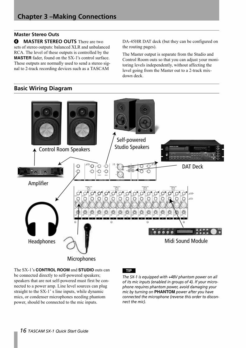
The SX-1’s CONTROL ROOM and STUDIO outs can be connected directly to self-powered speakers; speakers that are not self-powered must first be con-nected to a power amp. Line level sources can plug straight to the SX-1’ s line inputs, while dynamic mics, or condenser microphones needing phantom power, should be connected to the mic inputs.
TIP
The SX-1 is equipped with +48V phantom power on all of its mic inputs (enabled in groups of 4). If your micro-phone requires phantom power, avoid damaging your mic by turning on PHANTOM power after you have connected the microphone (reverse this order to discon-nect the mic).
16 TASCAM SX-1 Quick Start Guide
Chapter 3 –Making Connections
Important Rear Connections
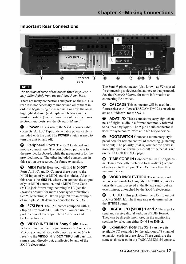
NOTE
The position of some of the boards fitted in your SX-1 may differ slightly from the positions shown here..
There are many connections and ports on the SX-1’ s rear. It is not necessary to understand all of them in order to begin using the machine. For now, the areas highlighted above (and explained below) are the most important. (To learn more about the other con-nections and ports, see the Owner’s Manual.)
1 Power This is where the SX-1’s power cable connects. An IEC Type II detachable power cable is included with the unit. The POWER switch is used to turn the unit on and off.
2 Peripheral Ports The PS/2 keyboard and mouse connect here. The port colored purple is for the provided keyboard, while the green port is for the provided mouse. The other included connections in this section are reserved for future expansion.
3 MIDI Ports Here you will find MIDI OUT Ports A, B, C, and D. Connect these ports to the MIDI inputs of your MIDI sound modules. Also in this area is the MIDI IN, where you connect the output of your MIDI controller, and a MIDI Time Code (MTC) jack for reading incoming MTC (see the Owner’s Manual for more about synchronization). See “Connecting MIDI” on page 20 for an example of multiple MIDI devices connected to the SX-1.
4 SCSI Port The SX1 comes equipped with a 68-pin Ultra Wide SCSI interface. You can use this port to connect to compatible SCSI drives and backup solutions.
5 VIDEO IN/THRU & Sony 9-pin These jacks are involved with synchronization. Connect a Video sync signal (also called house sync or black-burst) to the VIDEO IN. VIDEO THRU will pass that same signal directly out, unaffected by any of the SX-1’s electronics.
The Sony 9-pin connector (also known as P2) is used for connecting to devices that adhere to that protocol. See the Owner’s Manual for more information on connecting P2 devices.
6 CASCADE This connector will be used in a future release to allow a TASCAM DM-24 console to act as a “sidecar” for the SX-1.
7 ADAT I/O These connectors carry eight chan-nels of digital audio in a format commonly referred to as ADAT lightpipe. The 9-pin D-sub connector is used for sync/control with an ADAT-style device.
8 FOOTSWITCH Connect a momentary-style pedal here for remote control of recording (punching in or out). The polarity (that is, whether the pedal is normally open or normally closed) of the pedal is set on the LCD PREFERENCES page.
9 TIME CODE IN Connect the LTC (Longitudi-nal Time Code, often referred to as SMPTE) output of a device to this input. The SX-1 can chase this incoming code.
A WORD IN/OUT/THRU These jacks send and receive word clock signals. The THRU connector takes the signal received at the IN and sends out an exact mirror, untouched by the SX-1’s electronics.
B LTC OUT This jack allows the SX-1 to output LTC (or SMPTE). The frame rate is determined on the SETTINGS pages.
C DIGITAL I/O (SPDIF) 1 and 2 These jacks send and receive digital audio in S/PDIF format. They can be directly monitored in the monitoring sections by selecting either D-IN 1 or D-IN 2.
D Expansion slots The SX-1 can have its available I/O expanded by the addition of 8-channel expansion cards in these slots. These cards are the same as those used in the TASCAM DM-24 console.
1 2 4 B 6 7 89 A C
3
D
5VGA port
Ethernet port
TASCAM SX-1 Quick Start Guide 17
Chapter 3 –Making Connections
18
Loading the Demo Song
The SX-1 ships with two demonstration songs: an audio and a MIDI demonstration. If your monitors are connected properly, you can load the song as described here, press PLAY and you hear the song.Note that when you load either of the demo songs, the actual demo song does not load. What happens is that the SX-1 automatically makes a copy of the song and loads that copy instead (meaning that there is always a “clean” demonstration song available). If
you want to keep the copy after you have worked on it, unless you save it with another name (which does not include “Demo” as part of the name!), it will be overwritten next time you load the demo song.
TIP
For the following examples, if you are using an external VGA, make sure the MAIN DISPLAY key above the LCD ACCESS section is set to <EXTERNAL> (this LED is lit).
Loading the Audio Demo Song
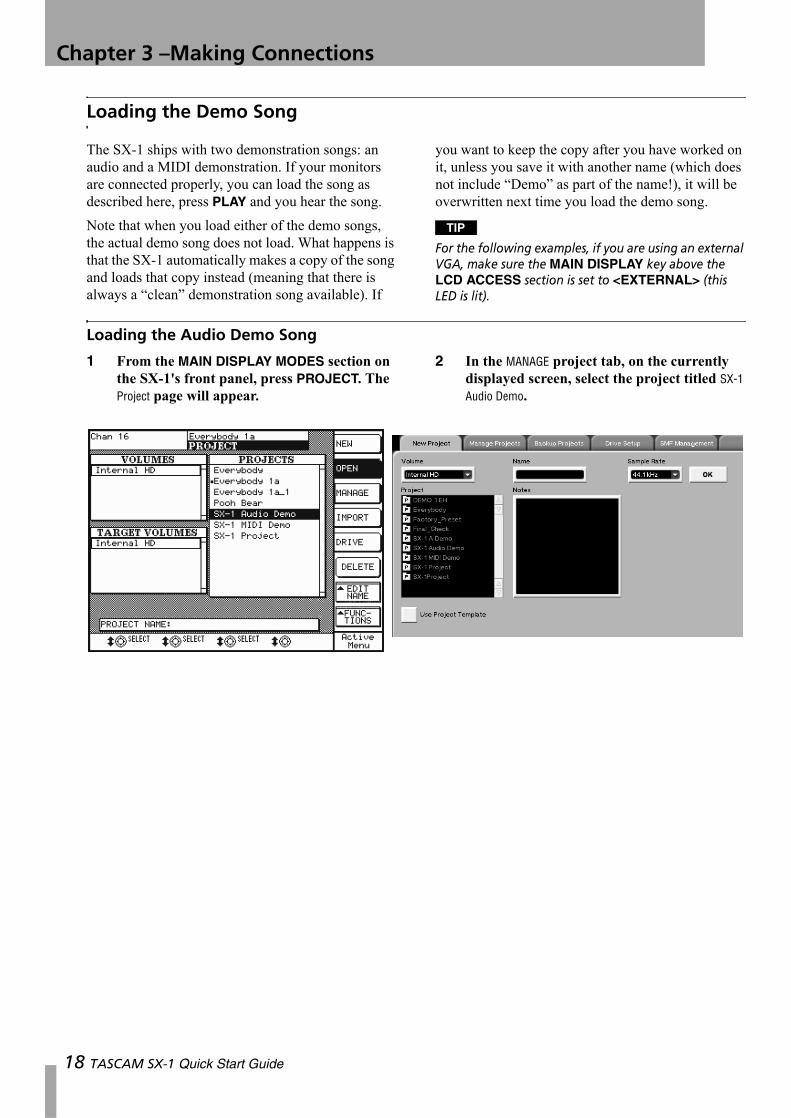
1 From the MAIN DISPLAY MODES section on the SX-1's front panel, press PROJECT. The Project page will appear.
2 In the MANAGE project tab, on the currently displayed screen, select the project titled SX-1 Audio Demo.
TASCAM SX-1 Quick Start Guide
Chapter 3 –Making Connections
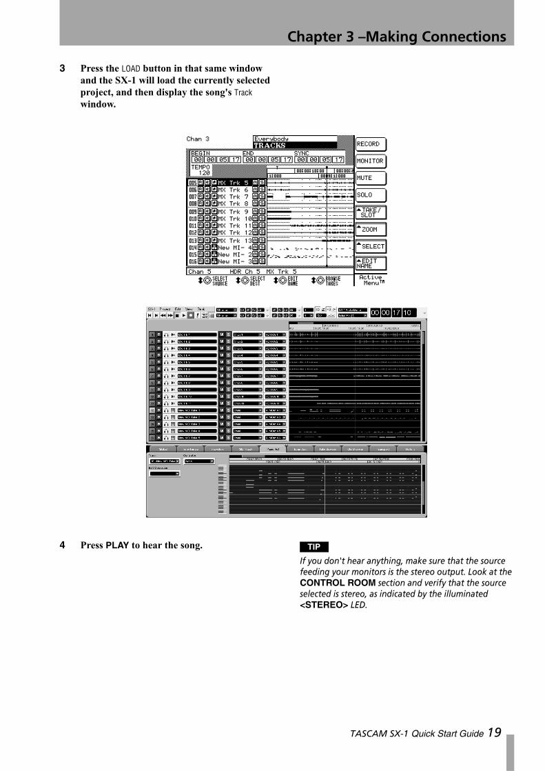
3 Press the LOAD button in that same window and the SX-1 will load the currently selected project, and then display the song's Track window.
4 Press PLAY to hear the song. TIP
If you don't hear anything, make sure that the source feeding your monitors is the stereo output. Look at the CONTROL ROOM section and verify that the source selected is stereo, as indicated by the illuminated <STEREO> LED.
TASCAM SX-1 Quick Start Guide 19
Chapter 4 – MIDI Basics
Connecting MIDI
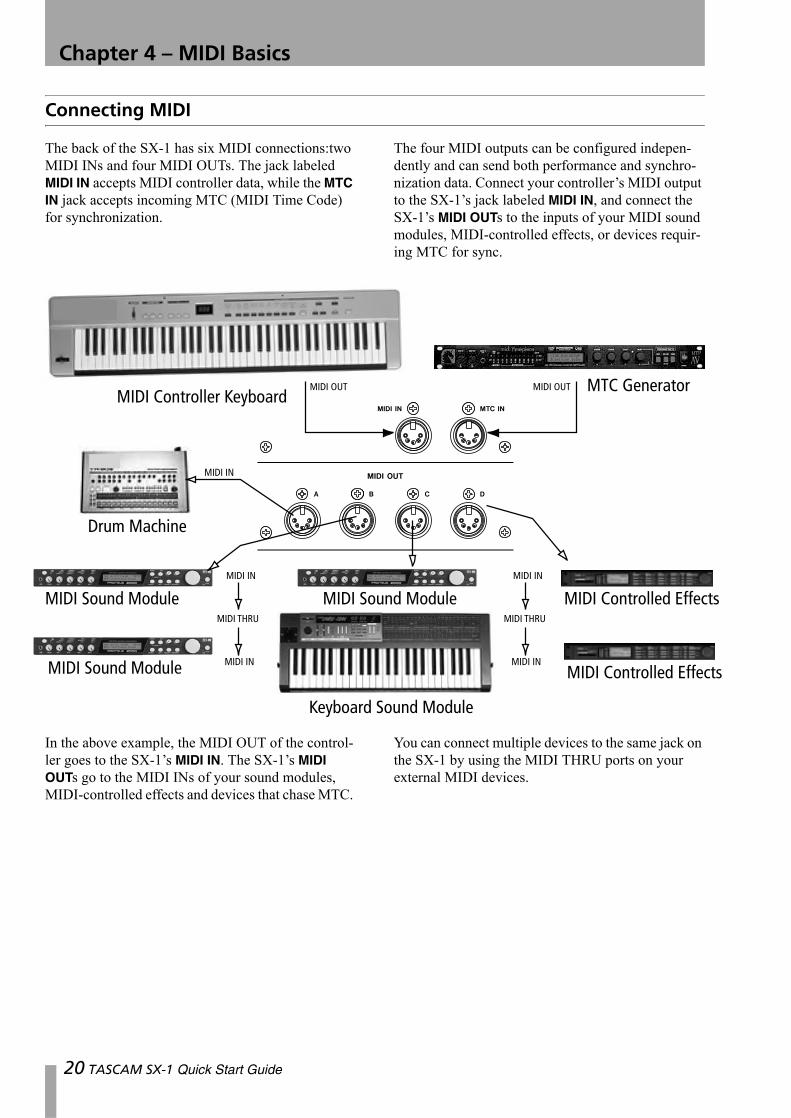
The back of the SX-1 has six MIDI connections:two MIDI INs and four MIDI OUTs. The jack labeled MIDI IN accepts MIDI controller data, while the MTC IN jack accepts incoming MTC (MIDI Time Code) for synchronization.
The four MIDI outputs can be configured indepen-dently and can send both performance and synchro-nization data. Connect your controller’s MIDI output to the SX-1’s jack labeled MIDI IN, and connect the SX-1’s MIDI OUTs to the inputs of your MIDI sound modules, MIDI-controlled effects, or devices requir-ing MTC for sync.
In the above example, the MIDI OUT of the control-ler goes to the SX-1’s MIDI IN. The SX-1’s MIDI OUTs go to the MIDI INs of your sound modules, MIDI-controlled effects and devices that chase MTC.
You can connect multiple devices to the same jack on the SX-1 by using the MIDI THRU ports on your external MIDI devices.
20 TASCAM SX-1 Quick Start Guide
Chapter 4 –MIDI Basics
Loading the MIDI Song Demo
In the same way that the SX-1 makes a copy of the audio demonstration piece, the MIDI demonstration is also copied automatically and the copy is then loaded (preserving the demonstration song). If you change the demonstration, and want to keep it, you must save the project under a different name other-wise it will be overwritten next time you load the demonstration piece.
1 From the MAIN DISPLAY MODES section on the SX-1's front panel, press PROJECT. The Project page will appear (“Loading the Audio Demo Song” on page 18).
2 In the Manage Projects tab, on the currently dis-played screen, select the project titled, SX-1 MIDI Demo.
3 Press the LOAD button in that same window and the SX-1 will load the currently selected project, and then display the song's Track window.
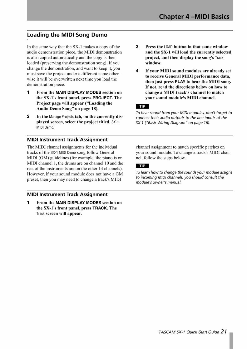
4 If your MIDI sound modules are already set to receive General MIDI performance data, then just press PLAY to hear the MIDI song. If not, read the directions below on how to change a MIDI track's channel to match your sound module's MIDI channel.
TIP
To hear sound from your MIDI modules, don’t forget to connect their audio outputs to the line inputs of the SX-1 (“Basic Wiring Diagram” on page 16).
MIDI Instrument Track AssignmentThe MIDI channel assignments for the individual tracks of the SX-1 MIDI Demo song follow General MIDI (GM) guidelines (for example, the piano is on MIDI channel 1, the drums are on channel 10 and the rest of the instruments are on the other 14 channels). However, if your sound module does not have a GM preset, then you may need to change a track's MIDI
channel assignment to match specific patches on your sound module. To change a track's MIDI chan-nel, follow the steps below.
TIP
To learn how to change the sounds your module assigns to incoming MIDI channels, you should consult the module's owner's manual.
MIDI Instrument Track Assignment
1 From the MAIN DISPLAY MODES section on the SX-1's front panel, press TRACK. The Track screen will appear.
TASCAM SX-1 Quick Start Guide 21
Chapter 4 –MIDI Basics
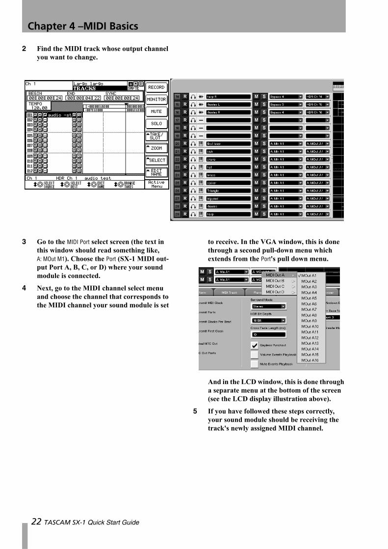
2 Find the MIDI track whose output channel you want to change.
3 Go to the MIDI Port select screen (the text in this window should read something like, A: MOut M1). Choose the Port (SX-1 MIDI out-put Port A, B, C, or D) where your sound module is connected.
4 Next, go to the MIDI channel select menu and choose the channel that corresponds to the MIDI channel your sound module is set
to receive. In the VGA window, this is done through a second pull-down menu which extends from the Port's pull down menu.
And in the LCD window, this is done through a separate menu at the bottom of the screen (see the LCD display illustration above).
5 If you have followed these steps correctly, your sound module should be receiving the track's newly assigned MIDI channel.
22 TASCAM SX-1 Quick Start Guide
Chapter 5 – Essential Moves
Back Up and Shutdown
Proper shutdown and regular backup of your SX-1 is extremely important. Failure to shut down your SX-1 correctly before powering off can increase the possi-bility of corrupted data in your saved files. Without regular backup, the possibility that an unforeseen
problem could wipe out some, or all, of your data increases drastically. When it comes to your hard work, don't take any chances; always perform a proper shut down and backup of your projects after each session.
Backing UpThere are many different ways of backing up, using different types of media (for more on this subject, see the Owner's Manual ). However, one of the simplest and most convenient ways to back up is to use the
SX-1's onboard CD-R burner. Follow the steps below to find out just how easy it is.
TIP HOT TIP! —
We recommend using TEAC brand CD recordable media for all your CD-R needs.
From the VGA screen
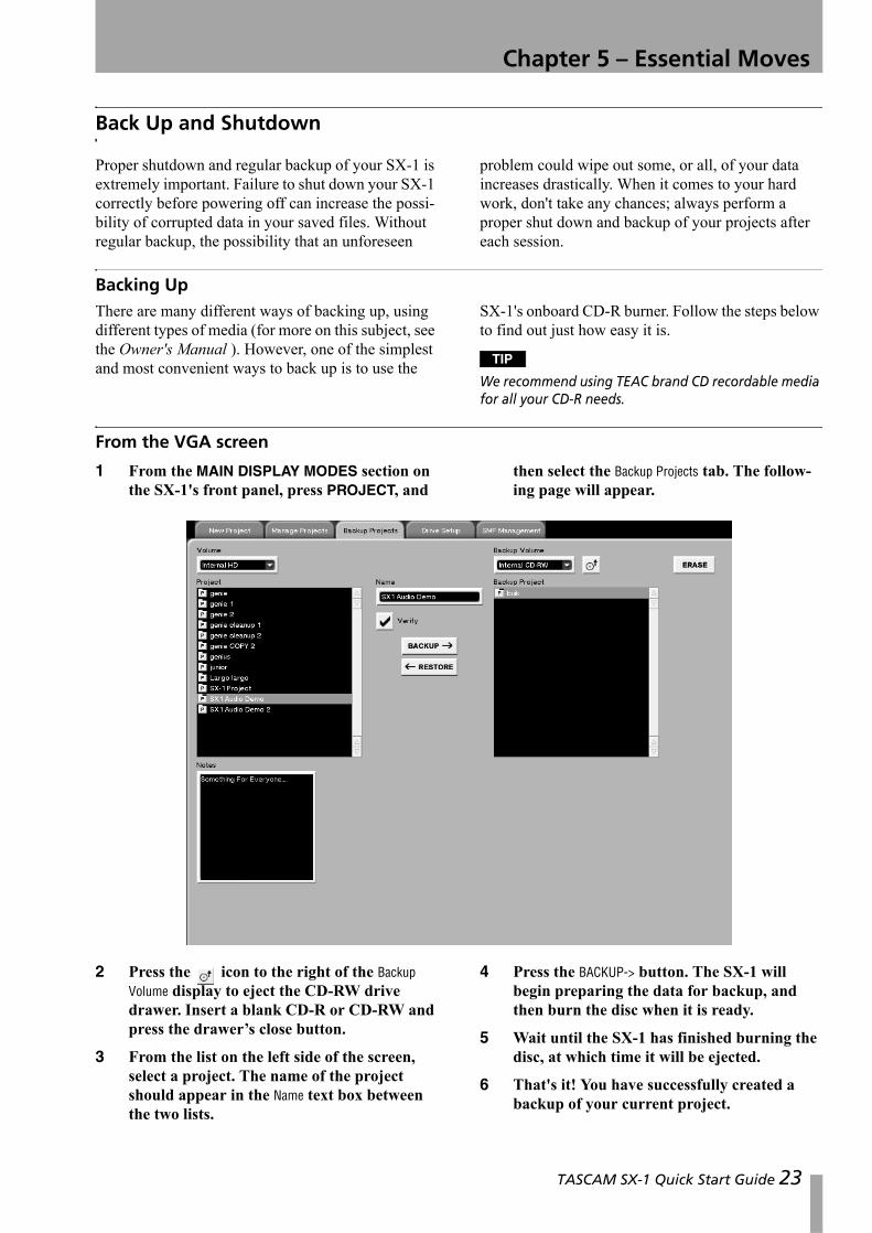
1 From the MAIN DISPLAY MODES section on the SX-1's front panel, press PROJECT, and
then select the Backup Projects tab. The follow-ing page will appear.
2 Press the icon to the right of the Backup Volume display to eject the CD-RW drive drawer. Insert a blank CD-R or CD-RW and press the drawer’s close button.
3 From the list on the left side of the screen, select a project. The name of the project should appear in the Name text box between the two lists.
4 Press the BACKUP-> button. The SX-1 will begin preparing the data for backup, and then burn the disc when it is ready.
5 Wait until the SX-1 has finished burning the disc, at which time it will be ejected.
6 That's it! You have successfully created a backup of your current project.
TASCAM SX-1 Quick Start Guide 23
Chapter 5 –Essential Moves
NOTE
Check the Verify checkbox to ensure that the data backed up is the same as is stored on the SX-1’s hard disk. Since the verify operation performs a bit-by-bit
comparison after the backup has been made, any backup with the verify checkbox set will take twice as long as a backup without the verify operation.
From the LCD screen
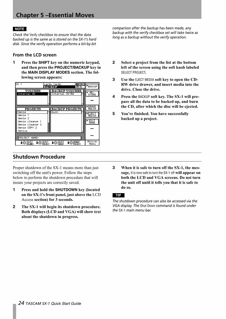
1 Press the SHIFT key on the numeric keypad, and then press the PROJECT/BACKUP key in the MAIN DISPLAY MODES section. The fol-lowing screen appears:
2 Select a project from the list at the bottom left of the screen using the soft knob labeled SELECT PROJECT.
3 Use the EJECT MEDIA soft key to open the CD-RW drive drawer, and insert media into the drive. Close the drive.
4 Press the BACKUP soft key. The SX-1 will pre-pare all the data to be backed up, and burn the CD, after which the disc will be ejected.
5 You’re finished. You have successfully backed up a project.
Shutdown Procedure
Proper shutdown of the SX-1 means more than just switching off the unit's power. Follow the steps below to perform the shutdown procedure that will insure your projects are correctly saved.
1 Press and hold the SHUTDOWN key (located on the SX-1's front panel, just above the LCD Access section) for 3 seconds.
2 The SX-1 will begin its shutdown procedure. Both displays (LCD and VGA) will show text about the shutdown in progress.
3 When it is safe to turn off the SX-1, the mes-sage, It is now safe to turn the SX-1 off will appear on both the LCD and VGA screens. Do not turn the unit off until it tells you that it is safe to do so.
TIP
The shutdown procedure can also be accessed via the VGA display. The Shut Down command is found under the SX-1 main menu bar.
24 TASCAM SX-1 Quick Start Guide
Chapter 6 – Taking Control
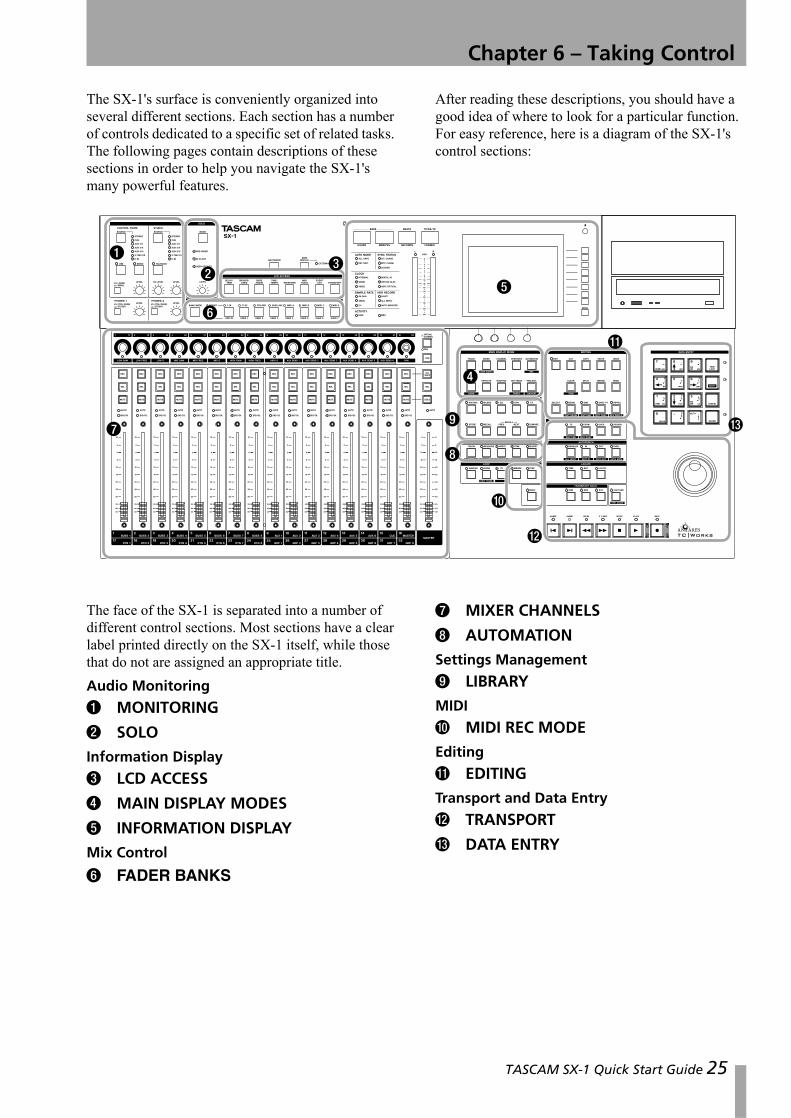
The SX-1's surface is conveniently organized into several different sections. Each section has a number of controls dedicated to a specific set of related tasks. The following pages contain descriptions of these sections in order to help you navigate the SX-1's many powerful features.
After reading these descriptions, you should have a good idea of where to look for a particular function. For easy reference, here is a diagram of the SX-1's control sections:
The face of the SX-1 is separated into a number of different control sections. Most sections have a clear label printed directly on the SX-1 itself, while those that do not are assigned an appropriate title.Audio Monitoring
1 MONITORING
2 SOLO
Information Display
3 LCD ACCESS
4 MAIN DISPLAY MODES
5 INFORMATION DISPLAY
Mix Control
6 FADER BANKS
7 MIXER CHANNELS
8 AUTOMATION
Settings Management
9 LIBRARY
MIDI
A MIDI REC MODE
Editing
B EDITING
Transport and Data Entry
C TRANSPORT
D DATA ENTRY
1
23
4
5
6
7
8
9
A
B
C
D
TASCAM SX-1 Quick Start Guide 25
Chapter 6 –Taking Control
Audio Monitoring1 MONITORING The level and source select (such as master output, cue, auxiliary, or digital input) controls for the STUDIO and CONTROL ROOM outputs are in this section. There is a speaker select button for the CONTROL ROOM that allows quick switching between two different sets of moni-tors (which are fed by the Large and Small
CONTROL ROOM outs). Control for the SX-1's onboard talkback mic is in the STUDIO section.
2 SOLO In this section you will find a level knob for the Solo feature, and a key for selecting the Solo Mode: PRE-FADER, IN-PLACE, or USER-DEFINED (AFL) (these modes are explained in the Owner's Manual).
Information Display3 LCD ACCESS The keys in this section recall screens that are specific to the LCD display. Screens include: bus assignment, track waveform, MIDI information, and channel trim (these screens are explained in the Owner's Manual). These screens are in addition to those available through the MAIN DISPLAY MODES section and can be accessed independently of the current VGA screen. For example, the VGA can display the Track screen, and at the same time, the LCD can display Routing (for true dual monitor behavior, set the MAIN DISPLAY button to <INTERNAL>).
4 MAIN DISPLAY MODES This section's keys select the screen you are viewing on your exter-nal VGA and the LCD.Examples of these screens include: the main track screen, mixer overview, individual mixer channels,
input/output routing, and project management (which are explained in detail in the Owner's Manual). The MAIN DISPLAY MODES section gives you all of the most frequently accessed screens in one convenient location.
5 Information Display This section is not actually labeled Information Display on the SX-1. However, that title best describes this area. Here you will find the LCD, stereo meters, and a variety of LED indicators (for example, synchronization and clock status, and hard disk and MIDI activity indica-tors). Surrounding the big LCD are several “soft” knobs and keys (see “LCD Screen Navigation” on page 10), whose functions change depending on the LCD’s current screen. The individual LED indicators in this section are covered in the Owner's Manual.
Mix Control6 FADER BANKS Use the keys in this section to choose which sources the SX-1's physical faders will control. Preset fader banks include: input chan-nels 1-16 and 17-32, group returns 1-8, auxiliary bus-ses 1-8, and MIDI channels 1-16 for each MIDI Out port (A, B, C, and D). Up to 7 user defined fader banks can also be created.
7 MIXER CHANNELS This section is not actu-ally labeled Mixer Channels on the SX-1. However, that title best describes this area of the SX-1's face.
Here you will find the 16 channel strips and all their associated controls (faders, pan pots, mute/solo switches, record enable keys, etc.) and the master fader. The Mixer Channels section is covered in detail in the Owner's Manual.
8 AUTOMATION This section contains the keys for utilizing automation. Here you can enable a variety of automation modes (such as write, touch and trim). For definitions of the automation modes, see the Owner's Manual.
Settings Management9 LIBRARY When you create a new setting (an effect or EQ, for example), it is possible to save this setting as a patch for recall at a later time. The keys for saving the settings for a variety of different func-
tions (including all the control elements of the chan-nel strips) reside in the LIBRARY section. For more information about the power of the Library feature, see the Owner's Manual.
26 TASCAM SX-1 Quick Start Guide
Chapter 6 –Taking Control
MIDIA MIDI REC MODE This section accesses the SX-1's Step mode and MIDI Merge function. Just beneath the MIDI REC MODE section is a PANIC but-ton for resetting stuck MIDI devices. See the Owner's Manual for more information about MIDI Recording.
NOTE
The PANIC key is a latching-type key. Press once to enable panic mode (the indicator pulses) and again to disable panic mode.
EditingB EDITING For all your audio waveform and MIDI note editing needs, there is the EDITING sec-tion. Here you will find basic cut, copy, and paste commands, as well as many other advanced editing
commands (such as, ripple, crop, and split). To learn more about the SX-1's extensive audio waveform and MIDI editing capabilities, see the Owner's Manual.
Transport and Data EntryC TRANSPORT Though this area is not actually labeled Transport on the SX-1, that title best describes this section of the SX-1's face. Here you will find a set of standard transport keys (play, stop, record, fast forward, rewind, end jump, and begin-ning jump). Just above the transport keys are controls for capturing and recalling locate points. The SX-1 has many advanced transport functions (including looping, user definable post/pre roll times, and auto punch). As well, the Jog/Shuttle wheel is handy for jogging, scrubbing, and shuttling. To learn
more about these advanced features, see the Owner's Manual.
D DATA ENTRY The numeric keypad is labeled DATA ENTRY. Keys on the numeric keypad are used for entering numbers (and letters) directly into onscreen fields, enabling shifted functions and spe-cial key commands (see “Multi-Function Keys” on page 9), up/down and left/right cursor navigation, and entering MIDI step record note values (see the Owner's Manual for more on the DATA ENTRY section).
TASCAM SX-1 Quick Start Guide 27
Chapter 7 – Basic Moves
Getting Around
Many of today's most popular audio production workstations share similar command sequences.For example, the keystrokes to record a track or copy an audio waveform can be very similar on many computer-based recording systems. The SX-1 fol-lows these same command sequence traditions. If you are familiar with how to operate digital audio sequencers and multi-track recorders, getting around on the SX-1 should feel familiar.
TIP
When using the PS/2 keyboard, the Alt key is used together with other number or letter keys as a shortcut key (as opposed to other systems, which may use the Control or Command keys for this purpose).
If you are unfamiliar with operating this type of recording gear, read the examples on the following pages to learn some of the basic recording moves for the SX-1.
TIP HOT TIP! —
Because we must choose a common starting point from which to explain a procedure, all the following exam-ples assume that the SX-1's factory default settings have not been touched. If you have not changed any of the SX-1's default settings, you should be able to follow right along with all the examples, step by step.
A Quick Explanation of a Few Important Terms
The SX-1 uses a number of terms that apply to differ-ent groups of data, making it extremely important that you have a working knowledge of these in order to manage your work effectively. Once you get the terminology down, the rest should be much easier to understand.
Slot A Slot is a container that Takes can be loaded into (or created on). When a project is first created, the Track screen on either the VGA or LCD will show empty Slots, meaning that no audio or MIDI Takes have yet been created. Slots can be created from scratch, removed, and deleted, and the order may be changed by moving the selected Slot up or down in the list. The important thing to remember is that Slots can be moved or modified with or without loaded Takes, and that anything done to a Slot is done to a Take loaded upon it (meaning that if you delete a Slot, its Take is automatically unloaded).
Take A Take is a Track, or a container that audio Clips and MIDI data are loaded onto for use. Either term (Take or Track) is correct for use on the SX-1. When you give a Take a name, any audio Clip or Clips recorded on that Take use the same name.Takes are loaded into Slots for use on both the Track and the CD burning screens, and can be loaded and unloaded at will. A Take can be loaded only once in a project at a time, which means that if you have data on a Take that you would like to copy to another
location within the same project, you will have to do that operation manually.The thing to remember about Takes is that they are basically self-contained EDLs (Edit Decision Lists—or lists of which parts of the events play back at which time), and not the raw data itself. Another way to visualize the paradigm would be to think of a Take as an ice-cube tray in your freezer, and the raw audio files (or Clips) as the ice-cubes themselves.
Clip A Clip is a raw audio file, created by recording on the hard disk, using the Render command, or importing from an external volume. A Clip is named by the Take it is recorded on, or by using the Render command. Clips contain information regarding bit depth, sam-ple rate, and time stamps—data that is viewable in the VGA Clip Browser by selecting a clip in the list at the left of the screen.
Channel A “mixer Channel” refers to a channel on the mixing console, which is entirely separate from the HDR (in fact, it is not necessary to use the HDR on the SX-1 at all, as all components of the machine work separately). As well, there are no dedicated return channels on the console for the onboard recorder, which the SX-1’s mixer regards as an exter-nal device. Remember that to listen to the HDR, you will need to use 16 of the available 40 input channels on the console. This means that a designation for a “channel” is con-text-sensitive, or rather that “a channel” might refer
28 TASCAM SX-1 Quick Start Guide
Chapter 7 –Basic Moves
to a mixer channel, a MIDI channel, or an HDR channel.
Mutes and Solos Mutes and Solos work as expected from the surface, but it should be noted that the Take Mute and Solo buttons ( and ) on the VGA’s Track screen do not have any interaction with the surface keys when operating an audio channel.
As the SX-1’s mixer regards the HDR as a separate device, the Take Mute and Solo keys operate for Takes only. Pressing a Take Solo or Mute button will mute or solo that Take, and not a mixer channel. Think of the Take Mute and Solo buttons on the VGA or LCD Track screen as mutes or solos for your hard disk recorder, and not for the rest of your system.
Creating a New Project
The SX-1 automatically saves the last project you were working on when you perform the Shutdown procedure. It will also automatically reload that last project when it is turned back on.
Follow the steps below to create an entirely new project.
On the VGA
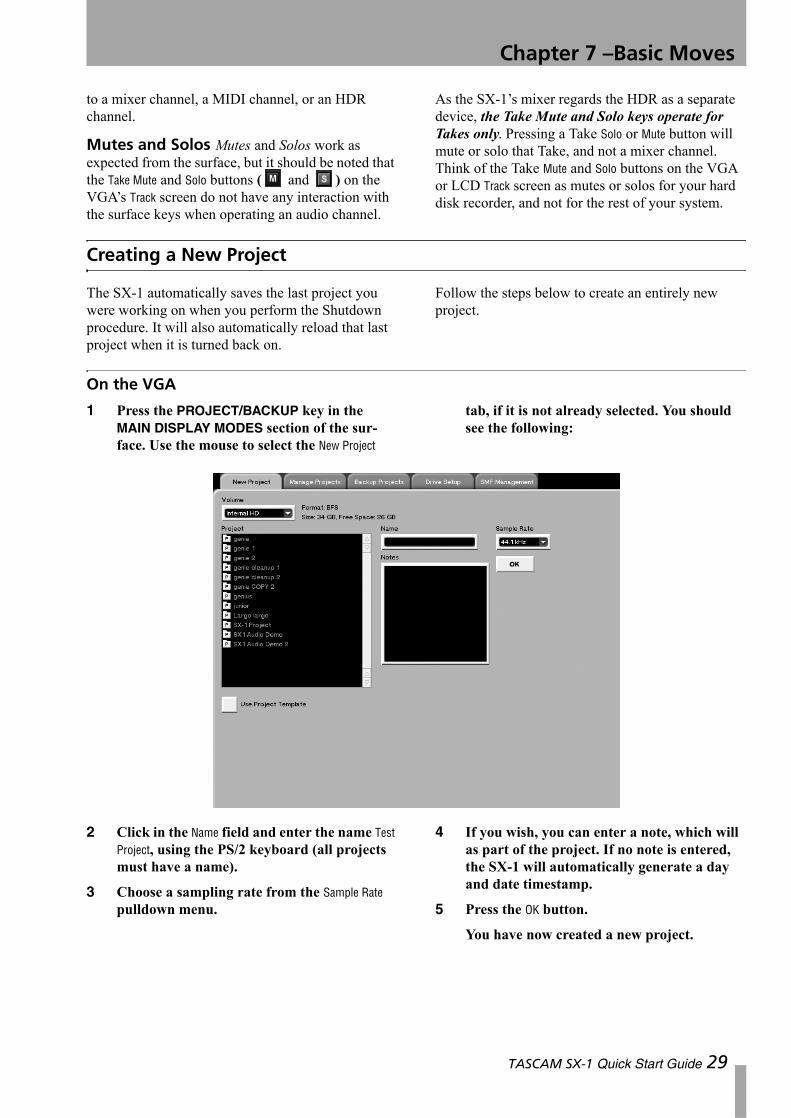
1 Press the PROJECT/BACKUP key in the MAIN DISPLAY MODES section of the sur-face. Use the mouse to select the New Project
tab, if it is not already selected. You should see the following:
2 Click in the Name field and enter the name Test Project, using the PS/2 keyboard (all projects must have a name).
3 Choose a sampling rate from the Sample Rate pulldown menu.
4 If you wish, you can enter a note, which will as part of the project. If no note is entered, the SX-1 will automatically generate a day and date timestamp.
5 Press the OK button.
You have now created a new project.
TASCAM SX-1 Quick Start Guide 29
Chapter 7 –Basic Moves
On the LCD
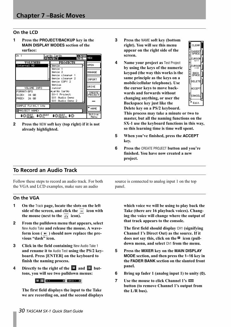
1 Press the PROJECT/BACKUP key in the MAIN DISPLAY MODES section of the surface:
2 Press the NEW soft key (top right) if it is not already highlighted.
3 Press the NAME soft key (bottom right). You will see this menu appear on the right side of the screen.
4 Name your project as Test Project by using the keys of the numeric keypad (the way this works is the same principle as the keys on a mobile/cellular telephone). Use the cursor keys to move back-wards and forwards without changing anything, or user the Backspace key just like the Delete key on a PS/2 keyboard. This process may take a minute or two to master, but all the naming functions on the SX-1 use the keyboard functions in this way, so this learning time is time well spent.
5 When you’ve finished, press the ACCEPT key.
6 Press the CREATE PROJECT button and you’re finished. You have now created a new project.
To Record an Audio Track
Follow these steps to record an audio track. For both the VGA and LCD examples, make sure an audio
source is connected to analog input 1 on the top panel.
On the VGA
1 On the Track page, locate the slots on the left side of the screen, and click the icon with the mouse (next to the icon).
2 From the pulldown menu that appears, select New Audio Take and release the mouse. A wave-form icon ( ) should now replace the pre-vious “dash” icon.
3 Click in the field containing New Audio Take 1 and rename it to Audio Test using the PS/2 key-board. Press [ENTER] on the keyboard to finish the naming process.
4 Directly to the right of the and but-tons, you will see two pulldown menus:
The first field displays the input to the Take we are recording on, and the second displays
which voice we will be using to play back the Take (there are 16 playback voices). Chang-ing the voice will change where the output of that track appears to the console.
The first field should display CH1 (signifying Channel 1’s Direct Out) as the source. If it does not say this, click on the icon (pull-down menu, and select Ch1 from the menu.
5 Press the MIXER key on the MAIN DISPLAY MODE section, and then press the 1–16 key in the FADER BANK section on the slanted front panel.
6 Bring up fader 1 (analog input 1) to unity (0).
7 Use the mouse to click Channel 1’s button (to remove Channel 1’s output from the L/R bus).
30 TASCAM SX-1 Quick Start Guide
Chapter 7 –Basic Moves
NOTE
You are doing this so that you can monitor the signal off the HDR’s output. Leaving Channel 1 feeding the L/R bus, at the same time that it is feeding the input to a Take that is record-enabled, will result in phasing of the signal. Phasing is a time-delay related anomaly that results when a signal from a source arrives at the listen-ing position from two different distances (causing some frequencies to cancel each other out). It is a nasty, unpleasant-sounding thing in most cases…
8 Navigate back to the Track screen.
9 Record-enable your Take; either by pressing the button to the left of the icon, or by pressing the REC arm key for channel 17 on the surface.
10 Bring up fader 17 (which is HDR 1 return) to unity (0).
11 Adjust the level using the analog input GAIN knob on the top panel of the SX-1.
12 Press PLAY and RECORD, and make some recordable sounds with your sound source.
13 After a few seconds, press STOP and you should see the waveform appear on Audio Test.
On the LCD
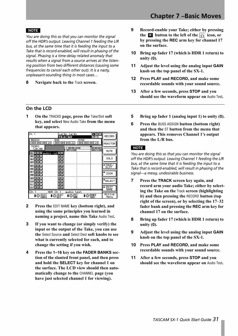
1 On the TRACKS page, press the Take/Slot soft key, and select New Audio Take from the menu that appears.
2 Press the EDIT NAME key (bottom right), and using the same principles you learned in naming a project, name this Take Audio Test.
3 If you want to change (or simply verify) the input or the output of the Take, you can use the Select Source and Select Dest soft knobs to see what is currently selected for each, and to change the setting if you wish.
4 Press the 1–16 key on the FADER BANKS sec-tion of the slanted front panel, and then press and hold the SELECT key for channel 1 on the surface. The LCD view should then auto-matically change to the CHANNEL page (you have just selected channel 1 for viewing).
5 Bring up fader 1 (analog input 1) to unity (0).
6 Press the BUSS ASSIGN button (bottom right) and then the ST button from the menu that appears. This removes Channel 1’s output from the L/R bus.
NOTE
You are doing this so that you can monitor the signal off the HDR’s output. Leaving Channel 1 feeding the L/R bus, at the same time that it is feeding the input to a Take that is record-enabled, will result in phasing of the signal—a messy, undesirable business.
7 Press the TRACK screen key again, and record arm your audio Take; either by select-ing the Take on the Track screen (highlighting it) and then pressing the RECORD button (top right of the screen), or by selecting the 17–32 fader bank and pressing the REC arm key for channel 17 on the surface.
8 Bring up fader 17 (which is HDR 1 return) to unity (0).
9 Adjust the level using the analog input GAIN knob on the top panel of the SX-1.
10 Press PLAY and RECORD, and make some recordable sounds with your sound source.
11 After a few seconds, press STOP and you should see the waveform appear on Audio Test.
TASCAM SX-1 Quick Start Guide 31
Chapter 7 –Basic Moves
Recording MIDI
For both the following examples, make sure you have the MIDI output of a MIDI controller of some type (keyboard controller, drum machine, guitar synth, etc.) connected to the MIDI IN of the SX-1. Also, make sure you have a sound source available if your controller does not support sounds, and that the SX-1’s MIDI A output jack is connected to this devices’s MIDI IN (if your controller is also your
sound source, just make both connections on the same box).Also, don’t forget to connect the audio output of your sound source to an audio input on the SX-1. For the purposes of this exercise, use analog inputs 3 and 4.These examples use the Test Project set up earlier.
On the VGA
1 Navigate back to the Track screen, and click the icon on the next slot down from Audio Take with the mouse (next to the icon).
2 Select New MIDI Take from the pulldown menu, and release the mouse button.
3 Name your MIDI Take as MIDI Test, and select OMNI as the MIDI input to this Take if it is not already selected.
4 Select the one of the 16 channels on MIDI Out A that you want to use. If you are not using a multi-timbral sound source (meaning that it can only play back one sound at a time), select A: MOut M1.
5 Record arm your MIDI Take; either by pressing the button to the left of the icon, or by pressing the MIDI A key in the
FADER BANKS section of the slanted front panel, and then pressing the REC arm key for MIDI A Channel 1.
6 Make sure you have remembered to bring up the audio faders where your sound source is returning, so that you can hear your MIDI source. You connected your source to analog inputs 3 and 4, so select the 1–16 fader bank, and bring up the faders for channels 3 and 4.
7 With your channel record armed, you should be able to play notes on your controller and hear them through the console.
8 Press PLAY and RECORD, and play some notes on your controller. They should appear instantly on the MIDI Test Take.
On the LCD
1 On the Track screen, use the keypad’s cursor keys to select the slot beneath Audio Test, and press the TAKE/SLOT soft key.
2 Select New MIDI Take from the menu that appears.
3 Using the Select Source soft knob, select Omni as the input source. Using the Select Dest knob, select MIDI OUT A Mout A1 as the destination.
4 Record-arm your Take, either by pressing the RECORD button (upper right) on the Track screen, or by pressing the MIDI A key in the FADER BANK section, and immediately pressing the REC key of MIDI A Channel 1 (the first fader).
5 Make sure you have raised the audio channel 3 and 4 faders (where your sound source is coming into the console) so that you can hear it.
6 With your Take record-enabled, you should now be able to hear your MIDI device when you play it.
7 Press PLAY and RECORD and play some-thing on your MIDI controller. You should see MIDI data immediately written on MIDI Test.
32 TASCAM SX-1 Quick Start Guide
Chapter 7 –Basic Moves
Using Locate Points and Autopunch
Locate points enable you to navigate through a project quickly and easily, which is an absolute necessity when speed is important. Follow the steps here to learn how to store and recall locate points, as well as how to use the autopunch facilities.
A word about the CAPTURE key The opera-tion of the SX-1’s CAPTURE key may require a bit of explanation for some users. When the key is pressed, the location of the playhead (its current time value, whether or not the transport is moving) is
“captured” and held. Once captured, that time loca-tion can be stored in a number of places. These avail-able registers flash when a value is captured, letting you know that you can store the time value there. Possible locations for captured values include locate points, auto punch points, edit points and loop points.The main concept to understand is that the time value is captured by pressing the CAPTURE key, not when you store that value in one of the available registers. The paradigm in the following instructions works the same for all types of storable points on the machine.
Setting a locate point
1 Move the transport to your desired location.
2 Press CAPTURE in the LOCATE section of the surface.
You will notice that a number of indicators flash in various places, letting you know that the time value you just captured can be stored in any of them.
3 Press the LOCATE key in the LOCATE section.
4 Press a number on the numeric keypad and then press the ENTER key.
5 You have just saved a locate point.
Recalling a Locate Point
1 Press the LOCATE key in the LOCATE section of the surface.
2 Press a number that corresponds to a stored point and press ENTER on the keypad.
3 The transport will be moved to that time location.
TIP
You will notice that pressing the LOCATE key will always come up with the last point chosen. You can use this as a quick return point, as no matter how far you fast forward, rewind or play, the last point you chose will always come up first.
Using Autopunch
Autopunch allows the SX-1 to perform automated punch in and punch out at defined points.The following steps explain how to use Autopunch.
1 Cue the SX-1’s transport to the spot where you would like to punch in (or enter record).
2 Press CAPTURE.
3 Assign the captured value as the punch in point by pressing the IN key in the AUTOPUNCH section of the surface.
4 Cue the transport to the spot where you would like to punch out (or exit recording).
5 Press the CAPTURE key again.
6 Assign the captured value as the punch out point by pressing the OUT key in the AUTOPUNCH section.
7 Enable Autopunch by pressing the ENABLED key in the AUTOPUNCH section. You will notice that the RECORD key flashes as an additional indication.
8 Record-arm the Take you will be recording on.
TASCAM SX-1 Quick Start Guide 33
Chapter 7 –Basic Moves
9 Cue the transport to a spot before the punch in point, and press PLAY (you do not have to press RECORD). When the transport passes the punch in point, it will enter record mode. When it passes the punch out point, it will exit record mode.
Updating the SX-1 software
From time to time you may need to install or update the software in the SX-1. TASCAM will send you software installation CDs when a new version becomes available.Follow the steps below to install or update your sys-tem software:
1 Eject the CD-RW drive tray. If there is noth-ing in the drive, you can press the small but-ton on the lower right side of the front of the drive itself to eject the tray. If a disc is already loaded, navigate to one of the screens (Master, Project) that has an eject button and use that.
2 Insert the software CD-ROM into the drive and close the tray.
3 Power down the SX-1.
4 When the SX-1 is fully shut down, reboot the machine.
5 The normal boot sequence will be inter-rupted with the software CD-ROM in the drive. A prompt will appear, asking you if
you wish to Install operating system or Update operating system from the CD-ROM. Choosing Install wipes the whole drive, while choosing Update leaves the projects and audio alone, replacing only the system software.
6 Decide which action suits your present situa-tion and make your selection. The SX-1 will install software in the manner you selected.
7 When the installation is finished, click the EXIT button, and remove the CD-ROM from the tray when it pops out. DO THIS QUICKLY, as the tray will close (with or without your fingers) in a few seconds.
8 That’s it. You’ve successfully updated your software.
The SX-1 will restart, displaying a number of mes-sages as it does so. Depending on the software installed, it might need to flash the onboard SH Rom. If so, the SX-1 will display the message updating panel software with a progress report. It may then restart, becoming fully operational on bootup.
34 TASCAM SX-1 Quick Start Guide
Chapter 8 – A quick look at a few shortcuts
The SX-1 is a deep machine, and while it is easy to use, it could be some time before you learn all of its capabilities. The following are short examples of
some time-savers you can use to get a job done quickly.
Make a quick headphone mix.
This short example assumes a few things. It assumes that:1. You have a mix on the faders that sounds good to you.2. You have a pair of headphones connected to the SX-1.
3. Those headphones are being fed by the Cue bus.Holding down the SHIFT key on the numeric keypad, press the CUE key in the virtual channel strip. You have just copied your stereo mix to your Cue mix. You can now move the Cue faders and change the mix slightly to better suit your performers’ needs (perhaps they need click but you don’t, for instance).
Make 5 different mixes for different players quickly
1 Use the previous example as Step One.
2 On the Routing screen, route the outputs of Aux sends 5 and 6 to the Stereo Out jacks on the top panel.
NOTE
This means that you now have all of the Auxs being sent externally: Aux Sends 1-4 are being sent out their default jacks on the top panel, while Aux Sends 5 and 6 are being sent from the Stereo outs (XLR).
3 Use Aux sends 1-6 (in pairs) to make three mixes for your players.
4 Connect the AUX SEND 1-4 and STEREO OUT jacks to an external headphone amplifier.
This means that you now have 5 mixes running at the same time: The Stereo Mix (you are listening to in the Control Room), the Cue Mix (one set of head-phones), Aux 1-2, Aux 3-4, and Aux 5-6. This scenario should cover most live tracking situa-tions for medium-sized ensembles.
Quickly move all of your faders (on the current layer) back to unity.
Holding down the CANCEL key in the numeric key-pad, touch a fader. You will notice that it moves back to unity.
You can hold down CANCEL and run your hand along all the faders to quickly bring them up to unity.
Quickly make a Fader Group
Holding the SHIFT key on the numeric keypad, press any three channel SEL keys on the surface. You have just made a fader group. The channel whose SEL key
you touched first has become the group master, while the next two channels became the slaves.To dissolve the group, simply repeat the above steps.
Quickly Solo-Safe a channel (or channels)
The ability to solo-safe a channel or bus is extremely handy when mixing. Essentially, this enables you to remove a channel from the operation of the solo bus (it does not exempt the channel from mutes, how-ever). This means a channel that is in solo-safe will always be heard unless it is muted.
To solo-safe a channel, first press the SOLO key on the master channel on the surface (which puts the surface into solo ready mode). With the master solo light lit, hold down SHIFT and press a channel’s SOLO key. That channel is now in solo-safe.
TASCAM SX-1 Quick Start Guide 35
Chapter 8 –A quick look at a few shortcuts
This can easily be verified by looking at the VGA’s Mixer screen—the solo buttons of channels in solo safe are no longer green in color, as the rest are.
Quickly link a pair of channels on the console
Simply press the SEL keys for both channels at the same time. Remember, these must be coincident channels (1 and 2, 3 and 4, etc). If you only want to
link certain things, right-click on the LINK button on the Mixer or Channel screens, or go to the LCD Links page.
Quickly mixdown a number of sources to a stereo pair
1 Solo the channels (this can include audio coming into the mixing console from another device) you would like to mix together.
2 Get your balances where you like them. This can include as much automation as you wish.
3 Enable Mixdown mode, but do not select Create Mix. This can be done from the VGA’s Track screen on the Global tab, or from the Mix screen on the LCD.
4 Give the stereo file you’re about to make a name that you’ll remember. You can do this on the same screen from which you enabled Mixdown mode.
5 Cue the transport back to where you would like to begin, and press PLAY and RECORD. Everything coming out of the L/R bus is now being recorded to a separate stereo file (actu-ally two mono Takes).
It is now easy to unload all of the Takes you have just comped together to save space, and load in the new pair. You can re-import these Takes in the same way you would normally load Takes into a project.
Quickly use the LCD and the VGA screens to show separate things
You can use the LCD’s Track screen to show you your position, and use the VGA Overview screen to show you a virtual meter bridge (as well as any other com-bination of the two screens).
Press the TRACK screen key in the MAIN DISPLAY MODE section, and then press Alt 4 on the PS/2 keyboard.
Track a drum kit, even though you have no free mixer channels
Suppose you had the HDR returning to 16 channels of the console, and also had a slaved TASCAM MX-2424 returning to 24 channels as well (con-nected via two ADAT cards and the internal ADAT lightpipe I/O). That would use all of your 40 mixer channels, but you still need to track a large drum kit to the MX-2424!This can be done easily on the SX-1. Simply:
1 Connect your 16 microphones to the Analog mic inputs.
2 Route all of the 16 analog inputs to Mixer Bypass inputs (there are 16 available).
3 Route all of the Mixer Bypass outputs to ADAT outs 1-24 (where the MX-2424 is con-nected).
4 Record enable the MX, and set your levels using the knobs on the top panel for each channel.
5 Monitor these levels by turning up the mixer channels the MX is returning to.
NOTE
Any external recorder can be used in this manner, pro-viding you have the correct complement of I/O for the recorder. In this case, you are using the SX-1 as a moni-toring console, and only using the preamps to go “straight to tape”.
36 TASCAM SX-1 Quick Start Guide
Chapter 8 –A quick look at a few shortcuts
Quickly select every MIDI note on a MIDI Take
To do this, just Alt-click on any note with the mouse. All of the notes in the entire Take will be selected.
Quickly name a number of similar types of things
The SX-1 was designed to adhere to a number of tra-ditional computer-style commands. One such com-mand is the use of the Tab key (on the PS/2 keyboard). You can use this key to jump quickly between text fields of a similar type, like the names of mixer channels or Takes.
Try this: on the VGA’s Mixer screen, click in the name field for the first channel on the left. Type in a name, and then press the Tab key. You will notice that the cursor jumps to the next channel’s name field, mak-ing it very easy to name all of the channels on a bank quickly.
TASCAM SX-1 Quick Start Guide 37

TEAC CORPORATION Phone: (0422) 52-5082 3-7-3, Nakacho, Musashino-shi, Tokyo 180-8550, Japan
TEAC AMERICA, INC.Phone: (323) 726-0303 7733 Telegraph Road, Montebello, California 90640
TEAC CANADA LTD.Phone: 905-890-8008 Facsimile: 905-890-9888 5939 Wallace Street, Mississauga, Ontario L4Z 1Z8, Canada
TEAC MEXICO, S.A. De C.VPhone: 5-851-5500 Campesinos No. 184, Colonia Granjes Esmeralda, Delegaacion Iztapalapa CP 09810, Mexico DF
TEAC UK LIMITEDPhone: 01923-819699 5 Marlin House, Croxley Business Park, Watford, Hertfordshire. WD1 8TE, U.K.
TEAC DEUTSCHLAND GmbHPhone: 0611-71580 Bahnstrasse 12, 65205 Wiesbaden-Erbenheim, Germany
TEAC FRANCE S. A.Phone: 01.42.37.01.02 17 Rue Alexis-de-Tocqueville, CE 005 92182 Antony Cedex, France
TEAC BELGIUM NV/SAPhone: 0031-162-510210 Oeverkruid 15, NL-4941 VV Raamsdonksveer, Netherlands
TEAC NEDERLAND BVPhone: 0162-510210 Oeverkruid 15, NL-4941 VV Raamsdonksveer, Netherlands
TEAC AUSTRALIA PTY.,LTD. A.B.N. 80 005 408 462 Phone: (03) 9672-2400 Facsimile: (03)9672-2249 280 William Street, Port Melbourne, Victoria 3000, Australia
TEAC ITALIANA S.p.A.Phone: 02-66010500 Via C. Cantù 11, 20092 Cinisello Balsamo, Milano, Italy
Printed in Taiwan MA-0677