Embed Size (px)
Citation preview
Tarzan: A Remote Tool Deployment SystemFor the West ValleV Development Proiect
Final Report
Reporting Date: 5/27/98 through 9/30/99
Principal Authors:
_zi2izzBruce R. Thomw.on
Chief Technical bfficer
--J2
James Veriirector of Operations
Report Date: September, 1999
DOE Award #: DE-AR26-98-FT4041O
Prepared by:
RedZone Robotics2425 Liberty Avenue
Pittsburgh, PA 15222-4639
412-765-3064
RedZoneDocument# 98004-REPT-019.2
DISCLAIMER
Portions of this document may be illegible
in electronic image products. Images are
produced from the best available original
document.
4’ kiiii%i
Disclaimer
This report was prepared as an account of work sponsored by an agency of the UnitedStates Government. Neither the United Stated Government nor any agency thereof, norany of their employees, makes any warranty, express or implied, or assumes any legalliability or responsibility for the accuracy, completeness, or usefulness of anyinformation, apparatus, product, or process disclosed, or represents that its use wouldnot infringe privately owned rights. Reference herein to any specific commercialproduct, process, or service by trade name, trademark, manufacturer, or otherwise doesnot necessarily constitute or imply its endorsement, recommendation, or favoring bythe United Stated Government or any agency thereof. The views and opinions ofauthors expressed herein do not necessarily reflect those of the United StatesGovernment or any agency thereof.
RedZone Robotics, Inc. iDocument Number: 98004-REPT-019.2Document Security Note: Use or disclosure of these data is subject to the disclaimer on page i of this document.
Abstract
RedZone Robotics, Inc. undertook a development project to build Tarzan, a RemoteTool Delivery system to work inside nuclear waste storage tanks SD-1 and 8D-2 at theWest Valley Demonstration Project (WVDP).
The removal of waste deposits from large storage tanks poses significant challengesduring tank operations and closure. Limited access, the presence of chemical,radiological, and /or explosive hazards, and the need to deliver retrieval equipment toall regions of the tank exceed the capabilities of most conventional methods andequipment. Remotely operated devices for mobilizing and retrieving waste materialsare needed. Some recent developments have been made in this area. However, none ofthese developments completely and cost-effectively address tanks that are congestedwith internal structures (e.g., support columns, cooling coils, fixed piping, etc.).
The Tarzan system consists of the following parts:
● Locomotor which is deployed in the tank for inspection and cleanup.
. Hydraulic power unit providing system power for the locomotor and deploymentunit.
. Control system providing the man machine interface to control, coordinate andmonitor the system.
This document presents the final report on the Tarzan project.
RedZone Robotics, k. iiDocument Number: 98004-REPT-019.2Document Security Note: Use or disclosure of these data is subject to the disclaimer on page i of this document.

Table of Contents
Disclaimer ..................................................................................................................................Abstract .................................................................................................................................... i;Table of Contents ................................................................................................................... iiiIntroduction ..............................................................................................................................l
Contract History ...............................................................................................................lApplication ...........................................................................................................................l
The West Valley Tanks ....................................................................................................lThe WVDP Need ..............................................................................................................2
Environmental Requirements .....................................................................................2Desi~Requirements ...................................................................................................3
Project Summary ......................................................................................................................5System Description ..............................................................................................................5
Locomotor .........................................................................................................................6Locomotor .....................................................................................................................6Gripper Mechanism .....................................................................................................6Vertical Translation Mechanism .................................................................................8Link ................................................................................................................................9Joints ............................................................................................................................lOLocomotor Hydraulic System ................................................................................... 11Video System ..............................................................................................................l2Dexterous Manipulator .............................................................................................. 12Locomotor Control Strate~ ......................................................................................l3
HPU .................................................................................................................................l3Control Station ................................................................................................................l4
Results and Discussion ..........................................................................................................l6Current Statis .....................................................................................................................l6
Conclusions ............................................................................................................................ 18Lessons Learned ................................................................................................................. 18
RedZone Robotics, Inc.. . .111
Document Number: 98004-REPT-019.2Document Security Note: Use or disclosure of these data is subject to the disclaimer on page i of this document.

,‘.
Introduction
The Tarzan project was initiated on April 11,1997 with West Valley Nuclear Services(WVNS). The intention of the project is to build a robotic system capable of providingaccess to two high level waste tanks located on the West Valley site. The West ValleyDemonstration Project (WVDP) has begun vitrifying the waste from these tanks and hasbeen using large mixing pumps to sluice the remaining contents of the tanks, but due tosignificant structures located within the tanks, there was some question as to thesuccess of such a method. As such, the Tarzan system was conceived to provide a toolgiving access to the entire tank interior for final cleaning and closure activities.
Contract HistoryRedZone originally proposed this work through the DOE’s Research OpportunityAnnouncement (ROA) program at the Federal Energy Technology Center (FETC), butdue to time constraints the project was initiated directly through WVNS to acceleratethe delivery. The initial Phases of Feasibility Study, Conceptual Design and a portion ofthe Detailed Design took place under this contract. In 1998 FETC notified RedZone thatthe project had been selected for award and in May of 1988 the project was transferredfrom WVNS to FETC. Additional technical and project support was provided by theDOE Office of Science and Technology, Tank Focus Area Program and RoboticsTechnology Development Crosscutting Program. Table 1 details the contract history bydate.
Start End Description ContractWVNS Feasibility/
4/11/97 3/27/98 concep~al Design WVNS PO 19-89487-C-EK
WVNS Final Design/3/28/98 5/26/98 Fabrication/Assembly WVNS PO 19-89487-C-EK
5/26/98 Present FETC Fabrication/Assembly Contract DE-AR26-98-FT4041O
Table 1 Timetable
Application
The West Valley TanksThe West Valley site is located in western New York State and has two undergroundwaste storage tanks of 750,000 gallon capacity each. The tanks are of identical
RedZone Robotics, Inc. 1Document Number: 98004-REPT-019.2Document Security Note: Use or disclosure of these data is subject to the disclaimer on page i of this document.
*
construction, carbon steel, 70 feet in diameter, 27 feet high with extensive internalstructure to support the tank roof. The internal structure consists of 8 inch diameterpipe columns on 10 foot centers running between the tank roof and an extensive grid ofWide Flange (WF) beams, cross bars, and standoffs that distribute the column load intothe tank floor. One tank contains radioactive liquid and granular cesium loaded zeolite.The other tank contains accumulated radioactive waste including liquid, sludge, andzeolite. The load distribution structure near the floor of the tank makes it difficult tocompletely remove solids from the lower region of the tank by bulk agitation andpumping.
The WVDP NeedThe pivotal issue in the waste retrieval and cleanup of the WVDP tanks is the ability toaccess all areas of the tank floor and internals while operating in a highly congestedconfined environment. A remote worksystem should position and enable use of avariety of tooling or end-effecters throughout the tank, including inspection cameras,waste removal equipment, and auxiliary equipment. The worksystem should performtwo primary tasks: first, deliver and position sluicing water to wash down tankinternals, and second, position waste removal equipment to move wastes to a separatein-tank pumping station. In addition, the system maybe used for sampling orinspection operations within the tank, so full coverage of the tank internals is desired.To enhance effective use of removal and cleanup tooling, it was desired to develop adelivery system capable of transporting equipment weighing 100 to 200 lbm throughoutthe tank, and resisting forces generated during operation (e.g. spray reaction).Additional requirements include the ability to deploy the worksystem through a singleriser and allow relocation to another riser, and be retrievable when operational and inthe event of equipment failure.
Environmental Requirements1. Geometry of Tank Internal Structure: During construction of tank 8D-1,
the vault containing the tank floated and resettled, leaving the pipecolumns tilted 0.95 degrees. Tank 8D-2 is tilted 0.14 degrees off vertical.The actual tolerance for the angular orientation of the pipe columns isunknown. The actual tolerance for the center to center location of the pipecolumns is also unknown.
2. Environment The tank atmosphere is air at ambient temperaturesbetween 45° and 95° F and relative humidity up to 100Yo. Vapors from thetank waste may at times be caustic or acidic. The tank waste chemistry isprimarily liquid which may contain radioactive zeolite that will primarilyrange from pH 9 to 12. For short periods of time (during the last twomonths of the equipment service life) liquids may range from pH 4 to 6.However, the probability of this equipment experiencing the full pHrange is low.
RedZone Robotics, Inc. 2Document Number: 98004-REPT-019.2Document Security Note: Use or disclosure of these data is subject to the disclaimer on page i of this document.
s
kwi3. Radiation: 500 R/hr peak of gamma radiation from predominantly
cesium 137 sources. The system should remain operational after exposureto a total integrated dose of 1 x 10⁷ R.
4. Geometry of the Risers: The minimum hole diameter in the tank roof is25.62 inches. The minimum riser diameter is 26.94 inches. WVNS hasplans to use a decontamination spray ring (not yet designed) near thebottom of the riser and this spray ring becomes the limiting diameter. Therisers are not dented or ovaled and do not have protrusions into theirinterior. Riser M-1 of tank SD-2 has a minimum diameter of 22.88 inches.
5. Tank Pipe Column Loads: No plastic deformation is permitted in thecross section of the 8 inch pipe columns. The maximum point load equals1500 lbf; the maximum axial line load applied along a 2 inch line equals2800 lbf.
6. Tank Damage: No damage is permitted to the tank walls and floor. Noplastic deformation is permitted in the cross section of the 8 inch pipecolumns. Localized surface contact marks are permitted, only on the 8inch pipe columns. There are specified limits on column overall stress,column local stress and contact stress.
Design Requirements1. Service Life: 2 years (4,500 hours minimum operating life).
2. Tank Damage: Provisions shall be incorporated in the equipment designto minimize stresses applied to the tank and prevent damage to the tankstructure during normal operation and in the event of equipment failure.
3. Equipment Operation The design shall incorporate provisions for fail-safe operation. In the event of failure, equipment shall be remotelyretrievable including controlled disengagement.
4. Equipment Movement and Use: The design of the system shallincorporate provisions for moving or handling equipment with a payloadup to 100 lbm at the end of the dexterous arm. A payload capacity of 200lbm is desired but not required. Additionally, the design shall account forthe reactive forces from tool use (such as: spray wand and brush/scraper)of 100 lbf minimum. The system shall be able to move and positionequipment to provide complete wash down capability of the tank floor,walls and internal structural members (up to 12 ft off the tank floor forTank 8D-1 and 22 ft off the tank floor for Tank 8D-2). The system shall beable to position visual inspection or other equipment to view and inspectgreater than 99% of the tank floor, walls, and internal structural members.
RedZone Robotics, Inc. 3Document Number 98004-REPT-019.2Document Security Note: Use or disclosure of these data is subject to the disclaimer on page i of this document.

5.
6.
7.
8.
9.
10.
11.
12.
13.
14.
Reliability Provisions shall be incorporated to maximize reliability of allsystem components. Simplicity of the design shall be paramount. Provenoff-the-shelf components and technology shall be used to the maximumextent practical.
Decontamination: Equipment shall function during and after immersionin waste liquids and be able to be decontaminated without damage fromsprayed pressurized water (10,000 psi maximum) that may containdecontamination chemicals such as detergents and nitric acid.
Deployment The system shall be capable of deployment throughexisting tank risers. Each riser has a nominal diameter of 25 inches, andthe overall height from the tank floor to the top of each riser beingapproximately 47 feet.
Retrievability In the event of equipment failure, all equipment shall bedesigned to be remotely retrieved.
Tether Management All equipment shall incorporate tether managementto prevent entanglement and tank damage. Tether replacement shall beincorporated as applicable. Provisions to permit disconnection of thetether between radiologically hot and cold areas shall be provided toallow use of the operator station with another tool delivery system.
Serviceability All equipment shall be designed for ease of service. Theuse of a mobile crane is prohibited for normal operation and service (butis permissible for initial installation, retrieval, and re-installation intoother risers).
Controls: All controls shall be designed to be user friendly and shall bestandard replaceable components. The control system shall be designedto allow flexibility in the method of operation. The control station will beinstalled on-site within a WVDP-supplied weatherproof structure foroperator comfort.
Interfaces: The system shall interface with the WVDP tank riser andpump support structure.
Design Verification The system shall be fully tested and verified using afull-scale mockup of a portion of the tank. A prototypical unit(s) affixedto a mast shall be employed to verify in-tank operation and reliability.The system shall meet WVDP acceptance test requirements prior todelivery and deployment at WVDP.
Trainin~ Formal training in operating, troubleshooting, and maintainingthe syst~m shall be provi~ed t; ensur~proper use of al~equipment. -
RedZone Robotics, Inc. 4Document Number: 98004-REPT-019.2Document Security Note: Use or disclosure of these data is subject to the disclaimer on page i of this document.
Project Summary
System DescriptionThe Remote Tool Delivery (RTD) system overcomes many of the limitations of existingtank waste retrieval technologies. The RTD system converts the liability of extensiveinternal structures into an asset during tank waste retrieval. The tank internal structureis used as “scaffolding” to gain access to the tank interior, walls, ceiling, and floor. TheRTD system is inserted into the tank by a Deployment Unit through a tank riser androtated to its operating position. The RTD system can be operated from its deploymentmast to perform tasks in the immediate area of the riser or, the RTD locomotor can “stepoff’ the deployment mast and support itself on adjacent structures in the tank.
In such cases where greater mobility is needed, the RTD locomotor reaches out andsecures itself to a nearby existing structural member inside the tank and then releasesfrom the Deployment Unit mast. The RTD locomotor can then navigate around thetank by moving from structural member to structural member. The RTD locomotor canalso translate vertically in the tank. The combined motion capabilities of The RTDlocomotor allow it to reach all areas and elevations of a tank, provided sufficientstructural members exist.
The RTD locomotor performs work by manipulating tools or equipment using adexterous manipulator mounted on the locomotor. The RTD system can work alone oras a companion technology to a long-reach arm or floor-based system to perform wasteretrieval.
The RTD system consists of three major components: the RTD locomotor, a HydraulicPower Supply, and an Operator Control Station.
RedZone Robotics, Inc. 5Document Number: 98004-REPT-019.2Document Security Note: Use or disclosure of these data is subject to the disclaimer on page i of thk document.

.c
Locomotor
Locomotor
The RTD locomotor is a three joint planar work platform that operates attached to adeployment mast or to the pipe columns in the tank (See Figure 1). The locomotor iscomprised of seven major components: grippers, link, joints, vertical translationmechanism, locomotor hydraulic system, dexterous manipulator and video system.The components of the RTD locomotor are described in the following sec}ions.
Figure 1 RTD Locomotor
Gripper MechanismThe grippers on the RTD locomotor provide the following functions:
1. They secure the locomotor to the deployment mast during deploymentand retrieval, or when the locomotor is used as a mast mountedmanipulator to perform work tasks in the area of the deployment riser.
2. They secure the locomotor to the internal tank structure when thelocomotor is used as a mobile platform for the dexterous manipulator.
A gripper mechanism is mounted to each end of the RTD locomotor. Each grippermechanism consists of a gripper base and a gripper frame assembly which supports the
RedZone Robotics, Inc. 6Document Number: 98004-REPT-019.2Document Security Note: Use or disclosure of these data is subject to the disclaimer on page i of this document.
.
.
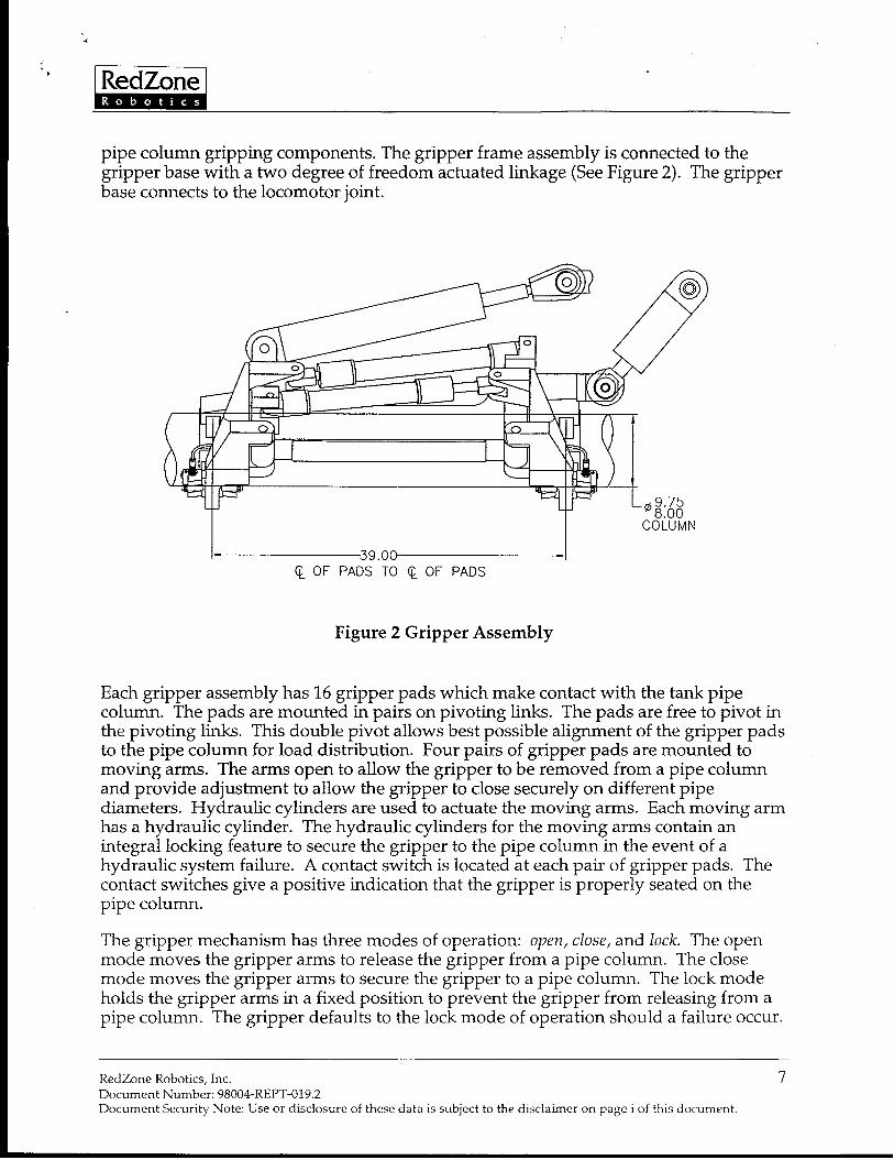
‘Ei!i%i&pipe column gripping components. The gripper frame assembly is connected to thegripper base with a two degree of freedom actuated linkage (See Figure 2). The gripperbase connects to the locomotor joint.
o
—\
(I1_
~39.oo--lQ OF PADS TO Q OF PADS
Figure 2 Gripper Assembly
Each gripper assembly has 16 gripper pads which make contact with the tank pipecolumn. The pads are mounted in pairs on pivoting links. The pads are free to pivot inthe pivoting links. This double pivot allows best possible alignment of the gripper padsto the pipe column for load distribution. Four pairs of gripper pads are mounted tomoving arms. The arms open to allow the gripper to be removed from a pipe columnand provide adjustment to allow the gripper to close securely on different pipediameters. Hydraulic cylinders are used to actuate the moving arms. Each moving armhas a hydraulic cylinder. The hydraulic cylinders for the moving arms contain anintegral locking feature to secure the gripper to the pipe column in the event of ahydraulic system failure. A contact switch is located at each pair of gripper pads. Thecontact switches give a positive indication that the gripper is properly seated on thepipe column.
The gripper mechanism has three modes of operation: open, close, and lock. The openmode moves the gripper arms to release the gripper from a pipe column. The closemode moves the gripper arms to secure the gripper to a pipe column. The lock modeholds the gripper arms in a fixed position to prevent the gripper from releasing from apipe column. The gripper defaults to the lock mode of operation should a failure occur.
RedZone Robotics, Inc. 7Document Number: 98004-REPT-019.2Document Security Note: Use or disclosure of these data is subject to the disclaimer on page i of this document.
The gripper mechanism is designed to minimize the contact stresses induced in the tankpipe columns while providing sufficient rigidity for locomotor and dexterousmanipulator operations.
The grippers are fabricated from aluminum for weight reduction. Electroless nickelplating overcoated with epoxy paint is used for corrosion protection of the aluminum.
Vertical Translation Mechanism
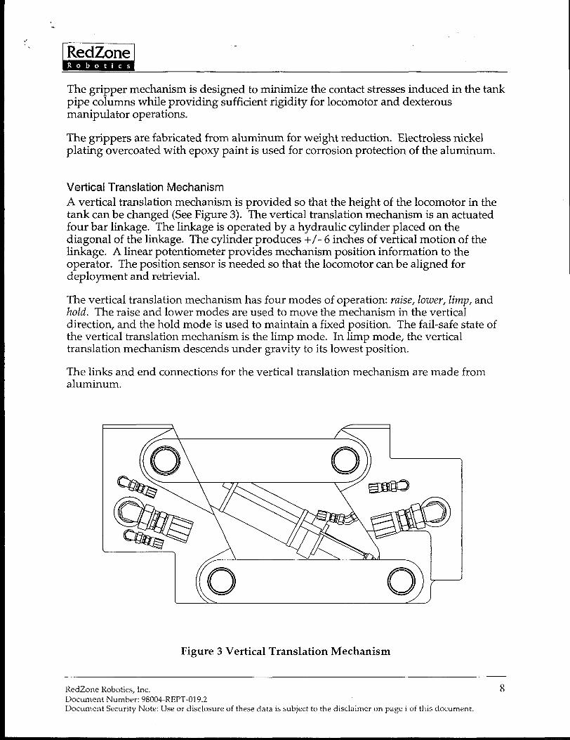
A vertical translation mechanism is provided so that the height of the locomotor in thetank can be changed (See Figure 3). The vertical translation mechanism is an actuatedfour bar linkage. The linkage is operated by a hydraulic cylinder placed on thediagonal of the linkage. The cylinder produces +/-6 inches of vertical motion of thelinkage. A linear potentiometer provides mechanism position information to theoperator. The position sensor is needed so that the locomotor can be aligned fordeployment and retrieval.
The vertical translation mechanism has four modes of operation: raise, lower, limp, andkold. The raise and lower modes are used to move the mechanism in the verticaldirection, and the hold mode is used to maintain a fixed position. The fail-safe state ofthe vertical translation mechanism is the lim~ mode. In lim~ mode, the verticaltranslation mechanism descends under gravity to its lowest’position.
The links and end connections for the vertical translation mechanismaluminum.
are made from
Figure 3 Vertical Translation Mechanism
RedZone Robotics, Inc. 8Document Number: 98004-REPT-019.2Document Security Note: Use or disclosure of these data is subject to the disclaimer on page i of this document.
&
Link
A link connects two of the locomotor joint rotary actuators on the RTD locomotor. Thelink provides a structural connection between the two actuators. It also provides anattachment point for the tether termination as well as distribution of hydraulic andelectrical circuits. The dexterous manipulator is mounted on the link.
The interior of the link serves as an electrical cable and hydraulic hose passageway. Allhoses and cables on the locomotor are internally routed where possible to preventdamage from contact with tank structure to improve system reliability.
The link is fabricated from aluminum for weight reduction. Electroless nickel platingovercoated with epoxy paint is used for corrosion protection of the aluminum.
The link is designed to minimize the decontamination time for the locomotor. Theexterior surfaces of the link are smooth to prevent contamination buildup, and theinternal chamber of the link is sealed to prevent internal contamination.
RedZone Robotics, Inc. 9Document Number: 98004REPT-019.2Document Security Note: Use or disclosure of these data is subject to the disclaimer on page i of this document.

*
,,. Raza
Joints
Three locomotor johtassemblies areused in&e RTDlocomotor. Eachlocomotorjoirttis a modular assembly containing a hydraulic rotary vane actuator with integralbearings, a hydraulic rotary union, and a position sensor. (See Figure 4) The joint haslow friction to enable a limp fail-safe condition. The integral rotary union passeshydraulic fluid between locomotor links. A through-hole in the rotary union allowselectrical cables to pass through the rotary joint. Each joint contains a resolver forposition sensing. The resolver provides absolute position feedback. Resolvers are usedfor their resistance to interference and degradation by ionizing radiation. Actuatorspecifications are given in Table 2.
Figure 4 Locomotor Joint
RedZone Robotics, Inc. 10Document Number: 98004-REPT-019.2Document Security Note Use or disclosure of these data is subject to the disclaimer on page i of this document.

,&
“ -ActuatorStyle I SingleVaneType,DoubleShaftConfi~rationHydraulicFluid I ShellTellus32 mineraloilAmbient Temperature O°Fto 100‘FEnvironment Caustic,pH 9-12, maybe pH 4-6 for short period
Actuator/Swivel Friction 250 ft-lbf maximum
Cross Vane Leakage 0.1 gpm maximum at suggested operating pressure
Swivel Leakage Rate 0.01 gpm to Tank line at 3000 psiNo leakage between other passages or to external
Radiation Peak Dose Rate of 500 rad/hr
Total Cumulative Dose of 107 rad
Rotation Travel 230 deg minimum
Rotational Speed 10 deg/sec maximum
Net Output Torque Under Full 21,631 in-lbf minimumLoad
Operating Pressure I 3,000 psi
Moment Load I 150,000 in-lbf
I Axial Load I 2138 lbf I
Table 2 Locomotor Joint Specifications
The locomotor joints are fabricated from 4130 steel with a corrosion protective finish.
Locomotor Hydraulic SystemThe locomotor hydraulic system, in conjunction with control electronics, providescontrolled motion of the locomotor joints, grippers and vertical translation mechanism.Hydraulic fluid is supplied to the locomotor by pressure and return hoses in the tether.Hydraulic fluid is also supplied to the dexterous manipulator.
The locomotor hydraulic system uses radiation hardened servo valves and directionalcontrol valves to operate the hydraulic actuators. The servo valve electronics arelocated outside the tank environment to protect them from radiation exposure.Hydraulic manifolds in the locomotor provide hydraulic power distribution throughoutthe locomotor and mounting locations for the servo and directional control valves.
Additional valves are needed to meet fail-safe requirements, i.e., fail-safe limp of thelocomotor joints and vertical translation mechanism. These valves are also incorporatedin the manifolds.
A multi-passage hydraulic rotary joint is incorporated into the locomotor joint rotaryactuator to pass fluids through the locomotor. This provides a more compact designand eliminates the use of hoses in this high flex area.
RedZone Robotics, Inc. 11Document Number: 98004-REPT-019.2Document Security Note Use or disclosure of these data is subject to the disclaimer on page i of this document.
‘“’ kii%iiiStainless steel tubing and manifold passages are used where possible to minimize theuse of flexible hoses to improve reliability. Figure 5 (attached to the end of this report)shows the hydraulic schematic of the locomotor.
Video System
Five black and white camera and light assemblies are used on the locomotor. Twocameras are mounted on each gripper to assist the operator in positioning the gripperon the pipe column. One camera is mounted on the dexterous manipulator to provide aview of the manipulator work area. This camera can also be used to provide someoverview capability.
All of the cameras are based on the Rees R980 camera with a Chalnicon image tube.This camera will operate at a dose rate of 105 rad/hr and survive a total dose of 10s rad.This comfortably exceeds the dose rate and total dose expected for the RTD system.Customized housings are used for all cameras. The cameras and lights are sealed forunderwater use. Mounting of the lights is designed to minimize heat transfer to thecameras.
Lens cleaning is provided by a water/air spray nozzle at the camera. Lens cleaning isinitiated from the Operator Control Station. A separate lens cleaning control isprovided for each camera. A spray of water from the nozzle dislodge waste materialfrom the camera lens. A subsequent air blast removes water droplets. This lenscleaning system has been demonstrated on the HoudiniTM system at ORNL and is veryeffective.
Dexterous ManipulatorThe locomotor is equipped with a dexterous manipulator to perform work in the tank.The dexterous manipulator is mounted to the locomotor link. The locomotor is used asa mobile base for the dexterous manipulator. The dexterous manipulator is controlledfrom the Operator Control Station.
A Schilling Titan III manipulator is used. Specifications for the Titan III manipulator arelisted in Table 3. The payload capacity of the Titan III manipulator is limited to 100 lbfby a pressure regulating valve in the locomotor.
RedZone Robotics, Inc. 12Document Numbe~ 98004-REPT-019.2Document Security Note: Use or disclosure of these data is subject to the disclaimer on page i of this document.

‘* EiEEiilPayload 100 lbf at full reach at 3000 psi
Reach 75.4 inches
Wrist Torque 60 ft-lbf
Jaw Closure Force 1000 lbf
Weight 221 lbf
Operating Pressure 3000 psi maximum
Hydraulic Fluid Shell Tellus 32 or equivalent
Table 3 Titan III Manipulator Specifications
Locomotor Control StrategyTwo locomotor control methods are provided for the operator to move the locomotor inthe tank. The control method will be selected with a switch on the control console. Thecontrol methods are described below.
Joint Control
The simplest method for controlling the motion of the locomotor is independent controlof each joint. A rocker switch is provided for each locomotor joint. Each joint is servocontrolled and will follow the control input. Joint speed will be limited to preventunwanted locomotor dynamics.
Coordinated Joint Motion
With this control method, the rotation of all three joints will be coordinated by thecontrol system to achieve the operator specified movement of the free locomotorgripper. A three degree of freedom joystick will be used to control the position andorientation of the free gripper of the locomotor. The control system will determine therequired motion of the actuators to achieve the desired gripper position and orientation.Joint speed will be limited to prevent unwanted locomotor dynamics.
HPUThe Hydraulic Power Unit (HPU) for the RTD system is an independent systemconnected to the locomotor tether with a 125 foot long heated hydraulic hose bundle. Itis housed in an environmental enclosure with access doors for maintenance. Theenvironmental enclosure contains a skid mounted motor, pump and 60 gallon reservoir,plus two electrical enclosures (power switchgear and signals). External 480 VACpower, switchgear control lines and feedback are connected to the enclosure. The HPUcan be mounted up to 250 feet from the control console.
The motor and pump can continually supply 10 GPM of hydraulic fluid at 3,000 psi. Aseparate cooling and filtration “kidney” loop provides continuous filtration and cooling
RedZone Robotics, Inc. 13DocumentNumber:98004-REPT-019.2DocumentSecurityNote:Useordisclosureofthesedataissubjecttothedisclaimeronpagei ofthisdocument.
‘““Riiiifor 100 % of system capacity up to 100° F ambient temperature. The reservoir is heatedto maintain the reservoir fluid at 40° F minimum at –10° F ambient. The system has anaccumulator and relief valve. The system operates with Shell Tellus 32 hydraulic fluid.
The HPU switchgear enclosure contains the control devices to manage power to theHPU. The main power circuit breaker is manually operated, and can be tripped by aground fault. Motor starters with overcurrent and thermal protection control thehydraulic pump, the kidney pump, cooling fan and reservoir heater. Software controlprevents the motors from starting simultaneously, to avoid excessive inrush currents.All motor starters can be disabled by a redundant, series connected, hardwiredEmergency Stop chain. A break in the electrical chain wiring will also trigger an E-Stopshutdown.
The HPU signal enclosure contains the connection points for feedback signals from theHPU and locomotor to the control console. The sensor signals in the HPU includereservoir temperature, reservoir level, hydraulic supply pressure and two hydraulicfilter clog switches.
The environmental enclosure also contains a pressurized water/air system to clean thelocomotor camera lenses via the tether. Water is pumped down the 250 psi line in thetether. This washes the camera lenses. Air follows down the same line to dry the waterdroplets from the camera lenses. The capacity of this system is 2 GPM of water at 60 psiand 10 SCFM of air at 250 psi.
Control StationThe Operator Control Station is to be located in a WVNS supplied control trailer. TheControl Station consists of the Control Console and the Control Rack. The operatorcontrols the system from the Control Console. The Control Rack is a 19” rack mountenclosure that includes the following equipment: A VME subrack provides the actuatorcontrol CPU, 1/0 modules to interface to the analog and digital signals from thelocomotor and HPU, and hardware interlocks to prevent illegal motion commands tothe locomotor. A camera control unit, video router and quad splitter allow the operatorto select appropriate camera views. Power distribution provides power to the rackequipment, the hydraulic solenoid valves throughout the system, the camera lighting,servo amplifiers and 120 VAC auxiliary loads.
The Control Console consists of two separate working surfaces, the Control Panel andthe Status Panel. The Control Panel contains controls used more frequently to operatethe locomotor. The Status Panel contains controls used less frequently, as well as statusindicators. Three black and white video monitors provide feedback from the locomotorand overview cameras. Any camera can be displayed on any monitor and one of themonitors can display four views simultaneously using a quad splitter. The operatorcan choose anywhere between one camera displayed on all three monitors, and sixseparate views. A touchscreen display provides additional control input and statusinformation, camera mappings, plus interlocking menus and procedures.
RedZone Robotics, Inc. 14DocumentNumber:98004-REPT-019.2DocumentSecurityNote:Useordisclosureofthesedataissubjecttothedisclaimeron page i of this document.

“iiiiimThe Control Panel contains switches, indicators, joysticks and the dexterousmanipulator master arm. These controls allow the operator to do the following:● Raise and lower the vertical translation mechanism.● Select either coordinated joint control or individual joint motion, and select which
joint is being controlled by the joystick in individual joint mode.● Move the three rotary actuators using a joystick. Switches on this joystick provide
deadman safety and tether payout functions.● Select which gripper is to be controlled.● Move the tilt and rotate functions on the selected gripper using another joystick.
Switches on this joystick provide the deadman and gripper open/close functions.Hardware interlocks guarantee that one gripper will not release unless the othergripper is firmly attached to a column. Software interlocks are automatically checkedbefore locomotor or gripper motion.
The Control Panel contains indicators for locomotor motion mode, rotary actuatorselected, vertical translation mechanism position, gripper selected, and gripper contactswitches to make sure each gripper is holding. The dexterous manipulator mastercontrol arm is mounted on an elevated bracket that inverts the master arm. Since theslave arm is mounted inverted to the underside of the locomotor, this providesintuitive master arm kinematic control for the operator.
The Status Panel contains the controls and indicators for the HPU, the dexterousmanipulator master controller unit, and the locomotor cameras. Controls are includedto tu~n the HPU on and off, turn the spray wand for cleaning the tank on and off,control all locomotor camera functions except lights, the Emergency Stop function,to silence the audible alarm when a fault condition occurs. This panel containsindicators for system power, HPU status, hydraulic functions and the spray wandoperational status. The locomotor camera lights are controlled by the touchscreen.
and
RedZone Robotics, Inc. 15DocumentNumber:98004-REFT-019.2DocumentSecurityNote:Useordisclosureofthesedataissubjecttothedisclaimeronpagei ofthisdocument.

*“R!RiiiiResults and Discussion
Current StatusDue to several factors related to West Valley operations it was concluded that thedelivery schedule for the final Tarzan system was not compatible with West Valley’sneeds. In addition, West Valley has been experiencing better recovery than expectedusing the sluicing method currently in practice. Based on these factors, a decision wasmade to stop the Tarzan assembly until a modified statement of work could bedeveloped. Based on lengthy discussions with FETC and West Valley, RedZonesubmitted a change in scope to bring the assembly work to a logical conclusion point.In addition, we are collating all existing documentation for final delivery. Asmanufacture of some parts of the system is not complete, the final package does notrepresent the design in all aspects. In particular, the actuator did not pass thepreliminary testing after several attempts. The changes to the final actuator design havebeen conceived, but due to the cost and time required, we will not be manufacturing afinal actuator to prove the design.
The system has been assembled to the extent possible to reduce the total number ofdiscrete parts which must be stored. With respect to each major subsystem, this meansthe following
Locomotor – With the exception of the three rotary actuators, all of the locomotorpurchased and fabricated parts were received. The appropriate parts were nickelplated. The parts were assembled into the major subsystems, namely the two grippers,the two wrists, the link, and the vertical translator. The subsystems were assembledtogether to the extent possible without the three rotary actuators. No hydraulicplumbing or electrical wiring was done on the locomotor subassemblies.
Dexterous Manipulator – The Schilling dexterous manipulator was received from themanufacturer and tested. It was shipped separately, at West Valley’s request. TheSchilling Master Controller was installed in the control console, but was removed andshipped with the manipulator.
Cameras – The two dual gripper cameras and the manipulator wrist camera werereceived from the manufacturer. The cameras were tested by the manufacturer anddemonstrated at RedZone. The cameras have not been installed on the locomotorsubassemblies.
Tether Reel – The tether reel was received from the manufacturer and inspected. Nofurther assembly was done on the tether reel since integration had not progressed thatfar when the project scope was modified.
RedZone Robotics, Inc. 16Document Number: 98004-REPT-019.2Document Security Note: Use or disclosure of these data is subject to the disclaimer on page i of this document.

‘-’‘ RzilHPU – The Hydraulic Power Unit was received complete from the manufacturer andinstalled in its environmental enclosure. The FII?U was tested by the manufacturerprior to shipment. This item is complete except for a minor red tag item (an extra sightglass was installed by the manufacturer).
Control Console – The control console furniture, panels and panel components werereceived and assembled. The Schilling manipulator Master Controller was installedinto the control panel. The camera controls were also installed. The control panel waswired. The Control Rack was assembled and wired, including power supplies,electronics chassis with computer, memory and 1/0 cards and video equipment. TheSchilling Master Controller was removed so that it could be shipped with the Schillingarm. The control console is complete with the exception of the Schilling MasterController.
Bulkhead Panel – The bulkhead panel was fabricated and the connectors, fittings,power supplies and other electronics were assembled onto it. This item was completedto the level of integration accomplished at the time the project scope was modified.
Interconnect Cables – The interconnect cables were received from the manufacturer,inspected, and sent back to the manufacturer for some rework. The reworked cableswere received and inspected. They are complete, but have not been integrated into thesystem.
There are additional smaller parts that have not been installed because the integrationhad not proceeded to that point at the time the contract was modified. The finaldisposition of all the parts is still open, but in the event that the system is required atsome point downstream, the design will be available and the project could be revived.Based on this current status, it is difficult to discuss any concrete results since the finalsystem is not operational. The following chapter does discuss some of the lessonslearned through the development effort.
RedZone Robotics, Inc. 17DocumentNumber:98004-REPT-019.2DocumentSecurityNoteUseordisclosureofthesedataissubjecttothedisclaimeronpagei ofthisdocument.

Conclusions
Lessons LearnedThrough the course of the Tarzan development RedZone worked closely with thetechnical experts at West Valley to determine the needs and requirements for thesystem. The technical communication was very good, but sometimes RedZone’s andWVNS’S QA and documentation requirements were not in unison. The followingsection details some observations and conclusions related to the Tarzan development.
The design of a rotary actuator to meet the requirements of the Tarzan system turnedout to be more challenging than we had expected. Unfortunately, the initial vendorselection was deemed inadequate upon evaluation of their initial prototype. This addedsignificant time and cost to the project. Subsequently, we did proceed with a vendorcapable of building an actuator to meet our specifications, but several iterations wererequired to generate a final design. Thus the actuator design trailed the rest of theproject creating a significant technical risk to program success.
In addition, we experienced significant difficulty in implementing West Valley’s QAand documentation requirements. Through the various stages of the project, WVNSidentified several areas where West Valley expectations for the level of documentationwere not being met by RedZone’s standard practice. Initially, RedZone was notcognizant as to the extent of documentation (such as Certificates of Conformance,Certified Material Testing Reports, and Instrument Calibration Certificates) that wasrequired from vendors. Later, verification that the required documentation wasshipped with the parts was not done on a consistent basis. In several cases this forcedRedZone to travel back to recapture documentation not initially requested or received.This added significant effort that could have been avoided had we understood therequirements up front. In the end, West Valley provided an on-site liaison to assist usin preparing the documentation requirements to meet West Valley’s needs. This provedto be a good solution to preventing any mismatch in expectations. Eventually, detailedprocurement specifications were written for major subsystems that defined the criticalrequirements for the subsystem and requested documentation that the requirementswere met. These subsystems included the HPU, Rotary Actuator, Tether Reel, SlipRing, Gripper Cylinder, Gripper Camera, Tether Assembly, VTM Feedback Device,Interconnect Cabling, Gripper Pads, Nickel Plating and Painting.
Finally, RedZone was not fully sensitive to the importance of maintaining timelyschedule and budget information. As the project moved forward RedZone brought onnew staff members who were not as experienced in driving the project to keymilestones and management oversight did not identify the difficulties in a timelyfashion. As a result, the project schedule and budget were affected adversely. We haveworked to correct those problems and have now adopted a different structure which
RedZone Robotics, Inc. 18DocumentNumber:98004-REPT-019.2DocumentSecurityNoteUseordisclosureofthesedataissubjecttothedisclaimeronpagei ofthisdocument.
-#-
allows us to track schedule and budget on all of our projects in a more effective manner.The following items are part of this new structure. A schedule was developed based ona finely detailed Work Breakdown Structure, and a budget was tied to that schedule.The budget and schedule were monitored weekly, and variance reports were issued.The schedule was reviewed at the weekly conference calls and off schedule items wereidentified and discussed for faster resolution. New procedures were implemented inhouse dealing with the inspection and receipt of items to assure that requesteddocumentation was included with the item. Inspection and documentation forpurchased items was emphasized in recurrent QA training for all employees.
RedZone Robotics, Inc. 19DocumentNumber:98004-REPT-019.2DocumentSecurityNote:Useordisclosureofthesedataissubjecttothedisclaimeronpagei ofthisdocument.

‘) ‘,
X3 .3
SAE–:2
SAE–4 c’ SAE–4
X3
ITSAE–~ c’ SAE–4 f“C2~..—!:.
p
21
cl C2
SAE -
SAE-VT
LENS GRIPPER GRIPPER GRIPPER ROTARY ACTUATOR
Cl FANIN12 CONTROI LOCK TILT CONTROL
—..—1
CONTROL CONTROL
X3 X3
h , H+
r’vlFSAE–? SAE–4 c’ SAE–4
SAE–4
! r“”--r””-””---- “--”-- ‘--””-”--”---”-””-”--rl
SAE–4 SAE–4r“” GRIP C2 GRIP c1 LOCK
+ ~ % 2~ iiit r~ASAE–4 ~
lN -;LENS 1
cl..-
C2
SAE–4 i ‘E”’.,>N,-
,,
m-t E4
PI
R ‘“--”i.. -
I I l%
‘i AAL....:5..–..–..–.–..–.–..–..–..–..–..–.._.._
R C2
SAE–i’ SAE–4 Q
SA
–..54.
LENS GRIPPER GRIPPERCLEANING CONTROL LOCK
1A-..—.
TILT Cl TILT C2
4!!, ~
m
i--–--–--–--–--–--–--–-
~ R! sAE–4 I WRIST J1 1
WASH lN~ sAE–4 1LC
SAE–4!~--–-* --–--–--–--–w--–--k--–--–--J L.. —..—..—..—..—.._.._.
GRIPPERTILT
CONTROL CONT
3
& lvlOOG, 30 SERIES, SE f7V0 VALVE
.(&&) HYDRAFORCE, SV08-26, SOL. VALVE, 2-WAY
‘) A SPARTAN SCIENTIFIC, 3800 SERIES, SOL. VALVE
~ SUN HYDRAULICS, PBDB-LAN, PRESSURE
REDUCING VALVE
~ HYDRAFORCE, SV08-30, SOL VALVE, 3-WAY
~ SUN HYDRAULICS, PPDB-LAN, PRESSUREREDUCING/RELIEVING VALVE
ROTARY ACTUATORCONTROL
UI
REMOVE ALL BU
ALL SHARP EDG
CHAMFER 1ST T
EXTERNAL THRE/
C’SK 1ST THREI
HOLES 9(Y TO 1
DIMENSIONING A
DASH NEXT ASSY QTYIN ACCORDANCE
NO Y14.5M–1994.
DRAWINGTH(RO ANGLE PR
?EFERENCE @%

+
b ~’.,... REVISIONS
REV DESCRIPTION DATE APPROVTETHER
CONNECTION
J=#-SAE–4 Q.C2~.. —.. —c.’.
LENSCLEAN!NG
SAE–4..—..—..—..—..—..—..—..—
1c1 ;Al$J2
21
SAE–4
SAE–4+7._ SAE–4w C2 1
I
I
I
I
I
I
1
vc1 C2
SAE–4 SAE–4
L--J
A&
&l2 &1
1 C2
R
--i
!-l-PR
ISAE–4
I Ri
sAE–8 i ~
I
m’7 ‘
j SAE–4
SAE–10~ , /“& ‘:
T “----”-”- ‘“”:”; ‘-- ““- ‘--”------”-””-””-”-” ‘-””J
7
c1 ‘ -iLOCOMOTOR
7SAE–4
!
LINK C2
llP!
kAE-4P P ~sAE–4
isAE–4R R I R
LC LC LC ‘sAE–4
.._.._..l..l.._.._.._.._.._.._.._.._.._..~---..J I‘IPPER 1 HYDRAULIC ROTARY
SWIVELSAE–4 SAE–4 VERTICAL HYDRAULIC
TRANSLATION SWIVELCONTROL
ITATEINTROL
ACTUATOR 2
CONTROL
wc1 C2
4 SAE–4
II
TO MANIPULATOR i
I
FIGURE 5
HYDRAULIC SCHEMATIC
“-””----”l-!—..
P
ITR
I: SAE–4
i SAF–4
—
1 ! sAE_4J
IL.. _..;
GRIPPER 1 HYDRAULICROTATE SWIVELCONTROL
:SS OTHERWISE SPECIFIED
=-N. 412-765-;064RFIT70NE RJHTYJVW52.4,; AND BREAK
TO .015 MAX.DO NOT SCALE DRAWING
:AD ON
F
ALL DIMENSIONS ARE IN INCHES
4s. TOLERANCES: Xxx +.020
)F TAPPED X.xxx *.,,5
3R DIA ANGLES *0.50”
TOLERANCING
rH ASME
d
SURFACE TEXT”RE 125
CHKR:
LOCOMOTORENGR: 03/13/98
APP HYDRAULIC SCHEMATIC~pp: CAGE COOE
~T”JN TREATMENT. MATERIAL: OK896 ‘; 98004017’ ~
+ SCALE I :8 WEIGHT: SHEET I OF 1