Embed Size (px)
Citation preview
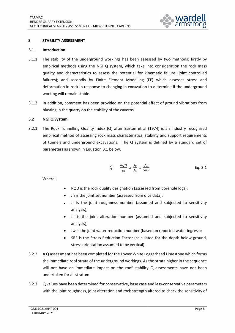
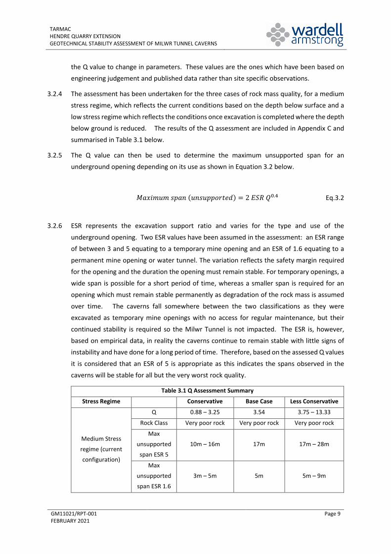
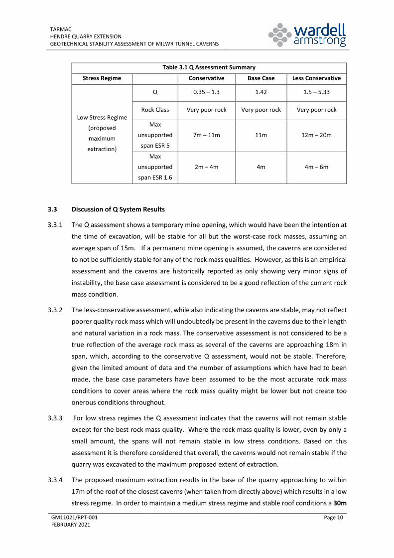
TARMAC
HENDRE QUARRY EXTENSION
GEOTECHNICAL STABILITY ASSESSMENT OF MILWR TUNNEL CAVERNS
FEBRUARY 2021
Wardell Armstrong 41-50 Futura Park, Aspinall Way, Middlebrook, Bolton, BL6 6SU Telephone: +44 (0)1204 227 227 www.wardell-armstrong.com
Wardell Armstrong is the trading name of Wardell Armstrong LLP, Registered in England No. OC307138.
Registered office: Sir Henry Doulton House, Forge Lane, Etruria, Stoke-on-Trent, ST1 5BD, United Kingdom
UK Offices: Stoke-on-Trent, Birmingham, Bolton, Cardiff, Carlisle, Edinburgh, Glasgow, Leeds, London, Newcastle upon Tyne and Truro. International Offices: Almaty and Moscow
ENERGY AND CLIMATE CHANGE ENVIRONMENT AND SUSTAINABILITY
INFRASTRUCTURE AND UTILITIES LAND AND PROPERTY
MINING AND MINERAL PROCESSING MINERAL ESTATES
WASTE RESOURCE MANAGEMENT
DATE ISSUED: 16 February 2021 JOB NUMBER: GM11021
REPORT NUMBER: R01 VERSION:
STATUS:
V0.2
Final
TARMAC
HENDRE QUARRY EXTENSION
GEOTECHNICAL STABILITY ASSESSMENT OF MILWR TUNNEL CAVERNS
FEBRUARY 2021
PREPARED BY:
Naomi Lee Associate Director
Allan Sim Technical Director
REVIEWED BY:
Martin Downing Associate Director
APPROVED BY:
Gavin Campbell Service Director
This report has been prepared by Wardell Armstrong LLP with all reasonable skill, care and diligence, within the terms of the Contract with the Client. The report is confidential to the Client and Wardell Armstrong LLP
accepts no responsibility of whatever nature to third parties to whom this report may be made known. No part of this document may be reproduced without the prior written approval of Wardell Armstrong LLP.
TARMAC HENDRE QUARRY EXTENSION GEOTECHNICAL STABILITY ASSESSMENT OF MILWR TUNNEL CAVERNS
GM11021/FINAL FEBRUARY 2021
CONTENTS
1 INTRODUCTION .................................................................................................................. 1
2 MODEL PARAMETERS ........................................................................................................ 5
3 STABILITY ASSESSMENT ..................................................................................................... 8
4 CONCLUSIONS .................................................................................................................. 14
FIGURES
Figure 1.1 Photograph of limestone caverns Figure 3.1 FE model of current ground conditions
Figure.1 FE model of revised maximum extraction (30m vertical standoff) Figure 3.3 FE model of backfilled quarry
APPENDICES
Appendix A Geological Borehole Logs Appendix B Dips analysis
Appendix C Q Assessment (all strata) Appendix D Rock Properties Assessment Appendix E Geostudios FE modelling outputs
Appendix F Photographs of the limestone caverns (Grosvenor Caving Club 2019 and 2020)
DRAWINGS TITLE
GM11021 - 001 Site Location GM11021 - 002 Site Layout
GM11021 – 003 Model Cross Section
TARMAC HENDRE QUARRY EXTENSION GEOTECHNICAL STABILITY ASSESSMENT OF MILWR TUNNEL CAVERNS
GM11021/RPT-001 FEBRUARY 2021
Page 1
1 INTRODUCTION
1.1 Scope of works
1.1.1 This report has been prepared further to instructions from Mr John Sergeant, Geological Manager – Central, for Tarmac following a proposal from Wardell Armstrong (WA) dated 31st January 2020.
1.1.2 Hendre Quarry is owned and operated by Tarmac and is located approximately 4km north-west of Mold, Flintshire. The site location is shown on Drawing No GM11021-001. The quarry
extracts limestone for aggregate and Tarmac are in the process of applying for planning permission to extend the existing quarry eastwards.
1.1.3 The Milwr Tunnel is a 16km long former mine drainage tunnel that runs from the coast at Bagillt to Loggerheads, near Mold. The tunnel passes approximately 300m to the east of the
current extent of the quarry. Several historic limestone mine workings or caverns, known as ‘the Quarry’, driven off the tunnel, extend to within approximately 17m below the proposed
quarry expansion.
1.1.4 Wardell Armstrong has been appointed to undertake a geotechnical stability assessment of
the proposed extension on the underlying mine workings. A draft stability assessment report was submitted to Tarmac on 14 October 2020 and was discussed with Tarmac on 21 January
2021. This final report summarises the parameters used, the models created, and the results of the stability assessments undertaken.
1.2 Background
1.2.1 The Milwr Tunnel was driven between the late 1800’s and the 1940’s to drain the former lead mines of the Halkyn Mountain area. The tunnel is approximately 300m to the east of the
current quarry at an elevation of approximately 21m AOD. The tunnel interconnects a large and complex system of former mine workings and natural conduits and, as such, it is the single
most important controlling factor in the hydrogeology of the area. The tunnel has a continuous flow of water from both deep groundwater and surface sources, with a mean
annual flow in the order of 1m3/s.
1.2.2 Mining of lead ore and limestone ceased in 1977 and since then the tunnel has been used as
a raw water supply with abstraction taking place at the Bagillt portal. United Utilities plc (UU) currently have the right to abstract water from the tunnel and, until recently, they extracted
water from it to supply a non-potable water source for local industry. UU also have responsibilities to ensure an uninterrupted flow of water through the tunnel, and rights to
inspect and carry out any remedial works necessary to ensure the integrity of the tunnel.
1.2.3 As part of this obligation, since 2010 UU have commissioned inspections of the tunnel between Olwyn Goch Shaft (adjacent to Hendre Quarry) and the portal at Bagillt. These
TARMAC HENDRE QUARRY EXTENSION GEOTECHNICAL STABILITY ASSESSMENT OF MILWR TUNNEL CAVERNS
GM11021/RPT-001 FEBRUARY 2021
Page 2
inspections have subsequently led to significant repair works along sections of the tunnel to maintain its integrity and ensure the continued flow of water along it. It should be noted,
however, that those inspections did not include the limestone caverns.
1.2.4 In accordance with The Mines Regulations 2014, the tunnel is classed as a “mine” and, as such,
the requirements of the regulations are applicable at any time when there are persons at work below ground (Regulation 3). The “mine owner” in accordance with the regulations is the Halkyn District Mines Drainage Co. Ltd (HDMDC), a fully owned subsidiary of United Utilities
plc. During the inspections and repair works undertaken in the tunnel, HDMDC have appointed Wardell Armstrong LLP as the “mine operator”, responsible for the management
of the health and safety of the mine.
1.2.5 In its middle and upstream sections, the tunnel passes through limestone strata. In the vicinity
of Olwyn Goch Shaft, the limestone is of particular high purity and was worked underground from the tunnel and shaft in an extensive series of caverns from the early 1940s until 1967.
The workings form long galleries or drives separated by pillars of limestone. The drives range in size from 12m to 18m wide, with the majority of the caverns being 15m wide. The caverns
are shown on mine abandonment plans, showing the recorded areal extent of the caverns and occasional elevations of the roof and floor.
1.2.6 The roof strata of the caverns follow a geological marker horizon which dips toward the ENE and, as such, the caverns tend to increase in height to the west. The height of the caverns is
recorded to vary from approximately 15m up to a maximum height of approximately 47m at the western end closest to Hendre Quarry. Some of the caverns have an irregular ‘keyhole’ profile in cross section with the lower half narrower than the upper section, with a narrow
bench or shoulder observed. However, this is not a uniform profile in all the caverns.
1.2.7 Tarmac propose to expand and deepen the quarry eastwards working the Upper and Lower
Limestone units by blasting a benched profile. The extension would be undertaken in six general phases with Phase 5 (to a depth of 72m AOD) and Phase 6 (to a depth of 57m AOD)
being the closest to the underground caverns. Once extraction is completed the quarry will be partially backfilled. The proposed extent of the quarry extension and backfilling relative to
the location of the underground caverns is shown on Drawing No GM11021-002.
1.2.8 It is considered that any significant instability caused in the limestone caverns by the adjacent
quarrying could have knock-on effect on the stability of the Milwr Tunnel, which could result in a blockage to the free flow of water. This would not only interrupt the supply to any
abstractions in the future could also result in significant changes to the hydrogeology of the area with the potential for major geohazards occurring. In addition, any instability could
significantly affect the geotechnical stability of the quarry itself and of the adjacent land.
TARMAC HENDRE QUARRY EXTENSION GEOTECHNICAL STABILITY ASSESSMENT OF MILWR TUNNEL CAVERNS
GM11021/RPT-001 FEBRUARY 2021
Page 3
1.3 Data Sources
1.3.1 The assessment has been based on data provided by Tarmac, published geological and
geotechnical data, engineering experience of similar rock types and WA experience gained in working on remediation and stabilisation measures of the Milwr Tunnel. The supplied data
incudes:
• Mine abandonment plans (refs. AB166 and AB167);
• Exploration drilling borehole logs H72 1/90 – 18/90 (March 1990) and H72 1/66 – 8/66
(August 1966) - geological logs only;
• Exploration drilling borehole logs (November 2002): H72 A/01 – I/01;
• Geological interpretation of 2002 exploration drilling;
• Geological borehole logs H72/2016/ BH1 – BH5;
• LSS models of Hendre Quarry in current and proposed extension configurations (prepared
by Tarmac)
• Surpac model of underground caverns (prepared by Tarmac);
• Eastern Extension Backfill phases 1- 6 LSS models (prepared by Tarmac);
• Discontinuity summary data;
• Hendre Quarry Stereonets of Hendre Quarry final slope profile;
• Report on Underground Mineworkings at Hendre Quarry, Flintshire by Matthews & Sons.
Dated 5th December 2003;
• Article by W.J. Houston “Limestone mining at Halkyn”.
1.3.2 It should be noted that the provided geological logs do not appear to have been logged to ESN BS standards but rather an internal Tarmac logging standard. Furthermore, the boreholes have only been geological logged and not geotechnically logged.
1.3.3 Of the borehole logs provided only boreholes H72/F/01, H72/G/01, H72/I/01, H72/2016/BH1, H72/2016/BH2, H72/2016/BH3, H72/2016/BH4 and H72/2016/BH5 were in the assessment
area. As would be expected of exploration boreholes they do not progress significantly below the base of the proposed quarry and as such do not extent significantly into the Lower White
Limestone strata. The parameters used in the analysis have therefore been projected from the strata above the workings. The borehole positions are shown on Drawing No GM11021-
002.
1.3.4 The geological logs used in the assessment are included in Appendix A for completeness.
1.3.5 Due to restrictions relating to the COVID 19 pandemic and other health and safety considerations, it has not been possible to access the underground caverns to confirm their
current condition or undertake any geotechnical mapping. During late 2019 and early 2020, visits to the caverns were, however, made by members of the Grosvenor Caving Club.
TARMAC HENDRE QUARRY EXTENSION GEOTECHNICAL STABILITY ASSESSMENT OF MILWR TUNNEL CAVERNS
GM11021/RPT-001 FEBRUARY 2021
Page 4
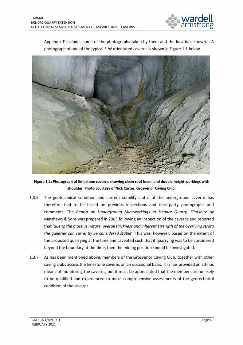
Appendix F includes some of the photographs taken by them and the locations shown. A photograph of one of the typical E-W orientated caverns is shown in Figure 1.1 below.
Figure 1.1: Photograph of limestone caverns showing clean roof beam and double height workings with
shoulder. Photo courtesy of Nick Carter, Grosvenor Caving Club.
1.3.6 The geotechnical condition and current stability status of the underground caverns has therefore had to be based on previous inspections and third-party photographs and
comments. The Report on Underground Mineworkings at Hendre Quarry, Flintshire by Matthews & Sons was prepared in 2003 following an inspection of the caverns and reported
that ‘due to the massive nature, overall thickness and inherent strength of the overlying strata the galleries can currently be considered stable’. This was, however, based on the extent of the proposed quarrying at the time and caveated such that if quarrying was to be considered
beyond the boundary at the time, then the mining position should be investigated.
1.3.7 As has been mentioned above, members of the Grosvenor Caving Club, together with other
caving clubs access the limestone caverns on an occasional basis. This has provided an ad-hoc means of monitoring the caverns, but it must be appreciated that the members are unlikely
to be qualified and experienced to make comprehensive assessments of the geotechnical condition of the caverns.
TARMAC HENDRE QUARRY EXTENSION GEOTECHNICAL STABILITY ASSESSMENT OF MILWR TUNNEL CAVERNS
GM11021/RPT-001 FEBRUARY 2021
Page 5
2 MODEL PARAMETERS
2.1 Geology
2.1.1 The superficial geological in the area is characterised by topsoil overlying firm silts and clays with some sand and gravel.
2.1.2 The solid geology of the area is characterised by the limestones and mudstones of the Cefn
Mawr Group which overly the Loggerheads Limestones which are subdivided into the Upper Grey Limestones, the Lower Grey Limestones, the Upper White Limestones and the Lower
White Limestones. The Upper and Lower Grey Limestones are separated by a clear marker horizon of the Main Mudstone while the Upper and Lower White limestones are demarked by
an unnamed thin mudstone band. The stratigraphic sequence is summarised below, and a typical cross section is shown on Drawing No GM11021 – 003.
• Overburden: firm silts and clays with some sand and gravel.
• Cefn Mawr Limestone, dark grey thickly bedded weak to moderately strong limestones interbedded with weak mudstones. Unit in excess of 48m thick.
• Upper Grey Limestones, (Loggerheads limestone group), grey massively bedded strong limestones with thin mudstones partings on bedding planes. Unit
approximately 19m thick.
• Main Mudstone (Loggerheads limestone group), grey green weak laminated
mudstone. Unit 2.5m – 3.7m thick.
• Lower Grey Limestones (Loggerheads limestone group), grey massively bedded strong limestones, interbedded with thin mudstone partings on bedding planes. Unit 30m -
33m thick.
• Upper White Limestones (Loggerheads Limestones group) light grey cream, massively
bedded strong limestone with interbedded clay horizons (0.5m thick) at 7m – 17m intervals. Unit 32m thick. The base of the quarry terminates in this unit.
• Lower White Limestones (Loggerhead Limestones group) White light grey massively bedded limestones with occasional clay bands. Unit 58m thick. The underground mine workings are located within this unit.
2.2 Geotechnical
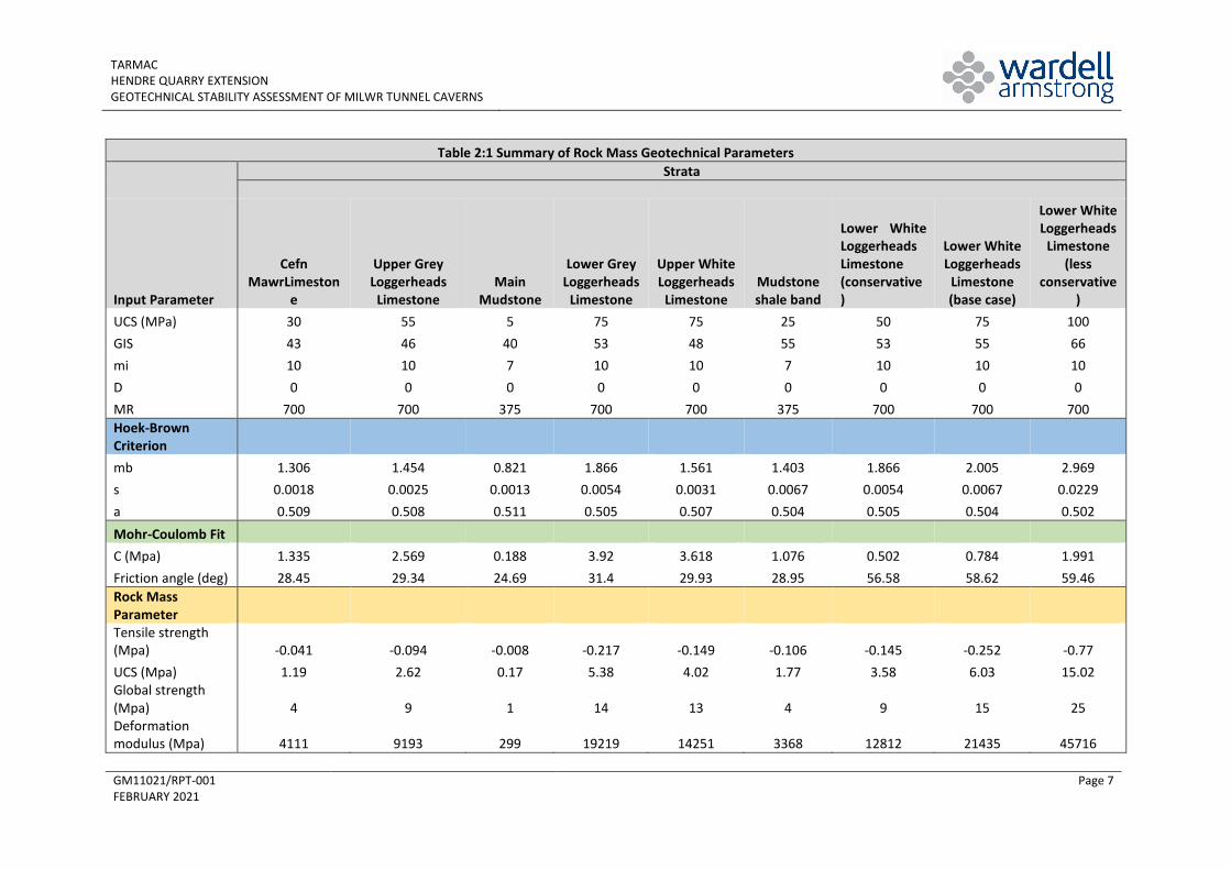
2.2.1 The rock mass properties have been based on the borehole logs, inspection of site
photographs, satellite imagery and the 2003 report on underground mine workings. General rock mass classification using Geological Strength Index (GSI) has been assessed for each rock
type as summarised in Table 2.1 below.
2.2.2 Dips data obtained as part of the routine geotechnical inspection of the quarry has been
processed to determine the number and orientation of the dominant joint sets and bedding, the assessment in included as Appendix B. It should be noted that this data relates to the
TARMAC HENDRE QUARRY EXTENSION GEOTECHNICAL STABILITY ASSESSMENT OF MILWR TUNNEL CAVERNS
GM11021/RPT-001 FEBRUARY 2021
Page 6
exposed faces and not the Lower White Limestones of the underground workings and only include joint dip and dip direction data and not joint condition data. The borehole logs have
RQD measurement with no further geotechnical data.
2.2.3 Analysis of the dip data indicates the rock mass within the quarry is characterised by three
joint sets plus bedding. This configuration gives rise to the sugar cube structure observed in the quarry faces. This joint configuration is assumed for the full stratigraphic column.
2.2.4 The joints have assumed to be rough, irregular planar or smooth planar for a conservative
assessment. Based on the borehole log descriptions the joints have been assumed to be slightly altered with non-softening sandy particles or silty or sandy-clay coatings in the most
conservative assessment.
2.2.5 Based on the Matthews & Son report on the underground workings from 2003, which reports
water ingress along localised joints, a water ingress of medium inflow with occasional outwash of joint filling to a dry excavation has been assumed.
2.2.6 The rock strength properties have been based on the general descriptions in the borehole logs, although these do not generally refer to the strength of the rock type and published data.
The rock strength for each rock type is summarised in Table 2.1
2.2.7 The GSI, rock strength and standard rock constants for each rock type have been input in to
the RocScience software RocLab to determine the, tensile strength, rock mass global strength and deformation modulus. The parameters used in the modelling are summarised in Table 2.1
below.
TARMAC HENDRE QUARRY EXTENSION GEOTECHNICAL STABILITY ASSESSMENT OF MILWR TUNNEL CAVERNS
GM11021/RPT-001 FEBRUARY 2021
Page 7
Table 2:1 Summary of Rock Mass Geotechnical Parameters
Strata
Input Parameter
Cefn MawrLimeston
e
Upper Grey Loggerheads
Limestone Main
Mudstone
Lower Grey Loggerheads
Limestone
Upper White Loggerheads
Limestone Mudstone shale band
Lower White Loggerheads Limestone (conservative)
Lower White Loggerheads
Limestone (base case)
Lower White Loggerheads
Limestone (less
conservative)
UCS (MPa) 30 55 5 75 75 25 50 75 100 GIS 43 46 40 53 48 55 53 55 66 mi 10 10 7 10 10 7 10 10 10 D 0 0 0 0 0 0 0 0 0 MR 700 700 375 700 700 375 700 700 700 Hoek-Brown Criterion mb 1.306 1.454 0.821 1.866 1.561 1.403 1.866 2.005 2.969 s 0.0018 0.0025 0.0013 0.0054 0.0031 0.0067 0.0054 0.0067 0.0229 a 0.509 0.508 0.511 0.505 0.507 0.504 0.505 0.504 0.502 Mohr-Coulomb Fit C (Mpa) 1.335 2.569 0.188 3.92 3.618 1.076 0.502 0.784 1.991 Friction angle (deg) 28.45 29.34 24.69 31.4 29.93 28.95 56.58 58.62 59.46 Rock Mass Parameter Tensile strength (Mpa) -0.041 -0.094 -0.008 -0.217 -0.149 -0.106 -0.145 -0.252 -0.77 UCS (Mpa) 1.19 2.62 0.17 5.38 4.02 1.77 3.58 6.03 15.02 Global strength (Mpa) 4 9 1 14 13 4 9 15 25 Deformation modulus (Mpa) 4111 9193 299 19219 14251 3368 12812 21435 45716
TARMAC HENDRE QUARRY EXTENSION GEOTECHNICAL STABILITY ASSESSMENT OF MILWR TUNNEL CAVERNS
GM11021/RPT-001 FEBRUARY 2021
Page 8
3 STABILITY ASSESSMENT
3.1 Introduction
3.1.1 The stability of the underground workings has been assessed by two methods: firstly by empirical methods using the NGI Q system, which take into consideration the rock mass quality and characteristics to assess the potential for kinematic failure (joint controlled
failures); and secondly by Finite Element Modelling (FE) which assesses stress and deformation in rock in response to changing in excavation to determine if the underground
working will remain stable.
3.1.2 In addition, comment has been provided on the potential effect of ground vibrations from
blasting in the quarry on the stability of the caverns.
3.2 NGI Q System
3.2.1 The Rock Tunnelling Quality Index (Q) after Barton et al (1974) is an industry recognised empirical method of assessing rock mass characteristics, stability and support requirements
of tunnels and underground excavations. The Q system is defined by a standard set of parameters as shown in Equation 3.1 below.
𝑄𝑄 = 𝑅𝑅𝑅𝑅𝑅𝑅𝐽𝐽𝑛𝑛
𝑥𝑥 𝐽𝐽𝑟𝑟𝐽𝐽𝑎𝑎
𝑥𝑥 𝐽𝐽𝑤𝑤𝑆𝑆𝑅𝑅𝑆𝑆
Eq. 3.1
Where:
• RQD is the rock quality designation (assessed from borehole logs);
• Jn is the joint set number (assessed from dips data);
• Jr is the joint roughness number (assumed and subjected to sensitivity analysis);
• Ja is the joint alteration number (assumed and subjected to sensitivity analysis);
• Jw is the joint water reduction number (based on reported water ingress);
• SRF is the Stress Reduction Factor (calculated for the depth below ground, stress orientation assumed to be vertical).
3.2.2 A Q assessment has been completed for the Lower White Loggerhead Limestone which forms
the immediate roof strata of the underground workings. As the strata higher in the sequence will not have an immediate impact on the roof stability Q assessments have not been
undertaken for all stratum.
3.2.3 Q values have been determined for conservative, base case and less-conservative parameters
with the joint roughness, joint alteration and rock strength altered to check the sensitivity of
TARMAC HENDRE QUARRY EXTENSION GEOTECHNICAL STABILITY ASSESSMENT OF MILWR TUNNEL CAVERNS
GM11021/RPT-001 FEBRUARY 2021
Page 9
the Q value to change in parameters. These values are the ones which have been based on engineering judgement and published data rather than site specific observations.
3.2.4 The assessment has been undertaken for the three cases of rock mass quality, for a medium stress regime, which reflects the current conditions based on the depth below surface and a
low stress regime which reflects the conditions once excavation is completed where the depth below ground is reduced. The results of the Q assessment are included in Appendix C and summarised in Table 3.1 below.
3.2.5 The Q value can then be used to determine the maximum unsupported span for an underground opening depending on its use as shown in Equation 3.2 below.
𝑀𝑀𝑀𝑀𝑥𝑥𝑀𝑀𝑀𝑀𝑀𝑀𝑀𝑀 𝑠𝑠𝑠𝑠𝑀𝑀𝑠𝑠 (𝑀𝑀𝑠𝑠𝑠𝑠𝑀𝑀𝑠𝑠𝑠𝑠𝑢𝑢𝑢𝑢𝑢𝑢𝑢𝑢𝑢𝑢) = 2 𝐸𝐸𝐸𝐸𝐸𝐸 𝑄𝑄0.4 Eq.3.2
3.2.6 ESR represents the excavation support ratio and varies for the type and use of the
underground opening. Two ESR values have been assumed in the assessment: an ESR range of between 3 and 5 equating to a temporary mine opening and an ESR of 1.6 equating to a
permanent mine opening or water tunnel. The variation reflects the safety margin required for the opening and the duration the opening must remain stable. For temporary openings, a
wide span is possible for a short period of time, whereas a smaller span is required for an opening which must remain stable permanently as degradation of the rock mass is assumed
over time. The caverns fall somewhere between the two classifications as they were excavated as temporary mine openings with no access for regular maintenance, but their
continued stability is required so the Milwr Tunnel is not impacted. The ESR is, however, based on empirical data, in reality the caverns continue to remain stable with little signs of instability and have done for a long period of time. Therefore, based on the assessed Q values
it is considered that an ESR of 5 is appropriate as this indicates the spans observed in the caverns will be stable for all but the very worst rock quality.
Table 3.1 Q Assessment Summary
Stress Regime Conservative Base Case Less Conservative
Medium Stress
regime (current
configuration)
Q 0.88 – 3.25 3.54 3.75 – 13.33
Rock Class Very poor rock Very poor rock Very poor rock
Max
unsupported
span ESR 5
10m – 16m 17m 17m – 28m
Max
unsupported
span ESR 1.6
3m – 5m 5m 5m – 9m
TARMAC HENDRE QUARRY EXTENSION GEOTECHNICAL STABILITY ASSESSMENT OF MILWR TUNNEL CAVERNS
GM11021/RPT-001 FEBRUARY 2021
Page 10
Table 3.1 Q Assessment Summary
Stress Regime Conservative Base Case Less Conservative
Low Stress Regime
(proposed
maximum
extraction)
Q 0.35 – 1.3 1.42 1.5 – 5.33
Rock Class Very poor rock Very poor rock Very poor rock
Max
unsupported
span ESR 5
7m – 11m 11m 12m – 20m
Max
unsupported
span ESR 1.6
2m – 4m 4m 4m – 6m
3.3 Discussion of Q System Results
3.3.1 The Q assessment shows a temporary mine opening, which would have been the intention at
the time of excavation, will be stable for all but the worst-case rock masses, assuming an average span of 15m. If a permanent mine opening is assumed, the caverns are considered
to not be sufficiently stable for any of the rock mass qualities. However, as this is an empirical assessment and the caverns are historically reported as only showing very minor signs of
instability, the base case assessment is considered to be a good reflection of the current rock mass condition.
3.3.2 The less-conservative assessment, while also indicating the caverns are stable, may not reflect poorer quality rock mass which will undoubtedly be present in the caverns due to their length
and natural variation in a rock mass. The conservative assessment is not considered to be a true reflection of the average rock mass as several of the caverns are approaching 18m in
span, which, according to the conservative Q assessment, would not be stable. Therefore, given the limited amount of data and the number of assumptions which have had to been made, the base case parameters have been assumed to be the most accurate rock mass
conditions to cover areas where the rock mass quality might be lower but not create too onerous conditions throughout.
3.3.3 For low stress regimes the Q assessment indicates that the caverns will not remain stable except for the best rock mass quality. Where the rock mass quality is lower, even by only a
small amount, the spans will not remain stable in low stress conditions. Based on this assessment it is therefore considered that overall, the caverns would not remain stable if the
quarry was excavated to the maximum proposed extent of extraction.
3.3.4 The proposed maximum extraction results in the base of the quarry approaching to within
17m of the roof of the closest caverns (when taken from directly above) which results in a low stress regime. In order to maintain a medium stress regime and stable roof conditions a 30m
TARMAC HENDRE QUARRY EXTENSION GEOTECHNICAL STABILITY ASSESSMENT OF MILWR TUNNEL CAVERNS
GM11021/RPT-001 FEBRUARY 2021
Page 11
vertical stand-off is required. Alternatively, to provide greater confidence in the rock mass parameters oriented cored drilling and detailed geotechnical drilling could be undertaken.
This may enable greater confidence in the parameters and refinement of the assessment which could result in wider spans, although it may only confirm the rock mass quality is as
assessed.
3.4 Finite Element Modelling
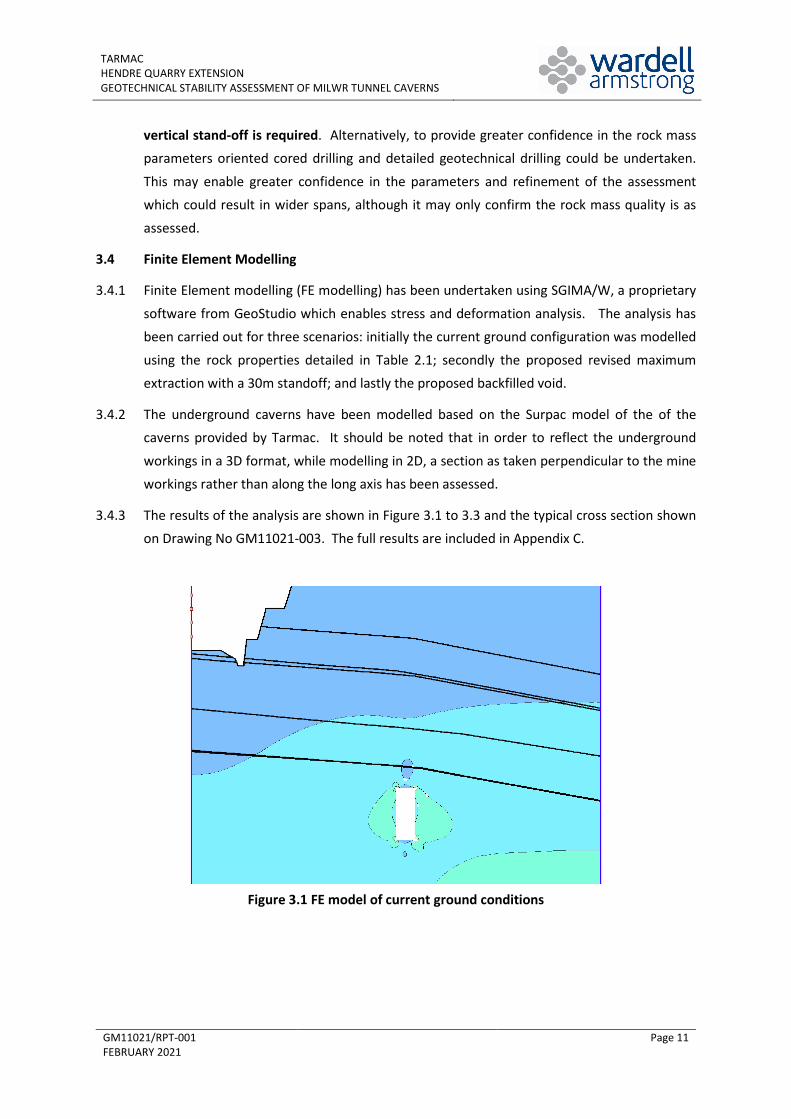
3.4.1 Finite Element modelling (FE modelling) has been undertaken using SGIMA/W, a proprietary
software from GeoStudio which enables stress and deformation analysis. The analysis has been carried out for three scenarios: initially the current ground configuration was modelled
using the rock properties detailed in Table 2.1; secondly the proposed revised maximum extraction with a 30m standoff; and lastly the proposed backfilled void.
3.4.2 The underground caverns have been modelled based on the Surpac model of the of the caverns provided by Tarmac. It should be noted that in order to reflect the underground
workings in a 3D format, while modelling in 2D, a section as taken perpendicular to the mine workings rather than along the long axis has been assessed.
3.4.3 The results of the analysis are shown in Figure 3.1 to 3.3 and the typical cross section shown on Drawing No GM11021-003. The full results are included in Appendix C.
Figure 3.1 FE model of current ground conditions
TARMAC HENDRE QUARRY EXTENSION GEOTECHNICAL STABILITY ASSESSMENT OF MILWR TUNNEL CAVERNS
GM11021/RPT-001 FEBRUARY 2021
Page 12
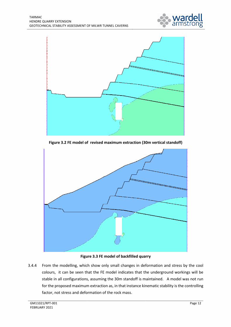
Figure 3.2 FE model of revised maximum extraction (30m vertical standoff)
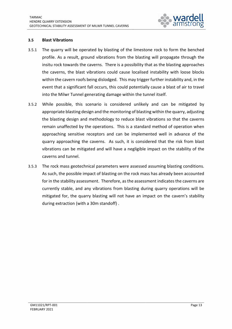
Figure 3.3 FE model of backfilled quarry
3.4.4 From the modelling, which show only small changes in deformation and stress by the cool colours, it can be seen that the FE model indicates that the underground workings will be stable in all configurations, assuming the 30m standoff is maintained. A model was not run
for the proposed maximum extraction as, in that instance kinematic stability is the controlling factor, not stress and deformation of the rock mass.
TARMAC HENDRE QUARRY EXTENSION GEOTECHNICAL STABILITY ASSESSMENT OF MILWR TUNNEL CAVERNS
GM11021/RPT-001 FEBRUARY 2021
Page 13
3.5 Blast Vibrations
3.5.1 The quarry will be operated by blasting of the limestone rock to form the benched
profile. As a result, ground vibrations from the blasting will propagate through the
insitu rock towards the caverns. There is a possibility that as the blasting approaches
the caverns, the blast vibrations could cause localised instability with loose blocks
within the cavern roofs being dislodged. This may trigger further instability and, in the
event that a significant fall occurs, this could potentially cause a blast of air to travel
into the Milwr Tunnel generating damage within the tunnel itself.
3.5.2 While possible, this scenario is considered unlikely and can be mitigated by
appropriate blasting design and the monitoring of blasting within the quarry, adjusting
the blasting design and methodology to reduce blast vibrations so that the caverns
remain unaffected by the operations. This is a standard method of operation when
approaching sensitive receptors and can be implemented well in advance of the
quarry approaching the caverns. As such, it is considered that the risk from blast vibrations can be mitigated and will have a negligible impact on the stability of the
caverns and tunnel.
3.5.3 The rock mass geotechnical parameters were assessed assuming blasting conditions. As such, the possible impact of blasting on the rock mass has already been accounted
for in the stability assessment. Therefore, as the assessment indicates the caverns are
currently stable, and any vibrations from blasting during quarry operations will be mitigated for, the quarry blasting will not have an impact on the cavern’s stability
during extraction (with a 30m standoff) .
TARMAC HENDRE QUARRY EXTENSION GEOTECHNICAL STABILITY ASSESSMENT OF MILWR TUNNEL CAVERNS
GM11021/RPT-001 FEBRUARY 2021
Page 14
4 CONCLUSIONS
4.1 Background
4.1.1 A geotechnical assessment has been undertaken to ascertain the potential effect on the stability of the underground limestone caverns from the proposed eastern extension to Hendre Quarry.
4.1.1 The assessment has been undertaken using two methods: firstly by empirical methods using the NGI Q system, which takes into consideration the rock mass quality and characteristics to
assess the potential for kinematic failure (joint controlled failures); and secondly by Finite Element Modelling (FE) which assesses stress and deformation in rock in response to
excavation of rock to determine if the underground working will remain stable.
4.2 Q System Assessment
4.2.1 A Q system assessment has been completed for base case, conservative case and less-conservative case assuming temporary mine openings and permanent mine openings. The
base case and less-conservative case indicate that the caverns are stable in medium stress regimes, and as such are considered to reflect the current underground rock mass condition.
In a low stress regime, the caverns will not stay stable except under the best rock mass conditions. It is therefore recommended that the proposed quarry excavation is stood off from
the caverns to maintain a medium stress regime condition. This will which require a 30m vertical standoff from the roof of the nearest cavern to the base or face of the quarry.
4.3 FE Modelling
4.3.1 FE modelling was undertaken using SIGMA/W a Geostudios software. Three models were assessed to represent the current configuration, the proposed revised maximum extent of
extraction and the proposed backfill level.
4.3.2 Each model showed that the revised configuration remained stable.
4.4 Blast Vibrations
4.4.1 The assessment of geotechnical rock mass properties takes into consideration the
impact of blasting on the rock mass. As such, the overall stability of the caverns will
not be impacted on by blasting within the quarry.
4.4.2 There is a small possibility that blast vibrations could cause localised instability and rock fall within the caverns. This risk can be mitigated by monitoring of the blasting
and variation of the blasting procedures to ensure blast vibrations are kept to a
minimum on the approach to the caverns.
TARMAC HENDRE QUARRY EXTENSION GEOTECHNICAL STABILITY ASSESSMENT OF MILWR TUNNEL CAVERNS
GM11021/RPT-001 FEBRUARY 2021
Page 15
4.5 Impact on Milwr Tunnel
4.5.1 The geotechnical assessment has shown that the potential impact of the proposed
quarry extension on the stability of the limestone caverns can be mitigated by
incorporating an appropriate stand-off between the quarry and the caverns. Provided
that the stability of the caverns is maintained, then there should be no impact on the
stability of the Milwr Tunnel itself due to the distance (c.300m) of the proposed
extension from the tunnel.
4.6 Recommendations
4.6.1 Based on the calculations and modelling in this report, the submitted quarry
development should be revised to make provision for a minimum 30m vertical
standoff to the caverns.
4.6.2 Appropriate procedures should be implemented by the quarry operator to highlight
any significant changes in the geotechnical stability of the quarry that may indicate
that the recommended stand-off is not sufficient. This should include face instability or deterioration in rock quality in the quarry.
4.6.3 If any significant deterioration in the stability of the limestone caverns or of the Milwr
Tunnel comes to the attention of UU or HDMDC that may have relevance to this assessment, then this should be highlighted to the quarry operator.
4.6.4 Blast vibration monitoring should be continued as per existing planning requirements.
4.6.5 The quarry operator should provide notice of the dates and times of blasting in the quarry to appropriate parties (including UU/HDMDC) such that persons are aware to
avoid entering relevant areas of the caverns and tunnel system during a blast event.
4.6.6 Prior to commencement of extraction in Phase 5 or extraction within 45m of the
roof of the caverns an updated geotechnical/ mine stability report shall be
submitted to Flintshire County Council which reviews the findings and conclusions
of this report. This will include analysis of site won geotechnical rock quality
data focusing in particular on the geological units the caverns are situated within.
This will also include analysis of the data gathered from recommendations 4.6.2 and
4.6.3 above.