Embed Size (px)
Citation preview
AFRL-IF-RS-TR-2001-46 Final Technical Report April 2001
SOFTWARE ENVIRONMENTS IN SUPPORT OF WIDE-AREA DEVELOPMENT
University of Colorado
Sponsored by Defense Advanced Research Projects Agency DARPA Order No. B126
APPROVED FOR PUBLIC RELEASE; DISTRIBUTION UNLIMITED.
The views and conclusions contained in this document are those of the authors and should not be interpreted as necessarily representing the official policies, either expressed or implied, of the Defense Advanced Research Projects Agency or the U.S. Government.
20010607 015 AIR FORCE RESEARCH LABORATORY
INFORMATION DIRECTORATE ROME RESEARCH SITE
ROME, NEW YORK

This report has been reviewed by the Air Force Research Laboratory, Information Directorate, Public Affairs Office (IFOIPA) and is releasable to the National Technical Information Service (NTIS). At NTIS it will be releasable to the general public, including foreign nations.
AFRL-IF-RS-TR-2001-46 has been reviewed and is approved for publication.
APPROVED: ft ,,-XQ., . V/ LA/-*-« \.x\ crz-f^ Y ^-J^'\
ROGER J.DZIEGIEL Project Engineer
FOR THE DIRECTOR:
JAMES A. COLLINS, Acting Chief Information Technology Division Information Directorate
If your address has changed or if you wish to be removed from the Air Force Research Laboratory Rome Research Site mailing list, or if the addressee is no longer employed by your organization, please notify AFRL/IFTD, 525 Brooks Road, Rome, NY 13441-4505. This will assist us in maintaining a current mailing list.
Do not return copies of this report unless contractual obligations or notices on a specific document require that it be returned.
SOFTWARE ENVIRONMENTS IN SUPPORT OF WIDE-AREA DEVELOPMENT
Dennis Heimbigner, Roger King, and Alexander Wolf
Contractor: University of Colorado Contract Number: F30602-94-C-0253 Effective Date of Contract: 28 August 1994 Contract Expiration Date: 26 July 2000 Short Title of Work: Software Environments in Support
of Wide-Area Development Period of Work Covered: Aug 94 - Jul 00
Principal Investigator: Dennis Heimbigner Phone: (303) 492-6643
AFRL Project Engineer: Roger J. Dziegiel Phone: (315)330-2185
APPROVED FOR PUBLIC RELEASE; DISTRIBUTION UNLIMITED.
This research was supported by the Defense Advanced Research Projects Agency of the Department of Defense and was monitored by Roger J. Dziegiel, AFRL/IFTD, 525 Brooks Road, Rome, NY.

REPORT DOCUMENTATION PAGE Form Approved
OMBNo. 0704-0188
Public reporting burden for this collection of information is estimated to average 1 hour per response, including the time for reviewing instructions, searching existing data sources, gathering and maintaining the data needed, and completing and reviewing the collection of information. Send comments regarding this burden estimate or any other aspect of this collection of informetion, including suggestions for reducing this burden, to Washington Headquarters Services, Directorate for Information Operations and Reports, 1215 Jefferson Davis Highway, Suite 1204, Arlington, VA 222024302, and to the Office of Menagement and Budget, Paperwork Reduction Project 10704-0188), Washington, DC 20503.
1. AGENCY USE ONLY (Leave blank) 2. REPORT DATE
APRIL 2001 3. REPORT TYPE AND DATES COVERED
Final Aug94-Jul00 4. TITLE AND SUBTITLE
SOFTWARE ENVIRONMENTS IN SUPPORT OF WIDE-AREA DEVELOPMENT
6. AUTHOR(S)
Dennis Heimbigner, Roger King, and Alexander Wolf
5. FUNDING NUMBERS
C - F30602-94-C-0253 PE- 61101E/62301E PR- B126 TA- 01 WU -01
7. PERFORMING ORGANIZATION NAME(S) AND ADDRESS(ES)
University of Colorado Computer Science Department Boulder CO 80309-0430
8. PERFORMING ORGANIZATION REPORT NUMBER
N/A
9. SPONSORING/MONITORING AGENCY NAME(S) AND ADDRESS(ES)
Defense Advanced Research Project Agency Air Force Research Laboratory/IFTD 3701 N Fairfax Drive 525 Brooks Road Arlington VA 22203 Rome NY 13441-4505
10. SPONSORING/MONITORING AGENCY REPORT NUMBER
AFRL-IF-RS-TR-2001-46
11. SUPPLEMENTARY NOTES
Air Force Research Laboratory Project Engineer: Roger J. Dziegiel/IFTD/(315) 330-2185
12a. DISTRIBUTION AVAILABILITY STATEMENT
APPROVED FOR PUBLIC RELEASE; DISTRIBUTION UNLIMITED. 12b. DISTRIBUTION CODE
13. ABSTRACT (Maximum 200 words!
The goal of the University of Colorado Arcadia project was to explore the problems of wide-area software engineering. Historically, the project was the second phase in a long-term Arcadia consortium of universities and companies whose goal was to advance the state of the art in software engineering environments. The Univ of Colorado Arcadia project has been successful in achieving its objective: producing innovative, useful and interesting research results in the areas of software process, software architecture, configuration management, deployment data management, distributed computing and web-data management. These research results were embodied in a number of prototype systems: undistributed computing), Process Wall (software process execution) Balboa (software process capture), Sybil (databased integration), NUCM (distributed configuration Management), SRM (software release), DVS (distributed development), Software Dock (distributed wide-area deployment), Siena (Internet-scale event notification), Aladdin (software architecture analysis), Menage (configurable software architecture), and WIT (Federating web-data). The results from this project have been widely disseminated in the form of publications software distribution to over 600 sites, technical transfers to commercial practice, and through the conferring of degrees upon quality Ph.D. and M.S. students.
14. SUBJECT TERMS
Software Environment, Distributed Computing, Remote Procedure Call, Software Process, Configuration Management, Deployment, Event Notification, Software Engineering
15. NUMBER OF PAGES
92 16. PRICE CODE
17. SECURITY CLASSIFICATION OF REPORT
UNCLASSIFIED
18. SECURITY CLASSIFICATION OF THIS PAGE
UNCLASSIFIED
19. SECURITY CLASSIFICATION OF ABSTRACT
UNCLASSIFIED
20. LIMITATION OF ABSTRACT
UL Standard Form 298 (Rev. 2-89) (EG) Prescribed by ANSI Std. 238.18 Designed using Perform Pro, WHSIDI0B, Oct 94

Abstract
The goal of the University of Colorado Arcadia project was to explore the problems of wide-area
software engineering. Historically, the project was the second phase in a long-term Arcadia
consortium of universities and companies whose goal was to advance the state of the art in
software engineering environments. The University of Colorado Arcadia project has been suc-
cessful in achieving its objective: producing innovative, useful, and interesting research results
in the areas of software process, software architecture, configuration management, deployment,
data management, distributed computing, and web-data management. These research results
were embodied in a number of prototype systems: Q (distributed computing), Process Wall
(software process execution) Balboa (software process capture), Sybil (database integration),
NUCM (distributed configuration management), SRM (software release), DVS (distributed
development), Software Dock (distributed wide-area deployment), Siena (Internet-scale event
notification), Aladdin (software architecture analysis), Menage (configurable software archi-
tecture), and WIT (federating web-data). The results from this project have been widely
disseminated in the form of publications, software distributions to over 600 sites, technical
transfers to commercial practice, and through the conferring of degrees upon quality Ph. D. and M. S. students.
Contents
Abstract i
Table of Contents ~ ü
List of Figures v
List of Tables v
1 Introduction 1
2 Background 2
3 Research Program 3
4 Results 6
4.1 Software Prototypes 7
4.1.1 Q 8 4.1.1.1 Motivation for Q 9
4.1.1.2 Q Version 1 9 4.1.1.3 Q Version 2 11
4.1.1.4 Q Version 3 13 4.1.1.5 Summary of Experience 14
4.1.2 ProcessWall 16
4.1.2.1 Background 16 4.1.2.2 The State Server Approach 16
4.1.2.3 Experience 19
4.1.3 Balboa 20
4.1.3.1 Balboa Architecture 20
4.1.3.2 Experience 21
4.1.4 Sybil 22
4.1.4.1 Architecture 23
4.1.4.2 Experience 24
4.1.5 NUCM 25
4.1.5.1 Data Model 25
4.1.5.2 Distribution Model 26
4.1.5.3 Generic Programmatic Interface 27
ii

4.1.5.4 Experience 27
4.1.6 SRM 29
4.1.6.1 Prototype 30
4.1.6.2 Experience 33
4.1.7 DVS 34
4.1.7.1 Prototype 34
4.1.7.2 Experience 35
4.1.8 Software Dock 36 4.1.8.1 Software Deployment Life Cycle 36
4.1.8.2 Architecture 37
4.1.8.3 Deployable Software Description 39
4.1.8.4 Enterprise Software Deployment 40
4.1.8.5 Prototype 41 4.1.8.6 Experience 43
4.1.9 Siena 45
4.1.9.1 Architecture 45
4.1.9.2 Interface 47 4.1.9.3 Routing Optimization 48
4.1.9.4 Experience 48
4.1.10 Aladdin 50
4.1.10.1 Dependence Analysis by Chaining 50
4.1.10.2 The Aladdin Tool 52
4.1.10.3 Experience 52
4.1.11 Menage 55 4.1.11.1 Background 55 4.1.11.2 Configurable Architecture 55
4.1.11.3 Menage Design Tool 56
4.1.11.4 Experience 57 4.1.12 WIT 58
4.1.12.1 WIT Capabilities 58
4.1.12.2 Architecture and Implementation 58
4.1.12.3 The WIT User Interface 60
4.1.12.4 Post-integration Operations 60
4.1.12.5 Summary 61
4.2 Technical Transfer 62 4.2.1 Prototype Availability 62
4.2.2 Other Technical Transfer Efforts 62
4.2.2.1 1995 62 4.2.2.2 1996 62
in

4.2.2.3 1997 62 4.2.2.4 1998 63 4.2.2.5 1999-2000 63
4.3 Students 64
5 Summary 65
6 References and Bibliography 66
7 Symbols, Abbreviations, and Acronyms ?4
IV

List of Figures
1 Q Version 1 Virtual Machine Layers 10
2 Logical Client/Server Architectures 12
3 Q Version 3 Virtual Machine Layers 14
4 Balboa Launchpad Interface 21
5 NUCM Data Model Example 26
6 NUCM WebDAV Browser Interface . 28
7 SRM Client Download Interface (using Netcape) 30
8 SRM Download Information Interface 31
9 SRM Download Dependencies Interface 31
10 SRM Upload Menu 32
11 SRM Upload Interface 32 12 SRM Upload Dependency Selection Interface 32
13 DVS Architecture 35
14 Deployment Life Cycle 37
15 Software Dock Architecture 38
16 Field Dock Main Interface 42
17 Field Dock Property Manipulation Interface 42
18 Enterprise-level Administrators Workbench Interface 42
19 Distributed Event Notification Service 46
20 Siena Event Notification Example 47
21 Siena Event Filter Example 47
22 Hierarchical Routing Example 48
23 Aladdin Specification Interface 53
24 Aladdin Query Interface 54
25 Menage Design Environment Screen Snapshot 57 26 Variant Architecture of Component Optimizer 57
List of Tables
1 Software Dock Performance Comparison 43
2 Alphabetical List of Graduated Students Associated with this Contract 64

1 Introduction
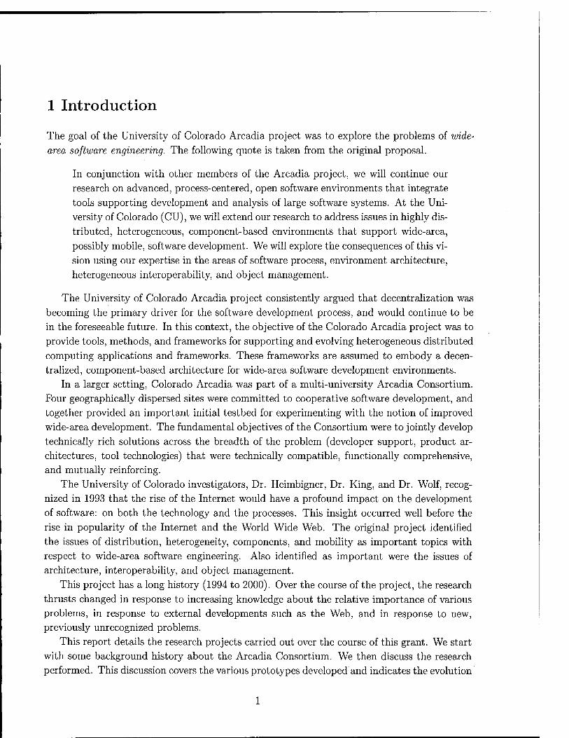
The goal of the University of Colorado Arcadia project was to explore the problems of wide-
area software engineering. The following quote is taken from the original proposal.
In conjunction with other members of the Arcadia project, we will continue our
research on advanced, process-centered, open software environments that integrate
tools supporting development and analysis of large software systems. At the Uni-
versity of Colorado (CU), we will extend our research to address issues in highly dis-
tributed, heterogeneous, component-based environments that support wide-area,
possibly mobile, software development. We will explore the consequences of this vi-
sion using our expertise in the areas of software process, environment architecture,
heterogeneous interoperability, and object management.
The University of Colorado Arcadia project consistently argued that decentralization was
becoming the primary driver for the software development process, and would continue to be
in the foreseeable future. In this context, the objective of the Colorado Arcadia project was to
provide tools, methods, and frameworks for supporting and evolving heterogeneous distributed
computing applications and frameworks. These frameworks are assumed to embody a decen- tralized, component-based architecture for wide-area software development environments.
In a larger setting, Colorado Arcadia was part of a multi-university Arcadia Consortium. Four geographically dispersed sites were committed to cooperative software development, and
together provided an important initial testbed for experimenting with the notion of improved
wide-area development. The fundamental objectives of the Consortium were to jointly develop
technically rich solutions across the breadth of the problem (developer support, product ar-
chitectures, tool technologies) that were technically compatible, functionally comprehensive, and mutually reinforcing.
The University of Colorado investigators, Dr. Heimbigner, Dr. King, and Dr. Wolf, recog-
nized in 1993 that the rise of the Internet would have a profound impact on the development
of software: on both the technology and the processes. This insight occurred well before the
rise in popularity of the Internet and the World Wide Web. The original project identified
the issues of distribution, heterogeneity, components, and mobility as important topics with
respect to wide-area software engineering. Also identified as important were the issues of architecture, interoperability, and object management.
This project has a long history (1994 to 2000). Over the course of the project, the research
thrusts changed in response to increasing knowledge about the relative importance of various
problems, in response to external developments such as the Web, and in response to new, previously unrecognized problems.
This report details the research projects carried out over the course of this grant. We start
with some background history about the Arcadia Consortium. We then discuss the research
performed. This discussion covers the various prototypes developed and indicates the evolution

of the research over time.
2 Background
The original Arcadia project has a long history dating back to 1985. It was originally funed
by DARPA to carry out research into software engineering environments. The original project
chose the Ada programming language as the target for the environment to be developed.
The original Arcadia project was set up as a consortium of three Universities and three
companies.
• University of California, Irvine,
• University of Colorado, Boulder,
• University of Massachusetts, Amherst,
• TRW, Inc.,
• Aerospace Corp,
• Incremental Systems.
The intent was that the Universities and Aerospace would do the research, Incremental Systems
would provide an Ada Compiler, and TRW would act as integrator.
Over time, the makeup of the consortium changed, both Aerospace and Incremental Sys-
tems left because of resources problems. Purdue University was added when one of the students
from Irvine moved to Purdue and was given a subcontract to participate in the consortium.
This project (the subject of this report) was funded as a result of the DARPA/SISTO BAA
#93-11 on Environments. The program managers at the time were Lt. Col. Eric Mettala and
Dr. John Foreman. The topic was Advanced Environments. By the time that this grant was
awarded, the project manager was Dr. John Salasin.
In late 1995, Dr. Salasin initiated the Evolutionary Design of Complex Software (EDCS)
program under DARPA SSTO BAA #95-40. The program was designed to address problems
in constructing complex software systems. In late 1996, the Arcadia contracts were folded into
this program and some changes in research direction occurred at that time. The University of Colorado obtained a separate DARPA-funded contract (Air Force contract F30602-98-2-
0163) that came from the EDCS program. This separate contract was closely allied with the
Arcadia contract and there is substantial overlap both in personnel and research between the two projects.
In 1998, this project was given no-cost extensions to take it into the year 2000, a date which
corresponded closely with the termination of the EDCS program. The extension came about
for two reasons. First, the research direction of the project was changed in consultation with

DARPA to focus more directly on configuration management. Second, the funding for this
project had been highly variable, especially in 1996-1998. The extensions provided a means to
smooth out the funding profile and support better integration with EDCS. The project finished
in July of 2000. The University of Colorado was the last of the original Arcadia participants
funded by DARPA.
3 Research Program
Our initial vision for Arcadia environments was driven by a belief that they must become
capable of supporting wide-area, possibly mobile, software development. We saw development
evolving more and more toward an activity involving people and groups that are geographically
and organizationally dispersed. Clearly, such a trend significantly exacerbates the coordination
problem for software projects, since management - and support for that management - cannot
be effectively centralized nor homogenized. We initially attacked the problem of decentralized software development with a three-
pronged approach:
1. distributed, heterogeneous, object architectures,
2. tool and information interoperability,
3. coordination of the development processes between dispersed locations.
Carrying out this approach required Arcadia environments to evolve in the direction of
highly distributed collections of heterogeneous components. We saw no technology other
than component-based systems capable of providing the needed flexibility. In line with this,
our goal was to explore the various consequences of such a component-oriented approach,
and specifically software process, environment architecture, heterogeneity, and configuration
management. Our initial research prototypes were as follows.
1. Process Wall -■ addressed the problems of distributed software process execution and the
architecture of process-driven environments.
2. Balboa -- addressed capture of software process.
3. Sybil addressed the problems of heterogeneous interoperability of databases and prob-
lems of distributed data management. This system was previously named Amalgame.
4. Q - addressed the problems of distributed component-based environment architectures
and the problems of interoperability of component written using a heterogeneous collec-
tion of programming languages.
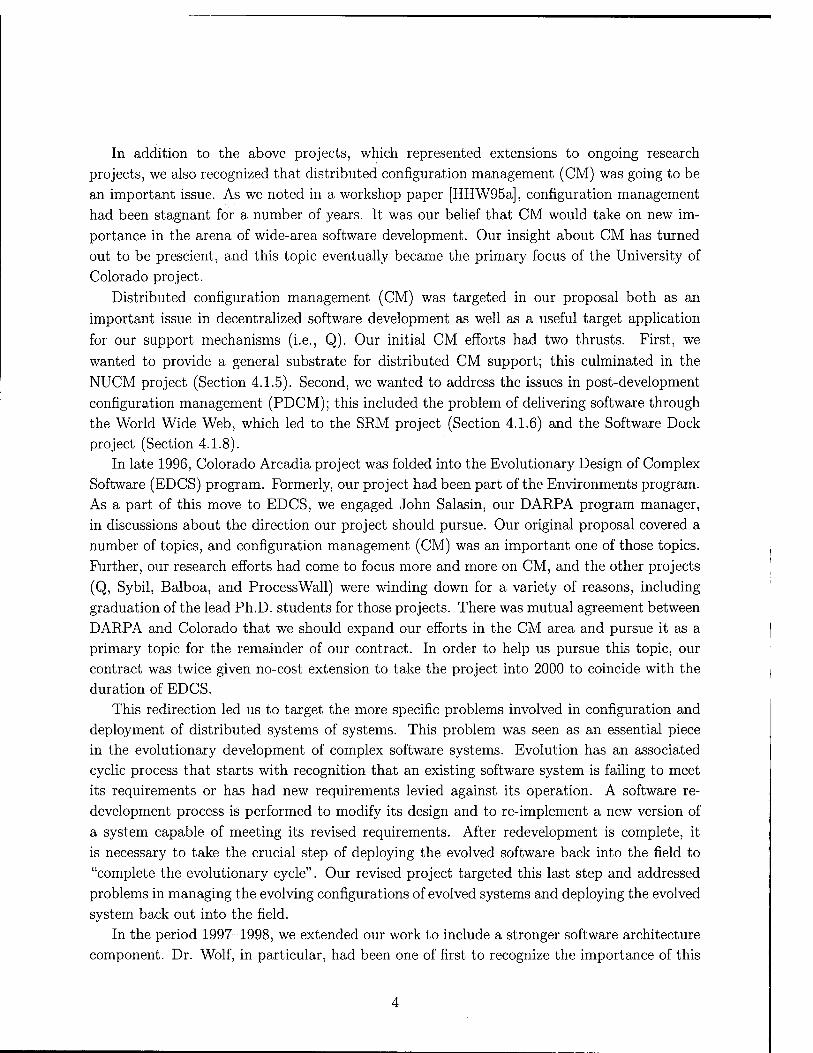
In addition to the above projects, which represented extensions to ongoing research
projects, we also recognized that distributed configuration management (CM) was going to be
an important issue. As we noted in a workshop paper [HHW95a], configuration management
had been stagnant for a number of years. It was our belief that CM would take on new im-
portance in the arena of wide-area software development. Our insight about CM has turned
out to be prescient, and this topic eventually became the primary focus of the University of
Colorado project.
Distributed configuration management (CM) was targeted in our proposal both as an
important issue in decentralized software development as well as a useful target application
for our support mechanisms (i.e., Q). Our initial CM efforts had two thrusts. First, we
wanted to provide a general substrate for distributed CM support; this culminated in the
NUCM project (Section 4.1.5). Second, we wanted to address the issues in post-development
configuration management (PDCM); this included the problem of delivering software through
the World Wide Web, which led to the SRM project (Section 4.1.6) and the Software Dock
project (Section 4.1.8). In late 1996, Colorado Arcadia project was folded into the Evolutionary Design of Complex
Software (EDCS) program. Formerly, our project had been part of the Environments program. As a part of this move to EDCS, we engaged John Salasin, our DARPA program manager,
in discussions about the direction our project should pursue. Our original proposal covered a
number of topics, and configuration management (CM) was an important one of those topics.
Further, our research efforts had come to focus more and more on CM, and the other projects
(Q, Sybil, Balboa, and ProcessWall) were winding down for a variety of reasons, including
graduation of the lead Ph.D. students for those projects. There was mutual agreement between
DARPA and Colorado that we should expand our efforts in the CM area and pursue it as a
primary topic for the remainder of our contract. In order to help us pursue this topic, our contract was twice given no-cost extension to take the project into 2000 to coincide with the duration of EDCS.
This redirection led us to target the more specific problems involved in configuration and deployment of distributed systems of systems. This problem was seen as an essential piece in the evolutionary development of complex software systems. Evolution has an associated
cyclic process that starts with recognition that an existing software system is failing to meet
its requirements or has had new requirements levied against its operation. A software re-
development process is performed to modify its design and to re-implement a new version of
a system capable of meeting its revised requirements. After redevelopment is complete, it
is necessary to take the crucial step of deploying the evolved software back into the field to
"complete the evolutionary cycle". Our revised project targeted this last step and addressed
problems in managing the evolving configurations of evolved systems and deploying the evolved
system back out into the field.
In the period 1997-1998, we extended our work to include a stronger software architecture
component. Dr. Wolf, in particular, had been one of first to recognize the importance of this
topic. Architecture specifications promised to provide detailed component and relationship
information not previously available, but which we saw as the essential basis for making de-
ployment and configuration management possible and effective. At this time, two architecture
related projects were initiated. The Aladdin project (Section 4.1.10 was started with the goal
of providing for the analysis of software architectures. The Menage project began to address
the combination of configuration management with architectures. It added the configuration
concepts of variability, optionality, and evolution to architectural descriptions.
Combining architecture with our CM work, caused us to develop this more systematic
characterization of our work.
The University of Colorado SERL project is addressing the challenge of the config-
uration and deployment of systems of systems developed by multiple organizations
at multiple physical locations over a wide-area network.
We recognized that solving this challenge impacted several areas of software development:
• managing system structure — software architecture;
• managing system evolution by developers — configuration management; and
• managing system configuration, deployment, and continued evolution in the field —field
configuration and deployment management.
In this time frame, the DoD began to be explicitly cognizant of the problems of wide-area
operations. DOD operated over 100 wide-area networks, and this number was going to increase
as a result of [then] new programs such as Battlefield Awareness (BADD) and Command Post
of the Future (CPOF). The stated goal underlying this trend was to enable the movement of
information at all levels, replacing the movement of people with the movement of information.
Inherent in the existence of these global networks is an opportunity to leverage the con-
nectivity of the network for software artifact distribution, and this was, of course, exactly the
target of our research. We were now able to be clearer about the advantages of network-based configuration and
deployment:
• Timeliness — As soon as a new software system version or update becomes available,
users can be given access to it.
• Continuous evolution — The semi-continuous connectivity offered by a network allows
software producers to offer a much higher level of service to software consumers, moving beyond mere installation to encompass other activities such as activation, update, and
adaptation. The resulting benefit is a lower total cost of ownership because less effort
must be expended by the end-user on maintaining deployed software.
•
Reuse — The systems developed by software producers are more visible and more eas-
ily incorporated into larger systems, thus enhancing the reuse of a given system and
promoting the development of systems of systems.
Storage — Network distribution creates a form of ternary storage, where access to soft-
ware appears to be "always" available without necessarily requiring that the software reside in local, possibly limited, secondary storage.
In the period 1999-2000, the project description remained essentially stable. Dr. Ken-
neth Anderson joined us from the University of California, Irvine, and his Chimera hypertext
work was folded into the Colorado Arcadia effort. We also added one new area: "managing
artifacts from multiple autonomous network sources." This item reflected the WIT project
(Section 4.1.12), which is focused on integrating distributed collections of electronic documents
produced by multiple, autonomous organizations.
The project completed in July of 2000, and it is fair to say that it has been a success; it
has produced significant research results, has conferred graduate degrees on a number of good
students, and has had significant impact within DARPA and within the larger configuration
management community, the software process community, the database community, and the software architecture community.
4 Results
The detailed accomplishments of this project fall into four categories: software prototypes, technical transfer, Ph. D. and M. S. students graduated, and publications. The first three are
detailed in the following sections. A reverse chronological list of all publications is provided in Section 6.

4.1 Software Prototypes
The main vehicle for our research has been the development of a number of research prototype
software systems, each of which embodies important new capabilities. The following prototypes
were developed in whole or part under this project.
1. Q - a toolkit for rapidly constructing distributed systems using remote-procedure call
for communication and coordination; Q especially emphasized heterogeneity through
support for multiple programming languages.
2. ProcessWall - a client /server architecture for managing executable software processes
emphasizing the separation of the state of the process (maintained in the server) from
the process program formalisms (represented by clients).
3. Balboa - a framework for separating the collecting, managing, interpreting, and serving
of software process (i.e., workflow) event data from the tools for analyzing that data.
4. Sybil - a framework for partial integration of databases that provides incremental, rule-
based, integration of parts of multiple Schemas.
5. NUCM - a generic, tailorable, peer-to-peer repository supporting distributed Configu-
ration Management.
6. SRM - a tool to manage the release of multiple, interdependent software systems from
distributed sites.
7. D VS - a tool to support distributed authoring and versioning of documents with complex structure, and to support multiple developers at multiple sites over a wide-area network.
8. Software Dock - a distributed, agent-based framework supporting software system de-
ployment over a wide-area network.
9. Siena - an Internet-scale distributed event notification service allowing applications and
people to coordinate in such activities as updating software system deployments.
10. Aladdin - a tool for analyzing intercomponent dependencies in software architectures.
11. Menage - an architectural environment that adds the configuration concepts of variabil-
ity, optionality, and evolution to architectural descriptions.
12. WIT - a tool providing unified access to multiple Web data sources by applying federated database techniques.
The objectives, approach, and contributions of these prototypes are described in the following sections.

4.1.1 Q
Q is especially important because it represents the first, and one of the most successful, software prototypes produced by this project.
Q provides both remote procedure call (RPC) and message-passing semantics as a layer above Unix sockets. It supports both the Open Network Computing (ONC) industrial stan-
dard used in NSF, as well as the CORBA2 HOP standard. Q is especially strong in supporting
multiple programming languages: currently Ada, Java, Tel, C, and C++. Q defines an inter-
process communication model and a type space common to multiple languages. Additionally,
Q provides flexible architectures for client-servers, including arbitrary binding of clients and
servers into address spaces, mixed RPC and messages, and support for CORBA-like objects.
In the Q model, a distributed system is one that is implemented as a collection of com-
ponents that interoperate with each other, but which execute in separate address spaces, and
may execute on separate hardware/software platforms. Distributed systems offer a number
of important advantages over systems implemented as a single process running on a single
platform. Distributed systems may be more robust, as it is possible to implement key services redundantly on different hardware and/or software platforms. Distributed systems may be faster as it may be possible to effectively parallelize bottleneck jobs. Distributed systems may be more flexible and extensible, as changes may be quarantined to smaller subsystems, and may be carried out without the need for change to the entire system. Distributed systems
may be more effective in reusing sizable components, as these components are less likely to
require re-compilation and reloading. Distributed systems may be composed of components implemented in differing languages and dialects.
These advantages are particularly important to the implementors of software environments.
Software environments are notoriously large, restricting their flexibility, extensibility, and abil-
ity to reuse existing componentry. On the other hand it is essential that software environments
be highly flexible and extensible as most will need to undergo continuous change and enhance-
ment. If an environment is implemented as a distributed system, consisting of separately
compiled components, the required flexibility and extensibility can be achieved, often by re- configuration using existing components, such as off-the-shelf database systems. As many
environments are still experimental prototypes, it is particularly important that they be able
to rely upon support from diverse, possibly competing, components, possibly written in dif- ferent languages. Distribution also facilitates this.
Arcadia took this approach to distributed components seriously and as a group, we were one of the first to do so. Q was critical for producing distributed environments for Arcadia. Many
of the tools produced by the Arcadia Consortium made use of Q either to provide various
services or to support the construction of larger programs out of independently developed components.

4.1.1.1 Motivation for Q
Q has co-evolved over a period of years with the needs of the Arcadia environments. That evolution was driven by a cycle involving experience with Q in the context of some Arcadia project. This experience would lead to a crisis in handling some important problem, followed by extending and modifying Q to address the problem successfully.
Generally speaking, the problems that Q encountered and overcame have been related to issues of heterogeneity. Arcadia systems were built intentionally to be heterogeneous with respect to computing platform hardware, operating systems, and especially programming lan- guages. The latter point is worth expanding upon since from its inception, Arcadia used a variety of languages, including C, C++, Ada (both 83 and 95), Java, Tel, Lisp, and even Pro- log. The result was an extensive, tested Q library for inserting distributed object capabilities into almost any programming language.
This need to support heterogeneity was eventually understood more widely in the com- munity, and now some alternatives exist to address these needs. CORBA and DCOM, for example. From our current perspective, however, we see that, even had CORBA been avail- able to us in its present form at the beginning of our project, it would form only a part of a solution to our problems. For example, CORBA is avowedly an attempt to provide for multi-lingual interoperability, but its primary thrust is most clearly and sharply towards inter- operability among clients and servers written in C and C++ (and more recently Java). Also, it is oriented toward traditional client-server architectures while Q has moved on to support peer-oriented architectures. Further, CORBA has made assumptions about concurrency and threading that Q rejects in order to expand its ability to support more platforms.
4.1.1.2 Q Version 1
For largely pragmatic reasons the Open Network Computing (ONC) specifications for Remote Procedure Call (RPC) and External Data Representation (XDR) was chosen as the initial basis for the construction of our language-heterogeneous interoperability mechanism. The version 4.0 release of RPC/XDR from Sun Microsystems was a public domain implementation that included the source code. This made modifications easy. Sun had a vested interest in ONC because the ONC standard is the RPC which underlies Sun's Network File System (NFS). This had the result that ONC was, and still is, the most widely available RPC system. There were also good scientific reasons for this choice of RPC system. The ONC implementation already solved some key requirements of the interoperability system: it supported autonomous components communicating across process and platform boundaries. That seemed to leave only the task of adapting the model to provide multi-language support.
ONC RPC/XDR provides the ability to exchange meaningfully typed data values between two processes. This model supports a procedure call abstraction of inter-process commu- nication, allowing one process to make a procedure call to another process — even across machine boundaries and independent of machine architectures — and have ONC/RPC handle

Ada Interface
C Interface
C++ Interface
ONC RPC Interface
ONCXDR Interface
Message Transport Interface
Figure 1: Q Version 1 Virtual Machine Layers
the details of data marshaling and inter-process communication.
Data marshaling is the process of arranging data in a language and architecture indepen-
dent format prior to dispatching it in a message. This is to insure that the structure and
contents of the data values are preserved.
ONC supports communication between two processes written in the C language. Its inter-
faces are written in C and make use of semantic constructs which are not supported in other
languages such as Ada (such as procedure variables). Additionally, its data representation
does not define any mapping to assure the consistency of types when passing data between different type models.
Operating under the assumption that it would be possible to layer heterogeneous lan-
guage support atop a standard communications interface, a new and improved interoperabil- ity mechanism was conceived. Figure 1 depicts the virtual machine layers of the resulting
interoperability mechanism. A variety of language interfaces rest upon a standard remote
procedure invocation interface (ONC/RPC) with a separate argument marshaling interface (ONC/XDR). Underlying this is a basic data transport mechanism supporting the system's physical message transport needs.
A variety of language interfaces were constructed to explore the flexibility of the underlying support mechanism and the model in general. These languages included Ada, C, C++, Lisp,
and Prolog. For historical reasons, Ada was important within Arcadia, and so much of our
effort focused on making C, C++, and Ada interoperable. These were the implementation
languages used by the bulk of the Arcadia software tools being supported.
Problems were encountered with both the ONC RPC and XDR interfaces while trying to
adapt them for use from multiple languages. Problems with the ONC/RPC interface centered
around its dependence on features found in C (its implementation language) which are not present in many other languages (e.g., Ada). Problems with the ONC/XDR interface revolved
around its implicit assumption that all data to be marshaled would be instances of C types.
The ONC implementation of RPC handles this issue by requiring that the application
provide the generic remote call procedure with explicit marshaling procedures. At each remote
call, the client provides the procedures necessary to marshal the argument list and unmarshal
the return value. Similarly, on the server side, the server application must register each service
routine with a set of procedures to perform the argument unmarshaling and the return value marshaling.
10

While this model provides a clean procedure call abstraction for interprocess communica- tion when all procedures are written in a language such as C, it breaks down for procedures written in other languages, most notably Ada, which does not permit procedure parameters. It is therefore necessary to incorporate a modification to the ONC/RPC model to resolve this problem.
Problem: Blocking IO Simultaneous remote procedure call activity (due to any combina- tion of simultaneous client and/or server activity) was not properly handled by the original Q design. A remote procedure call is built from an exchange of two messages between a client and a server. Clients await response messages from servers and servers await request messages from clients. The problem with simultaneous RPC activity becomes apparent when two or more threads of control (e.g., Ada tasks) are awaiting messages at the same time. The ONC/RPC implementation underlying Q uses the Unixtm select system service call to await messages. The select system service listens for IO activity, incoming messages in this case, on a set of IO channels and returns to its caller when there is some IO pending on one or more of those channels. When multiple tasks are awaiting messages, multiple calls to the select service will be outstanding - all waiting on the same IO channels. The select system service is not designed to be used in this manner, and its semantics under these conditions are undefined. In this situation, the observed behavior of Q was unpredictable. Sometimes remote calls would succeed, sometimes not; sometimes the system would hang.
4.1.1.3 Q Version 2
Emerging environment architectures, using multi-threaded components each maintaining mul- tiple simultaneous client and server interfaces, led to a realization that Q's language support must encompass thread support in multi-threaded languages. Significant restructuring of the Q system was needed to support the ability to embed multiple clients and/or servers in a single process (Figure 2). The result was a new design separating the application architecture from its process binding.
IO Multiplexing Support In the single threaded Q model of version 1, each language interface was only a relatively thin veneer over the remote procedure call interface substrate. This interface (ONC/RPC) was also based upon a single threaded execution model. Multiple execution threads, initiated from multiple simultaneous tasks in Ada applications, were trying to block on select calls simultaneously. The resulting behavior was unpredictable, and usually erroneous. What was required was an IO multiplexing capability to resolve multiple requests for IO availability into a single select call.
To facilitate this the ONC/RPC infrastructure was re-engineered and extended to produce the Augmented Remote Procedure Call (Arpc) interface. Among other things, the new infras- tructure exposed a message passing interface for client/server interactions. Where previously a
11

Client Client Client
ser ver
Server
Client
Client
Client
Server
Server
Server
Server
Server
Client
Client
Client
Figure 2: Logical Client/Server Architectures
client made a single call to clnt_call, now the client took two steps: message send followed by- message receive. Note, by the way that a message passing interface has always been exposed on the server side. It was this separation into two parts that allowed for the multiplexing of many requests without causing undesirable blocking.
General Architecture Support The purpose of introducing the 10 multiplexing facility to the Ada interface was to be able to support more general component architectures. Q was developed to support the sort of architecture depicted in Figure 2a. However, experience with the some Arcadia components demonstrated that Ada's inherent multi-tasking abilities could and would be leveraged upon in order to construct more complex application architectures than originally imagined. Already applications were combining multiple clients into single components (Figure 2b), and other components would require multiple servers embedded into a single application as well (Figure 2c).
The logical progression depicted in Figure 2 is towards increasingly arbitrary combinations of communicating clients and servers. These figures represent combinations of "pure" clients and "pure" servers communicating. This might be thought of as a sequence of logical architec- tures for collections of clients and servers. The new Q design supports this concept by allowing arbitrary mappings of these logical architectures onto component processes. The original ex- pectation was that this binding would usually be one-to-one: that is, each client and server would occupy a single application process. But experience has demonstrated that other bind- ings are clearly desirable. Q has been designed to allow essentially arbitrary binding of clients and servers to processes. We should note that even today, most CORBA implementations do not provide this level of flexibility.
Of particular interest amongst the possible mappings is the peer architecture. This is a mapping of both a client and a server into each process such that each process may either initiate, or respond to, remote procedure requests. This is required when callbacks from a "server" to its "client" are needed. Examples of this behavior occur when a service procedure may run for an unbounded amount of time and the client does not wish to await the outcome,
12

or when a server wishes to inform clients of events of interest to them. This behavior is frequent
in user interface applications, where it is desirable that the interface remain responsive even
while engaged in lengthy service operations.
The solution to this problem was to move from a synchronous I/O model to an event-
based asynchronous model. Instead of having the multiplexor poll for interprocess messages,
the data channels are configured for asynchronous I/O. When a message arrives an event (e.g.,
a Unix signal) is sent to the process. Therefore, processor time is only used for interprocess
communication when it is known that data is pending. Most significantly, the synchronization
from signal to multiplexor was modified to use the native language synchronization mechanisms
such as the select mechanism for Ada. Because of this change, the issue of time slicing was
moot because the Ada runtime system now correctly handled the blocked multiplexor and so
did not waste time slices.
The second Q problem uncovered at this time was more subtle and insidious. The symp-
toms of this problem were occasional irreproducible errors in the message substrate: messages
being lost, messages delivered twice, and messages apparently being delivered to the wrong
recipient.
The problem was that while the Ada interfaces had been re-engineered to support general
multi-client/multi-server (i.e., a multi-threaded) architectures, the Arpc substrate was not.
The Arpc substrate is written in the C language and relies on the standard C libraries sup- plied with all C compilers. Arpc is non-reentrant partly because in general, so are standard C
libraries. A characteristic of non-reentrant code is the use of unprotected global data struc-
tures. In a multi-threaded application, two threads of execution attempting to manipulate
such global data are likely to produce errors. A solution to this problem was incorporated as
a key new feature of the third version of Q.
4.1.1.4 Q Version 3
Once identified, the solution to the non-reentrant interface problem required a clear two-fold approach. First, a non-blocking message passing interface was constructed between the Arpc
interface and the language dependent interfaces. Second, calls into the non-blocking interface were protected against reentrant access with semaphores. The resulting Q architecture is
presented in Figure 3. This re-design coincided with the realization that the multi-threaded
architectures that supported peer-style inter-component communication were becoming the norm rather than the exception within the Arcadia project.
Careful readers may realize that, based on the earlier discussion of the evolution of Q,
the current Q substrate interface should already be non-blocking. This was largely true. The
blocking interface had been isolated to the 10 multiplexing interface and that had been con- verted from synchronous to asynchronous. However, it was at this point in the Q development
that the true value of a non-blocking interface was realized and formalized.
13

Ada Interface
C Interface
C++ Interface
Non-Blocking Procedural Interface
Marshaling Interface
Standard RPC Interface
Standard Data Representation
Interface
Message Transport Interface
Figure 3: Q Version 3 Virtual Machine Layers
Experience with Version 3 At this point, Arcadia's use of Q had become ubiquitous.
Q was the foundation for interoperability in that environment. Q version 3 has also been
distributed to over 100 other sites. It has been used by SAIC, Loral, Stars project participants,
and NASA Goddard. Although improvement of Q has stopped, it is still occasionally being
picked up by new users. The majority of sites are using Q because of its support for multi-language interoperability,
and specifically its support for Ada. Q is also being used successfully in software evolution
projects, where it supports the ability to interoperate with old components as large systems
transition from one implementation language to another. Feedback continues to be quite
positive, however there is ever increasing demand for more supported platforms and languages.
Interest in the Tcl/Tk and Java languages spurred efforts to provide Q interfaces for these
languages. In the space of a few weeks interfaces for both of these languages were constructed and tested. In the case of Java, we provided the first RPC system for Java by using Q. Support for Tcl/Tk was challenging because the language already provides 10 event management ser-
vices. The Q support was embedded cleanly within an existing master event control structure. The Java language offered the challenge of supporting a concurrent interpretive language. It
required under 500 lines of Java code and under 400 lines of C code to provide a set of in-
terfaces to produce a working version of Q in Java. The rapidity and ease with which Q was
inserted into both of these languages provides clear validation of the claims for multi-language
support with Q.
4.1.1.5 Summary of Experience
Continuing experience with, and evaluation of, Q revealed deep problems arising from recogni- tion of increasingly taxing demands. Original assumptions that time-slicing executives could
be relied upon turned out to be incorrect, and the need to accommodate asynchronous commu-
nication was realized. Further, complex systems showed the need for support of peer-to-peer
(in addition to client-server) interprocess communication. Is is now clear that effective, safe,
14

deadlock-free, and efficient support for peer-peer and client-server interprocess communication between components cannot be provided by a simple RPC model. The revised Q model now meets all of these needs.
Much of Q's development has been driven by experience with the various application and infrastructure components in the Arcadia project. Q has become the major mechanism used to support the interoperability needs of Arcadia and almost every component in that environment utilized Q. Arcadia demonstrations have typically been run on a network of Sun and DEC workstations, and considerably greater heterogeneity and distribution are possible.
15

4.1.2 ProcessWall
The ProcessWall is a client/server architecture for managing executable software processes
emphasizing the separation of the state of the process from the process program formalisms.
The server (or servers) provide persistent storage for the state of a set of executing software
processes. The clients access that state to manipulate it based on their specific process program
in some specific formalism. The server also generates event notifications indicating important
state changes. Clients can subscribe to receive those events of interest to them, and can
respond to those events to introduce further changes in the state.
4.1.2.1 Background
Much of the research into process programming has been concerned with the formalisms needed
to model and support processes. These formalisms are typically made explicit through process
programming languages (PPL's) whose purpose is to support the definition of specific processes. These formalisms may be divided into two classes: modeling and execution (or enaction). Modeling formalisms emphasize concise descriptions of the normal operation of a process and intentionally ignore many details of a process in order to achieve a concise and clear description.
Process formalisms for execution are designed to drive so-called process-centered environ-
ments. A process-centered environment is one in which the programmer is guided in the task
of producing software according to some methodology. Such an environment extends the more
traditional tool-oriented environment by adding the capability to specify the process by which
software is to be constructed. This is in contrast to a typical tool based environment in which
the programmer is presented only with a collection of tools and is given no help in deciding
how to apply those tools to produce a software product.
Most of the work in process programming was concerned with the definition of appropriate
process languages. What was missing was a consideration of how, concretely, such languages
could be used to drive an environment. Additionally, there was some dispute about the correct style of programming to be used in executable process programs: specifically rule-
based versus procedural. Each style has its merits and demerits, and at the time that the
this project began, no one had proposed a satisfactory method by which multiple styles and
multiple process languages could usefully co-exist in an environment.
4.1.2.2 The State Server Approach
The ProcessWall is the name of the prototype state server based on a new approach to manag-
ing software process driven environments. The term "ProcessWall" represents a generalization
of the "project walls," which are real walls used in some aerospace companies to provide a
graphic representation of the current state of some project.
The ProcessWall is a client-server architecture. The (state) server provides storage for
process states. The server also provides an interface with operations for defining and manip-
ulating the structure of those states. The key novel idea is that a state server allows for the
16

Separation of the state of a software process from any program for constructing that state. Instead, separate client programs implement the processes for operating on the process state. Thus, rather than focusing on the process program (written using some specific process lan- guage), the state server stores the state of a process in execution. It says as little as possible about how a process state is constructed and instead focuses on the structure of the process state and the legal modifications that can be applied to that state.
The primary merit of the state server approach is the separation of the state from the process programming language. This pushes the language complexities (e.g., style, reflection, exceptions) out to the clients of the state server. This in turn allows for interoperability between different code formalisms (i.e., mixing different process languages) as long as they adhere to a common state structure. This style problem (rule-based versus procedural) was mentioned above, and the state server approach provides a means by which the two can usefully co-exist.
Process State Server Architecture. The state server architecture is implemented as a straightforward client-server architecture. Client processes (in the operating system sense) communicate with a server process using remote-procedure calls (RPC). The server is com- posed of a number of modules:
Server Interface: This module handles the details of receiving requests from clients, invoking the appropriate local procedure to field the request, and returning any result back to the client.
Catalog: This module maintains a queryable meta-database of information about the struc- ture of the process state (process goal types and product types).
Event Dispatcher: This module provides functionality similar to that of Siena (Sec- tion 4.1.9). It maintains a database of clients registered to receive events along with the event patterns defining the events of interest to each client.
Process States: This module creates and maintains the actual state and product informa- tion. Its general structure must be in conformance with the schema elements defined in the catalog.
Persistent Storage: This module supports state persistence. It is intended to support the long duration processes common to process programming. In practice, it is also respon- sible for providing concurrency control.
Task Representation. In the ProcessWall, a process state is represented as a directed acyclic graph (DAG) of task nodes, which are instances of some collection of task types. Within a graph, the node instances are connected by two kinds of edges. One edge type in this graph has the semantics of "has-subtask", or inversely "is-subtask-of." The other class of edge in the ProcessWall formalism has the semantics of "precedes."
17

Product Representation. As the other part of the formalism, there must be some rep-
resentation of the product (broadly construed) that is being produced by the process. The
product can be expected to include more than just the final code. It will consist of a con-
stellation of data objects (e.g., requirements, design, configurations) that are produced during
the execution of the process. This additional information about the graph is maintained by
annotations (attributes) associated with each graph node or edge. A type system is associated
with product data and supports types such as scalars, abstract objects (i.e., unique identifiers), and strings.
State Change Notifications. Changes in the state of the process state server represent
events of which clients should be notified. For example, an event can provide one means for
connecting a task and a tool. When a specific task is added to the process state, this can
be defined to signal an event with a specific structure. This event can be fielded by the tool
responsible for satisfying tasks of that type.
Events are generated in two ways. First, process state and product state changes generate
events. Second, the dispatcher interface is exposed to clients, so they may generate arbitrary events as well. Clients must register with the dispatcher in order to receive signaled events.
Note that there is no need to have the dispatcher accept events from outside. The equivalent
effect can be had by defining a client to capture those external events and perform whatever state actions are required.
Client Paradigms Given a state server with the architecture as described previously, one
is left with the question: how does one actually use it? This reduces to the problem of
constructing clients to define a process state and to manipulate it through the server interface. Clients are, ultimately, arbitrary programs, and so it is difficult to crisply characterize all
possible client "paradigms." Nevertheless, it is possible to discern four rough classes of clients: tools, process-constructors, user-intermediaries, and process-constrainers.
Tools are what you might expect; they are monolithic independent programs for performing
some action such as "compile the input and leave the result in the output." Typically a tool
is associated with a leaf task in the process state. When the task is instantiated, the tool is
invoked. When the tool completes successfully, the task is marked as satisfied. Tools may
be interactive, which means that from the point of view of the process, the associated task is non-deterministic.
User-intermediaries are client programs that have a user-friendly interface and allow users
to access and manipulate (within limits) the state of the process. Thus, for the ProcessWall, "user enacted processes" are treated very much like automatic processes in that both appear
to be clients of the state server. The user processes, though, have provisions for interacting
with users via an additional specialized interface. This has the advantage that multiple user roles can be supported through differing client programs.
Process-constructor clients have the responsibility for expanding the set of tasks in the
18

process state. Within this category, it is possible to identify a variety of clients which may
be characterized as process-constructors. This variety directly reflects the range of possible
styles for constructing processes. Broadly, it is possible to distinguish three sub-classes of
constructors:
1. Procedural constructors operate "top-down." These clients looks for a task of a given
structure and expands it by adding a fixed set of subtasks. This is more-or-less
"backward-chaining" or "procedure-call."
2. Rule-based constructors operate "bottom-up." These clients looks for a collection of
tasks, creates a new task, and converts the collection of tasks into subtasks of the new
task. This may be viewed as a form of forward chaining. Sometimes, the supertask may
already exist in the process state, and this kind of client can act to merge previously
independent process fragments.
3. Planning constructors are actually a generalization of procedural constructor. A planning
system would look at the task to be expanded, and at a range of tasks actions and try to
create a specific set of subtasks to satisfy the parent task. A procedural constructor can be seen as a rather simplistic planner in that it uses the same plan (sequence of subtasks)
for every parent task. A true planner might produce different subtasks depending on
additional information such as the input values associated with the parent or knowledge
about the product state.
Process constrainers are the fourth identifiable class of client. This is a client that is
responsible for checking and enforcing any constraints on the legal structure of the process and product state. Constraint in this context should not be thought of only as a predicate, but
rather as an arbitrary piece of code which examines the state of the process server and decides
if it is acceptable or not. The code of the client might have been generated automatically from
a predicate, but it could be constructed in some other fashion as well. In a typical situation, a constructor client might add tasks to the state. These tasks would
generate events that would cause the activation of some set of constrainers. The constrainers
would examine the state and if any constraint were violated, then the constrainer would
initiate some form of repair. Repair might entail modification of the state, or even rollback by
detaching the new tasks from the task graph and possibly even destroying tasks.
4.1.2.3 Experience
A prototype of the ProcessWall was constructed. The server was implemented in C++, while
clients were implemented in multiple languages (C++, Tel, and Java) to illustrate the ability
of the ProcessWall to support heterogeneous clients. The ProcessWall was demonstrated at the first EDCS Demo Days in Seattle. A version was publically released shortly thereafter.
The concepts of the ProcessWall were picked up by Dr. Alfonso Fuggetta and applied in a
workflow system for Telecom Italy.
19

4.1.3 Balboa
Balboa is a framework for consistently managing, interpreting, and serving process event data
to analysis tools. The advantages it gives derive from the decoupling of both the data collection
and the tool construction from the format and access methods of the data. This separation of
tools from data format and management facilitates the construction of tools and allows them to access data from a wider variety of sources.
Software process engineering has an advantage over other disciplines in that much of its
activity takes place on computers. Thus, it is more amenable to reducing the effort needed for
process tracking and analysis, key practices in having a continuously improving process and
in the consistent on-time delivery of reliable, profitable software. Indeed, in the past several
years, there have been efforts to collect process data and analyze it to improve the process.
This work, so far, has seen the creation of single tools that access process data in an ad hoc
manner. Several methods for collecting process data have been proposed and constructed
However, there has not been a significant effort to propose a coherent framework in which to perform analysis of process data.
From the data access perspective, Balboa isolates the tools from the variety of data formats and provides a consistent access method to all of the data, reducing the effort needed to create
an analysis tool usable with multiple data formats. From the data management perspective, Balboa provides for the management of data, eliminating the need to provide such (redundant) facilities in each and every tool, and for each and every data format.
Balboa provides this support mainly for the use of event-based data. We concentrate on
event data because it supports a wide variety of behavioral and temporal analyses. Balboa pro-
vides a foundation from which to more easily construct tools, and offers facilities for managing event data and for specifying descriptive meta-data.
4.1.3.1 Balboa Architecture
Balboa is a client-server framework for tools and data collection services, where a server
provides client tools a uniform access interface to heterogeneous event data, and provides a
flexible data submission interface to the collection methods. Clients can be distributed across the Internet from the server with which they are communicating.
While Balboa is concentrated on managing and providing event data to client tools, non-
event data is also supported. User-defined process attributes can be registered with a Balboa
server. These attributes are arbitrary name-value pairs that are attached to an event collection.
They can be used for simple aggregate process metrics, such as the outcome of the process, the total size of the project, and other such values.
Balboa provides four tools for managing data and the user interaction with Balboa. Launch-
pad is a tool that acts as a central execution point for the various manager pieces of Balboa,
and for individual analysis tools. Figure 4 shows a snapshot of Launchpad. As can be seen,
this tool is a simple button-oriented interface to launch the various management and analysis
20

File Help
Location: ftnjVtä'aÖOO
Manager Tools
Collection Manager
.*
Event Mapper 1 Collection Viewer 1
Analysic Tools
Discovery
Validation j
Model Viewer
Stream Analyzer
Figure 4: Balboa Launchpad Interface.
tools of Balboa. Launchpad is extensible in that analysis tools can be installed onto it; thus
Balboa helps to manage the tools that use it as well as the data. Launchpad can specify a
Balboa server as a default that is then inherited by all the tools as they are started up.
Three other tools perform data management functions:
• Collmanager lets the user create, modify, and delete event collections at a Balboa server.
• E-Map lets the user create and modify event interpretation specifications.
• Collviewer lets the user view and browse the event collections, optionally interpreting
the events in various ways.
Balboa supports many types of analyses that one might not normally think of as event-
based. Since event attributes capture the resources involved in and the outcomes of the process actions, key process measurements that do not need event-level behavior information can still be calculated from the event data itself. For example, processing all "end-test-
execution" events and tallying the outcome of each test can give a measurement of the success
rate of testing. Such a metric is often used in deciding when to stop testing or to switch
testing methods, and in predicting when software will be ready to release. Thus, many typical
measures defined in existing process improvement paradigms could be supported by Balboa.
4.1.3.2 Experience
The usefulness of Balboa has been demonstrated through the construction of process discovery
and validation tools, and its use in an industrial case study. Balboa is a freely available system, along with several analysis tools that we have built in the course of our software process research.
21

4.1.4 Sybil
The Sybil DMBS supports the integration of multiple databases. Sybil is unique in that
it supports partial integration, and this in turn enables a dynamic, incremental integration
process. Further, Sybil support integration across the two most important database models:
relational and object-oriented. Previous techniques have required users to translate heterogeneous Schemas into a common
model and then integrated them. This is extremely time-consuming and often intractable.
Also, it forces users to view traditional, legacy relational data as objects, even when this is
not convenient. In the Sybil project, we are adapting Amalgame component programming
technology and rule based database technology in order to develop much more flexible and
semantically-rich techniques.
Sybil does not require users to translate all Schemas into a common object-oriented view.
Rather, we use component programming techniques to interconnect existing, heterogeneous
databases. And, rule based techniques are used to extract semantics from the various Schemas
involved. This information is then incrementally integrated in a way that allows users to leave data and schema information in its original form. The inter-relationships between data of different models are constructed according to application semantics.
As an example, an airplane design might be stored as a complex, pointer-based object. And, parts and suppliers information for the airplane might be stored as relational tuples. Sybil would allow the relational tuples to serve as attributes of the complex object, thus associating
parts/suppliers information with the appropriate section of the object-oriented design. The
key is that integration of data does not require model conversion, is based on applications
semantics, and is incremental.
For such an approach to work, the persistence layer, which up to now has been treated
as the "hidden half" of an application, must gain first class status. Thus, the persistence
layer needs to be capable of rapidly evolving to match the rapid evolution cycle of modern
applications. This evolution may include reconfiguring legacy database systems (e.g., altering
the storage manager of an existing system to cluster complex objects), adding new database
functionality (e.g., adding object-oriented capability to a relational system),maintaining and
updating data semantics (such as Schemas and constraints), interconnecting multiple database systems, and including legacy components with varying database needs (such as introducing
an object-oriented application into a relational application). We felt it was vital to tackle this hidden half of the evolution problem for three reasons. First, since it is quite common
for applications to share one or more databases, these databases are often the focal point of several applications. Thus, as the bridge between the applications, the persistence layer is
the natural vehicle for ensuring consistent inter-application evolution. Second, the application
semantics can often be more easily tracked via the persistence layer, due to the fact that
database systems are specifically designed to provide many semantic clues via constructs such
as Schemas, constraints and structured queries. And third, application evolution can be done
22

faster and cheaper if applications can be relieved of the expensive task of manually evolving
their data needs in an add hoc manner.
4.1.4.1 Architecture
A main objective of the Sybil project is to support the continuous evolution of persistence layers
to meet rapidly changing application needs. One technology that lends itself to attacking some
of these problems is the area of heterogeneous databases. However, we feel that this technology
is not totally sufficient, for the following reasons. Although several systems, such as Pegasus
and UniSQL are capable of storing multi-model data, these systems all force the user to view
data through one data model (generally object-oriented). To make viewing data in this manner
possible, the various Schemas must be translated into one data model, then integrated into a
global schema. But schema transformation and integration must be done manually, and are
therefore very costly, especially when dealing with large legacy databases. Also, the types of
applications we are interested in need to manage multiple models of data in an explicit fashion
(not through the eyes of a uniform model),and usually only subparts of the various Schemas or
databases are related. Thus, we feel that data should be accessible via the tools (e.g., query
languages) provided by each database, not only through a common interface. We also feel
that schema translation and integration is both unnecessary and undesirable. In fact there is
a current trend toward the development of distributed database systems which maintain local
autonomy and do not enforce complete global synchronization of Schemas. A primary Sybil goal is providing a methodology for incrementally specifying and evolving
a persistence layer (consisting of one or more databases, with one or more data models and
Schemas)throughout its life cycle, and throughout the life cycle of the applications running
on top of it. In order to do this we need to be able to both capture the application seman-
tics at creation time and to insure that the database system evolves consistently with the
application(s) running on top of it. Overall, we want to support two sorts of database layer evolution. First, traditional data
models must be extensible with the capabilities of newer models. This will allow database users to incrementally make use of new modeling functionalities without having to make drastic, all-
at-once changes in their environment. This will also allow newer sorts of database management
systems to provide these capabilities directly, thus avoiding the extreme cost of extending
traditional database systems with new capabilities. Second, persistent system layers must be
extensible in that users must be able to add database components and remove old components
as the encompassing application layer evolves.
Sybil provides these evolution capabilities by loosely coupling databases into alliances tai- lored for a specific application (or set of applications). This coupling is done by interrelating
those portions of the databases that are somehow semantically related for the application.
These interrelationships are maintained via rule-based mediators that interconnect compo-
nent databases. Mediators are implemented by using the native constructs of the component
23

database systems and a rule execution engine supported by Sybil.
4.1.4.2 Experience
The current Sybil prototype supports the following constructs: interdatabase views, inter-
database constraints, and propagations of updates from one database system to another.
These three constructs are ideal to test the alliance concept both because they support a
large percentage of the semantic relationships that are necessary for the types of database
connections we are interested in and because all three can be evolved fairly easily.
By inter-database views, we mean a combined view that is inherently multi-model. For
example, a relational database may contain pricing and ordering information for engine parts,
while an object-oriented database may contain schematics for various engine components. An
alliance developer might want to specify highly specialized sorts of interconnections, such as
allowing the tuples in a relation to be automatically referenced as attributes of an object-
oriented database. In general, we keep such views very narrow in scope, and semantically
merge only the specific parts of the component Schemas that must be interrelated. We draw on known results in query decomposition and result integration for accessing virtual views. There are two primary problems that we are currently attacking: categorizing the specialized
sorts of heterogeneous views that would be of value to multi-database users, and extending
single-model view specification and query specification languages to be multi-model.
The second sort of alliance construct is heterogeneous database constraints. An example might be requiring that a customer address in one database be consistent with an address in an-
other database. We support two approaches to specifying and maintaining inter-database con-
straints. The first involves using the native constraint languages of the component databases
then bridging them with semantic data mappings. Part of a constraint would be specified
on one database in one language, and the rest on another database in another language. For
simple constraints (Those that involve fairly simple mappings between databases) this is a
reasonable approach. For more complex constraints, however, this approach rapidly becomes
quite clumsy. The second approach involves specifying the constraint using an existing rule-
based, multi-database constraint specification mechanism. But, such a facility would have to be augmented to handle heterogeneity.
The third sort of alliance construct is update propagations across multiple database sys- tems. As an example, if the address of a client changes in one database, we are likely to want to
change it in other databases that reference the same client. We will draw upon existing DBMS
support tools, including triggers and transaction management. We are likely to take a very
simple approach to propagating updates, namely that of globally locking all involved database
systems while the propagation is in progress. This is to avoid the very difficult problem of
global, two phase, heterogeneous transaction support.
24

4.1.5 NUCM
NUCM [28, 33] is a generic, peer-to-peer repository supporting distributed Configuration Man- agement (CM). Its programmatic interface allows for the rapid construction and evolution of CM systems, whereas its underlying distribution mechanism facilitates Configuration Man- agement in the context of large-scale, wide-area software development.
NUCM separates CM repositories, which are the stores for versions of software artifacts and information about these artifacts, from CM policies, which are the specific procedures for cre- ating, evolving, and assembling versions of artifacts maintained in the repository. Combined, a CM repository and a CM policy comprise a complete CM system. But it is their separation into two architectural components that, through reuse of the NUCM CM repository, facilitates the rapid development of complete CM systems.
With NUCM's generic programmatic interface it becomes feasible to develop a CM system that specifically supports and is tailored to an organization's internal software development process and policies. Until now, an organization was forced to buy a commercial CM system and adopt the process and policies incorporated in the acquired CM system. NUCM reverses this approach and instead allows the CM system to be specialized to the actual process and policies taking place.
NUCM provides the following benefits to a CM system developer:
• Rapid development. NUCM's reusable CM repository, combined with its generic inter- face, allows for the rapid construction of complete CM systems.
• Distributed operation. Any CM system developed with NUCM inherits NUCM's dis- tributed nature, and can have CM clients and servers spread across the world.
• Scalability. NUCM's peer-to-peer architecture, combined with its lightweight implemen- tation, presents a CM system developer with a scalable repository capable of operating in wide-area, large-scale Inter- and Intranets.
• Flexibility. The NUCM programmatic interface is generic, and supports the creation of a wide variety of CM policies.
• Type independence. NUCM can store and version any type of artifact.
• Evolvability. The NUCM repository supports the controlled evolution of artifacts through its versioning interface.
4.1.5.1 Data Model.
The data model of NUCM is based on a flexible grouping mechanism in which atoms (individ- ually versioned artifacts) and collections (groups of versioned artifacts) are treated identically. The data model maps naturally into the file system so that existing tools can manipulate the
25

1 2 —'
♦ Artifacts and collections ♦ Links ♦ Orthogonal versioning ♦ Data model maps onto the file system
collection
artifact
Figure 5: NUCM Data Model Example.
artifacts in their native environment. Furthermore, it is policy independent, and does not imply any relationship among the versions of an artifact.
The NUCM data model is analogous to that of a distributed, versioned file system with
links and attributes. NUCM models artifacts as files and collections of artifacts as directories.
Similar to a file system, collections (directories) can contain both artifacts (files) and other
collections. Again, similar to a file system, NUCM supports links between collections and
artifacts, so that the same artifact can be referenced in any number of collections. Figure 5 illustrates an example of the data model.
The NUCM versioning schema is orthogonal to the data model. In NUCM, artifacts as well
as collections can have versions. The versioning schema is also completely independent of the
relationships occurring between artifacts and collections. Two different versions of a collection can contain different versions of the same artifacts and/or completely different artifacts.
4.1.5.2 Distribution Model.
NUCM provides the concepts of physical and logical repositories. A physical repository is
the actual store for some set of artifacts at a particular site. A logical repository is a group
of one or more repositories acting as a single repository. CM policies interact with a logical
repository and can therefore manipulate any of the artifacts irrespective of physical location.
Many different distribution topologies can be modeled by NUCM, such as client-server or
peer-to-peer. NUCM physical repositories and CM policies can be distributed throughout the world, while all are part of a single CM system.
26
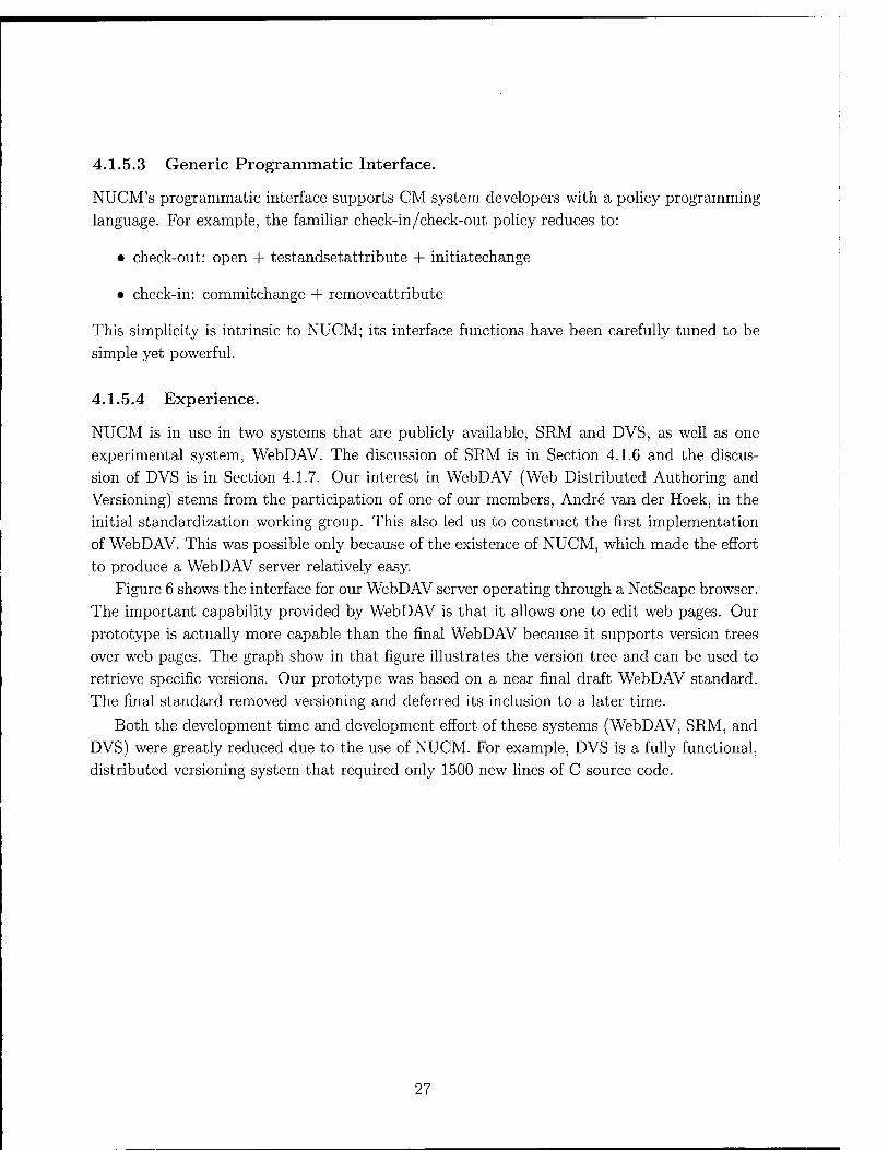
4.1.5.3 Generic Programmatic Interface.
NUCM's programmatic interface supports CM system developers with a policy programming
language. For example, the familiar check-in/check-out policy reduces to:
• check-out: open + testandsetattribute + initiatechange
• check-in: commitchange + removeattribute
This simplicity is intrinsic to NUCM; its interface functions have been carefully tuned to be
simple yet powerful.
4.1.5.4 Experience.
NUCM is in use in two systems that are publicly available, SRM and DVS, as well as one
experimental system, WebDAV. The discussion of SRM is in Section 4.1.6 and the discus-
sion of DVS is in Section 4.1.7. Our interest in WebDAV (Web Distributed Authoring and
Versioning) stems from the participation of one of our members, Andre van der Hoek, in the
initial standardization working group. This also led us to construct the first implementation
of WebDAV. This was possible only because of the existence of NUCM, which made the effort
to produce a WebDAV server relatively easy.
Figure 6 shows the interface for our WebDAV server operating through a NetScape browser.
The important capability provided by WebDAV is that it allows one to edit web pages. Our
prototype is actually more capable than the final WebDAV because it supports version trees
over web pages. The graph show in that figure illustrates the version tree and can be used to
retrieve specific versions. Our prototype was based on a near final draft WebDAV standard.
The final standard removed versioning and deferred its inclusion to a later time.
Both the development time and development effort of these systems (WebDAV, SRM, and
DVS) were greatly reduced due to the use of NUCM. For example, DVS is a fully functional,
distributed versioning system that required only 1500 new lines of C source code.
27

Hie Edit View Go Bookmarks Options Directory Window Help
Bäckj rorwanl| Home Reload| üxtil images! Open,..| Pflnt..| H
Uwatton*! J,ttpj://3^x3.:: ag . Colorado ,■,eduil9717! [
PE
CU-SERL WebPAVInterface
ProJectURl: | ittp://ser[,cs,colorado,edu:1971/project |
Project Document«/ {m^gfgrg » TT;-^ gf ^^ET
Version Tree Document.: <A HREF-"../../cgi/olla/goho
<HR>
- End of Header Button cojj
<CENTER> <IMC SRC-"image1Iglf ALT-'s </H1X/CENTER> r «XENTERXIMG SRC-"yellow'!,'
<H3>Composers</H3XP> <UL>
Show | ShowVersionl Check Out I Check In
Status: |m! version 1.1,1,rchecked;out.,„,
Applet WebDAV running,'
Figure 6: NUCM WebDAV Browser Interface.
28

4.1.6 SRM
Software release management is the process through which software is made available to and
obtained by its users. Complicating software release management is the increasing tendency
for software to be constructed as a "system of systems", assembled from pre-existing, in-
dependently produced, and independently released systems. In these situations, accurately
managing dependencies among the systems is critical to the successful deployment of the
system of systems. Software Release Manager (SRM) is a tool that addresses the software release manage-
ment challenge. It supports the release of systems of systems from multiple, geographically
distributed organizations. In particular, SRM tracks dependency information to automate and
optimize the retrieval of components. Both developers and users of software systems are sup-
ported by SRM. Developers are supported by a simple release process that hides distribution.
Users are supported by a simple retrieval process that allows the retrieval, via the Web, of a
system of systems in a single step and as a single package.
SRM provides the following benefits to an organization:
• Process automation. SRM incorporates and enforces a standard and fully automated
release process.
• Consistency. Users always receive a consistent system of systems.
• Flexibility. SRM supports multiple release tracks, each with its own set of users that
have access to its releases.
• Scalability. SRM can be configured to support an arbitrary number of cooperating
organizations.
• Web integration. Software that is available on the Web from "non-SRM" organizations
is integrated by SRM.
• Uniformity. All releases from all organizations can be released via the same mechanism.
•
•
Evolvability. SRM's flexible dependency mechanism supports the evolution of software through multiple versions, each potentially with different dependencies.
Because of its versatility, SRM serves many different settings:
An organization uses SRM as its release mechanism of choice to publish software on
the Web. Various release groups are set up to distinguish alpha, beta, and production
releases.
An organization uses SRM as an intermediary between CM systems. For example, one
department might use the Process Configuration Management System (PCMS), whereas another one uses the Revision Control System (RCS). SRM can be used to ship and track updates that are sent back and forth.
29

|l£i mit*ewp*' srnU) s*S'ffc**w»i| Hnlp
eis .■■i«i,i -b-i c^a ifi w." i^v-i* * «"i-.^'! ;>! !Q:
1 Bock RJPWBWI «itwiö .■...Hon» VöMK».' *(&**»#'■ '■. .'WW'.
9£Hfc tflWw*r«
'SLfl K)'B&iüiWI Srt:*ft" CiiläHKl SU*
" ->;BifcÜ^ \ & iß(V ja tsn11*.ft»>as C afcs^^iS*! ^Sfs»^ f.
; ;v;B"h-i^ :»is? A?t ?Ji.f*:ij s«,Pr'<t.'(r's?r:,J*aW-l^^3r*Ti^-Ti '"
; >;DvT i:: t«f**j**.iw> :jr«-
■ :<.:tV3 ;t :s IJ-'^T.S^^ä ::&- NiiKiBSNiyx.ti;. j ' : 'i:i:^r ii s.i-viVA'iSJjf« bs-
;v!rv% jM.U^'Mw''^ ■"■■• läftiiLJiiifiiü^rt:.
' :,:»,<« -2n '->?■
v-Ü^M ft.l| Ö?. &&, farrxtwn'nwyfir-azr-r
"WW. -Kl? Ü- ; &* :S(i7*-;t<v!»;w;b;-vtf:ah»i>'
■ 'v'.t: 12 Ö ;iii^ ■ij <^if ?Lti''*"J* !*^(LÄ<öi yö'i'f'iiEtf Kl!
>^ ;a? ^
: ^v.,e iäi. 3:<. %,m ^i'^i'iß^i^'O^öi'fna-ßs
; ;v> ;>sr< jßi-
jJ'^wP.^* ftf r Ä*rhiiir.,^ri| t : 1 ! „. .,.. 1 : 1
— -"■ ~~.~~ }
■t» äI*I ra \*4
Figure 7: SRM Client Download Interface (using Netscape).
• A group of loosely coupled organizations uses SRM as its unifying release mechanism of choice. A single server is placed at one of the organizations to which all other organiza- tions release their software using an SRM client.
• A group of tightly cooperating, geographically dispersed organizations uses SRM to release their software both to the other organizations as well as to the outside world. Each organization maintains its own SRM server, but all SRM servers cooperate to present users with a single view.
4.1.6.1 Prototype.
The SRM prototype presents two interfaces to the world. Figure 7 is the interface presented to users wishing to obtain software from an SRM repository. The interface is actually a web page produced by SRM as a cgi-bin script. This initial page shows all of the systems available for download through SRM. The user checks a system and pushes the button at the bottom.
SRM provides a second web page, shown in Figure 8, that provides information about the chosen system. Figure 9 shows other systems upon which the chosen system depends. The set of dependencies is shown both graphically and in a list of user choosable items. The user is offered the option of:
30
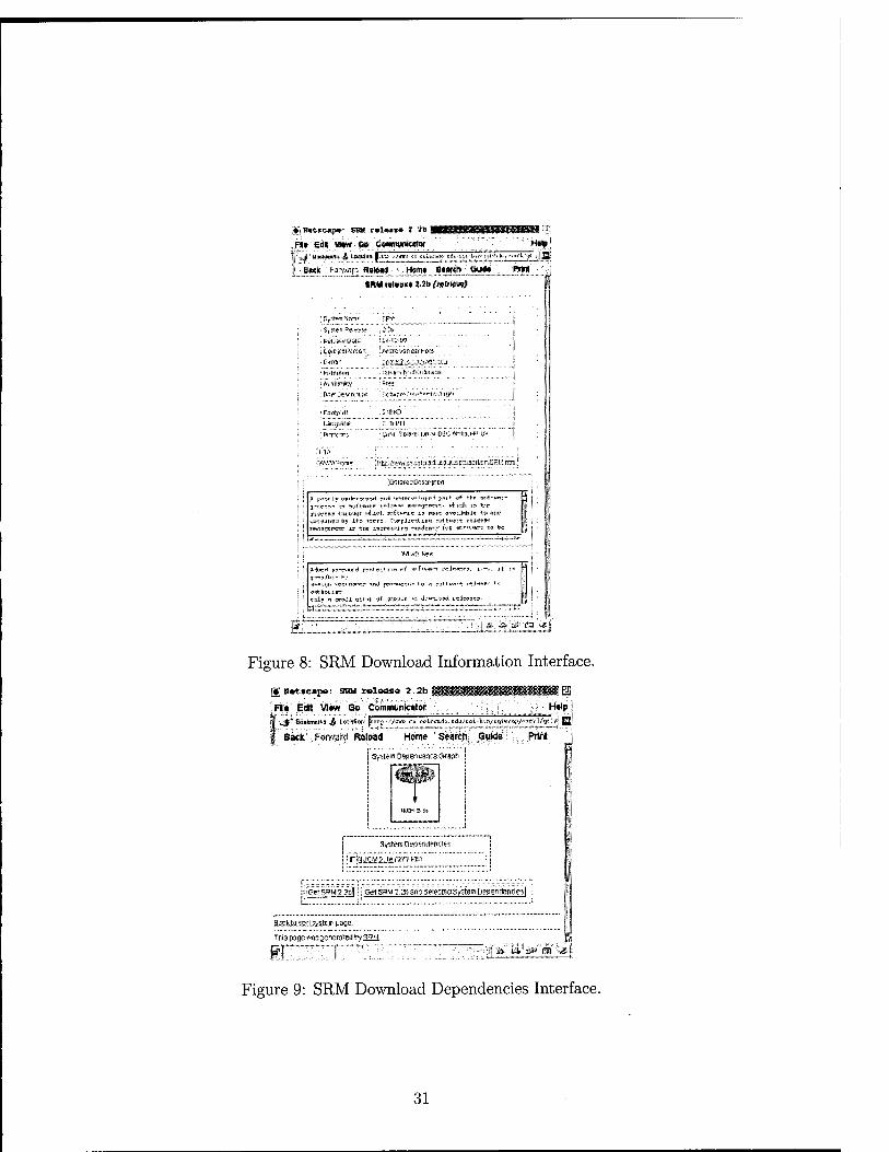
:«•*■!
^HKMi»tA;J6.t8Bii** Jf.iw- «««<! uliCär*;- sit^i-fa^i^-i^-j^V^ /| iQj
«it ' l^arvMiia RsiWtf ; ' HOfM . 6l#«ft - WÜ .. 'WW' ■"
CUM ttlväK* 12b ftfft rtw£ 1
i 'T.t'irtTÜTn^ ■■&•<*
> S(ii*n: ®tz'?H i-^Zit I ': i KiiA;ii-D;4K ; w<-?«=■■!*? ^
\ \'iisCr.tl\H(t\ J.fsfdTiv-SftaSi'UXg*
J ; c-rt» < x aasäiicctaa^ißj - 'fcniiutim .UnvmJvsJOaitfam
i ;A-.:J*>1^' :rr*;
i ff^fC*r*: «;•*;>" - f^u*?^^?^^*^^** [
• <r$«y«*n ..$!<$& \ ! tl^fp^ä*- C.Vl'tl ji
' KWT-V ' sM^ä. i^^.LnsV.0i'v-,i*l^.f*= IM if ^
Imwiir«r !at^^.vh-.^^fcr3^^^^c^s:arri'i;f~lit^.;'
j£KtM«i?D<j*:figs*fl r. ( A £«-r U-.Ki*»-tf**!5*i--»H <**!5rvr-.fc>rH ^r*. y* **r .asrtf*«:" 2 yro,**-!" w »l'«»i;r srl;*-^ »ifjypnr:*»:. *tsdh ss* ti«; fiSTüs* Uttiwab >-4iwrl- 5F3t>>^-ic is t»w* vs&^i'iiiK ».w »>■&* «K-fJJiWK bj xtr «rr:> "Bfrfji? ?.*.:.* *i sa+iMSi'S SSA«»»: ß ; ; i rws»«tretfr ir shs ä.*:rtisw.i.r« r«*rfhwrf is; .I»;**V*%7'ü ?*> ts S : ' }
&~ -i^—* .-»Ä-iw™---™. ™^ ™~ ~— -^™ ui^M^-l- i ■ k
*t.ir^»*»K
>^rt p:W«-H P?rt«u^«f «r'-^^frcJ^s-r». ■■■-. n I-« f r^r-.-M- te |
**&***.«*
:r:r'zrrr:rrrri:™r:r J; .P ■>..<*:a.i ■«■->*)
Figure 8: SRM Download Information Interface.
'§] llottcapo: SRM relaoia 4.2b
*FK* Edit Vim» Go Communicator
0 H*lp]
-^* Sankmnrts ^ Location: |V.tr£:,yew cs vclcirajo. eda,-tfli-V.«/Kijiw.-JY./-3e>"i'ty ^ JJi
Back Forward Reload Home ' Search Guide Prtit
i System OepsntienceGraon
System De^eriiiencits
l;jSft5RWZ3c|;' Cf! saw 3 .SI) ana smtggSystem Depengercie?!
2*dau.5sil.>£;.t££ sagt.
Ths page ^asgengrated hy SRM
tf I & a.i:a» savsc»»
Figure 9: SRM Download Dependencies Interface.
31

si SRM nMg g Submit System Release
Modify System Release
Remove System Release
Retrieve System Release
Help
''■"■ßi!t ■■'"'.''
Figure 10: SRM Upload Menu. 1 Modify Syst« Sslaaco |
BJMHI'MIMK
fctttAitNC
&SSM
|iiV*)rf V?fsii«s+3Ct '
-,,,,„_
Fw -|s»*««riPjr»*ii* Vrttmcjw
: ftHtft««*! J'£ ^■-.^^^.^■^^»^«^^.p
: Miwii; pk iTO :.i«.. i.i.,. .«= ^j,i: >«:-J-
;*««4S*JH'Mi* «aft nur* ;«!«**'» *a*oMmaL-- lii&iK-Ui tk« ■
:l^»Mi.V
WMi*
■i*fc* 1 ,■ *-
1 ..!;'.|i i
jw*-wMfc^m «in» ■ r•■ ■ .[ MiMsbtMn: # *M „£-«* ^ otiNWto |
_ ._ ™.„,„„™„r,M..„.„..„„ „„,..._ _v,.j..- ■
ft[***s»-T'#». * i*t«tfy*%»* , fiwvf>*f*M*wj
. MMrniMl«rltltU"f^
Figure 11: SRM Upload Interface. Hf] Modify Vyst«* Dependencies |
I'flwr :-SiWS. , [JEWS
on
tt «t MtJMB dHpMdwt'
; '-t-i*Z ■ '11 3.Mirw<^.»6 , _, .. ..,
* 1*
:Dc-oa7iM7[ it t™«i»'i.t. ri-.- s^.i« ;QS-0£-66 'rJtvtiMitKKiii<»'ite«lytM *)■»*•*-
Si»tn.Vi*»d wiajOTino of artiftwt» «nd Sist«ijtit*tl iwToicninoiof artifctct» «id
i**rifcrt*<i. .««»icni-it« rf artifact* «nd ©l^WltruVe'Awmwinä ef «ruMAC* anfl
; ;iir$$*$!«i' ^{MM!^^
Figure 12: SRM Upload Dependency Selection Interface.
32
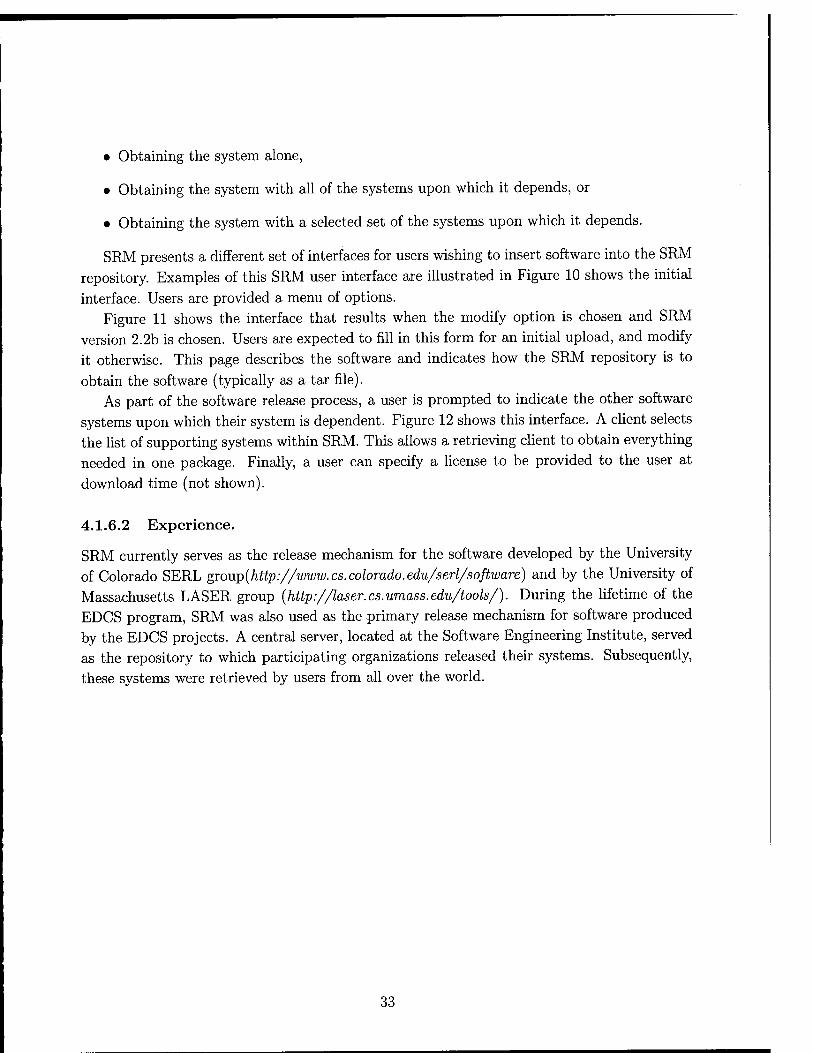
• Obtaining the system alone,
• Obtaining the system with all of the systems upon which it depends, or
• Obtaining the system with a selected set of the systems upon which it depends.
SRM presents a different set of interfaces for users wishing to insert software into the SRM repository. Examples of this SRM user interface are illustrated in Figure 10 shows the initial interface. Users are provided a menu of options.
Figure 11 shows the interface that results when the modify option is chosen and SRM version 2.2b is chosen. Users are expected to fill in this form for an initial upload, and modify it otherwise. This page describes the software and indicates how the SRM repository is to obtain the software (typically as a tar file).
As part of the software release process, a user is prompted to indicate the other software systems upon which their system is dependent. Figure 12 shows this interface. A client selects the list of supporting systems within SRM. This allows a retrieving client to obtain everything needed in one package. Finally, a user can specify a license to be provided to the user at download time (not shown).
4.1.6.2 Experience.
SRM currently serves as the release mechanism for the software developed by the University of Colorado SERL gxo\vp(http://www. cs.colorado.edu/serl/software) and by the University of Massachusetts LASER group (http://laser.cs.umass.edu/tools/). During the lifetime of the EDCS program, SRM was also used as the primary release mechanism for software produced by the EDCS projects. A central server, located at the Software Engineering Institute, served as the repository to which participating organizations released their systems. Subsequently, these systems were retrieved by users from all over the world.
33

4.1.7 DVS
The Distributed Versioning System (DVS) is a revision control system supporting distributed
authoring and versioning of documents with complex structure. It supports multiple developers
at multiple sites over the Internet. DVS differs from most other systems in allowing each
document to be located at a different site, but shared and modified by users at all sites. The Distributed Versioning System is implemented on top of NUCM (Section 4.1.5), which
allows DVS to be very light-weight. This is in contrast to existing commercial systems that
have similar properties, but which are costly and bulky to install. In particular, DVS's physical
repositories (below) are realized by NUCM servers, while the NUCM library provides basic
access to artifacts, workspace management, and distribution.
The architecture of DVS (Figure 13) is composed of one logical repository and one or more
workspaces. The logical repository contains artifacts that are under configuration manage-
ment. Internally, the logical repository is realized by one or more physical repositories. A
workspace is a per-user environment in which artifacts can be viewed, copied, and changed. DVS regulates the interactions between a workspace and the logical repository, for example, by checking in and out artifacts.
The data model implemented by DVS is an extension of the underlying NUCM model (see Section 4.1.5 and Figure 5). It provides a distributed, versioned file system with links and attributes. DVS models artifacts as files and collections of artifacts as directories. Similar to a file system, collections (directories) can contain both artifacts (files) and other collections.
Again, similar to a file system, DVS supports links between collections and artifacts, so that the same artifact can be referenced in any number of collections.
NUCM itself specifies no specific versioning policy. So a major part of DVS is concerned
with the definition and implementation of such a specific versioning policy. In this case, DVS
implements simple linear versioning with versions numbered 1, 2, etc. The DVS versioning
schema is orthogonal to the data model. In DVS, artifacts as well as collections can have
versions. The versioning schema is also completely independent of the relationships occurring
between artifacts and collections. Two different versions of a collection can contain different
versions of the same artifacts and/or completely different artifacts.
The mapping between the logical repository and the physical storage can be arbitrarily
customized at the level of granularity of the single artifact. In other words, every artifact can
be stored in a different repository, allowing the author to exploit "locality" by storing each
artifact closer to the main author or the person that will access it most frequently.
4.1.7.1 Prototype.
DVS consists of thirteen basic commands: co, ci, close, link, unlink, lock, unlock, list, log, setlog, printlocks, whatsnew, sync.
Most DVS commands can operate recursively following either the structure of the
workspace or the structure of collections in the repository. The command co and ci respec-
34

DVS client
Figure 13: DVS Architecture.
tively check out and check in versioned entities. Both co and ci can be applied to artifacts and collections. The co command can optionally lock a file and open it for change provided no one else holds the lock. The ci command requires that the file be currently checked out for change. Locks on artifacts can be directly acquired or released with lock and unlock. When inserting a new artifact with ci, an implicit link is also created with the current working collection. The link and unlink commands explicitly create and remove links between artifacts and collections.
When storing and retrieving artifacts to and from the repository, DVS records some meta- data together with each artifact or collection. Typically, a version log is maintained for each artifact, log, setlog, printlocks, and list are used to access those meta-data.
Besides the basic access and data model manipulation functions, DVS provides a set of utility services that facilitate distributed cooperation. They are whatsnew and sync. The whatsnew command informs a user of new revisions of artifacts and the sync command brings the content of the workspace up to date with respect to the content of the repository.
4.1.7.2 Experience.
Originally, the purpose of DVS was to validate the NUCM approach, but now it is in regular use by SERL for distributed document development. DVS has also been used in several authoring efforts involving people from up to five sites distributed across the United States.
35
4.1.8 Software Dock
The connectivity of large networks, such as the Internet, is affecting how software deployment
is being performed. The simple notion of providing a complete installation procedure for
a software system on a CD-ROM is giving way to a more sophisticated notion of ongoing
cooperation and negotiation among software producers and consumers. This connectivity and
cooperation allows software producers to offer their customers high-level deployment services
that were previously not possible. In the past, only software system installation was widely
supported, but already support for the update process is becoming more common. Support
for other software deployment processes, though, is still virtually non-existent.
New software deployment technologies are necessary if software producers are expected to
accept more responsibility for the long-term operation of their software systems. In order to
support software deployment, new deployment technologies must:
• operate on a variety of platforms and network environments, ranging from single sites to the entire Internet,
• provide a semantic model for describing a wide range of software systems in order to facilitate some level of software deployment process automation,
• provide a semantic model of target sites for deployment in order to describe the context in which deployment processes occur, and
• provide decentralized control for both software producers and consumers.
The Software Dock [17, 19, 20, 22, 29, 36] research project addresses many of these con-
cerns. The Software Dock is a system of loosely coupled, cooperating, distributed components.
The Software Dock supports software producers by providing the release dock that acts as a repository of software system releases. At the heart of the release dock is a standard semantic
schema for describing the deployment requirements of software systems. The field dock compo-
nent of the Software Dock supports the consumer by providing an interface to the consumer's resources, configuration, and deployed software systems. The Software Dock employs agents
that travel from release docks to field docks in order to perform specific software deployment
tasks while docked at a field dock. The agents perform their tasks by interpreting the se- mantic descriptions of both the software systems and the target consumer site. A wide-area
event system connects release docks to field docks and enables asynchronous, bi-directional connectivity.
4.1.8.1 Software Deployment Life Cycle.
In the past, software deployment was largely defined as the installation of a software system; a
view of software deployment that is simplistic and incomplete. Software deployment is actually
a collection of interrelated activities that form the software deployment life cycle. This life
36
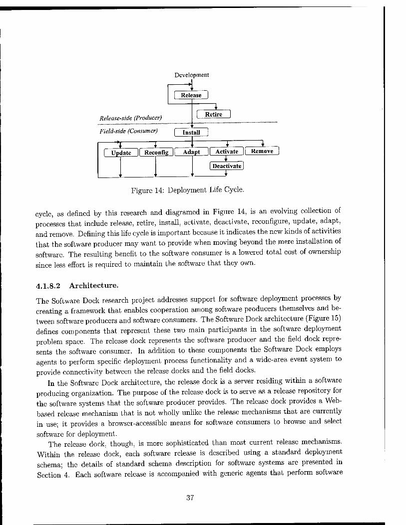
Develc pment
ase | ( Rele
1
Release-side (Producer) [ Retire ]
1 i '
Field-side (Consumer) Install j
'I I 1 1 f Update |( Reconfig )( Adapt j| Activate || Remove j
< ' i
1 [ Deactivate)
Figure 14: Deployment Life Cycle.
cycle, as defined by this research and diagramed in Figure 14, is an evolving collection of
processes that include release, retire, install, activate, deactivate, reconfigure, update, adapt,
and remove. Defining this life cycle is important because it indicates the new kinds of activities
that the software producer may want to provide when moving beyond the mere installation of
software. The resulting benefit to the software consumer is a lowered total cost of ownership
since less effort is required to maintain the software that they own.
4.1.8.2 Architecture.
The Software Dock research project addresses support for software deployment processes by
creating a framework that enables cooperation among software producers themselves and be-
tween software producers and software consumers. The Software Dock architecture (Figure 15)
defines components that represent these two main participants in the software deployment
problem space. The release dock represents the software producer and the field dock repre-
sents the software consumer. In addition to these components the Software Dock employs
agents to perform specific deployment process functionality and a wide-area event system to
provide connectivity between the release docks and the field docks.
In the Software Dock architecture, the release dock is a server residing within a software
producing organization. The purpose of the release dock is to serve as a release repository for
the software systems that the software producer provides. The release dock provides a Web-
based release mechanism that is not wholly unlike the release mechanisms that are currently in use; it provides a browser-accessible means for software consumers to browse and select
software for deployment. The release dock, though, is more sophisticated than most current release mechanisms.
Within the release dock, each software release is described using a standard deployment
schema; the details of standard schema description for software systems are presented in
Section 4. Each software release is accompanied with generic agents that perform software
37

Release docks represent the producer and are a repository of software releases
'-*. Agents provide deployment process functionality _.r>
Wide-area event service provides connectivity
Agent
Agent
Field EH« Dock
Field docks represent the consumer and provide an interface to the consumer site
Figure 15: Software Dock Architecture.
deployment processes by interpreting the description of the software release. The release dock
provides a programmatic interface for agents to access its services and content. Finally, the release dock generates events as changes are made to the software releases that it manages.
Agents associated with deployed software systems can subscribe for these events to receive notifications about specific release-side occurrences, such as the release of an update.
The field dock is a server residing at a software consumer site. The purpose of the field dock
is to serve as an interface to the consumer site. This interface provides information about the
state of the consumer site's resources and configuration; this information provides the context into which software systems from a release dock are deployed. Agents that accompany software
releases "dock" themselves at the target consumer site's field dock. The interface provided by
the field dock is the only interface available to an agent at the underlying consumer site. This
interface includes capabilities to query and examine the resources and configuration of the
consumer site; examples of each might include installed software systems and the operating system configuration.
The release dock and the field dock are very similar components. Each is a server where
agents can "dock" and perform activities. Each manages a standardized, hierarchical registry of information that records the configuration or the contents of its respective sites and cre- ates a common namespace within the framework. The registry model used in each is that of
nested collections of attribute-value pairs, where the nested collections form a hierarchy. Any
change to a registry generates an event that agents may receive in order to perform subse- quent activities. The registry of the release dock mostly provides a list of available software
releases, whereas the registry of the field dock performs the valuable role of providing access to consumer-side information.
Consumer-side information is critical in performing nearly any software deployment pro-
cess. In the past, software deployment was complicated by the fact that consumer-side in-
formation was not available in any standardized fashion. The field dock registry addresses
38

this issue by creating a detailed, standardized, hierarchical schema for describing the state of a particular consumer site. By standardizing the information available within a consumer organization, the field dock creates a common software deployment namespace for accessing consumer-side properties, such as operating system and computing platform. This informa- tion, when combined with the description of a software system, is used to perform specific
software deployment processes. Agents implement the actual software deployment process functionality. When the instal-
lation of a software system is requested on a given consumer site, initially only an agent re- sponsible for installing the specific software system and the description of the specific software system are loaded onto the consumer site from the originating release dock. The installation agent docks at the local field dock and uses the description of the software system and the consumer site state information provided by the field dock to configure the selected software system. When the agent has configured the software system for the specific target consumer site, it requests from its release dock the precise set of artifacts that correspond to the software
system configuration. The installation agent may request other agents from its release dock to come and dock
at the local field dock. These other agents are responsible for other deployment activities such as update, adapt, reconfigure, and remove. Each agent performs its associated process by interpreting the information of the software system description and the consumer site
configuration. The wide-area event service in the Software Dock architecture provides a means of connec-
tivity between software producers and consumers for "push"-style capabilities. Agents that are docked at remote field docks can subscribe for events from release docks and can then perform actions in response to those events, such as performing an update. Siena (Section 4.1.9) is currently used for event notification in the Software Dock. In addition to event notification, direct communication between agents and release docks is supported and provided by standard protocols over the Internet. Both forms of connectivity (events and direct messages) combine to provide the software producer and consumer the opportunity to cooperate in their pursuit of software deployment process support.
4.1.8.3 Deployable Software Description.
In order to automate or simplify software deployment processes it is necessary to have some form of deployment knowledge about the software system being deployed. One approach to this requirement is the use of a standardized language or schema for describing a software system; this is the approach adopted by the Software Dock research project. In such a language or schema approach it is common to model software systems as collections of properties, where semantic information is mapped into standardized properties and values.
The Software Dock project has defined the Deployable Software Description (DSD) format to represent its system knowledge. The DSD is a critical piece of the Software Dock research
39

•
•
•
project that enables the creation of generic deployment process definitions. The DSD provides
a standard schema for describing a software system family. In this usage, a family is defined as
all revisions and variants of a specific software system. The software system family was chosen
as the unit of description, rather than a single revision, variant, or some combination, because
it provides flexibility when specifying dependencies, enables description reuse, and provides
characteristics, such as extending revision lifetime, that are necessary in component-based development.
We have identified five classes of semantic information that must be described by the software system model. These classes of semantic information are:
Configuration - describes relationships inherent in the software system, such as revi-
sions and variants, and describes resources provided by the software system, such as
deployment-related interfaces and services.
Assertions - describe constraints on consumer-side properties that must be true otherwise
the specific deployment process fails, such as supported hardware platforms or operating systems.
Dependencies - describe constraints on consumer-side properties where a resolution is possible if the constraint is not true, such as installing dependent subsystems or recon- figuring operating system parameters.
Artifacts - describe the actual physical artifacts that comprise the software system.
Activities - describe any specialized activities that are outside of the purview of standard software deployment processes.
A DSD family description is broken into multiple elements that address the five semantic
classes of information. The sections of a DSD family description are identification, imported
properties, system properties, property composition, assertions, dependencies, artifacts, in- terfaces, notifications, services, and activities. Some of these sections map directly onto the
five semantic classes of information, others, such as system properties, property composition,
interfaces, and notifications, combine to map onto the configuration class of semantic infor-
mation. For more information about the DSD, refer to publications [19], [20], [22], and [36] in Section 6.
4.1.8.4 Enterprise Software Deployment.
Enterprise software deployment extends the current single site software deployment to the
problem of managing the integrity of software systems on many sites throughout an organi-
zation. This extension requires that enterprise software deployment deal with issues of scale,
distribution, coordination, and heterogeneity The low-level details of the various software
40
•
deployment life cycle processes are therefore not the focus of enterprise software deployment;
the focus is coordinating and managing deployment processes across multiple sites.
For example, installing a software system on a thousand sites reveals issues that are not
present when installing the same software system on a single site. Complications arise due
to the necessity to consider policy decisions, such as ad hoc, phased-in, or all-or-nothing
installation. Also, heterogeneity issues are very important when dealing with a large number
of sites since the software deployment processes depend heavily on the precise configuration
of a site's hardware, operating system, and resources. In order to provide a solution for enterprise software deployment, it is necessary for a
symbiotic relationship to exist between standard software deployment and enterprise software
deployment. Enterprise software deployment must build on top of a standard software deploy-
ment solution. The current Software Dock prototype provides limited support for enterprise
level operation (see the Admin Workbench discussion below); it remains an ongoing research
topic.
4.1.8.5 Prototype.
The current Software Dock implementation includes a field dock, a release dock, and a collec-
tion of generic agents for performing the install, update, adapt, and removal of DSD described software systems. Additional tools, such as the Schema Editor for creating DSD descriptions
and the Docking Station for managing software at a field dock, are also provided. The Software
Dock is implemented entirely in Java and uses the remote procedure call and agent capabilities
of ObjectSpace's Voyager, which is also completely Java-based. The prototype of the Software Dock provides the primary field dock interface shown in
Figure 16. From this interface, a user at the field dock can carry out various life cycle activities including install of a new system and update, reconfigure, adapt, or remove of a previously
installed system. Most of these activities involve specifying various properties of the system.
Figure 17 shows the interface to the generic mechanism for defining or modify the properties
associated with a system. Enterprise level operations are represented by the Admin(istrator) Workbench shown in
Figure 18. The Admin Workbench provides an entry point for software administrators to
monitor the result of deployment activities on managed sites, as well as, to perform remote
operations such as taking an inventory or pushing updates or reconfigurations. This interface is still experimental since the set of enterprise-level operations is still in flux.
This current interface allows an administrator to do a variety of things.
• Monitor the activities of field docks,
• Take inventory of the systems installed at one or more field docks,
• Force reconfigurations, removals, updates, and adaptations upon one or more field docks.
41

EU Docking Station
Example ir
Property HTMLHelp Help WinHelp
Value true true false
[a «D
d Software
I Dock Figure 16: Field Dock Main Interface.
Confiq Editoi
Example ^2 Version
I r Select any J '-
;| Templates for 1.2 13
Import Filters f»l i- Select any ■- — -
MS Word B rSelBct one - -■'
MS Word 97 0
j I MS Word 95 D | MS Word 6.0 Q
j HTML 0
WordPerfect D
{Spell Checker iß
JGrammar Checker 63
(Single User
: Owner Cache Size
Joe User 5.95
Enabled ▼
Okayj Cancel
Figure 17: Field Dock Property Manipulation Interface.
Els Admin Workbench
-Monitor——
H {nstallj
E Update
IE Reconfigure
DAdapt
IE Remove
Ö5E
[yi Inventory [^Update
\$ Reconfigure © Adapt
|^ Remove |p Constrain
Figure 18: Enterprise-level Administrators Workbench Interface.
42

Software Dock InstallShield
Install 172.0s 168.0s Remove 36.7s 80.0s Reconfig (remove) 40.3s 90.0s Reconfig (add) 113.3s 284.3s Update 187.3s 149.6s
Table 1: Software Dock Performance Comparison.
• Enforce constraints on allowable configurations upon field docks.
Note that the communication between the administrator and the field docks and release docks
is provided by Siena (Section 4.1.9).
4.1.8.6 Experience.
The current implementation was used in two joint demonstrations with Lockheed Martin Corporation at several of the EDCS "Demo Days" activities.
The first demonstration used a Web-based software system called the Online Learning Academy (OLLA), which consisted of 45 megabytes of data and software in over 1700 files. OLLA was comprised of two dependent subsystems called Disco and Harvest. The software de- ployment processes of release, install, reconfigure, update, adapt, and remove were all initially demonstrated using the generic agents along with the DSD description of all three software
systems. The Second demonstration involved the use of the Software Dock with the Lockheed
EVOLVER project and was demonstrated at the Baltimore Demo Days meeting. A core tech- nology of EVOLVER was a KQML-based mechanism for wrapping information sources and making them available through the EVOLVER infrastructure. This involved two steps. First, an information source was made available in a simple form by providing a KQML wrapper. The second step require that the wrapped information source also export meta-information that allowed EVOLVER to infer connections between the information source and other sources available through EVOLVER.
We obtained an early release of the Java-based KQML wrapper system from Lockheed Martin, and we applied it to the Software Dock to make the Dock's repository of configuration information available through EVOLVER. Although there were some problems, the integration was successfully completed. The biggest hurdle was to map between the Software Dock's data model and the EVOLVER data model.
Experiments were also conducted to verify the performance of the Software Dock. These experiments compared the Software Dock prototype to an existing deployment solution (i.e., InstallShield) for a specific software system. A DSD specification for versions 1.1.6 and 1.1.7 of the Java Development Kit (JDK) by Sun Microsystems was created in order to compare the Software Dock deployment processes to the standard InstallShield self-extracting distribution
43

archive for the Microsoft Windows platform. Time to completion was the dimension for comparison. Table 1 summarizes the results of the experiments.
The Software Dock performed as well or better than InstallShield in most cases, despite the fact that file artifacts were dynamically packaged for the specific configuration requests. This dynamicity was most obvious in the update process. The comparison is strained in the case of update and reconfigure because standard InstallShield package for JDK does not properly perform these activities, and it does not perform adapts at all.
44

4.1.9 Siena
There is a clear trend among experienced software developers toward designing large-scale
distributed systems as assemblies of loosely-coupled autonomous components; a trend that
was evident in EDCS especially One approach to achieving loose coupling is an event-based
or implicit invocation design style. In an event-based system, component interactions are
modeled as asynchronous occurrences of, and responses to, events. To inform other components
about the occurrences of internal events (such as state changes), components emit notifications
containing information about the events. Upon receiving notifications, other components can
react by performing actions that, in turn, may result in the occurrence of other events and the
generation of additional notifications. Several classes of applications make use of some sort of event service. Examples of such
applications are monitoring systems, user interfaces, integrated software development envi-
ronments, active databases, software deployment systems, content distribution, and financial
market analysis. Many of these applications are also inherently distributed, and thus they
require interaction among components running on different sites and possibly distributed over
a wide-area network. Wide-area networks such as the Internet, with their vast number of potential producers and
consumers of notifications, create an opportunity for developing novel distributed event-based
applications in such fields as market analysis, data mining, indexing, and security. In general,
the asynchrony, heterogeneity, and inherent high degree of loose coupling that characterize
applications for wide-area networks suggest event interaction as a natural design abstraction
for a growing class of distributed systems. Yet to date there has been a lack of sufficiently
powerful and scalable middleware infrastructures to support event-based interaction in a wide- area network. We refer to such a middleware infrastructure as an event notification service.
Siena [4, 6, 9, 15, 25] is our prototype Internet-scale event notification service that is
representative of the capabilities we envision for scalable event notification middleware. Siena
is designed to be a ubiquitous service accessible from every site on a wide-area network.
4.1.9.1 Architecture
As shown in Figure 19, Siena is implemented as a distributed network of servers that provide
clients with access points offering an extended publish/subscribe interface. The clients are of
two kinds: objects of interest, which are the generators of notifications, and interested parties,
which are the consumers of notifications; of course, a client can act as both an object of in-
terest and an interested party. Clients use the access points of their local servers to publish
their notifications. Clients also use the access points to subscribe for individual notifications
or compound patterns of notifications of interest. Siena is responsible for selecting the notifi-
cations that are of interest to clients and then delivering those notifications to the clients via
the access points.
45

Figure 19: Distributed Event Notification Service.
Siena is a best-effort service in that it does not attempt to prevent race conditions induced by network latency. This is a pragmatic concession to the realities of Internet-scale services, but it means that clients of Siena must be resilient to such race conditions. For instance, clients must allow for the possibility of receiving a notification for a cancelled subscription. Of
course, an implementation would likely adopt techniques such as persistent data structures,
transactional updates to the data structures, and reliable communication protocols to enhance the robustness of this best-effort service.
The key design challenge faced by Siena is maximizing expressiveness in the selection mechanism without sacrificing scalability of the delivery mechanism. The scalability problem can be characterized by the following dimensions:
• large number of objects publishing events and subscribing for notifications,
• large number of events,
• high event generation rates,
• objects distributed over a wide-area network (thus, low bandwidth, scarce connectivity and reliability),
• events of the same class generated by many different objects,
• notifications of the same class of events requested by many objects,
• no centralized control nor global view of the structure of the event service.
Expressiveness refers to the power of the data model that is offered to publishers and
subscribers of notifications. Clearly the level of expressiveness influences the algorithms used to route and deliver notifications, and the extent to which those algorithms can be optimized. As
46

Notification
Event = /economy/exchange/stock Exchange= NASDAQ Stock MSFT Price $2.34 Diff + 1.2 % Date 1998 Jul 22 10:30:01 MST Quantity= 4321
Figure 20: Siena Event Notification Example.
Filter "^\
Exchange= NASDAQ Stock = MSFT Price > $2.34 Diff > + 0.5 %
Figure 21: Siena Event Filter Example.
the power of the data model increases, so does the complexity of the algorithms. Therefore, the
expressiveness of the data model ultimately influences the scalability of the implementation,
and hence scalability and expressiveness are two conflicting goals that must be traded off.
While we have not fully explored the nature of this tradeoff, we have investigated a number
of carefully chosen points in the tradeoff space. In particular, we designed a data model
for Siena that we believe is sufficiently expressive for a wide range of applications while still
allowing sufficient scalability of the delivery mechanism. Based on this data model, we designed distributed server architectures and associated delivery algorithms and processing strategies,
and we evaluated and confirmed their scalability.
4.1.9.2 Interface
The interface of the Siena event service allows objects to subscribe for specific classes of events,
by setting up filters, or for specific sequences of events, by setting up patterns. Filters select events based on their content using a simple and yet powerful query language. Patterns are
combinations of filters that select temporal sequences of events. Siena provides a flexible notification model that can serve application programmers as
well as end users. Event notifications (Figure 20) are structured as a set of attributes. Each
attribute has a name, a type, and a value.
47

d ö Figure 22: Hierarchical Routing Example.
Event filters (Figure 21) are structured as a set of simple relations. Each relation is an attribute name, an operator, and a constant value.
4.1.9.3 Routing Optimization
Siena delivers a scalable event service by adopting special dispatching protocols that aim at reducing network traffic and avoiding bottlenecks.
Depending on the topology of connections among Siena servers, hierarchical or peer-to-
peer, different algorithms have been implemented to deliver notifications. These are based
on the propagation of subscriptions (subscription forwarding) or on the propagation of adver-
tisements (advertisements forwarding). These two algorithms also roughly correspond to the main strategies that Siena applies in filtering and multicasting notifications:
• upstream filtering and assembly: filters and patterns are pushed as close as possible to
the sources of events, thereby immediately pruning the propagation of notifications that are not requested by any object.
• downstream replication: replication of notifications (multicasting) is pulled as close as
possible to the targets of notifications. The idea being that, in order for a notification
to reach several objects on distant networks, only one copy of that notification needs to
traverse slow internetwork paths. That notification is then replicated and routed to all its destinations only when it gets to their local (less expensive) network.
Figure 22 illustrates an example of hierarchical routing in Siena.
4.1.9.4 Experience.
The design of Internet-scale systems requires a special effort for validation. In particular, it is
important to assess the impact of routing strategies and event pattern recognition with respect
48

to costs such as network traffic, CPU, and memory usage. The architectures of Siena and its routing algorithms were studied by means of systematic
simulations in various network scenarios with different ranges of loads and different configu-
rations. Currently, a prototype of Siena is used as wide-area messaging and event system of the
Software Dock. There are two main implementations of the Siena server. One (written in Java) realizes a hierarchical server, while the other (written in C++) has a peer-to-peer architecture. The client interface is currently available for both Java and C++.
49

4.1.10 Aladdin
Aladdin is a tool for analyzing intercomponent dependencies in software architectures. It
can statically check formal specifications of software architectures for certain dependence-
related properties. It can also help localize faults that are the cause of failures discovered
during simulation or other means of validation. Aladdin can detect anomalies such as unused component ports and cycles in dependence relationships among components.
Software architectures model systems at high levels of abstraction. They capture infor-
mation about a system's components and how those components are interconnected. Some
software architectures also capture information about the possible states of components and
about the component behaviors that involve component interaction; behaviors and data ma-
nipulations internal to a component are typically not considered at this level.
Formal software architecture description languages allow one to reason about the correct-
ness of software systems at a correspondingly high level of abstraction. Techniques have been
developed for architecture analysis that can reveal such problems as potential deadlock and component mismatches. In general, there are many kinds of questions one might want to ask
at an architectural level for purposes as varied as reuse, reverse engineering, fault localization, impact analysis, regression testing, and even workspace management. These kinds of ques-
tions are similar to those currently asked at the implementation level and answered through
static dependence analysis techniques applied to program code. It seems reasonable, therefore,
to apply similar techniques at the architectural level, either because the program code may
not exist at the time the question is being asked or because answering the question at the architectural level is more tractable than at the implementation level.
4.1.10.1 Dependence Analysis by Chaining
The aladdin system uses chaining, a dependence analysis technique for software architectures.
In chaining, links represent the direct dependence relationships that exist in an architectural
specification that, when collected together, produce a chain of dependencies that can be fol- lowed during analysis.
The traditional view of dependence analysis is based on control and data flow relationships
associated with functions and variables. Here, a broader view of dependence relationships is
taken that is more appropriate to the concerns of architectures and their attention to compo-
nent interactions. In particular, both the structural and the behavioral relationships among
components expressed in current-day formal architecture description languages, such as Rapide and Wright are considered.
Dependence relationships at the architectural level arise from the connections among com-
ponents and the constraints on their interactions. These relationships may involve some form
of control or data flow, but generally they involve structure and behavior. Examples of struc- tural relationships are
• Includes,
50

• Import/Export,
• and Inheritance.
Examples of behavioral relationships are
• Temporal,
• Causal,
• Input,
• and Output.
Both structural and behavioral dependencies are important to capture and understand
when analyzing an architecture. There are a variety of questions that should be answerable by an examination of a formal architecture description. For example, one might want to ask
the following kinds of questions:
1. Are there any components of the system that are never needed by any other components
of the system?
2. If this component is communicating through a shared repository, with what other com-
ponents does it communicate?
3. If the source specification for a component is checked out into a workspace for modifica-
tion, which other source specifications should also be checked out into that workspace?
4. If a change is made to this component, what other components might be affected?
5. If a change is made to this component, what is the minimal set of test cases that must
be rerun?
6. If a failure of the system occurs, what is the minimal set of components of the system
that must be inspected during the debugging process?
These questions share the theme of identifying the components of a system that either affect or
are affected by a particular component in some way. In chaining, chains represent dependence relationships in an architectural specification. Individual chain-links within a chain associate
components and/or component elements of an architecture that are directly related, while a
chain of dependencies associates components and/or component elements that are indirectly
related. To build a chain one determines a component or element to use as the origin of the chain
and a relationship type that will help answer the question at hand. For instance, if the
analyst is trying to discover why an error message was incorrectly emitted, then the chain
would be constructed based on the event that generates the error message and the caused-by
51
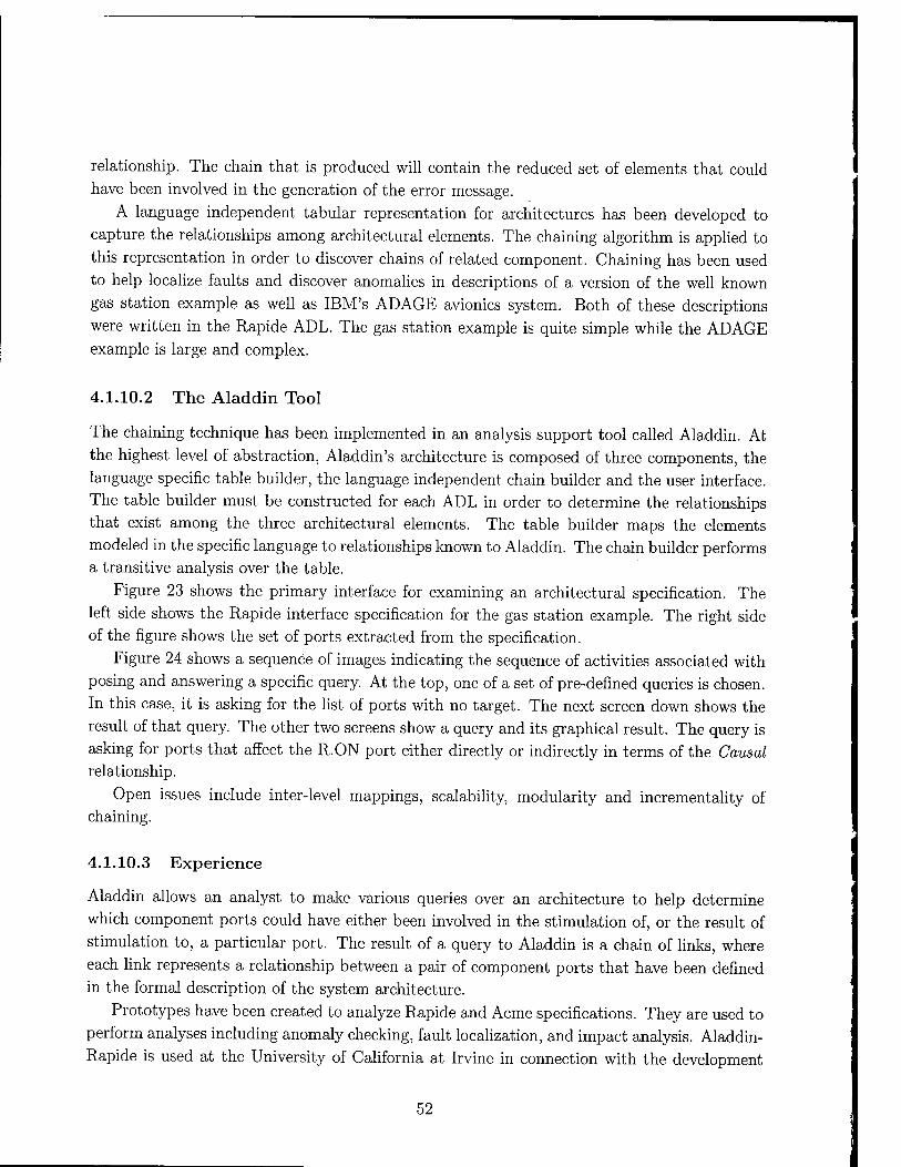
relationship. The chain that is produced will contain the reduced set of elements that could have been involved in the generation of the error message.
A language independent tabular representation for architectures has been developed to
capture the relationships among architectural elements. The chaining algorithm is applied to
this representation in order to discover chains of related component. Chaining has been used
to help localize faults and discover anomalies in descriptions of a version of the well known
gas station example as well as IBM's ADAGE avionics system. Both of these descriptions
were written in the Rapide ADL. The gas station example is quite simple while the ADAGE example is large and complex.
4.1.10.2 The Aladdin Tool
The chaining technique has been implemented in an analysis support tool called Aladdin. At
the highest level of abstraction, Aladdin's architecture is composed of three components, the
language specific table builder, the language independent chain builder and the user interface. The table builder must be constructed for each ADL in order to determine the relationships
that exist among the three architectural elements. The table builder maps the elements modeled in the specific language to relationships known to Aladdin. The chain builder performs a transitive analysis over the table.
Figure 23 shows the primary interface for examining an architectural specification. The left side shows the Rapide interface specification for the gas station example. The right side of the figure shows the set of ports extracted from the specification.
Figure 24 shows a sequence of images indicating the sequence of activities associated with
posing and answering a specific query. At the top, one of a set of pre-defined queries is chosen. In this case, it is asking for the list of ports with no target. The next screen down shows the
result of that query. The other two screens show a query and its graphical result. The query is
asking for ports that affect the R.ON port either directly or indirectly in terms of the Causal relationship.
Open issues include inter-level mappings, scalability, modularity and incrementality of chaining.
4.1.10.3 Experience
Aladdin allows an analyst to make various queries over an architecture to help determine
which component ports could have either been involved in the stimulation of, or the result of
stimulation to, a particular port. The result of a query to Aladdin is a chain of links, where
each link represents a relationship between a pair of component ports that have been defined in the formal description of the system architecture.
Prototypes have been created to analyze Rapide and Acme specifications. They are used to
perform analyses including anomaly checking, fault localization, and impact analysis. Aladdin-
Rapide is used at the University of California at Irvine in connection with the development
52
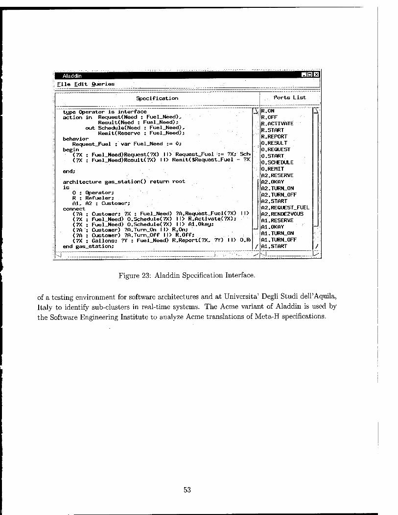
1 Aladdin H0Q| ; File Edit Queries
Specification Ports List
i type Operator is interface A R.ON A action in Request(Need : Fuel_Need), R.OFF
Result(Need : Fuel_Need); R.ACTIVATE out Schedule(Need : Fuel_Need), R.START
R.REPORT Remit(Reserve : Fuel_Need);
behavior | Request_Fuel : var Fuel_Need t= 0; 0.RESULT
begin 0.REQUEST ! (?X : Fuel Need)Request(?X) 1l> Request_Fuel := ?X; Sen. 0.START
(?X : Fuel_Need)Result(?X) 1l> Remit($Request_Fuel - ?X. 0.SCHEDULE
:j end; 10. REMIT A2.RESERVE
architecture gas_station() return root A2.0KAY is IA2.TURN ON
0 : Operator; A2.TURN OFF R : Refueler;
■! Al, A2 : Customer; A2.START connect A2.REQUEST_FUEL
(?A Customer; ?X : Fuel_Need) ?A.Request_Fuel(?X) 1l> A2.RENDEZVOUS (?X Fuel Need) O.Schedule<?X) 1l> R.Activate(?X); Al.RESERVE (?X Fuel_Need) O.Schedule(?X) ll> Al.Okay; Al.OKAY _ (?A Customer) ?A.Turn_0n 1l> R.On; —* <?A Customer) ?A.Turn Off 1l> R.Off; A1.TURN_0N
<?X Gallons; ?Y : Fuel_Need) R.Report(?X, ?Y) 1l> O.R. A1.TURN_0FF end gas_station; / Al.START ■■■/
,-J __. : . . _J- v ^ -4 >■
Figure 23: Aladdin Specification Interface.
of a testing environment for software architectures and at Universita' Degli Studi dell'Aquila, Italy to identify sub-clusters in real-time systems. The Acme variant of Aladdin is used by the Software Engineering Institute to analyze Acme translations of Meta-H specifications.
53

Queries sm Forts with no target Ports with no source
Create chain... Aladdin: Anomalies
Ignored Ports
O.REMIT A2.RESERVE Al.RESERVE
A
Aladdin: Get Query
Port Name(COMPONENT.PORT): |R
Relationship 1
♦ Causal
Query Type
\r Ports directly related t ♦ Ports indirectly affectl v Ports indirectly affecte v Ports related to selecti
OK
^.REQUEST
'-'Causes
R.ON
Figure 24: Aladdin Query Interface.
54

4.1.11 Menage
The Menage project introduces the enhanced notion of configurable software architecture, an
abstraction that seamlessly integrates the traditional view of software architecture with the
configuration management concepts of evolution, variants, and options. Menage is intended to
be used both in the development phase of the traditional software life cycle (during design and
implementation), but also in the post-development life cycle [17] (during installation, update,
and execution). The Menage project had two goals. First, produce a common representation
that could be used to represent configurable architectures in both pre- and post- development
activities. Second, to produce a design tool to allow for the specification of configurable
architectures.
4.1.11.1 Background
Design, implementation, and deployment are three activities that are normally carried out
during the lifetime of a software system. In support of these activities, three distinct software
engineering disciplines have emerged: software architecture, configuration management, and
configurable distributed systems. Software architecture addresses the high-level design of a
system. A system design is partitioned into its primary, coarse grain components. These
components are then combined into a complete system by explicitly modeled connections.
Often, a software architecture description language that formally describes the components and
connections is provided. Configuration management supports the implementation phase of a
software system. Typical solutions manage multiple versions of the source files that implement
a system, provide for a selection mechanism to choose a consistent system configuration out of the version space, and subsequently construct the software system out of the selected source
files. Configurable distributed systems concentrate on managing a system once it is "out in the field". The goal is to reconfigure a system after it has been deployed. In particular,
component updates need to be administered in such a way that consistency of the deployed
system is guaranteed, even in cases where it is required that a system continues executing
while the update takes place. Support for this capability is most often provided by specialized
programming constructs and system configuration managers. Until now the three disciplines have largely evolved separately. However, evidence suggests
that they are intimately related. A first indication is that the disciplines share a certain amount
of terminology. For example, configurable distributed systems and configuration management
share the notion of a configuration that is composed from multiple parts, software architecture
and configurable distributed systems both consider components as the level of granularity, and
all three disciplines share the goal of maintaining a consistent system.
4.1.11.2 Configurable Architecture
Traditional ADLs have not provided any support for configurability. To address this problem,
our previous work has extended the traditional notion of software architecture to also model
55

the following three dimensions that we believe comprise the essence of configurability for active systems.
• Variability refers to the fact that a single software system can provide multiple, alter-
native ways of achieving the same functionality. As an example, consider a numerical optimization system that has been engineered to operate either slow but very precise, or
fast but only approximate. Depending on the desired mode of operation, the selection
of components included in the actual system configuration can be very different.
• Optionality means that a software system has one or more additional parts (and con-
sidered part of the architecture) each of which may or may not be incorporated in the
system. For example, consider the fact that the numerical system can optionally gather
statistics. The source files that implement the gathering and analyzing of the statistics
at run time are only included in the system configuration if the option to gather statistics is turned on.
Evolution is used to capture the notion that a software system changes over time to
provide a related, yet different, set of capabilities. In a configurable architecture sense, evolution may be roughly equated with more traditional revision numbers in that it de- notes some sequence of architectures. Evolution may be equated to the more traditional
notion of a version graph relating specific architectures in terms of the properties that
define them. In the past, these properties have consisted of a single revision number,
but Menage, like the Software Dock, extends the notion of property to capture more complex characteristics of architectures.
Expanding on this last point, our model allows the association of arbitrary properties with
specific components or connections within the software architecture. The resulting abstraction,
configurable software architecture, can be used to precisely control the types of changes that one is allowed to make at run time.
4.1.11.3 Menage Design Tool
A prototype design tool was created to support the specification of configurable architectures. Our representation for configurable software architecture is based on Acme, Darwin, and
PCL, and orthogonally integrates evolution, variants, and options into a single architectural representation. Evolution is supported via the well-known version tree; variants and options
are supported via a property-based specification and selection process. Architectural baselines are captured as configurations and parallel work is facilitated through branching.
Figure 25 shows a screen snapshot of the Menage tool's interface through which particular
configurable software architectures are specified. The top of the figure shows the version tree
depicting the evolution of a specific component named "GlobalOptimization." The center part
of the figure shows the internal architecture of that component in terms of other components and the connections between them.
56

NT l:l< PACKS
a^ v.m '*">>■■■ ''
U:
Figure 25: Menage Design Environment Screen Snapshot.
saaaa [Minima kanouKW Oenam
Figure 26: Variant Architecture of Component Optimizer
Figure 26 shows the specification for a component with more than one variant. The com- ponent is called "optimizer" and it appears as the lower left box in the previous figure. This component has two variants: "slowOpt" and "fastOpt." Depending on the value of a property ("speed"), one of the variants will used in the overall architecture shown in Figure 25.
4.1.11.4 Experience
The Menage prototype was not completed under this project. Development continues at UC, Irvine, where Dr. van der Hoek is now assistant professor. Menage is expected to play an important role in the DASADA program because it has been embedded into xArch, an XML- based architecture language.
57

4.1.12 WIT
The Web Integration Tool (WIT) is a prototype tool for integrating datawebs. The goal of
WIT is to simplify, and to the extent possible, automate the process of selectively integrating
multiple datawebs into a unified dataweb. The resulting structure can then be accessed and
efficiently navigated by collaborators and others using Web resources (and relationships among them) from the combined datawebs.
4.1.12.1 WIT Capabilities
The WIT prototype enables users to rapidly build a unified dataweb by simply supplying
the URLs of existing datawebs to be integrated. WIT-constructed datawebs can be used as
input for further integration with other datawebs, allowing arbitrary numbers of datawebs to be
integrated into a single unified dataweb. Thus, federations of any size can use WIT to construct
unified views of their data. The WIT integration process does not alter the original datawebs
used as input in any way. Instead, WIT creates a new, integrated dataweb based on the
contents of the individual datawebs to be integrated, and writes it to the desired location (i.e., the WIT target host machine). However, WIT can be made to alter existing datawebs when
desired. For example, users of WIT can alternatively elect to merge one dataweb into another.
The merging operation differs from integration in that one of the datawebs is supplemented with information contained in one or more other datawebs.
4.1.12.2 Architecture and Implementation
Because WIT operates on a standardized dataweb architecture, a lightweight implementation
of this integration tool is possible. Our design takes advantage of the heavy lifting (wrap-
pers and query capability) already done by the underlying dataweb management systems and
makes no effort to reinvent them. WIT utilizes Java servlets, user-accessible from a browser,
to compare contents of remote datawebs and create the necessary files and links needed to
provide a unified view of the datawebs of interest. Network connectivity and an HTTP server,
supplemented with a servlet engine, are required by sites using WIT. The integration pro-
cess is completely unobtrusive, disturbing neither the Web-accessible data nor the organizing structure of the datawebs being combined.
WIT Datawebs An early decision required in the design of WIT related to the selection
of a (standardized) data model to use for its dataweb architecture. Adoption of an existing
dataweb management system (and the dataweb architecture it used) helped us to remain
focused solely on the integration aspects of datawebs. We also felt the design and construction
of an integration tool for real, pre-existing datawebs would lend credibility and a degree of validation to any integration tool successfully built upon that dataweb model. After reviewing
existing dataweb information systems, we choose a dataweb architecture used by the Labyrinth system.
58

Without altering original Web resources, Labyrinth's data model supplements each re-
source with a related HTML entity shadow file, a Web page containing links not only to the
original Web resource, but to relationship shadow files (Web pages) as well. These links make
relationships among the original Web resources explicit. In turn, it becomes possible to nav-
igate these datawebs much the same as one would traverse an Entity-Relationship diagram
by traversing the lines connecting entities to relationships. Related Web resources are further
supplemented with directories (Web pages) containing links to all instances of each shadow
file type. At the highest level of dataweb structure, a schema, in the form of a directory of
directories, identifies links to each type of entity and relationship directory. We will use the
term ER-dataweb to refer to datawebs built using a Labyrinth-style architecture.
The Labyrinth system itself is a powerful environment that supports the schema defini-
tion, populating, and browsing of datawebs. A significant difference between Labyrinth and
somewhat similar systems like CARTE or EnLIGHTeN is that Labyrinth incorporates no com-
mercial DBMS to facilitate query processing over large datawebs. This aspect of Labyrinth
further simplies the dataweb integration process.
WIT Implementation The WIT system is comprised of a series of Java servlets that
interact across the network space where the ER-datawebs to be integrated reside. Java servlets
provide a straightforward means of analyzing and navigating the internal structures of ER-
datawebs residing on servers distributed across a network. WIT is capable of retrieving and writing remote and local files and directory listings.
This capability, along with knowledge of the highly standardized architecture of ER-datawebs, enables the servlet to methodically scan each ER-dataweb's content and supporting structures
to create a structured superset of all components encountered. This superset becomes the
integrated ER-dataweb and is written to the WIT host machine specified by the user. WIT servlets can be installed on any host where integrated ER-datawebs are to be stored. Doing so enables the ER-dataweb originating there to participate in a federation of ER-datawebs that
can be integrated with each other. WIT servlets use the user-provided URLs of ER-datawebs to be integrated as the starting
point for integration processing. WIT establishes connections between between the target
host, where the integrated ER-dataweb will eventually be written, and the host machine(s)
containing the ER-datawebs to be integrated. The WIT servlets then cooperate to exchange
information about the structure and content of the ER-datawebs involved. The actual inte-
gration process is a semi-automated process that uses primarily name equivalence to achieve
integration. After combining the shadow file entity and relationship types from the participating ER-
datawebs, duplicates are removed and the integrated entity and relationship directories are
written to the target host. A WIT servlet on the target host then proceeds through the
directory structure, to directory listings of entity or relationship instances, performing a similar information exchange with the WIT servlets residing on the hosts of the ER-datawebs to be
59
integrated. The actual data instances are not copied by WIT; rather, WlT's integrated ER- datawebs link to this data at the shadow file level.
In addition to building a fused structure of directories representing the union of the ER-
datawebs to be integrated, the underlying files (including Labyrinth template files) need to
be copied to the target host. Again, based on directory listing information shared among the
WIT servlets, network connections are established between the distributed servlets to enable copying files to the target host's memory. There, a number of the template and other Labyrinth
support files are parsed and rebuilt as needed to correctly support future manipulation of the
integrated ER-dataweb being built. Once the files are appropriately modified, they too are written to the file system on the target host.
4.1.12.3 The WIT User Interface
Users access the WIT system via a customizable HTML form that collects information sent to
the servlet. Users can access WIT's input forms from any location with network connectivity, enabling users to remotely create integrated ER-datawebs. The result of the integration process
is displayed as a top-level Labyrinth-style schema. The schema contains a hyperlinked listing of all entity and relationship types in the integrated ER-dataweb. Users can also see statistics related to either of the input ER-datawebs or to the integrated ER-dataweb.
4.1.12.4 Post-integration Operations
Once constructed, WIT ER-datawebs remain dynamic and subject to changes in the underlying
web data upon which the integration is based. Entity instances referenced by URIs within shadow files can continue to be changed by those with write permissions on the hosts where
they are stored. As a result, the participants in WIT's federated ER-dataweb schemes retain a
significant degree of autonomy. Further, because WIT tries to minimize ER-dataweb support
structure that is actually copied to the target host, it becomes possible for owners of ER-
datawebs involved in integration to retain revision control of significant portions of WIT-
constructed integrated ER-dataweb substructures. This occurs in cases when a particular ER- dataweb contains a unique type of entity or relationship. Entity (or relationship) types that
appear in only a single ER-dataweb do not need their respective type directories to be unified during integration. Instead, WIT creates a hyperlink from the target host's toplevel schema
to the directory of interest at the host machine containing the unique entity or relationship
type. This increase in autonomy is a double-edged sword. While this can alleviate view update
problems, some users of integrated ER-datawebs may not desire the dynamic updates. They
may instead be interested in historical snapshots of an integrated ER-dataweb for some point
in time. Others may be concerned about the possibility of dead links developing within the
integrated ER-dataweb over time. Of course, re-integrating the ER-datawebs with WIT will always result in the most up-to-date integrated ER-dataweb.
60

4.1.12.5 Summary
The Web Integration Tool (WIT) is a lightweight solution to the problem of integrating distinct subsets of Web-accessible data. It provides a framework for organizing Web-accessible data into datawebs that support the subsequent integration of those data. WIT is built on top of the Labyrinth ER model. Labyrinth is used to provide an ER structure on the underlying web data. Given this ER model, WIT can then support the integration of that data.
61

4.2 Technical Transfer
4.2.1 Prototype Availability
The University of Colorado Arcadia project prototypes are generally available via the World
Wide Web. Potential users are especially encouraged to obtain this software via SRM
(http://www.cs.colorado.edu/serl/software). Using SRM will ensure that the user will ob-
tain, in a single step and in a single package, all the necessary components required to install
any of our software systems. A detailed description of each product, as well as the software
itself (including source code) is available at that page. In addition, users are encouraged to
visit the University of Colorado Software Engineering Research Laboratory (SERL) web site
(http://www.cs.colorado.edu/serl) to obtain background material related to these prototypes and to obtain copies of the publications listed in Section 6.
4.2.2 Other Technical Transfer Efforts
4.2.2.1 1995
Sybil technology was injected into the commercial product line of Unidata, a Denver-based, $30 million per year database vendor. Unidata was engineering a multi-model database man-
agement system for the military/industrial market. Efforts were also made to identify Unidata customers with military applications suitable for testing Sybil technology. In particular, we consulted with AFTEC, a Unidata VAR with numerous military clients.
4.2.2.2 1996
Sybil technology continued to be injected into the Unidata product line. In particular, Sybil
was used to investigate how Unidata could provide its customers with a way to store COBOL data in a database system, without rewriting legacy COBOL programs.
Q/CORBA was used in several applications. SAIC used it to achieve interoperability be- tween C and Ada programs. Q/CORBA was used by SAIC on the CCTT Saf program in sup-
port of US Army Stricom. The Army Ft. Monmouth STARS Project integrated Q/CORBA
into their Intelligence Warfare System (IEW), which was converting from a monolithic sys-
tem to a client-server architecture written in Ada. Allied, in conjunction with NASA, used
Q/CORBA in their real-time satellite simulation systems. It was used to provide communica- tion between the monitoring systems and the embedded Satellite processor.
4.2.2.3 1997
The Software Dock was used successfully to replace a 6000-line Perl Script for deploying a
system called OLLA (On-Line Learning Academy). The OLLA system was developed by
Lockheed Martin in Paoli, PA, and is in use in the DOD School System in Germany. It
62

consists of about 45 Megabytes in 1700 files. These files consist of software, web pages, video,
and other artifacts. We made an ongoing effort to integrate our projects with the Lockheed Martin EVOLVER
EDCS project. Our initial attempt was demonstrated in Seattle where EVOLVER was used
as a help desk, and SRM and the Software Dock were used to field a software patch as part of
the resolution of a user trouble report.
4.2.2.4 1998
Perforce, a commercial configuration management system, developed a distributed repository
with a mapping mechanism between repositories that is patterned after the published NUCM
model. SRM was used as the primary release mechanism for software produced by the EDCS pro-
gram. A central server, located at the Software Engineering Institute, served as the repository
to which participating organizations released their systems. Subsequently, these systems were
retrieved by users from all over the world. In conjunction with the University of California at Irvine, the University of Colorado
sponsored the first Workshop on Internet Scale Event Notification (WISEN). Our project
introduced this notion to EDCS and raised the issue as important not only for EDCS but also
for the wider Internet community.
4.2.2.5 1999-2000
We consulted with Content-Integrity, Inc., It is a Boston-based start-up company that is in the
final stages of beta test with a product that embodies key configuration management concepts
developed under this contract. Dassault Systems explored the use of the Software Dock style architecture and approach to
support the electronic deployment of their software systems. Their first target was intended
to be the Dassault CATIA system, which is a very large CAD-CAM system consisting of
a core system plus some 150 independently deployable application sub-systems. CATIA is
used by numerous large companies including Boeing and Chrysler, and the first deployment
experiments were to be joint with Boeing. The Software Dock was provided to Nortel Networks in order to support their experiments
in push deployment of telecommunications software. As mentioned in Section 4.1.8, we also
integrated the Software Dock with two demonstration systems from Lockheed Martin.
Finally, the University of Massachusetts LASER project adopted NUCM/SRM as their
standard software release mechanism. The software developed under this project has been released using SRM under the Uni-
versity of Colorado SERL web site. Various SERL software systems have been downloaded
over 600 times. Based on these downloads, many organizations have registered as interested
parties for this software in order to be notified of updates and changes to it.
63

4.3 Students
The education and graduation of students is, of course, a primary activity for a Research
University such as the University of Colorado. This project has wholly or partially supported
a number of outstanding graduate students1. Table 2 lists them alphabetically by last name.
Student Degree
and Date Dissertation
Title Current
Employment
Antonio Carzaniga Ph. D. 1999 Architectures for an Event Research Associate, Notification Service University of Colorado Scalable to Wide-area Networks
Jonathan E. Cook Ph. D. 1996 Process Discovery and Validation through Event-Data Analysis
John C. Doppke
Asst. Professor, New Mexico State University
Richard S. Hall
M. S. 1996 Software Process Modeling Consultant and Execution Within Virtual Environments
Ph. D. 1999 Agent-based Software Configuration and Deployment
Asst. Professor, Free University of Berlin
Andre van der Hoek Ph. D. 2000 A Reusable, Distributed Asst. Professor, Repository for University of California, Configuration Management Irvine Policy Programming
Mark Maybee
Judith A. Stafford
Ph. D. 1994 Component-Object MTS, Interoperability in a Sun Microsystems Heterogeneous Distributed Environment
Ph. D. 2000 A Formal, MTS, Language-Independent, and Software Engineering Compositional Approach to Institute Control Dependence Analysis
Stanley M. Sutton, Jr. Ph. D. 1990 APPL/A: A Prototype Language for Software-Process Programming,
MTS, IBM T.J. Watson Research Facility
Carlton Reid Turner Ph. D. 1998 Feature Engineering of Software Systems
Lincap Corporation
Table 2: Alphabetical List of Graduated Students Associated with this Contract.
1Note that Dr. Sutton is included because of his contributions as a Post Doctoral Fellow.
64
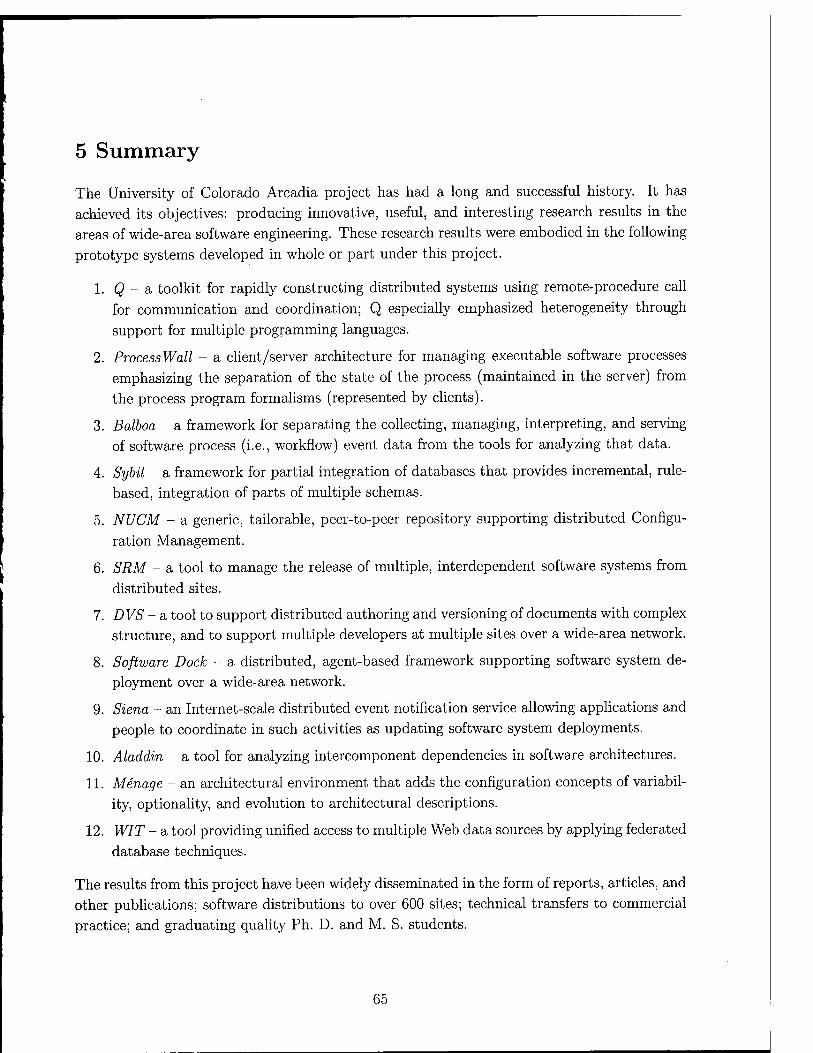
5 Summary
The University of Colorado Arcadia project has had a long and successful history. It has
achieved its objectives: producing innovative, useful, and interesting research results in the
areas of wide-area software engineering. These research results were embodied in the following
prototype systems developed in whole or part under this project.
1. Q - a toolkit for rapidly constructing distributed systems using remote-procedure call
for communication and coordination; Q especially emphasized heterogeneity through
support for multiple programming languages.
2. ProcessWall - a client/server architecture for managing executable software processes
emphasizing the separation of the state of the process (maintained in the server) from
the process program formalisms (represented by clients).
3. Balboa - a framework for separating the collecting, managing, interpreting, and serving
of software process (i.e., workflow) event data from the tools for analyzing that data.
4. Sybil - a framework for partial integration of databases that provides incremental, rule-
based, integration of parts of multiple Schemas.
5. NUCM - a generic, tailorable, peer-to-peer repository supporting distributed Configu-
ration Management.
6. SRM - a tool to manage the release of multiple, interdependent software systems from
distributed sites.
7. D VS - a tool to support distributed authoring and versioning of documents with complex structure, and to support multiple developers at multiple sites over a wide-area network.
8. Software Dock - a distributed, agent-based framework supporting software system de-
ployment over a wide-area network.
9. Siena - an Internet-scale distributed event notification service allowing applications and
people to coordinate in such activities as updating software system deployments.
10. Aladdin - a tool for analyzing intercomponent dependencies in software architectures.
11. Menage - an architectural environment that adds the configuration concepts of variabil-
ity, optionality, and evolution to architectural descriptions.
12. WIT - a tool providing unified access to multiple Web data sources by applying federated
database techniques.
The results from this project have been widely disseminated in the form of reports, articles, and
other publications; software distributions to over 600 sites; technical transfers to commercial
practice; and graduating quality Ph. D. and M. S. students.
65
6 References and Bibliography
Reverse Chronological List of Publications Funded by this Grant.
[1] J.A. Stafford and A.L. Wolf, "Software Architecture," Component-Based Software Engi-
neering: Putting the Pieces Together, G.T. Heineman and W.T. Councill, ed., Addison- Wesley, 2001.
[2] J.A. Stafford and A.L. Wolf, "Annotating Components to Support Component-Based
Static Analyses of Software Systems," Proceedings of Grace Hopper Conference 2000,
September 2000, Hyannis, MASS.
[3] P. Inverardi, A.L. Wolf, and D. Yankelevich, "Static Checking of System Behaviors
Using Derived Component Assumptions," ACM Transactions on Software Engineering and Methodology, 9(3):239-272 (July 2000).
[4] A. Carzaniga, D.S. Rosenblum, and A.L.Wolf, "Achieving Expressiveness and Scalability in an Internet-Scale Event Notification Service," Proc. of the 19th ACM Symposium on Principles of Distributed Computing, July 2000, Portland OR.
[5] Judith A. Stafford, "A Formal, Language-Independent, and Compositional Approach
to Control Dependence Analysis," Ph. D. Thesis, Aug. 2000, Department of Computer Science, University of Colorado, Boulder.
[6] A. Carzaniga, D. S. Rosenblum, and A. L. Wolf, "Content-Based Addressing and Rout-
ing: A General Model and its Application," Technical Report CU-CS-902-00, January 2000, Department of Computer Science, University of Colorado, Boulder.
[7] F. Parisi-Presicce and A.L. Wolf, "Foundations for Software Configuration Management
Policies using Graph Transformations," Proc. of the 2000 Conference on Fundamental
Approaches to Software Engineering, Lecture Notes in Computer Science 1783:304-318, Springer-Verlag, 2000.
[8] Richard A. Smith, "Analysis and Design for a Next Generation Software Release Man-
agement System," M. S. Thesis, Dec. 1999, Department of Computer Science, University of Colorado, Boulder.
[9] A. Carzaniga, D.S. Rosenblum, and A.L.Wolf, "Challenges for Distributed Event Ser-
vices: Scalability vs. Expressiveness," ICSE 99 Workshop on Engineering Distributed Objects (EDO'99), May 1999, Los Angeles CA.
[10] Andre van der Hoek, "A Reusable, Distributed Repository for Configuration Manage-
ment Policy Programming," Ph. D. Thesis, January 21, 2000, Department of Computer Science, University of Colorado, Boulder.
66

[11] C. Reid Turner, A. Fuggetta, L. Lavazza, and A.L. Wolf, "A Conceptual Basis for Feature
Engineering," Journal of Systems and Software, 49(1):3-15 (December 1999).
[12] A. van der Hoek, D. Heimbigner, and A.L. Wolf, "Capturing Architectural Configura-
bility: Variants, Options, and Evolution," Technical Report CU-CS-895-99, December
1999, Department of Computer Science, University of Colorado, Boulder.
[13] J.A. Stafford and A.L. Wolf, 'Annotating Components to Support Component-Based
Static Analyses of Software Systems," Technical Report CU-CS-896-99, December 1999,
Department of Computer Science, University of Colorado, Boulder.
[14] J.A. Stafford and A.L. Wolf, 'Architecture-Based Software Engineering," Technical Re-
port CU-CS-891-99, November 1999, Department of Computer Science, University of
Colorado, Boulder.
[15] A. Carzaniga, D. S. Rosenblum, and A. L. Wolf, "Interfaces and Algorithms for a Wide- Area Event Notification Service," Technical Report CU-CS-888-99, October, 1999, De-
partment of Computer Science, University of Colorado, Boulder.
[16] A. van der Hoek, "Configurable Software Architecture in Support of Configuration Man-
agement and Software Deployment," Proc. of the Doctoral Workshop of the 1999 Int'l.
Conf. on Software Engineering, pp. 732-733, May 1999, Los Angeles, CA.
[17] R. Hall, D. Heimbigner, and A. L. Wolf, "A Cooperative Approach to Support Software
Deployment Using the Software Dock," Proc. of ICSE'99: The 1999 Int'l Conf. on
Software Engineering, pp. 174-183, May 1999, Los Angeles, CA.
[18] P. Oreizy, M. M. Gorlick, R. N. Taylor, D. Heimbigner, G. Johnson, N. Medvidovic, A. Quilici, D. S. Rosenblum, and A. L. Wolf, "An Architecture-Based Approach to Self-
Adaptive Software," IEEE Intelligent Systems Special Issue on Self-Adaptive Software,
14(3):54-62 (May/June 1999).
[19] D. Heimbigner, R.S. Hall, and A.L. Wolf, "A Framework for Analyzing Configurations of
Deployable Software Systems," Proc. of the Fifth IEEE Int'l Conference on Engineering
of Complex Computer Systems, pp. 32-42, October 1999, Las Vegas, NV.
[20] Richard S. Hall, "Agent-based Software Configuration and Deployment," Ph. D. Thesis, April 1, 1999, Department of Computer Science, University of Colorado, Boulder.
[21] J.E. Cook and A.L. Wolf, "Software Process Validation: Quantitatively Measuring the Correspondence of a Process to a Model," ACM Transactions on Software Engineering
and Methodology 8(2):147-176 (April 1999).
67

[22] R.S. Hall, D. Heimbigner, and A.L. Wolf, "Specifying the Deployable Software Descrip-
tion Format in XML," Technical Report CU-SERL-207-99, March 1999, Software Engi-
neering Research Laboratory, Department of Computer Science, University of Colorado, Boulder.
[23] D. Compare, P. Inverardi, and A. L. Wolf, "Uncovering Architectural Mismatch in Com-
ponent Behavior," Science of Computer Programming, 33(2) (Feb. 1999).
[24] Carlton Reid Turner, "Feature Engineering of Software Systems," Ph. D. Thesis, Dec.
1998, Department of Computer Science, University of Colorado, Boulder.
[25] Antonio Carzaniga, "Architectures for an Event Notification Service Scalable to Wide-
area Networks," Dec. 1998, Ph. D. Thesis, Politecnico di Milano,
[26] A. Carzaniga, E. Di Nitto, D.S. Rosenblum, and A.L. Wolf, "Issues in Supporting
Event-Based Architectural Styles," 3rd International Software Architecture Workshop (ISAW3), November, 1998, Orlando, FL.
[27] J. A. Stafford and A. L. Wolf, "Architecture-Level Dependence Analysis in Support of
Software Maintenance," Proc. of the 3rd Int'l Software Architecture Workshop, Novem- ber 1998, Orlando, FL.
[28] A. van der Hoek, D. Heimbigner, and A. L. Wolf, "Versioned Software Architecture,"
Proc. of the 3rd Int'l Software Architecture Workshop, November 1998, Orlando, FLA.
[29] R. Hall, D. Heimbigner, and A. L. Wolf, "Evaluating Software Deployment Languages
and Schema: An Experience Report," Proc. of the 1998 Int'l Conf. on Software Mainte- nance, November 1998, Bethesda, MD,
[30] J.E. Cook and A.L. Wolf, "Event-Based Detection of Concurrency," Proc. of the 6th
Int'l Symposium on Foundations of Software Engineering, pp. 35-45, November 1998, Orlando, FLA.
[31] J. A. Stafford and A. L. Wolf, '"Dependence Analysis for Software Architectures," Proc. of the ASE'98 Doctoral Symposium, October 1998, Honolulu, HI.
[32] A. van der Hoek, D. Heimbigner, and A. L. Wolf, "Investigating the Applicability of Ar-
chitecture Description in Configuration Management and Software Deployment," Tech-
nical Report CU-CS-862-98, September 1998, Department of Computer Science, Uni- versity of Colorado, Boulder.
[33] A. van der Hoek, A. Carzaniga, D. Heimbigner, and A. L. Wolf, "A Generic, Reusable
Repository for Configuration Management Policy Programming," Technical Report CU-
CS-864-98, September 1998, Department of Computer Science, University of Colorado, Boulder.
68

[34] J.E. Cook, L.G. Votta, and A.L. Wolf, "Cost-Effective Analysis of In-Place Software
Processes," IEEE Transactions on Software Engineering 24(8):650-663 (August 1998).
[35] A. Carzaniga, D.S. Rosenblum, and A.L. Wolf, "Design of a Scalable Event Notification
Service: Interface and Architecture," Technical Report CU-CS-863-98, August 1998,
Department of Computer Science, University of Colorado, Boulder.
[36] R. Hall, D. Heimbigner, and A. L. Wolf, "Requirements for Software Deployment Lan-
guages," Proc. of the 8th Int'l Software Configuration Management Workshop, July
1998, Brussels, Belgium.
[37] A. van der Hoek, D. Heimbigner, and A. L. Wolf, "System Modeling Resurrected," Proc.
of the 8th Int'l Software Configuration Management Workshop, July 1998, Brussels,
Belgium.
[38] J.E. Cook and A.L. Wolf, "Discovering Models of Software Processes from Event-Based Data," ACM Transactions on Software Engineering and Methodology 7(3):215-249 (July
1998).
[39] J. A. Stafford, "Aladdin: A Tool for Analysis of Dependencies in Software Architec-
tures," Presentation for the Annual Symposium on Software Engineering and Technology
Transfer (ASSETT 1998), July 16, 1998, Motorola Museum, Schaumburg, IL.
[40] J.E. Cook and A.L. Wolf, "Balboa: A Framework for Event-Based Process Data Anal-
ysis," Proc. Fifth Int'l Conf. on the Software Process, pp. 99-110, June 1998, Lisle,
IL.
[41] J. A. Stafford, D. J. Richardson, and A. L. Wolf, "Architecture-level Dependence Anal- ysis for Software Systems," Proc. of the Int'l Workshop on the Role of Software Archi-
tecture in Testing and Analysis, June 1998, Marsala, Italy.
[42] J.A. Stafford, D.J. Richardson, and A.L. Wolf, "Aladdin: A Tool for Architecture-Level
Dependence Analysis of Software Systems," Technical Report CU-CS-858-98, April 1998,
Department of Computer Science, University of Colorado, Boulder.
[43] C. Reid Turner, A. Fuggetta, L. Lavazza, and A.L. Wolf, "Feature Engineering," Proc. of the 9th International Workshop on Software Specification and Design, pp. 162-164,
IEEE Computer Society, April 1998.
[44] A. Carzaniga, A. Fuggetta, R. S. Hall, A. van der Hoek, D. Heimbigner, and A. L. Wolf, "A Characterization Framework for Software Deployment Technologies," Technical Re-
port CU-CS-857-98, April 98, Department of Computer Science, University of Colorado,
Boulder.
69

[45] A. van der Hoek, R.S. Hall, A. Carzaniga, D. Heimbigner, and A.L. Wolf, "Software
Deployment: Extending Configuration Management Support into the Field," Crosstalk,
The Journal of Defense Software Engineering, 11(2) (February 1998).
[46] A. van der Hoek, D. Heimbigner, and A. L. Wolf, "Software Architecture, Configuration
Management, and Configurable Distributed Systems: A Menage a Trois," Technical
Report CU-CS-849-98, January, 1998, Department of Computer Science, University of Colorado, Boulder.
[47] J. C. Doppke, D. Heimbigner, and A. Wolf, "Software Process Modeling and Execution
Within Virtual Environments," ACM Transactions on Software Engineering, 7(1).-1-40 (January 1998).
[48] R. S. Hall, D. Heimbigner, and A. L. Wolf, "Software Deployment and Languages and
Schema," Technical Report CU-SERL-203-97, 18 December 1997, Software Engineering
Research Laboratory Department of Computer Science, University of Colorado, Boulder.
[49] J.A. Stafford, D.J. Richardson, and A.L. Wolf, "Chaining: A Software Architecture
Dependence Analysis Technique," Technical Report CU-CS-845-97, September 1997, Department of Computer Science, University of Colorado, Boulder.
[50] P. Inverardi, A.L. Wolf, and D. Yankelevich, "Checking Assumptions in Component
Dynamics at the Architectural Level," Proc. of the Second International Conference on Coordination Models and Languages, September 1997, Berlin, Germany.
[51] D. Heimbigner and A. L. Wolf, "Micro-Processes," International Workshop on Research
Directions in Process Technology, 7-9 July 1997, Nancy, France.
[52] A. van der Hoek, R. S. Hall, D. Heimbigner, and A. L. Wolf, "Software Release Manage-
ment," Sixth European Software Engineering Conference, Lecture Notes in Computer Science 1301:159-175, Springer-Verlag, Berlin, 1997.
[53] R. S. Hall, D. Heimbigner, A. van der Hoek, and A. L. Wolf, "An Architecture for Post-
Development Configuration Management in a Wide-Area Network," Proc. of the 17th
International Conference on Distributed Computing Systems, pp. 269-278, May 1997, Baltimore, MD.
[54] D. S. Rosenblum and A. L. Wolf, "A Design Framework for Internet-Scale Event Ob-
servation and Notification," Sixth European Software Engineering Conference, Lecture
Notes in Computer Science 1301:344-360, Springer-Verlag, Berlin, 1997.
[55] C. Reid Turner, A. Fuggetta, and A. L. Wolf, "Toward Feature Engineering of Software
Systems," Technical Report CU-CS-830-97, February 1997, Department of Computer Science, University of Colorado, Boulder.
70

[56] R. S. Hall, D. Heimbigner, A. van der Hoek, and A. L. Wolf, "The Software Dock: A
Distributed, Agent-based Software Deployment System," Technical Report CU-CS-832-
97, February 1997, Department of Computer Science, University of Colorado, Boulder.
[57] J. E. Cook, L. G. Votta, and A. L. Wolf, "A Methodology for Cost-Effective Anal-
ysis of In-Place Software Processes," Technical Report CU-CS-825-97, January 1997,
Department of Computer Science, University of Colorado, Boulder.
[58] Jonathan E. Cook, "Process Discovery and Validation Through Event Data Analysis,"
Ph. D. Thesis, Dec. 1996, Department of Computer Science, University of Colorado,
Boulder.
[59] D.M. Heimbigner and A.L. Wolf, "Post-Deployment Configuration Management," Proc.
of the Sixth International Workshop on Software Configuration Management, Lecture
Notes in Computer Science 1167:272-276, Springer-Verlag, 1996.
[60] J. E. Cook and A. L. Wolf, "Discovering Models of Software Processes from Event-Based
Data," Technical Report CU-CS-819-96, November 1996, Department of Computer Sci-
ence, University of Colorado, Boulder.
[61] D. J. Richardson and A. L. Wolf, "Software Testing at the Architectural Level," Second International Software Architecture Workshop (ISAW-2), pp. 68-71, October 1996, San
Francisco, CA.
[62] John C. Doppke, "Software Process Modeling and Execution within Virtual Environ-
ments," M. S. Thesis, Aug. 1996, Department of Computer Science, University of Col-
orado, Boulder.
[63] R. King and M. Novak, "Sybil: A System for the Incremental Evolution of Distributed,
Heterogeneous Database Layers," Second Annual Americas Conference on Information
Systems: Minitrack on Heterogeneous Interoperability, August 1996, Phoenix, AZ.
[64] R. King and M. Novak, "Supporting Information Infrastructure for Distributed, Het-
erogeneous Knowledge Discovery," Workshop on Research Issues on Data Mining and
Knowledge Discovery, June 1996, Montreal, Canada.
[65] A. van der Hoek, D. Heimbigner, and A. Wolf, "Software Release Management,"
WWW/OMG Workshop on Distributed Objects and Mobile Code, 23-26 June 1996,
Boston, MA.
[66] J. Doppke, D. Heimbigner, and A. Wolf, "Language-based Support for Metadata," First
IEEE Metadata Conference, 15-19 April 1996, Silver Springs, MD.
[67] D. Heimbigner and A. Wolf, "Software in the Field Needs Process Too," Tenth Interna-
tional Software Process Workshop, 23-26 June 1996, Ventron, France.
71
[68] R.M. Gonzales and A.L. Wolf, "A Facilitator Method for Upstream Design Activities
with Diverse Stakeholders," Proc. of the 1996 International Conference on Requirements Engineering, pp. 190 197, IEEE Computer Society, April 1996.
[69] D. Heimbigner, A. L. Wolf, and A. van der Hoek, "A Generic, Peer-to-Peer Repository
for Distributed Configuration Management," Proc. of the 18th Intl. Conf. on Software Engineering, March 1996, Berlin, Germany.
[70] M. Maybee, D. Heimbigner, and L. J. Osterweil, "Multilanguage Interoperability in
Distributed Systems," Proc. of the 18th Intl. Conf. on Software Engineering, March 1996, Berlin, Germany.
[71] P.T. Devanbu, D.S. Rosenblum, and A.L. Wolf, "Generating Testing and Analysis Tools
with Aria," ACM Trans, on Software Engineering and Methodology, 5(l):42-62 (Jan. 1996).
[72] G. Zhou, R. Hull, R. King and J-C. Franchitti, "Supporting Data Integration and Ware-
housing Using H20," Special issue of the IEEE Data Engineering Bulletin: Materialized Views and Data Warehousing, J. Widom (ed.), August 1995.
[73] Arcadia Consortium, "The Collected Arcadia Papers: Volume I: Software Engineering Environment Infrastructure," 1995.
[74] Arcadia Consortium, "The Collected Arcadia Papers: Volume II: Analysis and Testing," 1995.
[75] G. Zhou, R. Hull and R. King, "Generating Data Integration Mediators that Use Mate- rialization," Journal of Intelligent Information Systems.
[76] J.E. Cook and A.L. Wolf, "Automating Process Discovery through Event-Data Anal-
ysis," Proc. Seventeenth International Conference on Software Engineering, pp. 73-82, April 1995, Seattle, WA.
[77] P. Inverardi and A. Wolf, "Formal Specification and Analysis of Software Architectures
Using the Chemical Abstract Machine Model," IEEE Trans, on Software Engineering, 21(4): 373-386 (April 1995).
[78] A. van der Hoek, D. Heimbigner, and A. Wolf, "Does Configuration Management Re-
search Have a Future?," Fifth Software Configuration Management Workshop, 25 April 25 1995, Seattle, WA.
[79] D. Heimbigner, "The Tps Reference Manual," Technical Report CU-Arcadia-104, Arca- dia Consortium, revised 24 March 1995.
72

[80] S. M. Sutton, Jr., D. Heimbigner, and L. J. Osterweil, "APPL/A: A Language for Software-Process Programming," ACM Trans, on Software Engineering 4(3):221-286
(July 1995).
[81] Mark Maybee, "Component-Object Interoperability in a Heterogeneous Distributed En- vironment," Ph. D. Thesis, Dec. 1994, Department of Computer Science, University of
Colorado, Boulder.
[82] J. E. Cook and A.L.Wolf, "Toward Metrics for Process Validation," Proc. Third Inter- national Conference on the Software Process, pp. 33-44, October 1994, Reston, VA.
[83] S. M. Sutton, Jr. and P. L. Tarr, "Language Interoperability Issues in the Integration of Heterogeneous Systems," Technical Report CU-CS-675-93, September 1994, Department of Computer Science, University of Colorado, Boulder.
[84] J.C. Franchitti, R. King, and O. Boucelma, "A Toolkit to Support Scalable Persistent Object Base Infrastructures," Proc. of'the Sixth International Workshop on Persistent Object Systems, 5-9 September 1994, Tarascon, France.
[85] O. Boucelma, J. Dalrymple, M. Doherty, J. C. Franchitti, R. Hull, R. King, and G. Zhou, "Incorporating Active and Multi-database-state Services into an OSA-Compliant Interoperability Toolkit." Journees Bases de Donnees Avancees, 29 Aug. 1994, Nancy,
France.
[86] S. M. Sutton, Jr., "Databases in Software Environments: Are They Passe?," Research Is- sues in the Intersection Between Software Engineering and Databases—Workshop Proc,
May 1994, Sorrento, Italy.
73

7 Symbols, Abbreviations, and Acronyms
Aladdin An architecture analysis tool
BADD Battlefield Awareness and Data Dissemination
Balboa A software process data management system
CM Configuration Management
CORBA Common Object Request Broker Architecture (from OMG)
CPOF Command Post of the Future
DARPA Defense Advanced Research Projects Agency
DASADA Dynamic Assembly for System Adaptability, Dependability, and Assurance
DSD Deployable Software Description
DVS Distributed Versioning System
EDCS Evolutionary Design of Complex Software
GIG Global Information Grid
JBI Joint Battlespace Infosphere
Menage Configurable Architecture System
NUCM Network Unified Configuration Management
OMG Object Management Group
PDCM Post-Development Configuration Management
Q CORBA 2 Middleware System
RCS Revision Control System
SERL Software Engineering Research Laboratory (at the University of Colorado)
Siena Scalable Internet Event Notification Architectures
SRM Software Release Manager
Sybil Database Integration Tool
WebDAV Web-based Distributed Authoring and Versioning
WIT Web Integration Tool
XML Extensible Markup Language
«U.S. GOVERNMENT PRINTING OFFICE: 2001-610-055-10079
74

DISTRIBUTION LIST
addresses number of copies
R03ER J. DZIEGIEL* AF9L/IFTD 525 BROOKS ROAD ROME/ NY 13441-4505
JR,
UMIVERSIT* OF COLORADO COMPUTER SCIENCE DEPARTMENT BOULDER, CO 30309-3430
AFRL/IFOIL TECHNICAL LIBRARY 26 ELECTRONIC ?KY ROHE NY 13441-4514
ATTENTION: DTIC-OCC DEFENSE TECHNICAL INFO CENTER 3725 JOHN J. KING.M*N R3AD, STE FT. 8ELV0IR, VA 22060-6218
0944
DEFENSE ADVANCED RESEARCH PROJECTS AGENCY 3701 NORTH FAIRFAX DRIVE ARLINGTON VA 22203-1714
ATTN: NAN PFRIWHER IIT RESEARCH INSTITUTE 231 HILL ST. ROME, NY 13440
AFIT ACADEMIC LIBRARY AFIT/LDR, 2950 P.STREET AREA 3, 3LD3 642 WRIGHT-PATTERSON AF8 ON 45433-7765
AFRL/HESC-TDC 2693 S STREET* SLDS 190 WRIGHT-PATTERSON AF8 OH 45433-7604
DL-1
ATTN: SMDC IM PL 1 US ARMY SPACE ä MISSILE DSF CMD P.O. 30X 1500 HUNTSVILLE AL 35307-3301
COMMANDER, CODE 4TL000D 1 TECHNICAL LIBRARY, NAWC-WD 1 ADMINISTRATION CIRCLE CHINA LAKE CA 93555-6100
CDR, US ARMY AVIATION % MISSILE CMD 2 REDSTONE SCIENTIFIC INFORMATION CTR ATTN: AMSAM-RD-08-R, (DOCUMENTS) REDSTONE ARSENAL AL 35S98-500Ö
REPORT LI3RARY 1 MS P364 LOS ALAMOS NATIONAL LABORATORY LOS ALAMOS NM 87545
ATTN: D* 30RAH HART 1 AVIATION 3RANCH SVC 122.10 F0B10A, RM 931 80D INDEPENDENCE AVE, SW ]
WASHINGTON OC 20591 1
AFIWC/MSY 102 HALL 3LVD, STE 315 SAN ANTONIO TX 78243-7016
ATTN: KAROLA M. YOURISON SOFTWARE ENGINEERING INSTITUTE 4500 FIFTH AVENUE PITTSBURGH PA 15213
USAF/AIR FORCE RESEARCH LABORATORY AFRL/VS0SA<LIBRARY-3LDS 1103) 5 BRIGHT DRIVE HANSCOM AF3 MA 01731-3004
ATTN: EILEEN LADUKE/0460 MITRE CORPORATION 202 BURLINGTON RÖ BEDFORD MA 01730
DL-2
OUSD<P)/DTSA/DUTO ATTN: PATRICK G- SüLLTVAN/- 400 ARW NAVY DRIVE SUITE 300 ARLINGTON VA 22202
JR.
AFRL/IFT 525 BROOKS ROAD ROME/- NY 15441-4505
AFRL/IFTM 525 BROOKS ROAD ROME, NY 15441-4505
DL-3

MISSION OF
AFRL/INFORMÄTIONDIRECTORATE (IF)
The advancement and application of Information Systems Science
and Technology to meet Air Force unique requirements for
Information Dominance and its transition to aerospace systems to
meet Air Force needs.
J