Embed Size (px)
Citation preview
2234 Wenneca Ave., Fort Worth, TX 76102 USA Phone: 817-870-8888 Fax: 817-870-9199 E-mail: [email protected]
Greenslade & Company, Inc. Web site: www.greensladeandcompany.com
TAPPING SCREW PERFORMANCE SPECIFICATIONS F.I.P. - 1000.1 THROUGH F.I.P. - 1000.7
Copyright 2003 © by Greenslade and Company. Printed in the United States of America. All rights reserved. This booklet, or parts thereof, may not be reproduced in any form without permission of
Greenslade and Company.
2234 Wenneca Ave., Fort Worth, TX 76102 USA Phone: 817-870-8888 Fax: 817-870-9199 E-mail: [email protected]
Greenslade & Company, Inc. Web site: www.greensladeandcompany.com
Third Edition August 2003
TAPPING SCREW PERFORMANCE SPECIFICATIONS
F.I.P. - 1000.1 THROUGH F.I.P. - 1000.7
TAPPING SCREWS: Case Hardened Carbon Steel; Inch and Metric
Types: • A • AB, B, BT(25) • F,T(23) • Thread Rolling Screws • Self Drilling Screws
The purpose of this specification is to provide fastener users, distributors, importers and manufacturers with a series of simple to understand and perform tests which will help to detect fastener problems before they cause productivity losses and/or product damage. Unlike other standards, F.I.P. has made an effort to explain within each test description the purpose of the test, indicating what production problems may arise from a particular screw failure. It further explains and illustrates all apparatus required to perform the test, the step-by-step procedure, the description of a failure and the possible causes of that failure. Every effort has been made to present this valuable information in an easy to understand way so that inexperienced personnel can successfully perform these tests by simply using the suggested equipment and following the procedures step by step. Potential fastener failure problems should be caught prior to actual use in assembly. Hopefully this document will aid American industry in accomplishing just that, thus improving overall production efficiency which is crucial to the future of our economy. The Tapping Screw performance tests in the following pages are described in the sequence in which they should be performed when testing each, lot. The charts covering each type of tapping screw also list the test requirements in this same preferred order, left to right. Also in the back of this standard are two (2) recommended test forms which list the tests in order to help fastener inspectors to conduct the tests on each lot of parts systematically and efficiently. The first test form is to be used for all types of tapping screws. The second is an additional sheet which should be used for the Drill-Drive Test for Self-Drilling Screws. These forms should be filled out and kept for future reference as a record of performance on each lot. Since the charts and forms are created in the recommended order for testing, if the parts fail any one test they may be rejected at that point without conducting further tests. This document is based on an analysis and comparison of the tapping screw specifications published by General Motors Corporation and Ford Motor Company. These were selected because they are the most com-prehensive on this subject and, in general, the most practical. This is probably because between these two firms they use more tapping screws each year than any other firms in the world. Complete copies of their standards are available for a fee upon request.
2234 Wenneca Ave., Fort Worth, TX 76102 USA Phone: 817-870-8888 Fax: 817-870-9199 E-mail: [email protected]
Greenslade & Company, Inc. Web site: www.greensladeandcompany.com
This standard only covers the performance of tapping screws. For dimensional guidelines we recommend the A.N.S.I. B18.6.4, 1981. Ordering information for this document is available upon request. The sample size recommendations are based on the proposal of A.N.S.I. 818.18.1 M dated 1982 for general purpose fasteners. Ordering information for this complete document is available upon request. References; The following standards were used in the compilation of this standard: Ford Motor Product Engineering Standards General Motors Engineering Standards
ESS-M1A160-A August 1973ES-20002-S100 August 1973
ES-20003-S1000 December 1970ES-20002-S100 August 1973
GM6010M December 1984 GM6170M April 1970
GM6171 M April 1985 GM6172M April 1986 The content of this standard is advisory only and its use by anyone is entirely voluntary. Reliance on its content for any purpose by anyone is at the sole risk of that person and F.I.P. is not responsible for any loss, claim or damage arising therefrom. These tests are intended as referee tests for acceptance but the user must determine if a given fastener is suitable and acceptable in his own application regardless of these test results. In compiling this standard, F.I.P. has made a determined effort to present its contents accurately. If errors exist they are typographical and F.I.P. is not responsible for any claim traceable to such error. F.I.P. has not investigated, nor will it investigate, patents which may apply to the subject contents. Prospective users of this standard are responsible for advising themselves and protecting themselves against any patent infringement liability which may arise out of such use.
2234 Wenneca Ave., Fort Worth, TX 76102 USA Phone: 817-870-8888 Fax: 817-870-9199 E-mail: [email protected]
Greenslade & Company, Inc. Web site: www.greensladeandcompany.com
F.I.P. 1000
TAPPING SCREW PERFORMANCE SPECIFICATIONS
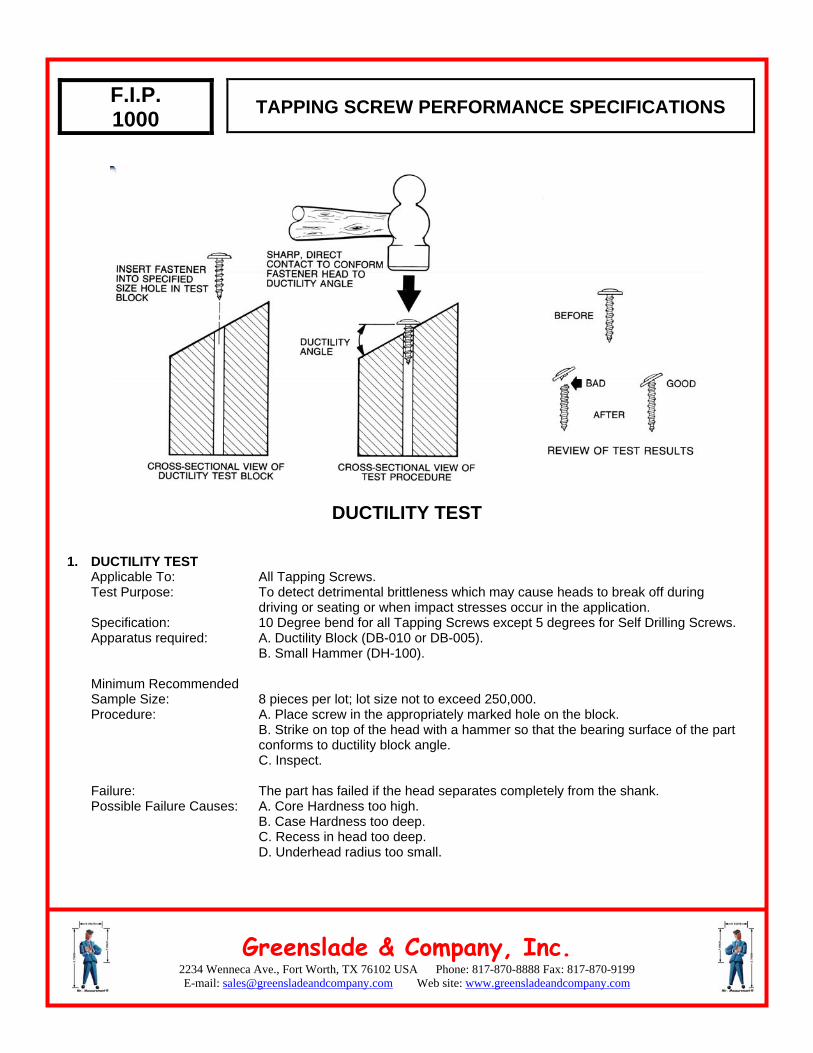
DUCTILITY TEST
1. DUCTILITY TEST Applicable To: Test Purpose:
Specification: Apparatus required: Minimum Recommended Sample Size: Procedure: Failure: Possible Failure Causes:
All Tapping Screws. To detect detrimental brittleness which may cause heads to break off during driving or seating or when impact stresses occur in the application. 10 Degree bend for all Tapping Screws except 5 degrees for Self Drilling Screws. A. Ductility Block (DB-010 or DB-005). B. Small Hammer (DH-100). 8 pieces per lot; lot size not to exceed 250,000. A. Place screw in the appropriately marked hole on the block. B. Strike on top of the head with a hammer so that the bearing surface of the part conforms to ductility block angle. C. Inspect. The part has failed if the head separates completely from the shank. A. Core Hardness too high. B. Case Hardness too deep. C. Recess in head too deep. D. Underhead radius too small.
2234 Wenneca Ave., Fort Worth, TX 76102 USA Phone: 817-870-8888 Fax: 817-870-9199 E-mail: [email protected]
Greenslade & Company, Inc. Web site: www.greensladeandcompany.com
F.I.P. 1000 TAPPING SCREW PERFORMANCE SPECIFICATIONS
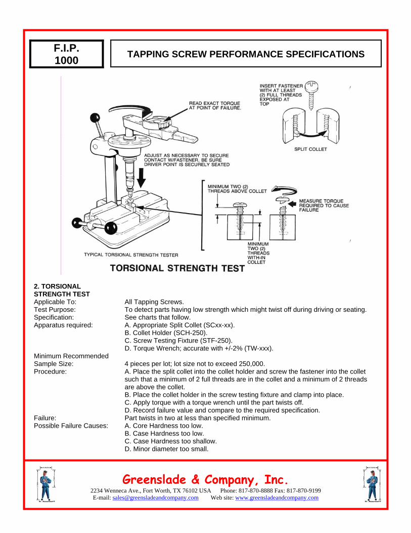
2. TORSIONAL STRENGTH TEST Applicable To: Test Purpose: Specification: Apparatus required: Minimum Recommended Sample Size: Procedure: Failure: Possible Failure Causes:
All Tapping Screws. To detect parts having low strength which might twist off during driving or seating. See charts that follow. A. Appropriate Split Collet (SCxx-xx). B. Collet Holder (SCH-250). C. Screw Testing Fixture (STF-250). D. Torque Wrench; accurate with +/-2% (TW-xxx). 4 pieces per lot; lot size not to exceed 250,000. A. Place the split collet into the collet holder and screw the fastener into the collet such that a minimum of 2 full threads are in the collet and a minimum of 2 threads are above the collet. B. Place the collet holder in the screw testing fixture and clamp into place. C. Apply torque with a torque wrench until the part twists off. D. Record failure value and compare to the required specification. Part twists in two at less than specified minimum. A. Core Hardness too low. B. Case Hardness too low. C. Case Hardness too shallow. D. Minor diameter too small.
2234 Wenneca Ave., Fort Worth, TX 76102 USA Phone: 817-870-8888 Fax: 817-870-9199 E-mail: [email protected]
Greenslade & Company, Inc. Web site: www.greensladeandcompany.com
F.I.P. 1000
TAPPING SCREW PERFORMANCE SPECIFICATIONS
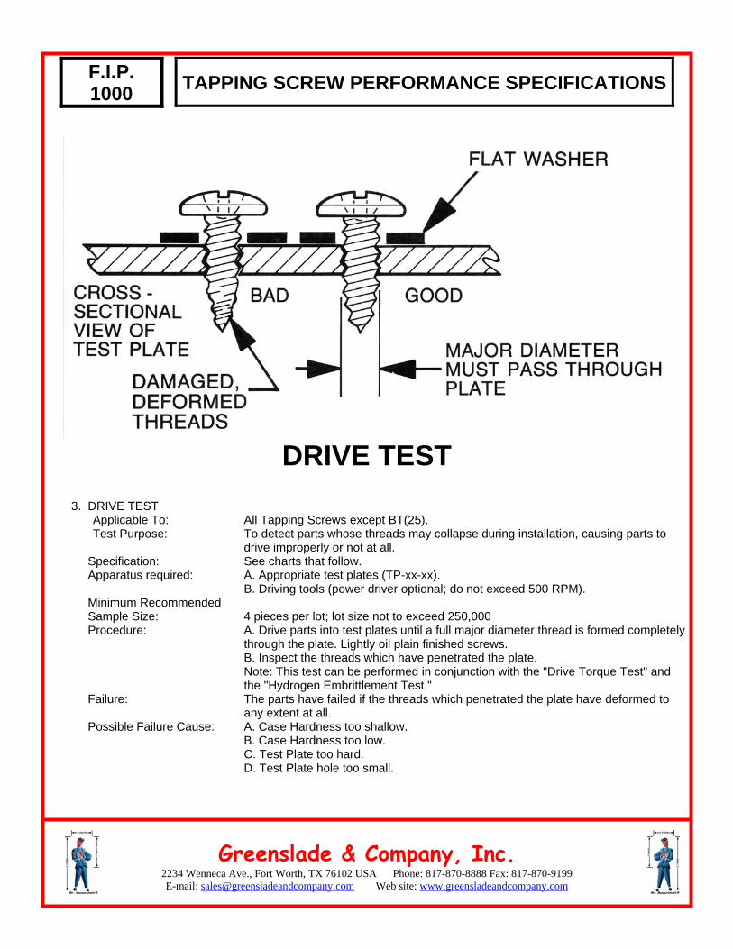
DRIVE TEST
3. DRIVE TEST
Applicable To: Test Purpose:
Specification: Apparatus required: Minimum Recommended Sample Size: Procedure: Failure: Possible Failure Cause:
All Tapping Screws except BT(25). To detect parts whose threads may collapse during installation, causing parts to drive improperly or not at all. See charts that follow. A. Appropriate test plates (TP-xx-xx). B. Driving tools (power driver optional; do not exceed 500 RPM). 4 pieces per lot; lot size not to exceed 250,000 A. Drive parts into test plates until a full major diameter thread is formed completely through the plate. Lightly oil plain finished screws. B. Inspect the threads which have penetrated the plate. Note: This test can be performed in conjunction with the "Drive Torque Test" and the "Hydrogen Embrittlement Test." The parts have failed if the threads which penetrated the plate have deformed to any extent at all. A. Case Hardness too shallow. B. Case Hardness too low. C. Test Plate too hard. D. Test Plate hole too small.
2234 Wenneca Ave., Fort Worth, TX 76102 USA Phone: 817-870-8888 Fax: 817-870-9199 E-mail: [email protected]
Greenslade & Company, Inc. Web site: www.greensladeandcompany.com
F.I.P. 1000
TAPPING SCREW PERFORMANCE SPECIFICATIONS
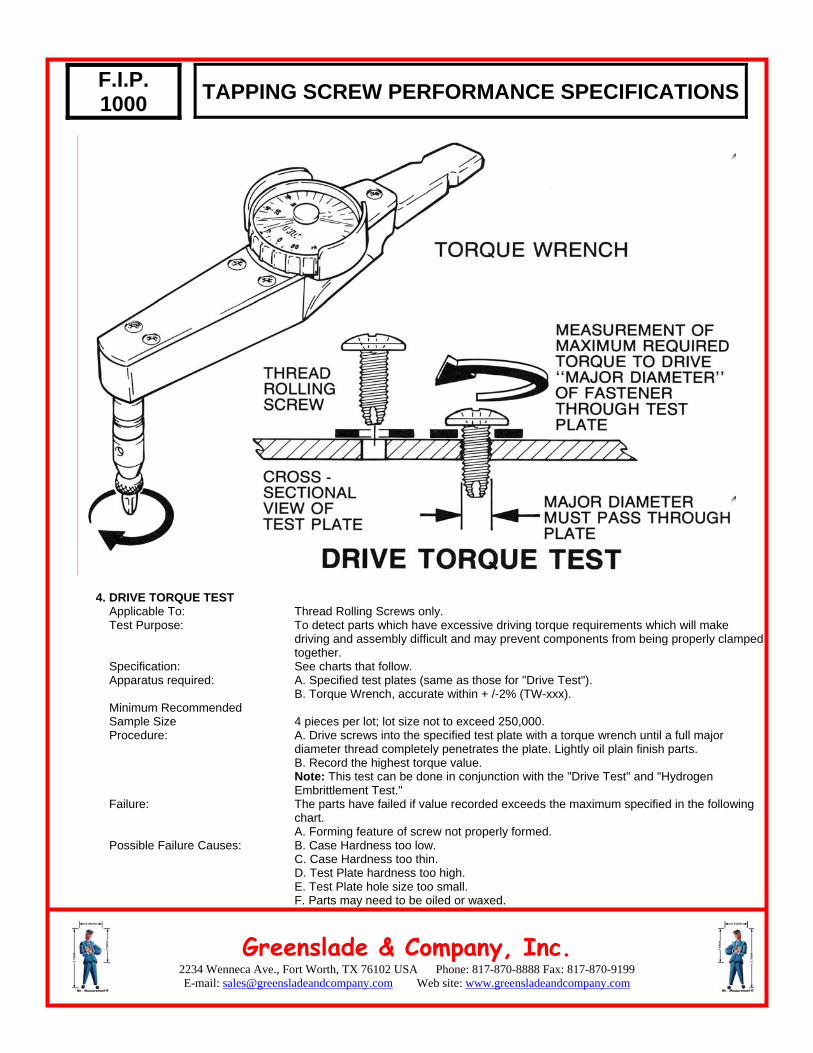
4. DRIVE TORQUE TEST Applicable To: Test Purpose: Specification: Apparatus required: Minimum Recommended Sample Size Procedure: Failure: Possible Failure Causes:
Thread Rolling Screws only. To detect parts which have excessive driving torque requirements which will make driving and assembly difficult and may prevent components from being properly clamped together. See charts that follow. A. Specified test plates (same as those for "Drive Test"). B. Torque Wrench, accurate within + /-2% (TW-xxx). 4 pieces per lot; lot size not to exceed 250,000. A. Drive screws into the specified test plate with a torque wrench until a full major diameter thread completely penetrates the plate. Lightly oil plain finish parts. B. Record the highest torque value. Note: This test can be done in conjunction with the "Drive Test" and "Hydrogen Embrittlement Test." The parts have failed if value recorded exceeds the maximum specified in the following chart. A. Forming feature of screw not properly formed. B. Case Hardness too low. C. Case Hardness too thin. D. Test Plate hardness too high. E. Test Plate hole size too small. F. Parts may need to be oiled or waxed.
2234 Wenneca Ave., Fort Worth, TX 76102 USA Phone: 817-870-8888 Fax: 817-870-9199 E-mail: [email protected]
Greenslade & Company, Inc. Web site: www.greensladeandcompany.com
F.I.P. 1000
TAPPING SCREW PERFORMANCE SPECIFICATIONS
DRILL DRIVE TEST
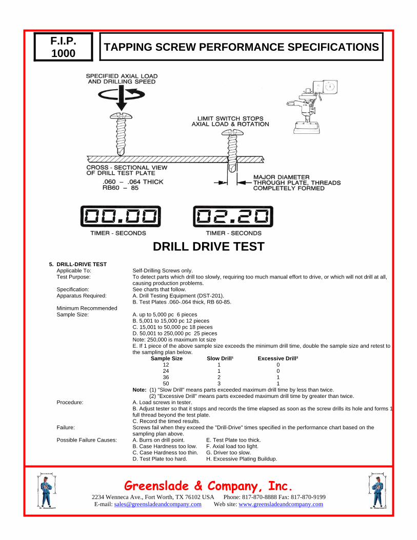
5. DRILL-DRIVE TEST Applicable To: Test Purpose: Specification: Apparatus Required: Minimum Recommended Sample Size: Procedure: Failure: Possible Failure Causes:
Self-Drilling Screws only. To detect parts which drill too slowly, requiring too much manual effort to drive, or which will not drill at all, causing production problems. See charts that follow. A. Drill Testing Equipment (DST-201). B. Test Plates .060-.064 thick, RB 60-85. A. up to 5,000 pc 6 pieces B. 5,001 to 15,000 pc 12 pieces C. 15,001 to 50,000 pc 18 pieces D. 50,001 to 250,000 pc 25 pieces Note: 250,000 is maximum lot size E. If 1 piece of the above sample size exceeds the minimum drill time, double the sample size and retest to the sampling plan below. Sample Size Slow Drill¹ Excessive Drill² 12 1 0 24 1 0 36 2 1 50 3 1 Note: (1) "Slow Drill" means parts exceeded maximum drill time by less than twice. (2) "Excessive Drill" means parts exceeded maximum drill time by greater than twice. A. Load screws in tester. B. Adjust tester so that it stops and records the time elapsed as soon as the screw drills its hole and forms 1 full thread beyond the test plate. C. Record the timed results. Screws fail when they exceed the "Drill-Drive" times specified in the performance chart based on the sampling plan above. A. Burrs on drill point. E. Test Plate too thick. B. Case Hardness too low. F. Axial load too light. C. Case Hardness too thin. G. Driver too slow. D. Test Plate too hard. H. Excessive Plating Buildup.
2234 Wenneca Ave., Fort Worth, TX 76102 USA Phone: 817-870-8888 Fax: 817-870-9199 E-mail: [email protected]
Greenslade & Company, Inc. Web site: www.greensladeandcompany.com
F.I.P. 1000
TAPPING SCREW PERFORMANCE SPECIFICATIONS
HYDROGEN EMBRITTLEMENT TEST
6. HYDROGEN EMBRITTLEMENT TEST Applicable to: Test Purpose: Warning: Specifications: Apparatus required: Minimum Recommended Sample Size: Procedure: Failure: Possible Failure Causes:
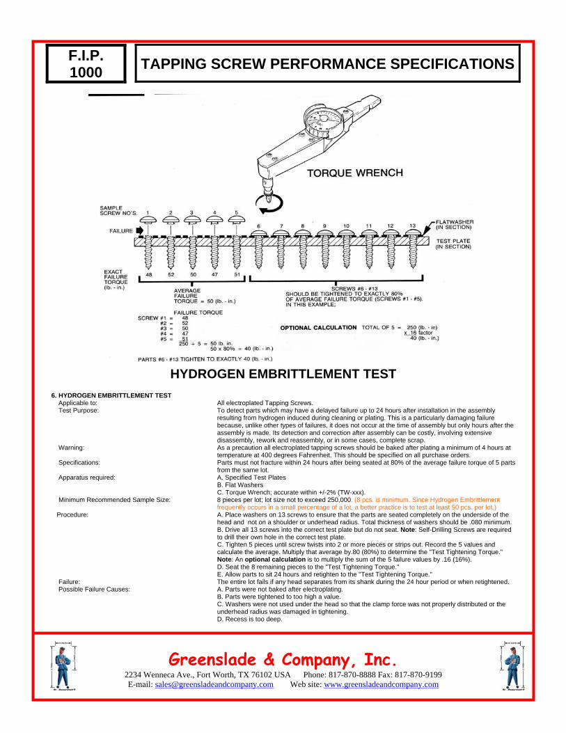
All electroplated Tapping Screws. To detect parts which may have a delayed failure up to 24 hours after installation in the assembly resulting from hydrogen induced during cleaning or plating. This is a particularly damaging failure because, unlike other types of failures, it does not occur at the time of assembly but only hours after the assembly is made. Its detection and correction after assembly can be costly, involving extensive disassembly, rework and reassembly, or in some cases, complete scrap. As a precaution all electroplated tapping screws should be baked after plating a minimum of 4 hours at temperature at 400 degrees Fahrenheit. This should be specified on all purchase orders. Parts must not fracture within 24 hours after being seated at 80% of the average failure torque of 5 parts from the same lot. A. Specified Test Plates B. Flat Washers C. Torque Wrench; accurate within +/-2% (TW-xxx). 8 pieces per lot; lot size not to exceed 250,000. (8 pcs. is minimum. Since Hydrogen Embrittlement frequently occurs in a small percentage of a lot, a better practice is to test at least 50 pcs. per lot.) A. Place washers on 13 screws to ensure that the parts are seated completely on the underside of the head and not on a shoulder or underhead radius. Total thickness of washers should be .080 minimum. B. Drive all 13 screws into the correct test plate but do not seat. Note: Self-Drilling Screws are required to drill their own hole in the correct test plate. C. Tighten 5 pieces until screw twists into 2 or more pieces or strips out. Record the 5 values and calculate the average. Multiply that average by.80 (80%) to determine the "Test Tightening Torque." Note: An optional calculation is to multiply the sum of the 5 failure values by .16 (16%). D. Seat the 8 remaining pieces to the "Test Tightening Torque." E. Allow parts to sit 24 hours and retighten to the "Test Tightening Torque." The entire lot fails if any head separates from its shank during the 24 hour period or when retightened. A. Parts were not baked after electroplating. B. Parts were tightened to too high a value. C. Washers were not used under the head so that the clamp force was not properly distributed or the underhead radius was damaged in tightening. D. Recess is too deep.
2234 Wenneca Ave., Fort Worth, TX 76102 USA Phone: 817-870-8888 Fax: 817-870-9199 E-mail: [email protected]
Greenslade & Company, Inc. Web site: www.greensladeandcompany.com
F.I.P. 1000
TAPPING SCREW PERFORMANCE SPECIFICATIONS
7. COMBINATION TEST RECOMMENDATIONS Purpose of Recommendation: Tests: Procedure (per lot): 8. HARDNESS TESTING Applicable To: Test Purpose: Apparatus: Specification: Core Hardness: Case Hardness: Case Depth: Minimum Recommended Sample Size:
The following 3 or at least 2 of the 3 tests should be done on all tapping screws to determine their acceptability. This combined test will help you to do all 3 in the least amount of time. Drive Test. Drive Torque Test (Thread Rolling Screws only). Hydrogen Embrittlement Test. A. Place flat washers on 13 screws to insure tension underhead upon seating. B. Drive all screws into the specified test plate so that the major diameter of the screw thread pro trudes completely through the plate but do not seat the parts. C. If testing Thread Rolling Screws, record the maximum driving torque and compare to the specifica tion to determine acceptability (Drive Torque Test, Test #4.) D. Examine all of the screw threads protruding through the plate. If any of the threads are deformed the lot is rejectable (Drive Test, Test #3). E. Tighten 5 of the 13 parts to failure (screws broken into 2 or more pieces). Record the failure values and calculate the sum. Multiply the sum by .16 (16%) to determine the "Test Tightening Torque." Tighten the next 8 or more screws (8 pcs. is minimum. Since Hydrogen Embrittlement frequently occurs in a small percentage of a lot, a better practice is to test at least 50 pcs. per lot) to that value and allow to sit for 24 hours. Retighten the parts to the "Test Tightening Torque" after 24 hours. If any parts break before or while retightening the lot is rejectable. All Tapping Screws. To analyze parts which have failed one or more of the previously described performance tests. A. Core hardness 1. Belt sander (S-100). 2. Standard Hardness Tester (HTR-100). B. Case Hardness: Micro-Hardness Tester (MHP-500). All except Self- Self-Drilling Screws Drilling Screws RC 28-38 RC 32-39 RC 45 min. RC 52-58 #2 through #6 .002-.007 same #7 through #12 .004-.009 same 1/4 and larger .006-.011 same 8 pc. per lot; lot size not to exceed 250,000.
Note: Material shall be from cold heading quality, killed steel wire having 0.13%-0.27% carbon and 0.64-1.71% manganese.
2234 Wenneca Ave., Fort Worth, TX 76102 USA Phone: 817-870-8888 Fax: 817-870-9199 E-mail: [email protected]
Greenslade & Company, Inc. Web site: www.greensladeandcompany.com
F.I.P. 1000
TAPPING SCREW PERFORMANCE SPECIFICATIONS
9. RECESS AND SLOT MEASUREMENT Applicable To: Test Purpose: Apparatus Required: Sample Size: Procedure: Failure: Possible Failure Causes:
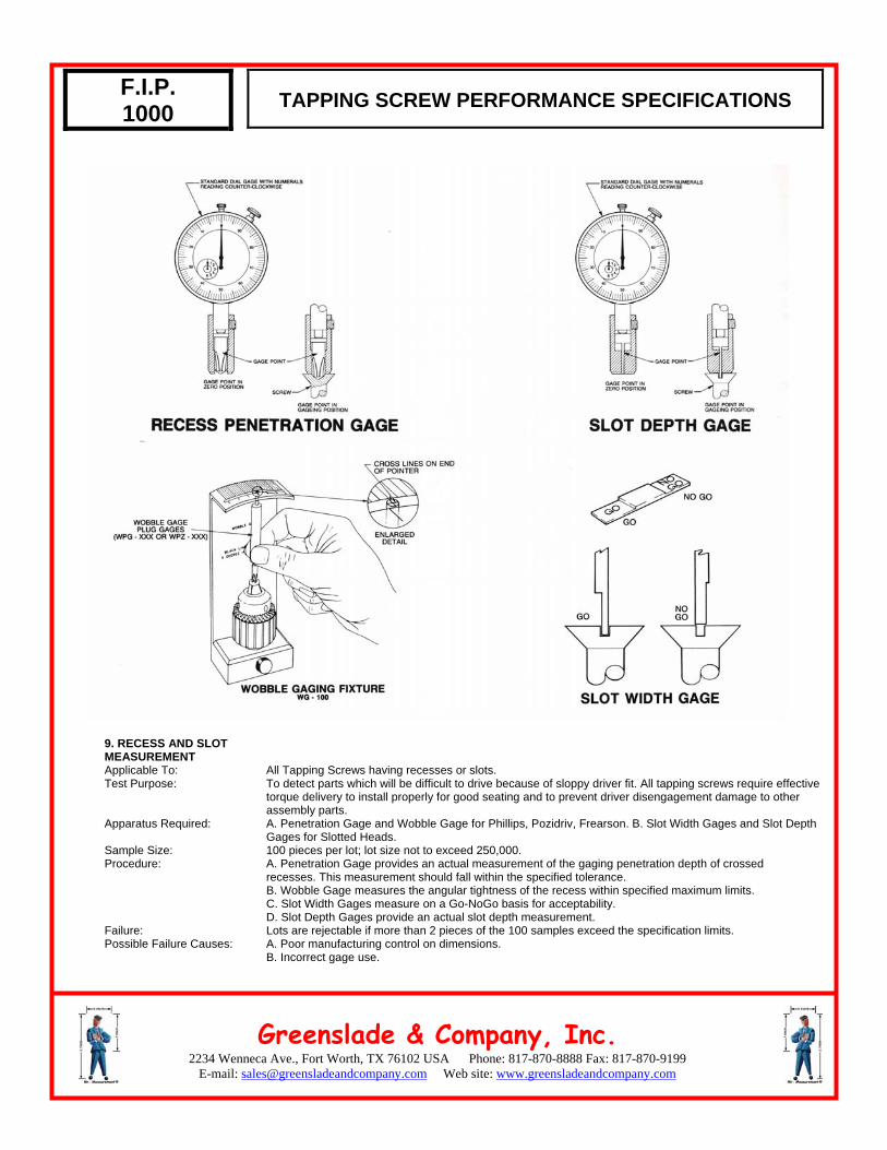
All Tapping Screws having recesses or slots. To detect parts which will be difficult to drive because of sloppy driver fit. All tapping screws require effective torque delivery to install properly for good seating and to prevent driver disengagement damage to other assembly parts. A. Penetration Gage and Wobble Gage for Phillips, Pozidriv, Frearson. B. Slot Width Gages and Slot Depth Gages for Slotted Heads. 100 pieces per lot; lot size not to exceed 250,000. A. Penetration Gage provides an actual measurement of the gaging penetration depth of crossed recesses. This measurement should fall within the specified tolerance. B. Wobble Gage measures the angular tightness of the recess within specified maximum limits. C. Slot Width Gages measure on a Go-NoGo basis for acceptability. D. Slot Depth Gages provide an actual slot depth measurement. Lots are rejectable if more than 2 pieces of the 100 samples exceed the specification limits. A. Poor manufacturing control on dimensions. B. Incorrect gage use.
2234 Wenneca Ave., Fort Worth, TX 76102 USA Phone: 817-870-8888 Fax: 817-870-9199 E-mail: [email protected]
Greenslade & Company, Inc. Web site: www.greensladeandcompany.com
F.I.P. 1000
TAPPING SCREW PERFORMANCE SPECIFICATIONS
TABLE OF CONTENTS
FIP-1000.1 Type A; Inch FIP-1000.2 Types AB B BT; Inch and Metric FIP-1000.3 Type F and T (23); Inch FIP-1000.4 Type F and T (23); Metric FIP-1000.5 Thread Rolling Screw; Inch FIP-1000.6 Thread Rolling Screw; Metric FIP-1000.7 Self Drilling Screws; Inch and Metric

2234 Wenneca Ave., Fort Worth, TX 76102 USA Phone: 817-870-8888 Fax: 817-870-9199 E-mail: [email protected]
Greenslade & Company, Inc. Web site: www.greensladeandcompany.com
TAPPING SCREW PERFORMANCE SPECIFICATIONS SPECIFICATION F.I.P. – 1000.1
TYPE A
- inch only -
TYPE A
TEST PLATES (RB 70-85)
SIZE
DUCTILITY minimum degrees
MINIMUM TORSIONAL STRENGTH
lb.-in. Thickness
+/- .002 Hole Size +/- .001
HYDROGEN EMBRITTLEMENT
TORQUE lb.-in.
2-32 10 4 .048 .076 3-28 10 9 .048 .081 4-24 10 12 .048 .086 5-20 10 18 .048 .1065 6-18 10 24 .075 .116 7-16 10 30 .075 .1285 8-15 10 39 .075 .136 9-14 10 43 .075 .149
10-12 10 48 .125 .159 12-11 10 83 .125 .1875 14-10 10 125 .125 .2165 16-10 10 152 .1875 .238 18-9 10 196 .1875 .261 20-9 10 250 .1875 .290 24-9 10 492 .1875 .3438
SEE NOTE
BELOW
Minimum Sample Size 8 pcs 4 pcs 13 pcs
HYDROGEN EMBRITTLEMENT TEST
(All Electroplated Tapping Screws) 1. Seat 5 screws with flat washers under head into the correct test plate to screw failure and record all 5 torque values. 2. Add the 5 values and multiply the sum by .16 (16%) to determine the "Test Tightening Torque." 3. Using 8 more screws from the same lot, seat them with flat washers under head into the same test plate to the "Test Tightening Torque" and allow to sit 24 hours. 4. After 24 hours retighten to same value as in Step #3. If any parts fail during the 24 hour period or when retightening the lot is rejectable.
MATERIAL AND HEAT TREAT
Material Case Hardness Core Hardness Case Depth Cold Heading Quality Killed Steel Wire RC 45 min. RC 28-38 #2 through #6 .002-.007 0.13%-0.27% Carbon #7 through #12 .004-.009 0.64%-1.71% Manganese 1/4 and larger .006-.011
August 2003
2234 Wenneca Ave., Fort Worth, TX 76102 USA Phone: 817-870-8888 Fax: 817-870-9199 E-mail: [email protected]
Greenslade & Company, Inc. Web site: www.greensladeandcompany.com
TAPPING SCREW PERFORMANCE SPECIFICATIONS SPECIFICATION F.I.P. – 1000.2
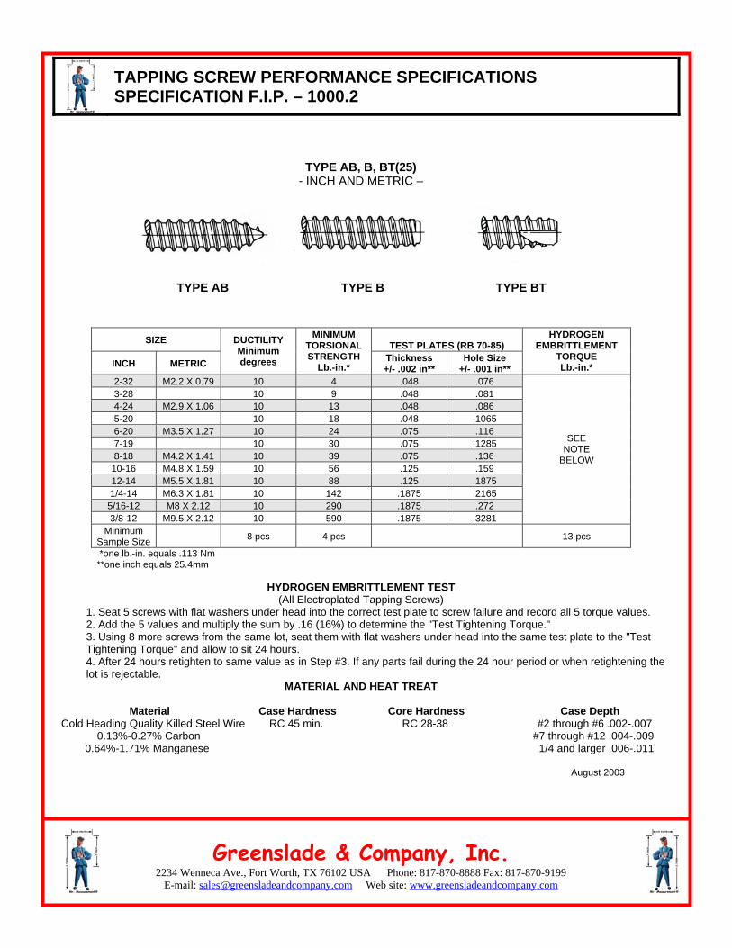
TYPE AB, B, BT(25) - INCH AND METRIC –
TYPE AB
TYPE B
TYPE BT
SIZE TEST PLATES (RB 70-85)
INCH METRIC
DUCTILITY Minimum degrees
MINIMUM TORSIONAL STRENGTH
Lb.-in.* Thickness +/- .002 in**
Hole Size +/- .001 in**
HYDROGEN EMBRITTLEMENT
TORQUE Lb.-in.*
2-32 M2.2 X 0.79 10 4 .048 .076 3-28 10 9 .048 .081 4-24 M2.9 X 1.06 10 13 .048 .086 5-20 10 18 .048 .1065 6-20 M3.5 X 1.27 10 24 .075 .116 7-19 10 30 .075 .1285 8-18 M4.2 X 1.41 10 39 .075 .136
10-16 M4.8 X 1.59 10 56 .125 .159 12-14 M5.5 X 1.81 10 88 .125 .1875 1/4-14 M6.3 X 1.81 10 142 .1875 .2165
5/16-12 M8 X 2.12 10 290 .1875 .272 3/8-12 M9.5 X 2.12 10 590 .1875 .3281
SEE NOTE
BELOW
Minimum Sample Size 8 pcs 4 pcs 13 pcs
*one lb.-in. equals .113 Nm **one inch equals 25.4mm
HYDROGEN EMBRITTLEMENT TEST (All Electroplated Tapping Screws)
1. Seat 5 screws with flat washers under head into the correct test plate to screw failure and record all 5 torque values. 2. Add the 5 values and multiply the sum by .16 (16%) to determine the "Test Tightening Torque." 3. Using 8 more screws from the same lot, seat them with flat washers under head into the same test plate to the "Test Tightening Torque" and allow to sit 24 hours. 4. After 24 hours retighten to same value as in Step #3. If any parts fail during the 24 hour period or when retightening the lot is rejectable.
MATERIAL AND HEAT TREAT
Material Case Hardness Core Hardness Case Depth Cold Heading Quality Killed Steel Wire RC 45 min. RC 28-38 #2 through #6 .002-.007 0.13%-0.27% Carbon #7 through #12 .004-.009 0.64%-1.71% Manganese 1/4 and larger .006-.011
August 2003
2234 Wenneca Ave., Fort Worth, TX 76102 USA Phone: 817-870-8888 Fax: 817-870-9199 E-mail: [email protected]
Greenslade & Company, Inc. Web site: www.greensladeandcompany.com
TAPPING SCREW PERFORMANCE SPECIFICATIONS SPECIFICATION F.I.P. – 1000.3
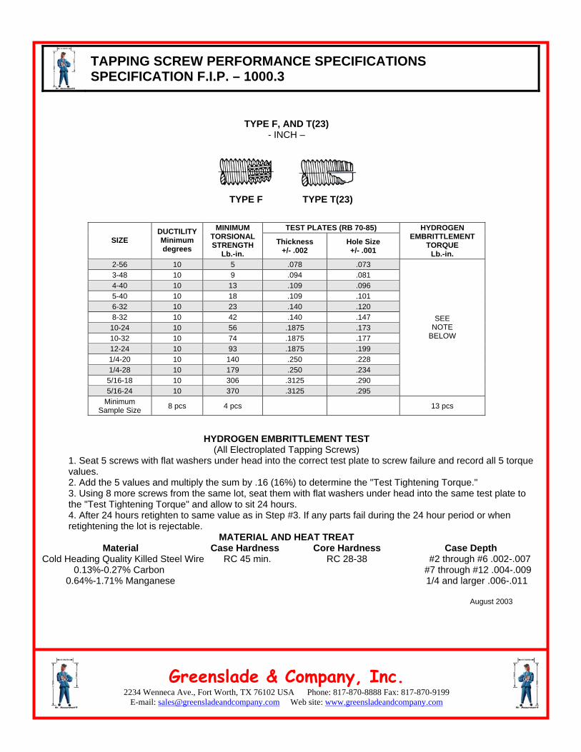
TYPE F, AND T(23) - INCH –
TYPE F
TYPE T(23)
TEST PLATES (RB 70-85) SIZE
DUCTILITY Minimum degrees
MINIMUM TORSIONAL STRENGTH
Lb.-in. Thickness
+/- .002 Hole Size +/- .001
HYDROGEN EMBRITTLEMENT
TORQUE Lb.-in.
2-56 10 5 .078 .073 3-48 10 9 .094 .081 4-40 10 13 .109 .096 5-40 10 18 .109 .101 6-32 10 23 .140 .120 8-32 10 42 .140 .147
10-24 10 56 .1875 .173 10-32 10 74 .1875 .177 12-24 10 93 .1875 .199 1/4-20 10 140 .250 .228 1/4-28 10 179 .250 .234
5/16-18 10 306 .3125 .290 5/16-24 10 370 .3125 .295
SEE NOTE
BELOW
Minimum Sample Size 8 pcs 4 pcs 13 pcs
HYDROGEN EMBRITTLEMENT TEST (All Electroplated Tapping Screws)
1. Seat 5 screws with flat washers under head into the correct test plate to screw failure and record all 5 torque values. 2. Add the 5 values and multiply the sum by .16 (16%) to determine the "Test Tightening Torque." 3. Using 8 more screws from the same lot, seat them with flat washers under head into the same test plate to the "Test Tightening Torque" and allow to sit 24 hours. 4. After 24 hours retighten to same value as in Step #3. If any parts fail during the 24 hour period or when retightening the lot is rejectable.
MATERIAL AND HEAT TREAT Material Case Hardness Core Hardness Case Depth
Cold Heading Quality Killed Steel Wire RC 45 min. RC 28-38 #2 through #6 .002-.007 0.13%-0.27% Carbon #7 through #12 .004-.009 0.64%-1.71% Manganese 1/4 and larger .006-.011 August 2003
2234 Wenneca Ave., Fort Worth, TX 76102 USA Phone: 817-870-8888 Fax: 817-870-9199 E-mail: [email protected]
Greenslade & Company, Inc. Web site: www.greensladeandcompany.com
TAPPING SCREW PERFORMANCE SPECIFICATIONS SPECIFICATION F.I.P. – 1000.4
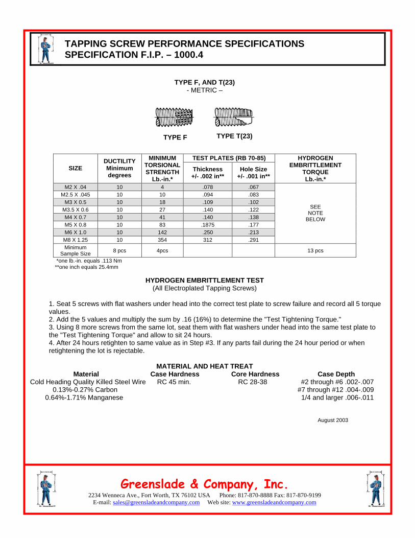
TYPE F, AND T(23) - METRIC –
TYPE F
TYPE T(23)
TEST PLATES (RB 70-85) SIZE
DUCTILITY Minimum degrees
MINIMUM TORSIONALSTRENGTH
Lb.-in.* Thickness +/- .002 in**
Hole Size +/- .001 in**
HYDROGEN EMBRITTLEMENT
TORQUE Lb.-in.*
M2 X .04 10 4 .078 .067 M2.5 X .045 10 10 .094 .083
M3 X 0.5 10 18 .109 .102 M3.5 X 0.6 10 27 .140 .122 M4 X 0.7 10 41 .140 .138 M5 X 0.8 10 83 .1875 .177 M6 X 1.0 10 142 .250 .213
M8 X 1.25 10 354 312 .291
SEE NOTE
BELOW
Minimum Sample Size 8 pcs 4pcs 13 pcs
*one lb.-in. equals .113 Nm **one inch equals 25.4mm
HYDROGEN EMBRITTLEMENT TEST
(All Electroplated Tapping Screws)
1. Seat 5 screws with flat washers under head into the correct test plate to screw failure and record all 5 torque values. 2. Add the 5 values and multiply the sum by .16 (16%) to determine the "Test Tightening Torque." 3. Using 8 more screws from the same lot, seat them with flat washers under head into the same test plate to the "Test Tightening Torque" and allow to sit 24 hours. 4. After 24 hours retighten to same value as in Step #3. If any parts fail during the 24 hour period or when retightening the lot is rejectable.
MATERIAL AND HEAT TREAT Material Case Hardness Core Hardness Case Depth
Cold Heading Quality Killed Steel Wire RC 45 min. RC 28-38 #2 through #6 .002-.007 0.13%-0.27% Carbon #7 through #12 .004-.009 0.64%-1.71% Manganese 1/4 and larger .006-.011
August 2003
2234 Wenneca Ave., Fort Worth, TX 76102 USA Phone: 817-870-8888 Fax: 817-870-9199 E-mail: [email protected]
Greenslade & Company, Inc. Web site: www.greensladeandcompany.com
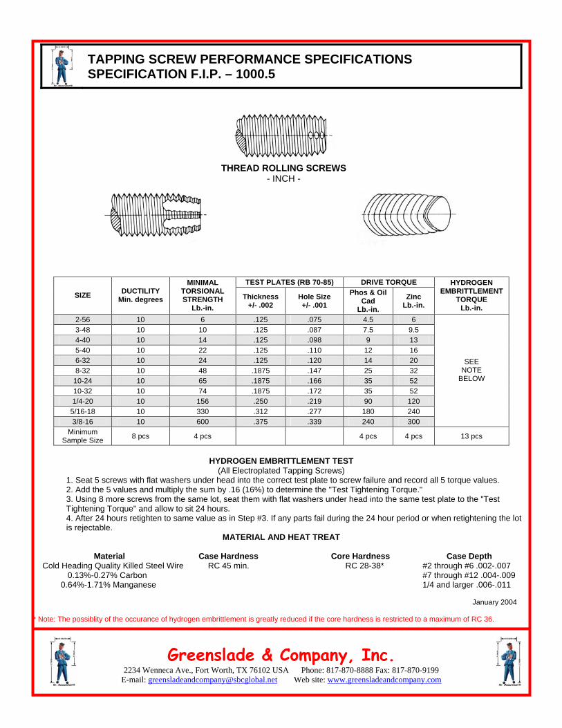
TAPPING SCREW PERFORMANCE SPECIFICATIONS SPECIFICATION F.I.P. – 1000.5
THREAD ROLLING SCREWS - INCH -
TEST PLATES (RB 70-85) DRIVE TORQUE
SIZE DUCTILITY Min. degrees
MINIMAL TORSIONAL STRENGTH
Lb.-in. Thickness
+/- .002 Hole Size +/- .001
Phos & Oil Cad
Lb.-in.
Zinc Lb.-in.
HYDROGEN EMBRITTLEMENT
TORQUE Lb.-in.
2-56 10 6 .125 .075 4.5 6 3-48 10 10 .125 .087 7.5 9.5 4-40 10 14 .125 .098 9 13 5-40 10 22 .125 .110 12 16 6-32 10 24 .125 .120 14 20 8-32 10 48 .1875 .147 25 32
10-24 10 65 .1875 .166 35 52 10-32 10 74 .1875 .172 35 52 1/4-20 10 156 .250 .219 90 120
5/16-18 10 330 .312 .277 180 240 3/8-16 10 600 .375 .339 240 300
SEE NOTE
BELOW
Minimum Sample Size 8 pcs 4 pcs 4 pcs 4 pcs 13 pcs
HYDROGEN EMBRITTLEMENT TEST
(All Electroplated Tapping Screws) 1. Seat 5 screws with flat washers under head into the correct test plate to screw failure and record all 5 torque values. 2. Add the 5 values and multiply the sum by .16 (16%) to determine the "Test Tightening Torque." 3. Using 8 more screws from the same lot, seat them with flat washers under head into the same test plate to the "Test Tightening Torque" and allow to sit 24 hours. 4. After 24 hours retighten to same value as in Step #3. If any parts fail during the 24 hour period or when retightening the lot is rejectable.
MATERIAL AND HEAT TREAT
Material Case Hardness Core Hardness Case Depth Cold Heading Quality Killed Steel Wire RC 45 min. RC 28-38* #2 through #6 .002-.007 0.13%-0.27% Carbon #7 through #12 .004-.009 0.64%-1.71% Manganese 1/4 and larger .006-.011 January 2004 * Note: The possiblity of the occurance of hydrogen embrittlement is greatly reduced if the core hardness is restricted to a maximum of RC 36.
2234 Wenneca Ave., Fort Worth, TX 76102 USA Phone: 817-870-8888 Fax: 817-870-9199 E-mail: [email protected]
Greenslade & Company, Inc. Web site: www.greensladeandcompany.com
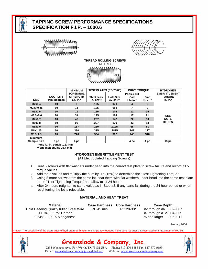
TAPPING SCREW PERFORMANCE SPECIFICATIONS SPECIFICATION F.I.P. – 1000.6
THREAD ROLLING SCREWS
- METRIC -
TEST PLATES (RB 70-85) DRIVE TORQUE
SIZE DUCTILITY
Min. degrees
MINIMUM TORSIONAL STRENGTH
Lb.-in.* Thickness +/- .002**
Hole Size +/- .001**
Phos & Oil Cad
Lb.-in.* Zinc
Lb.-in.*
HYDROGEN EMBRITTLEMENT
TORQUE lb.-in.*
M2x0.4 10 6 .125 .070 4 5 M2.5x0.45 10 11 .125 .088 7 9
M3x0.5 10 19 .125 .106 11 15 M3.5x0.6 10 31 .125 .124 17 21 M4x0.7 10 46 .207 .142 22 30 M5x0.8 10 93 .207 .179 42 53 M6x1.0 10 157 .250 .2125 66 81
M8x1.25 10 380 .315 .2875 142 177 M10x1.5 10 770 .394 .362 248 310
SEE NOTE
BELOW
Minimum Sample Size 8 pc 4 pc 4 pc 4 pc 13 pc
* one lb.-in. equals .113 Nm ** one inch equals 25.4 mm
HYDROGEN EMBRITTLEMENT TEST (All Electroplated Tapping Screws)
1. Seat 5 screws with flat washers under head into the correct test plate to screw failure and record all 5
torque values. 2. Add the 5 values and multiply the sum by .16 (16%) to determine the "Test Tightening Torque." 3. Using 8 more screws from the same lot, seat them with flat washers under head into the same test plate
to the "Test Tightening Torque" and allow to sit 24 hours. 4. After 24 hours retighten to same value as in Step #3. If any parts fail during the 24 hour period or when
retightening the lot is rejectable.
MATERIAL AND HEAT TREAT
Material Case Hardness Core Hardness Case Depth Cold Heading Quality Killed Steel Wire
0.13% - 0.27% Carbon 0.64% - 1.71% Manganese
RC 45 min. RC 28-38* #2 through #6 .002-.007 #7 through #12 .004-.009 ¼ and larger .006-.011
January 2004
* Note: The possiblity of the occurance of hydrogen embrittlement is greatly reduced if the core hardness is restricted to a maximum of RC 36.
2234 Wenneca Ave., Fort Worth, TX 76102 USA Phone: 817-870-8888 Fax: 817-870-9199 E-mail: [email protected]
Greenslade & Company, Inc. Web site: www.greensladeandcompany.com
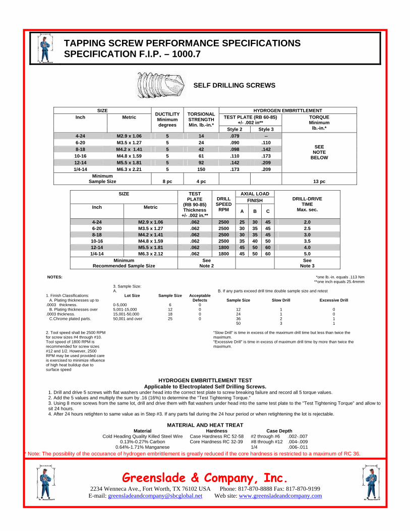
TAPPING SCREW PERFORMANCE SPECIFICATIONS SPECIFICATION F.I.P. – 1000.7
SELF DRILLING SCREWS
SIZE HYDROGEN EMBRITTLEMENT
TEST PLATE (RB 60-85) +/- .002 in**
Inch Metric DUCTILITY Minimum degrees
TORSIONAL STRENGTH Min. lb.-in.*
Style 2 Style 3
TORQUE Minimum
lb.-in.* 4-24 M2.9 x 1.06 5 14 .079 -- 6-20 M3.5 x 1.27 5 24 .090 .110 8-18 M4.2 x 1.41 5 42 .098 .142 10-16 M4.8 x 1.59 5 61 .110 .173 12-14 M5.5 x 1.81 5 92 .142 .209 1/4-14 M6.3 x 2.21 5 150 .173 .209
SEE NOTE
BELOW
Minimum Sample Size 8 pc 4 pc 13 pc
AXIAL LOAD SIZE
FINISH Inch Metric
TEST PLATE
(RB 90-85) Thickness
+/- .002 in.**
DRILL SPEED
RPM A B C
DRILL-DRIVE TIME
Max. sec.
4-24 M2.9 x 1.06 .062 2500 25 30 45 2.0 6-20 M3.5 x 1.27 .062 2500 30 35 45 2.5 8-18 M4.2 x 1.41 .062 2500 30 35 45 3.0
10-16 M4.8 x 1.59 .062 2500 35 40 50 3.5 12-14 M5.5 x 1.81 .062 1800 45 50 60 4.0 1/4-14 M6.3 x 2.12 .062 1800 45 50 60 5.0
Minimum Recommended Sample Size
See Note 2
See Note 3
NOTES:
*one lb.-in. equals .113 Nm **one inch equals 25.4mmm
3. Sample Size: A.
B. If any parts exceed drill time double sample size and retest
1. Finish Classifications: A. Plating thicknesses up to .0003 thickness. B. Plating thicknesses over .0003 thickness. C.Chrome plated parts.
Lot Size
0-5,000 5,001-15,000 15,001-50,000 50,001 and over
Sample Size
6 12 18 25
Acceptable Defects
0 0 0 0
Sample Size
12 24 36 50
Slow Drill
1 1 2 3
Excessive Drill
0 0 1 1
2. Tool speed shall be 2500 RPM for screw sizes #4 through #10. Tool speed of 1800 RPM is recommended for screw sizes #12 and 1/2. However, 2500 RPM may be used provided care is exercised to minimize nfluence of high heat buildup due to surface speed
"Slow Drill" is time in excess of the maximum drill time but less than twice the maximum. "Excessive Drill" is time in excess of maximum drill time by more than twice the maximum.
HYDROGEN EMBRITTLEMENT TEST
Applicable to Electroplated Self Drilling Screws. 1. Drill and drive 5 screws with flat washers under head into the correct test plate to screw breaking failure and record all 5 torque values. 2. Add the 5 values and multiply the sum by .16 (16%) to determine the "Test Tightening Torque." 3. Using 8 more screws from the same lot, drill and drive them with flat washers under head into the same test plate to the "Test Tightening Torque" and allow to sit 24 hours. 4. After 24 hours retighten to same value as in Step #3. If any parts fail during the 24 hour period or when retightening the lot is rejectable.
MATERIAL AND HEAT TREAT
Material Cold Heading Quality Killed Steel Wire
0.13%-0.27% Carbon 0.64%-1.71% Manganese
Hardness Case Hardness RC 52-58 Core Hardness RC 32-39
Case Depth #2 through #6 .002-.007 #8 through #12 .004-.009 1/4 .006-.011
* Note: The possiblity of the occurance of hydrogen embrittlement is greatly reduced if the core hardness is restricted to a maximum of RC 36.
2234 Wenneca Ave., Fort Worth, TX 76102 USA Phone: 817-870-8888 Fax: 817-870-9199 E-mail: [email protected]
Greenslade & Company, Inc. Web site: www.greensladeandcompany.com
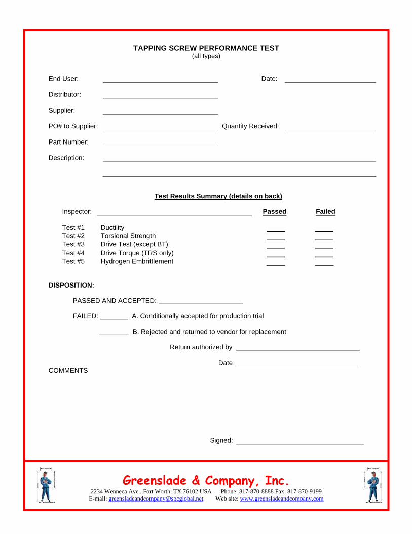
TAPPING SCREW PERFORMANCE TEST (all types)
End User:
Date:
Distributor:
Supplier:
PO# to Supplier:
Quantity Received:
Part Number:
Description:
Test Results Summary (details on back)
Inspector: Passed Failed Test #1
Ductility
Test #2 Torsional Strength Test #3 Drive Test (except BT) Test #4 Drive Torque (TRS only) Test #5 Hydrogen Embrittlement
DISPOSITION:
PASSED AND ACCEPTED: FAILED: A. Conditionally accepted for production trial B. Rejected and returned to vendor for replacement
Return authorized by
Date
COMMENTS
Signed:
2234 Wenneca Ave., Fort Worth, TX 76102 USA Phone: 817-870-8888 Fax: 817-870-9199 E-mail: [email protected]
Greenslade & Company, Inc. Web site: www.greensladeandcompany.com
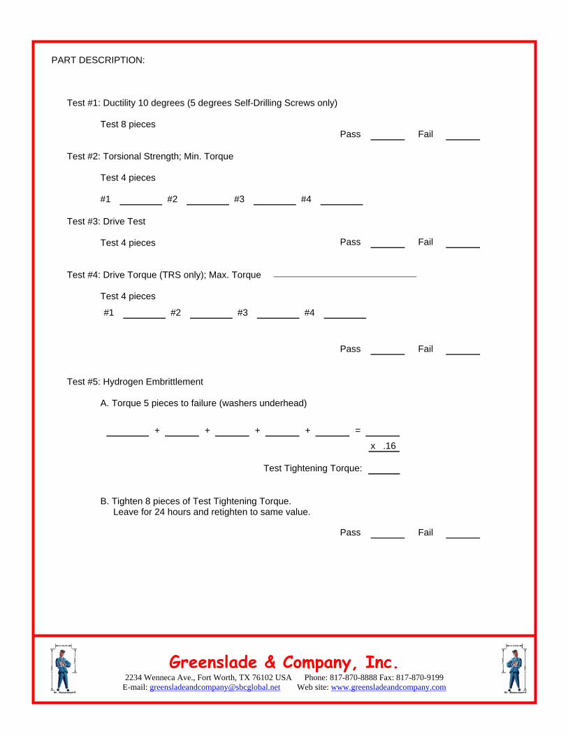
PART DESCRIPTION:
Test #1: Ductility 10 degrees (5 degrees Self-Drilling Screws only)
Test 8 pieces Pass Fail
Test #2: Torsional Strength; Min. Torque
Test 4 pieces #1 #2 #3 #4
Test #3: Drive Test
Pass Fail Test 4 pieces
Test #4: Drive Torque (TRS only); Max. Torque
Test 4 pieces #1 #2 #3 #4
Pass Fail
Test #5: Hydrogen Embrittlement
A. Torque 5 pieces to failure (washers underhead)
x .16
Test Tightening Torque:
+ + + + =
B. Tighten 8 pieces of Test Tightening Torque. Leave for 24 hours and retighten to same value.
Pass Fail
2234 Wenneca Ave., Fort Worth, TX 76102 USA Phone: 817-870-8888 Fax: 817-870-9199 E-mail: [email protected]
Greenslade & Company, Inc. Web site: www.greensladeandcompany.com
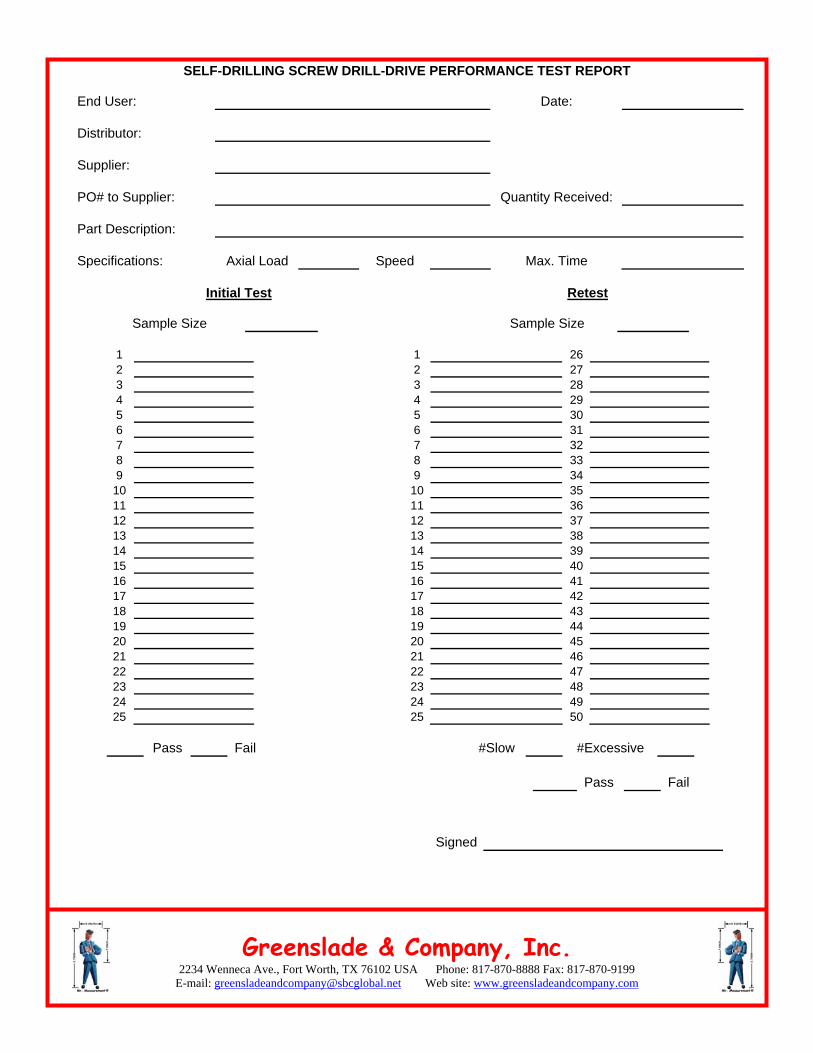
SELF-DRILLING SCREW DRILL-DRIVE PERFORMANCE TEST REPORT
End User: Date: Distributor:
Supplier:
PO# to Supplier:
Quantity Received:
Part Description:
Specifications:
Axial Load
Speed
Max. Time
Initial Test Retest
Sample Size Sample Size
1 1 26 2 2 27 3 3 28 4 4 29 5 5 30 6 6 31 7 7 32 8 8 33 9 9 34 10 10 35 11 11 36 12 12 37 13 13 38 14 14 39 15 15 40 16 16 41 17 17 42 18 18 43 19 19 44 20 20 45 21 21 46 22 22 47 23 23 48 24 24 49 25 25 50
Pass Fail #Slow #Excessive
Pass Fail Signed