Embed Size (px)
Citation preview
Edition 1998 PK-002
Tape-Wound Cores forMagnetic Amplifier Chokes
VITROVAC 6025 Z

VITROVAC 6025 ZTape-Wound Cores for Magnetic Amplifier Chokes
The world's first amorphous saturable reactor cores. Highly reliable and most efficient since 15 years.
Contents
Page1. General Info on the Mag Amp Principle 1
1.1 The Core Solution for Output Control 11.2 Cores from VAC 11.3 Basic Principle of Operation 1
2. Properties of VITROVAC 6025Z Cores 3
2.1 Magnetic Properties 32.2 Magnet Quality 32.3 Application Temperature Limit and
Temperature Characteristics 52.4 Core Design and Standard Sizes 62.5 Order Information 7
3. How to calculate a Mag Amp Choke 7
3.1 Selection of Core Size andNumber of Turns 7
3.2 Estimation of the Control Current 83.3 Example 8
4. Appendix 10
4.1 Core and Copper Losses in Theory 104.2 Notes on more Theoretical Fine Tuning 104.3 Notes on Regulation Circuits 11
5. Definition of Terms 12
6. Relevant Publications 13
1.1 The Core Solution for Output ControlThe magnetic amplifier (Mag Amp) control technique hasbecome the synonym for reliability in the old 50 Hz days andstill is in modern switched-mode power supplies. Nowadays,Mag Amps are mainly used in switched-mode power supplieswith multiple outputs to control the output voltages. Push -pull, forward and - more recently - fly-back converter principleswith Mag Amp regulation have become established.
In most power supplies only one secondary output voltage isregulated closed-loop to the primary, other secondariesremain open-loop. The dynamic properties of these outputsare determined by the load and the primary switch. To controlvarious different output voltages, independently from oneanother, different regulation principles are used. Conventionallinear regulators reduce efficiency and are often limited tooutput currents of one or two amperes. Electronic regulatorsare more efficient but require more parts in the circuitry andare therefore more expensive and less reliable.
The Mag Amp regulation principle offers a low cost, efficientand, owing to the simple design, reliable solution to theseproblems. It meets the increasing demands on modernswitched-mode power supplies excellently. An efficiency levelof more than 90% can be realized even at higher switchingfrequencies. The low RF interference level is advantageous tothe suppression filter.
The most popular and particularly economic magneticamplifiers are those with a performance range from approx.20 to above 150 W per output, for currents between approx. 1and 30 A. With the new generation of ultracompact lowvoltage ICs (2.9 V, 3.3 V) suitable small Mag Amp cores areavailable at attractive prices.
The heart of a Mag Amp-choke is a toroidal core made froma soft-magnetic alloy with rectangular hysteresis loop and, inmost cases, just one winding for operation and controlcurrents. The specification requirements with regard to chokematerial are very high. In addition to low magnetic reversallosses (effect on heat build-up, control current, efficiency), amarkedly rectangular hysteresis loop featuring highremanence (effect on control range) and good saturationbehaviour is required. For this reason, amorphous Co-basedalloys such as VITROVAC 6025 Z have been acceptedworldwide as ideal materials for this application.
The function of the Mag Amp can be described as a highspeed on/off switch similar to a switching transistor. Therectangular B-H loop is causally related to two operatingstates. The switch is open as long as the choke ismagnetized and the current flow to the output is blocked. Assoon as the core material is saturated, the switch is on andcurrent starts to flow to the output. This effect is based on arapid change in impedance IZI (or inductivity L orpermeability µ) of the choke across 3-4 orders of magnitudewhen going into saturated condition.
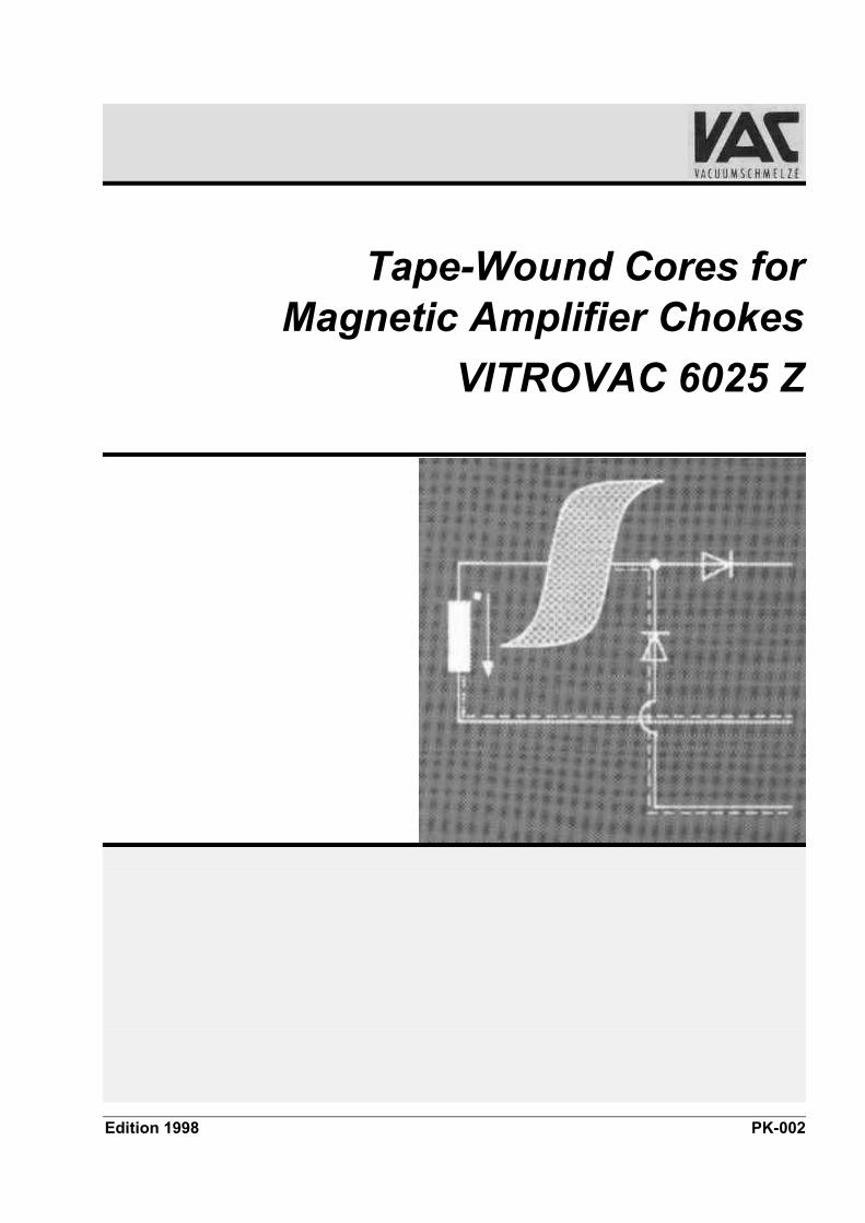
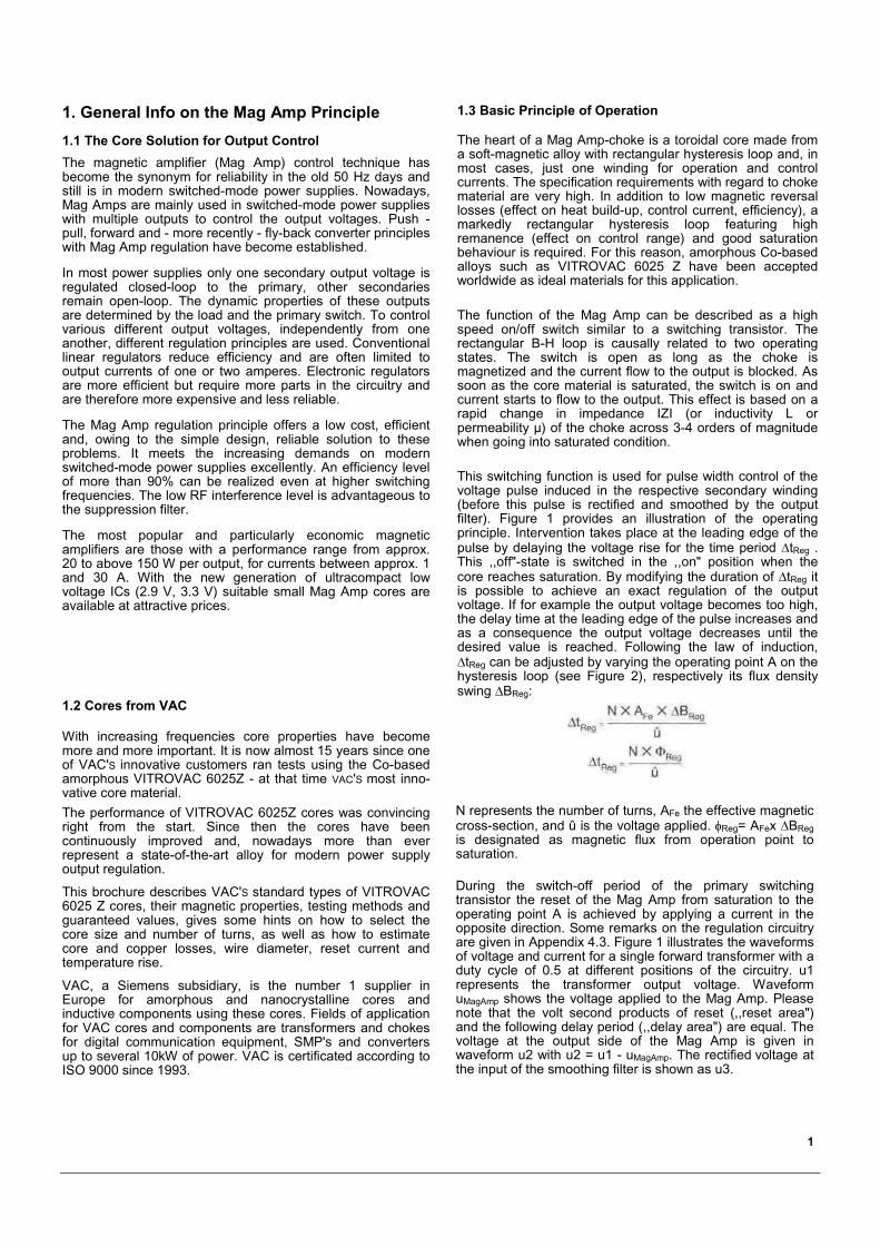
This switching function is used for pulse width control of thevoltage pulse induced in the respective secondary winding(before this pulse is rectified and smoothed by the outputfilter). Figure 1 provides an illustration of the operatingprinciple. Intervention takes place at the leading edge of thepulse by delaying the voltage rise for the time period �tReg .This ,,off"-state is switched in the ,,on" position when thecore reaches saturation. By modifying the duration of �tReg itis possible to achieve an exact regulation of the outputvoltage. If for example the output voltage becomes too high,the delay time at the leading edge of the pulse increases andas a consequence the output voltage decreases until thedesired value is reached. Following the law of induction,�tReg can be adjusted by varying the operating point A on thehysteresis loop (see Figure 2), respectively its flux densityswing �BReg:
1.2 Cores from VAC
With increasing frequencies core properties have becomemore and more important. It is now almost 15 years since oneof VAC'S innovative customers ran tests using the Co-basedamorphous VITROVAC 6025Z - at that time VAC'S most inno-vative core material.The performance of VITROVAC 6025Z cores was convincingright from the start. Since then the cores have beencontinuously improved and, nowadays more than everrepresent a state-of-the-art alloy for modern power supplyoutput regulation.
This brochure describes VAC'S standard types of VITROVAC6025 Z cores, their magnetic properties, testing methods andguaranteed values, gives some hints on how to select thecore size and number of turns, as well as how to estimatecore and copper losses, wire diameter, reset current andtemperature rise.
VAC, a Siemens subsidiary, is the number 1 supplier inEurope for amorphous and nanocrystalline cores andinductive components using these cores. Fields of applicationfor VAC cores and components are transformers and chokesfor digital communication equipment, SMP's and convertersup to several 10kW of power. VAC is certificated according toISO 9000 since 1993.
N represents the number of turns, AFe the effective magneticcross-section, and û is the voltage applied. �Reg= AFex �BRegis designated as magnetic flux from operation point tosaturation.
During the switch-off period of the primary switchingtransistor the reset of the Mag Amp from saturation to theoperating point A is achieved by applying a current in theopposite direction. Some remarks on the regulation circuitryare given in Appendix 4.3. Figure 1 illustrates the waveformsof voltage and current for a single forward transformer with aduty cycle of 0.5 at different positions of the circuitry. u1represents the transformer output voltage. WaveformuMagAmp shows the voltage applied to the Mag Amp. Pleasenote that the volt second products of reset (,,reset area")and the following delay period (,,delay area") are equal. Thevoltage at the output side of the Mag Amp is given inwaveform u2 with u2 = u1 - uMagAmp. The rectified voltage atthe input of the smoothing filter is shown as u3.
1
1. General Info on the Mag Amp Principle 1.3 Basic Principle of Operation

Figure 1: Basic Operating Principle of Magnetic Amplifier Regulation
2
The "dead time" defined as �tdead in Figure 1 occurs due tothe non-ideal characteristics of real magnetic materialsregarding the difference between remanence and saturation(even if, e.g., amorphous metals have already come veryclose to this ideal). The magnetic core will always bemagnetized from remanence to saturation even if no controlcurrent is applied. During this period the voltage is blocked.
Dead time is dependent on remanence flux density swing�Brs and, of course, on the magnetic cross-section andnumber of turns. Naturally, this additional voltage dropneeds to be taken into account when defining the transmitteroutput voltage. The latter has a major influence on thedesign of the choke, i.e. cross-section and number of turns.
Figure 2: Operating on the B-H Loop of the Magnetic Core
2. Properties of VITROVAC 6025 Z Cores
2.1 Magnetic Properties
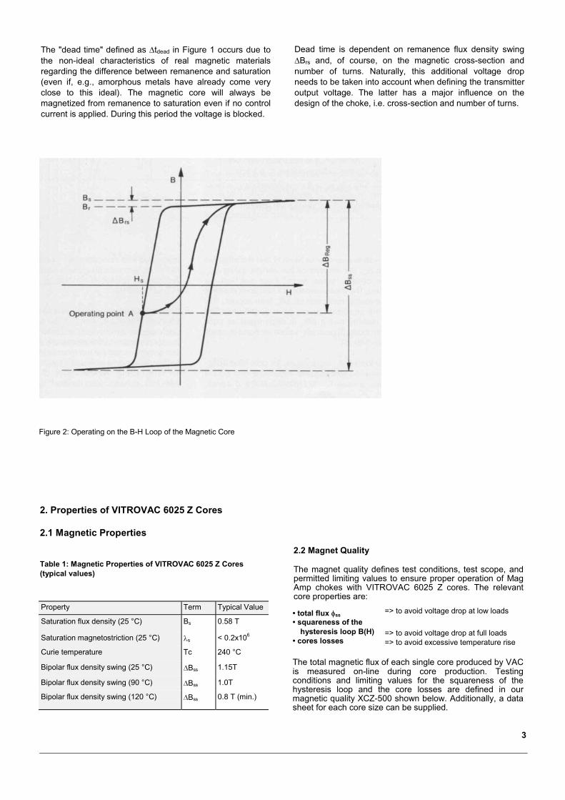
Table 1: Magnetic Properties of VITROVAC 6025 Z Cores(typical values)
2.2 Magnet Quality
The magnet quality defines test conditions, test scope, andpermitted limiting values to ensure proper operation of MagAmp chokes with VITROVAC 6025 Z cores. The relevantcore properties are:
Property Term Typical Value
Saturation flux density (25 °C) Bs 0.58 T
Saturation magnetostriction (25 °C) �s < 0.2x10⁶
Curie temperature Tc 240 °C
Bipolar flux density swing (25 °C) �Bss 1.15T
Bipolar flux density swing (90 °C) �Bss 1.0T
Bipolar flux density swing (120 °C) �Bss 0.8 T (min.)
=> to avoid voltage drop at low loads
=> to avoid voltage drop at full loads=> to avoid excessive temperature rise
The total magnetic flux of each single core produced by VACis measured on-line during core production. Testingconditions and limiting values for the squareness of thehysteresis loop and the core losses are defined in ourmagnetic quality XCZ-500 shown below. Additionally, a datasheet for each core size can be supplied.
3
• total flux �ss• squareness of the
hysteresis loop B(H)• cores losses
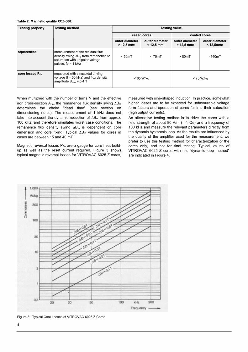
Table 2: Magnetic quality XCZ-500:
Testing value
cased cores coated cores
Testing property Testing method
outer diameter> 12,5 mm:
outer diameter< 12,5 mm:
outer diameter> 12,5 mm:
outer diameter< 12,5mm:
squareness measurement of the residual fluxdensity swing �Brs from remanence tosaturation with unipolar voltagepulses, fp = 1 kHz
< 50mT < 75mT <80mT <140mT
core losses PFe measured with sinusoidal drivingvoltage (f = 50 kHz) and flux densityamplitude Bmax = 0.4 T
< 65 W/kg < 75 W/kg
When multiplied with the number of turns N and the effectiveiron cross-section AFe, the remanence flux density swing �Brs
determines the choke "dead time" (see section ondimensioning notes). The measurement at 1 kHz does nottake into account the dynamic reduction of �Brs from approx.100 kHz, and therefore simulates worst case conditions. Theremanence flux density swing �Brs is dependent on coredimension and core fixing. Typical �Brs values for cores incases are between 15 and 40 mT
Magnetic reversal losses PFe are a gauge for core heat build-up as well as the reset current required. Figure 3 showstypical magnetic reversal losses for VITROVAC 6025 Z cores,
measured with sine-shaped induction. In practice, somewhathigher losses are to be expected for unfavourable voltageform factors and operation of cores far into their saturation(high output currents).An alternative testing method is to drive the cores with afield strength of about 80 A/m (= 1 Oe) and a frequency of100 kHz and measure the relevant parameters directly fromthe dynamic hysteresis loop. As the results are influenced bythe quality of the amplifier used for the measurement, weprefer to use this testing method for characterization of thecores only, and not for final testing. Typical values ofVITROVAC 6025 Z cores with this “dynamic loop method"are indicated in Figure 4.
Figure 3: Typical Core Losses of VITROVAC 6025 Z Cores
4
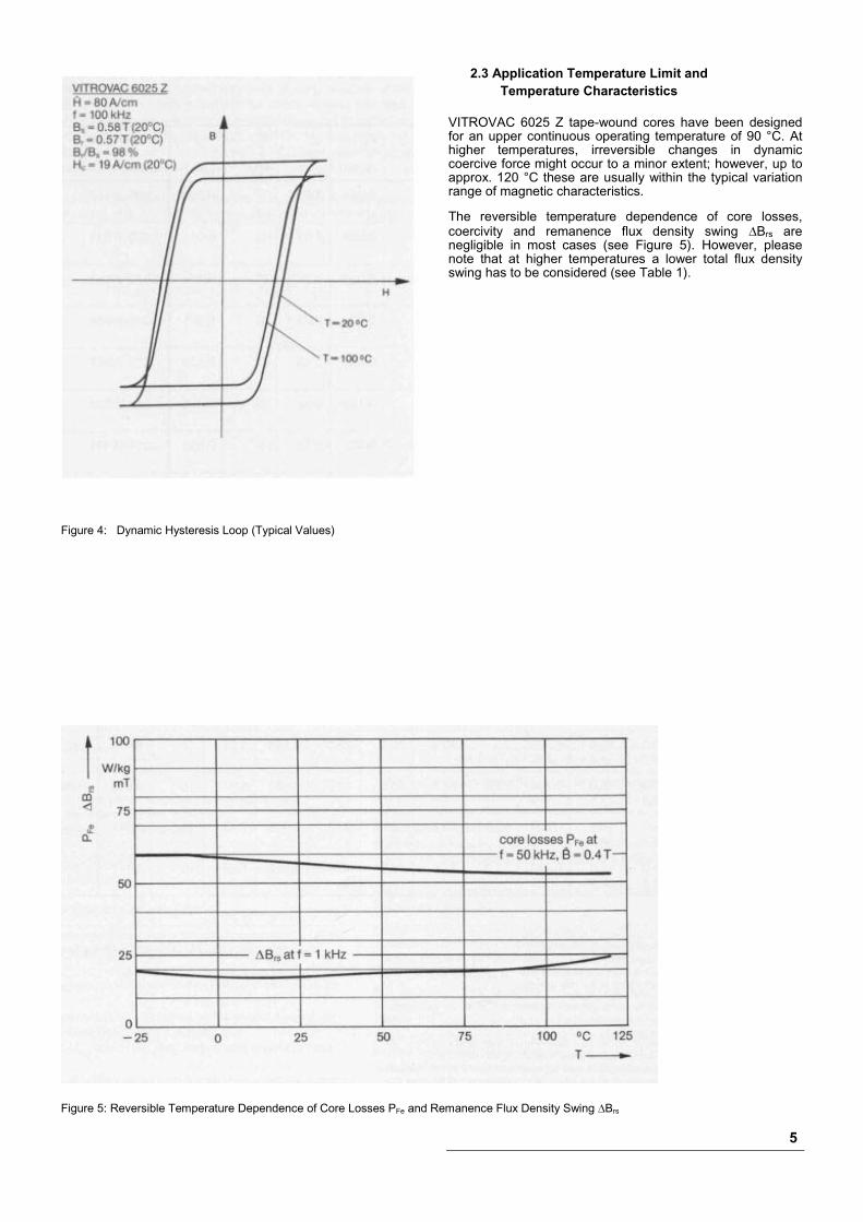
2.3 Application Temperature Limit andTemperature Characteristics
VITROVAC 6025 Z tape-wound cores have been designedfor an upper continuous operating temperature of 90 °C. Athigher temperatures, irreversible changes in dynamiccoercive force might occur to a minor extent; however, up toapprox. 120 °C these are usually within the typical variationrange of magnetic characteristics.
The reversible temperature dependence of core losses,coercivity and remanence flux density swing �Brs arenegligible in most cases (see Figure 5). However, pleasenote that at higher temperatures a lower total flux densityswing has to be considered (see Table 1).
Figure 4: Dynamic Hysteresis Loop (Typical Values)
Figure 5: Reversible Temperature Dependence of Core Losses PFe and Remanence Flux Density Swing �Brs
5

2.4 Core Design and Standard Sizes
Table 3: VITROVAC 6025 Z cores for Mag Amps, standard sizes, Fix 022
d1
D1
mm
d2
D2
mm
h1
H1
mm
AFe
cm2IFe
cmmFe
g�ss
(25°C)µWb
�ss,min(90°C)µWb
ACu
cm2lCu
cmRth
K/WWaxAFe
cm4part numberT60006-E4
8.09.7
4.63.1
4.05.1
0.054 1.98 0.8 6.2 5.4 0.019 1.91 79 0.004 ...008-W462
10.011.6
8.06.5
4.05.1
0.032 2.83 0.7 3.7 3.2 0.082 2.01 56 0.011 ...010-W534
10.111.6
6.95.5
4.56.0
0.058 2.67 1.2 6.7 5.8 0.059 2.24 57 0.014 ...010-W663
12.814.7
9.57.9
3.24.8
0.042 3.50 1.1 4.8 4.2 0.121 2.23 44 0.021 ...012-W464
12.014.0
8.06.6
4.56.2
0.072 3.14 1.7 8.3 7.2 0.085 2.45 47 0.025 ...012-W547
12.514.0
10.0 8.5
5.06.8
0.050 3.53 1.4 5.8 5.0 0.140 2.56 42 0.028 ...012-W535
14.015.5
8.06.5
4.55.7
0.108 3.46 2.9 12.4 10.8 0.082 2.53 44 0.036 ...014-W481
16.017.9
10.08.2
6.08.2
0.144 4.08 4.5 16.6 14.4 0.131 3.20 34 0.076 ...016-W536
17.519.1
12.510.9
6.08.1
0.120 4.71 4.4 13.8 12.0 0.231 3.30 30 0.112 ...017-W537
19.021.2
15.013.0
5.07.3
0.080 5.34 3.3 9.2 8.0 0.329 3.17 27 0.106 ...019-W539
19.021.2
15.013.0
10.012.3
0.160 5.34 6.6 18.4 16.0 0.329 4.25 24 0.212 ...019-W540
20.022.6
12.510.3
8.010.2
0.240 5.1 9.4 27.6 24.0 0.206 4.05 26 0.200 ...020-W538
25.027.9
16.013.6
10.012.5
0.360 6.44 17.9 41.4 36.0 0.360 4.96 19 0.523 ...025-W541
25.027.7
20.017.1
10.012.9
0.200 7.1 10.9 23.0 20.0 0.568 4.91 18 0.459 ...025-W542
30.032.8
20.017.6
10.012.5
0.400 7.85 24.2 46.0 40.0 0.602 5.37 16 0.973 ...030-W543
40.043.1
25.022.4
15.018.5
0.900 10.2 70.8 103.5 90.0 0.975 7.43 11 3.547 ...040-W544
40.043.3
32.028.8
15.018.3
0.480 11.3 41.8 55.2 48.0 1.612 7.30 10 3.127 ...040-W545
d1 = nominal external diameter of cored2 = nominal internal diameter of coreh1 = nominal height of coreD1 = maximal external diameter of caseD2 = minimal internal diameter of caseH1 = maximal height of caseAFe = effective iron cross-section in cm2
IFE = mean iron path length in cmmFe = core mass in gACu = effective copper cross-section in cm2 (calculated by using a
copper fill factor 0.33 and a remaining hole ratio of 0.5. Theremaining hole ratio is the internal diameter of the wound core(remaining hole) divided by the interior diameter of the case)
lCu = mean length of a copper turn in cmRth = heat transfer resistance of an open wound choke with
free convection in K/W
WaxAFe = core area product in cm4, used in some othermethods of Mag Amp choke design. Wa is theavailable winding area of the case in cm2
�ss = total flux in µWb with �ss = 2 x Bs x AFe.�ss, min = total flux in µWb (minimum value at 90°C)
Updated core range and most popular standard sizes can beseen under http://www.vacuumschmelze.com
6

The standard core sizes for Magnetic Amplifiers arepreferably supplied in plastic protective cases, addingsilicone rubber (Fix 022). This finish is suitable for directwinding and offers optimum mechanical protection for thecore, and thus the best magnetic properties. The resinsused for the core cases fulfil for the most part UL94V-0 (with130°C heat resistance), in particular cases UL94HB (with120°C heat resistance).
As a further type of finish we are able to offer an epoxy resincoating (Fix 350). Due to the reduction of the magnetic
properties this type of fixing is only to be recommended ifspecial core sizes are required.
2.5 Order Information
For your orders please use our part numbers as given inTable 3.In addition to the delivery of cores, we also offer thepossibility of purchasing already wound cores (components).You will find information on these in our product sheet PB-410-2.
3. How to calculate a Mag Amp ChokeAlthough the Mag Amp choke is a very simple inductivecomponent consisting of a core and some copper turns only,careful consideration of all influencing parameters isnecessary to achieve a cost optimized design without toohigh temperature rise of the choke.
variables:effective cross-section AFe (core size)number of turns N wire diameter dCuwinding area ACu
influencing factors:circuit designoutput voltage U1voltage drops in magnetic amplifier controlled circuitvoltage drops in main circuitpossibly: short-circuit-proof design
to be taken into account:magnetic core lossescopper lossesdead time" of magnetic amplifier choke
3.1 Selection of Core Size and Number of Turns
Starting parameters are
• the wire size (which is determined by the output current, forexample current density S = 4 A/mm2) and
• the voltage UReg which the Mag Amp choke should control.
UReg can be calculated for a given transformer outputvoltage û min where there are no short-circuit requirementsby:
UReg = � x �max x û min – U1
and for a short-circuit-proof design by:
UReg = � x �max x û min
�MAX is then the maximum duty cycle ratio of the primaryswitching transistor, � = 1 for forward converter principle, �= 2 for push-pull.
If the transformer voltage is not fixed, Appendix 4.2 givessome hints on how to find a suitable value.
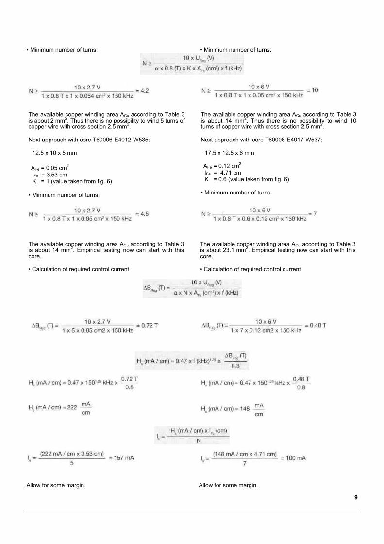
• The required number of turns can be calculated by:
K is a correction factor for �B to limit the temperature risedue to core losses (see Figure 6).
• start with a small core• increase core size, until the required number of turns can
easily be distributed around the core in a single layer.
Now “empirical optimization" can start. Here, the followingnotes may be helpful:• If the magnetic amplifier choke becomes too hot during
open circuit or short-circuit operation, iron losses are thereason. A solution is to increase either the iron cross-section AFe or the number of turns N.
• If excessive heat build-up in the choke during full loadoperation occurs, the copper losses are too high. In thiscase, the wire diameter has to be increased. The next coresize with a larger winding area is then perhaps necessary.
• “Too high" secondary voltages of the transformer causeexcessive full load operation losses. If this occurs thechoke will still need to correct this "excess" voltage, evenunder full load operating conditions, thus causingadditional losses. A correction of the turn ratio (if possible)can solve this problem. Please see also Appendix 4.2.
7
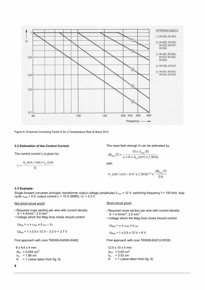
Figure 6: Empirical Correcting Factor K for a Temperature Rise of about 30 K
3.2 Estimation of the Control Current
The control current Is is given by:
The reset field strengh H can be estimated by:
with:
3.3 Example:Single forward converter principle; transformer output voltage (amplitude) û min = 12 V; switching frequency f = 150 kHz; dutycycle �max = 0.5; output current I1 = 10 A (RMS); U1 = 3.3 V.
Not short-circuit proof:
• Required cross section per wire with current densityS = 4 A/mm2: 2.5 mm2
• Voltage which the Mag Amp choke should control:
UReg = � x �max x û min – U1
UReg = 1 x 0.5 x 12 V – 3.3 V = 2.7 V
Short-circuit proof:
• Required cross section per wire with current densityS = 4 A/mm2: 2.5 mm2
• Voltage which the Mag Amp choke should control:
UReg = � x �max x û min
UReg = 1 x 0.5 x 12 V = 6 V
First approach with core T60006-E4008-W462:
8 x 4.6 x 4 mm
First approach with core T60006-E4012-W535:
12.5 x 10 x 5 mm
8
AFe = 0,054 cm2
lFe = 1.98 cmK = 1 (value taken from fig. 6)
AFe = 0,05 cm2
lFe = 3.53 cmK = 1 (value taken from fig. 6)
• Minimum number of turns: • Minimum number of turns:
The available copper winding area ACu according to Table 3is about 2 mm2. Thus there is no possibility to wind 5 turns ofcopper wire with cross section 2.5 mm2.
Next approach with core T60006-E4012-W535:
12.5 x 10 x 5 mm
AFe = 0.05 cm2
lFe = 3.53 cmK = 1 (value taken from fig. 6)
• Minimum number of turns:
The available copper winding area ACu according to Table 3is about 14 mm2. Thus there is no possibility to wind 10turns of copper wire with cross section 2.5 mm2.
Next approach with core T60006-E4017-W537:
17.5 x 12.5 x 6 mm
AFe = 0.12 cm2
lFe = 4.71 cmK = 0.6 (value taken from fig. 6)
• Minimum number of turns:
The available copper winding area ACu according to Table 3is about 14 mm2. Empirical testing now can start with thiscore.
• Calculation of required control current
The available copper winding area ACu according to Table 3is about 23.1 mm2. Empirical testing now can start with thiscore.
• Calculation of required control current
Allow for some margin. Allow for some margin.
9
4. Appendix
4.1 Core and Copper Losses in Theory
Before or in addition to experimental testing, the followingapproximation formula can be used to check thetemperature rise due to core and copper losses:
Core losses PFe (approximation):
PFe (W / kg) = 0.021 x f 2 x �BReg2 + 0.109 x f1.5 x �BReg
1.5
with f in kHz and �BReg in T.
Temperature rise �TFe:
�TFe (K) = Rth (K / W) x PFe (W / kg) x mFe (kg)
Copper losses PCu (approximation not considering skin andproximity effects):
Temperature rise �TCu:
lout is the maximum output current (direct current).Approximate values of the heat-transfer resistance of anopen wound choke Rth with regard to free convection arelisted in Table 3, as well as AFe, ACu, lFe, and lCu. The specificelectrical resistance of copper �Cu is given for T= 80-100 °Cas � = 2.3 µ�m.
The total losses will be smaller than the sum of magneticreversal losses and copper losses as in full load operation(maximum copper losses) the control current and thus �BRegand PFe will be particularly low. Theoretical definition of theworst case, i.e. the operating condition with maximum totallosses, is difficult; for this reason, we recommendproceeding empirically.
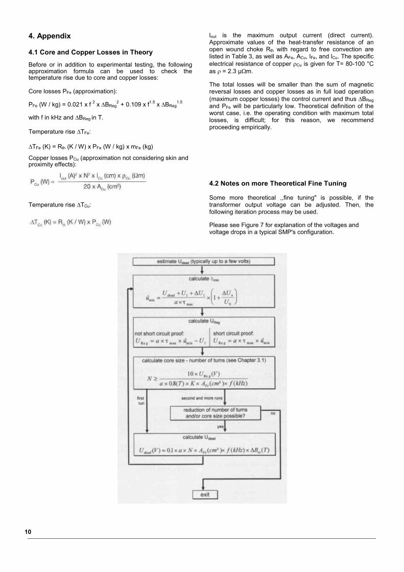
4.2 Notes on more Theoretical Fine Tuning
Some more theoretical ,,fine tuning" is possible, if thetransformer output voltage can be adjusted. Then, thefollowing iteration process may be used.
Please see Figure 7 for explanation of the voltages andvoltage drops in a typical SMP's configuration.
10
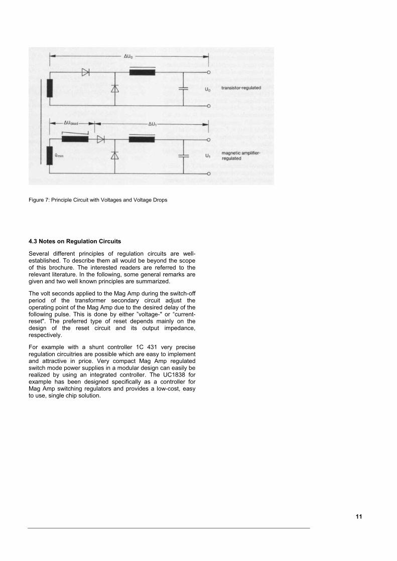
Figure 7: Principle Circuit with Voltages and Voltage Drops
4.3 Notes on Regulation Circuits
Several different principles of regulation circuits are well-established. To describe them all would be beyond the scopeof this brochure. The interested readers are referred to therelevant literature. In the following, some general remarks aregiven and two well known principles are summarized.
The volt seconds applied to the Mag Amp during the switch-offperiod of the transformer secondary circuit adjust theoperating point of the Mag Amp due to the desired delay of thefollowing pulse. This is done by either ”voltage-" or “current-reset". The preferred type of reset depends mainly on thedesign of the reset circuit and its output impedance,respectively.
For example with a shunt controller 1C 431 very preciseregulation circuitries are possible which are easy to implementand attractive in price. Very compact Mag Amp regulatedswitch mode power supplies in a modular design can easily berealized by using an integrated controller. The UC1838 forexample has been designed specifically as a controller forMag Amp switching regulators and provides a low-cost, easyto use, single chip solution.
11
5. Definition of Terms
AFe = effective iron cross-section in cm2
ACu = effective copper cross-section in cm2 (calculatedby using a copper filling factor 0.33 and aremaining hole ratio of 0.5. The remaining holeratio will be the internal diameter of the woundcore (remaining hole) divided by the interiordiameter of the case)
a = factor = 1 for single cycle feed forward converters,= 2 for push-pull feed forward converters
Bs = saturation inductionBr = remanence�BReg = the flux density swing in T corresponding to UReg�Bss = maximum flux density swing in T (recommended:
�Bss � 0.8 T)�Brs = remanence flux density swing in T (see magnetic
quality)�B = flux density amplitude (peak value) in T
d1 = nominal external diameter of unfixed core in mmd2 = nominal internal diameter of unfixed core in mmD1 = nominal external diameter of fixed core in mmD2 = nominal internal diameter of fixed core in mmf = frequency in kHzfp = pulse repetition frequency in kHzH1 = nominal height of fixed core in mmh1 = nominal height of unfixed core in mmHs = reset field strength in mA/cmIout = maximum output current (direct current) in AIs = control current in mAi1 = waveform of the current of the Mag Amp regulated
circuitK = correcting factor for taking into account magnetic
reversal and copper losses (see Figure 6)ICu = mean length of a copper winding in cmIFe = mean iron path length in cm�s = saturation magnetostrictionmFe = core mass in gN = number of turnsPFe = magnetic reversal losses of the core in W/kgPCu = copper losses of the winding in Wss = total flux in µWb with ss = 2 x Bs x AFess,min = total flux in µWb (minimum value at 120°C)Reg = magnetic flux corresponding to �BReg
�Cu = specific electrical resistance of copper (�Cu 2.27*10-5
�m at T = 80-100 °C)Rth = heat-transfer resistance of an open wound
choke with free convection in K/WS = max. permissible current density of wireTC = Curie temperature�TFe = maximum excess temperature of the core in K�TCu = maximum excess temperature of the winding
in K�tReg = delay time of the Mag Amp choke
corresponding to �BReg�tdead = dead time of the core corresponding to �Brs�max = maximum pulse duty ratio of the primary
switching transistorUReg = maximum voltage in V to be controlled by the
magnetic amplifier chokeU0 = nominal output voltage in V (Figure 1 and 7) of
main output (transistor regulated)U1 = nominal output voltage in V (Figure 1 and 7) of
magnetic amplifier regulated output�U0 = voltage drops in V (Figure 1 and 7) in main
circuit�U1 = voltage drops in V (Figure 1 and 7) in
magnetic amplifier-regulated circuit (withoutvoltage drop across the magnetic amplifierchoke)
�Udead = minimum voltage drop in V across magneticamplifier choke („dead time“)
û = transformer output voltage (peak value) for theMag Amp controlled output in V
ûmin = minimum value of ûu1 = waveform of the transformer output voltageu2 = waveform of the voltage at the output side of
the Mag Ampu3 = waveform of the input voltage of the
smoothing filteruMagAmp = waveform of the voltage applied to the Mag
Amp choke� = permeabilityWa*AFe = core area product in cm4, used in some other
methods of Mag Amp choke design. Wa is theavailable winding area of the case in cm2
Z = impedance
12
6. Relevant PublicationsR. Hiramatsu, K. Harada, T. Ninomiya, Switched Mode ConverterUsing High-Frequency Magnetic Amplifier, PowerconversionInternational, March-April 1980, S. 75-82
R. Hiramatsu, K. Harada, I. Sasada, A Magnetic Amplifier Controllerof Amorphous Cores for a 200 kHz Switching Regulator, IEEETransactions on Magnetics, Vol. Mag. 18. No. 6, 1982,S. 1764-1766
S. Takeda, K. Hasegawa, T. Yamada, Designing ImprovedSaturable Reactors Regulators with Amorphous Magnetic Materials,Proceedings of Powercon 9, 1982, C1-1, S. 1-12
M. Yamaguchi, K. Murakami, T. Kikuchi, High FrequencyCharacteristics of Amorphous Tape-Wound Cores Used forControlling a Switched-Mode Power Supply, Intelec 1983, Tokyo, S.400-407
T. Koyashiki, T. Okata, Design Considerations in Multi-Output DC-DC Converters with Magnetic Amplifiers, Intelec 1983, Tokyo, S.388-394
R.J. Taylor, Optimizing High Frequency Control Magamp Design,Proceedings of Powercon 10, 1983, A-1, S. 1-12
U. Schwarz, Multiple Output Switch Mode Power Supplies UsingSaturable Reactor Control, Intelec 1985, Munchen, S. 339-344
C.E. Mullett, R. Hiramatsu, An Improved Parallel Control Circuit forSaturable Reactor Output Regulators in High-Frequency Switched-Mode Converters, IEEE APEC Proceedings, April, 1986
C.E. Mullet, R.A. Mammano, Using an Integrated Controller in theDesign of Mag-Amp Output Regulators, Unitrode Application NoteU-109
K. Harada, T. Nabeshima, R. Hiramatsu, On the Control of MagneticAmplifiers for High Frequency DC to DC Converters, IEEETransactions on Power Electronics, Vol. PE-2, No.#, July 1987
C.E. Mullet, R. Hiramatsu, Recent Advances in High FrequencyMag. Amps., High Frequency Power Conversion, Washington, 1987
R. Hiramatsu, H.J. Marik, Re-Entrant Characteristik of MagneticAmplifier: A New Analysis,Powercon 1988, Kyoto
J. Lee, D. Chen, C. Jamerson, MagAmp Post Regulator, PracticalConsiderations to Allow Operation Under Extreme LoadingConditions, IEEE APEC Conference, 1988
C. Jamerson, D. Chen, Techniques for Reduction of RequiredHeadroom in High Frequency MagAmp Post Regulators, HFPC,June 1991 Proceeding
J. S. Elias, Amorphous Magnetic Materials - Part II: High-FrequencyMag-Amp Output Regulator, PCIM issue September 1993
J. S. Elias, Amorphous Magnetic Materials - Part III: High-Frequency Mag-Amp Output Regulator - Reset and Control CircuitDesigns , PCIM issue October 1993
13