Embed Size (px)
Citation preview
Oil SolutionsFILTRATION TECHNOLOGY
Tank TopReturn Filters RTF
Local solutions for individual customers worldwide
www.oilsolutions.com.au [email protected]

Distributor
Walter Stauffenberg GmbH & Co. KGP.O.Box 1745 · D-58777 WerdohlIm Ehrenfeld 4 · D-58791 WerdohlTel. : + 49 (0) 2392 916-0Fax: + 49 (0) 2392 2505e-mail: [email protected]: http://www.stauff.com
Oil SolutionsPO Box 653 Castlemaine 3450Phone 0421 336 009Fax 03 9012 [email protected]
Australia:Stauff Corporation (Pty.) Ltd.P.O. Box 22724-26 Doyle Avenue, UnanderraWollongong, N.S.W.AUS-2526 UnanderraTel. : + 61 2 42 71 18 77Fax: + 61 2 42 71 84 32Brazil:Stauff Brasil Ltda.Avenida Gupe 10.767Galpa˜ o 2, Bloco AWT – Empresarial Parque Castello BrancoBRA-Barueri – SPCEP: 06422-120Tel: +55 1147899020Fax: +55 1147899021China:Stauff International Trading (Shanghai) Co., Ltd.Shangdian Mansion, Pudong331, Binzhou RoadCHN-200126 ShanghaiTel. : + 86 21 58 45 65 60Fax: + 86 21 58 45 66 80France:Stauff s.a.230, Avenue du Grain d’OrZ.I. de Vineuil-Blois SudF-41354 Vineuil-cedexTel. : + 33 2 54 50 55 50Fax: + 33 2 54 42 29 19India:Stauff India Pvt. Ltd.Gat. No. 2340Pune-Nagar Road, WagholiIND-Pune - 412207Tel. : + 91 20 705 19 90Fax: + 91 20 705 19 89Italy:Stauff Italia s.r.l.Via Pola 21/23I-20034 Birone di GiussanoTel. : + 39 0362 31 21 13Fax: + 39 0362 33 55 36Japan:Ohtsuka Tec. Co. Ltd.1-7-19 Minami ShinagawaShinagawa-KuJPN-Tokyo 140Tel. : + 81 3 34 72 12 01Fax: + 81 3 34 72 12 09Canada:Stauff Canada Ltd.866 Milner AvenueCAN-Scarborough, Ontario M1B 5N7Tel. : + 1 416 282 46 08Fax: + 1 416 282 30 39USA:Stauff Corporation7 Wm. Demarest PlaceUSA-Waldwick, N.J. - 07463Tel. : + 1 201 444 78 00Fax: + 1 201 444 78 52United Kingdom:Stauff UK332, Coleford RoadDarnallGBR-Sheffield, S 9 5 P HTel. : + 44 1142 518 518Fax: + 44 1142 518 519
Stauff Filtration Technology
Stauff Filtration Technology offers a complete rangeof filtration products and services that will provide thesystem designer or user with the highest level ofcontamination control demanded by today’s mostsophisticated applications. Products includepressure filters, return line filter elements, spin onfilters suction strainers, and filler breathers forvarious hydraulic, lubrication and fuel oils.Stauff has the technical expertise to provide superiorfilter element designs for the Stauff original filterhousings and also for the interchange elementmarket. Stauff manufactures more than 10,000different elements. Many of these are designed to fitinto filter housings produced by other companieswhile maintaining or surpassing the originalperformance.The “Stauff Contamination Control Program”includes the diagnostic services including fluidsampling and laser particle counting productsneeded to monitor the system contamination level.Stauff, through its global network of wholly ownedcompanies and technically qualified distributors, isideally placed to assist its customers in the totalcontamination process providing a well balancedfiltration solution.
2
Return Line Filter RTF 10/25 Technical Data
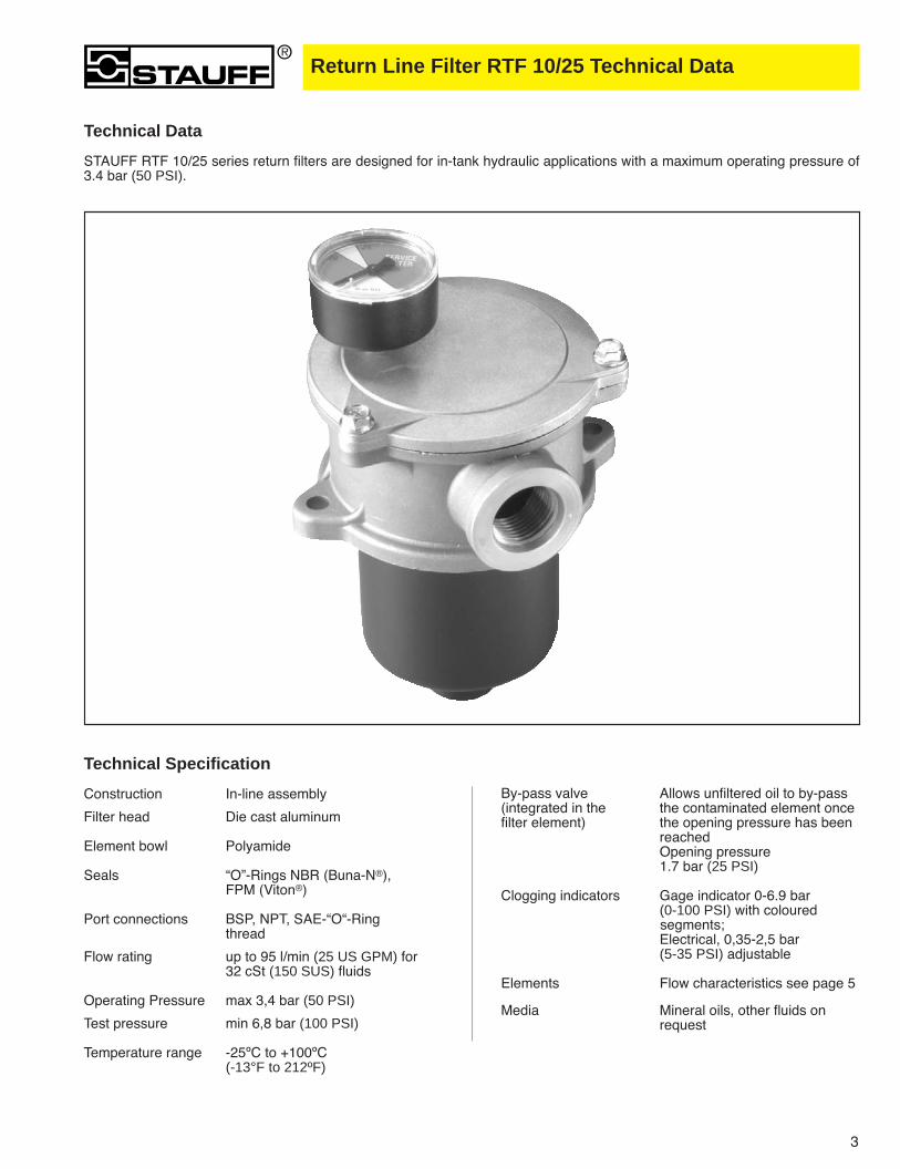
Technical Data
STAUFF RTF 10/25 series return filters are designed for in-tank hydraulic applications with a maximum operating pressure of3.4 bar (50 PSI).
By-pass valve Allows unfiltered oil to by-pass (integrated in the the contaminated element oncefilter element) the opening pressure has been
reached Opening pressure1.7 bar (25 PSI)
Clogging indicators Gage indicator 0-6.9 bar(0-100 PSI) with coloured segments; Electrical, 0,35-2,5 bar (5-35 PSI) adjustable
Elements Flow characteristics see page 5
Media Mineral oils, other fluids on request
Technical Specification
Construction In-line assembly
Filter head Die cast aluminum
Element bowl Polyamide
Seals “O”-Rings NBR (Buna-N®), FPM (Viton®)
Port connections BSP, NPT, SAE-“O“-Ring thread
Flow rating up to 95 l/min (25 US GPM) for 32 cSt (150 SUS) fluids
Operating Pressure max 3,4 bar (50 PSI)
Test pressure min 6,8 bar (100 PSI)
Temperature range -25ºC to +100ºC (-13°F to 212ºF)
3

Dimensions
Thread connection G Weight
Filter SAE-”O” BowlSize BSP NPT Ring length h1 h2 h3 h4 h5 b1 b2 d1 d2 d3 kg lbs
RTF 10 G 1/2 1/2 N/A S1 26 21 87 133 8 50 90 66 24 7 0,45 1(1,02) (0,83) (3,43) (5,24) (0,32) (1,97) (3,54) (2,60) (0,94) (0,28)
RTF 25 G 1 1 15/16-12 UNF S1 34 29 105 170 10 67 115 86 28 9 0,9 2(1,34) (1,14) (4,13) (6,69) (0,39) (2,64) (4,65) (3,39) (1,10) (0,35)
RTF 25 G 1 1 15/16-12 UNF S2 34 29 150 215 10 67 115 86 28 9 1 2,2(1,34) (1,14) (5,91) (8,46) (0,39) (2,64) (4,65) (3,39) (1,10) (0,35)
Dimensions RTF 10/25 Filters All dimensions in mm (inch)
b1
h 1
h 5
h 2h 3
h 4
G
M10x1 or 1/8” NPT port
ød2
b2
ød1
ød3
Return Line Filter RTF 10/25 Dimensions
for filter indicator
4
Seal material
B NBR (Buna®)
Return Line Filters RTF 10/25 Ordering Code & Flow Characteristics
Filter material
Code MaterialD Filter paperG Inorganic glass fiber
RTE 25 D 10 B / S2 /X
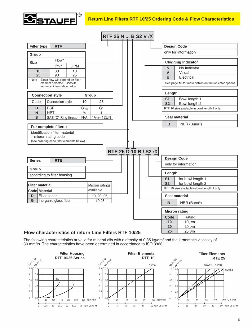
Flow characteristics of return Line Filters RTF 10/25
Series RTE
Group
according to filter housing
Filter type RTF
For complete filters:
identification filter material+ micron rating code(see ordering code filter elements below)
Micron ratingsavailable
10, 20, 25, 10,25
RTF 25 N ... B S2 V /X
Clogging Indicator
N No IndicatorV VisualE Electrical
See page 18 for more details on the indicator options.
Length
S1 Bowl length 1S2 Bowl length 2
* Note Exact flow will depend on filter element selected. Consult technical information below.
RTF 10 size available in bowl length 1 only
Seal material
B NBR (Buna®)
Length
S1 for bowl length 1S2 for bowl length 2
RTF 10 size available in bowl length 1 only
Group
SizeFlow*
l/min GPM10 38 1025 90 25
The following characteristics ar valid for mineral oils with a density of 0,85 kg/dm3 and the kirnematic viscosity of 30 mm2/s. The characteristics have been determined in accordance to ISO 3968.
Connection style Group
Code Connection style 10 25
B BSP G1/2 G1N NPT 1/2 1S SAE “O”-Ring thread N/A 15/16 - 12UN
Filter HousingRTF 10/25 Series
0 12.5 25 37.5 50 62.5 75
7.5
6
4.5
3
1.5
0
0.5
0.4
0.3
0.2
0.1
0.0
∆p in
PSI
∆p in
bar
Q in l/min
Q in US GPM
0 50 100 150 200 250 300
Filter ElementsRTE 10
0 5 10 15 20 25
7.5
6
4.5
3
1.5
0
0.5
0.4
0.3
0.2
0.1
0.0
∆p in
PSI
∆p in
bar
Q in l/min
Q in US GPM
0 20 40 60 80 100
Filter ElementsRTE 25
0 10 20 30 40 50
7.5
6
4.5
3
1.5
0
0.5
0.4
0.3
0.2
0.1
0.0
∆p in
PSI
∆p in
bar
Q in l/min
Q in US GPM
0 40 80 120 160 200
D20S1
1/2”
1”
G10S2 D10S2
D25S2
5
Design Code
only for information
Design Code
only for information
Micron rating
Code Rating10 10 µm20 20 µm25 25 µm

Return Line Filter RTF 40 Series Technical Data
Technical Data
STAUFF RTF 40 series return filters are designed for in-tank hydraulic applications with a maximum operating pressure of 6.9bar (100 PSI). The filter bowl is designed to return the oil beneath the surface thus preventing entrainment of air. The RTF48elements interchange with the popular “K” series and the RTF49 elements interchange with the “RTE-409” series elements.
By-pass valve Allows unfiltered oil to by-pass the contaminated element oncethe opening pressure has beenreached
By-pass setting 1.7 bar (25 PSI)(by-pass in element for RTF47,by-pass in head for RTF48 andRTF49)
Clogging indicators Gage indicator 0-6.9 bar(0-100 PSI) with coloured segments; electrical, 0,35-2,5 bar (5-35 PSI) adjustable
Elements Flow characteristics see page 9
Media Mineral oils, other fluids on request
Technical Specification
Construction Tank top flange mounting
Filter head Die cast aluminum
Element bowl Bowl length 1, PolyamideBowl length 2, Steel
Seals “O”-Rings NBR (Buna-N®),
Port connections BSP, NPT, SAE-“O“-Ring thread, SAE flange
Flow rating up to 379 l/min (100 US GPM) for 32cSt (150 SUS) fluids
Operating Pressure max 6,9 bar (100 PSI)
Temperature range -25ºC to +95ºC (-13°F to 212ºF)
6

Return Line Filter RTF 40 Series Dimensions
Dimensions
Dimensions RTF 40 FiltersAll dimensions in mm (inch)
b3
G
ød1
b5b1
ød4
ød3
ød2
b4
h2
h1h3
h5
h4
d6 b2
h6
Port B
(optional)
M10x1 or 1/8” NPT
port for cloggingindicator (both sides)
Port A
Mounting detail(bottom view)
7
or
d2
Bowl NPT &Length h1 h2 h3 h4 h5 h6 b1 b2 b3 b4 b5 b6 d1 BSP SAE d3 d4 G
S1
53 122
263 385 21
11 152 152 69,85 35,56 112 112 122 M121/2-13 38,1 11
G1-1/2”(10,35) (15,16) (0,83)
S2
(2,09) (4,80)
475 597 38
(0,43) (5,98) (5,98) (2,75) (1,40) (4,41) (4,41) (4,80) UN 2B (1,50) (0,43)
(18,70) (23,50) (1,50)
1-1/2NPT

Return Line Filter RTF 40 Series Ordering Code
Filter material
Code MaterialD Filter paperG Inorganic glass fiber
RTF 48 D 10 B /X
Group
according to filter housing
Filter type RTF47 RTF48 RTF49
For complete filters:
identification filter material+ micron rating code(see ordering code filter elements below)
Seal material
B NBR (Buna®)other seal material on request
By-pass valve
Code NBR (Buna®)
00 No by-pass
15 1 bar (15 PSI)25 1,7 bar (24,6 PSI)
Micron ratingCode Rating03 03 µm10 10 µm20 20 µm25 25 µm
Micron ratingsavailable
03, 10, 20, 2503,10, 25
RTF 48 N 25 ... B / S2 / V /X
Clogging indicatorN NoneV VisualE Electrical
See page 18 for more details on the indicator options.
Length
S1 for bowl length 1 (1 element)S2 for bowl length 2 (2 elements)
Note: RTF 47 available in S1 bowl only
Seal material
B NBR (Buna®)other seal material on request
8
Design Code
only for information
Design Code
only for information
Connection style Group
Code Connection style Port A Port B
B BSP G1-1/4 & 1-1/2 SAE flange NoneBB BSP G1-1/4 & 1-1/2 SAE flange G1-1/4N NPT 1-1/4 NPT & 1-1/2 SAE flange None
NN NPT 1-1/4 NPT & 1-1/2 SAE flange 1-1/4 NPTM NPT 1-1/2 NPT None
MN NPT 1-1/2 NPT 1-1/2 NPTMM NPT 1-1/2 NPT 1-1/2NPTS SAE 1-5/8 -12 UN None
SS SAE 1-5/8 -12 UN 1-5/8 -12 UNST SAE 1-5/8 -12 UN 1-7/8 -12 UNSU SAE 1-5/8 -12 UN 2-1/2 -12 UNSO Combination 1-5/8 -12 UN 2 NPT
Return Line Filter RTF 40 Series Flow Characteristics
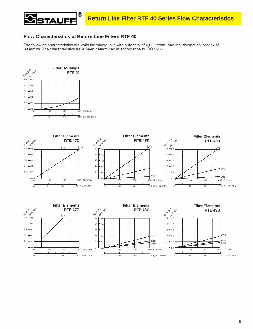
Flow Characteristics of Return Line Filters RTF 40
The following characteristics are valid for mineral oils with a density of 0,85 kg/dm3 and the kinematic viscosity of 30 mm2/s. The characteristics have been determined in accordance to ISO 3968.
Filter HousingsRTF 40
0 40 80 120
7.5
6
4.5
3
1.5
0
0.5
0.4
0.3
0.2
0.1
0.0
∆p in
PSI
∆p in
bar
Q in l/min
Q in US GPM
0 150 300 450
Filter ElementsRTE 47D
0 25 50 75
7.5
6
4.5
3
1.5
0
0.5
0.4
0.3
0.2
0.1
0.0
∆p in
PSI
∆p in
bar
Q in l/min
Q in US GPM
0 100 200 300
D10G10
Filter ElementsRTE 47G
0 25 50 75
7.5
6
4.5
3
1.5
0
0.5
0.4
0.3
0.2
0.1
0.0
∆p in
PSI
∆p in
bar
Q in l/min
Q in US GPM
0 100 200 300
G10
Filter ElementsRTE 49D
0 40 80 120
30
24
18
12
6
0
2.0
1.6
1.2
0.8
0.4
0.0
30
24
18
12
6
0
2.0
1.6
1.2
0.8
0.4
0.0
∆p in
PSI
∆p in
bar
Q in l/min
Q in US GPM
0 150 300 450
Filter ElementsRTE 48D
0 40 80 120
∆p in
PSI
∆p in
bar
Q in l/min
Q in US GPM
0 150 300 450
Filter ElementsRTE 49G
0 40 80 120
30
24
18
12
6
0
2.0
1.6
1.2
0.8
0.4
0.0
30
24
18
12
6
0
2.0
1.6
1.2
0.8
0.4
0.0
∆p in
PSI
∆p in
bar
Q in l/min
Q in US GPM
0 150 .300 450
Filter ElementsRTE 48G
0 40 80 120
∆p in
PSI
∆p in
bar
Q in l/min
Q in US GPM
0 150 300 450
D03 D03
D10
D25
D10
D25
G03
G10G20
G03
G10G20
9

Return Line Filter RTF20 Technical Data
Technical Data
STAUFF RTF20 series return filters are designed for in-tank hydraulic applications with a maximum operating pressure of10 bar (145 PSI) and flows up to 110 l/min (30 US GPM). The filter bowl is designed to return the oil beneath the surfacethus preventing entrainment of air. RTF20 series compact design and integral breather make them ideal for mobile hy-draulic applications.
Technical Specification
Construction Tank top flange mounting
Filter head Die cast aluminium
Element bowl Polyamide and screw cap
Seals “O”-Rings NBR (Buna-N®) FPM (Viton®)
Port connections BSP, NPT, SAE “O”-Ring thread
Flow rating up to 115 l/min (30 US GPM) for 32 cSt (150 SUS) fluids
Operating pressure max 10 bar (145 PSI)
Test pressure min 24 bar (350 PSI)
Temperature range -25°C to +100°C (-13°F to 212°F)
Integrated Breather 10 or 40 µm paper media
By-pass valve Allows unfiltered oil to by-pass(integrated in the the contaminated element filter element) once the opening pressure has
been reachedOpening pressure1.7 bar (25 PSI)
Clogging indicators Gage indicator 0-6.9 bar (0-100 PSI) with coloured segmentsElectrical, 0.35 - 2.5 bar (5-35 PSI) adjustable
Filter elements Flow characteristics see page 13
Media Mineral oils, other fluids on request
10

Dimensions41 (1
,61)
24
(0,9
4)
202
(7,9
5)
2
(0,0
7)
77
(3,0
3)
11 (0,4
3)
16
(0,6
3)
178
(7,0
1)ø75
(2,95)
50
(1,97)
88
(3,23)
(3,46)
8270
(2,76)
ø61,5 ± 1,5
(2,42 ± 0.06)
ø28
(1,1)
1/2” or 3/4” BSP, NPT
or SAE port
Return Line Filter RTF20 Dimensions
Dimensions in mm (inch)
11
Mounting detail(bottom view)
M10x1 or 1/8” NPTport for cloggingindicator (both sides)

Return Line Filter RTF20 Ordering Code
Filter type RTF20
Series RTE20
RTF 20 N1 ... B V B10 D /X
Clogging indicator
N without clogging indic.V visualE electrical
See page 18 for more details on the indicatoroptions.
Ordering Code Filter Housings
Ordering Code Filter Elements
For complete filters:
identification filter material+ micron rating code(see ordering code filter elements below)
Seal materialB NBR (Buna®)
RTE20 D 10 B /X
Micron rating06 6 µm10 10 µm20 20 µm
Seal materialB NBR (Buna®)
Micron ratingsavailable
BreatherB10 10 µm paper
B40 40 µm paper
Dipstick- Without dipstick
D Dipstick
Connection StyleCode Connection StyleB1 BSP G 1/2B2 BSP G 3/4N1 NPT 1/2N2 NPT 3/4S1 SAE- “O”- Ring Thread 3/4 -16 UNS2 SAE- “O”- Ring Thread 1 1/16 -12 UN
12
Design Code
only for information
Design Code
only for information
Filter materialCode Material
D Filterpaper 10G Inorganic glass fiber 6,10,20

Return Line Filter RTF20 Flow Characteristics
Flow Characteristics
The following characteristics are valid for mineral based fluids with a density of 0,85 kg/dm3 and the kinematic viscosityof 30 mm2/s. The characteristics have been determined in accordance to ISO 3968.
Filter HousingRTF 20
0 12.5 25 37.5
7.5
6
4.5
3
1.5
0
0.5
0.4
0.3
0.2
0.1
0.0
∆p in
PSI
∆p in
bar
Q in l/min
Q in US GPM
0 50 100 150
Filter ElementsRTE 20
0 10 20 30
7.5
6
4.5
3
1.5
0
0.5
0.4
0.3
0.2
0.1
0.0
∆p in
PSI
∆p in
bar
Q in l/min
Q in US GPM
0 40 80 120
Filter BreatherRTF 20
0 10 20 30 40 50 60
7.5
6
4.5
3
1.5
0
0.5
0.4
0.3
0.2
0.1
0.0
∆p in
PSI
∆p in
bar
Q in l/min
Q in US GPM
0 40 80 120 160 200 240
D10
G20G10G06
1/2” 3/4”
B10
B40
13

Return Line Filter RTF30 Technical Data
Technical Data
STAUFF RTF30 series return filters are designed for in-tank hydraulic applications with a maximum operating pressure of 10bar (145 PSI) and flows up to 152 l/min (40 US GPM). The filter bowl is designed to return the oil beneath the surface thus pre-venting entrainment of air. RTF30 series compact design and integral breather makes them ideal for mobile hydraulic applica-tions.
Technical Specification
Construction Tank top flange mounting
Filter head Die cast aluminium
Element bowl Polyamide and screw cap
Seals “O”-Rings NBR (Buna-N®) FPM (Viton®)
Port connections BSP, NPT, SAE “O”-Ring thread
Flow rating up to 152 l/min (40 US GPM) for 32 cSt (150 SUS) fluids
Operating pressure max 10 bar (145 PSI)
Test pressure min 24 bar (350 PSI)
Temperature range -25°C to +100°C (-13°F to 212°F)
Integrated Breather 10 or 40 µm paper media
By-pass valve Allows unfiltered oil to by-pass(integrated in the the contaminated element filter element) once the opening pressure has
been reachedOpening pressure1.7 bar (25 PSI)
Clogging indicators Gage indicator 0-6.9 bar (0-100 PSI) with coloured segments;Electrical, 0.35 - 2.5 bar (5-35 PSI) adjustable
Filter elements Flow characteristics see page 17
Media Mineral oils, other fluids on request
14

140 110(5,51) (4,33)
min 87 min 8760 205 175 30 22 1,5 104 36 max 91 70 83 110 115 11 max 91 103
(2,36) (8,07) (6,89) (1,18) (0,87) (0,06) (4,09) (1,42) (min 3,43) (2,76) (3,27) (4,33) (4,53) (0,43) (min 3,43) (4,06)(max 3,58) (max 3,58)
305 275(12,01) (10,83)
Dimensions
h 1
h 4
h 6
h 2
h 3
h 5 ød2
b3
b2b1 b4
ød3
ød1
or SAE ports
3/4” or 1” BSP, NPT
FilterSize
RTF30
RTF31
RTF32
h1 h2 h3 h4 h5 h6 d1 d2 d3 b1 b2 b3 b4 b5 b6 b7
Dimensions
Return Line Filter RTF30 Dimensions
Dimensions in mm (inch)
b 7 b 6 b 5
15
M10x1 or 1/8” NPTport for cloggingindicator (both sides)
Mounting detail(bottom view)

Return Line Filter RTF30 Ordering Code
RTF 31 N1 ... B V B10 D /X
Dipstick- Without dipstick
D Dipstick
Clogging indicatorN without clogging indic.V visualE electrical
See page 18 for more details on the indicator options.
Ordering Code Filter Housings
Ordering Code Filter Elements
For complete filters:
identification filter material+ micron rating code(see ordering code filter elements below)
RTE31 D 10 B /X
Micron rating06 6 µm10 10 µm20 20 µm
Seal material
B NBR (Buna®)Micron ratingsavailable
Filter Type
RTF30 110mm (4,33 in) bowl length
RTF31 175mm (6,89 in) bowl length
RTF32 275mm (10,83 in) bowl length
Connection StyleCode Connection StyleB1 BSP 3/4”B2 BSP 1”N1 NPT 3/4”N2 NPT 1”S1 SAE O-Ring Thread 1-1/16 -12 UNS2 SAE O-Ring Thread 1-5/16 -12 UN
BreatherB10 10 µm paper
B40 40 µm paper
Seal material
B NBR (Buna®)
Series RTE
Groupaccording to filter housing
Filter materialCode Material
D Filterpaper 10G Inorganic glass fiber 6,10,20
16
Design Code
only for information
Design Code
only for information

Return Line Filter RTF30 Flow Characteristics
Flow Characteristics
The following characteristics are valid for mineral based fluids with a density of 0,85 kg/dm3 and the kinematic viscosityof 30 mm2/s. The characteristics have been determined in accordance to ISO 3968.
Filter HousingsRTF 30/31/32
0 12.5 25 37.5
7.5
6
4.5
3
1.5
0
0.5
0.4
0.3
0.2
0.1
0.0
∆p in
PSI
∆p in
bar
Q in l/min
Q in US GPM
0 50 100 150
Filter ElementsRTE 30
0 12.5 25 37.5
15
12
9
6
3
0
1.0
0.8
0.6
0.4
0.2
0.0
∆p in
PSI
∆p in
bar
Q in l/min
Q in US GPM
0 50 100 150
G06 G10
D10
1”
3/4”
G20
Filter ElementsRTE 32
0 12.5 25 37.5
15
12
9
6
3
0
1.0
0.8
0.6
0.4
0.2
0.0
∆p in
PSI
∆p in
bar
Q in l/min
Q in US GPM
0 50 100 150
D10
G10
G06
G20
Filter BreatherRTF 30/31/32
0 20 40 60
15
12
9
6
3
0
0.1
0.08
0.06
0.04
0.02
0.00
∆p in
PSI
∆p in
bar
Q in l/min
Q in US GPM
0 80 160 240
B40
B10
Filter ElementsRTE 31
0 12.5 25 37.5
15
12
9
6
3
0
1.0
0.8
0.6
0.4
0.2
0.0
∆p in
PSI
∆p in
bar
Q in l/min
Q in US GPM
0 50 100 150
G06 G10
D10
G20
17
Filter Indicators
18
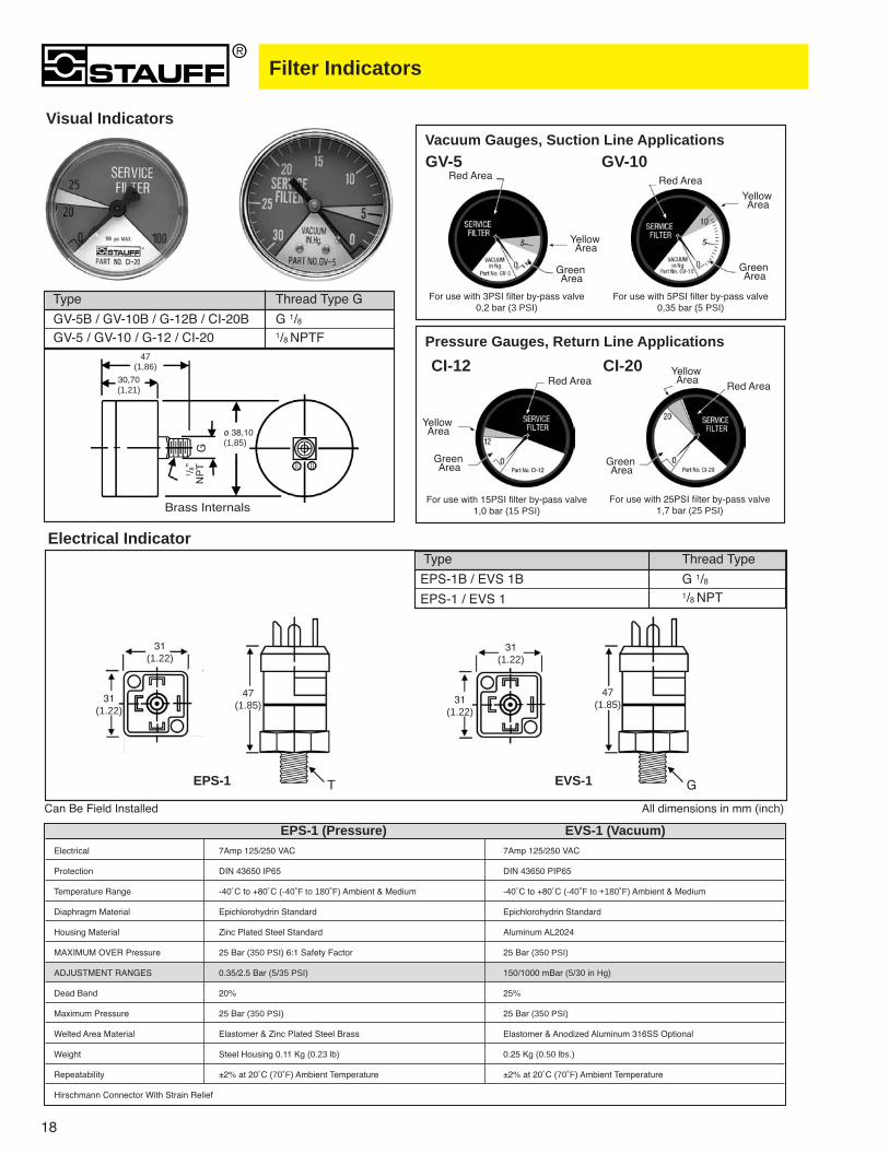
EPS-1 (Pressure) EVS-1 (Vacuum)Electrical 7Amp 125/250 VAC 7Amp 125/250 VAC
Protection DIN 43650 IP65 DIN 43650 PIP65
Temperature Range -40˚C to +80˚C (-40˚F to 180˚F) Ambient & Medium -40˚C to +80˚C (-40˚F to +180˚F) Ambient & Medium
Diaphragm Material Epichlorohydrin Standard Epichlorohydrin Standard
Housing Material Zinc Plated Steel Standard Aluminum AL2024
MAXIMUM OVER Pressure 25 Bar (350 PSI) 6:1 Safety Factor 25 Bar (350 PSI)
ADJUSTMENT RANGES 0.35/2.5 Bar (5/35 PSI) 150/1000 mBar (5/30 in Hg)
Dead Band 20% 25%
Maximum Pressure 25 Bar (350 PSI) 25 Bar (350 PSI)
Welted Area Material Elastomer & Zinc Plated Steel Brass Elastomer & Anodized Aluminum 316SS Optional
Weight Steel Housing 0.11 Kg (0.23 lb) 0.25 Kg (0.50 lbs.)
Repeatability ±2% at 20˚C (70˚F) Ambient Temperature ±2% at 20˚C (70˚F) Ambient Temperature
Hirschmann Connector With Strain Relief
Can Be Field Installed
EPS-1
Vacuum Gauges, Suction Line Applications
Pressure Gauges, Return Line Applications
GV-5 GV-10
CI-12 CI-20
Red Area Red Area
Red AreaRed Area
YellowArea
YellowArea
YellowArea
YellowArea
GreenArea
GreenArea
GreenArea
GreenArea
For use with 3PSI filter by-pass valve0,2 bar (3 PSI)
For use with 5PSI filter by-pass valve0,35 bar (5 PSI)
For use with 15PSI filter by-pass valve1,0 bar (15 PSI)
For use with 25PSI filter by-pass valve1,7 bar (25 PSI)
Electrical Indicator
Visual Indicators
31(1.22)
31(1.22)
47(1.85)
1 /8”
NP
TG
47(1,86)
30,70(1,21)
T GEVS-1
31(1.22)
31(1.22)
47(1.85)
All dimensions in mm (inch)
Type Thread Type G
GV-5B / GV-10B / G-12B / CI-20B G 1/8GV-5 / GV-10 / G-12 / CI-20 1/8 NPTF
Type Thread Type
EPS-1B / EVS 1B G 1/8
EPS-1 / EVS 1 1/8 NPT
Brass Internals
ø 38,10(1,85)


![[MS-OXRTFCP]: Rich Text Format (RTF) Compression Algorithm · The Rich Text Format (RTF) Compression Algorithm is used to compress and decompress RTF data, as described in [MSFT-RTF],](https://img.pdfslide.us/doc/110x75/5e9e1be31138b067ae753825/ms-oxrtfcp-rich-text-format-rtf-compression-algorithm-the-rich-text-format.jpg)