Embed Size (px)
Citation preview

www.rosemount-tg.com
Technical Description703010En, Ed. 5, Rev BNovember 2012
High Precision Tank Gauging System
TankRadar RexTechnical Description
703010En, Ed. 5, Rev BNovember 2012
2
ContentsAvailable technical documentation for TankRadar Rex: ________________________________________________________4Abbreviations used in this document: _______________________________________5
TankRadar Rex – the industry standard tank gauging system _______________________________6Applications ____________________________________________________________6Summary of functions & system overview ____________________________________7Installation and commissioning of the TankRadar Rex System ____________________8
Radar level gauging ____________________________________________________9The FMCW method ______________________________________________________9Accuracy enhancement _________________________________________________10
Temperature control _________________________________________________10Digital reference ____________________________________________________10Drip-off means no condensation ________________________________________10Measurement close to tank wall ________________________________________10Patented method for detecting the surface echo ___________________________ 11
No risk to be exposed to the microwaves from the TankRadar Rex antenna _________ 11Lightning Protection ____________________________________________________ 11SIL 2 Safety Functions __________________________________________________ 11Reach more tanks at less cost with Smart Wireless solution _____________________ 11
Better Utilization of Tank Capacity ______________________________________12Intelligent Self-organizing Mesh Network Increases Reliability ________________12Smart Wireless for More Secure Data Transmission ________________________12Wireless Connection of Tank Gauging Equipment __________________________12
Radar Tank Gauges ___________________________________________________13Transmitter Head ______________________________________________________13
Transmitter Head Electronics __________________________________________13Metrological Seal (option) _____________________________________________14Cable Connections to the Transmitter Head _______________________________16
Horn Antenna Gauge RTG 3920 __________________________________________18Parabolic Antenna Gauge RTG 3930 _______________________________________19Still-Pipe Array Antenna Gauge RTG 3950 ___________________________________20LPG/LNG Gauge RTG 3960 ______________________________________________21
Temperature measurement _____________________________________________23
Water interface measurement ___________________________________________26
Data Acquisition Unit, DAU 2100 _________________________________________27Local Read-out ________________________________________________________27
Remote Display Unit, RDU 40 ___________________________________________28
Field Communication Unit, FCU 2160 _____________________________________29
Field Bus Modem, FBM 2180 ____________________________________________33
Technical Description703010En, Ed. 5, Rev BNovember 2012 TankRadar Rex
3
Junction Boxes _______________________________________________________34JB 140-11 and JB 140-15 for EEx i and EEx e environments _____________________34JB 36 and JB42 for connection of temperature sensors _________________________34Junction Box Integrated with Temperature Sensor or Water Level Sensor ___________34Junction Boxes with Conduit Outlets _______________________________________34
TankMaster HMI software _______________________________________________35
TankMaster I/O Terminals _______________________________________________39
Tank inventory and density through hybrid calculations in the Rex system _____40
TankRadar Rex System Configurations ___________________________________41The TRL2 Bus - A fast and reliable data bus ____________________________________41Stand-Alone Application _________________________________________________42Systems with a TankMaster Work Station ____________________________________42Connecting the Field Communication Unit FCU 2160 __________________________42Redundancy __________________________________________________________43Wireless Mesh Network Always Finds a Way to Communicate ___________________44Example of a General System ____________________________________________45
Connection to other systems ___________________________________________46
Emulation ____________________________________________________________47Gauge Emulation ______________________________________________________47Seamless control room connectivity ________________________________________47
Certificates __________________________________________________________48Accuracy approvals / Legal metrological certificates ___________________________48EX Approvals _________________________________________________________48Safety Approvals and Acknowledgements ___________________________________48Emission Approvals _____________________________________________________48Miscellaneous Approvals ________________________________________________49Vapor Influence on Radar Measurement ____________________________________49
Ordering information __________________________________________________50Radar Tank Gauge (RTG 3900) ___________________________________________50Data Acquisition Unit (DAU 2100) __________________________________________55 Remote Display Unit (RDU 40) ____________________________________________55Junction Box and Protective Hose Kit _______________________________________55Field Communication Unit (FCU 2160) ______________________________________56Field Bus Modems _____________________________________________________57TankMaster™ Software _____________________________________________________________58Temperature and Water Level Sensors for the US and Canada ___________________63Pressure Transmitters ___________________________________________________66Wireless _____________________________________________________________68
TankRadar RexTechnical Description
703010En, Ed. 5, Rev BNovember 2012
4
Copyright © November 2012 by Rosemount Tank Radar AB, Sweden. Ref. no. 703010En. Ed 5, Rev B
Technical data is subject to change without prior notice. Rosemount Tank Radar AB accepts no responsibility for any errors that may appear in this description.
Allen-Bradley, Bailey, DEC, Enraf, Fisher, Foxboro, GPE, Honeywell, IBM, L&J, Profibus, Rosemount, TankRadar, Siemens, Tiway, Varec, Vega, Whessoe, and Yokogawa are registered trademarks and trademarks of these organizations and companies.
Viton is a registered trademark of Du Pont Performance Elastomers.
Available technical documentation for TankRadar Rex:
• Technical Description
• Installation Manual
• TankMaster WinSetup User’s Guide
• TankMaster WinOpi User’s Guide
• Commissioning Manual & Checklist
• Installation Drawings
• Service Manual
The Technical Description includes technical data on the various parts of the TankRadar Rex system.
The Installation Manual is used for planning and performing the installation.
The Commissioning Manual & Commissioning Checklist include information on how to commission the TankRadar Rex System. They are used together with the TankMaster WinSetup User’s Guide.
The TankMaster WinSetup User’s Guide describes how to start-up the system using the WinSetup software on a personal computer. TankMaster is the Human Machine Interface (HMI) software for TankRadar Rex. It includes the WinSetup and WinOpi software modules.
The TankMaster WinOpi User’s Guide describes the inventory and display functions included in the optional TankMaster WinOpi software.
The Service Manual is used for service and trouble shooting.
Technical Description703010En, Ed. 5, Rev BNovember 2012 TankRadar Rex
5
Abbreviations used in this document:
APC Analog Processing CardAPI American Petroleum InstituteDAU Data Acquisition UnitDCS Digital Control System. EEPROM Electrically Erasable Programmable Read Only MemoryFBM Field Bus ModemFCC Field Communication CardFCU Field Communication UnitFMCW Frequency Modulated Continuous WaveFSK Frequency Shift KeyedHMI Human Machine InterfaceIS Intrinsically SafeISO International Standard OrganizationJB Junction BoxLCD Liquid Crystal DisplayOIML International Organization of Legal Metrology PC Personal ComputerPCB Printed Circuit BoardPROM Programmable Read Only MemoryPTB Physikalisch Technische BundesanstaltPTFE Polytetrafluoroethylene. RDU Remote Display UnitRF-head A device for emitting and receiving microwaves.ROC Relay Output CardRTD Resistance Temperature DetectorsRTG Radar Tank GaugeSCADA Supervisory Control and Data Acquisition SystemSPC Signal Processing CardTH Transmitter HeadTHE Transmitter Head ElectronicsTIC Transmitter Interface CardTM TankMasterTMC Transmitter Multiplexer CardTRC Transformer Rectifier CardTRL TankRadar L (First generation)TÜV Technischer Übervachungs-Verein VAC Volts Alternating CurrentVDC Volts Direct Current
TankRadar RexTechnical Description
703010En, Ed. 5, Rev BNovember 2012
6
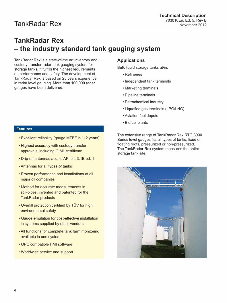
TankRadar Rex – the industry standard tank gauging systemTankRadar Rex is a state-of-the art inventory and custody transfer radar tank gauging system for storage tanks. It fulfills the highest requirements on performance and safety. The development of TankRadar Rex is based on 25 years experience in radar level gauging. More than 100 000 radar gauges have been delivered.
Features
• Excellent reliability (gauge MTBF is 112 years)
• Highest accuracy with custody transfer approvals, including OIML certificate
• Drip-off antennas acc. to API ch. 3.1B ed. 1
• Antennas for all types of tanks
• Proven performance and installations at all major oil companies
• Method for accurate measurements in still-pipes, invented and patented for the TankRadar products
• Overfill protection certified by TÜV for high environmental safety
• Gauge emulation for cost-effective installation in systems supplied by other vendors
• All functions for complete tank farm monitoring available in one system
• OPC compatible HMI software
• Worldwide service and support
ApplicationsBulk liquid storage tanks at/in:
• Refineries
• Independent tank terminals
• Marketing terminals
• Pipeline terminals
• Petrochemical industry
• Liquefied gas terminals (LPG/LNG)
• Aviation fuel depots
• Biofuel plants
The extensive range of TankRadar Rex RTG 3900 Series level gauges fits all types of tanks, fixed or floating roofs, pressurized or non-pressurized. The TankRadar Rex system measures the entire storage tank site.
Technical Description703010En, Ed. 5, Rev BNovember 2012 TankRadar Rex
Rosemount TankRadar
FBM 2180
Ext
. pw
r
RS
-232
US
B
Tx Rx
Lo - GAIN - Hi On - TERM - Off
Profibus® DP
Rex RTG 3960 LPG & LNG
Gauge
Rex RTG 3920 Horn Antenna
Gauge
Rex RTG 3950 Still-Pipe Array Antenna Gauge
Rex RTG 3930 Parabolic Antenna
Gauge
Pro Platinum Cone Antenna
Gauge
Field Communication Unit
Field Bus
Modem
TankMaster PC workstation in
network
Pressure Transmitter
Temperature Sensor
Water Level Sensor
Remote Display Unit
Data Acquisition Unit
Alternative Connections to DCS
Pro Platinum Parabolic Antenna
Gauge
Pro Platinum Still-Pipe Antenna
Gauge
Rosemount 5400
Series
Rosemount 3300
Series
OPC/Network
TankMaster.net PC
www
Customer PC
Communication Supported
• Standard TRL2 Field Bus (Modbus RTU)• Emulation of other vendor’s field buses
Smart Wireless THUM™ Adapter
Smart Wireless Gateway
7
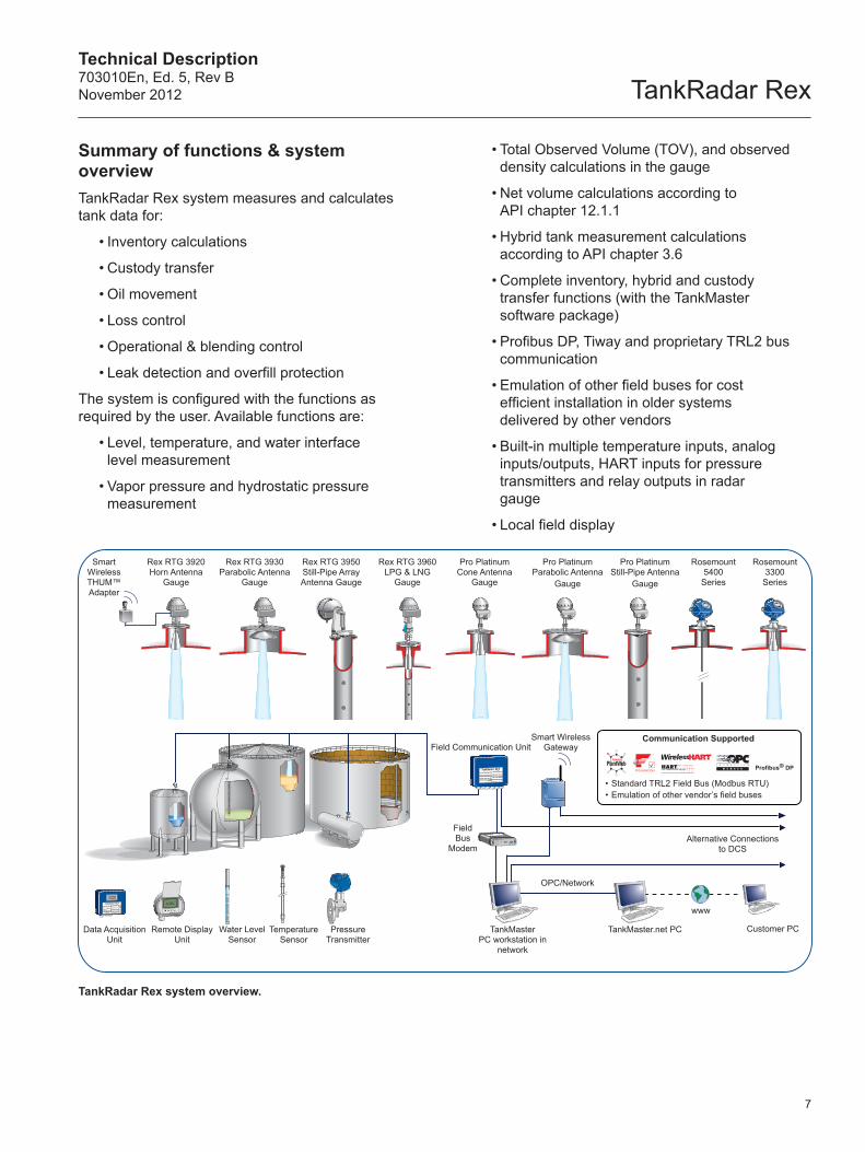
Summary of functions & system overviewTankRadar Rex system measures and calculates tank data for:
• Inventory calculations
• Custody transfer
• Oil movement
• Loss control
• Operational & blending control
• Leak detection and overfill protection
The system is configured with the functions as required by the user. Available functions are:
• Level, temperature, and water interface level measurement
• Vapor pressure and hydrostatic pressure measurement
• Total Observed Volume (TOV), and observed density calculations in the gauge
• Net volume calculations according to API chapter 12.1.1
• Hybrid tank measurement calculations according to API chapter 3.6
• Complete inventory, hybrid and custody transfer functions (with the TankMaster software package)
• Profibus DP, Tiway and proprietary TRL2 bus communication
• Emulation of other field buses for cost efficient installation in older systems delivered by other vendors
• Built-in multiple temperature inputs, analog inputs/outputs, HART inputs for pressure transmitters and relay outputs in radar gauge
• Local field display
TankRadar Rex system overview.
TankRadar RexTechnical Description
703010En, Ed. 5, Rev BNovember 2012
8
Measured values are communicated on a field bus or directly to a PC. In larger systems there are Field Communication Units (FCU:s) that collect data from separate field buses. In this way both stand- alone gauges and large systems with several hundred gauges are economical and have an excellent performance.
The TankRadar Rex system is configured and operated using the OPC compatible TankMaster software package. Its a user-friendly Human Machine Interface (HMI) software that gives the operator a good overview and quick access to any measured values. The software also provides a wide range of inventory and custody transfer functions such as net standard volumes according to API standards, reporting, alarms, graphics, trends etc.
A whole range of plant host computer systems, DCS or SCADA systems can be connected to the TankRadar Rex system for display of measured and calculated values. Protocols for communication with major suppliers of plant host computers have been developed and certified. TankMaster Rex gauges can also be incorporated in other tank gauging manufacturers’ systems using the emulation features.
The TankRadar Rex System can include various integrated equipment, such as:
• Multiple spot temperature sensors
• Water Interface measurement sensors integrated with temperature sensors
• Vapor pressure transmitters
• Hydrostatic pressure transmitters
• TankMaster PC workstations in network
• Local data display on the Data Acquisition Units or on the Remote Display Units
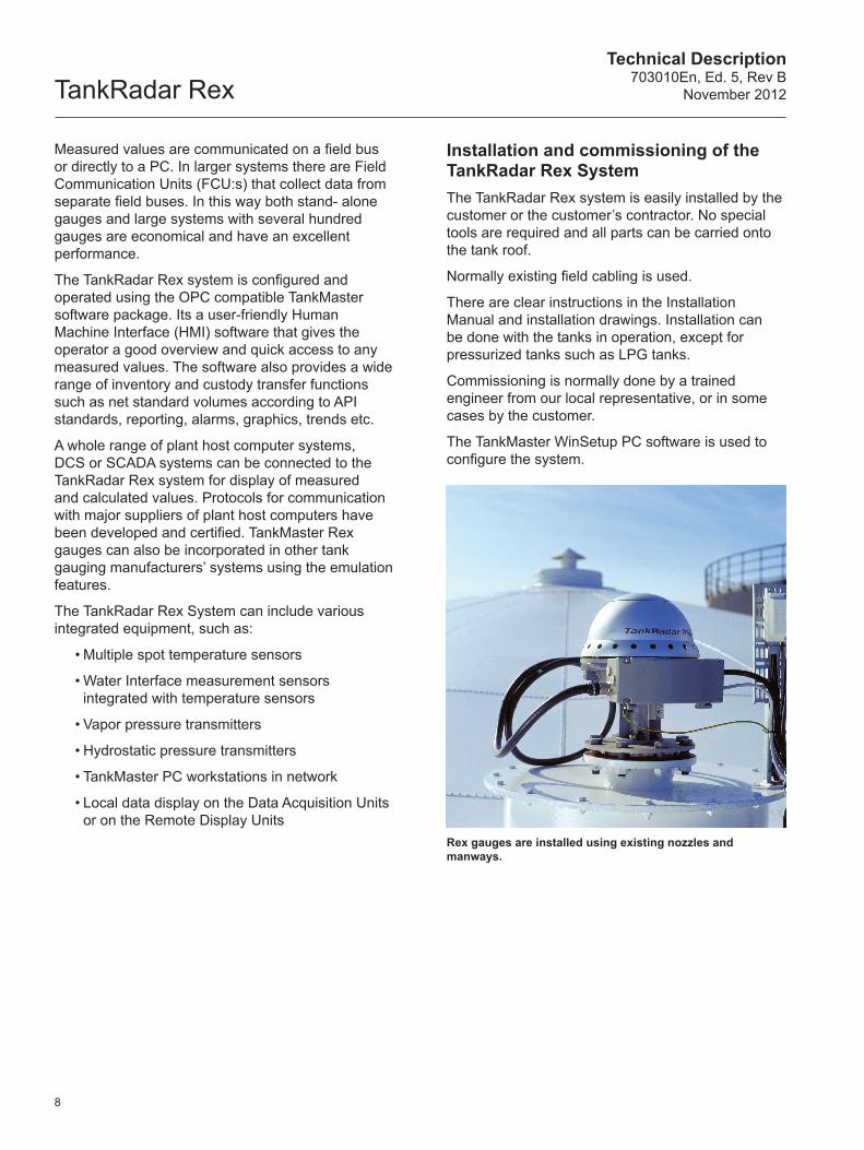
Installation and commissioning of the TankRadar Rex SystemThe TankRadar Rex system is easily installed by the customer or the customer’s contractor. No special tools are required and all parts can be carried onto the tank roof.
Normally existing field cabling is used.
There are clear instructions in the Installation Manual and installation drawings. Installation can be done with the tanks in operation, except for pressurized tanks such as LPG tanks.
Commissioning is normally done by a trained engineer from our local representative, or in some cases by the customer.
The TankMaster WinSetup PC software is used to configure the system.
Rex gauges are installed using existing nozzles and manways.
Technical Description703010En, Ed. 5, Rev BNovember 2012 TankRadar Rex
W11W12FOR INTRINSICALLYSAFE CIRCUITSONLY
"i"
Frequency, f, (GHz)
Time, t
f0f1
f0
f1f
t0 f d
d
9
Radar level gaugingTankRadar Rex gauges provide outstanding reliability using non-contact radar measurement with no moving parts and only the antenna inside the tank atmosphere.
For radar level measurement, there are mainly two modulation techniques:
• Pulse method. Measures the time it takes for a pulse to travel to the surface and back. Pulse radar level gauges are mainly available or lower accuracy applications
• Frequency Modulated Continuous Wave, FMCW. This method is used by high performance radar level gauges
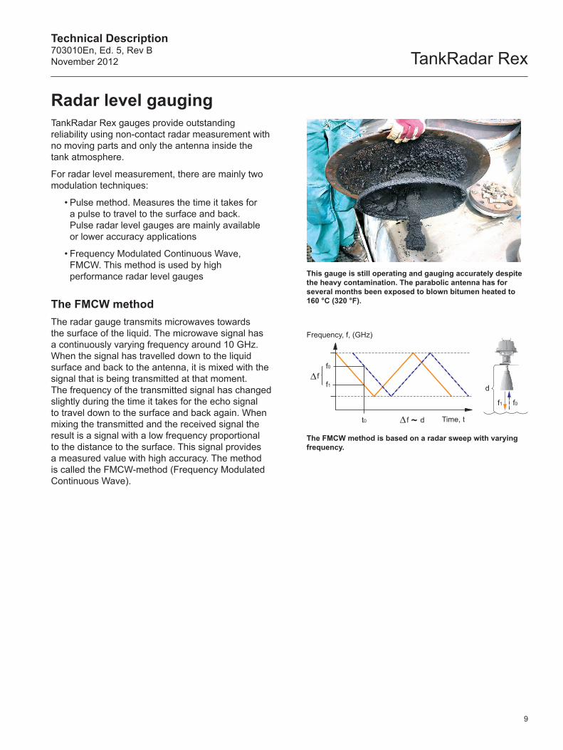
The FMCW methodThe radar gauge transmits microwaves towards the surface of the liquid. The microwave signal has a continuously varying frequency around 10 GHz. When the signal has travelled down to the liquid surface and back to the antenna, it is mixed with the signal that is being transmitted at that moment. The frequency of the transmitted signal has changed slightly during the time it takes for the echo signal to travel down to the surface and back again. When mixing the transmitted and the received signal the result is a signal with a low frequency proportional to the distance to the surface. This signal provides a measured value with high accuracy. The method is called the FMCW-method (Frequency Modulated Continuous Wave).
This gauge is still operating and gauging accurately despite the heavy contamination. The parabolic antenna has for several months been exposed to blown bitumen heated to 160 °C (320 °F).
The FMCW method is based on a radar sweep with varying frequency.
TankRadar RexTechnical Description
703010En, Ed. 5, Rev BNovember 2012
Tank wall
Not accepted
Accepted
Tank Wall
Tank Wall
Liquid Liquid
10
Accuracy enhancementTo enhance accuracy further, TankRadar Rex has some built-in unique features:
Temperature controlTankRadar Rex gauges are designed to operate in all climates. The gauge is continuously controlling the temperature of the electronics and keeps it constant. This is one of the reasons for the 65 years of mean time between failure (MTBF) for the gauge.
Digital referenceA radar gauge needs an internal reference to make the radar sweep absolutely linear. Each deviation from the linearity produces a corresponding inaccuracy. To achieve highest precision, TankRadar Rex uses a digital crystal oscillator. This gives the most stable reference that is available with today’s technology.
Drip-off means no condensationIf the antenna has an inclined polished PTFE-surface where the microwaves are emitted, it will be less susceptible to condensed water or product. The drops of condensation will not coat the active part of the antenna. In this way the radar signal will be less weakened resulting in higher accuracy and better reliability.
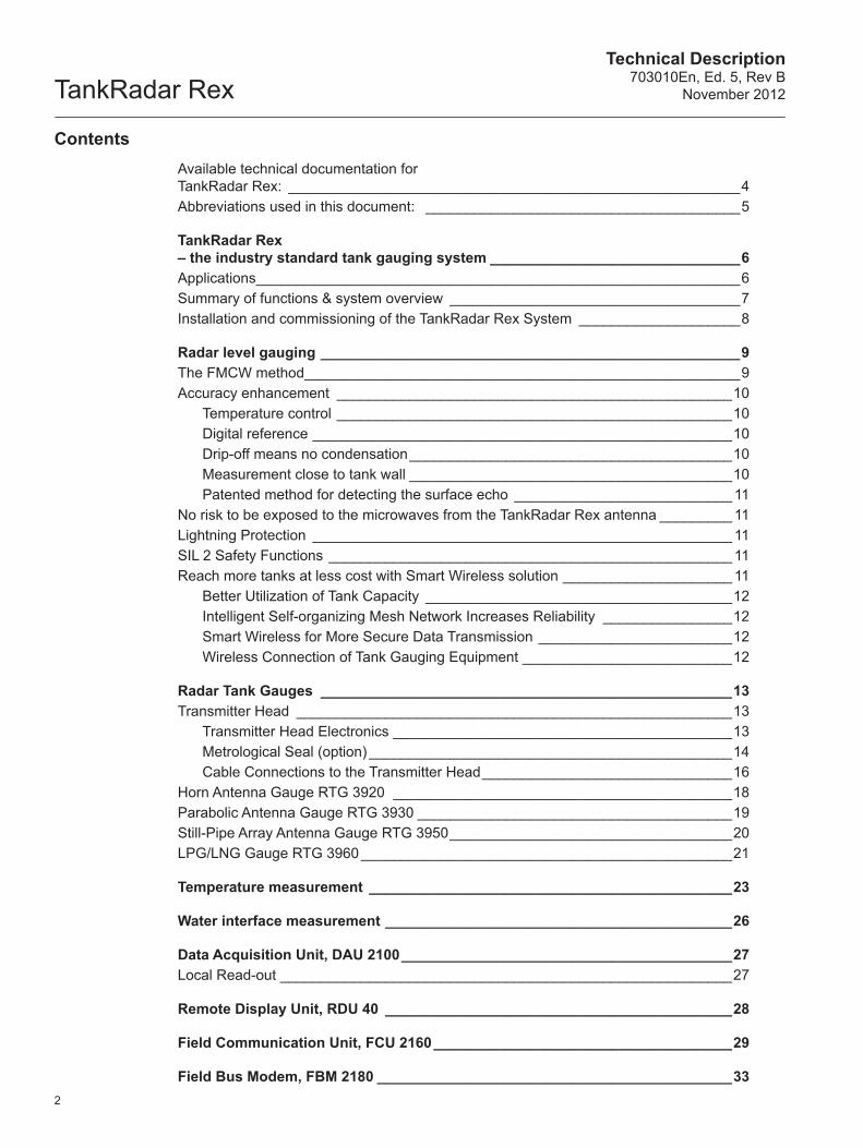
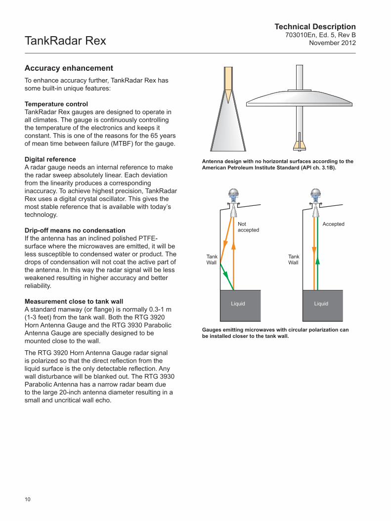
Measurement close to tank wallA standard manway (or flange) is normally 0.3-1 m (1-3 feet) from the tank wall. Both the RTG 3920 Horn Antenna Gauge and the RTG 3930 Parabolic Antenna Gauge are specially designed to be mounted close to the wall.
The RTG 3920 Horn Antenna Gauge radar signal is polarized so that the direct reflection from the liquid surface is the only detectable reflection. Any wall disturbance will be blanked out. The RTG 3930 Parabolic Antenna has a narrow radar beam due to the large 20-inch antenna diameter resulting in a small and uncritical wall echo.
Gauges emitting microwaves with circular polarization can be installed closer to the tank wall.
Antenna design with no horizontal surfaces according to the American Petroleum Institute Standard (API ch. 3.1B).
Technical Description703010En, Ed. 5, Rev BNovember 2012 TankRadar Rex
Disturbing objects
Radar Transmitter
Radar Signal
Surface echo
Frequency
Signal Amplitude
FHAST MethodCommon Method
Disturbing echoes
11
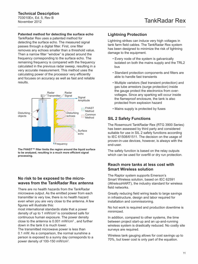
Patented method for detecting the surface echo TankRadar Rex uses a patented method for detecting the surface echo. The measured signal passes through a digital filter. First, one filter removes any echoes smaller than a threshold value. Then a narrow filter “window” is placed around the frequency corresponding to the surface echo. The remaining frequency is compared with the frequency calculated in the previous radar sweep, resulting in a very accurate measurement. This method uses the calculating power of the processor very efficiently and focuses on accuracy as well as fast and reliable results.
The FHAST™ filter limits the region around the liquid surface to be analyzed, resulting in a much more efficient signal processing.
No risk to be exposed to the micro-waves from the TankRadar Rex antennaThere are no health hazards from the TankRadar microwave output. As the emitted power from each transmitter is very low, there is no health hazard even when you are very close to the antenna. A few figures will illustrate this: most international standards state that a power density of up to 1 mW/cm2 is considered safe for continuous human exposure. The power density close to the antenna is 0.001 mW/cm2 , and further down in the tank it is much lower. The transmitted microwave power is less than 0.1 mW. As a comparison, the normal sunshine a person is exposed to a sunny day corresponds to a power density of 100-150 mW/cm2.
Lightning ProtectionLightning strikes can induce very high voltages in tank farm field cables. The TankRadar Rex system has been designed to minimize the risk of lightning damage to the equipment.
• Every node of the system is galvanically isolated on both the mains supply and the TRL2 bus
• Standard protection components and filters are able to handle fast transients
• Multiple varistors (fast transient protection) and gas tube arrestors (surge protection) inside the gauge protect the electronics from over-voltages. Since any sparking will occur inside the flameproof enclosure, the tank is also protected from explosion hazard
• Mains supply is protected by fuses
SIL 2 Safety FunctionsThe Rosemount TankRadar Rex (RTG 3900 Series) has been assessed by third party and considered suitable for use in SIL 2 safety functions according to IEC 61508/61511. The decision on the usage of proven-in-use devices, however, is always with the end-user.
The safety function is based on the relay outputs which can be used for overfill or dry run protection.
Reach more tanks at less cost with Smart Wireless solutionThe Raptor system supports Emerson’s Smart Wireless solution, based on IEC 62591 (WirelessHART), the industry standard for wireless field networks.
Greatly reducing field wiring leads to large savings in infrastructure, design and labor required for installation and commissioning.
No hot work is required and production downtime is minimized.
In addition, compared to other systems, the time between project start-up and an up-and-running wireless system is drastically reduced. No costly site surveys are required.
Wireless tank gauging allows for cost savings up to 70%, but lower cost is only part of the equation.
TankRadar RexTechnical Description
703010En, Ed. 5, Rev BNovember 2012
12
Better Utilization of Tank Capacity
Wireless functionality allows tank gauging data from remotely located tanks, previously collected manually or not at all, to be integrated into the system. This results in a more efficient tank capacity utilization, better inventory and loss control.
Intelligent Self-organizing Field Network Increases Reliability
A Smart Wireless device can transmit its own data as well as relay information from other devices in the network.
The self-organizing field network automatically finds the best way around any fixed or temporary obstacle.
Nodes can identify a network, join it, and self-organize into dynamic communication paths. Reliability actually increases when the network expands – the more devices, the more communication paths.
This results in a data reliability of more than 99% – even in a harsh and dynamic environment.
Smart Wireless for More Secure Data Transmission
Emerson’s Smart Wireless field network is designed for best-in-class security. Data is protected by 128-bit encryption, authentication, verification, anti-jamming, and key management.
With this type of design, the field network can offer a higher level of security than many traditional wired networks.
Wireless Connection of Tank Gauging Equipment
The Smart Wireless Gateway is the network manager that provides an interface between field devices and the TankMaster inventory software or host / DCS systems.
A single gateway supports up to 100 nodes.
Each wireless node in the tank gauging system consists of a TankRadar Rex gauge connected to mains power and supplied with a Smart Wireless THUM™ Adapter.
The wireless transmission supports important measurement data handled by the gauge, such as level, temperature, water level and pressure.
The tank gauging system can be complemented with other wireless devices, such as pressure transmitters and temperature sensors.
The THUM adapter can route any data to the radar gauge which allows full configuration and diagnostics using the AMS software or a Field Communicator.
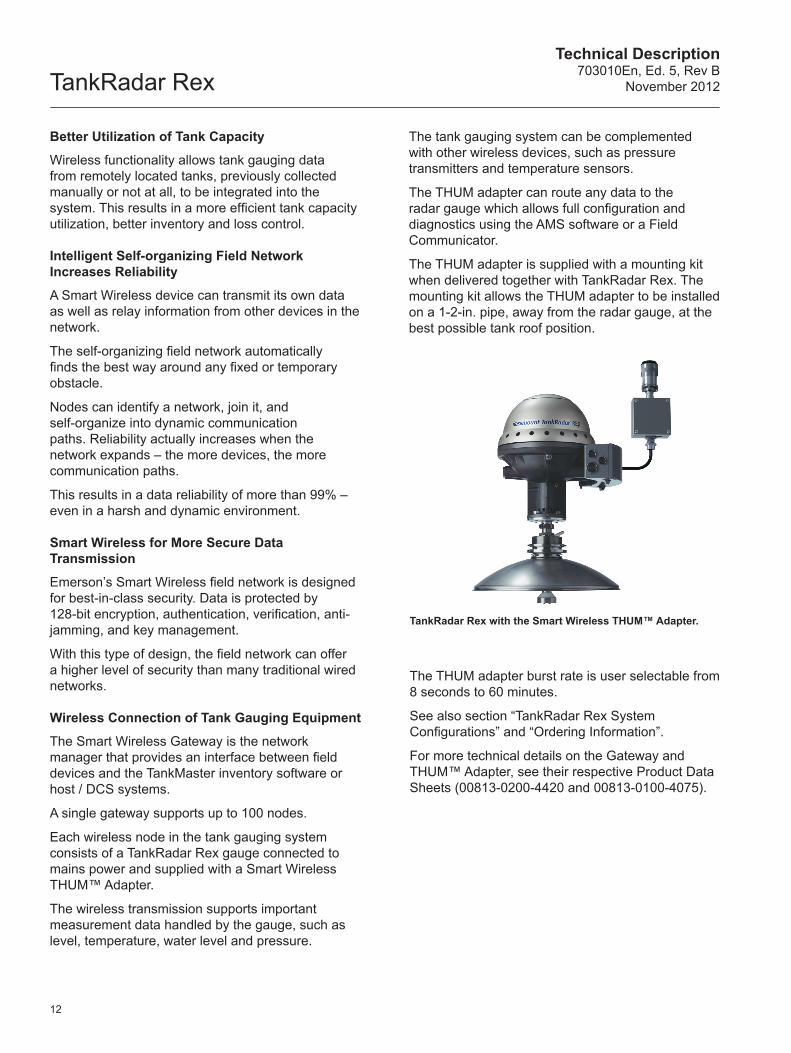
The THUM adapter is supplied with a mounting kit when delivered together with TankRadar Rex. The mounting kit allows the THUM adapter to be installed on a 1-2-in. pipe, away from the radar gauge, at the best possible tank roof position.
TankRadar Rex with the Smart Wireless THUM™ Adapter.
The THUM adapter burst rate is user selectable from 8 seconds to 60 minutes.
See also section “TankRadar Rex System Configurations” and “Ordering Information”.
For more technical details on the Gateway and THUM™ Adapter, see their respective Product Data Sheets (00813-0200-4420 and 00813-0100-4075).
Technical Description703010En, Ed. 5, Rev BNovember 2012 TankRadar Rex
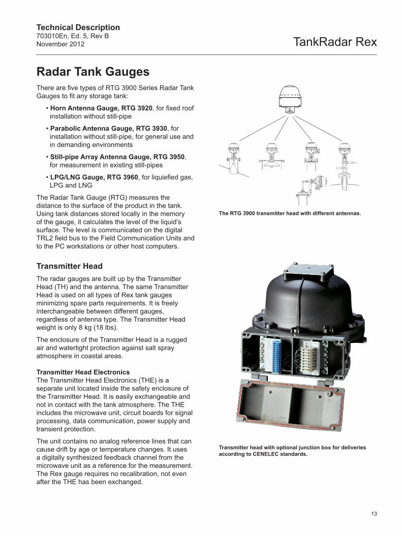
Transmitter head with optional junction box for deliveries according to CENELEC standards.
13
The RTG 3900 transmitter head with different antennas.
There are five types of RTG 3900 Series Radar Tank Gauges to fit any storage tank:
• Horn Antenna Gauge, RTG 3920, for fixed roof installation without still-pipe
• Parabolic Antenna Gauge, RTG 3930, for installation without still-pipe, for general use and in demanding environments
• Still-pipe Array Antenna Gauge, RTG 3950, for measurement in existing still-pipes
• LPG/LNG Gauge, RTG 3960, for liquiefied gas, LPG and LNG
The Radar Tank Gauge (RTG) measures the distance to the surface of the product in the tank. Using tank distances stored locally in the memory of the gauge, it calculates the level of the liquid’s surface. The level is communicated on the digital TRL2 field bus to the Field Communication Units and to the PC workstations or other host computers.
Transmitter HeadThe radar gauges are built up by the Transmitter Head (TH) and the antenna. The same Transmitter Head is used on all types of Rex tank gauges minimizing spare parts requirements. It is freely interchangeable between different gauges, regardless of antenna type. The Transmitter Head weight is only 8 kg (18 lbs).
The enclosure of the Transmitter Head is a rugged air and watertight protection against salt spray atmosphere in coastal areas.
Transmitter Head ElectronicsThe Transmitter Head Electronics (THE) is a separate unit located inside the safety enclosure of the Transmitter Head. It is easily exchangeable and not in contact with the tank atmosphere. The THE includes the microwave unit, circuit boards for signal processing, data communication, power supply and transient protection.
The unit contains no analog reference lines that can cause drift by age or temperature changes. It uses a digitally synthesized feedback channel from the microwave unit as a reference for the measurement. The Rex gauge requires no recalibration, not even after the THE has been exchanged.
Radar Tank Gauges
TankRadar RexTechnical Description
703010En, Ed. 5, Rev BNovember 2012
14
Motherboard
Transformer Rectifier Card
Field Communication Card
Signal Processing Card
Analog Processing Card
Transmitter Interface Card
Temperature Multiplexing Card
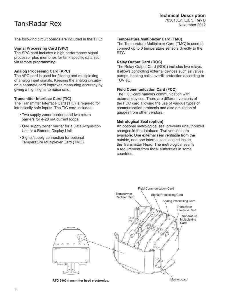
RTG 3900 transmitter head electronics.
The following circuit boards are included in the THE:
Signal Processing Card (SPC)The SPC card includes a high performance signal processor plus memories for tank specific data set via remote programming.
Analog Processing Card (APC)The APC card is used for filtering and multiplexing of analog input signals. Keeping the analog circuitry on a separate card improves measuring accuracy by giving a high signal to noise ratio.
Transmitter Interface Card (TIC) The Transmitter Interface Card (TIC) is required for intrinsically safe inputs. The TIC card includes:
• Two supply zener barriers and two return barriers for 4-20 mA current loops
• One supply zener barrier for a Data Acquisition Unit or a Remote Display Unit
• Signal/supply connection for optional Temperature Multiplexer Card (TMC)
Temperature Multiplexer Card (TMC)The Temperature Multiplexer Card (TMC) is used to connect up to 6 temperature sensors directly to the RTG.
Relay Output Card (ROC)The Relay Output Card (ROC) includes two relays. It allows controlling external devices such as valves, pumps, heating coils, overfill protection according to TÜV etc.
Field Communication Card (FCC)The FCC card handles communication with external devices. There are different versions of the FCC card allowing the use of various types of communication protocols and also emulation of gauges from other vendors.
Metrological Seal (option)An optional metrological seal prevents unauthorized changes in the database. Two versions are available; One external seal verifiable from the outside, and one internal seal located inside the Transmitter Head. The metrological seal is a requirement from fiscal authorities in some countries.
Technical Description703010En, Ed. 5, Rev BNovember 2012 TankRadar Rex
15
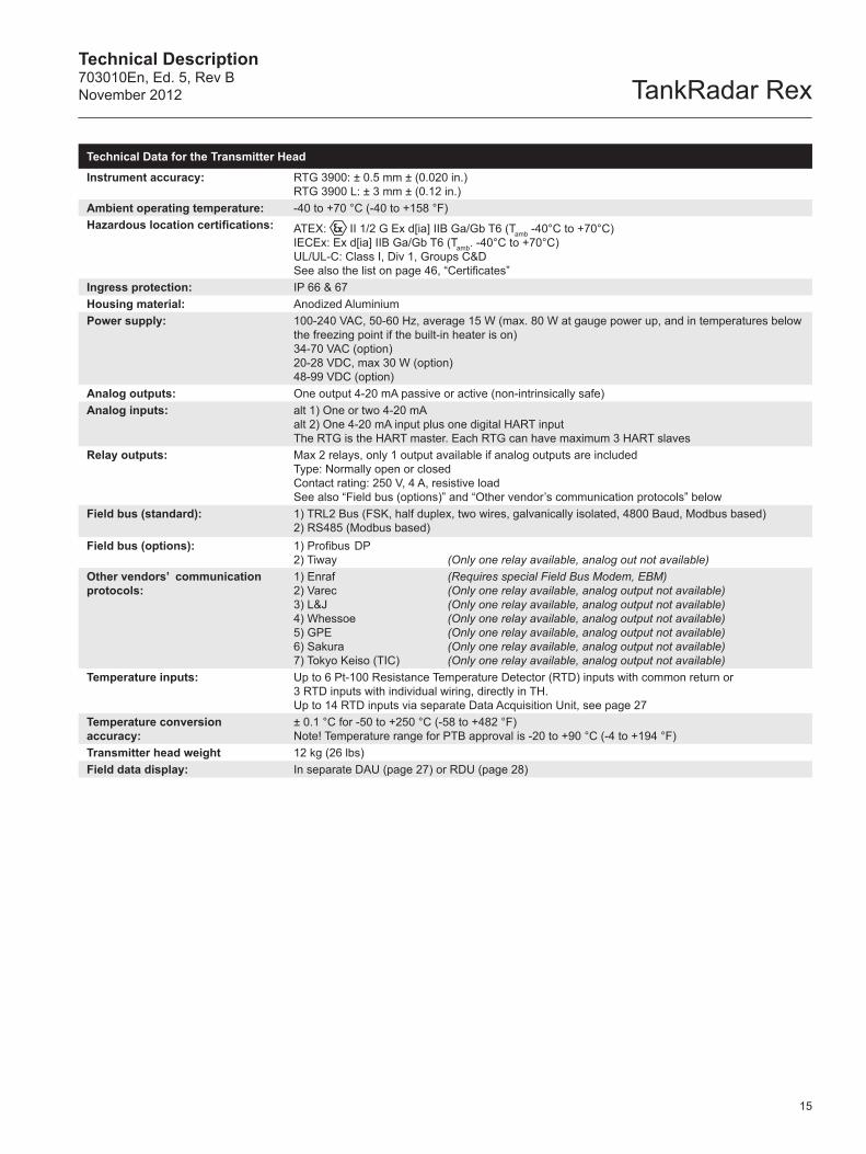
Technical Data for the Transmitter Head
Instrument accuracy: RTG 3900: ± 0.5 mm ± (0.020 in.)RTG 3900 L: ± 3 mm ± (0.12 in.)
Ambient operating temperature: -40 to +70 °C (-40 to +158 °F)Hazardous location certifications: ATEX: II 1/2 G Ex d[ia] IIB Ga/Gb T6 (Tamb -40°C to +70°C)
IECEx: Ex d[ia] IIB Ga/Gb T6 (Tamb. -40°C to +70°C)UL/UL-C: Class I, Div 1, Groups C&DSee also the list on page 46, “Certificates”
Ingress protection: IP 66 & 67Housing material: Anodized AluminiumPower supply: 100-240 VAC, 50-60 Hz, average 15 W (max. 80 W at gauge power up, and in temperatures below
the freezing point if the built-in heater is on) 34-70 VAC (option) 20-28 VDC, max 30 W (option)48-99 VDC (option)
Analog outputs: One output 4-20 mA passive or active (non-intrinsically safe)Analog inputs: alt 1) One or two 4-20 mA
alt 2) One 4-20 mA input plus one digital HART inputThe RTG is the HART master. Each RTG can have maximum 3 HART slaves
Relay outputs: Max 2 relays, only 1 output available if analog outputs are included Type: Normally open or closedContact rating: 250 V, 4 A, resistive load See also “Field bus (options)” and “Other vendor’s communication protocols” below
Field bus (standard): 1) TRL2 Bus (FSK, half duplex, two wires, galvanically isolated, 4800 Baud, Modbus based)2) RS485 (Modbus based)
Field bus (options): 1) Profibus DP2) Tiway (Only one relay available, analog out not available)
Other vendors’ communication protocols:
1) Enraf
2) Varec
3) L&J
4) Whessoe
5) GPE
6) Sakura
7) Tokyo Keiso (TIC)
(Requires special Field Bus Modem, EBM)(Only one relay available, analog output not available)(Only one relay available, analog output not available)(Only one relay available, analog output not available)(Only one relay available, analog output not available)(Only one relay available, analog output not available)(Only one relay available, analog output not available)
Temperature inputs: Up to 6 Pt-100 Resistance Temperature Detector (RTD) inputs with common return or 3 RTD inputs with individual wiring, directly in TH. Up to 14 RTD inputs via separate Data Acquisition Unit, see page 27
Temperature conversion accuracy:
± 0.1 °C for -50 to +250 °C (-58 to +482 °F) Note! Temperature range for PTB approval is -20 to +90 °C (-4 to +194 °F)
Transmitter head weight 12 kg (26 lbs)Field data display: In separate DAU (page 27) or RDU (page 28)
TankRadar RexTechnical Description
703010En, Ed. 5, Rev BNovember 2012
16
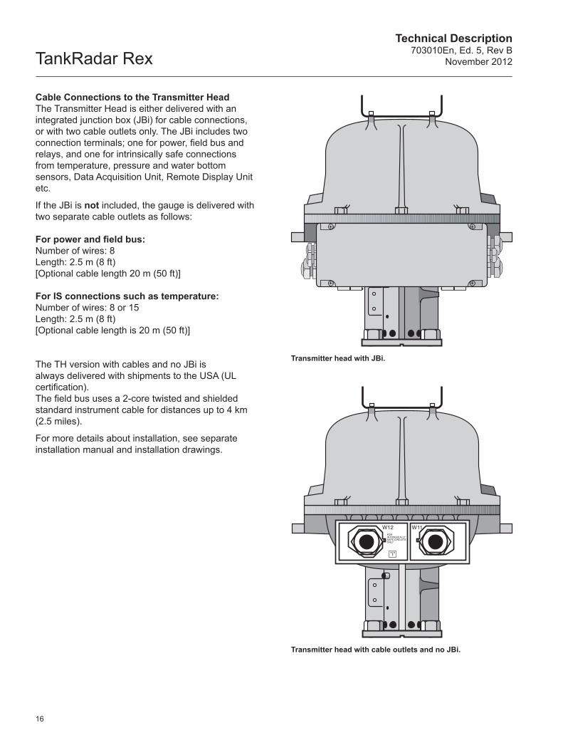
Cable Connections to the Transmitter HeadThe Transmitter Head is either delivered with an integrated junction box (JBi) for cable connections, or with two cable outlets only. The JBi includes two connection terminals; one for power, field bus and relays, and one for intrinsically safe connections from temperature, pressure and water bottom sensors, Data Acquisition Unit, Remote Display Unit etc.
If the JBi is not included, the gauge is delivered with two separate cable outlets as follows:
For power and field bus:Number of wires: 8 Length: 2.5 m (8 ft) [Optional cable length 20 m (50 ft)]
For IS connections such as temperature:Number of wires: 8 or 15 Length: 2.5 m (8 ft) [Optional cable length is 20 m (50 ft)]
The TH version with cables and no JBi is always delivered with shipments to the USA (UL certification). The field bus uses a 2-core twisted and shielded standard instrument cable for distances up to 4 km (2.5 miles).
For more details about installation, see separate installation manual and installation drawings.
Transmitter head with JBi.
Transmitter head with cable outlets and no JBi.
Technical Description703010En, Ed. 5, Rev BNovember 2012 TankRadar Rex
V
MADE IN SWEDEN
Ex
Junction Box Type JBI IP 65
EEx e[ia] IIC T6PTB Nr. Ex-97.D.3131
Tamb = -40 to +70C"DO NOT OPEN WHILE ENERGIZED"
1/2"NPT
1/2"NPT
3/4"NPT
1/2"NPT 3/4"
NPT
3/4"NPT
TAG NO:
EEx ia II C T4Tamb = -40 to +65CBASEEFAEx91C2069Umax:in = 28 VDC Wmax:in = 1.3 WImas:in = 394 mADCCeq = 0 Leq = 0
Serial no: UI:
For intrinsically safe circuits only
Data Acquisition Unit Type DAU 2130
Hazardous Location Class I Gorup Cand D.T emperature Code T4.The deviceprovides intrinsically safe outputs.See control drawing 9150 057-901Warning: any substitution of any componentsmay impair intrinsic safety.See service manualAmbient temperature -40 to +65 C Listed 9390
U LEx
MADE IN SWEDEN
©
DAU
Analog InputsTH
Analog Outputs
TRL2 Bus
Power
17
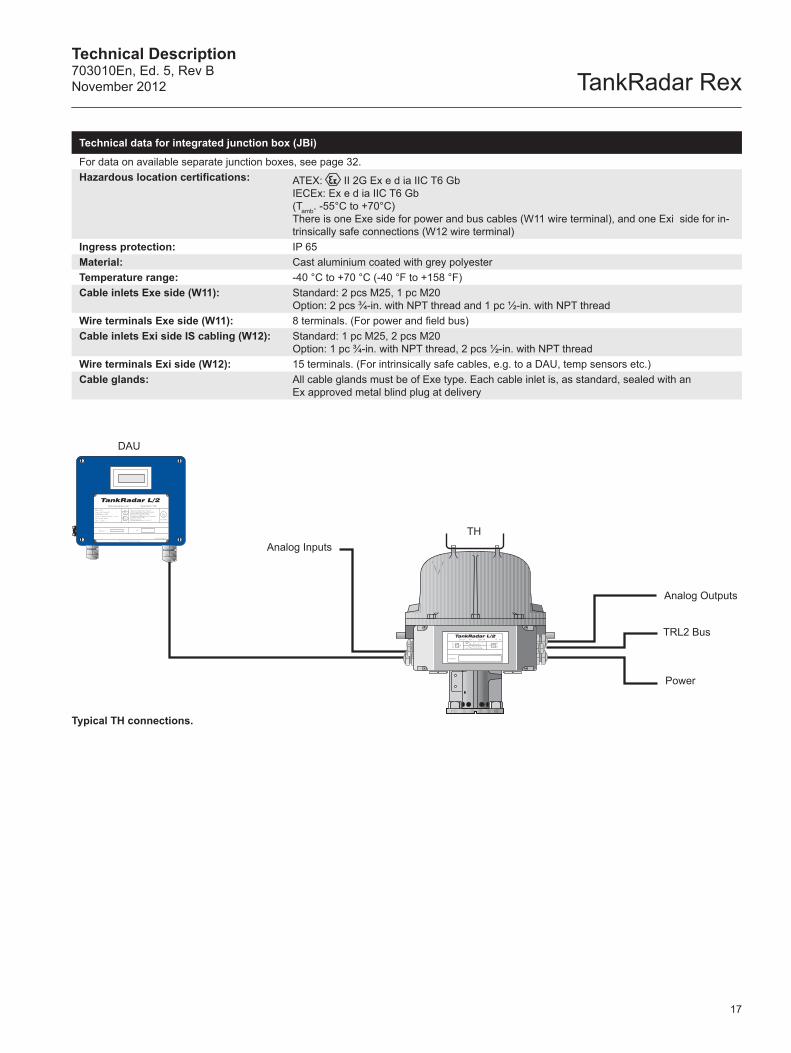
Typical TH connections.
Technical data for integrated junction box (JBi)
For data on available separate junction boxes, see page 32.Hazardous location certifications: ATEX: II 2G Ex e d ia IIC T6 Gb
IECEx: Ex e d ia IIC T6 Gb (Tamb. -55°C to +70°C)There is one Exe side for power and bus cables (W11 wire terminal), and one Exi side for in-trinsically safe connections (W12 wire terminal)
Ingress protection: IP 65Material: Cast aluminium coated with grey polyesterTemperature range: -40 °C to +70 °C (-40 °F to +158 °F)Cable inlets Exe side (W11): Standard: 2 pcs M25, 1 pc M20
Option: 2 pcs ¾-in. with NPT thread and 1 pc ½-in. with NPT threadWire terminals Exe side (W11): 8 terminals. (For power and field bus)Cable inlets Exi side IS cabling (W12): Standard: 1 pc M25, 2 pcs M20
Option: 1 pc ¾-in. with NPT thread, 2 pcs ½-in. with NPT threadWire terminals Exi side (W12): 15 terminals. (For intrinsically safe cables, e.g. to a DAU, temp sensors etc.)Cable glands: All cable glands must be of Exe type. Each cable inlet is, as standard, sealed with an
Ex approved metal blind plug at delivery
TankRadar RexTechnical Description
703010En, Ed. 5, Rev BNovember 2012
mm (inches)
Weather Protection HoodTransmitter
Head
Tank Nozzle Min. 8-inch
Horn Antenna
175 (6.9)
780
(30.
7)
18
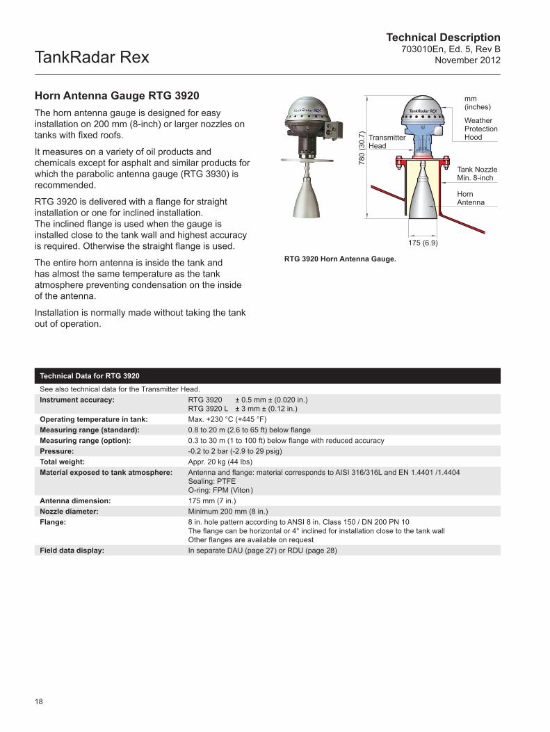
Horn Antenna Gauge RTG 3920 The horn antenna gauge is designed for easy installation on 200 mm (8-inch) or larger nozzles on tanks with fixed roofs.
It measures on a variety of oil products and chemicals except for asphalt and similar products for which the parabolic antenna gauge (RTG 3930) is recommended.
RTG 3920 is delivered with a flange for straight installation or one for inclined installation. The inclined flange is used when the gauge is installed close to the tank wall and highest accuracy is required. Otherwise the straight flange is used.
The entire horn antenna is inside the tank and has almost the same temperature as the tank atmosphere preventing condensation on the inside of the antenna.
Installation is normally made without taking the tank out of operation.
RTG 3920 Horn Antenna Gauge.
Technical Data for RTG 3920
See also technical data for the Transmitter Head.Instrument accuracy: RTG 3920 ± 0.5 mm ± (0.020 in.)
RTG 3920 L ± 3 mm ± (0.12 in.)Operating temperature in tank: Max. +230 °C (+445 °F)Measuring range (standard): 0.8 to 20 m (2.6 to 65 ft) below flangeMeasuring range (option): 0.3 to 30 m (1 to 100 ft) below flange with reduced accuracyPressure: -0.2 to 2 bar (-2.9 to 29 psig)Total weight: Appr. 20 kg (44 lbs)Material exposed to tank atmosphere: Antenna and flange: material corresponds to AISI 316/316L and EN 1.4401 /1.4404
Sealing: PTFEO-ring: FPM (Viton )
Antenna dimension: 175 mm (7 in.)Nozzle diameter: Minimum 200 mm (8 in.)Flange: 8 in. hole pattern according to ANSI 8 in. Class 150 / DN 200 PN 10
The flange can be horizontal or 4° inclined for installation close to the tank wallOther flanges are available on request
Field data display: In separate DAU (page 27) or RDU (page 28)
Technical Description703010En, Ed. 5, Rev BNovember 2012 TankRadar Rex
mm (inches)Weather Protection Hood
Transmitter Head
Antenna Feeder
440 (17.3)
750
(29.
5)
Parabolic Reflector
19
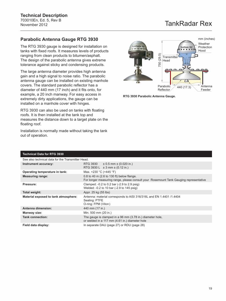
Parabolic Antenna Gauge RTG 3930The RTG 3930 gauge is designed for installation on tanks with fixed roofs. It measures levels of products ranging from clean products to bitumen/asphalt. The design of the parabolic antenna gives extreme tolerance against sticky and condensing products.
The large antenna diameter provides high antenna gain and a high signal to noise ratio. The parabolic antenna gauge can be installed on existing manhole covers. The standard parabolic reflector has a diameter of 440 mm (17 inch) and it fits onto, for example, a 20 inch manway. For easy access in extremely dirty applications, the gauge can be installed on a manhole cover with hinges.
RTG 3930 can also be used on tanks with floating roofs. It is then installed at the tank top and measures the distance down to a target plate on the floating roof.
Installation is normally made without taking the tank out of operation.
RTG 3930 Parabolic Antenna Gauge.
Technical Data for RTG 3930
See also technical data for the Transmitter Head.Instrument accuracy: RTG 3930 ± 0.5 mm ± (0.020 in.)
RTG 3930 L ± 3 mm ± (0.12 in.)Operating temperature in tank: Max. +230 °C (+445 °F)Measuring range: 0.8 to 40 m (2.6 to 130 ft) below flange.
For longer measuring range, please consult your Rosemount Tank Gauging representativePressure: Clamped: -0.2 to 0.2 bar (-2.9 to 2.9 psig)
Welded: -0.2 to 10 bar (-2.9 to 145 psig)Total weight: Appr. 25 kg (55 lbs)Material exposed to tank atmosphere: Antenna: material corresponds to AISI 316/316L and EN 1.4401 /1.4404
Sealing: PTFE O-ring: FPM (Viton )
Antenna dimension: 440 mm (17 in.)Manway size: Min. 500 mm (20 in.)Tank connection: The gauge is clamped in a 96 mm (3.78 in.) diameter hole,
or welded in a 117 mm (4.61 in.) diameter holeField data display: In separate DAU (page 27) or RDU (page 28)
TankRadar RexTechnical Description
703010En, Ed. 5, Rev BNovember 2012
510
(20.
1)
590 (23.2)
700
(27.
6)
Weather Protection Hood
Antenna
Pipe seen from above
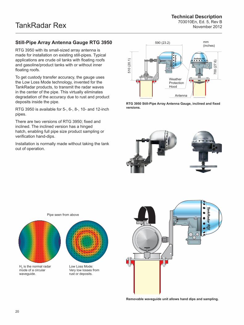
HII is the normal radarmode of a circular waveguide.
Low Loss Mode:Very low losses from rust or deposits.
mm (inches)
20
Still-Pipe Array Antenna Gauge RTG 3950RTG 3950 with its small-sized array antenna is made for installation on existing still-pipes. Typical applications are crude oil tanks with floating roofs and gasoline/product tanks with or without inner floating roofs.
To get custody transfer accuracy, the gauge uses the Low Loss Mode technology, invented for the TankRadar products, to transmit the radar waves in the center of the pipe. This virtually eliminates degradation of the accuracy due to rust and product deposits inside the pipe.
RTG 3950 is available for 5-, 6-, 8-, 10- and 12-inch pipes.
There are two versions of RTG 3950; fixed and inclined. The inclined version has a hinged hatch, enabling full pipe size product sampling or verification hand-dips.
Installation is normally made without taking the tank out of operation.
RTG 3950 Still-Pipe Array Antenna Gauge, inclined and fixed versions.
Removable waveguide unit allows hand dips and sampling.
Technical Description703010En, Ed. 5, Rev BNovember 2012 TankRadar Rex
mm (inch)
Weather Protection Hood
Transmitter Head
Pipe Cone
670
(26.
4)
Lower Flange
Pressure Transducer
300 (11.8)
6 inch Existing pressurevessel flange
Valve
4-inch orø 100 mmstill-pipe
21
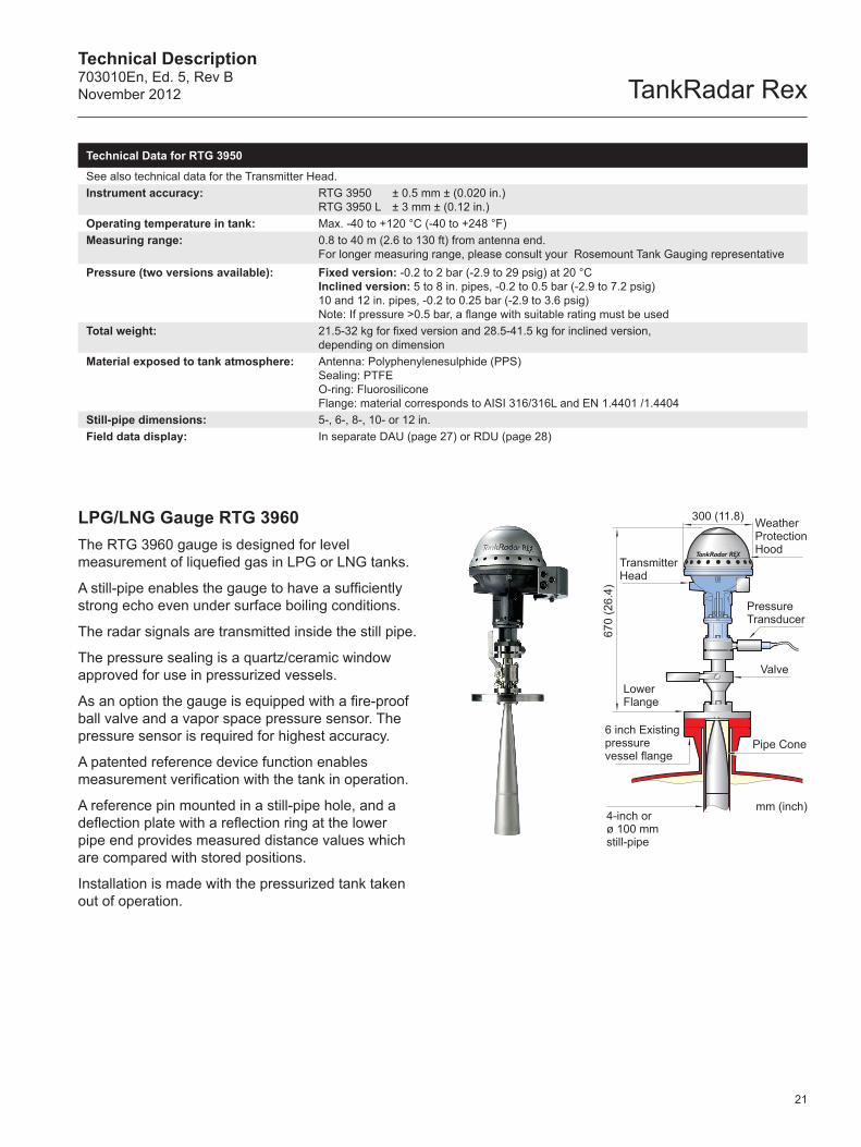
LPG/LNG Gauge RTG 3960The RTG 3960 gauge is designed for level measurement of liquefied gas in LPG or LNG tanks.
A still-pipe enables the gauge to have a sufficiently strong echo even under surface boiling conditions.
The radar signals are transmitted inside the still pipe.
The pressure sealing is a quartz/ceramic window approved for use in pressurized vessels.
As an option the gauge is equipped with a fire-proof ball valve and a vapor space pressure sensor. The pressure sensor is required for highest accuracy.
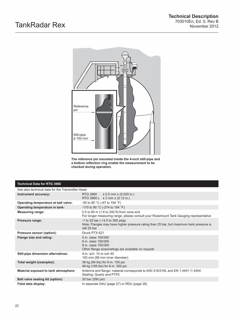
A patented reference device function enables measurement verification with the tank in operation.
A reference pin mounted in a still-pipe hole, and a deflection plate with a reflection ring at the lower pipe end provides measured distance values which are compared with stored positions.
Installation is made with the pressurized tank taken out of operation.
Technical Data for RTG 3950
See also technical data for the Transmitter Head.Instrument accuracy: RTG 3950 ± 0.5 mm ± (0.020 in.)
RTG 3950 L ± 3 mm ± (0.12 in.)Operating temperature in tank: Max. -40 to +120 °C (-40 to +248 °F)Measuring range: 0.8 to 40 m (2.6 to 130 ft) from antenna end.
For longer measuring range, please consult your Rosemount Tank Gauging representativePressure (two versions available): Fixed version: -0.2 to 2 bar (-2.9 to 29 psig) at 20 °C
Inclined version: 5 to 8 in. pipes, -0.2 to 0.5 bar (-2.9 to 7.2 psig)10 and 12 in. pipes, -0.2 to 0.25 bar (-2.9 to 3.6 psig)Note: If pressure >0.5 bar, a flange with suitable rating must be used
Total weight: 21.5-32 kg for fixed version and 28.5-41.5 kg for inclined version,depending on dimension
Material exposed to tank atmosphere: Antenna: Polyphenylenesulphide (PPS) Sealing: PTFEO-ring: FluorosiliconeFlange: material corresponds to AISI 316/316L and EN 1.4401 /1.4404
Still-pipe dimensions: 5-, 6-, 8-, 10- or 12 in.Field data display: In separate DAU (page 27) or RDU (page 28)
TankRadar RexTechnical Description
703010En, Ed. 5, Rev BNovember 2012
Ex
Reference pin
Still-pipeø 100 mm
22
The reference pin mounted inside the 4-inch still-pipe and a bottom reflection ring enable the measurement to be checked during operation.
Technical Data for RTG 3960
See also technical data for the Transmitter Head.Instrument accuracy: RTG 3960 ± 0.5 mm ± (0.020 in.)
RTG 3960 L ± 3 mm ± (0.12 in.)Operating temperature at ball valve: -55 to 90 °C (-67 to 194 °F)Operating temperature in tank: -170 to 90 °C (-274 to 194 °F)Measuring range: 0.5 to 60 m (1.6 to 200 ft) from cone end
For longer measuring range, please consult your Rosemount Tank Gauging representativePressure range: -1 to 25 bar (-14.5 to 365 psig)
Note: Flanges may have higher pressure rating than 25 bar, but maximum tank pressure is still 25 bar
Pressure sensor (option): Druck PTX 621Flange size and rating: 4 in. class 150/300
6 in. class 150/3008 in. class 150/300Other flange sizes/ratings are available on request
Still-pipe dimension alternatives: 4-in. sch. 10 or sch 40 100 mm (99 mm inner diameter)
Total weight (examples): 38 kg (84 lbs) for 6-in. 150 psi48 kg (106 lbs) for 6-in. 300 psi
Material exposed to tank atmosphere: Antenna and flange: material corresponds to AISI 316/316L and EN 1.4401 /1.4404Sealing: Quartz and PTFE
Ball valve sealing kit (option): 20 bar (290 psi)Field data display: In separate DAU (page 27) or RDU (page 28)
Technical Description703010En, Ed. 5, Rev BNovember 2012 TankRadar Rex
Temperature measurement
RTG DAU RTG
JB
Multiple spot temperature sensor
Anchor weight or alternatively a loop with steel wire pulled through and to top of tank
Multiple spot temperature sensor
Anchor weight or alternatively a loop with steel wire pulled through and to top of tank
23
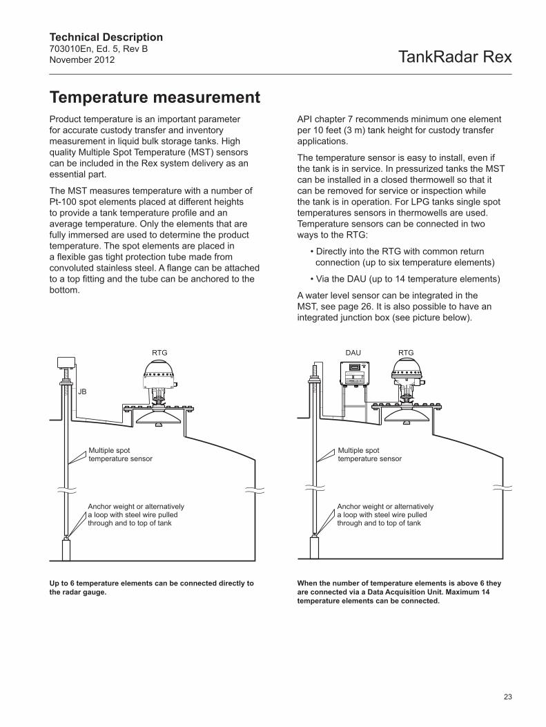
Product temperature is an important parameter for accurate custody transfer and inventory measurement in liquid bulk storage tanks. High quality Multiple Spot Temperature (MST) sensors can be included in the Rex system delivery as an essential part.
The MST measures temperature with a number of Pt-100 spot elements placed at different heights to provide a tank temperature profile and an average temperature. Only the elements that are fully immersed are used to determine the product temperature. The spot elements are placed in a flexible gas tight protection tube made from convoluted stainless steel. A flange can be attached to a top fitting and the tube can be anchored to the bottom.
API chapter 7 recommends minimum one element per 10 feet (3 m) tank height for custody transfer applications.
The temperature sensor is easy to install, even if the tank is in service. In pressurized tanks the MST can be installed in a closed thermowell so that it can be removed for service or inspection while the tank is in operation. For LPG tanks single spot temperatures sensors in thermowells are used. Temperature sensors can be connected in two ways to the RTG:
• Directly into the RTG with common return connection (up to six temperature elements)
• Via the DAU (up to 14 temperature elements)
A water level sensor can be integrated in the MST, see page 26. It is also possible to have an integrated junction box (see picture below).
When the number of temperature elements is above 6 they are connected via a Data Acquisition Unit. Maximum 14 temperature elements can be connected.
Up to 6 temperature elements can be connected directly to the radar gauge.
TankRadar RexTechnical Description
703010En, Ed. 5, Rev BNovember 2012
Still-pipe
Temperature (T) °C (°F)
Din B
Din A
1/6 Din B1/10 Din B 0.2 (0.36)
0.4 (0.72)
0.6 (1.08)
0.8 (1.44)
1.0 (1.80)
1.2 (2.16)
1.4 (2.52)
1.6 (2.88)
1.8 (3.24)
± Deviation °C (°F)
0.2 (0.36)
0.4 (0.72)
0.6 (1.08)
0.8 (1.44)
1.0 (1.80)
1.2 (2.16)
1.4 (2.52)
1.6 (2.88)
1.8 (3.24)
-100 (-148) -50 (-58) 0 (32) 50 (122) 150 (302)100 (212) 200 (392) 250 (482)
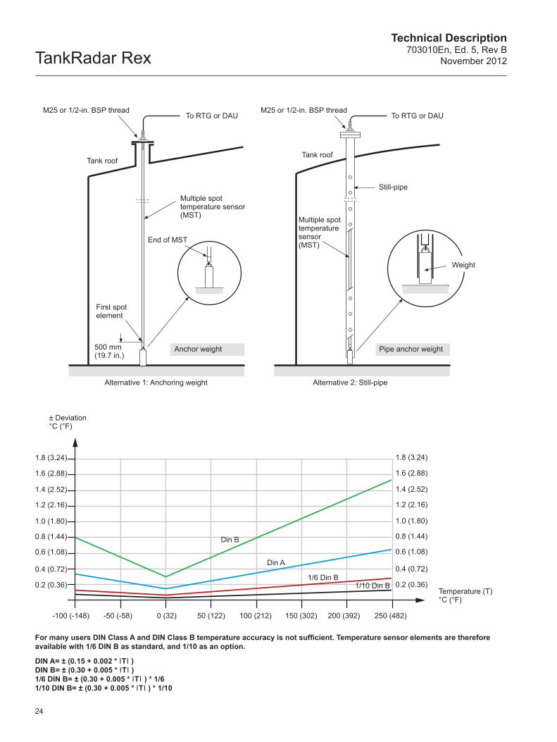
Multiple spot temperature sensor (MST)
End of MST
M25 or 1/2-in. BSP thread
First spot element
500 mm (19.7 in.)
Anchor weight
Alternative 1: Anchoring weight
Tank roof
Multiple spot temperature sensor (MST)
Alternative 2: Still-pipe
Pipe anchor weight
Weight
M25 or 1/2-in. BSP threadTo RTG or DAUTo RTG or DAU
Tank roof
24
For many users DIN Class A and DIN Class B temperature accuracy is not sufficient. Temperature sensor elements are therefore available with 1/6 DIN B as standard, and 1/10 as an option.
DIN A= ± (0.15 + 0.002 * ITI )DIN B= ± (0.30 + 0.005 * ITI )1/6 DIN B= ± (0.30 + 0.005 * ITI ) * 1/61/10 DIN B= ± (0.30 + 0.005 * ITI ) * 1/10
Technical Description703010En, Ed. 5, Rev BNovember 2012 TankRadar Rex
25
Technical Data for Multiple Spot Temperature Sensor
Elements type: Pt-100 spot elements according to EN 60751Accuracy: 1/6 DIN Class B (standard), 1/10 DIN Class B (option). See diagram on previous pageOverall temperature range (standard): -50 to 120 °C (-58 to 248 °F)Overall temperature range (optional): -20 to 250 °C (-4 to 482 °F)
-170 to 100 °C (-274 to 212 °F)Number of elements: 6 elements per MST as standard, and 14 elements as maximum for each MSTOverall length: 0.95-70 m (3.1-230 ft)Sheath diameter: ¾-in. (standard), 1-in. (always with WLS)Top fitting: Steel pipe with M25 x 1.5 or 1/2-in. BSP thread. Thread length 253 mm (10.0 in.)Tank opening: Min. ø 2-in. (50.8 mm)Outer material: Stainless steel, AISI 316Flange (option): 1½ to 4 in.Lead wire length: 3 m (9.8 ft). Longer wires optional, max 10 m (32.8 ft)No of wires: 3 independent wires per element or 1 wire per element plus 2 common return wiresBottom weight: 2.5-15 kg (5.5-33 lbs). 2.5-4 kg (5.5-9 lbs) for still-pipe installationConnection to Rex system: Max. 14 elements via DAU, or max 6 elements with common return directly to Rex Gauge
(max. 3 elements with independent wires)Hazardous location certifications: MST: II 1G Ex ia IIC T2/T4. T4 for standard temperature range
Cryo: II 1G Ex ia IIC T5Designed according to: IEC 751 and ATEX Directive 94/9/EC
Technical Data for Single Spot Temperature Sensor – LPG tanks
Element type: Pt-100, 1/6 DIN Class B or optional 1/10 DIN Class B, 3 wireTemperature range (standard): -50 to 260 °C (-58 to 500 °F)Temperature range (optional): -50 to 400 °C (-58 to 752 °F)Sheath: 8 mm (0.31 in.), 9 mm (0.35 in.) or 11 mm (0.43 in.) outer diameterSheath material: Stainless steel AISI 316TIMounting thread: ½-in. NPT or BSP threadLength (standard): 500 mm (20 in.)Thermowell: 16 mm (0.63 in.) outer diameter as standardThermowell material: Stainless steel AISI 316TIDesigned according to: IEC 751 and ATEX Directive 94/9/EC
TankRadar RexTechnical Description
703010En, Ed. 5, Rev BNovember 2012
Water interface measurement
Optional temperaturespot element Pt 100 300 (11.8) from eye bolt
Sensor electrode
Anchoringfacility (eye bolt)
The open WLS seen from below
Protective cablehose or multiplespot temperature
sensor
Act
ive
leng
th (L
) =S
tand
ard:
500
(19.
96)
Opt
ion:
1
000
(39.
37) o
r 150
0 (5
9.96
)
Act
ive
leng
th (L
) =S
tand
ard:
500
(19.
96)
Opt
ion:
1
000
(39.
37) o
r 150
0 (5
9.96
)
L+14
0 (5
.5)
L+14
0 (5
.5)
ø 48 (1.90) ø 38 (1.50)Multiple spot temperature sensor
Tank wall
Interface levelWLS
Open model Closed model
26
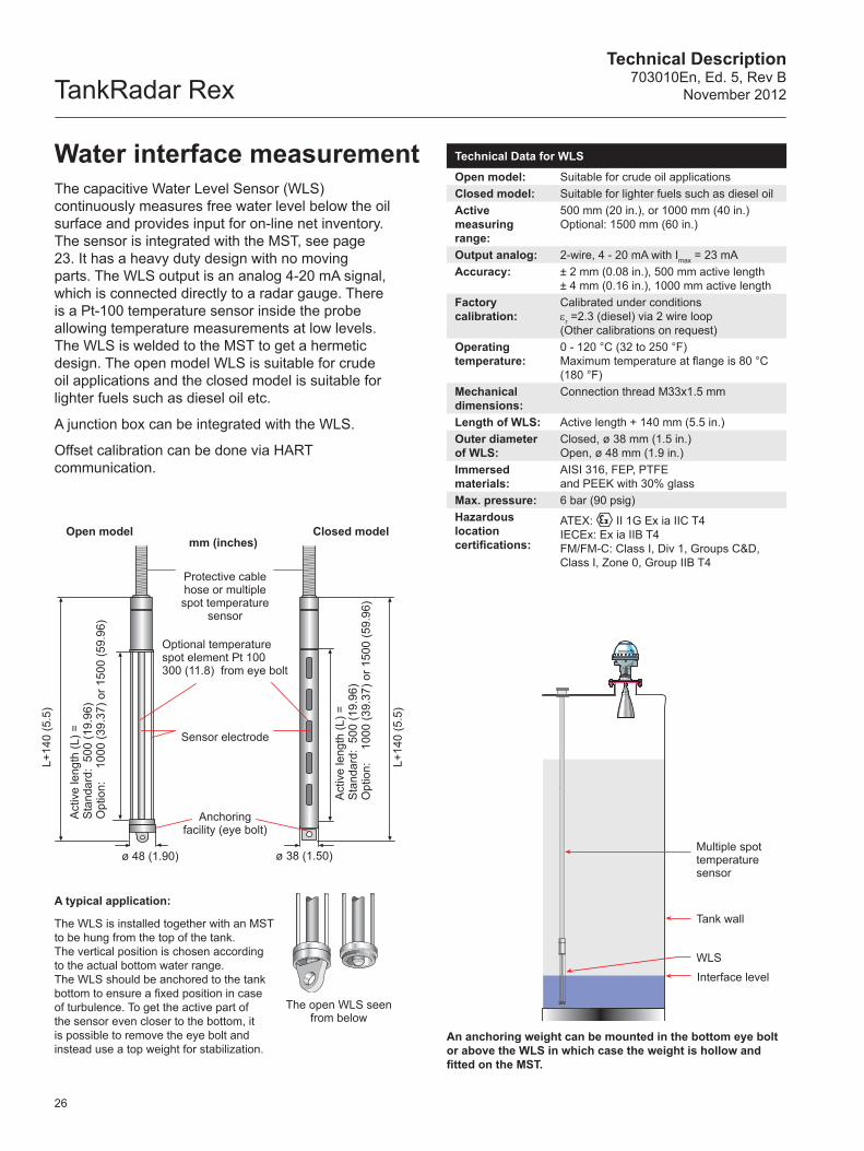
The capacitive Water Level Sensor (WLS) continuously measures free water level below the oil surface and provides input for on-line net inventory. The sensor is integrated with the MST, see page 23. It has a heavy duty design with no moving parts. The WLS output is an analog 4-20 mA signal, which is connected directly to a radar gauge. There is a Pt-100 temperature sensor inside the probe allowing temperature measurements at low levels. The WLS is welded to the MST to get a hermetic design. The open model WLS is suitable for crude oil applications and the closed model is suitable for lighter fuels such as diesel oil etc.
A junction box can be integrated with the WLS.
Offset calibration can be done via HART communication.
A typical application:
The WLS is installed together with an MST to be hung from the top of the tank. The vertical position is chosen according to the actual bottom water range. The WLS should be anchored to the tank bottom to ensure a fixed position in case of turbulence. To get the active part of the sensor even closer to the bottom, it is possible to remove the eye bolt and instead use a top weight for stabilization.
An anchoring weight can be mounted in the bottom eye bolt or above the WLS in which case the weight is hollow and fitted on the MST.
Technical Data for WLS
Open model: Suitable for crude oil applicationsClosed model: Suitable for lighter fuels such as diesel oilActive measuring range:
500 mm (20 in.), or 1000 mm (40 in.)Optional: 1500 mm (60 in.)
Output analog: 2-wire, 4 - 20 mA with Imax = 23 mAAccuracy: ± 2 mm (0.08 in.), 500 mm active length
± 4 mm (0.16 in.), 1000 mm active lengthFactory calibration:
Calibrated under conditionsεr =2.3 (diesel) via 2 wire loop (Other calibrations on request)
Operating temperature:
0 - 120 °C (32 to 250 °F)Maximum temperature at flange is 80 °C(180 °F)
Mechanical dimensions:
Connection thread M33x1.5 mm
Length of WLS: Active length + 140 mm (5.5 in.)Outer diameterof WLS:
Closed, ø 38 mm (1.5 in.) Open, ø 48 mm (1.9 in.)
Immersed materials:
AISI 316, FEP, PTFEand PEEK with 30% glass
Max. pressure: 6 bar (90 psig)Hazardous location certifications:
ATEX: II 1G Ex ia IIC T4IECEx: Ex ia IIB T4FM/FM-C: Class I, Div 1, Groups C&D, Class I, Zone 0, Group IIB T4
mm (inches)
Technical Description703010En, Ed. 5, Rev BNovember 2012 TankRadar Rex
0.23
m (9
in.)
0.28 m (11 in.)
Cable glands (not for the US market)
LCD display for local read-out
27
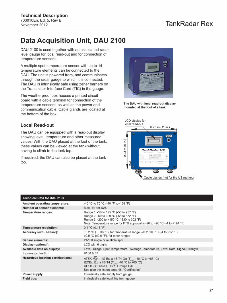
DAU 2100 is used together with an associated radar level gauge for local read-out and for connection of temperature sensors.
A multiple spot temperature sensor with up to 14 temperature elements can be connected to the DAU. The unit is powered from, and communicates through the radar gauge to which it is connected. The DAU is intrinsically safe using zener barriers on the Transmitter Interface Card (TIC) in the gauge.
The weatherproof box houses a printed circuit board with a cable terminal for connection of the temperature sensors, as well as the power and communication cable. Cable glands are located at the bottom of the box.
Local Read-outThe DAU can be equipped with a read-out display showing level, temperature and other measured values. With the DAU placed at the foot of the tank, these values can be viewed at the tank without having to climb to the tank top.
If required, the DAU can also be placed at the tank top.
The DAU with local read-out display mounted at the foot of a tank.
Data Acquisition Unit, DAU 2100
Technical Data for DAU 2100
Ambient operating temperature: -40 °C to 70 °C (-40 °F to+158 °F)Number of sensor elements: Max. 14 per DAUTemperature ranges: Range 1: -50 to 125 °C (-58 to 257 °F)
Range 2: -50 to 300 °C (-58 to 572 °F)Range 3: -200 to +150 °C (-330 to 302 °F)Note: Temperature range for PTB approval is -20 to +90 °C (-4 to +194 °F)
Temperature resolution: 0.1 °C (0.18 °F)Accuracy (excl. sensor): ±0.2 °C (±0.36 °F), for temperature range -20 to 100 °C (-4 to 212 °F)
±0.5 °C (±0.9 °F), for other rangesSensor elements: Pt-100 single or multiple spotDisplay (optional): LCD with 6 digitsAvailable data on display: Level, Ullage, Spot Temperature, Average Temperature, Level Rate, Signal StrengthIngress protection: IP 66 & 67Hazardous location certifications: ATEX: II 1G Ex ia IIB T4 Ga (Tamb. -40 °C to +65 °C)
IECEx: Ex ia IIB T4 (Tamb. -40 °C to +65 °C)UL/UL-C: Class I, Div 1, Groups C&D See also the list on page 46, “Certificates”
Power supply: Intrinsically safe supply from gaugeField bus: Intrinsically safe local line from gauge
TankRadar RexTechnical Description
703010En, Ed. 5, Rev BNovember 2012
6.767Level
m
Remote Display Unit, RDU 40
28
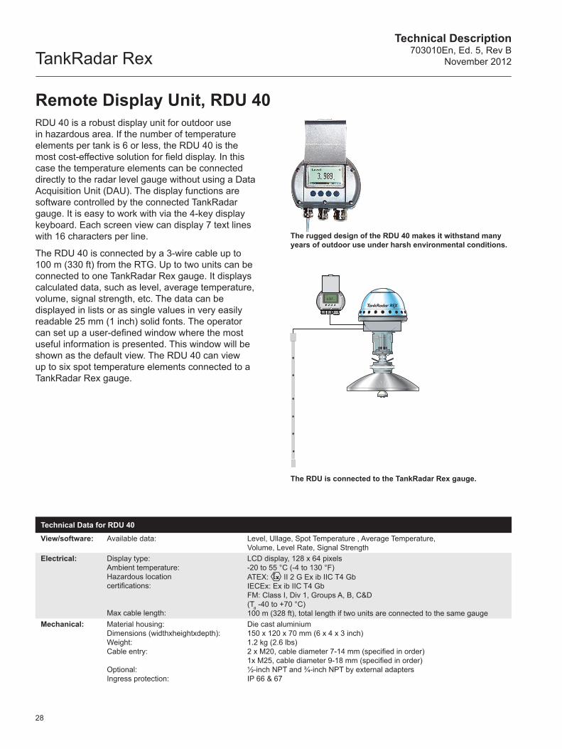
RDU 40 is a robust display unit for outdoor use in hazardous area. If the number of temperature elements per tank is 6 or less, the RDU 40 is the most cost-effective solution for field display. In this case the temperature elements can be connected directly to the radar level gauge without using a Data Acquisition Unit (DAU). The display functions are software controlled by the connected TankRadar gauge. It is easy to work with via the 4-key display keyboard. Each screen view can display 7 text lines with 16 characters per line.
The RDU 40 is connected by a 3-wire cable up to 100 m (330 ft) from the RTG. Up to two units can be connected to one TankRadar Rex gauge. It displays calculated data, such as level, average temperature, volume, signal strength, etc. The data can be displayed in lists or as single values in very easily readable 25 mm (1 inch) solid fonts. The operator can set up a user-defined window where the most useful information is presented. This window will be shown as the default view. The RDU 40 can view up to six spot temperature elements connected to a TankRadar Rex gauge.
The rugged design of the RDU 40 makes it withstand many years of outdoor use under harsh environmental conditions.
The RDU is connected to the TankRadar Rex gauge.
Technical Data for RDU 40
View/software: Available data: Level, Ullage, Spot Temperature , Average Temperature,Volume, Level Rate, Signal Strength
Electrical: Display type:Ambient temperature:Hazardous location certifications: Max cable length:
LCD display, 128 x 64 pixels -20 to 55 °C (-4 to 130 °F) ATEX: II 2 G Ex ib IIC T4 GbIECEx: Ex ib IIC T4 GbFM: Class I, Div 1, Groups A, B, C&D(Ta -40 to +70 °C)100 m (328 ft), total length if two units are connected to the same gauge
Mechanical: Material housing:Dimensions (widthxheightxdepth):Weight:Cable entry:
Optional:Ingress protection:
Die cast aluminium150 x 120 x 70 mm (6 x 4 x 3 inch)1.2 kg (2.6 lbs)2 x M20, cable diameter 7-14 mm (specified in order) 1x M25, cable diameter 9-18 mm (specified in order)½-inch NPT and ¾-inch NPT by external adaptersIP 66 & 67
Technical Description703010En, Ed. 5, Rev BNovember 2012 TankRadar Rex
Group buses
FCU
Field buses
0.28 m (11 in.)
0.23
m (9
in.)
Cable Inlets
29
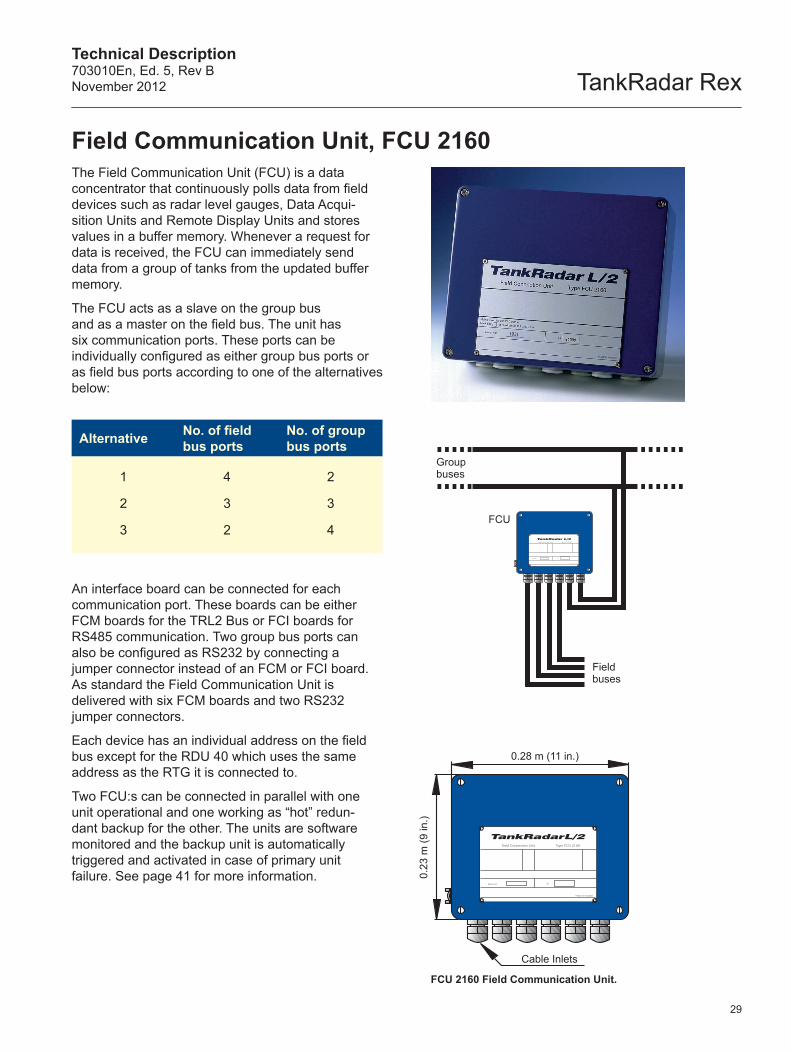
The Field Communication Unit (FCU) is a data concentrator that continuously polls data from field devices such as radar level gauges, Data Acqui-sition Units and Remote Display Units and stores values in a buffer memory. Whenever a request for data is received, the FCU can immediately send data from a group of tanks from the updated buffer memory.
The FCU acts as a slave on the group bus and as a master on the field bus. The unit has six communication ports. These ports can be individually configured as either group bus ports or as field bus ports according to one of the alternatives below:
Alternative No. of field bus ports
No. of group bus ports
1
2
3
4
3
2
2
3
4
An interface board can be connected for each communication port. These boards can be either FCM boards for the TRL2 Bus or FCI boards for RS485 communication. Two group bus ports can also be configured as RS232 by connecting a jumper connector instead of an FCM or FCI board. As standard the Field Communication Unit is delivered with six FCM boards and two RS232 jumper connectors.
Each device has an individual address on the field bus except for the RDU 40 which uses the same address as the RTG it is connected to.
Two FCU:s can be connected in parallel with one unit operational and one working as “hot” redun-dant backup for the other. The units are software monitored and the backup unit is automatically triggered and activated in case of primary unit failure. See page 41 for more information.
Field Communication Unit, FCU 2160
FCU 2160 Field Communication Unit.
TankRadar RexTechnical Description
703010En, Ed. 5, Rev BNovember 2012
30
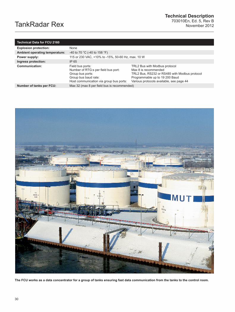
The FCU works as a data concentrator for a group of tanks ensuring fast data communication from the tanks to the control room.
Technical Data for FCU 2160
Explosion protection: NoneAmbient operating temperature: -40 to 70 °C (-40 to 158 °F)Power supply: 115 or 230 VAC, +10% to -15%, 50-60 Hz, max. 10 WIngress protection: IP 65Communication: Field bus ports:
Number of RTG:s per field bus port:Group bus ports:Group bus baud rate:Host communication via group bus ports:
TRL2 Bus with Modbus protocolMax 8 is recommendedTRL2 Bus, RS232 or RS485 with Modbus protocolProgrammable up to 19 200 BaudVarious protocols available, see page 44
Number of tanks per FCU: Max 32 (max 8 per field bus is recommended)
Technical Description703010En, Ed. 5, Rev BNovember 2012 TankRadar Rex
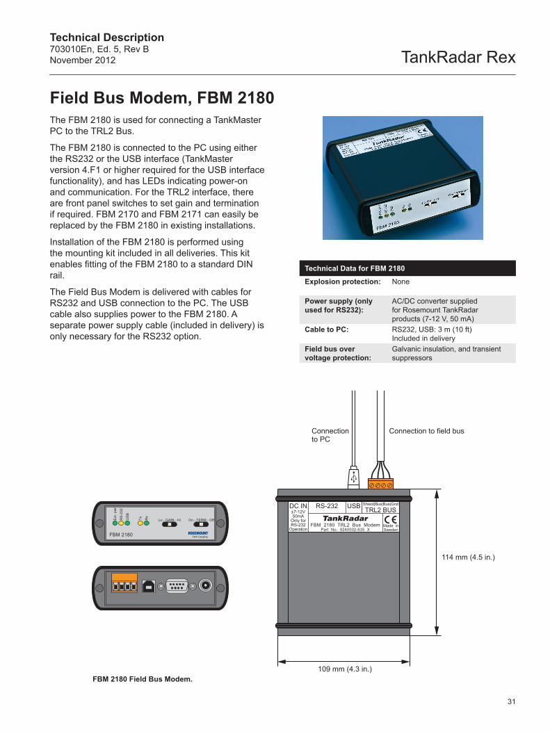
Technical Data for FBM 2180
Explosion protection: None
Power supply (only used for RS232):
AC/DC converter supplied for Rosemount TankRadar products (7-12 V, 50 mA)
Cable to PC: RS232, USB: 3 m (10 ft) Included in delivery
Field bus over voltage protection:
Galvanic insulation, and transient suppressors
FBM 2180
Ext
. pw
r
RS
-232
US
B
Tx Rx
Lo - GAIN - Hi On - TERM - Off
RS-232DC IN±7-12V50mA
Only forRS-232
OperationFBM 2180 TRL2 Bus Modem
Part No. 9240002-635 XMade inSweden
Shield|Bus|Bus|Gnd
TRL2 BUSUSB
Connection to PC
114 mm (4.5 in.)
Connection to field bus
109 mm (4.3 in.)
Field Bus Modem, FBM 2180The FBM 2180 is used for connecting a TankMaster PC to the TRL2 Bus.
The FBM 2180 is connected to the PC using either the RS232 or the USB interface (TankMaster version 4.F1 or higher required for the USB interface functionality), and has LEDs indicating power-on and communication. For the TRL2 interface, there are front panel switches to set gain and termination if required. FBM 2170 and FBM 2171 can easily be replaced by the FBM 2180 in existing installations.
Installation of the FBM 2180 is performed using the mounting kit included in all deliveries. This kit enables fitting of the FBM 2180 to a standard DIN rail.
The Field Bus Modem is delivered with cables for RS232 and USB connection to the PC. The USB cable also supplies power to the FBM 2180. A separate power supply cable (included in delivery) is only necessary for the RS232 option.
FBM 2180 Field Bus Modem.
31
TankRadar RexTechnical Description
703010En, Ed. 5, Rev BNovember 2012
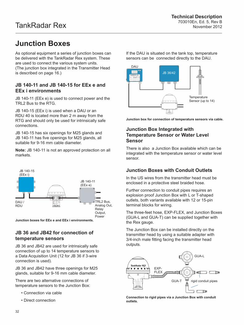
Junction box for connection of temperature sensors via cable.
TRL2 Bus, Analog Out, Relay Output, Power
JB 140-15 (EEx i)
JB 140-11 (EEx e)
DAU / RDU
rigid conduit pipes
Connection to rigid pipes via a Junction Box with conduit outlets.
EXP-FLEX
GUA-L
GUA-T
DAU
Temperature Sensor (up to 14)
JB 36/42
32
Junction boxes for EEx e and EEx i environments.
JB 36 and JB42 for connection of temperature sensorsJB 36 and JB42 are used for intrinsically safe connection of up to 14 temperature sensors to a Data Acquisition Unit (12 for JB 36 if 3-wire connection is used).
JB 36 and JB42 have three openings for M25 glands, suitable for 9-16 mm cable diameter.
There are two alternative connections of temperature sensors to the Junction Box:
• Connection via cable
• Direct connection
As optional equipment a series of junction boxes can be delivered with the TankRadar Rex system. These are used to connect the various system units. (The junction box integrated in the Transmitter Head is described on page 16.)
JB 140-11 and JB 140-15 for EEx e and EEx i environmentsJB 140-11 (EEx e) is used to connect power and the TRL2 Bus to the RTG.
JB 140-15 (EEx i) is used when a DAU or an RDU 40 is located more than 2 m away from the RTG and should only be used for intrinsically safe connections.
JB 140-15 has six openings for M25 glands and JB 140-11 has five openings for M25 glands, all suitable for 9-16 mm cable diameter.
Note: JB 140-11 is not an approved protection on all markets.
If the DAU is situated on the tank top, temperature sensors can be connected directly to the DAU.
Junction Box Integrated with Temperature Sensor or Water Level SensorThere is also a Junction Box available which can be integrated with the temperature sensor or water level sensor.
Junction Boxes with Conduit OutletsIn the US wires from the transmitter head must be enclosed in a protective steel braided hose.
Further connection to conduit pipes requires an explosion proof Junction Box with L or T-shaped outlets, both variants available with 12 or 15-pin terminal blocks for wiring.
The three-feet hose, EXP-FLEX, and Junction Boxes (GUA-L and GUA-T) can be supplied together with the Rex gauge.
The Junction Box can be installed directly on the transmitter head by using a suitable adapter with 3/4-inch male fitting facing the transmitter head outputs.
Junction Boxes
Technical Description703010En, Ed. 5, Rev BNovember 2012 TankRadar Rex
SCADA Engineering Management
Modbus
Modbus
TankMasterOPC Server TankMaster
OPC Server
TRL2 Field Bus Tank Data, Level, Temperature, Pressure, Volume etc
Modbus
DCS
PLC
OPC Client Ethernet
FCU
33
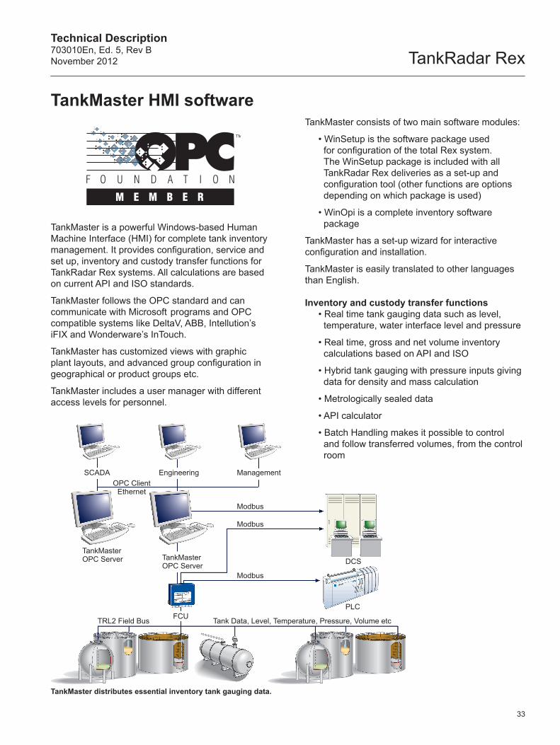
TankMaster distributes essential inventory tank gauging data.
TankMaster is a powerful Windows-based Human Machine Interface (HMI) for complete tank inventory management. It provides configuration, service and set up, inventory and custody transfer functions for TankRadar Rex systems. All calculations are based on current API and ISO standards.
TankMaster follows the OPC standard and can communicate with Microsoft programs and OPC compatible systems like DeltaV, ABB, Intellution’s iFIX and Wonderware’s InTouch.
TankMaster has customized views with graphic plant layouts, and advanced group configuration in geographical or product groups etc.
TankMaster includes a user manager with different access levels for personnel.
TankMaster consists of two main software modules:
• WinSetup is the software package used for configuration of the total Rex system. The WinSetup package is included with all TankRadar Rex deliveries as a set-up and configuration tool (other functions are options depending on which package is used)
• WinOpi is a complete inventory software package
TankMaster has a set-up wizard for interactive configuration and installation.
TankMaster is easily translated to other languages than English.
Inventory and custody transfer functions• Real time tank gauging data such as level,
temperature, water interface level and pressure
• Real time, gross and net volume inventory calculations based on API and ISO
• Hybrid tank gauging with pressure inputs giving data for density and mass calculation
• Metrologically sealed data
• API calculator
• Batch Handling makes it possible to control and follow transferred volumes, from the control room
TankMaster HMI software
TankRadar RexTechnical Description
703010En, Ed. 5, Rev BNovember 2012
34
Reports and data sampling• Batch report for internal and external transfers.
• Customized Reports to Microsoft Office programs
• Automatic reports
• Reports via e-mail
• Audit log for events
• Historical data sampling
Alarms• Reliable alarm handling of measured values
with high, high-high, low and low-low level alarms
• Alarms to mobile phones
• Alarms via e-mail
• Leakage alarms based on net volume
EmulationTankMaster supports a wide range of protocols for gauge and control room emulation. See pages 15, 45 and 48.
TankMaster hydrostatic tank gaugingThe TankMaster HTG system is an intelligent direct mass measuring system which uses product hydrostatic pressure measurement to derive both the specific gravity and liquid level. See TankMaster HTG Technical Description for more information.
Networking and interfacing• OPC server with browser for easy interface
with other plant computer systems
• Full network capabilities
• SCADA / DCS communication via MODBUS
• SCADA / DCS communication via OPC
• Integration with other tank gauging systems by taking in and displaying data from other vendors’ gauges
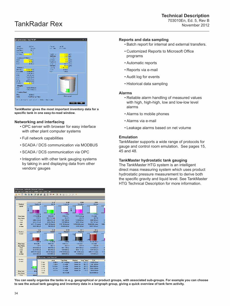
TankMaster gives the most important inventory data for a specific tank in one easy-to-read window.
You can easily organize the tanks in e.g. geographical or product groups, with associated sub-groups. For example you can choose to see the actual tank gauging and inventory data in a bargraph group, giving a quick overview of tank farm activity.
Technical Description703010En, Ed. 5, Rev BNovember 2012 TankRadar Rex
35
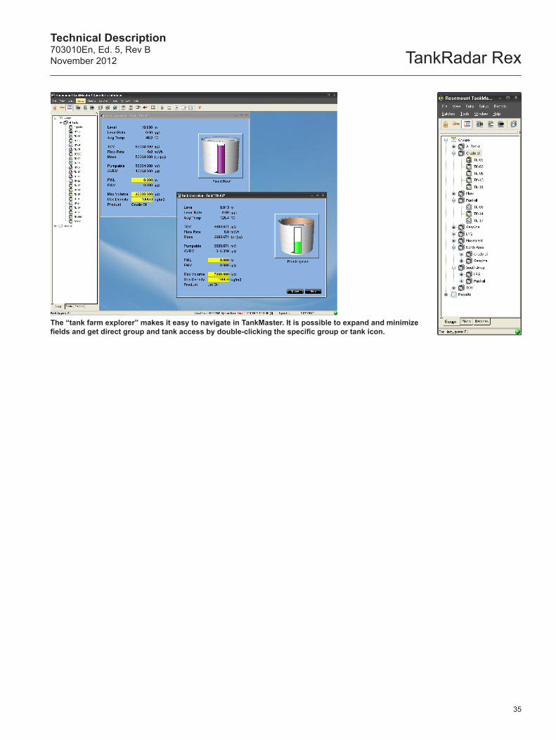
The “tank farm explorer” makes it easy to navigate in TankMaster. It is possible to expand and minimize fields and get direct group and tank access by double-clicking the specific group or tank icon.
TankRadar RexTechnical Description
703010En, Ed. 5, Rev BNovember 2012
36
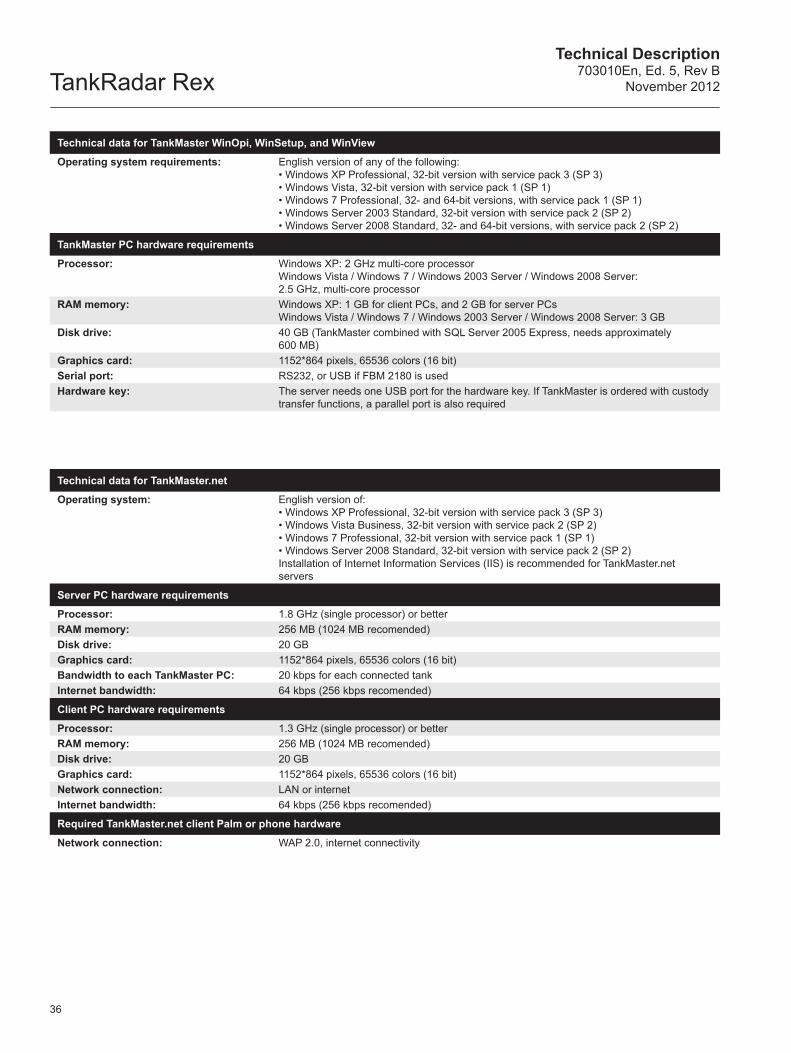
Technical data for TankMaster WinOpi, WinSetup, and WinView
Operating system requirements: English version of any of the following:• Windows XP Professional, 32-bit version with service pack 3 (SP 3)• Windows Vista, 32-bit version with service pack 1 (SP 1)• Windows 7 Professional, 32- and 64-bit versions, with service pack 1 (SP 1)• Windows Server 2003 Standard, 32-bit version with service pack 2 (SP 2)• Windows Server 2008 Standard, 32- and 64-bit versions, with service pack 2 (SP 2)
TankMaster PC hardware requirements
Processor: Windows XP: 2 GHz multi-core processorWindows Vista / Windows 7 / Windows 2003 Server / Windows 2008 Server: 2.5 GHz, multi-core processor
RAM memory: Windows XP: 1 GB for client PCs, and 2 GB for server PCsWindows Vista / Windows 7 / Windows 2003 Server / Windows 2008 Server: 3 GB
Disk drive: 40 GB (TankMaster combined with SQL Server 2005 Express, needs approximately 600 MB)
Graphics card: 1152*864 pixels, 65536 colors (16 bit)Serial port: RS232, or USB if FBM 2180 is usedHardware key: The server needs one USB port for the hardware key. If TankMaster is ordered with custody
transfer functions, a parallel port is also required
Technical data for TankMaster.net
Operating system: English version of:• Windows XP Professional, 32-bit version with service pack 3 (SP 3)• Windows Vista Business, 32-bit version with service pack 2 (SP 2)• Windows 7 Professional, 32-bit version with service pack 1 (SP 1)• Windows Server 2008 Standard, 32-bit version with service pack 2 (SP 2)Installation of Internet Information Services (IIS) is recommended for TankMaster.net servers
Server PC hardware requirements
Processor: 1.8 GHz (single processor) or betterRAM memory: 256 MB (1024 MB recomended)Disk drive: 20 GBGraphics card: 1152*864 pixels, 65536 colors (16 bit)Bandwidth to each TankMaster PC: 20 kbps for each connected tankInternet bandwidth: 64 kbps (256 kbps recomended)
Client PC hardware requirements
Processor: 1.3 GHz (single processor) or betterRAM memory: 256 MB (1024 MB recomended)Disk drive: 20 GBGraphics card: 1152*864 pixels, 65536 colors (16 bit)Network connection: LAN or internetInternet bandwidth: 64 kbps (256 kbps recomended)
Required TankMaster.net client Palm or phone hardware
Network connection: WAP 2.0, internet connectivity
Technical Description703010En, Ed. 5, Rev BNovember 2012 TankRadar Rex
TankMaster
IOT5110
IOT5130
IOT5120
IOT5140
37
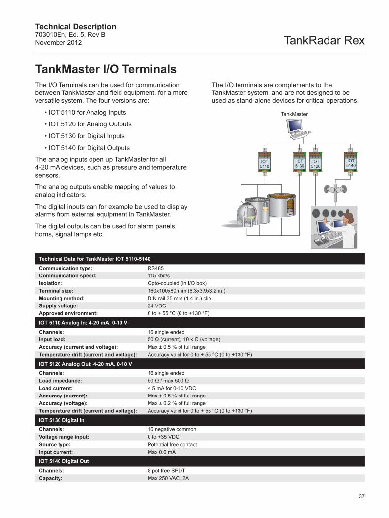
TankMaster I/O TerminalsThe I/O Terminals can be used for communication between TankMaster and field equipment, for a more versatile system. The four versions are:
• IOT 5110 for Analog Inputs
• IOT 5120 for Analog Outputs
• IOT 5130 for Digital Inputs
• IOT 5140 for Digital Outputs
The analog inputs open up TankMaster for all 4-20 mA devices, such as pressure and temperature sensors.
The analog outputs enable mapping of values to analog indicators.
The digital inputs can for example be used to display alarms from external equipment in TankMaster.
The digital outputs can be used for alarm panels, horns, signal lamps etc.
Technical Data for TankMaster IOT 5110-5140
Communication type: RS485Communication speed: 115 kbit/sIsolation: Opto-coupled (in I/O box)Terminal size: 160x100x80 mm (6.3x3.9x3.2 in.)Mounting method: DIN rail 35 mm (1.4 in.) clipSupply voltage: 24 VDC Approved environment: 0 to + 55 °C (0 to +130 °F)
IOT 5110 Analog In; 4-20 mA, 0-10 V
Channels: 16 single endedInput load: 50 Ω (current), 10 k Ω (voltage)Accuracy (current and voltage): Max ± 0.5 % of full rangeTemperature drift (current and voltage): Accuracy valid for 0 to + 55 °C (0 to +130 °F)
IOT 5120 Analog Out; 4-20 mA, 0-10 V
Channels: 16 single endedLoad impedance: 50 Ω / max 500 Ω Load current: < 5 mA for 0-10 VDCAccuracy (current): Max ± 0.5 % of full rangeAccuracy (voltage): Max ± 0.2 % of full rangeTemperature drift (current and voltage): Accuracy valid for 0 to + 55 °C (0 to +130 °F)
IOT 5130 Digital In
Channels: 16 negative commonVoltage range input: 0 to +35 VDCSource type: Potential free contactInput current: Max 0.6 mA
IOT 5140 Digital Out
Channels: 8 pot free SPDTCapacity: Max 250 VAC, 2A
The I/O terminals are complements to the TankMaster system, and are not designed to be used as stand-alone devices for critical operations.
TankRadar RexTechnical Description
703010En, Ed. 5, Rev BNovember 2012
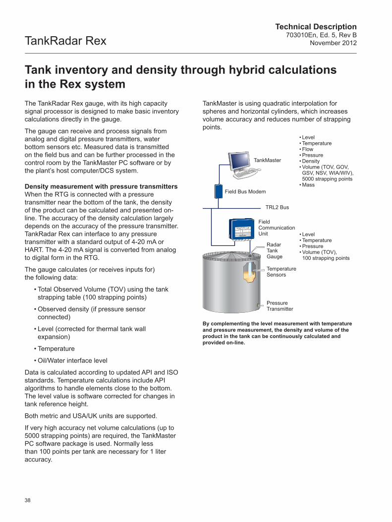
The TankRadar Rex gauge, with its high capacity signal processor is designed to make basic inventory calculations directly in the gauge.
The gauge can receive and process signals from analog and digital pressure transmitters, water bottom sensors etc. Measured data is transmitted on the field bus and can be further processed in the control room by the TankMaster PC software or by the plant’s host computer/DCS system.
Density measurement with pressure transmitters When the RTG is connected with a pressure transmitter near the bottom of the tank, the density of the product can be calculated and presented on-line. The accuracy of the density calculation largely depends on the accuracy of the pressure transmitter. TankRadar Rex can interface to any pressure transmitter with a standard output of 4-20 mA or HART. The 4-20 mA signal is converted from analog to digital form in the RTG.
The gauge calculates (or receives inputs for) the following data:
• Total Observed Volume (TOV) using the tank strapping table (100 strapping points)
• Observed density (if pressure sensor connected)
• Level (corrected for thermal tank wall expansion)
• Temperature
• Oil/Water interface level
Data is calculated according to updated API and ISO standards. Temperature calculations include API algorithms to handle elements close to the bottom.The level value is software corrected for changes in tank reference height.
Both metric and USA/UK units are supported.
If very high accuracy net volume calculations (up to 5000 strapping points) are required, the TankMaster PC software package is used. Normally less than 100 points per tank are necessary for 1 liter accuracy.
Tank inventory and density through hybrid calculations in the Rex system
By complementing the level measurement with temperature and pressure measurement, the density and volume of the product in the tank can be continuously calculated and provided on-line.
TankMaster is using quadratic interpolation for spheres and horizontal cylinders, which increases volume accuracy and reduces number of strapping points.
RadarTankGauge
TemperatureSensors
PressureTransmitter
FieldCommunicationUnit
Field Bus Modem
TankMaster
TRL2 Bus
• Level• Temperature• Flow• Pressure• Density• Volume (TOV, GOV, GSV, NSV, WIA/WIV), 5000 strapping points
• Mass
• Level• Temperature• Pressure• Volume (TOV), 100 strapping points
38
Technical Description703010En, Ed. 5, Rev BNovember 2012 TankRadar Rex
TRL2 Group Bus
TRL2 Field Bus
Up to four TRL2 Field Buses from each FCU
Up to 8 units on each TRL2 Bus
Up to 8units oneach TRL2 Bus
RTG RTG RTG RTG RTG RTG
FCU FCU FCU FCU FCU FCU
TM orDCS
FBM FBM
TM orDCS
39
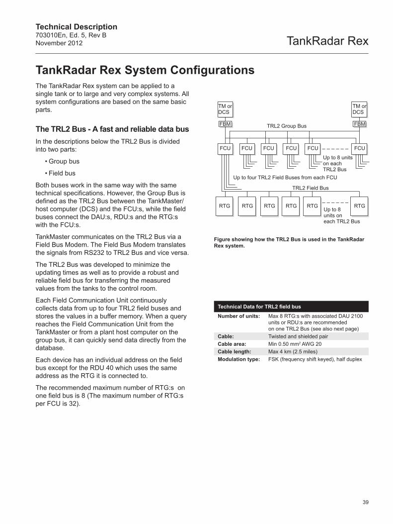
The TankRadar Rex system can be applied to a single tank or to large and very complex systems. All system configurations are based on the same basic parts.
The TRL2 Bus - A fast and reliable data busIn the descriptions below the TRL2 Bus is divided into two parts:
• Group bus
• Field bus
Both buses work in the same way with the same technical specifications. However, the Group Bus is defined as the TRL2 Bus between the TankMaster/host computer (DCS) and the FCU:s, while the field buses connect the DAU:s, RDU:s and the RTG:s with the FCU:s.
TankMaster communicates on the TRL2 Bus via a Field Bus Modem. The Field Bus Modem translates the signals from RS232 to TRL2 Bus and vice versa.
The TRL2 Bus was developed to minimize the updating times as well as to provide a robust and reliable field bus for transferring the measured values from the tanks to the control room.
Each Field Communication Unit continuously collects data from up to four TRL2 field buses and stores the values in a buffer memory. When a query reaches the Field Communication Unit from the TankMaster or from a plant host computer on the group bus, it can quickly send data directly from the database.
Each device has an individual address on the field bus except for the RDU 40 which uses the same address as the RTG it is connected to.
The recommended maximum number of RTG:s on one field bus is 8 (The maximum number of RTG:s per FCU is 32).
TankRadar Rex System Configurations
Figure showing how the TRL2 Bus is used in the TankRadar Rex system.
Technical Data for TRL2 field bus
Number of units: Max 8 RTG:s with associated DAU 2100 units or RDU:s are recommended on one TRL2 Bus (see also next page)
Cable: Twisted and shielded pairCable area: Min 0.50 mm2 AWG 20Cable length: Max 4 km (2.5 miles)Modulation type: FSK (frequency shift keyed), half duplex
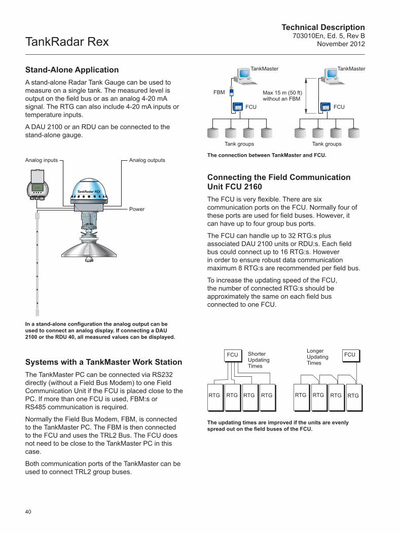
TankRadar RexTechnical Description
703010En, Ed. 5, Rev BNovember 2012
FCU FCUShorter Updating Times
Longer Updating Times
RTG RTG RTG RTG RTG RTG RTG RTG
Analog inputs Analog outputs
Power
TankMaster TankMaster
FCU FCU
Tank groups Tank groups
FBM Max 15 m (50 ft) without an FBM
40
In a stand-alone configuration the analog output can be used to connect an analog display. If connecting a DAU 2100 or the RDU 40, all measured values can be displayed.
Stand-Alone ApplicationA stand-alone Radar Tank Gauge can be used to measure on a single tank. The measured level is output on the field bus or as an analog 4-20 mA signal. The RTG can also include 4-20 mA inputs or temperature inputs.
A DAU 2100 or an RDU can be connected to the stand-alone gauge.
The updating times are improved if the units are evenly spread out on the field buses of the FCU.
The connection between TankMaster and FCU.
Systems with a TankMaster Work StationThe TankMaster PC can be connected via RS232 directly (without a Field Bus Modem) to one Field Communication Unit if the FCU is placed close to the PC. If more than one FCU is used, FBM:s or RS485 communication is required.
Normally the Field Bus Modem, FBM, is connected to the TankMaster PC. The FBM is then connected to the FCU and uses the TRL2 Bus. The FCU does not need to be close to the TankMaster PC in this case.
Both communication ports of the TankMaster can be used to connect TRL2 group buses.
Connecting the Field Communication Unit FCU 2160The FCU is very flexible. There are six communication ports on the FCU. Normally four of these ports are used for field buses. However, it can have up to four group bus ports.
The FCU can handle up to 32 RTG:s plus associated DAU 2100 units or RDU:s. Each field bus could connect up to 16 RTG:s. However in order to ensure robust data communication maximum 8 RTG:s are recommended per field bus.
To increase the updating speed of the FCU, the number of connected RTG:s should be approximately the same on each field bus connected to one FCU.
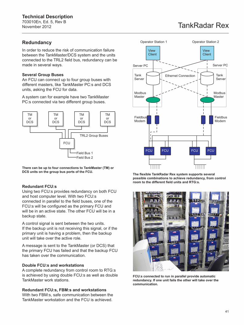
Technical Description703010En, Ed. 5, Rev BNovember 2012 TankRadar Rex
Operator Station 1 Operator Station 2
View Client
View Client
Server PC Server PC
Tank Server
Tank Server
Modbus Master
Modbus Master
Fieldbus Modem
Fieldbus Modem
FCU FCU FCU FCU
Ethernet Connection
TMor
DCS
TMor
DCS
TMor
DCS
TMor
DCS
TRL2 Group Buses
Field Bus 1Field Bus 2
FCU
41
Redundant FCU:sUsing two FCU:s provides redundancy on both FCU and host computer level. With two FCU:s connected in parallel to the field buses, one of the FCU:s will be configured as the primary FCU and will be in an active state. The other FCU will be in a backup state.
A control signal is sent between the two units. If the backup unit is not receiving this signal, or if the primary unit is having a problem, then the backup unit will take over the active role.
A message is sent to the TankMaster (or DCS) that the primary FCU has failed and that the backup FCU has taken over the communication.
Double FCU:s and workstationsA complete redundancy from control room to RTG:s is achieved by using double FCU:s as well as double TankMaster work stations.
Redundant FCU:s, FBM:s and workstationsWith two FBM:s, safe communication between the TankMaster workstation and the FCU is achieved.
RedundancyIn order to reduce the risk of communication failure between the TankMaster/DCS system and the units connected to the TRL2 field bus, redundancy can be made in several ways.
Several Group BusesAn FCU can connect up to four group buses with different masters, like TankMaster PC:s and DCS units, asking the FCU for data.
A system can for example have two TankMaster PC:s connected via two different group buses.
The flexible TankRadar Rex system supports several possible combinations to achieve redundancy, from control room to the different field units and RTG:s.
FCU:s connected to run in parallel provide automatic redundancy. If one unit fails the other will take over the communication.
There can be up to four connections to TankMaster (TM) or DCS units on the group bus ports of the FCU.
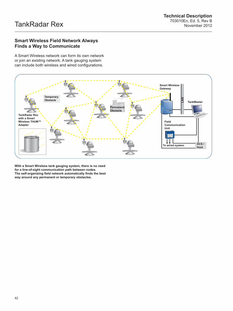
TankRadar RexTechnical Description
703010En, Ed. 5, Rev BNovember 2012
42
With a Smart Wireless tank gauging system, there is no need for a line-of-sight communication path between nodes. The self-organizing field network automatically finds the best way around any permanent or temporary obstacles.
Smart Wireless Field Network Always Finds a Way to Communicate
A Smart Wireless network can form its own network or join an existing network. A tank gauging system can include both wireless and wired configurations.
Temporary Obstacle
Permanent Obstacle
TankRadar Rex with a Smart Wireless THUM™ Adapter
Smart Wireless Gateway
Field Communication Unit
To wired system
TankMaster
DCS / Host
LAN
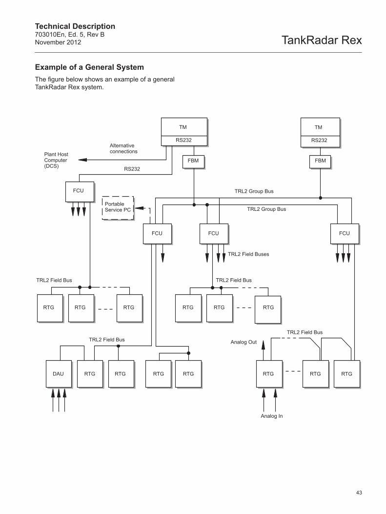
Technical Description703010En, Ed. 5, Rev BNovember 2012 TankRadar Rex
Alternative connectionsPlant Host
Computer (DCS)
TM
RS232
FBM
FCU
FCU FCU
TM
RS232
FBM
FCU
TRL2 Group Bus
TRL2 Group Bus
TRL2 Field Bus TRL2 Field Bus
TRL2 Field BusTRL2 Field Bus
TRL2 Field Buses
Analog Out
Analog In
RTG RTG RTG RTG RTG RTG
RTG RTG RTG RTG RTGRTGRTGDAU
RS232
Portable Service PC
43
Example of a General System The figure below shows an example of a general TankRadar Rex system.
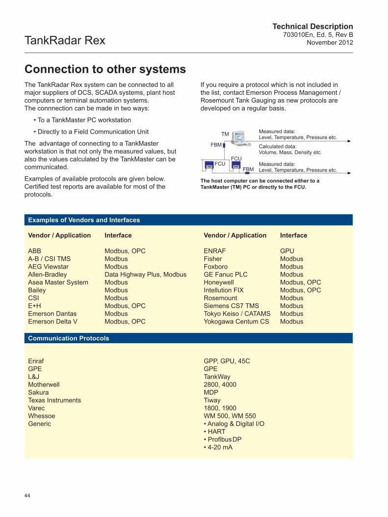
TankRadar RexTechnical Description
703010En, Ed. 5, Rev BNovember 2012
The TankRadar Rex system can be connected to all major suppliers of DCS, SCADA systems, plant host computers or terminal automation systems. The connnection can be made in two ways:
• To a TankMaster PC workstation
• Directly to a Field Communication Unit
The advantage of connecting to a TankMaster workstation is that not only the measured values, but also the values calculated by the TankMaster can be communicated.
Examples of available protocols are given below. Certified test reports are available for most of the protocols.
Connection to other systemsIf you require a protocol which is not included in the list, contact Emerson Process Management / Rosemount Tank Gauging as new protocols are developed on a regular basis.
The host computer can be connected either to a TankMaster (TM) PC or directly to the FCU.
FCUFCU
FBM
FBM
TM Measured data: Level, Temperature, Pressure etc.
Measured data: Level, Temperature, Pressure etc.
Calculated data: Volume, Mass, Density etc.
44
Examples of Vendors and Interfaces
Vendor / Application
ABBA-B / CSI TMSAEG ViewstarAllen-BradleyAsea Master SystemBaileyCSIE+HEmerson DantasEmerson Delta V
Interface
Modbus, OPCModbusModbusData Highway Plus, ModbusModbusModbusModbusModbus, OPCModbusModbus, OPC
Vendor / Application
ENRAFFisherFoxboro
GE Fanuc PLCHoneywellIntellution FIXRosemountSiemens CS7 TMSTokyo Keiso / CATAMSYokogawa Centum CS
Interface
GPUModbusModbus ModbusModbus, OPCModbus, OPCModbusModbusModbusModbus
Communication Protocols
Enraf GPE L&J Motherwell Sakura Texas Instruments Varec Whessoe Generic
GPP, GPU, 45CGPETankWay2800, 4000MDPTiway1800, 1900WM 500, WM 550• Analog & Digital I/O• HART• Profibus DP• 4-20 mA
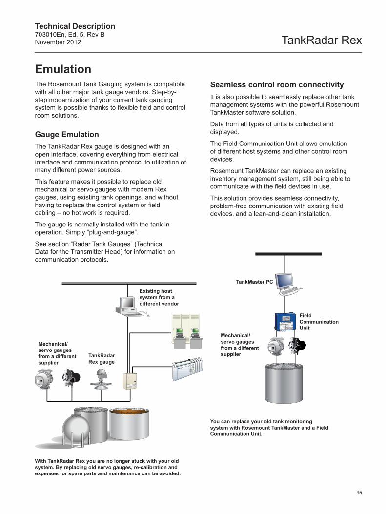
Technical Description703010En, Ed. 5, Rev BNovember 2012 TankRadar Rex
EmulationThe Rosemount Tank Gauging system is compatible with all other major tank gauge vendors. Step-by-step modernization of your current tank gauging system is possible thanks to flexible field and control room solutions.
Gauge EmulationThe TankRadar Rex gauge is designed with an open interface, covering everything from electrical interface and communication protocol to utilization of many different power sources.
This feature makes it possible to replace old mechanical or servo gauges with modern Rex gauges, using existing tank openings, and without having to replace the control system or field cabling – no hot work is required.
The gauge is normally installed with the tank in operation. Simply “plug-and-gauge”.
See section “Radar Tank Gauges” (Technical Data for the Transmitter Head) for information on communication protocols.
Seamless control room connectivityIt is also possible to seamlessly replace other tank management systems with the powerful Rosemount TankMaster software solution.
Data from all types of units is collected and displayed.
The Field Communication Unit allows emulation of different host systems and other control room devices.
Rosemount TankMaster can replace an existing inventory management system, still being able to communicate with the field devices in use.
This solution provides seamless connectivity, problem-free communication with existing field devices, and a lean-and-clean installation.
With TankRadar Rex you are no longer stuck with your old system. By replacing old servo gauges, re-calibration and expenses for spare parts and maintenance can be avoided.
CIU858
TankRadar Rex gauge
You can replace your old tank monitoring system with Rosemount TankMaster and a Field Communication Unit.
TankMaster PC
Field Communication Unit
Mechanical/servo gauges from a different supplier
Mechanical/servo gauges from a different supplier
Existing host system from a different vendor
45
TankRadar RexTechnical Description
703010En, Ed. 5, Rev BNovember 2012
46
The list below includes certificates and approvals for the TankRadar Rex system. It does not give any detailed information on each certificate or approval.
There may be restrictions such that a certificate may be valid for only parts of the system.
Contact Emerson Process Management / Rosemount Tank Gauging if you require more information on any of the certificates.
Accuracy approvals / Legal metrological certificates
• International: OIML R85 (E)
• Germany: PTB
• France: LNE
• Italy: Metric office
• Portugal: IPQ
• The Netherlands: NMI
• Belgium: BMS
• Austria: BEV
• Switzerland: METAS
• Hungary: OMH
• Czech Republic: CMI
• Croatia: DZM
• Serbia/Montenegro: FBMPM
• Romania: BRML
• Poland: GUM
• Estonia: TJI
• Russia, Belarus, Ukraine, Kazachstan: GOST Standard
• Algeria: ONML
• China: CMI
• India: W&M
• Indonesia: MIGAS
• Malaysia: SIRIM
• Thailand: Thai Excise and Customs
• Bosnia and Herzegovina: MI
• Bulgaria: Measuring Instrument Type Approval Certificate
CertificatesIn addition to the listed accuracy approvals, many countries are presently in the process to define custody transfer requirements.
EX Approvals• EU: ATEX directive
• International: IEC Ex
• USA: UL
• Canada: C-UL
• Brazil: CEPEL
• Russia, Belarus, Ukraine, Kazachstan: GOST Standard
• China: CNACL
• Korea: KOSHA
• Japan: JIS
• India: Nagpur
• TÜV, Austria
Safety Approvals and Acknowledgements
• SIL 2 suitable
• Belgium: Vlarem II
• Germany: WHG approval for overfill prevention, tested by TÜV
Emission ApprovalsThe listed approvals below deal with how much radiated power that is sent out from the radar gauge.
In most countries there are no formulated requirements on equipment like a radar gauge, due to the very low output power and the fact that it is normally installed in a metallic tank.
TankRadar gauges have been tested in accordance with CISPR-22 and CISPR-16.
Technical Description703010En, Ed. 5, Rev BNovember 2012 TankRadar Rex
47
The certificates listed below are exceptions for specific countries:
• Bundes Ministerium für Post und Telekommunikationen, BMPT, Germany
• Federal Communications Commission, FCC, USA
• Post und Telegraf Direktion, Austria
• Department of Trade and Industry / Radio Communication Agency DTI / RCA, United Kingdom
Miscellaneous Approvals• SIL 2 Safety Functions
• CE Mark, European Community
• TÜV Overfilling Protection, Germany
• TÜV Pressure Approval, Germany
• TÜV Firesafe Approval, Germany
In addition to the list above, there are a number of certificates or approvals for optional equipment which can be delivered.
Junction boxes, pressure transducers, water interface sensors, etc. have approvals in the name of their manufacturers. Copies of these can be requested from Emerson Process Management / Rosemount Tank Gauging.
Vapor Influence on Radar MeasurementFor a few specific products there can be a measurable influence on the level accuracy, if the composition of the vapor varies between no vapor and fully saturated vapor condition. However, there is no noticeable influence, if the vapor variation is small.
For these specific products it is in many cases sufficient that the pressure and temperature is measured. The software in the Radar Tank Gauge then automatically corrects for the influence from
the vapor. This is for example performed when measuring in LPG tanks.
Gases that are known to affect the transmission of radar waves are:
• Propylene oxide
• Etylether
• Propylether
• Acetaldehyde
• Propionaldehyde
• Isobutyraldehyde
• Acetone
• 2-Butanone
• Methanol
One gas that dampens (or attenuates) the radar signal is ammonia. In applications where ammonia is involved, Emerson Process Management / Rosemount Tank Gauging should always be contacted for evaluation of the application.
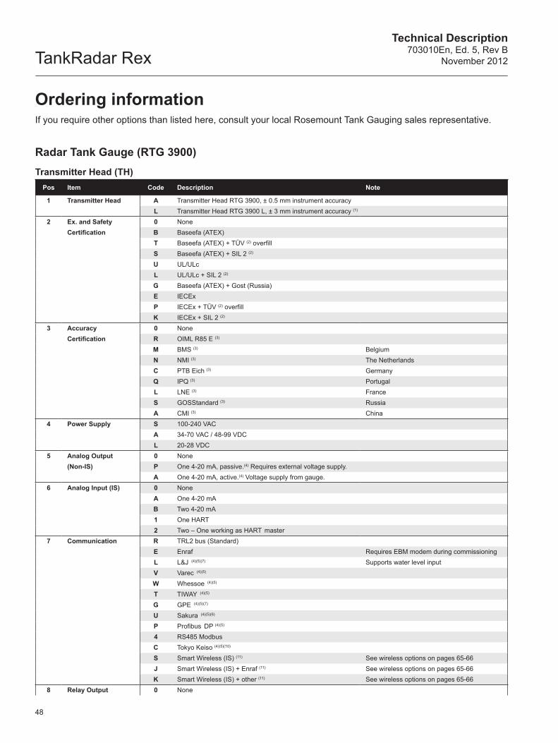
TankRadar RexTechnical Description
703010En, Ed. 5, Rev BNovember 2012
48
Radar Tank Gauge (RTG 3900)Transmitter Head (TH)
Pos Item Code Description Note
1 Transmitter Head A Transmitter Head RTG 3900, ± 0.5 mm instrument accuracyL Transmitter Head RTG 3900 L, ± 3 mm instrument accuracy (1)
2 Ex. and Safety 0 NoneCertification B Baseefa (ATEX)
T Baseefa (ATEX) + TÜV (2) overfillS Baseefa (ATEX) + SIL 2 (2)
U UL/ULc L UL/ULc + SIL 2 (2)
G Baseefa (ATEX) + Gost (Russia)E IECExP IECEx + TÜV (2) overfillK IECEx + SIL 2 (2)
3 Accuracy 0 NoneCertification R OIML R85 E (3)
M BMS (3) BelgiumN NMI (3) The NetherlandsC PTB Eich (3) GermanyQ IPQ (3) PortugalL LNE (3) FranceS GOSStandard (3) RussiaA CMI (3) China
4 Power Supply S 100-240 VACA 34-70 VAC / 48-99 VDCL 20-28 VDC
5 Analog Output 0 None(Non-IS) P One 4-20 mA, passive.(4) Requires external voltage supply.
A One 4-20 mA, active.(4) Voltage supply from gauge.6 Analog Input (IS) 0 None
A One 4-20 mAB Two 4-20 mA 1 One HART 2 Two – One working as HART master
7 Communication R TRL2 bus (Standard)E Enraf Requires EBM modem during commissioningL L&J (4)(5)(7) Supports water level inputV Varec (4)(5)
W Whessoe (4)(5)
T TIWAY (4)(5)
G GPE (4)(5)(7)
U Sakura (4)(5)(6)
P Profibus DP (4)(5)
4 RS485 ModbusC Tokyo Keiso (4)(5)(10)
S Smart Wireless (IS) (11) See wireless options on pages 65-66J Smart Wireless (IS) + Enraf (11) See wireless options on pages 65-66K Smart Wireless (IS) + other (11) See wireless options on pages 65-66
8 Relay Output 0 None
Ordering informationIf you require other options than listed here, consult your local Rosemount Tank Gauging sales representative.
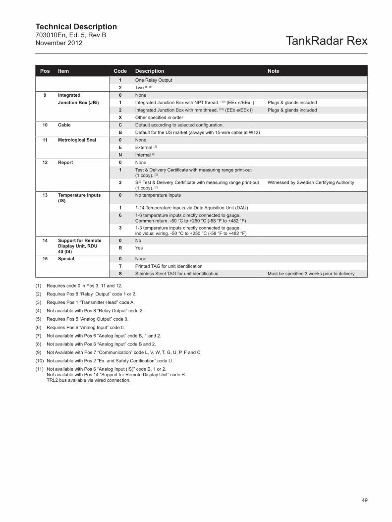
Technical Description703010En, Ed. 5, Rev BNovember 2012 TankRadar Rex
49
Pos Item Code Description Note1 One Relay Output2 Two (5) (9)
9 Integrated 0 NoneJunction Box (JBi) 1 Integrated Junction Box with NPT thread. (10) (EEx e/EEx i) Plugs & glands included
2 Integrated Junction Box with mm thread. (10) (EEx e/EEx i) Plugs & glands includedX Other specified in order
10 Cable C Default according to selected configuration.B Default for the US market (always with 15-wire cable at W12)
11 Metrological Seal 0 NoneE External (2)
N Internal (2)
12 Report 0 None1 Test & Delivery Certificate with measuring range print-out
(1 copy). (2)
2 SP Test & Delivery Certificate with measuring range print-out (1 copy). (2)
Witnessed by Swedish Certifying Authority
13 Temperature Inputs (IS)
0 No temperature inputs
1 1-14 Temperature inputs via Data Aquisition Unit (DAU)6 1-6 temperature inputs directly connected to gauge.
Common return. -50 °C to +250 °C (-58 °F to +482 °F)3 1-3 temperature inputs directly connected to gauge.
individual wiring. -50 °C to +250 °C (-58 °F to +482 °F)14 Support for Remote
Display Unit, RDU 40 (IS)
0 NoR Yes
15 Special 0 NoneT Printed TAG for unit identificationS Stainless Steel TAG for unit identification Must be specified 3 weeks prior to delivery
(1) Requires code 0 in Pos 3, 11 and 12.
(2) Requires Pos 8 “Relay Output” code 1 or 2.
(3) Requires Pos 1 “Transmitter Head” code A.
(4) Not available with Pos 8 “Relay Output” code 2.
(5) Requires Pos 5 “Analog Output” code 0.
(6) Requires Pos 6 “Analog Input” code 0.
(7) Not available with Pos 6 “Analog Input” code B, 1 and 2.
(8) Not available with Pos 6 “Analog Input” code B and 2.
(9) Not Available with Pos 7 “Communication” code L, V, W, T, G, U, P, F and C.
(10) Not available with Pos 2 “Ex. and Safety Certification” code U.
(11) Not available with Pos 6 “Analog Input (IS)” code B, 1 or 2. Not available with Pos 14 “Support for Remote Display Unit” code R. TRL2 bus available via wired connection.
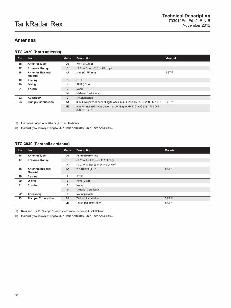
TankRadar RexTechnical Description
703010En, Ed. 5, Rev BNovember 2012
50
Antennas
RTG 3920 (Horn antenna)Pos Item Code Description Material
16 Antenna Type 20 Horn antenna17 Pressure Rating S - 0.2 to 2 bar (-2.9 to 29 psig)18 Antenna Size and
Material1A 8 in. (Ø175 mm) SST (2)
19 Sealing P PTFE20 O-ring V FPM (Viton )21 Special 0 None
M Material Certificate22 Accessory 0 Not applicable23 Flange / Connection 1A 8 in. Hole pattern according to ANSI 8 in. Class 150 / DN 200 PN 10 (1) SST (2)
1B 8 in. 4° Inclined. Hole pattern according to ANSI 8 in. Class 150 / DN 200 PN 10 (1)
(1) Flat faced flange with 13 mm (0.51 in.) thickness.
(2) Material type corresponding to EN 1.4401 / AISI 316, EN 1.4404 / AISI 316L.
RTG 3930 (Parabolic antenna)Pos Item Code Description Material
16 Antenna Type 30 Parabolic antenna17 Pressure Rating S - 0.2 to 0.2 bar (-2.9 to 2.9 psig)
H - 0.2 to 10 bar (2.9 to 145 psig) (1)
18 Antenna Size and Material
1A Ø 440 mm (17 in.) SST (2)
19 Sealing P PTFE20 O-ring V FPM (Viton )21 Special 0 None
M Material Certificate22 Accessory 0 Not applicable23 Flange / Connection 2A Welded installation SST (2)
2B Threaded installation SST (2)
(1) Requires Pos 23 “Flange / Connection” code 2A (welded installation).
(2) Material type corresponding to EN 1.4401 / AISI 316, EN 1.4404 / AISI 316L.
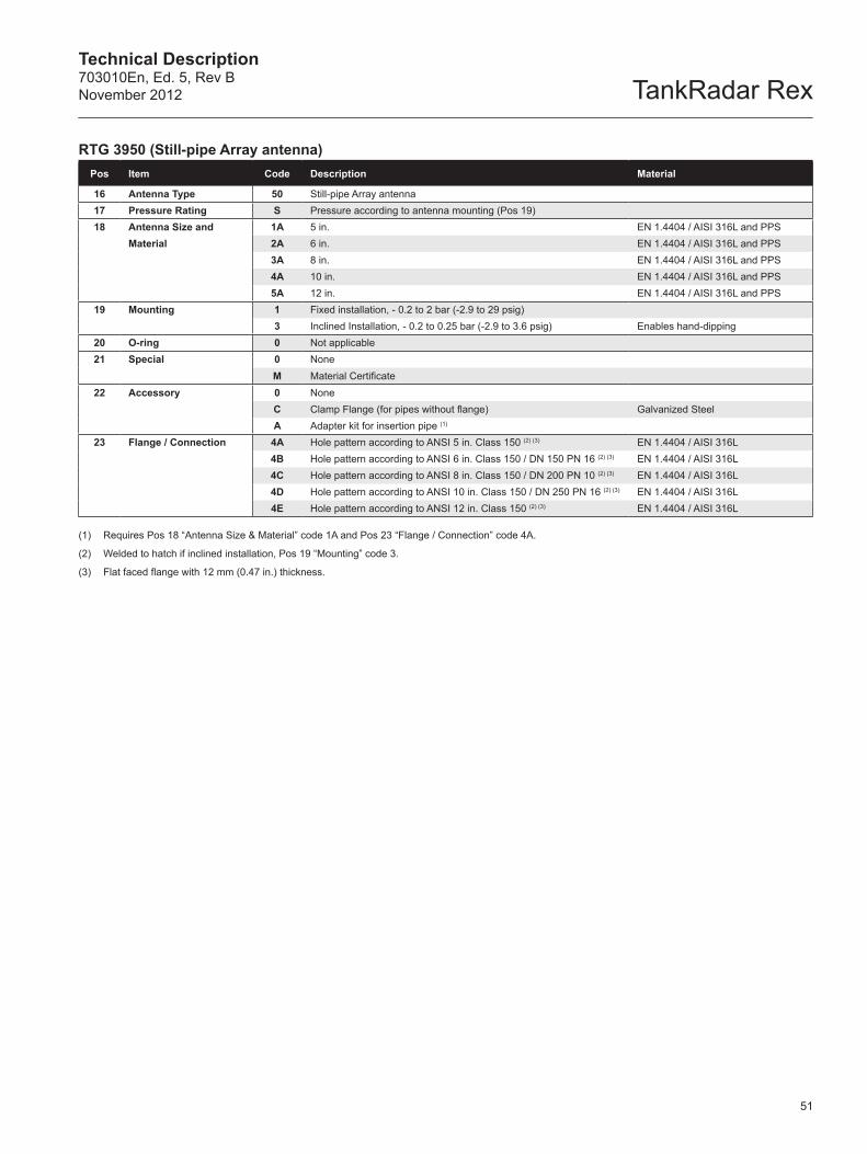
Technical Description703010En, Ed. 5, Rev BNovember 2012 TankRadar Rex
51
RTG 3950 (Still-pipe Array antenna)Pos Item Code Description Material
16 Antenna Type 50 Still-pipe Array antenna17 Pressure Rating S Pressure according to antenna mounting (Pos 19) 18 Antenna Size and 1A 5 in. EN 1.4404 / AISI 316L and PPS
Material 2A 6 in. EN 1.4404 / AISI 316L and PPS3A 8 in. EN 1.4404 / AISI 316L and PPS4A 10 in. EN 1.4404 / AISI 316L and PPS5A 12 in. EN 1.4404 / AISI 316L and PPS
19 Mounting 1 Fixed installation, - 0.2 to 2 bar (-2.9 to 29 psig) 3 Inclined Installation, - 0.2 to 0.25 bar (-2.9 to 3.6 psig) Enables hand-dipping
20 O-ring 0 Not applicable21 Special 0 None
M Material Certificate22 Accessory 0 None
C Clamp Flange (for pipes without flange) Galvanized SteelA Adapter kit for insertion pipe (1)
23 Flange / Connection 4A Hole pattern according to ANSI 5 in. Class 150 (2) (3) EN 1.4404 / AISI 316L4B Hole pattern according to ANSI 6 in. Class 150 / DN 150 PN 16 (2) (3) EN 1.4404 / AISI 316L4C Hole pattern according to ANSI 8 in. Class 150 / DN 200 PN 10 (2) (3) EN 1.4404 / AISI 316L4D Hole pattern according to ANSI 10 in. Class 150 / DN 250 PN 16 (2) (3) EN 1.4404 / AISI 316L4E Hole pattern according to ANSI 12 in. Class 150 (2) (3) EN 1.4404 / AISI 316L
(1) Requires Pos 18 “Antenna Size & Material” code 1A and Pos 23 “Flange / Connection” code 4A.
(2) Welded to hatch if inclined installation, Pos 19 “Mounting” code 3.
(3) Flat faced flange with 12 mm (0.47 in.) thickness.
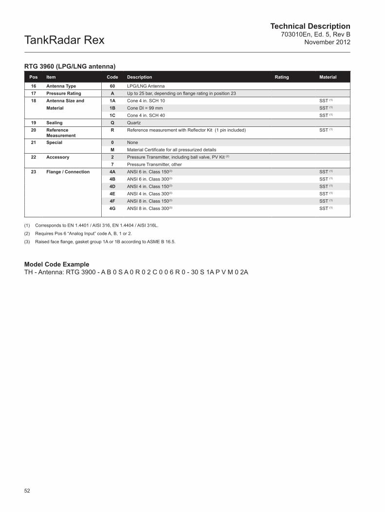
TankRadar RexTechnical Description
703010En, Ed. 5, Rev BNovember 2012
52
RTG 3960 (LPG/LNG antenna)Pos Item Code Description Rating Material
16 Antenna Type 60 LPG/LNG Antenna17 Pressure Rating A Up to 25 bar, depending on flange rating in position 2318 Antenna Size and 1A Cone 4 in. SCH 10 SST (1)
Material 1B Cone DI = 99 mm SST (1)
1C Cone 4 in. SCH 40 SST (1)
19 Sealing Q Quartz20 Reference
MeasurementR Reference measurement with Reflector Kit (1 pin included) SST (1)
21 Special 0 NoneM Material Certificate for all pressurized details
22 Accessory 2 Pressure Transmitter, including ball valve, PV Kit (2)
7 Pressure Transmitter, other23 Flange / Connection 4A ANSI 6 in. Class 150(3) SST (1)
4B ANSI 6 in. Class 300(3) SST (1)
4D ANSI 4 in. Class 150(3) SST (1)
4E ANSI 4 in. Class 300(3) SST (1)
4F ANSI 8 in. Class 150(3) SST (1)
4G ANSI 8 in. Class 300(3) SST (1)
(1) Corresponds to EN 1.4401 / AISI 316, EN 1.4404 / AISI 316L.
(2) Requires Pos 6 “Analog Input” code A, B, 1 or 2.
(3) Raised face flange, gasket group 1A or 1B according to ASME B 16.5.
Model Code ExampleTH - Antenna: RTG 3900 - A B 0 S A 0 R 0 2 C 0 0 6 R 0 - 30 S 1A P V M 0 2A
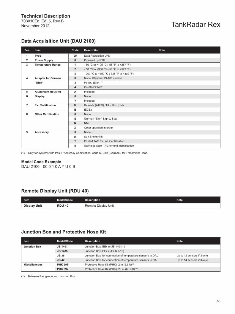
Technical Description703010En, Ed. 5, Rev BNovember 2012 TankRadar Rex
53
Data Acquisition Unit (DAU 2100)
Pos Item Code Description Note
1 Type 00 Data Acquisition Unit2 Power Supply 0 Powered by RTG3 Temperature Range 1 - 50 °C to +125 °C (-58 °F to +257 °F)
2 - 50 °C to +300 °C (-58 °F to +572 °F)3 - 200 °C to +150 °C (-328 °F to +302 °F)
4 Adapter for German 0 None. Standard Pt-100 version.“Eich” 3 Pt-100 (Eich) (1)
4 Cu-90 (Eich) (1)
5 Aluminium Housing A Included6 Display 0 None
Y Included7 Ex. Certification U Baseefa (ATEX) / UL / ULc (Std)
E IECEx8 Other Certification 0 None
S German “Eich” Sign & SealN NMIX Other specified in order
9 Accessory 0 NoneW Sun Shelter KitT Printed TAG for unit identificationS Stainless Steel TAG for unit identification
(1) Only for systems with Pos 3 “Accuracy Certification” code C, Eich (German), for Transmitter Head.
Model Code ExampleDAU 2100 - 00 0 1 0 A Y U 0 S
Remote Display Unit (RDU 40)
Item Model/Code Description Note
Display Unit RDU 40 Remote Display Unit
Junction Box and Protective Hose Kit
Item Model/Code Description Note
Junction Box JB 1401 Junction Box, EEx e (JB 140-11)JB 1405 Junction Box, EEx i (JB 140-15)JB 36 Junction Box, for connection of temperature sensors to DAU Up to 12 sensors if 3-wireJB 42 Junction Box, for connection of temperature sensors to DAU Up to 14 sensors if 3-wire
Miscellaneous PHK 39S Protective Hose Kit (PHK), 2 m (6.6 ft) (1)
PHK 392 Protective Hose Kit (PHK), 20 m (65.6 ft) (1)
(1) Between Rex gauge and Junction Box.
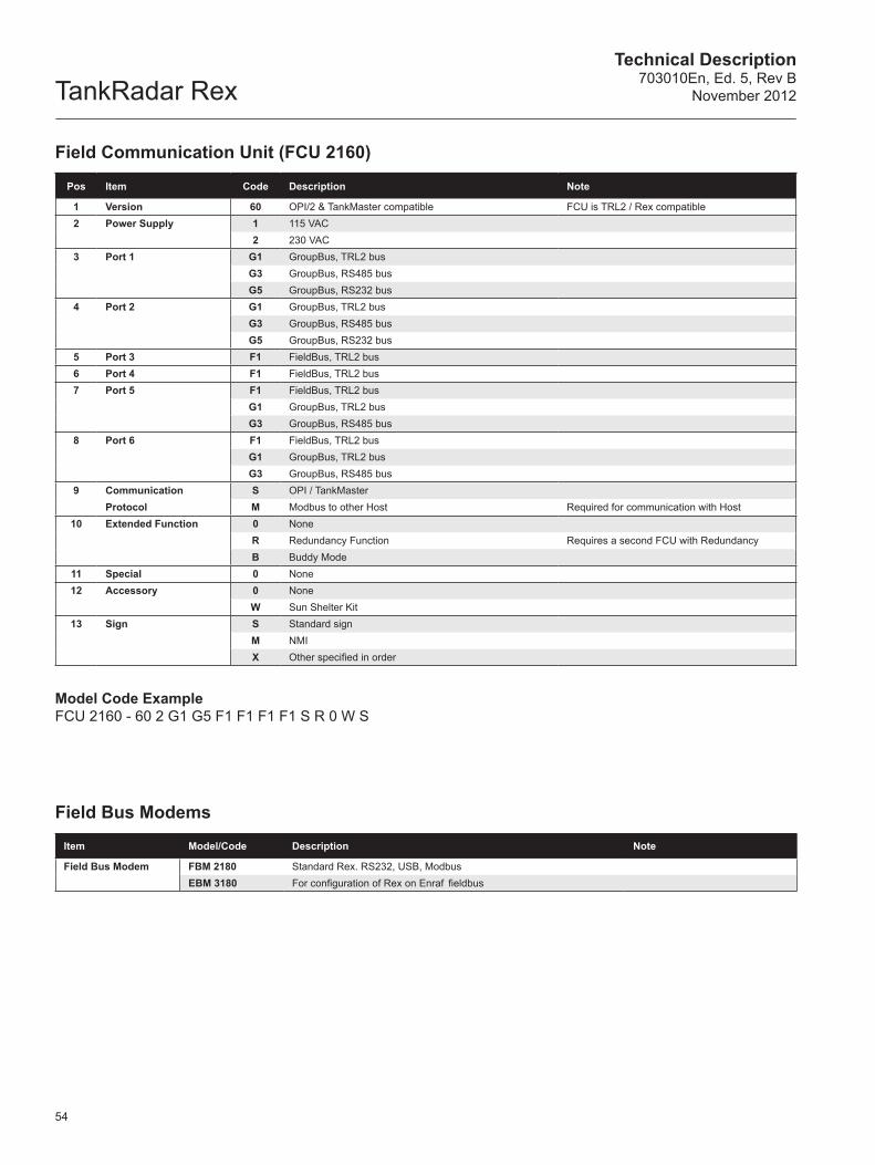
TankRadar RexTechnical Description
703010En, Ed. 5, Rev BNovember 2012
54
Field Communication Unit (FCU 2160)
Pos Item Code Description Note
1 Version 60 OPI/2 & TankMaster compatible FCU is TRL2 / Rex compatible 2 Power Supply 1 115 VAC
2 230 VAC3 Port 1 G1 GroupBus, TRL2 bus
G3 GroupBus, RS485 busG5 GroupBus, RS232 bus
4 Port 2 G1 GroupBus, TRL2 busG3 GroupBus, RS485 busG5 GroupBus, RS232 bus
5 Port 3 F1 FieldBus, TRL2 bus6 Port 4 F1 FieldBus, TRL2 bus7 Port 5 F1 FieldBus, TRL2 bus
G1 GroupBus, TRL2 busG3 GroupBus, RS485 bus
8 Port 6 F1 FieldBus, TRL2 busG1 GroupBus, TRL2 busG3 GroupBus, RS485 bus
9 Communication S OPI / TankMasterProtocol M Modbus to other Host Required for communication with Host
10 Extended Function 0 NoneR Redundancy Function Requires a second FCU with Redundancy B Buddy Mode
11 Special 0 None12 Accessory 0 None
W Sun Shelter Kit13 Sign S Standard sign
M NMIX Other specified in order
Model Code ExampleFCU 2160 - 60 2 G1 G5 F1 F1 F1 F1 S R 0 W S
Field Bus Modems
Item Model/Code Description Note
Field Bus Modem FBM 2180 Standard Rex. RS232, USB, ModbusEBM 3180 For configuration of Rex on Enraf fieldbus
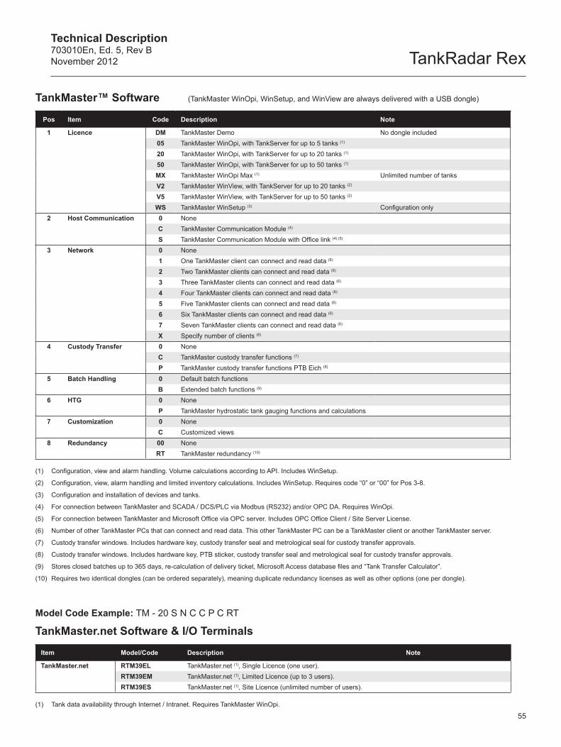
Technical Description703010En, Ed. 5, Rev BNovember 2012 TankRadar Rex
55
TankMaster™ Software (TankMaster WinOpi, WinSetup, and WinView are always delivered with a USB dongle)
Pos Item Code Description Note
1 Licence DM TankMaster Demo No dongle included05 TankMaster WinOpi, with TankServer for up to 5 tanks (1)
20 TankMaster WinOpi, with TankServer for up to 20 tanks (1)
50 TankMaster WinOpi, with TankServer for up to 50 tanks (1)
MX TankMaster WinOpi Max (1) Unlimited number of tanksV2 TankMaster WinView, with TankServer for up to 20 tanks (2)
V5 TankMaster WinView, with TankServer for up to 50 tanks (2)
WS TankMaster WinSetup (3) Configuration only2 Host Communication 0 None
C TankMaster Communication Module (4)
S TankMaster Communication Module with Office link (4) (5)
3 Network 0 None1 One TankMaster client can connect and read data (6)
2 Two TankMaster clients can connect and read data (6)
3 Three TankMaster clients can connect and read data (6)
4 Four TankMaster clients can connect and read data (6)
5 Five TankMaster clients can connect and read data (6)
6 Six TankMaster clients can connect and read data (6)
7 Seven TankMaster clients can connect and read data (6)
X Specify number of clients (6)
4 Custody Transfer 0 NoneC TankMaster custody transfer functions (7)
P TankMaster custody transfer functions PTB Eich (8)
5 Batch Handling 0 Default batch functionsB Extended batch functions (9)
6 HTG 0 NoneP TankMaster hydrostatic tank gauging functions and calculations
7 Customization 0 NoneC Customized views
8 Redundancy 00 NoneRT TankMaster redundancy (10)
(1) Configuration, view and alarm handling. Volume calculations according to API. Includes WinSetup.
(2) Configuration, view, alarm handling and limited inventory calculations. Includes WinSetup. Requires code “0” or “00” for Pos 3-8.
(3) Configuration and installation of devices and tanks.
(4) For connection between TankMaster and SCADA / DCS/PLC via Modbus (RS232) and/or OPC DA. Requires WinOpi.
(5) For connection between TankMaster and Microsoft Office via OPC server. Includes OPC Office Client / Site Server License.
(6) Number of other TankMaster PCs that can connect and read data. This other TankMaster PC can be a TankMaster client or another TankMaster server.
(7) Custody transfer windows. Includes hardware key, custody transfer seal and metrological seal for custody transfer approvals.
(8) Custody transfer windows. Includes hardware key, PTB sticker, custody transfer seal and metrological seal for custody transfer approvals.
(9) Stores closed batches up to 365 days, re-calculation of delivery ticket, Microsoft Access database files and “Tank Transfer Calculator”.
(10) Requires two identical dongles (can be ordered separately), meaning duplicate redundancy licenses as well as other options (one per dongle).
Model Code Example: TM - 20 S N C C P C RT
TankMaster.net Software & I/O Terminals
Item Model/Code Description Note
TankMaster.net RTM39EL TankMaster.net (1), Single Licence (one user).RTM39EM TankMaster.net (1), Limited Licence (up to 3 users).RTM39ES TankMaster.net (1), Site Licence (unlimited number of users).
(1) Tank data availability through Internet / Intranet. Requires TankMaster WinOpi.
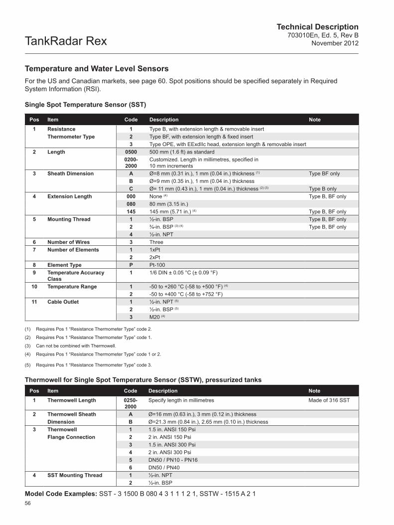
TankRadar RexTechnical Description
703010En, Ed. 5, Rev BNovember 2012
56
Temperature and Water Level SensorsFor the US and Canadian markets, see page 60. Spot positions should be specified separately in Required System Information (RSI).
Single Spot Temperature Sensor (SST)
Pos Item Code Description Note
1 Resistance 1 Type B, with extension length & removable insertThermometer Type 2 Type BF, with extension length & fixed insert
3 Type OPE, with EExdIIc head, extension length & removable insert2 Length 0500 500 mm (1.6 ft) as standard
0200-2000
Customized. Length in millimetres, specified in 10 mm increments
3 Sheath Dimension A Ø=8 mm (0.31 in.), 1 mm (0.04 in.) thickness (1) Type BF onlyB Ø=9 mm (0.35 in.), 1 mm (0.04 in.) thicknessC Ø= 11 mm (0.43 in.), 1 mm (0.04 in.) thickness (2) (3) Type B only
4 Extension Length 000 None (4) Type B, BF only080 80 mm (3.15 in.)145 145 mm (5.71 in.) (4) Type B, BF only
5 Mounting Thread 1 ½-in. BSP Type B, BF only2 ¾-in. BSP (3) (4) Type B, BF only4 ½-in. NPT
6 Number of Wires 3 Three7 Number of Elements 1 1xPt
2 2xPt8 Element Type P Pt-1009 Temperature Accuracy
Class1 1/6 DIN ± 0.05 °C (± 0.09 °F)
10 Temperature Range 1 -50 to +260 °C (-58 to +500 °F) (4)
2 -50 to +400 °C (-58 to +752 °F)11 Cable Outlet 1 ½-in. NPT (5)
2 ½-in. BSP (5)
3 M20 (4)
(1) Requires Pos 1 “Resistance Thermometer Type” code 2.
(2) Requires Pos 1 “Resistance Thermometer Type” code 1.
(3) Can not be combined with Thermowell.
(4) Requires Pos 1 “Resistance Thermometer Type” code 1 or 2.
(5) Requires Pos 1 “Resistance Thermometer Type” code 3.
Thermowell for Single Spot Temperature Sensor (SSTW), pressurized tanksPos Item Code Description Note
1 Thermowell Length 0250-2000
Specify length in millimetres Made of 316 SST
2 Thermowell Sheath A Ø=16 mm (0.63 in.), 3 mm (0.12 in.) thicknessDimension B Ø=21.3 mm (0.84 in.), 2.65 mm (0.10 in.) thickness
3 Thermowell 1 1.5 in. ANSI 150 PsiFlange Connection 2 2 in. ANSI 150 Psi
3 1.5 in. ANSI 300 Psi4 2 in. ANSI 300 Psi5 DN50 / PN10 - PN166 DN50 / PN40
4 SST Mounting Thread 1 ½-in. NPT2 ½-in. BSP
Model Code Examples: SST - 3 1500 B 080 4 3 1 1 1 2 1, SSTW - 1515 A 2 1
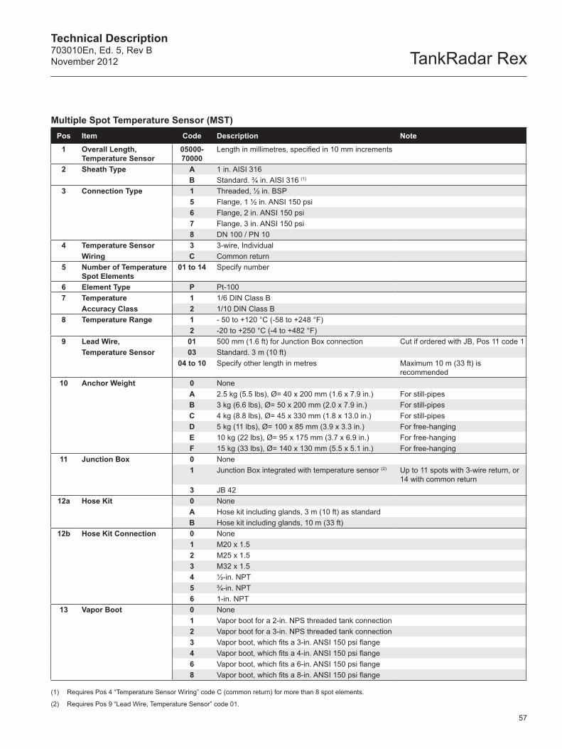
Technical Description703010En, Ed. 5, Rev BNovember 2012 TankRadar Rex
57
Multiple Sp ot Temperature Sensor (MST) Pos Item Code Description Note
1 Overall Length, Temperature Sensor
05000- 70000
Length in millimetres, specified in 10 mm increments
2 Sheath Type A 1 in. AISI 316B Standard. ¾ in. AISI 316 (1)
3 Connection Type 1 Threaded, ½ in. BSP5 Flange, 1 ½ in. ANSI 150 psi6 Flange, 2 in. ANSI 150 psi7 Flange, 3 in. ANSI 150 psi8 DN 100 / PN 10
4 Temperature Sensor 3 3-wire, IndividualWiring C Common return
5 Number of Temperature Spot Elements
01 to 14 Specify number
6 Element Type P Pt-1007 Temperature 1 1/6 DIN Class B
Accuracy Class 2 1/10 DIN Class B8 Temperature Range 1 - 50 to +120 °C (-58 to +248 °F)
2 -20 to +250 °C (-4 to +482 °F)9 Lead Wire, 01 500 mm (1.6 ft) for Junction Box connection Cut if ordered with JB, Pos 11 code 1
Temperature Sensor 03 Standard. 3 m (10 ft)04 to 10 Specify other length in metres Maximum 10 m (33 ft) is
recommended10 Anchor Weight 0 None
A 2.5 kg (5.5 lbs), Ø= 40 x 200 mm (1.6 x 7.9 in.) For still-pipesB 3 kg (6.6 lbs), Ø= 50 x 200 mm (2.0 x 7.9 in.) For still-pipesC 4 kg (8.8 lbs), Ø= 45 x 330 mm (1.8 x 13.0 in.) For still-pipesD 5 kg (11 lbs), Ø= 100 x 85 mm (3.9 x 3.3 in.) For free-hangingE 10 kg (22 lbs), Ø= 95 x 175 mm (3.7 x 6.9 in.) For free-hangingF 15 kg (33 lbs), Ø= 140 x 130 mm (5.5 x 5.1 in.) For free-hanging
11 Junction Box 0 None1 Junction Box integrated with temperature sensor (2) Up to 11 spots with 3-wire return, or
14 with common return3 JB 42
12a Hose Kit 0 NoneA Hose kit including glands, 3 m (10 ft) as standardB Hose kit including glands, 10 m (33 ft)
12b Hose Kit Connection 0 None1 M20 x 1.52 M25 x 1.53 M32 x 1.54 ½-in. NPT5 ¾-in. NPT6 1-in. NPT
13 Vapor Boot 0 None1 Vapor boot for a 2-in. NPS threaded tank connection2 Vapor boot for a 3-in. NPS threaded tank connection3 Vapor boot, which fits a 3-in. ANSI 150 psi flange4 Vapor boot, which fits a 4-in. ANSI 150 psi flange6 Vapor boot, which fits a 6-in. ANSI 150 psi flange8 Vapor boot, which fits a 8-in. ANSI 150 psi flange
(1) Requires Pos 4 “Temperature Sensor Wiring” code C (common return) for more than 8 spot elements.
(2) Requires Pos 9 “Lead Wire, Temperature Sensor” code 01.
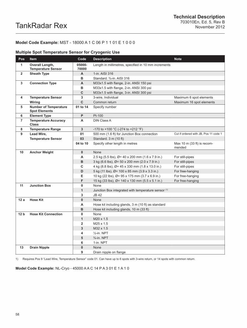
TankRadar RexTechnical Description
703010En, Ed. 5, Rev BNovember 2012
58
Model Code Example: MST - 18000 A 1 C 06 P 1 1 01 E 1 0 0 0
Multiple Sp ot Temperature Sensor for Cryogenic UsePos Item Code Description Note
1 Overall Length, Temperature Sensor
05000- 70000
Length in millimetres, specified in 10 mm increments
2 Sheath Type A 1-in. AISI 316B Standard. ¾-in. AISI 316
3 Connection Type A M33x1.5 with flange, 2-in. ANSI 150 psiB M33x1.5 with flange, 2-in. ANSI 300 psiC M33x1.5 with flange, 3-in. ANSI 300 psi
4 Temperature Sensor 3 3-wire, Individual Maximum 6 spot elementsWiring C Common return Maximum 16 spot elements
5 Number of Temperature Spot Elements
01 to 14 Specify number
6 Element Type P Pt-1007 Temperature Accuracy
ClassA DIN Class A
8 Temperature Range 3 -170 to +100 °C (-274 to +212 °F) 9 Lead Wire, 01 500 mm (1.6 ft) for Junction Box connection Cut if ordered with JB, Pos 11 code 1
Temperature Sensor 03 Standard. 3 m (10 ft)04 to 10 Specify other length in metres Max 10 m (33 ft) is recom-
mended10 Anchor Weight 0 None
A 2.5 kg (5.5 lbs), Ø= 40 x 200 mm (1.6 x 7.9 in.) For still-pipesB 3 kg (6.6 lbs), Ø= 50 x 200 mm (2.0 x 7.9 in.) For still-pipesC 4 kg (8.8 lbs), Ø= 45 x 330 mm (1.8 x 13.0 in.) For still-pipesD 5 kg (11 lbs), Ø= 100 x 85 mm (3.9 x 3.3 in.) For free-hangingE 10 kg (22 lbs), Ø= 95 x 175 mm (3.7 x 6.9 in.) For free-hangingF 15 kg (33 lbs), Ø= 140 x 130 mm (5.5 x 5.1 in.) For free-hanging
11 Junction Box 0 None1 Junction Box integrated with temperature sensor (1)
3 JB 4212 a Hose Kit 0 None
A Hose kit including glands, 3 m (10 ft) as standardB Hose kit including glands, 10 m (33 ft)
12 b Hose Kit Connection 0 None 1 M20 x 1.52 M25 x 1.53 M32 x 1.54 ½-in. NPT5 ¾-in. NPT 6 1-in. NPT
13 Drain Nipple 0 None9 Drain nipple on flange
1) Requires Pos 9 “Lead Wire, Temperature Sensor” code 01. Can have up to 6 spots with 3-wire return, or 14 spots with common return.
Model Code Example: NL-Cryo - 45000 A A C 14 P A 3 01 E 1 A 1 0
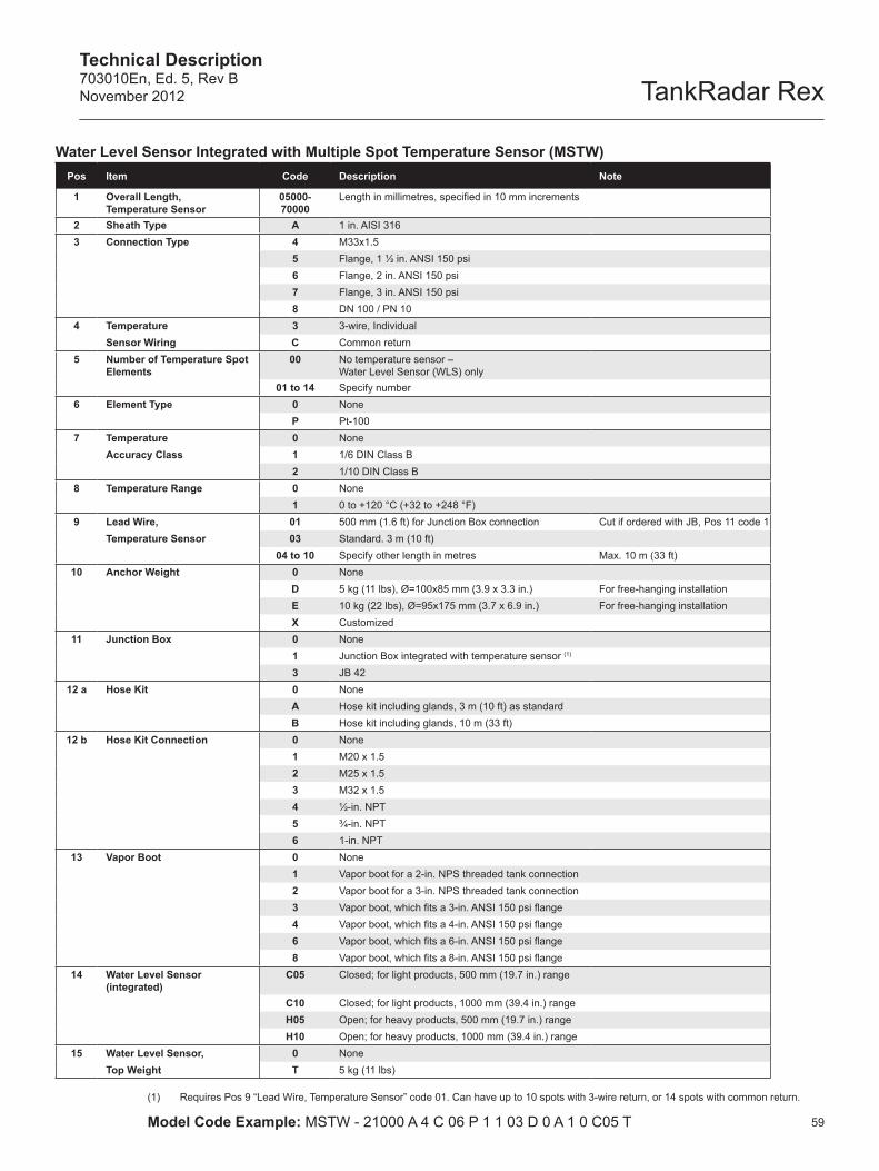
Technical Description703010En, Ed. 5, Rev BNovember 2012 TankRadar Rex
59
Water Level Sensor Integrated with Multiple Spot Temperature Sensor (MSTW)Pos Item Code Description Note
1 Overall Length, Temperature Sensor
05000- 70000
Length in millimetres, specified in 10 mm increments
2 Sheath Type A 1 in. AISI 3163 Connection Type 4 M33x1.5
5 Flange, 1 ½ in. ANSI 150 psi6 Flange, 2 in. ANSI 150 psi7 Flange, 3 in. ANSI 150 psi8 DN 100 / PN 10
4 Temperature 3 3-wire, IndividualSensor Wiring C Common return
5 Number of Temperature Spot Elements
00 No temperature sensor – Water Level Sensor (WLS) only
01 to 14 Specify number6 Element Type 0 None
P Pt-1007 Temperature 0 None
Accuracy Class 1 1/6 DIN Class B2 1/10 DIN Class B
8 Temperature Range 0 None1 0 to +120 °C (+32 to +248 °F)
9 Lead Wire, 01 500 mm (1.6 ft) for Junction Box connection Cut if ordered with JB, Pos 11 code 1Temperature Sensor 03 Standard. 3 m (10 ft)
04 to 10 Specify other length in metres Max. 10 m (33 ft) 10 Anchor Weight 0 None
D 5 kg (11 lbs), Ø=100x85 mm (3.9 x 3.3 in.) For free-hanging installationE 10 kg (22 lbs), Ø=95x175 mm (3.7 x 6.9 in.) For free-hanging installationX Customized
11 Junction Box 0 None1 Junction Box integrated with temperature sensor (1)
3 JB 4212 a Hose Kit 0 None
A Hose kit including glands, 3 m (10 ft) as standardB Hose kit including glands, 10 m (33 ft)
12 b Hose Kit Connection 0 None 1 M20 x 1.52 M25 x 1.53 M32 x 1.54 ½-in. NPT5 ¾-in. NPT 6 1-in. NPT
13 Vapor Boot 0 None1 Vapor boot for a 2-in. NPS threaded tank connection2 Vapor boot for a 3-in. NPS threaded tank connection3 Vapor boot, which fits a 3-in. ANSI 150 psi flange4 Vapor boot, which fits a 4-in. ANSI 150 psi flange6 Vapor boot, which fits a 6-in. ANSI 150 psi flange8 Vapor boot, which fits a 8-in. ANSI 150 psi flange
14 Water Level Sensor (integrated)
C05 Closed; for light products, 500 mm (19.7 in.) range
C10 Closed; for light products, 1000 mm (39.4 in.) rangeH05 Open; for heavy products, 500 mm (19.7 in.) rangeH10 Open; for heavy products, 1000 mm (39.4 in.) range
15 Water Level Sensor, 0 NoneTop Weight T 5 kg (11 lbs)
(1) Requires Pos 9 “Lead Wire, Temperature Sensor” code 01. Can have up to 10 spots with 3-wire return, or 14 spots with common return.
Model Code Example: MSTW - 21000 A 4 C 06 P 1 1 03 D 0 A 1 0 C05 T
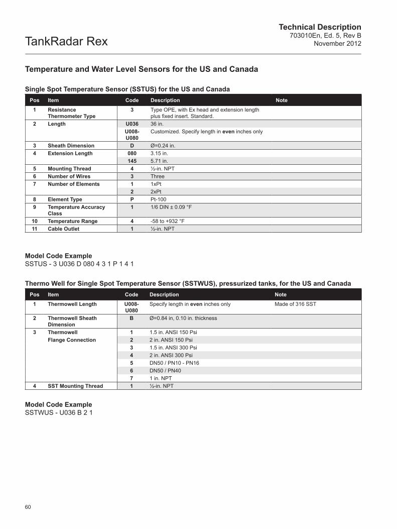
TankRadar RexTechnical Description
703010En, Ed. 5, Rev BNovember 2012
60
Temperature and Water Level Sensors for the US and Canada
Single Spot Temperature Sensor (SSTUS) for the US and CanadaPos Item Code Description Note
1 Resistance Thermometer Type
3 Type OPE, with Ex head and extension length plus fixed insert. Standard.
2 Length U036 36 in.U008-U080
Customized. Specify length in even inches only
3 Sheath Dimension D Ø=0.24 in.4 Extension Length 080 3.15 in.
145 5.71 in.5 Mounting Thread 4 ½-in. NPT6 Number of Wires 3 Three7 Number of Elements 1 1xPt
2 2xPt8 Element Type P Pt-1009 Temperature Accuracy
Class1 1/6 DIN ± 0.09 °F
10 Temperature Range 4 -58 to +932 °F 11 Cable Outlet 1 ½-in. NPT
Model Code ExampleSSTUS - 3 U036 D 080 4 3 1 P 1 4 1
Thermo Well for Single Spot Temperature Sensor (SSTWUS), pressurized tanks, for the US and CanadaPos Item Code Description Note
1 Thermowell Length U008-U080
Specify length in even inches only Made of 316 SST
2 Thermowell SheathDimension
B Ø=0.84 in, 0.10 in. thickness
3 Thermowell 1 1.5 in. ANSI 150 PsiFlange Connection 2 2 in. ANSI 150 Psi
3 1.5 in. ANSI 300 Psi4 2 in. ANSI 300 Psi5 DN50 / PN10 - PN166 DN50 / PN407 1 in. NPT
4 SST Mounting Thread 1 ½-in. NPT
Model Code ExampleSSTWUS - U036 B 2 1
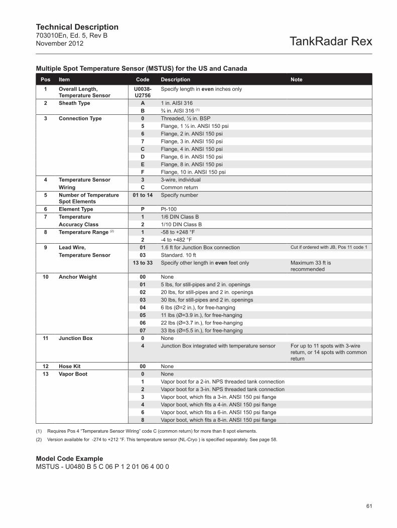
Technical Description703010En, Ed. 5, Rev BNovember 2012 TankRadar Rex
61
Multiple Spot Temperature Sensor (MSTUS) for the US and CanadaPos Item Code Description Note
1 Overall Length, Temperature Sensor
U0038- U2756
Specify length in even inches only
2 Sheath Type A 1 in. AISI 316B ¾ in. AISI 316 (1)
3 Connection Type 0 Threaded, ½ in. BSP5 Flange, 1 ½ in. ANSI 150 psi6 Flange, 2 in. ANSI 150 psi7 Flange, 3 in. ANSI 150 psiC Flange, 4 in. ANSI 150 psiD Flange, 6 in. ANSI 150 psiE Flange, 8 in. ANSI 150 psiF Flange, 10 in. ANSI 150 psi
4 Temperature Sensor 3 3-wire, individualWiring C Common return
5 Number of Temperature Spot Elements
01 to 14 Specify number
6 Element Type P Pt-1007 Temperature 1 1/6 DIN Class B
Accuracy Class 2 1/10 DIN Class B8 Temperature Range (2) 1 -58 to +248 °F
2 -4 to +482 °F9 Lead Wire, 01 1.6 ft for Junction Box connection Cut if ordered with JB, Pos 11 code 1
Temperature Sensor 03 Standard. 10 ft13 to 33 Specify other length in even feet only Maximum 33 ft is
recommended10 Anchor Weight 00 None
01 5 lbs, for still-pipes and 2 in. openings02 20 lbs, for still-pipes and 2 in. openings 03 30 lbs, for still-pipes and 2 in. openings04 6 lbs (Ø=2 in.), for free-hanging05 11 lbs (Ø=3.9 in.), for free-hanging06 22 lbs (Ø=3.7 in.), for free-hanging07 33 lbs (Ø=5.5 in.), for free-hanging
11 Junction Box 0 None4 Junction Box integrated with temperature sensor For up to 11 spots with 3-wire
return, or 14 spots with common return
12 Hose Kit 00 None13 Vapor Boot 0 None
1 Vapor boot for a 2-in. NPS threaded tank connection2 Vapor boot for a 3-in. NPS threaded tank connection3 Vapor boot, which fits a 3-in. ANSI 150 psi flange4 Vapor boot, which fits a 4-in. ANSI 150 psi flange6 Vapor boot, which fits a 6-in. ANSI 150 psi flange8 Vapor boot, which fits a 8-in. ANSI 150 psi flange
(1) Requires Pos 4 “Temperature Sensor Wiring” code C (common return) for more than 8 spot elements.
(2) Version available for -274 to +212 °F. This temperature sensor (NL-Cryo ) is specified separately. See page 58.
Model Code ExampleMSTUS - U0480 B 5 C 06 P 1 2 01 06 4 00 0
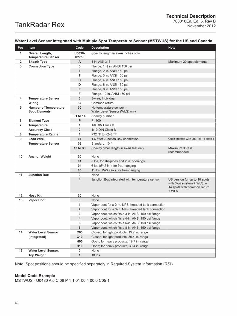
TankRadar RexTechnical Description
703010En, Ed. 5, Rev BNovember 2012
62
Water Level Sensor Integrated with Multiple Spot Temperature Sensor (MSTWUS) for the US and CanadaPos Item Code Description Note
1 Overall Length, Temperature Sensor
U0038- U2756
Specify length in even inches only
2 Sheath Type A 1 in. AISI 316 Maximum 20 spot elements3 Connection Type 5 Flange, 1 ½ in. ANSI 150 psi
6 Flange, 2 in. ANSI 150 psi7 Flange, 3 in. ANSI 150 psiC Flange, 4 in. ANSI 150 psiD Flange, 6 in. ANSI 150 psiE Flange, 8 in. ANSI 150 psiF Flange, 10 in. ANSI 150 psi
4 Temperature Sensor 3 3-wire, IndividualWiring C Common return
5 Number of Temperature Spot Elements
00 No temperature sensor – Water Level Sensor (WLS) only
01 to 14 Specify number6 Element Type P Pt-1007 Temperature 1 1/6 DIN Class B
Accuracy Class 2 1/10 DIN Class B8 Temperature Range 1 +32 °F to +248 °F9 Lead Wire, 01 1.6 ft for Junction Box connection Cut if ordered with JB, Pos 11 code 1
Temperature Sensor 03 Standard. 10 ft13 to 33 Specify other length in even feet only Maximum 33 ft is
recommended10 Anchor Weight 00 None
01 5 lbs, for still-pipes and 2 in. openings04 6 lbs (Ø=2 in.), for free-hanging05 11 lbs (Ø=3.9 in.), for free-hanging
11 Junction Box 0 None4 Junction Box integrated with temperature sensor US version for up to 10 spots
with 3-wire return + WLS, or 14 spots with common return + WLS
12 Hose Kit 00 None13 Vapor Boot 0 None
1 Vapor boot for a 2-in. NPS threaded tank connection2 Vapor boot for a 3-in. NPS threaded tank connection3 Vapor boot, which fits a 3-in. ANSI 150 psi flange4 Vapor boot, which fits a 4-in. ANSI 150 psi flange6 Vapor boot, which fits a 6-in. ANSI 150 psi flange8 Vapor boot, which fits a 8-in. ANSI 150 psi flange
14 Water Level Sensor C05 Closed; for light products, 19.7 in. range(integrated) C10 Closed; for light products, 39.4 in. range
H05 Open; for heavy products, 19.7 in. rangeH10 Open; for heavy products, 39.4 in. range
15 Water Level Sensor, 0 NoneTop Weight 1 10 lbs
Note: Spot positions should be specified separately in Required System Information (RSI).
Model Code ExampleMSTWUS - U0480 A 5 C 06 P 1 1 01 00 4 00 0 C05 1
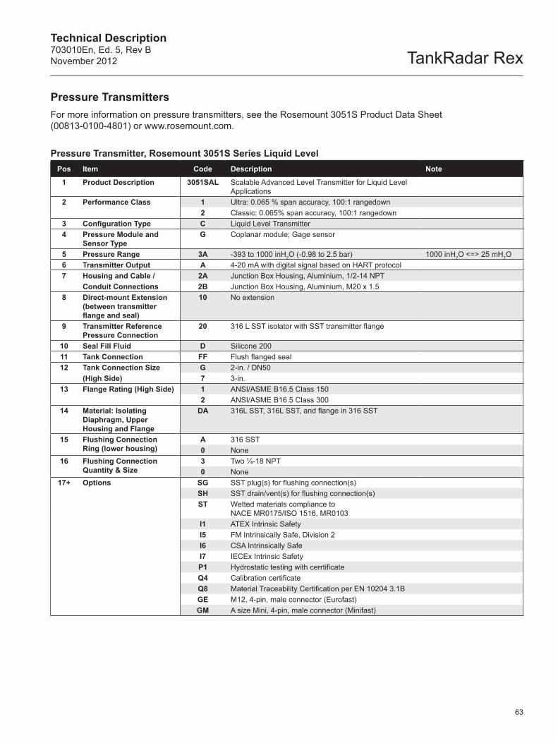
Technical Description703010En, Ed. 5, Rev BNovember 2012 TankRadar Rex
63
Pressure TransmittersFor more information on pressure transmitters, see the Rosemount 3051S Product Data Sheet (00813-0100-4801) or www.rosemount.com.
Pressure Transmitter, Rosemount 3051S Series Liquid LevelPos Item Code Description Note
1 Product Description 3051SAL Scalable Advanced Level Transmitter for Liquid Level Applications
2 Performance Class 1 Ultra: 0.065 % span accuracy, 100:1 rangedown2 Classic: 0.065% span accuracy, 100:1 rangedown
3 Configuration Type C Liquid Level Transmitter4 Pressure Module and
Sensor TypeG Coplanar module; Gage sensor
5 Pressure Range 3A -393 to 1000 inH2O (-0.98 to 2.5 bar) 1000 inH2O <=> 25 mH2O6 Transmitter Output A 4-20 mA with digital signal based on HART protocol7 Housing and Cable / 2A Junction Box Housing, Aluminium, 1/2-14 NPT
Conduit Connections 2B Junction Box Housing, Aluminium, M20 x 1.58 Direct-mount Extension
(between transmitter flange and seal)
10 No extension
9 Transmitter Reference Pressure Connection
20 316 L SST isolator with SST transmitter flange
10 Seal Fill Fluid D Silicone 20011 Tank Connection FF Flush flanged seal12 Tank Connection Size G 2-in. / DN50
(High Side) 7 3-in.13 Flange Rating (High Side) 1 ANSI/ASME B16.5 Class 150
2 ANSI/ASME B16.5 Class 30014 Material: Isolating
Diaphragm, Upper Housing and Flange
DA 316L SST, 316L SST, and flange in 316 SST
15 Flushing ConnectionRing (lower housing)
A 316 SST0 None
16 Flushing ConnectionQuantity & Size
3 Two ¼-18 NPT0 None
17+ Options SG SST plug(s) for flushing connection(s)SH SST drain/vent(s) for flushing connection(s)ST Wetted materials compliance to
NACE MR0175/ISO 1516, MR0103I1 ATEX Intrinsic SafetyI5 FM Intrinsically Safe, Division 2I6 CSA Intrinsically SafeI7 IECEx Intrinsic SafetyP1 Hydrostatic testing with cerrtificateQ4 Calibration certificateQ8 Material Traceability Certification per EN 10204 3.1BGE M12, 4-pin, male connector (Eurofast)GM A size Mini, 4-pin, male connector (Minifast)
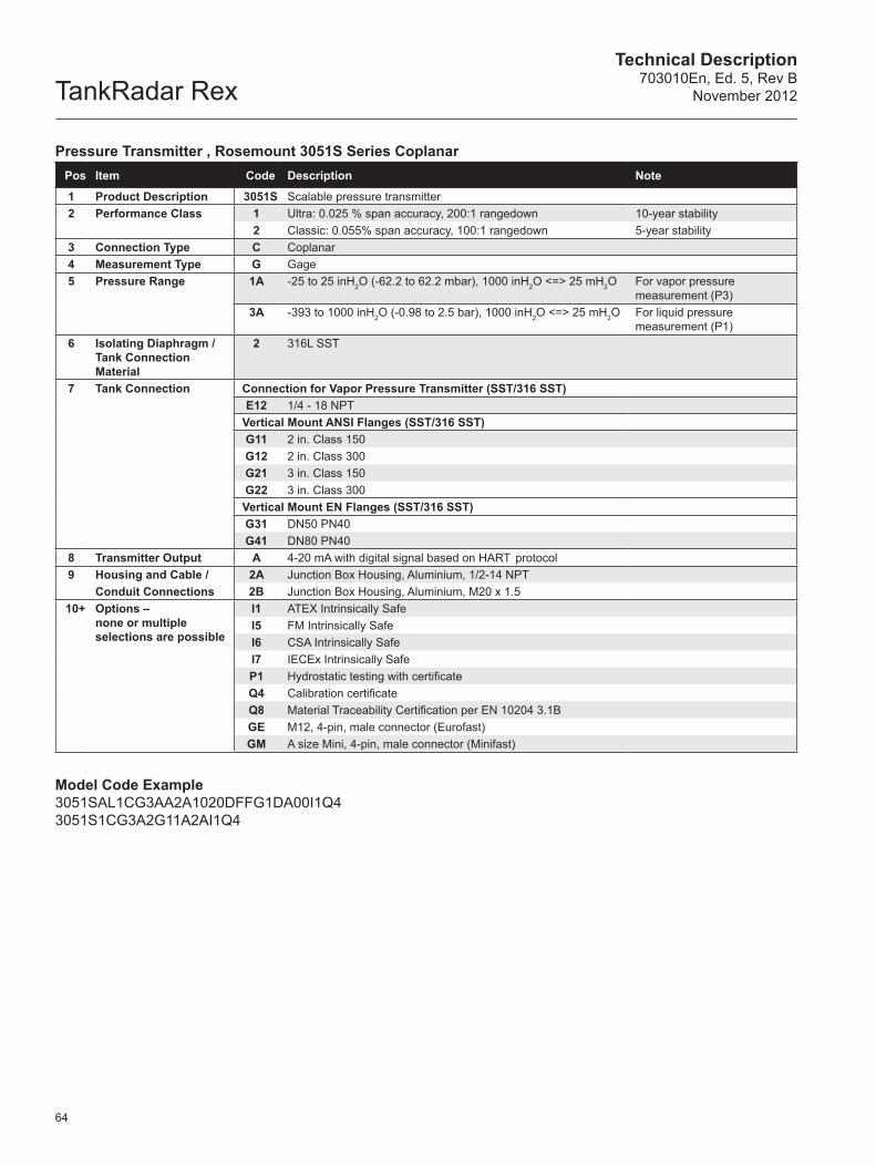
TankRadar RexTechnical Description
703010En, Ed. 5, Rev BNovember 2012
64
Pressure Transmitter , Rosemount 3051S Series CoplanarPos Item Code Description Note
1 Product Description 3051S Scalable pressure transmitter2 Performance Class 1 Ultra: 0.025 % span accuracy, 200:1 rangedown 10-year stability
2 Classic: 0.055% span accuracy, 100:1 rangedown 5-year stability3 Connection Type C Coplanar4 Measurement Type G Gage5 Pressure Range 1A -25 to 25 inH2O (-62.2 to 62.2 mbar), 1000 inH2O <=> 25 mH2O For vapor pressure
measurement (P3)3A -393 to 1000 inH2O (-0.98 to 2.5 bar), 1000 inH2O <=> 25 mH2O For liquid pressure
measurement (P1)6 Isolating Diaphragm /
Tank Connection Material
2 316L SST
7 Tank Connection Connection for Vapor Pressure Transmitter (SST/316 SST)E12 1/4 - 18 NPT
Vertical Mount ANSI Flanges (SST/316 SST)G11 2 in. Class 150G12 2 in. Class 300G21 3 in. Class 150G22 3 in. Class 300Vertical Mount EN Flanges (SST/316 SST)G31 DN50 PN40G41 DN80 PN40
8 Transmitter Output A 4-20 mA with digital signal based on HART protocol9 Housing and Cable / 2A Junction Box Housing, Aluminium, 1/2-14 NPT
Conduit Connections 2B Junction Box Housing, Aluminium, M20 x 1.510+ Options –
none or multiple selections are possible
I1 ATEX Intrinsically SafeI5 FM Intrinsically SafeI6 CSA Intrinsically SafeI7 IECEx Intrinsically SafeP1 Hydrostatic testing with certificateQ4 Calibration certificateQ8 Material Traceability Certification per EN 10204 3.1BGE M12, 4-pin, male connector (Eurofast)GM A size Mini, 4-pin, male connector (Minifast)
Model Code Example3051SAL1CG3AA2A1020DFFG1DA00I1Q4 3051S1CG3A2G11A2AI1Q4
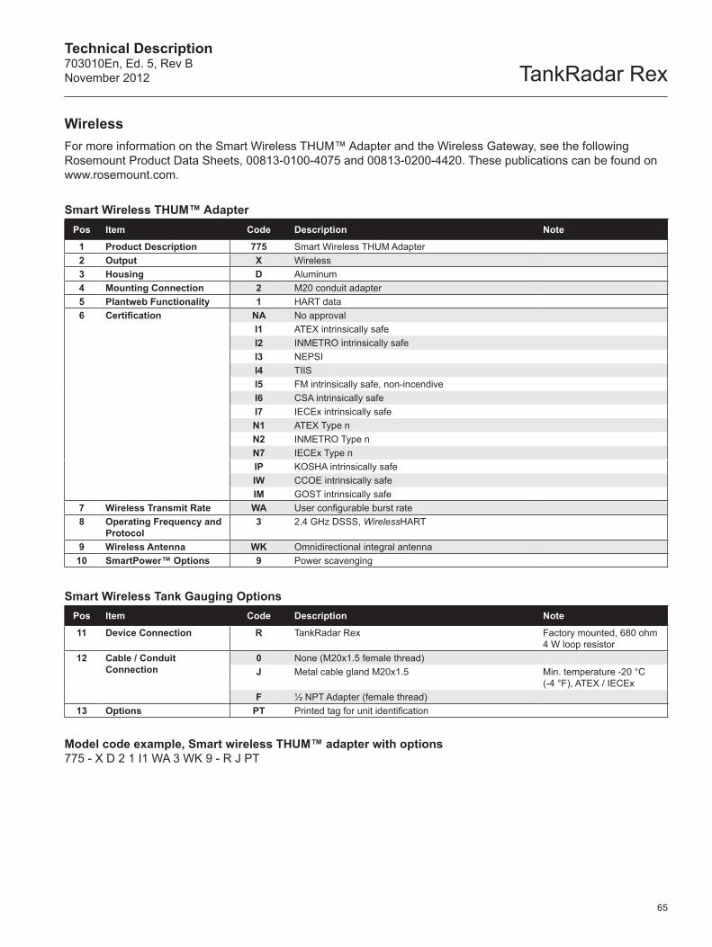
Technical Description703010En, Ed. 5, Rev BNovember 2012 TankRadar Rex
65
WirelessFor more information on the Smart Wireless THUM™ Adapter and the Wireless Gateway, see the following Rosemount Product Data Sheets, 00813-0100-4075 and 00813-0200-4420. These publications can be found on www.rosemount.com.
Smart Wireless THUM™ AdapterPos Item Code Description Note
1 Product Description 775 Smart Wireless THUM Adapter2 Output X Wireless3 Housing D Aluminum4 Mounting Connection 2 M20 conduit adapter5 Plantweb Functionality 1 HART data6 Certification NA No approval
I1 ATEX intrinsically safeI2 INMETRO intrinsically safeI3 NEPSII4 TIISI5 FM intrinsically safe, non-incendiveI6 CSA intrinsically safeI7 IECEx intrinsically safeN1 ATEX Type nN2 INMETRO Type nN7 IECEx Type nIP KOSHA intrinsically safeIW CCOE intrinsically safeIM GOST intrinsically safe
7 Wireless Transmit Rate WA User configurable burst rate8 Operating Frequency and
Protocol3 2.4 GHz DSSS, WirelessHART
9 Wireless Antenna WK Omnidirectional integral antenna10 SmartPower™ Options 9 Power scavenging
Smart Wireless Tank Gauging OptionsPos Item Code Description Note
11 Device Connection R TankRadar Rex Factory mounted, 680 ohm 4 W loop resistor
12 Cable / Conduit Connection
0 None (M20x1.5 female thread)J Metal cable gland M20x1.5 Min. temperature -20 °C
(-4 °F), ATEX / IECExF ½ NPT Adapter (female thread)
13 Options PT Printed tag for unit identification
Model code example, Smart wireless THUM™ adapter with options775 - X D 2 1 I1 WA 3 WK 9 - R J PT
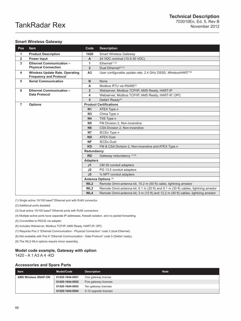
TankRadar RexTechnical Description
703010En, Ed. 5, Rev BNovember 2012
66
Smart Wireless GatewayPos Item Code Description
1 Product Description 1420 Smart Wireless Gateway2 Power Input A 24 VDC nominal (10.5-30 VDC)3 Ethernet Communication –
Physical Connection1 Ethernet(1) (2)
2 Dual Ethernet(3) (4)
4 Wireless Update Rate, Operating Frequency and Protocol
A3 User configurable update rate, 2.4 GHz DSSS, WirelessHART™
5 Serial Communication N NoneA Modbus RTU via RS485(5)
6 Ethernet Communication – Data Protocol
2 Webserver, Modbus TCP/IP, AMS Ready, HART-IP4 Webserver, Modbus TCP/IP, AMS Ready, HART-IP, OPC5 DeltaV Ready(6)
7 Options Product CertificationsN1 ATEX Type nN3 China Type nN4 TIIS Type nN5 FM Division 2, Non-incendiveN6 CSA Division 2, Non-incendiveN7 IECEx Type nND ATEX DustNF IECEx DustKD FM & CSA Division 2, Non-incendive and ATEX Type n
RedundancyRD Gateway redundancy (7) (8)
AdaptersJ1 CM 20 conduit adaptersJ2 PG 13.5 conduit adaptersJ3 ¾ NPT conduit adapters
Antenna Options (9)
WL2 Remote Omni-antenna kit, 15.2 m (50 ft) cable, lightning arrestorWL3 Remote Omni-antenna kit, 6.1 m (20 ft) and 9.1 m (30 ft) cables, lightning arrestorWL4 Remote Omni-antenna kit, 3 m (10 ft) and 12.2 m (40 ft) cables, lightning arrestor
(1) Single active 10/100 baseT Ethernet port with RJ45 connector.
(2) Additional ports disabled.
(3) Dual active 10/100 baseT Ethernet ports with RJ45 connectors.
(4) Multiple active ports have separate IP addresses, firewall isolation, and no packet forwarding.
(5) Convertible to RS232 via adapter.
(6) Includes Webserver, Modbus TCP/IP, AMS Ready, HART-IP, OPC.
(7) Requires Pos 3 “Ethernet Communication - Physical Connection” code 2 (dual Ethernet).
(8) Not available with Pos 6 “Ethernet Communication - Data Protocol” code 5 (DeltaV ready).
(9) The WL2-WL4 options require minor assembly.
Model code example, Gateway with option1420 - A 1 A3 A 4 -KD
Accessories and Spare PartsItem Model/Code Description Note
AMS Wireless SNAP-ON 01420-1644-0001 One gateway license01420-1644-0002 Five gateway licenses01420-1644-0003 Ten gateway licenses01420-1644-0004 5-10 upgrade licenses

TankRadar RexTechnical Description
703010En, Ed. 5, Rev B November 2012
2012 Rosemount Tank Radar AB, Sweden. All rights reserved.
Emerson Process ManagementRosemount Tank GaugingBox 13045S-402 51 GöteborgSWEDEN
Phone: +46 31 337 00 00Fax: +46 31 25 30 22E-mail: [email protected]