Embed Size (px)
Citation preview
10H-1
The Lease Pumper’s Handbook
Chapter 10The Tank Battery
Section H
TANK BATTERY DESIGN REVIEW
H-1. What Does a Tank Battery LookLike?
As indicated throughout this chapter, atank battery is designed to meet theparticular needs of the hydrocarbons cominginto it. Part of the production characteristicsthat affect the design of the tank batteryinclude:
· How many barrels of oil are producedeach day? This regulates the size of thetanks installed.
· How is the oil sold? How long is thetank unavailable due to being sold bypipe line? This helps determine howmany vessels are needed.
· How much gas is being produced andwhat is the shut-in pressure? Thisregulates how many pressurized vesselswill be required, and what pressure rangethe vessels may be subjected to. Theamount of gas also determines whetherpressurized vessels are required at all.
· How much water is being produced andwhat is the salt content?
· What is the gravity of the oil? Is it thinand fluid or thick and viscous when it isproduced cold? How much paraffin,asphalt, or sand is being produced? Howdifficult is it to remove the sand,especially fine sand with paraffin? Howdifficult is it to treat the oil?
· How corrosive is the water and whatother unique problems are encountered?
H-2. No Atmospheric Vessels.
When wells produce pipeline oil with nowater or paraffin, they can be flowed directlythrough the separator, through a LACT unit,and into the pipeline. The tank battery inFigure 1 contains a large horizontal standardseparator, a test separator, and a LACT unit.There are eleven flowing or gas lift wellsand no atmospheric vessels. It alsoeliminates the need for the circulating pump,water disposal and injection system, and allof the problems associated with oil treating.
The daily production is automaticallytransmitted to a computer and, if anythingunusual occurs in the daily production, analarm will be automatically recorded.
Figure 1. An 11-well tank battery thathas no stock tanks due to selling the oil
directly through a LACT unit.
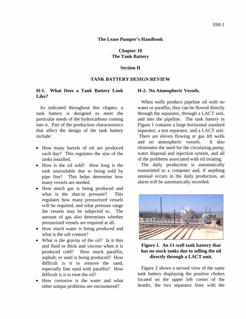
Figure 2 shows a second view of the sametank battery displaying the positive chokeslocated on the upper left corner of theheader, the two separator lines with the
10H-2
smaller test line, and an innovativeinstallation. An oil-saver hopper is locatedon the vertical line just below the positivechoke. Any residue oil can be poured intothe hopper and re-injected into the system bygas pressure through the 2-inch line actingas a volume tank by closing the choke valveand opening another.
Figure 2. A close up of the header andthe oil-saver hopper used on the tank
battery shown in Figure 1.
H-3. The Tank Battery Producing NoGas or Water.
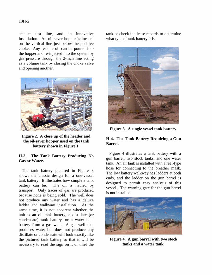
The tank battery pictured in Figure 3shows the classic design for a one-vesseltank battery. It illustrates how simple a tankbattery can be. The oil is hauled bytransport. Only traces of gas are producedbecause none is being sold. The well doesnot produce any water and has a deluxeladder and walkway installation. At thesame time, it is not apparent whether theunit is an oil tank battery, a distillate (orcondensate) tank battery, or a water tankbattery from a gas well. A gas well thatproduces water but does not produce anydistillate or condensate will look exactly likethe pictured tank battery so that it will benecessary to read the sign on it or thief the
tank or check the lease records to determinewhat type of tank battery it is.
Figure 3. A single vessel tank battery.
H-4. The Tank Battery Requiring a GunBarrel.
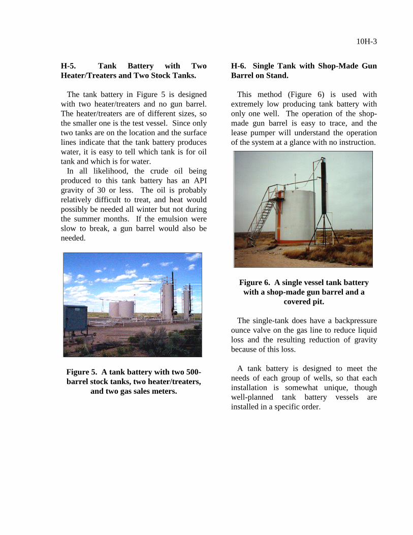
Figure 4 illustrates a tank battery with agun barrel, two stock tanks, and one watertank. An air tank is installed with a reel-typehose for connecting to the breather mask.The low battery walkway has ladders at bothends, and the ladder on the gun barrel isdesigned to permit easy analysis of thisvessel. The warning gate for the gun barrelis not installed.
Figure 4. A gun barrel with two stocktanks and a water tank.
10H-3
H-5. Tank Battery with TwoHeater/Treaters and Two Stock Tanks.
The tank battery in Figure 5 is designedwith two heater/treaters and no gun barrel.The heater/treaters are of different sizes, sothe smaller one is the test vessel. Since onlytwo tanks are on the location and the surfacelines indicate that the tank battery produceswater, it is easy to tell which tank is for oiltank and which is for water.
In all likelihood, the crude oil beingproduced to this tank battery has an APIgravity of 30 or less. The oil is probablyrelatively difficult to treat, and heat wouldpossibly be needed all winter but not duringthe summer months. If the emulsion wereslow to break, a gun barrel would also beneeded.
Figure 5. A tank battery with two 500-barrel stock tanks, two heater/treaters,
and two gas sales meters.
H-6. Single Tank with Shop-Made GunBarrel on Stand.
This method (Figure 6) is used withextremely low producing tank battery withonly one well. The operation of the shop-made gun barrel is easy to trace, and thelease pumper will understand the operationof the system at a glance with no instruction.
Figure 6. A single vessel tank batterywith a shop-made gun barrel and a
covered pit.
The single-tank does have a backpressureounce valve on the gas line to reduce liquidloss and the resulting reduction of gravitybecause of this loss.
A tank battery is designed to meet theneeds of each group of wells, so that eachinstallation is somewhat unique, thoughwell-planned tank battery vessels areinstalled in a specific order.

10H-4