Embed Size (px)
Citation preview
1
TANK BARGE DANGEROUS LIQUIDS
Student Manual
Maritime & Industrial
Training Center

2
MANUAL

3
4
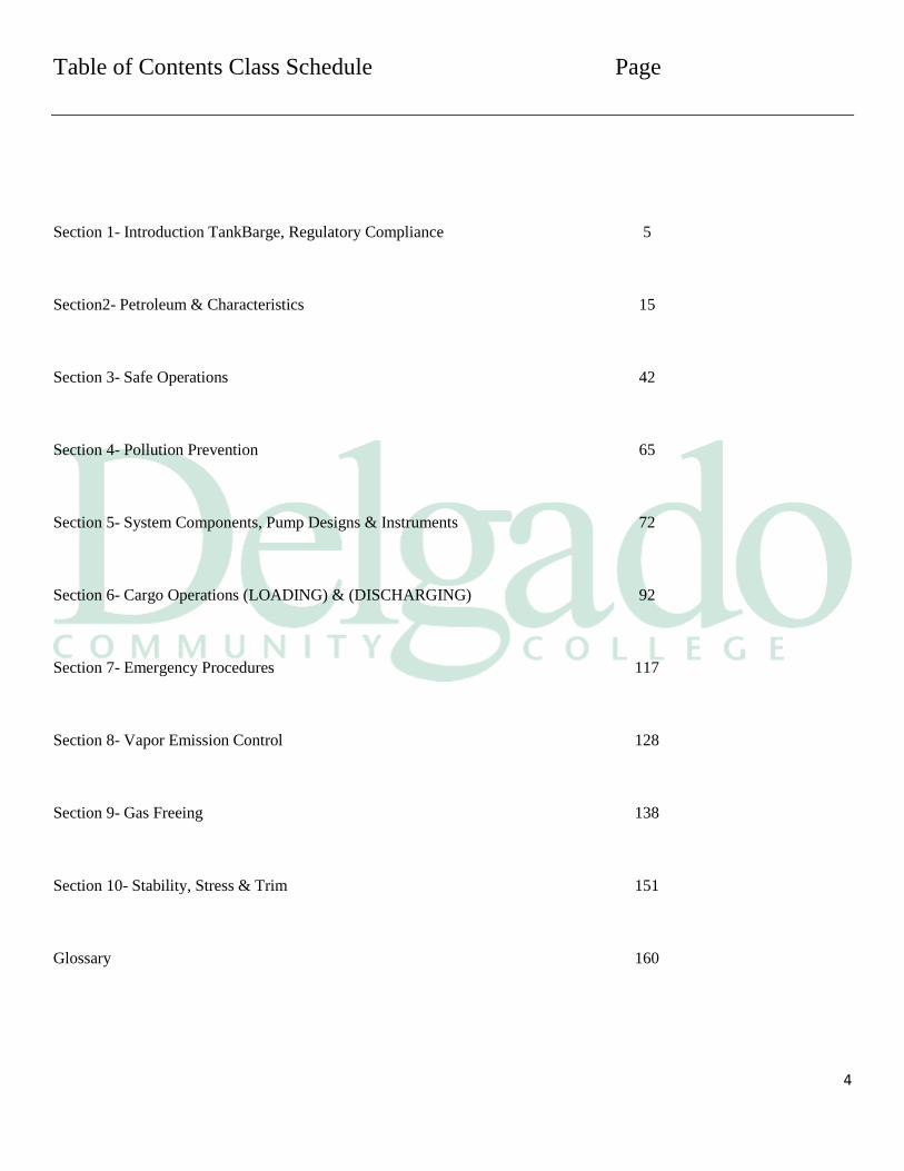
Table of Contents Class Schedule Page
Section 1- Introduction TankBarge, Regulatory Compliance 5
Section2- Petroleum & Characteristics 15
Section 3- Safe Operations 42
Section 4- Pollution Prevention 65
Section 5- System Components, Pump Designs & Instruments 72
Section 6- Cargo Operations (LOADING) & (DISCHARGING) 92
Section 7- Emergency Procedures 117
Section 8- Vapor Emission Control 128
Section 9- Gas Freeing 138
Section 10- Stability, Stress & Trim 151
Glossary 160

5
6
References:
Static Electric Discharge Hazard On Bulk Oil Tank Vessels- Phase 1 Report
Prepared for Commandant G-MTH-2, Engineering Branch US Coast Guard Headquarters
London Convention 1972 and 1996 Protocol, 2003 Edition
International Maritime Organization ISBN: 92-801-4155-4
Code of Federal Regulations 33CFR Subchapters M and 0 46CFR Subchapters D and 0
Standard Marine Navigational Vocabulary (IMO-985E) MARPOL 73/78 Consolidated Edition 2011 fifth edition, Annex I of MARPOL 73/78: Regulations for the Prevention of Pollution by Oil ISBN: 978-92-801-1532-1
Inert Gas Systems 1990 Edition, International Maritime Organization ISBN: 92-801-1262-7 ICS / OCIMF IAPH, International Safety Guide for Oil Tankers and Terminals (ISGOTT),
5TH edition, Witherby Seamanship International, 4 Dunlop Square, Deans Estate Livingston, EH54 8SB
U.K., Reprinted 2014 (ISBN 13: 978 1 85609 291 3 and 10: 1 85609 291 7)
Oil Pollution Act 1990.0PA 90 US Code, 1990
Tanker Operations: A Handbook for Person-in-Charge (PIC), by Mark E. Huber Fifth Edition 2010
Stability and Trim for the Ship's Officer, 4th Edition /by William E. George; based on the original by J.H. La Doge and L.
Van Gerent third printing 2010
Training Guidelines for Tank Vessel Personnel API Recommended Practice 1139
American Petroleum Institute, 2'nd Edition, 1993
Manual of Petroleum Measurement Standards Chapter 17.1 Guidelines for Marine Inspection American Petroleum
Institute, 2014
7
Manual of Petroleum Measurement Standards Chapter 17.0 Marine Measurement; Section 2- Measurement of Cargoes on
Board Tank Vessels, American Petroleum Institute, May 1999 – Reaffirmed September 2011
American Bureau of Shipping, Guild for Exhaust Emission Abatement, October 2013
Guide for Cargo Vapor Emission Control Systems on Board Tank Vessels American Bureau of Shipping, 1990
Vessel Spills. Prevention by Design Marine Board, 1991
Controlling Hydrocarbon Emission from Tank Vessel Loading Marine Board, 1987
Standard for Control of Gas Hazards on Vessels NFPA No.306
National Fire Protection Assn 2014 Edition
Navigation and Vessel Inspection Circular No. COMDTPUB P16700.4 NVIC 1-96 Subj: Safety standards for the
design and operation of a marine vapor control system (VCS) at tank barge cleaning facilities
Chemical Data Guide for Bulk Shipment by Water: Commandant Instruction M16616.6A, 08/11/1990
United States Coast Guard
Manual For The Safe Handling Of Flammable And Combustible Liquids And Other Hazardous Products CG-174 United
States Coast Guard, Department of transportation; September 1, 1976
Section 1
Regulatory Compliance
8
Introduction: Tank vessels operate under a variety of laws, rules and regulations. These interlocking
regulations form a web linking rules for operation and vessel construction on the:
International level
National level
Local levels
Organizations: In this module we will introduce you to the main organizations that implement and
enforce the regulations we live with. The organizations are as follows:
IMO
Marpol 73/78
Other international conventions
The U.S. Coast Guard
IMO: The International Maritime Organization is an international organization operating under
the auspices of the United Nations. The IMO has no direct regulatory authority. The IMO
regulations are agreed to:
By the member countries of the organization, or flag states
As set forth in conventions
By IMO regulatory compliance for International waters
Ratification: The flag state members and other countries ratify these conventions through their own
congresses or parliaments.
Treaties: When enough countries have ratified the conventions, they enter into force as
international treaties.
Modify Laws: It is incumbent upon each flag state member to modify its own national laws to:
Meet the standards of the conventions; or
Enact rules more stringent than the conventions
ISM: The International Safety Management (ISM) Code means the International Management
Code for the Safe Operation of Vessels and for Pollution Prevention adopted by IMO by
9
resolution A.741 and can be found in Annex 1 of SOLAS 1997 edition. The ISM Code
requires that the owners or operators shall:
Comply with the requirements of the ISM Code
Hold a Document of Compliance
Maintain its safety management system in accord with the ISM Code and be
subject to periodic verifications
TSMS: Towing Safety Management System is to be used as part of the proposed Subchapter M
requirements. The proposed requirements for the Towing Safety Management System
(TSMS) contained in 46 CFR 138.220(c) (2) states: “Procedures must be in place to
ensure safety of property, the environment and personnel.” But the procedures have not
been formalized by USCG to date.
August 2011: The U.S. Coast Guard announced publication in the Federal
Register of a notice of proposed rulemaking (NPRM) designed to improve safety
on towing vessels.
The NPRM provides a layered approach to towing vessel safety that includes the
option of an audited safety management system or an annual Coast Guard
inspection regime.
MARPOL 73/78: This acronym refers to the International Convention for the Prevention of Pollution from
Vessels, (Marine Pollution) 1973 as modified by the Protocol of 1978. This convention
covers pollution of the seas from all sources. The particular regulations are contained in
the following annexes:
Annex I: the Prevention of Pollution by Oil
The revised MARPOL Annex I (Oil) Regulations for the prevention of pollution
by oil was adopted in October 2004 and enters into force on 1 January 2007. It
incorporates the various amendments adopted since MARPOL entered into force
in 1983, including the amended regulation 13G (regulation 20 in the revised
annex) and regulation 13H (regulation 21in the revised annex) on the phasing-in
of double hull requirements
Annex II: the Control of Pollution by Noxious Liquid Substances;
The revised MARPOL73/78 Annex II (Noxious Liquid Substances) addresses
discharge criteria and measures for controlling pollution caused by noxious liquid
substances carried in bulk. About 250 substances have been evaluated and
included in a list appended to the Convention. Annex II limits at sea discharges
by requiring that discharge of residues be made to reception facilities, except
10
under specified conditions.
Other MARPOL Annexes
Annex Ill: the Prevention of Pollution by Harmful Substances in Packaged
Forms
Annex IV: the Prevention of Pollution by Sewage
Annex V: the Prevention of Pollution by Garbage
United States: There are many laws and regulations in the United States that governs oil or petro
chemicals shipping and Pollution.
Oil Pollution Act of 1961
The Federal Water Pollution Control Act
The Clean Water Act
The Ports and Waterways Safety Act
The Port and Tanker Safety Act
The Act to Prevent Pollution from Ships
Regulations set forth by the government's regulatory agencies (Code of Federal
Regulations, CFR); and
State laws and local ordinances.
More Stringent: If a state or local regulation is more stringent than the national or international regulation,
the more stringent regulation shall apply.
FWPCA: The Federal Water Pollution Control Act (FWPCA) was amended by the Clean
Water Act (CWA) and both names are now in general use for the statute. The FWPCA
was further amended by the passage of OPA90. It is codified at 33USC§1251etseq.This
legislation prohibits discharges of oil or hazardous substances, in such quantities as may
Into or upon the navigable waters of the U.S., adjoining shorelines, or into or
upon waters of the contiguous zone or
Which may affect natural resources in the U.S. Exclusive Economic Zone (EEZ)
OPA 90: OPA90 revised the FWPCA to strengthen and expand the nation's oil and hazardous
substances spill prevention, preparedness, and response activities. It further required
the President to promulgate an amended National Oil and Hazardous Substances
Pollution Contingency Plan (NCP) that expands the Federal government’s removal
authority, increases the responsibility of Federal OSCs during responses, and broadens
11
coordination and preparedness planning requirements. OPA90 requires that the NCP
describe the duties and responsibilities assigned to new OPA90-created entities like the
National Strike Force Coordination Center (NSFCC), for better coordination and
execution of Federal response efforts.
Under OPA90, vessel and facility owners and operators must develop oil and hazardous
substances response plans. It is part of the U.S. Code 33 USC 2701 and some of the
mandates are as follows:
All oil barges in U.S. waters will be double hulled by the year 2015
Minimum under hull clearances are now specified in 33 CFR 157.455
Escort tugs for single hull barges are mandated in certain waters
Limitations on the hours of work for crewmembers
Chemical Data Guide for Bulk Shipment by Water:
This is published as COMDTINST M16616.6A and previously as CG-174. This guide
was developed in the interest of safe water movement of bulk chemicals. It can help
prevent or at least minimize the harmful effects of chemical accidents on the waterways.
Although this guide is intended to be helpful in the initial stages of emergencies, users
should seek more detailed, specific and competent emergency medical services as soon as
possible. However, it is the publication the USCG uses in their deck examinations.
12
Dangerous Liquid Definition of “Dangerous Liquid”- A dangerous liquid is a liquid which is classified as
hazardous when transported in bulk by the USCG in 46 CFR 153.40 Every Subpart has
a definition section. If it does not give you a Regulation the Table will be at the back.
46 CFR 153.40- Determination of materials that are hazardous.
THE COAST GUARD HAS FOUND THE FOLLOWING MATERIALS TO BE
HAZARDOUS WHEN TRANSPORTED IN BULK:
(A) MATERIALS LISTED IN TABLE 30.25-1 OF THIS CHAPTER
(B) MATERIALS LISTED IN TABLE 151.05
(C) MATERIALS LISTED IN TABLE 1
(D) MATERIALS LISTED IN TABLE 4 OF PART 154
PART 151 BARGES CARRYING BULK LIQUID HAZARDOUS MATERIAL
CARGOS
PART 153 SHIPS CARRYING BULK LIQUID, LIQUIFIED GAS OR COMPRESSED
GAS HAZARDOUS MATERIALS
PART 154 SHIPS SAFETY STANDARDS FOR SELF PROPELLED VESSELS
CARRYING BULK
CFR Defined: The Code of Federal Regulations is the means by which the U.S. Code is implemented.
Congress grants the agencies that will be enforcing the laws:
The right to make the regulations; which
Will force compliance with the intent of Congress.
CFR's of Concern: The Coast Guard CFRs of most concern to tank vessel operators are:
13
33 CFR Subchapter M: Marine Pollution,
Financial Responsibility and Compensation (Parts 130 to 138);
33 CFR Subchapter G: Pollution (Parts 151 to 159) ;
46 CFR Subchapter D: Tank Vessels (Parts 30 to 39); and
46 CFR Subchapter O: Certain Bulk Dangerous Cargoes (Parts 150 to 155).
Local Rules: Many states and localities within the U.S. have their own regulations concerning barges.
These rules are valid and must be followed unless the Federal Government has preempted
them. State and local regulations can cover a variety of items, such as:
Additional firefighting equipment
Additional liability for pollution damage
Escort tugs in certain areas
Limitations on anchorage areas, and
Activities that may be conducted in them
Company Policy: Each company operating oil vessels, in meeting the ISM Code, will have a series of
instructions on how they want their vessels operated incorporated in the companies
Vessel Operating Manual. Some of the covered chapters would be:
The pollution policy
The quality policy
In port operations
Navigational policy
Safety policy
Emergency situation policies
Training policy
The duties of each rating on board
Stability Letter: A Stability Letter listing the basic operation a limits and guidance in a few pages is
common for smaller vessels and is typically posted in the wheelhouse. A Trim and
Stability Booklet contains more detailed instructions and includes forms for the Master
to actually calculate the weight and center of gravity of the vessel. Curves of the
maximum allowable center of gravity are then used to determine if the loaded condition
meets the required criteria.
14
Regulatory Compliance: Proof of a company or vessel to be in compliance with the regulations comes in the form
of certificates. The flag state is responsible for issuing these certificates to the vessels.
Some of these certificates are:
Cargo Vessel Safety Construction Certificate with the oil vessel Supplement,
states that compliance with the structural requirements of SOLAS 1974 is
certified;
Cargo Vessel Safety Equipment Certificate with the oil vessel Supplement, states
that compliance with the equipment requirements of SOLAS 1974 is certified;
The International Oil Pollution Prevention Certificate with Supplement B, states
that compliance with construction and equipment requirements of MARPOL
73/78 is certified.
PIC Tankerman: The PIC-Tankerman of an oil or chemical vessel is responsible for the operational
requirements of those regulations. The PIC-Tankerman will have the regulations in his
CFR library for reference.
In the U.S. PIC-Tankerman Tankship regulations (CFR's) require that officers in
charge of cargo operations (generally deck officers) on self-propelled tank
vessels must be certified as Tankerman PIC (Person In Charge).
For the domestic inland oil barge service and PIC-Tankerman must hold a
tankbarge rating on their MMD. With a DL (dangerous liquids) endorsement
which covers both oil and chemical barges, and the LG endorsement which
covers liquefied gas cargoes.
No certificate maybe issue unless the student has successfully completed an
approved course with the appropriate curriculum outlined in Table 13.121(e)
or §13.121(f).
Pollution: For many reasons, oil vessels can cause marine environmental pollution. As per 33 CFR
2716 and OPA 90 Section 1016, the owner is financially liable for clean-up costs and
other damages and also for:
15
Being required to be insured against such damages by a number of maritime
countries, Party to the International Convention on Civil Liability for Oil
Pollution
Having proof on board the vessel in the form of the Certificate of Insurance
issued by the flag state
The owner’s limits of liability for oil pollution damage
Being in accordance with her tonnage as set by the convention
NOTE: The owner cannot limit his liability if an oil pollution incident occurred
as a result of his fault or privy
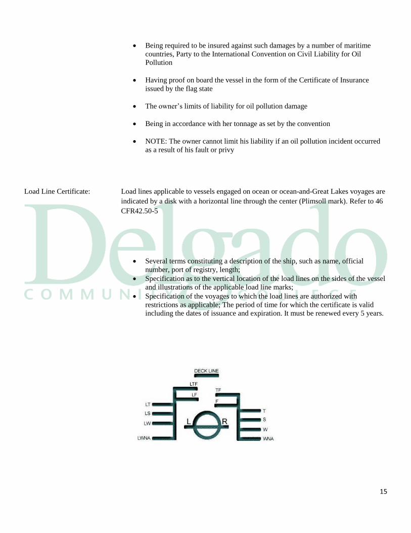
Load Line Certificate: Load lines applicable to vessels engaged on ocean or ocean-and-Great Lakes voyages are
indicated by a disk with a horizontal line through the center (Plimsoll mark). Refer to 46
CFR42.50-5
Several terms constituting a description of the ship, such as name, official
number, port of registry, length;
Specification as to the vertical location of the load lines on the sides of the vessel
and illustrations of the applicable load line marks;
Specification of the voyages to which the load lines are authorized with
restrictions as applicable; The period of time for which the certificate is valid
including the dates of issuance and expiration. It must be renewed every 5 years.
16
1.1 Vessel Terminology and Arrangements
Introduction: Vessels used to be classified by their trade. Barges come in a variety of types and trades.
Recently, with the increasing specialization of barges, the requirements of OPA 90.
Product Barges: These vessels carry finished products that are usually compatible hydrocarbon based
products in coated tanks and they can:
Carry a single lot or a multi-grade load
Load or discharge in one or several destinations
Backhaul cargo
Have a more complex cargo systems than crude carriers
Have more complicated carriage requirements
Their operations are more complicated
Chemical Barges: These are the most complex of the traditional barge types. They carry finished products
like the product carrier, but in smaller lots and usually many more grades. They have
more potential problems than product carriers which include:
17
Incompatibility between grades of cargo
Loading multi-parcel cargoes from several docks
Discharging to multiple docks
A high risk of personnel exposure and fatigue is common
OPA 90/IMO: Under OPA 90 and similar IMO regulations vessels are classed as either single hull or
double hull.
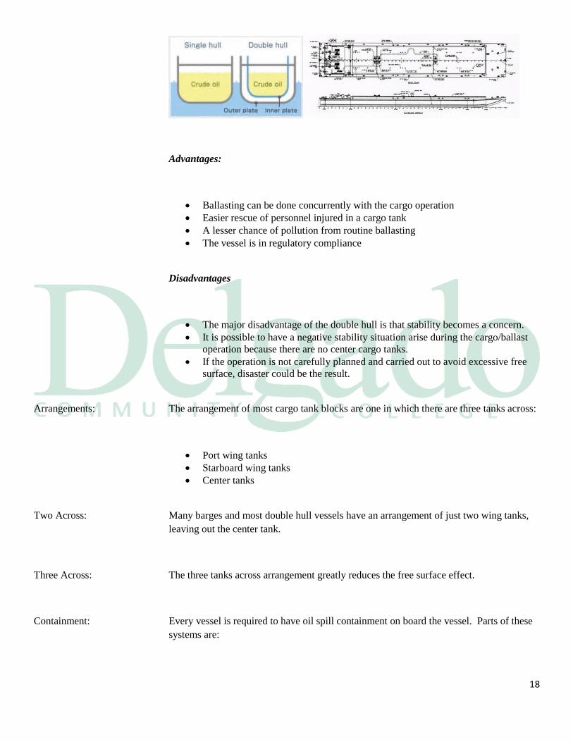
Single Hull: The single hull vessels have one layer of shell plating over its frames. The hull is the only
barrier between the sea and the cargo. All of the hull's strength members are located
within the tanks, such as the: Single skin barges are to be phase out for oil service by end
2015.
Double Bottom: Over the last twenty-five years many single hull vessels were built with double bottoms
for use as ballast tanks. Even though these vessels have double bottoms, they are still
classed as single hull. Essentially, double hull vessels have a second hull with the entire
cargo tank block surrounded by bulkheads and a bottom, creating a void space between
the cargo spaces and the external hull. This void space usually contains:
Clean segregated ballast;
Ballast piping; and
The vessel's internal framework and structural members.
Double Hull: Vessels have a second hull with the entire cargo tankblock surrounded by bulkheads
and a bottom, creating a void space between the cargo spaces and the external hull.
This void space usually contains:
Clean segregated ballast
Ballast piping, and the vessel’s internal framework and structural members
A lesser chance of a pollution incident
Easier cargo tank cleaning
18
Advantages:
Ballasting can be done concurrently with the cargo operation
Easier rescue of personnel injured in a cargo tank
A lesser chance of pollution from routine ballasting
The vessel is in regulatory compliance
Disadvantages
The major disadvantage of the double hull is that stability becomes a concern.
It is possible to have a negative stability situation arise during the cargo/ballast
operation because there are no center cargo tanks.
If the operation is not carefully planned and carried out to avoid excessive free
surface, disaster could be the result.
Arrangements: The arrangement of most cargo tank blocks are one in which there are three tanks across:
Port wing tanks
Starboard wing tanks
Center tanks
Two Across: Many barges and most double hull vessels have an arrangement of just two wing tanks,
leaving out the center tank.
Three Across: The three tanks across arrangement greatly reduces the free surface effect.
Containment: Every vessel is required to have oil spill containment on board the vessel. Parts of these
systems are:
19
The fishplate around the cargo deck
The manifold drip pans
Scupper plugs
Empty barrels
A portable pumps on the cargo deck with a hose attached
Absorbent pads
Spill cleanup gear
Barge hull classifications
As per 46 §151.10:
Type I barge hull. Barge hulls classed as Type I are those designed to carry
products which require the maximum preventive measures to preclude the
uncontrolled release of the cargo. These barges are required to meet:
Type II barge hull. Barge hulls classed as Type II are those designed to carry
products which require significant preventive measures to preclude the
uncontrolled release of the cargo. These barges are required to meet:
Type III barge hull. Barge hulls classed as Type III are those designed to carry
products of sufficient hazard to require a moderate degree of control
Hull structural requirements:
Types I, II, and III barges shall comply with the basic structural requirements of
the American Bureau of Shipping for barges of the ordinary types and the
applicable supplementary requirements of this section.
Types I and II barges in inland service: A grounding condition shall be assumed
where the forward rake bulkhead rests upon a pinnacle at the water surface.
Independent tanks supported by only two saddles do not contribute to the
strength and stiffness of the barge hull.
Independent tanks supported by three or more saddles contribute to the strength
and stiffness of the hull.
Cofferdam: The term cofferdam means a void or empty space separating two or more compartments
for the purpose of isolation or to prevent the contents of one compartment from entering
another in the event of the failure of the walls of one to retain their tightness.
46 CFR 30.10-13
20
Products to be Carried The products carried by a barge are listed on the Certificate of Inspection for that
particular barge as per 46 CFR 151.04-1(c)
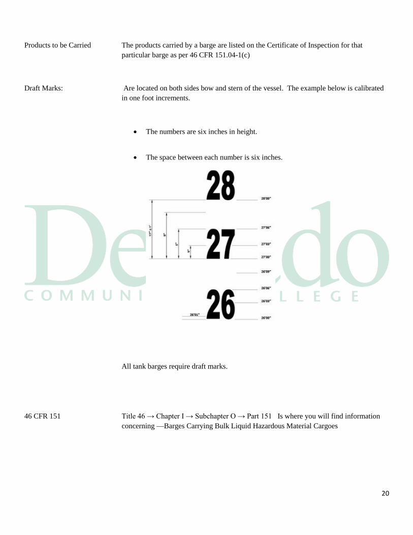
Draft Marks: Are located on both sides bow and stern of the vessel. The example below is calibrated
in one foot increments.
The numbers are six inches in height.
The space between each number is six inches.
All tank barges require draft marks.
46 CFR 151 Title 46 → Chapter I → Subchapter O → Part 151 Is where you will find information
concerning —Barges Carrying Bulk Liquid Hazardous Material Cargoes
21
Cargo Heating: Many oils and products require heating in order for them to be pump able. Among these
types of oil are:
Asphalt (bitumen);
Heavy lube oils;
High pour point gas oils;
Heavy fuel oils; and
Some crude oils.
Cargo Heating: Except for asphalt cargoes, heating is usually done by means of steam or hot oil coils
heating along the bottom of tank. The amount of heating required depends on several
factors:
The pour point of the cargo;
The flash point of the cargo;
The temperature limit for the tank coatings;
The temperature at which the cargo ordered to be at;
The ambient temperature; and
The daily temperature readings.
Problems: Heating coils can be a real problem on the vessels and some of these are:
Overheating the cargo;
Excessive fuel oil consumption;
The coils can put water in the cargo; and
The return line can introduce oil into
Other Types: Another type of heating arrangement is the heat exchanger rather than the traditional
coils. A heater is placed on the deck and cargo is pumped:
From the tank;
Through the exchanger; and
Back to the tank.
Slop Tanks: Heating systems can be placed in slop tanks to make the separation of oil/water more
efficient.
22
Section 2
Basic Characteristics of Petroleum and Its Measurement
Purpose: A general knowledge of the basic material with which we work will help us to better
perform our duties in relation to petroleum. This module will give the student a basic
understanding of just what petroleum is and information on its basic properties.
Composition: Petroleum is a chemical compound made up of various arrangements of hydrogen and
carbon atoms.
Structure: The structure consists of hydrogen atoms linked in many different ways to carbon atoms.
The nature of these links determines the type of the hydrocarbon compound.
Hydrocarbons can be defined in terms of their molecular weight, but for practical
purposes we would only be concerned with whether at normal atmospheric temperatures
and pressures that the compound is:
23
A gas; In a gas the molecular forces are very weak. A gas fills its container,
taking both the shape and the volume of the container
A liquid; In a liquid the molecular forces are weaker than in a solid. A liquid will
take the shape of its container with a free surface in a gravitational field. In
microgravity, a liquid forms a ball inside a free surface. Regardless of gravity, a
liquid has a fixed volume
A solid; In a solid the molecules are closely bound to one another by molecular
forces. A solid holds its shape and the volume of a solid is fixed by the shape of
the solid.
Matter can change state to solids, liquids, and gases and has different properties
controlled by heating or cooling. (Water is the only substance that naturally changes into
all three states of matter and makes life possible on earth). Heating involves melting or
evaporation, depending on the substances melting point or boiling point, respectively.
Carbon Atoms: It is the number of carbon atoms in each molecule that determines the normal physical
state of the hydrocarbon molecule and this relation vessel is:
4 carbon atoms is a gaseous state
5-24 carbon atoms is a liquid state
More than 24 carbon atoms is solid state
Viscosity: Is the amount of the resistance to flow in a fluid
Sour crude oil: Contains high quantities of hydrogen sulfide
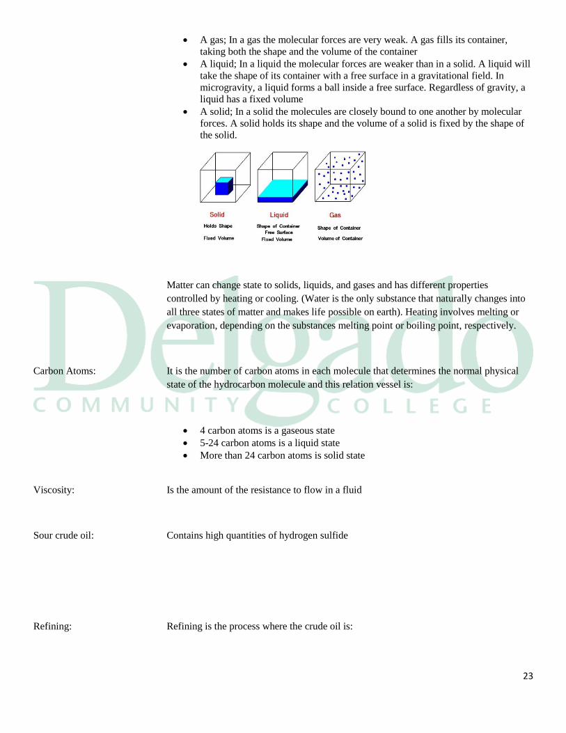
Refining: Refining is the process where the crude oil is:
24
Separated into fractions of petroleum molecules;
Where each fraction is a range of petroleum
molecules of similar weight; and
The molecular structure remains unchanged.
25
Cracking: Cracking changes the hydrocarbon molecules by using molecular structure of the various
chemical processes. Long chains of hydrocarbon molecules are broken up into shorter
ones creating lighter fractions
Fractional distillation: The first step in the refining process is the separation of crude oil into various fractions or
straight-run cuts by distillation in atmospheric and vacuum towers. The main fractions or
"cuts" obtained have specific boiling-point ranges and can be classified in order of
decreasing volatility into gases, light distillates, middle distillates, gas oils, and residuum
Chains Broken Demands: Refiners are able to change their output to meet seasonal demands through this process
Boiling Point: All of the crude oils and most refined products are mixtures of a wide range of
hydrocarbon compounds. The boiling points of these compounds range from -162°C to
well in excess of 400°C.
Volatility (chemistry): In chemistry and physics, volatility is the tendency of a substance to vaporize. Volatility
is directly related to a substance's Vapor Pressure. At a given temperature, a substance
with Higher Vapor Pressure vaporizes more readily than a substance with a Lower Vapor
Pressure.
26
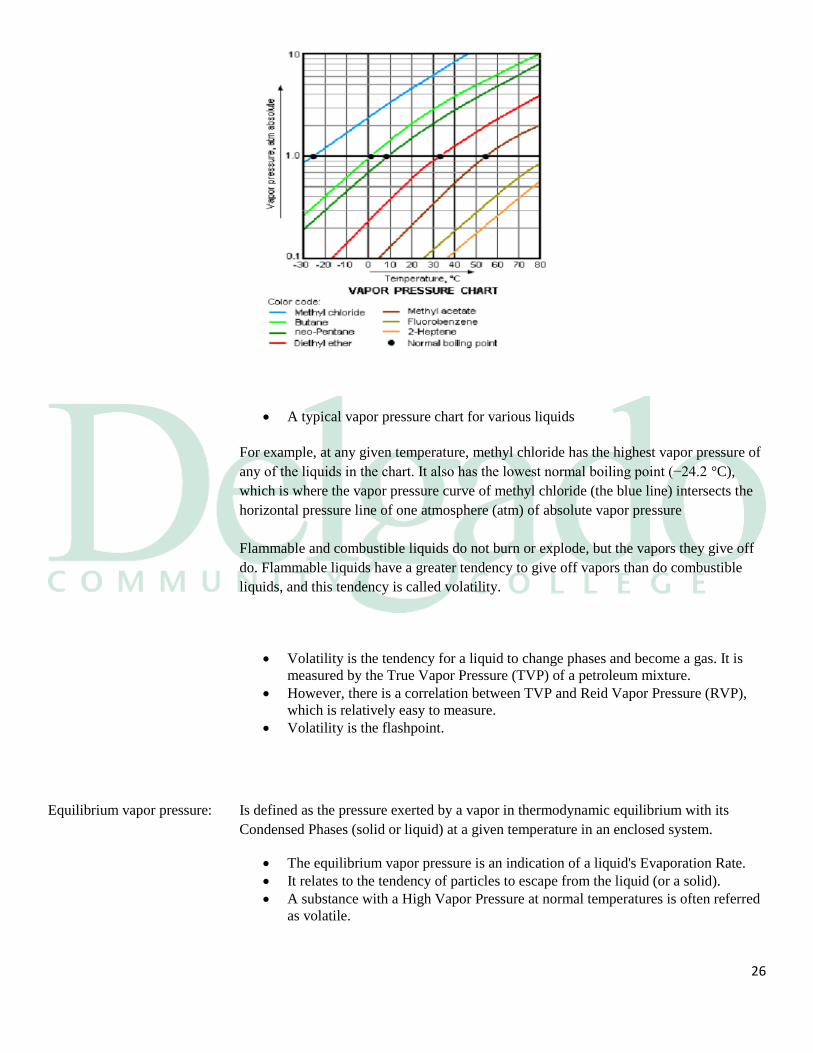
A typical vapor pressure chart for various liquids
For example, at any given temperature, methyl chloride has the highest vapor pressure of
any of the liquids in the chart. It also has the lowest normal boiling point (−24.2 °C),
which is where the vapor pressure curve of methyl chloride (the blue line) intersects the
horizontal pressure line of one atmosphere (atm) of absolute vapor pressure
Flammable and combustible liquids do not burn or explode, but the vapors they give off
do. Flammable liquids have a greater tendency to give off vapors than do combustible
liquids, and this tendency is called volatility.
Volatility is the tendency for a liquid to change phases and become a gas. It is
measured by the True Vapor Pressure (TVP) of a petroleum mixture.
However, there is a correlation between TVP and Reid Vapor Pressure (RVP),
which is relatively easy to measure.
Volatility is the flashpoint.
Equilibrium vapor pressure: Is defined as the pressure exerted by a vapor in thermodynamic equilibrium with its
Condensed Phases (solid or liquid) at a given temperature in an enclosed system.
The equilibrium vapor pressure is an indication of a liquid's Evaporation Rate.
It relates to the tendency of particles to escape from the liquid (or a solid).
A substance with a High Vapor Pressure at normal temperatures is often referred
as volatile.
27
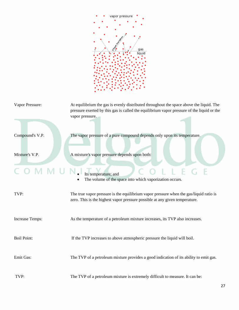
Vapor Pressure: At equilibrium the gas is evenly distributed throughout the space above the liquid. The
pressure exerted by this gas is called the equilibrium vapor pressure of the liquid or the
vapor pressure.
Compound's V.P. The vapor pressure of a pure compound depends only upon its temperature.
Mixture's V.P. A mixture's vapor pressure depends upon both:
Its temperature; and
The volume of the space into which vaporization occurs.
TVP: The true vapor pressure is the equilibrium vapor pressure when the gas/liquid ratio is
zero. This is the highest vapor pressure possible at any given temperature.
Increase Temps: As the temperature of a petroleum mixture increases, its TVP also increases.
Boil Point: If the TVP increases to above atmospheric pressure the liquid will boil.
Emit Gas: The TVP of a petroleum mixture provides a good indication of its ability to emit gas.
TVP: The TVP of a petroleum mixture is extremely difficult to measure. It can be:
28
Calculated from a chemical analysis of the liquid; or
It can be approximated from experimental observation of the conditions when the
liquid has achieved a stable state.
RVP: The Reid Vapor Pressure is a vapor pressure measured by an easily repeated test to
measure the volatility of a petroleum liquid. A sample of the liquid is introduced into the
test container at atmospheric pressure and:
The volume of the liquid is one fifth the internal volume of the container;
The container is sealed and immersed in a warm 37.8°C
Water bath;
The container is shaken to bring about equilibrium;
The pressure rises due to liquid vaporization; and
The pressure is read from an attached pressure gauge.
Comparisons: RVP is useful for comparing the volatility of a wide range of petroleum liquids.
TVP & RVP: There is an excellent correlation between TVP and RVP. Calculations can be made or
tables consulted to determine the TVP when the RVP and temperature are known.
Significance: Vapor pressure is critically important for both automotive and aviation gasoline as it
affects:
Starting an engine;
Warming up; and
The tendency to vapor lock an engine at high operating temperatures and
altitudes.
Regulations: Maximum vapor pressure limits for gasoline are legally mandated in some areas as a
measure for air pollution control.
Significance: The vapor pressure of crude oils is of importance to the crude producer and the refiner for
general handling and initial refinery treatment.
29
Evaporation Vapor: Vapor pressure is used as an indirect measure of the evaporation rate of volatile
petroleum solvents. On a vessel the vapor pressure of the cargo will determine the
tendency of the cargo pumps to become vapor locked.
Flammability: Hydrocarbons will not ignite in less than 11% oxygen by volume atmosphere. The
flammable limits for most crudes are:
The LFL is 1% hydrocarbons by volume; and
The UFL is 10% hydrocarbons by volume.
Chemistry: When hydrocarbon gasses burn they react chemically with the oxygen in the air forming:
Carbon dioxide; and
Water.
Heat: This reaction gives off enough heat that it is visible as a flame that can be seen traveling
through the mixture of gas and air.
Sustaining: When gas above a liquid is ignited, the heat produced is usually strong enough to cause
the liquid to give off enough additional gas to sustain the fire.
Replenishment: The liquid is constantly replenishing the burning gases due to its elevated temperature.
Explosion: What determines if the petroleum will burn or explode is a question that all Tankermen
should know. When rapid combustion occurs, the ongoing chemical reaction produces
principally:
Carbon dioxide; and
Water vapors that are superheated in relation to their surroundings.
Pressure Rise: The products of combustion must be vented or pressures will rise. The more rapid the
combustion reaction, the faster the pressure will rise.
30
Explosion: If the combustion products are not vented, or not vented sufficiently, pressure will
eventually raise enough to cause a containing vessel to violently burst.
Limits: Hydrocarbon gas and air mixture must be within a range of gas-to-air concentrations in
order to ignite and burn.
LFL: The lower limit of this range is the point at which there is just sufficient hydrocarbon gas
in the air to support and propagate combustion. A higher percentage of hydrocarbon gas
will support combustion and a lower percentage will not.
UFL: The upper limit of this range is the point at which there is just sufficient hydrocarbon gas
in the air to support and propagate combustion. A lower percentage of hydrocarbon gas
will support combustion and a higher will not.
Limit Tables: Flammable limits vary for different petroleum liquids. Tables are available showing the
flammable limits for:
Different crude oils; and
For various products.
Flashpoint: Flashpoint is defined as the lowest temperature at which a liquid gives off sufficient gas
to form a flammable gas mixture near the surface of the liquid. It is measured in a lab in a
standard apparatus using a prescribed procedure.
Flashpoint Test: To test for flashpoint, a sample of the liquid is heated and a small flame is momentarily
applied to the surface of the liquid. The flashpoint is the temperature of the liquid at
which there is a flash of flame across the liquid surface.
Density Vapors: The densities of the undiluted hydrocarbon gasses given off from petroleum products are
greater than air.
31
Sink Vapor Layers: Hydrocarbon vapors will collect at the bottom of an empty tank or at the surface of a
liquid because of their densities.
Two Methods: There are two test methods for determining this:
The open cup method; and
The closed cup method.
Open Cup Test: The open cup method is the least accurate of the two. The cup is open to the air so
atmospheric dilution affects the measured flashpoint.
Closed Cup Test: The closed cup method eliminates this variable and makes the test more reliable.
Difference Auto-ignition: The open cup flashpoint is generally about 6°C (10°F) higher than the closed cup
flashpoint. The auto-ignition temperature is a temperature above the flashpoint at which:
A combustible material will ignite, without initiation by a spark or flame; and
Self-sustaining combustion occurs.
Classification: Petroleum is classed in various ways by different countries and classification societies.
All systems seek to differentiate petroleum according to whether or not a flammable
gas/air mixture will exist above the liquid at ambient temperature.
United States (USCG): In the U.S. there are two broad divisions based on flashpoint and within these two broad
divisions are five grades
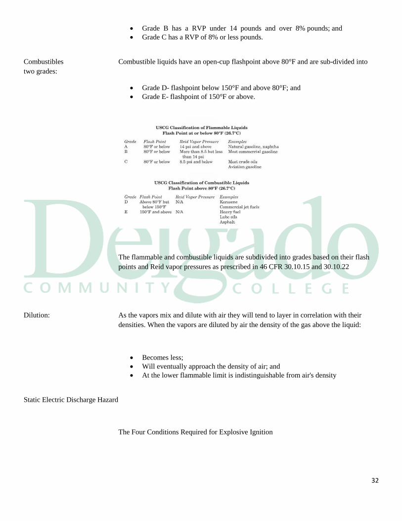
Flammables: Flammable liquids have an open-cup flashpoint at or below 80°F and are sub-divided into
three grades:
Grade A has a RVP of 14 pounds or more;
32
Grade B has a RVP under 14 pounds and over 8% pounds; and
Grade C has a RVP of 8% or less pounds.
Combustibles Combustible liquids have an open-cup flashpoint above 80°F and are sub-divided into
two grades:
Grade D- flashpoint below 150°F and above 80°F; and
Grade E- flashpoint of 150°F or above.
The flammable and combustible liquids are subdivided into grades based on their flash
points and Reid vapor pressures as prescribed in 46 CFR 30.10.15 and 30.10.22
Dilution: As the vapors mix and dilute with air they will tend to layer in correlation with their
densities. When the vapors are diluted by air the density of the gas above the liquid:
Becomes less;
Will eventually approach the density of air; and
At the lower flammable limit is indistinguishable from air's density
Static Electric Discharge Hazard
The Four Conditions Required for Explosive Ignition
33
The clearest description of the required conditions for electrostatic hazard is perhaps in
NFPA 77, which states:
The development of (static) electrical charges may not be in itself a potential fire or
explosion hazard. There must be a discharge or a sudden recombination of separated
positive and negative charges. In order for static to be a source of ignition, four
conditions must be fulfilled:
There must first of all be an effective means of static generation,
There must be a means of accumulating the separate charges and maintaining a
suitable difference of electrical potential,
There must be a spark discharge of adequate energy, and
The spark must occur in an ignitable mixture.
Mechanisms for Producing Hazardous Conditions
Static generation two differing substances in contact with each other will often become
charged as one surrenders electrons to the other. Although the net charge remains
constant, an electrical double layer is formed along the adjoining surfaces. The separation
of the two substances often causes them to remain disparately charged, an effect which is
exaggerated by increased speed of separation and increased mechanical work (friction).
Piping of oil products Charge generation and separation occur when liquids move in
contact with other materials, as in operations involving piping, filtering, mixing or
agitating. Mechanisms which exacerbate static separation in cargo loading operations are
the following:
Turbulence and splashing of the fluid at the beginning of tank loading operations
when the pipe opening is not yet covered with cargo, especially since it is most
likely at this time for water to mix with incoming oil.
Any mixing or filtering of the cargo, particularly micropore or clay filtering.
Impurities such as water, metals, rust, or other product in the cargo.
Disturbance of water "bottom".
Pumping of entrained air or other gases bubbling in the tank.
The cargo is also disturbed during unloading operations, as the fluid moves past hull
structure, piping, etc., particularly during stripping when tank levels are at their lowest.
Discharge of slops and contaminated ballast also generates high amounts of static charge.
34
Displacing of lines using air and water is a static charge generator.
Water mist and steam Mists formed during water washing or from the introduction of
steam can become electrostatically charged. The charge associated with water washing
may be much higher if cleaning chemicals are used.
Steaming produces mist clouds much more highly charged than water washing, much
more quickly, and can also cause the release of gases due to the heat and disturbance of
the process.
Potentials are higher in large tanks than small ones, a fact borne out by several serious
accidents in the early VLCCs.
Loading overall (from the top of the tank) can deliver charged liquid into a tank which
breaks up into small droplets and splashes into the tank. This can produce a charged mist
and an increased hydrocarbon gas concentration.
Air release in bottom of tanks Air or inert gas blown into the bottom of a tank can
generate a strong electrostatic charge by bubbling action and agitation of the fluid.
Crude oil washing (COW) Mixtures of crude oil and water can produce an electrically
charged mist if used for COW operations.
Accumulation of charge and potential
Static accumulator and non-accumulator oils.
35
The conductivity of a liquid determines whether or not it retains the generated static
charge. A non-accumulator oil, defined by an electrical conductivity of greater than 50
(pS/m) [5] will relax quickly because it transmits the charge to the steel hull, which is
grounded in the water. Accumulator oils are defined as having a conductivity of less than
50 pS/m [5]; these oils relax (dissipate charge) slowly.
When accumulator oil is loaded, charges of similar sign repel from each other toward the
liquid's outer surfaces, including that in contact with air. The latter is called the "surface
charge" and is usually of most concern.
ISGOTT states that, in general, black oils do not accumulate static charge and clean oils
(distillates) do. It classifies several oils as follows:
Non-accumulator oils Crude oils
Residual fuel oils
Black diesel oils
Asphalts
Accumulator oils
Natural gasolines
Kerosenes
White spirits
Motor and aviation gasolines
Jet fuels
Naphthas
Heating oils
Clean diesel oils
Lubricating oils

36
Charges which have been separated attempt to recombine and to neutralize each other.
This process is known as charge relaxation. If one, or both, of the separated materials
carrying charge is a very poor electrical conductor, recombination is impeded and the
material retains or accumulates the charge upon it. The period of time for which the
charge is retained is characterized by the relaxation time of the material, which is related
to its conductivity; the lower the conductivity the greater is the relaxation time.
If a material has a comparatively high conductivity, the recombination of charges is very
rapid and can counteract the separation process, and consequently little or no static
electricity accumulates on the material. Such a highly conducting material can only retain
or accumulate charge if it is insulated by means of a poor conductor, and the rate of loss
of charge is then dependent upon the relaxation time of this lesser conducting material.
Discharge: Electrostatic breakdown between any two points, giving rise to a
discharge, is dependent upon the strength of the electrostatic field.
Bonding and Grounding
The most important measure to prevent electrostatic hazard is to bond all metal objects
together, eliminating risk of discharge between objects, and to assure that all components
in the cargo handling system are at the same, electrical potential. Grounding to earth is
not necessarily desirable for all forms of transport; airplanes and tank trucks are insulated
from ground by their tires and may be at a vastly different potential. In the case of tank
vessels, grounding (or earthing) is effectively accomplished by bonding to the hull, which
is naturally earthed through the water. Equipment should be designed to facilitate
bonding and, in particular, to avoid the insulation of any conducting metal.
Bonding of cargo transfer piping Hoses used in terminal transfer operations must
be continuously bonded, and grounded to the hull.
37
It is important to note that cargo transfer piping must be insulated from the land-side
terminal since electrical potential may differ from that of the vessel due to stray current
or cathodic protection of the pier. Insulating flanges, joints, or sleeves are sometimes
used to divide the cargo hoses into electrically isolated halves - onboard and shore side.
Each half is bonded and grounded to its respective base potential.
Static Electricity: Static electricity presents fire and explosion hazards during the handling of petroleum,
and tanker operations. Certain operations can give rise to accumulations of electric
charge which may be released suddenly in electrostatic discharges with sufficient energy
to ignite flammable hydrocarbon gas/air mixtures; there is, of course, no risk of ignition
unless a flammable mixture is present. There are three basic stages leading up to a
potential static hazard: charge separation, charge accumulation and electrostatic
discharge. All three of these stages are necessary for an electrostatic ignition.
Charge separation;
Charge accumulation; and
Electrostatic discharges.
Pumping Oil into Tanks
Petroleum distillates often have electrical conductivities less than 50 pico Siemens/meter
and thus fall into the category of accumulators. Since their conductivities are not
normally known, all distillates must be treated as static accumulators unless they contain
an antistatic additive. During and for some time after entry into the tank a static
accumulator oil may carry sufficient charge to constitute a hazard.
The charge may arise through one or more of several different processes:
Flow of the oil through the pipeline system into the tank. Charge generation is
enhanced if water droplets are suspended in the oil as it flows through the pipes.
Flow through a micro pore filter of the kind used for aircraft jet fuels. These
filters have the ability to charge fuels to a very high level, probably because all
the fuel is brought into intimate contact with the filter surface, where charge
separation occurs.
Turbulence and splashing in the early stages of pumping the oil into an empty
tank.
The settling of water droplets, rust or other particles entering the tank with the oil
or stirred up by it in the tank.
38
The generally accepted method for controlling electrostatic generation in the initial stages
of loading is to restrict the flow rate of the static accumulator oil into the tank until all
splashing and surface turbulence in the tank has ceased. At the commencement of loading
an empty tank the linear velocity in the branch line to each individual cargo tank should
not exceed 1 meter/second. The reasons for such a low rate are twofold:
It is at the beginning of filling a tank that there is the greatest likelihood of water being
mixed with the oil entering the tank. Mixtures of oil and water constitute a most potent
source of static electricity. A low loading rate minimizes the extent of turbulence and
splashing as oil enters the tank; this helps reduce the generation of static electricity and
also reduces the dispersal of any water present, so that it more quickly settles out to the
bottom of the tank where it can lie relatively undisturbed when the loading rate is
subsequently increased.
During subsequent loading, the limitations on flow rate imposed by the design of pipeline
systems, coupled with precautions in the introduction of dipping, ullaging and sampling
equipment and the avoidance of electrically isolated conductors, have proved sufficient to
maintain operational safety. If, however, markedly different pipeline or pumping systems
were to be introduced, enabling higher flow rates or velocities to be achieved, then flow
rate limitations might have to be imposed throughout loading.
Oxygen Deficiency: The oxygen content of the atmosphere in enclosed spaces may be low for several reasons.
The most obvious one is if the space is in an inert condition, and the oxygen has been
displaced by the inert gas. Also, oxygen can be removed by chemical reactions such as
rusting or the hardening of paints or coatings.
As the amount of available oxygen decreases below the normal 21% by volume,
breathing tends to become faster and deeper. Symptoms indicating that an atmosphere is
deficient in oxygen may give inadequate notice of danger. Most persons would fail to
recognize the danger until they were too weak to be able to escape without help. This is
especially so when escape involves the exertion of climbing.
While individuals vary in susceptibility, all will suffer impairment if the oxygen level
falls to 16% by volume.
Exposure to an atmosphere containing less than 10% oxygen content by volume
inevitably causes unconsciousness. The rapidity of onset of unconsciousness increases as
the availability of oxygen diminishes, and death will result unless the victim is removed
to the open air and resuscitated.
39
An atmosphere containing less than 5% oxygen by volume causes immediate
unconsciousness with no warning other than a gasp for air. If resuscitation is delayed for
more than a few minutes, irreversible damage is done to the brain even if life is
subsequently restored.
Entry into oxygen deficient spaces must never be permitted without breathing apparatus
until such spaces have been thoroughly ventilated and test readings indicate an oxygen
level of 21% by volume throughout.
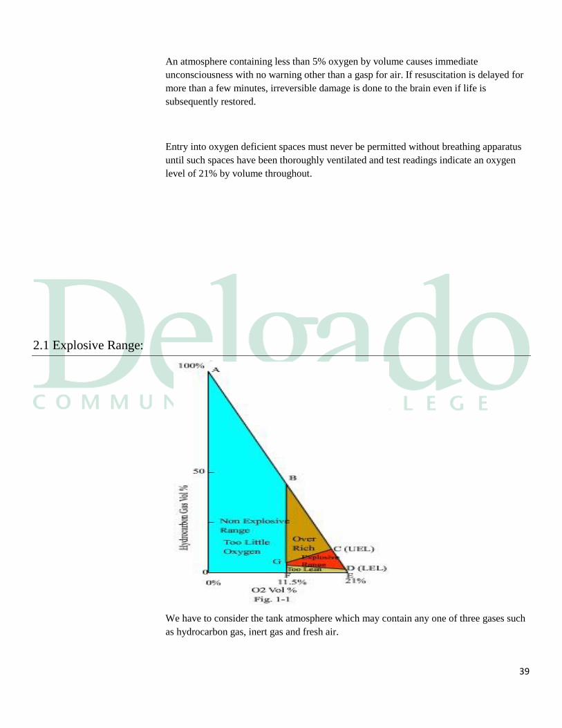
2.1 Explosive Range:
We have to consider the tank atmosphere which may contain any one of three gases such
as hydrocarbon gas, inert gas and fresh air.
40
Then we have to pay attention to hydrocarbon gas and oxygen in fresh air which are
necessary to explosion. As oxygen content in fresh air is approx. 21 % we can draw the
graph shown in Fig. 1-1 which shows hydrocarbon gas with the range from 0% to 100%
in the vertical axis and oxygen content with the range from 0% to 21% in the horizontal
axis.
Point "A" in Fig. 1-1 means the tank atmosphere which consists of 100%
hydrocarbon gas.
Point "O" means the tank atmosphere which consists of 100% inert gas.
Point "E" means the tank atmosphere which consists of 21 % oxygen.
From the above we can consider any kind of tank atmosphere which consists of three
gaseous bodies such as hydrocarbon, inert gas and fresh air according to this Fig. 1-1.
This means, in other words, that the tank atmosphere lies within the triangle AOE.
Explosive Range, UEL and LEL
(Also termed as UFL and LFL):
Under the tank atmosphere which consists of hydrocarbon gas, inert gas and fresh air, the
range of mixture of oxygen and hydrocarbon gas which can be ignited by an external
ignition source is called the "Explosive Range" or "Flammable Range".
Volume percentage of hydrocarbon gas and oxygen are called "Oxygen content" and
"Hydrocarbon gas content".
This explosive range is shown in Fig. 1-1, the area surrounded by points CGD
(Flammable envelope).
The highest point of hydrocarbon and oxygen mixture gas in this area is called the Upper
Explosive Level (UEL) and the lowest point is called the Lower Explosive Level (LEL).
Non-Flammable Range:
In Fig. 1-1 no ignition can occur in the area which is outside the explosive range because
of inadequate mixture of hydrocarbon gas and oxygen. This area is called the "Non-
Flammable Range" or "Non-Explosive Range". This area is shown in Fig. 1-1
A. Too Little Oxygen:
Assuming that the oxygen content is less than the point G (less than 11.5%) no explosion
can occurs even regardless hydrocarbon gas content in a tank. So we call this area
surrounded by points AOFB as Too Little Oxygen condition.
The purpose of I.G.S. installation and the main points of I.G.S. operation is to ensure the
tank atmosphere is in the Too Little Oxygen condition.
B. Over Rich and Too Lean:
Compared with the volume of oxygen, the volume of hydrocarbon gas is too much in the
area surrounded by points BGC and no explosion occurs in this area so referred to as the
Over Rich condition. On the other hand, the area surrounded by points GFED shows that
41
the volume of hydrocarbon gas is too little compared with the volume of oxygen and no
explosion occurs in this area called the Too Lean condition.
How to Use the
Explosive Range Diagram: The tank atmosphere which is not supplied with inert gas is to be considered on the line
AE (Fig. 1-1) and it may come into the explosive range (Line CD). The vessel which is
installed with I.G.S. can keep the tank atmosphere within the Too Little Oxygen
condition by supplying inert gas.
The hydrocarbon composition of crude oil is various between the different grade and
there is only a small variation in their explosion range. Therefore, in order to have the
desired margin of safety, the point UEL is taken as 11.5% by hydrocarbon, LEL is 1.3%
and the point of too little oxygen is 11.5% so we can draw boundary of the explosive
range as shown in Fig. 1-2.
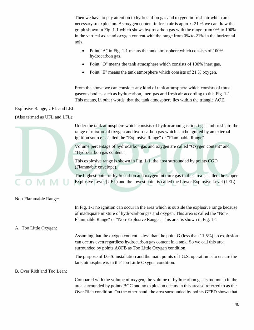
Keep tank atmosphere less than 8% of oxygen content:
Fig. 1-2. Is a magnified view of Fig. 1-1. (Area of hydrocarbon content from 0% to 17%).
When we want to know what the tank atmosphere condition is, we find it out by plotting
oxygen and hydrocarbon content as in Fig. 1-2.
Assuming at the end of tank washing, a cargo tank atmosphere is measured and found to
contain 7% hydrocarbon and 8% oxygen.
Plotted on the Explosive Range Diagram this is point (I). If gas freeing was then carried
out, the hydrocarbon content would decrease and the oxygen content increase, while
passing along line IE.
42
However, on reaching point K on the flammability envelope the tank atmosphere enters
the explosive range and remains in this condition to point L. In order to avoid such a
condition, it is therefore necessary to purge with Inert Gas before gas freeing with air.
Purging the tank atmosphere with good quality Inert Gas will reduce the oxygen content
as well as reducing the hydrocarbon content, passing along line IJ.
Once at J i.e. 2% hydrocarbon and 5% of oxygen, the gas freeing operation can begin and
the addition of air will them keep the tank atmosphere outside the explosive range by
moving along line JE.
If we draw a line from point E to the tangent point of explosive range so we get the line
EM which is called the Critical Dilution Line. Since the tank atmosphere comes below
the Critical Dilution Line there is no possibility of explosion when we supply fresh air
into the tanks.
We must therefore carry out gas freeing after confirmation of the tank atmosphere that it
is below the Critical Dilution Line after measuring the tank oxygen content and
hydrocarbon content.
43
2.2 Sources of Ignition
Smoking: There are frequently local regulations about smoking which must be rigidly observed.
Smoking may be permitted but only under controlled conditions at times and in places
specified by the Master. Personnel when working aboard must not carry matches or more
particularly lighters, and the risk of doing so is to be impressed on all.
Portable Electrical Equipment:
Only approved Safety flashlights are to be used. Portable Electric Equipment self-
contained or on extension cables are not to be used in a gas dangerous place or zone
unless the equipment is intrinsically safe. Portable domestic radios, electronic calculators,
tape recorders and other non-approved battery equipment are not to be used in a gas
dangerous place or zone.
Communication Equipment:
When berthed normal communication equipment is not to be used unless certified safe.
This does not apply to permanently and correctly installed VHF equipment or Satellite
communication systems
Hot Work: Before any hot work, hammering, chipping, or power tools are used the responsible
officer is to examine the area to be worked and satisfy himself that such work can be
safely undertaken and a hot work permit certificate issued. Non - sparking tools are not to
be used as they do not significantly reduce the risk of igniting a flammable vapor.
Shore Bonding: Cargo hoses and loading arms are to be fitted with an insulating flange to ensure
discontinuity between the vessel and shore.
44
Auto - Ignition: The vapors from flammable liquids including fuel and lubricating oil may ignite if the
liquid comes into contact with any surface heated above the auto - ignition temperature
e.g. exhaust manifolds, over heated equipment. Immediate steps are to be taken to rectify
any leakage and to remove any soaked rags on other material including lagging.
Static Electricity: Static Electricity can cause sparks capable of igniting a flammable gas. The cargo system
of a gas carrier is electrically bonded to the ship's hull to prevent any buildup of charges;
bonding connections must be maintained in good order.
2.3 Chemical Data Guide for Bulk Shipment by Water
The number and variety of unconventional liquid cargos being transported in bulk by
water continues to steadily increase. Although the transportation hazards of common
petroleum products are generally well understood, newer commodities often have
unusual fire and explosive properties such as wide flammable range, low ignition
45
temperature and foam incompatibility in addition to other hazards such as toxicity and
dangerous reactivity. It became increasingly evident that a convenient reference guide
listing properties and emergency procedures for bulk liquid cargos was needed by
personnel concerned.
Data sheets are arranged alphabetically by the most commonly-used chemical
name. Following the data pages is a synonym index which shows other names for
the products.
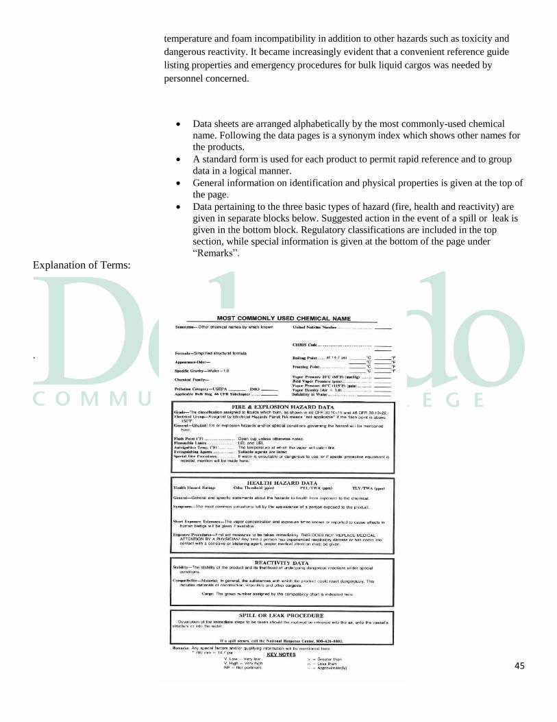
A standard form is used for each product to permit rapid reference and to group
data in a logical manner.
General information on identification and physical properties is given at the top of
the page.
Data pertaining to the three basic types of hazard (fire, health and reactivity) are
given in separate blocks below. Suggested action in the event of a spill or leak is
given in the bottom block. Regulatory classifications are included in the top
section, while special information is given at the bottom of the page under
“Remarks”.
Explanation of Terms:
.
46
Synonyms: Alternate and common names are listed. In general, proprietary and trade names are
not used.
Formula: The constituent elements and a simplified structural formula.
Appearance-Odor: A brief descriptive statement of these properties.
Specific Gravity: This is the ration of the weight of a volume of the cargo to the weight of an equal
volume of water. In the case of liquids of limited solubility, the specific gravity will
predict whether the product will sink or float on water; for example, if the specific
gravity is greater than 1, the product will sink, and if the specific gravity is less than 1,
the product will float.
Chemical Family: A general category which facilitates the use of the compatibility chart (Appendix A) for
predicting the type of reactions which can be expected.
47
Pollution Category is USEPA and IMO In the blanks
Are indicated the category assigned by the EPA for domestic used information,
and the Noxious Liquid Substance (NLS)
Pollution category assigned by the IMO for international Shipment on oceangoing
vessels:
Chemical Data Sheet:
USEPA.X, A, B, C, and D Category associated with reportable quantities of 1,
10, 100, 1000, and 5,000 pounds, respectively. See 40 CFR Table 302.4 (List of
Hazardous Substances and Reportable Quantities).
IMOA, B, C, D NLS category of Annex II of MARPOL 73/78
III Appendix III of Annex III (non-NLS cargos) of MARPOL 73/78. I
Considered an oil under Annex I of MARPOL 73/78.
#No determination of NLS status. For shipping on oceangoing vessels see 46
CFR 153.900 (c).
@The NLS has been assigned by the USCG, in absence of one assigned by the
IMO.
Gas The IMO generally does not assign pollution categories to gases as these
cargos present little to no hazard to the aquatic environment.
Applicable Bulk Registration 46 CFR Subchapter: In the blank is the CFR reference for the carriage of the commodity
United Nations Number: Self-explanatory.
CHRIS Code: The three letter designation assigned to every entry in the Chemical Hazard Response
Information System (CHRIS).
48
2.4 Toxicity and Petroleum
The toxic hazards to which personnel are exposed in transfer operations arise almost
entirely from contact with gases of various kinds.
The toxicity of hydrocarbons is directly related to their physical properties, specifically
the viscosity, volatility, surface tension, and chemical activity of the side chains. The
viscosity is a measure of resistance to flow. Substances with a lower viscosity (e.g.,
turpentine, gasoline, naphtha) are associated with a higher chance of aspiration. The
surface tension is a cohesive force between molecules and is a measure of a liquid's
ability to “creep.” Like the viscosity, the surface tension is also inversely related to
aspiration risk; the lower the viscosity, the higher the risk of aspiration.
Hydrocarbons with a high volatility can vaporize and displace oxygen, which can lead to
a transient state of hypoxia. Not surprisingly, the degree of volatility is directly related
with the risk of aspiration. The amount of hydrocarbon ingested has not consistently been
linked to the degree of aspiration, and hence pulmonary toxicity.
Toxicity from hydrocarbon ingestion can affect many different organs, but the lungs are
the most commonly affected organ. The chemical properties of the individual
hydrocarbon determine the specific toxicity, while the dose and route of ingestion affect
which organs are exposed to the toxicity.
Toxicity from hydrocarbon exposure can be thought of as different syndromes, depending
on which organ system is predominately involved. Organ systems that can be affected by
hydrocarbons include the pulmonary, neurologic, cardiac, gastrointestinal, hepatic, renal,
dermatologic, and hematologic systems.
49
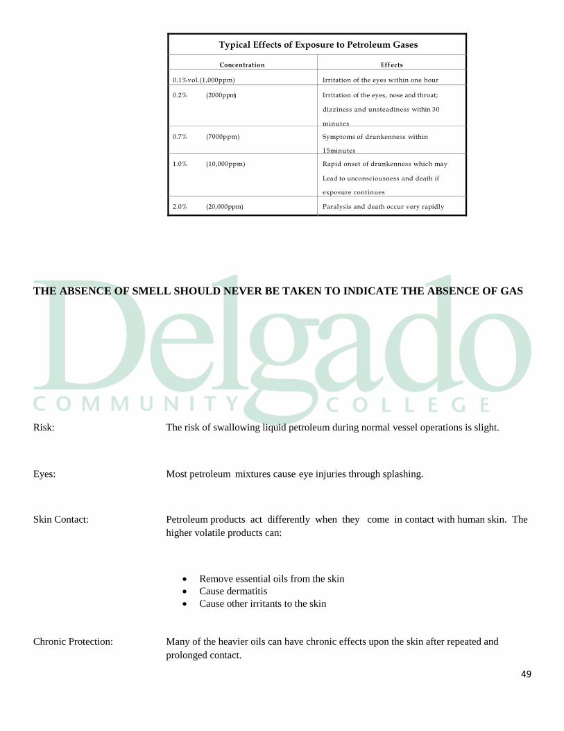
Typical Effects of Exposure to Petroleum Gases
Concentration
Effects
0.1%vol.(1,000ppm)
Irritation of the eyes within one hour
0.2% (2000pp m)
Irritation of the eyes, nose and throat;
dizziness and unsteadiness within 30
minutes
minutes
0.7% (7000ppm) Symptoms of drunkenness within
15minutes
1.0% (10,000ppm)
Rapid onset of drunkenness which may
Lead to unconsciousness and death if
exposure continues
2.0% (20,000ppm)
Paralysis and death occur very rapidly
THE ABSENCE OF SMELL SHOULD NEVER BE TAKEN TO INDICATE THE ABSENCE OF GAS
Risk: The risk of swallowing liquid petroleum during normal vessel operations is slight.
Eyes: Most petroleum mixtures cause eye injuries through splashing.
Skin Contact: Petroleum products act differently when they come in contact with human skin. The
higher volatile products can:
Remove essential oils from the skin
Cause dermatitis
Cause other irritants to the skin
Chronic Protection: Many of the heavier oils can have chronic effects upon the skin after repeated and
prolonged contact.
50
Gas: Direct contact should be avoided by wearing protective equipment when appropriate,
especially gloves and goggles.
Effects: The initial effect that petroleum gas has on a person is a feeling of:
Intoxication
Dizziness
Eye irritation
Headache
Gas Exposure: Exposure to a high concentration of gasses can have an effect on a person as follows:
Paralysis
Unconsciousness
Eventually death
Toxicity: The toxicity of petroleum gasses varies widely depending upon the particular
hydrocarbon compounds contained in them.
Aromatics: The presence of aromatic hydrocarbons in a product present serious hazards to health.
The aromatics are:
Benzene
Toluene
Xylene
Increased Toxins: Minute amounts of the aromatics will increase the toxicity of a petroleum gas
significantly as shown in the greatly reduced threshold limit value for these
hydrocarbons.
Three types of TLVs for
Chemical substances are defined:
51
Threshold limit values are a measure of the relative toxicity of a substance to which a
worker can be exposed without adverse health effects. Expressed as part per million
(ppm), these values represent a maximum value in an atmosphere that should be safe.
TLV-TWA: Threshold Limit Value - Time Weighted Average (TLV-TWA) average exposure on the
basis of a 8h/day, 40h/week work schedule
TLV-STEL: Threshold Limit Value - Short Term Exposure Limit (TLV-STEL) spot exposure for a
duration shorter than 15 minutes that cannot be repeated more than 4 times per day
TLV-C: Threshold Limit Value - Ceiling (TLV-C) absolute exposure limit that should not be
exceeded at any time
Normal TLV: Most cargoes carried in barges have a TLV of about 300ppm and are safe, provided there
are no:
Aromatic hydrocarbons
Hydrogen sulfide
Other toxins present
Test for Toxins: Before you allow entry into a tank that has been blown gas free you must test for the
toxins that were in the product carried. Consult the Material Safety Data Sheet for that
product and you can ascertain:
Which detector tube needs to be used;
What the TLV is for that product; and
If personal protective equipment must be worn.
Benzene: Benzene is an aromatic hydrocarbon seen on barges, either as the cargo itself or as a part
of a product.
Aromatic's TLV: The TLV of aromatic hydrocarbons is much lower than that of other hydrocarbons.
52
Chronic Disease: Exposure to benzene over the TLV leads to chronic disease of the:
Bone marrow
Blood
Benzene Program: Any mariner who carries benzene or a product containing more than 0.5% benzene must
take part in the federal benzene monitoring program, where you are required to:
Have your blood tested annually; and
Your pulmonary function tested every three years.
Hydrogen Sulfide: (H2S) Many crudes have a high concentration of hydrogen sulfide leaving the well and it is so
dangerous that some crudes are stripped off the hydrogen sulfide before being loaded.
Hydrogen sulfide will first kill your sense of smell and then in one hour:
At 50 ppm will irritate the eyes and respiratory tract;
At 200 ppm will markedly irritate eyes and respiratory tract;
At 500 ppm consciousness will be lost after 15 minutes; and
At 700 ppm rapid unconsciousness will occur and death follows a few minutes
later.
2.5 Measurement of Petroleum Cargoes
Introduction: The measurement of oil cargoes is important to the PersonIn-Charge. As the vessel
owner's representative, he is responsible for the accurate gauging of the vessel and for the
accuracy of the subsequent cargo calculations.
Type of Measure: Two types of measurement can be used to determine the level of cargo in a tank:

53
Sounding, which is the distance from the bottom of the tank to the surface of the
liquid; and
Ullage, which is the distance from the measuring point at the top of the tank to
the surface of the liquid.
Unit of Measure: The measurement taken may be in either:
Metric units (meters and centimeters);or
English units (feet and inches).
Development: Over the years different means have been developed to perform these measurements
but must meet §153.404 standards for containment systems having required closed
gauges, and §153.407 special requirements for sounding tube gauges.
Steel Tapes: These tapes are similar to the common measuring tape found in hardware stores and will
be marked in either:
Meters and centimeters
Feet and inches
The Measure: A plumb bob is attached to the end of the tape and lowered into the tank. The
measurement is read off the tape when the bob just touches the surface of the cargo.
Open Gauge: This is very accurate, but the ullage space is open to the atmosphere and can only be done
when open gauging is allowed. The regulations requiring inert gas and vapor emissions
control will eventually cause a phase-out of this method of gauging.
54
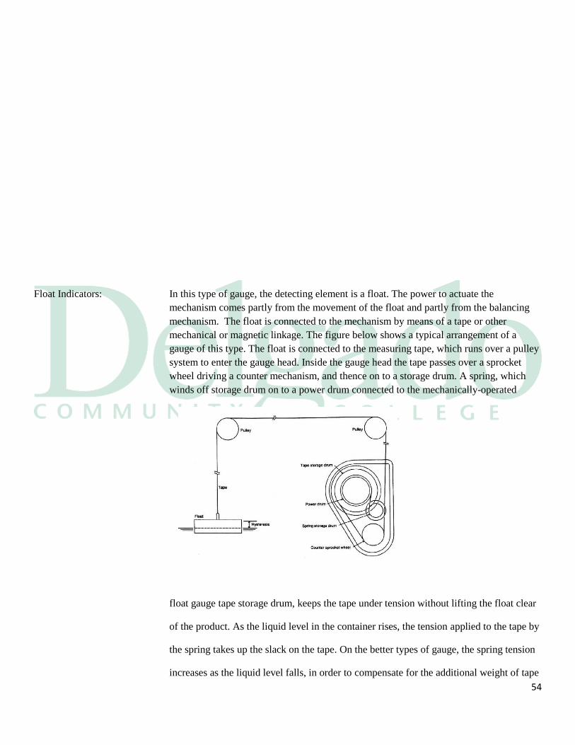
Float Indicators: In this type of gauge, the detecting element is a float. The power to actuate the
mechanism comes partly from the movement of the float and partly from the balancing
mechanism. The float is connected to the mechanism by means of a tape or other
mechanical or magnetic linkage. The figure below shows a typical arrangement of a
gauge of this type. The float is connected to the measuring tape, which runs over a pulley
system to enter the gauge head. Inside the gauge head the tape passes over a sprocket
wheel driving a counter mechanism, and thence on to a storage drum. A spring, which
winds off storage drum on to a power drum connected to the mechanically-operated
float gauge tape storage drum, keeps the tape under tension without lifting the float clear
of the product. As the liquid level in the container rises, the tension applied to the tape by
the spring takes up the slack on the tape. On the better types of gauge, the spring tension
increases as the liquid level falls, in order to compensate for the additional weight of tape
55
used.
Transmits: As the float moves up and down the shaft with the surface of the cargo, it continuously
transmits a signal to remote ullage readout in the cargo control room.
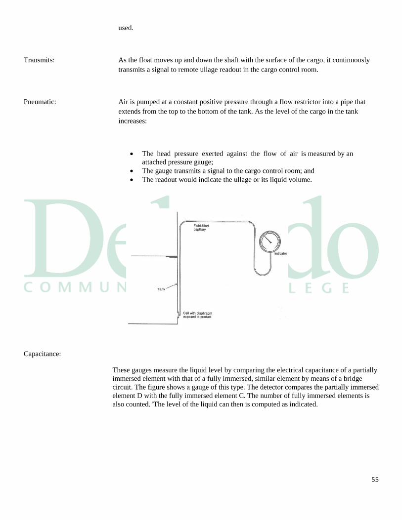
Pneumatic: Air is pumped at a constant positive pressure through a flow restrictor into a pipe that
extends from the top to the bottom of the tank. As the level of the cargo in the tank
increases:
The head pressure exerted against the flow of air is measured by an
attached pressure gauge;
The gauge transmits a signal to the cargo control room; and
The readout would indicate the ullage or its liquid volume.
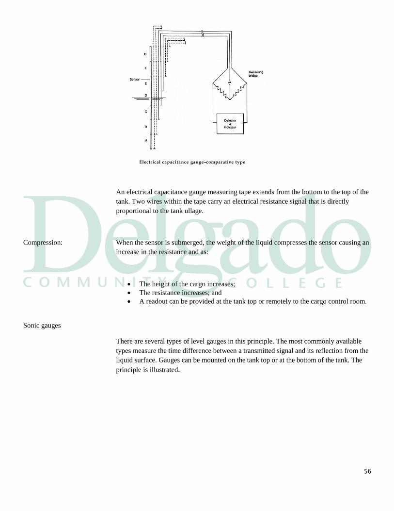
Capacitance:
These gauges measure the liquid level by comparing the electrical capacitance of a partially
immersed element with that of a fully immersed, similar element by means of a bridge
circuit. The figure shows a gauge of this type. The detector compares the partially immersed
element D with the fully immersed element C. The number of fully immersed elements is
also counted. 'The level of the liquid can then is computed as indicated.
56
Electrical capacitance gauge–comparative type
An electrical capacitance gauge measuring tape extends from the bottom to the top of the
tank. Two wires within the tape carry an electrical resistance signal that is directly
proportional to the tank ullage.
Compression: When the sensor is submerged, the weight of the liquid compresses the sensor causing an
increase in the resistance and as:
The height of the cargo increases;
The resistance increases; and
A readout can be provided at the tank top or remotely to the cargo control room.
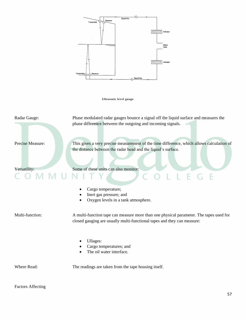
Sonic gauges
There are several types of level gauges in this principle. The most commonly available
types measure the time difference between a transmitted signal and its reflection from the
liquid surface. Gauges can be mounted on the tank top or at the bottom of the tank. The
principle is illustrated.
57
Ultrasonic level gauge
Radar Gauge: Phase modulated radar gauges bounce a signal off the liquid surface and measures the
phase difference between the outgoing and incoming signals.
Precise Measure: This gives a very precise measurement of the time difference, which allows calculation of
the distance between the radar head and the liquid’s surface.
Versatility: Some of these units can also monitor:
Cargo temperature;
Inert gas pressure; and
Oxygen levels in a tank atmosphere.
Multi-function: A multi-function tape can measure more than one physical parameter. The tapes used for
closed gauging are usually multi-functional tapes and they can measure:
Ullages:
Cargo temperatures; and
The oil water interface.
Where Read: The readings are taken from the tape housing itself.
Factors Affecting
58
Accuracy and Repeatability:
The user must be careful not to confuse the terms 'accuracy' and 'repeatability', and
cautious about manufacturers’ claims of accuracy.
Fundamental measuring accuracy is important, but it is less vital to the user than good
repeatability, which is the ability of an instrument to reproduce results under all
conditions. An instrument with good repeatability may have a considerable constant
error, for which allowance can be made. On the other hand, an instrument with very good
statistical accuracy may have poor repeatability; in this case many readings may have to
be taken before any reliance can be placed on the results.
Friction: Friction, the cause of hysteresis in mechanical systems, may increase during the life of a
level gauge owing to corrosion, wear, lack of lubrication, etc. The effects of changes in
friction will be minimized in a well-designed instrument. One must not forget that some
systems also suffer from hysteresis in resolution, although servo-operated gauges are free
from this source of error. (Hysteresis: the lagging of an effect behind its cause, as when
the change in magnetism of a body lags behind changes in the magnetic field.)
Manufacturing tolerances: These are always present in both mechanical and electronic systems; indeed, tolerance
variations of 20% are common in electronic components. Mechanical apparatus and
electronic circuits should be designed to minimize errors from this source. Where
necessary, selected low-tolerance components must be used.
Product density: Changes in product density affect many types of gauge; float gauges will require
correction and capacitance gauges will need to be re-calibrated unless they are of the
comparative type, as will any type using a pressure head. Radioactive gauges are also
affected by density.
2.6 Common Gauging Terms
Calibration Tables: Calibration tables (ullage/innage) are tables developed by recognized industry methods
that represent the volumes in each tank according to the liquid (innage) or empty space
59
(ullage) measured in the tank. The tables are entered with linear measurements (i.e., feet,
meters) to obtain calibrated volumes such as gallons, barrels, cubic meters, or cubic feet.
Reference height is the distance from the tank bottom and/or datum plate to the
established reference point or mark.
Observed reference height is the distance that is actually measured from the tank bottom
or datum plate to the established reference point.
Reference point (gauging point) is the point from which the reference height is
determined and from which the ullages/innages are taken. Historically, most tank vessels
use the rim of the ullage opening in the hatch as the reference point for gauging the tank.
Ullage: Ullage (also referred to as “outage”) is the measured distance from the surface of the
liquid to the above deck reference point or datum. In other words, it is the measurement
of free space above the liquid in a tank
Innage: Innage (also referred to as “dip” or “sounding”) is the measured distance from the surface
of the liquid to a fixed datum plate or to the tank bottom.
Volume: The amount of space occupied by a fluid at certain conditions of temperature and
pressure. Various types of VOLUMES used in marine custody transfer are defined as
follows:
Gross Observed Volume (GOV) - The total volume of all petroleum liquids and
sediment and water, excluding free water, at observed temperature and pressure.
Gross Standard Volume (GSV) - The total volume of all petroleum liquids and
sediment and water, excluding free water, corrected by the appropriate volume
correction factor (VCF) for the observed temperature and API gravity, relative
density, or density to a standard temperature such as 60°F or 15°C and also
corrected by the applicable pressure correction factor (Cpl) and meter factor.
Net Standard Volume (NSV) - The total volume of all petroleum liquids,
60
excluding sediment and water and free water, corrected by the appropriate volume
correction factor (VCF) for the observed temperature and API Gravity, relative
density, or density to a standard temperature such as 60°F or 15°C and also
corrected by the applicable pressure correction factor (Cpl) and meter factor.
On Board Quantity: (OBQ) - The material remaining in vessel tanks, void spaces, and/or pipelines prior to
loading. On-board quantity includes water, oil, slops, oil residue, oil/water emulsions,
sludge, and sediment.
Remaining On Board: (ROB) - The material remaining in vessel tanks, void spaces, and/or pipelines after
discharge. Remaining on board quantity includes water, oil, slops, oil residue, oil/water
emulsions, sludge, and sediment.
Total Calculated Volume: (TCV) - The total volume of all petroleum liquids and sediment and water,
corrected by the appropriate volume correction factor (VCF) for the observed
temperature and API gravity, relative density, or density to a standard temperature such
as 60°F or 15°C and also corrected by the applicable pressure factor (Cpl) and meter
factor, and all free water measured at observed temperature and pressure (gross standard
volume plus free water).
Total Observed Volume: (TOV) - The total measured volume of all petroleum liquids, sediment and water, and
free water at observed temperature and pressure.
Calculations: Once the measurements are taken it is necessary to calculate the following quantities for
each tank:
Gross volume;
Cargo temperature;
Net volume; and
Tons
Gross Volume: The total quantity found by taking the ullage or sounding measurement and looking up
the corresponding quantity in the vessel's ullage tables.
61
Trim Correction: Trim correction will be applied to the measurement before the quantity is determined and
may be stated in terms of:
Barrels;
Cubic meters; or,
Cubic feet.
One Barrel: There is 42 U.S. gallons @ 60º per one barrel of liquid.
Factor: In the English system this is accomplished by using the factors obtained in the API tables
while the metric system uses density.
Multiply Factor: You usually multiply this factor with the gross figure and the result is the net volume at
standard temperature.
Tonnage: The weight of the cargo, expressed as either long tons or metric tons, is determined from
the API tables in the English system or from the density in the metric system.
The API Tables: The API tables are divided into two parts:
Crude oils; and
Generalized petroleum products.
62
Different Tables: Within each part are tables listing API Gravity against specific gravity and density. A
partial listing of the tables barges most commonly use are as follows:
Table 1 the Units of Measurement Conversion;
Table 2 the Temperature Conversions;
Table 3 the API Gravity to Specific Gravity and Density;
Table 6A (crude oils) or 6B (products) the Correction for Volume to 60°F;
Table 8 the Pounds per U.S. Gallon and U.S. Gallons per pound;
Table 11 the Long Tons per 1000 U.S. Gallons and per Barrel; and
Table 13 the Metric Tons per 1000 U.S. Gallons and per Barrel
Reduction: Use the observed temperature and the API gravity of the cargo and enter the volume
reduction table SA or 6B.
Factor: Find the factor to be used to reduce the gross volume to the net volume.
Multiply: Multiply this factor by the gross barrels and the result will be net barrels.
Weight Tables: To calculate the weight of the cargo enter the weight table 11 or 13 with the API gravity
and find the factor to convert from net barrels to tons.
Factor: Multiply this factor by the net barrels to determine the tons.
Example: A vessel has loaded 24,000 barrels of crude oil at a temperature of 78°F with an API of
32.8. What are the net barrels and tons?
Gross barrels: 24,000
Temperature: 78°
API : 32.8
From table 6a: 0.9949
From table 11: 0.13446
24,000 x 0.9949 = 23,877.60 net barrels
23,877.6 x 0.13446 = 3210.58 tons
63
Section 3
Safe Operation
Introduction: Petroleum vessels are inherently hazardous places to work. While we all recognize the
dangers of fire and explosion aboard tank vessels, other dangers are not so readily
apparent to us. The most common cause of injury on barges are:
Slips
Trips
Falls

64
Development: The crew's wellbeing will be enhanced by the development of safe operations on our
vessels by:
Making the crew more aware of the hazards
Standardizing the reporting of hazards
Reporting unsafe operations on the vessels
1978 Report: Annually the Coast Guard's Marine Investigation Division publishes a summary of
commercial vessel casualties of various types. The statistics from the national and
International sources indicate that 85% of accidents are caused by human error. In 1978
there were:
5,606 vessels involved in 3,693 accidents
462 accidents resulted in a total loss
252 of the total losses were fishing vessels
192 lives were lost at sea
Definitions: Dangerous liquid cargoes can be defined as a cargo that:
Is flammable
Is combustible
Poses some danger to human life or health; or
Is designated by the IMO as a marine pollutant
PIC: A Person in Charge can be defined by
The person in charge of a DL transfer;
Has a Tankerman-PIC endorsement on his MMD
Liquefied Gas: A liquefied gas is the liquid form of a substance which, at ambient temperature
and at atmospheric pressure, would be a gas.
65
3.1 Vessel Product Hazards
Hazards: There is a large number of petroleum based products and each can have its own particular
hazard. Dangerous liquids have many traits in common and some of these are that
dangerous liquids are:
Toxic
Asphyxiating
Flammable
Combustible
A pollutant
Toxic Liquids: Dangerous liquids are toxic which means they are poisonous. Toxic effects may be
described as either acute or chronic. Most dangerous liquids are toxic and have both acute
and chronic effects. Some of these products are but not limited to:
Gasoline
Benzene
Naphtha
Crude oil
Acute Effect: Acute as it pertains to dangerous liquids, means the liquid can cause violent illness
coming to crisis speedily. The more acute the liquid is, the time you can be exposed to it
becomes shorter and death becomes the end result. Examples of these liquids are:
Hydrogen sulfide
Aromatic hydrocarbons
Benzene
66
Chronic Effect: Chronic refers to effects that are usually produced over long term exposure to a
dangerous liquid or vapor. Many petroleum based products are carcinogens for long term
exposure.
3.2 Operational Safety
Monitoring: In order to reduce personnel exposure, the Coast Guard has set up a benzene monitoring
program for all vessels that carry products containing 0.5% benzene by volume or more.
This program can be found in 46 CFR 197.500 and consists of:
67
Testing each vessel for hot spots (regulated areas)
Cordoning off the manifold and regulated areas
Displaying warning signs
Crew is fit tested for their respirators
Respirators are worn by crew in regulated areas
Personnel are tested by a physician annually
PPE: Vessel operators should supply the crew with Personal Protection Equipment (PPE) and
disposable suits to reduce their exposure to dangerous liquids. Some of this PPE gear
consists of:
Rubber gloves and boots
Disposable suits
Respirators
Hard hats
Dragger tube monitoring devices
PPE Maintenance All PPE should be inspected and maintained according to manufacture recommendations.
If and PPE is found to be defective in any way it should be taken out of service and
replaced with appropriate approved PPE.
IG Dangers: During tank washing operations, the action of the water going through the nozzles at high
pressure and hitting a steel bulkhead can produce static electricity. IG must be running
into the tanks being washed at all times, keeping:
A positive IG pressure in the tanks; and
The tank atmosphere at or below 8% 02.
Safer: This makes things safer because:
Static electricity can cause no harm; and
The positive pressure produces a better bottom wash.
Skin Contact: The crew must be made aware of the dangers of the products they are carrying and what
to do if their skin comes into contact with the liquid hydrocarbon product during:
68
Hose hook ups
Butterworth operations
Pump room entry
Tank entry
EM Shower: The MSDS sheets for each product are made readily available to the crew and will give
them instructions on what to do if they come into skin contact with the products. They
will also be able to find on deck:
Emergency showers
Eye wash facilities
Fire Prevention: Fire requires a combination of fuel, oxygen and a source of ignition. Most combustible or
flammable substances, only when heated, give off gas vapors which burns if ignited when
mixed with an appropriate quantity of oxygen, as in air.
Fires can be controlled and extinguished by the removal of heat, fuel or air. The main aim
when fighting fires must therefore be to reduce the temperature or to remove the fuel or
to exclude the supply of air with the greatest possible speed.
The three elements that are necessary to produce fire are:
Fuel
Oxygen; and
An ignition source
Industrial Hygiene: Good housekeeping plays an important role in preventing fires other than the cargo deck.
The PIC Tankerman 's Sanitary Inspections should be made to ensure:
The paint locker is secure with all fume sources closed
The engine spaces are cleaned and maintained
Oily rags are properly disposed of
Classes of Fire:
CLASS MATERIAL EXTINGUISHING
METHOD/AGENT
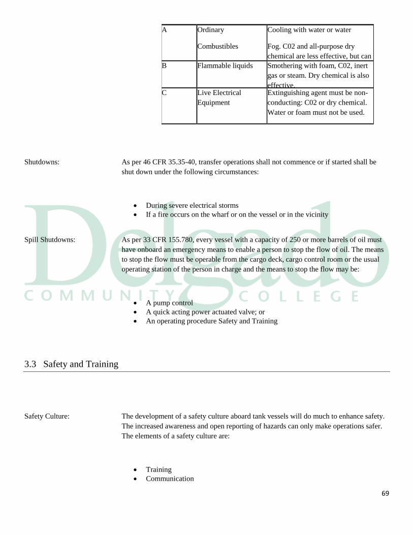
69
A Ordinary
Combustibles
Cooling with water or water
Fog. C02 and all-purpose dry
chemical are less effective, but can
be used. B Flammable liquids Smothering with foam, C02, inert
gas or steam. Dry chemical is also
effective. C Live Electrical
Equipment
Extinguishing agent must be non-
conducting: C02 or dry chemical.
Water or foam must not be used.
Shutdowns: As per 46 CFR 35.35-40, transfer operations shall not commence or if started shall be
shut down under the following circumstances:
During severe electrical storms
If a fire occurs on the wharf or on the vessel or in the vicinity
Spill Shutdowns: As per 33 CFR 155.780, every vessel with a capacity of 250 or more barrels of oil must
have onboard an emergency means to enable a person to stop the flow of oil. The means
to stop the flow must be operable from the cargo deck, cargo control room or the usual
operating station of the person in charge and the means to stop the flow may be:
A pump control
A quick acting power actuated valve; or
An operating procedure Safety and Training
3.3 Safety and Training
Safety Culture: The development of a safety culture aboard tank vessels will do much to enhance safety.
The increased awareness and open reporting of hazards can only make operations safer.
The elements of a safety culture are:
Training
Communication
70
Contingency planning
Situational awareness
Training: Training is formally done:
On board the vessels
Ashore in schools set up for it
At the home office
Documentation: Documentation of successfully completing all the required training is a must with the
implementation of:
The STCW codes
The Coast Guard's Prevention through People
The ISO/ISM code
Sub-Chapter-M
Shore Courses: Ashore seamen will be formally trained and documented in various courses such as:
PIC Dangerous Liquid Cargo
Bridge Team Management
Firefighting
GMDSS
Survival Craft
Vessel Training: Onboard the vessel, training will go on as it always did but it will be documented more
finally. Some of this onboard training is:
Vessel specific orientation
Fire and lifeboat drills
Emergency medical drills
Pollution control drills
Emergency gear drills
Communications: Communications in regard to vessel operations may be divided into the following
communication forms:
71
External
Internal
Written
Verbal
External communications: External communications are generally dealing with persons not of the vessels crew, such
as:
Cargo orders from company
Procedure changes from company
The PIC Tankerman and Pilot conference
The pre-transfer conference
Conferences between the dock and the vessel during the transfer
Internal : Internal communications onboard the vessel can be between:
The cargo team
The bridge team
The emergency squad
The medical emergency team
The normal watches
Information: Communications always involves an exchange of information. This information may be
about:
Current or future operations
The thoughts and ideas of the crew involved
Effective communications: Effective communications occur when the receiver interprets the sender's message the
way it was intended to be understood. Effective communications includes:
Verbal signals
Non-verbal signals
Uncluttered diagrams
Written orders
72
Precise wording
Short sentences
Communications: The ABC's of good communication are
Accuracy
Brevity
Clarity
Situational Awareness and
Error Chains Awareness: Situational awareness is an accurate perception of what is going on around you at all
times. The factors included are conditions that affect:
The vessel
The terminal
The surrounding area
The cargo handling team during the operation
Seaman's Eye: The "Seaman's Eye" is a form of situational awareness. The development of situational
awareness in an individual takes:
Time
Experience
Training
Development: A capable and concerned individual will develop adequate situational awareness much
faster than a person who does not put forth an effort to learn.
Series: Accidents are not caused by a single catastrophic event but are led to the accident by a
series of:
Acts
Events
Omissions

73
Error Chain: A series of actions, which together lead to an accident, is called an error chain. Changing
any of the elements of the series breaks the error chain and the accident will not happen.
Recognition: The recognition of an error chain in development and being able to determine how to
break it is an important part of situational awareness. Some ways to recognize if an error
chain is developing are if:
The checklist to start an operation was not done
Something is out of phase
The pre-calculated conditions do not jibe with reality
Shut down the operation and reassess
74
3.4 Planning and Checklists
Situations: Many vessels have made contingency plans to deal with some or all of the following
situations:
Communications failure
Mooring failure
Inert gas system failure
Hydraulic or control air failure
Enclosed space entry
Enclosed space rescue
Personnel evacuation
A fire or explosion on board the vessel
Checklists: Each of the above contingency plans has its own checklist.
Drills: Drills must be conducted to test a contingency plan. If the plan is not drilled, there is no
way to tell if the contingency plan will work. It is through drills that contingency plans
are refined.
Memory Aids: The effective use of checklists as a memory aid in complicated or stressful operations has
been proven to work well in the aviation community.
75
Examples: The Declaration of Inspection is a very detailed checklist we must complete before
transferring cargo. Some other areas where checklists are required are:
Fire and boat drill
Inspecting lifeboat gear
Inspecting fire equipment
Sending a distress message
Receiving a distress message
SDS: The Safety Data Sheet, required by 46 CFR153.907, for each dangerous liquid product
the vessel is carrying must be readily available to the crew. Most vessels display them in
the:
Bridge
Crew lounge
Galley
Information: These sheets must have the name of the product as listed in Table 1of 46 CFR 153 and
the following information.
IMO category
UN number
Description of the cargo's appearance
Hazards in handling the cargo
Any special handling procedures such as inserting
Procedures to follow if cargo spills or leaks
Procedures for treating a person exposed to the liquid
A list of firefighting procedures and extinguishing agents effective with cargo
fires
Vessel’s name
Loading point
Approximate quantity of cargo
Liquefied Gas: The PIC Tankerman shall ensure that the following information for cargoes listed in 46
CFR 154 are readily available on the vessel:
The name of the cargo listed in table 4 of Part 154
The name of the cargo listed in 46 CFR 30.25-1
The name of a cargo prescribed in the letter authorizing carriage of the cargo
The vessels name for the cargo
The name of the vessel if the cargo is neither hazardous nor flammable

76
77
3.5 Tank Entry
Introduction: Entry into cargo tank spaces is an operational requirement and a frequent operation on
most barges. It can be done safely when all personnel are properly trained, instructed
and follow the appropriate procedures. Entry into cargo tanks and other confined or
remote spaces expose crewmembers to the potential of:
Fire
Explosion
Exposure to toxins
Asphyxiation
Why Enter: It may be necessary to have personnel enter enclosed spaces to:
Inspect
Clean
Conduct repair or maintenance work
Retrieve objects
78
To attempt rescue of co-workers
Training: All vessel board personnel should have training and a working knowledge of the
following:
Recognizing what a confined space is by definition
Identifying what confined space hazards are
Evaluating the hazards once they are identified
Knowing the physical symptoms associated with exposure to hazardous materials
Knowing the control procedures for the space during the time it is occupied
Being prepared for tank rescue
Confined Space: According to the Osha standard 29CFR1910 and The National Fire Protection Agency
Standard 350, these organizations defines a confined space as one that is big enough and
so configured to permit entry and allow work to be done. The confined space is not
designed for continuous human occupation. It has:
Limited or restricted means of entry
Limited or restricted means of exit
It has inadequate natural ventilation
Examples: If you are not sure that a space is a confined space, you must assume it is one and act
accordingly. The following are some examples of vessel board confined spaces.
Cargo and ballast tanks
Peak tanks
Cofferdams
Hazardous Space: A hazardous confined space is one that presents an atmospheric or physical hazard to
human life. The space may cause injury, illness or death because it may contain an
environment that is:
Explosive
Poisonous
Corrosive
Irritating
Asphyxiating
Otherwise harmful
Risk of Entry: A hazardous atmosphere is one that may expose employees to the risk of:
79
Death
Incapacitation
Impairment of ability to self-rescue
Acute illness
Atmosphere: The risk of entry, due to a hazardous atmosphere can be from one or more of the
following causes:
Flammable gas in excess of 10% of its LFL
Airborne combustible dust at a concentration that meets or exceeds its LFL
Atmospheric c oxygen concentration below 19.5% or above 22.0%
Atmospheric concentration of any substance for which the permissible exposure
limit is exceeded
Any other atmospheric condition that is immediately dangerous to life or health
Adjacent Spaces: Atmospheric hazards may not end in the confined space that they originated in.
Explosive, flammable or toxic vapors might migrate and displace the oxygen content in
adjacent spaces such as:
Engineering spaces
Cargo tanks
Storerooms
Living quarters
Physical Hazard: There are three types of physical hazards associated with confined spaces and those are:
Engulfment
Entrapment
Slips, trips and falls
Engulfment: If a person entered a confined space containing grain and the grain shifted that person
might be engulfed by the grain and killed. Engulfment may be by any movable solid or
liquid, which can cause death through:
Suffocation
Constriction
Crushing
80
Trips and Falls: A crewman walking on the bottom of a cargo tank could trip and a fall over the
longitudinal because of
Vessel movement
Poor lighting
Carelessness
02 Absorption: Oxygen deficiency should be suspected in all enclosed spaces. Oxygen depletion by
absorption in a space can take place through several methods such as:
Fermentation of fruit
Decomposition of wood
The oxidation of metal forming iron oxide
02 Excess: There is a hazard in an oxygen enriched atmosphere were the oxygen content exceeds
22.0% oxygen. A confined space can become oxygen enriched through leaks from an
oxygen line.
02 Danger: An atmosphere that is oxygen enriched has the danger of fire and explosion within that
space. Personnel should be restricted or removed from the space until the oxygen content
can be lowered to normal levels.

81
82
3.6 Guidelines for Safe Tank Entry
Introduction: No confined space should be entered before the atmosphere within it has been
comprehensively tested and analyzed. The senior officer present is responsible to ensure
the tank is properly tested in the order given:
Oxygen content
Explosive vapors
Toxic vapors
Meter MSA Altair 4 The ALTAIR 4X is an extremely durable Multigas Detector that
simultaneously measures up to four gases from a wide range of XCell(R) sensor options
including combustible gases, O₂, CO, H₂S, SO₂ and NO₂.
Test Procedure
Bump Test
This is a qualitative function check in which a challenge gas is passed over the sensor(s)
at a concentration and exposure time sufficient to activate all alarm settings. The purpose
of this check is to confirm that gas can get to the sensor(s) and that all the instrument's
alarms are functional. The bump test or function check does not provide a measure of the
instrument's accuracy. When performing a bump test, the challenge gas concentration
should trigger the DRPGM's alarm(s).
Calibration Check or Full Calibration
There are two methods for verifying DRPGM accuracy: a calibration check and a full
calibration. Each method is appropriate under certain conditions.
A calibration check verifies that the sensor(s) and alarms respond within the
manufacturer's acceptable limits by exposing the instrument to a test gas. The operator
83
compares the reading to the test-gas concentration (as indicated on the cylinder
containing the test gas). If the instrument's response is within the acceptable range of the
test-gas concentration (typically ± 10-20% of the test-gas concentration), then the
calibration check verified the instrument's accuracy. (Note: OSHA recommends that
operators check with the instrument's manufacturer for the acceptable tolerance ranges.)
An operator should "zero" an instrument (reset the reference point, in some cases "zero
air" gas may be needed) before conducting the calibration check to ensure that the
calibration check results are accurate. When performing a calibration check, the test-gas
concentration should be high enough to trigger the instrument's alarm(s).
If the calibration-check results are not within the acceptable range, the operator should
perform a full calibration. A full calibration adjusts the instrument's reading to coincide
with a known concentration (i.e., certified standard) of test gas. Test gas used for
calibration gas should always be certified using a standard traceable to the National
Institute of Standards and Technology (NIST).3
When to Perform a Bump Test and / or
When to Perform a Full Calibration
In the past, there has been some confusion regarding proper calibration procedures and
frequency. To clarify this issue, ISEA updated its position statement on instrument
calibration in 2010, stating, "A bump test . . . or calibration check of portable gas
monitors should be conducted before each day's use in accordance with the
manufacturer's instructions." If an instrument fails a bump test or a calibration check, the
operator should perform a full calibration on it before using it. If the instrument fails the
full calibration, the employer should remove it from service. Contact the manufacturer for
assistance or service.
Training: The person using the equipment must have been properly trained in its use and the
equipment must be Coast Guard approved.
Portable Venting: Oxygen samples are taken through the butterworth openings and at various depths
throughout the tank. If the tanks are being ventilated with portable blowers and the
samples are taken from the deck level you should:
84
Stop the ventilation; and
Wait at least 10 minutes to start testing.
IG Fan Venting: If the displacement method of ventilation is being used with the IG fans, the samples
should be taken from the deck level while the fans continue to run. This is done because:
The fan will be running when men are in the tank; and
You want to ensure that no gas is leaking from the inert system.
Still not Safe: Personnel should still not enter the space until it has been tested for a flammable or
explosive atmosphere and for toxic substances.
Hydrocarbon Test: The next test to be conducted, after the oxygen content has been determined, is to test for
hydrocarbon vapors. The testing for the hydrocarbon is done from the deck with
combustible gas indicator and you must ensure that:
The oxygen content is above 14% by volume in the tank;
The testing is done through all openings; and
The testing is done at different levels in the tank.
Explosive Range: The explosive range is considered to be when a flammable vapor of a liquid has mixed
with the proper proportion of air to make an ignitable mixture. The explosive range has a:
Lower explosive limit; and
An upper explosive limit.
Too Lean: The LEL is when there are not enough of the hydrocarbon vapors in the air mixture to
reach the ignition point so that the atmosphere is too lean to burn.
Too Rich: The UEL is when there is too much of the hydrocarbon gas mixed with air in the
atmosphere to ignite so that the atmosphere is too rich to bum.
Static Electricity All equipment that is capable of generating a static charge has to be grounded and bonded
85
Catalytic Sensor: The combustible gas indicator reads up to 100% of the LEL. The sensor works on the
principle of catalytic combustion where a sample of the gas:
Is drawn into the sensor
Where it is burned
This creates an imbalance in the sensing head
This is proportional to the concentration of gasses
Toxicity Test: If the last cargo had benzene or hydrogen sulfide in it, you must test for traces of these
vapors with a toxicity meter. If any hydrogen sulfide is detected entry should be denied
until the vapor is gone. If benzene is detected, entry may be allowed only if it is:
Below the recommended permissible exposure limit
The proper testing was done for benzene
Detector Tubes: Detector tubes are designed to be worn in the space entered to monitor for a specific toxic
agent. They must be easy to use and read. They are operated by:
Breaking the tips off both ends
Drawing a sample of the gas through the detector tube
The reagent in the tube will react with the sample gas
A color stain will develop at the inlet of the detector tube
The gas concentration is measured at the interface
The reagents are sensitive to particular gasses
React to provide a length of stain indication
Calibration Scale: There is a calibration scale on the tube, which is matched against the length of the stain
indication in the tube. This scale will read the parts per million of the gas sampled for, if
found in the atmosphere being tested.
The Goal: The goal is to obtain readings throughout the entire compartment as follows:
Less than 10% of the LEL
21.0% oxygen;
The permissible exposure limits for toxic vapors
86
Supervisor: If the test results are within the proscribed parameters for oxygen, flammability, and
toxicity, preparations for tank entry by an entry supervisor can commence. An entry
supervisor as per 29 CFR 1910.146 can be any of the crew who is:
Suitably trained in the dangers of enclosed space entry
Fully conversant with test procedures
Is trained for the test equipment used for enclosed space entry
Entry Procedure: The tank may still contain pockets of vapors that were not detectable from the deck level.
This will require entry into the space to continue testing the tank as per 46 CFR 153.934.
This requires the following:
The PIC Tankerman 's approval for tank entry
Completion of an enclosed space entry permit
The donning of protective equipment
SCBA worn
A lifeline rigged
A standby crew posted with safety gear
In the Tank: Once you have posted the standby crew the approved person may enter the space. The
person should walk throughout the entire space and check all the nooks and crannies for:
Hidden pockets of hydrocarbon vapor
Deficient oxygen content
Toxic vapors
Damaged ladders and slippery surfaces
Missing or poor lighting
Cargo leaks from an adjacent tank
Leaks from the inert gas system
Cargo residues on the tank surfaces
Tank Passes: If you have reached your goal and the tank has passed, you can begin the task that you
gas freed the tank for. You must:
Issue the proper permits
Continue to ventilate
Constantly monitor the atmosphere
Tank Fails: If you found pockets of hydrocarbons, toxic vapors or deficient oxygen, you will have to:
Wash the tank again
Ventilate until the tank passes inspection
87
Permit Space: According to 29 CFR 1910.146 a permit must be written before anyone can enter a
permit required confined space. These spaces have the following characteristics:
Contains or has the potential to contain a hazardous atmosphere
Contains materials that could engulf an entrant
Has an internal configuration that could entrap an entrant
Contains any other recognized serious safety or health hazard
Entry Permit: The permit is the written or printed document provided or approved by the company to
allow and control entry into an enclosed space after the space is tested for:
Oxygen concentration
Flammable atmosphere
Toxic atmosphere
88
3.7 Safe Tank Entry-Definitions
MSDS: Those that make, distribute, and use hazardous materials are responsible for supplying
Material Safety Data Sheets. These sheets have descriptive data that is concisely outlined
on them. These sheets will identify the material and will give the following information:
IMO and UN numbers
Occupational exposure limits
TWA
STEL
TLV
Physical data
Fire and explosion data
Reactivity data
Health hazard data
PEL: The permissible exposure limit is different for each product. It is the maximum exposure
to a toxic substance that is allowed by the regulatory authorities. PEL's are usually
expressed in:
TWA
STEL
TWA: The time weighted average is the airborne concentrations of a toxic substance averaged
over an 8 hour period and usually expressed as ppm.
STEL: Short term exposure limit is the airborne concentrations of a toxic substance averaged
over any 15 minute period and usually expressed as ppm.
TLV: The threshold limit value is the time weighted average concentration of a substance to
which workers may be repeatedly exposed to, for a normal 8-hour workday or a
40-hour workweek without adverse effect.
89
3.8 Regulations for Confined Space Entry
Introduction: According to 46 CFR 153.934 no person may enter a cargo tank, cargo handling space,
pumproom or enclosed space in the cargo area without the permission of the PIC
Tankerman .
Equipment: Protective equipment would also include equipment found as part of the emergency and
safety equipment under 46 CFR 153.214 such as:
90
Two stretchers or wire baskets for confined space rescue
Equipment for lifting an injured person out of the pumproom or a cargo tank
An approved 30 minute SCBA
5 refills for SCBA
A set of overalls
Boots
Long sleeved gloves
Goggles
A steel-cored lifeline with harness
An explosion proof lamp
A first aid kit
Toxic Testing: As per 46 CFR 153.526 when you are required to test for a specific cargo's toxic vapors,
the vessel must have two toxic vapor detectors, at least one of which must be portable,
with each of them able to:
Measure the vapor concentrations in the range of the TWA for the cargo
The portable detector may be a direct reading detector tube instrument
These detectors may be combined with the flammable vapor detector
Hot Work: As per 46 CFR 35.01-1 the NFPA publication No. 306 shall be used as the guide in
conducting inspections and the issuance of Hot Work Certificates. This publication is
required as part of the vessel board reference materials.
Pre-inspection: As per 46 CFR 35.01-1, until an inspection has been made to determine that such an
operation can be undertaken safely, no alterations, repairs or other such operations
involving riveting, welding, burning or similar fire-producing actions shall be made
within the boundaries of:
The cargo tanks which have been used to carry flammable or
combustible liquid
The spaces adjacent to such cargo tanks
The boundaries of fuel tanks
Pipeline and heating coils
Other appurtenances connected to such cargo or fuel tanks
Marine Chemist: If these inspections are made in the ports, places in the United States or its territories and
possessions, the inspection shall be made by a Marine Chemist certificated by the NFPA
as per 46 CFR 35.01.
91
The Inspection: If the inspection indicates that such operations can be undertaken with safety, a certificate
shall be issued by the Certified Marine Chemist or the authorized person before the work
is started. The certificate shall:
Set forth the fact in writing that hot work is permitted
Qualified as may be required
Qualifications: Such qualifications shall include any requirements as may be deemed necessary to
maintain the safe conditions in the spaces certified, throughout the operation and shall
include:
Additional tests and certifications as required
Precautions necessary to eliminate or minimize hazards that may be present from
protective coatings or residues from cargoes
Outside the USA: When not in such a port or place, as per 46 CFR 35-01-1c2, and a Marine Chemist or
such person authorized by the OCMI is not reasonably available, the inspection shall be
made by the senior officer present and a proper entry shall be made in the vessel's
logbook.
Responsibility: It shall be the responsibility of the senior officer present to:
Secure copies of certificates issued by the Certified Marine Chemist
Maintain a safe condition on the vessel
Fully observe all the qualifications and requirements listed by the Marine
Chemist who wrote the certificate
Length of Permit: Work authorized by the Certificate shall commence within 24 hours unless otherwise
noted on the Certificate providing:
92
The condition of the vessel remains unchanged
The qualifications remain the same
Open Tanks: According to 46 CFR 35.30-10, no cargo tank hatch, or Butterworth plates shall be
opened or shall remain open unless:
The flame screens are in place
It is under the supervision of the senior members of the crew on duty
The tank opened is gas free
Open Covers: The requirements as set forth in 29 CFR 1910.146 require that any conditions making it
unsafe to remove an entrance cover shall be eliminated before the cover is removed.
When entrance covers are removed the opening shall be promptly guarded by:
A railing
A temporary cover
A temporary barrier that will prevent an accidental fall through the opening
3.9 Marine Chemist's Certificates
Introduction: The Marine Chemist shall personally determine the vessel's conditions and he shall be
permitted to issue a Certificate in writing that the prescribed work to a vessel can be
undertaken safely.
Visual Test: The Marine Chemist shall, whenever possible, physically enter each compartment or
space and conduct visual inspections to the extent necessary to determine the atmospheric
or fire hazards that exist.
93
Actual Tests: The Marine Chemist shall carryout tests within each compartment or space, ensuring
compliance with the minimum applicable requirements prior to issuing a Certificate.
Prior to Issue: The Marine Chemist's determinations shall include a visual inspection and tests of the
spaces to be certified and the spaces adjacent thereto. The determinations shall include:
The three previous cargoes
The nature and extent of the work
Starting time and duration of the work
Tests of cargo and vent lines at the manifold and accessible openings
Verification of the pipelines that could release hazardous materials into the work
space have been blanked off or blocked off in a positive manner
Tests of the heating coils
Writing the Certificate: When the Marine Chemist is satisfied that the related requirements necessary for the safe
conduct of the work have or have not been met, a Certificate shall be prepared and the
Certificate shall include:
The frequency and type of additional tests, inspections or other qualifications the
Marine Chemist specifies
The conditions under which the Chemist is to be consulted or recalled
Controls, qualifications and requirements, including PPE and devices to
eliminate or minimize hazards and of limits to where the crew can work
The instrument test results of the Marine Chemist's inspections and tests
Issuance: The Certificate shall be completed and a signature for receipt of the Certificate shall be
obtained from the vessel's PIC, signifying the understanding of the conditions and
limitations under which it was issued.
Additions: Any additions to or deletions from an issued Certificate after obtaining a signature for
receipt shall render the Certificate invalid and require re-issuance.
94
Safe for Workers: The standard safety designation Safe for Workers as per NFPA No 306 and 29 CFR
1910.146 requires that the compartment or space so designated the following criteria
shall be met:
The oxygen content of the atmosphere shall be at least 19.5% and not greater
than 22% by volume
The concentration of flammable materials shall be below 10% of the lower
explosive limit
Any toxic materials in the atmosphere shall be within permissible concentrations
at the time of inspection
The residues or materials associated with the work authorized shall not be
capable of producing uncontrolled toxic materials under existing atmospheric
conditions
Control Measures: Once the Certificate has been issued and the proper control measures have been put into
place, men can enter the space. Some of these controls may be as follows:
IG. Or cargo lock-out, tag-out
Forced ventilation
Staging of rescue equipment
Placement of a SCBA at the tank top
Placement of SCBA within the tank
Proper protective clothing must be worn
Issuance of emergency escape breathing devices
Personnel entry/exit time log is kept
No Hot Work: The space can now be considered safe for workers but the space is not safe for hot work.
95
Periodic Testing: The atmosphere within the space shall be periodically tested as necessary to ensure that
the continuous forced air ventilation is preventing the accumulation of a hazardous
atmosphere. If a hazardous atmosphere is detected you must:
Have each worker leave the space immediately
Evaluate the space to determine how the hazardous atmosphere developed
Measures shall be implemented to protect employees from the hazardous
atmosphere before any subsequent entry takes place
Hot Work Defined: You are doing hot work when you are making alterations, repairs, or other such
operations and you are involved with:
Riveting
Welding
Burning
Grinding
Drilling
Any other operation that may cause a spark or other like fire-producing actions
Testing: The Marine Chemist shall carryout tests within each compartment or space,
ensuring compliance with the minimum applicable requirements prior to issuing a Safe
for Hot Work Certificate.
Procedures: The Certified Marine Chemist would follow the same procedures for a Hot Work
Certificate as he would for any other Certificate. The only difference is the safe criteria to
allow hot work in a compartment or space.
Criteria: The Safe for Hot Work Certificate as per NFPA No 306 and 46 CFR 35.01 requires that
in the compartment or space so designated the following criteria shall be met:
The oxygen content of the atmosphere shall not exceed 22% by volume;
The concentration of flammable materials shall be below 10% of the lower
explosive limit
The residues, scale or materials shall be cleaned sufficiently to prevent the spread
of fire and shall not be capable of producing a higher concentration than
permitted under existing atmospheric conditions
All adjacent spaces, containing or having contained flammable or combustible
material shall be sufficiently cleaned of residues and scale to prevent the spread
of fire or shall be inerted.
96
Not Safe: If any of the above conditions are not met, the designation Not Safe for Hot Work shall
be used.
Chemist Options: The Marine Chemist has latitude with the adjacent space criteria and the hot work area.
Whatever his decision is, it must be:
Considered safe
He must put it in writing on the certificate
Firewatch: Immediately before hot work is started the officer responsible for safety precautions
should examine the area where hot work is to be undertaken. The following steps should
be taken to help ensure safety:
Fire-fighting equipment laid out and be ready for immediate use
Fire watch posted at hot work sight
Fire watch posted in adjacent space where heat could be a factor
Monitoring of the area should be continued for sufficient time after completion of
hot work
Welding Machine: Welding and other equipment employed should be carefully inspected before each
occasion of use to ensure it is in good condition as per NFPA No 306 and 46 CFR 35.01.
Where required it must be correctly grounded. Special attention must be paid when you
are using electric equipment ensuring that:
The electrical supply connections are made in a gas free space
The existing supply wiring is adequate to carry the electrical current demanded
without overloading
The insulation of flexible electric cables laid across the deck is in good condition
The cable route to the work site is the safest possible, only passing over gas free
or inerted spaces
The grounding connection is adjacent to the work site with the earth return cable
led directly back to the welding machine
97
3.10 Emergency Procedure Tank Rescue
Introduction: Most fatalities in enclosed spaces have resulted from individuals entering the space
without proper supervision or adhering to agreed upon procedures. Of those killed in
confined spaces due to atmospheric conditions:
40% were the original victims entering into the space
60% were their would-be rescuers
Fatalities: There have been a great deal of fatalities due to the reaction of would be rescuers coming
to the aid of their friends and becoming victims themselves. This initial reaction to
attempt a rescue may cause one crewman after another to become victims in their
attempts to rescue each other.
Rescue: If you were on deck and noticed a shipmate at the bottom of a tank apparently
unconscious, the following should take place:
The alarm raised
Check tank atmosphere
Ventilation to tank is checked
The person reporting the emergency correctly states the location, nature of
emergency and number of casualties involved
The emergency squad is mustered
The communication signals are reviewed
The hoisting equipment is rigged
Two persons enter the tank with a litter and SCBA's if required
All persons entering and leaving tank are recorded
The victim in the tank is put into the litter
The victim is carefully hoisted from tank
Commence immediate resuscitation treatment if required
The emergency squad thoroughly searches tank for other casualties, unless all
men are accounted for
98
All the emergency equipment is re-stowed and ready for immediate use.
Section 4
Pollution Regulations
Introduction: For the most part, International and U.S. regulations are identical, with a few minor
differences. In some cases the U.S. regulations are more stringent than the IMO rule. In
those cases all vessels in U.S. waters must:
Follow the more stringent U.S. regulation; except
In specific instances where the CFR states that vessels following MARPOL are
exempt, such as 33 CFR 157.12.
MARPOL 73-78: As mentioned earlier in this course the International Regulations that govern vessel
operations in regard to pollution prevention are contained in MARPOL 73/78. The
annexes we are concerned with are:
Annex I, covering pollution by oil
Annex II, covering pollution by NLS
Annex IV, containing the sewage regulations
Annex V, referring to garbage
99
Regulations: OPA 90 and the Clean Water Act of 1970 as amended are the principal governing U.S.
laws for water pollution. Some of OPA 90's changes are:
Established work hours for crew members
Established in port bottom clearances for single hulled barges as in 33 CFR
157.455
All barges plying U.S. waters will be double hull by 2015
Subchapter 0: Subchapter 0 Pollution in 33 CFR contains the majority of U.S. National laws as well as
the international laws found in MARPOL 73/78. Some of these rules are as follows:
Part 151, vessels carrying oil, NLS, garbage, municipal or commercial waste and
ballast water
Part 153, the control of pollution by oil and hazardous substances, discharge
removal
Part 155, oil or hazardous material pollution prevention regulations for vessels
Part 156, oil and hazardous material transfer operations
Part 157, the rules for the protections of the marine environment relating to tank
vessels carrying oil in bulk
Part 159, marine sanitation devices
Regulations: In Subchapter 0 of 46 CFR you will find the rules for certain bulk dangerous cargoes. We
are interested in:
Part 150, compatibility of cargoes
Part 153, vessels carrying bulk liquid, liquefied gas or compressed gas hazardous
materials
Part 154, the safety standards for self-propelled vessels carrying bulk liquefied
gases
Discharge: Discharge is defined by 33 CFR 151.05 as any release, however caused, from a vessel
and includes any:
Escape
Disposal
Spilling

100
Leaking
Pumping
Emitting
Emptying
Marpol: MARPOL differs only slightly with the CFR definition of discharge. MARPOL defines
discharge as related to harmful substances or effluent containing such substances, means
any release, however caused from a vessel, and includes any:
Escape
Disposal
Spilling
Leaking
Pumping
Emitting
Emptying
101
4.1 DOI
__________________________________________________________________________________________________
Declaration of Inspection
After an inspection under 35.3520, but before a transfer of cargo, fuel oil, or bunkers may
commence as described in this section and 33 CFR 156.120 and 156.150, the person in
charge of the transfer shall prepare, in duplicate, a Declaration of Inspection. The original
must be kept aboard the vessel, and the duplicate provided to the terminal supervisor or
that person's representative. The supervisor or the representative may, upon demand,
inspect the vessel to determine whether its condition is as stated on the Declaration of
Inspection.
102
The Declaration of Inspection may be in any form, but must contain at least: Declaration
of Inspection Before Transfer of Liquid Cargo in Bulk Date____________________
Vessel____________________ Port of____________________ Product[s] being
transferred(Classification[s] and Kind[s]) ____________________
The person in charge of the transfer of liquid cargo in bulk about to begin, do certify that
I have personally inspected this vessel with reference to the following requirements set
forth in 46 CFR 35.3520, and that opposite each of the applicable items listed below I
have indicated whether the vessel complies with all pertinent regulations.
Are warnings displayed as required?
Is there any repair work in way of cargo spaces being carried on for which
permission has not been given?
Have cargo connections been made as described in 46 CFR 35.3515 and are cargo
valves set?
Have all cargo connections been made to the vessel's pipeline and not through an
open-end hose led through a hatch?
Are there any fires or open flames present on the deck or in any compartment
which is located on, open or adjacent to or facing the main deck of the vessels on
which the cargo connections have been made?
Has the shore terminal or other tank vessel concerned reported itself in readiness
for transfer of cargo?
Are sea valves connected to the cargo piping system closed?
If Grades, A, B, or C cargoes are to be loaded and boiler fires are lighted, has an
inspection been made to determine whether these fires may be maintained with
reasonable safety?
If Grades A, B, or C cargoes are to be loaded and galley fires are lighted, has an
inspection been made to determine whether the galley fires may be maintained
with reasonable safety?
If Grades A, B, or C cargoes are to be loaded, has an inspection been made to
determine whether smoking is to be permitted in areas not on the weather decks?
4.2 Oil Record Book:
___________________________________________________________________________________________
MARPOL 74/78 ANNEX I REVISED, REGULATION 36 (OIL RECORD BOOK, PART II - CARGO/BALLAST
OPERATIONS)
103
Every oil tanker of 150 gross tonnage and above shall be provided with an Oil Record
Book Part II (Cargo/Ballast Operations). The Oil Record Book Part II, whether as a part
of the ship's official logbook or otherwise, shall be in the Form specified in appendix III
to this Annex.
The Oil Record Book Part II shall be completed on each occasion, on a
tank-to-tank basis if appropriate, whenever any of the following cargo/ballast operations
take place in the ship:
loading of oil cargo;
internal transfer of oil cargo during voyage;
unloading of oil cargo;
ballasting of cargo tanks and dedicated clean ballast tanks;
cleaning of cargo tanks including crude oil washing;
discharge of ballast except from segregated ballast tanks;
discharge of water from slop tanks;
closing of all applicable valves or similar devices after slop tank discharge
operations;
closing of valves necessary for isolation of dedicated clean ballast tanks from
cargo and stripping lines after slop tank discharge operations; and
disposal of residues.
For oil tankers referred to in regulation 34.6 of Annex I (< 150 GT), the total quantity of
oil and water used for washing and returned to a storage tank shall be recorded in the Oil
Record Book Part II.
In the event of such discharge of oil or oily mixture as a result of accidental or other
exceptional discharge of oil not excepted by that regulation, a statement shall be made in
the Oil Record Book Part II of the circumstances of, and the reasons for, the discharge.
Each operation described in this regulation shall be fully recorded without delay in the
Oil Record Book Part II so that all entries in the book appropriate to that operation are
completed. Each completed operation shall be signed by the officer or officers in charge
of the operations concerned and each completed page shall be signed by the master of
ship. The entries in the Oil Record Book Part II shall be at least in English, French or
Spanish. Where entries in an official language of the State whose flag the ship is entitled
to fly are also used, this shall prevail in case of dispute or discrepancy.
104
Any failure of the oil discharge monitoring and control system shall be noted in the Oil
Record Book Part II.
The Oil Record Book shall be kept in such a place as to be readily available for
inspection at all reasonable times and, except in the case of unmanned ships under tow,
shall be kept on board the ship. It shall be preserved for a period of three years after the
last entry has been made.
4.3 Air Pollution
_________________________________________________________ ______________________________
This is a matter of growing international concern. Rules to control air pollution are
included in Annex VI to MARPOL. Students should be aware that there may be local or
national rules which must be complied with.
No international regime to control air pollution from ships applies today, although strict
national rules apply in some ports. Air pollution from oil tanker operations may be
caused by the loading and ballasting of tanks, as these operations result in inert gas and
hydrocarbon gas being vented to the outside atmosphere.
Another operation resulting in air pollution is gas-freeing. If local regulations limit air
pollution, special measures must be taken. These can take two forms, a vapor-return line
or gas-vapor displacement. Vapor return entails transferring all gas displaced from cargo
tanks to the installation ashore, this requires special provisions that are not normally
found on oil vessels.
Gas-vapor displacement is not always possible. If a vessel is being discharged and cargo
tanks are being ballasted, it is possible to contain the gas-vapor. In this case the venting
system is closed to the outside atmosphere and the inert gas will be driven from the tanks
being ballasted to those being discharged. The supply of inert gas must be adjusted to
keep a slight positive pressure in the tanks.

105
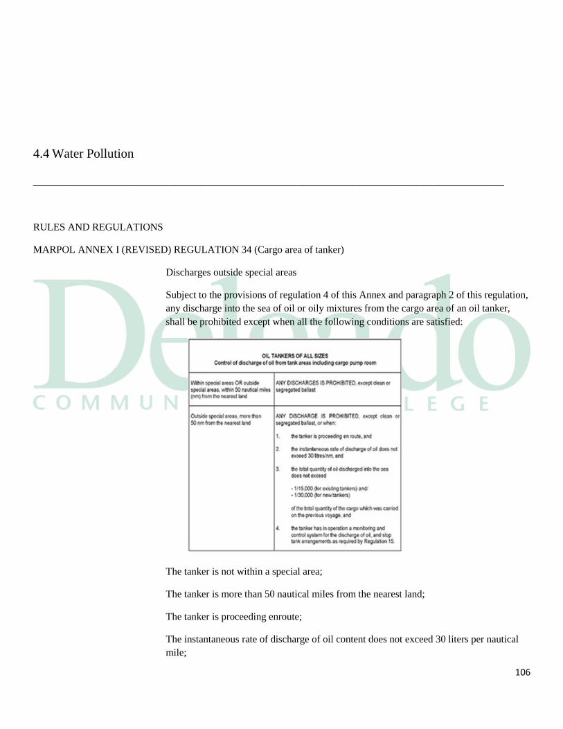
106
4.4 Water Pollution
_________________________________________________________________________
RULES AND REGULATIONS
MARPOL ANNEX I (REVISED) REGULATION 34 (Cargo area of tanker)
Discharges outside special areas
Subject to the provisions of regulation 4 of this Annex and paragraph 2 of this regulation,
any discharge into the sea of oil or oily mixtures from the cargo area of an oil tanker,
shall be prohibited except when all the following conditions are satisfied:
The tanker is not within a special area;
The tanker is more than 50 nautical miles from the nearest land;
The tanker is proceeding enroute;
The instantaneous rate of discharge of oil content does not exceed 30 liters per nautical
mile;
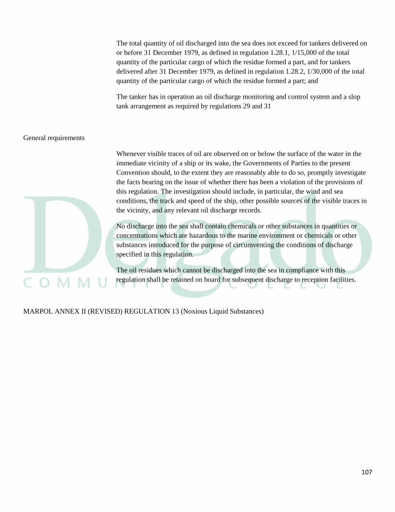
107
The total quantity of oil discharged into the sea does not exceed for tankers delivered on
or before 31 December 1979, as defined in regulation 1.28.1, 1/15,000 of the total
quantity of the particular cargo of which the residue formed a part, and for tankers
delivered after 31 December 1979, as defined in regulation 1.28.2, 1/30,000 of the total
quantity of the particular cargo of which the residue formed a part; and
The tanker has in operation an oil discharge monitoring and control system and a slop
tank arrangement as required by regulations 29 and 31
General requirements
Whenever visible traces of oil are observed on or below the surface of the water in the
immediate vicinity of a ship or its wake, the Governments of Parties to the present
Convention should, to the extent they are reasonably able to do so, promptly investigate
the facts bearing on the issue of whether there has been a violation of the provisions of
this regulation. The investigation should include, in particular, the wind and sea
conditions, the track and speed of the ship, other possible sources of the visible traces in
the vicinity, and any relevant oil discharge records.
No discharge into the sea shall contain chemicals or other substances in quantities or
concentrations which are hazardous to the marine environment or chemicals or other
substances introduced for the purpose of circumventing the conditions of discharge
specified in this regulation.
The oil residues which cannot be discharged into the sea in compliance with this
regulation shall be retained on board for subsequent discharge to reception facilities.
MARPOL ANNEX II (REVISED) REGULATION 13 (Noxious Liquid Substances)
108
Discharge standards
Where the provisions in this regulation allow the discharge into the sea of residues of
substances in Category X, Y or Z or of those provisionally assessed as such or ballast
water, tank washings or other mixtures containing such substances the following
discharge standards shall apply:
The ship is proceeding enroute at a speed of at least 7 knots in the case of self-propelled
ships or at least 4 knots in the case of ships which are not self-propelled;
The discharge is made below the waterline through the underwater discharge outlet(s) not
exceeding the maximum rate for which the underwater discharge outlet(s) is (are)
designed; and
The discharge is made at a distance of not less than 12 nautical miles from the nearest
land in a depth of water of not less than 25 meters.
109
Section 5
System Components, Pump Designs & Instruments
Introduction: There are several piping systems to be found onboard tankers:
Cargo systems Inert gas Vapor emissions Water in the firemain Water in the foam main
Each piping system has its own purpose and was designed to meet the needs of the
system it serves. Each system was designed regarding the expected operating pressures
and vacuums. Safety factors are designed such that the pipes will:
Be stronger than needed for their designed use
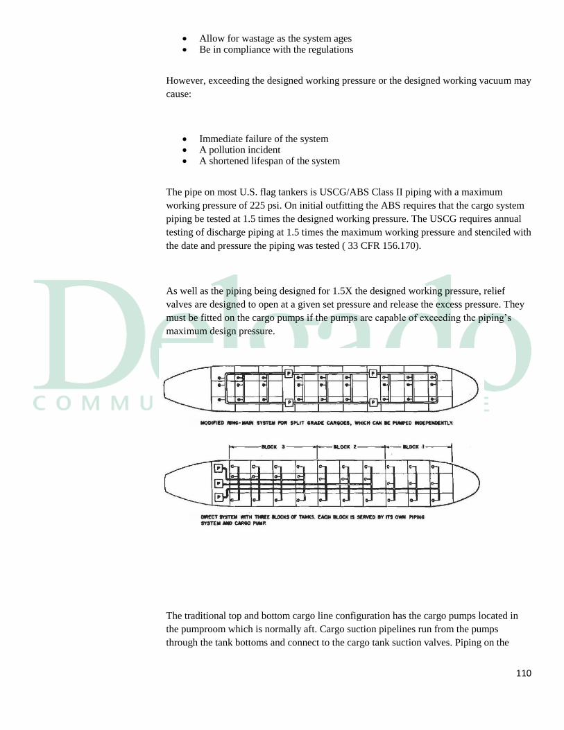
110
Allow for wastage as the system ages Be in compliance with the regulations
However, exceeding the designed working pressure or the designed working vacuum may
cause:
Immediate failure of the system A pollution incident A shortened lifespan of the system
The pipe on most U.S. flag tankers is USCG/ABS Class II piping with a maximum
working pressure of 225 psi. On initial outfitting the ABS requires that the cargo system
piping be tested at 1.5 times the designed working pressure. The USCG requires annual
testing of discharge piping at 1.5 times the maximum working pressure and stenciled with
the date and pressure the piping was tested ( 33 CFR 156.170).
As well as the piping being designed for 1.5X the designed working pressure, relief
valves are designed to open at a given set pressure and release the excess pressure. They
must be fitted on the cargo pumps if the pumps are capable of exceeding the piping’s
maximum design pressure.
The traditional top and bottom cargo line configuration has the cargo pumps located in
the pumproom which is normally aft. Cargo suction pipelines run from the pumps
through the tank bottoms and connect to the cargo tank suction valves. Piping on the
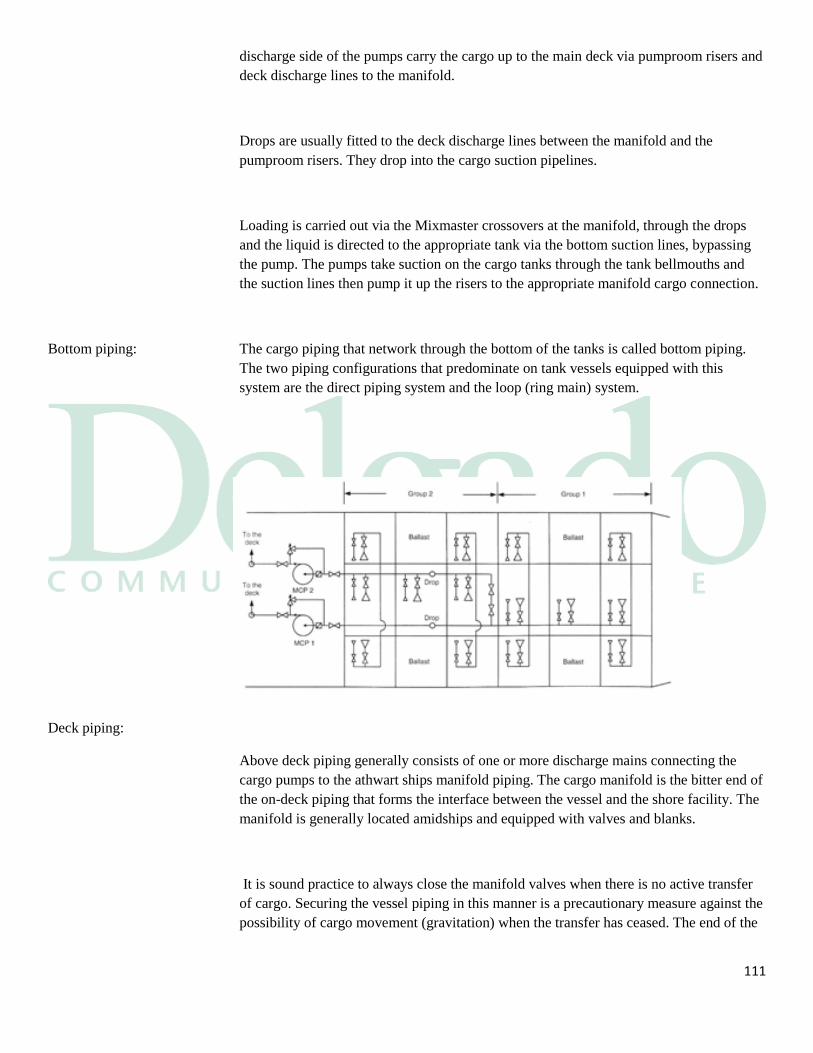
111
discharge side of the pumps carry the cargo up to the main deck via pumproom risers and
deck discharge lines to the manifold.
Drops are usually fitted to the deck discharge lines between the manifold and the
pumproom risers. They drop into the cargo suction pipelines.
Loading is carried out via the Mixmaster crossovers at the manifold, through the drops
and the liquid is directed to the appropriate tank via the bottom suction lines, bypassing
the pump. The pumps take suction on the cargo tanks through the tank bellmouths and
the suction lines then pump it up the risers to the appropriate manifold cargo connection.
Bottom piping: The cargo piping that network through the bottom of the tanks is called bottom piping.
The two piping configurations that predominate on tank vessels equipped with this
system are the direct piping system and the loop (ring main) system.
Deck piping:
Above deck piping generally consists of one or more discharge mains connecting the
cargo pumps to the athwart ships manifold piping. The cargo manifold is the bitter end of
the on-deck piping that forms the interface between the vessel and the shore facility. The
manifold is generally located amidships and equipped with valves and blanks.
It is sound practice to always close the manifold valves when there is no active transfer
of cargo. Securing the vessel piping in this manner is a precautionary measure against the
possibility of cargo movement (gravitation) when the transfer has ceased. The end of the
112
manifold is flanged to permit connection to the shore facility via flexible cargo hoses or
mechanical arms.
Hydraulic Pipe There is a hydraulic piping system on vessels with hydraulic:
Deep well pumps
Mooring winches;
Cranes and davits
Exceeding DWP Exceeding the designed working pressure or the designed working vacuum may cause:
Immediate failure of the system
A pollution incident
A shortened lifespan of the system
Annual Test The USCG requires annual testing of discharge piping at 1.5 times the maximum working
pressure and stenciled with the date and pressure the piping was tested at as per 33 CFR
156.170.
Relief Valves Relief valves are valves designed to open at a given set pressure and release that excess
pressure and they must be fitted on the cargo pumps if the pumps are capable of
exceeding the piping's maximum design pressure.
Hoses Cargo hoses are designed to withstand the cargo pump relief valve setting, less static
head, but never less than 150 psi as 33 CFR 154.500.
Traditional The traditional top and bottom cargo line configuration has the cargo pumps located in
the pumproom which is usually aft.
Suction Lines Cargo suction pipelines run from the pumps through the tank bottoms and connect to the
cargo tank suction valves.
113
Discharge Lines Piping on the discharge side of the pumps carry the cargo up to the main deck via:
The pumproom risers;
The deck discharge lines; to
The manifold.
Drops The drops are usually fitted to the deck discharge lines between the manifold and the
pumproom risers. They drop into the cargo suction pipelines.
Loading Loading is carried out via the mix crossovers at the manifold, through the drops and the
liquid is directed to the appropriate tank via the bottom suction lines, bypassing the
pumproom.
Discharging The pumps take suction on the cargo tanks through the tank bellmouths and the suction
lines then pump it up the risers to the appropriate manifold cargo connection.
Flanges When connections are made using bolted flanges, the following requirements must be
met:
Suitable gasket material must be used in the joints and couplings to make a leak-
free seal. It is not advisable to double up on gaskets or to reuse them. Gaskets are
generally constructed of a fiber or neoprene material; however, Teflon may be
used in certain cargos.
• When ANSI flanges are employed, a bolt must be
placed in every other hole at a minimum, and in no
case should less than four bolts be used in the
connection. Be aware that company policy usually
specifies that a bolt be installed in every hole.
• When using non-ANSI flanges, a bolt must be placed in every hole.
• For permanently connected flanges, a bolt must be placed in every hole.
• Each nut and bolt should be uniformly tightened
to distribute the load and ensure a leak-free seal.
Any bolt exhibiting signs of strain, elongation, or
deterioration should be removed from service.
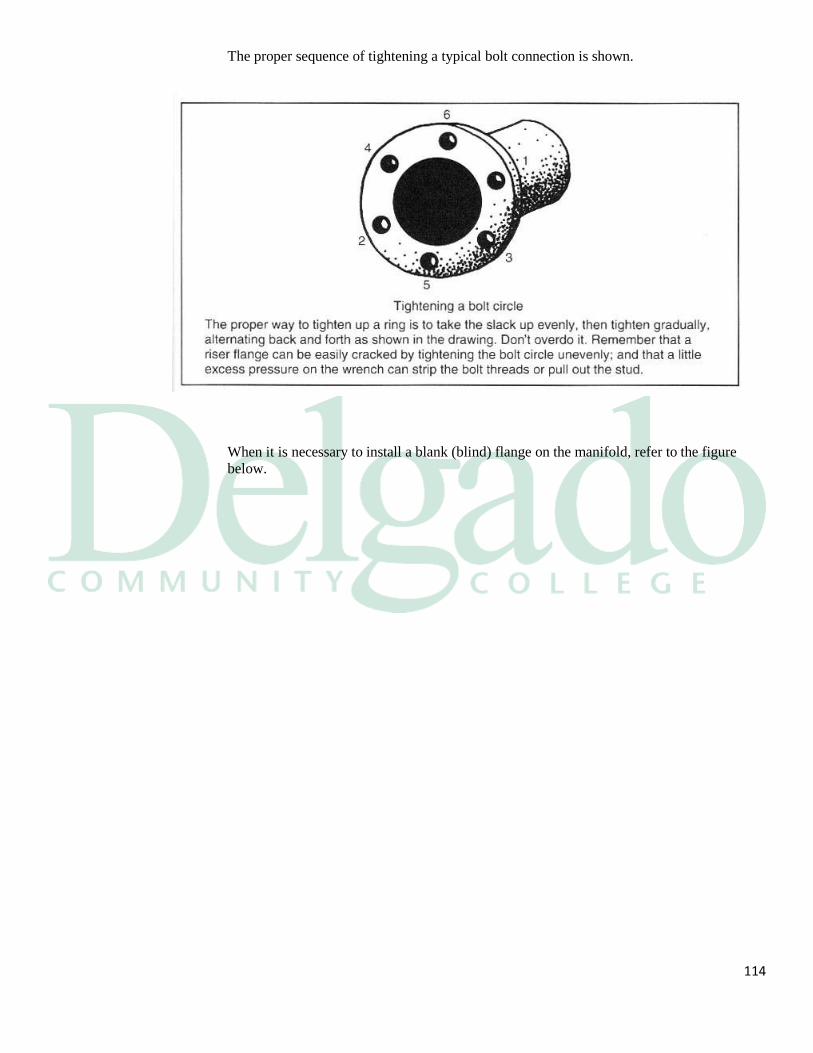
114
The proper sequence of tightening a typical bolt connection is shown.
When it is necessary to install a blank (blind) flange on the manifold, refer to the figure
below.
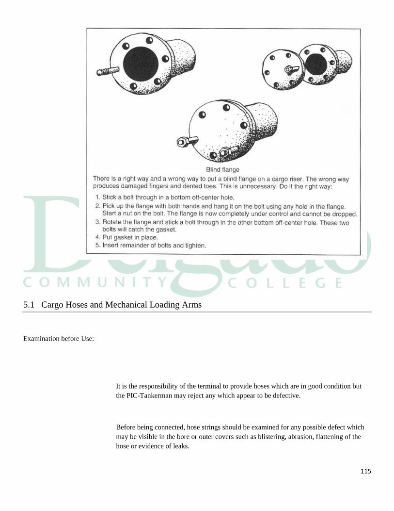
115
5.1 Cargo Hoses and Mechanical Loading Arms
Examination before Use:
It is the responsibility of the terminal to provide hoses which are in good condition but
the PIC-Tankerman may reject any which appear to be defective.
Before being connected, hose strings should be examined for any possible defect which
may be visible in the bore or outer covers such as blistering, abrasion, flattening of the
hose or evidence of leaks.
116
Hoses to be used should have been pressure tested to manufacturer's specifications at
intervals which are in accordance with the manufacturer's recommendations. Intervals
between tests should not in any case exceed one year. The date of such pressure testing
should be indicated on the hose. Hoses for which the rated pressure has been exceeded
must be removed and retested before further use.
Handling, Lifting and Suspending:
Hoses should always be handled with care and should not be dragged over a surface or
rolled in a manner which twists the body of the hose. Hoses should not be allowed to
come into contact with a hot surface such as a steam pipe. Protection should be provided
at any point where chafing or rubbing can occur.
Lifting bridles and saddles should be provided. The use of steel wires in direct contact
with the hose cover should not be permitted. Hoses should not be lifted at a single point
with ends hanging down but should be supported at a number of places so that they are
not bent to a radius less than that recommended by the manufacturer.
Excessive weight on the vessel's manifold should be avoided. If there is an excessive
overhang, or the vessel's valve is outside the stool support, additional support should be
given to the manifold. A horizontal curved plate or pipe section should be fitted at the
vessel's side to protect the hose from sharp edges and obstructions.
Adequate support for the hose when connected to the manifold should be provided.
Where this is a single lifting point, such as a derrick, the hose string should be supported
by bridles or saddles.
Adjustment During Cargo Handling Operations:
As the vessel rises or falls a result of tide or cargo operations, the hose strings should
be adjusted so as to avoid undue strain on the hoses, connections and ship's manifold and
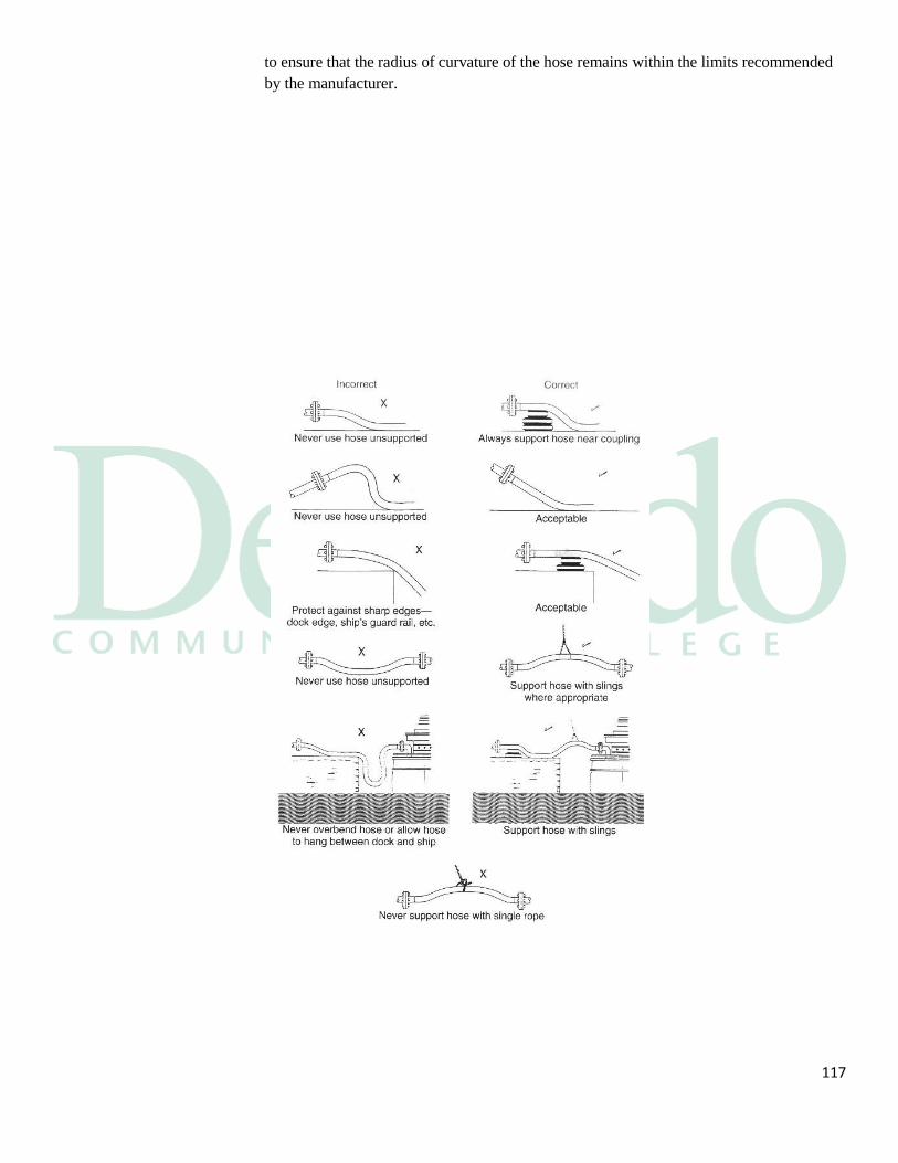
117
to ensure that the radius of curvature of the hose remains within the limits recommended
by the manufacturer.

118
Mechanical Loading Arms:
Shore facilities that accommodate large vessels and have high cargo transfer rates
frequently use mechanical loading arms, which are steel pipes that telescope to make the
connection with the vessel manifold. These are often referred to as “chicksans.”
Mechanical arms are controlled hydraulically and employ swivel joints which enable
them to follow the movement of the vessel at the berth. Although steel arms are capable
of handling greater pressures and flow rates than hoses, the person-in-charge should be
aware of several concerns with their use.
Mechanical arms have limited operating envelope, which means they are much less
forgiving than cargo hoses when the vessel begins to surge or drift at the dock. The
facility PIC should take this into account when spotting the vessel and properly tend the
moorings to ensure the vessel stays in position at the berth.

119
Most mechanical loading arms employ some form of quick-connect coupling
such as hydraulic clamps or Cam-Locks when connecting to the manifold. As in
the case of cargo hoses, it is imperative that suitable gasket material or O-rings
be installed in the connection to maintain a leak-free seal.
In the United States mechanical loading arms must meet the design, fabrication,
material, as well as inspection and testing requirements.
At the end of a cargo transfer there must be a means to drain or close off the arm
prior to breaking the connection.
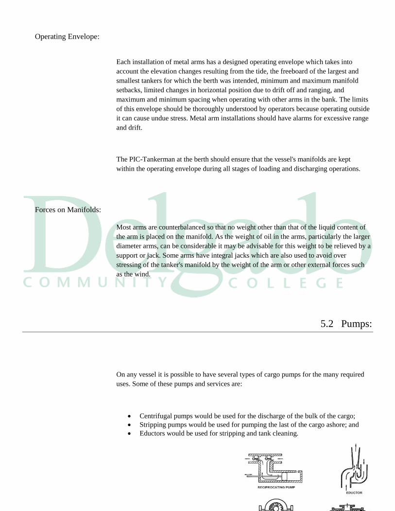
120
Operating Envelope:
Each installation of metal arms has a designed operating envelope which takes into
account the elevation changes resulting from the tide, the freeboard of the largest and
smallest tankers for which the berth was intended, minimum and maximum manifold
setbacks, limited changes in horizontal position due to drift off and ranging, and
maximum and minimum spacing when operating with other arms in the bank. The limits
of this envelope should be thoroughly understood by operators because operating outside
it can cause undue stress. Metal arm installations should have alarms for excessive range
and drift.
The PIC-Tankerman at the berth should ensure that the vessel's manifolds are kept
within the operating envelope during all stages of loading and discharging operations.
Forces on Manifolds:
Most arms are counterbalanced so that no weight other than that of the liquid content of
the arm is placed on the manifold. As the weight of oil in the arms, particularly the larger
diameter arms, can be considerable it may be advisable for this weight to be relieved by a
support or jack. Some arms have integral jacks which are also used to avoid over
stressing of the tanker's manifold by the weight of the arm or other external forces such
as the wind.
5.2 Pumps:
On any vessel it is possible to have several types of cargo pumps for the many required
uses. Some of these pumps and services are:
Centrifugal pumps would be used for the discharge of the bulk of the cargo;
Stripping pumps would be used for pumping the last of the cargo ashore; and
Eductors would be used for stripping and tank cleaning.
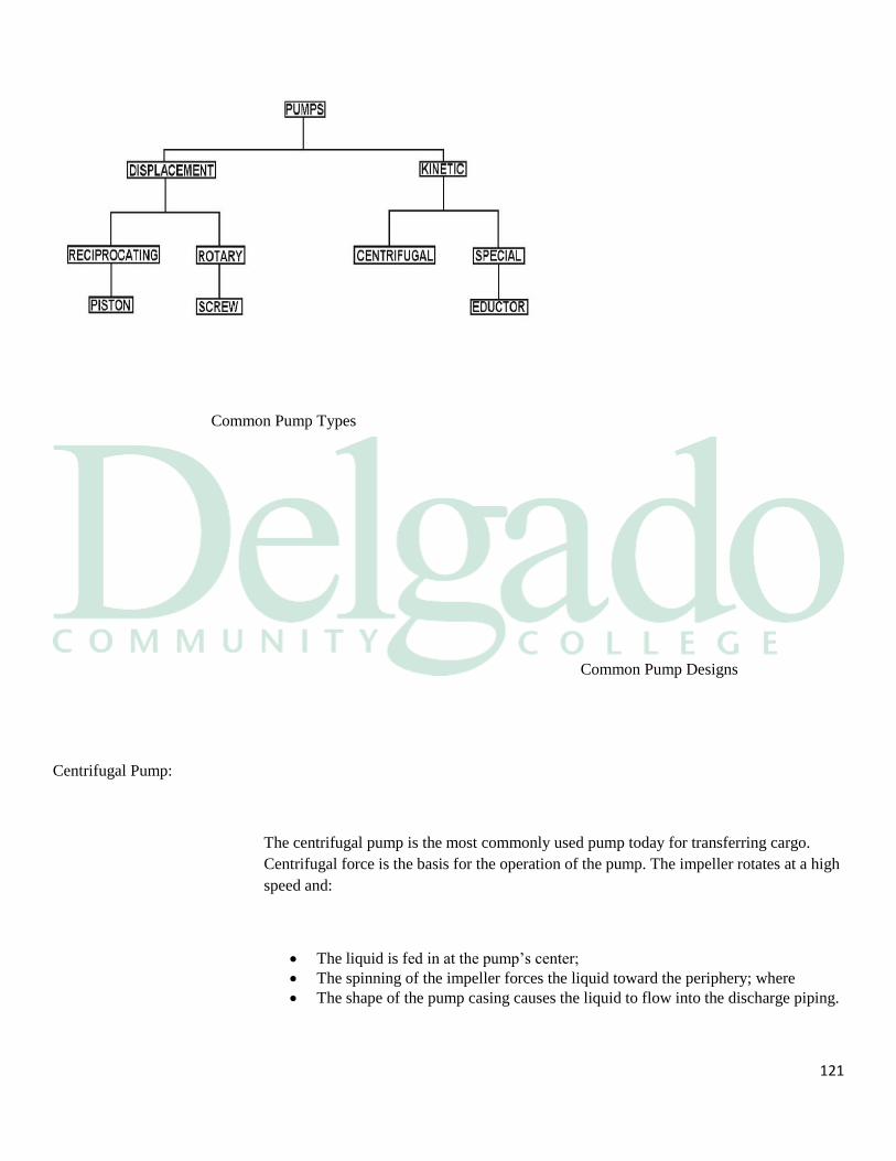
121
Common Pump Types
Common Pump Designs
Centrifugal Pump:
The centrifugal pump is the most commonly used pump today for transferring cargo.
Centrifugal force is the basis for the operation of the pump. The impeller rotates at a high
speed and:
The liquid is fed in at the pump’s center;
The spinning of the impeller forces the liquid toward the periphery; where
The shape of the pump casing causes the liquid to flow into the discharge piping.

122
Centrifugal pumps are most efficient when pumping large volumes at low to moderate
pressures. Deepwell pumps are centrifugal, hydraulically or electrically driven
submerged cargo pumps. The bottom of the pump is usually submerged in a sump in the
after bottom of a tank. The pumps are totally enclosed with the impeller at the bottom of
the pump and they are usually placed in each cargo tank, eliminating the need for bottom
piping and the pumproom. Ships fitted with deepwell pumps have no bottom lines. Each
tank has an encased deepwell cargo pump located at the after inboard section of each
tank. Each pump has its own discharge pipe running to the manifold. When the pump is
running it will pump cargo up the pump casing to the manifold via the discharge pipe.
Centrifugal pumps may be classified in several ways. For example, they may be either
single-stage or multi-stage. A single-stage pump has only one impeller; a multistage
pump has two or more impellers housed together in one casing. In a multistage pump,
each impeller usually acts separately, discharging to the suction of the next stage
impeller. Centrifugal pumps are also classified as horizontal or vertical, depending on the
position of the pump shaft. Impellers used in centrifugal pumps may be classified as
single-suction or double-suction, depending on the way in which liquid enters the eye of
the impeller.
Positive Displacement Pump:
123
A positive displacement pump will discharge the volume of liquid it suctioned through it
during each cycle of operation. If the liquid flow is blocked, the pressure will rise rapidly
in the positive displacement pump. Examples of these pumps are:
Reciprocating pumps
Screw pumps
Lobe pumps
Positive displacement pumps are generally used as stripping pumps because they are
most efficient at pumping small volumes at high pressures.
Eductors make use of a physical phenomenon known as the venturi effect. A driving fluid
is pumped through a nozzle that creates:
A radical increase in the fluid’s velocity
A vacuum near the nozzle
A suction at the nozzle
Eductors are self-priming and efficient in stripping systems, but the driving fluid and the
fluid being pumped must be compatible because they will become common and discharge
into the same tank.
5.3 Pump Theory
Pump Theory:
Strictly speaking, a pump does not draw up a liquid, but rather creates a vacuum on the
suction side, allowing atmospheric pressure to push the liquid into the pump. In theory, a
pump could therefore draw up a liquid column corresponding to the atmospheric
pressure, which equals about 10 meters of water (for which the relative density is 1)
In practice, the situation is different. Theoretically suction height is influenced in a
positive way by atmospheric pressure, inert gas pressure and the height of liquid in the
tank; it is negatively influenced by the net positive suction head (NPSH) of the pumps,
frictional losses in the pipelines, true vapor pressure of the liquid being pumped, and the
height of pump and suction piping above the tank bottom. All these can be expressed in
meters liquid column.
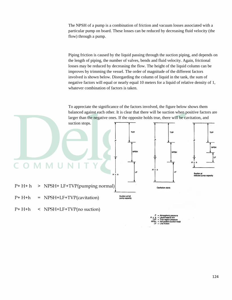
124
The NPSH of a pump is a combination of friction and vacuum losses associated with a
particular pump on board. These losses can be reduced by decreasing fluid velocity (the
flow) through a pump.
Piping friction is caused by the liquid passing through the suction piping, and depends on
the length of piping, the number of valves, bends and fluid velocity. Again, frictional
losses may be reduced by decreasing the flow. The height of the liquid column can be
improves by trimming the vessel. The order of magnitude of the different factors
involved is shown below. Disregarding the column of liquid in the tank, the sum of
negative factors will equal or nearly equal 10 meters for a liquid of relative density of 1,
whatever combination of factors is taken.
To appreciate the significance of the factors involved, the figure below shows them
balanced against each other. It is clear that there will be suction when positive factors are
larger than the negative ones. If the opposite holds true, there will be cavitation, and
suction stops.
P+ H+ h > NPSH+ LF+TVP(pumping normal)
P+ H+h = NPSH+LF+TVP(cavitation)
P+ H+h < NPSH+LF+TVP(no suction)
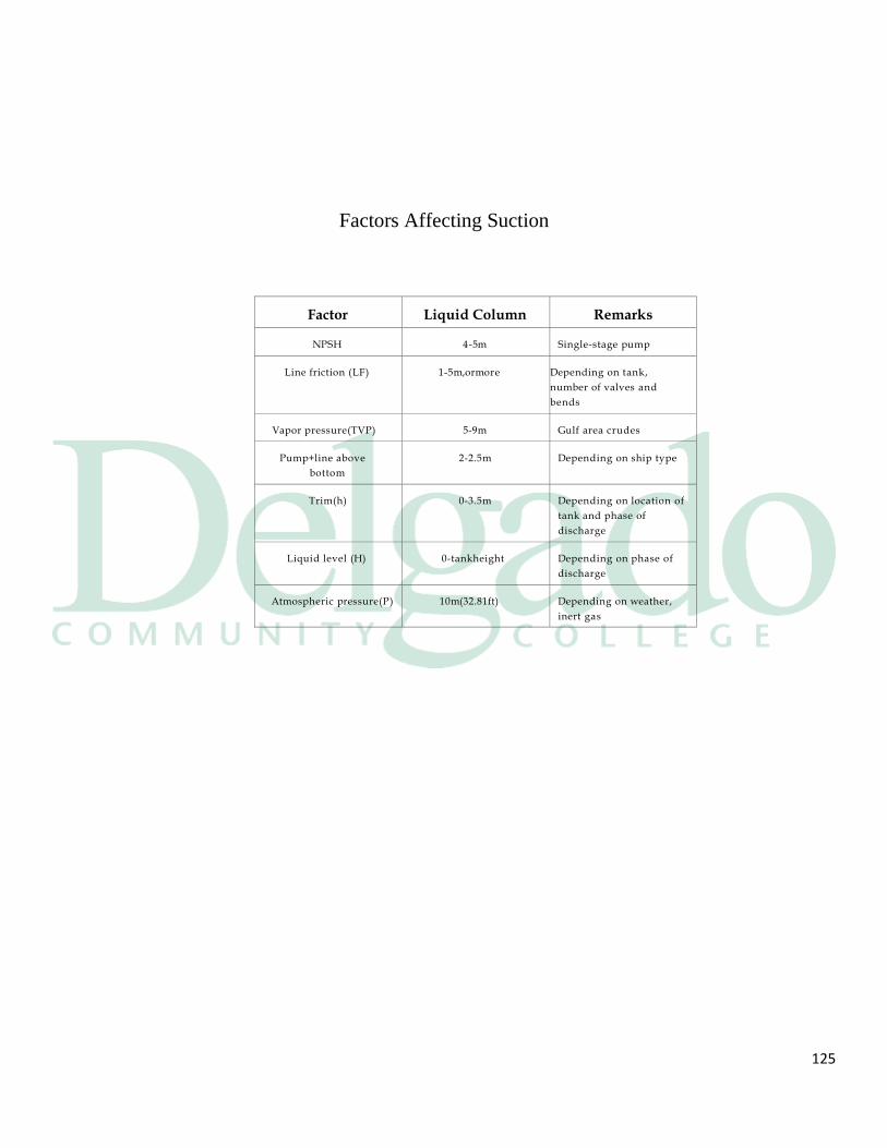
125
Factor Liquid Column Remarks
NPSH
4-5m
Single-stage pump
Line friction (LF)
1-5m,ormore
Depending on tank,
number of valves and
bends
Vapor pressure(TVP)
5-9m
Gulf area crudes
Pump+line above
bottom
2-2.5m
Depending on ship type
Trim(h)
0-3.5m
Depending on location of
tank and phase of
discharge
Liquid level (H)
0-tankheight
Depending on phase of
discharge
Atmospheric pressure(P)
10m(32.81ft)
Depending on weather,
inert gas
Factors Affecting Suction
126
As the maximum available suction head is approached, bubble pressure is reached and
vapor forms thorough out the liquid, i.e. the liquid boils. During a short period of time a
liquid/vapor mixture of varying relative density is created. The resulting fluctuations in
pressure (caused by the liquid column being drawn in) and in pump power can be
observed as fluctuations in discharge pressure and in revolutions of the pump.
Cavitation occurs and the rattle of imploding bubbles can be heard distinctly. Since a
mixture of liquid and vapor is being pumped, the liquid velocity in the suction piping
decreases, line resistance decreases and suction is maintained for a short while. Soon only
vapor will be drawn in and the flow will stop, even though a considerable quantity of oil
may remain in the tank.
If the pump is to be kept working, both NPSH and line resistance may be influenced by
reducing the discharge rate. The lower liquid velocity reduces both line resistance and
NPSH, ensuring that the bubble- point pressure is not reached.
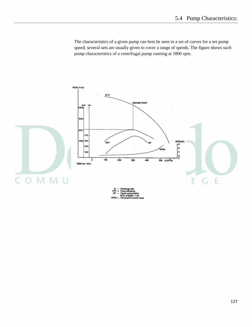
127
5.4 Pump Characteristics:
The characteristics of a given pump can best be seen in a set of curves for a set pump
speed; several sets are usually given to cover a range of speeds. The figure shows such
pump characteristics of a centrifugal pump running at 1800 rpm.
128
The vertical axis shows the scales for the various curves, while the horizontal axis shows
the discharge rate as a function of head, expressed in meters of liquid column. To every
pump speed there is a Q-H curve which gives the relationship between head and
discharge rate. If the head is known, it is possible to determine the discharge rate. Head, it
should be noted, is not equal to backpressure. To convert backpressure into head, the
difference between backpressure and suction pressure should be converted into meters
water gauge and divided by the relative density of the liquid being pumped. The design
point marked on the curve represents the most economical working condition of the
pump. This is also reflected in the efficiency curve (EFF). Other curves to be seen are
NPSH and power consumption of the pump in horsepower (HP)
At 1800 rpm, the pump is operating somewhere along curve Q-H curve. The actual point
depends on where the Q-H curve crosses the shore curve, which represents the pressure a
pump has to work against. The pressure is partially static, depending on the difference in
height between liquid levels ashore and on board, and partially dynamic, owing to line
resistance.
Pumps running in parallel have a common Q-H curve which can be constructed by
adding the curves horizontally. It is interesting to note that if the shore curve is steep, i.e.
if backpressure is high, the difference in output between one pump and more than one
pump is not great, in contrast to the situation where the shore curve is more gradually
inclined, representing low backpressure.
5.5 Pressure Surge:
A pressure surge is generated in a pipeline system when there is an abrupt change in the
rate of flow of liquid in the line. In tanker operations it is most likely to occur as a result
of one of the following during loading:
Closure of an automatic shutdown valve.
Slamming shut of a shore non-return valve.
129
Slamming shut of a butterfly type valve.
Rapid closure of a power operated valve.
If the pressure surge in the pipeline results in pressure stresses or displacement stresses in
excess of the strength of the piping or its components, there may be a rupture leading to
an extensive spill of oil.
Generation of Pressure Surge:
When a pump is used to convey liquid from a feed tank down a pipeline and through a
valve into a receiving tank, the pressure at any point in the system while the liquid is
flowing has three components:
Pressure on the surface of the liquid in the feed tank. In a tank with its ullage
space communicating to atmosphere this pressure is that of the atmosphere.
Hydrostatic pressure at the point in the system in question.
Pressure generated by the pump. This is highest at the pump outlet, decreasing
commensurately with friction along the line downstream of the pump and through
the valve to the receiving tank.
Of these three components, the first two can be considered constant during pressure surge
and need not be considered in the following description, although they are always present
and have a contributory effect on the total pressure.
Rapid closure of the valve superimposes a transient pressure upon all three components,
owing to the sudden conversion of the kinetic energy of the moving liquid into strain
energy by compression of the fluid and expansion of the pipe wall. To illustrate the
sequence of events the simplest hypothetical case will be considered, i.e. when the valve
closure is instantaneous, there is no expansion of the pipe wall, and dissipation due to
friction between the fluid and the pipe wall is ignored. This case gives rise to the highest
pressures in the system.
When the valve closes, the liquid immediately upstream of the valve is brought to rest
instantaneously. This causes its pressure to rise by an amount P in any consistent set of
units:
130
P = WAV
Where: W is the mass density of the liquid.
A is the velocity of sound in the liquid.
V is the change in linear velocity of the liquid i.e. from its linear flow rate before
closure.
The cessation of flow of liquid is propagated back up the pipeline at the speed of sound in
the fluid, and as each part of the liquid comes to rest its pressure is increased by the
amount P. Therefore a steep pressure front of height P travels up the pipeline at the speed
of sound; this disturbance is known as a pressure surge.
Upstream of the surge, the liquid is still moving forward and still has the pressure
distribution applied to it by the pump. Behind it the liquid is stationary and its pressure
has been increased at all points by the constant amount P. There is still a pressure
gradient downstream of the surge but a continuous series of pressure adjustments takes
place in this part of the pipeline which ultimately result in a uniform pressure throughout
the stationary liquid. These pressure adjustments also travel through the liquid — at the
speed of sound.
When the surge reaches the pump the pressure at the pump outlet (ignoring the
atmospheric and hydrostatic components) becomes the sum of the surge pressure P and
the output pressure of the pump at zero throughput (assuming no reversal of flow), since
flow through the pump has ceased. The process of pressure equalization continues
downstream of the pump. Again taking the hypothetical worst case, if the pressure is not
relieved in any way, the final result is a pressure wave that oscillates throughout the
length of the piping system.
In this simplified description, therefore, the liquid at any point in the line experiences an
abrupt increase in pressure by an amount P followed by a slower, but still rapid, further
increase until the pressure reaches the sum of P and the pump outlet pressure at zero
throughput.
131
In practical circumstances the valve closure is not instantaneous and there is thus some
relief of the surge pressure through the valve while it is closing.
At the upstream end of the line some pressure relief may occur through the pump and this
would also serve to lessen the maximum pressure reached. If the effective closure time of
the valve is several times greater than the pipeline period, pressure relief through the
valve and the pump is extensive and a hazardous situation is unlikely to arise.
Downstream of the valve an analogous process is initiated when the valve closes, except
that as the liquid is brought to rest there is a fall of pressure which travels downstream at
the velocity of sound. However, the pressure drop is often relieved by gas evolution from
the liquid so that serious results may not occur immediately, although the subsequent
collapse of the gas bubbles may generate shock waves similar to those upstream of the
valve.
5.6 Cargo Pump Definitions
132
Design Point: The design point is the point on the pump performance curve that corresponds to the Best
Efficiency Point.
Head: The head is the vertical distance between the level of the pump and the top level of the
liquid in the tank being discharged.
Suction Head: Suction head is the term expressing positive pressure at the pump suction.
NPSH: Net positive suction head is the positive head of fluid required at the pump suction over
and above the liquid vapor pressure to prevent capitation at the pump impeller.
Velocity Head: The velocity head is equivalent backpressure due to the movement of a fluid. It is
calculated by dividing the velocity in ft. /sec by twice the acceleration of gravity.
Discharge Head: The discharge head is the amount of pressure due to the sum of discharge factors:
The vertical height of discharge
The velocity head
Any friction losses
Suction Lift: The suction lift is the sum of losses at the suction that must be overcome by the pump. It
consists of the sum of:
Vertical lift
Friction losses
Entrance losses
Total Head: Total head is the sum of suction lift and discharge head.
Static Head: Static backpressure or static head is the difference in the liquid levels of the tank being
pumped from and the tank being pumped into.
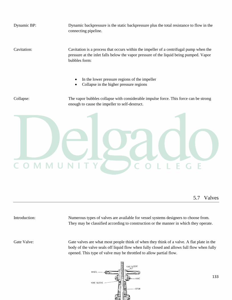
133
Dynamic BP: Dynamic backpressure is the static backpressure plus the total resistance to flow in the
connecting pipeline.
Cavitation: Cavitation is a process that occurs within the impeller of a centrifugal pump when the
pressure at the inlet falls below the vapor pressure of the liquid being pumped. Vapor
bubbles form:
In the lower pressure regions of the impeller
Collapse in the higher pressure regions
Collapse: The vapor bubbles collapse with considerable impulse force. This force can be strong
enough to cause the impeller to self-destruct.
5.7 Valves
Introduction: Numerous types of valves are available for vessel systems designers to choose from.
They may be classified according to construction or the manner in which they operate.
Gate Valve: Gate valves are what most people think of when they think of a valve. A flat plate in the
body of the valve seals off liquid flow when fully closed and allows full flow when fully
opened. This type of valve may be throttled to allow partial flow.

134
Globe Valve: Globe valves have a circular seat upon which a globe sits to close the valve. Since this
design requires a 90° change of direction for the flowing liquid, friction within the valve
is higher than in a gate valve.
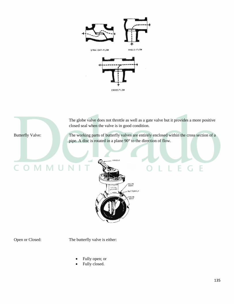
135
The globe valve does not throttle as well as a gate valve but it provides a more positive
closed seal when the valve is in good condition.
Butterfly Valve: The working parts of butterfly valves are entirely enclosed within the cross section of a
pipe. A disc is rotated in a plane 90° to the direction of flow.
Open or Closed: The butterfly valve is either:
Fully open; or
Fully closed.
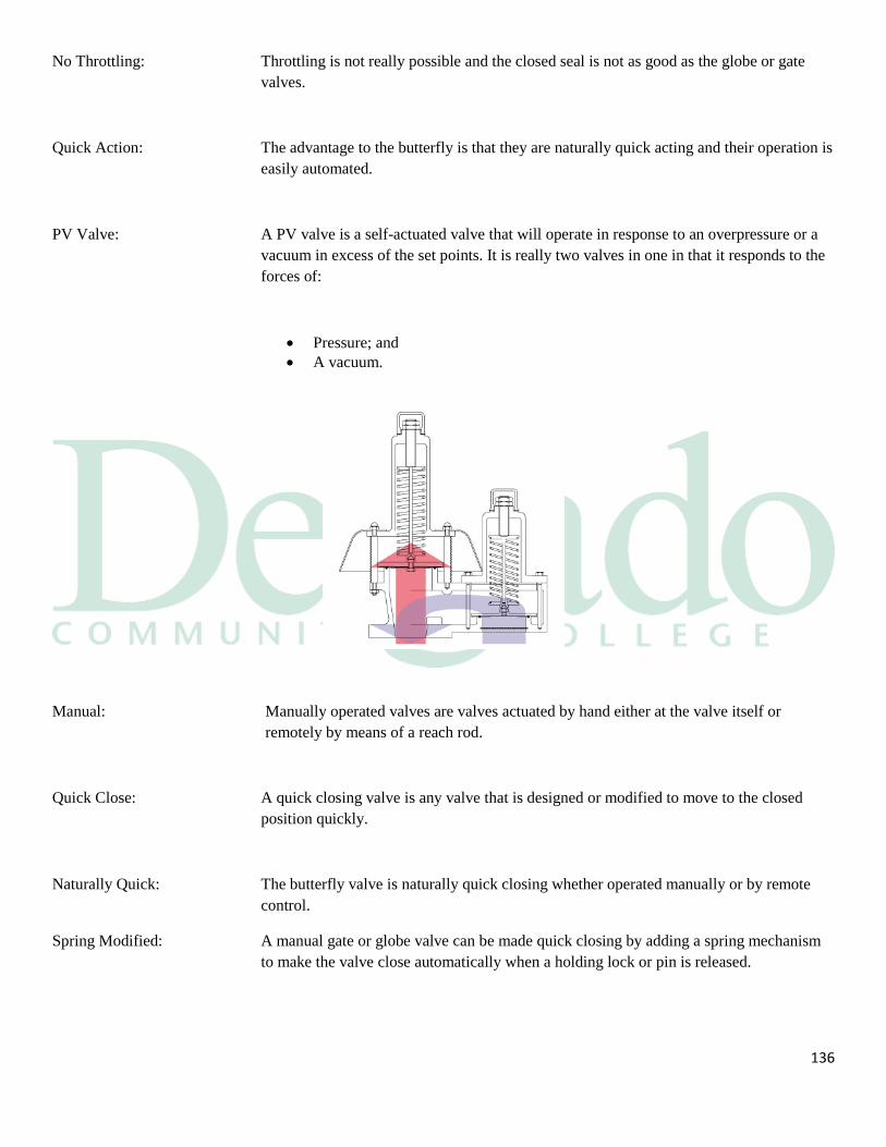
136
No Throttling: Throttling is not really possible and the closed seal is not as good as the globe or gate
valves.
Quick Action: The advantage to the butterfly is that they are naturally quick acting and their operation is
easily automated.
PV Valve: A PV valve is a self-actuated valve that will operate in response to an overpressure or a
vacuum in excess of the set points. It is really two valves in one in that it responds to the
forces of:
Pressure; and
A vacuum.
Manual: Manually operated valves are valves actuated by hand either at the valve itself or
remotely by means of a reach rod.
Quick Close: A quick closing valve is any valve that is designed or modified to move to the closed
position quickly.
Naturally Quick: The butterfly valve is naturally quick closing whether operated manually or by remote
control.
Spring Modified: A manual gate or globe valve can be made quick closing by adding a spring mechanism
to make the valve close automatically when a holding lock or pin is released.
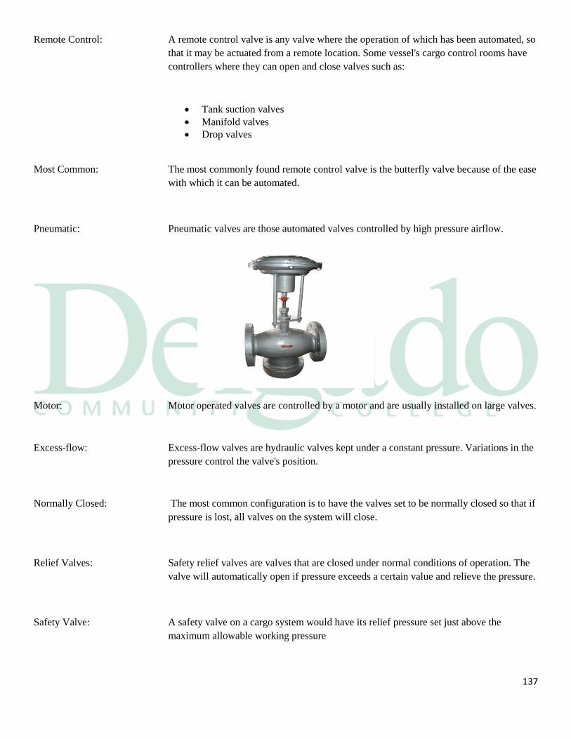
137
Remote Control: A remote control valve is any valve where the operation of which has been automated, so
that it may be actuated from a remote location. Some vessel's cargo control rooms have
controllers where they can open and close valves such as:
Tank suction valves
Manifold valves
Drop valves
Most Common: The most commonly found remote control valve is the butterfly valve because of the ease
with which it can be automated.
Pneumatic: Pneumatic valves are those automated valves controlled by high pressure airflow.
Motor: Motor operated valves are controlled by a motor and are usually installed on large valves.
Excess-flow: Excess-flow valves are hydraulic valves kept under a constant pressure. Variations in the
pressure control the valve's position.
Normally Closed: The most common configuration is to have the valves set to be normally closed so that if
pressure is lost, all valves on the system will close.
Relief Valves: Safety relief valves are valves that are closed under normal conditions of operation. The
valve will automatically open if pressure exceeds a certain value and relieve the pressure.
Safety Valve: A safety valve on a cargo system would have its relief pressure set just above the
maximum allowable working pressure
138
•
5.8 Instrumentation
Introduction: Modern technology has given systems designers the capability to remotely measure any
number of physical states and quantities. The most common remotely measured items on
barges are:
Cargo tank levels
Cargo temperatures
Tank atmospheres
Pipeline pressures
Pump performances
Drafts
Read-outs: The measured quantities can be used to automatically calculate others. The cargo tank
level readout can be calibrated to read out as a tank volume in barrels or meters.
Telemetry: The transmission of the measured data from the remote location to the readout is known
as telemetry. Components of telemetry systems are the:
Transducer
Measuring transmitter
Controller
Pneumatics
139
Transducer Transmitter: The transducer is a device which converts information from one physical form at its input
to another at its output.
Types: A measuring transmitter is a device that converts the measured quantity into a signal that
is easily transmitted long distances with little signal loss.
Both pneumatic and electrical transmitters are used on vessels.
Controller: The controller is a device that compares the signal from the transmitter to:
A signal representing the set-point
Automatically operates the controlling mechanism to adjust the manipulated
device
Span: The span is the range of values over which a meter is set to indicate, or a device is set to
operate.
Adjustment: A span adjustment is part of the calibration process.
Zero: Zero is the minimum value of the measurement or control range.
Pneumatic: Pneumatic means air operated.
Electronic to Air: This converter is typically used to convert a control signal for a valve into an air signal
used by the valve's positioner.
Value Converted: All values that are measured remotely are converted into a signal, either:
Pneumatic; or
Electrical
Control Signal: The signal for any of the measured values can also be used as a control signal for other
equipment. The signal corresponding to a certain level in the tank can be tapped to:
140
Ring an alarm
Shut down pumps
And close valves
Activate Alarm: In the first case the measurement signal has been used to activate a high level alarm and
in the second case for an emergency shutdown.
Shut Down: Any of the measured values can be used to provide a signal that will shut off a system or
any part of it.
141
Section 6
Loading and Discharging Operations
Introduction: In this section we will look at loading the vessel and take you from receiving the cargo
orders through finishing the load and preparing the vessel to get underway. Some of these
steps we will go through are:
Planning the load
Preparing the vessel for dock arrival
Preparing for loading at the berth
Loading
Transferring cargo custody
Securing from the loading operations;
Preparing to get underway
142
Voyage Orders: The first step in planning the load is a careful examination of the cargo or voyage orders.
The information should be explicit and you should have no questions. Your voyage
orders should contain the following:
Loading terminal and port
Volume to load
Product grade
API
Cargo temperature
Special terminal requirements
Heating requirements
Any product special properties
Discharge terminal and port
Volume to discharge
Sources: If any of this information is missing you will have to find it from other sources such as:
Your files from past voyages
Who issued the cargo orders?
The loading terminal
Develop a Plan: Developing the loading plan is one of the PIC Tankermen most challenging tasks.
Information must be gathered from a variety of sources and placed in a comprehensible
form from which the final loading plan is developed. You must determine if the vessel
can:
Cargo specifications and preferred order of loading
Whether or not the cargo includes toxic components, for example H2S Benzene,
etc.
Tank venting requirements
Any other characteristics of the cargo requiring attention, for example high true
vapor pressure
Flashpoints (where applicable) of products and their estimated loading
temperatures, particularly when the cargo is non-volatile
Nominated quantities of cargo to be loaded
Maximum shore loading rates
Standby time for normal pump stopping
Maximum pressure available at the berth cargo connection
Deal with cargo expansion during the voyage
Load the cargoes simultaneously
Discharge the cargo in the ordered sequence
143
Revise Plan: If one or more of the above is negative, you will have to work out a different load from
the orders as close to the ordered volumes as you can. After doing this you will have to:
Present the reasons the orders cannot be complied with
Wait for new cargo orders from the charterer
Work on the new plan when the orders come in
Accept Orders: Once it has been determined that the vessel can carry the revised cargo deadweight and
volume, then the:
PIC Tankerman will formally accept the orders
The plan will start to fall into place
The final layout of the cargo can begin
Load Planning: The proposed cargo layout is now finished and the final planning can continue. To
finalize the load plan you must:
Calculate the stop ullages
Determine the manifolds you will use
Determine the loading sequence
Assign the maximum loading rate
Assign the spill tanks
Load Plan: The load plan should also contain the following:
The total quantity of each grade
The final ullage for each tank
The segregations for each grade (if any)
The pipelines to be used for each grade
Precautions to be taken to prevent cross-contamination
The maximum and desired loading rates
Operating pressure
Any final tank preparations to be taken prior to loading
Vessel or shore stop information
Custodial Duties: Custodial duties should be written into the plan such as:
144
The amount of samples to take
Information on gauges and gauging
The vessel's record keeping requirements
6.1 Pre-Arrival Preparations for Dock
Preparations: This section discusses the physical preparations that are carried out prior to arrival at the
load port. The actions may include such items as:
Details of last cargo carried, method of tank cleaning (if any) and state of the
cargo tanks and lines
Where the vessel has part cargoes on board, grade, volume and tank distribution
Maximum acceptable loading rates and topping off rates
Maximum acceptable pressure at the barge/shore cargo connection during
loading
Cargo quantities acceptable from terminal nominations
Proposed disposition of nominated cargo and preferred order of loading
Maximum acceptable cargo temperature (where applicable)
Maximum acceptable true vapor pressure (where applicable)
Proposed method of venting
Quantity, quality and disposition of slops
Quality of inert gas (if applicable)
Lineup of the cargo systems
Preparing the manifold
Check the vapor emissions control
Line up the firefighting equipment
Check the containment systems are in compliance
Ensure that pollution prevention requirements are met
Inspection of Cargo Tanks Before Loading:
145
Where possible, inspection of vessel's tanks before loading cargo should be made without
entering the tanks.
A tank inspection can be made from the deck using ullage or sighting ports with, where
applicable, the inert gas within the tank maintained at its minimum positive pressure.
Care must be taken by the person inspecting not to inhale vapors or inert gas when
inspecting tanks which have not been gas freed.
Frequently tank atmospheres which are, or have been, inerted have a blue haze which,
together with the size of the tanks, makes it difficult to see the bottom even with the aid
of a powerful torch or strong sunlight reflected by a mirror. It may sometimes be
necessary to remove tank cleaning opening covers to sight parts of the tank not visible
from the ullage ports but this should only be done when the tank is gas free, and the
covers must be replaced and secured immediately after the inspection.
If, because the cargo to be loaded has a critical specification, it is necessary for the
inspector to enter a tank, all the precautions must be followed. Before entering a tank
which has been inerted, it must be gas freed for entry and, unless all tanks are gas freed
and the IGS completely isolated, each individual tank to be entered for inspection must
be isolated from the IGS.
Inert Arrivals: If the vessel is to arrive with the tanks stripped and in the inserted condition you must do
thing a little differently. You should insure the tanks are:
Stripped dry
Purged of the hydrocarbon content down to 40% or less of the LFL with IG
At an 02 content of 8% or lower
There is positive IG pressure in the tanks

146
Final Checks: To save time and confusion at the dock you should do your final checklist prior to
berthing. Some of these final checks are:
Mooring lines are pulled and ready
Reducers and spool pieces are in place
Manifold’s mix-PIC Tankerman is lined up correctly
Main deck crossovers and blocks are lined up correctly
Valves are positioned correctly
Vapor control system is lined up correctly
Check the high level alarms
Firefighting equipment is lined up
Containment system is properly set up
Oil spill gear is in place

147
6.2 Loading the Vessel
Gaugers Aboard: Once the vessel is securely moored the tank inspectors will board the vessel. They will
inspect the tanks for cleanliness; and suitability to receive the intended cargo.
Connect Hoses: The hoses must be connected to the proper manifolds. The Person-In-Charge should be
present while the hoses and ground wire are connected and must verify that they have
been properly connected as per 33 CFR 156.160.
Conference: The Pre-transfer Conference is the regulatory requirement 33 CFR 156.120 and it states
the items that must be covered during this conference between the Persons-In-Charge of
the transferring and receiving units shall:
148
Identify the product(s) to be transferred
Name the sequence of transfer operations
Agree on the transfer rate
Identify the persons or title and location of each person participating in the
transfer operation
Give details of the transferring and receiving systems
State the critical stages of the transfer operation
Acknowledge the federal, state and local rules that apply to the transfer
Display the emergency procedures
Confirm the spill containment procedures
Confirm spill reporting procedures
Confirm the watch or shift arrangements
Agree that the Persons-In-Charge may begin the transfer operation
The Declaration: You must fill out the DOI or the equivalent Vessel/Shore Safety Checklist recommended
prior to loading. Both PersonsIn-Charge are required to:
Check off all items on this checklist
Sign off on this checklist
All reliefs must also sign at each watch change
Check off each item on the checklist
The purpose of the Check List is to ensure the safety of both vessel and terminal and of
all personnel and it should be completed jointly by a responsible officer and the terminal
representative. Each item should be verified before it is ticked. This will entail a physical
check by the two persons concerned and will be conducted jointly where appropriate. It is
of no value if it is merely regarded as a paper exercise.
149
Communications: To ensure the safe control of operations at all times, it should be the responsibility of both
parties to establish, agree in writing and maintain a reliable communications system.
Before loading or discharging commences, the system should be adequately tested. A
secondary stand-by system should also be established and agreed. Allowance should be
made for the time required for action in response to signals. These systems should
include signals for:
Identification of vessel, berth and cargo
Stand by
Start loading or start discharging
Slow down
Stop loading or stop discharging
Emergency stop
Start of Cargo: When you are ready to start the load you should start with one product into one tank.
Open that tank valve and then:
Open all valves between tank and manifold
Open the manifold valve last
Inform the shore that you are ready to begin
Start cargo flow slowly into one tank
Get a header sample for the product
Verify that cargo is only flowing to that tank
Cushioning: Filling slowly to cover the bell mouth is called bottom cushioning. Coast Guard
guidelines advises a slow flow starting rate for most petroleum based products to test the
system prior to bringing it up to the agreed upon rate. When putting the cushion in you
should:
Check the opposite manifold for leaks
Check the hose connections for leaks
Check the pipelines for leaks
Check the pump room for leaks
Get your bottom samples
Increase Rate: Once satisfied, slowly increase the cargo flow until the full loading rate is achieved.
150
Loading Cargo: The start-up procedures, mentioned above, will be repeated for each grade to be loaded.
Once all grades to be loaded simultaneously have been started, the bulk of the load
continues until the topping off phase is reached. During loading, the Person-In-Charge is
responsible for:
Tending to the moorings and gangway frequently
Making frequent rounds of the deck and checking for leaks
Checking the nearby water frequently looking for oil on the water
Making rounds throughout the house and other spaces as an hourly fire watch
Enforcing the visitor policy
Monitoring pressure at the manifold
Performing ballast/DE ballast operations as required
Monitoring ullages
Performing any checks as the situation dictates
Spill Tank: At least one tank for each grade should have been shut off at about halfway full while
you loaded into the others. This tank is called the spill tank. The space in this tank is
saved for emergency use to ensure you have an extra space for cargo in case:
A valve fails to close on a tank you are topping
The shore fails to shut down when ordered
Other unforeseen emergencies Overfill devices.
As per 46 CFR 155.480
(b) Each tank vessel with a cargo capacity of 1,000 or more cubic meters (approximately
6,290 barrels), loading oil or oil residue as cargo, must have one overfill device that is
permanently installed on each cargo tank and meets the requirements of this section.
(2) On a tank barge, each cargo tank must be equipped with an overfill device that—
(i) Meets the requirements of 46 CFR 39.20-7(b)(2) and (b)(3) and (d)(1) through
(d)(4), and 46 CFR 39.20-9(a)(1) through (a)(3);
(ii) Is an installed automatic shutdown system that meets the requirements of 46 CFR
39.20-9(b); or
(iii) Is an installed high level indicating device that meets the requirements of 46
151
CFR 39.20-3(b)(1), (b)(2), and (b)(3).
(c) Each cargo tank of a U.S. flag tank vessel must have installed on it an overfill device
meeting the requirements of this section at the next scheduled cargo tank internal
examination performed on the vessel under 46 CFR 31.10-21.
Stick Gauge Overfill Devices:
A. 1-meter stick gauges are normally located forward of each ullage hatch. They provide
a visual indication of high level and overfill in the cargo tank. Follow these checks
before a transfer:
1. Uncap the stick gauges
2. Grasp the gauge firmly and pull it up carefully to the fully raised position.
3. Lower the stick until it engages the float magnet. This will be near at the bottom of
the stick's travel. The stick must engage the magnet in each tank in order to begin the
transfer.
4. When the cargo in each tank reaches approximately 1-meter ullage, the float and
gauge stick will begin to rise. It is important to make sure that the stick continues to
rise as the tank fills. This will help provide the best indication of the internal cargo
level.
5. The gauge sticks are normally marked with a green band which extends to the 6”
before overfill level, followed by a 6” yellow band extending to the overfill level.
The remainder of the stick is colored red. When loading cargo, the green color on the
stick indicates the normal loading of the tank, the yellow indicates near over fill (high
level) and the red means a dangerous over fill condition and the compartment cargo
valve should be closed immediately.
B. ALARM SYSTEM: Each cargo tank is equipped with cargo tank High Level/Overfill
Shutdown sensors. The High Level sensors will activate when the product level
reaches 96.5 percent of its capacity. This will occur when the product level in the
tank is approximately 10” below the deck. The Overflow Shutdown System will
activate at 98 percent capacity or 60 seconds before the tank becomes 100% full at
the maximum transfer rate. This will occur when the product level in the tank is
approximately 6” below the deck. These sensors must be connected to the appropriate
system before a visual or audio alarm will activate.

152
C. GAUGE TREE
1. Each cargo tank is equipped with a gauge tree located directly under each sight glass.
This tree will indicate the product level while the vessel is being loaded. The top rung
of the gauge tree is at deck level. The space between each descending tab is 6” with
the bottom rung being 6” above the deck level.
2. Each cargo tank is also equipped with a High Level and Overfill “Paddle” located so
as to be visible from each sight glass. The tree lower paddle indicates the product
level at the “High Level” setting of the alarm and the upper paddle indicates the
product level at the “Overfill” setting of the alarm.
Topping Off: This is the most critical time during bunkering operations, with respect to accidental oil
pollution. The vessel should advise the terminal when the final tanks are to be topped off
and request the terminal, in adequate time, to reduce the loading rate sufficiently to
permit effective control of the flow on board the vessel. After topping off individual
tanks, master valves should be shut, where possible, to provide two valve segregation of
loaded tanks. As the load progressed, the ullages should have been stepped to allow
you to top the tanks in the sequence you choose. As the oil level near their stops, you are
ready to commence topping off the tanks. You should:
Slow the loading rate down to your comfort zone
Call out the crew you planned on for topping off
Top off one or two tanks at a time
Shut the valves to the tanks you are not topping
Crack open the valves to the next tank for topping
Monitor the next tanks for their ullages
Monitor the topped tanks for creepage
As you close one valve down you are opening another
Keep in constant communication with your team and the terminal
Give the terminal sufficient notice for shut down
Finish the load into the spill tank
Displacements: At the pre-load conference you should have been told if the shore will require a line
displacement and received the volume they need to displace. You will have some
concerns during this operation, they are:
Is there enough space in the tank for the displacement; and
Will the displacement contaminate the tanks the product is entering?

153
Slowdown: You must make allowances for the shore to blow down their hoses in order to disconnect
them. They will either:
Blow the hoses to you; or
Drain the hoses back ashore.
Final Gauging: The gaugers will board the vessel and will first meet with the PIC Tankerman then they
will:
Gauge the ullages together
Read the temperatures together
One or the other will obtain the samples
Calculations: After the gauging is completed, the PIC Tankerman and the surveyors will independently
of each other, calculate each of the products:
Gross barrels
Net barrels
Long tons
Release: When these calculations are made and all is in agreement the surveyor or terminal
representative will release the vessel.
Documentation: There are many documents which become part of your voyage files and some of these are
as follows:
Notice to Readiness
Ullage and Deadweight report
Certificate of Quantity and Quality
Certificate of Origin
Bill of Lading
Cargo Manifest
Letter of Protest
Samples and Documents Receipt
Securing for Departure: After the vessel has been released and the hoses are away, the crew prepares the vessel
for getting underway:
154
Closing all cargo valves
Draining the manifold drip pans into the slop tank
Stowing the containment and cleanup gear
Ensuring all the paperwork is on board
Log Entries: Part of the custodial duties the watch officers incur are the log entries to be made. Some
of the standard entries are:
Arrival
First line
First hose connected
Commence load
Any stops of the load
Any resumes of the load
Completions of load
Last hose off
Last line
Departure
Underway: Cargo care and custodial duties during the loaded passage are usually accomplished by
daily inspections of the deck. Some of these items are:
Maintaining positive IG pressure (if required)
Maintaining temperature if required
Checking on expansion of cargo
Ensuring PN valves are freed up
Void Spaces: On the loaded passage, the void spaces should be checked daily for leakage by:
Soundings; or
By sight

155
156
6.3 Cargo Discharging Operations
Introduction: In this section we will look at discharging the vessel and take you from planning the
discharge through finishing the discharge and preparing the vessel to get underway. Some
of these steps we will go through are:
Planning the discharge
Preparing the vessel for berthing
Preparing for discharging at the berth
Discharging
Transferring cargo custody
Securing from the discharge operation
Preparing to get underway
Discharge Orders: The first step in planning the discharge is a careful examination of the discharge orders.
The information should be explicit and you should have no questions. Your discharge
orders should contain the following:
Discharge terminal and port
Volume to discharge
Product grade to discharge
Special terminal requirements
Number of hoses
The size of the connections
Sources: If any of this information is missing you will have to find it from other sources such as:
157
Your files from past voyages
Who issued the discharge orders
The discharge terminal
Develop a Plan: Developing the discharge plan is a very challenging task. Information must be gathered
from a variety of sources and placed in a comprehensible form from which the final
discharge plan is developed. You must determine what is:
Size of the shore lines
Length of the shore lines
The cargoes they can take simultaneously
The sequence for discharge
Discharge Plan: To finalize the discharge plan you must:
Calculate the stop ullages
Determine the manifolds you will use
Determine the stripping sequence
Assign the maximum discharge rate
Assign the prime tanks
Determine the deck lineup
Custodial Duties: Custodial duties should be written into the plan such as:
The amount of samples to take
Information on gaugers and gauging
The vessel's record keeping requirements
6.4 Pre-Arrival Preparations
Deck Preparations: This section discusses the physical preparations that are carried out prior to arrival at the
discharge port. The actions may include such items as:
Breaking out mooring lines
Lineup of the cargo systems
Lineup of the pumps
Preparing the manifold
Line up the firefighting systems
158
Check the containment systems are in compliance
Breakout the spill cleanup gear
Ensure that pollution prevention requirements are met
Final Checks: To save time and confusion at the dock you should do your final checklist prior to
berthing. Some of these final checks are:
Mooring lines are pulled and ready
Reducers and spool pieces are in place
Main deck crossovers and blocks are lined up correctly
PN-valves are positioned correctly
Tank IG inlet valves are correctly lined up
The IG system is correctly lined up
The IG supply valve at the deck seal is closed
Test the high level alarms
Firefighting equipment is lined up
Containment system is properly set up
The oil spill gear is in place
Gaugers Aboard: Once the vessel is securely moored the tank inspectors will board the vessel. They will
inspect the tanks for:
Ullages
Temperatures
Samples
Calculations: The PIC Tankerman and gaugers will calculate the cargo on board and the samples will
be sent ashore to the lab for testing.
159
6.5 Discharging the Vessel
Figures Agree: Once the calculations are done and:
There is agreement with the load port figures;
The final paperwork can be completed; and
You will be cleared to start the discharge.
Connect Hoses: Hoses must be connected to the proper manifolds. The Person-in-Charge should be
present while the hoses and the bonding wire are connected and must verify that they
have been correctly connected.
Conference: The Pre-transfer Conference is a regulatory requirement of 33 CFR 156.120 and states
the items that must be covered during this conference between the Persons-In-Charge of
the transferring and receiving units. They shall:
Identify the product(s) to be transferred
Name the sequence of transfer operations
Agree on the transfer rate
Identify the persons or title and location of each person participating in the
transfer operation
Give details of the transferring and receiving systems
State the critical stages of the transfer operation
Acknowledge the federal, state and local rules that apply to the transfer
Display the emergency procedures
Confirm the spill containment procedures
Confirm spill reporting procedures
Confirm the watch or shift arrangements
160
Agree that the Persons-In-Charge may begin the transfer operation
The Declaration: You must fill out the DOI or the equivalent Vessel/Shore Safety Checklist recommended
by Coast Guard Guidelines prior to discharging. Both Persons-In-Charge are required to:
Check off all items on this checklist
Sign off on this checklist
All reliefs must also sign at each watch change
Check off each item on the checklist
155.750(a) (6) EMERGENCY SHUTDOWN AND COMMUNICATIONS
Emergency Shut Down:
Vessels equipped with a pump driven by a diesel engine; in the event of an emergency
during unloading operations, the transfer of cargo may be stopped by pulling the remote
shut down cable normally located near the center of the barge and marked with a sign.
The Tankerman must verify the shutdown operates before each transfer.
The Tankerman shall discuss emergency shutdown procedures with the vessel or facility
prior to the transfer of cargo. This discussion should include:
Circumstances requiring the transfer to stop immediately
Primary and secondary means of communication
Valves to be closed, location of the shutdown cable, and other actions to be taken
in the event of an emergency
How long it will take for the shutdown to take effect (is it immediate or does it
take several minutes in order to avoid rupturing lines)
Communications:
Communications shall be established, between the terminal (or vessel) and the barge
before the transfer hoses are hooked up. Communications must be maintained until the
transfer is complete and hoses are disconnected. PIC must routinely check
communication at least every 2 hours. If portable radio devices are used, they must be
intrinsically safe and meet the requirements of 46 CFR § 110.15-100(I) Class I, Division
I, Group D as defined in 46 CFR § 111.80
161
Start of Cargo: When you are ready to start the discharge you should start with one product from one
tank. Open that tank valve and then:
Open all valves between tank and manifold
Open the manifold valve last and only when all the shore valves have been
opened
Inform the shore that you are ready to begin pumping
Start a pump slowly from one tank
Get a header sample for the product
Test the emergency stop
Resume pumping
Check the opposite manifold for leaks
Check the hose connections for leaks
Check the pipelines for leaks
Check the pump's for leaks
Increase Rate: Once satisfied, slowly increase the pump speed until the full discharge rate is achieved.
Discharge: The start-up procedures, mentioned before, will be repeated for each grade to be
discharged. Once all grades to be discharged simultaneously have been started, the bulk
of the product is discharged until the stripping phase is reached. During the discharge, the
Person-In-Charge is responsible for:
Tending to the mooring lines and gangway frequently
Making frequent rounds of the deck and pumps checking for leaks
Checking the nearby water frequently looking for oil on the water
Making rounds throughout the house and other spaces as an hourly fire watch
Enforcing the visitor policy
Monitoring pressure at the manifold
Performing ballast operations as required
Monitoring ullages
Performing any checks as the situation dictates
Older Vessels: The division of duties between the Person-In-Charge and his PIC Tankerman Assistants
is vessel specific. On older vessels that have replaced open gauging with remote gauges
located on the deck, the Person-In-Charge will:
Stand most of his watch on the deck
162
Do the required monitoring from the deck
Double check things from the deck
Newer Vessels: Most automated vessels may require the Person-In-Charge to remain in the Cargo Control
Room most, if not all, of the time. In this situation, the Person-In-Charge must rely on his
PIC Tankerman-Assistants out on the deck to:
Monitor
Check
Report
Correct, where necessary, conditions on the deck
Team Work: A team approach to conducting cargo operations becomes more of a necessity when the
Person-In-Charge is more or less isolated in the Cargo Control Room.
Tank: For vessels with a pumproom aft and bottom cargo lines, at least one tank for each grade
should have be shut off at about halfway full while you discharged from the others. This
tank is:
The center after most tank in the segregation
Called the prime tank
Is saved for priming the pumps during the stripping operation if needed
MCP Stripping: As the discharge progressed, the ullages should have been stepped to allow you to strip
the tanks in the sequence you choose. As the oil level near the bottom, you are ready to
commence stripping the tanks. Specific stripping procedures vary from vessel to vessel
depending on system requirements and capabilities. If you are stripping with centrifugal
main cargo pumps, you should:
Slow the pump down
Squeeze the discharge valve for back pressure
Call out the crew you planned on for stripping
Strip one tank at a time
Shut the valves to the tanks you are not stripping for each grade of cargo
Keep in constant communication with your team and the terminal
Give the terminal sufficient notice for shut down
Finish the discharge with the prime tank
163
Stripping Pump: If you have a separate stripping pump, you will be able to:
Strip tanks internally
Utilize the prime tanks to strip into, while
You pump ashore from the other tanks
Deep Well Pump: If you have deep well pumps, they will run until the tank is almost dry. You would then
slow the pumps down to complete stripping the tanks empty.
Displacements: At the pre-load conference you should have been made aware if the shore requires a
line displacement and received the volume they need to displace. You will have some
concerns during this operation, they are:
You could discharge too much and miss the stop; or
The displacement will interfere with your final stripping operation.
Blowdown: The shore will request either one of the following:
They will blow the hoses to you; or
They will drain the hoses back to themselves
Final Gauging: The gaugers will board the vessel and will first meet with the Mate then they and vessel's
officers will gauge the vessel for any remaining product, known as ROB or remaining on
board.
Zero ROB: If there is no product found you will be issued:
Empty or
A certificate stating the ROB is pump able
Some ROB: If there is ROB left, you will be issued an ROB or an On Board Quantity (OBQ)
statement.
164
Release: This paperwork is done and all is in agreement the surveyor or terminal representative
will release the vessel.
Documentation: There are many documents which become part of your voyage files and some of these are
as follows:
Notice to Readiness
Empty Certificate
Ullage and Deadweight report
Certificate of Quantity and Quality
Letter of Protest, and
Samples and Documents Receipt
Log Entries: Part of the custodial duties the watch officers incur are the log entries to be made. Some
of the standard entries made in the logbook are:
Arrival
First line
First hose connected
Commence discharge
Any stops of discharge
The resumption of discharge
Completion of discharge
Last hose off
Last line
Departure
Securing for Departure: After the vessel has been released and the hoses are away, the crew prepares the vessel
for sea by:
Closing all cargo valves
Draining the manifold drip pan into a cargo tank
Stowing the containment and cleanup gear
Ensuring all the paperwork is on board
Void Spaces: The cargo tanks and the void spaces should be checked daily for leakage by:
Soundings; or
By sight.
165
6.6 Inert Gas Operations
Introduction: Although some flue gas systems differ in detail, certain basic principles remain the same
and these are:
Starting up the inert gas plant
Shutting down the inert gas plant
Safety checks
Safe Atmosphere: When used properly, inert gas will maintain a safe atmosphere for explosive vapors by
reducing the oxygen content in the tanks to 8% by volume or below.
Starting up: The start-up procedures should be as follows:
Ensure the boiler is producing 02 at 5% or less as per 46 CFR32.53-10 b
Ensure that power is available to all control, alarm and automatic shutdown
operations
Ensure the deck seal and the scrubber are getting the proper amounts of water
Test the operation of the alarms for the water supplies to the scrubber and the
deck seal
Check that the fresh air inlet is shut off and secured
Shut off air supply to any air sealing arrangement for the flue gas valve
Open the flue gas valve
Open the blower suction valve
Start the blower
Test the blower failure alarm
Open the blower discharge valve
Open the recirculating valve
Open the gas regulating valve
Check that the 02 is at 5% or less
The system is now ready to deliver IG to the cargo deck
During Discharge: The inert gas system will be kept running during the entire discharge or washing
operation. Gas flow of good quality must be continued throughout the discharge to
replace the cargo volume as it is pumped from the tanks. You must constantly monitor
the following:
IG pressure
02 content at 8% or below;
The alarms
166
Finish Discharge: Atmospheric control is a little more complicated on the ballast passage than it is when
loaded because the volume is very large and has much more hydrocarbon vapor in the
tanks. The tanks have been discharged and are now empty except for:
Some cargo residues
Hydrocarbon vapors
Hydrocarbons: The hydrocarbon level will be quite high and should be purged with IG to reduce those
levels and still maintain the 8% or lower 2% atmosphere in the cargo tanks.
Purging: First you must force a large volume of inert gas through the tank to reduce the
hydrocarbon level to 2% by volume or less. This will keep the tank out of the explosive
range. This process is called purging and the tanks are fitted with Individual purge pipes.
See page 9-21 for flammability diagram.
Requirement: Under SOLAS, purging is a requirement prior to gas freeing any tank that has contained
hydrocarbons and ISGOTI recommends this procedure.
Dilution Method: The dilution method works by introducing inert gas into the tank at the highest possible
velocity. This will cause the maximum amount of atmospheric agitation within the tank
and mixes:
The incoming inert gas; with
The gas already in the tank.
The Results: This dilutes any concentration of hydrocarbons or oxygen within the tank.
Excess Pressure: The excess pressure within the tank will be vented through the purge pipe. This method
requires 4 to 6 atmosphere changes before the tank is fully purged.
Purge Technique: Only a few tanks can be purged at one time using this method. If too many tanks are
opened at once, the velocity of flow will be reduced and the efficiency of the purging
process will be ineffective.
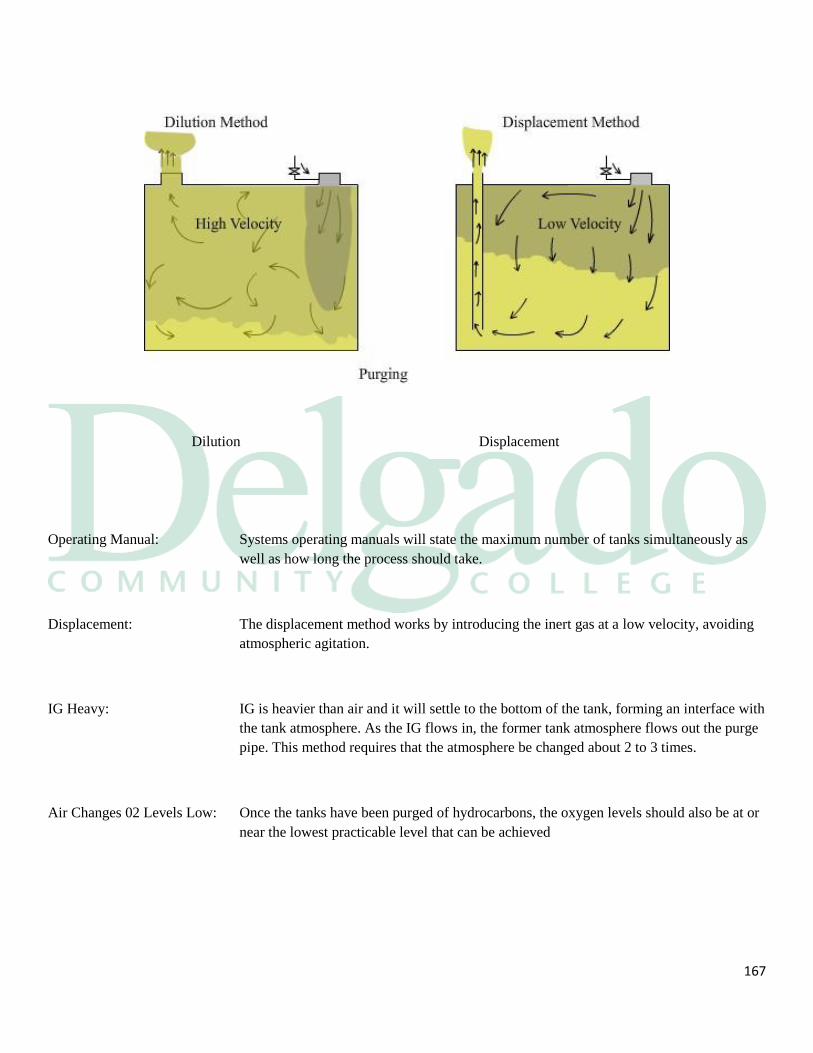
167
Dilution Displacement
Operating Manual: Systems operating manuals will state the maximum number of tanks simultaneously as
well as how long the process should take.
Displacement: The displacement method works by introducing the inert gas at a low velocity, avoiding
atmospheric agitation.
IG Heavy: IG is heavier than air and it will settle to the bottom of the tank, forming an interface with
the tank atmosphere. As the IG flows in, the former tank atmosphere flows out the purge
pipe. This method requires that the atmosphere be changed about 2 to 3 times.
Air Changes 02 Levels Low: Once the tanks have been purged of hydrocarbons, the oxygen levels should also be at or
near the lowest practicable level that can be achieved
168
Seal the Tank: When the purging is done you must secure the deck to keep the tanks sealed. You should
ensure that:
The purge pipes are closed tight
The ullage caps are secure
All the Butterworth plates are tight
Positive Pressure: Positive pressure must be maintained for the rest of the passage to preclude any
fresh air from entering the tanks.
Shutting Down: Shutdown procedures should be as follows:
All tank pressures are positive
All tank atmospheres are at 8% or lower 02
Secure the deck isolating valve
Open the vent to atmosphere valve
Secure the gas regulating valve
Secure the inert gas blowers
Secure the blower suction and discharge valves
Open the blower washing system as per manufacturer recommendations
Secure the flue gas valve
Keep the water supply to the scrubber
Insure the water supply remains going to the deck seal
Ballast Passage: You may have tank cleaning and repairs to do on the ballast leg. It is important to keep
the positive pressure of inerted gas in the cargo tanks that you achieved when purging the
tanks after discharge.
Re-purge: If the pressure falls below positive you will have to purge the tanks again.
Maintaining: Maintaining the atmosphere in the tanks is one of the more important safety functions. It
provides a safeguard against:
Fire; and
Explosion.
First Level: The first level of precautions against ignition hazard are the:
169
Smoking regulations
Hot work permits
Non-sparking devices
Second Level: Maintaining the tank atmospheres so that fire cannot be supported provides a second
level of protection.
Before Loading: Before loading begins, the tank atmospheres must have been brought below the 8%
oxygen level and the:
IG system will have been shut down; and the deck isolation valve closed
During Load: The IG pressure must be monitored closely during loading and the excess gas, displaced
by the incoming cargo, vented either to:
The atmosphere via the mast riser; or
Through the vapor emissions control system.
Pressure Falls: If the Person-In-Charge allows the inert gas pressure to fall too low then:
Loading must be suspended until the pressure has been brought above 100 mm
water gauge as per 46 CFR 32.53- 30; and
The oxygen content of the tanks ascertained.
Purging: Purging will have to be performed if any of the tanks contain above 8% oxygen before
loading may be resumed.
170
Loaded Passage: Most of the time atmospheric maintenance on the loaded passage consists of maintaining
a positive pressure on the tanks.
High Oxygen: If the oxygen level in a tank exceeds 8%, then that tank will have to be purged to bring
the level back within parameters.
COW Operations: The inert system must be fully operational when performing crude oil washing
procedures as per 33 CFR 157.164 with the tanks at 8% oxygen or below and with a
positive pressure in the tanks.
Regulations: Regulations for the fitting of IGS on barges are found in the:
SOLAS Convention of 1974, Chapter 11-2; and46 CFR 32.53.
IG Required: Almost all barges of 20,000 DWT and above must have an inert gas system and the
regulations call for inert systems on all:
New ship's crude oil carriers of 20,000 DWT and above
Existing product barges of 40,000 DWT and above
Existing product barges of 20,000 DWT and above up to 40,000 DWT that are
fitted with high capacity (60 m3/h and higher) tank washing machines
Barges, regardless of size, that are fitted with crude oil washing machines
IG Not Required: Existing product carriers of less than 40,000 DWT with low capacity tank washing
machines are not required to have inert gas systems.
171
6.7 Precautions When Using Inert Gas
Introduction: Inert gas poses several hazards both to personnel and the environment. Even though inert
gas greatly increases the operational safety of tank vessels, it is a hazard
Exhaust Gas: Inert gas is an exhaust gas from a combustion process, it is in the same category as
automobile exhaust. In many areas it is illegal to exhaust it into the atmosphere
Personnel: The personnel hazards with IG fall into two categories and they are:
The gas is non-breathable
It is an asphyxia
Warning: Never enter a tank that is inerted. Prior to entering a tank you must:
Purge the tank with fresh air
Test for 21% 02
Riser Height: The height of the mast riser or the exit velocity of the bullet valves helps minimize the IG
vapors that will appear on the deck.
The Scrubber: The scrubber and the waste water that it discharges present hazards to personnel. The
scrubber wastewater contains many contaminants and among them are:
172
Sulfur dioxide
Soot
Sulfur Dioxide: The sulfur dioxide will cause burns when dissolved in water.
Confined Space: The scrubber is a confined space and all precautions for confined space entry must be
taken before personnel enter the scrubber tower for inspection or maintenance.
Scrubber Leaks: The scrubber tower should be checked to ensure it is not leaking gasses to the atmosphere
it is in.
Contamination: To prevent cargo contamination, the IG branch line valves to tanks containing the
sensitive cargo may have to be kept closed or even blanked off.
Complications: This will complicate atmospheric maintenance during the loaded passage as it will be
necessary to:
Top off the IG in the majority of cargo tanks
Close the valves to them
Purge the IG line of any cargo vapors
Open the sensitive product tanks
Top them off with IG
Isolated them from the system again
Rust: When cargoes containing hydrogen sulfide are carried special hazard is created. In an
inerted tank, the hydrogen sulfide given off by the cargo can combine with iron oxide
already present in the tank. The resulting product is iron sulfide.
6.8 Ballasting and De-Ballasting
173
Clean ballast: Definitions Clean ballast is water with an oil content of less than 15 ppm.
Discharge: A discharge is any release of effluent or harmful substance, however
caused, from the vessel into the water and includes any:
Escape
Disposal
Spilling
Leaking
Pumping
Emitting
Emptying
An oily mixture is a liquid with any oil content, including:
Tank washings from oil tanks
Bilge slops
Oily wastes
Dirty ballast
Sludge
Oily Mixture: A special area is a sea area where the adoption of special mandatory methods for the
prevention of sea pollution by oil, NLS or garbage is required. These areas can be
found in:
Annex I of MARPOL for oil pollution
Annex II of MARPOL for NLS
Annex V of MARPOL for garbage
Special Area: The slop tank is the tank where oily mixtures generated on board are
transferred for:
Settling
Processing
Separating
Decanting
174
Cargo Monitor: The cargo monitor is designed to measure and record the oil content of cargo residues.
The monitor can:
Calculate the ppm of the discharged liquid
Calculate the rate of discharge
Shut down the discharge when the oil content exceeds the regulatory maximum
Segregated: Segregated ballast is the ballast water introduced into a tank that is completely separated
from the cargo and fuel oil systems and that tank is permanently allocated to the carriage
of ballast.
Dedicated Clean: Dedicated clean ballast is ballast carried in a tank that is set aside for the carriage of
ballast. The tank is not totally separated from the cargo system but is connected to the
least practicably numbers of cargo pumps and amount of pipeline as possible.
6.9 Requirements for Ballast
Introduction: The loading and discharge of ballast is one of the more important supporting operations
in vessel practice since it can take place in load ports, discharge ports and at sea. There
are many reasons for taking ballast, such as:
To enhance stability
To reduce hull stress and bring it within hull parameters
To improve vessel handling response
To meet draft restrictions
To meet air draft restrictions
Heavy weather
Minimum Draft: Most segregated ballast barges sailing today were converted from barges that had no
segregations when they were built. They carry just enough ballast to make the minimums
required in 33 CFR 157.1Ob. The formulae for these minimums are as follows:
The molded a mid-vessels draft will be no less than 2 meters plus 0.02 times the
length between perpendiculars in meters for vessels of 150 meters or more
The draft in meters at the forward and aft perpendiculars must correspond with
the amid vessels draft with a trim by the stern of no more than 0.015 times the
length between perpendiculars in meters
The minimum draft aft shall be enough to obtain full immersion of the propeller
175
Segregated: Segregated ballast is loaded and discharged during cargo operations. A ballast plan is still
required and requires close monitoring by the PIC. This ballasting will help you:
Maintain proper trim for stripping
Maintain an even keel for topping
Keep the vessel in the proper stress condition
Keep the vessel at the desired draft marks
The Plan: On segregated ballast barges, the ballasting is done concurrently with the cargo
operations. On the ballast section of the written plan, you would want to include:
When to start the ballast
What pumps you want to use
The amount of ballast to be loaded or discharged
The maximum drafts allowed during the operation
The maximum trim and stress tolerances
The sequence
Considerations: In running a concurrent cargo and ballast operation, you must consider the following:
Stripping or topping times will not be interfered with
The limitations of the manpower you have available
The rate your cargo and ballast pumps will do
Free surface
Non-segregated: On non-segregated ballast barges, ballasting is not done concurrently with the cargo
operation. Normally you must wait until you have received a dry certificate from the tank
inspector before you can start ballast. The planning is the same.
Differences: The big difference between the non-segregated ballast vessel and a segregated ballast
vessel is that you load and discharge the ballast through the cargo piping system. The
non-segregated ballast vessel is usually at a high hogging stress when in a very light
condition and is vulnerable to be blown off the dock in high winds. You would want to:
176
Start the ballast as soon as possible
Get the bow draft down as soon as you can
Hazards: The non-segregated ballast vessel presents some additional pollution hazards for
pollution control. Some of these are:
You are loading ballast through the cargo system;
It is possible to have a discharge of oil into the water when you open the sea
valve to start the ballast; and
You are mixing oil residues with ballast water creating a disposal problem.
The Oil Record Book
The Book: Each oil tanker of 150 gross tons and above, ship of 400 gross tons and above other than
an oil tanker, and manned fixed or floating drilling rig or other platform shall maintain an
Oil Record Book Part I (Machinery Space Operations). An oil tanker of 150 gross tons
and above or a non-oil tanker that carries 200 cubic meters or more of oil in bulk, shall
also maintain an Oil Record Book Part II (Cargo/Ballast Operations) as per 33 CFR
151.25.
NLS Book: A similar Cargo Record Book is required to be carried on board vessels carrying Noxious
Liquid Substances (NLS) as per 46 CFR 153.909.
Required Entries: The required entries are listed in the front of each book and MARPOL contains the
regulations concerning the required entries and they are:
Regulation 20 of Annex I for oil
Regulation 9 of Annex II for NLS
Part I: The required entries for machinery space operations in part I of the Oil Record Book are
as follows:
Ballasting or cleaning of fuel oil tanks
Discharge of dirty ballast or cleaning water from fuel oil tanks
Disposal of oily residues (sludge)
Discharge overboard or disposal otherwise of bilge water
Part II: The required entries for cargo/ballast operations in part II of the Oil Record Book for oil
barges are as follows:
177
Loading of oil cargo
Internal transfer of oil cargo during voyage
Unloading of oil cargo
Ballasting of cargo tanks
Ballasting dedicated clean ballast tanks
Cleaning of cargo tanks including crude oil washing
Discharge of ballast except from segregated ballast tanks
Discharge of water from the slop tank
Closing of all applicable valves or similar devices after the slop tank discharge
Closing of valves necessary for isolation of dedicated clean ballast tanks from
cargo and stripping lines after the slop tank discharge operations
Disposal of residues
NLS: Barges are required to keep a Cargo Record Book in lieu of Part II of the Oil Record
Book when they are carrying NLS cargo in bulk. The required entries are as follows:
Loading of cargo
Internal transfer of cargo
Unloading of cargo
Mandatory pre-wash
Cleaning of cargo tanks
Ballasting of cargo tanks
Discharge of ballast from cargo tanks
Accidental or other exceptional discharge
Controlled by authorized surveyor
Additional operational procedures and remarks
Signatures: Each entry in the Oil Record Book or Cargo Record Book must be signed by the officer
or officers in charge of the operation concerned and each completed page shall be signed
by the PIC Tankerman .
On Board: These books are required to be retained on the vessel for three years as per:
33 CFR 153.26 k for the Oil Record Book; and
46 CFR153.909 e-1 for the NLS Cargo Record Book.

178
179
6.10 Requirements for the Discharge of Ballast
Oily Discharge: The most common discharge of an oily mixture into the sea is the discharge of water
from the slop tank. A vessel must meet several requirements to discharge an oily mixture
legally and some of them are:
The vessel is not within a special area
The vessel is more than 50 nautical miles from the nearest land and the vessel is
proceeding enroute
The instantaneous rate of discharge of oil content does not exceed 30 liters per
nautical mile
The total quantity of oil discharged into the sea does not exceed:
o 1/15000 of the total quantity of the particular cargo of which the residue
formed a part for existing barges;
o 1/30000 of the total quantity of the particular cargo of which the residue
formed a part for new barges;
The vessel has in operation an oil discharge monitoring and control system
A slop tank arrangement as required by Regulation 15 of Annex I.
Not Allowed: Barges used to carry ballast water in cargo tanks but now carrying ballast in cargo tanks
is not allowed on SBT and DBT vessels under normal conditions as per 33 CFR 157.35.
When Allowed: The carriage of ballast in cargo tanks is allowed in those cases where it is necessary for
the purpose of securing the safety of a vessel or saving life at sea.
Regulation: Regulation 13 of Annex I of Marpol 73178 allows the taking of ballast in cargo tanks by
SBT and DBT barges in two circumstances:
On those rare voyages when weather conditions are so severe that, in the opinion of
the PIC Tankerman , it is necessary to carry additional ballast water in cargo tanks
for the safety of the vessel
In exceptional cases where the particular character of the operation of an oil vessel
renders it necessary to carry ballast water in excess of the quantity required as
segregated ballast, provided that such operation falls under the category of
180
exceptional cases as established by the IMO.
Complying: If you do carry ballast water in the cargo tanks, you must adhere to the regulations for the
discharge of an oily mixture into the sea and you should:
Obtain the interface to prove that separation has occurred
Ensure that the oil level is high enough in the tank so that it will not be
discharged
Start Up: Great care must be taken when starting to load ballast into a cargo tank. Residual oil in
the cargo pipelines might drain into the water when the valves for taking ballast are first
opened. A proper sequence of operations can prevent this discharge, such as the
following:
Strip the pumproom pipeline risers and drops to the slop tank
Drop all deck cargo lines into the tanks
Strip all deck pipelines into the slop tank
Keep the sea suction valve closed
Lineup all the valves necessary for taking the ballast
Start the pump
When there is a vacuum at the sea suction valve, open it
As the sea valve opens, speed up the pump
Once flow is established and the sea valve is fully open, the loading rate may be
regulated as needed
Ballast Planning: The PIC Tankerman is responsible for the amount of ballast to be taken. When
developing a ballast plan consideration should be given to several items such as:

181
The draft and trim requirements for departure
Air draft requirements
The requirements for stability and stress
Cleaning tanks for repairs
Cleaning tanks for normal maintenance
Heavy weather planning
Arrival draft requirements
In Compliance: The ballast plan must be discussed with the terminal at the Pre-transfer Conference. The
ballast plan must be written with all the regulations in mind and you should be able to
meet all of your requirements for a safe ballast voyage.
182
Section 7
Emergency Procedures
Introduction Failures and emergencies are an everyday part of life onboard the vessel. Day to day
operations require constant:
Vigilance
Preparedness
Situational awareness
Examples There are specific emergencies that are now covered in the Company Operations Manuals
(COM) and Oil Spill Response Plans (OSPR). Examples of failures and emergencies
requiring contingency planning include the following:
Communication failures
Emergency shutdowns
Oil spills
Fire
Collision
Grounding
Confined space rescue
Mooring breakaways
Equipment failure
Structural failure
The emergency discharge of cargo
Communication Communications is one of the most important things we do. During an emergency, events
must be communicated precisely. A communication failure can lead to an emergency or
compound an ongoing emergency.
Breakdown Whether it is verbal or written, communications can breakdown in the following areas:
183
Shore to vessel
Vessel to shore
Onboard the vessel
Procedures Communication procedures are incorporated into the COM and OSRP and outline:
The companies policies
Alternative communication methods
A contact list
Emergency Shut Down:
In the event of an emergency during unloading operations, the flow of cargo may be
stopped by pulling the remote shut down cable located near the center of the barge and
marked with a sign. The Tankerman PIC must verify the shutdown operates before each
transfer.
The Tankerman PIC shall discuss emergency shutdown procedures with the vessel or
facility prior to the transfer of cargo. This discussion should include:
Circumstances requiring the transfer to stop immediately
Primary and secondary means of communication
Valves to be closed, location of the shutdown cable, and other actions to be taken
in the event of an emergency
How long it will take for the shutdown to take effect (is it immediate or does it
take several minutes in order to avoid rupturing lines)
Communications:
Communications shall be established, between the terminal (or vessel) and the barge
before the transfer hose is hooked up. Communications must be maintained until the
transfer is complete and hoses are disconnected. PIC must routinely check
communication at least every 2 hours. If portable radio devices are used, they must be
intrinsically safe and meet the requirements of 46 CFR § 110.15-100(I) Class I, Division
I, Group D as defined in 46 CFR § 111.80
If at any time during transfer operations communications are interrupted, STOP ALL
184
TRANSFER OPERATIONS and do not resume until communications have been
reestablished.
The vessel's emergency shutdown as required by 33 CFR 155.780 is tested within 24
hours prior to the vessel beginning a discharge. This is covered in the COM and OSRP
and also should be:
Incorporated into a separate emergency drill
The crew will then know when it should be used
Shore EM The shore emergency shutdown required by 33 CFR 154.550 requires the shore to stop
the flow of cargo within 30 seconds. The vessel's PIC and shore PIC arrange for the test
of the shutdown at the start of the load. The means of this shutdown must be:
An electronic, pneumatic or mechanical linkage to the facility
Continuous voice communication to a person who can stop the flow of oil
Shutting Down The shutdown can be initiated by anyone concerned and all of the cargo team should be
trained in its use. After the shut down and the situation has been assessed by the PIC's, an
agreement to resume the operation can be completed
Cargo Spill A cargo spill would be covered in the COM and the OSRP with drills being held on a
monthly basis as per 33 CFR 15.1060 to simulate an oil spill.
Fire Drills Fire Drills shall be held weekly as per 46 CFR 78.17-50 and they should be conducted as
if a real fire existed. SOLAS in regulation 18, Part B-Chapter Ill recommends monthly
drills.
Collision The COM and OSRP would contain contingency plan for collision. There would be a
checklist for:
Ascertaining the damages
What you should do for damage control
Who to call
185
Equipment Failure The general category for equipment failure is drilled monthly on the vessel as per 33 CFR
155.1060 with specific quarterly equipment drills such as:
Steering gear loss
Loss of propulsion
Loss of power
Checklist Each equipment drill should have its own checklist.
Structure Failure Damage control drills are held on a quarterly basis. Each drill has the same type checklist
but with different items to drill with. The checklist would contain:
Emergency signals
Crew mustered at their stations
Emergency squad is briefed on the damage
Proper tools are gathered
Repairs simulated and completed
A safety watch is set
Emergency Discharge
of Cargo If the vessel or lives are imperiled; the regulations allow for an emergency discharge of
cargo. You will find this in the Company Operating Manual and the Oil Spill Response
Plan. There will be a checklist to
Tell you who to call
The information you will need
Cargo Spill Reporting PROCEDURES FOR REPORTING DISCHARGES OR OIL OR HAZARDOUS
MATERIAL 155.750(a) (9)
In the event of any emergencies on board, during or after cargo transfer operations,
immediate notice must be given to
In the event of a cargo spill into the water immediately notify:

186
1. The receiving vessel or facility to stop the transfer.
2. U.S. Coast Guard National Response Center (800) 424-8802
3. Company 24-Hour Emergency Contact
7.1 Contingency Planning
187
Planning It is necessary to develop a methodology of contingency planning that is applicable in
developing appropriate responses to failures and emergencies. Each emergency topic
would have:
Its own procedure
A corresponding drill
Items that should be performed
A contact list with home phone numbers
Home Office Today the shore side personnel take a much more active participation in the day to day
life of a working vessel. With the advent of ISM each home office has to implement
standards for:
Vessel board policies
Compliance with the regulations
Vessel's performance
Crew responsibilities
A designated person for the vessel's first emergency contact at the office 24 hours
a day
A home office chain of command with office and home phone numbers
Non-conformance reporting system
The office itself has to be in compliance
ISM The implementation of the ISM Code requires a compact to adopt a management system
that incorporates contingency planning with associated policy that support it.
Sources When these policies are being written, many different sources are used. Some of these
are:
Previous manuals
ISM code
USCG regulations
Their own experiences
System When the planning is done, the company will put together, a Company Standard
Operating Manuals. These manuals define the operational system and company policy
on:
Safety
188
Pollution
Vessel cargo operations
Bridge Watchkeeping
Engine room operations
Duties underway and in port
Near miss accidents
Dealing with non-conformities
Maintaining of vital systems
Drills and inspections
Emergency situations
Training Once manual has been developed, crew training and practice drills should be
implemented. Information gained from conducting these drills will provide:
How well they work
If any refinements need to be made to the operating manual
Vetting When the vessel is undergoing a vetting, the COM will be the centerpiece of this
inspection. The entire crew should know:
Where the manuals are kept
What their duties are
Where in the manual they can find their responsibilities and duties
What the company policies are
How to file a non-conformance report
What happens to those reports

189
190
7.2 Oil Spill Response Plan
Introduction Emergencies: One of the prime concerns of the PIC-Tankerman and crew is to operate the vessel in a
safe and efficient manner having due regard to the protection of the marine environment.
All vessels must conduct the following operations within the regulations:
Cargo
Tank cleaning
Ballasting
Bunkering
Garbage disposal
MARPOL: The International Convention for the Prevention of Pollution from Vessels (MARPOL
73/78) as amended is the international law for protecting the marine environment
MARPOL: Plan The requirement for the Vessel Response Plan is found in MARPOL Annex I,
chapter IV, Regulation 26.
Plan Required: A response plan is required per 33 CFR 155.1010 for any vessel that carries oil in bulk
and:
Is a U.S. flag vessel
Operates on the navigable waters of the U.S.
Transfers oil in a part or place subject to the jurisdiction of the U.S.
Response Plan: You should understand the purpose and the content of the response plan and this plan
should cover the following areas:
Identify equipment used onboard barges to prevent and respond to an oil spill
The procedures to respond to oil spills
191
The emergencies included in the plan are grounding, collision and fire and it must state
the crew responsibilities as per 33 CFR 155.1035 c-1 and where the following can be
found:
Damage stability information
Location of vessel plans
Oil transfer procedures
Emergency towing procedures
Sections: The Response Plan as per 33 CFR 155.1030 must be written in English and understood
by the crew and it should be divided into the following sections:
General information and introduction
Notification procedures
Vessel board spill mitigation procedures
Shore-based response activities
List of contacts
Training procedures
Drill procedures
Plan review and update procedures
Geographic specific appendix for each COTP zone in which the vessel operates
An appendix with vessel-specific information
Information: The general information in the plan must contain the following:
Vessel name, registry, call sign
Office phone number
Owner's and contact's phone numbers
COTP zones in which the vessel will operate
A table of contents for the record of changes
Notification: A checklist with all notifications in order of priority to be made by vessel board and
shore-based personnel is required. Notifications of a spill or a potential spill as per 33
CFR 155.1035 must include:
Which regulatory bodies to call
Identities of the persons to be notified of a discharge or substantial threat of a
discharge
The individuals to be notified by the vessel
The individuals to be notified by the shore-based personnel
192
Procedures for notifying the qualified individual
Description of primary and secondary means of communication
Information to be provided for the first and the follow-up notification
The Initial Call: The initial call must include at least the following information:
Vessel name and country of registry
Vessel call sign and official number
Date and time of incident
Location of incident
Intended track, course and speed of vessel
Radio stations guarded
Type and quantity of oil onboard
Nature and details of the incident
Details of pollution or threat of pollution
Weather and sea conditions
Vessel's size and type
Actions taken or planned to be taken by persons on scene
Current condition of the vessel
Number of crew and details of injuries, if any
Assessing a Spill: If a spill occurs, its severity must be assessed and a plan of action determined. The initial
assessment would include:
Type of oil, persistent or non-persistent
Quantity of pollution
The estimated size of the slick
Is the pollution moving, if so what direction
Can the vessel provide positive action
Is mitigation possible
The 2nd Call: With the second call as much information for the protection of the marine environment
must be relayed. This must include:
193
Additional details of the type cargo onboard
Additional details of the vessel's condition and ability to transfer cargo,
bunkers and ballast
Additional details of the quantity, extent and movement of the pollution and
whether the discharge is continuing
Any changes in the on-scene weather
Actions being taken with regard to the discharge and movement of the vessel
Order of Priority: If you have a spill you must prioritize how the spill will impact your surroundings. You
would look to the first priority first and work your way to the last in your report. The
order would be:
The immediate personnel safety and hazard potential
Vessel safety
Safety and impact on the environment
Economic impact to the company and owners
Mitigation: The procedures for the crew to mitigate or prevent any discharge of oil resulting
from vessel board operational activities are included in the Oil Spill Response Plan. The
responsibilities are identified by job title and the plan must address the following:
Transfer system leak
Tank overflow
Suspected cargo tank casualty
Hull leak casualty
Bunker spills
All other emergencies
Drills: Specific scenario mitigation drills are to be held monthly as per 33 CFR 155.1060 on the
vessel and you should:
Log the drill
Report the drill to the home office during the monthly communication drill
194
Equipment: Vessels 400 feet in length or greater must have appropriate equipment and supplies as per
33 CFR 155.205 for the containment and removal of onboard deck spills of at least 12
barrels including the following equipment:
Sorbents
Non-sparking hand scoops, shovels, buckets
Containers suitable for holding recovered waste
Emulsifiers for deck cleaning
Protective coating
Minimum of 1 non-sparking portable pump
Scupper plugs
EM Towing Oil Barges of 20,000 DWT to less than 50,000 DWT must provide an emergency
towing wire on one end of the vessel. Oil Barges of 50,000 DWT or more or any oil
vessel older than 20 year must provide an emergency towing wire on both ends of the
vessel.
Containment: Vessel as per 33 CFR 155.310 with a capacity of 250 or more barrels must have the
following:
Containment under each loading arm and manifold
4 barrels or more per hose with 12" id
Means of draining the loading arm without discharge of oil into the water
Combing around the cargo deck
At least 4" but not more than 8" high enclosing the deck
Is able to contain at least % barrel per hatch, manifold and connection in all
conditions of list and trim encountered during the loading operation
Mechanical means of closing each drain and scupper
During Transfer: During transfer operations, equipment and supplies must be set out and remain ready for
immediate use. Most vessels have set aside a locker or space for this purpose.
Internal Transfer: Vessels that do not have suitable piping to internally transfer cargo throughout its owns
tanks must carry:
195
Suitable hoses
Reducers for internal transfer within the vessel
Shore Response I: In an emergency one of your first calls would be to the QI. He would be responsible for:
Procedures for transferring responsibilities from vessel personnel to the shore-
based spill management team
Procedures for coordinating with the federal on-scene coordinator
List of Contacts: The name, location and 24 hour contact information for the following key individuals or
organizations must be included in the response plan, as follows:
Vessel owner or operator
Qualified individual or alternate
Applicable insurance representatives and surveyors
Agents
Persons to notify for activation of the oil spill removal organization
The spill management team
Persons to obtain additional response resources
Shore Structure: The organizational structure that will be used to manage the response actions would
include:
Command and control
Public information
Safety
Liaison with government
Spill response operations and planning
Logistics support and finance
Training: This plan must include the training that the crew having responsibilities must perform.
The plan must state where the training records are being retained, which must be:
Aboard the vessel
With the qualified individual
196
The U.S. location of the spill management team
Drills: The regulation 33 CFR 155.1060 calls for periodic drills, announced and
unannounced, to ensure the oil spill response plan will function properly. Some of these
drills are as follows:
Vessel onboard emergency procedures and qualified individual notification
drills must be conducted monthly
Shore based spill management and oil spill removal deployment is done
yearly
A full drill is done every 3 years
Plan Review: The plan must be reviewed annually by the owner or operator. The entire plan should be
submitted to the Coast Guard for re approval after the review along with any changes in
the plan such as:
Geographic specific appendices for each COTP zone in which vessel operates
List of areas the vessel will operate with appropriate COTP
Volume and type of oil now carried
Any other significant changes in the plan
Damage Stability: Vessels must have 24 hour access to shore based damage stability and residual structural
strength calculation programs. These programs must show the following:
Residual hull girder strength based on the reported extent of the damages
Residual stability when compartments are breached
Most favorable offload, ballast and cargo transfer sequence to improve the
situation
The bending and sheer stresses caused by pinnacle loads from grounding or
stranding
QI: Response plan must identify a qualified individual and at least one alternate and he must:
Speak fluent English
Be located in the U.S. 24 hours a day
Be familiar with implementing the response plan
Be trained in the responsibilities of the Q.I.
QI Authority: The Q.I. will be furnished with a document from the owners giving him full authority to:
197
Activate and engage in contracting with the oil spill removal organizations
Act as a liaison with federal on-scene coordinator (osc)
Obligate funds required to carry out the response activities
Organization QI: The company may designate the use of an organization as QI and an alternate QI and list
the company named in the response plan but they also must:
Specifically name a person as QI
Name a person as alternate QI
List them in the response plan - QI liability
The qualified individual is not responsible for:
o The adequacy of the response plan prepared by the company
o Obligating funds beyond the full authority contained in the designation
from the owner or operator
Geographic: The plan must have a specific appendix for each of the COTP zones covering:
All the geographic areas in the U.S. where the vessel intends to operate
The appendix must provide a port specific plan
Appendices: The appendix contains a list of vessel's characteristics which would include:
Capacities of all cargo, fuel, lube oil, ballast and fresh water tanks
Volume and types of oil cargo carried
Diagrams showing location of all tanks
General arrangement plans
Mid-vessels section plan
Cargo and fuel piping diagrams
Pumproom plan
Damage stability data
Location of cargo and fuel storage plan
198
Material safety data sheets for the cargo carried
Prevent Spills: Preventing spills from reaching the water will save a lot of paperwork and headache.
Some of this prevention is listed below:
Ensure all scuppers are securely plugged
Small deck spills are usually cleaned-up with oil-absorbent pads, rags and
"speedy dry" type sawdust
Large spills require immediate action
Casualty Report: As per 46 CFR 4.05, immediately after addressing the safety concerns, the owner, agent,
PIC Tankerman , operator or person in charge, shall notify the nearest Marine Safety
Office whenever a vessel is involved in a marine casualty consisting in:
An unintended grounding or striking of a bridge
An intended grounding or striking of a bridge that creates a hazard to navigation
A loss of main propulsion or steering gear
An occurrence that materially and adversely affecting the vessel's seaworthiness
A loss of life
An injury that requires professional medical treatment
An occurrence causing $25,000 property damage
Good Judgment: In case of emergencies according to 46 CFR 35.35-75, nothing in the regulations in this
subchapter shall be construed as preventing the senior officer present from pursuing the
most effective action in his judgment for rectifying the conditions causing the emergency
Section 8
Vapor Emissions Control
Purpose: Vapor emission control was instituted as a means of combating air pollution from barges
and oil terminals while handling petroleum oils and NLS cargoes.
199
IG: Pollution Inert gas is a combustion product and it falls into the same category as stack
emissions or automobile exhaust.
Hydrocarbons: Hydrocarbon vapors are:
A pollutant
Flammable
Toxic
Other Vapors: Other vapors given off by petroleum products are also toxic.
Recover Vapors: VEC was started to recover these emissions rather than let them to be continuously
emitted to the atmosphere.
Improved Air: By utilizing a totally enclosed load and discharge method, the pollution from barges and
the refineries is greatly improved.
Type Emissions: When a tank, either ashore or afloat, is being filled with product the atmosphere in the
tank is displaced. Without vapor emission control it must be vented outside to the
atmosphere. Some of those emissions would be:
Inert gas vapors
Hydrocarbon vapors
Any other impurity from the product
Principles: There are three basic principles of vapor emission control and they are:
Collection
Control
Processing
Collection: A vapor collection system is an arrangement of piping and hoses used to collect vapor
emitted from a vessel's cargo tanks and to transport the vapor to a vapor processing unit.
200
Control: A vapor control system is an arrangement of piping and hoses used to collect vapor
emissions collected from a vessel. It includes:
The vapor collection system
The vapor processing unit
Processing: A vapor processing unit means the components of a vapor control system that takes the
collected vapors from a vessel and either:
Recovers them
Destroys them
Disperses them
8.1 Hazards of Vapor Emission Control
Introduction: By controlling vapors you introduce another set of hazards to the transfer
operation. To control the vapors you must have a closed system and it becomes
imperative that you follow the correct procedures. Some of these hazards are as
follows:
Vapor over and under pressurization
Cargo tank overfill
Fire and explosion
Liquid condensate build up
Electrostatic discharge
Pressure: The connection to a vapor emission control system results in pressures within the
vessel’s vapor spaces being directly influenced by any changes that may occur in
the facilities system.
Avoiding Hazards: In order to avoid these hazards the vessel shall ensure:
The PN screens are clear of debris
The PN valves are working
That the maximum allowable loading rate is not exceeded
The pressures within the vapor system are constantly monitored
The high and low pressure audio and visual alarms were tested and are
201
working properly
Overfill Risk: The risks of overfilling a tank are much greater when close loading than when
open loading a vessel. To minimize this hazard the vessel shall ensure:
The closed gauge system was tested and is in good working order
The back-up gauge system was tested and is in good working order
The high level alarms were tested and are in good working order
The overfill alarms were tested and are in good working order
Explosion: During the transfer of hydrocarbon products there is always the danger of
explosion or fire and the inter-connection of the vapor systems between the
vessel and shore, introduces significant additional hazards.
Arrestor: A detonator arrestor fitted in close proximity to the terminal vapor connection
provides the primary protection from fire and explosion for the vessel and the
facility.
Other Methods: If the terminal system does not handle the vapors through a detonator arrestor,
they will continuously monitor the stream and include provisions for either:
Inerting the vapor stream
Diluting the vapor stream
Enriching the vapor stream
Condensate: Liquid condensate can build up in the vapor line and impede the passage of
vapors which can:
Build up the line pressures
Generate significant electrostatic charges on the water's surface
Low Point Drain: Frequent checking the low point drain for accumulated water ensuring that no
liquid is present helps minimize this hazard.
Electrostatic: Having an inert atmosphere will eliminate electrostatic discharge fears. There are
other procedures and fixtures that help alleviate this charge and they are as
follows:
202
A slow initial loading floe rate to cushion the bottom
Following the procedures for measuring and sampling for static
accumulating cargoes
The vapor piping is electrically bonded to the vessel's hull
The piping is electrically continuous
Insulating Flange: Large currents can flow between vessel and shore in electrically conducting pipe
work and flexible hose systems. An insulating flange breaks the electrical current
between the vessel and the terminal at the loading arm connection. According to
ISGOTT, the insulating flange is recommended for use in cargo connections
rather than bonding cables.
Connections: The terminal vapor connections should be electrically insulated from the vessel
vapor connection by the use of:
An insulating flange
A single section of insulating hose
Heavy Vapors: Petroleum based products emit vapors and for the most part they are toxic and
flammable. High vapor pressure products emit vapors that are heavier than air.
Some of these products are:
Crude oils
Motor gasoline
Aviation gasoline
Natural gasoline
Distillate feed stocks
Naphtha
Vapor Clouds: When these vapors are being discharge from a purge pipe they will settle down
from the pipe outlet and form into a cloud near the lowest horizontal surface they
can drift to.
Layering: If you have gas freed a cargo tank that had these products, the upper section of
the tank may be at 21% oxygen and you could have a hydrocarbon vapor cloud
sitting at the bottom of the tank reading 10% oxygen.
203
Know Migration: It is important that you know how the vapors migrate when you are ready to test
an atmosphere. The vapors can:
Form into pockets at the bottom after end of the tank
Pocket on one of the shelves in the tank
They can roam the deck, seeking a lower level
Multi-level Test: Before entering the tank you should test each tank opening at multiple levels for:
Oxygen content
Hydrocarbon content
Atmosphere: Oxygen should be at 21% and the hydrocarbon content less than 10% of the LEL.
8.2 Vapor Emission Control Regulations
Introduction: Tank vessels in U.S. waters must comply with the regulations set out in 33 CFR
154.800 and 46 CFR 39 if they are collecting the vapors emitted from a vessel's
cargo tanks through a vapor control system and those vapors being:
Crude oil
Gasoline blends
Benzene
The System: Each vessel that has a vapor collection system must have the following installed:
Permanent vapor collection piping
Closed cargo gauging system
High level alarms
An overfill alarms
Legal Transfer: Vapor may not be transferred from a vessel to a facility that does not:
Meet the requirements of 33 CFR 154.800
Have its letter of adequacy endorsed
Loading Rate: The facility and the vessel must agree on the rate the cargo will be loaded but in no
case shall the rate exceed:
80% of the total venting capacity of the vessel's pressure relief valves
The total vacuum relieving capacity of the vessel’s vacuum relief valves
The rate based on the pressure drop calculations at which the pressure at
any of the vessel's cargo tanks exceeds 80% of the relief valve's settings
Each system has defined rates in its operating manual
High Load: Vessels must not load cargo higher than 98.5% of the cargo tank's volume as per
46 CFR 39.30-1-e-1.
Isolating Valve: The IG isolating valve must be closed during the vapor transfer operation.
Alarm Test: The high level alarms and the overfill alarms must be tested within 24 hours prior
to the cargo transfer as per 46 CFR 39.40-1-k.
Open Gauge: A cargo tank must not be opened to the atmosphere during cargo transfer
operations except that it may be opened for gauging and sampling while the vessel
is connected to a vapor control system if the following conditions are met:
The cargo tank is not being filled
The tank pressure is reduced to atmospheric
You wait 30 minutes for a non-inerted tank before you gauge it
The cargo is not required to be closed gauged as per 46 CFR 151.05 and
46 CFR 153
For static accumulating cargoes, all metallic equipment used in gauging
and the sampling are electrically bonded to the vessel
8.3 Vapor Collection System Passive Components
Piping: A vessel's vapor connections will usually be found at the forward and after
ends of the cargo manifold on both sides. The vapor collection piping
installed on tank vessels must meet the following requirements:
The piping must be permanently installed
The connection must be as close as practicable to the cargo
manifold
The piping must be electrically bonded to the hull
The piping must be electrically continuous
There must be a means to isolate the inert gas supply from the
vapor collection system
The piping must not interfere with the operation of the cargo tank
venting system
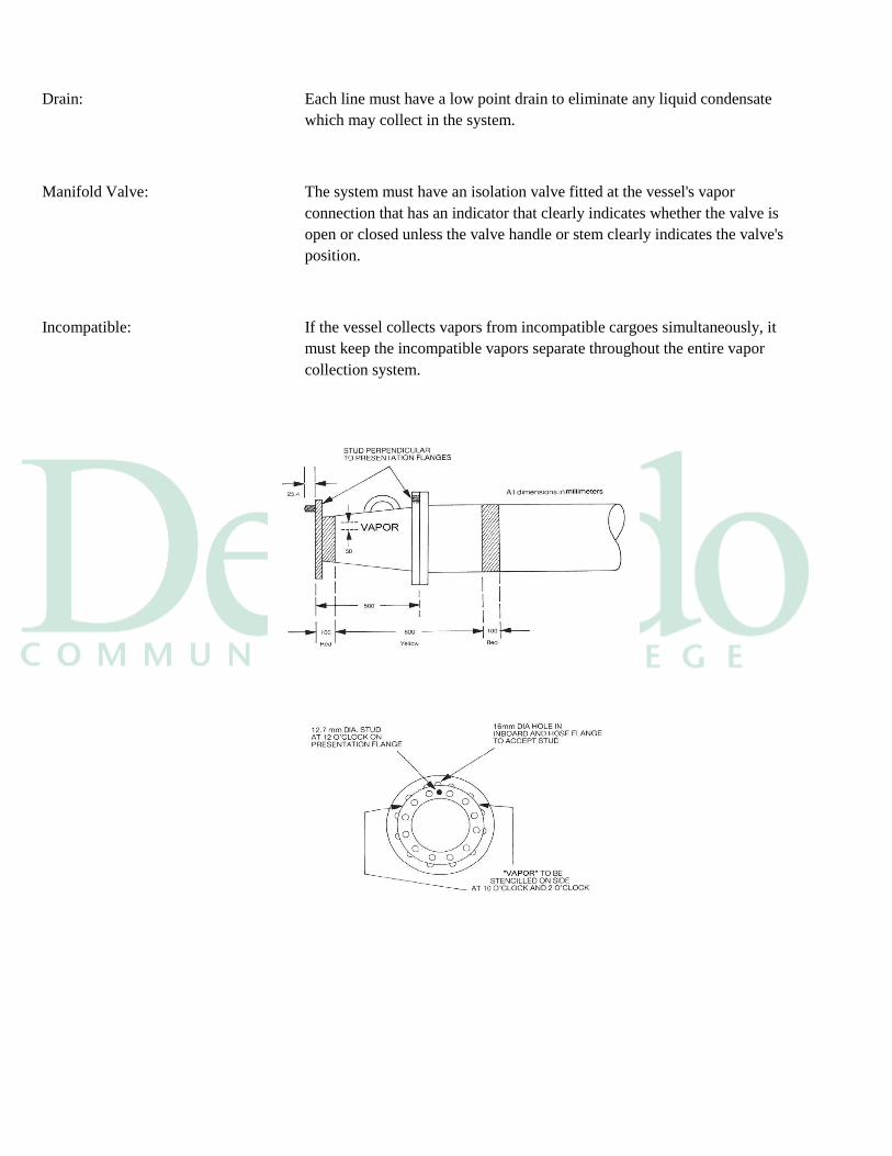
Drain: Each line must have a low point drain to eliminate any liquid condensate
which may collect in the system.
Manifold Valve: The system must have an isolation valve fitted at the vessel's vapor
connection that has an indicator that clearly indicates whether the valve is
open or closed unless the valve handle or stem clearly indicates the valve's
position.
Incompatible: If the vessel collects vapors from incompatible cargoes simultaneously, it
must keep the incompatible vapors separate throughout the entire vapor
collection system.
Vapor Control Hose Connection
Marking: The last meter of the piping, which includes the valve flange and a reducer, must
be marked as follows:
Painted in the sequence of red/yellow/red. The width of the red bands must
be 0.1 meter (0.33 foot) and the width of the middle yellow band must be
0.8 meter (2.64 feet)
Labeled with the word “VAPOR” painted in black letters at least 50.8
millimeters (2 inches) high
Vapor Stud: The valve flange and all the vapor recovery reducers must have a permanently
attached 0.5 inch diameter stud, at least 1 inch long, projecting outward from the
vapor connection flange face. The stud must be located at the 12 o'clock position,
midway between the bolt holes and in line with the bolt hole pattern as per 46 CFR
39.20-1 (h)
NLS Cargo: Vapor connections may be located in the vicinity of each tank in order to preserve
segregations of cargo systems, in lieu of common header piping for NLS cargoes.
Vapor Hose: If a vessel is carrying its own vapor transfer hose it must comply with the
following:
Have a design burst pressure of at least 25 psig
Have a maximum allowable working pressure of at least 5 psig
Be able to withstand at least 2.0 psi vacuum without collapsing or
constricting
Be electrically continuous at a maximum resistance of 10,000 ohms
Have flanges with a bolt hole arrangement complying with 150 pound
class ANSI 816.5 flanges
Have one or more 0.625 inch diameter holes in the flange, midway
between the bolt holes and in line with the bolt hole pattern
Be abrasion and kink resistant
Have the last meter of each end marked with red, yellow and red bands in
the same manner as the vapor collection pipeline
Have hose saddles which provide adequate support to prevent kinking or
collapse of the hose
Gauging System: Each cargo tank of a vessel that is connected to a vapor collection system must, as
per 46 CFR 39.20-3, be connected to a cargo gauging device which:
Provides for closed gauging and does not require opening the tank to the
atmosphere during cargo transfer operation
Allows the operator to determine the liquid level in the tank for the full
range of possible liquid levels
Indicates the liquid level in the tank at the location where the cargo
transfer is controlled
Protection: Each cargo tank of a tank vessel must be equipped with an intrinsically safe high
level alarm and a tank overfill alarm. These two alarms must:
Be independent of each other
Alarm in the event of a loss of electrical power
Be able to be checked at the tank for proper operation prior to each transfer
Be fitted with an electronic self-testing feature which monitors the
condition of the alarm circuitry and sensor
High Level Alarm: The high level alarm as per 46 CFR 39.20-9 Tank barge liquid overfill protection
A system meeting the requirements of 46 CFR 39.20-7 that
Includes a self-contained power supply
Is powered by generators on the barge
An intrinsically safe overfill control system that
Is independent of the cargo-gauging device required by 46 CFR 39.20-3(a)
Activates an alarm and automatic shutdown system at the facility overfill
control panel 60 seconds before the tank is 100 percent liquid-full during a
facility-to-vessel cargo transfer
Activates an alarm and automatic shutdown system on the vessel
discharging cargo 60 seconds before the tank is 100 percent liquid-full
during a vessel-to-vessel cargo transfer
Can be inspected at the tank for proper operation prior to each loading
Labeled “Connector for Barge Overflow Control System”
Overfill Alarm: The overfill alarm as per 46 CFR 39.20-7 d in each cargo tank of a vessel must:
Be independent of the cargo gauging system
Have audible and visible alarm indications that can be seen and heard
where the cargo transfer is controlled and in the cargo deck area
Be identified with the legend "tank overfill alarm" in black letters at least
50 mm high on a white background
Alarm early enough to allow the person-in-charge to stop the transfer
operation before the cargo tank overflows
Venting System : The separate cargo tank venting system required by 46 CFR32.55 must:
Be capable of discharging cargo vapors at 1.25 times the maximum
transfer rate
Not relieve at a pressure of less than 1.0 psig
Prevent a vacuum in the cargo spaces
Not relieve a vacuum of less than 0.5 psi below atmospheric pressure
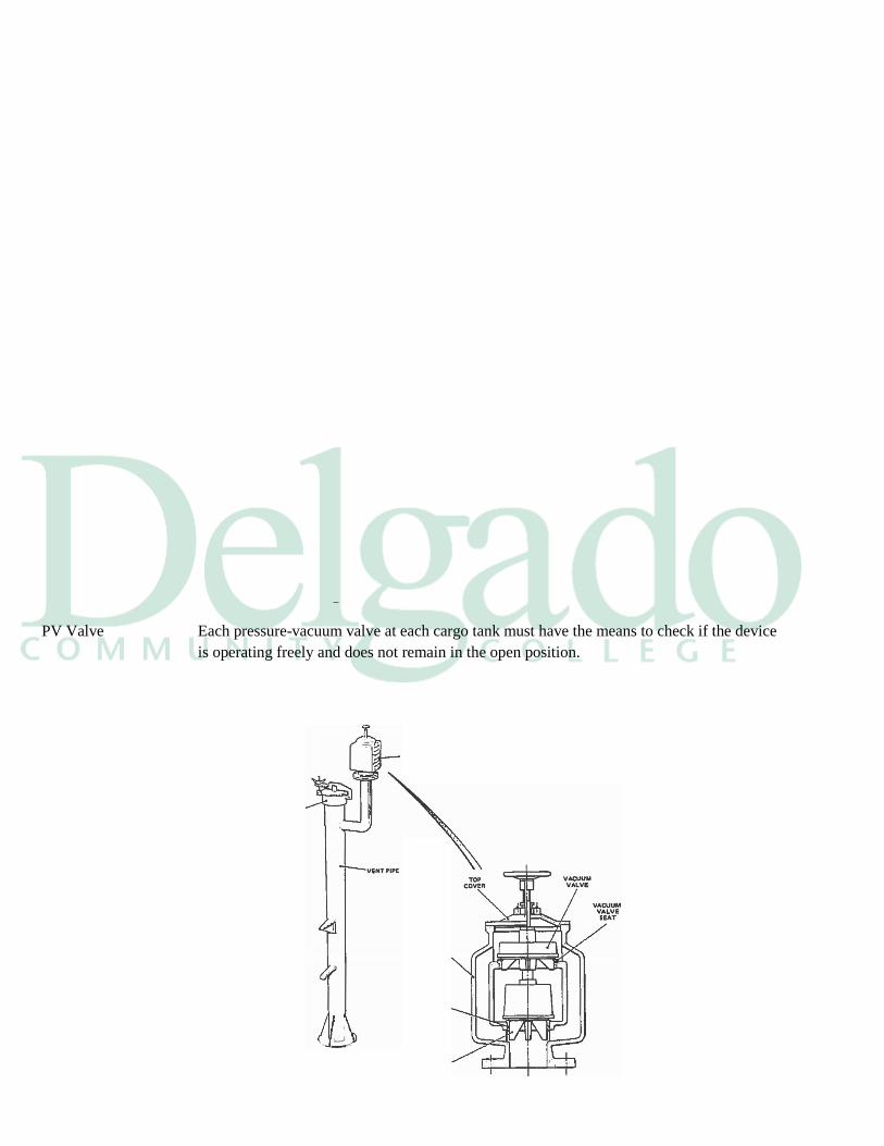
PV Valve Each pressure-vacuum valve at each cargo tank must have the means to check if the device
is operating freely and does not remain in the open position.
Pressure Each vessel vapor collection system must be fitted with a pressure sensing device that
senses pressure in the main vapor collection line, which:
Has a pressure indicator located on the vessel where the cargo transfer is controlled
Has a high pressure alarm
Has a low pressure alarm
The alarms are audible and visible on the vessel where the cargo transfer is
controlled
8.4 Vapor Control System Active Components
Shutoff Valve: A remotely operated cargo vapor shutoff valve must be installed in the vapor
collection line between the facility vapor connection and the nearest point where
any:
Inerting
Enriching
Diluting gas is introduced into the vapor collection line or
Where the detonation arrestor is fitted.
Shutoff rules this shut off valve must
Close within 30 seconds after the detection of a shutdown condition by a
component of this system
Close automatically if the control signal is lost
Activate an alarm when the signal to shutdown is received
Be capable of manual operation or activation
Have a local position indicator so the valve's position can be readily
determined
Overfill: Each facility that receives cargo vapor from a vessel with a gauging system
complying with 46 CFR 39.20-3, must have an overfill control panel on the dock
capable of powering and receiving an alarm and shutdown signal from the vessel's
cargo tank level sensor system that will:
Close the remotely operated cargo vapor shutoff valve
Activate an alarm that can be seen and heard to the vessel personnel and
the facility personnel
Have the means to electrically and mechanically test the alarms and
automatic shutdown systems prior to the commencement of transfer
Overpressure: A facility's vapor collection system must have the capacity for collecting cargo
vapor at a rate not less than 1.25 times the facility's maximum transfer rate for
cargo that requires vapor collection.
Stable Pressure: A facility vapor collection system must maintain the pressure in a vessel's cargo
tanks between 80% of the highest setting of any of the vacuum relief valves and
80% of the lowest setting of any of the vessel's pressure relief valves.
Alarms: Pressure sensing devises must be provided by the facility that will activate an
alarm when:
The pressure at the vapor connection exceeds the 80% of the vessel's
highest vacuum relief setting
The vacuum at the vapor connection falls below the lowest setting on the
vessel's vacuum relief valves
EM Shutdown: Pressure sensing devices must be provided which activates the emergency
shutdown system and closes the remotely operated cargo vapor shutoff valve
when:
The pressure at the vapor connection exceeds 2.0 psi or the pressure
agreed upon at the pre-transfer conference
The vacuum at the vapor connection falls below 1.0 psi or a value set at
the pre-transfer conference
Independent: The shutdown sensors must be totally independent from the alarm sensors.
Protection: A vapor control system that receives vapor from a vessel and processes that
vapor with a vapor destruction unit must:
Have a detonation arrestor located not more than 6 meters from the facility
vapor connection
Have an inerting, enriching or diluting system that meets the regulations in
33 CFR 154.824
Detonator: Each detonation arrestor used by vapor control systems must:
Be capable of arresting a detonation from either side of the device
Be acceptable to the commandant
Others: A vapor control system which uses inerting, enriching or diluting gas must be
capable of inerting, enriching or diluting the vapor collection line before receiving
cargo vapor.
Inlet to Unit: The inlet to a vapor recovery unit which receives cargo vapor that has not been
inerted, enriched or diluted must be fitted with one of the following:
A detonation arrestor
A flame arrestor
An explosion suppression system acceptable to the commandant
Seal & Valves: The inlet to a vapor destruction unit must:
Have a liquid seal

Have two quick closing stop valves installed in the vapor line
Destruction Unit: A vapor destruction unit must:
Not be within 30 meters of any tank vessel berth or mooring at the
facility
Have a flame or detonation arrestor fitted in the vapor line
Alarm and shutdown when a flame is detected on the flame or detonation
arrestor
Flame-out: When a vapor destruction unit shuts down or has a flame-out condition, the vapor
destruction unit control system must:
Close the quick closing stop valves
Close the remotely operated cargo vapor shutoff valve
Section 9
Gas Freeing
Why Gas Free Most vessels today have their tanks inerted so that the oxygen content in the tanks
is always at or below 8%. There are three main reasons why a vessel would want
to gas free and that is:
When changing to some cargo grades
When tanks need inspection or repairs
When preparing for the shipyard
Replacing IG To get from an inerted atmosphere to a gas free atmosphere, the:
Inert gas
Hydrocarbons
An inert gas hydrocarbon mixture has to be replaced with fresh air
Gas Freeing ISGOTT This The International Safety Guide For Oil Barges and Terminals describes tank
cleaning and gas freeing as the most hazardous period of vessel operations
replacement is called gas freeing.
USCG Gas free is described in 46 CFR 30.10-29 as the state of being free from dangerous
concentrations of flammable and toxic gases.
IG Dangerous IG is considered a dangerous concentration because of its asphyxiating
characteristic and it could contain hydrogen sulfide
Regulations According to 46 CFR 35.01-1a the provisions of Standard for the Control of Gas
Hazards on Vessels to be Repaired NFPA No. 306, published by the National Fire
Protection Association, shall be used as a guide in conducting the inspections and
issuance of certificates required by this section.
9.1 Gas Freeing Terms
Flammability Petroleum vapors are highly flammable and when mixed with at least 11% by
volume oxygen they will form explosive mixtures.
Toxic Petroleum vapors are also toxic. They contain the inherent capacity to produce
injury to a biological system.
Tank Entry Before you can safely put men in a tank that carried flammable and toxic materials,
you must get the vapors out of the tank.
Gas Free There are three levels of tank conditions for gas freeing purposes and they are:
Safe to load
Safe for men
Safe for hot work
Cargo Needs A tank that is required to be gas free for receiving cargo should be vented until
tests confirm that the hydrocarbon gas concentration throughout the tank to does
not exceed 40% of the LFL.
Safe for Men To have a tank safe for men as per NFPA 2-3.1means you have vented the tanks
until tests confirm that:
The hydrocarbon content throughout the tank is no more than 10% of the
LFL
There is sufficient oxygen (19.5% to 22%)
You have completed the appropriate toxic gas tests
Hot work Hot work is defined by the National Fire Protection Association, as any operation
or repair that utilizes:
Riveting
Welding
Burning
The use of power actuated fastening tools
Grinding
Drilling
Abrasive blasting, unless deemed otherwise by a marine chemist
Safe Hot Work Under the same NFPA 306 and ISGOTT guidelines the term safe for hot work,
requires for the following conditions to exist:
The oxygen content of the atmosphere shall not exceed 22% percent by
volume
The concentration of flammable materials in the atmosphere shall be less
than 10% of the LFL
Residues and scale shall be cleaned sufficiently to prevent the spread
of fire
The adjacent space atmospheres are purged of hydrocarbons, down to 2%
by volume
The adjacent spaces are kept inerted and secure
The adjacent spaces and the space shall be sufficiently cleaned of residues
or scale to prevent the spread of fire
Adjacent Spaces An adjacent space is a particular concern when you are going to perform hot work
in and enclosed space. NFPA306 defines an adjacent space as those spaces in all
directions from subject space, including all points of contact, comers, diagonals,
decks, tank tops and bulkheads.
9.2 Gas Freeing Operation and Equipment
Planning: Before you gas free a tank you will have to write a cleaning plan in order to get to
your objective. This plan should include the following:
Which tanks need to be butterworthed
The method of purging the hydrocarbons
The line flushing you want done
The number of Butterworth hoses to be used
The pressure and temperature for the wash water
The length of time for the drops
The distance for each drop
Stripping instructions
The method of blowing air into each tank
Purging: If the cargo tanks were inerted and you used the inert system throughout the
discharge, you must purge the hydrocarbon content of the tanks down to below 2%
by volume before you start the wash
Tank Washing: Tank washing is the first step of the gas freeing operation. It is necessary to
remove the free light oils from the cargo tank through the use of tank cleaning
machines and the line flush.
Scale & Gas: In gasoline and other light oil products, the oil will remain soaked into the scale or
behind it after the discharge. This residual oil will regenerate hydrocarbon vapors
in the tank if they are not removed.
Loose Scale: The loose scale will be knocked down during the tank washing by the high
pressure stream hitting them.
Portable: With portable tank cleaning machines, a pressure of a 120 psi and a water
temperature of 120°F should be used when cleaning coated tanks. (see tank
cleaning module)
Other Machines: Higher pressures and temperatures may be needed then those stated above when:
Fixed machines are used
When tank coatings have failed or are non-existent
Tank Clear: After you have washed the tank, it should be free of oil and debris.
development the general procedures for gas freeing tanks set forth by ISGOTT
were developed through studying the history of vessel explosions and by
regulation.
Isolation Fans: When a tank has been inerted before starting to gas free, it should be isolated from
tanks you are not going to gas free.
IG Fans: When either portable fans or fixed fans connected to the cargo pipeline system are
used to introduce air into the tank, the tank's IG inlet should be isolated and closed.
If you are going to use the IG fans with fresh air to gas free, then the:
IG line back to the inert gas source must be isolated and closed
The IG inlets into each tank being kept inerted must be isolated and closed
Tank Covers: The lids of all tank trunks should be kept closed until the ventilation of the
individual tank is about to commence for:
Inerted
Non-Inerted vessels
Portable Fans: The portable fan is designed to be move about the vessel and is used primarily on
the deck tank cleaning openings and their construction materials should be such
that no hazard of incendiary sparking arises if the impeller touches the inside of the
casing.
Bonded: These fans must be electrically bonded to the vessel's deck.
Fan Capacity: The capacity and penetration of portable fans should be such that the entire
atmosphere of the tank on which the fan is employed can be made non-flammable
in the shortest possible time.
Power Source: Portable fans or blowers should only be used if they are driven by:
Hydraulics
Pneumatics
Steam
IG Fans: Where cargo tanks are gas freed by means of one or more permanently installed IG
blowers, all connections between the cargo tank system and the blowers should be
blanked off when they are not in use.
Flush Pipes: Ventilation All the cargo piping must be flushed with clean seawater before using
permanent blowers
Vapor Entry: Central air conditioning or mechanical ventilating systems should be adjusted to
prevent the entry of petroleum gases into the living spaces during gas freeing
operations.
Inert Purging: If vapor entry of the living spaces should occur:
The air conditioning system should be shut down
Vent intakes covered or closed
A/C window units must unplugged
Have their intakes covered
Change to Air: Under SOLAS Regulation 59 tanks that are equipped with an inert gas system
must be purged of hydrocarbon vapors through its venting system with IG. The
inlet of the purge pipe may be located either at either:
Deck level
At no more than 1 meter above the bottom of the tank
Have an exit velocity of at least 20 meters per second at least 2 meters
above the deck
Outlet Position: IG purging must continue through the system until the remaining vapors in the
tank fall below 2% by volume and then gas freeing may take place at the deck
level with air.
Non-Inert Purging: On non-inerted vessels, the vapors shall be purged through the vessel's venting
system and the:
Outlets must be at least 2 meters above the tank deck level
Vertical efflux velocity is at least 30 meters per second
You vent with this method until the vapors are at 30% of the LFL
On individual cargo tanks the gas outlet pipe shall be positioned as far as
practicable from the inert gas or air inlet.
Connector: If there is a connection fitted between the inert gas supply mains and the cargo
piping system shall be made to ensure an effective isolation because of the large
pressure difference which may exist between the systems . This shall consist of:
Two valves with an arrangement to vent the space between the valves
A spool piece with associated blanks
Valves: If the valves are used, the valve on the cargo main side shall be a non-return valve
with a positive means of closure.
Openings Gas freeing involves the escape of gas at deck level. The degree of ventilation and
number of openings should be controlled to produce an exit velocity sufficient to
carry the gas clear of the deck.
Light Winds: If wind conditions are too light to carry vented gases away from the vessel the gas
freeing operation :
Should be stopped; until
The wind is able to break any heavy concentrations of the gases and carry
them away from the vessel.
Vapor Clouds: Hydrocarbon gases are heavier than air and will flow like a liquid around vent
openings forming vapor clouds.
Inert Gas: Inert gas is also heavier than air and only slightly lighter than the hydrocarbon
vapors.
Grounded: Portable blowers become static accumulators and must be grounded to the vessel
before use.
Horn Blower: Horn type gas ejectors should be avoided in gas freeing a space for entry if the air
is supplied to this blower by a diesel compressor . The air could be contaminated.

Dilution Method: The dilution method forces air into the bottom of the tank and out through the deck
opening. The blowers must have enough force to ensure air flow to the bottom of
the tank.
Air Column: This will require a column of air, moving at a rate of 30 to 40 meters per second
from the blower's exhaust point.
Mixture Purged: Air mixes with the gases in the tank and both are forced out tank openings at the
deck level that should be located at the furthest distance form were the blowers are
located.
Fresh air is blown in by a fan on the tank deck.
Testing: This process should be continued until you have tested the air leaving the tank at:
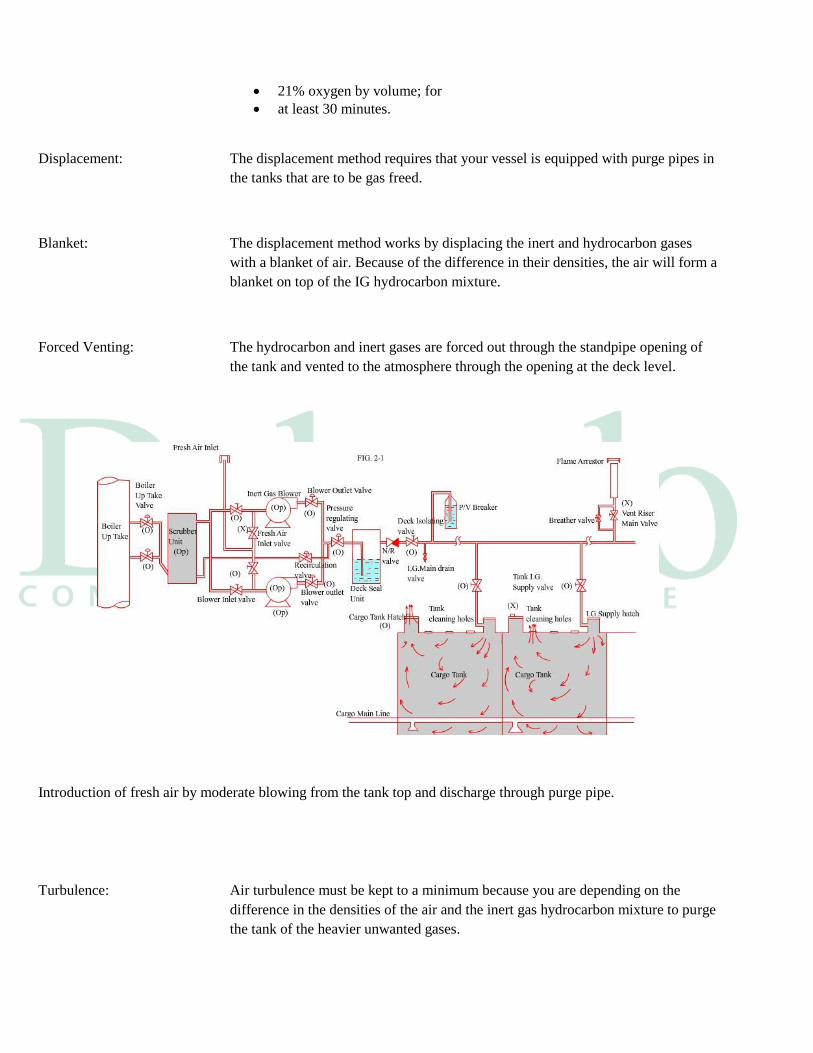
21% oxygen by volume; for
at least 30 minutes.
Displacement: The displacement method requires that your vessel is equipped with purge pipes in
the tanks that are to be gas freed.
Blanket: The displacement method works by displacing the inert and hydrocarbon gases
with a blanket of air. Because of the difference in their densities, the air will form a
blanket on top of the IG hydrocarbon mixture.
Forced Venting: The hydrocarbon and inert gases are forced out through the standpipe opening of
the tank and vented to the atmosphere through the opening at the deck level.
Introduction of fresh air by moderate blowing from the tank top and discharge through purge pipe.
Turbulence: Air turbulence must be kept to a minimum because you are depending on the
difference in the densities of the air and the inert gas hydrocarbon mixture to purge
the tank of the heavier unwanted gases.
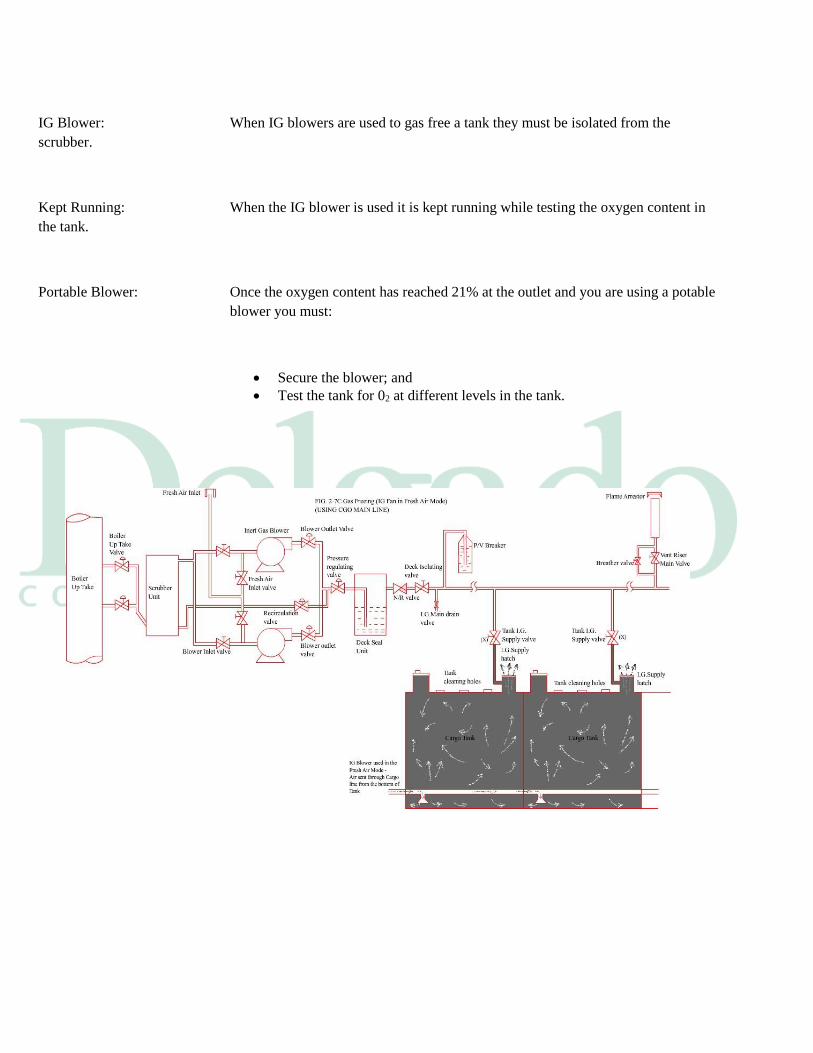
IG Blower: When IG blowers are used to gas free a tank they must be isolated from the
scrubber.
Kept Running: When the IG blower is used it is kept running while testing the oxygen content in
the tank.
Portable Blower: Once the oxygen content has reached 21% at the outlet and you are using a potable
blower you must:
Secure the blower; and
Test the tank for 02 at different levels in the tank.
9.3 Gas Freeing Precautions
Tank Monitoring: The blowers should always be running when men are working in the tanks and the
tank atmosphere should be constantly monitored for the unexpected release of gas.
Check Flow: Care must be taken to insure that the airflow into the tank is effecting the entire
tank and just not the atmosphere at the top of the tank.
Short Circuit: Short circuiting is when:
The air being injected into the tank is flowing across the top of the tank;
Then out of the vent at deck level; and
Has little impact on the rest of the tank's atmosphere.
Check Levels: Tank reading must be taken at different levels within the tank to ensure that proper
gas freeing has taken place.
Isolation: You must ensure the tank is properly isolated and the adjacent tanks and spaces
are in the proper condition for the operation you will be doing.
Deck Control: You must maintain control of the deck throughout the entire operation. The
condition of the deck should not deviate from what you planned from the time you
start gas freeing until you are finished. You should:
Utilize the lock out tag out procedures on the valves you do not want
opened
Set up a control area with boundaries
Designate a watch to ensure the area remains secure
Allow no other work to be done in the control area. The control area can
be the entire deck or one tank
When finished the person in charge shall designate when the condition of
the deck can be changed and when the gas freeing is done
9.4 Tank Cleaning
____________________________________________________________________________________________
___
General This Section deals with procedures and safety precautions for cleaning cargo tanks
after
the discharge of volatile or non-volatile petroleum carried in non-gas free, non-
inert or
inert tanks. Guidance is also given on the cleaning of contaminated ballast spaces.
Tank Washing
Risk Management All tank washing operations should be carefully planned and documented.
Potential hazards relating to planned tank washing operations should be
systematically identified , risk assessed and appropriate preventive measures put
in place to reduce the risk to as low as reasonably practicable.
In planning tank washing operations, the prime risk is fire or explosion arising
from simultaneous presence of a flammable atmosphere and a source of ignition.
The focus therefore should be to eliminate one or more of the hazards that
contribute to that risk, namely the sides of the fire triangle of air/oxygen, ignition
source and fuel.
Inert Tanks The method that provides the lowest risk is washing the tank in an inert
atmosphere. The
inert condition provides for no ambiguity; by definition, to be deemed inert, the
tank
MUST meet the SOLAS requirement for inerting of the cargo tanks and reducing
the
oxygen content of the atmosphere in each tank to a level at which combustion
cannot be
supported.
Failure to prove through direct measurement that the tank is inert means, by default
, that the tank MUST be considered to be in the non-inert condition.
Non-Inert Tanks In ships that do not have access to inert gas, either through on board facilities (e.g.
IGS
plant) or shore supply, is only possible to address the 'fuel' and the 'sources of
ignition'
sides of the fire triangle. In a non-inert condition, there are no physical barriers that
will
ensure elimination of these two hazards individually. Therefore, the safety of tank
washing in the non-inert condition depends on the integrity of equipment, and
implementation of strict procedures to ensure these two hazards are effectively
controlled.
Non-inert cargo tank washing should only be undertaken when two sides of the fire
triangle are addressed by a combination of measures to control both the
flammability of the tank atmosphere and sources of ignition.
It is recommended that all tankers that operate in the non-inert mode incorporate
within their design and equipment the ability to mechanically ventilate cargo tanks
concurrently with tank washing, in order to control tank atmospheres.
Supervision and Preparation A Responsible Officer must supervise all tank washing operations.
All crew involved in the operation should be fully briefed by the Responsible
Officer on the tank washing plans, and their roles and responsibilities prior to
commencement.
All other personnel on board should also be notified that tank washing is about to
begin and this notification must in particular be extended to those on board not
involved directly in the tank washing operation but who, by virtue of their own
concurrent tasks, may impact upon the safety of the tank washing operation.
Preparation Both before and during tank washing operations, the Responsible Officer should be
satisfied that all the appropriate precautions set out in Chapter 4 are being
observed. If
craft are alongside the tanker; their personnel should also be notified and their
compliance
with all appropriate safety measures should be confirmed.
Before starting to tank wash alongside a terminal, the following additional
measures should be taken:
The appropriate personnel ashore should be consulted to ascertain that conditions
on the jetty do not present a hazard and to obtain agreement that operations can
start.
The method of tank washing utilized on board a tanker is dependent on how the
atmospheres in the cargo tanks are managed and will be determined by the
equipment fitted to the vessel.
Tank Atmospheres Tank atmospheres can be either of the following:
Inert This is a condition where the tank atmosphere is known to be at its lowest risk of
explosion by virtue of the atmosphere being maintained at all times non-flammable
through the introduction of inert gas and the resultant reduction of the overall
oxygen content in any part of any cargo tank to a level not exceeding 8% by
volume while under a positive pressure.
Non-Inert A non-inert atmosphere re is one in which the oxygen content has not been
confirmed to be less than 8% by volume.
In recognition that tank washing and gas freeing operations in non-inert
atmospheres are considered to present a likelihood of increased risk, additional
control measures are required to reduce the risk of operations to as low as
reasonably practicable. These control measures MUST address two sides of the fire
triangle namely:
Tank Washing Washing in an Inert Atmosphere
During tank washing operations, measures must be taken to verify that the
atmosphere in the tank remains non-flammable (oxygen content not to exceed 8%
by volume) and at a positive pressure.
Washing in a Non-Inert Atmosphere
Non-inert cargo tank washing should only be undertaken when both the source of
ignition and the flammability of the tank atmosphere are controlled. To achieve
this, the following precautions to control 'sources of ignition' and 'fuel' MUST be
taken for tank washing operations in a non-inert atmosphere condition.
Before Washing
The tank bottom should be flushed with water so that all parts are covered,
and then stripped. This flush should be undertaken using the main cargo
pumps and lines. Alternatively, permanent pipework extending the full
depth of the tank should be used. This flush should not be undertaken
using the tank washing machines.
The piping system, including cargo pumps, crossovers and discharge lines,
should also be flushed with water. The flushing water should be drained to
the tank designed or designated to receive slops.
The tank should be ventilated to reduce the gas concentration of the
atmosphere to 10% or less of the Lower Flammable Limit (LFL). Gas tests
must be made at various levels and due consideration should be given to
the possible existence of pockets of flammable gas, in particular in the
vicinity of potential sources of ignition such as mechanical equipment that
might generate hot spots, e.g. moving parts such as found in-in tank
(submerged) cargo pump impellors.
Tank washing may only commence once the tank atmosphere reaches 10%
or less of the LFL.
During Washing
Atmosphere testing should be frequent and taken at various levels inside
the tank during washing to monitor the change in LFL percentage.
Consideration should be given to the possible effect of water on the
efficiency of the gas measuring equipment and therefore to suspension of
washing to take readings.
Mechanical ventilation should, whenever possible, be continued during
washing and to provide a free flow of air from one end of the tank to the
other.
The ability to mechanically ventilate concurrent with tank washing is
recommended but, where mechanical ventilation is not possible, the
monitoring of the tank atmosphere should be more frequent as the
likelihood of rapid gas build up is increased.
The tank atmosphere should be maintained at a level not exceeding 35%
LFL. Should the gas level reach 35% LFL at any measured location within
a tank, tank washing operations in that individual tank MUST immediately
cease.
Washing may be resumed when continued ventilation has reduced and is
able to maintain the gas concentration at 10% or less of the LFL.
When cleaning a tank by the Butterworth process, you should begin to
pump out the slops when the process is started.
Precautions for Tank Washing
Portable Tank Washing Machines and Hoses
The outer casing of portable machines should be of a material that will not give
rise to an incendive spark on contact with the internal structure of a cargo tank.
The coupling arrangement for the hose should be such that effective bonding can
be established between the tank washing machine, the hoses and the fixed tank
cleaning water supply line.
Washing machines should be electrically bonded to the water hose by means of a
suitable connection or external bonding wire.
When suspended within a cargo tank, machines should be supported by means of a
natural fiber rope and not by means of the water supply hose.
Portable Hoses for Use with both Fixed and Portable Tank Washing Machines
Bonding wires should be incorporated within all portable tank washing hoses to
ensure electrical continuity Couplings should be connected to the hose in such a
way that effective bonding is ensured between them .
Hoses should be indelibly marked to allow identification. A record should be kept
showing the date and the result of electrical continuity testing.
Testing of Tank Cleaning Hoses
All hoses supplied for tank washing machines should be tested for electrical
continuity in a dry condition prior to use, and in no case should the resistance
exceed 6 ohms per meter length.
Tank Cleaning Concurrently with Cargo Handling
As a general rule, tank cleaning and gas freeing should not take place concurrently
with cargo handling. If for any reason this is necessary, there should be close
consultation with, and agreement from, both the Terminal Representative and the
port authority.
Free Fall It is essential to avoid the free fall of water or slops into a tank. The liquid level
should
always be such that the discharge inlets in the slop tank are covered to a depth of at
least
one meter to avoid splashing. However, this is not necessary when the slop and
cargo
tanks are fully inerted.
Spraying of Water The spraying of water into a tank containing a substantial quantity of static
accumulator
oil could result in the generation of static electricity at the liquid surface, either by
agitation or by water settling. Tanks that contain static accumulator oil should
always be
pumped out before they are washed with water, unless the tank is kept in an inert
condition.
Use of Chemicals in Tank Cleaning Wash Water
Constraints on the use of chemicals in tank cleaning wash water will depend on the
type of tank atmosphere.
If tank cleaning chemicals are to be used, it is important to recognize that certain
products may introduce a toxicity or flammability hazard. Personnel should be
made aware of the
Threshold Limit Value (TLV) of the product. Detector tubes are particularly useful
for detecting the presence of specific gases and vapors in tanks. Tank cleaning
chemicals capable of producing a flammable atmosphere should normally only be
used when the tank has been inerted
Use of Chemicals for Local Cleaning of Tanks
Some products may be used for the local cleaning of tank bulkheads and blind
spots by hand wiping, provided the amount of tank cleaning chemical used is small
and the personnel entering the tank observe all enclosed space entry requirements.
In addition to the above, any manufacturer's instructions or recommendations for
the use of these products should be observed .Where these operations take place in
port, local authorities may impose additional requirements.
A Material Safety Data Sheet (MSDS) for tank cleaning chemicals should be on
board the ship before they are used and the advice on any precautions to be taken
should be followed.

Removal of Sludge, Scale and Sediment
Before the removal by hand of sludge, scale and sediment, the tank atmosphere
must be confirmed as safe for entry, with appropriate control measures
implemented to protect the safety and health of personnel entering the space. The
precautions described in Section 10.9 should be maintained throughout the period
of work.
As far as possible, tank cleaning, particularly in the initial stages, should be carried
out by methods other than hand hosing. Such methods may include, but not be
limited to, using portable machines, the use of detergents, or washing the bottom
of the tank with water and detergent. Hand hosing should only be permitted for
small areas of contamination or for final cleaning. Whichever method is used, the
tank washings must always be handled in accordance with MARPOL regulations.
After a machine or detergent wash, prior to entry for final hand hosing, the tank
must be ventilated until readings at each sampling point indicate that the
atmosphere meets the 'safe for entry' criteria in Chapter 10. Suitable control
measures should be implemented to protect the safety and health of personnel
entering the space.

Section 10
Stability & Trim
Stability-Concepts and Definitions
Introduction: Stability, trim, and stress calculations continue to be one of the most important and
challenging jobs that the chief mate has on a vessel. These calculations go hand in
hand with the cargo load plans.
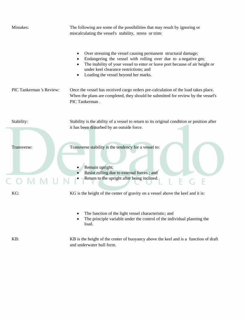
Mistakes: The following are some of the possibilities that may result by ignoring or
miscalculating the vessel's stability, stress or trim:
Over stressing the vessel causing permanent structural damage;
Endangering the vessel with rolling over due to a negative gm;
The inability of your vessel to enter or leave port because of air height or
under keel clearance restrictions; and
Loading the vessel beyond her marks.
PIC Tankerman 's Review: Once the vessel has received cargo orders pre-calculation of the load takes place.
When the plans are completed, they should be submitted for review by the vessel's
PIC Tankerman .
Stability: Stability is the ability of a vessel to return to its original condition or position after
it has been disturbed by an outside force.
Transverse: Transverse stability is the tendency for a vessel to:
Remain upright;
Resist rolling due to external forces ; and
Return to the upright after being inclined.
KG: KG is the height of the center of gravity on a vessel above the keel and it is:
The function of the light vessel characteristic; and
The principle variable under the control of the individual planning the
load.
KB: KB is the height of the center of buoyancy above the keel and is a function of draft
and underwater hull form.
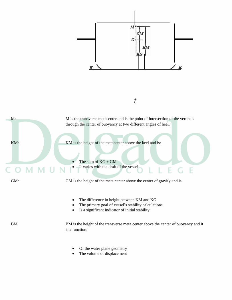
t
M: M is the transverse metacenter and is the point of intersection of the verticals
through the center of buoyancy at two different angles of heel.
KM: KM is the height of the metacenter above the keel and is:
The sum of KG + GM
It varies with the draft of the vessel
GM: GM is the height of the meta center above the center of gravity and is:
The difference in height between KM and KG
The primary goal of vessel’s stability calculations
Is a significant indicator of initial stability
BM: BM is the height of the transverse meta center above the center of buoyancy and it
is a function:
Of the water plane geometry
The volume of displacement
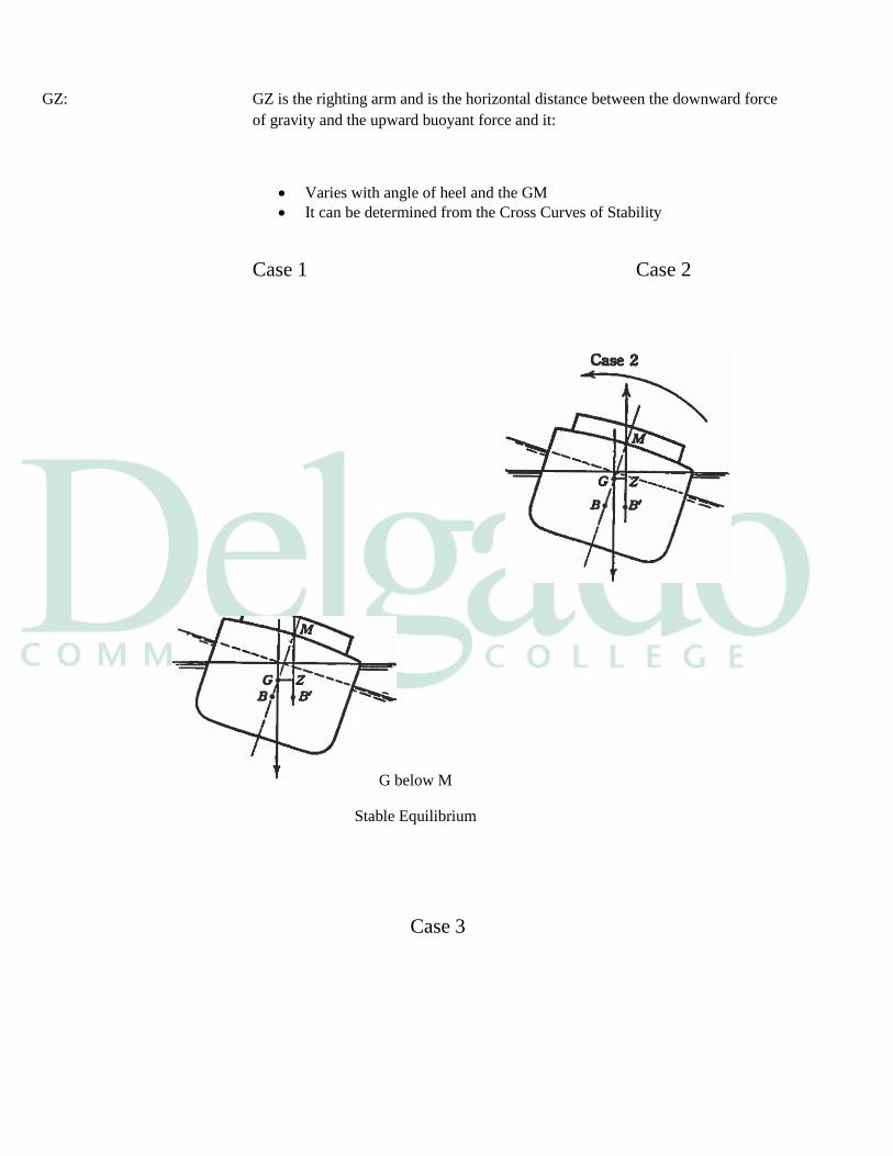
GZ: GZ is the righting arm and is the horizontal distance between the downward force
of gravity and the upward buoyant force and it:
Varies with angle of heel and the GM
It can be determined from the Cross Curves of Stability
Case 1 Case 2
G below M
Stable Equilibrium
Case 3
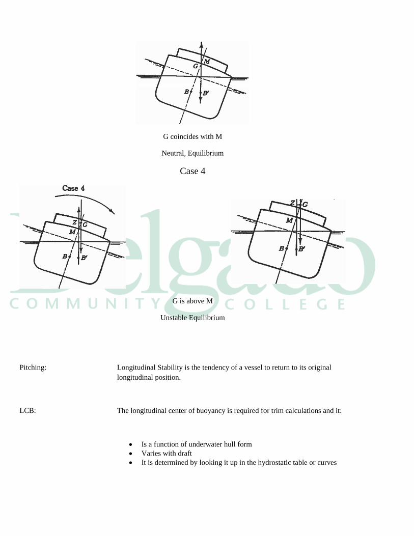
G coincides with M
Neutral, Equilibrium
Case 4
G is above M
Unstable Equilibrium
Pitching: Longitudinal Stability is the tendency of a vessel to return to its original
longitudinal position.
LCB: The longitudinal center of buoyancy is required for trim calculations and it:
Is a function of underwater hull form
Varies with draft
It is determined by looking it up in the hydrostatic table or curves
LCF: The longitudinal center of floatation is the tipping center where the vessel:
Trims about
Is a function of water plane area
Free Surface: Whenever the surface of a liquid within a vessel is free to move, the condition
known as free surface is present. Free surface can:
Reduce the GM
Reduce transverse stability
Be a significant stability factor in full breadth cargo tanks
List: List is the inclination of a vessel due to internal force
Heel: Heel is the inclination of a vessel due to external force
Bending Moment: The bending moment is the measure of the tendency of the hull girders to bend and
it is:
The sum of the moments causing a deflection of the hull girders
It is calculated in the terms of the maximum allowable bending moment
expressed in foot-tons
Shear Stress: Shear stress is the result of two forces:
Acting in opposite directions
Along parallel lines
Deflection: Deflection is the bending of the hull and can be found by noting the difference
between:
The computed mean draft
The measured mid-vessel draft
Sag: If the mean draft is less than the actual mid-vessel draft you are sagging
The normal tendency for a loaded tank barge is to sag.
Hog: If the mean draft is greater than the actual mid-vessel draft you are hogging
Stability Curves: The stability curves allow you to find the various righting arms for all
displacements and angles of inclination of the vessel. These ordinates are:
The angles of inclination
The vessel's displacement
Motions: There are six principle motions of vessels when they are in the water and they are:
Rolling about its longitudinal axis
Pitching about its transverse axis
Yawing about its vertical axis
Heaving or the vertical body motion of a vessel
Swaying or the side to side motion of a vessel
Surging or the longitudinal bodily motion of a vessel
Relation vessels: A listing of the six vessel's motions matched with its governing stability is as
follows:
Rolling is governed by transverse stability
Pitching is governed by longitudinal stability
Yawing is governed by directional stability
Heaving is governed by positional motion stability
Surging is governed by stability in motion ahead or astern
Swaying is governed by lateral motion stability
Tons Per Inch: The TPI curve is the hydrostatic curves in a tank barge’s plans, gives the number
of tons necessary to further immerse the tank barge 1 inch at a given draft.
10.1 Stability Requirements
Regulations Requirements: The regulations regarding stability can be found in 46 CFR parts 170 to 174.The
stability requirements vary with the hazardous nature of:
The cargo carried
The geographic area of the operation
Defined By: These hazards and geographic rules are defined by the:
IMO Code
CFR parts
International Load Line Convention 1966
Marpol 73/78
The Chemical Code IBC And BCH
Stress: Longitudinal stress is a major concern of the chief mate when loading or
discharging operations are underway and stress calculations should be checked
hourly during these operations.
Computer: Computer based stability and trim programs are based on the Stability Book
information and they can calculate the:
Bending moments
Stability curves
The vessel's deflection
Sea Condition: These calculations will show if the vessel will be within the normal operating
perimeters for which the vessel was designed. They also may calculate stress limits
for:
At sea conditions
Still water conditions
Provided By: These computer programs should be approved and are:
Provided by your company or the vessel builder
Based on the stability booklet
Relatively easy to use
Transverse: In the traditional single hulled vessel, transverse stability is not a critical factor in
planning the load or in transfer operations. The significant factors are:
Trim
Draft
Stress
Double Hull: The introduction of double hull barges without center tanks has added transverse
stability to the long list of items of significance for the vessel mate.
Lolling: Lolling is a relatively new phenomenon that effects the vessel's intact stability.
Some double hull barges have experienced a sudden list of up to ten degrees due to
this condition.
Prevent Lolling: To prevent lolling you must ensure that you:
Keep the weights evenly distributed on both side of the centerline
Monitor the operation frequently
Keep free surface tanks to a minimum
List: List is an inclination of a vessel due to internal forces.
Heel: Heel is an inclination due to external forces and is frequently experienced on light
barges that:
Present a high profile
Have a large sail surface area
The wind can act on it
Natural List: Most barges have a natural list to one side or the other in their light condition. This
can be used to the mate's advantage when stripping tanks.
Loading: While loading, lists should be avoided as the cargo will have a tendency to quickly
gravitate to the lower side of the vessel and make a list worse.
Cause of List: The cause of a vessel listing becomes of paramount importance when damage
stability is of concern.
Damage: The term damage stability is the stability of a vessel after flooding. The
unspecified term stability includes transverse and longitudinal stability.
Equilibrium: The chief mate should review and be familiar with damage stability for his vessel.
When a vessel is damaged and open to the sea its natural tendency is to seek an
equilibrium condition and it may also:
Gain in draft
Increase the transverse stability
Change the trim
May lose longitudinal hull strength
Assessment: Once the Exxon Valdez had sustained her damage by running aground on Bliegh
reef, the chief mate commenced the damage assessment of the vessel. He sounded
each tank and:
Established which tanks had been compromised
Used this data to complete the damage stability of the vessel
Concluded the vessel would rollover and sink if it were pulled off the reef
in the condition it was in
Part of OSRP: Damage control calculations are incorporated as part of the vessel's Oil Spill
Response Plan and training exercises.
Unexpected Lists: The reason for an unexpected list must be found before corrective action can be
taken. The vessel's officer should check:
The empty cargo wings
The ballast wing tanks
The fuel oil tanks
Cargo Shift: List can be caused by the center of gravity shifting off the centerline of the vessel.
This may be a result of cargo shifting between tanks.
Lists: The reduction in metacentric height caused by raising the center of gravity will
cause a list. Gravity might rise because of:
The free surface effect
A compartment has a side penetration allowing free communication with
the sea
Repairing Meta center: This condition is very dangerous and should be rectified by repairing the ruptured
compartment as soon as possible
The meta center may shift owing to an increase in displacement which
could be caused by a bottom penetration of a tank allowing free
communication with the sea.
Survival: The survival capability requirements under MARPOL regulation 25.3 (c), for
standard barges requires that:
The range of stability be based through an angle of 20 degrees beyond the
position of equilibrium
The maximum residual righting lever must be at least 10 centimeters
Dock Depths: While loading a vessel care must be taken to confirm the depth limitations at the
berth. A list may be due to the vessel resting on a sloped bottom.
Lead Line: The depth alongside is best checked with a lead line.
Stability Book: Every vessel must be provided with a stability book. These books are prepared and
supplied by the vessel builder.
Regulations: The book must contain sufficient information to enable the PIC Tankerman to
operate the vessel in compliance with regulations set forth in 46 CFR parts 170 and
172.
Instructions Instructions for the use of the book are included with example stability solutions
derived
from:
Tables
Graphs
Formulas
Arrangement: General arrangement plans are included in the stability book showing:
Watertight compartments
Closures
Vents
Down flooding angles
Allowable deck loads
Capacity Plans: A capacity plan showing the vertical, longitudinal and transverse centers of gravity
for each tank and cargo space onboard the vessel are included.
Ullage Tables: The tank ullage or sounding tables show:
Capacities
Vertical centers of gravity
Longitudinal centers of gravity in graduated intervals
Free surface data for each tank
Stability Curves : The stability book has included the:
Approval: The book must be approved by the Commanding Officer, Marine Safety Center.
The original red stamped copy must remain onboard the vessel.
Stability letter: Each vessel that is issued a stability letter by the Coast Guard must post this letter
under glass in the pilothouse of the vessel as per 46 CFR 35.08-1. This letter sets
forth the stability conditions in which the vessel must operate under.
Not Required: A stability letter is not required if the information can be placed on the Certificate
of Inspection or the Load Line Certificate.

GLOSSARY
____________________________________________________________________________________________
_____
Arrival ballast "Clean ballast" loaded in cargo tanks which have been crude oil washed and water
rinsed to remove the last traces of crude oil prior to loading ballast. This ballast
should not contain more than 15 ppm of oil, leaving no sheen on still water, and
can be discharged before loading or concurrent with loading.
Atmosphere Formation of flammable mixtures of cargo vapor and air inside cargo tank. If the
tank is to be entered, particular attention has to be paid to the risks of lack of
oxygen, toxic and/or explosive tank atmosphere. Always consider the tank
‘dangerous’ and act according to the Enclosed Space Entry procedures.
Barge vapor connection means the point in a barge's piping system where it connects to a vapor
collection hose or arm. This may be the same as the barge's cargo connection.
Barrel There is 42 U.S. gallons @ 60º per one barrel of liquid.
Bottom washing A portion of the crude oil washing process where the lower portion of the tank,
and tank bottom, are crude oil washed when the tank is nearly empty. The input
from the washing machines is controlled to enable the stripping system to keep the
tank bottom dry.
Clean ballast The ballast in a tank which, since oil was last carried therein, has been so cleaned
that effluent there from if it were discharged from a ship which is stationary, into
clean, calm water on a clear day would not produce either visible traces of oil on
the surface of the water or on adjoining shore lines, or cause a sludge or
emulsion to be deposited beneath the surface of the water or upon adjoining
shore lines.
Cleaning facility means a facility used or capable of being used to conduct cleaning operations
on a tank barge.
Cleaning operation means any stripping, gas-freeing, or tank washing operation of a barge's
cargo tanks conducted at a cleaning facility.
Certifying entity means an individual or organization accepted by Commandant (G-MOS) to
review plans and calculations for VCS designs, and to conduct initial inspections
and witness tests of VCS installations.
Clingage The material clinging to all surfaces within emptied cargo tanks other than bottom
surfaces.
Combustible liquid means a liquid as defined in 46 CFR 30.10-15.
Crude oil washing A process whereby part of the crude oil cargo is circulated through fixed tank
cleaning equipment to remove hydrocarbon deposits from within the tank.
Departure ballast Ballast taken into cargo tanks during, or upon completion of cargo discharge. This
ballast can only be loaded into empty crude oil tanks providing proper
segregation. The procedure for draining and stripping cargo lines must be
completed before ballast is loaded into any cargo tank IMO defines departure
ballast as ballast other than arrival ballast.
Dip/innage The term that designates the depth of liquid in a tank.
Direct impingement The hard and direct contact of the washing machine jet with the sides and bottom
of a cargo tank.
Dirty ballast Ballast which does not meet the criteria for clean ballast or segregated ballast.
Dry crude Crude oil without measurable entrained water.
Electrostatic mist Electrically charged particles arising from the spraying of water at high velocity.
Elevated temperature means the temperature that exceeds 70% of the auto-ignition temperature
of the vapors being collected.
Facility means an onshore or mobile facility which includes, but is not limited to structures,
equipment, and appurtenances thereto, used or capable of being used to transfer and
control vapors.
Facility vapor connection means the point in a facility's fixed vapor collection system where it
connects to a vapor collection hose or the base of a vapor collection arm.
Fixed stripping line means a pipe extending to the low point of each cargo tank, which is
welded through the deck and terminates above the deck with a valve, plugged at the
open end.
Flammable range The limits between the minimum and maximum concentrations of vapor in air
which form explosive or burnable mixtures. Usually abbreviated LFL (Lower
Flammable Limit) and UFL (Upper Flammable Limit) These are synonymous
with "Lower Explosive Limit" (LEL) and "Upper Explosive Limit" (UEL).
Flammable liquid means a liquid as defined in 46 CFR 30.10-22.
Flame arrester means a device which is designed, built, and tested in accordance with Appendix
B to 33 CFR 154 for use in end-of-line applications for arresting flames.
Fluid displacement system means a system that removes vapors from a barge's cargo tanks
during gas-freeing through the addition of an inert gas or other medium into the
cargo tank.
Fluid injection connection means the point in a fluid displacement system at which the fixed
piping or hose that supplies the inert gas or other medium connects to a barge's
cargo tanks or fixed piping system.
Full cycle path The path traced by the crude oil washing machine nozzle, from its uppermost
position to its lowest position, while rotating through 360 degrees.
Full cycle time The time required for the crude oil washing machine nozzle to rotate in an arc 360
degrees around its axis both in a horizontal and vertical plane.
Gas-freeing means the removal of vapors from a tank barge.
High flash point cargoes means Grade E cargoes and cargoes having a closed cup flash point
greater than 600 C, carried at a temperature no higher than 50 C below their flash
points.
IMO IMO International Maritime Organization.
Inerted means the oxygen content of the vapor space in a barge's cargo tank is reduced to
8% or
less by volume in accordance with the inert gas requirements of 46 CFR 32.53.
Innage Innage (also referred to as “dip” or “sounding”) is the measured distance from the
surface of the liquid to a fixed datum plate or to the tank bottom.
Kg/Cm2 Kilograms per square centimeter.
Kg/Mm2 Kilograms per square millimeter.
Lightering The transfer of petroleum between a ship and another ship or barge
Liquid knockout vessel means a device designed to separate liquids from vapors.
Maximum allowable means the maximum volumetric rate at which a barge may
gas-freeing rate be gas-freed during cleaning operations.
Maximum allowable means the maximum volumetric rate at which a barge may
stripping rate be stripped during cleaning operations prior to the opening of any hatch and/or
fitting in the cargo tank being stripped.
Multiple facility vapor means the point in the vapor collection system where two or more branch lines
collection system connection originating from separate facility vapor connections are connected.
Multi-stage washing In this method, the tank sides and structure are washed at a convenient time after
the cargo has fallen below the level of the tank washing machines. The bottom is
then washed in the conventional manner as the tank is emptied. The input from the
washing machines is controlled to enable the stripping system to keep the
tank bottom dry.
PSI Pressure expressed in pounds per square inch PSIG Pounds per square inch gauge,
referring to pressure read from a gauge where 0 psig indicates atmospheric
pressure, which is itself approximately 14.7 psi.
Purging The introduction of inert gas into a tank already in the inert condition with the
object of further reducing the existing the existing hydrocarbon vapor content to a
level below which combustion cannot be supported if air is subsequently
introduced into the tank.
Remaining On Board (ROB) - The material remaining in vessel tanks, void spaces, and/or pipelines after
discharge. Remaining on board quantity includes water, oil, slops, oil
residue, oil/water emulsions, sludge, and sediment.
Reception facilities The capability at a terminal to receive, separate and subsequently dispose of oil-
water mixtures in an approved manner.
Segregated ballast The ballast water introduced into a tank which is completely separated from the
cargo oil and fuel oil system, and which is permanently allocated to the carriage of
ballast or to the carriage of ballast or cargoes other than oil or noxious substances.
Shadow areas The areas of the tank not accessible by direct impingement.
Shadow diagram Drawings for each tank presenting a view of the tank bottom and sides and each
swash bulkhead, indicating the projected direct impingement pattern by the COW
machines.
Single-stage washing The single stage method is similar to the conventional water washing method. The
tank is first emptied of the bulk of cargo, or nearly so. Crude oil washing is then
carried out in the same way as water washing, and bottom accumulations are
stripped out at the same time.
Slop tank A tank specifically designated for the collection of tank draining’s, tank washings
and other oily mixtures.
Stripping means the removal, to the maximum extent practicable, of cargo residue remaining
in
the barge's cargo tanks and associated fixed piping system after cargo transfer or
during cleaning operations.
Top washing A portion of the crude oil washing process in which the washing machine head is
set to spray from a top angle of approximately 150 down to a lower angle of
approximately 30°, or to just above the level of oil in the tank.
Ullage/outage The distance from the reference point (e.g. the rim of the hatch) to the surface of
the liquid in a tank.
Vacuum displacement means a system that removes vapors from a barge's cargo tanks
system during gas-freeing by sweeping air through the cargo tank hatch openings.
Vapor collection system means an arrangement of piping and hoses used to collect vapor emitted
from a barge's cargo tanks and transport the vapor to a vapor processing unit.
Vapor control system (VCS) means an arrangement of piping and equipment used to control
vapor emissions collected from a barge, and includes the vapor collection system
and the vapor processing unit.
Vapor destruction unit means a vapor processing unit that destroys cargo vapor by a means
such as incineration.
Vapor dispersion unit means a vapor processing unit which releases cargo vapor to the
atmosphere through a venting system not located on the barge undergoing cleaning
operations.
Vapor processing unit means the components of a VCS that recovers, destroys, or disperses
vapor collected from a barge.
Vapor recovery unit means a vapor processing unit that recovers cargo vapor by a non-destructive
means such as lean oil absorption, carbon bed adsorption, or refrigeration.
Vortexing A whirlpool effect caused by suction.
Water flushing The introduction of a quantity of sea water through the cargo system to remove
residual oil that may have remained in the cargo system.
Water rinsing A complete or partial washing of the tanks with sea water, done after crude oil
washing, using the fixed tank cleaning machines through a complete or partial
cycle.
Wet crude Crude oil with measurable entrained water.