Embed Size (px)
Citation preview

TAMPERE POLYTECHNIC University of Applied Sciences International Pulp and Paper Technology –programme Final thesis Juha Lehtola THE EFFECT OF DIFFERENT CONTROL METHODS ON COAT WEIGHT IN ON-LINE FILM TRANSFER COATING. Supervisor Dr. Tech. Ulla Häggblom-Ahnger Commissioning Company M-real Sittingbourne Paper Mill, Mr. Simon Tyler Tampere 2006

FOREWORD
This thesis work was done in the M-real Sittingbourne Paper Mill in England during
the summer of 2005. The work actually began just as a project for the mill but after a
while the idea of writing the final thesis from the project evolved to my mind. The
complete final thesis consisted of two parts, the literature and the experimental part.
The experimental part was done in August 2005 and the literature part in January
2006. The work was complete in February 2006.
I would like to thank my girlfriend, Jenni, for all the support she has given to me
during the writing process. Also Dr. Ulla Häggblom-Ahnger and Mr. Simon Tyler
deserve a big thank you for helping me do this work. Ulla for helping me finish this
work and Simon for helping me with the practical things at the mill and planning the
trials.

TAMPERE POLYTECHNIC
University of Applied Sciences
International Pulp and Paper Technology –programme
Lehtola, Juha The effect of different control methods on coat weight
in on-line film transfer coating.
Engineering thesis 46 pages
Thesis supervisor Dr. Tech. Ulla Häggblom-Ahnger
Commissioning company M-real Sittingbourne Paper Mill, Mr. Simon Tyler
February 2006
Keywords Film coating, SymSizer, on-line coating
ABSTRACT
The purpose of this work was to find out how the coat weight’s machine and cross
directional profiles of a SymSizer coating unit react to certain control strategies.
In the literature part the process in the M-real Sittingbourne Paper Mill is described
specifically the film coating unit operations. The main requirements of the base paper
are described, as well as properties of the coating colour and benefits and drawbacks
of the film coating.
In the experimental part the goal was to find out why there is so much variation in the
machine directional coat weight and then to test some control strategies and observe
do they have an effect on the cross directional profiles.
In the trials some problems were found with the mill’s on-line measurement
equipment and ways to correct that were thought. Also the main coat weight
adjustment methods were tested. With the rod loading adjustment some difficulties
with the cross directional profiles was found. Coating colour dilution in the
preparation plant seemed to be very accurate, but quite slow way to change the coat
weight. Finally the effect of application roll temperature on the coat weight was
measured and a clear correlation was found.

TAMPEREEN AMMATTIKORKEAKOULU
International Pulp and Paper Technology
Lehtola, Juha The effect of different control methods on coat weight
in on-line film transfer coating.
Tutkintotyö 46 sivua
Työn valvoja Tekniikan tohtori Ulla Häggblom-Ahnger
Työn teettäjä M-real Sittingbourne Paper Mill, Mr. Simon Tyler
February 2006
Hakusanat Film coating, SymSizer, on-line coating
TIIVISTELMÄ
Tämän tutkintotyön tavoitteena oli selvittää tiettyjen päällystemäärän säätötapojen
vaikutus kone- ja poikkisuuntaisiin profiileihin SymSizer on-line
filminsiirtopäällystys yksiköllä.
Kirjallisuusosassa kerrotaan ensin M-realin Sittingbournen paperitehtaasta. Siinä
tarkastellaan myös filmipäällystyksen toimintaa, sen ongelmia ja etuja. Lisäksi
käydään läpi pohjapaperilta ja päällystyspastoilta vaadittavia ominaisuuksia
filminsiirtopäällystyksessä.
Käytännön osassa tarkoituksena oli määrittää miksi päällystysprosessissa on erittäin
paljon konesuuntaista päällystemäärän vaihtelua. Lisäksi testattiin joitain säätöjä sen
parantamiseen ja tarkkailtiin säätöjen vaikutusta poikkisuuntaisiin profiileihin.
Koeajoissa löydettiin ongelmia paperikoneen on-line päällystemäärän mittauksessa ja
sen kalibroinnissa. Lisäksi testattiin yleisempiä päällystemäärän säätömenetelmiä.
Sauvapaineen säätö aiheutti jonkin verran vaihtelua poikkisuuntaisessa profiilissa.
Päällystyspastan laimentaminen pastakeittiöllä havaittiin varsin tarkaksi, mutta
hitaaksi tavaksi säätää päällystemäärää. Lopuksi testattiin vielä applikointitelan
poikkisuuntaisen lämpötilavaihtelun merkitys päällysteprofiiliin ja selkeä korrelaatio
löydettiin.

FOREWORD
ABSTRACT
TIIVISTELMÄ
TABLE OF CONTENTS
LITERATURE PART
1. INTRODUCTION .....................................................................................................7
1.1 Project objective...................................................................................................7
1.2 Project plan ..........................................................................................................7
2. SITTINGBOURNE PAPER MILL ...........................................................................8
2.1 History of the mill ................................................................................................8
2.2 Mill and paper machines today ............................................................................9
3. PAPER MACHINE 15 ..............................................................................................9
3.1 Paper machine process description ......................................................................9
3.2 The products.......................................................................................................10
4. WOOD FREE COATED PAPER............................................................................10
4.1 Main end products for wood free coated papers................................................11
4.2 Required base paper properties in on-line film coating .....................................11
4.2.1 Smoothness ................................................................................................11
4.2.2 Strength ......................................................................................................12
4.2.3 Formation...................................................................................................13
4.2.4 Filler distribution and two-sidedness .........................................................13
4.2.5 Moisture .....................................................................................................13
5. FILM COATING IN GENERAL ............................................................................14
5.1 On-line pigment coating with film transfer unit ................................................14
5.2 Drying of coating colour in on-line film coating process ..................................16
5.3 Benefits of film coating .....................................................................................17
5.3.1 Mechanical benefits ...................................................................................18
5.3.2 Quality benefits..........................................................................................18
5.4 Problems of the film coating..............................................................................18
5.4.1 Misting in the press nip..............................................................................19
5.4.2 Coating colour spitting in the application nip............................................19
5.4.3 Drying of the coating colour on the transfer roll surface...........................20
5.4.4 Orange peel ................................................................................................20
5.4.5 Web stealing...............................................................................................21

5.5 Film coating usage .............................................................................................22
6. COATING COLOUR RAW MATERIALS............................................................22
6.1 Ground calcium carbonate (GCC) .....................................................................23
6.2 Binders ...............................................................................................................23
6.2.1 Latex ..........................................................................................................24
6.2.2 Starch .........................................................................................................24
6.3 Additives ............................................................................................................24
6.4 Measured properties from coating colour ..........................................................25
6.4.1 Solids content.............................................................................................25
6.4.2 Viscosity and temperature..........................................................................26
6.4.3 Water retention...........................................................................................26
6.4.4 pH...............................................................................................................27
7. REVIEW OF THE LITERATURE PART ..............................................................27
EXPERIMENTAL PART
8. WORK BACKGROUND ........................................................................................28
9. TRIALS....................................................................................................................28
9.1 Coating colour consumption ..............................................................................29
9.1.1 The trial......................................................................................................29
9.1.2 Results........................................................................................................29
9.1.3 Analysing the results..................................................................................32
9.2 Coating colour dilution in the preparation plant ................................................33
9.2.1 The trial......................................................................................................33
9.2.2 Results........................................................................................................33
9.2.3 Analysing the results..................................................................................35
9.3 Temperature profiles at the coating station........................................................38
9.3.1 The trial......................................................................................................39
9.3.2 Results........................................................................................................39
9.3.3 Analysing the results..................................................................................42
10. CONCLUSION OF THE TRIAL RESULTS........................................................43
11. SUGGESTIONS FOR IMPROVING THE PROCESS.........................................44
SOURCES
Juha Lehtola FINAL THESIS 7(46)
1. INTRODUCTION
This thesis work began when I got a student researcher position from M-real’s
Sittingbourne Paper Mill in summer 2005. I worked in the Research and Development
department in a project concerning their on-line film coating station, which is Metso’s
SymSizer. The main reason why this project was started was because there were
problems keeping the SymSizer machine direction (MD) coat weight between the
control limits. The mill people had done previous work and tests where they had
found out that the problem was how the operators were controlling the SymSizer. The
conclusion was that new control strategies needed to be found.
1.1 Project objective
The main target was to reduce the MD variability of the coat weight. The possible
improvement was to be measured with the mill’s own system of percentage of reels
reaching the control limits, which was for the coat weight +/- 1,5 g/m2 from the target
set to the operators. Initially it was about 75 % and the target was to reach up to 90 %.
I had four months time to learn the systems, suggest trials and hopefully implement
new control strategies.
1.2 Project plan
At first I began to review the existing work that had been done and further analysis as
required. After that was time to get to know the mill people. With the workers across
the five shifts began the investigations of their control strategies and how they
experienced the behaviour of the process. One target was also to find out if the five
shifts were doing something completely different compared with each other. After the
investigations it was time to begin to plan trials and formulate new control strategies
and also assess their practicality. One very important factor was to think about the
impact the changes could have to other variables such as cross directional profiles. At

Juha Lehtola FINAL THESIS 8(46)
this point the improvement of CD profiles was added as part of the project objective.
And finally there would be time for trials and implementation of new control
strategies.
2. SITTINGBOURNE PAPER MILL
The Sittingbourne Paper Mill is one of the two of M-Real’s UK Paper Mills. The
other mill is located just about 10 kilometres away from Sittingbourne in a town
called Kemsley. Both mills are just 45 minutes away from the capital of England,
London.
2.1 History of the mill
The Sittingbourne mill was founded in 1870 and by early 20th century it had become
the world’s largest producer of newsprint. At that time there was 10 to 15 paper
machines to meet the demands of London’s growing newspaper industry. The mill’s
location was ideal for paper making because of its vast water supplies and the
proximity to the London markets. According to recent historical research,
papermakers had used the site as early as 1703. The Lloyd family was the first to
install a paper machine in Sittingbourne in 1877. Frank Lloyd from the family took
control of the mill following his father’s death and expanded the mill greatly until at
one stage there were 14 machines in operation. The Berry Brothers ran the Edward
Lloyd Ltd following Frank’s death in 1927. In 1937 a company called the Bowater’s
took control. Following a management buy out the mill become known as UK Paper
in 1986. In 1990 UK Paper was bought by a New Zealand group – Fletcher
Challenge. In 1999, UK Paper was sold to Metsä Serla. In 2001 M-Real becomes the
new name for the group and the mill is named M-Real Sittingbourne Paper Mill. The
two mills are often called the M-Real UK Paper Mills. (1,2)

Juha Lehtola FINAL THESIS 9(46)
2.2 Mill and paper machines today
Nowadays the mill consists of two paper machines (after this PM) PM15 and PM16.
PM15 was installed in 1990 and there has been some rebuilds after that. PM16 was
installed in 1908 and it has been almost completely rebuilt. PM15 makes base paper
for double-coated fine paper. PM16 makes uncoated paper and some base paper for
coating purposes. The capacity for these two machines is about 200000 t/a and from
that 60000 t/a is sheeted. The mill uses as raw material pulp bales, it has no own pulp
production. After the paper machines there are two off-machine blade coaters, two
supercalenders, two winders and a sheet cutter. From the packaging department the
reels and sheets are transported to storage, which is at the Kemsley mill.
3. PAPER MACHINE 15
PM15 manufactures precoated base paper for coated fine paper. The machine operates
at the average speed of 800 m/min and its maximum speed is 900 m/min. The
machine is 4 metres wide and about 96 metres long. The production range is from 90
to 150 g/m2. In the machine there is a Valmet’s (Metso’s) film press coating unit
called the SymSizer. The production capacity is 160000 t/a.
3.1 Paper machine process description
The headbox is designed by Escher Wyss. It is so-called "step-diffuser headbox". In
this special design there is no equalization chamber. In the tube bank from the CD
distributor, area increases take place through sudden expansions of the pipe diameters.
Along a pipe wall, a boundary layer of water develops, and vertical walls can then
generate streaks in the paper if several pipes are located on top of each other.
However, a sudden increase in flow cross section area means that the boundary layer

Juha Lehtola FINAL THESIS 10(46)
is broken up. This reduces the problems of basis weight streaks when several units are
stacked vertically. (3)
After the headbox there is a standard Foudrinier wire section. There are foils to help
the water removal and the final dewatering element is the couch roll. The wet web is
trimmed with trim squirts on both sides. The press section is a regular three-nip
system. From the press section the paper web leaves to the drying section. It is double
felted and there are five cylinder groups and five steam groups. There is an on-line
film coating unit between the 4th and 5th cylinder group, but there are still two steam
groups after the coating unit to adjust the final moisture content. Before the final two
steam groups there are an air turn drier and an infrared drier to dry the liquid coating
colour layer. After the drying section there is a machine calender with hard/hard rolls
to adjust the calibre of the paper. Finally there is a Pope reeler.
3.2 The products
The main products are coated wood free 90, 100, 130, and 150 g/m2 gloss, silk and
matt grades. The double coating is made first on-machine with film coating and the
final surface coating is made off-machine on blade coater. The matt and silk grades
are calendered with soft calender and the glossy grades are supercalendered. The
product brand is Nimrod.
4. WOOD FREE COATED PAPER
The main raw material for coated wood free paper is hardwood chemical pulp.
Usually there is also some softwood chemical pulp used as reinforcement pulp. The
main properties of these grades are the optical and printing properties and for the
sheeted grades dimensional stability. Opacity is a bit of a problem in the base paper
because the furnish is so chemical pulp dominated. Eucalyptus fibres give the best
opacity of all hardwood pulps. The other main properties for coated fine papers are
high brightness and whiteness values, both over 90 % ISO-standard values. These
high values are achieved with high brightness of the pulps by bleaching and with

Juha Lehtola FINAL THESIS 11(46)
using calcium carbonate (CaCO3) as filler because it is naturally very white. Also the
coating colour should contain a lot of CaCO3 to get the top layer bright and white.
With lower basis weights titanium dioxide can be used to reach the needed opacity
and have optimum brightness and whiteness values. (4)
4.1 Main end products for wood free coated papers
Coated fine papers are used for advertising, books, annual reports, high-quality
catalogues, direct mail and magazines. Sheeting has a large share of production with
over 80 % of coated wood free papers being sheeted. Offset printing is the most
common printing method for these kinds of products. Because the products are mainly
printed with offset, it is required that the surface properties are good. The most
important factor is the surface strength, because the usage of tacky inks in the offset
process. (3)
4.2 Required base paper properties in on-line film coating
On-line coating sets requirements that have to be met before the paper web enters the
coating unit. Traditional blade coating requires high strength properties from the base
paper, because of the mechanical stress affected by the doctor blade. Film coating
process, on the other hand, doesn’t demand so high tear and tensile strengths from the
paper web, because it is much gentler. But there are some other properties that are
highlighted in the film transfer process.
4.2.1 Smoothness
The base paper surface should be extremely smooth and basically flawless, because
the film transfer coating method copies the faults and may even highlight the hills and
valleys of the base paper. The difference between blade and film coating can be seen
very well in figure 1, where the doctor blade has smoothened the surface of the paper,

Juha Lehtola FINAL THESIS 12(46)
but the film coater has followed the profile of the base paper. This is especially
important if the final product is printed with rotogravure and many times film coaters
can’t be used for these grades because the lack of smoothness. For heat set web offset
printed products this is very good, because the ink drying is uniform due the even
coating coverage. The base paper smoothness doesn’t have an effect on the
application of the coating colour layer, because the coat weight adjusting is not
dependent on the smoothness (5).
Figure 1 The difference between blade and film coating. (6)
4.2.2 Strength
The strength properties (excluding the surface strength) are not so important as in the
blade coating method, because there is not so much mechanical stress against the
paper. Figure 2 shows how the blade and film coaters work, without the doctor blade
the film coater is much gentler than the blade coater. The two sides simultaneously
coating method sets some strength limits for the paper web, because it moistens the
base paper quite much in the press nip. It is still very important that the tensile, tear
and z-directional strengths are stable all the time for achieving good runnability.
Figure 2 The biggest difference between blade and film coating is the doctoring in the blade coater, which affect high mechanical stress on the base paper. (6)

Juha Lehtola FINAL THESIS 13(46)
4.2.3 Formation
In fine paper products the print quality is very important, so the base paper must have
good formation. It is also important, because there is no doctoring element to
smoothen and hide the faults caused by poor formation. These faults can be for
example streaks in machine direction affected by cross directional formation
variation. Poor base paper formation can cause surface unevenness in the final
product because the film coating method may multiply the variations.
4.2.4 Filler distribution and two-sidedness
Filler distribution is never equal in the z-direction, the amount of the variation
depends on filtration circumstances. In one-sided dewatering, such as Foudrinier, the
bottom side of the paper contains less fillers than the topside. That is because the
fillers drain through the wire with water in the beginning of the dewatering. The side
that contains more fillers is smoother and denser, but the surface strength is poorer so
it dusts easier. The smaller filler amount on bottom of the paper causes poorer
coverage of the coating, because the coating colour penetrates deeper in to the
structure. The other main part of the paper machine to create two-sidedness is the
press section. Traditional press section consists of three nips, this kind of system
leaves the bottom side porous, because the paper web is in two nips against smooth
roll and not against the felt. The paper web is pressed more from the side that is
against felt. More porous structure absorbs more coating colour. (4)
4.2.5 Moisture
Moisture profile of the base paper is very important, because the coat weight profile
follows the moisture profile. If there are places in cross direction that are moister or
dryer than average, those places absorb coating colour differently. The moister spots
Juha Lehtola FINAL THESIS 14(46)
absorb more coating colour than dryer ones. Also the machine direction moisture
control is very important to get stable coat weight in the final product. Because if
there are moisture variations during runs they appear as coat weight variations in the
product. CD profiles can be adjusted before the on-line coating with steam box in the
wire section or more preferably after the first press nip. Other possibility is to have
press nips that are controllable in cross direction. After the coating station the
moisture profile can be changed with an infrared drier, but it is too late in coating
wise, because the coat weight profile may be poor already. In machine direction the
moisture can be adjusted with drier cylinders steam pressures. This is slow, because
the cylinders have big temperature, which is hard to change. That is why it would be
preferable to have an air drier or an infrared drier in the process to adjust the machine
directional moisture also (4). This is common in the on-line coating processes,
because the coating colour is usually dried with these two methods. They are quicker
to adjust and so they would help in the web breaks, basis weight changes and grade
changes to achieve the target moisture faster and more accurate.
5. FILM COATING IN GENERAL
The film transfer units that are based on the short-dwell application first came into the
paper making processes in the 1980’s. First they were used in the surface sizing and
later they became also useful in pigment coating. The development of these machines
began because of the growing need of the simultaneous coating of both sides of the
paper and by that less needed space. Also the penetration of the coating colour and the
water it is carrying into the paper web was advantageous. Because of the good
penetration the need of non-contact drying reduced and with that the use of energy
decreased. (4)
5.1 On-line pigment coating with film transfer unit
The coating colour is first pumped from the feed tanks into the application chamber.
In there is the specially perforated sealing blade that eliminates harmful flow

Juha Lehtola FINAL THESIS 15(46)
disturbances and air. From the application chamber the coating colour goes in to the
application nip between application roll and metering rod. There are many kinds of
different rod types such as grooved and smooth rods and different sizes from both of
those. Figure 3 shows what kind of an effect the rod diameter has on coat weight. The
coating colour film thickness that is attached on to the application roll is metered with
rod pressure. Figure 4 shows how the paper web goes through the station and how the
metering rod works. From the application roll the coating colour is attached on to the
paper web in the press nip. The pigment forms a uniform layer on the surface of the
paper web.
Figure 3 Large diameter smooth rods give the highest coat weight. (6)
Figure 4 Film coating unit (right) that coats both sides at the same time and the application chamber with the metering rod and the sealing blade. (6)

Juha Lehtola FINAL THESIS 16(46)
After the press nip the pigment layer splits into two different layers. The other part
stays on the surface of the application roll and the major part (70-80 %) sticks on the
paper web. The part that is attached onto the paper surface can be divided to two
different layers, immobilized and liquid layers. The immobilized layer is attached on
to the paper web’s surface and the liquid one is on top, it is close the same as the part
that stays on the application roll. The splitting of coating colour after the nip happens
in the liquid layer, the thinner the layer is the smoother surface is achieved. Viscosity
and surface tension of the coating colour are important factors considering the
splitting. The pigments should be chosen so that the solids content is as high and
viscosity as low as possible. Also the machine speed affects film splitting. The press
nip pressure determines together with the coating colour properties the coat weight.
The higher the pressure the more coating is attaching on the paper web. (4) The
operation range is mainly determined with the solids content of the coating colour but
fine adjusting can be made with rod pressure. In the figure 5 is one example of
operation range, where above the range there is a risk of orange peeling and below is
a risk of poor coverage.
Figure 5 Operation range of the coat weight as a function of solids content. (6)
5.2 Drying of coating colour in on-line film coating process
After the paper web exits the press nip the liquid layer has to be dried quickly to
prevent the water penetrating in to the fibres. It is not good for quality if the fibres
start to swell. So drying begins before the first drier element by penetrating. The first

Juha Lehtola FINAL THESIS 17(46)
drying unit is usually an air turn drier in the film coating on-line process (7). It is a
non-contact drying that simultaneously steers the paper web in to the next drying
phase, which is an infrared (IR) drier. In these two phases there is usually very high
temperature to reach the evaporation temperature as fast as possible. The IR unit is the
last contactless drier before the final cylinder group. With the IR drier it is usually
possible to adjust the cross directional moisture profiles if there is something to fix.
After the IR drier the temperature can’t be extremely high any more, because the
pigment layer is reaching its solidification point. High temperatures in this point could
cause mottling. In the final cylinder group the moisture content of the paper is
determined. In figure 6 there is a layout of typical film transfer coating station, where
after the application there is an air turn drier and after that an infrared drier.
Nowadays there is also very typical to have a second air drier after the air turn instead
of IR (8).
Figure 6 Layout of a typical on-line film coater, where the drying begins with air turn drier and continues with infrared. Paper web runs from right to left. (6)
5.3 Benefits of film coating
When the development of film coating units started the basic idea was to increase
speed that had started to limit the process speed with pond size presses. After the
pigment coating started with film transfer coaters the main benefit was that both sides
could be coated simultaneously and less space was needed.

Juha Lehtola FINAL THESIS 18(46)
5.3.1 Mechanical benefits
In film coating there is no doctoring after the application so there is only a little
mechanical stress to the wet paper web. With less stress fewer web breaks are
achieved so the runnability of the process is better, also tail threading has become
easier and downtime after web break is shorter. The metering element lasts longer
than in the blade coaters, as rod lifetime is much longer than that of the blade. The
investment costs are lower than with the blade coaters, because one unit can coat both
sides at the same time (9). Also the need of drying is decreased, because some water
penetrates in to the paper web in the press nip.
5.3.2 Quality benefits
The most important benefits qualitywise are the even coating colour layer and
excellent base paper coverage. Because there is no hard doctoring after the application
the coating layer follows closely the base paper surface’s figure. Therefore the even
layer is achieved and the base paper coverage is high, as the small hills in the base
paper can’t be seen in the final product as coating colourless spots and valleys as thick
coating colour places. This helps especially in the offset printing process, because the
paper surface and the coating layer are uniform. There are also no scratches, which
occur with the blade coating method. With film coating there can be high de-inked
pulp content, because the process is much gentler than with the blade coater. (9)
5.4 Problems of the film coating
The main problems in the film transfer process are related to coating colour behaviour
in different areas of the station. Other big factor is the base paper quality that has to be
in very high level as mentioned before.

Juha Lehtola FINAL THESIS 19(46)
5.4.1 Misting in the press nip
The misting phenomenon occurs especially with high coat weights and with low
solids contents. Too high running speed also affects misting. If the base paper is very
smooth and has low oil absorbency ability the risk of misting increases even with the
lower coat weights. Misting is a problem with the spherical shape pigments, because
they have low shape factor (surface ratio to thickness of the pigment particle). Plate
like pigments prevent the misting so the usage of talc or clay should help if misting
problems occurs. Misting phenomenon is seen in figure 7. (6)
Figure 7 Misting in the transfer nip is a problem with spherical pigments such as CaCO3. (6)
5.4.2 Coating colour spitting in the application nip
Sometimes the coating colour starts to mist in the application nip, that is called the rod
spit. Too high rod pressure or too hard application roll cover may cause it. Rod spit
can also occur if the station is not cleaned properly. The rod and rod bed should be
kept clean always to prevent any kind of problems especially misting in the
application nip. The coating colour should be effectively screened before pumping it
in to the application chamber, because dirt particles and other impurities that reach the
rod surface can cause rod spit. It can be prevented with increasing the rod rotation
speed. Also changing the rod to a larger diameter can help. (6)
Juha Lehtola FINAL THESIS 20(46)
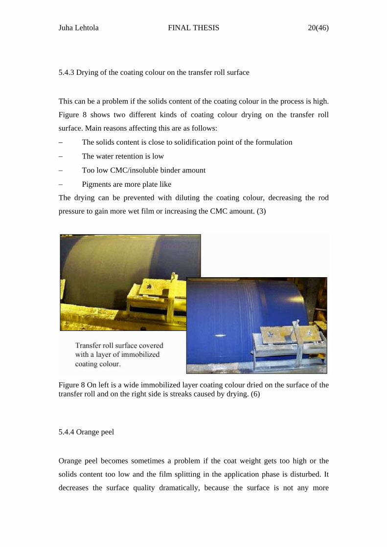
5.4.3 Drying of the coating colour on the transfer roll surface
This can be a problem if the solids content of the coating colour in the process is high.
Figure 8 shows two different kinds of coating colour drying on the transfer roll
surface. Main reasons affecting this are as follows:
− The solids content is close to solidification point of the formulation
− The water retention is low
− Too low CMC/insoluble binder amount
− Pigments are more plate like
The drying can be prevented with diluting the coating colour, decreasing the rod
pressure to gain more wet film or increasing the CMC amount. (3)
Figure 8 On left is a wide immobilized layer coating colour dried on the surface of the transfer roll and on the right side is streaks caused by drying. (6)
5.4.4 Orange peel
Orange peel becomes sometimes a problem if the coat weight gets too high or the
solids content too low and the film splitting in the application phase is disturbed. It
decreases the surface quality dramatically, because the surface is not any more

Juha Lehtola FINAL THESIS 21(46)
smooth but bumpy. Orange peel has become one of the limiting factors in the film
transfer processes, because the machine speed is one of the variables that cause it if
the speed gets too high (4). And the both sides simultaneously coating units are
especially vulnerable when the speeds are increased. In figure 9 there is the
operational area as a function of solids content, it shows how the orange peel is a
problem with the high coat weights and how it becomes more possible when the
solids content is decreased.
Figure 9 Orange peel is a problem with high coat weights and gets more usual if the solids content is decreasing. (6)
5.4.5 Web stealing
Web stealing means that the paper web is attached uncontrolled to bottom or top roll
when it exits the press nip. This can happen if there is high wet film amount after the
nip or the machine speed is too high. This makes the paper web alternate between the
top and the bottom rolls, which has an effect on the surface quality. Web stealing is
demonstrated in figure 10. The higher the speed or the bigger the amount of wet film
the longer the distance that the paper web follows the applicator rolls. (5) The web
stealing can appear either on the whole web width or just on the edges. It immediately
causes streaks or pattern in the coated surface. The streaks are usually 10-20 mm wide
or wider and oriented in the machine direction (3).

Juha Lehtola FINAL THESIS 22(46)
Figure 10 Web stealing after the press nip may become a problem with high speeds and big wet film amounts. (6)
5.5 Film coating usage
In the beginning the film transfer units were only used for surface sizing to replace
old pond size presses and that is still very usual. Nowadays film transfer processes are
also commonly used as a precoating unit for double or triple coated grades.
Sometimes they are used for final coating, but then rarely both sides at the same time
type of systems. It is very useful as a standard LWC offset grade coater, still there are
some problems with the rotogravure grades, because the lack of smoothness, but it
can be used with low grammages (4). The future seems quite bright with the film
coaters, because the lack of space in rebuilds, so very often the film coating unit is the
only possible solution. Growing usage of recycled fibres demands more and more
gentler coating processes and that is where film coaters are needed.
6. COATING COLOUR RAW MATERIALS
The target in Sittingbourne is to make a precoat for double coated wood free paper for
offset printing. The most important thing is to get the precoating attach tightly to the
base paper and afterwards to get the surface layer smoothly on the precoating layer. In

Juha Lehtola FINAL THESIS 23(46)
the Sittingbourne mill the coating colour is mixed in the coating preparation plant and
from there it is pumped to the coating unit’s feed tanks. The used raw materials are
calcium carbonate, latex, starch, NaOH, Optical brightener agent (OBA) and blue
pigment. Usually the shares of these raw materials is about 75-95 % of dry coat
weight is pigment (calcium carbonate) and the rest is mostly binders (lateces and
starch), leaving the share of additives (NaOH, OBA and blue pigment) to about 1 %
(4). Next is introduced the raw materials that were used in the Sittingbourne Paper
Mill.
6.1 Ground calcium carbonate (GCC)
The ground CaCO3 is a great pigment for precoating of WFC-papers. It is quite a
cheap pigment. The need of binders is low with the GCC, because of its shape, which
has a large characteristic area. In the precoating process GCC improves the attaching
of the surface layer, which is important for offset grades. Other reasons for using
calcium carbonate as pigment are as follows: (4)
− High brightness
− High whiteness
− Betters opacity and porosity
− Good printing ink absorption
− Less blistering in the offset printing
− GCC lowers viscosity
− Can be used in high solids contents
− Good OBA efficiency
6.2 Binders
The binders are used for binding pigment particles together and more importantly
attaching the pigments tightly to the paper web surface. Binders have also other
important properties that influence on the final coating colour mixture. Hoped
properties are for example high binding ability, colourless or high whiteness, good
water retention and good rheological properties. (4)

Juha Lehtola FINAL THESIS 24(46)
6.2.1 Latex
Latex is a synthetic polymer water mixture, so it is basically plastic particles in water
(4). Lateces have very high binding ability, good wet strength and low viscosity.
Latex gives the possibility to use high solids contents in the coating colour
formulations and they give the paper good calenerabilty and printability (10).
However the lateces can’t be used as the only binder, because they have so poor water
retention. So they must be used with for example starch or CMC. Lateces are also
very temperature- and pH dependent, also foaming and sensitivity for shear forces can
be a problem (4).
6.2.2 Starch
Starch is the most commonly used water-soluble binder. Starch can be produced from
potatoes, maize and wheat. It is not ready for use straight from these plants. The
structure chains have to be broken first to smaller pieces and some chemicals added to
these structures. Then it is ready for use with good solubility and viscosity properties.
Starch has alone poor binding ability and it is mainly used with latex and in these
mixtures it works to make higher viscosity and to enhance the water retention. When
starch is dried it forms a hard non-flexible surface. It is very cheap raw material and it
has good runnabilty properties. (4)
6.3 Additives
NaOH, OBA and blue pigment are used in the coating colour as additives. Each one
of them has a special function making the mixture work better. NaOH is used for
adjusting the pH of the coating colour to optimal and also to get certain surface pH
that is required by the printing process. OBA is used to get higher brightness, it works
by reflecting the UV-radiation back as bluish visible light to get the image that the

Juha Lehtola FINAL THESIS 25(46)
paper is actually brighter than it is (10). Blue pigment is used to get the feeling that
the paper is whiter than it is, because human eye sees bluish as whiter.
6.4 Measured properties from coating colour
There are some very important variables that are observed many times in one shift (12
hours). Viscosity, solids content, pH, and temperature are the four most observed
variables. They are all big factors in the rheological behaviour of the coating colour.
Values for these four are measured in a laboratory straight from fresh samples. In
some mills there are also on-line measurement units that can give estimations and
directions for the variables.
6.4.1 Solids content
Solids content has an effect on the dry coat weight so it is very important to keep
stable. The higher the solids content is the higher the coat weight is. In film transfer
coating it is important not to let the solids rise too high because high coat weights may
cause orange peeling in the paper surface. Too high solids content may also cause
increasing wearying in the machinery. It should be kept constant also because it has
an effect on viscosity, lower solids decrease viscosity. The coat weight can be
adjusted by changing the solids content from the coating preparation plant by putting
more or less water in the coating colour mix and the fine adjusting is made with the
rod pressure. Figure 11 shows how the solids content and the rod pressure change coat
weight. This is very accurate way to adjust it but quite slow, because it takes a couple
of hours to have an effect on coating colour circulation, where is tons of coating
colour circulating.

Juha Lehtola FINAL THESIS 26(46)
Figure 11 The effect of solids content and rod pressure on coat weight. (6)
6.4.2 Viscosity and temperature
Viscosity is the most important variable in the rheological behaviour of the coating
colour. Viscosity is strongly depended on temperature. So the process temperature
should be kept as constant as possible to reduce viscosity changes. This is important
both in the preparation plant and in the coating machinery. Coating colour viscosity
usually decreases when temperature increases. Viscosity is also very sensitive for
particle size, particle shape and particle size distribution changes. It decreases when
particle shape changes closer to spherical, because the non-regular shaped particles
have difficulties to arrange in order. If the particle size is decreased the viscosity will
increase, because the space between particles gets smaller in the same solids content.
When the particle size distribution is narrowed the viscosity will decrease, because
there are more similar size particles and they can move more freely together and by
each other. Air removal is also very important in the coating processes, because air
bubbles increase the viscosity strongly and they may also cause streaking. (4)
6.4.3 Water retention
Water retention indicates the coating colour’s ability to hold water in itself after
application. If the water retention is good, the solids content of the coating colour is
stable. If the solids content increases during coating, the water of the coating colour

Juha Lehtola FINAL THESIS 27(46)
penetrates into the paper, which can cause uneven binder distribution on coated paper.
Water retention has an effect on runnability in the coater. (3)
6.4.4 pH
The pH must be adjusted to prevent unwanted chemical reactions to happen and on
the other hand to get the wanted reactions to happen. The coating colour pH must be
adjusted on the level that is required by the printing process. Otherwise the printing
inks will not act as they are supposed to. Foaming is a common problem when the pH
gets too low and when calcium carbonate is used in coating colour. It is sensitive for
temperature variations so the measurements should be performed in accurate
conditions. (3)
7. REVIEW OF THE LITERATURE PART
M-real Sittingbourne Paper Mill has long history in papermaking. The first signs of
papermaking are as early as 1703 and the actual mill was founded in 1870’s. Since
that there has been 10 to 15 paper machines and nowadays there are two machines.
The mill itself has been strongly re-built in many process areas during recent years.
The main product in the mill is double-coated fine paper. This grade demands high
optical properties with over 90 % ISO standard brightness and whiteness. This is
achieved by using calcium carbonate as fillers and in the coating layers. The coating
layers are on-line film transfer coating as precoat and finally blade coating off
machine.
The on-line film coating requires from the base paper certain things including good
smoothness and very uniform cross and z-directional profiles. On the other hand, the
tear and tensile strengths don’t have to be extremely high, because there is no
doctoring element against the paper web. Surface strength still is very important for
both the base paper and the coating layers, because the products are printed mainly
with offset. Film coating method suites very well for the offset printing, because it has

Juha Lehtola FINAL THESIS 28(46)
excellent coating coverage. The lack of smoothness is a problem for rotogravure
printed grades.
The coating colour raw materials play a big role in coating. With ground calcium
carbonate can be achieved high brightness and whiteness and good attaching between
the two coating layers. Latex and starch are used together, because of their high
binding strength and good water retention together. Some optical brighteners and blue
pigments can be used to make the paper look whiter than it actually is. The coating
colour has some critical properties that are observed on-line and a couple of times in a
shift in laboratory, for example solids content, viscosity, temperature and pH.
EXPERIMENTAL PART
8. WORK BACKGROUND
After the investigations and assessing the situation in the PM15 and SymSizer it was
time to think about the trials. In the beginning of my research the CD profile
variations increased in the SymSizer so some development to that problem had to be
done also. Trials were planned carefully with my boss Simon Tyler, Senior Product
Development Engineer and with Production Manager and mill’s Technical Manager.
After planning I implemented the trials with the workers in different shifts.
9. TRIALS
For the original project plan concerning the MD variations I had some suggestions for
trials and those were first discussed with my boss and then accepted by mill
personnel. Two trials were made for the MD variation. First checking the on-line
measurement systems and their accuracy in showing the coating colour consumption
and the coat weight. Second was to test how coat weight changes when water is added
in the coating colour in the preparation plant. Same time with the second test was to
be tested how the CD spread value reacts to rod pressure changes. For the CD profile

Juha Lehtola FINAL THESIS 29(46)
problems the SymSizer roll and rod temperatures were measured and compared to
coat weight profiles in the third trial.
9.1 Coating colour consumption
First step for this trial was to measure how much the SymSizer consumes coating
colour by measuring the consumption from the preparation plant. Then compare it to
the value that the on-line system shows. This was to be made a couple of times to get
accurate results.
9.1.1 The trial
The preparation plant controller makes a mixture batch in a mixing tank, when it is
ready the colour is dropped in to the precoat machine tank. From there goes a pipeline
in to the SymSizer feed tank and back so there is a ring where the colour circulates.
There is an automatic valve in the pipeline that is controlled by level indicator of the
feed tank. So whenever the level drops to certain amount the valve opens and the tank
is filled again. To get the consumption all that is needed is to drop a certain sized
batch to the precoat machine tank and measure how long does it take for the SymSizer
to consume it. Then calculate the amount that is used in an hour and compare it to the
value that the on-line system shows. It had to be calculated from the average coat
weight from the same hour that the measurement was made.
9.1.2 Results
The measurements went well and three results were achieved on three days. All of
these results show that some improvement has to be done for the on-line measurement
equipment. In the first trial the operator dropped six tons of coating colour in to the
machine tank and it took 60 minutes to consume it. In table 1 are the results and
calculations of the trial. The solids content was measured before and after the drop
and an average was taken, but both of the values were the same, 68 %. Paper machine

Juha Lehtola FINAL THESIS 30(46)
speed during this trial was 781 m/min and the trim was 3.90 metres. In table 1 there
are three values highlighted they are the coat weight values. First there is the value
that is measured from the actual coating colour consumption, second is the Measurex
value that is seen in the operator room monitors on-line, the value is the average from
the 60 minutes time. Third value is from the QIS-system that is the mill’s surveillance
system, it measures the average values from Measurex for every reel that is made in
the mill and saves them in the database.
As seen from table 1 there is quite a big difference. Very problematic is that if the
target that the SymSizer operator is trying to reach is 20 g/m2 and the Measurex
shows just 19 g/m2 the operator tries to increase the coat weight. But the actual coat
weight has been already over 22 g/m2 so the result is that the quality is getting poorer
all the time. The last three lines in the tables 1.2 and 3 are calculations of how much
the mill would waste coating colour if the Measurex and QIS –values were correct. As
seen from table 1 there would be over 20 tons waste every 24 hours, so that would be
recognisable in the waste water department. So the on-line measurement values must
be incorrect. The same error is seen in the other two trials also that are shown in the
tables 2 and 3.
Table 1 The results of the first coating colour consumption measurement. 26.8.2005Machine speed m/min 781,00Web width m 3,90Kilos of coating colour 6000,00Time of consumption 60,00Solids content 0,68
Coating g/min 100000,00Dry coating 68300,00m2/min 3045,90Measured CWt /m2 22,42Measurex value 19,00QIS value 18,07kg/min wasted if true 10,43kg/24h wasted if true 15016,18kg of slurry wasted in 24h 21985,62
The process parameters are a little different in table 2, but it doesn’t matter because
the calculations still are correct and the results are the same. Again there is over four

Juha Lehtola FINAL THESIS 31(46)
grams difference in the coat weight value between the trial and the Measurex and
waste amount over 30 tons per day.
Table 2 Results from the second trial concerning the coating colour consumption. 30.8.2005Machine speed m/min 801,00Web width m 3,90Kilos of coating colour 7500,00Time of consumption 67,00Solids content 0,69
Coating g/min 111940,30Dry coating 77014,93m2/min 3123,90Measured CWt /m2 24,65Measurex value 20,00QIS value 18,96kg/min wasted if true 14,54kg/24h wasted if true 20933,17kg of slurry wasted in 24h 30426,12
Third trial was made to ensure that the results were correct. And again they show that
there are problems with the calibration of the Measurex system. In table 3 is seen that
still there is about four grams difference between the actual coat weight and the on-
line measurement system.
Table 3 Results from the third trial concerning the coating colour consumption. 31.8.2005Machine speed m/min 831,00Web width m 3,90Kilos of coating colour 7500,00Time of consumption 72,00Solids content 0,69
Coating g/min 104166,67Dry coating 71770,83m2/min 3240,90Measured CWt /m2 22,15Measurex value 18,50QIS value 18,41kg/min wasted if true 11,81kg/24h wasted if true 17012,42kg of slurry wasted in 24h 24691,47

Juha Lehtola FINAL THESIS 32(46)
9.1.3 Analysing the results
This trial shows clearly one problem concerning the MD variability. When the crews
in the shifts do not know the real coat weight that they are running it is impossible to
control the coat weight. According to this trial the coat weight is all the time much too
high and even worse the controllers are trying to increase it because they think that
they are too low on coat weight. In the literature part was explained how too high coat
weight may occur as serious quality problems and it could affect runnability problems
too. There were no real quality problems this time but runnability was a little poor.
There were quite much web breaks, which is unusual for the PM15, because normally
they run a couple of days without any break at all. Figure 12 shows a bit clearer the
problem. There can be seen the four grams difference in each trial between the actual
coat weight and the Measurex value. The incorrect QIS-value compared to the actual
coat weight is very challenging for the Research and Development people. They think
that the coat weight is low all the time and try to do work to increase it. Same thing is
for the people working on the quality, because the quality is probably something else
than they are predicting.
Measured CWt vs. Measurex vs. QIS
171819202122232425
1 2 3
Trials
Coat
wei
ght (
g/m
2)
Measured CWt /m2 Measurex value QIS value
Figure 12 The actual coat weight is four grams more than the Measurex is showing and the QIS is even lower.

Juha Lehtola FINAL THESIS 33(46)
9.2 Coating colour dilution in the preparation plant
This trial included two parts. In the first part water was added to the coating colour
mixture and then to the circulation ring. The purpose was to find out how long does it
take to have an effect on the solids content in the SymSizer coating colour circulation
and how long does it take to reach equilibrium in solids content and further how does
it change the coat weight. When adding water to the mixture the solids content should
decrease and with it the coat weight should drop too. After the part one begins
immediately the second part where the purpose is to increase the coat weight by
decreasing the rod loading gradually. When the rod loading is being decreased other
objective is to observe does it have an effect on the CD spread value. The CD spread
value gives the information how the rod pressure changes the CD profiles, basically it
is the standard deviation value of the CD coat weight variation.
9.2.1 The trial
The first part of the trial began with adding two parts of water in to the coating colour
mixture. The solids content was measured in the beginning of the trial. After an hour
the first solids content samples were taken from the SymSizer feed tank. Samples
were first taken every half an hour, but after two samples the decision was made to
take one every hour, because the change was so slow. After the solids content began
to reach equilibrium and the coat weight had dropped to a certain level started the part
two of this trial. The rod loading was decreased gradually after every reel change so it
was easy to get the average coat weight and CD spread results straight from the QIS-
system. And finally the rod loading was put to a level that was the target for the grade
that was running during trial.
9.2.2 Results
The first sample was taken at 10.40 o’clock from the original coating colour without
the added water. The solids content was 69.7 %. The first drop of the mix with two
parts of water was at 12.30, just before the drop the solids content was still 69.7 %.

Juha Lehtola FINAL THESIS 34(46)
The first sample with the two parts of water in the mixture was taken at 13.30 and the
last one at 17.00. I started to take samples twice in an hour. Between 12.30 and 13.00
the dilution had affected a little and it kept decreasing the solids content quite steadily
down to 14.00 o’clock when the solids content was 69.1 %. After that the value
started to reach equilibrium by dropping only about 0.5 % per hour so the samples
were decided to be taken once in an hour. By 17.00 o’clock the solids content had
dropped to 68.93 % and no more samples were taken. The results are in table 4.
During the time between 12.30 and 17.00 the coat weight dropped a little over 1 g/m2.
This follows very well the theory of film coating, because there is a rule of thump that
+/- 1 % solids content equals +/- 1 g/m2.
Table 4 The effect of two parts added water to the solids content and to the coat weight as a function of time.
Time Solids content CWt (g/m2)10,40 69,7012,30 69,70 19,513,00 69,6013,30 69,4514,00 69,1015,00 69,0516,00 69,0017,00 68,93 18,3
After the solids content had reached equilibrium began the part two from this trial.
When the part two began the rod loading was 2.5 bars in both application heads. And
the coat weight was 18.3 g/m2. The test was started by decreasing the rod loading to
2.2 bars and then observing how long does it take to increase the coat weight and
reach equilibrium. In table 5 is also the “time of change” column, which tells if the
coat weight change was rapid or slow. Slow means a few minutes and quick is less
than one minute. Changes carried on after every reel change down to 1.8 bars when
the coat weight had increased to 19.2 g/m2. This the maximum that could be changed,
because during this time the coat weight CD spread got quite poor and there were
quality limitations that had to be obeyed. In table 6 is shown how the CD spread
responded to the decreasing of the rod loading. As the pressure was decreased the CD
profile started to go worse from 1.81 to 2.26 and the mill personnel ordered the rod
loading to be increased. First the rod pressure was increased to 2.1 bars and the coat
weight dropped immediately to 17.8 g/m2 and the CD spread values lowered to 2.21.

Juha Lehtola FINAL THESIS 35(46)
Improvement was still needed and the rod pressure was put to 2.3 bars. After this the
coat weight changed to 17.5 g/m2 and the CD spread dropped to satisfied level of
1.72.
Table 5 The effect of rod loading on coat weight and the response time of the change. Reel number Rod Load (bar) CWt (g/m2) Time of change
5798 2,5 18,3 slow5799 2,2 18,5 slow5800 2 18,8 slow5801 1,8 19,2 slow5802 2,1 17,8 very quick5803 2,3 17,5 quick
Table 6 The effect of rod loading on the CD spread. Reel number Rod loading CD spread
5798 2,5 1,815799 2,2 1,915800 2 1,915801 1,8 2,265802 2,1 2,215803 2,3 1,72
9.2.3 Analysing the results
Part 1
The results from the first part of the trial were just as predicted. When the extra water
starts to affect the solids content decreases and so does the coat weight. The main
target on the other hand was to define how long does it take to have an effect on the
solids and how long to reach equilibrium. From figure 13 can be seen that it takes
about 1.5 hours to the water to really have an effect on solids content. During that
time the solids content had dropped from 69.70 % to 69.10 % and after that it took
three hours to decrease 0.20 % so clearly the solids content began to reach
equilibrium. In coat weight wise during the 1.5 hours the coat weight had dropped
about 0.6 g/m2, according to the rule of thump where 1 % change in solids means 1
g/m2 in coat weight. In table 4 was mentioned that during the whole trial the coat
weight had decreased from 19.5 g/m2 to18.3 g/m2 and at the same time the solids
content dropped about 1 %.

Juha Lehtola FINAL THESIS 36(46)
Effect of dilution on solids
68,80
69,00
69,20
69,40
69,60
69,80
10,40 12,30 13,00 13,30 14,00 15,00 16,00 17,00
Time
Sol
idss
con
tent
(%)
Solids content
Figure 13 The effect of dilution on solids content when two parts of water is added in the preparation plant.
For controlling the MD coat weight in the SymSizer the dilution in the preparation
plant is very accurate way of adjusting and it stays stable after the effect of the water.
The most important thing is to be patient. If the operator wants to change the coat
weight this way it can take over four hours to get the wanted change. During the trial
the preparation plant operator was told to put two parts of water to the mix at 10.40
am and the first drop to the circulation was 12.30 pm and after 2 pm the solids content
was still decreasing slowly. Still if the dilution is well planned and the two operators
have good connection the wanted solids decrease can be achieved in 2 hours. As
control strategy wise the two parts of added water changed the coat weight about 1
g/m2 and further trials should be made to investigate how different water amounts
change the coat weight. Now there was no time to test if the coat weight change is
linear as a function of dilution water amount, but now it is tested that it is as a
function of solids content.
Part 2
After the coat weight had decreased to 18.3 g/m2 began the part two of the trial where
the target was to test the effect of rod loading on coat weight and CD spread. In the
beginning the rod pressure was 2.5 bars and the changes were made every time the

Juha Lehtola FINAL THESIS 37(46)
reel was changed. The first change was to decrease the rod loading to 2.2 bars. The
coat weight increased to 18.5 g/m2 and it changed quite slowly as mentioned in table
5. Figure 14 shows how the rod loading changes the coat weight. The coat weight
follows almost linearly the rod pressure changes, but in the opposite way. During the
trial the rod pressure was changed gradually down to 1.8 bars and then the coat weight
had increased to 19.2 g/m2. At the same time the CD spread value had also changed
and it had gone so poor that the rod pressure couldn’t go any lower, because the paper
quality would have been too poor then. The CD spread changes are seen in figure 15.
The biggest change towards poor CD profile happened when the rod loading was
changed from 2.0 bars to 1.8 bars. That time the CD spread changed from 1.9 to 2.26.
After that the rod pressure was increased to 2.1 bars and finally put to 2.3 bars. This
improved the CD spread and as predicted the coat weight dropped. With the 2.3 bars
rod pressure was achieved quite good CD spread value as it dropped to 1.72, which
was better than in the beginning when the pressure was 2.5 bars. Weird thing about
the decreased coat weight was that it dropped lower than it had earlier been with
similar rod pressures. For example with 2.2 bars the coat weight was 18.5 g/m2 and
with the 2.3 bars it was 17.5 g/m2. This might indicate that the solids content was still
decreasing a little and affecting the difference between the values. As table 5 shows
the change in the coat weight was very quick when the rod pressure was increased
unlike when it was decreased.
The effect of rod loading on CWt
1,6
1,8
2
2,2
2,4
2,6
5798 5799 5800 5801 5802 5803
Reel Number
Rod
load
(bar
)
16,51717,51818,51919,5
Coa
t wei
ght
(g/m
2)
Rod Load (bar) CWt (g/m2)
Figure 14 The effect of rod loading on coat weight.

Juha Lehtola FINAL THESIS 38(46)
The effect of rod loading on CD spread
1,6
1,8
2
2,2
2,4
2,6
5798 5799 5800 5801 5802 5803
Reel Number
Rod
load
(bar
)
1,6
1,8
2
2,2
2,4
2,6
CD s
prea
d
Rod loading CD spread
Figure 15 The effect of rod loading on the coat weight CD spread.
This trial indicates clearly the risks of adjusting the coat weight too much with the rod
loading. First of all there can never be said beforehand what the coat weight is going
to be with certain rod loadings, because there more dominating process variables such
as the dilution water amount. Of course the MD coat weight fine tuning can be made
with rod pressure, but it has to be observed all the time how it reacts to changes. For
example if the coat weight is something with 2.0 bars rod pressure it can be
completely different in three hours if something else has changed in the process as
figure 14 shows. The other thing is the CD spread. The trial made it clear that the rod
pressure has an effect on the CD profile. Especially the change between 2.0 and 1.8
bars was significant as seen in figure 15. This indicates that changing the rod loadings
may cause quality problems if the CD profiles are not observed often enough. This
may have an effect on the final product also if the top coating layer is not attaching
the precoating uniformly, it may cause problems in the printing process.
9.3 Temperature profiles at the coating station
This trial was done to find out if the application rolls and the metering rods
temperatures had any influence on the coat weight CD profiles. The temperatures
were measured with an infrared hand thermometer from several spots along the rolls
and rods then figures were drawn and compared with the QIS-system coat weight

Juha Lehtola FINAL THESIS 39(46)
profiles. The temperature profile is important for the product for two main reasons.
First the machinery alignment is strongly depended on the temperatures in the station.
Second one is the moisture profile at the coating unit changes if the temperatures are
considerably different between front and backside.
9.3.1 The trial
The trial was carried through in three days. During that time I made three temperature
figures and compared them to QIS coat weight profiles. In the first measurement there
were seven spots from the rolls and rods measured with the temperature measurement
device. In the second and third ones I wanted to get more accurate results and took 16
spots and drew the figures from them. The first and the second test showed that the
problem was in the bottom roll and rod so from the third test there is a figure only
from them and not from the top ones.
9.3.2 Results
During the trial the top roll and rod temperatures did not have considerable variation,
as seen in the figures 16 and 19. The rod temperature was lower than the roll’s in the
top rod, but in the bottom the rod and the roll temperatures were quite similar. After
two measurements the top temperatures were left, because they didn’t have the
variation that the bottom ones did. The figures 17 and 18 indicate the correlation
between the coat weight and the temperature. The coat weight profile clearly follows
reversed the temperature profile. On the next day the test was repeated and the figures
20 and 21 show how the profiles are still very similar. During that day the results
were shown to mill personnel and they tried to make corrections to the profiles by
changing the cooling water flows at the SymSizer bottom application roll. Figure 22
shows how the roll temperature has levelled to around 51 oC and the coat weight
profile has got a bit better. Still there is a two degrees temperature difference between
the front and backside and that is seen in figure 23 where the coat weight profile is
also a little higher in the front edge than the back edge.

Juha Lehtola FINAL THESIS 40(46)
Top Roll and head temperatures
3839404142434445
Fron
t
Back
Tem
pera
ture
(C)
Roll Rod
Figure 16 Temperature profiles of the top roll and rod in the first test.
Btm roll and head temperatures
44464850525456
Fron
t
Back
Tem
pera
ture
(C)
Roll Rod
Figure 17 Temperature profiles of the bottom roll and rod in the first test.
CWt profile, reel 5917
17,00
18,00
19,00
20,00
21,00
22,00
23,00
Fron
t
Back
Coa
t wei
ght (
g/m
2)
Figure 18 Coat weight profile during the first test.

Juha Lehtola FINAL THESIS 41(46)
Top roll and rod bed temperatures
3537394143454749
Fron
t
Back
Tem
pera
ture
s (C
)Roll Rod
Figure 19 Temperature profiles of the top roll and rod in the second test.
Btm roll and rod bed temperatures
47484950515253
Fron
t
Back
Tem
pera
ture
(C)
Roll Rod
Figure 20 Temperature profiles of the bottom roll and rod in the second test.
CWt profile, reel 5944
17,0017,5018,0018,5019,0019,5020,0020,5021,0021,5022,00
Fron
t
Back
Coa
t wei
ght (
g/m
2)
Figure 21 Coat weight profile during the second test.

Juha Lehtola FINAL THESIS 42(46)
Btm roll and rod bed temperatures
44464850525456
Fron
t
Back
Tem
pera
ture
(C)
Roll Rod
Figure 22 Temperature profiles of the bottom roll and rod in the third test.
CWt profile, reel 5969
15,0015,5016,0016,5017,0017,5018,0018,5019,0019,5020,00
Fron
t
Back
Coa
t wei
ght (
g/m
2)
Figure 23 Coat weight profile during the third test.
9.3.3 Analysing the results
All three measurements show clearly what is the influence of temperature on the coat
weight profile. The last test where the application roll cooling water flows had been
adjusted shows that the roll temperatures are extremely important for the coat weight.
The reason is that the coating colour dries faster on the surface of the applicator roll in
the areas where it is hotter. The drier the coating colour is the less is attaching the
paper web and more is sticking on the applicator roll surface. The temperature

Juha Lehtola FINAL THESIS 43(46)
difference between the top and bottom can be explained with the lack of ventilation
between the hot paper web and the SymSizer unit. That is why there is so much hotter
than on the top roll, which is located freely in the machine hall air and is well
ventilated.
There might be problems with the water circulation temperatures, because there are
no heat exchangers to control the cooling waters for the application rolls and also for
the application heads. The cooling is adjusted manually from the water feed tanks
with putting more or less fresh water in there. This affects easily heavy fluctuation in
the temperatures in the rolls and heads. A heat exchanger that could keep the waters in
stable temperature would help the operators a lot and also decrease the CD variation.
10. CONCLUSION OF THE TRIAL RESULTS
These trials were run to decrease the machine direction coat weight variation and at
the same time to observe how does the adjustments change the cross directional coat
weight profiles. Some results were achieved that improved the process.
In the first trial the on-line measurement systems were checked and some problems
were found. The coat weight was all the time about 4 g/m2 higher than what it actually
was according to the real coating colour consumption. This caused problems in
adjusting the coat weight to targets and it may have caused some runnability issues.
The high coat weight didn’t have an effect on quality yet, but certainly it is going out
of the operation window of the SymSizer if the coat weight is still increased. After the
Measurex-system calibration the problem should be solved.
The second trial gave the mill personnel information about the time that it takes to get
an effect on the coating colour circulation’s solids content after adding water at the
preparation plant. The results show that it took about two hours to reach equilibrium
in the solids content and in the coat weight. During this time the two parts of added
water decreased the solids content about 0.6 % and the coat weight had also decreased
among the solids about half a g/m2. It is quite a long time, but it is very effective and
accurate. The important thing is to be patient and wait for the solids to drop to a stable

Juha Lehtola FINAL THESIS 44(46)
condition before adjusting anything else such as rod loading. This trial continued after
the dilution by changing the rod loading and observing its effect on the MD coat
weight and CD spread. The MD coat weight acted just as predicted it increased when
rod pressure was lowered and decreased when rod pressure was increased. The CD
spread changed also quite linearly with the rod pressure by getting worse when rod
loading was decreased and the other way around when putting more pressure on the
rods. This indicated that when changing the rod loading during runs, the CD spread
values should be observed regularly until it starts to be stable. And if the process is
wanted to keep equilibrium the best way to change the coat weight is to add water in
to the coating colour mix at the preparation plant.
The third trial was about the poor CD profiles and how they correlate with the
SymSizer roll and rod temperature profiles. A straight correlation between these two
was found and the explanation is quite simple. The hotter areas on the applicator roll
surface dry the coating colour film more before the press nip so there is less coating
attaching the paper web. In the measurements the bottom rod’s temperature profile
was poor also, the applicator roll temperature most probably caused that. Solving the
problem began with adjusting the cooling waters in the bottom applicator roll and the
profile started to get better and the rod profile followed also. This trial shows clearly
that the cooling water temperatures inside the applicator rolls have to be kept constant
to keep the CD profiles acceptable.
11. SUGGESTIONS FOR IMPROVING THE PROCESS
The difference between the actual coating colour consumption and the on-line
measurement equipment values should be taken seriously. The calibration of the
devices should be observed more often and if needed to arrange similar trial that the
trial one in this thesis work was. If these problems keep occurring the manufacturer
must be contacted and improvement has to be done. The SymSizer is controlled based
on these on-line measurement details and if they are so incorrect that they were the
operator has an impossible task to keep the coat weight in targets and the quality may
get poorer and runnability gets worse.

Juha Lehtola FINAL THESIS 45(46)
Temperature control in the coating process especially in the film transfer method is
extremely important. A heat exchanger to control the cooling water temperatures
would be a great investment. Now when the waters are controlled manually they
fluctuate all the time. When operator wants to cool down the applicator rolls he
manually puts more fresh water in to the supply tanks and waits for the rolls to cool.
After cooling them enough the water is taken off, because the rolls would go to cool if
not. Now the temperature starts to rise again and begins a vicious circle. A heat
exchanger and automatic thermal indicators and controls would easily keep the
temperature stable and by that keep the coating profile even.
It would be advantageous if the operators could see how much coating colour is going
to either side of the paper. A system that measures both sides’ coat weights separately
would help to keep the paper’s surfaces uniform. This is needed because the forming
section is a Foudrinier type of wire section.

Juha Lehtola FINAL THESIS 46(46)
SOURCES
1. REED, MATTHEW. Sittingbourne coming into flower. Make it, a magazine
for M-real people, 2005, number 3, p. 12-15.
2. RALPH, STEVE. E-learning & Internal Communications Officer, M-real UK
Paper Mills, 2005.
3. Fapet Oy. Pigment coating and surface sizing. Jyväskylä, Gummerus Printing,
2000, ISBN 952-5216-11-X.
4. HÄGGBLOM-AHNGER, ULLA. Paperin ja kartongin valmistus. Jyväskylä,
Gummerus Kirjapaino Oy, 2001, ISBN 952-13-1280-7.
5. TURTIAINEN, TOMI. Pastan ja pohjapaperin vaikutus
filminsiirtotekniikkaan perustuvan päällystimen ajettavuuteen ja laatuun.
Tampere, 2001.
6. AARNIKOIVU, PIRKKO-LEENA. Training material for operators of
filmcoating with smooth rods. Metso Paper Inc., 2003.
7. RANTA, JUSSI. Coating concepts. Excursion material, Metso Paper
Järvenpää, 9.11.2005.
8. HAVUKAINEN, ROBERT. Drying of coated paper. Excursion material,
Metso Paper Järvenpää, 9.11.2005.
9. HÄGGBLOM-AHNGER, ULLA. Coating technology. Teaching material,
Tampere University of Applied Sciences, 2005.
10. SUOMEN PAPERI-INSINÖÖRIEN YHDISTYS. Paperin valmistus III, osa
1. Turku, Oy Turun Sanomat/Serioffset, 1983, ISBN 951-99479-0-6.