Embed Size (px)
Citation preview

TAMILNADU TRADE PROMOTION
ORGANISATION
Tender Document for the replacement of
Screw Chillers at Exhibition Hall No.1 & 2
TAMILNADU TRADE PROMOTION ORGANISATION
(A Joint Venture of Govt. of India and Govt. of Tamil Nadu)
Chennai Trade Centre Complex
Mount Poonamallee Road, Nandambakkam, Chennai – 600 089.
Phone No: 044-65480174, Fax No: 044-2231 3555
Website: www.chennaitradecentre.org
Email: [email protected]
DISCLAIMER
The information contained in this tender document or subsequently provided to bidders,
whether verbally or in documentary form by or on behalf of Tamilnadu Trade Promotion
Organisation (TNTPO) or any of their employees or advisors (collectively referred to as
“TNTPO representatives”), is provided to the bidders on the terms and conditions set out in this
document and any other terms and conditions subject to which such information is provided.
This document is not an agreement and is not a offer or invitation by TNTPO Representatives to
any other party. The purpose of this document is to provide interested parties with information to
assist the formulation of the proposal.
This document does not purport to contain all the information each bidder may require.
Certain bidders may have a better knowledge of the proposed assignment and than others. Each
bidder should conduct its own due diligence, investigations and analysis and should check the
accuracy, reliability and completeness of the information in this document and obtain
independent advice from appropriate sources. TNTPO Representatives make no representation of
warranty and shall incur no liability under any law, statue, rules or regulations as to the accuracy,
reliability of completeness of the document, the award of the assignment, the information and
any other information supplied by of on behalf of TNTPO or otherwise arising in anyway from
the selection process.
The prospective bidder will be responsible for all obligations to its staff, their payments,
complying with the labour laws, minimum wages Act and any other Act relevant for the working
of the bidder’s staff. Under no circumstances, TNTPO will be responsible for any non-
compliance with statutory requirements of the bidder’s staff.
TNTPO may in their absolute discretion, but without being under any obligation to do so,
update, amend or supplement the information in this document from time-to-time, after
intimating the same to the bidders. TNTPO reserves the right to accept or reject any or all
proposals without giving any reasons. The bidding process shall be governed by the laws of India
and courts at the State of Tamilnadu will have jurisdiction over the matter concerning and arising
out of document.
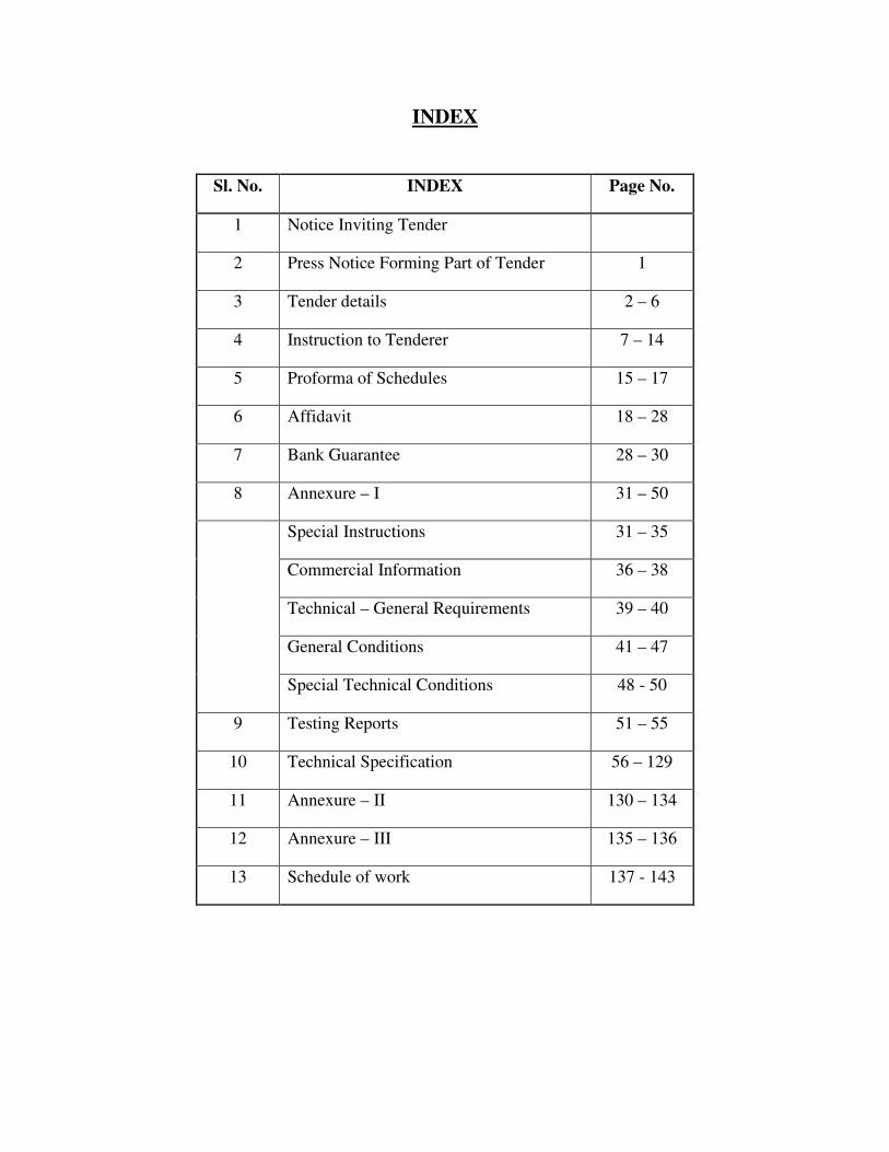
INDEX
Sl. No. INDEX Page No.
1 Notice Inviting Tender
2 Press Notice Forming Part of Tender 1
3 Tender details 2 – 6
4 Instruction to Tenderer 7 – 14
5 Proforma of Schedules 15 – 17
6 Affidavit 18 – 28
7 Bank Guarantee 28 – 30
8 Annexure – I 31 – 50
Special Instructions 31 – 35
Commercial Information 36 – 38
Technical – General Requirements 39 – 40
General Conditions 41 – 47
Special Technical Conditions 48 - 50
9 Testing Reports 51 – 55
10 Technical Specification 56 – 129
11 Annexure – II 130 – 134
12 Annexure – III 135 – 136
13 Schedule of work 137 - 143
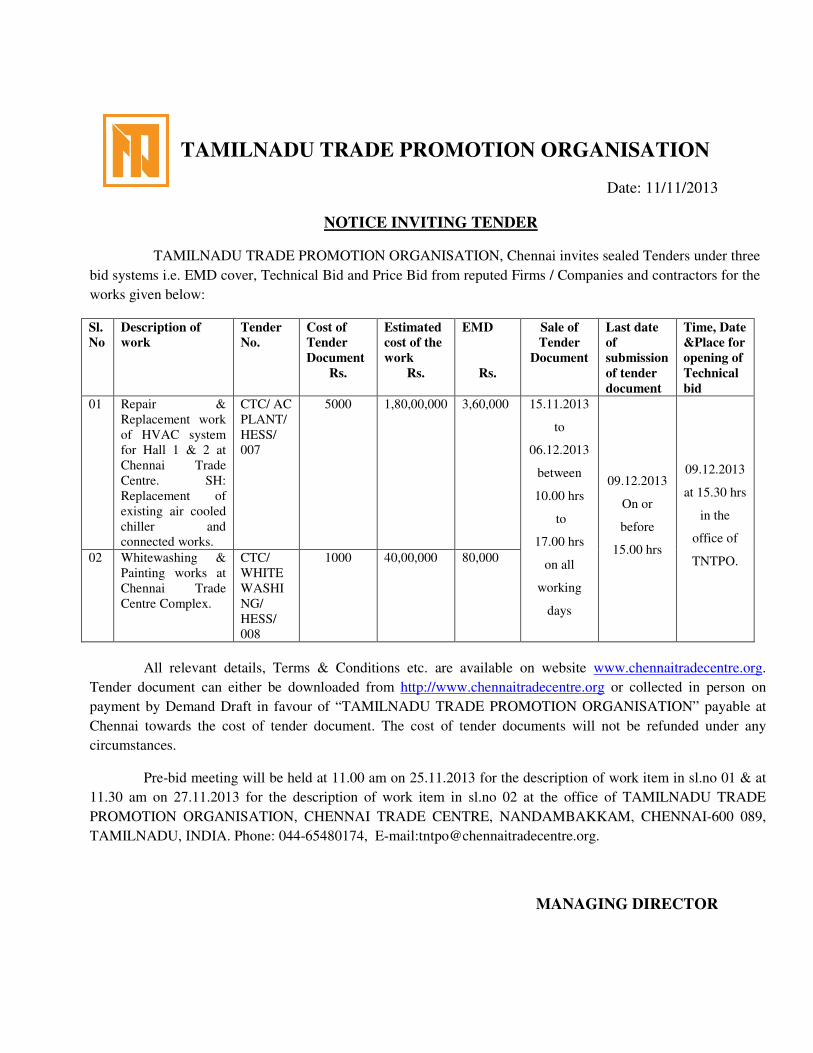
TAMILNADU TRADE PROMOTION ORGANISATION
Date: 11/11/2013
NOTICE INVITING TENDER
TAMILNADU TRADE PROMOTION ORGANISATION, Chennai invites sealed Tenders under three
bid systems i.e. EMD cover, Technical Bid and Price Bid from reputed Firms / Companies and contractors for the
works given below:
Sl.
No
Description of
work
Tender
No.
Cost of
Tender
Document
Rs.
Estimated
cost of the
work
Rs.
EMD
Rs.
Sale of
Tender
Document
Last date
of
submission
of tender
document
Time, Date
&Place for
opening of
Technical
bid
01 Repair &
Replacement work
of HVAC system
for Hall 1 & 2 at
Chennai Trade
Centre. SH:
Replacement of
existing air cooled
chiller and
connected works.
CTC/ AC
PLANT/
HESS/
007
5000 1,80,00,000 3,60,000 15.11.2013
to
06.12.2013
between
10.00 hrs
to
17.00 hrs
on all
working
days
09.12.2013
On or
before
15.00 hrs
09.12.2013
at 15.30 hrs
in the
office of
TNTPO. 02 Whitewashing &
Painting works at
Chennai Trade
Centre Complex.
CTC/
WHITE
WASHI
NG/
HESS/
008
1000 40,00,000 80,000
All relevant details, Terms & Conditions etc. are available on website www.chennaitradecentre.org.
Tender document can either be downloaded from http://www.chennaitradecentre.org or collected in person on
payment by Demand Draft in favour of “TAMILNADU TRADE PROMOTION ORGANISATION” payable at
Chennai towards the cost of tender document. The cost of tender documents will not be refunded under any
circumstances.
Pre-bid meeting will be held at 11.00 am on 25.11.2013 for the description of work item in sl.no 01 & at
11.30 am on 27.11.2013 for the description of work item in sl.no 02 at the office of TAMILNADU TRADE
PROMOTION ORGANISATION, CHENNAI TRADE CENTRE, NANDAMBAKKAM, CHENNAI-600 089,
TAMILNADU, INDIA. Phone: 044-65480174, E-mail:[email protected].
MANAGING DIRECTOR
1
TAMILNADU TRADE PROMOTION ORGANISATION
O/o The Managing Director,
Chennai Trade centre,
Poonamalle Road, Nandambakkam,
Chennai.
Tender No: CTC/AC PLANT/HESS/007 Dated:15.11.2013
PRESS NOTICE FORMING PART OF TENDER
The Managing Director, Chennai Trade Centre, Nandambakkam,
Chennai invites sealed item rate tender in three bid system from the
eligible companies or its authorized dealers and contractors from
the HVAC category specialized in similar HVAC works with
approved chiller makes of TRANE / CARRIER / DHUNHAMBUSH /
HITACHI / KIRLOSKAR / BLUESTAR / CLIMA VENETA / BLUE
BOX / DAIKIN / YORK / VOLTAS for the following work
2
TENDER DETAILS
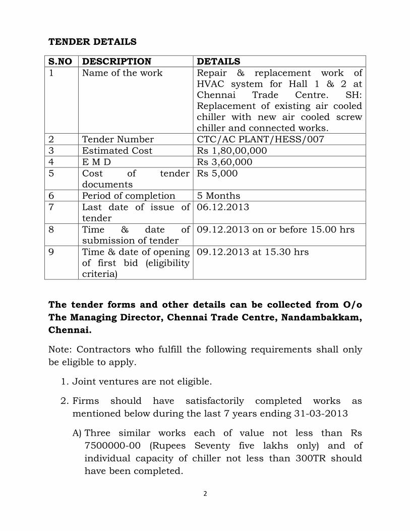
S.NO DESCRIPTION DETAILS
1 Name of the work Repair & replacement work of HVAC system for Hall 1 & 2 at Chennai Trade Centre. SH: Replacement of existing air cooled chiller with new air cooled screw chiller and connected works.
2 Tender Number CTC/AC PLANT/HESS/007
3 Estimated Cost Rs 1,80,00,000
4 E M D Rs 3,60,000
5 Cost of tender documents
Rs 5,000
6 Period of completion 5 Months
7 Last date of issue of tender
06.12.2013
8 Time & date of submission of tender
09.12.2013 on or before 15.00 hrs
9 Time & date of opening of first bid (eligibility criteria)
09.12.2013 at 15.30 hrs
The tender forms and other details can be collected from O/o
The Managing Director, Chennai Trade Centre, Nandambakkam,
Chennai.
Note: Contractors who fulfill the following requirements shall only
be eligible to apply.
1. Joint ventures are not eligible.
2. Firms should have satisfactorily completed works as
mentioned below during the last 7 years ending 31-03-2013
A) Three similar works each of value not less than Rs
7500000-00 (Rupees Seventy five lakhs only) and of
individual capacity of chiller not less than 300TR should
have been completed.
3
(OR)
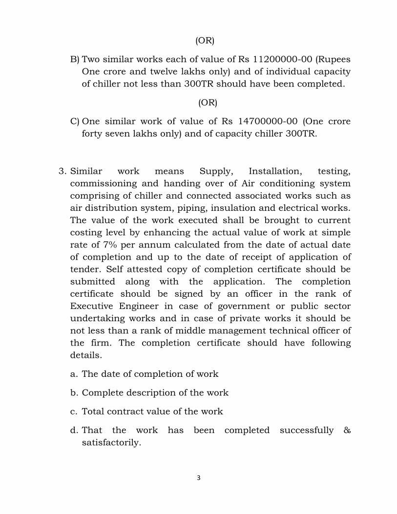
B) Two similar works each of value of Rs 11200000-00 (Rupees
One crore and twelve lakhs only) and of individual capacity
of chiller not less than 300TR should have been completed.
(OR)
C) One similar work of value of Rs 14700000-00 (One crore
forty seven lakhs only) and of capacity chiller 300TR.
3. Similar work means Supply, Installation, testing,
commissioning and handing over of Air conditioning system
comprising of chiller and connected associated works such as
air distribution system, piping, insulation and electrical works.
The value of the work executed shall be brought to current
costing level by enhancing the actual value of work at simple
rate of 7% per annum calculated from the date of actual date
of completion and up to the date of receipt of application of
tender. Self attested copy of completion certificate should be
submitted along with the application. The completion
certificate should be signed by an officer in the rank of
Executive Engineer in case of government or public sector
undertaking works and in case of private works it should be
not less than a rank of middle management technical officer of
the firm. The completion certificate should have following
details.
a. The date of completion of work
b. Complete description of the work
c. Total contract value of the work
d. That the work has been completed successfully &
satisfactorily.
4
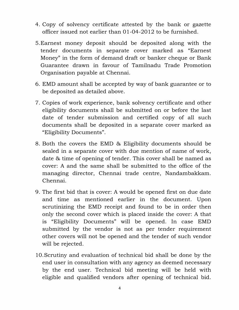
4. Copy of solvency certificate attested by the bank or gazette
officer issued not earlier than 01-04-2012 to be furnished.
5. Earnest money deposit should be deposited along with the
tender documents in separate cover marked as “Earnest
Money” in the form of demand draft or banker cheque or Bank
Guarantee drawn in favour of Tamilnadu Trade Promotion
Organisation payable at Chennai.
6. EMD amount shall be accepted by way of bank guarantee or to
be deposited as detailed above.
7. Copies of work experience, bank solvency certificate and other
eligibility documents shall be submitted on or before the last
date of tender submission and certified copy of all such
documents shall be deposited in a separate cover marked as
“Eligibility Documents”.
8. Both the covers the EMD & Eligibility documents should be
sealed in a separate cover with due mention of name of work,
date & time of opening of tender. This cover shall be named as
cover: A and the same shall be submitted to the office of the
managing director, Chennai trade centre, Nandambakkam.
Chennai.
9. The first bid that is cover: A would be opened first on due date
and time as mentioned earlier in the document. Upon
scrutinizing the EMD receipt and found to be in order then
only the second cover which is placed inside the cover: A that
is “Eligibility Documents” will be opened. In case EMD
submitted by the vendor is not as per tender requirement
other covers will not be opened and the tender of such vendor
will be rejected.
10. Scrutiny and evaluation of technical bid shall be done by the
end user in consultation with any agency as deemed necessary
by the end user. Technical bid meeting will be held with
eligible and qualified vendors after opening of technical bid.
5
The end user reserves the right to modify the technical &
commercial conditions/ specifications if required.
11. The time and date for opening of financial bid of vendors who
satisfy the eligibility criteria and whose technical bid is
accepted would be communicated to them at a later date.
12. When the bids are invited in three stages and if it is desired
to submit revised financial bid then it shall be mandatory to
submit such revised financial bid. If not submitted then the
financial bid submitted earlier will become invalid
automatically.
13. The end user Chennai Trade center reserves the right to
reject any prospective application without assigning any
reason and to restrict the list of qualified vendors to any
number deemed suitable by them, if too many bids are
received satisfying the laid down criteria.
14. Canvassing in any form is not accepted and Chennai trade
center reserves the right to reject issue of application form, to
those indulge in such act.
Managing Director
Chennai Trade Centre,
Nandambakkam, Chennai.
LIST OF DOCUMENTS TO BE SUBMITTED WITHIN THE
PERIOD OF TENDER SUBMISSION:
A. Eligibility Documents:
1. Certificate of work experience
2. Bank solvency certificate
3. Earnest deposit amount as specified.

6
A. Technical Bid Documents:
1. Schedule of technical specification and commercial
condition as per Annexure-I
2. Schedule of technical data as per Annexure-II
3. Schedule of addresses of manufacturer premises / places
of inspection as per Annexure-III
4. List of approved make as per Annexure-IV
5. List of technical literature & catalogue and any other
related technical information as per Annexure-V
6. Technical data sheet duly filled I all respect.
Note: All the above documents to be signed and seal to be
affixed.
B. Financial bid documents:
1. Schedule of work- Schedule A
Managing Director,
Chennai Trade Centre,
Nandambakkam, Chennai.
TAMILNADU TRADE PROMOTION ORGANISATION
O/o The Managing Director,
Chennai Trade centre,
Poonamalle Road, Nandambakkam,
Chennai.
7
Tender No: CTC/ACPLANT/HESS/007
Dated:15-11-2013
TAMILNADU TRADE PROMOTION ORGANIZATION
Office of The Managing Director, Chennai Trade Centre,
Nandambakkam, Chennai
INSTRUCTION TO TENDERERS
1 Item rate bids are invited eligible contractors in HVAC category and firms which are specialized in Similar HVAC Works for the work of “Repair & replacement work in HVAC System for Hall 1 & 2 at Chennai Trade Centre. SH: Replacement of existing air cooled chiller with new air
cooled screw chiller & connected works.
1.1. The work is estimated to cost Rs.1,80,00,000/. This estimate
however given is merely as a rough guide.
1.1.1. The authority competent to approve specification etc for the
combined cost and belonging to the major discipline will consolidate
details for calling the Bids. He will also nominate appropriate
agency which will deal with all matters relating to the invitation of
bids.
For composite bid, besides indicating the combined estimated cost
put to bid, Should clearly indicates the estimated cost of each
component separately. The eligibility of bidder will correspond to
the combined estimated cost of different components put to bid.
1.2. Intending tenderer is eligible to submit the bid provided he
has definite proof from the appropriate authority, which shall be to
the satisfaction of the competent authority, of having satisfactorily
completed similar works of magnitude specified below:-
8
Criteria of eligibility for submission of bid documents:
1.2.1. Conditions for all contractors:
As indicated in the `Press Notice` vide page – 1 & 2
1.2.2. To become eligible for issue of bid, the bidder shall have to
furnish an affidavit as under:
I/We undertake and confirm that eligible similar works(s) has/have
not been got executed through another contractor on back to back
basis. Further that, if such a violation comes to the notice of
Department, then I/we shall be debarred for biding in Chennai
Trade Centre in future forever. Also, if such a violation comes to
the notice of Department before date of start of work, the Engineer-
in-charge shall be free to forfeit the entire amount of Earnest Money
Deposit/ Performance Guarantee.
2. Agreement shall be drawn with the successful bidder on
prescribed Form or other Standard Form which is available as a
Govt. of India Publication. Bidder shall quote his/her rates as per
various terms and conditions of the said form which will Form part
of the agreement.
3. The time allowed for carrying out of the work will be 5
months from the date of start as defined in schedule `F` or from the
first date of acceptance of order, whichever is later, in accordance
with the phasing, if any, indicated in the bid documents.
4. The site for the work will be made available as and when it is
requested subject to the availability of existing chiller shutdown. In
any case centre business should not get affected and due care shall
be taken by the vendor while executing the work. Failure on part of
the vendor shall attract penalty equal to the double the value of loss
occurred by the centre.
5. The bid document consisting specifications, the schedule of
quantities of various types of items to be executed and the set of
terms and conditions of the contract to be complied with and other
9
necessary documents except Standard General Conditions of
Contract Form can be seen in the office of the Chennai Trade
Centre, Nandambakkam, Chennai.
6. When bids are invited in three stage system and if it is desire
to submit revised financial bid then it shall be mandatory to submit
revised financial bid. If not submitted, then the tender submitted
earlier shall become invalid.
7. Earnest Money in the form of Demand Draft or Banker`s
Cheque shall be deposited in original in office of The Managing
Director.
(i) Interested contractor who wish to participate in the bid
has also to make a payment of Rs.5000/- in the form of Cash or
Demand Draft/Pay order or Banker`s Cheque of any Schedules
Bank drawn in favour of The Managing Director, Chennai Trade
Centre, Chennai.
Demand Draft or Banker`s Cheque or Bank Guarantee against
EMD shall be placed in single sealed envelope superscribed with
name of work and due date of opening of the bid also mentioned
thereon.
Copy of certificate of work experience, Bank solvency certificate and
other eligibility documents shall be submitted with in the period of
tender submission and certified copy of each shall be deposited in a
separate envelope marked as “Eligibility Documents”.
Both the envelopes shall be placed in another envelope with due
mention of Name of work, date & time of opening of bids and to be
submitted in the office of The Managing Director after last date &
time of submission of bid up to 03:00 PM on 09.12.2013.
The documents submitted shall be opened at 03:30 PM on the
same day.
The bid documents submitted by intending bidders shall be opened
only of those bidders, whose Earnest Money Deposit, and other
10
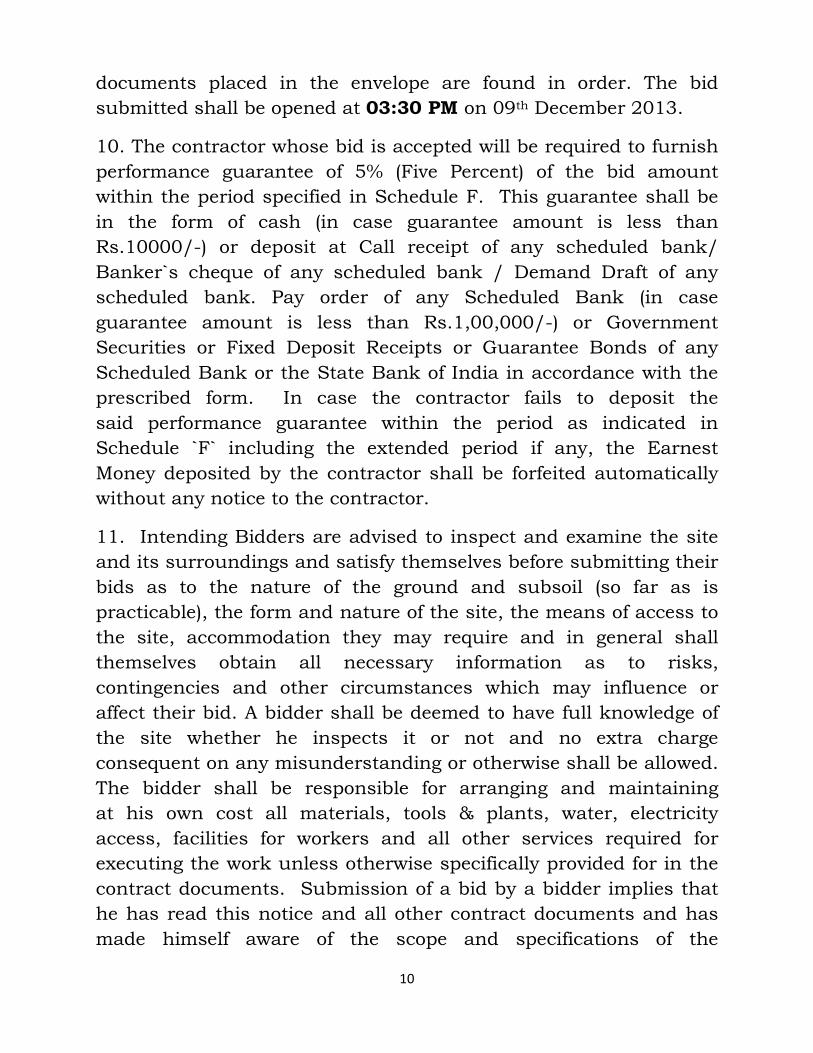
documents placed in the envelope are found in order. The bid
submitted shall be opened at 03:30 PM on 09th December 2013.
10. The contractor whose bid is accepted will be required to furnish
performance guarantee of 5% (Five Percent) of the bid amount
within the period specified in Schedule F. This guarantee shall be
in the form of cash (in case guarantee amount is less than
Rs.10000/-) or deposit at Call receipt of any scheduled bank/
Banker`s cheque of any scheduled bank / Demand Draft of any
scheduled bank. Pay order of any Scheduled Bank (in case
guarantee amount is less than Rs.1,00,000/-) or Government
Securities or Fixed Deposit Receipts or Guarantee Bonds of any
Scheduled Bank or the State Bank of India in accordance with the
prescribed form. In case the contractor fails to deposit the
said performance guarantee within the period as indicated in
Schedule `F` including the extended period if any, the Earnest
Money deposited by the contractor shall be forfeited automatically
without any notice to the contractor.
11. Intending Bidders are advised to inspect and examine the site
and its surroundings and satisfy themselves before submitting their
bids as to the nature of the ground and subsoil (so far as is
practicable), the form and nature of the site, the means of access to
the site, accommodation they may require and in general shall
themselves obtain all necessary information as to risks,
contingencies and other circumstances which may influence or
affect their bid. A bidder shall be deemed to have full knowledge of
the site whether he inspects it or not and no extra charge
consequent on any misunderstanding or otherwise shall be allowed.
The bidder shall be responsible for arranging and maintaining
at his own cost all materials, tools & plants, water, electricity
access, facilities for workers and all other services required for
executing the work unless otherwise specifically provided for in the
contract documents. Submission of a bid by a bidder implies that
he has read this notice and all other contract documents and has
made himself aware of the scope and specifications of the
11
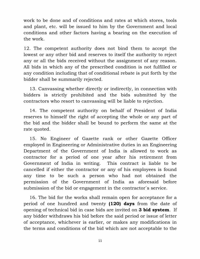
work to be done and of conditions and rates at which stores, tools
and plant, etc. will be issued to him by the Government and local
conditions and other factors having a bearing on the execution of
the work.
12. The competent authority does not bind them to accept the
lowest or any other bid and reserves to itself the authority to reject
any or all the bids received without the assignment of any reason.
All bids in which any of the prescribed condition is not fulfilled or
any condition including that of conditional rebate is put forth by the
bidder shall be summarily rejected.
13. Canvassing whether directly or indirectly, in connection with
bidders is strictly prohibited and the bids submitted by the
contractors who resort to canvassing will be liable to rejection.
14. The competent authority on behalf of President of India
reserves to himself the right of accepting the whole or any part of
the bid and the bidder shall be bound to perform the same at the
rate quoted.
15. No Engineer of Gazette rank or other Gazette Officer
employed in Engineering or Administrative duties in an Engineering
Department of the Government of India is allowed to work as
contractor for a period of one year after his retirement from
Government of India in writing. This contract is liable to be
cancelled if either the contractor or any of his employees is found
any time to be such a person who had not obtained the
permission of the Government of India as aforesaid before
submission of the bid or engagement in the contractor`s service.
16. The bid for the works shall remain open for acceptance for a
period of one hundred and twenty (120) days from the date of
opening of technical bid in case bids are invited on 3 bid system. If
any bidder withdraws his bid before the said period or issue of letter
of acceptance, whichever is earlier, or makes any modifications in
the terms and conditions of the bid which are not acceptable to the
12
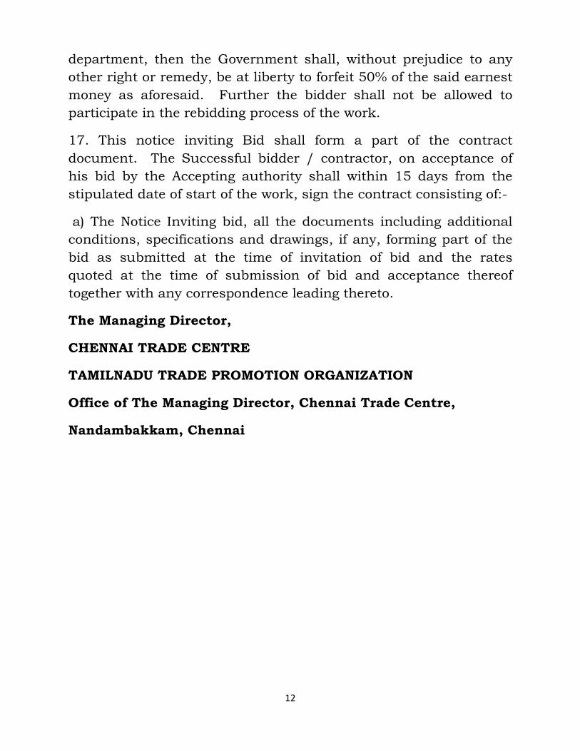
department, then the Government shall, without prejudice to any
other right or remedy, be at liberty to forfeit 50% of the said earnest
money as aforesaid. Further the bidder shall not be allowed to
participate in the rebidding process of the work.
17. This notice inviting Bid shall form a part of the contract
document. The Successful bidder / contractor, on acceptance of
his bid by the Accepting authority shall within 15 days from the
stipulated date of start of the work, sign the contract consisting of:-
a) The Notice Inviting bid, all the documents including additional
conditions, specifications and drawings, if any, forming part of the
bid as submitted at the time of invitation of bid and the rates
quoted at the time of submission of bid and acceptance thereof
together with any correspondence leading thereto.
The Managing Director,
CHENNAI TRADE CENTRE
TAMILNADU TRADE PROMOTION ORGANIZATION
Office of The Managing Director, Chennai Trade Centre,
Nandambakkam, Chennai
13
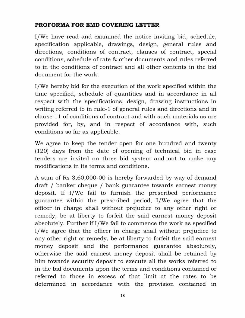
PROFORMA FOR EMD COVERING LETTER
I/We have read and examined the notice inviting bid, schedule,
specification applicable, drawings, design, general rules and
directions, conditions of contract, clauses of contract, special
conditions, schedule of rate & other documents and rules referred
to in the conditions of contract and all other contents in the bid
document for the work.
I/We hereby bid for the execution of the work specified within the
time specified, schedule of quantities and in accordance in all
respect with the specifications, design, drawing instructions in
writing referred to in rule-1 of general rules and directions and in
clause 11 of conditions of contract and with such materials as are
provided for, by, and in respect of accordance with, such
conditions so far as applicable.
We agree to keep the tender open for one hundred and twenty
(120) days from the date of opening of technical bid in case
tenders are invited on three bid system and not to make any
modifications in its terms and conditions.
A sum of Rs 3,60,000-00 is hereby forwarded by way of demand
draft / banker cheque / bank guarantee towards earnest money
deposit. If I/We fail to furnish the prescribed performance
guarantee within the prescribed period, I/We agree that the
officer in charge shall without prejudice to any other right or
remedy, be at liberty to forfeit the said earnest money deposit
absolutely. Further if I/We fail to commence the work as specified
I/We agree that the officer in charge shall without prejudice to
any other right or remedy, be at liberty to forfeit the said earnest
money deposit and the performance guarantee absolutely,
otherwise the said earnest money deposit shall be retained by
him towards security deposit to execute all the works referred to
in the bid documents upon the terms and conditions contained or
referred to those in excess of that limit at the rates to be
determined in accordance with the provision contained in
14
appropriate clause of the bid form. Further I/We agree that in
case of forfeiture of earnest deposit and performance guarantee
as aforesaid, I/We shall be debarred from participation in the re
bidding process of the work.
I/We undertake and confirm that eligible similar work(s) have not
been got executed through another contractor on back to back
basis. Further that if such a violation comes to the notice of the
officer in charge then I/We shall be barred for bidding in this
tender as well as in future forever. Also if such a violation is
noticed before the start of work, the in charge shall be free to
forfeit the entire amount of earnest money deposit/ performance
guarantee.
I/We hereby declare that I/We shall treat the bid documents,
drawings and other records connected with the work as secret
and confidential and shall not communicate information derived
there from to any person other than to whom I/We am/are
authorized to communicate the same or use the information in
any manner prejudicial to the safety of the state.
Dated:
Witness: Signature of contractor
Address:
Occupation Postal address
15
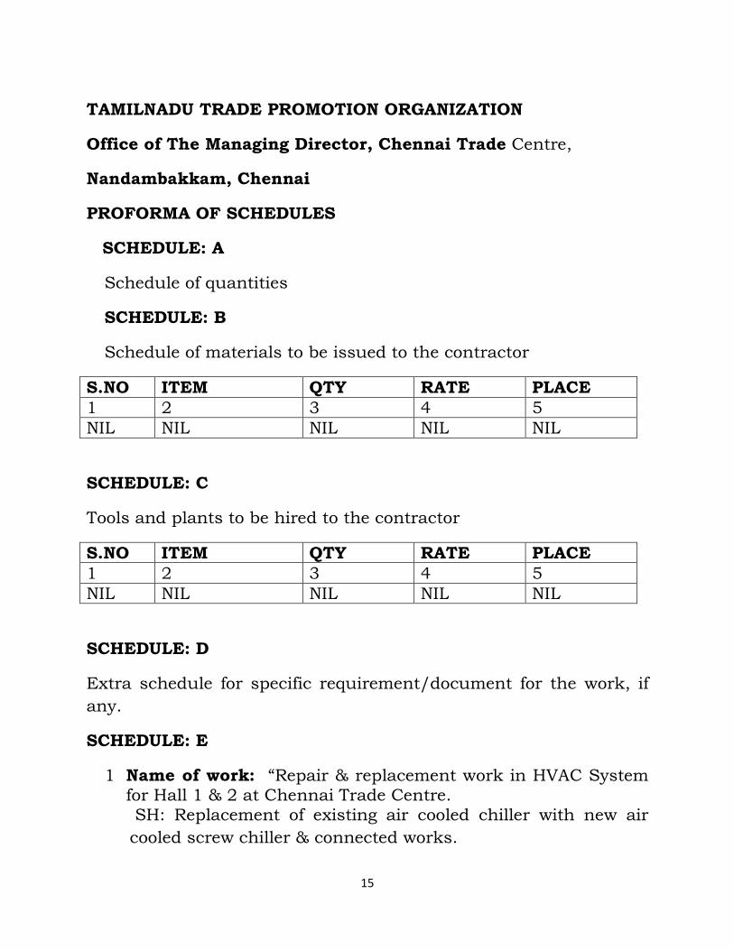
TAMILNADU TRADE PROMOTION ORGANIZATION
Office of The Managing Director, Chennai Trade Centre,
Nandambakkam, Chennai
PROFORMA OF SCHEDULES
SCHEDULE: A
Schedule of quantities
SCHEDULE: B
Schedule of materials to be issued to the contractor
S.NO ITEM QTY RATE PLACE
1 2 3 4 5
NIL NIL NIL NIL NIL
SCHEDULE: C
Tools and plants to be hired to the contractor
S.NO ITEM QTY RATE PLACE
1 2 3 4 5
NIL NIL NIL NIL NIL
SCHEDULE: D
Extra schedule for specific requirement/document for the work, if
any.
SCHEDULE: E
1 Name of work: “Repair & replacement work in HVAC System for Hall 1 & 2 at Chennai Trade Centre. SH: Replacement of existing air cooled chiller with new air
cooled screw chiller & connected works.
16
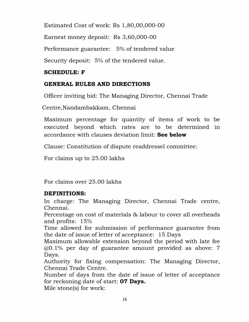
Estimated Cost of work: Rs 1,80,00,000-00
Earnest money deposit: Rs 3,60,000-00
Performance guarantee: 5% of tendered value
Security deposit: 5% of the tendered value.
SCHEDULE: F
GENERAL RULES AND DIRECTIONS
Officer inviting bid: The Managing Director, Chennai Trade
Centre,Nandambakkam, Chennai
Maximum percentage for quantity of items of work to be
executed beyond which rates are to be determined in
accordance with clauses deviation limit: See below
Clause: Constitution of dispute readdressel committee:
For claims up to 25.00 lakhs
For claims over 25.00 lakhs
DEFINITIONS:
In charge: The Managing Director, Chennai Trade centre, Chennai. Percentage on cost of materials & labour to cover all overheads and profits: 15% Time allowed for submission of performance guarantee from the date of issue of letter of acceptance: 15 Days Maximum allowable extension beyond the period with late fee @0.1% per day of guarantee amount provided as above: 7 Days. Authority for fixing compensation: The Managing Director, Chennai Trade Centre. Number of days from the date of issue of letter of acceptance for reckoning date of start: 07 Days. Mile stone(s) for work:

17
S.NO DESCRIPTION OF ITEM TIME ALLOWED
PENALTY
1 Supply of chiller at site 12 weeks 2% of chiller cost
2 Supply of materials for associated works
6 weeks 2% of associated work cost
3 Installation of chiller and associated works
6 weeks 2 % of total order value
4 Testing, commissioning and handing over
4 weeks 1% of the total contract value
Time allowed for execution of work: Five months.
Authority to decide extension of time, rescheduling of milestone:
The Managing Director, Chennai Trade Centre, Chennai.
Gross work to be done together with net payment/adjustment of
advances for material collected, if any since the last such payment
for being eligible for interim payment: Rs 5.00Lakhs.
Specification to be followed for execution of work: Technical
specification provided in this tender to be strictly followed.
Deviation limit beyond which rate determination is required for
additional quantity: 25%
Competent authority to decide on reducing rates: The Managing
Director, Chennai Trade Centre.
TAMILNADU TRADE PROMOTION ORGANIZATION
Office of The Managing Director, Chennai Trade Centre,
Nandambakkam, Chennai
18
AFFIDAVIT
I/We undertake and confirm that eligible similar work(s) has /
have not been got executed through another contractor on back
to back basis. Further that, if such a violation comes to the notice
of in charge then, I/We shall be debarred for tendering in
Chennai Trade Centre work in future forever. Also if such a
violation comes to the notice of incharge before the start of work,
the incharge shall be free to forfeit the entire amount of earnest
money deposit and performance guarantee.
Name & Signature of the contractor.
19
TAMILNADU TRADE PROMOTION ORGANIZATION
Office of The Managing Director, Chennai Trade Centre,
Nandambakkam, Chennai
AGREEMENT
To be signed by the bidder and same signatory competent /
authorized to sign the relevant contract on behalf of Chennai Trade
Centre
This Agreement is made at …………..on this……………day of………..
20………
BETWEEN
The Managing Director,…………………..
(Name of Division)
Chennai Trade Centre, ………………………………, (Hereinafter
referred as the
(Address of Division)
`Principal/Owner`, which expression shall unless repugnant to the
meaning or
context hereof include its successors and permitted assigns)
AND
…………………………………………………………………………..
(Name and Address of the Individual/firm/Company)
through………………………………………………… (Hereinafter referred
to as the
20
(Details of duly authorized signatory)
“Bidder/Contractor” and which expression shall unless repugnant
to the meaning or
context hereof include its successors and permitted assigns)
Preamble
WHEREAS the Principal / Owner has floated the Tender (NIT
No……………………..
…………….) (hereinafter referred to as “Tender/Bid’) and intends
to award, under
laid down organizational procedure,
contract for
…………………………………………………………………………………
(Name of work)
hereinafter referred to as the “Contract”
AND WHEREAS the Principal/Owner values full compliance with all
relevant laws of the land, rules, regulations, economic use of
resources and of fairness/transparency in its relation with its
Bidder(s) and Contractor(s).
AND WHEREAS to meet the purpose aforesaid both the parties have
agreed to enter into this Agreement (hereinafter referred to as
Agreement, the terms and conditions of which shall also be read as
integral part and parcel of the Tender/Bid documents and Contract
between the parties.
NOW, THEREFORE, in consideration of mutual covenants
contained in this Pact, the parties hereby agree as follows and this
Pact Witnesses as under:

21
Article 1: Commitment of the Principal/Owner
1) The Principal/Owner commits itself to take all measures
necessary to prevent corruption and to observe the following
principles:
(a) No employee of the Principal/Owner, personally or through any
of his/her family members, will in connection with the Tender, or
the execution of the Contract, demand, take a promise of or accept,
for self or third person, any material or immaterial benefit which
the person is not legally entitled to.
(b) The Principal/Owner will, during the Tender process, treat all
Bidder(s) with equity and reason. The Principal/Owner will, in
particular, before and during the Tender process, provide to all
Bidder(s) the same information and will not provide to any Bidder(s)
confidential / additional information through which the Bidder(s)
could obtain an advantage in relation to the Tender process or the
Contract execution.
(c ) The Principal/Owner shall Endeavour to exclude from the
Tender process any person, whose conduct in the past has been of
biased nature.
2) If the Principal/Owner obtains information on the conduct of any
of its employees which is a criminal offence under the Indian Penal
code (IPC)/Prevention of Corruption Act, 1988 (PC Act) or is in
violation
of the principles herein mentioned or if there be a substantive
suspicion in this regard, the Principal/Owner will inform the Chief
Vigilance Officer and in addition can also initiate disciplinary
actions as per its internal laid down policies and procedures.
22
Article 2: Commitment of the Bidder(s)/Contractor(s)
1) It is required that each Bidder/Contractor (including their
respective officers, employees and agents) adhere to the highest
ethical standards, and report to the Government / Department all
suspected acts of fraud or corruption or Coercion or Collusion of
which it has knowledge or becomes aware, during the tendering
process and throughout the negotiation or award of a contract.
2) The Bidder(s)/Contractor(s) commit himself to take all measures
necessary to prevent corruption. He commits himself to observe the
following principles during his participation in the Tender process
and during the Contract execution:
a) The Bidder(s)/Contractor(s) will no, directly or through any other
person or firm, offer, promise or give to any of the
Principal/Owner`s employees involved in the Tender process or
execution of the Contract or to any third person any material or
other benefit which he/she is not legally entitled to, in order to
obtain in exchange any advantage of any kind whatsoever during
the Tender process or during the execution of the Contract.
b) The Bidder(s)/Contractor(s) will not enter with other Bidder(s)
into any undisclosed agreement or understanding, whether formal
or informal. This applies in particular to prices, specifications,
certifications, subsidiary contracts, submission or non-submission
of bids or any other actions to restrict competitiveness or to
cartelize in the bidding process.
c) The Bidder(s)/Contractor(s) will not commit any offence under
the relevant IPC/PC Act. Further the Bidder(s)/Contract(s) will not
use improperly, (for the purpose of competition or personal gain), or
pass on to others, any information or documents provided by the
Principal/Owner as part of the business relationship, regarding
plans, technical proposals and business details, including
information contained or transmitted electronically.
23
d) The Bidder(s)/Contractor(s) of foreign origin shall disclose the
names and addresses of agents/representatives in India, if any.
Similarly Bidder(s)/Contractor(s) or Indian nationality shall disclose
names and addresses of foreign agents/representatives, if any.
Either the Indian agent on behalf of the foreign principal or the
foreign principal directly could bid in a tender but not both.
Further, in cases where an agent participate in a tender on behalf of
one manufacturer, he shall not be allowed to quote on behalf of
another manufacturer along with the first manufacturer in a
subsequent/parallel tender for the same item.
e) The Bidder(s)/Contractor(S) will, when presenting his bid,
disclose (with each tender as per proforma enclosed) any and all
payments he has made, is committed to or intends to make to
agents, brokers or any other intermediaries in connection with the
award of the Contract.
3) The Bidder(s)/Contractor(s) will not instigate third persons to
commit offences outlined above or be an accessory to such offences.
4) The Bidder(s)/Contractor(s) will no, directly or through any other
person or firm indulge in fraudulent practice means a willful
misrepresentation or omission f facts or submission of fake/forged
documents in order to induce public official to act in reliance
thereof, with the purpose of obtaining unjust advantage by or
causing damage to justified interest of others and/or to influence
the procurement process to the detriment of the Government
interests.
5) The Bidder(s)/Contractor(s) will not, directly or through any other
person or firm use Coercive Practices (means the act of obtaining
something, compelling an action or influencing a decision through
intimidation, threat or the use of force directly or indirectly, where
potential or actual injury may befall upon a person, his/her
24
reputation or property to influence their participation in the
tendering process).
Article 3: Consequences of Breach
Without prejudice to any rights that may be available to the
Principal/Owner under a law or the Contract or its established
policies and laid down procedures, the Principal/Owner shall have
the following rights in case of breach of this Integrity Pact by the
Bidder(S)/Contractor(s) and the Bidder/Contractor accepts and
undertakes to respect and uphold the Principal/Owner`s absolute
right:
1) If the Bidder(s)/Contractor(s), either before award or during
execution of Contract has committed a transgression through a
violation of Article 2 above or in any other form, such as to put his
reliability or credibility in question, the Principal/Owner after giving
14 days notice to the contractor shall have powers to disqualify the
Bidder(s)/Contractor(s) from the Tender process or
terminate/determine the Contract, if already executed or exclude
the Bidder/Contractor from future contract award processes. The
imposition and duration of the exclusion will be determined by the
severity of transgression and determined by the Principal/Owner.
Such exclusion may be forever or for a limited period as decided by
the Principal/Owner.
2) Forfeiture of EMD/{performance Guarantee/Security Deposit:
If the Principal/Owner has disqualified the Bidder(s) from the
Tender process prior to the award of the Contract or
terminated/determined the Contract or has accrued the right to
terminate/determine the Contract according to Article 3(1), the
Principal/Owner apart from exercising any legal rights that may
have accrued to the Principal/Owner, may in its considered opinion
forfeit the entire amount of Earnest Money Deposit, Performance
Guarantee and Security Deposit of the Bidder/Contractor.
25
3) Criminal Liability: If the Principal/Owner obtains knowledge of
conduct of a Bidder or Contractor, or of an employee or a
representative or an associate of a Bidder or Contractor which
constitutes corruption within the meaning of Indian Penal code
(IPC)/Prevention of Corruption Act, or if the Principal/Owner has
substantive suspicion in this regard, the Principal/Owner will
inform the same to law enforcing agencies for further investigation.
Article 4: Previous Transgression
1) The Bidder declares that no previous transgressions occurred in
the last 5 years with any other Company in any country confirming
to the anticorruption approach or with Central Government or State
Government or any other Central/State Public Sector Enterprises in
India that could justify his exclusion for the Tender Process.
2) If the Bidder makes incorrect statement on this subject, he can
be disqualified from the Tender process or action can be taken for
banning of business dealings/holiday listing of the
Bidder/Contractor as deemed fit by the Principal/Owner.
3) If the Bidder/Contractor can prove that he has resorted /
recouped the damage caused by him and has installed a suitable
corruption prevention system, the Principal/Owner may, at its own
discretion, revoke the exclusion prematurely.
Article 5: Equal Treatment of all
Bidders/Contractors/Subcontractors
1) The Bidder(S) Contractor(s) undertake(s) to demand from all
subcontractors a commitment in conformity with this agreement.
The Bidder/Contractor shall be responsible for any violation(s) of
the principles laid down in this agreement/Pact by any of its Sub-
contractors/sub-vendors.
26
2) The Principal/Owner will enter into Pacts on identical terms as
this one with all Bidders and Contractors.
3) The Principal/Owner will disqualify Bidders, who do not submit,
the duly signed Pact between the Principal/Owner and the bidder,
along with the Tender or violate its provisions at any stage of the
Tender process, from the Tender process.
Article 6-Duration of Pact
This Pact begins when both the parties have legally signed it. It
expires for the Contractor/Vendor 12 months after the completion
of work under the contract or till the continuation of defect liability
period, whichever is more and for all other bidders, till the contract
has been awarded.
If any claim is made/lodged during the time, the same shall be
binding and continue to be valid despite the lapse of this Pacts as
specified above, unless it is discharged/determined by the
Competent Authority, Chennai Trade Centre.
Article 7-Other Provisions
1) This Pact is subject to Indian Law, place of performance and
jurisdiction is the Head quarters of the Division of the
Principal/Owner, who has floated the Tender.
2) Changes and supplements need to be made in writing. Side
agreements have not been made.
3) If the Contractor is a partnership of a consortium, this Pact must
be signed by all the partners or by one or more partner holding
power of attorney signed by all partners and consortium members.
In case of a Company, the Pact must be signed by a representative
duly authorized by board resolution.
4) Should one or several provisions of this Pact turn out to be
invalid; the remainder of this Pact remains valid. In this case, the
27
parties will strive to come to an agreement to their original
intensions.
5) It is agreed term and condition that any dispute or difference
arising between the parties with regard to the terms of this
Agreement / Pact, any action taken by the Owner/Principal in
accordance with this Agreement/Pact or interpretation thereof shall
not be subject to arbitration.
Article 8-LEGAL AND PRIOR RIGHTS
All rights and remedies of the parties hereto shall be in addition to
all the other legal rights and remedies belonging to such parties
under the Contract and/or law and the same shall be deemed to be
cumulative and not alternative to such legal rights and remedies
aforesaid. For the sake of brevity, both the Parties agree that this
Integrity Pact will have precedence over the Tender/Contact
documents with regard any of the provisions covered under this
Integrity Pact.
IN WITNESS WHEREOF the parties have signed and executed this
Integrity Pact at the place and date first above mentioned in the
presence of following witnesses:
…………………………………………
(For and on behalf of Principal/Owner)
…………………………………………..
(For and on behalf of Bidder/Contractor)
WITNESSES:
28
1. ………………………………….
(signature, name and address)
2. ………………………………….
(signature, name and address)
Place:
Dated:
BANK GUARANTEE BOND
Form of Earnest Money Deposit
Bank Guarantee Bond
WHEREAS, contractor………………… (Name of Contractor)
(hereinafter called “the contractor”) has submitted his tender
dated ……….. (date) for the construction of
………………………………… (name of work) (hereinafter called
“the Tender”)
KNOW ALL PEOPLE by these presents that we …………………
(name of bank) having our registered office at
…………………………… (hereinafter called “the Bank”) are bound
unto ………………………..
29
(Name of the Managing Director) (herein after called “the
Director-in-Charge”) in the sum of Rs. ………… (Rs. in words
…………………………………………) for which payment well and
truly to be made to the said Director-in-Charge the Bank binds
itself, his successors and assigns by theses presents.
SEALED with the Common Seal of the said Bank this
…………..day of………….
20……
THE CONDITIONS of this obligation are:
(1) If after tender opening the Contractor withdraws, his tender
during the period or validity of tender (including extended
validity of tender) specified in the Form of Tender;
(2) If the contractor having been notified of the acceptance of
his tender by the Director-in-Charge:
(a) fails or refuses to execute the Form of Agreement in
accordance with the Instructions to contractor, if required;
OR
(b) fails or refuses to furnish the Performance Guarantee, in
accordance with provisions of tender OR
( c) fails or refuses to start the work, in accordance with the
provisions of the contract and instructions to contractor,
OR
(d) fails or refuses to submit fresh Bank Guarantee of ;an equal
amount of this Bank Guarantee, against Security Deposit after
award of contract.
We undertake to pay to the Director-in-Charge up to the above
amount upon receipt of his first written demand, without the
Director-in-Charge having to substantiates his demand,
provided that in his demand the Director-in-Charge will note
30
that the amount claimed by his is due to him owing to the
occurrence of one or any of the above conditions, specifying
the occurred condition or conditions.
This Guarantee will remain in force up to and including the
date* ………… after the deadline for submission of
tender as such deadline is stated in the Instructions to
contractor or as it may be extended by the Director-in-Charge,
notice of which extension(s) to the Bank is hereby waived. Any
demand in respect of this Guarantee should reach the Bank not
later than the above date.
DATE……………..
SIGNATURE OF THE BANK
WITNESS………………
SEAL
(SIGNATURE, NAME AND ADDRESS)
*Date to be worked out on the basis of validity period of 6
months from last date of receipt of tender.
31
ANNEXURE-I
Additional Conditions and Technical Specifications
SPECIAL INSTRUCTIONS:
a. The tenderer is requested to ensure that all schedules are filled
in and information is supplied in the prescribed format/schedules.
Failure to do so will render the tender incomplete and liable for
rejection.
b. Should the tenderer wish to depart from the provisions in this
specification, commercial or technical, such departures should be
listed out in Annexure-I appended and submit full particulars and
reasons for the departure.
c. The tenderer is advised to visit the site for collecting any
additional information for purposes of working out his offer.
d. The AC equipments shall be supplied and installed at
Chennai Trade center at Trade centre Campus, Nandambakkam,
Chennai.
e. The Address of the officers of the Chennai Trade Centre
connected with this work is given below:
The Managing Director, Tamil Nadu Trade Promotion
Organization, Office of the Managing Director, Chennai Trade
Centre, Nandambakkam, Chennai.
32
SECTION-1
1.1. SCOPE:
This specification covers general information and particulars
relating to this specification.
1.2. WORK COVERED BY THIS SPECIFICATION:
This specification covers procurement, fabrication, testing
as may be necessary before dispatch, installation, wiring, testing
and commissioning of all the items of work. This detailed
specification will form part of the works contract with the
successful tenderer.
1.3. LOCATION
The plant and equipment are to be installed at TNTPO, The
Chennai Trade Centre, Nandambakkam, Chennai.
1.4. RELATED DOCUMENTS:
This specification shall be read in conjunction with the
CPWD general specifications for Electrical works-Part-I (Internal)
2007 Part-II (External) 1995. For technical matters and with the
standard conditions of the contract appended with amendments for
other matters as well as with schedules and drawings and
requirements under this specification. In the event of any
discrepancies between this specification and inter-connected
documents, the specific requirements as per this specification shall
be followed and deemed to be having over riding value and the
decision of The Director, Chennai Trace centre will be final in this
regard.
33
1.5. MODE OF SUBMISSION OF TENDER
a) The hard copy of the tender shall be submitted to Office of
The Managing Director, The Chennai Trade Centre,
Nandambakkam, Chennai.
b) On confirmation of the receipt of The Cost of tender,
Processing Fee payable to Chennai Trade Center, Chennai, and The EMD the Prequalification documents will be opened and will be scrutinized by the competent authority. On approval from competent authority, the technical bid of those approved firms shall only be opened on the date and time to be intimated separately in the presence of the intending tenderer or their authorised representative who wish to be present. The price bids of only those tenderer whose technical-cum-commercial bids are found acceptable by the competent authority and shall be opened on the date and time to be intimated subsequently.
c) The scrutiny and evaluation of technical-cum-commercial bids shall be done by the department or its authorised professional and the tenderer shall furnish necessary clarifications/ confirmation/additional information as required by the department or its authorised professional within the stipulated time. d) Revised price bids, if required, due to changes in the tendered specifications, terms and/or conditions shall be given in a sealed envelope suitably super scribed with the name of the work and the words "Revised price bid" by the tenderer before the stipulated date and time.
1.6. EMD: - EMD in the acceptable form shall be submitted along with the tender in a separate sealed envelope .Tenders submitted with out EMD will not be opened.
1.7 DATE OF ACCEPTANCE
The date of successful completion of the prescribed testing at site after installation and handing over the installation to the department shall be taken as the date of completion of the work. The warranty/free maintenance period will commence from this date.
34
1.8 PERFORMANCE GUARANTEE The tenderer shall guarantee among other things, the following: a) Quality, strength and performance of the materials used. b) Satisfactory operation during the warranty period.
1.9 COMPLETION PERIOD
The entire supply and installation testing and commissioning shall be completed in all respects and handed over to the department within the period specified in Form attached.
1.10 INSPECTION AND TESTING i) The authority's authorized representative shall have full
powers to inspect drawings of any portion of the work, examine the materials and workmanship of the contractor works/manufacturing site or at any other place from which the material or equipment is obtained. Acceptance of any material/equipment shall in no way relieve the contractor of his responsibility for meeting the requirement of specifications but shall have to be rectified by the contractor in case the equipment or work is found defective or of inferior quality.
ii) Routine type tests for various items of equipment shall be
performed at the contractor's works /manufacturer's place and test certificates furnished. The contractor shall permit the authority's authorized representative to be present during any or all these tests. After notification to the authority that the installation has been completed .the contractor shall make under the direction in the presence of Engineer in charge such tests and inspection as have been specified or as the Engineer in charge shall consider necessary to determine whether or not the full intent of requirements of the plans and specifications have been fulfilled. In case the work does not meet the full intent of specifications, it shall be rectified by the contractor at no extra cost and the contractor shall bear all expenses for any further tests considered necessary. Prior to the dispatch of the chiller from the factory witness test must be offered by the manufacturer in their AHRI certified test bed (one point load test). All the expenses such as travel, boarding, lodging, conveyance etc towards such test have to be borne by the supplier /contractor.
iii) All the tools, instrument, plants and labour /operating personnel for the test shall be provided by the contractor at his own cost.
35
iv) Rejection of defective plant/inspection. If the complete work/equipment or any portion thereof before it is taken over is found defective or fails to fulfill, the intent of specification, the contractor shall, on receipt of a written notice from Managing Director in charge forthwith make good the defective work/equipment. Should the contractor fail to rectify the defects and or make good the defective work/equipment with in a stipulated time mentioned in the written notice, or replace the equipment at no extra cost to the authority, the authority may make good project and /or replace at the risk and expenses of the contractor the whole or any portion of the work/equipment which is defective or fails to fulfills requirement of the contract. The authority shall have the right to operate all equipments in any operating conditions whether or not such a equipment have been accepted as complete and satisfactory. Repairs and alteration shall be made at such times and as directed by the Managing director in charge.
36
SECTION-II
C. COMMERCIAL INFORMATION
2.1 SCOPE This section covers the general commercial aspects for the
work covered by this specification. This shall be supplementary to the general conditions of contract.
2.2 TYPE OF CONTRACT:
The work awarded by this specification shall be treated as indivisible works contract.
2.3 2.3 TAXES AND DUTIES No sales tax and duties such as Excise Duty, Octroi etc. shall be payable separately. No Certificate for exemption/concession like form 'D',‘C’/ Octroi etc will be issued by the Director Incharge. Tenderer may however indicate the quantum of taxes/duties etc. included by him and their rates and basis, in the price quoted. 2.4 Income Tax @ 2% shall be recoverable from every bill on the labour value of work done. 2.5 Service tax payable on this contract shall be paid by the contractor to the concerned department. In no cases taxes, duties and other levies will be paid by The Director, Chennai Trade Centre.
2.5 PRICES
Prices quoted shall be firm for the contract period or till
the period of completion of work.
Nothing extra shall be payable on this value after
opening of the price bid.
2.6 VALIDITY Tenders shall be valid for acceptance for a period of 120
days from the date of opening of the technical bid.
37
2.7 FACILITIES AVAILABLE AT SITE 415volts,3 ph 50 cycles 4 wire supply will be made
available to the successful tenderer for operation of small equipments required for the installation of the above system such as tools, welding sets, etc.., at one point at a charge of 0.5% of the quoted value. Necessary distribution to all the working areas wherever it is required by the contractor shall be taken care by the contractor at his own cost. Necessary water during installation period as will be made available at free of charge. Suitable open storage space will be made available at site free of cost. However construction of shed, watch and ward of the stores shall be the sole responsibility of the tenderer. No tools and tackles either for unloading or for shifting the equipment or for erection purpose would be made available by the Department. The successful tenderer shall make their own arrangement for all these facilities.
2.8 COOPERATION WITH OTHER AGENCIES: Successful tenderer shall co-ordinate with other contractors and agencies engaged in the revamping, if any and exchange freely all technical information so as to make the execution of works contract smooth. No remuneration should be claimed from the Department for such technical co- operation.
2.9 WARRANTY
All equipments supplied and installed shall be covered by warranty for 12 months effective from the date of acceptance against defective workmanship and materials. If any equipment is found to be defective due to fault) workmanship, faulty materials, faulty design or inferior quality of materials during the warranty period it shall be repaired and/ or replaced at site free of charge by the successful tenderer at his own cost. The warranty shall cover consequential damages to the equipments supplied and installed by the tenderer due to poor workmanship or defective materials. All repairs shall be done promptly within a reasonable period.
2.10 TERMS OF PAYMENT.
Payment term shall be as under
70% against completion of supply of material at site.
38
20% against completion of installation and successful
commissioning.
05% against handing over of the complete system.
05% against defect liability period of 24 months from the date
of handing over.
Security deposit @ 5% will be deducted in each running bill and
the same will be released along with the final bill.
2.11 BUY BACK OF OLD CHILLER:
Vendor has to offer buy back arrangement of old chillers 6Nos
of 75TR available at site. It would be the responsibility of the
vendor to dismantle or remove the chillers as and when it is
cleared by Chennai trade centre for removal without affecting
the property of trade centre and its working. The offer given by
the vendor will be adjusted in the contract value of the
proposed work.
2.12 Work front & Schedule of planning:
As the Chennai Trade Centre has continuously booking of
Exhibition Hall No.1 & 2 throughout the year, it is prime
responsibility of successful tenderer to take care of the bookings
after consultation with the TNPO officials and then to prepare the
plan of activity for the replacement of chillers without affecting the
forthcoming Exhibitions in Hall No.1 & 2. Hence the successful
vendor need to carefully study the requirement and accordingly
plan their activity to remove the old chillers and install and
commission the new chillers without affecting the business
schedule of the centre.
39
SECTION III TECHNICAL – GENERAL REQUIREMENTS
3.1 SCOPE:
This section covers the general technical requirements to be complied with in respect of the works contract.
3.2 COMPLETENESS OF TENDER:
All fittings, unit assemblies, accessories, hardware foundation bolts, terminal lugs for electrical connections, cable glands and miscellaneous materials or accessories or items of work which are useful and necessary for efficient assembly and working of the equipment shall be deemed to be included in the tender within the overall cost quoted. The equipment shall be complete in all details whether such details have been mentioned or not.
3.3. TEST CERTIFICATES:
Copies of all documents of routine and type test certificate of the equipment carried out at manufacturers premises shall be furnished, as required.
3. 4 PAINTING: The tendered cost shall include cost of painting of entire iron works complete in the completed installation. All factory fabricated machinery shall be painted before dispatch to the site at the shop with two coats of anti-corrosive primer paint duly finished with powder coating. All iron works fabricated at site shall be painted with two coats of anti-corrosive primer paint and two coats of synthetic enamel paint. 3.5 STANDARDS
The tenderer shall clearly state in his offer standards adopted for the design and manufacture of the equipment and the components. All electrical equipment shall conform to latest Indian Electricity Regulations as regards safety, earthing and other provisions specified therein for installation and operation of the electrical plant. The equipment shall also conform to detailed requirements under this specification, in particular. Any deviation made by the tenderer should clearly bring out under

40
“schedule B” giving reasons for the deviation as well as explaining how the deviations would add to an approved performance.
3.6 GENERAL WORKMANSHIP
All manufactured/fabricated items shall conform to good workmanship and shall comply with the best commercial standards for ruggedness of construction.
41
SECTION-IV
GENERAL CONDITIONS
4.0 GENERAL INFORMATION:
4.0 The Special/Particular Instructions and Conditions of Contract as described in this document are intended to amplify the General conditions of Contract and shall be read in conjunction with specifications of work, drawings and all other documents forming part of this Contract wherever the context so requires. In case of any ambiguity between clauses pertaining to the same subject, in the general conditions or any other sections including this section, the most stringent of them shall apply. The following clauses shall be considered as an extension and not in limitation of obligation of the Contractor.
4.2 All expenses incurred by the tenderer in connection with obtaining information for submitting this tender including his visits to the site or efforts in compiling the tender shall be borne by the tenderer and no claims for reimbursement thereof shall be entertained.
4.3 Not withstanding the sub-division of the documents into separate sections and volumes every part of each shall be deemed to be supplementary to and complementary of every other part and shall be read with and into the CONTRACT so far as it may be practicable to do so.
4.4 Wherever it is mentioned in the specification, that the CONTRACTOR shall perform certain work or provide certain facilities, including factory witness testing, it is understood that the CONTRACTOR shall do so within the tendered amount.
4.5 TECHNO COMMERCIAL CONDITIONS
4.5.1. Information Documents to be submitted with Contractor’s proposal
The Tender should contain
a) Power and water requirements.
42
b) Tenderer shall include all relevant technical particulars for the equipments offered by them. Furnish computer printout selection of chiller unit, compressor selection indicating IKW/Ton at full load and part load CONDITIONS based on specific parameters.
c) Technical Data sheet duly filled-in with all particulars of mechanical features / dimensioned data / operating parameters. Failure to provide technical data the tender will be rejected.
d) Design confirmation by contractor.
e) Confirmation on satisfactory’ operation of chiller unit at ambient temp 40 deg.C.
f) Complete tender document as collected from the Engineer-in-charges including the schedule of quantities thereof duly signed for acceptance of all terms and conditions.
g) Particulars of Engineers and technical staff proposed to be deployed for working on the site along with their qualifications and experience should be submitted after the award of work.
h) Information on the quantity of refrigerant charge should be indicated in the selection sheet.
4.6 Declaration:
The bidder when submitting his bid shall be deemed to have declared as follows: I / We hereby declare that I/We shall treat the tender documents, drawings and other records connected with the work as secret confidential documents and shall not communicate information derived there from to any person(s) other than a person to whom I / We am/are authorised to communicate the same or use the information in any manner prejudice to the safety of the same.
43
4.7 Important Note: The tenderer is required to pursue carefully all parts of tender documents and drawings. If any differences / inconsistency is noted, he shall bring it to the attention of Engineer in charge before submission of the Tender and shall get clarifications required
4.7.1. Refrigerant:
The offers invited in this tender for the chiller Unit are based on refrigerant R410a / R407c or R134a. The tendered are instructed to restrict in quoting for only one refrigerant based system. Revising the tender at a later date is not permitted once the technical bid is opened.
4.8 CONSTRUCTION PROGRAMME:
4.8.1 The Contractor must follow his planning schedule and must adhere to the targets/ program by deploying adequate resources.
4.8.2 The Contractor shall 43 ictauli all plant, machineries, equipments etc. required to adhere to the time schedule of various activities and events as per Bar Chart / PERT Chart/CPM Chart and well in advance.
4.8.4 Occupation in Part: If the Department wants to occupy areas in part, the contractor shall complete the work of these areas in conjunction with the Department and handover the same to the Department without affecting any of the clauses of contract agreement.
4.9 OBLIGATION OF CONTRACTOR:
The obligation of the contractor is to fulfill in this Contract are stated below: 1. Detailed Engineering including the complete
revamping work involved in the system. 2. Procurement, fabrication and supply
44
3. Inspection and testing, expediting and Co-ordinating with other agencies
4. Scheduling and Monitoring, training the Clients worker / representative in the operation and maintenance.
5. Erection, checking and testing and commissioning. 6. Providing Guarantee
7. Final documentation 8. Maintenance during defects liability period.
4.10 It is only after the entire plant assembly has been thoroughly checked up on the lines indicated above and found satisfactory that erection work shall deemed to be completed and the plant considered READY FOR COMMISSIONING. The system shall be commissioned only after contractor has certified in writing that the electrical installation work for services has been thoroughly checked, tested and found to be totally satisfactory and in full conformity with the contract drawings, specifications and manufacturer’s instructions.
4.11 The contractor shall also guarantee that performance of various equipments, individually shall not be less than the quoted capacity, also actual power consumption shall not exceed the quoted rating.
4.12 Rates indicated in schedule of rate shall also cover for all activities listed above.
4.13 DRAWINGS AND LITERATURE:
The Contractor shall furnish three copies of following detailed working drawings for approval by the Engineer-in-Charge/Department within 10s days from the date of Award of Contract. No installation work at site shall be taken up till the installation drawings are approved. For this purpose, he shall submit 6 sets of the following drawings to the Managing Director –in – charge. The Contractor shall incorporate any alterations proposed by the Managing Director – in – charge, in the drawings and the corrected drawings shall be submitted once again in 3 sets to the Department. The working drawings to be submitted by the Contractor shall comprise all aspects as detailed below. Prior to the preparation of detailed working drawings the contractor shall check actual site condition/ specifications and shall with in seven days report any error, discrepancies and or
45
omission discovered therein to Engineer in charge and obtain appropriate orders on the same .Any adjustments made by the contractor without prior approval of the department shall be at his own risk, and cost. Prior to submission or approval the contractor shall be responsible for thoroughly checking all drawings to ensure that they comply with the intent and their requirements of the contract specifications and that fit in with the overall building layout.
1. Complete installation drawings showing details
of chiller Plant, chilled water pipeline layout including sizes, air distribution grills / jet nozzles layout, electrical cabling, earthing along with main panel with sizes and electrical circuits.
b. Detailed drawings of civil works, such as foundations required for the installation of chiller.
4.14 After approval further six copies of drawings should be furnished with in 10days from the date of approval of the drawings
4.15 Approval of the drawings does not relieve the Contractor of any part of his obligation to meet all the requirements of the contract or his drawing.
4.15.The Contractor shall be responsible for and pay for all alterations of the work due to the discrepancies or omissions in the drawings or other particulars supplied by him whether such drawings have been approved by the Engineer-in-charge or not.
4.16.The specifications, drawings and other parts of this Contract are to be considered as explanatory to each other and should anything appear in the one that is not described in the other or should any discrepancy of any inconsistency appear between any two or more parts of the Contract, and any misunderstanding arise on account of such discrepancy or inconsistency, the site instructions given by the Engineer-in-charge shall prevail. The Contractor shall execute the work according to such instructions/explanations and given by the different parts of this Contract even though such works are not specifically shown and described therein. After installation is completed, 8 sets of “As-built” drawings shall be prepared in full details and submitted to Engineer-in-charge within 3 weeks from the date of completion of installation.
46
4.17. Six copies of comprehensive manual (operation, maintenance and service) of the equipments for use before and during erection and subsequent application shall also be furnished within 7 days from the date of approval of the drawings.
Contractor shall furnish and install in the location as decided by the Managing Director – in – charge, a neatly typed set of operating instructions maintenance schedule and a copy of Electrical wiring diagram for the plant, securely framed and glazed. Also the following information mounted on a frame shall be displayed.
a. Name and make of the chiller
b. Model of the equipment.
c. Name and full charge of the refrigerant. d. Name and full charge of oil e. Date of commissioning.
4.18 The Contractor shall if called upon, also furnish necessary electrical wiring diagram to meet the requirements of the Electricity authorities.
4.19 PROJECT CO-ORDINATION:
All Contractors and subcontractors shall coordinate their activities for their mutual benefit and shall cooperate to facilitate the general progress of the work. Inspect the contract documents for work of others that is interrelated with the work. Afford all other trades every reasonable opportunity for the installation of their work.
4.20 Perform the work in proper sequence and arrangement in relation to other activities and join the work to that of others in accordance with the intent of the drawings and specifications. Give due notice and proper information for any special provisions necessary in the placing or setting of the work which may come in contact with work of other Contractors.
4.21 Arrange the work and dispose of materials so as not to interfere with the work or storage of materials of others.
47
4.22 All Contractors shall work in cooperation with each other and fit their piping, duct work, conduit, etc., into the structure as job conditions may demand.
4.23 All final decisions as to the right-of-way and run of interfering pipes, ducts, etc., shall be made by the Engineer-in-charge at project meetings with responsible representatives of the various Contractors. .
4.24 DELIVERY SCHEDULE:
The contractor shall be responsible for delivery of all plant, machines and equipments both from their factory and from their suppliers and shall ensure delivery in the sequence in which they will be required at site for erection. The contractor shall submit unit performance data for approval before delivering.
48
SECTION – V
SPECIAL TECHNICAL CONDITIONS
5.0 SAFETY All equipment shall be complete with approved safety devices wherever a potential hazard to personnel exists, and with provision for safe access of personnel to and around equipment for operational and maintenance functions. These items shall include not only those usually furnished with elements of machinery, but also the additional covers, guards, cross-covers, stairways, ladders, platforms, handrails etc., which are necessary for safe operation of the plant. The Contractor shall include for all safety items including, but not limited to the following.
5.1 NOISE LEVEL: All refrigeration and air conditioning equipment and materials (like motors, compressors, fans, ducts, grilles, acoustic lining etc,) shall be selected, designed and installed in such a manner that low noise is maintained as per specification.
5.2 VIBRATION ELIMINATORS:
I) All the mechanical equipment shall be mounted in accordance with the specifications detailed below:
a) All machinery and equipment shall be installed on MS Channel frame work.
b) The vibration isolation for equipment will be supplied by the Contractor to suit his equipment. The supply should include all unit isolators, complete rails, equipment base and structural steel frames for concrete inertia blocks, wherever required.
c) Wherever rotational speed is reckoned as the disturbing frequency, the lowest speed shall be taken for calculation purpose. All isolation devices shall be
49
selected for uniform static deflection, according to distribution of weight.
Ill) All mechanical equipment should be mounted on
vibration eliminators. No duct and piping shall be grouted in walls. Isolation sleeves shall be incorporated at all points where ducts/pipes pierce through walls.
5.3 TESTING
After manufacture of the equipment all necessary routine test shall be carried out as per relevant Indian or any suitable standards and as listed in respective section.
Routine test for various items of equipment shall be performed at the Contractor works and test certificates shall be furnished. If required by the Department, his authorized representative shall be permitted to be present during any of the tests. After notification to the Department that the installation has been completed, the Contractor shall make under the direction of Department such tests and inspections as have been specified or as the Department shall consider necessary to determine whether or not the full intent of the specifications have been fulfilled and whether further tests shall be considered necessary. The Contractor shall bear all the expenses thereof. Any damage resulting from the tests shall be repaired and / or damaged material replaced, to the satisfaction of the Department’s representative. The contractor shall operate, test and adjust all Air conditioning, ventilation and exhaust system units, fan motors, all air handling appliances provided in connection with the installation and shall make all necessary adjustments and corrections thereof including the adjustments of all regulating dampers. A carefully detailed record of the results of these adjustments shall be furnished to and be subject to the approval of the Department.
50
5.4 PERFORMANCE TEST Upon notification to the Engineer-in-charge/ from the Contractor, that the installation has been completed, the Contractor shall conduct under the direction and in the presence of the Engineer-in-charge or his representatives, performance test on the plant as per the Proforma furnished in the clause no. 5.5 test readings such inspections and tests as the Engineer-in-charge shall consider necessary to determine whether or not the full intent of the requirements of the plant and specifications have been fulfilled. The date of commencement of all testing listed herein, shall be subject to the approval of the Department and in accordance with the requirement of the Department’s representative. A performance test by keeping the plant running for a period of 72 hrs shall be carried out in peak summer and peak monsoon periods. During the tests, reading shown in 5.5 Test readings shall be taken hourly. From the readings so taken, the Contractor shall also establish the plant capacity. All the test equipment, instruments, labour, operating personnel, oil and refrigerant required for these tests shall be furnished by the Contractor at his own cost. In case the work does not meet the full intent of the specification or if the test do not show satisfactory result, the Contractor shall at his own cost, rectify/replace the defective installation or part thereof as directed by the Department within two months. The contractor shall bear all expenses thereof. The decision of the Department shall be final and binding in this respect. Only after all these tests are satisfactorily completed and the defects found during these are rectified, the plant will be finally accepted.
5.5 TEST READINGS:
The following readings shall be taken (and results computed) during the performance tests on the plant. The contractor shall provide such assistance, instruments, machines, labour and materials as are normally required for examining, measuring and test.
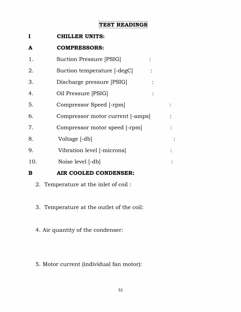
51
TEST READINGS
I CHILLER UNITS:
A COMPRESSORS:
1. Suction Pressure [PSIG] :
2. Suction temperature [-degC] :
3. Discharge pressure [PSIG] :
4. Oil Pressure [PSIG] :
5. Compressor Speed [-rpm] :
6. Compressor motor current [-amps] :
7. Compressor motor speed [-rpm] :
8. Voltage [-db] :
9. Vibration level [-microns] :
10. Noise level [-db] :
B AIR COOLED CONDENSER:
2. Temperature at the inlet of coil :
3. Temperature at the outlet of the coil:
4. Air quantity of the condenser:
5. Motor current (individual fan motor):
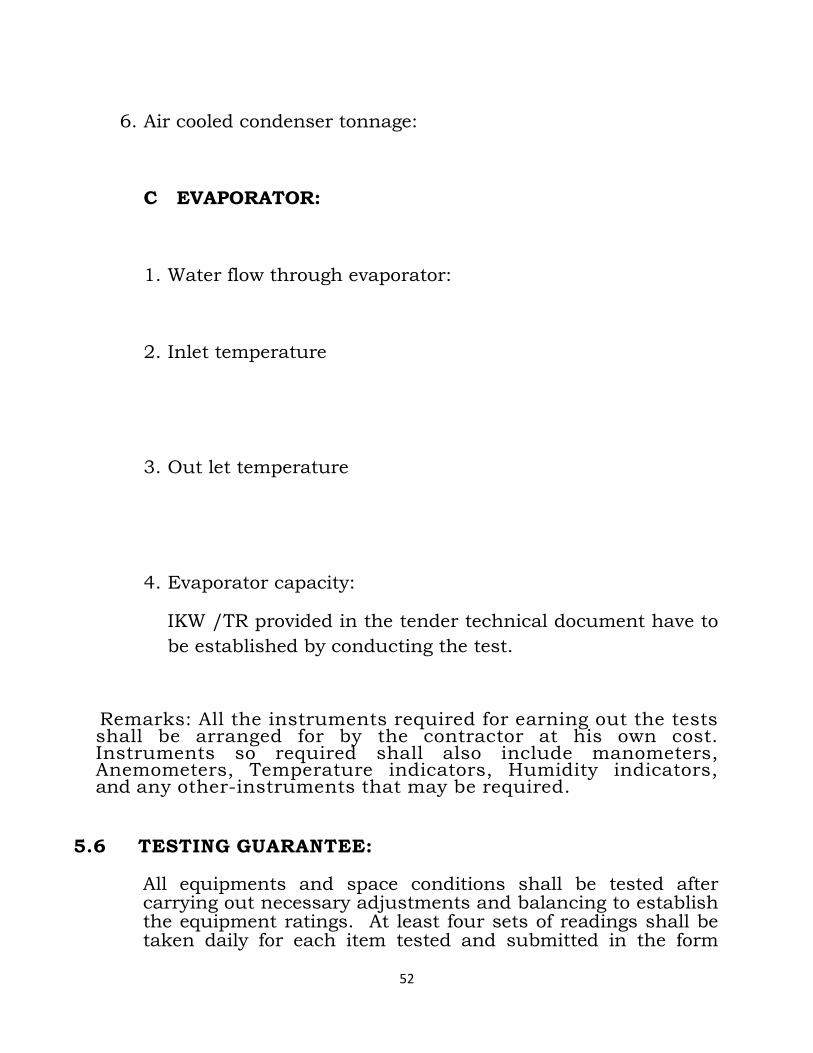
52
6. Air cooled condenser tonnage:
C EVAPORATOR:
1. Water flow through evaporator:
2. Inlet temperature
3. Out let temperature
4. Evaporator capacity:
IKW /TR provided in the tender technical document have to
be established by conducting the test.
Remarks: All the instruments required for earning out the tests shall be arranged for by the contractor at his own cost. Instruments so required shall also include manometers, Anemometers, Temperature indicators, Humidity indicators, and any other-instruments that may be required.
5.6 TESTING GUARANTEE: All equipments and space conditions shall be tested after carrying out necessary adjustments and balancing to establish the equipment ratings. At least four sets of readings shall be taken daily for each item tested and submitted in the form
53
shown separately. All equipment shall be guaranteed for the specified ratings plus or minus 3% tolerance. All equipments and the entire installation shall be guaranteed against defective materials and workmanship for a period of 12 months from the date, the equipment and installation are handed over.
5.7 TEST REPORTS: Test reports shall be neatly typed on forms similar to those recommended by the Engineer-in-charge. As per the Test report the forms shall include but not be limited to the following information:
1) Name of job. 2) Name of Agency 3) Date of test and outdoor temperature 4 ) Name of technician making tests. 5) List of test instruments used. 6) Identification of all units with location,
manufacturer’s name, model number and serial number. 7 ) Information on all motors with manufacturer’s
name, model number, horsepower, rpm, voltage, rated current, actual
current. 8 ) CMH readings as designed, as originally measured
and actual final reading and duct transverse sheets for each major
zone. 9) Register, grille and diffuser list with room number,
manufacturer’s model number, size area, design cfm. Design
velocity and test results. 10) Coil list with coil size, manufacturer’s name and
model number and with design and actual readings of cfm. Gpm. Air friction, water pressure drop thru coil, dry bulb and wet bulb temperatures.
5.8 REPORTS
Provide 3 copies of the complete balancing and testing reports to the department. Report shall be neatly typed and bound suitable for a permanent record. Report forms
54
shall contain complete test data and equipment data as specified.
5.9 GUARANTEED PERFORMANCE
The Contractor shall guarantee the inside conditions as stipulated elsewhere. In addition, the Contractor shall also guarantee that all equipment shall be free from any defect due to the defective materials/faulty design materials and bad workmanship and that the equipment shall operate
Satisfactorily and the performance and efficiencies of the equipment shall be not less than the guarantee values.
The guarantee shall be valid for a period of 12 months after taking over and any parts found defective during this period shall be replaced free of all costs by Contractor. Five years warranty for replacement of compressors including material and labor shall be provided for imported chilling units. The services of successful Contractor’s personnel if requisitioned by the Department
during this defects liability period for such work shall be made available free of any cost.
5.10 MAINTENANCE IN WARRANTY PERIOD
The Complete system shall be warranted for a period of [12] months after the final official handover date of the installation. The maintenance provided during this period shall be fully comprehensive and shall include but nor limited to all equipment, labour, part and emergency calls providing on site response within 24 hours. The maintenance shall also include preventive maintenance visits by qualified personnel of the Contractors who are thoroughly familiar with the type of equipment and system provided for this project.
It is the obligation and responsibility of the operating/service/maintenance personnel to work safely. Failure to comply with any of these requirements could result in serious damage to the equipment and /or the property in which it is situated as well as severe personal injury or death to people at site. It is expected that any one operating /maintaining or servicing these equipment, possess the knowledge that will enable them to perform tasks properly and safely. This individual shall also comply
55
with all applicable Governmental Standards and Regulations pertaining to the task in question. During operation /maintenance or service, individuals may be exposed to certain components or conditions including, but not limited to, refrigerants, oils and materials under pressure, rotating components and both high and low electrical voltages. Each of these items has the potential, if misused or handled improperly to cause bodily injury or death. It is essential that operating /service /maintenance personal identify and recognize these inherent hazards, protect themselves and proceed safely in completing their tasks.
Works on electronic equipment should not be undertaken unless the individual(s) have been trained in the proper maintenance of equipment and is (are) familiar with the potential hazards. System components should be maintained according to the individual manufacturers recommendations as their operation will affect the operation of the system. The Contractor shall submit to the Engineer-in-charge/Department within one week of date of handover the details of the proposed preventive maintenance schedule.
Any other services that will normally form part of maintenance requirement as per International Best Practice shall be deemed to be included in the scope of work for maintenance contract.
56
TECHNICAL SPECIFICATION:
1. Air cooled chiller
1.0 AIR COOLED SCREW CHILLER:
Scope: Scope of this section comprises of the
supply, installation, testing and commissioning
of Air Cooled Screw Chillers confirming to the
specifications and in accordance with the
requirement of drawings and of the Schedule of
Quantities.
1.1 GENERAL CONDITIONS :
1.1.1 Each unit shall be completely factory packaged
including evaporator, condenser, and compressor
with semi-hermetic motor, microprocessor control
centre and all inter connecting unit piping and
wiring. The chiller shall be factory assembled and
tested complete in all respect, painted prior to
shipment. Unit should confirm to Indian / ASHRAE /
Eurovent standard. Chiller shall have a minimum of
two refrigerant circuits with minimum two or more
compressors with stage wise starting sequence to
minimize starting current and with soft starter.
1.1.2 The chiller machine should be a single piece
assembly and should consist the following.
• Semi-hermetic screw compressors with refrigerant cooled motors
• Flooded or DX type cooler common for all compressor circuits
• Air cooled Condenser • Insulation for cooler and suction lines • Interconnected seamless copper lines with
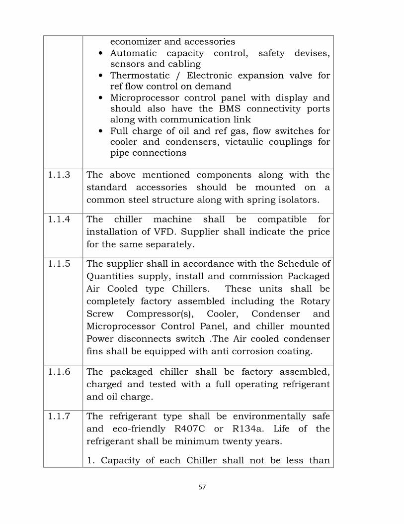
57
economizer and accessories
• Automatic capacity control, safety devises, sensors and cabling
• Thermostatic / Electronic expansion valve for ref flow control on demand
• Microprocessor control panel with display and should also have the BMS connectivity ports along with communication link
• Full charge of oil and ref gas, flow switches for cooler and condensers, victaulic couplings for pipe connections
1.1.3 The above mentioned components along with the
standard accessories should be mounted on a
common steel structure along with spring isolators.
1.1.4 The chiller machine shall be compatible for
installation of VFD. Supplier shall indicate the price
for the same separately.
1.1.5 The supplier shall in accordance with the Schedule of
Quantities supply, install and commission Packaged
Air Cooled type Chillers. These units shall be
completely factory assembled including the Rotary
Screw Compressor(s), Cooler, Condenser and
Microprocessor Control Panel, and chiller mounted
Power disconnects switch .The Air cooled condenser
fins shall be equipped with anti corrosion coating.
1.1.6 The packaged chiller shall be factory assembled,
charged and tested with a full operating refrigerant
and oil charge.
1.1.7 The refrigerant type shall be environmentally safe
and eco-friendly R407C or R134a. Life of the
refrigerant shall be minimum twenty years.
1. Capacity of each Chiller shall not be less than
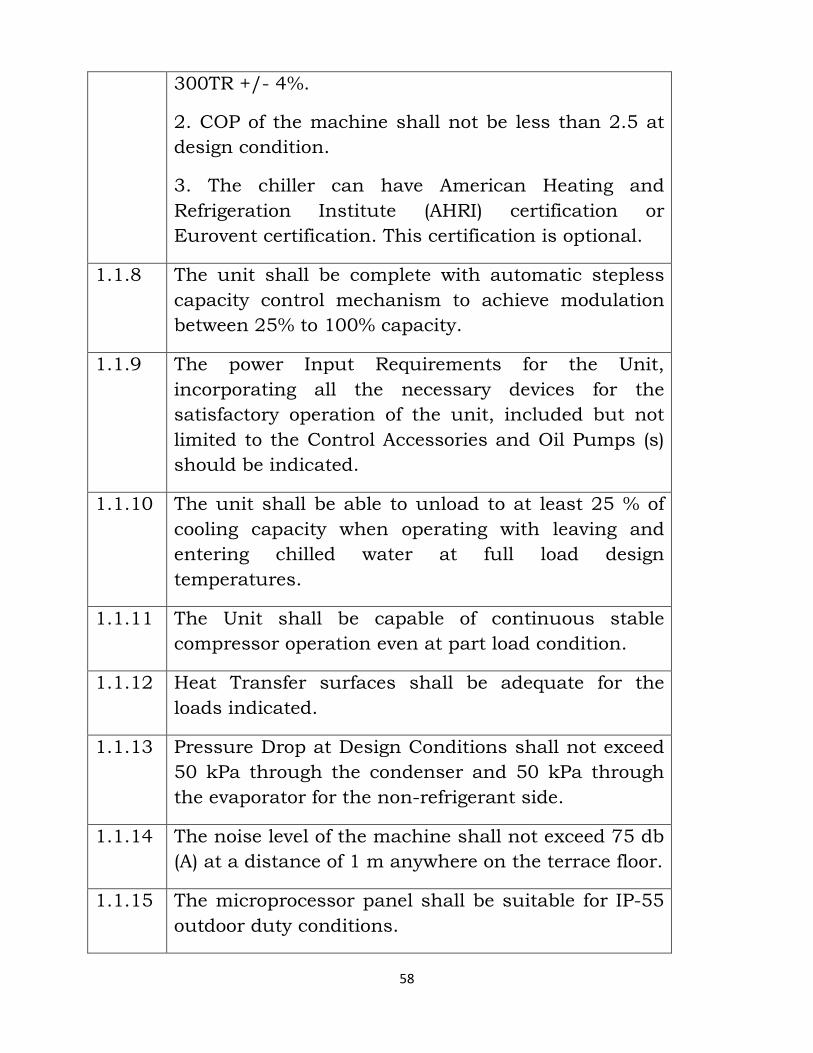
58
300TR +/- 4%.
2. COP of the machine shall not be less than 2.5 at
design condition.
3. The chiller can have American Heating and
Refrigeration Institute (AHRI) certification or
Eurovent certification. This certification is optional.
1.1.8 The unit shall be complete with automatic stepless
capacity control mechanism to achieve modulation
between 25% to 100% capacity.
1.1.9 The power Input Requirements for the Unit,
incorporating all the necessary devices for the
satisfactory operation of the unit, included but not
limited to the Control Accessories and Oil Pumps (s)
should be indicated.
1.1.10 The unit shall be able to unload to at least 25 % of
cooling capacity when operating with leaving and
entering chilled water at full load design
temperatures.
1.1.11 The Unit shall be capable of continuous stable
compressor operation even at part load condition.
1.1.12 Heat Transfer surfaces shall be adequate for the
loads indicated.
1.1.13 Pressure Drop at Design Conditions shall not exceed
50 kPa through the condenser and 50 kPa through
the evaporator for the non-refrigerant side.
1.1.14 The noise level of the machine shall not exceed 75 db
(A) at a distance of 1 m anywhere on the terrace floor.
1.1.15 The microprocessor panel shall be suitable for IP-55
outdoor duty conditions.
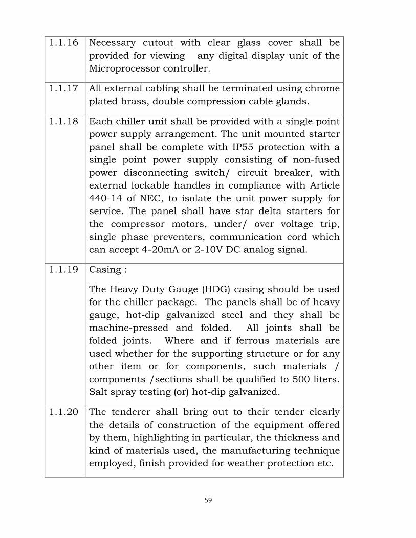
59
1.1.16 Necessary cutout with clear glass cover shall be
provided for viewing any digital display unit of the
Microprocessor controller.
1.1.17 All external cabling shall be terminated using chrome
plated brass, double compression cable glands.
1.1.18 Each chiller unit shall be provided with a single point
power supply arrangement. The unit mounted starter
panel shall be complete with IP55 protection with a
single point power supply consisting of non-fused
power disconnecting switch/ circuit breaker, with
external lockable handles in compliance with Article
440-14 of NEC, to isolate the unit power supply for
service. The panel shall have star delta starters for
the compressor motors, under/ over voltage trip,
single phase preventers, communication cord which
can accept 4-20mA or 2-10V DC analog signal.
1.1.19 Casing :
The Heavy Duty Gauge (HDG) casing should be used
for the chiller package. The panels shall be of heavy
gauge, hot-dip galvanized steel and they shall be
machine-pressed and folded. All joints shall be
folded joints. Where and if ferrous materials are
used whether for the supporting structure or for any
other item or for components, such materials /
components /sections shall be qualified to 500 liters.
Salt spray testing (or) hot-dip galvanized.
1.1.20 The tenderer shall bring out to their tender clearly
the details of construction of the equipment offered
by them, highlighting in particular, the thickness and
kind of materials used, the manufacturing technique
employed, finish provided for weather protection etc.
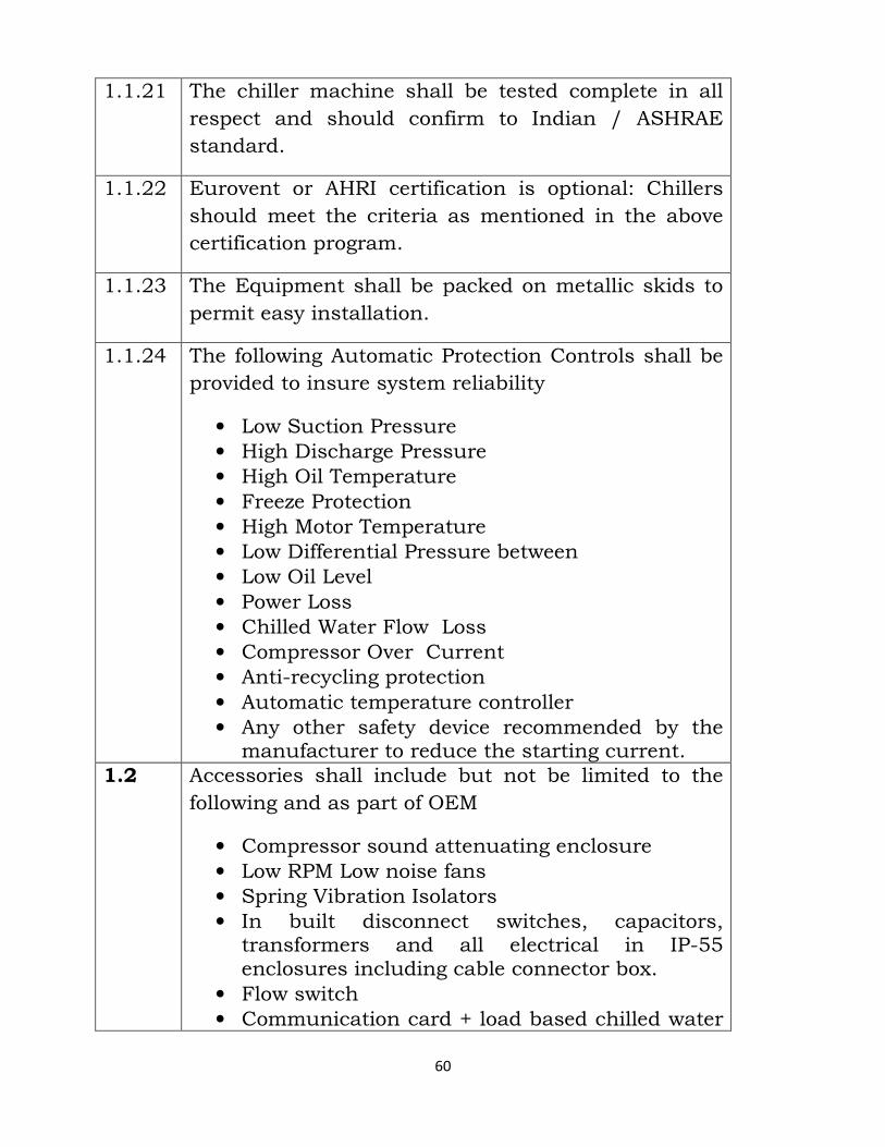
60
1.1.21 The chiller machine shall be tested complete in all
respect and should confirm to Indian / ASHRAE
standard.
1.1.22 Eurovent or AHRI certification is optional: Chillers
should meet the criteria as mentioned in the above
certification program.
1.1.23 The Equipment shall be packed on metallic skids to
permit easy installation.
1.1.24 The following Automatic Protection Controls shall be
provided to insure system reliability
• Low Suction Pressure • High Discharge Pressure • High Oil Temperature • Freeze Protection • High Motor Temperature • Low Differential Pressure between • Low Oil Level • Power Loss • Chilled Water Flow Loss • Compressor Over Current • Anti-recycling protection • Automatic temperature controller • Any other safety device recommended by the manufacturer to reduce the starting current.
1.2 Accessories shall include but not be limited to the
following and as part of OEM
• Compressor sound attenuating enclosure • Low RPM Low noise fans • Spring Vibration Isolators • In built disconnect switches, capacitors, transformers and all electrical in IP-55 enclosures including cable connector box.
• Flow switch • Communication card + load based chilled water
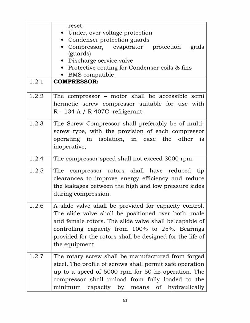
61
reset
• Under, over voltage protection • Condenser protection guards • Compressor, evaporator protection grids (guards)
• Discharge service valve • Protective coating for Condenser coils & fins • BMS compatible
1.2.1 COMPRESSOR:
1.2.2 The compressor – motor shall be accessible semi
hermetic screw compressor suitable for use with
R – 134 A / R-407C refrigerant.
1.2.3 The Screw Compressor shall preferably be of multi-
screw type, with the provision of each compressor
operating in isolation, in case the other is
inoperative,
1.2.4 The compressor speed shall not exceed 3000 rpm.
1.2.5 The compressor rotors shall have reduced tip
clearances to improve energy efficiency and reduce
the leakages between the high and low pressure sides
during compression.
1.2.6 A slide valve shall be provided for capacity control.
The slide valve shall be positioned over both, male
and female rotors. The slide valve shall be capable of
controlling capacity from 100% to 25%. Bearings
provided for the rotors shall be designed for the life of
the equipment.
1.2.7 The rotary screw shall be manufactured from forged
steel. The profile of screws shall permit safe operation
up to a speed of 5000 rpm for 50 hz operation. The
compressor shall unload from fully loaded to the
minimum capacity by means of hydraulically
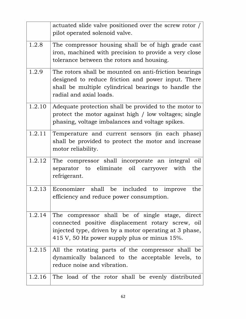
62
actuated slide valve positioned over the screw rotor /
pilot operated solenoid valve.
1.2.8 The compressor housing shall be of high grade cast
iron, machined with precision to provide a very close
tolerance between the rotors and housing.
1.2.9 The rotors shall be mounted on anti-friction bearings
designed to reduce friction and power input. There
shall be multiple cylindrical bearings to handle the
radial and axial loads.
1.2.10 Adequate protection shall be provided to the motor to
protect the motor against high / low voltages; single
phasing, voltage imbalances and voltage spikes.
1.2.11 Temperature and current sensors (in each phase)
shall be provided to protect the motor and increase
motor reliability.
1.2.12 The compressor shall incorporate an integral oil
separator to eliminate oil carryover with the
refrigerant.
1.2.13 Economizer shall be included to improve the
efficiency and reduce power consumption.
1.2.14 The compressor shall be of single stage, direct
connected positive displacement rotary screw, oil
injected type, driven by a motor operating at 3 phase,
415 V, 50 Hz power supply plus or minus 15%.
1.2.15 All the rotating parts of the compressor shall be
dynamically balanced to the acceptable levels, to
reduce noise and vibration.
1.2.16 The load of the rotor shall be evenly distributed
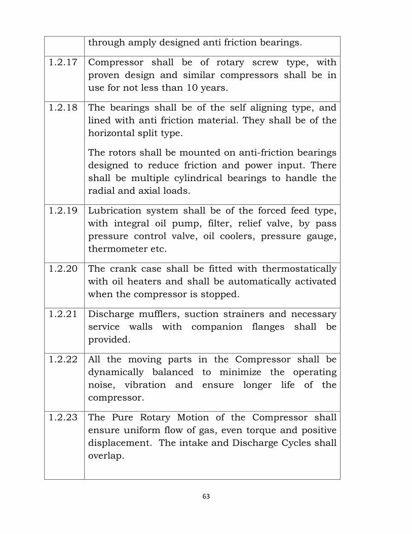
63
through amply designed anti friction bearings.
1.2.17 Compressor shall be of rotary screw type, with
proven design and similar compressors shall be in
use for not less than 10 years.
1.2.18 The bearings shall be of the self aligning type, and
lined with anti friction material. They shall be of the
horizontal split type.
The rotors shall be mounted on anti-friction bearings
designed to reduce friction and power input. There
shall be multiple cylindrical bearings to handle the
radial and axial loads.
1.2.19 Lubrication system shall be of the forced feed type,
with integral oil pump, filter, relief valve, by pass
pressure control valve, oil coolers, pressure gauge,
thermometer etc.
1.2.20 The crank case shall be fitted with thermostatically
with oil heaters and shall be automatically activated
when the compressor is stopped.
1.2.21 Discharge mufflers, suction strainers and necessary
service walls with companion flanges shall be
provided.
1.2.22 All the moving parts in the Compressor shall be
dynamically balanced to minimize the operating
noise, vibration and ensure longer life of the
compressor.
1.2.23 The Pure Rotary Motion of the Compressor shall
ensure uniform flow of gas, even torque and positive
displacement. The intake and Discharge Cycles shall
overlap.
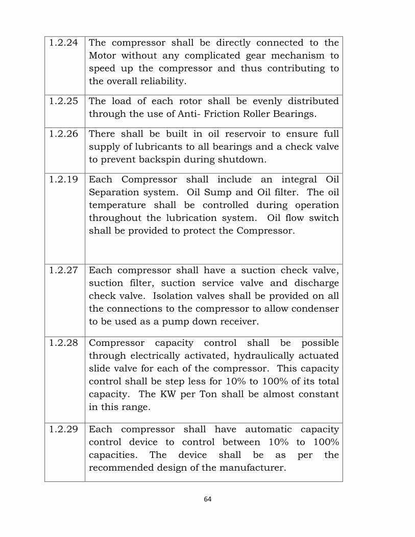
64
1.2.24 The compressor shall be directly connected to the
Motor without any complicated gear mechanism to
speed up the compressor and thus contributing to
the overall reliability.
1.2.25 The load of each rotor shall be evenly distributed
through the use of Anti- Friction Roller Bearings.
1.2.26 There shall be built in oil reservoir to ensure full
supply of lubricants to all bearings and a check valve
to prevent backspin during shutdown.
1.2.19 Each Compressor shall include an integral Oil
Separation system. Oil Sump and Oil filter. The oil
temperature shall be controlled during operation
throughout the lubrication system. Oil flow switch
shall be provided to protect the Compressor.
1.2.27 Each compressor shall have a suction check valve,
suction filter, suction service valve and discharge
check valve. Isolation valves shall be provided on all
the connections to the compressor to allow condenser
to be used as a pump down receiver.
1.2.28 Compressor capacity control shall be possible
through electrically activated, hydraulically actuated
slide valve for each of the compressor. This capacity
control shall be step less for 10% to 100% of its total
capacity. The KW per Ton shall be almost constant
in this range.
1.2.29 Each compressor shall have automatic capacity
control device to control between 10% to 100%
capacities. The device shall be as per the
recommended design of the manufacturer.
65
1.2.30 Devices for measuring the hours of operation shall be
incorporated.
1.3.0 MOTOR & STARTER :
1.3.1 The motor shall be of refrigerant cooled induction
type motor suitable for operation at 415V / 3Ø / 50
Hz power supply and should be able to withstand a
fluctuation of ± 15 %.
1.3.2 All the circuits should have independent circuits to
attend on maintenance.
1.3.3 The motor / compressor should be statically and
dynamically balanced for reducing vibration and
noise.
1.3.4 A removable sheet metal terminal box encloses the
terminal board area shall be provided.
1.3.5 The starter provided on the unit shall be such that it
will ensure starting current not to exceed 2.0 times
the rated current.
1.3.6 It shall also include all necessary safety devices i.e.,
overload relays, under voltage release, single phase
preventing device and phase unbalance or reversal.
They shall be provided with over current and under
current protection.
1.3.7 The motor windings shall have solid state protection
to prevent the motor from operating at unsafe
operating temperatures.
1.3.8 Hydrostatic, volumetric and refrigerant leak tests
shall be carried out at the manufacturer’s works
before the dispatch of the compressor.
1.3.9 The Supplier shall provide the Motor Electrical Data
66
and the Part Load Performance curves for the Chiller
being offered.
1.4.0 EVAPORATORS:
1.4.1 Evaporator shall be DX type/Flooded horizontal shell
and tube type. The shell is of carbon steel and the
tubes of copper. The shell shall be provided with
removable end plates. An adequate number of drain
points of ample size shall be provided to permit
draining and cleaning of the shell side. The
construction shall permit field removable of tubes for
maintenance.
1.4.2 Evaporator shall incorporate segmental baffles in the
shell to secure the desired fluid velocity, promote
turbulence and hereby achieve efficient heat transfer.
The refrigerant heads shall incorporate liquid inlet
and suction gas outlet connections, pass divisions,
equalizer and oil return connections.
1.4.3 Evaporator shall be suitable for use with
thermostatic / electronic expansion valves as
refrigerant feeding device. Provision shall be made for
fixing manually rest type antifreeze thermostat.
1.4.4 The end plates of the chiller shall be made of MS
thickness not less than 25 mm. The shell of the
chiller shall be made of MS of thickness not less than
8 mm with electric fusion welded seams.
1.4.5 The tubes shall be of seamless, hard drawn copper
with a minimum tube wall thickness of 0.71 mm for
plain tubes and minimum 0.63 at the root of fins.
67
The tubes shall be plain for DX type chillers and may
be either plain or internally finned for flooded type
chiller.
1.4.6 The tubes shall be rolled into grooves in the tube
sheets and flared in the ends. Intermediate tube
supports of steel or polypropylene shall be provided
at spacing not less than 1250 mm for flooded type
chiller and 500 mm for DX type chiller to prevent
sagging / vibration of tubes.
1.4.7 The flooded chillers shall have water boxes designed
for multi pass flow. The DX type chiller shall be
provided with adequate number of properly spaced
baffles so that the water passes through the tube
bundle many times.
1.4.8 The chiller shall be smooth finished with one coat of
zinc chromate primer before the insulation is applied.
1.4.9 The chiller shall be sand blasted from both inside
(before insertion of tubes) and outside.
1.4.10 Flexible bellows shall be provided both at inlets and
outlets of all chillers to minimize transmission of
vibration to connected piping system. The chiller
shall be insulated with nitrile rubber insulation
material of suitable thickness.
1.4.11 The chiller shall have the following accessories:
• Water drain valve. • Thermometers and pressure gauges. • Flow switches at the outlet. • Cooling thermostat and anti freeze thermostat. • Insulation as per the manufacturing standard.
1.4.12 The chiller shall be tested in the works to 1.5 times
the maximum working pressure for the refrigerant or
68
21 kg/sqcm whichever is higher. The water side of
the chiller shall also be tested to a hydraulic pressure
of 10 kg/sq.cm at the works. Test certificate shall be
produced.
1.4.13 Each refrigerant circuit of the chiller shall be able to
operate individually. The water velocity in the tubes
shall not exceed 2.5 m per second. The chiller shall
be based on a fouling factor of 0.0005 in FPS unit.
1.4.14 For DX type chiller: The DX type chiller shall be
provided with connections and accessories like
refrigerant inlet and outlet connections, TEV with
adjustable superheat control and external equalizer
part.
1.4.15 For Flooded type Chiller : The flooded type chiller
shall be provided connections and accessories like
refrigerant inlet and outlet connections, liquid
refrigerant float for level control/ expansion valve/
fixed or variable orifice, pressure relief device,
charging connection with valve, eliminator plate.
Drain and vent connection with valves, water inlet
and outlet connections, proper oil return system and
flow switch/ pressure switch/ differential flow
switch/ flow sensor in the water line.
1.5.0 AIR COOLED CONDENSERS:
1.5.1 The condenser coil shall be constructed of copper
tubes and die formed aluminium fins having self-
spacing collars. Fins shall be mechanically bonded
to the tubes. Coil shall be treated for corrosion free.
1.5.2 Refrigerant sub-cooling will be incorporated into the
coil. Baffles shall separate each condenser fan.
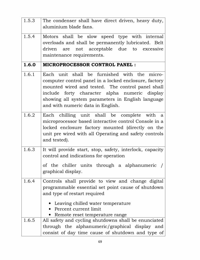
69
1.5.3 The condenser shall have direct driven, heavy duty,
aluminium blade fans.
1.5.4 Motors shall be slow speed type with internal
overloads and shall be permanently lubricated. Belt
driven are not acceptable due to excessive
maintenance requirements.
1.6.0 MICROPROCESSOR CONTROL PANEL :
1.6.1 Each unit shall be furnished with the micro-
computer control panel in a locked enclosure, factory
mounted wired and tested. The control panel shall
include forty character alpha numeric display
showing all system parameters in English language
and with numeric data in English.
1.6.2 Each chilling unit shall be complete with a
microprocessor based interactive control Console in a
locked enclosure factory mounted (directly on the
unit pre wired with all Operating and safety controls
and tested).
1.6.3 It will provide start, stop, safety, interlock, capacity
control and indications for operation
of the chiller units through a alphanumeric /
graphical display.
1.6.4 Controls shall provide to view and change digital
programmable essential set point cause of shutdown
and type of restart required
• Leaving chilled water temperature • Percent current limit • Remote reset temperature range
1.6.5 All safety and cycling shutdowns shall be enunciated
through the alphanumeric/graphical display and
consist of day time cause of shutdown and type of
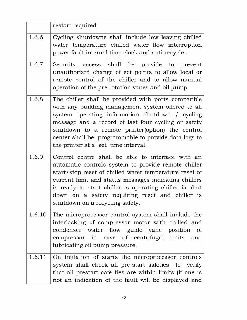
70
restart required
1.6.6 Cycling shutdowns shall include low leaving chilled
water temperature chilled water flow interruption
power fault internal time clock and anti-recycle .
1.6.7 Security access shall be provide to prevent
unauthorized change of set points to allow local or
remote control of the chiller and to allow manual
operation of the pre rotation vanes and oil pump
1.6.8 The chiller shall be provided with ports compatible
with any building management system offered to all
system operating information shutdown / cycling
message and a record of last four cycling or safety
shutdown to a remote printer(option) the control
center shall be programmable to provide data logs to
the printer at a set time interval.
1.6.9 Control centre shall be able to interface with an
automatic controls system to provide remote chiller
start/stop reset of chilled water temperature reset of
current limit and status messages indicating chillers
is ready to start chiller is operating chiller is shut
down on a safety requiring reset and chiller is
shutdown on a recycling safety.
1.6.10 The microprocessor control system shall include the
interlocking of compressor motor with chilled and
condenser water flow guide vane position of
compressor in case of centrifugal units and
lubricating oil pump pressure.
1.6.11 On initiation of starts the microprocessor controls
system shall check all pre-start safeties to verify
that all prestart cafe ties are within limits (if one is
not an indication of the fault will be displayed and
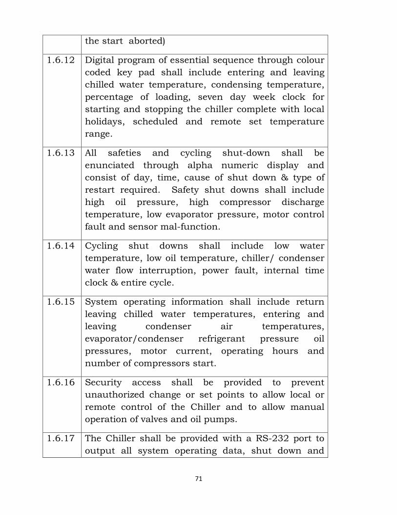
71
the start aborted)
1.6.12 Digital program of essential sequence through colour
coded key pad shall include entering and leaving
chilled water temperature, condensing temperature,
percentage of loading, seven day week clock for
starting and stopping the chiller complete with local
holidays, scheduled and remote set temperature
range.
1.6.13 All safeties and cycling shut-down shall be
enunciated through alpha numeric display and
consist of day, time, cause of shut down & type of
restart required. Safety shut downs shall include
high oil pressure, high compressor discharge
temperature, low evaporator pressure, motor control
fault and sensor mal-function.
1.6.14 Cycling shut downs shall include low water
temperature, low oil temperature, chiller/ condenser
water flow interruption, power fault, internal time
clock & entire cycle.
1.6.15 System operating information shall include return
leaving chilled water temperatures, entering and
leaving condenser air temperatures,
evaporator/condenser refrigerant pressure oil
pressures, motor current, operating hours and
number of compressors start.
1.6.16 Security access shall be provided to prevent
unauthorized change or set points to allow local or
remote control of the Chiller and to allow manual
operation of valves and oil pumps.
1.6.17 The Chiller shall be provided with a RS-232 port to
output all system operating data, shut down and
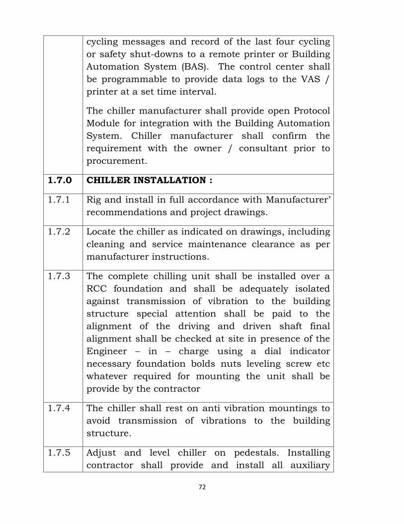
72
cycling messages and record of the last four cycling
or safety shut-downs to a remote printer or Building
Automation System (BAS). The control center shall
be programmable to provide data logs to the VAS /
printer at a set time interval.
The chiller manufacturer shall provide open Protocol
Module for integration with the Building Automation
System. Chiller manufacturer shall confirm the
requirement with the owner / consultant prior to
procurement.
1.7.0 CHILLER INSTALLATION :
1.7.1 Rig and install in full accordance with Manufacturer’
recommendations and project drawings.
1.7.2 Locate the chiller as indicated on drawings, including
cleaning and service maintenance clearance as per
manufacturer instructions.
1.7.3 The complete chilling unit shall be installed over a
RCC foundation and shall be adequately isolated
against transmission of vibration to the building
structure special attention shall be paid to the
alignment of the driving and driven shaft final
alignment shall be checked at site in presence of the
Engineer – in – charge using a dial indicator
necessary foundation bolds nuts leveling screw etc
whatever required for mounting the unit shall be
provide by the contractor
1.7.4 The chiller shall rest on anti vibration mountings to
avoid transmission of vibrations to the building
structure.
1.7.5 Adjust and level chiller on pedestals. Installing
contractor shall provide and install all auxiliary
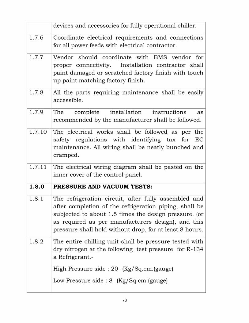
73
devices and accessories for fully operational chiller.
1.7.6 Coordinate electrical requirements and connections
for all power feeds with electrical contractor.
1.7.7 Vendor should coordinate with BMS vendor for
proper connectivity. Installation contractor shall
paint damaged or scratched factory finish with touch
up paint matching factory finish.
1.7.8 All the parts requiring maintenance shall be easily
accessible.
1.7.9 The complete installation instructions as
recommended by the manufacturer shall be followed.
1.7.10 The electrical works shall be followed as per the
safety regulations with identifying tax for EC
maintenance. All wiring shall be neatly bunched and
cramped.
1.7.11 The electrical wiring diagram shall be pasted on the
inner cover of the control panel.
1.8.0 PRESSURE AND VACUUM TESTS:
1.8.1 The refrigeration circuit, after fully assembled and
after completion of the refrigeration piping, shall be
subjected to about 1.5 times the design pressure. (or
as required as per manufacturers design), and this
pressure shall hold without drop, for at least 8 hours.
1.8.2 The entire chilling unit shall be pressure tested with
dry nitrogen at the following test pressure for R-134
a Refrigerant.-
High Pressure side : 20 -(Kg/Sq.cm.(gauge)
Low Pressure side : 8 -(Kg/Sq.cm.(gauge)
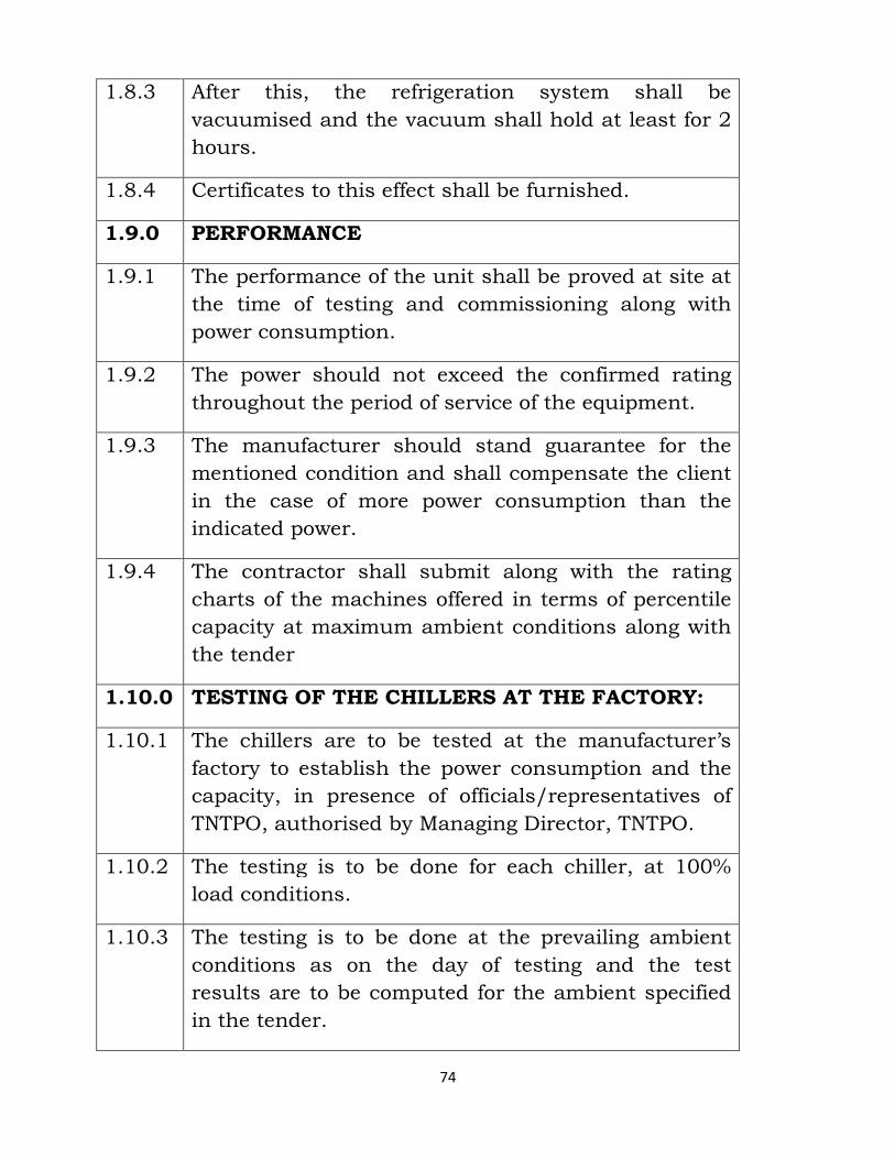
74
1.8.3 After this, the refrigeration system shall be
vacuumised and the vacuum shall hold at least for 2
hours.
1.8.4 Certificates to this effect shall be furnished.
1.9.0 PERFORMANCE
1.9.1 The performance of the unit shall be proved at site at
the time of testing and commissioning along with
power consumption.
1.9.2 The power should not exceed the confirmed rating
throughout the period of service of the equipment.
1.9.3 The manufacturer should stand guarantee for the
mentioned condition and shall compensate the client
in the case of more power consumption than the
indicated power.
1.9.4 The contractor shall submit along with the rating
charts of the machines offered in terms of percentile
capacity at maximum ambient conditions along with
the tender
1.10.0 TESTING OF THE CHILLERS AT THE FACTORY:
1.10.1 The chillers are to be tested at the manufacturer’s
factory to establish the power consumption and the
capacity, in presence of officials/representatives of
TNTPO, authorised by Managing Director, TNTPO.
1.10.2 The testing is to be done for each chiller, at 100%
load conditions.
1.10.3 The testing is to be done at the prevailing ambient
conditions as on the day of testing and the test
results are to be computed for the ambient specified
in the tender.
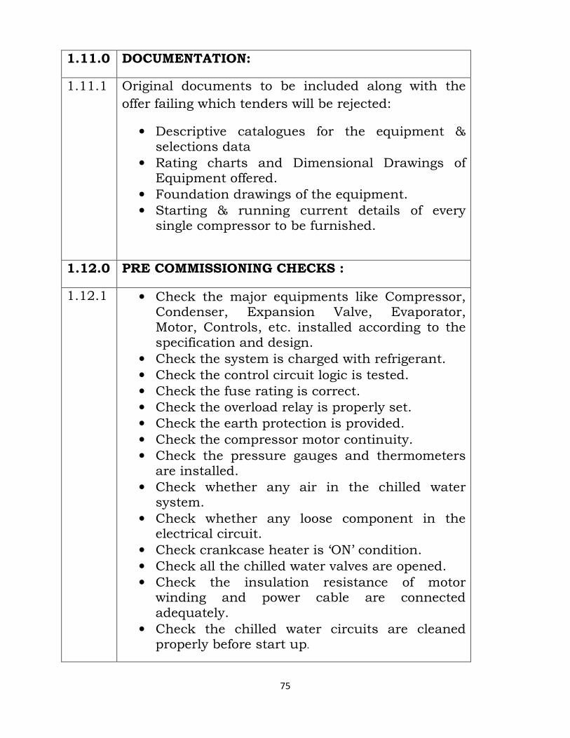
75
1.11.0 DOCUMENTATION:
1.11.1 Original documents to be included along with the
offer failing which tenders will be rejected:
• Descriptive catalogues for the equipment & selections data
• Rating charts and Dimensional Drawings of Equipment offered.
• Foundation drawings of the equipment. • Starting & running current details of every single compressor to be furnished.
1.12.0 PRE COMMISSIONING CHECKS :
1.12.1 • Check the major equipments like Compressor, Condenser, Expansion Valve, Evaporator, Motor, Controls, etc. installed according to the specification and design.
• Check the system is charged with refrigerant. • Check the control circuit logic is tested. • Check the fuse rating is correct. • Check the overload relay is properly set. • Check the earth protection is provided. • Check the compressor motor continuity. • Check the pressure gauges and thermometers are installed.
• Check whether any air in the chilled water system.
• Check whether any loose component in the electrical circuit.
• Check crankcase heater is ‘ON’ condition. • Check all the chilled water valves are opened. • Check the insulation resistance of motor winding and power cable are connected adequately.
• Check the chilled water circuits are cleaned properly before start up.
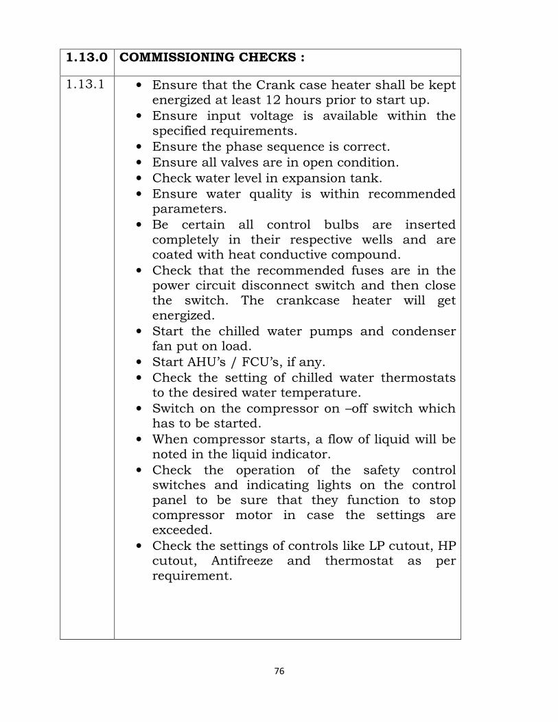
76
1.13.0 COMMISSIONING CHECKS :
1.13.1 • Ensure that the Crank case heater shall be kept energized at least 12 hours prior to start up.
• Ensure input voltage is available within the specified requirements.
• Ensure the phase sequence is correct. • Ensure all valves are in open condition. • Check water level in expansion tank. • Ensure water quality is within recommended parameters.
• Be certain all control bulbs are inserted completely in their respective wells and are coated with heat conductive compound.
• Check that the recommended fuses are in the power circuit disconnect switch and then close the switch. The crankcase heater will get energized.
• Start the chilled water pumps and condenser fan put on load.
• Start AHU’s / FCU’s, if any. • Check the setting of chilled water thermostats to the desired water temperature.
• Switch on the compressor on –off switch which has to be started.
• When compressor starts, a flow of liquid will be noted in the liquid indicator.
• Check the operation of the safety control switches and indicating lights on the control panel to be sure that they function to stop compressor motor in case the settings are exceeded.
• Check the settings of controls like LP cutout, HP cutout, Antifreeze and thermostat as per requirement.
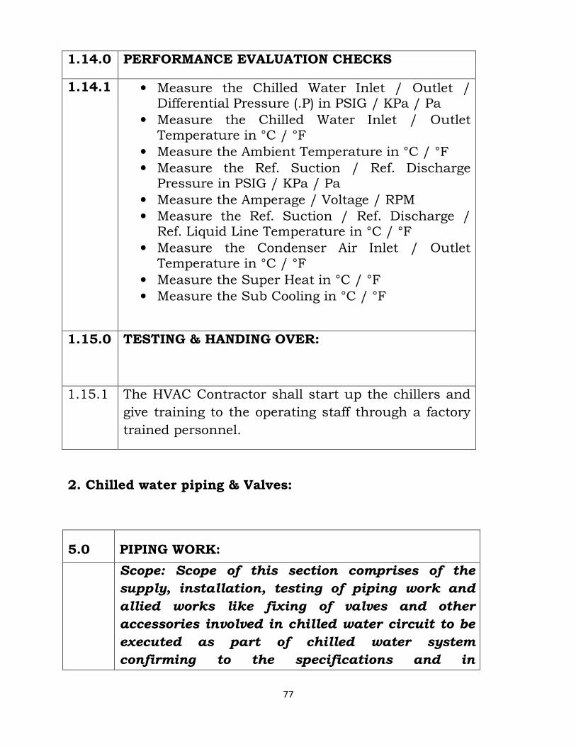
77
1.14.0 PERFORMANCE EVALUATION CHECKS
1.14.1 • Measure the Chilled Water Inlet / Outlet / Differential Pressure (.P) in PSIG / KPa / Pa
• Measure the Chilled Water Inlet / Outlet Temperature in °C / °F
• Measure the Ambient Temperature in °C / °F • Measure the Ref. Suction / Ref. Discharge Pressure in PSIG / KPa / Pa
• Measure the Amperage / Voltage / RPM • Measure the Ref. Suction / Ref. Discharge / Ref. Liquid Line Temperature in °C / °F
• Measure the Condenser Air Inlet / Outlet Temperature in °C / °F
• Measure the Super Heat in °C / °F • Measure the Sub Cooling in °C / °F
1.15.0
TESTING & HANDING OVER:
1.15.1
The HVAC Contractor shall start up the chillers and
give training to the operating staff through a factory
trained personnel.
2. Chilled water piping & Valves:
5.0 PIPING WORK:
Scope: Scope of this section comprises of the
supply, installation, testing of piping work and
allied works like fixing of valves and other
accessories involved in chilled water circuit to be
executed as part of chilled water system
confirming to the specifications and in
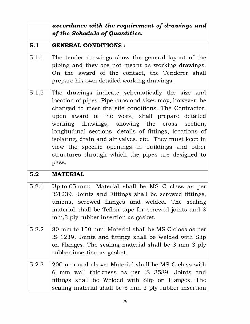
78
accordance with the requirement of drawings and
of the Schedule of Quantities.
5.1 GENERAL CONDITIONS :
5.1.1 The tender drawings show the general layout of the
piping and they are not meant as working drawings.
On the award of the contact, the Tenderer shall
prepare his own detailed working drawings.
5.1.2 The drawings indicate schematically the size and
location of pipes. Pipe runs and sizes may, however, be
changed to meet the site conditions. The Contractor,
upon award of the work, shall prepare detailed
working drawings, showing the cross section,
longitudinal sections, details of fittings, locations of
isolating, drain and air valves, etc. They must keep in
view the specific openings in buildings and other
structures through which the pipes are designed to
pass.
5.2 MATERIAL
5.2.1 Up to 65 mm: Material shall be MS C class as per
IS1239. Joints and Fittings shall be screwed fittings,
unions, screwed flanges and welded. The sealing
material shall be Teflon tape for screwed joints and 3
mm,3 ply rubber insertion as gasket.
5.2.2 80 mm to 150 mm: Material shall be MS C class as per
IS 1239. Joints and fittings shall be Welded with Slip
on Flanges. The sealing material shall be 3 mm 3 ply
rubber insertion as gasket.
5.2.3 200 mm and above: Material shall be MS C class with
6 mm wall thickness as per IS 3589. Joints and
fittings shall be Welded with Slip on Flanges. The
sealing material shall be 3 mm 3 ply rubber insertion
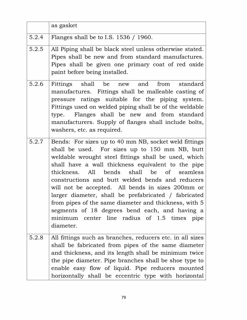
79
as gasket
5.2.4 Flanges shall be to I.S. 1536 / 1960.
5.2.5 All Piping shall be black steel unless otherwise stated.
Pipes shall be new and from standard manufactures.
Pipes shall be given one primary coat of red oxide
paint before being installed.
5.2.6 Fittings shall be new and from standard
manufactures. Fittings shall be malleable casting of
pressure ratings suitable for the piping system.
Fittings used on welded piping shall be of the weldable
type. Flanges shall be new and from standard
manufacturers. Supply of flanges shall include bolts,
washers, etc. as required.
5.2.7 Bends: For sizes up to 40 mm NB, socket weld fittings
shall be used. For sizes up to 150 mm NB, butt
weldable wrought steel fittings shall be used, which
shall have a wall thickness equivalent to the pipe
thickness. All bends shall be of seamless
constructions and butt welded bends and reducers
will not be accepted. All bends in sizes 200mm or
larger diameter, shall be prefabricated / fabricated
from pipes of the same diameter and thickness, with 5
segments of 18 degrees bend each, and having a
minimum center line radius of 1.5 times pipe
diameter.
5.2.8 All fittings such as branches, reducers etc. in all sizes
shall be fabricated from pipes of the same diameter
and thickness, and its length shall be minimum twice
the pipe diameter. Pipe branches shall be shoe type to
enable easy flow of liquid. Pipe reducers mounted
horizontally shall be eccentric type with horizontal
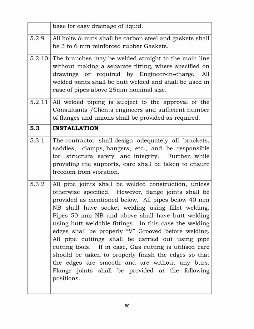
80
base for easy drainage of liquid.
5.2.9 All bolts & nuts shall be carbon steel and gaskets shall
be 3 to 6 mm reinforced rubber Gaskets.
5.2.10 The branches may be welded straight to the main line
without making a separate fitting, where specified on
drawings or required by Engineer-in-charge. All
welded joints shall be butt welded and shall be used in
case of pipes above 25mm nominal size.
5.2.11 All welded piping is subject to the approval of the
Consultants /Clients engineers and sufficient number
of flanges and unions shall be provided as required.
5.3 INSTALLATION
5.3.1 The contractor shall design adequately all brackets,
saddles, clamps, hangers, etc., and be responsible
for structural safety and integrity. Further, while
providing the supports, care shall be taken to ensure
freedom from vibration.
5.3.2 All pipe joints shall be welded construction, unless
otherwise specified. However, flange joints shall be
provided as mentioned below. All pipes below 40 mm
NB shall have socket welding using fillet welding.
Pipes 50 mm NB and above shall have butt welding
using butt weldable fittings. In this case the welding
edges shall be properly “V” Grooved before welding.
All pipe cuttings shall be carried out using pipe
cutting tools. If in case, Gas cutting is utilised care
should be taken to properly finish the edges so that
the edges are smooth and are without any burs.
Flange joints shall be provided at the following
positions.
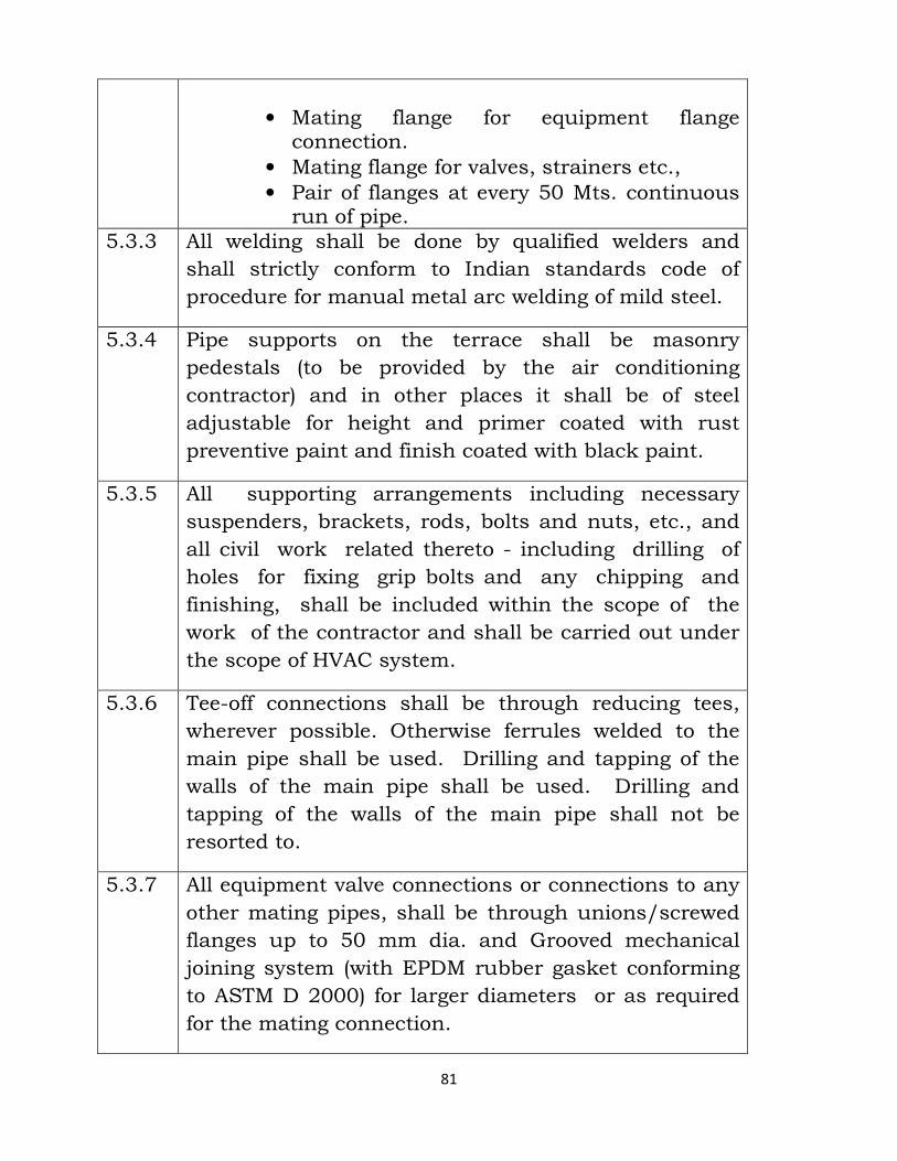
81
• Mating flange for equipment flange connection.
• Mating flange for valves, strainers etc., • Pair of flanges at every 50 Mts. continuous run of pipe.
5.3.3 All welding shall be done by qualified welders and
shall strictly conform to Indian standards code of
procedure for manual metal arc welding of mild steel.
5.3.4 Pipe supports on the terrace shall be masonry
pedestals (to be provided by the air conditioning
contractor) and in other places it shall be of steel
adjustable for height and primer coated with rust
preventive paint and finish coated with black paint.
5.3.5 All supporting arrangements including necessary
suspenders, brackets, rods, bolts and nuts, etc., and
all civil work related thereto - including drilling of
holes for fixing grip bolts and any chipping and
finishing, shall be included within the scope of the
work of the contractor and shall be carried out under
the scope of HVAC system.
5.3.6 Tee-off connections shall be through reducing tees,
wherever possible. Otherwise ferrules welded to the
main pipe shall be used. Drilling and tapping of the
walls of the main pipe shall be used. Drilling and
tapping of the walls of the main pipe shall not be
resorted to.
5.3.7 All equipment valve connections or connections to any
other mating pipes, shall be through unions/screwed
flanges up to 50 mm dia. and Grooved mechanical
joining system (with EPDM rubber gasket conforming
to ASTM D 2000) for larger diameters or as required
for the mating connection.
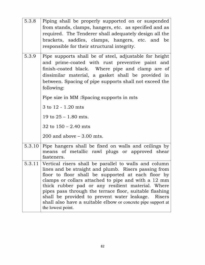
82
5.3.8 Piping shall be properly supported on or suspended
from stands, clamps, hangers, etc. as specified and as
required. The Tenderer shall adequately design all the
brackets, saddles, clamps, hangers, etc. and be
responsible for their structural integrity.
5.3.9 Pipe supports shall be of steel, adjustable for height
and prime-coated with rust preventive paint and
finish-coated black. Where pipe and clamp are of
dissimilar material, a gasket shall be provided in
between. Spacing of pipe supports shall not exceed the
following:
Pipe size in MM :Spacing supports in mts
3 to 12 - 1.20 mts
19 to 25 – 1.80 mts.
32 to 150 – 2.40 mts
200 and above – 3.00 mts.
5.3.10 Pipe hangers shall be fixed on walls and ceilings by means of metallic rawl plugs or approved shear fasteners.
5.3.11 Vertical risers shall be parallel to walls and column lines and be straight and plumb. Risers passing from floor to floor shall be supported at each floor by clamps or collars attached to pipe and with a 12 mm thick rubber pad or any resilient material. Where pipes pass through the terrace floor, suitable flashing shall be provided to prevent water leakage. Risers shall also have a suitable elbow or concrete pipe support at
the lowest point.
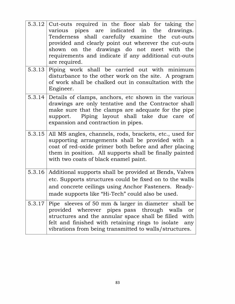
83
5.3.12 Cut-outs required in the floor slab for taking the various pipes are indicated in the drawings. Tenderness shall carefully examine the cut-outs provided and clearly point out wherever the cut-outs shown on the drawings do not meet with the requirements and indicate if any additional cut-outs are required.
5.3.13 Piping work shall be carried out with minimum disturbance to the other work on the site. A program of work shall be chalked out in consultation with the Engineer.
5.3.14 Details of clamps, anchors, etc shown in the various drawings are only tentative and the Contractor shall make sure that the clamps are adequate for the pipe support. Piping layout shall take due care of expansion and contraction in pipes.
5.3.15 All MS angles, channels, rods, brackets, etc., used for supporting arrangements shall be provided with a coat of red-oxide primer both before and after placing them in position. All supports shall be finally painted with two coats of black enamel paint.
5.3.16 Additional supports shall be provided at Bends, Valves
etc. Supports structures could be fixed on to the walls
and concrete ceilings using Anchor Fasteners. Ready-
made supports like “Hi-Tech” could also be used.
5.3.17 Pipe sleeves of 50 mm & larger in diameter shall be provided wherever pipes pass through walls or structures and the annular space shall be filled with felt and finished with retaining rings to isolate any vibrations from being transmitted to walls/structures.
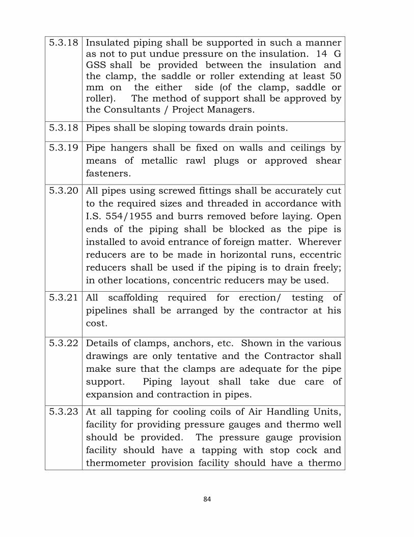
84
5.3.18 Insulated piping shall be supported in such a manner as not to put undue pressure on the insulation. 14 G GSS shall be provided between the insulation and the clamp, the saddle or roller extending at least 50 mm on the either side (of the clamp, saddle or roller). The method of support shall be approved by the Consultants / Project Managers.
5.3.18 Pipes shall be sloping towards drain points.
5.3.19 Pipe hangers shall be fixed on walls and ceilings by
means of metallic rawl plugs or approved shear
fasteners.
5.3.20 All pipes using screwed fittings shall be accurately cut
to the required sizes and threaded in accordance with
I.S. 554/1955 and burrs removed before laying. Open
ends of the piping shall be blocked as the pipe is
installed to avoid entrance of foreign matter. Wherever
reducers are to be made in horizontal runs, eccentric
reducers shall be used if the piping is to drain freely;
in other locations, concentric reducers may be used.
5.3.21 All scaffolding required for erection/ testing of
pipelines shall be arranged by the contractor at his
cost.
5.3.22 Details of clamps, anchors, etc. Shown in the various
drawings are only tentative and the Contractor shall
make sure that the clamps are adequate for the pipe
support. Piping layout shall take due care of
expansion and contraction in pipes.
5.3.23 At all tapping for cooling coils of Air Handling Units,
facility for providing pressure gauges and thermo well
should be provided. The pressure gauge provision
facility should have a tapping with stop cock and
thermometer provision facility should have a thermo
85
well.
5.3.24 GI Pipes whenever welded, the welded portions should
be immediately finished by painting the same with
zinc chromate primer.
5.3.25 When pipes are buried underground, both insulated
and un-insulated pipes shall be painted with one coat
of hot bitumen 80/25 at 2.5 Kg/sqm and wrapped
with 6 mm thick Tar felt and the joints properly glued.
5.3.26 All pipes using screwed fittings shall be accurately cut
to the required sizes and threaded in accordance with
I.S. 554/1955 and burrs removed before laying. Open
ends of the piping shall be blocked as the pipe is
installed to avoid entrance of foreign matter. Wherever
reducers are to be made in horizontal runs, eccentric
reducers shall be used if the piping is to drain freely;
in other locations, concentric reducers may be used.
5.3.27 All pipes shall be laid and tack welded in position with
all flanges, valves, etc., After inspection and approval
of the layout by the Engineer in-charge, only then full
welding could be carried out. Please note, to reduce
down time, pipes could be offered for inspection in
sections.
5.3.28 Further, when the piping is completely over the
Contractor should flush the entire piping at least three
times before commissioning, so that, the piping
system is free from dirt, mill scale etc.,
5.4 DRAIN PIPING
5.4.1 Drains shall be provided at all low points in the piping
in the piping system and shall be of the following
sizes.
86
Up to 200 mm - 40 mm
Over 200 mm - 50 mm
5.4.2 Drains shall be provided with ball valves of equal size.
Drains shall be piped through equal size G.I. pipe or
pvc pipe as specified to the nearest drain or floor
waste. Piping shall be pitched towards drain points.
5.4.3 All drain pipes shall be installed pitched @ 2% towards
the drain points. Only GI or PVC Pipes shall be used
for drain piping.
5.5 TESTING:
5.5.1 Pipes after full welding is completed shall be
hydraulically tested, without giving connections to the
equipment. Pipes could be tested in sections and after
testing the ends should be capped.
5.5.2 All piping shall be tested to a hydrostatic test pressure of at least one and half times the maximum operating pressure, but not less than 10 Kg/sqcm for a period of not less than 24 hours. All leaks and defects in joints revealed during the testing shall be rectified to the satisfaction of the Owners / PMC . Piping repaired subsequent to the above pressure test shall be re-tested in the same manner.
5.5.3 The Contractor shall provide all materials, tools,
equipment, instruments, services and labour
required to perform the test and to remove water
resulting from cleaning and / after testing.
5.5.4 Systems may be tested in sections and such sections
shall be securely capped.
5.5.5 The Owners / PMC shall be notified well in advance
by the Contractor of his intention to test a section or
87
sections of piping and all testing shall be witnessed by
the Owners / PMC or their authorised representatives.
5.5.6 The Contractor shall make sure that proper noiseless
circulation of fluid is achieved through all coils and
other heat exchange equipment in the system
concerned. If proper circulation is not achieved due to
air bound connections, the Contractor shall rectify the
defective connections. He shall bear all the expenses
for carrying out the above rectification’s, including the
tearing up and re-finishing or floors, walls, etc. as
required.
5.5.7 The contractor shall make sure that proper noiseless
circulation of fluid is achieved through all coils and
other heat exchange equipment in the system
concerned. In case of improper circulation, the
contractor shall rectify the defective connections. He
shall bear all expenses for carrying out the above
rectifications. He shall bear all expenses for Carrying
out above rectifications, including the tearing up and
re-finishing of floors and walls as required.
5.5.8 No insulation or painting for the pipes shall be carried
out before the hydraulic testing is completed and
approved by their Engineer in-charge.
5.5.9 After completion of Pressure testing the entire water
should be drained off by the Contractor without
affecting the premises.
VALVES :
5.6 BUTTERFLY VALVES :
5.6.1 Butterfly valve should be designed and manufactured
to have optimal mixed of structural stability, flow
efficiency and effective seating coupled with advantage
88
of light weight and compact design and ease of
operation.
5.6.2 Butterfly valves shall be of slim seal, short wafer type
with standard finish.
5.6.3 The valves shall be suitable for mounting between
flanges drilled to ANSI 125. The valve body shall be
cast iron. The disc shall consist of disc pivot and
driving stem. The disc shall move in bearings on both
ends with ‘O’ Ring to prevent leakage. The seat shall
be moulded black nitrile rubber or nylon.
5.6.4 The valves shall be of PN 10 rating shall be complete
with flow control lever and notches, factory machined
companion flanges, bolts & nuts. The valves shall
have extended stem for proper finishing of insulation.
5.6.5 All valves for sizes 50 mm and above shall be wafer
type butterfly valves. The valves should be suitable for
mounting between flanges drilled to IS 6392 Table 10
to 20. The valve body shall be cast iron. The valve
stem shall be high tensile stainless steel (AISI 410).
5.6.6 Body liner shall be integrally molded and bonded to
the body. The material shall be Buna-N Rubber. This
body liner shall provide seating to the valve disk and
“Gasket Joint” with mating pipe flanges. The valve
disk material shall be Ductile (SG) Iron with
Electroless Nickel Coating.
5.6.7 All valves up to 200 mm NB shall be provided with
flow control levers. Valves of 250 mm NB and above
shall be provided with gear operated levers.
5.6.8 The valve shall be flanged type design and shall be
suitable for water flow in either direction and seal in
both the directions. These should be suitable for tight
89
shut off or regulating flow.
5.6.9 Valve design should be such that Electrical Actuator
can also use as operator.
5.6.10 Construction: Body shall be made of one piece design
and top flange is design such to mount required valve
operator. Body material shall be Grey Cast Iron to IS
210 Gr. FG 220/ASTM A126 Gr. B/BS 1452 Gr. 220.
The Disc shall be of SG Iron to IS 1865Gr. 450/10
Teflon / Nickel plating /Nylon coating. The shaft shall
be of stainless steel ( AISI 410 ).
5.6.11 Valve Operators: Valve size from 50 mm (2”) to 200
mm (8”) N.B shall be self locking lever operation from
open to fully close position with 6 to 8 intermediate
position marked on the indicator plate which should
be mounted on the top flange. Valve size above 250
mm ( 10” ) N.B and above should be provided with
international class two piece sheet metal fully sealed
and weather proof Gear Operated for low torque and
smooth operation.
5.7 BALL VALVES :
5.7.1 All valves for shut-off purposes for sizes below 50 mm
shall be ball valves. The valve body and body
connector shall be carbon steel as per ASTM A216-
WCB, the ball and stem shall be stainless steel SS
304/316.
5.7.2 The seats and stem packing shall be PTFE. All Valves
shall have socket weldable ends, in 2/3 piece
construction and the central portion could be bolted
out for maintenance. All valves should be supplied in
full bore construction. The valves should have a
90
pressure rating of ANSI 150.
5.7.3 Valve should be design such, with quarter turn of
valve should be fully opened or closed position. Arrow
should be marked on the body to show flow direction.
Maximum working pressure should be 500 PSIG (35
kg/sq.cm ) and operating temperature range -40°F to
300°F.
5.8 BALANCING VALVES:
5.8.1 Balancing Valves: Wherever indicated in the pipe
scheme diagrams balancing valves shall be installed
for flow regulating and measuring purposes. Valve up
to 50 mm dia shall be bronze construction and valves
65 mm and above shall be cast iron construction.
5.8.2 All valves shall be provided with tapping for pressure
drop measurements.
5.8.3 Balancing valves shall be supplied and installed as
shown in the drawings to ensure proper balancing of
water. The balancing valves shall be fully automatic.
These shall have spring loaded catridge. Balancing
valve shall be of PN 16 rating.
5.8.4 The port opening shall permit precise regulation of
flow rate, by accurately measuring the pressure drop
across the port.
5.8.5 The spindle shall have a shielded screw to set the flow
at the desired level.
5.8.6 The valve shall be completed with two ports for
connections to a mercury manometer, to measure the
pressure drop, as well as a drain port.
91
5.9 CHECK VALVES :
5.9.1 Check Valves shall be dual plate check valves, wafer
type sleep-on construction. The valve body shall be
cast iron as per IS 210 Gr. FG 220. The valve disk
shall be aluminum - bronze plate, SS 316 inch pins &
pins and springs rubber seal and should be rated for a
pressure rating of ANSI 150.
5.9.2 The valves shall be heavy class and provided as
shown in the applicable drawings (and /or in BOQ)
and conform to the following specifications:
The valves shall have spring loaded, light weight plates
enabling them to be operated in any position (vertical
or Horizontal). The valves shall be provided with
resilient seal material to ensure sealing without leak.
5.9.3 The valves shall be suitable for operation at pressures
up to 13.8 Kg/Cm2 (200 psig).
5.10 SUCTION GUIDE :
5.10.1 Suction Guide shall be installed at the inlet of each
pump. Suction Guide shall have cast iron body, outlet
guide vanes, removable stainless steel strainer and
fine mesh brass start-up filter.
5.10.2 The Contractor shall inspect the strainer prior to start-
up of the pump and shall remove the fine mesh brass
filter after short running period. Space shall be
provided for removal of strainer and for connection of
blow down valve.
5.11 STRAINERS :
5.11.1 Strainers shall be of the approved “Y” or with
fabricated steel bodies, mounting supports, bottom
92
drain valve.
5.11.2 Strainers shall have a removable stainless steel–304
screen with 3mm perforations and permanent magnet.
Strainers shall be provided with flanges or threaded
sockets as required.
5.11.3 They shall be designed to enable blowing out
accumulated dirt and facilitate removal and
replacement of all screens without disconnecting the
main pipe.
5.11.4 All strainers shall be provided with equal size isolating
butterfly valves, as mentioned in quantities, so that
the strainer may be cleaned without draining the
system.
5.11.5 “Y” strainers shall be provided on the inlet side of each
air handling unit.
5.12 TWO WAY VALVES :
5.12.1 The 2 way mixing/diverting valves for AHUs shall be of
C.I. constructions suitable for operation up to 10 bar.
The water flow through the valve shall be regulated by
the rotation of brass slipper between the main and the
bypass ports.
5.12.2 It shall be possible to rotate the brass slipper,
manually, through 360° and interchange the main and
the common ports, to facilitate installation at site. All
internals of the valves shall be rust-proof and the `O'
rings shall be of EPDM/NITRILE.
5.12.3 All valves shall be designed for a body pressure of 10
Kg/sqcm. The flow characteristics shall be linear for
each port. The valves shall be compatible to hook up
with direct digital control systems.
93
5.12.4 These valves shall be provided for air handling units
installed in chilled water lines at each AHU. A
proportional thermostat shall actuate each valve.
5.12.5 Constant space conditions shall be maintained by
allowing correct quantity of chilled water to pass
through the coil. Valves shall have cast bronze body
up to 40 mm and CI body for higher sizes.
5.12.6 Modulating motors used with valve linkages shall
actuate valves. Modulating motors and linkages
should be selected after ascertaining the torque
requirements of the valves.
5.12.7 The valve actuator shall be electronic type with DC
motor. The actuator's angle of rotation shall be 90° . It
shall be without any limit switches and shall be
overload proof. It shall have an indicator to indicate
the position and push-button to disengage the gear
train for manual operation.
5.13 AUTOMATIC AIR VENTS :
5.13.1 The Auto Air Vent shall be installed on all high points
in the water piping system and also at locations where
there is a likelihood of air locking , to automatically
remove the trapped air.
5.13.2 It should be of compact & efficient design made of
Brass construction to efficiently remove air pockets
from hydraulic systems with a maximum working
pressure of 4-6 bar & working temperature of 120 deg
C. Automatic air vents shall be provided at highest
points as shown in the approved drawings.
5.13.3 All air vent valves should have a hose nipple fixed at
the open end, so that a flexible hose could be fixed to
94
drain-off during purging.
5.13.4 The Vent valve sizes shall be as under:
Pipe Size up to 150 NB : 12 mm NB Ball Valve with
hose nipple.
Pipe size above 150 NB : 20mm NB Ball Valve with
hose nipple.
5.13.5 The body shall be of brass construction and a plastic
cap shall be provided on the outlet to shut the air vent
when not in use.
5.13.6 The float shall be of synthetic material and shall keep
the venting valve closed under normal condition .
When air is collected inside the float chamber, the
water level inside the auto air vent shall decrease and
the venting valve shall be opened.
5.13.7 The collected air then shall escape through the venting
valve and the water level inside the float chamber shall
increase again, closing the venting valve. This process
shall continue as long as air is collected in the float
chamber.
5.13.8 There shall be a check valve at the bottom to seal the
system when the auto air vent is removed for servicing.
5.14 TEST POINT :
5.14.1 A Test Point shall be installed at the inlet and outlet of
each pump, balancing valve and heat exchange
equipment like Chiller, Condenser, Cooling Tower,
Water Cooling Coil, boiler. Test Points shall also be
provided at different locations in the water pipe line to
facilitate pressure measurement.
5.14.2 Test Point shall be of brass construction, 1/4" BSP
95
with NEOPRENE sealing bushes and shall be provided
with screwed cover.
5.15 PRESSURE GUAGES:
5.15.1 Pressure Gauges shall be “Bourdon” type with a
minimum dial size of 100 mm dia. The range shall be
selected to suit the application and location of the
gauges.
5.15.2 All gauges shall be provided with a gun metal plug
type gauge cock and capillary connections to prevent
system fluctuations.
5.15.3 They shall be selected for appropriate range and shall
be complete with gate or ball valve. Pressure gauges
shall be provided as shown in the drawings & as per
price schedule.
5.15.4 Pressure gauge tapping shall be insulated with 9 mm
nitrile foam insulation and tied with binding wire or
self adhesive tape. Chilled water pipe insulation shall
not be damaged during removal and re-fixing of
pressure gauge.
5.15.5 Water Pressure Gauge of 100 mm dia made out of
stainless steel SS-304 with a latest technology, all
parts are made from copper alloy & Stainless Steel to
prevent from corrosion attack.
5.15.6 Dial is in white color and numbers are in black color
with base of white color for better visibility, Gauge
shall have a Stainless Steel ‘U’ Tube of 15 mm dia x
400 mm in length both side threaded with Stainless
Steel Nut, a Ball Valve is also provided at one end of
tube for protecting gauge during testing of system.
5.15.7 Pressure gauges shall be installed on suction and
96
discharge sides of pumps, chilled water supply and
return at air handling units, inlet and outlet at chillers
and condensers, as shown on the Drawings and
included in Schedule of Quantities.
5.15.8 Discharge side gauges at pumps and at all other
locations shall be 150 mm dia range 0-10 Kg. per
Sq.cm (0-150 psi) pressure.
5.15.9 Care shall be taken to protect pressure gauges during
pressure testing.
5.15.1
0
Gauges shall be duly calibrated before installation.
The siphon and pet cock shall be of Brass chromium
plated.
5.16 THERMOMETERS :
5.16.1 Thermometers with extended sensing probe, thermo
well made out of copper / brass and glycerin should
be used for sensing temperature in thermo well.
5.16.2 These shall not be less than 100 mm dia. They shall
be selected for appropriate range and shall be with the
protection guard and mounting box. Protection guard
and mounting box shall be powder coated.
5.17 MEASUREMENTS :
5.17.1 Piping shall be measured along the centre line if
installed pipes including all pipe fittings and
accessories but excluding valves and other items for
which quantities are specifically indicated in the
schedule of work. No separate payment shall be made
for fittings and accessories.
5.17.2 The pipe lengths specified in the BOQ shall deemed
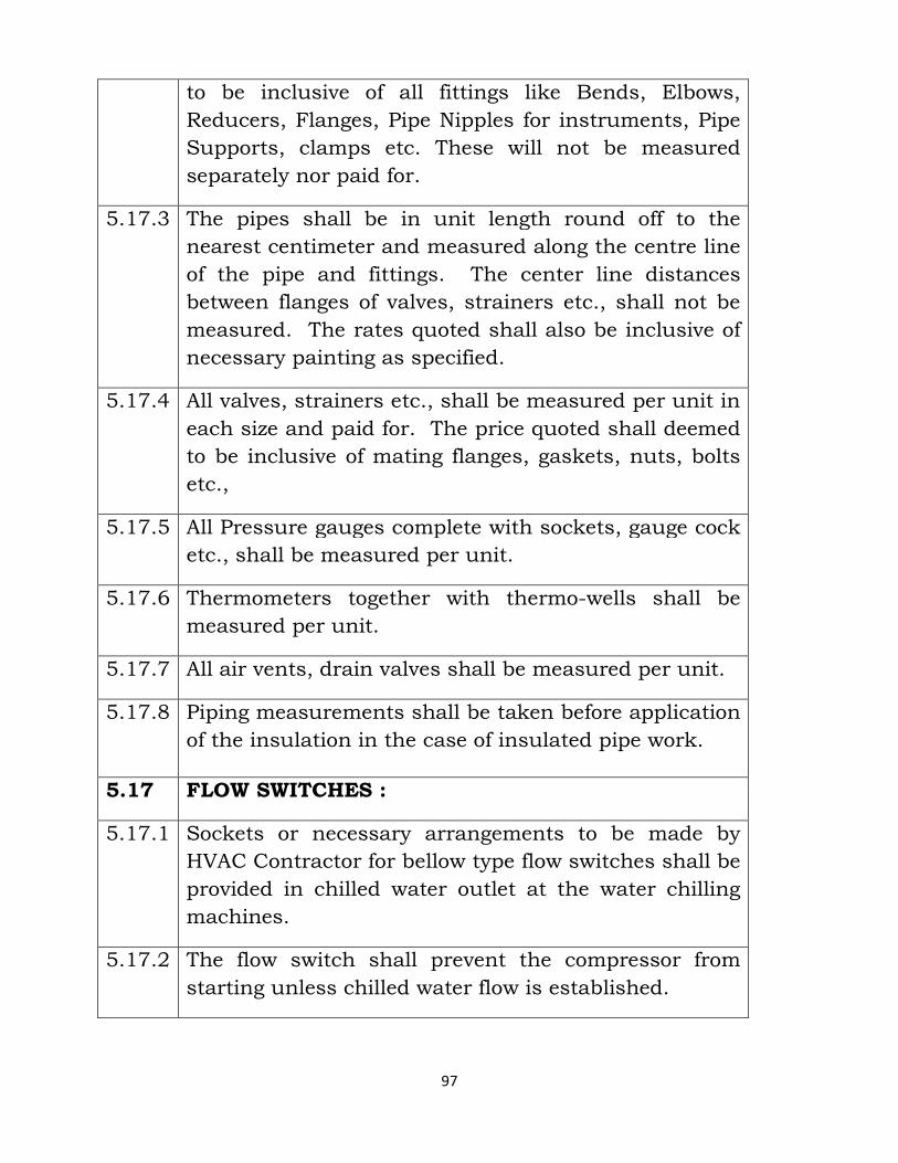
97
to be inclusive of all fittings like Bends, Elbows,
Reducers, Flanges, Pipe Nipples for instruments, Pipe
Supports, clamps etc. These will not be measured
separately nor paid for.
5.17.3 The pipes shall be in unit length round off to the
nearest centimeter and measured along the centre line
of the pipe and fittings. The center line distances
between flanges of valves, strainers etc., shall not be
measured. The rates quoted shall also be inclusive of
necessary painting as specified.
5.17.4 All valves, strainers etc., shall be measured per unit in
each size and paid for. The price quoted shall deemed
to be inclusive of mating flanges, gaskets, nuts, bolts
etc.,
5.17.5 All Pressure gauges complete with sockets, gauge cock
etc., shall be measured per unit.
5.17.6 Thermometers together with thermo-wells shall be
measured per unit.
5.17.7 All air vents, drain valves shall be measured per unit.
5.17.8 Piping measurements shall be taken before application
of the insulation in the case of insulated pipe work.
5.17 FLOW SWITCHES :
5.17.1 Sockets or necessary arrangements to be made by
HVAC Contractor for bellow type flow switches shall be
provided in chilled water outlet at the water chilling
machines.
5.17.2 The flow switch shall prevent the compressor from
starting unless chilled water flow is established.
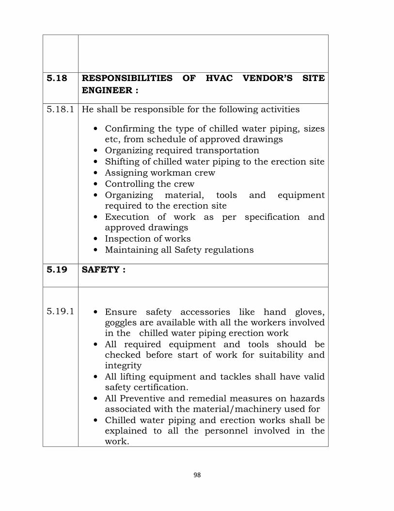
98
5.18 RESPONSIBILITIES OF HVAC VENDOR’S SITE
ENGINEER :
5.18.1 He shall be responsible for the following activities
• Confirming the type of chilled water piping, sizes etc, from schedule of approved drawings
• Organizing required transportation • Shifting of chilled water piping to the erection site • Assigning workman crew • Controlling the crew • Organizing material, tools and equipment required to the erection site
• Execution of work as per specification and approved drawings
• Inspection of works • Maintaining all Safety regulations
5.19 SAFETY :
5.19.1
• Ensure safety accessories like hand gloves, goggles are available with all the workers involved in the chilled water piping erection work
• All required equipment and tools should be checked before start of work for suitability and integrity
• All lifting equipment and tackles shall have valid safety certification.
• All Preventive and remedial measures on hazards associated with the material/machinery used for
• Chilled water piping and erection works shall be explained to all the personnel involved in the work.
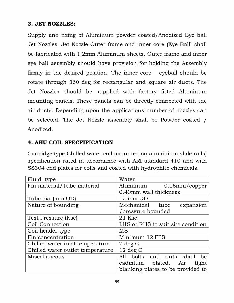
99
3. JET NOZZLES:
Supply and fixing of Aluminum powder coated/Anodized Eye ball
Jet Nozzles. Jet Nozzle Outer frame and inner core (Eye Ball) shall
be fabricated with 1.2mm Aluminum sheets. Outer frame and inner
eye ball assembly should have provision for holding the Assembly
firmly in the desired position. The inner core – eyeball should be
rotate through 360 deg for rectangular and square air ducts. The
Jet Nozzles should be supplied with factory fitted Aluminum
mounting panels. These panels can be directly connected with the
air ducts. Depending upon the applications number of nozzles can
be selected. The Jet Nozzle assembly shall be Powder coated /
Anodized.
4. AHU COIL SPECFIFICATION
Cartridge type Chilled water coil (mounted on aluminium slide rails)
specification rated in accordance with ARI standard 410 and with
SS304 end plates for coils and coated with hydrophite chemicals.
Fluid type Water
Fin material/Tube material Aluminum 0.15mm/copper 0.40mm wall thickness
Tube dia-(mm OD) 12 mm OD
Nature of bounding Mechanical tube expansion /pressure bounded
Test Pressure (Ksc) 21 Ksc
Coil Connection LHS or RHS to suit site condition
Coil header type MS
Fin concentration Minimum 12 FPS
Chilled water inlet temperature 7 deg C
Chilled water outlet temperature 12 deg C
Miscellaneous All bolts and nuts shall be cadmium plated. Air tight blanking plates to be provided to
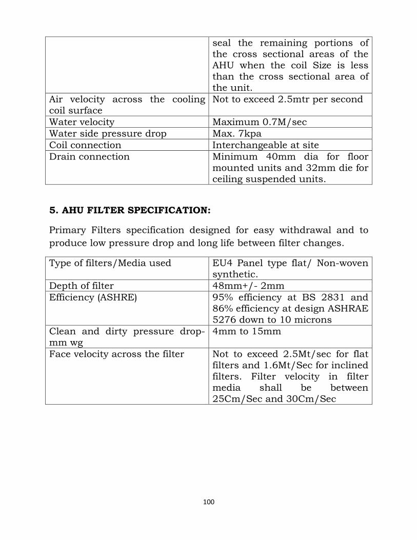
100
seal the remaining portions of the cross sectional areas of the AHU when the coil Size is less than the cross sectional area of the unit.
Air velocity across the cooling coil surface
Not to exceed 2.5mtr per second
Water velocity Maximum 0.7M/sec
Water side pressure drop Max. 7kpa
Coil connection Interchangeable at site
Drain connection Minimum 40mm dia for floor mounted units and 32mm die for ceiling suspended units.
5. AHU FILTER SPECIFICATION:
Primary Filters specification designed for easy withdrawal and to
produce low pressure drop and long life between filter changes.
Type of filters/Media used EU4 Panel type flat/ Non-woven synthetic.
Depth of filter 48mm+/- 2mm
Efficiency (ASHRE) 95% efficiency at BS 2831 and 86% efficiency at design ASHRAE 5276 down to 10 microns
Clean and dirty pressure drop-mm wg
4mm to 15mm
Face velocity across the filter Not to exceed 2.5Mt/sec for flat filters and 1.6Mt/Sec for inclined filters. Filter velocity in filter media shall be between 25Cm/Sec and 30Cm/Sec
101
6. ELECTRICAL:
ELECTRICAL INSTALLATION
10.0 Scope
Scope of this section comprises the supply and installation of
all electrical equipment such as motors, motor control centers,
starters, cables, interlocks, etc.
10.1.1 Codes, Standards and Statutory Regulations
10.1.2 Codes, Standards and statutory regulations to be used
for design and constructions are given below. In general
all equipment, material as well as design and
constructions shall be in accordance with the latest
issues of Indian and relevant standards currently in
force. The installation shall be carried out in accordance
with the Indian Electricity Act and Rules.
10.2 Electric Supply System/Rated Voltage
10.2.1 415 Volts, 3phase, 4wire, 50 Hz with solidly grounded
neutral.
Variation in electric supply under which motor shall be
operated continuously without any adverse effect will be as
follows:
a) Voltage : +/- 5%
b) Frequency : +/- 5% variation
102
c) Any combination of voltage and frequency
10.3 Equipment and Materials
10.3.1 All equipment shall be as per specifications, and/or
drawings supplied along with the tender documents.
Equipment/materials shall be suitable for local climatic
conditions as specified in the tender.
10.3.2 All equipment shall be of robust construction. Enclosure
of equipment shall be dust, damp and vermin proof.
Equipment for outdoor installation shall have weather proof
enclosures requiring no further protection by the purchaser.
10.3.3 Approval
The contractor shall be responsible for obtaining approval of
drawings from statutory/local authority as required.
10.4 Motor Control Centre
10.4.1 Motor Control Centre shall consist of incoming switch
fuse units isolator and a starter mounted inside the wall or
floor mounting type cubicle made out 2 mm thick MS sheet.
Anti corrosion and phosphatising treatment shall be given to
the sheets by a standard 5 tank/7 tank process.
10.4.2 All feeders shall be provided with two position (on-off)
isolators, load break and quick make and break type. All
isolators shall be suitable for front of board operation.
103
Isolators for motor feeders shall preferably be of the ‘motor
duty’ type i.e capable of interrupting the locked rotor current
of induction motors, which will be 6/8 times the full load
current.
10.4.3 Isolators shall be interlocked with door to prevent
opening or closing of the door in the closed (‘ON’) position of
the isolator, in case of compartmental type of feeders. All live
terminals on the isolators shall be adequately shrouded to
prevent accidental contact and danger to the personnel.
a) Caution name plate “CAUTION LIVE TERMINALS” shall be
provided at all points where the terminals are likely to
remain live and isolation if possible only at remote by
broken filaments. Lamp covers shall be provided with
interchangeable colored lenses of per spex or equivalent
unbreakable materials. Lenses should not get discolored in
course of time, due to the heat generated by the lamps.
Name plates showing the condition indicated by the lamp
shall be affixed near to the lamps.
b) Rating of terminal blocks for power and control circuits
shall be at least 30 Amps and 15 Amps respectively.
Terminals in control circuits shall be suitable for receiving
one conductor per terminals of specified sizes. Terminals
for power circuits shall be designed for receiving aluminium
conductors and shall be suitable for receiving copper
conductors. Star/lock/Shake proof or Spring Washers
shall provide to prevent sparking due to vibrations. Special
terminals with copper strips mounted on insulating
104
supports may be provided for large cables. Where
terminals, suitable extension bars with off-set may be
provided.
c) Location of controls for motor starters or other feeders shall
be specified. Normally one ‘stop’ push button with stay-put
feature (lockable) and one reset push one button for hand
resetting of BNMR shall be provided on the door of the
compartment. Coolers used for push buttons shall be as
follows:
Stop push button - Red
Start push button - Green
Reset push button - Black
(Note: In case ‘Stop’, and ‘Reset’ are combined, only red colors
will be used.) Name plates indicating the function of the push
button shall be affixed near to the push buttons.
10.4.3.1 Wiring
a) Internal wiring of MCCs for power and control shall be
carried out with copper conductor PVC insulated cables of
PVC covered copper/aluminum tapes.
b) Wiring of components mounted on doors shall be carried
out with single stand 2.5 sq.mm copper conductor flexible
cables. Wires and cables shall be neatly arranged and
bunched together with suitable clamps made of insulating
material. Wire harnesses shall be adequately supported
along the MCC metal work.
105
c) Identification ferrules or tags shall be attached to each wire
at each point connection.
d) Sizes of conductors for power wiring shall be determined by
the manufacturers on the basis of full load current under
specified conditions, protective fuse rating and appropriate
rating factors as applicable. Minimum sixe of conductor
shall be 2.5 sq. mm. Minimum size of conductor for control
wiring shall be 1.5 sq. mm.
e) The following color code shall be used for determining the
colors of wires used for internal wiring. Manufacturer shall
obtain specific approval of the purchases, if this colour
coding cannot be observed for any reason whatsoever:
Earth - Green
Neutral - Black
230 V, A.V. phase - Red/yellow/Blue,
to neutral Black
f) All wiring shall be carried out in accordance with approval
and certified panel wiring diagrams. Vendor shall check all
wiring from point to point for correctness. All wires shall be
numbered and the numbers shall be indicated on the
relevant drawings.
10.4.3.2 Ear thing
All metal work of the MCC and non-current carrying metallic
parts of the equipment in the MCC shall be securely bonded
together by adequate means e./g. use of earthing washer for
106
bolted connections or tapped holes for mechanical
connections,. One copper earth bus running through the
entire length of the MCC shall be provided preferably along
with the terminal chambers. Size of the earth bus shall be
such as to withstand phase to earth or 2 phases to earth short
circuit for one second. The minimum size of the bus bar shall
be 25 x 3 mm. All the terminals complete with hardware and
cable sockets shall be provided on the earth bus for
connection to external system.
10.4.3.3 Name Plates and Labels
a) One name plate giving designation of the MCC shall be
affixed prominently on to the MCC (Details of designation
will be given). Each feeder shall also be labeled giving
following details:
i) Feeder No.
ii) Feeder Designation (Eqpt. Ref No. etc)
iii) Description
iv) Rating (HP/KW/Amps)
b) All components whether mounted inside the MCC or on the
door shall be permanently and clearly labeled with their
reference number and /or letter or their function (rating of
fuse shall form part of the fuse designation).
107
c) Labels for feeder designation shall be of laminated plastic or
rear engraved per spex with white letters on black
background.
d) Labels for feeder designation shall be fixed on the doors on
respective feeders with chrome-plated self tapping screws.
Designation labels shall be identical in size to permit
interchanging if required later.
10.4.3.4 Miscellaneous
a) All hardware used shall be plated or passivated to resist
corrosion. Type of plating or passivation shall be subject
to the approval of the Consultant. All fixing screws shall
preferably be raised head type.
10.5 Drawings
a) Contractor shall furnish the following to the Consultant for
his approval before commencement of fabrication.
i) General Arrangement Drawing showing overall
dimensions, arrangement of feeders, foundation plan,
positions, of cables entries, weight of MCC and sections in
which MCC will be despatched.
ii) Single Line Diagram for the MCC showing rating of
various components used for all feeders complete with
feeder numbers, designations, descriptions, ratings etc.
iii) Schematic and panel wiring diagrams for all feeders.
iv)Terminal plan for MCC, showing feeder numbers,
terminal numbers and terminal markings.
108
b) After the final approval, six prints and one clear film
reproducible of each of the above drawings shall be
furnished.
c) The contractor shall note that he shall bear full
responsibility for any error, discrepancies, omissions, etc.
in the drawings irrespective of whether such drawings have
been approved or no. Approval of drawings shall not relieve
the Contractor of his liability to complete the work in
accordance with the specifications and other conditions of
contract not shall it exonerate the vendor from any of his
guarantees.
10.6 Testing and Inspection
a) The following tests shall be carried out on the Motor Control
Centers after completion of all work :
(i) All power and control circuits for MCCs shall be tested for
insulation resistance switch a 500 volt megger, before and
after the high voltage test.
(ii) High voltage test shall be carried out on all power control
circuits at 2000 volts A.C. voltage applied for one minute.
(iii) Low voltages continuity test on all power circuits shall be
carried out from bus bars to the outgoing terminals of each
feeder with switches and contractors in closed position.
(iv) All control circuits and operations of equipment for all feeders
shall be checked with only control supply made available to
ensure satisfactory operation of all equipment such as push
buttons, BMR reset, indicating lamps, timing relays etc. All
109
contractor coils shall be checked for presence of humming or
chattering. Special requirements for various feeders indicated
in the purchase data sheets shall also be checked.
(v) Earth continuity test shall be carried out with a low voltage
supply of not more than 6 volts, between various non-current
carrying metallic parts of equipment, steel work etc. and the
earth bus provided in the MCC.
(vi) Operation of all instruments and meters provided on the MCC
shall be checked.
b) All the tests listed above shall be carried out in the present
of Owner’s representative, during final inspection.
Contractor shall provide all facilities such as power supply,
testing instruments and apparatus required for carrying out
the tests.
c) Contractor shall give a notice of not less than two weeks for
inspection and testing by the owner’s representative.
10.7 Electric Motors
10.7.1 Rating & Duty
a) Rating of the motors shall be as indicated in the Schedule of
Equipment. Where the equipment supplied needs a higher
rated motor, the Contractor shall clearly point out and
motors shall be offered accordingly.
b) All motors shall be rated for continuous duty at maximum
output.
c) Rated voltage for three phase motors shall be 415 volts.
110
10.7.2 Design Features
a) Motor body shall be of close grained cast iron construction
and shall be provided with lifting hooks or eye bolts. The
motor along with the fan and half coupling shall be
dynamically balanced
b) Fan provided for fan cooled motor shall be non-directional
type.
10.7.3 Enclosure / Protections
a. Enclosure for motors shall be totally enclosed fan cooled (TEFC)
unless other specified – SPDP motors shall be used only where
the desired out is not obtainable in a TEFC frame.
b. All outdoor motors shall be TEFC weather proof type.
c. Degree of protection for all motors shall be (IP 44 as per IS 491).
d. Two earthing terminals comprising terminals studs, plain
washers, one spring washer and not shall be provided on
opposite sides of the frame. Studs shall be suitable to receive
appropriate size of earth conductor.
10.7.4 Terminals Box
a. Terminal box shall be ample size, suitable for termination of
aluminum conductor cables (with cable sockets) which may be
substantially de rated for conditions of installation.
b. Motor terminals shall be stud type, substantially designed and
well insulated from the frame. Each terminal shall be complete
with two flat washer’s one lock nut.
c. Number of terminals shall be as given below:
Squirrel cage motors up to 3.7 Kw - 2 Nos.
111
Squirrel cage motors up to 3.7 Kw (with tinned copper links for
delta connection) - 3 Nos.
Slip Ring Motors - 3 Nos.
d. Terminal boxes of all motors shall be rotatable in steps of 90
degrees, without distributing the motor winding connections to
the terminal block. Separate terminal box shall be provided for
connections to anti condensation heaters in case of motors about
50 HP. If heater terminals are provided in the main terminal box,
then insulating barrier shall be provided between them with
caution name plate affixed on the terminal box. “CAUTION – LIVE
HEATER TERMINALS”.
e. Separate terminal boxes for starter and motor leads to be
provided for slip ring motors. Where it is not feasible, an
approved type of insulating barrier to the provided.
10.7.5 Temperature Rise
The temperature rise of motors when tested in accordance
with IS 325 shall not exceed the limits specified therein.
10.7.6 Starting of Motors
a) All squirrel cage motors shall be suitable for full voltage starting.
Motors of 10 HP and above will generally be started with
star/delta or auto transformer starters which, in addition to
protective devices, shall be provided with single phasing
preventer.
b) Starting current at full voltage of slip ring motors shall be limited
by the rotor resistance starter. Motor manufacturer shall furnish
appropriate value of external resistance required to limit the
112
starting current as well as to obtain the required torque.
However starting current with slip rings shorted shall not exceed
600% of full load current. starting current of squirrel cage
motors with full voltage starting shall not exceed 600% of the full
load current with tolerance specified in IS 325
c) Starting torque of squirrel cage motor started on full voltage shall
not be less than 200% of the full load torque. Pull out torque of
motors shall not be less than 200% of the full load torque.
10.7.7 Insulation
a) All motors shall have Class ‘D/F’ insulation unless the
ambient temperature or other conditions necessitate
another class of insulation.
b) All materials used in the construction of motors shall be
non-hygroscopic.
10.7.8 Painting
All motors shall be painted in an approved manner using two
priming coats and two finish coats. The final colour shall be
to the Owner’s requirements.
10.7.9 Performance Particulars
Following performance particulars for all motors to be
furnished well in advance before finalising orders for motors:
a) Make
b) Type
c) Enclosure
d) Class of Insulation
e) Temperature Rise above 40 Deg.C ambient
113
f) Rated Output
g) Speed
h) No load current
i) Full load current
j) Locked rotor current
k) Starting torque (DOL)
l) Efficiency at full load, ¾ load, ½ load
m) Power factor at full load, ¾ load, ½ load
n) Details of rating for space heater
o) Max. Size of alminium conductor cable which could be
connected to motor
p) Rotor current at rated output
q) Value of rotor resistance for different torque values.
10.8 MV Distribution Boards
10.8.1 Construction
The salient features of constructions panels shall be as
follows:
a) Sheet Steel – 2 mm thick for frames, cable gland plates and
equipment mounting plates and 1.6 mm thick for front and
rear doors and covers.
b) Welded construction with shipping section bolted together.
All such joints to be provided with gasket. Lifting lugs to be
provided.
c) The cubicles shall be totally dust and vermin proof
conforming to IP 54 of IS 2147.
114
d) All doors to be hinged type except bus bar chamber covers
which shall be bolted type. The panel shall be of flush front
design, suitable for access from front and rear.
e) The construction shall be such as to facilitate easy
extension at both ends.
f) The design shall be such as to have individual feeders in
separate compartments, with proper barriers between
adjacent feeders, bus bar chamber and cable box chambers.
10.8.2 Painting
All sheet steel work shall be properly cleaned and decreased.
Rust and scale shall be removed by picking and phosphating.
After phosphatising, two costs of primer shall be applied
followed by two coats of finishing synthetic enamel paint of
approved shade as per IS-5. The painting shall be stove
enamel.
10.8.3 Air Circuit Breakers
a) The circuit breaker shall be air-break, horizontal draw out
feature shall show 3 positions viz SERVICE, TEST and
ISOLATED. These positions along with ‘OPEN’ and ‘CLOSE’
positions shall be visibly marked.
b) All positions shall have provisions for locking. The ACB
shall have shutter assembly and arc-chutes and mechanical
trip features.
c) The ACB shall have 6 NO + 6 NC auxiliary contacts rated at
10A 240 V Ac
115
d) ‘RED and ‘GREEN’ indicating lamps shall be provided on
the cubicle.
e) The ACB door shall not have any lamps or instruments. All
such accessories shall be mounted on a separate
compartment.
f) The ACB shall have proper interlocks such that ir cannot be
‘plugged in or our ‘SERVICE’ position, if the breaker is in
‘ON’ condition. It shall not be possible to operate as circuit
breaker unless it is properly engaged in any of the three
positions.
g) The ACB shall have series C1 operated over current and
short circuit releases with facilities to mount the under
voltage and shunt-trip releases.
h) The operating mechanism shall be independent, manual
spring charged stored energy type. The mechanism shall
ensure quick-break, quick make action and the ACB shall
be trip free in operation.
10.8.4 Air Break Switches
a) The air break switches shall be of AC23 (heavy) duty, quick
make-quick break, fault-make type as per IS 4047. The
contacts shall be silver plated.
b) The switches shall be capable of withstanding the
mechanical and thermal stresses produced by overloads
and short circuits.
116
c) All switches of all ratings shall have inter-locks with the
compartment doors. Switches of 250A and above shall be
possible to intention- ally defeat the interlocks if required.
d) ‘RED’ indicating lamp shall be provided ‘ON’ indication.
10.8.5 Fuses
All fuses shall be of HRC cartridge fuse-link type having a
certified rupturing capacity of not less than 46 KA at 415 volts
Ac. The HRC fuses shall conform to IS 92214 1979. All fuses
shall have visible indication to indicate ‘Blown’ condition.
10.8.6 HRC Fuse Carriers
a) The HRC fuse carriers/bases shall be of high grade phenolic
mouldings. The contacts shall be silver plated and the
contact blocks shall be suitable to receive the rated
conductors of aluminium.
b) The fuse carriers shall have an aperture to view the
conditions of HRC fuse mounted inside.
10.8.7 Contractors
a) The motor starter contractors shall be of the electro-
magnetic, double- break, non-gravity type rated for un
interrupted duty suitable for operation under AC 3
utilisation category as per Is 2959. The contacts shall be
silver plated.
b) 2 No and 2 NC auxiliary contacts shall be included.
c) The operating coil have Class ‘E’ insulation of wire and
shall be suitable for operation of any specified control
supply system.
117
10.8.8 Thermal Overload Relays
a) The thermal overload relays shall be 3 element, positive
action, ambient temperature, compensated with a time log
and adjustable settings. The setting range shall be selected
in accordance with the ratings of the motor.
b) The relay shall be self-reset/hand reset as called for in the
case of hand-reset the reset button shall be fixed on the
compartment door.
c) The relay shall have at least one ‘NC’ on ‘No’ or one change-
over contact.
10.8.9 Moulded case circuit breakers
a) The moulded case circuit breakers, MCCBs shall be provided
where certified. The MCCBs shall conform to the latest
applicable IS 2516-1977.
b) For AC circuits the MCCBs shall be triple pole construction and
shall have independent manual opening and closing mechanism.
The mechanism shall be quick make and quick break type and
the breakers shall be trip-free in operation. The ‘ON’, ‘OFF’ and
‘TRIP’ mechanism shall be clearly indicated.
c) Bolted type neutral link to be provided with TP MCCB.
d) It shall be possible to mount accessories on the MCCBs li9ke
shunt – trip and under voltage release, alarm contacts etc.
e) The MCCBs shall have thermal/static trip devices
f) The MCCBs shall have reputed capacities as specified in BOQ /
Single Line Diagram.
118
10.8.10 Miniature Circuit Breakers
The MCBs shall be of single p[ole, double pole, triple pole, or
four pole as required. The MCBs shall be of magnetic type
with a maximum rupturing capacity of 9 KA at 415 V
10.8.11 Current Transformers
a) The CTs shall be of dry type and shall have short-time
withstand rating equal to the short-time withstand rating of
the associated switchgear for 1 second
b) The measuring instrument CTs shall be of 15 VA, minimum
accuracy class 1.0 and an instrument safety factor of 5 .
10.8.12 Indicating Instruments and Meters
a) Electrical indicating instruments shall be 72 mm/
96,,/144mm square size. Suitable for flush mounting.
b) The zero adjustment shall be done from outside the cover.
c) The dials to be parallax free with black numerals on a white
dial.
10.8.13 Indicating Lamps
a) Indicating lamps shall be of the filament type of low watt
consumption, provided with series resistors and HRC fuse
link for promotion.
b) The lens shall be easily replaceable from the front.
10.8.14 Control and Selector Switches
a) The control and selector switches shall be of rotary type,
adequately rated for the application but with a minimum
rating of 10 Amps at 240 V AC and 1 Amp at 220 at V DC.
The plates shall have clear position markings.
119
b) The control switches shall have pistol grip handles spring
return to normal. The selector switches shall have oval
knobs have shall be contact stay-pur type.
10.8.15 Push Buttons
a) The push buttons shall be of the momentary contact, push
to actuate rated for 10 A at 240 V AC and 1 A 220 VDC.
The ‘START’ push buttons shall be green and shrouded.
The ‘STOP’ push button shall be red and un shrouded. All
other push buttons shall be black.
10.8.16 Main and Auxiliary Buses
a) The bus bars shall be of high conductivity aluminium alloy
of E91E b grade. The bus bar shall be of uniform cross-
section throughout the length of the panels.
b) All main and auxiliary bus bars shall be insulated with
sleeves. The sleeves shall be of high dielectric strength,
non-corrosive and of phase and neutral colours.
c) The bus bars shall be supported on cast epoxy / DMC/
fibre glass insulators and he spacing of the supports shall
be such as to withstand the stresses of the short circuit
currents the bus bar spacing shall be adequate for 3 phase
voltage up to
600 V.
d) The bus bar shall be a chosen for specific current ratings
with a minimum density of 1 amp for sq. mm area.
120
10.8.17 Internal Wiring
a) All internal wiring shall be carried out with 110 V/650 V
grades PVC insulated stranded conductor copper wires. The
minimum size of wires shall be 2.5 sq. mm copper and for
CTs also 2.5 sq. mm copper
b) All individual control and CTs wiring shall be labeled with
engraved identifications ferrules, yellow in color with black
letters.
c) All spare auxiliary contacts of contactors and relays shall be
wired to control terminal blocks.
10.8.18 Terminal Blocks
a) Terminal blocks for power and control shall be of reputed
make stud types, with washers, nuts and lock-nuts. All
adjacent terminals shall have insulating barriers.
b) All power terminal blocks shall be appropriately rated for
current with a minimum of 30 Amps. The control terminal
blocks shall be rated for a minimum of 10 A and suitable for
at least 2 conductors each of 2.5 sq.mm
c) All sets of power and control power terminal blocks shall be
identified with engraved plastic labels, black background
and white letters
10.8.19 Identification Labels
All labels shall be back plastic with white engravings of letters
of minimum 6 mm sizes
121
10.8.20 Earthing
All switchgears shall have continuous run of earth bus bar.
The size and materials of the earth bus-bar shall be specified.
10.8.21 Tariff Advisory Committee and CPRI Tested
10.8.22 Tests
A) High voltage test at 2.5 KV
B) Power and control circuits continuity Tests
C) Insulation Resistance Test with 1000 V megger
D) Operational Test
E) Three sets of Test Certificates to be submitted
10.8.23 Drawings
Three sets of general arrangement drawings and wiring
diagrams of all types of feeders shall be submitted.
10.9 Control Stations
10.9.1 Control station shall be of cast iron or cast aluminium
enclosures, consisting of ‘START’ and ‘STOP’ push buttons and
shall have stay put feature of twist unlock type.
10.10 Cables and Accessories
10.10.1 All cables shall be heavy duty PVC insulated armoured
and PVC sheathed of 1.1 KV grade. Aluminum conductor
cables shall be used for power and copper conductor cables
shall be used for control wiring.
10.11 Glands
10.11.1 Glands used for termination shall be compression type.
Cable glands shall be with single/double seal and cone and
clamp for armoured clamping
122
For safe and indoor areas, glands with single seal and for
outdoor installation and hazardous areas, gland with double
seals will be used. For use ion corrosive areas, glands shall be
coated with rust proofing lacquer after installation provided
with PVC hoods.
10.11.2 Cable lugs shall be dowell or equivalent approved make,
suitable for connection of aluminium conductor cables. The
cable lugs shall be of tinned copper and of soldering type for
solid conductor cables. For stranded conductor cables,
crimping type, tinned copper cable lugs shall be used.
10.12 Conduits and Accessories
Conduits wherever used with prior approval of the Contractor
shall be of GI heavy gauge.
10.13 Saddles
10.13.1 Saddles to be used for cleating the cables or conduits
shall be fabricated from MS or aluminum strips or any other
approved material and shall be painted and dried before
installation with chemical works type paint.
10.14 Cable Tags and identification Ferrules
10.14.1 Cable tags and identification ferrules provided on cable
cores/ wires shall be of PVC/plastic. Cable tags shall be
provided at every 15 meters and at all bends or change in
routes.
10.15 Structural Steel
10.15.1 This shall include MS angles, channels, flats etc required
for fabrication of cable trays, local supports for cables, control
123
stations, etc. All steel sections shall be new and conform to IS
226.
10.16 Miscellaneous Materials
10.16.1 These shall include solders, fluxes, adhesive, insulating
tapes, PV sleeves, petroleum conducting jelly etc.
10.17 Earthing Material
10.17.1 Copper strips or wires of suitable sections shall be used
for earthling in accordance with IS 3403.
10.17.2 All 3 phase 415 Volts equipment shall be earthed at two
points and all single phase equipment at one point.
10.18 Painting
10.18.1 All metal work and metal parts of the MCC shall be
thoroughly cleaned to remove ruse, scale grease or any other
matter suitable anti-corrosion treatment such as
phosphatising shall be given to the metal work. All exposed
surfaces of the metal work shall then be a priming coat of zinc
chromate or equivalent and finished with two coats of paint of
specified shade.
10.19 Drawing
10.19.1 contractor shall submit 3 copies of control of schematic
wiring diagram for refrigeration unit showing all protections
and interlocks for Consultant’s review and approval
10.20 Installation
124
10.20.1 Motor Control centers
Motor Control Centers shall be installed on welded
construction channel framework. Framework shall be
properly grouted by means of foundation bolts or anchor
fasteners.
10.20.2 Cable Termination
10.20.3 PVC cables shall be terminated with compression type
glands. For outdoor installation double seal compression
glands shall be used. All cables shall be connected by means
of suitable crimping type cable lugs. All connections shall be
secure and vibration proof. All contact surface shall be coated
with petroleum conducing jelly before connections are made.
10.20.4 Earthing
All metallic frame work and non-current carrying metallic
parts and enclosures of electrical equipment such as MCCB,
motors, control station etc. shall be bonded to one another and
earthed by means of two separate earth conductors and
connected to the plant earthing system.
10.20.5 Motors
All motors shall be installed on a common foundation with the
driver equipment coupled through flexible couplings or belt
drive.
Leveling and alignment of motor and driven equipment to be
carried out as per IS per 900 to avoid undue strain on motors.
125
Insulation resistance of motor shall be measured before
commissioning. In no case insulation resistance should be
dried out as per procedure laid on IS 900. Pre-commissioning
mechanical checks shall be carried out as per IS 900
Cable termination and earthing of motors shall be carried out
by Electrical Contractor
On commissioning of motor, any defects like access current,
bearings getting hot, under vibration or noise etc are observed,
it will have to be made good by the contractor without any
extra cost.
10.21 Testing and Commissioning
10.21.1 Operation Test
a) Energize only control circuits and carry out closing and
tripping operation. Check tripping of circuit breakers by
manual operation of protective relay contacts. Check
lockout conditions for closing of circuit breakers by
simulating the required conditions. Check control,
indications, sequence interlocks and alarms.
b) Polarity and connections of instrument transformers check
for correctness of CT and PT connections provided with
transformer. Check electrical continuity of secondary
circuits with ELV tester. Adjust spacing of arcing horns/
rod gaps.
c) Check operation of instruments, meters, relays and
tripping of circuit breakers by primary/Secondary injection
126
as specified. This test will be carried out only if specifically
called for by Contract Documents.
d) Check continuity of power circuits and each continuity of all
n on-current carrying metallic parts with a low voltage (6V
or less) continuity tester.
e) Carry out IIV test on power and control circuits if
specifically called for in contract documents
10.21.2 Motors
Check equipment for free movement of rotor and play,
lubrication and for any other mechanical defects and direction
of rotation.
Check slip rings, brushes, brush holders etc for satisfactory
conditions. Insulation test of motors between winding and
ground shall be measured. Use 500 V megger for MV motors
and 1000 V megger for HV motors. Check electrical continuity
with ELV tester.
10.21.3 Control Cables
Carrying out insulation test on all power and control circuits
to be done. Check all equipment for satisfactory operation and
correct wiring.
10.21.4 Wiring
Insulation test between each phase and neutral and between
each phase/ neutral and ground.
In case of lightening wiring, insulation test shall be carried out
on lighting feeders with branch circuits open. Branch circuits
127
shall be tested separately with lamp holders, plug receptables
and lighting fittings in position but without lamps. In Case of
directly buried cables, insulation resistance of cables shall be
sequence.
10.21.5 Earthing System
Continuity test for earth continuity conductors with ELV
tester.
10.21.6 Operation test
After successful completion of the above tests, operational
tests shall be carried out by the contactor for checking the
connections done by him and satisfactory operation of all the
equipment supplied by him. This test shall be carried out
initially without energizing power circuits. Various control
conditions shall be simulated for the purpose of this test. The
Contractors, free of cost, shall rectify any defects during the
tests such as blown fuses, damage to devices. e.g. Incoming
Terminals of Incomer.
10.21.7 Fuses & Fuse Fittings
a) All fuses shall be of the non-deteriorating, high rupturing
capacity, link, mounted in suitable fuse carriers or fuse
bases.
10.21.8 Contactor
a) Contactors shall be magnetic, air break type, generally in
accordance with BS 775/IS 2959.
128
b) All contactor in power circuits of motor starters or other
feeders shall be adequately rated for the duty required and
operating conditions. Minimum rating shall, however, not
be less than 16 amps.
c) Contactor coils shall preferably be of draw out type for easy
replacement. Coil voltage shall be 220 V AC. Contractor
coils shall operate satisfactorily between 110% and 85% of
the nominal coil voltage. Drop off voltage for AC coils shall
be between 80% and 45% of the nominal voltage.
d) Making and breaking capacities of the Contactor shall be
suitable for AC2 and AC3 categories of duty as per IS 2959
unless the Contactor are required for special duty such as
inching or plugging duty or capacitor duty, in which case,
they will be suitably de rated.
e) Each Contactor shall be provided with 4 normally open and
4 normally closed auxiliary contacts or as required by the
control scheme. If necessary, auxiliary relays or contractors
may be provided to obtain necessary number of auxiliary
contacts. Auxiliary contacts shall preferably be convertible
from NO to NC and vice versa.
10.21.9 Protective Devices
d) All feeders shall be protected by appropriate protective
devices such as fused, combined bimetallic thermal
overload and single phasing preventer relays.
e) Single phasing preventer relays (SPPRS) shall operate on
the principle of unbalanced currents due to single phasing.
BMR’s and SPPRs shall preferably have a change over
129
contact which can be converted from hand reset to self reset
and vice versa and used for contractor control as well as
alarm/indication.
f) Current transformer, when specified, shall be of bar
primary, ring type or wound type, and in accordance with IS
2705 or BS 2046 or 81. Class and ratio of CTs shall be
specified. VA burden of CTs shall be suitable for the load
burden.
g) Ammeters (144 square) voltmeters, PF meters, Run Hour
meters and Kilowatt Hour meters shall be provided and
shall be of industrial grade accuracy, suitable for flush
mounting and in accordance with IS 1248. Suitable
selector switches shall be provided in conjunction with
ammeters and voltmeters.
Indicating Neon lamps used shall be of low voltage, low
burden type with series resistor to increase lamp life and to
protect equipment from short circuits caused.
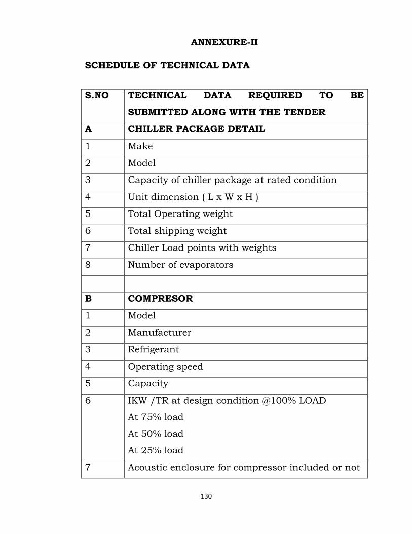
130
ANNEXURE-II
SCHEDULE OF TECHNICAL DATA
S.NO TECHNICAL DATA REQUIRED TO BE
SUBMITTED ALONG WITH THE TENDER
A CHILLER PACKAGE DETAIL
1 Make
2 Model
3 Capacity of chiller package at rated condition
4 Unit dimension ( L x W x H )
5 Total Operating weight
6 Total shipping weight
7 Chiller Load points with weights
8 Number of evaporators
B COMPRESOR
1 Model
2 Manufacturer
3 Refrigerant
4 Operating speed
5 Capacity
6 IKW /TR at design condition @100% LOAD
At 75% load
At 50% load
At 25% load
7 Acoustic enclosure for compressor included or not
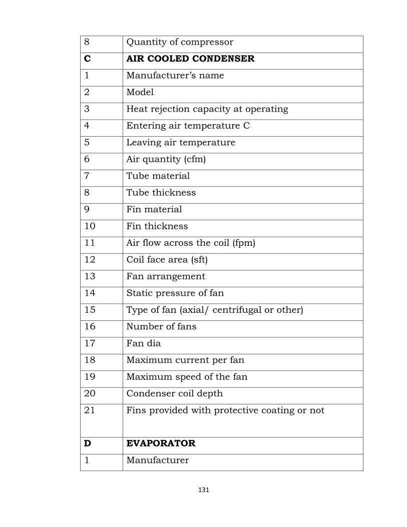
131
8 Quantity of compressor
C AIR COOLED CONDENSER
1 Manufacturer’s name
2 Model
3 Heat rejection capacity at operating
4 Entering air temperature C
5 Leaving air temperature
6 Air quantity (cfm)
7 Tube material
8 Tube thickness
9 Fin material
10 Fin thickness
11 Air flow across the coil (fpm)
12 Coil face area (sft)
13 Fan arrangement
14 Static pressure of fan
15 Type of fan (axial/ centrifugal or other)
16 Number of fans
17 Fan dia
18 Maximum current per fan
19 Maximum speed of the fan
20 Condenser coil depth
21 Fins provided with protective coating or not
D EVAPORATOR
1 Manufacturer
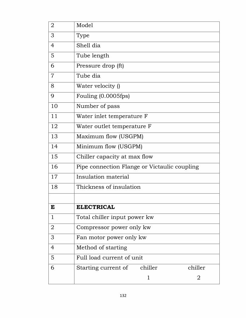
132
2 Model
3 Type
4 Shell dia
5 Tube length
6 Pressure drop (ft)
7 Tube dia
8 Water velocity ()
9 Fouling (0.0005fps)
10 Number of pass
11 Water inlet temperature F
12 Water outlet temperature F
13 Maximum flow (USGPM)
14 Minimum flow (USGPM)
15 Chiller capacity at max flow
16 Pipe connection Flange or Victaulic coupling
17 Insulation material
18 Thickness of insulation
E ELECTRICAL
1 Total chiller input power kw
2 Compressor power only kw
3 Fan motor power only kw
4 Method of starting
5 Full load current of unit
6 Starting current of chiller chiller
1 2
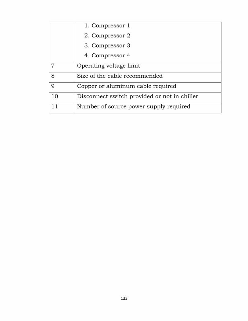
133
1. Compressor 1
2. Compressor 2
3. Compressor 3
4. Compressor 4
7 Operating voltage limit
8 Size of the cable recommended
9 Copper or aluminum cable required
10 Disconnect switch provided or not in chiller
11 Number of source power supply required

134
Note: All tenders received with in complete information or non submission of technical data along with tender will be rejected without any information to tender. ANNEXURE-III
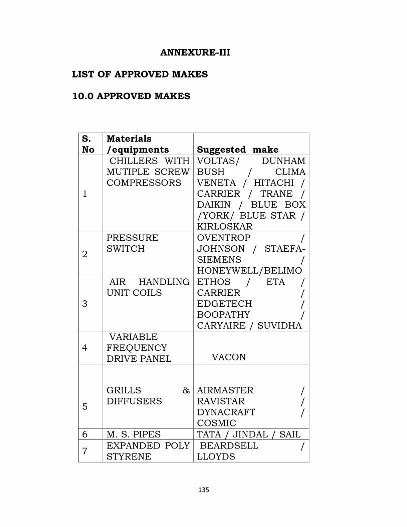
135
LIST OF APPROVED MAKES 10.0 APPROVED MAKES
ANNEXURE-III
S. No
Materials /equipments Suggested make
1
CHILLERS WITH MUTIPLE SCREW COMPRESSORS
VOLTAS/ DUNHAM BUSH / CLIMA VENETA / HITACHI / CARRIER / TRANE / DAIKIN / BLUE BOX /YORK/ BLUE STAR / KIRLOSKAR
2
PRESSURE SWITCH
OVENTROP / JOHNSON / STAEFA-SIEMENS / HONEYWELL/BELIMO
3
AIR HANDLING UNIT COILS
ETHOS / ETA / CARRIER / EDGETECH / BOOPATHY / CARYAIRE / SUVIDHA
4 VARIABLE FREQUENCY DRIVE PANEL
VACON
5
GRILLS & DIFFUSERS
AIRMASTER / RAVISTAR / DYNACRAFT / COSMIC
6 M. S. PIPES TATA / JINDAL / SAIL
7 EXPANDED POLY STYRENE
BEARDSELL / LLOYDS
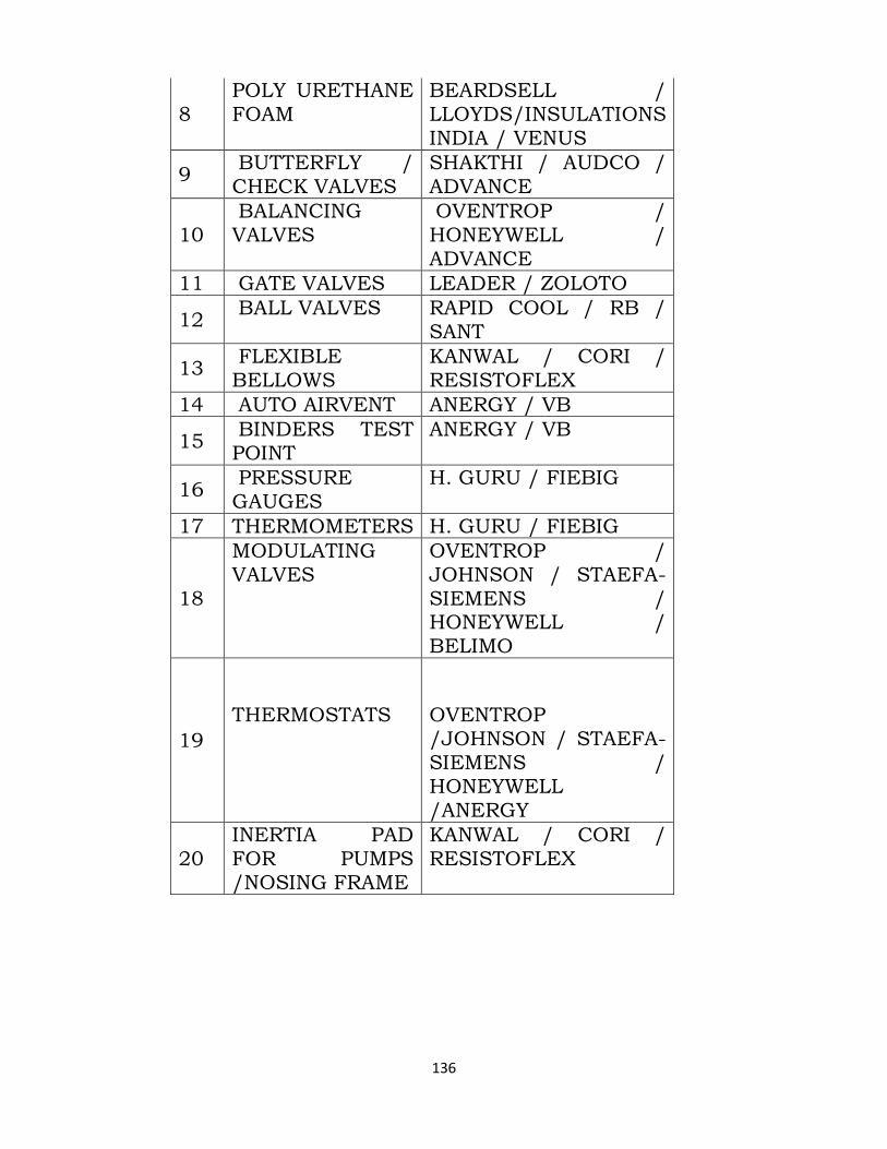
136
8 POLY URETHANE FOAM
BEARDSELL / LLOYDS/INSULATIONS INDIA / VENUS
9 BUTTERFLY / CHECK VALVES
SHAKTHI / AUDCO / ADVANCE
10 BALANCING VALVES
OVENTROP / HONEYWELL / ADVANCE
11 GATE VALVES LEADER / ZOLOTO
12 BALL VALVES RAPID COOL / RB /
SANT
13 FLEXIBLE BELLOWS
KANWAL / CORI / RESISTOFLEX
14 AUTO AIRVENT ANERGY / VB
15 BINDERS TEST POINT
ANERGY / VB
16 PRESSURE GAUGES
H. GURU / FIEBIG
17 THERMOMETERS H. GURU / FIEBIG
18
MODULATING VALVES
OVENTROP / JOHNSON / STAEFA-SIEMENS / HONEYWELL / BELIMO
19
THERMOSTATS
OVENTROP /JOHNSON / STAEFA-SIEMENS / HONEYWELL /ANERGY
20 INERTIA PAD FOR PUMPS /NOSING FRAME
KANWAL / CORI / RESISTOFLEX
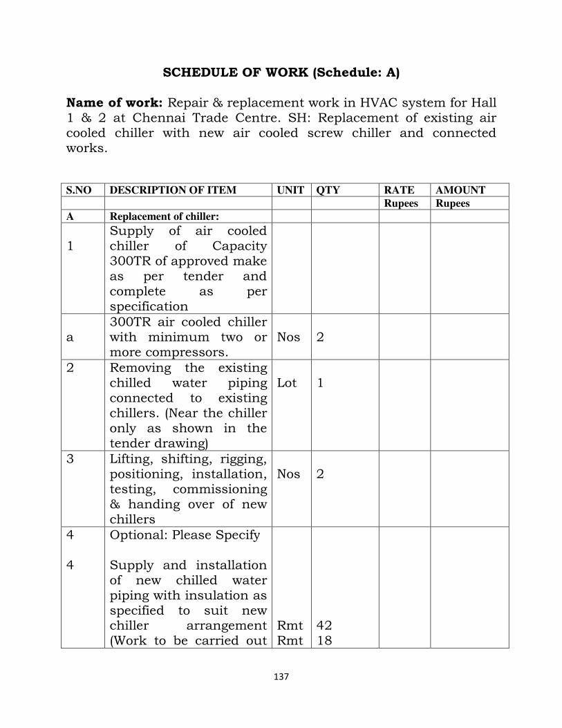
137
SCHEDULE OF WORK (Schedule: A)
Name of work: Repair & replacement work in HVAC system for Hall 1 & 2 at Chennai Trade Centre. SH: Replacement of existing air cooled chiller with new air cooled screw chiller and connected works.
S.NO DESCRIPTION OF ITEM UNIT QTY RATE AMOUNT
Rupees Rupees
A Replacement of chiller:
1
Supply of air cooled chiller of Capacity 300TR of approved make as per tender and complete as per specification
a
300TR air cooled chiller with minimum two or more compressors.
Nos
2
2 Removing the existing chilled water piping connected to existing chillers. (Near the chiller only as shown in the tender drawing)
Lot
1
3 Lifting, shifting, rigging, positioning, installation, testing, commissioning & handing over of new chillers
Nos
2
4 4
Optional: Please Specify Supply and installation of new chilled water piping with insulation as specified to suit new chiller arrangement (Work to be carried out
Rmt Rmt
42 18
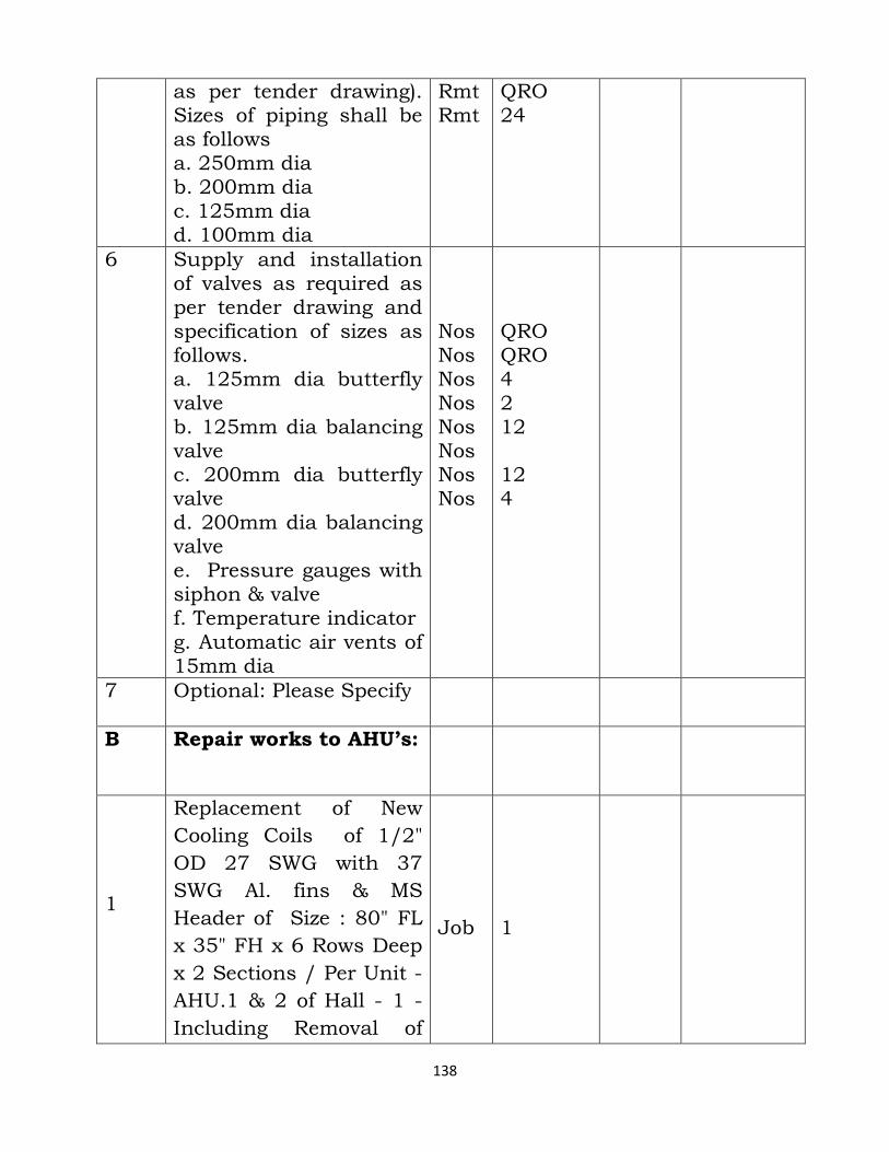
138
as per tender drawing). Sizes of piping shall be as follows a. 250mm dia b. 200mm dia c. 125mm dia d. 100mm dia
Rmt Rmt
QRO 24
6 Supply and installation of valves as required as per tender drawing and specification of sizes as follows. a. 125mm dia butterfly valve b. 125mm dia balancing valve c. 200mm dia butterfly valve d. 200mm dia balancing valve e. Pressure gauges with siphon & valve f. Temperature indicator g. Automatic air vents of 15mm dia
Nos Nos Nos Nos Nos Nos Nos Nos
QRO QRO 4 2 12 12 4
7
Optional: Please Specify
B Repair works to AHU’s:
1
Replacement of New
Cooling Coils of 1/2"
OD 27 SWG with 37
SWG Al. fins & MS
Header of Size : 80" FL
x 35" FH x 6 Rows Deep
x 2 Sections / Per Unit -
AHU.1 & 2 of Hall - 1 -
Including Removal of
Job
1
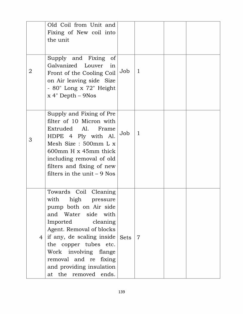
139
Old Coil from Unit and
Fixing of New coil into
the unit
2
Supply and Fixing of
Galvanized Louver in
Front of the Cooling Coil
on Air leaving side Size
- 80" Long x 72" Height
x 4" Depth – 9Nos
Job
1
3
Supply and Fixing of Pre
filter of 10 Micron with
Extruded Al. Frame
HDPE 4 Ply with Al.
Mesh Size : 500mm L x
600mm H x 45mm thick
including removal of old
filters and fixing of new
filters in the unit – 9 Nos
Job
1
4
Towards Coil Cleaning
with high pressure
pump both on Air side
and Water side with
Imported cleaning
Agent. Removal of blocks
if any, de scaling inside
the copper tubes etc.
Work involving flange
removal and re fixing
and providing insulation
at the removed ends.
Sets
7
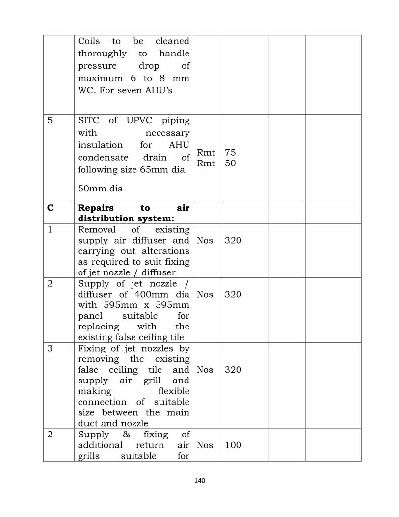
140
Coils to be cleaned
thoroughly to handle
pressure drop of
maximum 6 to 8 mm
WC. For seven AHU’s
5 SITC of UPVC piping
with necessary
insulation for AHU
condensate drain of
following size 65mm dia
50mm dia
Rmt Rmt
75 50
C Repairs to air distribution system:
1 Removal of existing supply air diffuser and carrying out alterations as required to suit fixing of jet nozzle / diffuser
Nos
320
2 Supply of jet nozzle / diffuser of 400mm dia with 595mm x 595mm panel suitable for replacing with the existing false ceiling tile
Nos
320
3 Fixing of jet nozzles by removing the existing false ceiling tile and supply air grill and making flexible connection of suitable size between the main duct and nozzle
Nos
320
2 Supply & fixing of additional return air grills suitable for
Nos
100
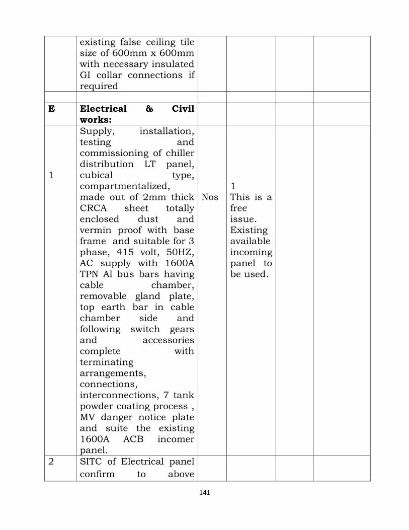
141
existing false ceiling tile size of 600mm x 600mm with necessary insulated GI collar connections if required
E Electrical & Civil works:
1
Supply, installation, testing and commissioning of chiller distribution LT panel, cubical type, compartmentalized, made out of 2mm thick CRCA sheet totally enclosed dust and vermin proof with base frame and suitable for 3 phase, 415 volt, 50HZ, AC supply with 1600A TPN Al bus bars having cable chamber, removable gland plate, top earth bar in cable chamber side and following switch gears and accessories complete with terminating arrangements, connections, interconnections, 7 tank powder coating process , MV danger notice plate and suite the existing 1600A ACB incomer panel.
Nos
1 This is a free issue. Existing available incoming panel to be used.
2 SITC of Electrical panel
confirm to above
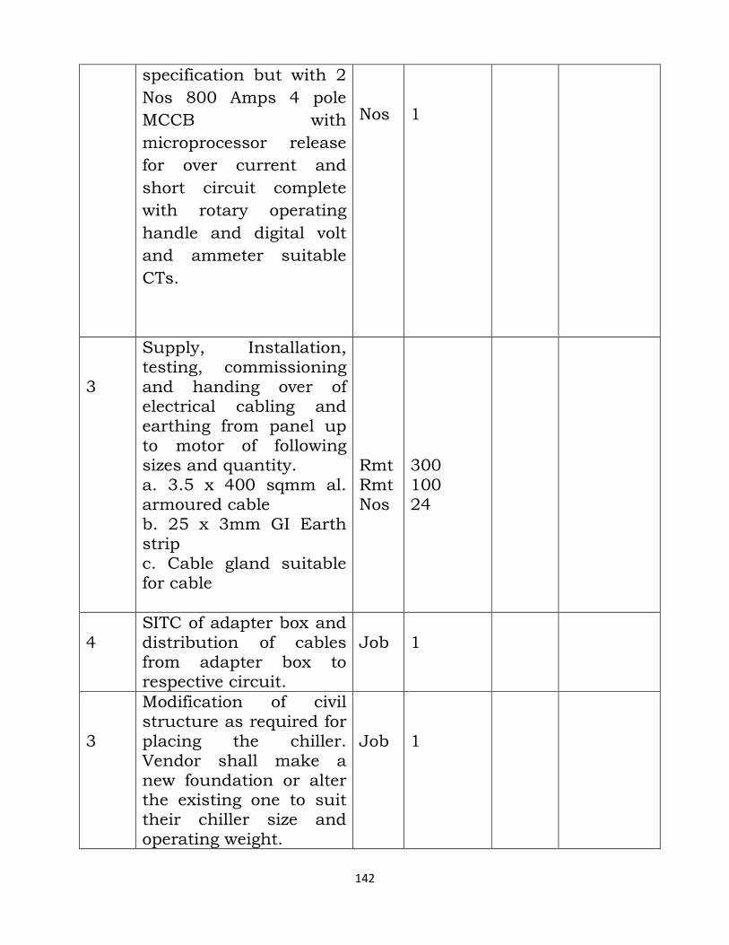
142
specification but with 2
Nos 800 Amps 4 pole
MCCB with
microprocessor release
for over current and
short circuit complete
with rotary operating
handle and digital volt
and ammeter suitable
CTs.
Nos
1
3
Supply, Installation, testing, commissioning and handing over of electrical cabling and earthing from panel up to motor of following sizes and quantity. a. 3.5 x 400 sqmm al. armoured cable b. 25 x 3mm GI Earth strip c. Cable gland suitable for cable
Rmt Rmt Nos
300 100 24
4
SITC of adapter box and distribution of cables from adapter box to respective circuit.
Job
1
3
Modification of civil structure as required for placing the chiller. Vendor shall make a new foundation or alter the existing one to suit their chiller size and operating weight.
Job
1
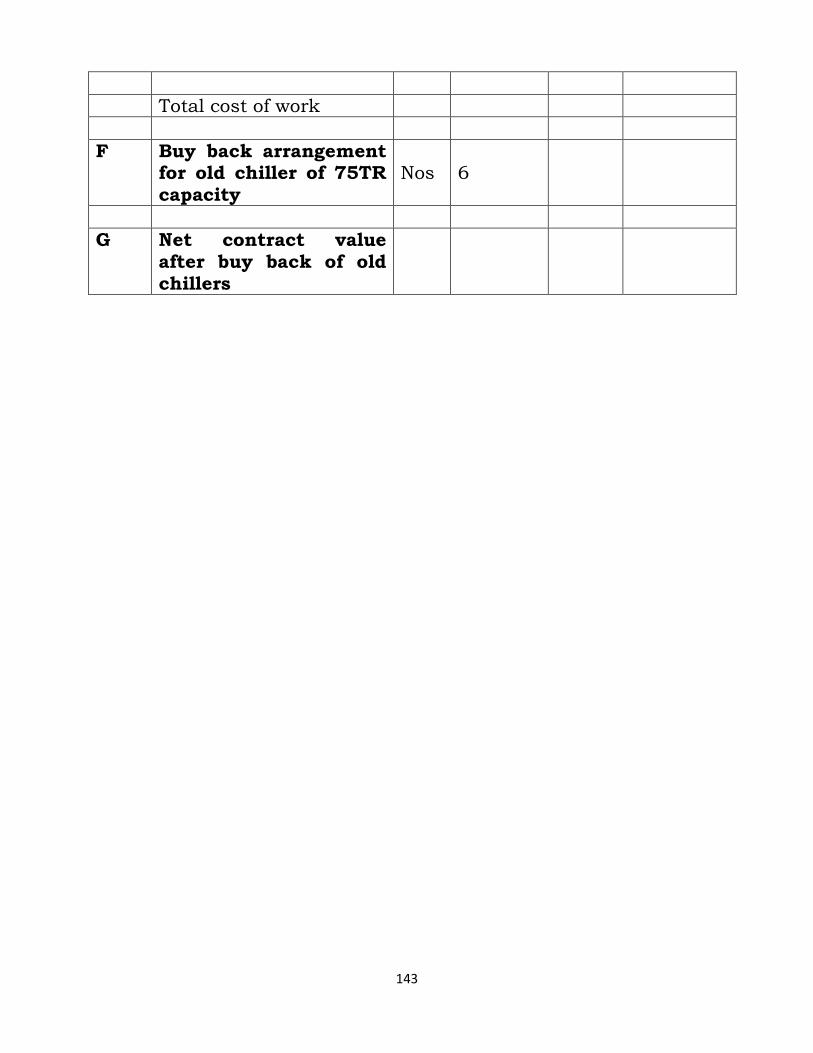
143
Total cost of work
F Buy back arrangement for old chiller of 75TR capacity
Nos
6
G Net contract value after buy back of old chillers