Embed Size (px)
Citation preview

Talbot interferometry with increased shear
Krzysztof Patorski
The modification of Talbot interferometer configuration for obtaining moire fringe shearing interferogramswith an increased shear amount is proposed. The problem of decrease of interferogram quality that occurswhen using higher frequency gratings is significantly eliminated by rotating the beam splitter grating aboutthe axis perpendicular to the grating lines. The theory of the interferometer and its experimental verifica-tion are presented.
1. Introduction
The so-called Talbot interferometer was developedat the beginning of the seventies.1-3 It belongs to thegroup of lateral shear interferometers; the diffractiongratings are used as the beam splitting and recombiningdevices. Since the interferometer consists of two dif-fraction gratings only it is very easy to align and to workwith. Originally, it was proposed for the investigationof phase objects and optical elements. Recently, theprinciple of Talbot interferometry was extended tooptical differentiation of quasi-periodic patterns, i.e.,distorted specimen gratings used in the moire methodof strain analysis. 4
The gratings used in the Talbot interferometer areof low spatial frequency typically ranging from 5 to 20lines/mm. We wanted to obtain information about thefirst derivative of the phase distribution under studyand worsening of the fringe pattern quality when theshear amount is increased. The shear value is equal tothe product z tanO, where z is the separation distancebetween two diffraction gratings (when the phase objectis placed in front of the beam splitter grating) or be-tween the phase object and the second grating (when theobject is placed between the gratings), 0 is the first-orderdiffraction angle of the beam splitter grating.
When the phase distribution under study is not largeenough the number of shearing interference fringes maynot be sufficient for the subsequent interpretation ofthe interferogram (moire fringes observed in the planeof the second grating'- 3). Therefore, it is desirable to
The author is with Warsaw Technical University, Institute of De-sign of Precise & Optical Instruments, 8 Chodkiewicza Street, 02-525Warsaw, Poland.
Received 2 March 1985.0003-6935/85/244448-06$02.00/0.© 1985 Optical Society of America.
work at increased shear. In the Talbot interferometerconfiguration this can be done by increasing the gratingseparation distance z or using higher frequency gratings.However, in both cases diffraction orders of the beamsplitter grating carrying the information about thephase object become more separated in the plane of thesecond (detection) grating. The multiple beam inter-ference of these diffraction orders does not lead to theformation of high contrast self-images of the firstgrating and, as a consequence, clear moire fringes cannotbe obtained.
In such a case the only solution is to shift from mul-tiple-beam to two-beam interference by adding thespatial filtering system3 5 (resulting in the enlargementof the experimental equipment which we try to avoid)or placing the second grating at such a distance from thefirst where the two-beam interference of the adjacentdiffraction orders is only encountered.6 In the lattercase the shear amount is equal to half of the diameterof the beam under test. By using this approach, how-ever, the observation field is greatly reduced. The wavefront under test cannot be reestablished because themeasured values are too scarce.5 7 For example, in thecase of lens testing the recommended shear amountshould be equal to 0.1 of the diameter of the exit pupil.5 7
In such a condition, however, moire shearing interfer-ence fringes cannot be obtained in the Talbot interfer-ometer setup because of the above-mentioned degradedmultiple-beam interference of diffraction orders of thefirst grating.
In this paper we present a modification of the Talbotinterferometer configuration that reduces the degra-dation of the multiple-beam interference. It will beshown that by tilting the beam splitter grating (or, al-ternatively, the detection grating) about the axis normalto the grating lines the useful moire fringes corre-sponding to the lateral shear interferogram can be ob-tained. In the same interferometer setup with thegrating untilted, clear moire fringes could not be dis-cerned. Therefore, the configuration proposed extends
4448 APPLIED OPTICS / Vol. 24, No. 24 / 15 December 1985
the range of lateral shear values permitted in the knownTalbot interferometer system. The theoretical analysiswill be given and the merits and demerits will be dis-cussed and illustrated by the experiments.
11. Analysis
Figure 1 is a schematic representation of the Talbotinterferometer setup under investigation. Let us as-sume that lens L is the lens under test. Since the pointsource S is placed at the front focal plane of L, thequasi-plane aberrated wave front illuminates the beamsplitter grating Gl. In a conventional Talbot inter-ferometer configuration grating G 1 lies in the x -y planeperpendicular to the optical z axis of the optical system,the x-y plane of detecting grating G2 (placed at a dis-tance z0 in the Fresnel region of G1) is parallel to theplane of GI. When the lines of both gratings are mu-tually parallel the moire fringes observed just behinddetecting grating G2 depict the contour map of the firstderivative of wave aberration (under the approximationof small shear value'- 3). The finite fringe detectionmode (quasi-straight fringes distorted proportionallyto the first derivative) is obtained when one of thegratings is slightly rotated about the z axis.
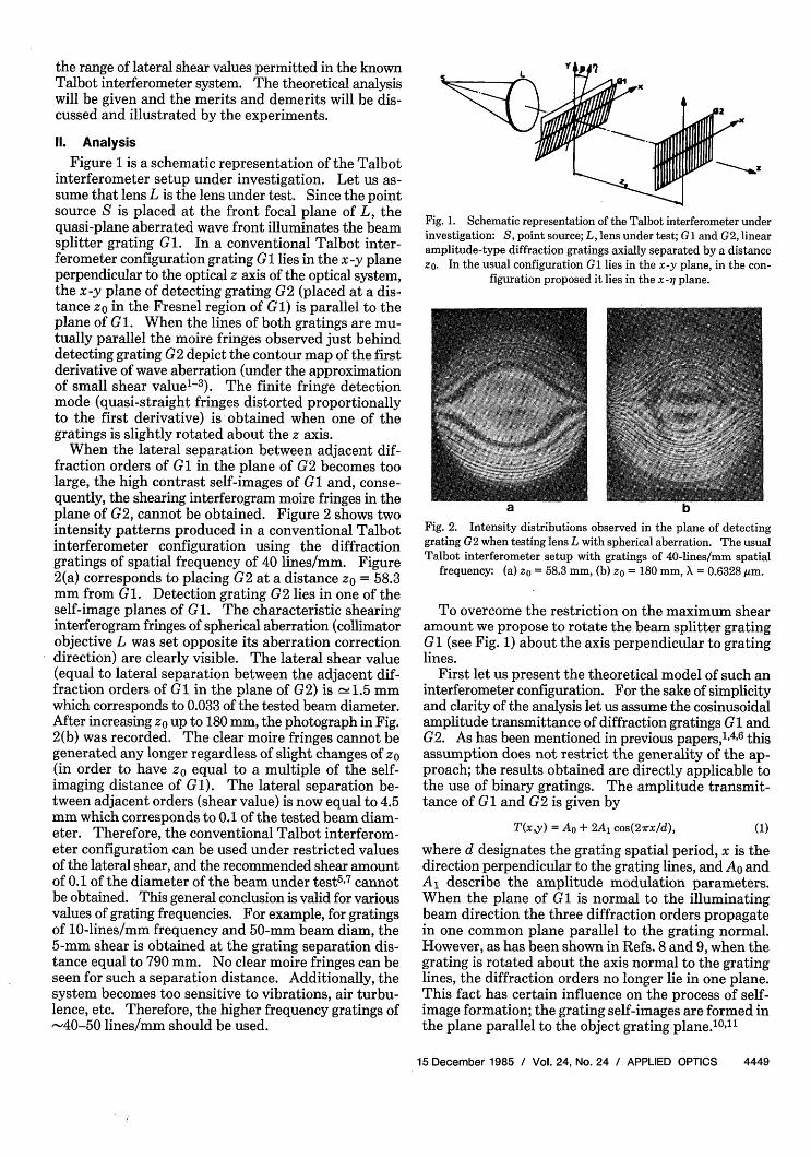
When the lateral separation between adjacent dif-fraction orders of Gl in the plane of G2 becomes toolarge, the high contrast self-images of GI and, conse-quently, the shearing interferogram moire fringes in theplane of G2, cannot be obtained. Figure 2 shows twointensity patterns produced in a conventional Talbotinterferometer configuration using the diffractiongratings of spatial frequency of 40 lines/mm. Figure2(a) corresponds to placing G2 at a distance z = 58.3mm from Gl. Detection grating G2 lies in one of theself-image planes of Gl. The characteristic shearinginterferogram fringes of spherical aberration (collimatorobjective L was set opposite its aberration correctiondirection) are clearly visible. The lateral shear value(equal to lateral separation between the adjacent dif-fraction orders of GI in the plane of G2) is 1l.5 mmwhich corresponds to 0.033 of the tested beam diameter.After increasing z up to 180 mm, the photograph in Fig.2(b) was recorded. The clear moire fringes cannot begenerated any longer regardless of slight changes of zo(in order to have z equal to a multiple of the self-imaging distance of Gl). The lateral separation be-tween adjacent orders (shear value) is now equal to 4.5mm which corresponds to 0.1 of the tested beam diam-eter. Therefore, the conventional Talbot interferom-eter configuration can be used under restricted valuesof the lateral shear, and the recommended shear amountof 0.1 of the diameter of the beam under test5 7 cannotbe obtained. This general conclusion is valid for variousvalues of grating frequencies. For example, for gratingsof 10-lines/mm frequency and 50-mm beam diam, the5-mm shear is obtained at the grating separation dis-tance equal to 790 mm. No clear moire fringes can beseen for such a separation distance. Additionally, thesystem becomes too sensitive to vibrations, air turbu-lence, etc. Therefore, the higher frequency gratings of-40-50 lines/mm should be used.
Fig. 1. Schematic representation of the Talbot interferometer underinvestigation: S point source; L, lens under test; Gi and G2, linearamplitude-type diffraction gratings axially separated by a distancezO. In the usual configuration G1 lies in the x-y plane, in the con-
figuration proposed it lies in the x--q plane.
Fig. 2. Intensity distributions observed in the plane of detectinggrating G2 when testing lens L with spherical aberration. The usualTalbot interferometer setup with gratings of 40-lines/mm spatial
frequency: (a) z = 58.3 mm, (b) zo = 180 mm, X = 0.6328 ,m.
To overcome the restriction on the maximum shearamount we propose to rotate the beam splitter gratingG1 (see Fig. 1) about the axis perpendicular to gratinglines.
First let us present the theoretical model of such aninterferometer configuration. For the sake of simplicityand clarity of the analysis let us assume the cosinusoidalamplitude transmittance of diffraction gratings G 1 andG2. As has been mentioned in previous papers,, 4 6 thisassumption does not restrict the generality of the ap-proach; the results obtained are directly applicable tothe use of binary gratings. The amplitude transmit-tance of G1 and G2 is given by
T(x,y) = Ao + 2A1 cos(2irx/d), (1)
where d designates the grating spatial period, x is thedirection perpendicular to the grating lines, and Ao andAl describe the amplitude modulation parameters.When the plane of G1 is normal to the illuminatingbeam direction the three diffraction orders propagatein one common plane parallel to the grating normal.However, as has been shown in Refs. 8 and 9, when thegrating is rotated about the axis normal to the gratinglines, the diffraction orders no longer lie in one plane.This fact has certain influence on the process of self-image formation; the grating self-images are formed inthe plane parallel to the object grating plane.10"'1
15 December 1985 / Vol. 24, No. 24 / APPLIED OPTICS 4449

Let us investigate the complex amplitude distributionE(x,y,z) in the observation plane where the interferenceof three diffraction orders of the tilted beam splittergrating G is encountered. The grating is illuminatedby an aberrated wave front described by exp[ikg(x,y)J,where g(xy) is the OPD departure from the plane wavefront and k = 27r/X. Assuming, as is usually done in theTalbot interferometer theoretical model,-3 the slowchanges of g(x,y) with the propagation distance z wehave
E(x,y,z) = Ao exp[ikg(xy)J + Al expfik [px + qy+ g(x -A'y -) - Z(p2 + q2)/2]1+ Al expt-ik[px - qy- g(x + Ay - 6) + Z(p 2 + q 2 )/2]1, (2)
where p and q designate the propagation angles of dif-fraction orders in the x-z and y-z planes, respectively.In the configuration under discussion we have9-11
p = X/d,
q = sinf3 cos[1 -v/1-(p/cos)2], (3)
where j3 is the rotation angle of the beam splitter grating(Fig 1), A and describe the lateral shifts of 1 dif-fraction orders with respect to the zero-order beam inthe x and y directions, respectively, A = z tanp, 5 = ztanq. It is seen from Fig. 1 that z = zo - y tanB whichimplies that the parameters A and 5 are not constant inthe observation field; they vary along the y direction.The importance of this fact will be discussed in detailin the following.
The intensity distribution in the observation planeis calculated from Eq. (2) as
I(x,y,z) = Ao + 2A2 + 2A0A1 cosk [px + qy- ag(xy) A0 1 1. Ox-g(xy) 6 Z(p 2 + q2)/2] + 2A0A1 cosk x - qy
- g(x,y) A + 9g(xy) 6 + Z(p2 + q2)/2]ax ay
+ 2A2 ck [2px-2/g(xy - 5)+ 2A1 cosk 12px - 2AI
Equationtion
= A2 + 2A 2+ 4AoA, cosk [qy- g(xy)6
- Z(p 2 + q2)/2]* cosk [x g(xy) A]
+ 2A 2cosk 2px-2A g(xy - ) (4)
(4) has been derived under the approxima-
g(xy)-g(x_ y_ = dg(x,y) + O dg(x,y) (5)Ox ay
i.e., approximating the slowly varying function g(x,y)by its Taylor series expansion up to the first term. Thisis usually done in Talbot interferometry analyses.
To find the properties of the Fresnel diffraction fieldit is enough to discuss the fundamental (first harmonic)term of the intensity distribution. The term cosk [px- Aag(xy)/ax] describes a quasi-periodic intensity
pattern of period d along the x direction, the departureof intensity lines from straightness is proportional toAag(x,y)/ax. This is the basis of Talbot interferometeroperation in which the information about ag(x,y)/ax isobtained in the form of moire fringes observed just be-hind the detection grating G2. However, in the con-figuration under discussion, the amplitude of the fun-damental is modulated by the term 4AOAI cosk [qy -
ag(X'y)ay - Z(p2 + q2)/2]. It disturbs the moirefringe pattern carrying the information about8g(x,y)/lx. This character of the moire fringe patternis pertinent to the sum-type fringe formation clearlyseen from Eq. (4).
To obtain the useful moire fringe pattern we proposeto rotate slightly the detecting grating G2 about the zaxis instead of setting its lines parallel to the lines of thebeam-splitter grating G. The angular setting of thelines of G2 can be inferred from the first form of Eq. (4).To obtain a good contrast, product-type moire patternit is self-suggesting to set the lines of G2 parallel to theintensity lines of one of the two composite two-beaminterference patterns. The latter ones are formed bythe 0 and +1 or 0 and -1 diffraction orders of the tiltedbeam-splitter grating G 1 [see Ref. 10 and the first formof Eq. (4)]. The rotated detecting grating G2 can bedescribed by
IG2(X,Y) = Ao + 2A1 cos(27r/d)(x cosep ± y singp), (6)
where d is the spatial period (gratings G and G2 areidentical), so is the rotation angle, and the sign in frontof the y sin, relates to the rotation direction. In ourcase we have tangp = ± q/p.
Before conducting further the theoretical investiga-tions let us introduce some assumptions that will sig-nificantly simplify the analytical calculations. Whenusing the gratings of spatial frequency of 40 lines/mm(20- and 40-line/mm gratings of binary type are com-mercially available and suggested for the techniquediscussed here) and the tilt angles f of, for example, 45and 650, we have s = 0.7250 and s° = 1.556°, respec-tively. Additionally, it is to be noted that the spatialperiod of the above mentioned composite two-beaminterference patterns is equal to X/(p2 + q2 )1/2, whatamounts, under the experimental conditions mentioned,to 24.998 and 24.991 ,m for the tilt angles 45 and 650,respectively. The period of G2 is d = 25 m. There-fore, when the plane beam illuminates the grating in-terferometer and the detecting grating G2 is appro-prately rotated as explained above, the reference moirefringes of the spacing of 311.2 and 67.77 mm, respec-tively, will be formed. These values suggest, therefore,that for simplicity of calculation we can assume thedescription of the rotated detecting grating G2 in theform
IG2(XY) AO + 2A, cosk(px ± qy), (6a)
instead of Eq. (6)When the intensity distribution pattern expressed
by Eq. (4) is multiplied by the detecting grating functionAo + 2A, cosk (px + qy) the lowest frequency termsdescribing the moire fringes become
4450 APPLIED OPTICS / Vol. 24, No. 24 / 15 December 1985

IM(X'YZ) (AO + 2A)Ao + 2AoAl cosk g( -) A
+ g (xy) + Z(p2 + q2)/2 + cosk[2qy + g(xy) Aax qI Iq ax
-g(xy) z(p2+q2)/2 (7)ay
In the case of the detecting grating G2 rotated in theopposite direction, i.e., described by AO + 2A1 cosk (px- qy), we obtain
IM(xyz) (A2 + 2A2)Ao + 2AoAlcosk[9g( y) A0 1 11 [ -~ax Og(xy) Z(p2 + q2)/2] + cosk 2qy- d A
(5 y qP2 O2x/2 (8)Oy~ ~ ~~ayD
It follows from Eq. (7), or Eq. (8), that two moire pat-terns are seen simultaneously. The first one carries theinformation about Aag(x,y)/xx- ag(x,y)/ay. How-ever, because in the configuration under discussion A>> , we can disregard the term 9g(xy)/y up to a verygood approximation. Therefore, the first moire fringepattern depicts the first derivative of the phase distri-bution under the infinite fringe detection mode. On theother hand, the second cosine term in Eqs. (7) and (8)corresponds to the finite fringe display of 3g(x,y)/Ox.The reference carrier fringes of the spatial period X/2qrun perpendicularly to the y direction, i.e., to the gratinglines. The two moire fringe patterns are independentlypresent. The disadvantage of the intensity distributionof the sum-type moire fringes obtained when the linesof the gratings G and G2 are set parallel [see the dis-cussion of Eq. (4)] is no longer present.
In our configuration, contrary to previously describedsystems,'-6 the shear amount A is not uniform over theobservation plane because of the rotation of the beam-splitter grating G 1. This is a disadvantage of the con-figuration proposed, but the profits gained from therotation of G are more significant. The linear changeof the shear value along the y direction can be taken intoaccount when quantitatively analyzing the moire in-terferogram. Alternatively, when using the configu-ration proposed for qualitative testing and providingz0 is at least a few times larger than D sin:3 (D designatesthe diameter of the illuminating beam), the influenceof the nonuniform shear amount A with the coordinatey can be neglected (see the discussion of the experi-mental results).
The very important conclusion following from theabove discussion is that by changing the rotation angle3 of the beam-splitter grating we can adjust the periodof the cosk[2qy + Adg(x,y)/ax - Z(p2 + q 2)/2] moirefringes so that the information about the spatial de-rivative ag(x,y)/ax (or generally the shearing interfer-ogram) can be discerned. The fact that these finiteperiod moire fringes run parallel to the shear directionx helps in this matter.
In the theoretical analysis presented above we haveproved that by tilting the beam-splitter grating in the
d
Fig. 3. Intensity distributions observed in the plane of detectinggrating G2 for beam splitter grating Gi rotated about the x axis: (a)
3 = 450, (b) = 650.
Talbot interferometer about the axis perpendicular tograting lines, the range of shear values can be increasedsignificantly. Moreover, as follows from Eqs. (7) and(8), the continuous change of grating separation dis-tance zo does not influence the quality of lateral shearinterference fringes. The only effect is the phase shiftof the moire fringes, whereas the overall quality of theinterferogram remains unchanged. This property issignificantly different from the property of the con-ventional Talbot interferometer configuration.-There the longitudinal shift of one of the gratings alongthe z axis influences the contrast of the whole inter-ference (moire) field because of the self-imaging effectencountered.
The analytical investigations presented concern themodified Talbot interferometer setup with grating G 1rotated about the x axis. It is a matter of course thatthe same results are obtained when tilting the detectinggrating G2 while the beam splitter grating G remainsperpendicular to the optical axis.
111. Experimental Work
The experimental setup shown in Fig. 1 was used.Ronchi-type amplitude gratings of 40-lines/mm spatialfrequency were separated by a distance z0 = 180 mm,He-Ne laser illumination was used. In such conditionsthe intensity pattern observed just behind the detectinggrating G2 is shown in Fig. 2(b). Next, grating G wasrotated about the x axis, and grating G2 was slightlyrotated about the z axis [see Eq. (6)]. Figure 3 showsthe intensity distribution in the plane of G2 for twovalues of the inclination angle . The shearing inter-ference moire fringes cosk [Aag(x,y)/Ox + z(p 2 + q 2 )/2]are seen. They are crossed by the other moire fringescorresponding to the term cosk [2qy + Aag(x,y)/x -z(p 2 + q2)/2]. As follows from Eq. (7), the intensitypatterns shown in Fig. 3 represent the two simulta-neously present product-type moire fringes. Thechange of tilt angle influences the separation distancebetween the carrier fringes in the second moire pat-tern.
In Fig. 3(a) the shear amount A changes from 4.1 to5 mm and in Fig. 3(b) from 4 to 5.1 mm in the observa-tion field (from left to right). The average shear for the
15 December 1985 / Vol. 24, No. 24 / APPLIED OPTICS 4451
u

diameter passing through the x -z plane is 4.56 mm inboth cases. As can be noted from both photographs, thelinear change of shear can be neglected in the case ofqualitative testing (for example, for the fast lens selec-tion). However, for quantitative control the linearchange of shear over the observation field should betaken into account.
It is seen from Figs. 1 and 3 that, when increasing thetilt angle , the lateral dimension of the rotated gratinginfluences the diameter of the observation field. In ourexperiments we used 50- X 50-mm gratings for testingthe 45-mm beam diameter. It follows, therefore, thatthe method requires one diffraction grating of dimen-sions appropriately larger than the diameter of the beamunder test.
The photographs in Fig, 3 correspond to the infinitefringe detection mode in the first moire pattern de-scribed by the term cosk [/g(x,y)/Ox + z(p 2 + q2)/2].A slight rotation of G2 about the z axis results in thefinite fringe detection mode (Fig. 4).
During the experiment it was noted that moire fringepatterns similar to the ones shown in Figs. 3 and 4 canbe obtained several times when rotating the detectiongrating G2 (in clockwise and counterclockwise directionstarting from the position of parallel setting of the G 1and G2 lines). In this paper we limit ourselves to theheuristic explanation only. The origin of the effectobserved lies in the distribution of spatial beatfrequencies formed by both gratings. These beats canbe displayed in the Fourier plane of the double dif-fraction system G 1-G2 as shown in Fig. 5. The pho-tographs were taken in the back focal plane of the lensplaced behind grating G2. Figure 5(b) shows an en-largement of the first order of double diffraction. Dueto the spatial beat phenomenon occurring between thespatial frequencies of G (located on the second-ordercurve8 -10 ) and G2 (lying on the straight line along thex axis), several beat frequencies in each double dif-fraction order along the vertical direction are formed.By rotating G2 its fundamental frequency interactssuccessively with the above-mentioned beat frequencies(slightly changing their localization with the rotationof G2). In this way several moire fringe patterns aregenerated. It must be emphasized that the effect underdiscussion is observed when using binary diffractiongratings. It is absent when the cosinusoidal transmit-tance rulings are employed. Higher diffraction orderscharacteristic of binary gratings form the spatial beatfrequencies shown in Fig. 5(b). They are responsiblefor creating several moire fringe shearing interferograms(Figs. 3 and 4) when rotating one of the gratings.
IV. Conclusions
In our investigations we aimed at development of aTalbot interferometer configuration giving the lateralshear interferograms with shears of the order of 0.1 orlarger of the diameter of the beam under test. Such ashear value is presupposed for good establishment of thewave front being analyzed.5 ' 7 In a conventional Talbotinterferometer setup much smaller shears are allowed.Otherwise, the self-images of the first grating are much
a D
Fig. 4. Finite fringe detection mode with grating G2 slightly rotatedabout the z axis: (a) # = 450, (b) 3 = 65°.
a
bFig. 5. Fourier spectrum of the double grating system G1-G2 (withG1 rotated about the axis perpendicular to the grating lines): (a)overall view, (b) enlarged part of the first order of double
diffraction.
too distorted and of low contrast. In consequence, themoire fringes needed to give the desired information inthe plane of second grating (parallel to the first one)cannot be obtained.
We have proposed to rotate one of the gratings aboutthe axis perpendicular to its lines. In this way usefulshearing interferogram moire fringes are obtained.Two fringe patterns are simultaneously present. Theycorrespond to the infinite and finite fringe display mode.By adjusting the grating tilt angle the period of one ofthe moire patterns (finite fringe detection mode) canbe properly chosen to obtain comfortable observation.The shear value varies linearly in the observation fieldin the direction parallel to the grating lines. This effectcan be taken into account during the quantitative tests
4452 APPLIED OPTICS / Vol. 24, No. 24 / 15 December 1985
or neglected in the qualitative tests. The shear amountcan be changed in a continuous way by changing thegrating separation distance without impairing the moireinterferogram quality. This property, as well as theincrease in shear value, represents the advantage of theproposed configuration over the conventional Talbotinterferometer configuration.
The above-mentioned characteristics of the inter-ferometer performance derived from the theoreticalcalculations have been verified in full by the experi-ments.
The paper extends the applications of Talbot inter-ferometry and can be treated as a further contributionto the theory and applications of the self-imaging phe-nomenon.
References1. S. Yokozeki and T. Suzuki, "Shearing Interferometer Using the
Grating as the Beam Splitter," Appl. Opt. 10, 1575 (1971).2. A. W. Lohmann and D. E. Silva, "An Interferometer Based on the
Talbot Effect," Opt. Commun. 2, 413 (1971).
3. D. E. Silva, "Talbot Interferometer for Radial and Lateral De-rivatives," Appl. Opt. 11, 2613 (1972).
4. K. Patorski and D. Szwaykowski, "Optical Differentiation ofQuasi-periodic Patterns using Talbot Interferometry," Opt. Acta31, 23 (1984).
5. J. Schwider, "Single Sideband Ronchi Test," Appl. Opt. 20, 2635(1981).
6. K. Patorski, S. Yokozeki, and T. Suzuki, "Collimation Test byDouble Grating Shearing Interferometer," Appl. Opt. 15, 1234(1976).
7. B. R. Hunt, "Matrix Formulation of the Reconstruction of PhaseValues from Phase Differences," J. Opt. Soc. Am. 69, 393(1979).
8. S. Ganci, "Fourier Diffraction through a Tilted Slit," Eur. J. Phys.2, 158 (1981).
9. K. Patorski, "Fraunhofer Diffraction Patterns of Tilted PlanarObjects," Opt. Acta 30, 673 (1983); "Errata," Opt. Acta 31, 147(1984).
10. K. Patorski, "Fresnel Diffraction Field (self-imaging) of ObliquelyIlluminated Linear Diffraction Gratings," Optik 69, 30 (1984).
11. P. Bialobrzeski and K. Patorski, "Self-imaging Phenomenon ofTilted Linear Periodic Objects," Opt. Appl. 15, 000 (1985), inpress.
12. K. Patorski and P. Szwaykowski, "Producing and Testing BinaryAmplitude Gratings using a Self-imaging and Double ExposureTechnique," Opt. Laser Technol. 15, 316 (1983).
Meetings continued from page 4374
1985December
19-24 Optoelectronic & Laser Applications in Science & Engi-neering Symp., Los Angeles SPIE, P.O. Box 10, Bel-lingham, Wash. 98227
10-12 Fiber Optic Communications course, Tempe Ctr. forProf. Dev., Coll. of Eng. & Applied Sciences, AZ StateU., Tempe, AZ 85287
11 D25-2 Colorimeter Service course, Reston Hunterlab.,11495 Sunset Hills Rd., Reston, VA 22090
1986
? 3rd Int. Conf. on Metal-Organic Vapor Phase Epitaxy,Pasadena N. Bottka, Naval Res. Lab., ElectronicMaterial Tech. Branch, Wash., D.C. 20375
January
6-8 Fiber Optics Workshop & Lab., Lake Buena Vista V.Amico, Central Florida U., Coll. of Extended Studies,Orlando, FL
6-17 Optical Science & Engineering course, Tucson P.Slater, P.O. Box 18667, Tucson, AZ 85731
8-10 Detection of Optical Radiation course, Lake Buena Vis-ta V. Amico, U. of Central FL, Coll. of ExtendedStudies, Orlando, FL 32816
13-18 Optical/Optoelectronic Engineering Update Series,Week One, Los Angeles SPIE, P.O. Box 10, Belling-ham, WA 98227
19-24 Optical/Optoelectronic Engineering Update Series,Week Two, Los Angeles SPIE, P.O. Box 10, Belling-ham, WA 98227
22-23 Regional Color & Appearance course, PhiladelphiaHunterlab., 11495 Sunset Hills Rd., Reston, VA22090
27-29 Optical Gauging & Inspection course, Houston LaserInst. of Amer., 5151 Monroe St., Toledo, OH 43623
29-31 33rd Ann. Conf. Western Spectroscopy Assoc., PacificGrove D. Saperstein, IBM, E42/13, 5600 Cottle Rd.,San Jose, CA 95193
February
2-7 Int. Conf. on Picture Archiving & Communication Sys-tems for Medical Applications, Newport BeachSPIE, P.O. Box 10, Bellingham, Wash. 98227
2-7 Medicine XIV: Medical Image Production, Processing,& Display, Newport Beach SPIE, P.O. Box 10, Bel-lingham, Wash. 98227
5 D25-9 Colorimeter Service course, Reston Hunterlab.,11495 Sunset Hills Rd., Reston, VA 22090
5-6 Regional Color & Appearance course, Seattle Hunter-lab., 11495 Sunset Hills Rd., Reston, VA 22090
9-15 Astronomical Instrumentation Conf., Tucson SPIE,P.O. Box 10, Bellingham, Wash. 98227
9-15 Instrumentation in Astronomy VI Conf., Tucson SPIE,P.O. Box 10, Bellingham, Wash. 98227
continued on page 4492
15 December 1985 / Vol. 24, No. 24 / APPLIED OPTICS 4453