Embed Size (px)
Citation preview
Tailoring Deactivation & Decommissioning
Engineering/Design Activities
to the
Requirements of DOE Order 413.3A
Volume II
Prepared By
U.S. Department of Energy
Office of Environmental Management
Office of Deactivation and Decommissioning
and Facility Engineering, EM-44
Revision 1
8/11/2010
Tailoring D&D Engineering/Design to the Requirements of DOE O 413.3A
II-i
Volume II Contents
II - 1. D&D Project Activities Requiring Engineering/Design ......................................................... 3
Activity #1 Alternatives Analyses and Selection .................................................................................. 4 Activity #2 Deactivation End State and End Points.............................................................................. 6 Activity #3 Post-D&D Surveillance & Maintenance ............................................................................ 9
Activity #4 Process System Deactivation and Isolation ..................................................................... 11
Activity #5 End Points for Operable and Mothballed Systems and Equipment ................................. 13 Activity #6 Nuclear Safety Analysis................................................................................................... 15
Activity #7 Facility Condition Assessment......................................................................................... 17 Activity #8 Characterization of SSCs and Process Materials to be Disposed as Waste ..................... 19
Activity #9 Characterization for Compliance ..................................................................................... 21
Activity #10 Equipment Dismantlement and Removal ...................................................................... 23
Activity #11 Size Reduction ............................................................................................................... 27
Activity #12 Liquid Flush and Drain .................................................................................................. 29 Activity #13 Surface Decontamination ............................................................................................... 32
Activity #14 Fixative Application....................................................................................................... 34 Activity #15 Mockups......................................................................................................................... 36
Activity #16 Technology Application................................................................................................. 38
Activity #17 Shielding ........................................................................................................................ 40 Activity #18 Building Structural Integrity .......................................................................................... 42
Activity #19 Temporary Electrical Service......................................................................................... 44 Activity #20 Replacement Electrical .................................................................................................. 45
Activity #21 Ventilation Modifications .............................................................................................. 46
Activity #22 Temporary Ventilation ................................................................................................... 48 Activity #23 Breathing Air ................................................................................................................. 50
Activity #24 Temporary Enclosures and Containments ..................................................................... 51 Activity #25 Hazards Analysis ........................................................................................................... 53
Activity #26 Hazardous Material Abatement ..................................................................................... 55
Activity #27 Liquid Waste Management ............................................................................................ 56 Activity #28 Waste Identification & Planning.................................................................................... 57
Activity #29 Waste Conditioning & Packaging .................................................................................. 59 Activity #30 Waste Staging ................................................................................................................ 61
Activity #31 Waste Transport & Disposal .......................................................................................... 62
Activity #32 Facility Isolation ............................................................................................................ 64
Activity #33 Temporary Roads and Access Ways for Heavy D&D Equipment ................................ 65
Activity #34 Temporary Water for D&D............................................................................................ 66 Activity #35 Completion Verification Survey .................................................................................... 67
Activity #36 Demolition Method and Sequence ................................................................................. 68
Activity #37 Environmental Requirements and Controls for Open Air Demolition .......................... 70 Activity #38 Site/Civil Activities During and After Final Disposition............................................... 72
Activity #39 Closure Configuration.................................................................................................... 73 Activity #40 Decommissioning End State and End Points ................................................................. 74
Activity #41 Operations and Maintenance Reduction ........................................................................ 76 Activity #42 Radiological Engineering............................................................................................... 77
Activity #43 Trade-off Studies ........................................................................................................... 79
Activity #44 Reconfigure Security Boundary..................................................................................... 80 Activity #45 Waste Treatment ............................................................................................................ 81
Activity #46 In-Situ Decommissioning Grouting/Void Fill Analysis ................................................ 83 Activity #47 In-Situ Decommissioning Cover Systems ..................................................................... 85
Activity #48 Authorization Basis Step-Out Criteria ........................................................................... 87
Tailoring D&D Engineering/Design to the Requirements of DOE O 413.3A
II-ii
II - 2. Example Lines of Inquiry ....................................................................................................... 89 II - 2.1 Lines of Inquiry for the Three Step Process Described in Volume I, Section 4 ................... 89 II - 2.2 Lines of Inquiry for Individual Engineering Activities ......................................................... 91
II - 3. Example Project..................................................................................................................... 100 II - 3.1 Example Project Description............................................................................................... 100
II - 3.2 Example Facility Description.............................................................................................. 100
II - 3.3 Example Project Significant Engineering/Design Activities .............................................. 107 II - 3.4 Example Project Lessons Learned ...................................................................................... 108
II - 3.5 Example Project Activity Sheets ......................................................................................... 109 Activity #2 – Deactivation End State and End Points....................................................................... 112
Activity #8 – Characterization of SSCs & Process Materials Likely to be Disposed as Waste ....... 114
Activity #10 – Equipment Dismantlement and Removal ................................................................. 116
Activity #11a – Size Reduction of the Glovebox Line ..................................................................... 118
Activity #11b – Size Reduction of the Reactor Tank ....................................................................... 120 Activity #15 – Mockups.................................................................................................................... 122
Activity #18 – Building Structural Integrity ..................................................................................... 123 Activity #26 – Hazardous Material Abatement ................................................................................ 124
Activity #28 – Waste Identification & Planning............................................................................... 125
Activity #36 – Demolition Method and Sequence ............................................................................ 126 Activity #42 – Hot Cell Preparation for Demolition......................................................................... 127
II - 4. Example of Input to WBS and Schedule Logic................................................................... 129 II - 4.1 Activity Title and Description ............................................................................................. 129 II - 4.2 Engineering/Design Indicators of Significance................................................................... 129
II - 4.3 Concept Development for Key Engineering/Design Deliverables...................................... 130 II - 4.4 Development of Baseline for Key Engineering/Design Deliverables ................................. 131
II - 4.5 Ready for Implementation for Key Engineering/Design Deliverables ............................... 133 II - 4.6 Schedule Relationships ....................................................................................................... 134
Volume II Tables
Table II - 1 – Example Project Facility Rooms and Spaces...................................................................... 101
Table II - 2 – Example Project Facility Process Systems and Equipment ................................................ 103 Table II - 3 – Example Project Facility Support and Service Systems and Equipment ............................ 104
Table II - 4 – Example Project Activities Bases for Significance............................................................. 109
Volume II Figures
Figure II - 1 – Example Facility Grade Floor ........................................................................................... 105
Figure II - 2 – Example Facility Basement Arrangements ....................................................................... 106
Figure II - 3 – Examples of Large Attached Equipment ........................................................................... 129 Figure II - 4 – Examples of Unattached Materials .................................................................................... 130
Figure II - 5 – WBS Concept for Equipment Dismantlement and Removal............................................. 131 Figure II - 6 – Schedule Logic for Equipment Removal Engineering ...................................................... 135
Tailoring D&D Engineering/Design to the Requirements of DOE O 413.3A
II-3
II - 1. D&D PROJECT ACTIVITIES REQUIRING ENGINEERING/DESIGN
In this Section, each of the 48 typical D&D engineering/design activities is described with information as
follows:
Purpose and Description – The descriptions here are at a fairly high level as they might be listed
in a project WBS dictionary. For baseline cost estimate and schedule creation, each would need
to be broken down into its respective subset of activities.
Engineering/Design Indicators of Significance – The intent of these indicators is to help project
teams and independent reviewers identify for a specific activity those project-significant activities
for which engineering/design must be developed in greater detail for a reliable project baseline. It
is important to identify these critical engineering/design activities early and focus the appropriate
level of resources on them.
For other activities, the BOE and the baseline can rely upon the skill and judgment of the project’s
engineers, estimators, schedulers, and project team that will be conducting the activity.
Concept Development – In the concept development phase of each activity, the engineering/
design development focuses on detailed functional requirements of what needs to be done for the
activity.
Development of Baseline – During this phase, the engineering/design advances to the additional
technical detail needed to support the project baseline. Development focuses on how the activity
is to be implemented, during which engineering/design deliverables for the activity should be
well advanced.
Ready for Implementation – represents completion of deliverables to the point needed to support
conduct of the activity in the field.
In addition to baseline development, output from these activities provides input to procurement, quality
assurance, health and safety planning, integrated safety management, work packages and procedures,
training, and other functions for project implementation.
The numbering and order of activity listing does not imply priority or operational sequence. It should be
understood that any specific project will not require all the activities in this table; and undoubtedly, some
projects will have activities that are not listed. It is the responsibility of project management to address
which apply and their importance, as discussed further under the tailoring discussion in Section 3.5 and
the process in Section 4.
Tailoring D&D Engineering/Design to the Requirements of DOE O 413.3A
II-4
Activity #1 Alternatives Analyses and Selection
The purpose of this activity is:
For decommissioning, to identify and select an approach and the decommissioning end state.
For deactivation, to decide the degree to which the facility will become be shutdown and non-
operable.
For deactivation, to decide if the deactivation effort will reduce the facility hazard category.
Description
This activity is to define, evaluate, and select alternatives for the end-state conditions of a facility or
group of facilities to be decommissioned. For CERCLA projects, these engineering activities are
conducted to support the Remedial Investigation/Feasibility Study (RI/FS) or Engineering
Evaluation/Cost Analysis (EE/CA). Evaluation can also address facility category reduction; say from
Nuclear Category 3 to a Radiological or Industrial Category to determine if efficiency of conducting
deactivation activities will be improved.
A defensible method of evaluating each alternative must be used. Typically, this requires the selection of
objective criteria (e.g., cost, effectiveness, regulator acceptance, ease of implementation, etc.) against
which each alternative is evaluated. A variety of evaluations may be used. One is called “structured
value analysis” in which weights are assigned to each criterion based on importance to success of the
project; each alternative is graded for each criterion, and the alternative compared based on the weighted
results among them. Other evaluation methods can involve a more explicit comparison using CERCLA
criteria of effectiveness, implementability, and cost.
Engineering/Design Indicators of Significance
Alternatives analysis is likely to be a significant engineering/design element of baseline development
because the selected alternative establishes the bases for project scope.
Concept Development
A set of alternatives to accomplish the end state vision for the facility should be identified. While the
range of alternatives should include all reasonable and promising choices available to decision makers, it
is normally desirable to keep the number of alternatives considered in alternatives analysis as small as
possible.
Conceptual alternatives are defined only to the level of detail necessary to explore the potential merits of
the alternatives in addressing the problems in the facility. They are defined to the level of detail
necessary to support a sufficiently reliable analysis of costs and impacts with the goal of identifying the
optimum alternative for advancement to more detailed planning in the next project phase.
For a project subject to CERCLA the EE/CA and Action Memorandum, or RI/FS and Record of Decision
(ROD), provide the selected alternative that becomes the overall technical approach for the Conceptual
Design Report (CDR). For non-CERCLA projects, creating the CDR requires developing the project’s
overall technical approach.
Several individual evaluations may be conducted to arrive at technical approach decisions for specific
field activities. Recommendations from the evaluations define the concept.
Development of Baseline
Evaluation results are used to decide how to proceed with the project and also to provide input for further
development of activities for baselining. However, creating the details for the selected alternative is
provided in the conduct of other activities.

Tailoring D&D Engineering/Design to the Requirements of DOE O 413.3A
II-5
For a CERCLA project, the activities conducted to create the Remedial Design/Remedial Action
(RD/RA) document plus other engineering/design activities provide input to the project baseline. For non-CERCLA projects, engineering/design equivalent to that needed for an RD/RA should be conducted.
Ready for Implementation
Preparation for implementation is not applicable because the results here are provided to other activities.
Tailoring D&D Engineering/Design to the Requirements of DOE O 413.3A
II-6
Activity #2 Deactivation End State and End Points
Purpose
This activity specifies the facility conditions to be achieved upon completion of a deactivation project;
these conditions include:
End state, which is a vision of the overall facility status.
End points, which are the detailed conditions to be achieved upon completion.
Description
A deactivation project for a facility that is radiologically or chemically contaminated, or contains nuclear materials or bulk chemicals should apply the end points process to define project completion, regardless of degree of the contamination or amount of materials. This activity implements guidance provided in
DOE G 430.1-3, Deactivation Implementation Guide1.
Defining the facility end state establishes the high level requirements for conditions to be achieved at
completion of a project. The end state should also address the facility disposition following project
completion; for example extended surveillance and maintenance (S&M) and/or transfer to another
organization.
The deactivation end state represents the agreed-upon facility condition that is to be achieved after
completion of the deactivation effort. This condition is the ultimate goal of deactivation and is
characterized by a safe facility configuration that can be maintained until decommissioning is feasible.
The deactivation end state vision must be determined by the project team based on the project objectives,
funding and schedule. For example, the deactivation end state vision for a particular facility could be
defined as a facility from which all process equipment has been removed and all remaining surfaces
decontaminated to unconditional release levels. On the other hand, it may be appropriate to define the
deactivation end state as a facility from which all process equipment remains in the facility but has been
cleaned of held up process materials and is mechanically and electrically isolated (e.g., via air gapping of
pipes and conduits).
Specification of detailed space-by-space and system-by-system end point conditions to be achieved
provides the requirements for the engineering/design and other work planning activities needed to
develop the project performance baseline. Typically, it is the function of facility engineers to derive and
specify end points applicable to the entire facility, which for large facilities can result in several hundred
individual end points.
The detailed specifications for, and the actual end points achieved, will vary from facility to facility.
Variations are expected because of the differences among facilities with respect to previous mission
requirements, equipment and systems, containment, degree of contamination, ability to isolate the
contamination, facility environs, projected ultimate disposition, and a host of other factors. Regardless,
the methods used to decide and specify end points are fundamentally similar.
The number of specific deactivation end points will be directly related to the facility complexity and the
scope of the deactivation project. The effort needed is dependent upon size, number of process systems
and amount of equipment, number of rooms, connection to other facilities, and others. The number of
end point specifications can range from less than 100 for a small facility with few systems, to several
hundred (or more) for a large process facility such as a canyon or reactor. In contrast, for a deactivation
project in which the scope of the project is complete cleanout of the facility, there will be very few end
points.
1 The Deactivation Guide provides additional detail on how to plan and implement the end points process.
Tailoring D&D Engineering/Design to the Requirements of DOE O 413.3A
II-7
Engineering/Design Indicators of Significance
Specifying end points is a significant engineering/design element for every deactivation project because
they ensure the conditions to be achieved at the completion of the project are explicitly stated and
understood.
Concept Development
The end state vision and functional end points should be established as a key input to the CDR. At the
concept stage, the end point specifications are functional in nature. The degree of detail should address
“what” the end points should be, but not “how” to implement them. For example, systems can be
specified as continued operable, isolated and abandoned in place, or mothballed. Spaces (rooms,
outbuildings, etc.) can be specified as access required or not during post-deactivation surveillance and
maintenance.
A comprehensive End Points Report should be created that:
Describes the overall end state of the facilities and area within scope.
Describes the surveillance and maintenance concept that will be in place when the end state is
achieved because it is a driver for developing end points (see Activity #3).
Identifies each space in the main facility, all systems, and external structures within scope.
States the criteria for end points.
Specifies the conditions to be achieved for spaces, systems, major equipments, and external
structures to meet the criteria.
Development of Baseline
For baseline development, engineering/design translates the conceptual (functionally defined) end points
into “how” they are to be implemented. Baseline development includes:
For each facility system and major equipment that is to remain operable or mothballed for future
use:
o If end points involve a change in physical configuration, a design change package should be
engineered that includes marked up drawings, specification of components and materials, fabrication details, and installation requirements. An example of reconfiguration might be cascading a ventilation system in a large facility to fewer stacks; Activity #21, Ventilation Modifications would apply. See Activity #5.
o If end points involve a change in operation mode, with or without physical changes, the new
modes should be described so that the baseline can include the schedule and an estimate of the testing and operations to validate the new mode. Changes to the operations procedures and other documents may be deferred to the implementation stage. An example of operational mode change would be running a ventilation system in exhaust mode at a lower flow rate with the supply fans not operating; Activity #21, Ventilation Modifications would apply. See Activity #5.
o If there is no substantial change in physical configuration or operation mode, no further detail
is needed.
For each facility system and major equipment that is to be permanently isolated, either of two
cases might apply:
o There is a standard procedure; it is sufficient to state the procedure. For example, if the
electrical feed to a building is to be gapped, and a procedure exists for electrical gapping, it is
Tailoring D&D Engineering/Design to the Requirements of DOE O 413.3A
II-8
sufficient to refer to the procedure and rely on experience and judgment for the baseline
activity.
o There is no standard procedure; installation requirements for the isolation method must be
designed and specified for each location and can include engineering/design sketches, drawings, marked up photographs, and specification of components and materials for isolation devices. See Activities #4 and #32.
For the facility interior spaces and rooms, and exterior buildings and structures:
o For which access will be required for periodic S&M, describe modifications or additions, if any, to ensure safety of personnel considering the changed mode of the facility in its deactivated state.
o For which routine access will not be required, describe modifications or additions, if any, to
prevent inadvertent entry.
Field investigation will be needed prior to CD-1 to provide information to develop the designs and
specifications.
Ready for Implementation
Implementation of end points requires completion of design change packages and the development of
detailed work packages and/or procedures. For end points that are complex or require long lead time,
these activities should be substantially completed by CD-3. However, for end points that are relative
straightforward to implement, work package and procedure development may occur after CD-3 with
sufficient lead time for implementation.
Tailoring D&D Engineering/Design to the Requirements of DOE O 413.3A
II-9
Activity #3 Post-D&D Surveillance & Maintenance
For deactivation projects the purpose of this activity is to:
Layout the details of the deactivation activities for cases in which deactivation is to be followed
by an extended S&M period.
Provide input to deactivation end points for which conditions are to be established to support
post-deactivation S&M.
For decommissioning projects the purpose of this activity is to provide input for establishing physical
conditions for activities that will be conducted after decommissioning is completed. This provides input
to Long-Term Stewardship (LTS), where applicable.
Description
For deactivation projects this activity evaluates the S&M to be conducted after project completion.
Depending on the scope of deactivation, evaluating the S&M needs can include identifying:
Walk-through paths.
Health and safety requirements for entry.
Inspections for water in-leakage, animal intrusion, degraded structural conditions, hazards to
workers conducting S&M, and other physical conditions of the building.
Monitoring and maintaining equipment and systems that remain operational.
This activity applies to deactivation projects that place a facility in a monitored storage mode and for
which an extended period of surveillance and maintenance is anticipated. For deactivation that is directly
followed by demolition, S&M input to deactivation planning becomes moot.
The reason this planning is needed relatively early is because it provides input to the end-point conditions
of systems and spaces within the facility. The procedures for implementing the S&M plan may not be
needed until deactivation is complete; that is, prior to CD-4.
The S&M program should attempt to minimize the need for entry. Material security and safeguards may
be another consideration. Facilities that house high-value or classified material will require safeguards
and security measures. Situations requiring such measures should be reviewed with the goal of removing
or otherwise eliminating the causative factors. Another primary area of concern is roof integrity, an
essential element of maintaining the safety perimeter of the facility. Periodic attention to the condition of
the roofing and possible repair may be necessary. It should be noted that events involving facility roofs
(e.g., personnel falling through or water damage to equipment) have occurred periodically across the
DOE complex, but may have been preventable with adequate inspection and evaluation.
For decommissioning projects, this activity requires understanding what the end state and follow-on
activities will be (see Activity # 40). In a case of a green field end state, there may be no subsequent
surveillance. In a case of Office of Legacy Management responsibility or institutional control of the site
by the DOE, there may be monitoring requirements (or a decision that there are none) that could affect an
interim or final configuration per the CERCLA Record of Decision.
Engineering/Design Indicators of Significance
Post-D&D surveillance & maintenance is not likely to require detailed engineering/design deliverables for
the baseline because only the functional level of S&M planning is needed for input to end points planning
prior to CD-3.
Detailed S&M procedures need to be developed prior to CD-4.
Tailoring D&D Engineering/Design to the Requirements of DOE O 413.3A
II-10
Concept Development
The deliverable for concept development should be a high level plan that addresses the points in the
above description of this activity. Again, the purpose of this plan is to support end points development.
Development of Baseline
To produce the baseline, the work to develop the post-deactivation S&M procedures must be incorporated
in the project baseline. This may be a specific activity for a large-complex facility; otherwise the effort
can be encompassed within level-of-effort engineering support for the project.
Ready for Implementation
Beyond baseline development, there is no need for further development at CD-3. An S&M program must
be functioning at the completion of the project. Therefore, development of a detailed plan and
implementing procedures must be complete prior to CD-4.
Tailoring D&D Engineering/Design to the Requirements of DOE O 413.3A
II-11
Activity #4 Process System Deactivation and Isolation
This activity establishes the configuration for systems and equipment to be permanently shut down.
Description
Process system deactivation is accomplished by shutting down, isolating, and establishing individual
components and/or a total system in a safe configuration. This activity refers to systems within the
facility such as for ion exchange, evaporation, incineration, waste compaction, and glovebox lines for a
variety of processes. It also includes process support systems such as ventilation, sumps and drain
collection, and cooling water. Utilities and systems that originate or terminate external to the facility are
addressed in Activity #33, Building Isolation.
Reasons for permanent shutdown of process components/systems include:
Reducing or eliminating the need for facility-specific knowledge of how to operate non-
conventional equipment and processes.
Safety of D&D workers by reducing operating equipment, eliminating energetic sources (e.g.,
voltage, pressure, coiled springs), and reducing potential exposure to hazardous chemicals and
radioactive sources.
Reducing the overall operations and maintenance (O&M) resources needed.
Engineering/Design Indicators of Significance
Shutting down and isolating process systems is likely to be a significant engineering/design element of
the project when there are more than two or three such systems.
Concept Development
Systems and major equipment to be shut down may be identified in Activity #2, End Points, during
deactivation planning; or otherwise may be a condition of facility transfer from an operations organization
to a D&D organization.
Definition of the conditions to be achieved should specify if the equipment /systems are to be abandoned-
in-place or removed, either partially (components) or in total.
The timing for when operational, engineering, and design details are needed is dependent on the overall
project plan. Reducing worker safety risk and eliminating the need for special operations knowledge will
most likely be an early project requirement, in which case technical detail should be available for the
baseline. Alternately, engineering activities to deactivate systems for purposes of reduced O&M burden
may occur after CD-3.
Development of Baseline
Baseline development includes:
Engineering to address operations that need to be conducted prior to shutdown and isolation.
Deliverables include:
o Listings of special nuclear materials and other nuclear sources to be removed and
specifying requirements for their disposition.
o Listings of classified equipment that must be removed.
o Detailed plans for the conduct of flushing/draining (see Activity #12, Liquid Flush and Drain) and purging/venting.
Engineering for isolation of the system/equipment. Deliverables include:
Tailoring D&D Engineering/Design to the Requirements of DOE O 413.3A
II-12
o New or marked up drawings to identify process inputs and outputs and isolation points
for the system/equipment to be isolated.
o Isolation point tabulations, marked up drawings, sketches and photographs to aid in
documentation.
o Isolation methods such as gapping of pipes and electrical conductors, blind flanging,
permanent rack-out and removal of circuit breakers and motor control centers, and others
(see the description of air gapping in Activity #32).
o Specifications for any special mechanical and electrical components needed for final
isolation, including material standards and dimensions/sizes.
o Closure requirements such as gasketing, torque, verification inspection and testing.
o Requirements for the to-be-as-left configuration of the system/equipment after isolation, including final valve and switch lineups within the system and from/to connecting system.
o Engineering for removal (see Activity #10 regarding rigging)
o Identifying document change requirements, such as to the Authorization Basis, O&M
procedures, and facility/systems configuration documents. While this task will not significantly affect the baseline, these changes should nevertheless be documented as a product of the engineering effort.
Ready for Implementation
Provide:
Technical requirement inputs for isolation and verification procedures and work packages.
Procurement specifications for materials, equipment, and services.
Tailoring D&D Engineering/Design to the Requirements of DOE O 413.3A
II-13
Activity #5 End Points for Operable and Mothballed Systems and Equipment
This activity establishes the configuration and modes of operation for equipment/systems that will remain
operable or be preserved for future use.
Description
One type of end point specifies equipment and systems that remain operable following deactivation. A
second type is for equipment and systems preserved for future use (i.e., “mothballed”).
Continued operation or laying up equipment and systems for deactivation can involve considerable
engineering if configurations and/or operating modes are to be modified in comparison with those during
the prior period of mission operations.
An example regarding equipment to remain operable relates to fire protection. A decision as to whether fire
suppression and/or detection remain active is closely linked with heating needs to prevent wet pipe systems
from freezing, which in turn relates to steam and electrical systems. Ongoing maintenance must also be
addressed. To address such a situation, a fire protection engineer must review the planned deactivated
status of the facility (fuels, ignition sources, occupancy) and develop recommendations accordingly.
Similar considerations can be given to sump pumping and waste processing equipment and systems.
In practice, mothballing equipment for anticipated future use has been very limited. The most common
example is for building cranes. Installed cranes can be of value during future activities that remove
building components, position decontamination and segmentation equipment, and handle waste products.
Depending on age and condition, decisions are needed as to whether cranes should be operated and
maintained or preserved for future use following deactivation.
Engineering/Design Indicators of Significance
Implementing end points for operable and mothballed systems and equipment is not likely to require detailed
engineering/design deliverables for the baseline because operation of these systems is well understood.
Exceptions include cases where there are many utility and service systems that will need to be
reconfigured or have their operating modes changed (e.g., exhaust ventilation that must maintain sub-
atmospheric building pressure for the near future).
Concept Development
Reviews by facility engineers are needed during end points development to decide what equipment to
keep operational or to mothball. The conclusions are incorporated in the end points plan addressed in
Activity #2. However, engineering is different from Activity #2 because of the different nature of the
work (shutdown vs. operable end points).
Development of Baseline
For equipment and systems that remain operable, or require reconfiguration, or for which the operating
mode will be changed, engineering/design deliverables include revised drawings, system design
document (SDD), and technical requirements to be incorporated in revised operating procedures.
Similarly, technical requirements should be provided for revised maintenance procedures and schedules.
Where reconfiguration or operating mode changes are needed, operation analyses should be conducted in
support of the change(s). The baseline should include an operations and maintenance (O&M) estimate.
For equipment that is to be mothballed, the preservation requirements must be specified.
For most projects, the BOE and the baseline for this activity can rely upon the skill and judgment of the
project’s engineers, estimators, schedulers, and project team that will be conducting the activity.

Tailoring D&D Engineering/Design to the Requirements of DOE O 413.3A
II-14
Ready for Implementation
Engineering/design activities that were initiated to support baseline development are completed.
Tailoring D&D Engineering/Design to the Requirements of DOE O 413.3A
II-15
Activity #6 Nuclear Safety Analysis
This activity evaluates:
Activities involving nuclear materials and safety-related SSCs.
Reducing the facility hazard category after hazard removal.
Resources needed to support nuclear safety of D&D activities.
Description
The difficulty of performing D&D in Nuclear Facilities (Hazard Category 3 or higher) is increased due to
the requirement to evaluate all proposed activities against the facility authorization basis. For example, in
some cases key safety related systems, such as the ventilation system may need to remain active during
initial D&D, until the nuclear material inventory is reduced to the point where the safety controls can be
eliminated.
It may be advantageous to plan to remove the nuclear material inventory from the facility early in the
project so the facility hazard category can be reduced below Hazard Category 3, thus eliminating nuclear
safety controls. It has been found in some cases, however, that conducting D&D in a facility with hazard
categorized as Radiological may not hold significant advantage compared with Hazard Category 3 status;
in such cases it may be cost effective to reduce to Hazard Category 3, but not to a Radiological or an
Industrial category.
This activity is related to, and often conducted in, support of Activity #48, Authorization Basis Step-Out
Criteria.
DOE-STD-1189, Integration of Safety into the Design Process, provides guidance for the nuclear safety
design.
Engineering/Design Indicators of Significance
Nuclear safety analysis is likely to be a significant engineering/design element of a project when the
facility hazard category is Hazard Category-2 or Hazard Category-3. (Note: a Hazard Category-1 facility
would not be in a D&D mode; also, it is unlikely for Category-2 facilities.)
Concept Development
At the concept development stage, it is appropriate to identify if nuclear safety is or is not an issue for the
project, or at what specific locations within the facility the presence of nuclear material will constrain
D&D activities. This is accomplished by a review of the existing Authorization Basis (A/B), inventory
reports, mass balances, and process knowledge to determine where SNM is located within systems and
equipment within the facility.
Development of Baseline
For projects where it is desirable to enact an A/B downgrade, the baseline should include:
Planning for downgrading the facility and changing the A/B, including identification of facility
systems covered in the facility authorization basis and A/B changes required to support D&D
activities.
Analyzing for inventory holdup, criticality modeling, and accident analyses for completion of a
Documented Safety Analysis in accordance with 10 CFR 830.
Evaluating characterization results (e.g., databases, tabulations, inventory reports) of the
quantities of residual SNM including the type of SNM involved, isotopes of concern, type and
number of equipment and locations where holdup is likely. This information is used to estimate
the number of nuclear criticality safety evaluations (NCSEs) and unreviewed safety questions
Tailoring D&D Engineering/Design to the Requirements of DOE O 413.3A
II-16
(USQs) that are required to support D&D activities. (As noted later, task based NCSEs and USQ evaluations to support D&D activities are typically conducted at the time when needed later
during project implementation.) The baseline needs to include an estimate the resources required
for these analyses.
Ready for Implementation
The ultimate outcome is to enact an A/B change and/or delineate any special provisions, protocols, and
procedures that will need to be incorporated into work packages for execution of the project scope.
All A/B revisions must be complete. NCSE input to design of processes to support D&D are used within
other activities as appropriate.
Many analyses will not be conducted prior to CD-3 because the work is not defined until task-specific
procedures and work packages are developed. Analyses that would typically be conducted later during
implementation include:
NCSEs for processes to support D&D, such as material stabilization and to support work
packages for removal of equipment that has residual fissile material.
USQ evaluations for review of project activities subject to the scope of the A/B.
The work documents for which these are needed cannot be prepared early because prerequisite work, such
as removal of surrounding equipment, must first be completed and the resulting physical configurations
are known.
Tailoring D&D Engineering/Design to the Requirements of DOE O 413.3A
II-17
Activity #7 Facility Condition Assessment
This activity:
Ensures the safety of personnel during D&D operations.
Determines current physical conditions for establishing the project baseline.
Description
When a facility is transitioned to D&D, the project team must assess the physical condition of the facility
with primary focus on safety of D&D personnel who will work in and around the facility. The structural
integrity of roofs, walls, floors, stairs, surrounding soils, etc. must be evaluated. Radiological safety,
industrial safety, and industrial hygiene surveys must be performed.
This early facility characterization is not intended to acquire the level of detail that will eventually be
needed to complete D&D of the facility. It is focused more on identifying personnel hazards than on
characterizing facility SSCs for disposal as waste. This more comprehensive characterization for waste
disposal will be done later. However, the chemical, radiological, and physical hazards must be identified
so that corrective actions can be specified to ensure that D&D personnel can safely perform the work.
Understanding of these hazards will be required for the job hazards analyses that will be conducted during
approval of the field work packages.
Abandoned or legacy facilities are those that ceased operation long ago and for which there is little
current operating knowledge base. For these facilities, a significant effort will likely be required to
identify and evaluate existing conditions before determining and taking appropriate actions.
Engineering/Design Indicators of Significance
Facility condition assessment is not likely to require detailed engineering/design deliverables for the
baseline because the scope is limited and methods are well understood.
Concept Development
The physical condition of the facility must be assessed by the end of this phase. This is most effectively
done by walking down the facility with a multidiscipline team shortly after it is identified for transfer to
the D&D program.
Facility, system, and hazardous material conditions are identified and documented in a report, which then
forms the basis for the actions that must be completed to allow D&D personnel to work safely in the
facility.
In summary, the objectives of the facility walkdown and associated data gathering activities are to:
Ensure that sufficient information has been collected, assembled, and analyzed to provide an
understanding of existing conditions and hazards
Identify any additional characterization needed
Identify and allocate resources needed to maintain stable and known conditions of the facility, its
systems and equipment pending disposition
Permit effective D&D planning
Minimize risk to project baseline cost and schedule due to scope increase as a result of late
discovery of unexpected conditions
Identify required stabilization (e.g., structures, materials, etc.) activities
Tailoring D&D Engineering/Design to the Requirements of DOE O 413.3A
II-18
A report should be prepared to document the results of the facility walkdown and associated activities.
The following information should be considered for inclusion in the report:
An operating history (including previous operational records) of the facility, providing the process knowledge of the nuclear and chemical materials that were handled and major upsets
(e.g., spills or leaks) and accidents that occurred.
A description of the condition of all structures, existing engineered protective barriers, and
systems installed to prevent migration of both hazardous and radioactive contamination to the
environment and that ensure the safety of workers, the public, and the environment.
A description of the nature, levels, and probable extent of the existing hazardous chemical
contamination, the radiological contamination, and direct radiation fields within and around the
facility.
An accurate and complete inventory (including associated uncertainties) of types, forms,
quantities, and locations of all special nuclear and fissionable materials.
An inventory or estimate and the locations of the remaining hazardous material, waste and
chemical inventories, and any associated uncertainty. This should include form and distribution
information.
The occupational hazards associated with the facility. This evaluation should focus on fixed
hazards.
Current radiological survey data used to:
o Identify barriers necessary to protect the public and the environment
o Define the radiological working conditions, equipment (e.g., containment, protective
clothing, etc.) or procedures that protect the worker
Development of Baseline
The facility condition assessment report should be used as a basis to identify work scope that must be
incorporated in the project baseline. For example, if the assessment identifies significant structural
deficiencies in the facility, major facility modifications may be required to allow safe entry of D&D
workers. Additionally, if the condition assessment indicates large areas of radiological contamination
with the potential to become airborne, the project baseline must include scope to provide the required
radiological monitoring and protection equipment, such as constant air monitors and breathing air supply,
as well as identifying areas where there is a potential for use of fixatives.
For most projects, the BOE and the baseline for this activity can rely upon the skill and judgment of the
project’s engineers, estimators, schedulers and project team that will be conducting the activity.
Ready for Implementation
All the actions needed to mitigate conditions identified in the condition assessment should be in place at
the end of this phase.
Tailoring D&D Engineering/Design to the Requirements of DOE O 413.3A
II-19
Activity #8 Characterization of SSCs and Process Materials to be Disposed as Waste
This activity:
Characterizes SSCs and their contents (wet and dry solids, and liquids, nuclear materials, etc.) to
provide input to waste management activities (see Activities #27 through #31).
Characterizes waste to establish waste profiles for transportation and disposal and for Waste
Acceptance Criteria (WAC) compliance.
Description
Prior to the start of full-scale D&D activities, area radiation and surface contamination surveys will be
needed to establish waste profiles for disposition planning. This characterization data also supports
development of D&D approach planning.
Early in the project, characterization/data acquisition proceeds from the general to the specific. First,
process knowledge is applied as to what operations occurred in each room of the building. This may
suggest what type of materials may still be present as contamination on room surfaces and in remaining
equipment. Where the project involves a reactor or accelerator, characterization for activated metals is
also necessary. Radiation surveys (using alpha and beta-gamma instruments) and inspections of
equipment interiors (using for example visual observation, remote camera entry, and nondestructive
examination) are then conducted. When knowledge about the composition of radioactive materials is
needed and process knowledge is not available, sampling or other in-situ techniques are conducted.
When the existence of residual nuclear materials or significant nuclear material contamination is possible (e.g., in glovebox lines), NDA methods are appropriate.
During project implementation, characterization occurs continuously to support work activity planning,
personnel protection, and waste generation/packaging. In many projects, the need for characterization
results in a comprehensive set of facilities, equipment, and analysis methods.
Engineering/Design Indicators of Significance
Characterization is likely to be a significant engineering/design element of the project when:
The facility is heavily contaminated and/or historical documentation and process knowledge of
the facility are lacking.
The facility contains large amounts of process equipment, the materials processed in the facility
were highly radioactive, fissile, reactive (e.g., shock sensitive, pyrophoric), or toxic materials are
present (e.g., RCRA metals such as mercury, lead, chromium).
The project will be generating TRU waste, which in most cases must be transported to the Waste
Isolation Pilot Plant (WIPP), and therefore must be characterized to meet stringent transportation
requirements and the WIPP WAC.
The facility processed a wide variety of materials with differing compositions, thus requiring segregation of the waste into discrete waste streams for shipping to the appropriate disposal
facility.
Concept Development
Characterization planning and D&D approach selection (Activity #1) go hand in hand. At this phase of
the project, emphasis is on understanding what is known about the facility and what “unknowns” need to
be addressed through characterization.
Creating detailed listings of the SSCs, process knowledge of their likely radiological and chemical
characteristics, and their locations to be characterized are the primary objectives of this phase for
characterization planning.
Tailoring D&D Engineering/Design to the Requirements of DOE O 413.3A
II-20
Characterization is also an important concurrent activity for waste management planning (Activity #28,
Waste Identification and Planning). Activity #28 should identify all the major SSCs, process materials,
and residues that will be removed and disposed as well as the quantities and types of waste generated
during D&D operations, including soil removed with slabs and foundations as part of demolition. This
planning will serve as the basis for waste characterization planning.
Development of Baseline
A comprehensive characterization plan should be developed to address the characterization activities for
all project activities and the resultant waste types that will be generated by these activities. The
characterization plan includes:
Gap analysis identifying what information needs to be confirmed, and what missing information
needs to be obtained,
Description of sampling methods and estimate of the number of samples to be taken from
area/items to be characterized,
Analyses to be conducted, anticipated methods and targeted analytes,
Survey methods and related scaling factors,
Laboratory facilities, on-site and off-site; if existing on-site facilities are to be used, the plan
should address functional readiness and the activities required to achieve it. (If a newly
constructed on-site laboratory facility will be used, the engineering/design review should follow
DOE O 413.3A guidance for design-build projects),
Identification of facilities and equipment for sampling and surveying (e.g., low background or
shielded areas),
Drivers for characterization such as disposal site WAC and transportation regulations.
The cost and schedule impact of executing the characterization plan is incorporated into the project
baseline for each project activity where SSCs or process materials will be removed or where waste will be
generated.
For some projects, high technology methods (e.g., remote devices) may be needed to obtain
characterization data. In such cases, characterization planning should include functional requirements and
the details conducted as Activity #16, Technology Application.
Ready for Implementation
At the end of this phase, characterization work packages should be complete and ready to work. This is
particularly important if sampling and certified lab analyses are required.
Specifications should be prepared for procurement of laboratory services, equipment, construction of on-
site facilities for sampling/surveying, and services to be provided on site.
Tailoring D&D Engineering/Design to the Requirements of DOE O 413.3A
II-21
Activity #9 Characterization for Compliance
This activity determines compliance with several regulatory requirements and commitments.
Description
Surveys and sampling will need to be conducted during the course of D&D activities for personnel
exposure management, environmental release monitoring, and to ensure clean-up standards are met. The
sampling and survey results will be used to confirm compliance with internal project and external
regulatory commitments such as:
Verifying end points have been achieved where verification is by sampling, survey, and/or
analyses.
Meeting RCRA criteria for allowable residual contamination within systems that contained
hazardous materials
Accountability for removal of nuclear material
Meeting criteria for post-demolition residual radiation and surface contamination.
See Activity #8 for characterization to support baseline development and waste management.
Possible Variations
Although the primary focus of D&D projects is with management of radiological contamination and
compliance with associated cleanup standards, certain projects may involve non-radioactive hazardous or
toxic contaminants. The sampling and analysis techniques for these constituents are somewhat different
than those for radiological contaminants. However, the approaches to characterization planning and
compliance attainment are similar. Therefore the material presented for this activity may be generically
applied for all compliance scenarios.
Engineering/Design Indicators of Significance
Characterization for compliance is likely to be a significant engineering/design element of the project
when high radiological exposure rates and/or contamination are present, RCRA materials are present, or
project activities include removal of SNM.
Concept Development
This activity develops the overall scope of resources and services needed for compliance characterization.
However, sampling and analysis is generally addressed in the BOE on an individual activity basis and not
in an integrated manner.
However, for overall project planning, decisions are needed regarding the availability of on-site resources
(technicians and labs) and off-site resources (e.g., laboratory services).
Engineering activities to support this planning involves identifying project activities and evaluating the
total magnitude of sampling, surveys, and analyses will be needed for complying with regulatory and
project requirements.
Development of Baseline
Compliance characterization planning includes:
Drivers for characterization such the criteria and protocols that depend on the types of tasks.
Sampling methods and number of samples to be taken based on likely radiological and chemical
characteristics, locations to be characterized, and established protocols (e.g., for accountability).
Analyses to be conducted, methods anticipated, and analytes targeted.
Tailoring D&D Engineering/Design to the Requirements of DOE O 413.3A
II-22
Survey methods and related scaling factors.
Laboratory facilities, on-site and off-site.
Availability of technicians for conducting surveys and taking samples.
Facilities and equipment for sampling and surveying (e.g., low background).
The number of samples and analyses are estimated and a unit cost applied for baseline development. The
cost and schedule impact of executing the characterization plan is incorporated into the project baseline.
Baseline considerations may also address:
Scope, cost, and schedule for adding on-site analysis capability.
Technology needs (e.g., remote devices) to obtain characterization data (See Activity #16,
Technology Application).
The deliverable is a plan to address the compliance characterization activities for all project tasks. The
plan should identify where Data Quality Objectives (DQO) are needed. Creation of each DQO is part of
the specific activity to which it applies.
Ready for Implementation
From an overall project perspective, specifications should be prepared for procurement of laboratory
services and equipment. Construction of additional on-site facilities for analysis is addressed as a design
and fabrication activity.
Otherwise, the technical details of sampling, surveying, and analyses for implementation are left to the
individual project activities that they support.
Tailoring D&D Engineering/Design to the Requirements of DOE O 413.3A
II-23
Activity #10 Equipment Dismantlement and Removal
This activity identifies and removes equipment to achieve the D&D end points.
Description
While it is often beneficial to leave as much equipment as possible for “demolition in place” along with
the building structure, some SSCs may need to be removed in advance of demolition for the following
reasons:
Nuclear material removal, reducing to facility source term, thus allowing a reduction in facility
hazard category
Contamination removal
Asset recovery
Scrap recycle
Component segregation to ensure conformance to disposal WAC
Security issues associated with the equipment design which result in special disposal
requirements
The inventory of accountable nuclear materials assigned to the equipment may require special
disposal
To be assayed to ensure compliance with disposal facility WAC when in-situ assay is not
acceptable
To package for transport to the disposal facility in situations where in-situ size reduction is not
possible or desirable
To be cut open for visual inspection, sampling or removal of residual process material, where
specially designed cutting equipment has been made available for this purpose
Planning includes tool selection for equipment removal and/or in-situ size reduction and removal path
selection, including possible structural modifications to facilitate removal.
It may be desirable to segregate the more highly contaminated process equipment from the less
contaminated building structure. For instance, in the situation where the facility end state was determined
to be demolition to slab, it is possible to dispose of the building debris as low level or even sanitary waste,
whereas the equipment my require disposal as a more expensive waste form, such as TRU waste.
Segregation to minimize the volume of the more expensive waste forms is good practice. This
segregation is possible after demolition, but is more difficult to execute. In the situation where in-situ
decommissioning is the final end state, it may be desirable to remove some equipment to reduce the
source term to meet performance assessment criteria.
Possible Variations
Equipment removal could involve reactor vessel removal or reactor internals disassembly. Design
considerations for removal need to take into account the size and complexity of these vessels (often
weighing several tons), and the very high radiation levels due to activation of the metallic components.
Removal is a complex undertaking since the reactor vessel is usually set in place before fabrication of the
containment structure is complete.
Equipment removal could also be shield block disassembly. Some types of process or research equipment
(i.e., accelerators) are housed within secondary, shielded enclosures (like massive interlocking concrete
blocks). In most cases, it will be necessary to disassemble and remove the shielded enclosure prior to
removal of the equipment.
Tailoring D&D Engineering/Design to the Requirements of DOE O 413.3A
II-24
Engineering/Design Indicators of Significance
Equipment dismantlement and removal is likely to be a significant engineering/design element of a
project when the project scope includes a large quantity of equipment or a large complex piece of
equipment must be removed for the reasons cited above.
Concept Development
At the project conceptual phase, identify:
Equipment that will require dismantlement and removal.
The general condition of equipment to be removed, including content (e.g., the presence of
liquids, sludge, gas), and contaminants (types and levels).
Specialized equipment requiring design to dismantle and remove the identified equipment (e.g.,
for large shield blocks, large vessels, large quantities of interconnected items, large machinery)
Preferred approach (e.g., removal in entirety or size-reduced; removal pathways, and special
handling needs)
Mockups needed for dismantlement/disassembly planning and craft training (see activity #15).
3D Computer modeling needed for removal planning and identification of interferences along
removal/transport pathway.
Development of Baseline
Baseline development includes:
Engineering for disconnection of the equipment from the system/facility where it is located. This
includes addressing electrical connections (e.g., power supply and I&C) and mechanical
connections (e.g., process flow, compressed air, service or cooling water). Disconnection from
equipment pedestals and foundations should also be addressed. Deliverables include:
o Work scope for disconnection
o Marked-up drawings identifying disconnection locations
o Specifications for how each location is to be physically terminated and isolated from it’s source
o Test requirements for integrity of terminations and closures
Engineering (as needed) for draining equipment prior to removal. Tap and drain operations are
further addressed in Activity #12. Deliverable related to equipment draining prior to removal
include:
o Identification of drain location
o Identification of liquid/sludge removal method
o Collection method
o Marked-up drawings identifying drain location(s)
Engineering for dismantlement/disassembly of the equipment to facilitate removal (or provide
access to internals for decontamination or removal of residuals). This includes addressing at a
component level-of-detail, the sequence of actions for disassembly and removal and the
appropriate type of tools and fixtures that will be required. Deliverables include:
o Work scope for dismantlement/disassembly
o Equipment drawings
Tailoring D&D Engineering/Design to the Requirements of DOE O 413.3A
II-25
o Listing of special tools & fixtures
o Sketches of special tools & fixtures
o Sequence of dismantlement/disassembly actions when important
Engineering for rigging and lifting to ensure equipment can be safely removed. This includes
verification of lifting lug capacity (or design of new lifting lugs if needed), identification of
rigging components (e.g., slings and shackles) and special rigging devices (e.g., spreader bar),
and lifting zone to ensure there is no interference from other equipment. Deliverables
include:
o Calculations for lifting lug design, rigging selection, and crane capacity
o Sketches of rigging configuration
o Lifting & Rigging Plan
o Determination of crane or lifting device (e.g., type, capacity)
o Test load requirements
Engineering for transport of the equipment within the facility to verify it can be safely
removed and transported out of the facility (e.g., over floors and/or roofs, through existing
passage ways). This includes addressing packaging needs to control the spread of
contamination. Deliverables include:
o Marked up arrangement drawings depicting equipment transport path
o Calculations for floor loading analysis
o Calculations for modifications to existing passageways or design of new passageways.
o Design and specification of contamination control devices/materials
o Design of transport cart or dolly, if required.
o Design for removal of interferences
Engineering of shielding to minimize radiation exposure to workers. Deliverables include:
o Calculations to determine appropriate thickness of shielding material.
o Specification of shielding material, material form (e.g., shot, sheet, bricks, liquid), and
configuration.
o Design of shielding supports and/or attachment mechanism.
o Arrangement drawings
o For large scale implementation, this is further developed in Activity #17
Engineering of setup for characterization. Deliverables include:
o Specification of location where characterization is to be conducted
o Identification of required characterization equipment
o Arrangement drawings
o For large scale implementation, this is further developed in Activity #8.
Identifying the approach for transport to the disposition location. Deliverables include:
o Identification of transport mode
Tailoring D&D Engineering/Design to the Requirements of DOE O 413.3A
II-26
o Functional requirements for special handling, adapters, inserts, contamination isolation
o For large scale implementation, this is further developed in Activity #31
o Identifying specialized resource needs such as rigging craft support and structural
engineering support.
Ready for Implementation
Deliverables include:
Work sequence/installation instructions and engineering requirements input to work packages and
procedures.
Procurement specifications for materials, equipment, and services.
Tailoring D&D Engineering/Design to the Requirements of DOE O 413.3A
II-27
Activity #11 Size Reduction
This activity cuts equipment into smaller pieces for removal and/or shipping.
Description
Process equipment may require size reduction in order to facilitate removal and/or packaging for waste
disposal. Cutting equipment and techniques include nibblers, saws, shears, thermal cutting (either flame
or arc producing), water jets, and abrasives. Additional considerations for size reduction campaigns
include:
Design of facilities in which to conduct cutting operations
Integration with related processes such as surveying.
Planning as a campaign when there is much equipment to be size reduced (e.g., glovebox lines).
Size reduction is very labor intensive and increases the potential for spreading contamination. As such,
trade-offs with other approaches need to be considered when formulating the project baseline. Examples
of alternative approaches include:
Decontaminating a glovebox to less than 100 nCi/g TRU to allow disposal as LLW and eliminate
the need to size reduce the glovebox for packing into standard waste boxes (SWBs) for disposal
at WIPP.
Placing large components on a pallet and applying InstaCote® spray fixative and shrink wrap to
qualify the item as an Industrial Package (IP-1) transportation package instead of cutting up the
component to fit in conventional waste packages.
Cut items into manageable sized pieces during removal, especially in the case of process piping
and vessels, instead of utilizing a dedicated off-line size reduction facility for bulk size reduction.
Engineering/Design Indicators of Significance
Size reduction is likely to be a significant engineering/design element of the project when:
The project scope includes a large quantity of items that must be cut up into smaller pieces for
removal or packaging for transport (e.g., gloveboxes, process vessels).
Items requiring size reduction have high contamination and/or radiation levels, therefore
requiring special containments and/or remote handling and cutting techniques.
Items requiring size reduction contain TRU contamination or residual hazardous material.
Concept Development
Identify equipment that will require size reduction for removal or packaging along with the size reduction
method(s). As part of concept development, several subjects need to be addressed including:
If the project scope includes a significant number of items that require size reduction, an evaluation should be considered for setting up centralized size reduction within the facility versus
in-situ size reduction.
Evaluate which equipment can be removed without size reduction for direct disposal.
If there any challenging items, such as large/heavy machinery or and/or equipment with complex
geometry, evaluations should be considered for methods and tools to be used.
If thermal cutting methods are to be used, the fire protection provisions must be reviewed; and if
necessary, engineering of additional detection/suppression conducted.
Tailoring D&D Engineering/Design to the Requirements of DOE O 413.3A
II-28
Evaluate the need for modified ventilation (Activity #21), temporary ventilation (Activity #22),
and temporary enclosures (Activity #24).
Development of Baseline
Baseline development includes:
Defining the work scope and strategy of size reduction operations for major equipment (e.g.,
vessels and tanks) or defining the size reduction campaign for similar types of equipment (e.g.,
extensive process piping or complete glovebox lines).
Specification of size reduction methods (e.g., mechanical cutting, thermal cutting, compaction,
shredding, hands-on disassembly) and requisite tooling.
Engineering for size reduction of equipment. This includes addressing at a component level-of-
detail, the sequence of actions for size reduction and the appropriate type of tools and fixtures that
will be required. Deliverables include:
o Identification of system/components to be size reduced & their locations in the
facility/system
o Informational photos and drawings
o Equipment drawings depicting appropriate locations for cutting
o Size reduction activity flow diagrams
o Specification of any specialized cutting equipment needed
o Sketches of special tools & fixtures
o Sequence of size reduction actions when important
Engineering for support systems for size reduction activities. Deliverables include:
o Specification of ventilation requirements (see Activities #21 and #22)
o Specification of contamination control techniques
o Specification of enclosures and containments (see Activity #24)
For decisions to create a central size reduction facility, the engineering/design review should follow DOE
O 413.3A guidance for design-build projects.
Ready for Implementation
Implementation development includes:
Engineering requirements inputs to work packages and procedures
Procurement specifications for materials, equipment, and services.
Tailoring D&D Engineering/Design to the Requirements of DOE O 413.3A
II-29
Activity #12 Liquid Flush and Drain
This activity removes chemical and radioactive liquids and particulate from equipment and liquid systems
for safe conduct of related D&D.
Description
Considerable effort may be required to plan, engineer, and execute work to safely remove liquids
remaining in equipment, liquid systems, and basins (i.e., fuel pools). Reasons for removal include:
Minimizing inadvertent leakage for safety of D&D workers who will remove:
o liquid system components
o equipment containing liquids such as gloveboxes, oil lubricated machinery, storage
vessels
Disposal of bulk liquids.
Immobilizing to prevent inadvertent relocation of contaminants within systems.
Reducing radioactive contaminants to reduce area and handling dose rates and/or to facilitate
waste disposal.
Capturing nuclear material inventory to ensure inadvertent criticality is not possible; similarly for
reactive organic or pyrophoric materials.
Reducing concentration of RCRA hazardous chemicals (acids, caustics) to below allowable
minimums.
Flushing and draining operations usually occur in the early phases of a project. As a result,
comprehensive planning should be started early. Liquid removal campaigns must consider the following:
In general flushing is performed to remove or reduce the concentration of contaminants whereas
draining is to remove residual heels. Where both types of operation are to be conducted, flushing
will precede final draining. The residual materials removed by flushing are typically not tightly
bound to equipment surfaces. Although infrequent for D&D projects, aggressive mechanical or
chemical decontamination may be needed if contaminants are tightly bound to internal surfaces.
One advantage for aggressive decontamination of systems in a D&D project is that impacts on
long-term system integrity are not a concern.
Such campaigns may require design of temporary systems designed to standards consistent with
the liquid being moved.
Drain planning must assume liquid heels reside in all low points until proven otherwise. Draining involves opening system vent and drain valves to allow residual liquids to gravity flow to collection locations; however, drains are usually not installed at all low points in a system. Therefore, all the low point locations must be identified. Similar considerations apply to sumps and tanks that may have residual heels after draining or loss of drain pump suction. A drain campaign usually involves use of features that are not part of the installed systems; examples
include hot-taps2
for piping and pumps or vacuum transfer for vessels.
Removal of bulk liquids from large tanks and basins in many cases are a campaign of their own,
especially when treatment is required.
2 A “hot-tap” refers to devices by which a valve can be connected to a pipe without exposing the interior to the
surroundings. The valve stub is first welded to the side of the pipe and a sealed drill bit is used to create the
opening.
Tailoring D&D Engineering/Design to the Requirements of DOE O 413.3A
II-30
Treatment encompasses processes such as filtration, precipitation, neutralization, evaporation, ion
exchange, and absorption. The waste resulting from such processing can be a significant
consideration for liquid campaign planning (Activity #27). The degree of draining, flushing and
decontamination to be conducted may be evaluated by tradeoffs for costs versus savings achieved
for disposing of less contaminated equipment.
Possible Variations
It may be necessary to employ aggressive chemical decontamination processes in cases where large
deposits or residuals tightly adhered to equipment surfaces exist. In extreme cases, the use of mechanical
decontamination processes (e.g., flex hone or pipe pigs) may be required. Although the use of these
aggressive processes for system decontamination is infrequent for D&D projects, one advantage for this
application is that impacts on long-term system integrity are not a concern. Many of these processes are
available as vendor-supplied “package systems” or services. The design considerations in this case would
include system interface, utility connections, and contamination control measures.
Engineering/Design Indicators of Significance
Flushing and draining of liquid systems is likely to be a significant engineering/design element of the
project when:
Systems contained particulate or dissolved chemicals, radioactivity, or reactive materials (fissile
or pyrophoric materials).
There are a large number of systems and the number of components (piping, valves, filters, traps,
separation columns, tanks) in systems.
Cramped or high overhead locations make for difficult access for draining.
Concept Development
For all but the simplest systems, a comprehensive and rigorous plan is required to implement system
flushing or a tap & drain campaign for removal of heels and residual liquids. Comprehensive planning
should be conducted early in the project. Planning should identify all systems and major components, the
physical bounds of each campaign, fluid pathways, collection methods, liquid treatment methods, and
disposal pathways for the flush and drain liquids as well as materials resulting from treatment (e.g., ion
exchange or filter media).
Concept development includes completion criteria. Requirements for completion of flushing can be
stated as maximum chemical concentration, external radiation dose rate, particulate capture on filters,
and/or visual clarity. Completion of a tap & drain will usually require a visual method to ensure free
liquid has been removed from vessels and piping low points.
Development of Baseline
Baseline support must address engineering and operations. Baseline development includes:
Planning and Engineering the process. Deliverables include:
o A description of how each campaign is to be conducted and the duration for doing so,
including preparation time. Evaluating the schedule for conducting each campaign is important because resources will be required for the entire time. In addition to the management team, required skills can include operations, engineering, chemistry support, health and safety, radiological controls, nuclear safety, offsite laboratories, and craft support (e.g., laborers, riggers, drivers, pipefitters, machinists).
o Specification of flush solutions.
o Identification and estimates of the types and quantities of liquid to be removed.

Tailoring D&D Engineering/Design to the Requirements of DOE O 413.3A
II-31
Engineering the physical configuration, for which deliverables include:
o New or marked up drawings for the flush paths and valve lineups.
o For tap and drain, informational photos and drawings, including isometrics as appropriate
where gravity draining is to be conducted, showing vent and low point drain locations.
o For flushing, informational photos and drawings showing flush supply and removal
connections.
Engineer support equipment and systems and connections to the system
o Marked up drawings, photographs, and equipment lists to identify equipment and
connection points for flushing /draining and purging/venting.
o Details of receiving vessels for draining.
o Details of supply source and pumping methods for flushing.
o Structural, electrical, and ventilation requirements, as appropriate.
Identify procedural requirements
o Readiness requirements prior to initiating a campaign.
o Sequence of steps for flushing and tap & drain.
o Special precautions for personnel safety.
o Contamination control techniques.
o Liquid waste management requirements.
o Method for verification of completion.
Ready for Implementation
Implementation development includes:
Details of technical requirements that must be included in creating work packages and operating
procedures
Procurement specifications for materials, equipment, and services.
Tailoring D&D Engineering/Design to the Requirements of DOE O 413.3A
II-32
Activity #13 Surface Decontamination
This activity decontaminates surfaces to meet D&D end points.
Description
This activity may be required to:
Reduce radiation dose to D&D workers
Reduce potential for airborne contamination, allowing D&D personnel to work without
respiratory protection, thus improving efficiency
Support open-air demolition
Reduce the contamination level on items to be disposed as waste to the extent that the items can
be disposed via a lower cost path (e.g. reduce waste classification of TRU to low level or from
low level to sanitary).
Achieve final decommissioning or deactivation end point criteria
Methods may range from simple surface wiping to sophisticated chemical (e.g., strong mineral acids,
foams and gels, chelating agents, oxidizing and reducing agents, proprietary commercial products) and
physical (e.g., strippable coatings, shot blasting, grinding, shaving, spalling, scabbling, high pressure
water) treatment of equipment, walls, and floors.
The type of contamination to be removed may include loose or weakly bound “removable” surface
contamination, strongly bound “fixed” surface contamination, or volumetric contamination present at
depth relative to the surface. The last type may be present at depth because the porosity of the
contaminated material may have allowed the contaminants to be transported into the material or the
material may have been activated at depth due to neutron radiation. Porous surfaces, such as concrete are
difficult to decontaminate, without physically removing the surface layer. In the case of concrete, it is
rarely necessary to remove more that ¼ inch of the surface material for radiological contaminants other
than tritium.
For situations in which the contamination does not pose a radiation hazard, but is a concern because it is
easily spread and/or tends to become airborne as result of D&D work activities, it may be more cost
effective to simply apply fixatives to the surfaces to immobilize the contamination rather than remove it.
Possible Variations
Decontamination could be a sludge removal campaign. Removal of sludge deposits from fuel pools
(basins), sumps, building basements, and tank bottoms pose many challenges due to the adherent nature
of sludge, lack of accessibility to the area, radiation levels (which in some cases can be very significant
and require removal operations to be conducted remotely under water), and often the
chemical/radiochemical composition of the sludge (i.e., presence of fuel particles). Design considerations
include selection of the removal process (i.e., vacuuming, air lifting, high-pressure flushing/scouring),
method of collection of solid debris, criticality control, maintaining visibility (for underwater operations),
and final dewatering of collection containers.
Engineering/Design Indicators of Significance
Surface decontamination is not likely to require detailed engineering/design deliverables for the baseline
because the activity is a standard and routine practice.
Exceptions are in cases that involve a large, extensive area or an item with a complex geometry.
Tailoring D&D Engineering/Design to the Requirements of DOE O 413.3A
II-33
Concept Development
Identify the nature (constituents, mobility, etc.) and extent (estimated area) of the chemical and/or
radiological contamination on surfaces that need to be removed or reduced for the reasons discussed
above.
Development of Baseline
Evaluate the degree to which surface decontamination should be conducted by considering the tradeoffs
among the cost of surface decontamination and benefits to be gained in personnel dose, airborne
contamination and waste disposal cost reduction. In some cases, application of fixatives may prove
sufficient in lieu of decontamination.
Evaluate and select the optimum decontamination methods (mechanical, chemical) for the type, location,
and area of contaminated surface in the facility. Pilot testing may be needed to select among preferred
mechanical methods and chemical reagents.
For most projects, the BOE and the baseline for this activity can rely upon the skill and judgment of the
project’s engineers, estimators, schedulers, and project team that will be conducting the activity.
Ready for Implementation
Implementation development includes:
Details of technical requirements that must be included in creating work packages and operating
procedures including specific direction for decontamination approach and sequence; design of
decontamination equipment, containments, and temporary ventilation (if required); and any
requirements for specialized worker training on equipment.
Procurement specifications for materials, equipment, and services.

Tailoring D&D Engineering/Design to the Requirements of DOE O 413.3A
II-34
Activity #14 Fixative Application
This activity addresses contamination concerns through the use of fixatives to minimize potential for
airborne contamination and prepare surfaces and/or equipment for demolition.
Description
The application of fixatives may be a cost-effective alternative to surface decontamination.
Fixatives are used to:
Immobilize contaminants
Reduce potential for airborne
Support equipment packaging for transport
Control the spread of contamination during equipment removal and demolition activities
Support “open-air” demolition of structures
Provide a physical and/or visual barrier for classified items
Fixatives, especially expanding foam, can be used in pipe segments and vessels/tanks to immobilize
special nuclear material (SNM) residuals and prevent relocation into a critical mass and also eliminate
void space.
Possible Variations
A common end state for D&D projects is slab on grade where the removal of the slab and final soil
remediation will occur at some point in the future. Protection of the slab from the elements during this
interim time can be accomplished with durable fixatives or epoxy coatings. The purpose of the coating is
to prevent degradation of the slab leading to migration of contaminants from the slab and the soil under it.
Application of the coating is generally straightforward, following manufacturer’s instructions.
Engineering/Design Indicators of Significance
Fixative application is not likely to require detailed engineering/design deliverables for the baseline
because the application of fixatives to surfaces to reduce potential for the spread of contamination is a
fairly standard and routine practice
Exceptions are in cases where a large, extensive area or an item with a complex geometry requires
application of fixative; or the contaminant is easily dispersed (like Pu-238).
Concept Development
At the conceptual level, it will be necessary to identify the area/items to be coated with fixative, and the
basic type of fixative to be utilized (e.g., aerosol fog, spray-on coating, and expanding foam).
Development of Baseline
The engineering/design activities required for a reliable baseline cost and schedule includes:
Selection of fixative type, with vendor involvement to identify best product for specific
application and proper deployment technique.
Mock-up testing to verify effectiveness (potentially).
Identification and specification of fixative deployment equipment, containment, and temporary
ventilation needs.
For most projects, the BOE and the baseline for this activity can rely upon the skill and judgment of the
project’s engineers, estimators, schedulers, and project team that will be conducting the activity.
Tailoring D&D Engineering/Design to the Requirements of DOE O 413.3A
II-35
Ready for Implementation
Implementation development includes:
Details of technical requirements that must be included in creating work packages and operating
procedures including specific direction for fixative application approach and sequence; design of
deployment equipment, containments, and temporary ventilation (if required); and any
requirements for specialized worker training on deployment equipment
Procurement specifications for materials, equipment, and services
Tailoring D&D Engineering/Design to the Requirements of DOE O 413.3A
II-36
Activity #15 Mockups
This activity improves operational proficiency for challenging stabilization, decontamination, and
cleanout activities by providing worker input to processes and designs. Mockups are also used to debug
and optimize application of technologies to specific situations.
Description
Project engineers decide the scope, specify the functions, design, and facilitate the construction of
mockups that will be used to reduce uncertainty from the conduct of specific steps during D&D. They
must also arrange for results from using the mockups to be incorporated in D&D operations, equipment
modification, and in the design and procurement specifications for new equipment.
Primary reasons for mockups are:
To assist with development of design details. In particular, plant operations and maintenance
staff input to engineering/design that support deactivation activities can be very useful. Examples
of a few such activities include development of fixtures, tools, and temporary systems for
purposes such as equipment size reduction and removal, cleaning out vessels, waste processing,
and decontamination.
Proof of feasibility for adapting vendor and laboratory technologies to specific problems. An example would be to replicate the course that a remotely operated device must navigate to collect
data or obtain samples.
Development of operational procedures and tools, along with subsequent training in application,
to address complex D&D tasks in which an error can result in a worse situation or present a threat
to personnel or environmental safety. Examples of such operations include underwater or
standoff (due to radiation) disassembly of components, retrieval of items from underwater or tight access locations, and similarly operation of cleaning equipment in difficult configurations.
In most cases, a partial representation is all that is needed to support a design decision or adaptation of a
technology. In other cases, such as for continuous operator training, a more complete and robust mockup
may be needed.
Engineering/Design Indicators of Significance
Mockup development is not likely to require detailed engineering/design deliverables for the baseline
because the scope is usually very limited and the need is temporal.
Exceptions are in cases where the mockup is very large and/or a high precision is needed for representing
the field configuration and/or materials.
Concept Development
When it is decided a mockup is needed, several questions must be evaluated and the functional
requirements must be stated; for example:
The purpose, related to the reasons above, and specific objectives stated
Scope of the mockup in comparison with the design scope or actual field configuration. In many
cases, the mockup will only represent a portion of the application.
Precision, or fidelity, of the mockup to the actual situation. Depending on the purpose, there may
or may not be a need for dimensional accuracy.
Types of materials to be used. Mockups are generally made of wood, steel, plastic, or some
combination. Considerations of materials may be based on whether there is a need to replicate
the materials in the actual application, or perhaps on the availability of materials and related
fabrication capability (shops, craft skill).
Tailoring D&D Engineering/Design to the Requirements of DOE O 413.3A
II-37
Personnel skills to be involved in exercising and using the mockup. These will be from the
facility or contractor field staff as well as engineers and designers that will use the results.
The requirements should be documented for each mockup.
Development of Baseline
The design of a mockup will require drawings, sketches, and/or other documents that provide typical
design details. If there are existing design drawings that provide dimensional information for the field
application, there may not be a need to create new drawings for the mockup.
Details for fabrication and assembly are needed since these are usually quite different than the actual
assemblies. Large mockups will require engineering/design for structural integrity and structural safety,
which will require drawings, material specifications, and assembly specifications.
In cases where the mockup itself represents a significant element of the project cost or will be used over
an extended duration, it should be included in the project baseline estimate and schedule.
For most projects, the BOE and the baseline for this activity can rely upon the skill and judgment of the
project’s engineers, estimators, schedulers and project team that will be conducting the activity.
Ready for Implementation
Implementation of a mockup is its use for the stated purpose. Final design is completion of that which
was started for baseline development. In cases where a mockup is for the purpose of determining details
of the design it represents, there may be no final design of the mockup itself.
In cases where the mockup is for operational support, if the need is not during the early phases of
implementation, final design may not be necessary until after CD-3.
When appropriate, provide procurement specifications for materials, equipment, and services.
Tailoring D&D Engineering/Design to the Requirements of DOE O 413.3A
II-38
Activity #16 Technology Application
This activity plans, engineers, and conducts proof-of-principle testing/demonstration for application of
new technology or adaptation of existing technology to project conditions.
Description
Conduct of D&D frequently encounters problems for which technological methods (e.g., robotics) are
available but not directly useable for the specific situation. In some cases, the problem being addressed
may be a major challenge at a project level (e.g., pumping sludge from spent fuel pools, size reduction of
a large number of glovebox lines). In other cases, it may be an impediment to a limited activity (e.g.,
photographing a location that is inaccessible by humans).
This activity is purposefully for application of technology; not research and development. That is,
adapting existing technology to address specific constraints, such as accessibility, location environment,
radiation, materials encountered, and to carry out tasks such as measurement, cutting, and removal of
items.
Engineering/Design Indicators of Significance
Application of technology is likely to be a significant engineering/design element of the project because
any adaptation of a technology to a specific application will be complex, given the steps needed for
design, prototypes or mockups, testing, analysis of testing and modifications as a result of tests,
fabricating and assembling the equipment to be placed in the field, deployment, field testing, and creating
procedures for operations.
In addition, it is important to understand if introducing a new technology will have an impact on or be
impacted by the safety authorization basis (A/B). A hypothetical example is a technology that uses water
or hydraulic fluid may not be allowed in locations where there are stringent constraints to prevent nuclear
criticality. Early identification, engineering/design, and integration of the technology's compatibility with
the existing safety authorization bases, or potential modification of either the technology or the A/B, are
necessary.
Concept Development
Project engineers identify needed adaptations of a technology to a challenge specific to the project. They
will describe the need, investigate technological alternatives, consult with experts, arrange for vendors or
research organizations to adapt and test candidates, conduct focused workshop, review the results for
applicability and effectiveness, and design the implementation.
A project document should record the need, the technology selected, and how it is to be applied.
Identification of the technology’s compatibility with the existing A/B and potential revision should be
addressed. Interfaces with the facility and its systems should also be described.
Activity #15, Mockups, is frequently used to demonstrate feasibility and to derive operating steps for
technology application.
Development of Baseline
Once feasibility is demonstrated, engineering to support baseline is conducted. The baseline scope and
estimate must address all the steps and support required for fabrication and delivery of the field device(s),
their deployment, and field testing. The baseline schedule must address the time required development of
application, testing, and placement in the field. Critical path dependencies and their impact on the overall
project schedule are especially important.
Information sufficient to support the baseline can involve activities such as:
Creating prototype(s).
Tailoring D&D Engineering/Design to the Requirements of DOE O 413.3A
II-39
Specifying, conducting, evaluating, and reporting results of tests and demonstrations.
Defining steps for application.
Deliverables include:
Fabrication details of how the technology is to be adapted, including material specifications and
design drawings for procurement or on-site shops.
Details of the interfaces with the existing facility (e.g., installation location) and its systems (e.g.,
electrical, pneumatic, and water). Can involve arrangement drawings, connection diagrams,
access pathway sketches, structural attachments, and others.
Plan for in-facility testing and readiness review.
Descriptions of operations and estimates of resources for implementation, including training.
Ready for Implementation
Final design completes the details for supplying, installing, and testing the technology that has been
selected and demonstrated. Procurement specifications for materials, equipment, and services are created.
Tailoring D&D Engineering/Design to the Requirements of DOE O 413.3A
II-40
Activity #17 Shielding
This activity analyzes, designs, and specifies shielding as one element of radiological engineering.
Description
Shielding is one element of radiological engineering aimed at reducing personnel exposure to radiation.
Radiological Engineering, in the broader sense, is addressed in Activity #42. The engineering/design
tasks related to shielding include selection of materials and equipment and specification of installation
methods.
Engineering activities during design phases will generally be where there is a need for robust semi-
permanent shielding. It should be noted that engineering will tend to be very conservative and design for
the worst case dose rate. However, this may result in shielding so bulky as to interfere with operability
(e.g., limiting the reach through glove ports). For D&D work, in many cases it is prudent to plan to add shielding in the field based on measurements of dose rate.
Possible Variations
Removal of highly contaminated cartridge filters from process systems or removal of highly activated
components from fuel basins or hot cells may require the use of a heavily shielded transfer bell.
Similarly, the handling of highly radioactive samples may require the use of a shielded sample pig. These
shielding devices often have application-specific design requirements (e.g., bottom loading, under water
loading, remote handling). The design and fabrication of these devices can be somewhat involved and
therefore need to be initiated early on in the project.
Engineering/Design Indicators of Significance
Shielding design is not likely to require detailed engineering/design deliverables for the baseline unless
there are large areas, high dose rates, and complex configurations that require shielding. An example of
this exception is where a highly radioactive reactor vessel and internals are to be removed and transported
for waste disposal.
If neutrons are the source to be shielded, the engineering/design experience base is more limited than for
gamma radiation and the shielding materials are different. Special attention is appropriate.
Concept Development
Shielding design at the conceptual stage involve determining the source radionuclides and strength, their
configuration and distribution, identifying the area to be protected, and stating the allowable dose rate at the
location of interest. Calculations are conducted (e.g., with MicroShield™ for gamma shielding) to select the
shielding materials and dimensions. Trade studies are conducted to evaluate options (example, steel vs. lead).
For most projects, the BOE and the baseline for this activity can rely upon the skill and judgment of the
project’s engineers, estimators, schedulers, and project team that will be conducting the activity.
Development of Baseline
With the information from conceptual calculations, the shielding configuration is designed to fit in the
area of interest. Decisions are made as to whether shielding needs to be fixed and/or fabricated, or if
“portable” shields such as sheet lead or bagged lead shot can be used. Deliverables include drawings or
sketches for fabrication and installation. Shielding material (concrete, steel, lead, sand, and/or water) to
be used is specified.
Except in exceptional cases indicted in the significance discussion above, initial baseline support only
requires a need to understand the overall scope of shielding that will be needed for the project.

Tailoring D&D Engineering/Design to the Requirements of DOE O 413.3A
II-41
Ready for Implementation
Final design deliverables are completion of the above and procurement specifications for materials,
equipment, and services.
Tailoring D&D Engineering/Design to the Requirements of DOE O 413.3A
II-42
Activity #18 Building Structural Integrity
This activity:
Verifies that D&D activities will not adversely impact the building structure.
Plans removal and/or modification of structures.
Description
The structural integrity of buildings undergoing D&D is a continuing concern for reasons of the potential
for worker injury, storm water in-leakage, inadvertent collapse, or transport of contaminants to the
environment.
Possible Variations
The structural analysis may also address impacts from D&D activities (e.g., noise, vibration, dust,
structural interfaces) on surrounding structures, as well as the impact of removing sub-grade structures
(e.g., foundations) on the stability of grades and slopes. An early understanding of potential issues is
necessary since this may influence demolition approach. Timing is also important to allow stop-gap
measures to be devised and their implementation appropriately built into the project schedule.
Engineering/Design Indicators of Significance
Building structural integrity is likely to be a significant engineering/design element of a demolition
project. It is also of significance for other D&D activities when a facility is degraded.
Concept Development
Building structural integrity is assessed to support a variety of project activities and when.
Degraded walls, floors, and/or walls present hazards to workers.
Interior walls are removed to facilitate D&D activities.
Demolition is in close proximity to or where there are connections to adjacent structures.
Demolition potentially creates an airborne material hazard.
Removal of the facility must be by disassembly and not conventional demolition.
Removal of the facility has the potential to destabilize the area around its foundation.
At the conceptual stage of engineering assessment, the scope and reasons for analyses are stated.
Characterization information is collected as needed to provide input to the analyses. This information can
include visual and photographic inspections, dimensional verification, review of construction drawings,
and in some cases intrusive (core drilling) or non-intrusive (ultrasound) verification of construction.
Deliverables during concept development are input to subsequent analyses.
Development of Baseline
Prior to implementation in the field, the analyses and evaluations are important for the following:
The overall structural integrity of the facility needs to be evaluated as part of the initial facility
condition assessment (Activity #7).
Planned D&D activities that may impact structural integrity; in particular, planning for
demolishing a building must be evaluated to develop a sequence that ensures premature collapse
will not occur (Activity #36, Demolition Method and Sequence).
Other assessments conducted during implementation include:
Tailoring D&D Engineering/Design to the Requirements of DOE O 413.3A
II-43
Once the facility is occupied by the D&D work force, building structural integrity must be periodically reviewed to confirm there has been no degradation of integrity due to
environmental conditions or D&D activities.
As work progresses, the need to remove process equipment may necessitate building
structural modifications, such as removing or making openings in walls and roofs. Loadings
on structural members as a result of rigging and transporting heavy equipment items for
removal and disposal must also be evaluated.
Analyses are conducted such as for floor and roof loading, temporary supports, reinforcement of
remaining structures and surrounding features, seismic stability of remaining structures, attachment of
new guard rails and lifelines, removal of load bearing walls, and sequence of building demolition to
prevent premature collapse. Analyses are documented with results of calculations and recommendations
such as sequence of removal and the need for modification or reinforcement to support D&D operations.
Design structural modifications include deliverables such as new and marked up existing drawings (e.g.,
arrangements), loading diagrams, component selection (e.g., deck plate, jack posts), and choice of
materials (e.g., type of steel, structural shapes).
Ready for Implementation
Engineering includes completion of design for structural modifications. Deliverables include final
drawings and procurement specifications for materials, equipment, and services.

Tailoring D&D Engineering/Design to the Requirements of DOE O 413.3A
II-44
Activity #19 Temporary Electrical Service
This activity provides electrical power for lighting, tools, and equipment when installed circuits are de-
energized.
Description
When a facility is isolated from all design power to ensure the facility is safe for D&D activities,
temporary electrical power is provided for the limited needs of workers, such as for lighting, power tools,
added local ventilation, pumps, compressors, and the like.
Cases to be considered include:
Additional power sources are needed at locations within a facility to support power tool activities
such as size reduction, decontamination, applying fixative, and others. An example of how this
accomplished is with power supplies mounted on wheels that are powered from 480-volt welding
receptacles within the facility. Another example is the use of industrial quality extension cords
that are affixed in the overhead between the source and the location where needed.
An entire facility is de-energized to ensure there are no power sources from within the facility to
allow workers to safely make line breaks and cut conductors without having to implement
lockout/tag out procedures for each activity. However, since electrical power is still needed for
lighting and power tools to support D&D operations, low cost temporary distribution panels are
typically installed where needed to feed string lighting and power distribution cords. These are
clearly identified as the only energized systems in the facility. Due to their low cost, the strings
and cords are often abandoned in place until final disposition of the facility
Engineering/Design Indicators of Significance
Temporary electrical supply is not likely to require detailed engineering/design deliverables for the
baseline because the scope is usually not large and methods are conventional.
Concept Development
Identify the number locations and the magnitude of temporary power needed to support D&D operations.
Development of Baseline
Engineering/design activities include:
Identify the power needs based on an estimate of locations and the loads voltage and amperage.
Specify how power will be safely distributed to the areas needed. Specify number and location of
temporary distribution panels. Determine lengths of string lighting and power cords required.
Specify method of providing power to temporary distribution panels.
Perform analysis to ensure that the total load does not exceed source capability, such as at a
distribution panel.
Design deliverables such as power circuit drawings, terminal drawings, instrument and control
diagrams, and portable connection modules.
For most projects, the BOE and the baseline for this activity can rely upon the skill and judgment of the
project’s engineers, estimators, schedulers, and project team that will be conducting the activity.
Ready for Implementation
Complete design of temporary electrical system and engineering packages for installation. Provide
procurement specifications for materials, equipment, and services.
Tailoring D&D Engineering/Design to the Requirements of DOE O 413.3A
II-45
Activity #20 Replacement Electrical
This activity provides electrical power when installed circuits are to be isolated.
Description
In some cases, a limited set of equipment (e.g., ventilation system, overhead cranes, and pumps) must be
maintained during D&D activities. Design and installation of dedicated new electrical supply equipment
to power the critical load(s) may be required. This will provide high confidence that all the other
equipment has been de-energized and can be safely removed.
In some situations, particularly in large and complex facilities that may be placed in an extended period of
S&M, it is advantageous to install new electrical distribution equipment to power a reduced set of key
loads that will remain energized during D&D operations and possibly a subsequent S&M period. This
will allow the original system to be deactivated and possibly removed.
Engineering/Design Indicators of Significance
Replacement electrical supply is not likely to require detailed engineering/design deliverables for the
baseline because design and cost estimation of electrical systems is well understood in the construction
industry.
An exception is when an entire facility is to be re-powered external to the installed distribution system.
Concept Development
Evaluate the need for replacement electrical systems. Compare the cost-benefit of installing a reduced
capacity replacement system dedicated to limited number of key loads and determine if feasible.
Development of Baseline
Develop preliminary design of the replacement electrical distribution system in sufficient detail to
establish a high confidence project baseline.
Ready for Implementation
Complete design of replacement electrical system, including required drawings. Complete detailed
procurement specifications.
Tailoring D&D Engineering/Design to the Requirements of DOE O 413.3A
II-46
Activity #21 Ventilation Modifications
This activity maintains contamination control as ventilation systems are reconfigured.
Description
Deactivation of facilities and preparation for demolition can require isolating portions of and/or
reconfiguring a facility’s ventilation scheme. It is essential to maintain confinement zones within the
facility by controlling zone pressure such that air flows from low contamination zones to high. This will
require modifying procedures and operating modes, and re-balancing of air flows as equipment is
deactivated.
Two key reasons for modification and/or reconfiguration of the installed ventilation systems are:
Many buildings in the DOE complex rely on active exhaust ventilation for contamination control.
Deactivating such buildings where all contamination cannot be removed or locked down with
fixatives creates a need to maintain a sub-atmospheric internal pressure and exhaust flow through
filters. In such cases exhaust systems and stacks, including flow and radioactivity monitoring instruments, must remain operational during and after deactivation. The flow rate requirements
may be reduced in some of these cases because all process operations have been discontinued; for
example, by operating fewer exhaust fans than were needed during operation.
As components are isolated from a contaminated exhaust system, the system flows and flow
distribution will vary from the design flow balance on the remaining components. Too-high
negative pressure may create too high flow rates through individual components such as
gloveboxes, exert extra pressure on gloves, or make it difficult to open and close component air
locks.
In the latter case, because balancing ventilation flows is as much an art as it is a science, there may be no
choice other than to re-balance as equipment isolation occurs. In such cases, the engineering support for
these activities will necessarily take place during implementation.
Engineering/Design Indicators of Significance
Ventilation modifications are not likely to require detailed engineering/design deliverables for the
baseline unless:
The facility has more than a few gloveboxes, hoods, lab benches, process operations, or rooms
with surface contamination
There is more than one ventilation system for contaminated zones, or if flow is cascaded from a
lesser contaminated zone to a higher one, or if there is one system which serves many areas
Concept Development
The overall scheme for modifying ventilation systems should be addressed at a functional level for all
systems in the facility considering the project’s work progression and the facility’s eventual end state.
Air permits and other regulatory approvals related to stack exhaust, and their need for modification,
should be identified.
Development of Baseline
Baseline development has two components:
Engineering evaluations should be conducted to support decision regarding the configuration
of the facility exhaust system. To the extent that design changes are needed, related drawings
and other documents should be produced at a level of detail sufficient for physical
modifications.
Tailoring D&D Engineering/Design to the Requirements of DOE O 413.3A
II-47
With regard to balancing flows and exhaust system adjustments to accommodate component isolation, baseline development is estimating the engineering effort needed during conduct of
the project.
It should be understood that details of how to modify or rebalance the ventilation cannot be specified
prior to CD-3 because doing so is highly dependent on the sequence in which components are taken out of
service or when walls are modified for access. The sequence and timing of such work changes frequently in real time during implementation.
For most projects, the BOE and the baseline for this activity can rely upon the skill and judgment of the
project’s engineers, estimators, schedulers, and project team that will be conducting the activity.
Ready for Implementation
Engineering deliverables for implementation include:
Completion of designs initiated for system modifications.
Technical requirements for procedures and work packages.
Procurement specifications for materials, equipment, and services.
Tailoring D&D Engineering/Design to the Requirements of DOE O 413.3A
II-48
Activity #22 Temporary Ventilation
This activity supports contamination control and in some cases improves habitability conditions for
workers.
Description
The primary reason for temporary ventilation in support of D&D efforts is for contamination control.
Another application is to improve habitability conditions for workers, especially where heat stress is a
potential problem.
The design of temporary ventilation systems for contamination control needs to be such that air flow is
from clean areas to areas of moderate contamination, to areas of high contamination, and finally to an
exhaust system capable of removing any contamination from the air. Slight negative pressure is
maintained in buildings/rooms/enclosures where potential contamination exists.
Local area operations such as surface decontamination, size reduction, equipment reconfiguration, and
other such activities may require contamination control using local ventilation exhaust systems with
HEPA filtration to augment the permanent installation. Additional needs may be for purging of stagnant
spaces or temperature control for worker comfort.
This represents a case in which a comprehensive package is required, contrasted with small-scale off-the-
shelf exhausters. Engineering includes design, equipment selection, configuration, specification, and other
functions typical of new equipment installation. In addition, the fact that it is not permanent may require
special considerations such as power sources and connection to a facility’s installed exhaust system.
Some D&D projects may have skid-mounted or portable units already available, in which case much of
the information needed to support a baseline will be available with minimal engineering.
Engineering/Design Indicators of Significance
Temporary ventilation is not likely to require detailed engineering/design deliverables for the baseline
unless:
The need for temporary ventilation automatically implies existence of airborne hazards that must be
controlled
If the project has extensive ventilation needs and requires several temporary systems or a large single
system, the design, fabrication/installation activities could be rather involved.
Concept Development
Identify the activities/areas and contamination levels associated with these activities/areas that will
require temporary ventilation, and the ventilation system configuration to satisfy these needs.
Development of Baseline
Evaluate and specify the ventilation requirements, including:
Ventilation airflow/ CFM requirements
Building air pressure requirements (usually negative air pressure)
Number of air changes per hour
Temporary/point source ventilation requirements
Ventilation balancing requirements (with rest of building)
HEPA requirements (DOE approved filters and enclosure)
Tailoring D&D Engineering/Design to the Requirements of DOE O 413.3A
II-49
Determine temporary ventilation approach (i.e., air mover with (HEPA) filters, fans, etc. or HVAC
system; packaged unit or custom assembled); and determine needs for temporary enclosure, tent, barriers,
etc.
For most projects, the BOE and the baseline for this activity can rely upon the skill and judgment of the
project’s engineers, estimators, schedulers, and project team that will be conducting the activity.
Ready for Implementation
Engineering deliverables include:
Work sequence/installation instructions
Informational photos and drawings
Electrical wiring diagrams
Rigging configuration and requirements
System/components to be installed and locations
Post installation testing requirements
Procurement specifications for materials, equipment, and services (if required)
Tailoring D&D Engineering/Design to the Requirements of DOE O 413.3A
II-50
Activity #23 Breathing Air
This activity provides supplied air when required for respiratory protection.
Description
As a result of electrical isolation of the facility or system disrepair, the facility’s breathing air compressor
system may not be available. The need for a temporary air supply and distribution system to support
D&D activities must be evaluated. If needed, it must be designed and specified. Breathing air
requirements are project specific, depending on nature of the radiological and chemical contamination in
the facility, including its potential to become airborne during D&D operations. Portable systems are
typically needed.
Engineering/Design Indicators of Significance
Breathing air is not likely to require detailed engineering/design deliverables for the baseline because its
scope is typically limited and it is a well understood activity.
Concept Development
Identify the need for breathing air during D&D operations by considering the likelihood of success of
methods (e.g., decontamination, application of fixatives, etc.) to reduce airborne contamination during
D&D. Identify locations and needed capacity if evaluation by radiological engineering and/or industrial
hygiene personnel indicate that breathing is required for personnel protection.
Development of Baseline
Develop preliminary design of the breathing air distribution system in sufficient detail to establish a high
confidence project baseline.
For most projects, the BOE and the baseline for this activity can rely upon the skill and judgment of the
project’s engineers, estimators, schedulers, and project team that will be conducting the activity.
Ready for Implementation
Complete design of breathing air system. Deliverables include drawings, sketches, and calculations.
Provide procurement specifications for materials, equipment, and services.

Tailoring D&D Engineering/Design to the Requirements of DOE O 413.3A
II-51
Activity #24 Temporary Enclosures and Containments
This activity provides enclosures when required for contamination control or concealing equipment.
Description
Design and specify temporary structures when needed to provide contaminant confinement during
decontamination, size reduction, equipment removal, etc. Temporary enclosures also allow use of un-
cleared workers in vicinity by preventing visual access and/or isolation of classified equipment.
Temporary enclosures may include, but not limited to:
Soft sided enclosures – thermoplastic (Vinyl, PVC, other) containment tents designed in-house or
procured from commercial vendor.
Rigid enclosures – plywood, wood, metal and other rigid enclosures designed in-house or
procured from commercial vendor.
Modular enclosures procured commercially.
Temporary enclosure design for contamination controls is always conducted together with ventilation
design. Challenges for temporary enclosure design are containing airborne alpha radioactivity or isotopic
species that are especially onerous (e.g., Pu-238), and high concentrations of beta-gamma contamination.
Engineering/Design Indicators of Significance
Design of temporary enclosures is not likely to require detailed engineering/design deliverables for the
baseline unless there is a need for a very large enclosure (e.g., to enclose a building) or the project
requires a large number of individual enclosures.
Concept Development
Several different approaches may be taken to provide temporary enclosures to control, contain, or isolate
radiological contamination, hazardous material, or fugitive dust. Design of facilities should be such that
efficiency of maintenance, operations, and decontamination is maximized. Include support facilities that
provide for donning and doffing of protective clothing and for personnel monitoring.
Temporary ventilation will probably be required, which is addressed as a separate engineering task.
Information provided at the conceptual stage is to identify the activities/areas, configuration and
contamination levels requiring temporary enclosures.
Development of Baseline
The on-site availability of specialty shops or organizations that fabricate enclosures, or the use of third
party vendors to provide them will need to be considered during baseline development.
Initial engineering to support baseline review includes:
Evaluating temporary enclosure needs (number, type, size). This evaluation is augmented by
photos, sketches and/or drawings of location(s) where the enclosures will be placed and how they
are to be physically supported if not self-standing.
Recommending the types of enclosure; for example, for a tent, whether it is a simple chamber
tents or has multifaceted requirements such as expandable and multi-tier, multi-chamber tents.
Determining ventilation constraints and requirements to support selections regarding the type of
enclosure.
For cases of a relatively large engineered enclosure that represents a significant cost, engineering to
support baseline development should include:
Specifying design requirements including size, characteristics, and boundaries
Tailoring D&D Engineering/Design to the Requirements of DOE O 413.3A
II-52
Enclosure configuration and contamination control techniques
Calculations, specifications, and drawings
Informational photos at the installation location
Engineering/design for structures, electrical supply, and ventilation system
Engineering/design of equipment and components
For small or simple enclosures, this engineering/design can be done after CD-3.
For most projects, the BOE and the baseline for this activity can rely upon the skill and judgment of the
project’s engineers, estimators, schedulers, and project team that will be conducting the activity.
Ready for Implementation
Each use of a temporary enclosure needs to be identified in a detailed work package, whether it is a stand-
alone temporary enclosure package or is combined with a larger D&D work package. Package
development includes the following:
Installation test requirements
Operations test requirements
Details of technical requirements that must be included in creating work packages and operating
procedures
Procurement specifications for materials, equipment, and services.
As above, for small or simple enclosures this engineering can be done after CD-3.
Tailoring D&D Engineering/Design to the Requirements of DOE O 413.3A
II-53
Activity #25 Hazards Analysis
This activity ensures worker safety.
Description
Address potential non-radiological hazards resulting from prevailing conditions and materials within the
building, and from work activities associated with the D&D scope. This analysis focuses on the industrial
safety and industrial hygiene aspects of the field work and serves as the basis for physical and
administrative controls to protect the health and safety of workers, equipment, and the environment;
identifies safety hold points; and lists health and safety requirements for subcontractors and site personnel
working in the field.
D&D projects entail many activities that represent significant safety challenges; as such, emphasis needs
to be placed on ensuring worker safety. Most sites have a cadre of dedicated professional staff and
procedures related to safe work practices, and it is standard practice to follow these for work activities
(including D&D projects) at the site. In some instances, D&D projects may involve conditions or entail
activities that are not addressed in existing procedures. These conditions will need to be addressed on a
case-by-case basis.
Engineering/Design Indicators of Significance
Hazard analysis is not likely to require detailed engineering/design deliverables for the baseline because
conducting such analyses is routine practice for all field work activities and is a fairly understood process,
unless:
The project scope involves a complex facility with large amounts of process equipment, which
typically presents numerous industrial type hazards, or
There is a confirmed presence of hazardous or toxic materials (such as beryllium), or
The structure is in a severe condition of disrepair thus presenting an unsafe work environment, or
The proposed work approach requires a large amount of PPE.
Concept Development
It is customary to perform a preliminary hazard analysis to identify potential safety issues because of
prevailing conditions and materials within the building(s) in the D&D scope. The preliminary hazards
analysis should also address potential safety issues from work activities associated with the D&D scope.
The findings of the preliminary hazards analysis should be documented in a report.
The hazards analysis report should identify which standard procedures apply to the project and identify
any unusual or unique conditions that will require personnel protection not addressed in existing
procedures.
For most projects, the BOE and the baseline for this activity can rely upon the skill and judgment of the
project’s engineers, estimators, schedulers, and project team that will be conducting the activity.
Development of Baseline
Based on the preliminary hazard analysis, specify the control and mitigation activities (i.e., lead dust
vacuuming, beryllium abatement, mold mitigation, etc.) that will be required for the project scope. These
activities will typically be discrete tasks in the baseline.
In addition, specify the incremental material, equipment, and costs associated with the safety protocol
(i.e., fall protection, LO/TO, confined space entry, etc., which is typically addressed in existing
procedures) that will required for the project scope.
Tailoring D&D Engineering/Design to the Requirements of DOE O 413.3A
II-54
Ready for Implementation
Implementation development includes:
Details of technical requirements that must be included in creating work packages and operating
procedures including specifications for control and mitigation activities as specified above, and PPE requirements not otherwise addressed in standard procedures
Procurement specifications for materials, equipment, and services

Tailoring D&D Engineering/Design to the Requirements of DOE O 413.3A
II-55
Activity #26 Hazardous Material Abatement
The purpose of this activity is to remove non-radiological material hazards for reasons of:
Personnel health and safety
Environmental protection
Disposal WAC related to generation of mixed waste
Description
Facilities being transitioned to D&D are typically old and may have been poorly maintained prior to
transition. The presence of water and lack of ventilation can lead to growth of mold. Due to their age,
these facilities also often have asbestos-containing materials (ACM) of construction. Materials hazardous
to worker health, such as beryllium, may also be present as a result of facility mission. These hazards
must be abated, usually early during in the facility D&D project.
Asbestos is by far the most prolific hazardous material encountered in excess facilities. It exists as
flooring and/or ceiling tiles, Transite siding, roofing materials, wallboard joint compound, window
glazing, electrical wire insulation, and pipe lagging. The current practice is to completely remove all
ACM from a facility prior to full-scale demolition. Some cases for which open air demolition of
asbestos-containing roofing have been allowed because the hazard to workers on an old roof was judged
as unsafe.
Engineering/Design Indicators of Significance
Hazardous material abatement is not likely to require detailed engineering/design deliverables for the
baseline unless:
The facility contains large quantities of hazardous or toxic materials
The facility contains hazardous or toxic materials in elevated locations (e.g., Transite siding on
multi-story structures),
Concept Development
Identify the presence of hazardous materials and the need for abatement. These tie in with the hazard
analysis discussed in Activity #25. Identify special equipment to be designed or procured because of
unusual or unique hazards.
Development of Baseline
Based of the findings of the preliminary hazards analysis, a quantification of the amount of hazardous
materials present and the extent of removal/abatement that will be required is needed to establish a
baseline. Specify the quantity of material to be removed, removal/abatement methods, number and size
of abatement crews, equipment required (i.e., fork lifts, man-lifts, HEPA vacuums, power washers, etc.),
and containments. Design or provide design input to special equipment if needed.
For most projects, the BOE and the baseline for this activity can rely upon the skill and judgment of the
project’s engineers, estimators, schedulers and project team that will be conducting the activity.
Ready for Implementation
Implementation development includes:
Details of technical requirements that must be included in creating work packages and operating
procedures including specifications for the abatement activities, PPE requirements, containments,
and preparation of abatement waste for disposal
Procurement specifications for materials, equipment, and services
Tailoring D&D Engineering/Design to the Requirements of DOE O 413.3A
II-56
Activity #27 Liquid Waste Management
This activity identifies sources of liquid waste in the facility and plan for their disposal.
Description
Liquids are likely to be encountered in sumps, piping, vessels and other equipment. Typical liquids
encountered include water, aqueous solutions of chemicals, and organics such as oils and solvents. Small
quantities drained from or found in equipment can typically be adsorbed using appropriate commercial
products and disposed with the equipment. For large volumes, an appropriate treatment, disposal, or
storage facility must be identified. Methods to drain, collect, and transport the liquids must also be
identified.
If bulk liquids are at a facility, to the degree possible they should be removed relatively early in the D&D
project to take advantage of operational staff that know the facility. This is especially the case for process
chemicals such as acids and organic; and for contaminated water.
Possible Variations
Liquid waste management may also include addressing the intrusion of surface and/or groundwater into
the building structure, generally in the form of a flooded basement. In these cases it may be necessary to
devise an overall water management strategy that identifies and (if possible) controls the source, selects
the method to remove the water, and establishes the treatment requirements. Management of surface
and/or groundwater intrusion into the building footprint after the building has been demolished and
removed is addressed in Activity # 38.
Engineering/Design Indicators of Significance
Liquid waste management is not likely to require detailed engineering/design deliverables for the baseline
because this is a fairly standard and routine waste management activity.
Exceptions are in cases when:
There are large volumes of contaminated water.
The site has no liquid waste management capabilities.
There are extensive process systems that contained acids, caustics, reactive, flammable, oily, or
radioactive liquids and these systems may not have been completely drained.
Concept Development
Identify potential sources of liquid waste; estimate quantities; determine characteristics of each source to
enable determination of disposition pathway. Also, identify the most likely processing and/or disposition
paths. Address whether processing will be conducted with in-plant systems, vendor supplied
transportable units, or facilities elsewhere on-site, and whether any bulk transport is needed.
Development of Baseline
Engineer and/or specify the methods to manage (i.e., collect, package, transport, process, etc.) liquid
wastes. Do the same for treatment methods. For on-site treatment, design or provide engineering input to
specifications of treatment equipment.
For most projects, the BOE and the baseline for this activity can rely upon the skill and judgment of the
project’s engineers, estimators, schedulers, and project team that will be conducting the activity.
Ready for Implementation
Provide detailed design of on-site treatment system, and collection and transport equipment. Provide
procedures for liquid waste collection, packaging, transport, and processing.
Tailoring D&D Engineering/Design to the Requirements of DOE O 413.3A
II-57
Activity #28 Waste Identification & Planning
This activity identifies and quantifies all solid wastes to be generated during the project.
Description
Waste handling and disposal are major components of a D&D project’s baseline scope, cost, and
schedule.
Considerable planning must be done early in the project’s conceptual phase to identify and quantify the
types of waste that will be generated. The volumes of sanitary, low level, hazardous, mixed, transuranic,
and possibly high level waste are likely to be substantial. Treatment, storage and disposal facilities must
be identified and plans for waste transport to these facilities must be developed. In addition to the actual
material from the demolished or removed SSC, job-added waste including PPE, discarded tools,
secondary waste from decontamination and size reduction activities, containments, and temporary
structures must be accounted for in the waste management planning. Depending on the scope of the D&D project, this could represent a significant amount of additional waste.
Excess facilities often become the “home” for discarded equipment and unpackaged waste items. These
legacy items require disposition and by default may become part of the D&D project scope. Planning for
their disposition may pose a challenge since documentation is often sketchy, at best.
Engineering/Design Indicators of Significance
Waste identification & planning is likely to be a significant engineering/design element of the project
because most D&D projects generate significant quantities and many types of waste.
Concept Development
Characterization data (see Activity #8) will be required to support disposition planning. Identify:
All waste streams anticipated from the D&D project scope and provide quantity estimates for
each waste type.
A disposition pathway (including transport mode and disposal destination) for every waste
stream.
Packaging and processing to meet transportation regulations and disposal facility WAC.
The type and quantity of orphan wastes present (i.e., without a disposition pathway), if any.
Development of Baseline
A comprehensive waste management plan should be created to address all project tasks for dispositioning
all waste types (both newly generated and legacy) to be encountered in the project. The waste
management plan includes:
Comprehensive listing of projected quantities by physical, radiological, and chemical
characteristics.
Tradeoff studies, such as for disposal location options.
Generation rates and schedules.
Identifying transport mode and disposal destination for every waste type, including shipping
container needs.
Identifying packaging configuration for every anticipated waste type and related equipment and
consumables.
Conditioning to meet transportation regulations and disposal site WAC.
Tailoring D&D Engineering/Design to the Requirements of DOE O 413.3A
II-58
Waste minimization efforts to minimize “job added” waste and avoid generation of any wastes
that do not have a disposition pathway.
Ready for Implementation
Implementation development includes:
Revised project baseline resulting from new information (i.e., characterization data), revised
assumptions, and/or more clearly defined approach to project work activities
Details of technical requirements that must be included in creating work packages and operating
procedures including specifications for management of all waste types to be generated
Procurement specifications for materials, equipment, and services
Tailoring D&D Engineering/Design to the Requirements of DOE O 413.3A
II-59
Activity #29 Waste Conditioning & Packaging
This activity addresses packaging configurations and necessary processing to satisfy both transportation
requirements and disposal WAC.
Description
All waste generated by the project must be packaged and (possibly) conditioned to meet shipping
regulations and disposal facility WAC.
Depending on the type(s) and characteristics of the waste generated by D&D activities, processing or
conditioning may be required to prepare it for packaging to meet transportation regulations and disposal
site WAC. The final waste characteristics must consider:
Waste form/stability
No free liquids
Size restrictions
Radionuclide concentration
Void fraction (i.e., for piping)
Volume reduction
Some examples of waste conditioning include:
Grouting of components to fill void space and/or waste stabilization to meet disposal WAC.
Addition of vermiculite to absorb liquid heels in tanks and process vessels.
Crushing medium-bore piping therby eliminating void space to address subsidance concerns in
burial grounds.
Past experience has shown that it is generally not economically feasible to decontaminate materials for
free-release. However, certain economic advantages may be realized by decontaminating items to lower
their waste classification. For example, decontaminating a glovebox to less than 100 nCi/g TRU to allow
disposal as LLW eliminates the need to size reduce the glovebox (a very labor intensive endeavor) for
packing into standard waste boxes (SWBs) for disposal at WIPP.
Engineering/Design Indicators of Significance
Waste conditioning & packaging is not likely to require detailed engineering/design deliverables for the
baseline because this is a fairly standard and routine waste management activity.
Exceptions are in cases when:
The project will generate waste with high radiation levels, is TRU, or is high level waste that will
require special handling and packaging.
The waste generated by the project will require complex processing (i.e., require many steps).
The project will generate large quantities of waste that will require conditioning prior to disposal.
Concept Development
Evaluate waste conditioning and packaging needs and alternatives suitable for anticipated waste types.
Identify waste certification requirements.
Development of Baseline
Specify packaging configuration for every anticipated waste type and any conditioning required to meet
transportation regulations and disposal site WAC. Specify waste certification steps and technical
Tailoring D&D Engineering/Design to the Requirements of DOE O 413.3A
II-60
compliance methods. Provide engineering and preliminary design of special packaging when needed and
specifications for equipment and services procurement.
Note that this activity may be conducted with Activity #28, Waste Identification and Planning.
For most projects, the BOE and the baseline for this activity can rely upon the skill and judgment of the
project’s engineers, estimators, schedulers, and project team that will be conducting the activity.
Ready for Implementation
Implementation development includes:
Details of technical requirements that must be included in creating work packages and operating
procedures including functional and performance specifications for waste
processing/conditioning, and for waste packaging and certification
The final design of any required special packaging
Conduct certification, when needed
Estimate of waste packages and packaging consumables needed
Procurement specifications for materials, equipment, and services
Tailoring D&D Engineering/Design to the Requirements of DOE O 413.3A
II-61
Activity #30 Waste Staging
This activity ensures sufficient storage is available for waste management and supports the logistics of
container management.
Description
Since loading waste into containers is a major D&D project activity, empty containers must be
continuously available at waste loading locations. Conveniently located space must be provided for
staging both empty and full containers. The quantity of appropriate types of containers must be identified
and equipment to move them from the staging areas to loading locations must be provided.
Convenient and adequate buffer storage is necessary to support D&D activities to maintain schedule
efficiency and to decouple waste management activities from becoming critical path for D&D activities.
The ideal location should be close to the facility undergoing D&D to minimize waste transport distance;
but it should be out of the way enough to minimize congestion.
Some cases require modifications to facilities to enable use of spaces for storage. Examples include
widening openings, means of spreading floor loading, and installing handling equipment. (Structural
modifications are addressed in Activity #18).
Engineering/Design Indicators of Significance
Waste staging is not likely to require detailed engineering/design deliverables for the baseline because
this is a standard and routine waste management activity, unless:
The project will generate waste with high radiation levels, or is TRU, or is high level waste that
will require special handling and special provisions for staging (e.g., shielding, safeguards &
security, or criticality control), or
The project will generate large quantities of waste that will require staging.
Concept Development
Based on waste generation forecasts (as determined in Activity #28), evaluate waste staging needs and
capacity requirements. Identify suitable locations that will support D&D activities.
Development of Baseline
Engineer, design as needed, and specify waste staging location and features required to support waste
staging activities (i.e., security fencing, video surveillance, radiation/criticality monitoring, weather
protection, fire detection/suppression, etc.). Also, specify material handling requirements (i.e., forklifts,
cranes, hand trucks, etc.).
For most projects, the BOE and the baseline for this activity can rely upon the skill and judgment of the
project’s engineers, estimators, schedulers, and project team that will be conducting the activity.
Ready for Implementation
Implementation development includes:
Details of technical requirements that must be included in creating work packages and operating
procedures including specifications for the final design of the above along with material handling
and waste staging requirements
Procurement specifications for materials, equipment, and services
Tailoring D&D Engineering/Design to the Requirements of DOE O 413.3A
II-62
Activity #31 Waste Transport & Disposal
This activity complies with shipping regulations and disposal WAC.
Description
Identify disposition destination and transport methods for all waste types. Waste transportation and
disposal represent a significant portion of the total project cost.
D&D projects result in the generation of industrial, hazardous, and radioactive waste, and scrap/salvage
materials; and depending on the complexity of the project, the quantity of these items could be very
significant. Planning for their disposition can be complex because of such factors as the variability in
waste constituents, limited choice of disposal sites, landfill regulations that apply to other than radioactive
waste, transport restrictions through local communities, the DOE metals moratorium (for materials that
otherwise would not have to be disposed as waste), and other factors.
With regard to waste transport and disposal, the key issues to be addressed include decision to utilize
government versus commercial disposal; on-site versus off-site disposal; truck versus rail transport. Cost-
benefit analyses are vital to the decision process. Consideration must also be given to disposal facility
certification requirements, which can require significant resource commitment (See Activity #9).
Possible Variations
Waste transport and disposal may include shipping cask design/modifications. Some waste streams from
D&D projects (either legacy materials or newly generated waste) may be of a size or shape, or have
radiation levels, or be classified, such that they cannot be accommodated by existing shipping casks. In
such cases physical design (or licensing) modifications to existing casks may be required; or the design
(and certification) of a completely new cask may be required. In either case, the activities associated with
shipping cask design and certification are rather complex and will require considerable
engineering/design input and may be best if treated as a separate project.
Engineering/Design Indicators of Significance
Waste transport and disposal is not likely to require detailed engineering/design deliverables for the
baseline because this is a fairly standard and routine waste management activity.
Exceptions are in cases when:
The project will generate large quantities of any type of waste therefore requiring numerous
shipments to disposal sites.
The project involves shipments of TRU waste or any shipments that require special shielded
shipping casks.
The project involves the shipment of classified materials, thus requiring Q-Cleared drivers.
Scheduling logistics are complicated by the limited availability of containers/casks.
Concept Development
A definite disposition pathway (including transportation mode and disposal destination) needs to be
identified for every waste stream identified in Activity #28. Evaluate the availability of suitable transport
casks and disposal containers.
Development of Baseline
Based on cost-benefit analyses, specify the transport mode and disposal destination for each waste
type/stream expected to be generated by the project. Provide an estimate of the number of shipments (i.e.,
truck loads or rail cars), and estimate of the quantity of waste to be dispositioned (either in terms of
Tailoring D&D Engineering/Design to the Requirements of DOE O 413.3A
II-63
volume or number of containers by waste type). Specify any field staffing resources required to support
waste transport and disposal.
For most projects, the BOE and the baseline for this activity can rely upon the skill and judgment of the
project’s engineers, estimators, schedulers, and project team that will be conducting the activity.
Ready for Implementation
The final design should include a revised estimate of the number of shipments and quantity of waste to be
disposed. Specify the validation requirements necessary to ensure compliance with transportation
regulations and disposal site WAC. A transportation management plan that outlines the logistics of
shipment scheduling may be required for complex projects with a large number of waste shipments.
Procurement specifications for materials, equipment, and services should also be provided.
Tailoring D&D Engineering/Design to the Requirements of DOE O 413.3A
II-64
Activity #32 Facility Isolation
This activity isolates a facility from all external utility systems.
Description
Prior to final decommissioning, whether it be by demolition or in-situ entombment, external service
systems such as water, sewer, electrical, steam, gas, phone, etc., must be isolated in order to:
Protect workers from energetic sources
Allow continued service to other facilities in the area
Physical air gapping, as follows, is a way to ensure isolation:
Electrical Air Gap – The cutting of a conductor, cable, or conduit so that it can be visually
verified and cannot be easily reconnected. This requires the removal of enough of the conductor,
cable, or conduit to require rewiring to reconnect. Lifting and taping of leads, removing fuses,
and opening disconnects do not qualify as physical air gaps.
Mechanical Air Gap – The cutting of piping or tubing so that it can be visually verified as empty
and un-pressurized. This requires the removal of enough of the piping or tubing to require major
re-work to connect. For large diameter piping, it is acceptable to cut or drill multiple holes into
the pipe and not remove a complete section of the pipe. The closing of a valve or installation of a
pancake does not qualify as a physical air gap.
Engineering/Design Indicators of Significance
Facility isolation is not likely to require detailed engineering/design deliverables for the baseline unless
the facility is highly complex and has large number of service systems, particularly if they are
underground and their location is not well documented.
Concept Development
Perform facility walkdown and drawing review to identify utility system penetrations through floors,
walls, and roof.
Development of Baseline
Identify the external source or destination of all penetrations. Determine isolation point, draining
controls, and air gap criteria. Prepare sketches and take photographs to aid in documentation. Develop
detailed index of all electrical and mechanical isolation points. Specify isolation methods.
For most projects, the BOE and the baseline for this activity can rely upon the skill and judgment of the
project’s engineers, estimators, schedulers, and project team that will be conducting the activity.
Ready for Implementation
Complete design. Complete procurement specifications for materials, equipment, and services.
Tailoring D&D Engineering/Design to the Requirements of DOE O 413.3A
II-65
Activity #33 Temporary Roads and Access Ways for Heavy D&D Equipment
This activity prepares the site for the mobilization of heavy equipment needed for D&D.
Description
Heavy equipment such as cranes, excavators, track-mounted shears, and hydraulic hammers may be
required during facility D&D. Temporary roads to allow this equipment to get into the position to
perform its function may be required. This activity also includes design and installation of ramps and
special pads for deployment of equipment to reach high structures. The activity may also include design
and installation of rail spurs if needed.
This is a conventional civil design activity. Temporary rail spurs may be needed if rail transportation is
the best or perhaps the only method to transport waste to the appropriate treatment, storage and disposal
facility. In some cases, it may be desirable to build a temporary road from the facility to the waste
disposal site.
Engineering/Design Indicators of Significance
Temporary civil works is not likely to require detailed engineering/design deliverables for the baseline
because its scope is typically limited and it is a well understood activity.
Concept Development
Identify the areas where temporary roads and access ways will be needed by considering what type of
heavy equipment will be required for D&D and where it will be deployed.
Development of Baseline
Develop road and access design sufficient for high confidence project baseline. Estimate total feet of
roadway, guardrails, ramps, curb and gutter, sidewalk work, storm drains, large culverts, lighting, and
bridge work. Estimate cost from unit cost factors.
For most projects, the BOE and the baseline for this activity can rely upon the skill and judgment of the
project’s engineers, estimators, schedulers, and project team that will be conducting the activity.
Ready for Implementation
Complete final design drawings if required. Provide procurement specifications for materials, equipment,
and services.
Tailoring D&D Engineering/Design to the Requirements of DOE O 413.3A
II-66
Activity #34 Temporary Water for D&D
This activity provides water when needed for D&D activities.
Description
Facilities undergoing D&D may be isolated from permanent water supply; a temporary source of service
water may be required for the following applications:
Suppression of dust generated by vehicle movement
Dust suppression during structure demolition (for chemically or radiologically contaminated
facilities, this is a contamination control issue)
Equipment washing This water need not
be potable. Engineering/Design Indicators of
Significance
Temporary water is not likely to require detailed engineering/design deliverables for the baseline because
its scope is typically limited and it is a well understood activity.
Concept Development
Identify the need for temporary water. Evaluate alternatives for water supply (e.g., tanker truck,
temporary water line from nearby facilities, etc.). Select optimum alternative.
Development of Baseline
If temporary facilities are required to support water supply, develop design to level of detail for a high
confidence baseline. If water is to be provided by tanker, estimate volume of water needed and number of
tankers needed.
For most projects, the BOE and the baseline for this activity can rely upon the skill and judgment of the
project’s engineers, estimators, schedulers, and project team that will be conducting the activity.
Ready for Implementation
Provide procurement specifications for materials, equipment, and services.
Tailoring D&D Engineering/Design to the Requirements of DOE O 413.3A
II-67
Activity #35 Completion Verification Survey
This activity verifies that the decommissioning endpoints have been met with regard to residual
contamination.
Description
Final verification typically requires a survey of both fixed and removable contamination using a
defensible methodology, such as defined in NUREG-1575, Multi-Agency Radiation Survey and Site
Investigation Manual (MARSSIM).
Final verification surveys often require sampling of remaining media to various depths and lab analysis of
the samples for the constituents of concern. In order to have statistically valid results, many samples may
be required. Since lab analysis of these samples may be expensive, the total cost of performing the final
verification may be significant.
Engineering/Design Indicators of Significance
This activity is not likely to require detailed engineering/design deliverables for the baseline because the
method and protocols for such surveys are well established.
Concept Development
Identify the need for a final verification survey based on the D&D alternative selected and a preliminary
understanding of the contaminants present in the facility.
Development of Baseline
The contribution of this activity to the project cost baseline must be determined by estimating the number
of final verification samples to be taken and their expected unit cost. As discussed above, this cost is
likely to be significant for large contaminated facilities. This activity cannot be completed until after
demolition. Duration of several months may be required for sampling, lab analysis of the samples, data
interpretation, and final report preparation.
For most projects, the BOE and the baseline for this activity can rely upon the skill and judgment of the
project’s engineers, estimators, schedulers, and project team that will be conducting the activity.
Ready for Implementation
The activity requires development of a final verification plan. This plan may include or reference a
statistically based sample plan, which identifies sample locations. The contents of these plans are used to
develop detailed work packages, which will be executed after the final decommissioning end points are
ready for verification. Typically, the results of the end points verification are documented in a final
verification report. If the survey and/or sampling indicate that the end points have not been met,
additional decontamination is performed until they are achieved.
Tailoring D&D Engineering/Design to the Requirements of DOE O 413.3A
II-68
Activity #36 Demolition Method and Sequence
This activity establishes a preferred demolition method.
Description
Demolition of excess facilities is accomplished either by a conventional “wrecking ball” approach or by
“surgical dismantlement.” Selection of a demolition approach is influenced by factors such as noise, dust,
and vibration interferences with adjoining or adjacent facilities; structure size/configuration; construction
style and materials; and level and type of contamination.
Structural aspects include component and equipment removal sequence, specifying the starting location,
direction in which work will progress, and plans for dealing with interferences. A structural analysis may
be required to support selection of demolition method and component removal sequencing. Simple one or
two story structures that are fairly isolated from surrounding structures can be demolished with track-
mounted excavators fitted with a hydraulic shear.
Multi-story complex structures, and structures located in close proximity to other structures that will
remain operational must be demolished in a more controlled manner. Special attention will be needed in
these situations and a structural analysis is usually needed for the demolition plan.
Possible Variations
Building demolition may involve hot cell structures. D&D of hot cells pose many challenges due to the
high contamination typically contained within, limited accessibility, visual obstruction, and the occasional
unusual (i.e., high radiation level) legacy items left within. Design considerations include overcoming
characterization challenges (i.e., with remote technologies), contamination control by aerosol fog or spray
fixative; addressing structural issues (hot cells components may be integral to the overall building
structure), demolition method (i.e., diamond wire saw, concrete nibbler, pneumatic hammer, etc.), and
handling of the dedicated ventilation system.
Engineering/Design Indicators of Significance
Demolition method and sequence is likely to be a significant engineering/design element of the project
because one or more of the following conditions will usually exist for the structure(s) to be demolished:
Is in a state of disrepair thereby presenting worker safety issues due to structural instability.
Contains contamination.
Is a large multi-story and/or very robust structure.
Is located in close proximity or connected to a facility that is to remain operational.
Concept Development
Identify the method(s) by which demolition will be conducted, including:
Demolition method (conventional with excavators, “surgical” dismantlement, implosion, or
advanced (e.g., harmonic delamination, which is the use of a large number of very small
explosive charges to separate concrete from rebar).
Need for remote tools and techniques.
The required tools and equipment for demolition (e.g., cranes, excavators, excavator attachments,
saws, thermal cutting tools, special rigging).
Determine if a structural analysis is required to support safe building demolition. Also, determine the
minimum space/zone required for safe demolition of the structure including identifying interferences that
must be taken into account. Determine the placement location of tools and demo equipment and the
requirement for any structural modifications to support their placement.
Tailoring D&D Engineering/Design to the Requirements of DOE O 413.3A
II-69
Development of Baseline
Development of the baseline includes:
Identifying points of potential failure (as determined in the structural analysis delineated in
Activity #18) and specification of mitigation measures to support safe facility demolition.
Engineering for structural component removal sequence (based on structural analysis).
Deliverables include:
o Work scope for demolition/dismantlement
o Sequence of demolition/dismantlement actions when important to maintain stability of
structure
o Sketches depicting sequence
Preparing a detailed demolition plan that includes the following:
o Sequence of demolition/dismantlement actions
o Identification of interferences and method(s) for safely dealing with them
o The number of crews and crew size and required skill mix
o Specification of equipment requirements (excavator with attachments, cranes, mechanical
hand tools, hot tools)
o Specification of any special equipment that may be required
o Evaluation and specification of environmental controls (e.g., wind speed limitations), dust suppression methods, and containing rubble and debris. (Environmental controls for open air demolition are addressed in Activity #37).
Ready for Implementation
Implementation development includes:
Details of technical requirements that must be included in creating work packages and operating
procedures including specifications for all required environmental controls, dust suppression, and
rubble containment as needed, specification of required worker safety provisions (including PPE),
and specifications for the demolition approach, steps, and sequence (i.e., the order in which
particular structural members are removed/demolished).
Listing of required equipment and tools.
Procurement specifications for materials, equipment, and services.
Tailoring D&D Engineering/Design to the Requirements of DOE O 413.3A
II-70
Activity #37 Environmental Requirements and Controls for Open Air Demolition
This activity ensures that all required environmental analyses have been performed, regulatory permits
obtained, and physical controls are in place and maintained during demolition.
Description
Identify the environmental controls required for mitigation and control of:
Noise
Vibrations
Dust
Contamination
Storm water runoff
Truck traffic
This also includes determination of the source term for dose modeling and the allowable meteorological
conditions for open air demolition.
Dust generation should be controlled to prevent particulate transport to the environment during the
demolition process, particularly for contaminated facilities. Simple water sprayers are usually sufficient.
In some cases, it may be desirable to employ more sophisticated systems such as water cannons or
foggers. These devices produce finer water droplets (often with the aid of surfactants mixed into the
water) and distribute the water from a greater distance from the immediate point of dust generation where
the demolition equipment is operating. In cases where there is concern about the possibility of
particulates in debris piles becoming of airborne due to high winds, commercial products (e.g., an
aqueous, acrylic-vinyl-acetate emulsion which polymerizes on contact with air has been shown to be
effective in immobilizing particulates.
Possible Variations
A recent development within the D&D community is the open-air demolition of structures with certain
types of asbestos-containing materials (ACM) left in place. While acceptability varies among local
regulators, variances are granted on a case-by-case basis. Noticeable improvements to project schedule
and worker safety may result from this approach. Implementation of this approach requires utilization of
several engineering controls including worker PPE and respiratory protection, wetting of the structure
with amended water, perimeter air monitoring stations, fog cannons and fixatives used to suppress dust,
entire quantity of demolition rubble handled and disposed as asbestos waste, and post-demolition soil
remediation of job site.
Engineering/Design Indicators of Significance
Environmental controls are not likely to require detailed engineering/design deliverables for the baseline
because the scope is usually limited.
Concept Development
Identify the regulatory requirements for demolition. The main regulatory concerns are associated with air
emissions and storm water management during demolition, since contaminants could be transported off
site via these two pathways.
Development of Baseline
Identify location of storm water drain system inlets that may receive runoff from site during demolition.
Determine if typical simple construction site storm water management practices such as of hay bales, silt
fence, bags of sand or gravel will be sufficient to control runoff or if more costly storm water structures

Tailoring D&D Engineering/Design to the Requirements of DOE O 413.3A
II-71
and/or re-grading portions of the site will be required. Determine method of water application for dust
suppression. Develop design for these controls to level of detail for a high confidence baseline.
For most projects, the BOE and the baseline for this activity can rely upon the skill and judgment of the
project’s engineers, estimators, schedulers, and project team that will be conducting the activity.
Ready for Implementation
Complete design for environmental controls needed during demolition. Provide procurement
specifications for materials, equipment, and services.
Tailoring D&D Engineering/Design to the Requirements of DOE O 413.3A
II-72
Activity #38 Site/Civil Activities During and After Final Disposition
This activity plans for general civil engineering activities needed during and after the demolition or in-situ
disposal of the facility structure to achieve the final decommissioning end state.
Description
Activities include:
Maintenance of slope stability
Backfilling to grade and compaction
Site re-vegetation
Permanent storm water control measure installation
In some cases, civil engineering activities will be needed to prepare the site for long-term stewardship.
Consider design to minimize long-term maintenance costs.
Engineering/Design Indicators of Significance
Site civil activities are not likely to require detailed engineering/design deliverables for the baseline
because the scope is usually limited and methods are well understood construction practices.
Concept Development
Identify any site/civil requirements for the site after final decommissioning compatible with
decommissioning end points (Activity #40).
Development of Baseline
Prepare preliminary design in sufficient detail to establish a high performance baseline.
For most projects, the BOE and the baseline for this activity can rely upon the skill and judgment of the
project’s engineers, estimators, schedulers, and project team that will be conducting the activity.
Ready for Implementation
Complete site/civil design. Provide procurement specifications for materials, equipment, and services.
Tailoring D&D Engineering/Design to the Requirements of DOE O 413.3A
II-73
Activity #39 Closure Configuration
This activity specifies materials and configurations to comply with an agreed upon end state.
Description
Interim or final closure of facilities as part of decommissioning that leaves residual contamination may
require some form of containment or monitoring system.
This activity is effectively a design-build function to provide materials and structures to meet the
requirements. If significant quantities of mobile contaminants of concern are left at the site after decommissioning, methods of preventing transport of these contaminants off site by infiltration of rain
water or ground water flow may be required.
Engineering/Design Indicators of Significance
Closure configuration is not likely to require detailed engineering/design deliverables for the baseline
unless achieving the final end state requires an unusually complex final closure configuration. The end
state for the majority of facilities will be slab-on-grade. For these facilities, this activity will not be
significant. However, for more complex facilities, such as reactor buildings or other massive structures,
this activity may be significant.
Concept Development
Identify the containment or monitoring system requirements for the proposed end state.
Development of Baseline
Provide a design for containment or monitoring systems sufficient to establish a high confidence baseline.
For most projects, the BOE and the baseline for this activity can rely upon the skill and judgment of the
project’s engineers, estimators, schedulers, and project team that will be conducting the activity.
Ready for Implementation
Complete the final design. Provide procurement specifications for materials, equipment, and services.
Tailoring D&D Engineering/Design to the Requirements of DOE O 413.3A
II-74
Activity #40 Decommissioning End State and End Points
This activity specifies the facility conditions to be achieved upon completion of a decommissioning
project; these conditions include:
End state, which is a vision of the overall facility status.
End points, which are the detailed conditions to be achieved upon completion.
Description
Defining the facility end state establishes the high level requirements for conditions to be achieved at
completion of a decommissioning. The end state should also address the facility disposition following
project completion; for example responsibility transferred to the Office of Legacy Management or closure
in accordance with the conditions of the CERCLA ROD.
Decommissioning end points are inherently simpler than for deactivation because the number of
conditions to be addressed is very few. Activity #35 addresses verification of decommissioning end
points.
Decommissioning end points address as-left conditions to be achieved and can include subjects such as:
How much of the below grade and above grade structure will remain.
Grading and water channeling
Landscaping
Allowable residual radioactive and hazardous materials contamination, or related criteria that
must be met
Site stabilization
Utilities and infrastructure that remain
Engineering/Design Indicators of Significance
Specifying decommissioning end state and end points is not likely to require detailed engineering/design
deliverables for the baseline because there are usually very few end points and the criteria they must
satisfy is defined by well established regulatory practice, such as by CERCLA or DOE O 5400.5.
Concept Development
The decommissioning end state is the primary driver for a decommissioning project. As such, it is
derived at CD-0 and will usually be documented in the CERCLA ROD. The case is the same for
decommissioning end points at a high functional level.
The decommissioning end state vision and the functional end points should be documented in the CDR
and should:
Describe the end state
Describes the surveillance and maintenance concept that will be in place when the end state is
achieved because it may be a driver for developing end points
Refers to other documentation that specifies the as-left conditions to be achieved for subjects such
as listed above
At the concept stage, these specifications are functional in nature. The degree of detail should address
“what” the end points should be, but not “how” to implement them.
Tailoring D&D Engineering/Design to the Requirements of DOE O 413.3A
II-75
Development of Baseline
A reliable basis-of-estimate can usually be developed based on the functional description of the
decommissioning end points and estimating experience. The detailed design and specifications may
occur with sufficient lead-time for implementation by CD-4.
For most projects, the BOE and the baseline for this activity can rely upon the skill and judgment of the
project’s engineers, estimators, schedulers, and project team that will be conducting the activity.
Ready for Implementation
Implementation of decommissioning end points essentially requires completion of all other project work.
Prepare necessary work packages and procedures with sufficient lead-time for implementation by CD-4.
Tailoring D&D Engineering/Design to the Requirements of DOE O 413.3A
II-76
Activity #41 Operations and Maintenance Reduction
This activity reduces the operations, surveillance, and maintenance resources for the facility.
Description
This activity is an example of engineering support for facility operations characteristic of many D&D
projects in contrast. Reduction in operations, surveillance, and maintenance can be a result of:
Reducing the safety category of the facility to Category 3 or Radiological, thereby reducing the
needs for A/B required activities
Eliminating or reducing the need for safeguards and security when nuclear material and classified
information are removed from a facility
Taking systems out of service in the course of deactivation
Operating systems in a less stressful mode (lower pressure and temperature) or eliminating
operational redundancy when no longer required for safety
Allowing non-safety systems to “run-to-failure” as their that their projected end of life need can
be forecast
Some sort of technical evaluation is associated with decisions for each of these actions.
Engineering/Design Indicators of Significance
This activity is not likely to require detailed engineering/design deliverables for the baseline because the
related engineering will occur during implementation.
Concept Development
This activity is operational and does not affect the project concept.
Development of Baseline
The baseline elements that include this activity are level-of-effort engineering support for the project.
The potential reduction of resources and associated costs can be estimated on a ROM basis. It is
recommended that such reduction be included in the baseline when projecting the operational staffing for the facility over the course of the D&D project schedule.
For most projects, the BOE and the baseline for this activity can rely upon the skill and judgment of the
project’s engineers, estimators, schedulers and project team that will be conducting the activity.
Ready for Implementation
Implementation of reduction of these activities occurs after CD-3.
Tailoring D&D Engineering/Design to the Requirements of DOE O 413.3A
II-77
Activity #42 Radiological Engineering
This activity includes the analyses and measures aimed at maintaining personnel exposure to radiation as
low as reasonably achievable (ALARA).
Description
Radiological engineering reviews are conducted on all activities to be performed in a radioactive
environment. Most radiological engineering is conducted during project implementation. It is often the
case that physical features such as temporary shielding and ventilation for control of airborne
radioactivity are applied at the time of need.
Radiological engineering reviews are used to determine the need for personnel protection that includes:
Protective equipment, use of shielding, application of fixatives, ventilation for controlling
airborne radioactivity, and other contamination control measures.
Planning work to minimize time of exposure and maintain distance from sources.
This activity is primarily focused on the radiological engineering reviews and analyses that prescribe
various control measures. Further development of the various control measures is addressed in detail in
the following related activities:
Surface Decontamination (Activity #13)
Fixative Application (Activity #14)
Mockups (Activity #15)
Shielding (Activity #17)
Temporary Ventilation (Activity #22)
Temporary Enclosures and Containments (Activity #24)
Engineering/Design Indicators of Significance
Radiological engineering is not likely to require detailed engineering/design deliverables for the baseline
because conducting such analyses is routine practice for field work activities and is a fairly understood
process.
Exceptions are in cases where numerous work activities must be performed in areas of high dose rates
and/or high contamination levels therefore requiring more detailed reviews and design of various control
measures.
Concept Development
Identify what activities will require a radiological engineering review and the level of review that will be
needed.
Development of Baseline
With an understanding of the number of radiological engineering reviews that must be conducted, ensure
that the project schedule allows adequate time for the conduct of the reviews and ensure sufficient staffing
is available to support these reviews.
In cases where work activities will be conducted in high radiation/contamination areas, it will be useful to
have the radiological engineering review completed to a point where a good understanding of the type of
engineering control measures (e.g., shielding, temporary ventilation, containments, etc.) that will be
required for personnel protection. This information is also needed to start the development of the design
of the control measures (as detailed in their respective activities).

Tailoring D&D Engineering/Design to the Requirements of DOE O 413.3A
II-78
Ready for Implementation
Final design deliverables are completions of the reviews and “sign-off” of the work packages as
appropriate, procurement specifications for materials, equipment, and services should also be prepared at
this time.
Tailoring D&D Engineering/Design to the Requirements of DOE O 413.3A
II-79
Activity #43 Trade-off Studies
This activity addresses the analyses and evaluations used for selection of equipment, methods, and/or
operational sequences for the various aspects of D&D projects.
Description
Pretty much every decision for how to address the various challenges within a D&D project is based on
some form of engineering evaluation. The goal is how to select the lowest cost alternative that maintains
personnel safety and protection of the environment while achieving the desired end state within a
reasonable amount of time. The evaluations may be based on economics (present worth or total life cycle
savings) or cost/benefit and incorporate some form of structured value analysis.
Engineering/Design Indicators of Significance
Performance of trade-off studies is likely to be a significant engineering/design element of baseline
development because the selected alternative establishes the approach for achieving the desired end state.
Exceptions are in cases where the evaluations are of a lower tier significance (e.g., selection of fixative A
versus fixative B; or selection of waste packaging configuration) and do not greatly affect the overall
project scope.
Concept Development
Individual evaluations may be conducted to arrive at technical approach decisions for the various
challenges within the project. A set of alternatives to accomplish the end state vision for the activity
should be identified and defined to the level of detail necessary to support a sufficiently reliable analysis
of costs and impacts with the goal of identifying the optimum alternative for advancement to more
detailed planning in the next project phase.
Development of Baseline
Evaluation results are used to decide how to proceed with the project and also to provide input for further
development of activities for baselining. However, creating the details for the selected alternative is
provided in the conduct of other activities.
Ready for Implementation
Preparation for implementation is not applicable because the results here are provided to other activities.

Tailoring D&D Engineering/Design to the Requirements of DOE O 413.3A
II-80
Activity #44 Reconfigure Security Boundary
This activity reduces schedule impacts on D&D projects resulting from the site’s security posture.
Description
D&D of facilities in security areas poses a potential schedule bottleneck with respect to the ingress and
egress of demolition equipment and/or waste containers. To alleviate this interference, consideration may
be given to reconfiguring the security boundaries (i.e., physically moving fences and guard posts) or to
the installation of a dedicated access control point.
Before consideration is given to security boundary reconfiguration, it is necessary to ensure the subject
facility is in a configuration that supports a reduction in security classification. This includes removal of
SNM inventories/hold-up and/or removal of classified equipment/materials from the facility.
Engineering/Design Indicators of Significance
This activity only applies to facilities located within security areas. Security boundary reconfiguration is
likely to be a significant engineering/design element of baseline development because the review and approval process is fairly complex and may require a reevaluation of the site’s vulnerability assessment
(VA).
Concept Development
Once the D&D project scope is defined and the approach is understood (as detailed in Activity #1), the
potential security-related interferences may be identified. Conceptual approaches to alleviate the
interferences are identified at this stage. Evaluation of alternatives (as detailed in Activity #43) may be
conducted to identify a recommended approach.
Engaging the Security Department early on in the process and keeping them fully involved throughout the
development of the project is critical to ensure timely approvals.
Development of Baseline
A clear definition of the security interference(s) and the recommended solution(s) should be fully
developed at this stage to allow inclusion of adequate resources in the project baseline. It may be
necessary to conduct time/motion studies to support development of the solution.
Input to support a reevaluation of the site VA will also be needed to support the approval process.
Generation of marked up plot drawings and photographs depicting the boundary reconfiguration or new
access control point should also be developed at this stage.
Ready for Implementation
Complete the final design. Provide procurement specifications for materials, equipment, and services.
Revise security procedures and incorporate security protocols into D&D work packages as necessary.
Tailoring D&D Engineering/Design to the Requirements of DOE O 413.3A
II-81
Activity #45 Waste Treatment
This activity addresses large-scale waste treatment campaigns.
Description
Some waste streams from D&D projects (either legacy materials or newly generated waste) may require a
significant amount of treatment to make them acceptable for disposal. Examples include solidification of
fuel basin sludge; passivation of reactive wastes (e.g., sodium bearing waste); and ion exchange/filtration
of liquid wastes.
Design considerations for a waste treatment campaign include:
Selection of the use of vendor services or in-house treatment
For in-house treatment, selection of the use of portable skid-mounted systems or existing in-plant
systems
In-plant systems may require refurbishment or modification to support this campaign
Provisions for process control and quality assurance to satisfy disposal facility WAC
Physical method of feeding waste to the treatment system
Mode of operation (batch or continuous feed)
Compatibility of final waste form with transportation and disposal regulations
Contamination control and protection of operating personnel.
This activity is focused on large-scale treatment campaigns; waste conditioning to satisfy packaging
requirements is addressed in Activity #29.
Engineering/Design Indicators of Significance
The determination of significance is a function of the magnitude of the quantity of waste requiring
treatment and the degree of complexity of the treatment. In most instances this will be a significant
engineering/design element of the project because waste treatment entails a lot of up-front design work.
Concept Development
As part of Waste Identification and Planning (Activity #28), all waste streams anticipated from the D&D
project scope will be identified along with an intended disposition pathway. Those wastes requiring
treatment will also be identified. At this stage of the project, possible treatment alternatives should be
identified for consideration.
Development of Baseline
To support baseline development it will be necessary to determine the treatment approach (i.e., vendor
services versus in-house treatment; skid-mounted system versus in-plant system). This determination
may be conducted as trade-off studies (as detailed in Activity #43). Unique waste streams may require
waste treatability studies to aid in process selection and/or determining system design parameters.
Engineering to support use of vendor services includes:
Specify system capacity/through put (flow rate)
Specify system location and configuration
Specify utility interfaces
Determine method of feeding waste to the treatment system
Tailoring D&D Engineering/Design to the Requirements of DOE O 413.3A
II-82
Specify contamination control measures and containments (Activity #24)
Sketches and marked up photographs as necessary
Engineering to support use of existing in-plant systems includes:
Determine system functionality and identify any refurbishment or modification needs
Specify modifications at the component level
Marked up drawings, photographs, and equipment lists to identify modification details
Identify any special precautions for personnel safety
For decisions to construct a new waste treatment system/facility, the engineering/design review should
follow DOE O 413.3A guidance for design-build projects.
Ready for Implementation
Implementation development includes:
Completion of all design activities from above
Details of technical requirements that must be included in creating work packages and operating
procedures
Process Control Procedure to ensure final waste form meets disposal site WAC
Procurement specifications for materials, equipment, and services.
Tailoring D&D Engineering/Design to the Requirements of DOE O 413.3A
II-83
Activity #46 In-Situ Decommissioning Grouting/Void Fill Analysis
This activity addresses the filling of void spaces within facilities to ensure that the Performance
Assessment conditions are maintained during the projected life of the entombed structure.
Description
In-Situ Decommissioning (ISD) is the permanent entombment of facilities, typically robust hardened
structures physically suitable (or can be made suitable) for permanence. This generally includes the
separation process canyons and production reactors, and possibly other structures of similar design.
Filling of void space in structures for ISD serves the dual purpose of stabilizing the structure to prevent
subsidence and to immobilize residual contaminants. The introduction of fill materials also impedes
infiltration of water and limits access to intruders. Several materials can be utilized for bulk fill including
grout, controlled low-density fill, soil, sand, or gravel. “Controlled low-density fill,” also called
“flowable fill,” refers to self-compacting, cementitious material with properties similar to Portland
cement-based grout. Grout and controlled low-density fill are the more common choices and hence the
focus of this activity.
Design considerations include:
Specification of the grout mixture to provide the desired degree of flowability to ensure proper
filling of void spaces
Identification of filling locations (including the need for penetrations in walls, floors and tanks,
etc.)
Venting of expelled air and the need to provide filtration for contamination control
Filling in “lifts” to ensure proper curing of the grout
The method by which filling of void spaces will be verified.
Engineering/Design Indicators of Significance
This activity only applies to facilities that will have an ISD end-state. Grouting and void fill analysis for
ISD structures is likely to be a significant engineering/design element of the project based on the sheer
magnitude of the effort to fill the large void volumes associated with these structures.
Concept Development
Once it has been determined that a facility will have an ISD end-state, negotiations with regulators should
be initiated to determine the final facility configuration including the need for void fill. At this stage of
the project decisions should be made on what type of void fill material will be utilized. Scoping
calculations should be performed to determine the approximate quantity of fill material needed.
Development of Baseline
Engineering to support ISD void fill includes:
Specify the type of grout to be used; different formulations are used for different applications
(e.g., general area filling, “nooks and crannies” filling, and pipe fill)
Specify whether grout will be prepared by an on-site batch plant or delivered in cement trucks
from a local supplier
If an on-site batch plant is utilized, specify the design parameters and utility interfaces
Determine grout placement methods and fill locations (e.g., through existing penetrations or
through newly cut access holes)
Tailoring D&D Engineering/Design to the Requirements of DOE O 413.3A
II-84
Provide marked up drawings showing fill locations
Specify need for deployment tools (e.g., feed hoses, long-handle tools to manipulate fill nozzles); consideration of remote deployment devices may be necessary when access is limited due to
excessive radiation levels (technology development is addressed in Activity #16)
Identify venting locations and specify filtration requirements for expelled air to control spread of
contamination
A Grout Fill Plan will need to be developed; this plan will identify the type of grout to be used and how it
will be placed in the facility, as specified by the above engineering design activities. The Grout Fill Plan
will also specify:
The actual filling sequence in engineered lifts, location by location
Grout delivery rate and pressure
Curing time between lifts
Target for remaining void after grout fill (with supporting calculations)
Methods used to ensure maximum fill is attained (e.g., visual observation in person or through the
use of video cameras, rotometer air probes, deliver grout in meter quantities based on engineering
calculations)
Level of independent verification (for closure certification requirements).
Ready for Implementation
Complete the final design for all activities from above. Finalize the Grout Fill Plan and secure necessary
approvals. Provide procurement specifications for materials, equipment, and services.
Tailoring D&D Engineering/Design to the Requirements of DOE O 413.3A
II-85
Activity #47 In-Situ Decommissioning Cover Systems
This activity addresses the final closure configuration of facilities with an ISD end-state.
Description
Several configurations are being considered for the final closure of ISD facilities. The general concept
includes an engineered barrier consisting of several layers of various materials. Structural fill soil may be
mounded around the structure to support the engineered barrier and to provide a combination of
resistance, drainage, and evapotranspiration. An engineered closure cap provides three primary functions:
Provides physical stabilization of the closed site
Minimizes infiltration of surface water so as to minimize the migration of contaminants to
underlying aquifers
Serves as an intruder deterrent to prevent a person who might inadvertently enter the area after
active institutional controls have ended from being able to contact buried radioactivity.
Design of a cover system or final closure cap is driven primarily by site-specific climate conditions, the
physical configuration of the item to be covered, and to some extent by stakeholder interests. The
configuration of a cover system should serve to maintain the assumptions and results of the Performance
Assessment.
Engineering/Design Indicators of Significance
This activity only applies to facilities that will have an ISD end-state. Final closure of ISD structures is
likely to be a significant engineering/design element of the project based on the complexity of the
structure and the cover system to be utilized.
Concept Development
Identify a closure configuration that is consistent with the Performance Assessment assumptions and
results. Early buy-in from regulators and stakeholders is essential to support timely development of the
design.
Development of Baseline
After the closure configuration has been decided on and approved, engineering design can proceed.
Engineering at this phase includes:
Specifying the physical configuration of the closure cap (height, slope, fill material types and
thickness, final grade considerations, and cover vegetation)
Developing drawings depicting the cross-section of the cover system
Specifying the drainage and erosion protection provisions
Developing specifications for engineered barrier materials
Specifying the degree of compaction for fill material
Specifying the final configuration of the structure (e.g., removal of the top story and/or removal
of all external steel appurtenances)
Identifying the source for, and method of, transfer of fill materials as significant quantities may
be required (for perspective, it is estimated that a typical process canyon will require
approximately 8.7 million cubic yards of soil fill which will require several hundred thousand
truckloads to emplace).

Tailoring D&D Engineering/Design to the Requirements of DOE O 413.3A
II-86
Ready for Implementation
Complete the final design. Provide procurement specifications for materials, equipment, and services.
Tailoring D&D Engineering/Design to the Requirements of DOE O 413.3A
II-87
Activity #48 Authorization Basis Step-Out Criteria
This activity addresses downgrading and Authorization Basis (A/B) and reducing/eliminating Technical
Safety Requirement (TSR) controls for a facility as it proceeds to decommissioning.
Description
By the very nature of decommissioning, facility equipment and systems will be removed. It is expected
that there will be less reliance on safety systems and other TSR controls as the project progresses and as
hazardous substances are reduced. For example, the operational limits imposed on systems, structures,
and components (SSCs) to prevent a release of hazardous substance are no longer valid if the material has
been removed.
“Step out” refers to the stages when reducing and eliminating such controls can be accomplished; “step
out criteria” refers to specific conditions and milestones when reductions can be achieved. Step-out
criteria must be proposed to, reviewed by, and approved by DOE during the DSA/TSR review process.
Stepping out of a control means that a control may be retired from the safety basis without formally
revising documented safety analysis (DSA) and TSR and re-submitting for DOE approval. If the control
is still needed to satisfy life safety or emergency response requirements, it should not be eliminated.
This activity is coordinated with Activity #6, Nuclear Safety Analysis.
DOE-STD-1120-2005, DOE Standard Integration of Environment, Safety, and Health into Facility
Disposition Activities, Volume 1 of 2 provides guidance related to step out criteria related to
decommissioning of facilities.
Engineering/Design Indicators of Significance
Step out criteria are likely to be a significant engineering/design element of a project when the facility
hazard category is Hazard Category-2 or Hazard Category-3. (Note: a Hazard Category-1 facility would
not be in a D&D mode; also, it is unlikely for Category-2 facilities.)
Concept Development
During concept development, planning is conducted to identify conditions and/or project milestones that
are likely criteria for step out. In general, criteria used to determine if it is appropriate to retire a control
from the safety basis are:
Hazardous condition being controlled is no longer present.
Hazardous substance’s physical form has changed to a less dispersible form.
Hazardous substance quantities are no longer present or have been reduced to the point where the
consequences of releases are no longer a concern.
Examples include de-inventory of stored nuclear materials and chemicals or removal of equipment such
as process gloveboxes.
Other examples are for specific scheduled milestones. The following has been used for a small reactor
facility decommissioning:
Stabilization – Fuel removed; defined as the condition where systems and facility areas
supporting fuel storage are no longer needed.
Stabilization – Reactor vessel passive radiological controls; defined as the condition where
systems and facility areas supporting reactor vessel radiological exposure controls are established
such that the corresponding surveillance/maintenance of the areas/equipment maintaining water
level are no longer necessary.
Tailoring D&D Engineering/Design to the Requirements of DOE O 413.3A
II-88
Stabilization – System and equipment decontamination and removal of resulting contaminated waste (solid and liquid); defined as the condition where systems and facility areas supporting the
processing and removal of radioactive and hazardous contaminated wastes are no longer needed.
Deactivation – defined as the condition when the facility has been deactivated with equipment
placed in and end state such that the corresponding surveillance/maintenance is no longer
necessary while waiting decommissioning.
The results at the concept stage should be identification and descriptions of the selected step out criteria
for the project.
Development of Baseline
For those step out criteria selected during concept development, activities to develop the baseline could
include:
Evaluating characterization results (e.g., databases, surveys, inventory reports, etc.) related to
determining when each criterion will be met.
Showing on the baseline schedule when each step out criterion is to be achieved and the duration
of evaluations and analyses leading to that point on the schedule.
Estimating the resources required to conduct evaluations and analyses needed to specify the step
out criteria.
Ready for Implementation
The conduct of analyses, revising of documents (e.g., TSRs, limiting conditions for operation
applicability statements), and establishing the procedures for stepping out will depend on the schedule for
when specific step out criteria (conditions and/or milestones) are reached. Most, if not all of the requisite
evaluations and analyses will not be conducted prior to CD-3 because information on the conditions to be analyzed (such as quantities and physical state of material holdup) may not be known until some of the
cleanout work is completed. The work documents (procedures and work plans) cannot be prepared early
until this information is available.
Therefore, unless one of the step out criteria have either already been reached or will be reached soon
after CD-3, this engineering work can be deferred to be conducted during implementation.
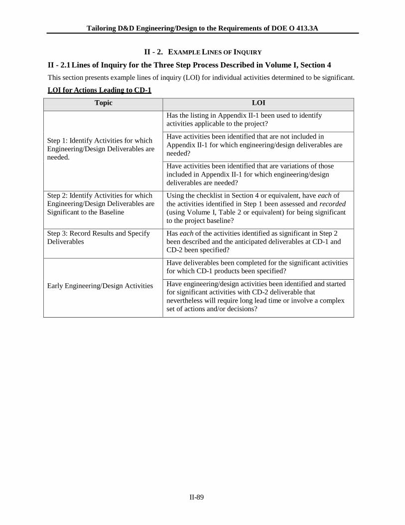
Tailoring D&D Engineering/Design to the Requirements of DOE O 413.3A
II-89
II - 2. EXAMPLE LINES OF INQUIRY
II - 2.1 Lines of Inquiry for the Three Step Process Described in Volume I, Section 4
This section presents example lines of inquiry (LOI) for individual activities determined to be significant.
LOI for Actions Leading to CD-1
Topic LOI
Step 1: Identify Activities for which
Engineering/Design Deliverables are
needed.
Has the listing in Appendix II-1 been used to identify activities applicable to the project?
Have activities been identified that are not included in
Appendix II-1 for which engineering/design deliverables are
needed?
Have activities been identified that are variations of those
included in Appendix II-1 for which engineering/design
deliverables are needed?
Step 2: Identify Activities for which Engineering/Design Deliverables are
Significant to the Baseline
Using the checklist in Section 4 or equivalent, have each of
the activities identified in Step 1 been assessed and recorded
(using Volume I, Table 2 or equivalent) for being significant
to the project baseline?
Step 3: Record Results and Specify Deliverables
Has each of the activities identified as significant in Step 2 been described and the anticipated deliverables at CD-1 and CD-2 been specified?
Early Engineering/Design Activities
Have deliverables been completed for the significant activities for which CD-1 products been specified?
Have engineering/design activities been identified and started for significant activities with CD-2 deliverable that
nevertheless will require long lead time or involve a complex
set of actions and/or decisions?
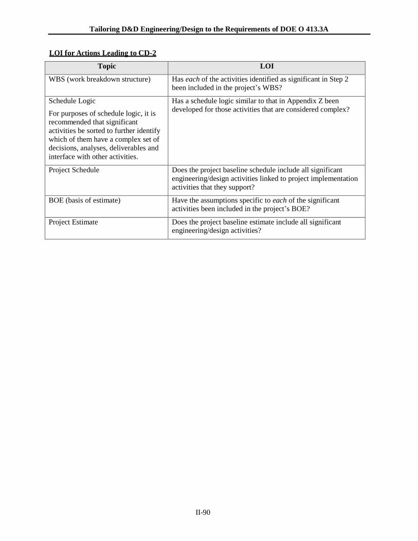
Tailoring D&D Engineering/Design to the Requirements of DOE O 413.3A
II-90
LOI for Actions Leading to CD-2
Topic LOI
WBS (work breakdown structure) Has each of the activities identified as significant in Step 2 been included in the project’s WBS?
Schedule Logic
For purposes of schedule logic, it is
recommended that significant
activities be sorted to further identify
which of them have a complex set of
decisions, analyses, deliverables and
interface with other activities.
Has a schedule logic similar to that in Appendix Z been developed for those activities that are considered complex?
Project Schedule Does the project baseline schedule include all significant
engineering/design activities linked to project implementation
activities that they support?
BOE (basis of estimate) Have the assumptions specific to each of the significant activities been included in the project’s BOE?
Project Estimate Does the project baseline estimate include all significant engineering/design activities?
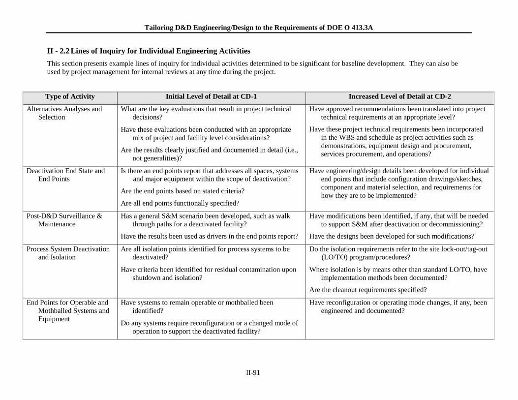
Tailoring D&D Engineering/Design to the Requirements of DOE O 413.3A
II-91
II - 2.2 Lines of Inquiry for Individual Engineering Activities
This section presents example lines of inquiry for individual activities determined to be significant for baseline development. They can also be
used by project management for internal reviews at any time during the project.
Type of Activity Initial Level of Detail at CD-1 Increased Level of Detail at CD-2
Alternatives Analyses and Selection
What are the key evaluations that result in project technical decisions?
Have these evaluations been conducted with an appropriate
mix of project and facility level considerations?
Are the results clearly justified and documented in detail (i.e.,
not generalities)?
Have approved recommendations been translated into project technical requirements at an appropriate level?
Have these project technical requirements been incorporated
in the WBS and schedule as project activities such as
demonstrations, equipment design and procurement,
services procurement, and operations?
Deactivation End State and End Points
Is there an end points report that addresses all spaces, systems and major equipment within the scope of deactivation?
Are the end points based on stated criteria?
Are all end points functionally specified?
Have engineering/design details been developed for individual
end points that include configuration drawings/sketches,
component and material selection, and requirements for
how they are to be implemented?
Post-D&D Surveillance & Maintenance
Has a general S&M scenario been developed, such as walk through paths for a deactivated facility?
Have the results been used as drivers in the end points report?
Have modifications been identified, if any, that will be needed
to support S&M after deactivation or decommissioning?
Have the designs been developed for such modifications?
Process System Deactivation and Isolation
Are all isolation points identified for process systems to be deactivated?
Have criteria been identified for residual contamination upon
shutdown and isolation?
Do the isolation requirements refer to the site lock-out/tag-out (LO/TO) program/procedures?
Where isolation is by means other than standard LO/TO, have
implementation methods been documented?
Are the cleanout requirements specified?
End Points for Operable and
Mothballed Systems and Equipment
Have systems to remain operable or mothballed been
identified?
Do any systems require reconfiguration or a changed mode of
operation to support the deactivated facility?
Have reconfiguration or operating mode changes, if any, been
engineered and documented?
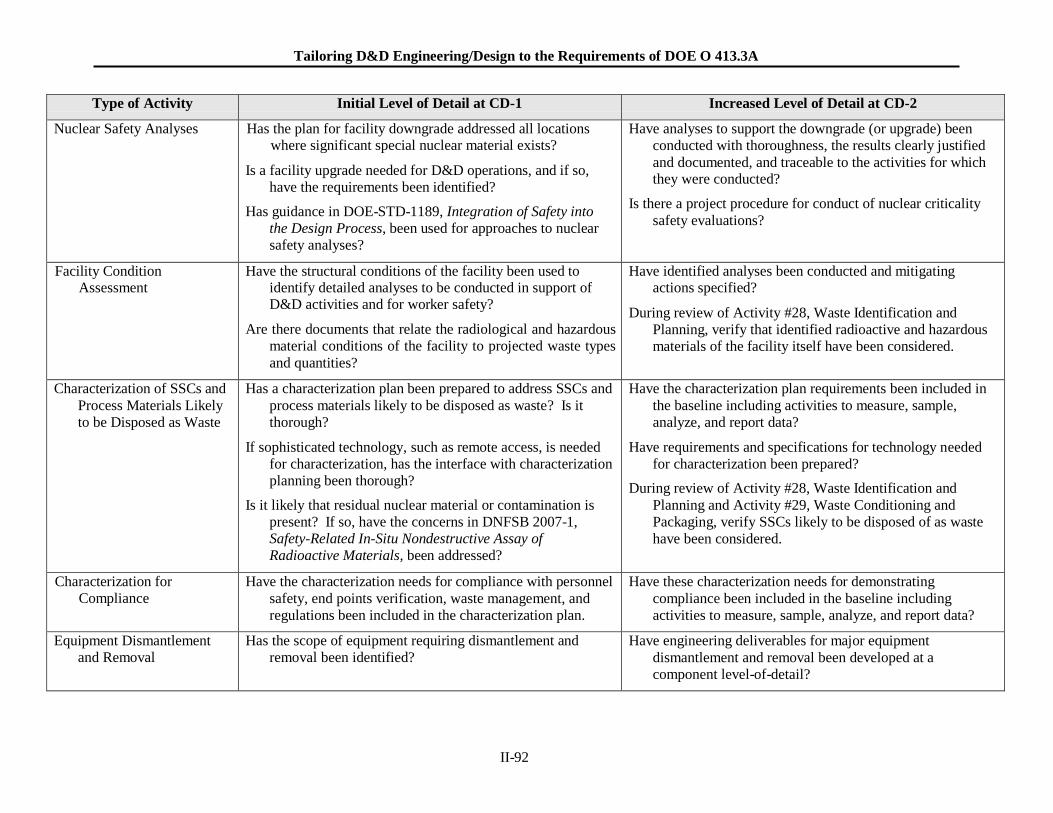
Tailoring D&D Engineering/Design to the Requirements of DOE O 413.3A
II-92
Type of Activity Initial Level of Detail at CD-1 Increased Level of Detail at CD-2
Nuclear Safety Analyses Has the plan for facility downgrade addressed all locations where significant special nuclear material exists?
Is a facility upgrade needed for D&D operations, and if so,
have the requirements been identified?
Has guidance in DOE-STD-1189, Integration of Safety into
the Design Process, been used for approaches to nuclear
safety analyses?
Have analyses to support the downgrade (or upgrade) been
conducted with thoroughness, the results clearly justified
and documented, and traceable to the activities for which they were conducted?
Is there a project procedure for conduct of nuclear criticality
safety evaluations?
Facility Condition Assessment
Have the structural conditions of the facility been used to identify detailed analyses to be conducted in support of D&D activities and for worker safety?
Are there documents that relate the radiological and hazardous
material conditions of the facility to projected waste types
and quantities?
Have identified analyses been conducted and mitigating actions specified?
During review of Activity #28, Waste Identification and
Planning, verify that identified radioactive and hazardous
materials of the facility itself have been considered.
Characterization of SSCs and
Process Materials Likely
to be Disposed as Waste
Has a characterization plan been prepared to address SSCs and
process materials likely to be disposed as waste? Is it
thorough?
If sophisticated technology, such as remote access, is needed
for characterization, has the interface with characterization
planning been thorough?
Is it likely that residual nuclear material or contamination is
present? If so, have the concerns in DNFSB 2007-1,
Safety-Related In-Situ Nondestructive Assay of
Radioactive Materials, been addressed?
Have the characterization plan requirements been included in
the baseline including activities to measure, sample,
analyze, and report data?
Have requirements and specifications for technology needed
for characterization been prepared?
During review of Activity #28, Waste Identification and
Planning and Activity #29, Waste Conditioning and
Packaging, verify SSCs likely to be disposed of as waste
have been considered.
Characterization for
Compliance
Have the characterization needs for compliance with personnel
safety, end points verification, waste management, and
regulations been included in the characterization plan.
Have these characterization needs for demonstrating
compliance been included in the baseline including
activities to measure, sample, analyze, and report data?
Equipment Dismantlement
and Removal
Has the scope of equipment requiring dismantlement and
removal been identified?
Have engineering deliverables for major equipment
dismantlement and removal been developed at a
component level-of-detail?
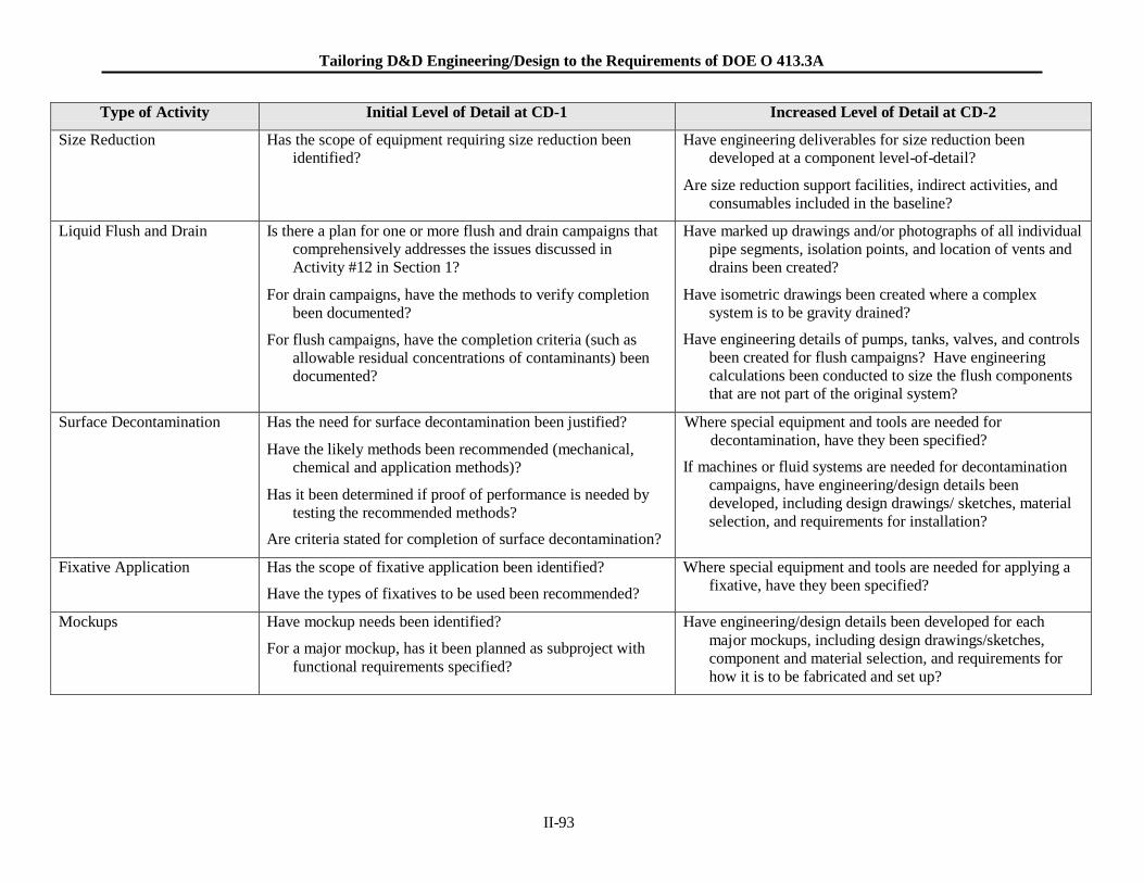
Tailoring D&D Engineering/Design to the Requirements of DOE O 413.3A
II-93
Type of Activity Initial Level of Detail at CD-1 Increased Level of Detail at CD-2
Size Reduction Has the scope of equipment requiring size reduction been identified?
Have engineering deliverables for size reduction been developed at a component level-of-detail?
Are size reduction support facilities, indirect activities, and
consumables included in the baseline?
Liquid Flush and Drain Is there a plan for one or more flush and drain campaigns that comprehensively addresses the issues discussed in
Activity #12 in Section 1?
For drain campaigns, have the methods to verify completion
been documented?
For flush campaigns, have the completion criteria (such as
allowable residual concentrations of contaminants) been
documented?
Have marked up drawings and/or photographs of all individual
pipe segments, isolation points, and location of vents and
drains been created?
Have isometric drawings been created where a complex
system is to be gravity drained?
Have engineering details of pumps, tanks, valves, and controls
been created for flush campaigns? Have engineering
calculations been conducted to size the flush components
that are not part of the original system?
Surface Decontamination Has the need for surface decontamination been justified?
Have the likely methods been recommended (mechanical,
chemical and application methods)?
Has it been determined if proof of performance is needed by
testing the recommended methods?
Are criteria stated for completion of surface decontamination?
Where special equipment and tools are needed for
decontamination, have they been specified?
If machines or fluid systems are needed for decontamination
campaigns, have engineering/design details been
developed, including design drawings/ sketches, material
selection, and requirements for installation?
Fixative Application Has the scope of fixative application been identified?
Have the types of fixatives to be used been recommended?
Where special equipment and tools are needed for applying a
fixative, have they been specified?
Mockups Have mockup needs been identified?
For a major mockup, has it been planned as subproject with
functional requirements specified?
Have engineering/design details been developed for each
major mockups, including design drawings/sketches,
component and material selection, and requirements for
how it is to be fabricated and set up?
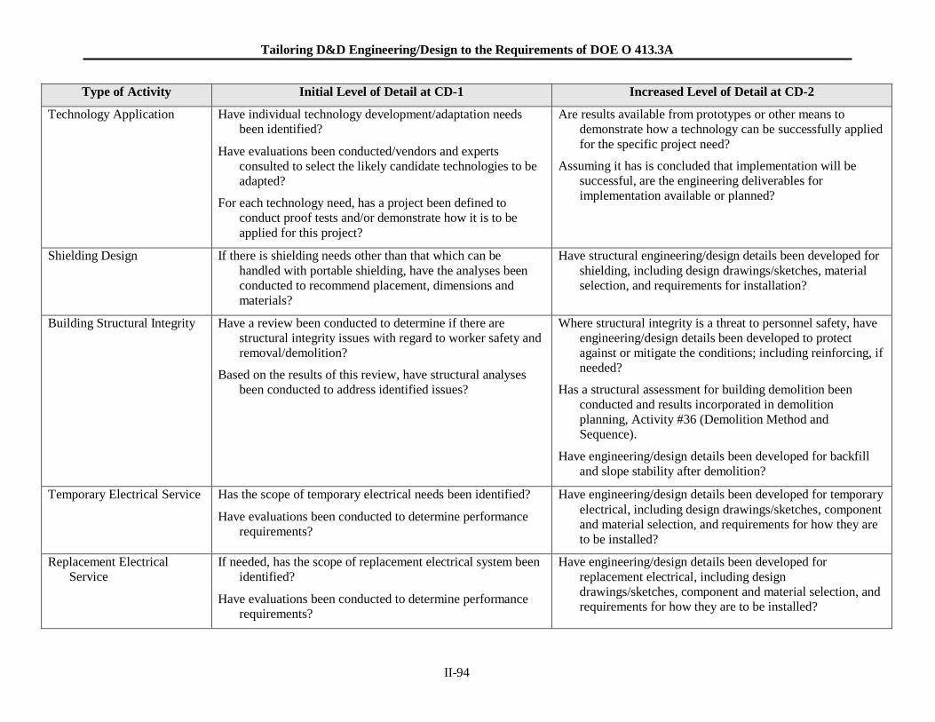
Tailoring D&D Engineering/Design to the Requirements of DOE O 413.3A
II-94
Type of Activity Initial Level of Detail at CD-1 Increased Level of Detail at CD-2
Technology Application Have individual technology development/adaptation needs been identified?
Have evaluations been conducted/vendors and experts
consulted to select the likely candidate technologies to be
adapted?
For each technology need, has a project been defined to
conduct proof tests and/or demonstrate how it is to be
applied for this project?
Are results available from prototypes or other means to
demonstrate how a technology can be successfully applied
for the specific project need?
Assuming it has is concluded that implementation will be
successful, are the engineering deliverables for
implementation available or planned?
Shielding Design If there is shielding needs other than that which can be
handled with portable shielding, have the analyses been
conducted to recommend placement, dimensions and
materials?
Have structural engineering/design details been developed for
shielding, including design drawings/sketches, material
selection, and requirements for installation?
Building Structural Integrity Have a review been conducted to determine if there are
structural integrity issues with regard to worker safety and
removal/demolition?
Based on the results of this review, have structural analyses
been conducted to address identified issues?
Where structural integrity is a threat to personnel safety, have
engineering/design details been developed to protect
against or mitigate the conditions; including reinforcing, if
needed?
Has a structural assessment for building demolition been
conducted and results incorporated in demolition
planning, Activity #36 (Demolition Method and
Sequence).
Have engineering/design details been developed for backfill
and slope stability after demolition?
Temporary Electrical Service Has the scope of temporary electrical needs been identified?
Have evaluations been conducted to determine performance
requirements?
Have engineering/design details been developed for temporary
electrical, including design drawings/sketches, component
and material selection, and requirements for how they are
to be installed?
Replacement Electrical
Service
If needed, has the scope of replacement electrical system been
identified?
Have evaluations been conducted to determine performance
requirements?
Have engineering/design details been developed for
replacement electrical, including design
drawings/sketches, component and material selection, and
requirements for how they are to be installed?
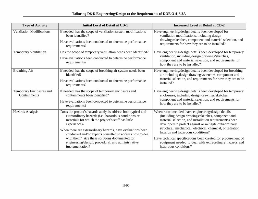
Tailoring D&D Engineering/Design to the Requirements of DOE O 413.3A
II-95
Type of Activity Initial Level of Detail at CD-1 Increased Level of Detail at CD-2
Ventilation Modifications If needed, has the scope of ventilation system modifications been identified?
Have evaluations been conducted to determine performance
requirements?
Have engineering/design details been developed for
ventilation modifications, including design
drawings/sketches, component and material selection, and requirements for how they are to be installed?
Temporary Ventilation Has the scope of temporary ventilation needs been identified?
Have evaluations been conducted to determine performance
requirements?
Have engineering/design details been developed for temporary
ventilation, including design drawings/sketches,
component and material selection, and requirements for
how they are to be installed?
Breathing Air If needed, has the scope of breathing air system needs been identified?
Have evaluations been conducted to determine performance
requirements?
Have engineering/design details been developed for breathing air including design drawings/sketches, component and
material selection, and requirements for how they are to be
installed?
Temporary Enclosures and Containments
If needed, has the scope of temporary enclosures and containments been identified?
Have evaluations been conducted to determine performance
requirements?
Have engineering/design details been developed for temporary
enclosures, including design drawings/sketches,
component and material selection, and requirements for
how they are to be installed?
Hazards Analysis Does the project’s hazards analysis address both typical and
extraordinary hazards (i.e., hazardous conditions or materials for which the project’s staff has little
experience)?
When there are extraordinary hazards, have evaluations been
conducted and/or experts consulted to address how to deal
with them? Are these solutions documented for
engineering/design, procedural, and administrative
implementation?
When recommended, have engineering/design details
(including design drawings/sketches, component and
material selection, and installation requirements) been
developed to protect against or mitigate extraordinary
structural, mechanical, electrical, chemical, or radiation
hazards and hazardous conditions?
Have technical specifications been created for procurement of
equipment needed to deal with extraordinary hazards and
hazardous conditions?
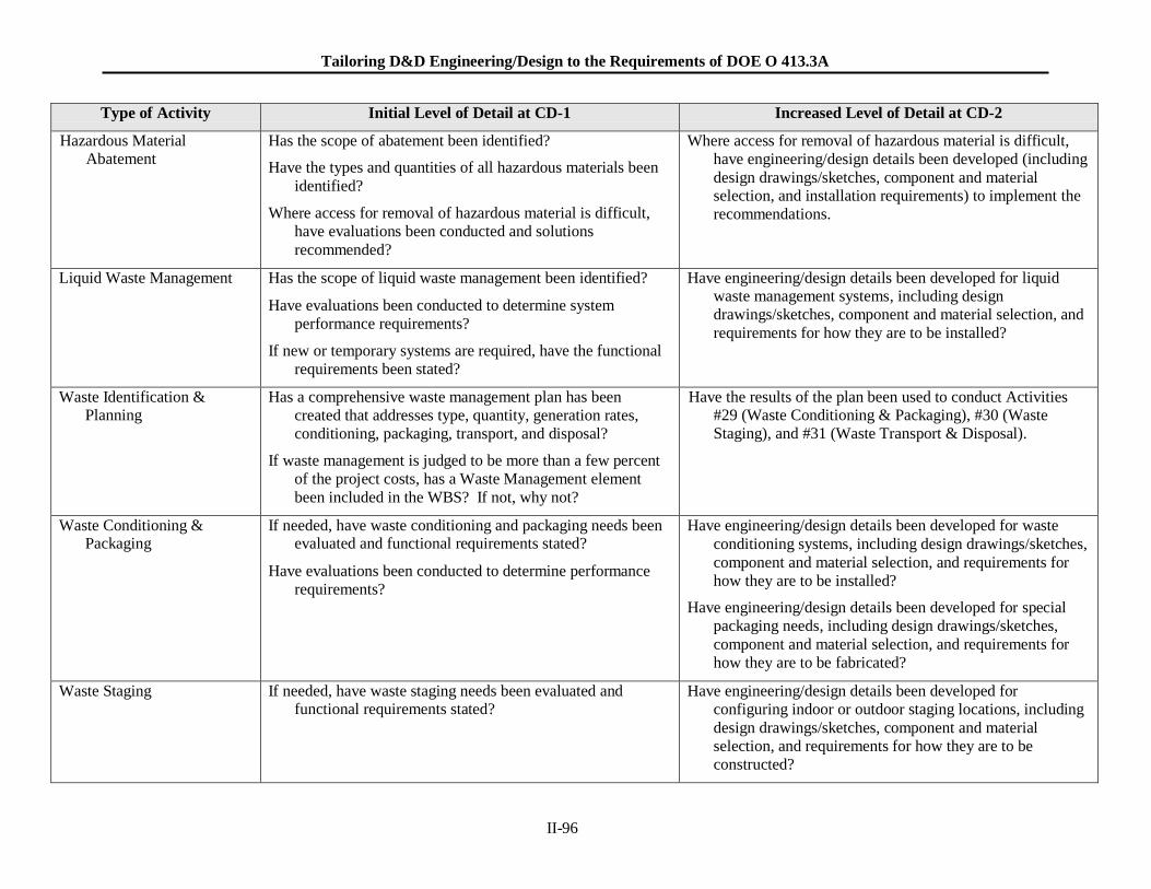
Tailoring D&D Engineering/Design to the Requirements of DOE O 413.3A
II-96
Type of Activity Initial Level of Detail at CD-1 Increased Level of Detail at CD-2
Hazardous Material Abatement
Has the scope of abatement been identified?
Have the types and quantities of all hazardous materials been
identified?
Where access for removal of hazardous material is difficult,
have evaluations been conducted and solutions
recommended?
Where access for removal of hazardous material is difficult,
have engineering/design details been developed (including
design drawings/sketches, component and material selection, and installation requirements) to implement the
recommendations.
Liquid Waste Management Has the scope of liquid waste management been identified?
Have evaluations been conducted to determine system
performance requirements?
If new or temporary systems are required, have the functional
requirements been stated?
Have engineering/design details been developed for liquid waste management systems, including design
drawings/sketches, component and material selection, and
requirements for how they are to be installed?
Waste Identification & Planning
Has a comprehensive waste management plan has been
created that addresses type, quantity, generation rates,
conditioning, packaging, transport, and disposal?
If waste management is judged to be more than a few percent
of the project costs, has a Waste Management element
been included in the WBS? If not, why not?
Have the results of the plan been used to conduct Activities #29 (Waste Conditioning & Packaging), #30 (Waste
Staging), and #31 (Waste Transport & Disposal).
Waste Conditioning & Packaging
If needed, have waste conditioning and packaging needs been evaluated and functional requirements stated?
Have evaluations been conducted to determine performance
requirements?
Have engineering/design details been developed for waste
conditioning systems, including design drawings/sketches,
component and material selection, and requirements for
how they are to be installed?
Have engineering/design details been developed for special
packaging needs, including design drawings/sketches,
component and material selection, and requirements for
how they are to be fabricated?
Waste Staging If needed, have waste staging needs been evaluated and functional requirements stated?
Have engineering/design details been developed for
configuring indoor or outdoor staging locations, including
design drawings/sketches, component and material
selection, and requirements for how they are to be
constructed?
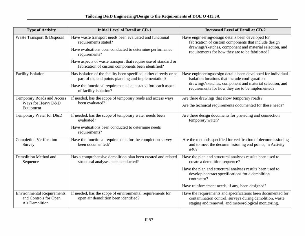
Tailoring D&D Engineering/Design to the Requirements of DOE O 413.3A
II-97
Type of Activity Initial Level of Detail at CD-1 Increased Level of Detail at CD-2
Waste Transport & Disposal Have waste transport needs been evaluated and functional requirements stated?
Have evaluations been conducted to determine performance
requirements?
Have aspects of waste transport that require use of standard or
fabrication of custom components been identified?
Have engineering/design details been developed for
fabrication of custom components that include design
drawings/sketches, component and material selection, and requirements for how they are to be fabricated?
Facility Isolation Has isolation of the facility been specified, either directly or as part of the end points planning and implementation?
Have the functional requirements been stated fore each aspect
of facility isolation?
Have engineering/design details been developed for individual isolation locations that include configuration
drawings/sketches, component and material selection, and
requirements for how they are to be implemented?
Temporary Roads and Access
Ways for Heavy D&D
Equipment
If needed, has the scope of temporary roads and access ways been evaluated?
Are there drawings that show temporary roads?
Are the technical requirements documented for these needs?
Temporary Water for D&D If needed, has the scope of temporary water needs been evaluated?
Have evaluations been conducted to determine needs
requirements?
Are there design documents for providing and connection temporary water?
Completion Verification Survey
Have the functional requirements for the completion survey been documented?
Are the methods specified for verification of decommissioning and to meet the decommissioning end points, in Activity
#40?
Demolition Method and Sequence
Has a comprehensive demolition plan been created and related structural analyses been conducted?
Have the plan and structural analyses results been used to create a demolition sequence?
Have the plan and structural analyses results been used to
develop contract specifications for a demolition
contractor?
Have reinforcement needs, if any, been designed?
Environmental Requirements and Controls for Open
Air Demolition
If needed, has the scope of environmental requirements for open air demolition been identified?
Have the requirements and specifications been documented for
contamination control, surveys during demolition, waste
staging and removal, and meteorological monitoring,
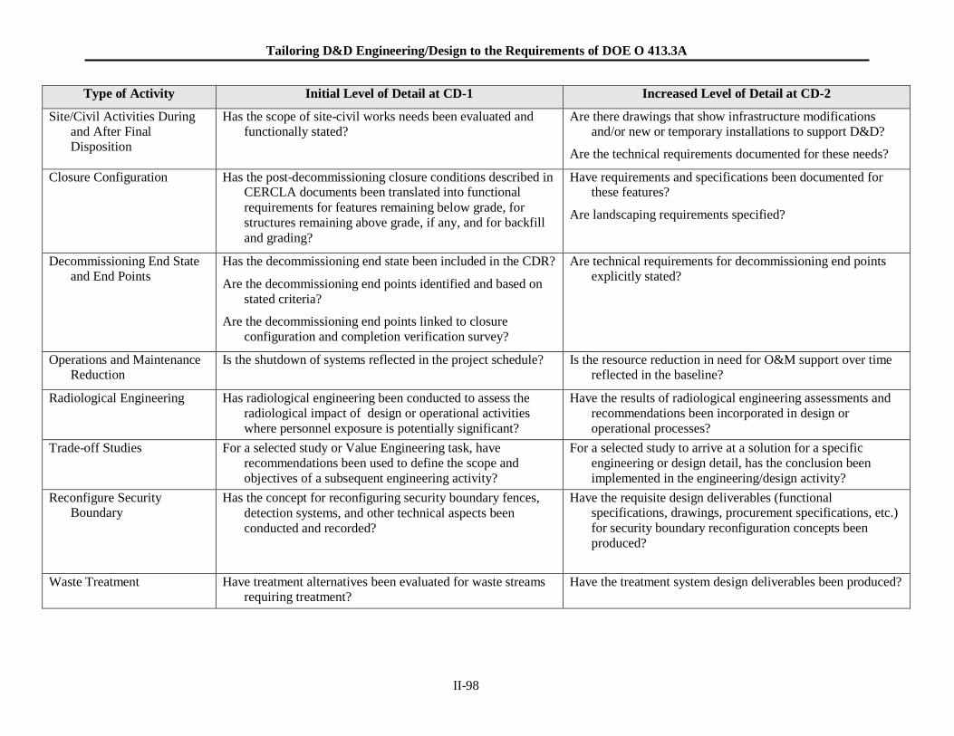
Tailoring D&D Engineering/Design to the Requirements of DOE O 413.3A
II-98
Type of Activity Initial Level of Detail at CD-1 Increased Level of Detail at CD-2
Site/Civil Activities During and After Final Disposition
Has the scope of site-civil works needs been evaluated and functionally stated?
Are there drawings that show infrastructure modifications and/or new or temporary installations to support D&D?
Are the technical requirements documented for these needs?
Closure Configuration Has the post-decommissioning closure conditions described in CERCLA documents been translated into functional
requirements for features remaining below grade, for
structures remaining above grade, if any, and for backfill
and grading?
Have requirements and specifications been documented for these features?
Are landscaping requirements specified?
Decommissioning End State and End Points
Has the decommissioning end state been included in the CDR?
Are the decommissioning end points identified and based on
stated criteria?
Are the decommissioning end points linked to closure
configuration and completion verification survey?
Are technical requirements for decommissioning end points explicitly stated?
Operations and Maintenance Reduction
Is the shutdown of systems reflected in the project schedule? Is the resource reduction in need for O&M support over time reflected in the baseline?
Radiological Engineering Has radiological engineering been conducted to assess the
radiological impact of design or operational activities
where personnel exposure is potentially significant?
Have the results of radiological engineering assessments and
recommendations been incorporated in design or
operational processes?
Trade-off Studies For a selected study or Value Engineering task, have
recommendations been used to define the scope and
objectives of a subsequent engineering activity?
For a selected study to arrive at a solution for a specific
engineering or design detail, has the conclusion been
implemented in the engineering/design activity?
Reconfigure Security Boundary
Has the concept for reconfiguring security boundary fences,
detection systems, and other technical aspects been
conducted and recorded?
Have the requisite design deliverables (functional specifications, drawings, procurement specifications, etc.)
for security boundary reconfiguration concepts been
produced?
Waste Treatment Have treatment alternatives been evaluated for waste streams requiring treatment?
Have the treatment system design deliverables been produced?
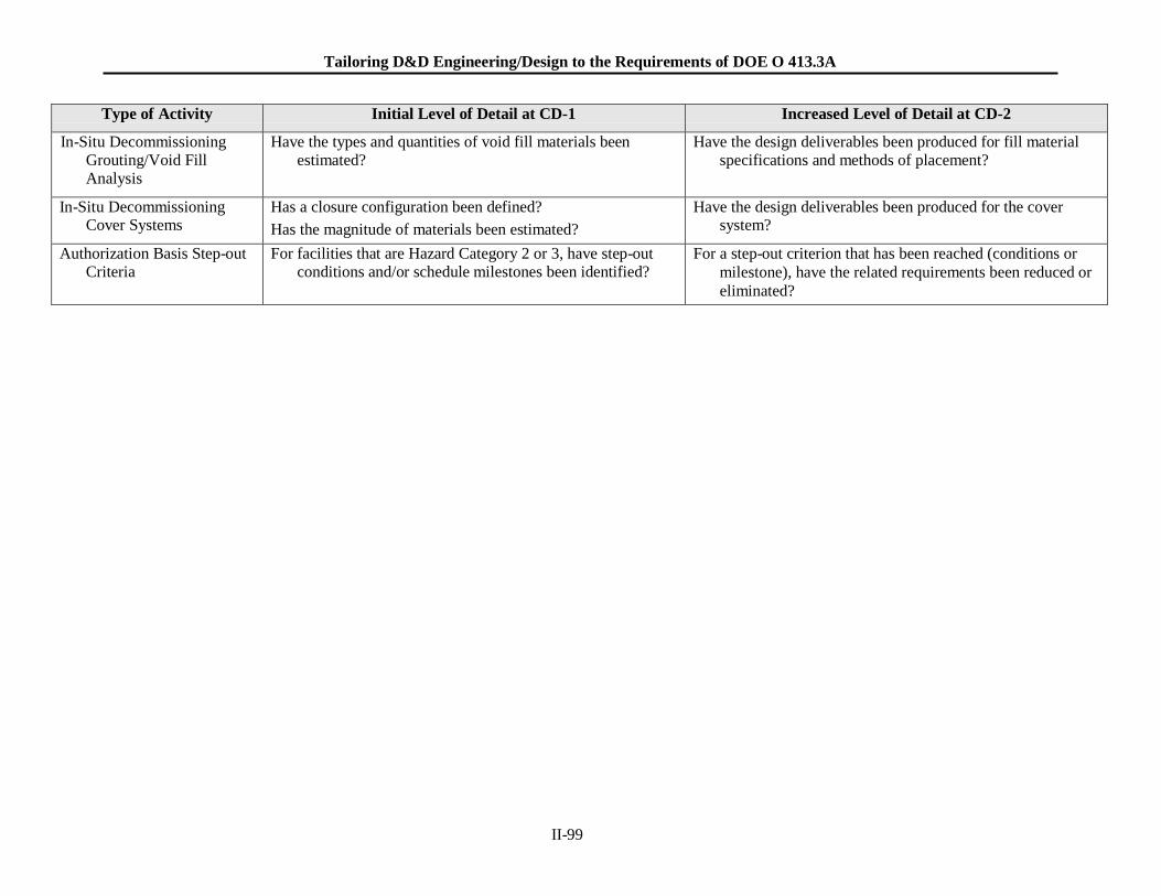
Tailoring D&D Engineering/Design to the Requirements of DOE O 413.3A
II-99
Type of Activity Initial Level of Detail at CD-1 Increased Level of Detail at CD-2
In-Situ Decommissioning Grouting/Void Fill Analysis
Have the types and quantities of void fill materials been estimated?
Have the design deliverables been produced for fill material specifications and methods of placement?
In-Situ Decommissioning Cover Systems
Has a closure configuration been defined?
Has the magnitude of materials been estimated?
Have the design deliverables been produced for the cover system?
Authorization Basis Step-out Criteria
For facilities that are Hazard Category 2 or 3, have step-out conditions and/or schedule milestones been identified?
For a step-out criterion that has been reached (conditions or
milestone), have the related requirements been reduced or
eliminated?
Tailoring D&D Engineering/Design to the Requirements of DOE O 413.3A
II-100
II - 3. EXAMPLE PROJECT
II - 3.1 Example Project Description
To provide an example for applying the method in Section 4, a fictitious project is presented for
deactivating and demolishing a relatively small experimental reactor facility. In this example, the
project’s three phases include:
Deactivation Phase: the facility described below is to be prepared for a two-year period of post-
deactivation period of low cost S&M consistent with maintaining the facility in a safe condition.
Post-deactivation S&M phase: the S&M mode will have a skeleton crew that work on day shift
for 5 days-a-week. Electrical power is to be maintained and systems required for safety will
remain operable.
Demolition Phase: All facilities and systems, above and below grade are to be removed and the
site is to be cleaned up to free-release standards.
The overall strategy is that deactivation, post-deactivation S&M, and demolition will be planned in detail
as one project. That is, the project baseline is to include all three phases.
The method presented in Sections 4 and Volume II, Section 1 of this guide is used to identify
engineering/design deliverables needed for the baseline as well as illustrating the increasing level of detail
for deliverables at CD-1, CD-2, and CD-3.
II - 3.2 Example Facility Description
The overall function of the facility was the preparation, irradiation, and post-irradiation examination of
specimens in a small research reactor. It is geographically located where wintertime sub-zero
temperatures are experienced. The site is in the eastern half of the USA and considered a “wet” site; that
is, moderately rainy summers, and snow accumulation in the winter. There is no on-site waste disposal
facility.
All fuel and nuclear materials have been removed; facility hazard classification is Radiological. In
addition, comprehensive characterization information and data are available.
Tables 2, 3, and 4 describe the physical facility and conditions for spaces and systems.
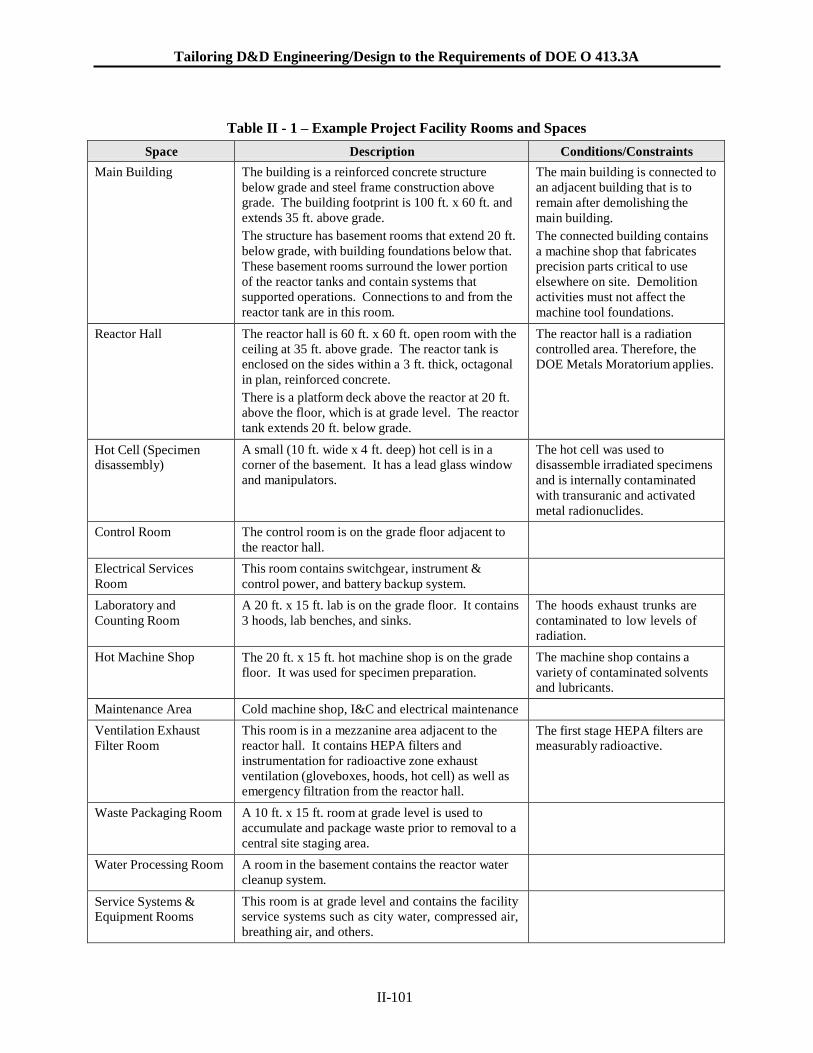
Tailoring D&D Engineering/Design to the Requirements of DOE O 413.3A
II-101
Table II - 1 – Example Project Facility Rooms and Spaces
Space Description Conditions/Constraints
Main Building The building is a reinforced concrete structure
below grade and steel frame construction above
grade. The building footprint is 100 ft. x 60 ft. and
extends 35 ft. above grade.
The structure has basement rooms that extend 20 ft.
below grade, with building foundations below that.
These basement rooms surround the lower portion
of the reactor tanks and contain systems that
supported operations. Connections to and from the
reactor tank are in this room.
The main building is connected to
an adjacent building that is to
remain after demolishing the
main building.
The connected building contains
a machine shop that fabricates
precision parts critical to use
elsewhere on site. Demolition
activities must not affect the
machine tool foundations.
Reactor Hall The reactor hall is 60 ft. x 60 ft. open room with the
ceiling at 35 ft. above grade. The reactor tank is
enclosed on the sides within a 3 ft. thick, octagonal
in plan, reinforced concrete.
There is a platform deck above the reactor at 20 ft.
above the floor, which is at grade level. The reactor
tank extends 20 ft. below grade.
The reactor hall is a radiation
controlled area. Therefore, the
DOE Metals Moratorium applies.
Hot Cell (Specimen disassembly)
A small (10 ft. wide x 4 ft. deep) hot cell is in a
corner of the basement. It has a lead glass window
and manipulators.
The hot cell was used to
disassemble irradiated specimens
and is internally contaminated
with transuranic and activated
metal radionuclides.
Control Room The control room is on the grade floor adjacent to
the reactor hall.
Electrical Services
Room
This room contains switchgear, instrument &
control power, and battery backup system.
Laboratory and
Counting Room
A 20 ft. x 15 ft. lab is on the grade floor. It contains
3 hoods, lab benches, and sinks.
The hoods exhaust trunks are
contaminated to low levels of
radiation.
Hot Machine Shop The 20 ft. x 15 ft. hot machine shop is on the grade
floor. It was used for specimen preparation.
The machine shop contains a
variety of contaminated solvents
and lubricants.
Maintenance Area Cold machine shop, I&C and electrical maintenance
Ventilation Exhaust
Filter Room
This room is in a mezzanine area adjacent to the
reactor hall. It contains HEPA filters and
instrumentation for radioactive zone exhaust
ventilation (gloveboxes, hoods, hot cell) as well as
emergency filtration from the reactor hall.
The first stage HEPA filters are measurably radioactive.
Waste Packaging Room A 10 ft. x 15 ft. room at grade level is used to
accumulate and package waste prior to removal to a
central site staging area.
Water Processing Room A room in the basement contains the reactor water
cleanup system.
Service Systems & Equipment Rooms
This room is at grade level and contains the facility
service systems such as city water, compressed air,
breathing air, and others.
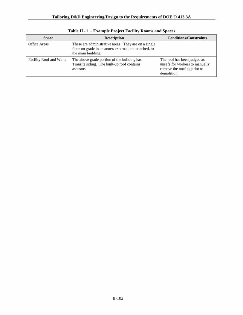
Tailoring D&D Engineering/Design to the Requirements of DOE O 413.3A
II-102
Table II - 1 – Example Project Facility Rooms and Spaces
Space Description Conditions/Constraints
Office Areas These are administrative areas. They are on a single
floor on grade in an annex external, but attached, to
the main building.
Facility Roof and Walls The above grade portion of the building has
Transite siding. The built-up roof contains
asbestos.
The roof has been judged as
unsafe for workers to manually
remove the roofing prior to
demolition.
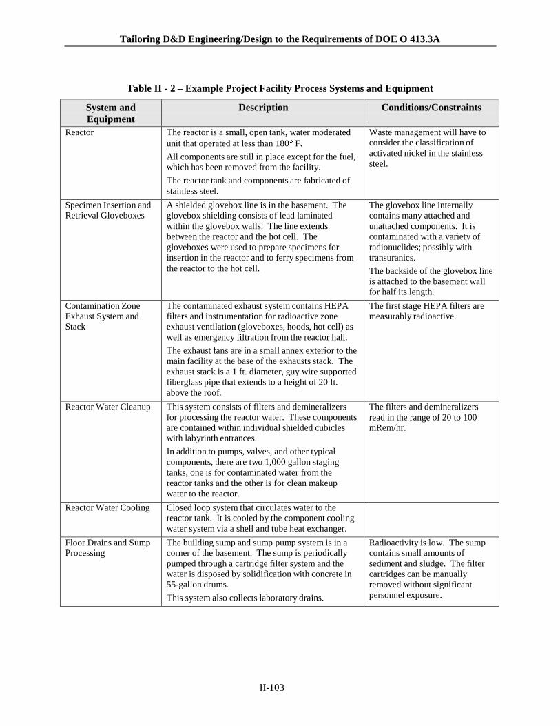
Tailoring D&D Engineering/Design to the Requirements of DOE O 413.3A
II-103
Table II - 2 – Example Project Facility Process Systems and Equipment
System and
Equipment
Description Conditions/Constraints
Reactor The reactor is a small, open tank, water moderated
unit that operated at less than 180 F.
All components are still in place except for the fuel,
which has been removed from the facility.
The reactor tank and components are fabricated of
stainless steel.
Waste management will have to consider the classification of
activated nickel in the stainless
steel.
Specimen Insertion and Retrieval Gloveboxes
A shielded glovebox line is in the basement. The
glovebox shielding consists of lead laminated
within the glovebox walls. The line extends
between the reactor and the hot cell. The
gloveboxes were used to prepare specimens for
insertion in the reactor and to ferry specimens from
the reactor to the hot cell.
The glovebox line internally
contains many attached and
unattached components. It is
contaminated with a variety of
radionuclides; possibly with
transuranics.
The backside of the glovebox line
is attached to the basement wall
for half its length.
Contamination Zone Exhaust System and
Stack
The contaminated exhaust system contains HEPA filters and instrumentation for radioactive zone
exhaust ventilation (gloveboxes, hoods, hot cell) as
well as emergency filtration from the reactor hall.
The exhaust fans are in a small annex exterior to the
main facility at the base of the exhausts stack. The
exhaust stack is a 1 ft. diameter, guy wire supported
fiberglass pipe that extends to a height of 20 ft.
above the roof.
The first stage HEPA filters are measurably radioactive.
Reactor Water Cleanup This system consists of filters and demineralizers for processing the reactor water. These components
are contained within individual shielded cubicles
with labyrinth entrances.
In addition to pumps, valves, and other typical
components, there are two 1,000 gallon staging
tanks, one is for contaminated water from the
reactor tanks and the other is for clean makeup
water to the reactor.
The filters and demineralizers
read in the range of 20 to 100 mRem/hr.
Reactor Water Cooling Closed loop system that circulates water to the reactor tank. It is cooled by the component cooling
water system via a shell and tube heat exchanger.
Floor Drains and Sump Processing
The building sump and sump pump system is in a corner of the basement. The sump is periodically
pumped through a cartridge filter system and the
water is disposed by solidification with concrete in
55-gallon drums.
This system also collects laboratory drains.
Radioactivity is low. The sump contains small amounts of
sediment and sludge. The filter
cartridges can be manually
removed without significant
personnel exposure.
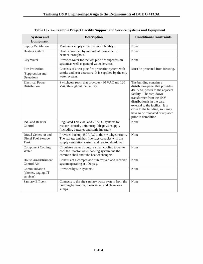
Tailoring D&D Engineering/Design to the Requirements of DOE O 413.3A
II-104
Table II - 3 – Example Project Facility Support and Service Systems and Equipment
System and
Equipment
Description Conditions/Constraints
Supply Ventilation Maintains supply air to the entire facility. None
Heating system Heat is provided by individual room electric heaters throughout.
None
City Water Provides water for the wet pipe fire suppression system as well as general water services.
None
Fire Protection
(Suppression and
Detection)
Consists of a wet pipe fire protection system with
smoke and heat detectors. It is supplied by the city water system.
Must be protected from freezing.
Electrical Power Distribution
Switchgear room that provides 480 VAC and 120 VAC throughout the facility.
The building contains a distribution panel that provides
480 VAC power to the adjacent
facility. The step-down
transformer from the 4KV
distribution is in the yard
external to the facility. It is
close to the building, so it may
have to be relocated or replaced
prior to demolition
I&C and Reactor Control
Regulated 120 VAC and 28 VDC systems for reactor controls, uninterruptible power supply
(including batteries and static inverter)
None
Diesel Generator and Diesel Fuel Storage
Tank
Provides backup 480 VAC to the switchgear room. The storage tank has five days capacity with the
supply ventilation system and reactor shutdown.
None
Component Cooling Water
Circulates water through a small cooling tower to cool the reactor water cooling system via the
common shell and tube heat exchangers
None
House Air/Instrument Control Air
Consists of a compressor, filter/dryer, and receiver system operating at 100 psig.
None
Communication (phones, paging, IT
services)
Provided by site systems. None
Sanitary Effluent Connects to the site sanitary waste system from the building bathrooms, clean sinks, and clean area
sumps.
None
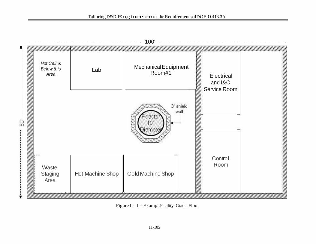
Tailoring D&D Enginee en to tlte Requirements ofDOE 0 413.3A
11-105
•
-----------------------------------------------· 100' - ----------------------------------------------------·
Hot Cell is Below this
Area
Lab Mechanical Equipment
Room#1 Electrical
and I&C
Service Room
Waste Staging
Area
Hot Machine Shop Cold Machine Shop
Figure II- I -Examp., Facility Grade Floor
Control Room
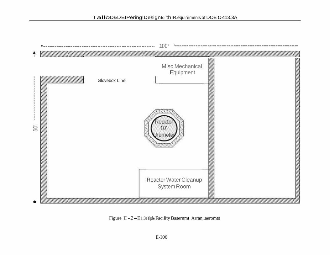
TalloD&DEIPering!Design to th!R.equiremenls of DOE 0 413.3A
II-I 06
•-----------------------------------------------· 1oo· ·------ ---- ---- -------- ------------------------------
Glovebox Line
Misc.Mechanical Equipment
Reactor Water Cleanup
System Room
•
Figure II - 2 -E11311lple Facility Basernmt Arran,.aeromts
Tailoring D&D Engineering/Design to the Requirements of DOE O 413.3A
II-107
II - 3.3 Example Project Significant Engineering/Design Activities
The example project CD-0 decisions and technical strategy that has evolved while developing the overall
conceptual design provide the bases for selecting those project activities judged to be significant; that is,
significant with regard to the need for detailed engineering/design deliverables to support the baseline.
The overall strategy is that deactivation, post-deactivation S&M, and demolition will be planned in detail
as one project. For deactivation, key aspects of this strategy include the following considerations:
The facility will not be deactivated to a “cold and dark” condition because water will remain in
the reactor tank and in the fire protection system during the cold winter. The primary objective of
deactivation is to reduce staff needs and to isolate systems no longer needed.
The ventilation system will be modified to exhaust only; the Supply Ventilation will be shut
down. This decision reduces further the chances of an inadvertent release of contamination to the
environment, especially in light of the facility not being continuously occupied.
Electrical power to the adjacent facility will be re-routed during deactivation and the external
transformer will be relocated or replaced. Electrical power to the reactor facility will be maintained during and following deactivation until a time prior to demolition when all operable
systems can be shutdown.
The fire protection system, which is a wet pipe system, will remain operable until just prior to
decommissioning.
For decommissioning, the following are key considerations:
The major challenge is disassembly and removal of the reactor structural elements and internals,
which are underwater.
Size reduction and packaging the resulting waste will be conducted within the facility.
A decision is needed whether to process the large amount of water in the reactor tank with the
installed system or with vendor supplied skid mounted systems.
Entry to the hot cell will be required to clean out loose items and to prepare it for demolition.
Access within the gloveboxes will be needed to clean out loose items and for preparation for
removal.
Because of the sensitivity of the connected building that will remain operational, a very detailed
analysis is required of the best way to separate the two before demolition.
The DOE metals moratorium will have a significant impact on the ability to dispose of structural
steel that might otherwise be considered non-radioactive.
In the interest of worker safety, permission will be sought to not abate the roof materials prior to
demolition. This will require technical justification.
The facility will be removed to a “green field” end state.
Open air demolition will be the baseline approach for final building removal. The building will
have to be decontaminated and surveyed, as needed, to free-release it prior to demolition.
With these strategic decisions Table II - 4 summarizes the bases for deciding which activities required
detailed engineering/design deliverables to support the baseline. Table II - 4 emulates Table 2 in Volume
I, Section 4. The first forty-one activities in Table II - 4 are the same as in Section 1. Activity #42, “Hot
Cell Preparation for Demolition,” has been added for this project.

Tailoring D&D Engineering/Design to the Requirements of DOE O 413.3A
II-108
II - 3.4 Example Project Lessons Learned
In creating this example, the authors ended up reconsidering those activities judged to be significant with
regard to detailed engineering/design deliverables for baseline development. As discussed in the body of
this guide, the criterion for not being significant is when the baseline can rely upon the skill and judgment
of the project’s engineers, estimators, schedulers and not require such detail. This criterion was revisited
several times, eventually reducing the significant activities in this example from fifteen to ten based on
the following:
Activities #9, “Characterization for Compliance” and #17, “Shielding Design” significance was
determined to be specific to and integral with other activities; thus not requiring a designation as
significant.
Activity #12, “Liquid Flush and Drain” was initially perceived to be complex until it was
understood that the liquid system is small and although the reactor tank is large, the water is not
expected to be very contaminated, if at all.
Activity #29, “Waste Conditioning & Packaging” was initially perceived to be complex until it was understood that the vast bulk of material to be packaged is size-reduced metal and solid
waste from radiological controls; for which conditioning and packaging are straightforward.
Activities #4, “Process System Deactivation and Isolation” and #5, “End Points for Operable and
Mothballed Systems and Equipment” were initially included because they are needed early in the
project schedule; however, the details are not needed for a reliable baseline. This does not mean
that such engineering development is not needed early for reasons other than the baseline.
In addition, it became clear that:
Activity #11, “Size Reduction” needed to be addressed in two separate activity sheets because
size reduction of gloveboxes is considerably different from the reactor tank.
Activity #42, “Hot Cell Preparation for Demolition” was added because there was no comparable
activity in Section 1.
Overall, this exercise of creating a fictitious facility with typical D&D challenge and then evaluating the
significant activities for baseline development demonstrated that the process in Section 4 can be a useful
planning tool.
A final word of caution is appropriate. This fictitious example is based on a limited mixture of challenges
from past projects. It should not be considered anywhere near complete in comparison with a similar
project in the field.
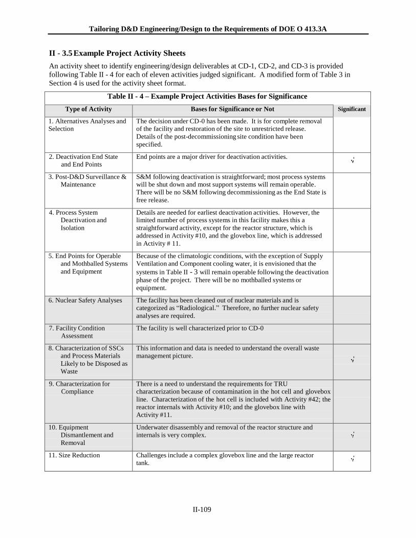
Tailoring D&D Engineering/Design to the Requirements of DOE O 413.3A
II-109
II - 3.5 Example Project Activity Sheets
An activity sheet to identify engineering/design deliverables at CD-1, CD-2, and CD-3 is provided
following Table II - 4 for each of eleven activities judged significant. A modified form of Table 3 in
Section 4 is used for the activity sheet format.
Table II - 4 – Example Project Activities Bases for Significance
Type of Activity Bases for Significance or Not Significant
1. Alternatives Analyses and Selection
The decision under CD-0 has been made. It is for complete removal of the facility and restoration of the site to unrestricted release.
Details of the post-decommissioning site condition have been
specified.
2. Deactivation End State and End Points
End points are a major driver for deactivation activities.
3. Post-D&D Surveillance & Maintenance
S&M following deactivation is straightforward; most process systems will be shut down and most support systems will remain operable.
There will be no S&M following decommissioning as the End State is
free release.
4. Process System Deactivation and
Isolation
Details are needed for earliest deactivation activities. However, the limited number of process systems in this facility makes this a
straightforward activity, except for the reactor structure, which is
addressed in Activity #10, and the glovebox line, which is addressed
in Activity # 11.
5. End Points for Operable and Mothballed Systems
and Equipment
Because of the climatologic conditions, with the exception of Supply Ventilation and Component cooling water, it is envisioned that the
systems in Table II - 3 will remain operable following the deactivation
phase of the project. There will be no mothballed systems or
equipment.
6. Nuclear Safety Analyses The facility has been cleaned out of nuclear materials and is categorized as “Radiological.” Therefore, no further nuclear safety
analyses are required.
7. Facility Condition Assessment
The facility is well characterized prior to CD-0
8. Characterization of SSCs and Process Materials
Likely to be Disposed as
Waste
This information and data is needed to understand the overall waste management picture.
9. Characterization for Compliance
There is a need to understand the requirements for TRU characterization because of contamination in the hot cell and glovebox
line. Characterization of the hot cell is included with Activity #42; the
reactor internals with Activity #10; and the glovebox line with
Activity #11.
10. Equipment Dismantlement and
Removal
Underwater disassembly and removal of the reactor structure and internals is very complex.
11. Size Reduction Challenges include a complex glovebox line and the large reactor tank.
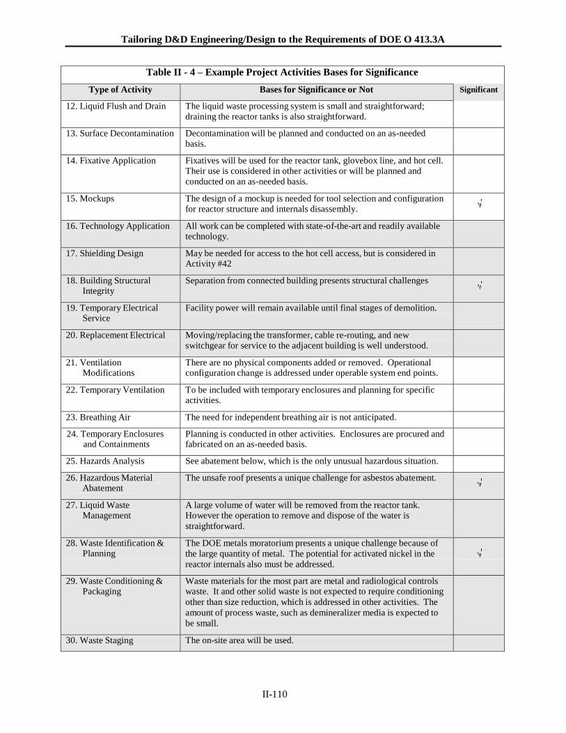
Tailoring D&D Engineering/Design to the Requirements of DOE O 413.3A
II-110
Table II - 4 – Example Project Activities Bases for Significance
Type of Activity Bases for Significance or Not Significant
12. Liquid Flush and Drain The liquid waste processing system is small and straightforward; draining the reactor tanks is also straightforward.
13. Surface Decontamination Decontamination will be planned and conducted on an as-needed basis.
14. Fixative Application Fixatives will be used for the reactor tank, glovebox line, and hot cell. Their use is considered in other activities or will be planned and
conducted on an as-needed basis.
15. Mockups The design of a mockup is needed for tool selection and configuration for reactor structure and internals disassembly.
16. Technology Application All work can be completed with state-of-the-art and readily available technology.
17. Shielding Design May be needed for access to the hot cell access, but is considered in Activity #42
18. Building Structural Integrity
Separation from connected building presents structural challenges
19. Temporary Electrical Service
Facility power will remain available until final stages of demolition.
20. Replacement Electrical Moving/replacing the transformer, cable re-routing, and new switchgear for service to the adjacent building is well understood.
21. Ventilation Modifications
There are no physical components added or removed. Operational configuration change is addressed under operable system end points.
22. Temporary Ventilation To be included with temporary enclosures and planning for specific activities.
23. Breathing Air The need for independent breathing air is not anticipated.
24. Temporary Enclosures and Containments
Planning is conducted in other activities. Enclosures are procured and fabricated on an as-needed basis.
25. Hazards Analysis See abatement below, which is the only unusual hazardous situation.
26. Hazardous Material Abatement
The unsafe roof presents a unique challenge for asbestos abatement.
27. Liquid Waste Management
A large volume of water will be removed from the reactor tank. However the operation to remove and dispose of the water is
straightforward.
28. Waste Identification & Planning
The DOE metals moratorium presents a unique challenge because of
the large quantity of metal. The potential for activated nickel in the
reactor internals also must be addressed.
29. Waste Conditioning & Packaging
Waste materials for the most part are metal and radiological controls waste. It and other solid waste is not expected to require conditioning
other than size reduction, which is addressed in other activities. The
amount of process waste, such as demineralizer media is expected to
be small.
30. Waste Staging The on-site area will be used.
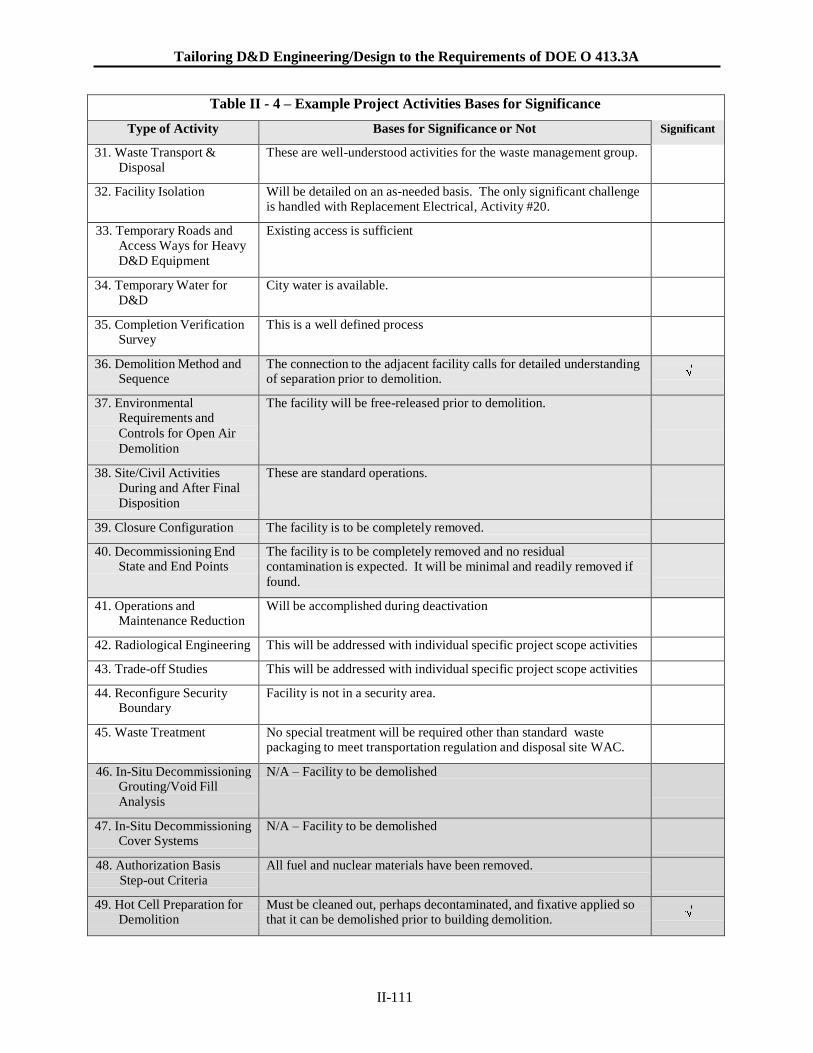
Tailoring D&D Engineering/Design to the Requirements of DOE O 413.3A
II-111
Table II - 4 – Example Project Activities Bases for Significance
Type of Activity Bases for Significance or Not Significant
31. Waste Transport & Disposal
These are well-understood activities for the waste management group.
32. Facility Isolation Will be detailed on an as-needed basis. The only significant challenge is handled with Replacement Electrical, Activity #20.
33. Temporary Roads and Access Ways for Heavy
D&D Equipment
Existing access is sufficient
34. Temporary Water for D&D
City water is available.
35. Completion Verification Survey
This is a well defined process
36. Demolition Method and Sequence
The connection to the adjacent facility calls for detailed understanding of separation prior to demolition.
37. Environmental Requirements and
Controls for Open Air
Demolition
The facility will be free-released prior to demolition.
38. Site/Civil Activities During and After Final
Disposition
These are standard operations.
39. Closure Configuration The facility is to be completely removed.
40. Decommissioning End State and End Points
The facility is to be completely removed and no residual contamination is expected. It will be minimal and readily removed if
found.
41. Operations and Maintenance Reduction
Will be accomplished during deactivation
42. Radiological Engineering This will be addressed with individual specific project scope activities
43. Trade-off Studies This will be addressed with individual specific project scope activities
44. Reconfigure Security Boundary
Facility is not in a security area.
45. Waste Treatment No special treatment will be required other than standard waste packaging to meet transportation regulation and disposal site WAC.
46. In-Situ Decommissioning Grouting/Void Fill
Analysis
N/A – Facility to be demolished
47. In-Situ Decommissioning Cover Systems
N/A – Facility to be demolished
48. Authorization Basis Step-out Criteria
All fuel and nuclear materials have been removed.
49. Hot Cell Preparation for Demolition
Must be cleaned out, perhaps decontaminated, and fixative applied so that it can be demolished prior to building demolition.
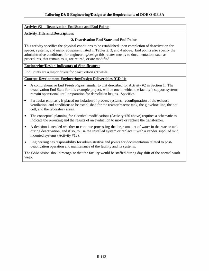
Tailoring D&D Engineering/Design to the Requirements of DOE O 413.3A
II-112
Activity #2 – Deactivation End State and End Points
Activity Title and Description:
2. Deactivation End State and End Points
This activity specifies the physical conditions to be established upon completion of deactivation for
spaces, systems, and major equipment listed in Tables 2, 3, and 4 above. End points also specify the
administrative conditions; for engineering/design this relates mostly to documentation, such as
procedures, that remain as is, are retired, or are modified.
Engineering/Design Indicators of Significance:
End Points are a major driver for deactivation activities.
Concept Development Engineering/Design Deliverables (CD-1):
A comprehensive End Points Report similar to that described for Activity #2 in Section 1. The deactivation End State for this example project, will be one in which the facility’s support systems
remain operational until preparation for demolition begins. Specifics:
Particular emphasis is placed on isolation of process systems, reconfiguration of the exhaust
ventilation, and conditions to be established for the reactor/reactor tank, the glovebox line, the hot
cell, and the laboratory areas.
The conceptual planning for electrical modifications (Activity #20 above) requires a schematic to
indicate the rerouting and the results of an evaluation to move or replace the transformer.
A decision is needed whether to continue processing the large amount of water in the reactor tank
during deactivation, and if so, to use the installed system or replace it with a vendor supplied skid
mounted systems (Activity #12).
Engineering has responsibility for administrative end points for documentation related to post-
deactivation operation and maintenance of the facility and its systems.
The S&M vision should recognize that the facility would be staffed during day shift of the normal work
week.
Tailoring D&D Engineering/Design to the Requirements of DOE O 413.3A
II-113
Activity #2 – Deactivation End State and End Points
Development of Baseline Engineering/Design Deliverables (CD-2):
Specification for the configuration of each system that is to be shut down (Activity #4).
Specification for the conditions to be established for the hot cell (See Activity # 42 below).
If a vendor supplied, skid mounted process water system is to be used in lieu of the installed process
water system, its interface design and procurement specifications are developed (Activity #27).
Timing of the project activities dictates that some detailed engineering deliverables need to be developed
early for several deactivation activities; they are:
Specification for the configuration of each system that is to be shut down, physical modifications (if
any), and locations, methods, and materials for mechanical and electrical isolation.
Requirements for the glovebox line cleanout and isolation (Activity #4).
Specification for the reconfiguration of the ventilation system and other operable systems and major
equipment (Activity #5). The engineering challenge primarily relates to balancing air flow and room
pressure when the supply air is terminated and only the exhaust remains operational. The primary
deliverables include an analysis of the air flows.
Detailed design for the reconfiguration of the electrical system to supply the adjacent building (Activity
#20). This will require a one-line diagram, detailed conductor specification and routing diagrams,
terminal diagrams, transformer specifications if being replaced, conduit and cable tray arrangements,
building penetration details, bills-of- materials, and other typical deliverables. If a new transformer is to
be installed, specifications for procurement are also needed early.
Since the reason for early details is project timing and not significance with regard to development of a
reliable scope, cost, and schedule baseline, the CD-2 deliverables are not identified in this Activity #2.
They are checked in Table II - 4 as significant for the above activities and elaborated with each.
Ready for Implementation Engineering/Design Deliverables (CD-3):
Completion of details of how systems and spaces are to be reconfigured or isolated.
Completion of details for electrical system reconfiguration.
Checklist and procedure requirements for verifying end points have been met, such as visual
inspection, leak testing of blank flanges and fittings, zero voltage checks of deenergized equipment,
etc.
Procedure requirements for installing and testing the reconfigured electrical system (Activity #20).
Tailoring D&D Engineering/Design to the Requirements of DOE O 413.3A
II-114
Activity #8 – Characterization of SSCs & Process Materials Likely to be Disposed as Waste
Activity Title and Description:
8. Characterization of SSCs and Process Materials Likely to be Disposed as Waste
This activity addresses characterization of SSCs to provide input to waste management activities (#27
through #31); specifically to establish waste profiles for compliance with disposal site WAC and
transportation regulations and to ensure that all wastes generated have a defined disposition pathway.
Engineering/Design Indicators of Significance:
This information and data is needed to understand the overall waste management picture.
Concept Development Engineering/Design Deliverables (CD-1):
As input to Activity #28 (Waste Identification and Planning), it will be necessary to identify all the major
SSCs, process materials, and residues that will be removed and require disposal and to identify the type
and extent of characterization that will be required to ensure proper disposition. For this example project
the significant items to be addressed include:
Reactor tank, reactor supports, and reactor internals (further addressed in Activities #10 and #11b).
Hot Cell and contents (further addressed in Activity #42).
Glovebox (further addressed in Activity #11a).
Hot Machine Shop equipment and stored solvents & lubricants.
HEPA filters in ventilation system.
Water Cleanup System filters & demineralizers.
Laboratory benches, hoods, and sinks.
Building sump sediment.
Surfaces of building structure and shield wall (for determination of extent of activation, if any).
Tailoring D&D Engineering/Design to the Requirements of DOE O 413.3A
II-115
Activity #8 – Characterization of SSCs & Process Materials Likely to be Disposed as Waste
Development of Baseline Engineering/Design Deliverables (CD-2):
A comprehensive waste characterization plan should be developed to address the characterization
activities for all the items identified above. The characterization plan should include all the elements that
are described for Activity #8 in Section 1. For this example project, specific details should also be
provided for:
Obtaining underwater gamma scans and/or NDA samples of the reactor tank, supports, and internals.
The plan should specify the deployment apparatus and special features of the counting equipment that
will be required. Characterization efforts need to be coordinated with Activity #10.
Analysis of reactor components activation over the operating life of the facility. Primarily to quantify
the amount of nickel isotopes (specifically Ni-63).
Analysis of samples from the Hot Cell and Glovebox for TRU constituents. Characterization efforts
for these areas need to be coordinated with overall plans for Hot Cell demolition preparation (Activity
#42) and Glovebox removal (Activity #11).
Obtaining gamma scan profiles (for example, with ISOCS) for the Water Cleanup System filters &
demineralizers.
Obtaining representative samples of the sump sediment; although radiation levels are expected to be
low enough to allow “hands-on” sampling, special deployment tooling may be required to address
physical accessibility and collection of a representative sample.
Details from the activities presented in the characterization plan should be used to formulate cost and
schedule information to be incorporated into the project baseline for each project activity where SSCs or
process materials will be removed or where waste will be generated.
Ready for Implementation Engineering/Design Deliverables (CD-3):
In addition to completion of the activities started in CD-2, detailed characterization work packages for
each item identified at the CD-1 stage as requiring specific characterization should be complete and ready
to work. Characterization work packages should be of sufficient detail to facilitate implementation with a
high degree of confidence that the acquired data will be of such quality to support subsequent waste
management decision making. The work packages should include procedures for performing
characterization activities, drawings and sketches to identify exact location for acquisition of samples or
survey readings, specification of equipment to be utilized and instructions for proper operation of this
equipment, identification of the number and size of samples to be acquired, and the necessary provisions
to ensure worker safety.
Specifications should also be prepared for procurement of laboratory services, equipment, and any special
tooling identified above.
Tailoring D&D Engineering/Design to the Requirements of DOE O 413.3A
II-116
Activity #10 – Equipment Dismantlement and Removal
Activity Title and Description:
10. Equipment Dismantlement and Removal
This activity is for disassembly and removal of the reactor components, activated internals, and its
support structure within the reactor tank.
Engineering/Design Indicators of Significance:
Underwater disassembly and removal of the reactor structure and internals is very complex.
Concept Development Engineering/Design Deliverables (CD-1):
Clearly the methods for removal of reactor components and its support structure depend greatly on how it
was initially fabricated and assembled; the locations of mechanical connections versus welded connections are important. Physical constraints for conducting underwater cutting must address questions such as:
Is there a machine available that can be adapted?
What type of manual cutting can be used?
Can the water level be lowered and maintain a reasonable radiation exposure rate?
What is the best sequence for disassembly?
Should the pieces be loaded into containers underwater? Can divers be used in lieu of deployment
from the work platform, which is considerably higher than the bottom of the reactor?
To what extent should the support structure be removed with the reactor versus later with the reactor
tank?
There will be other questions as well; some questions cannot be completely answered until the mockup is
available (Activity #15). In addition, there are important considerations that depend on characterization
and packaging options (Activities #8, #28, and #29), which in turn depend on the options for staging,
shipping and disposal (Activities #29 through #31).
Addressing these will require several engineering studies and evaluations. The results are used to create a
detailed disassembly and removal plan. In addition, concept development should identify and
functionally specify support system needs.
Tailoring D&D Engineering/Design to the Requirements of DOE O 413.3A
II-117
Activity #10 – Equipment Dismantlement and Removal
Development of Baseline Engineering/Design Deliverables (CD-2):
Activity #10 in Section 1 provides a comprehensive description of deliverables. Specific requirements for
this example project would be based on the conceptual phase disassembly and removal plan. Examples of
engineering deliverables include:
Disassembly methods and sequence
Selection of cutting equipment and mechanical disassembly tools.
Design of fixtures and other in-tank equipment such as long-handled grippers.
Design of support systems for water filtration, lighting, rigging for piece-part removal, pool surface
airborne contamination control; maybe diver air and decontamination station.
Design of electrical, hydraulic, and/or pneumatic services, either stand-alone, provided with procured
equipment, or from house systems.
The results of exercising potential equipment within the mockup will provide input to these tasks.
Ready for Implementation Engineering/Design Deliverables (CD-3):
Engineering includes:
Completion of all activities that were initiated for CD-2.
Procedure requirements for installation of equipment, materials, and systems.
Procedure requirements for conduct of operations above and within the tank.
Installation verification requirements.
Operational checks to test the installations in-situ before use.
Procurement specifications.
Tailoring D&D Engineering/Design to the Requirements of DOE O 413.3A
II-118
Activity #11a – Size Reduction of the Glovebox Line
Activity Title and Description:
11a. Size Reduction of the Glovebox Line
This activity is for removal of the glovebox line, the contained specimen transfer mechanism and other
internal components, followed by size reduction of the gloveboxes to fit into waste containers.
Engineering/Design Indicators of Significance:
Challenges include a complex glovebox line and the large reactor tank, for which this is the first of two
activity description sheets.
Concept Development Engineering/Design Deliverables (CD-1):
This activity is coordinated with Activity #8, “Characterization for Waste Disposal,” which provides
important information regarding how the gloveboxes are to be disposed. It is not anticipated that the
internals will be TRU contaminated; however, the data is needed to verify this. If the surfaces are TRU
contaminated, then decontamination can be an option for the aim of reducing the contamination to less
than 100 nCi/g so that the bulk of the gloveboxes can be disposed as low level waste.
Concept development will:
Evaluate if the gloves and seals have to be refurbished for cleanout.
Recommend methods (mechanical, chemical/reagents) for decontamination if it is decided to do so.
Identify disconnects from power, ventilation, and instrumentation.
Evaluate if the gloveboxes should be size reduced in-situ or elsewhere on site.
Evaluate and recommend methods to cut the gloveboxes into pieces for disposal; that is, whether to
use torches, saws, other devices, or some combination.
Identify and functionally specify support system need; e.g., lighting, electrical power, compressed air.
Address enclosures and temporary exhaust ventilation for control of airborne particulate.
Assess staging, packaging, and pathways for disposal.
Addressing these will require several engineering studies and evaluations. The results are used to create a
detailed size reduction and removal plan.
Development of Baseline Engineering/Design Deliverables (CD-2):
Activity #11 in Section 1 provides a comprehensive description of deliverables. Specific requirements for
this example project would be based on the conceptual phase size reduction and removal plan. Examples
of engineering deliverables include:
Size reduction methods and sequence.
Selection of cutting equipment.
Detailed engineering/design packages are required for:
Support systems for lighting, electric power and/or pneumatic services.
Enclosures as described in Activity #24 in Section 1
Temporary ventilation as described in Activity #22 in Section 1
Shielding design as described in Activity #17 in Section 1
Tailoring D&D Engineering/Design to the Requirements of DOE O 413.3A
II-119
Activity #11a – Size Reduction of the Glovebox Line
Ready for Implementation Engineering/Design Deliverables (CD-3):
Engineering includes:
Completion of all activities that were initiated for CD-2.
Procedure requirements for installation of equipment and systems.
Procedure requirements for conduct of size reduction operations.
Procurement specifications.
Tailoring D&D Engineering/Design to the Requirements of DOE O 413.3A
II-120
Activity #11b – Size Reduction of the Reactor Tank
Activity Title and Description:
11b. Size Reduction of the Reactor Tanks
This activity is for removal of the reactor tank after: a) the reactor has been disassembled and removed,
and b) the glovebox line and attached specimen insertion and retrieval mechanism has been disconnected
or isolated.
Engineering/Design Indicators of Significance:
Challenges include a complex glovebox line and the large reactor tank, for which this is the second of two
activity description sheets.
Concept Development Engineering/Design Deliverables (CD-1):
This activity is coordinated with Activity #8, “Characterization for Waste Disposal,” which provides
important information regarding how the tank is to be disposed. During concept development, surface
samples should be obtained and analyzed to determine if the tank can be reasonably decontaminated to
free-release after removal of water. If this is possible, it affects decisions related to:
Disposal method (there is a potential for considerable cost savings).
The need for airborne controls and personnel protective equipment (potential for considerable
reduction).
Demolition sequence with regard to whether the concrete walls surrounding the tank can be
demolished with the tank in place.
Concept development will:
Evaluate and recommend methods to cut the tank into pieces for disposal; that is, whether to use
torches, saws, other devices, or some combination.
Identify and functionally specify support system needs, such as control of airborne particulate, power,
and personnel access equipment.
Assess staging, packaging, and pathways for disposal.
Addressing these will require several engineering studies and evaluations. The results are used to create a
detailed size reduction and removal plan.
Development of Baseline Engineering/Design Deliverables (CD-2):
Activity #11 in Section 1 provides a comprehensive description of deliverables. Specific requirements for
this example project would be based on the conceptual phase size reduction and removal plan. Examples
of engineering deliverables include:
Size reduction methods and sequence.
Selection of cutting equipment.
Design of support systems for lighting, rigging for piece removal, airborne control, and personnel
access into the 40 ft. tall tank.
Design of electrical, hydraulic, and/or pneumatic services, either stand-alone, provided with procured
equipment, or from house systems.

Tailoring D&D Engineering/Design to the Requirements of DOE O 413.3A
II-121
Activity #11b – Size Reduction of the Reactor Tank
Ready for Implementation Engineering/Design Deliverables (CD-3):
Engineering includes:
Completion of all activities that were initiated for CD-2.
Procedure requirements for installation of equipment and systems.
Procedure requirements for conduct of operations within the tank.
Procurement specifications.
Tailoring D&D Engineering/Design to the Requirements of DOE O 413.3A
II-122
Activity #15 – Mockups
Activity Title and Description:
15. Mockups
A mockup is to be constructed for tool selection and worker training for underwater disassembly and size
reduction of the reactor structure and internals.
Engineering/Design Indicators of Significance:
The design of a mockup is needed for tool selection and configuration for reactor structure and internals
disassembly.
Concept Development Engineering/Design Deliverables (CD-1):
Identification of disassembly and size reduction activities to be simulated.
Fidelity of simulation of the reactor components.
Lateral physical extent of the mockup with full vertical scale.
Recommendations as to the types of tools to be tested, modified, and demonstrated.
Mockup results needed for final design of special fixtures for tool handling.
Anticipated use of the mockup for training and development later during operations.
Development of Baseline Engineering/Design Deliverables (CD-2):
Engineering deliverables include:
Requirements documents for the mockup, tools, fixtures, and support systems
Detailed design drawings of the mockup that includes dimensions, material requirements, and
construction details.
Specification and drawings for support systems (water, lighting, pneumatics, hydraulics, others)
Fabrication drawings of fixtures to be tested.
Bill of materials for commercial tools.
Specifications for fabrication of custom tooling.
It must be recognized that the very purpose of the mockup is to evolve designs of fixtures and tools to be
used on the reactor components and therefore the designs provided prior to exercising the mockup will
undoubtedly be changed or scrapped for other alternatives.
Ready for Implementation Engineering/Design Deliverables (CD-3):
Completion of engineering/design from CD-2.
Test and operations plan for exercising the mockup.
Tailoring D&D Engineering/Design to the Requirements of DOE O 413.3A
II-123
Activity #18 – Building Structural Integrity
Activity Title and Description:
18. Building Structural Integrity
This activity verifies that demolition activities will not adversely impact the structural integrity of the
connected structure.
Engineering/Design Indicators of Significance:
Separation from connected building presents structural challenges.
Concept Development Engineering/Design Deliverables (CD-1):
At this stage the scope and reasons for the engineering assessment are stated. Relevant information will
be collected as needed to provide input to the analyses. For this example project it has been previously
determined that the integrity of the roof is compromised. Analysis will be required to determine the
abatement approach (further addressed in Activity #26) and the demolition approach to prevent
inadvertent collapse. Planning for demolition (further addressed in Activity #36) will need to take into
consideration the effect on the machine tool foundations from the adjacent building. Analyses will be
required to identify removal approach and foundation modifications. The structural integrity analysis will
also need to address the effects of removal of the Hot Cell (to be removed prior to building demolition as
described in Activity #42).
Development of Baseline Engineering/Design Deliverables (CD-2):
The building structural integrity will be analyzed with respect to the issues identified above. Since
subsequent project planning is contingent upon the results of the structural analysis, it will be necessary to
have this activity completed early in this project phase. The analysis should be documented with results
of calculations and recommendations such as sequence of removal and the need for modification or
reinforcement to support D&D operations.
Ready for Implementation Engineering/Design Deliverables (CD-3):
Engineering design of any necessary structural modifications should be completed. Deliverables include
final drawings (new and marked up existing drawings), loading diagrams, component selection, and
procurement specifications for materials, equipment, and services (if needed).
Tailoring D&D Engineering/Design to the Requirements of DOE O 413.3A
II-124
Activity #26 – Hazardous Material Abatement
Activity Title and Description:
26. Hazardous Material Abatement
This activity addresses the removal of non-radiological material hazards (primarily asbestos) for
protection of personnel and environmental health and safety.
Engineering/Design Indicators of Significance:
The unsafe roof presents a unique challenge for asbestos abatement
Concept Development Engineering/Design Deliverables (CD-1):
Using information from the Hazards Analysis (Activity #25) identify the locations where hazardous
materials are present and the approach for abatement. For this example project the hazardous materials
subject is limited to the asbestos roofing material. If the structural analysis (from Activity #18) confirms
that the building roof is unsafe for workers to manually remove the asbestos materials, an alternate
approach will need to be developed.
Development of Baseline Engineering/Design Deliverables (CD-2):
For this example project it is determined that the building roof will not safely support workers and
therefore an alternate approach will be required. It is further assumed that the project will pursue open air
demolition of the building with the asbestos-containing roofing in place. In support of baseline
development, it will be necessary to acquire a modification (or exemptions) to the air quality permit
authorizing the demolition of the building with the asbestos roofing in place. Development of the
baseline will also require specification of airborne release monitoring requirements, identification of any
limitations (i.e., maximum wind speed during demolition), and specification of fixatives required to
minimize particulate releases.
Ready for Implementation Engineering/Design Deliverables (CD-3):
In addition to completion of the activities started in CD-2, detailed input to the building demolition work
package (discussed in Activity #36) should be completed. The work package should be of sufficient
detail to facilitate implementation within the provisions of the modified air quality permit. The work
package should identify the necessary PPE required to ensure worker safety, methods by which asbestos-
containing materials will be segregated from the demolition debris, and any other actions to be taken to
facilitate safe demolition of the structure.
Tailoring D&D Engineering/Design to the Requirements of DOE O 413.3A
II-125
Activity #28 – Waste Identification & Planning
Activity Title and Description:
28. Waste Identification & Planning
This activity addresses all waste sources in the project scope. Emphasis is placed on the two somewhat
unique challenges of the DOE metals moratorium and activation of the reactor internals.
Engineering/Design Indicators of Significance:
The DOE metals moratorium presents a unique challenge because of the large quantity of metal. The
potential for activated nickel in the reactor internals also must be addressed.
Concept Development Engineering/Design Deliverables (CD-1):
Activity #28 in Section 1 presents the details of what has to be generally addressed. For this example
project, the discussion is limited to the two unique issues identified above.
The potential need to dispose of uncontaminated structural steel within the reactor hall because of DOE
metals moratorium prohibits recycle of metal that is within a radioactively controlled area during
operations. This is a challenge for this project because there is no on-site disposal at this site. The option
is for disposal at a construction and demolition landfill, which requires an administrative process of the
landfill operator certifying disposal of the material. (The authors here do not know if it is feasible to
obtain a variance or to otherwise free-release the materials.) Concept development will require estimating
the quantity of materials and identifying the survey methods to show that it the material is not
contaminated.
Activated metal components in the reactor internals are a potential problem because the presence of Ni-63
in the stainless steel has the potential to create waste that exceeds Class C disposal limits. Engineering
evaluations are conducted to review the reactor operating history with regard to neutron fluence levels
and duration combined with decay calculations to estimate the concentration of this isotope. The results
should identify if the material, when packaged for disposal, will meet disposal site WAC. If not, the
material will need to be identified as an orphan waste and referred to DOE for storage and disposition options.
Development of Baseline Engineering/Design Deliverables (CD-2):
Once the options are understood for these two waste forms, the steps are conducted as described in
Activity #28 in Section 1. The deliverable for the baseline will be quantity estimates projected to waste
packages and number of shipments. Any special packaging and shipping requirements are identified and
if they result in special needs, such as cask shielding or internal fixtures, engineering is conducted to
design and specify the components. Engineering deliverables also include analyses to support shipping
and/or disposal.
Ready for Implementation Engineering/Design Deliverables (CD-3):
Engineering deliverables include:
Details of technical requirements that must be included in creating work packages and operating
procedures including specifications for management of all waste types to be generated.
Procurement specifications for materials, equipment, and services.
Tailoring D&D Engineering/Design to the Requirements of DOE O 413.3A
II-126
Activity #36 – Demolition Method and Sequence
Activity Title and Description:
36. Demolition Method and Sequence
This activity establishes the demolition method which will include provisions for open-air demolition
with the asbestos roofing materials in place and eliminate interference with the adjacent operating facility.
Engineering/Design Indicators of Significance:
The connection to the adjacent facility calls for detailed understanding of separation prior to demolition.
Concept Development Engineering/Design Deliverables (CD-1):
Concept development includes evaluating and planning the demolition approach taking into consideration
the issues identified by the structural analysis (Activity #18). For this example project several key issues
need to be addressed, including:
Detailed understanding of the structural interface with the adjoining facility and how demolition of
the foundation can proceed without adversely impacting the stability of the machine tool foundations.
Demolition of the building with the asbestos roofing materials in place, taking into consideration any
special provisions mandated by the modifications obtained for the air quality permit (as addressed in
Activity #26).
The overall sequence of demolition, leading to a succinct project flow that accomplishes the
demolition in a controlled manner so as to avoid inadvertent collapse of the building, integrates
removal of large equipment (for example, as described in Activity #11b, if the reactor tank can be
decontaminated to meet free release criteria it may be decided to remove it as part of the demolition
instead of before), and does not interfere with the adjacent facility.
Concept development identifies equipment that will be required to perform the work described above.
Development of Baseline Engineering/Design Deliverables (CD-2):
A detailed demolition plan should be developed and should include all the elements that are described for
Activity #36 in Section 1. For this example project, specific details should also be provided for:
Detailed step-by-step demolition sequence integrated with equipment removal. Specific details of
structural component removal sequence and direction of progress should be provided.
Provisions to mitigate air borne particulate releases from the asbestos roofing materials, including any
limitations (i.e., maximum wind speed under which demolition operations may be conducted) as
identified by Activities #26 and #37.
The manner in which demolition will be conducted to minimize interferences with the adjacent
facility, including sketches depicting key interface points, clear identification of structural members
that must not be disturbed, identification and sequencing of any required structural modifications, and any other special provisions as determined in any of the predecessor activities.
Tailoring D&D Engineering/Design to the Requirements of DOE O 413.3A
II-127
Activity #36 – Demolition Method and Sequence
Ready for Implementation Engineering/Design Deliverables (CD-3):
The demolition plan provides input for the development of detailed work packages and operating
procedures that contain the elements that are described in Activity #36 in Section 1. The work packages
and operating procedures should be complete and ready to work. The demolition work packages should
be of sufficient detail to facilitate implementation with a high degree of confidence that the work can be
performed safely and as specified in the demolition plan.
Specifications should also be prepared for procurement (or leasing) of demolition equipment and any
special tooling identified above, as well as for procurement of demolition services (if needed).
Activity #42 – Hot Cell Preparation for Demolition
Activity Title and Description:
42. Hot Cell Preparation for Demolition
This activity involves entry, cleanout of items within the hot cell, removal of components that will
interfere with demolition, characterization of what remains for purposes of waste disposal,
decontamination if needed for dose reduction or waste optimization, and application of fixatives.
Engineering/Design Indicators of Significance:
Must be cleaned out, perhaps decontaminated, and fixative applied so that it can be demolished prior to
building demolition.
Concept Development Engineering/Design Deliverables (CD-1):
Concept development includes several technical planning efforts:
Planning for entry consisting of concepts for enclosures, shielding for personnel protection, and
ventilation units to control airborne activity. Depending on construction, entry may require removal
of shielded windows.
Planning for cleanout must first identify all components and items to be removed (they will become
waste). For each as applicable, the plan must address surveying (for radiation and contamination),
disassembly (including tooling), initial packaging within the hot cell, removal pathways, and staging
areas outside the hot cell for packaging prior to removal from the building.
Planning for final preparation for demolition must address decontamination options (if needed),
fixative application (on the walls, ceiling, and floor), and closure of penetrations. This is coordinated
with Activity #36, “Demolition Method and Sequence.”
Technical concept development is required for:
Configuration and materials for enclosures.
Sizing and filtration requirements for local ventilation units to control airborne contamination.
Type and placement of shielding for personnel protection and for staging of waste.
Tailoring D&D Engineering/Design to the Requirements of DOE O 413.3A
II-128
Activity #42 – Hot Cell Preparation for Demolition
Development of Baseline Engineering/Design Deliverables (CD-2):
Detailed engineering/design packages are required for:
Enclosures as described in Activity #24 in Section 1
Temporary ventilation as described in Activity #22 in Section 1
Shielding design as described in Activity #17 in Section 1
In addition, a detailed comprehensive task timeline should be developed for the operational phase once
the above equipment, materials, and systems are in place.
Ready for Implementation Engineering/Design Deliverables (CD-3):
Engineering includes:
Completion of all activities that were initiated for CD-2.
Procedure requirements for installation of the above equipment, materials, and systems.
Procedure requirements for entry and conduct of operations within the cell.
If decontamination is to be conducted, the criteria for when it can cease.
Criteria for fixative placement and sealing of penetrations.
Installation verification requirements for confirming proper installation
Operational checks to test the installations before entry into the cell.
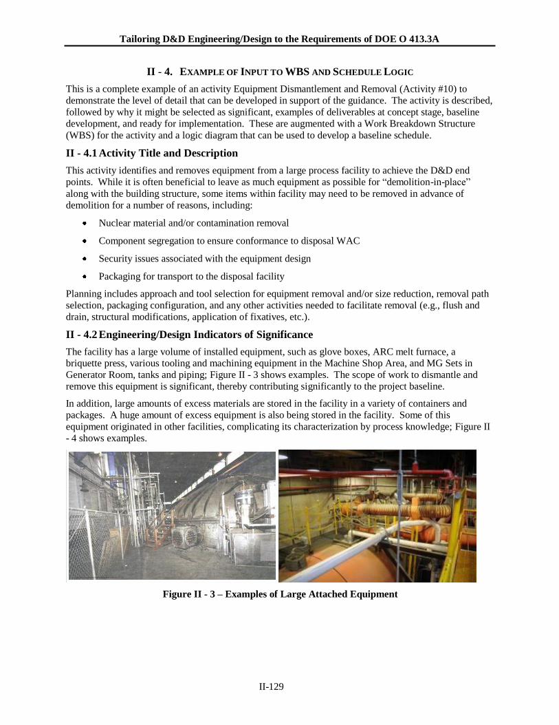
Tailoring D&D Engineering/Design to the Requirements of DOE O 413.3A
II-129
II - 4. EXAMPLE OF INPUT TO WBS AND SCHEDULE LOGIC
This is a complete example of an activity Equipment Dismantlement and Removal (Activity #10) to
demonstrate the level of detail that can be developed in support of the guidance. The activity is described,
followed by why it might be selected as significant, examples of deliverables at concept stage, baseline
development, and ready for implementation. These are augmented with a Work Breakdown Structure
(WBS) for the activity and a logic diagram that can be used to develop a baseline schedule.
II - 4.1 Activity Title and Description
This activity identifies and removes equipment from a large process facility to achieve the D&D end
points. While it is often beneficial to leave as much equipment as possible for “demolition-in-place”
along with the building structure, some items within facility may need to be removed in advance of
demolition for a number of reasons, including:
Nuclear material and/or contamination removal
Component segregation to ensure conformance to disposal WAC
Security issues associated with the equipment design
Packaging for transport to the disposal facility
Planning includes approach and tool selection for equipment removal and/or size reduction, removal path
selection, packaging configuration, and any other activities needed to facilitate removal (e.g., flush and
drain, structural modifications, application of fixatives, etc.).
II - 4.2 Engineering/Design Indicators of Significance
The facility has a large volume of installed equipment, such as glove boxes, ARC melt furnace, a briquette press, various tooling and machining equipment in the Machine Shop Area, and MG Sets in
Generator Room, tanks and piping; Figure II - 3 shows examples. The scope of work to dismantle and
remove this equipment is significant, thereby contributing significantly to the project baseline.
In addition, large amounts of excess materials are stored in the facility in a variety of containers and
packages. A huge amount of excess equipment is also being stored in the facility. Some of this
equipment originated in other facilities, complicating its characterization by process knowledge; Figure II
- 4 shows examples.
Figure II - 3 – Examples of Large Attached Equipment
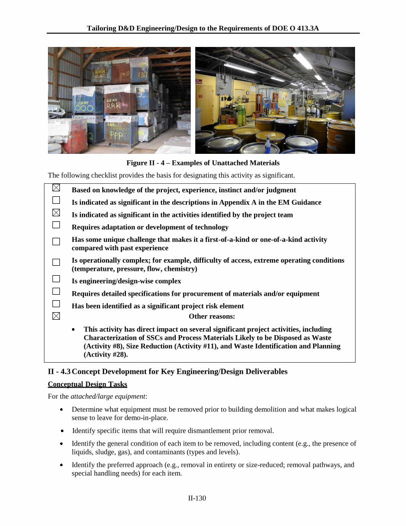
Tailoring D&D Engineering/Design to the Requirements of DOE O 413.3A
II-130
Figure II - 4 – Examples of Unattached Materials
The following checklist provides the basis for designating this activity as significant.
Based on knowledge of the project, experience, instinct and/or judgment
Is indicated as significant in the descriptions in Appendix A in the EM Guidance
Is indicated as significant in the activities identified by the project team
Requires adaptation or development of technology
Has some unique challenge that makes it a first-of-a-kind or one-of-a-kind activity
compared with past experience
Is operationally complex; for example, difficulty of access, extreme operating conditions
(temperature, pressure, flow, chemistry)
Is engineering/design-wise complex
Requires detailed specifications for procurement of materials and/or equipment
Has been identified as a significant project risk element
Other reasons:
This activity has direct impact on several significant project activities, including
Characterization of SSCs and Process Materials Likely to be Disposed as Waste
(Activity #8), Size Reduction (Activity #11), and Waste Identification and Planning
(Activity #28).
II - 4.3 Concept Development for Key Engineering/Design Deliverables
Conceptual Design Tasks
For the attached/large equipment:
Determine what equipment must be removed prior to building demolition and what makes logical
sense to leave for demo-in-place.
Identify specific items that will require dismantlement prior removal.
Identify the general condition of each item to be removed, including content (e.g., the presence of
liquids, sludge, gas), and contaminants (types and levels).
Identify the preferred approach (e.g., removal in entirety or size-reduced; removal pathways, and
special handling needs) for each item.
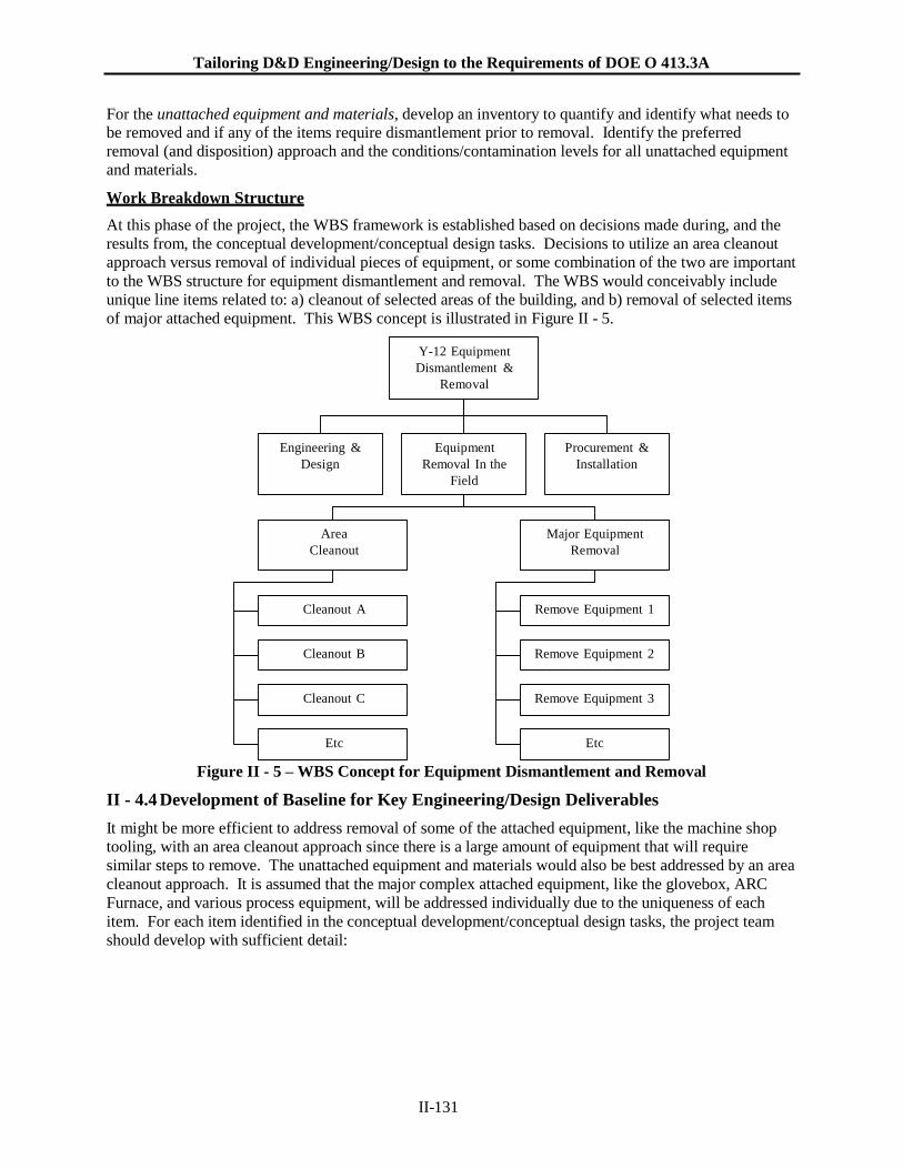
Tailoring D&D Engineering/Design to the Requirements of DOE O 413.3A
II-131
For the unattached equipment and materials, develop an inventory to quantify and identify what needs to be removed and if any of the items require dismantlement prior to removal. Identify the preferred
removal (and disposition) approach and the conditions/contamination levels for all unattached equipment
and materials.
Work Breakdown Structure
At this phase of the project, the WBS framework is established based on decisions made during, and the
results from, the conceptual development/conceptual design tasks. Decisions to utilize an area cleanout
approach versus removal of individual pieces of equipment, or some combination of the two are important
to the WBS structure for equipment dismantlement and removal. The WBS would conceivably include
unique line items related to: a) cleanout of selected areas of the building, and b) removal of selected items
of major attached equipment. This WBS concept is illustrated in Figure II - 5.
Y-12 Equipment
Dismantlement &
Removal
Engineering &
Design
Equipment
Removal In the
Field
Procurement &
Installation
Area
Cleanout
Major Equipment
Removal
Cleanout A Remove Equipment 1
Cleanout B Remove Equipment 2
Cleanout C Remove Equipment 3
Etc Etc
Figure II - 5 – WBS Concept for Equipment Dismantlement and Removal
II - 4.4 Development of Baseline for Key Engineering/Design Deliverables
It might be more efficient to address removal of some of the attached equipment, like the machine shop
tooling, with an area cleanout approach since there is a large amount of equipment that will require
similar steps to remove. The unattached equipment and materials would also be best addressed by an area
cleanout approach. It is assumed that the major complex attached equipment, like the glovebox, ARC
Furnace, and various process equipment, will be addressed individually due to the uniqueness of each
item. For each item identified in the conceptual development/conceptual design tasks, the project team
should develop with sufficient detail:
Tailoring D&D Engineering/Design to the Requirements of DOE O 413.3A
II-132
Equipment Disconnection
Conduct the engineering for disconnection of the equipment from the system/facility where it is located.
This includes addressing electrical connections (e.g., power supply and I&C) and mechanical connections
(e.g., process flow, compressed air, service or cooling water). Disconnection from equipment pedestals
and foundations should also be addressed. Deliverables include:
Work scope for disconnection
Marked-up drawings identifying disconnection locations
Specifications for how each location is to be physically terminated and isolated from it’s source
Test requirements for integrity of terminations and closures
Equipment Draining
Conduct the engineering (as needed) for draining equipment prior to removal (such as oil, cooling water,
process liquids, etc.). Flush and drain operations are further addressed in Activity #12. Deliverables
related to equipment draining prior to removal include:
Identification of drain location
Identification of liquid/sludge removal method
Collection method
Marked-up drawings identifying drain location(s)
Equipment Dismantlement/Disassembly
Conduct the engineering for dismantlement/disassembly of the equipment to facilitate removal (or provide
access to internals for decontamination or removal of residuals). This includes addressing at a component
level-of-detail, the sequence of actions for disassembly and removal and the appropriate type of tools and
fixtures that will be required; and addressing whether fixatives or foaming are required. This also
includes evaluation of the need, and approach to be utilized, for size reduction. Size reduction is further
addressed in Activity #11. Deliverables include:
Work scope for dismantlement/disassembly/size reduction
Equipment drawings
Listing of special tools & fixtures
Sketches of special tools & fixtures
Sequence of dismantlement/disassembly/size reduction actions when important
Rigging and Lifting
Conduct the engineering for rigging and lifting to ensure equipment can be safely removed. This includes
verification of lifting lug capacity (or design of new lifting lugs if needed), identification of rigging
components (e.g., slings and shackles) and special rigging devices (e.g., spreader bar), and lifting zone to
ensure there is no interference from other equipment. Deliverables include:
Calculations for lifting lug design, rigging selection, and crane capacity
Sketches of rigging configuration
Lifting & Rigging Plan
Determination of crane or lifting device (e.g., type, capacity)
Tailoring D&D Engineering/Design to the Requirements of DOE O 413.3A
II-133
Test load requirements
Setup for Characterization
Prepare the engineering associated with the setup for characterization. Given the diversity of equipment
involved and the fact that some of it originated from unknown locations, extensive characterization will
be necessary to plan disassembly and removal activities and to determine appropriate disposition
pathways. Characterization is further addressed in Activity #8. Deliverables include:
Specification of location where characterization is to be conducted
Specification of parameters/radionuclides to be analyzed for
Identification of required characterization equipment
Arrangement drawings
Handling and Transport
Prepare the engineering for handling and transport of the equipment within the facility to verify it can be
safely removed and transported out of the facility (e.g., over floors and/or roofs, through existing passage
ways). This includes addressing packaging needs (or use of fixatives) to control the spread of
contamination. Deliverables include:
Marked up arrangement drawings depicting equipment transport path
Calculations for floor loading analysis
Calculations for modifications to existing passageways or design of new passageways.
Design and specification of contamination control devices/materials
Design of transport cart or dolly, if required.
Design for removal of interferences
Disposition Pathway
Identify the disposition pathway, including appropriate packaging and mode of transport. This activity is
closely related to Waste Identification and Planning which is addressed in Activity #28. Deliverables
include:
Identification of disposal location
Identification of packaging configuration
Identification of transport mode
Functional requirements for special handling, adapters, inserts, contamination isolation
Staffing Requirements
Identify specialized resource needs, such as rigging craft support and structural engineering support, to
ensure availability of personnel with the necessary skills set and to provide input to the development of
the project staffing plan which is needed for the baseline estimate.
II - 4.5 Ready for Implementation for Key Engineering/Design Deliverables
At the start of the CD-3 project phase, it is necessary to only identify the set of procedures that will be
needed to complete the work as detailed in this activity and to specify what these procedures need to
address. The timing for the preparation of the procedures is a project decision and will probably be
deferred until the actual work is to be done.

Tailoring D&D Engineering/Design to the Requirements of DOE O 413.3A
II-134
Engineering at this phase includes:
Completion of all activities that were initiated for CD-2.
Work sequence/installation instructions and engineering requirements input to work packages and
procedures.
Procedure requirements for installation of equipment, materials, and systems.
Procedure requirements for disassembly of identified equipment.
Technical specifications to support procurement for materials, equipment, and services.
II - 4.6 Schedule Relationships
Figure II - 6 shows the logical sequence of activities for this engineering activity. This logic is intended
for use in constructing a critical path schedule.
The interfaces with other engineering activities shown in the diagram include:
Input from: Characterization of SSCs and Process Materials Likely to be Disposed as Waste
(Activity #8) – this information is needed to determine the disassembly and removal approach; to
determine the need for worker PPE, containments, fixatives and other contamination control
measures; and to plan for the disposition for each piece of equipment.
Input from: Deactivation End State & End Points (Activity #2) – the end points for facility
deactivation need to address the extent to which equipment must be removed from the facility
prior to demolition.
Output to: Waste Identification & Planning (Activity #28) – waste generated by removal of
equipment and materials from the building need to be included in waste management planning.
Output to: Size Reduction (Activity #11) – size reduction is closely coupled with equipment
dismantlement and removal and should be iteratively developed with it. The selection of size
reduction approach and tooling is dependant on the type of equipment that must be removed from
the building.
Output to: Several design activities, including rigging, structural modifications, foam/fixatives process, process system isolation, and liquid flush & drain, as needed to facilitate equipment
disassembly and removal from the building.
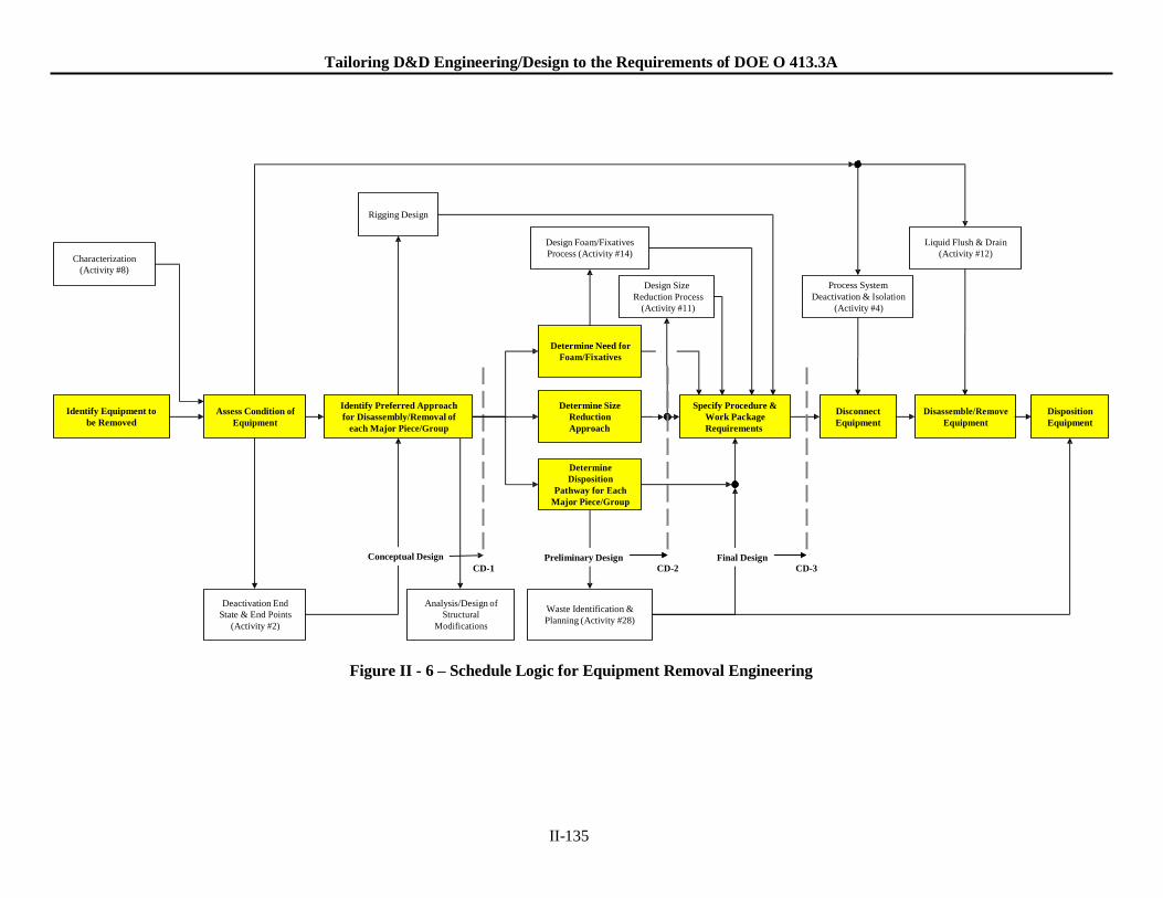
Preliminary Design Final Design
Tailoring D&D Engineering/Design to the Requirements of DOE O 413.3A
Rigging Design
Characterization
(Activity #8)
Design Foam/Fixatives
Process (Activity #14)
Design Size
Process System
Liquid Flush & Drain
(Activity #12)
Reduction Process
(Activity #11)
Deactivation & Isolation
(Activity #4)
Determine Need for
Foam/Fixatives
Identify Equipment to
be Removed
Assess Condition of
Equipment
Identify Preferred Approach
for Disassembly/Removal of
each Major Piece/Group
Determine Size
Reduction
Approach
Specify Procedure &
Work Package
Requirements
Disconnect
Equipment
Disassemble/Remove
Equipment
Disposition
Equipment
Determine
Disposition
Pathway for Each
Major Piece/Group
Conceptual Design CD-1
Preliminary Design CD-2
Final Design CD-3
Deactivation End
State & End Points
(Activity #2)
Analysis/Design of
Structural
Modifications
Waste Identification &
Planning (Activity #28)
Figure II - 6 – Schedule Logic for Equipment Removal Engineering
II-135