Embed Size (px)
Citation preview
64
Lappeenranta, Finland IMWA 2017Mine Water and Circular Economy
Wolkersdorfer C, Sartz L, Sillanpää M, Häkkinen A (Editors)
Tailings Seepage Paths Mapped using Electric-Based Technology
Cecil Urlich1, Andy Hughes2, Val Gardner3
1AECOM, 1111 3rd Avenue, Suite 1600, Seattle, Washington 98101, USA [email protected]
2Atkins Global, The Wells, 3 -13 Church Street, Epsom, Surrey, KT17 4PF, UK, [email protected]
3Willowstick, 11814 Election Rd, Suite 100, Draper, Utah 84020, USA, [email protected]
Abstract Tailings dams have failed at alarming rates compared to water storage dams. Failures are often due to human-controlled design, construction and operation actions which can result in tailings flows, life and property loss, and negatively impact the environmental, social license, company value and industry sustainability. Several technologies are used to help better understand tailings dams, reduce their failure risk, and add value to tailings management. These include the use of electrical current to find seepage paths under a dam. This paper describes this technology by case studies and how it enabled designs to be updated to reduce the failure risk.
Introduction
Tailings dams and storage facilities are unique and are different to water supply dams for many reasons: they store tailings (waste liability) versus water (resource asset); their con-struction and design evolve as the facility develops and tailings volumes increase while codes, regulations and technologies change; they embrace tailings properties, disposal methods and water management in dam design; and they store tailings in perpetuity.
Properly planned, designed, constructed, operated and maintained tailings dams provide safe and effective tailings storage facility (TSF) structures. Dams are raised by optimizing upstream, centerline and downstream methods to fit site conditions, land constraints and mine operations. TSFs use a host of tailings and water management methods to optimize storage space, reduce operation costs, protect the environment, and maintain indefinite dam stability and safety.
Tailings dams are dynamic structures that grow in size and complexity over their operating life and must be maintained after closure. Their designs evolve with time and not always as originally planned because of global events that mine owners have no control over, to local operation, community, environment, and other challenges.
Evolving designs continue to combine proven existing and new (disrupt mining) technolo-gies to enhance the positive, progressive and collective ability to effectively manage tailings dams and TSFs. For example, several new non-intrusive technologies are now being used to help designers such as a method to identify seepage paths at depth through, under and around tailings dams that helps in the design of TSF and tailings dam stabilizations, expan-sions, and closures.
65
Lappeenranta, Finland IMWA 2017Mine Water and Circular Economy
Wolkersdorfer C, Sartz L, Sillanpää M, Häkkinen A (Editors)
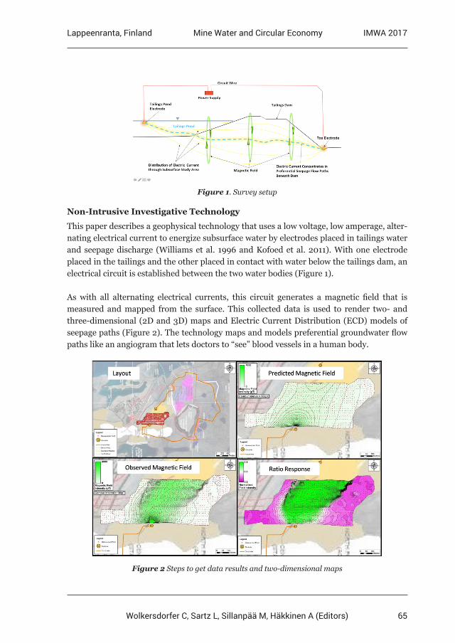
Figure 1. Survey setup
Non-Intrusive Investigative Technology
This paper describes a geophysical technology that uses a low voltage, low amperage, alter-nating electrical current to energize subsurface water by electrodes placed in tailings water and seepage discharge (Williams et al. 1996 and Kofoed et al. 2011). With one electrode placed in the tailings and the other placed in contact with water below the tailings dam, an electrical circuit is established between the two water bodies (Figure 1).
As with all alternating electrical currents, this circuit generates a magnetic field that is measured and mapped from the surface. This collected data is used to render two- and three-dimensional (2D and 3D) maps and Electric Current Distribution (ECD) models of seepage paths (Figure 2). The technology maps and models preferential groundwater flow paths like an angiogram that lets doctors to “see” blood vessels in a human body.
Figure 2 Steps to get data results and two-dimensional maps
66
Lappeenranta, Finland IMWA 2017Mine Water and Circular Economy
Wolkersdorfer C, Sartz L, Sillanpää M, Häkkinen A (Editors)
The application of the technology to tailings dams is based on the principle that water in-creases the conductivity of earth materials through which it flows. As the signature electric current travels between electrodes strategically placed upstream and downstream of the tailings dam, it concentrates in the more conductive zones, or highest transport porosity areas, where tailings water preferentially flows out of the TSF as seepage through, under, and around the dam.
An electric circuit is established in the water of interest. Measuring the resultant magnet-ic field at the surface reveals the electric current flow and distribution. Data is processed and compared to a predicted magnetic field from a theoretical homogenous earth model to highlight deviations from the “uniform” model. 2D maps and 3D models are generated and combined with known sub-surface data to enhance preferential seepage path definitions (Figure 2).
The graphic shading in the following black-and-white figures is shades of gray. Actual sur-vey report graphics range from purple (dark gray) to green (medium gray). Dark gray shows actual flow that is less than flow predicted by the “uniform” model. Medium gray shows actual flow that is more than flow predicted by the “uniform” model, so it likely represents a seepage path.
This paper uses three tailings dam studies to illustrate the procedures, findings and bene-fits of this technology. Results range from confirming design decisions to identifying new seepage paths. In the latter case, designs were updated based on new data in line with the observational approach (Peck 1969) to provide a more safe and stable tailings dam and reduce risk of failure.
Tailings Dam Study 1
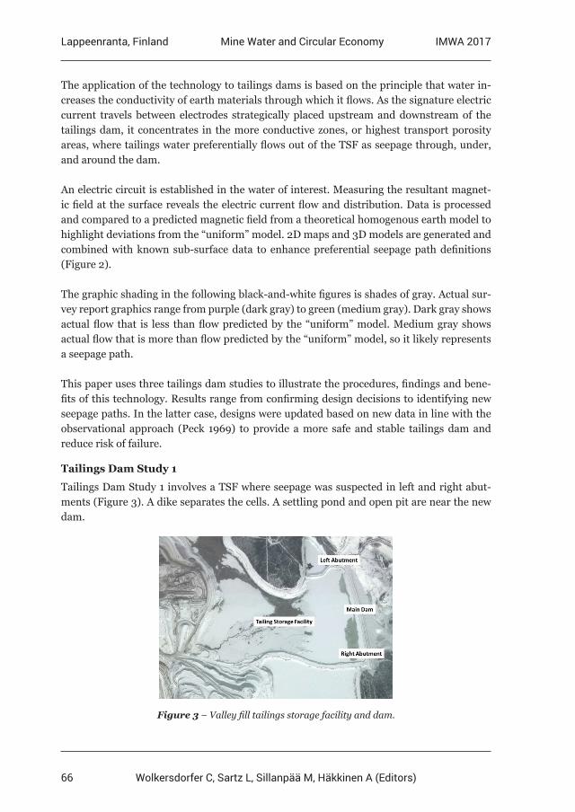
Tailings Dam Study 1 involves a TSF where seepage was suspected in left and right abut-ments (Figure 3). A dike separates the cells. A settling pond and open pit are near the new dam.
Figure 3 – Valley fill tailings storage facility and dam.
67
Lappeenranta, Finland IMWA 2017Mine Water and Circular Economy
Wolkersdorfer C, Sartz L, Sillanpää M, Häkkinen A (Editors)
Seepage had been observed at both right and left abutments of the main dam. The seepage flow was not excessive and there was no sign of turbidity. However, the mine decided to investigate further using the electrical-based technology due to its non-intrusive nature and ability to identify the full seepage pathway in plan and elevation.
Six surveys were planned, three each in the left and right abutment areas. Each survey used a slightly different electrode placement on the tailings side of the dam while the electrode downgradient of the crest remained static for each set of three surveys. Each survey covered a different geography with overlap between surveys to confirm any observed anomalies.
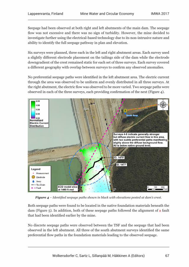
No preferential seepage paths were identified in the left abutment area. The electric current through the area was observed to be uniform and evenly distributed in all three surveys. At the right abutment, the electric flow was observed to be more varied. Two seepage paths were observed in each of the three surveys, each providing confirmation of the next (Figure 4).
Figure 4 – Identified seepage paths shown in black with elevations posted at dam’s crest.
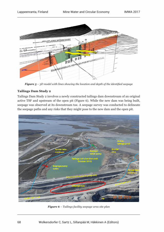
Both seepage paths were found to be located in the native foundation materials beneath the dam (Figure 5). In addition, both of these seepage paths followed the alignment of a fault that had been identified earlier by the mine.
No discrete seepage paths were observed between the TSF and the seepage that had been observed in the left abutment. All three of the south abutment surveys identified the same preferential flow paths in the foundation materials leading to the observed seepage.
68
Lappeenranta, Finland IMWA 2017Mine Water and Circular Economy
Wolkersdorfer C, Sartz L, Sillanpää M, Häkkinen A (Editors)
Figure 5 – 3D model with lines showing the location and depth of the identified seepage
Tailings Dam Study 2
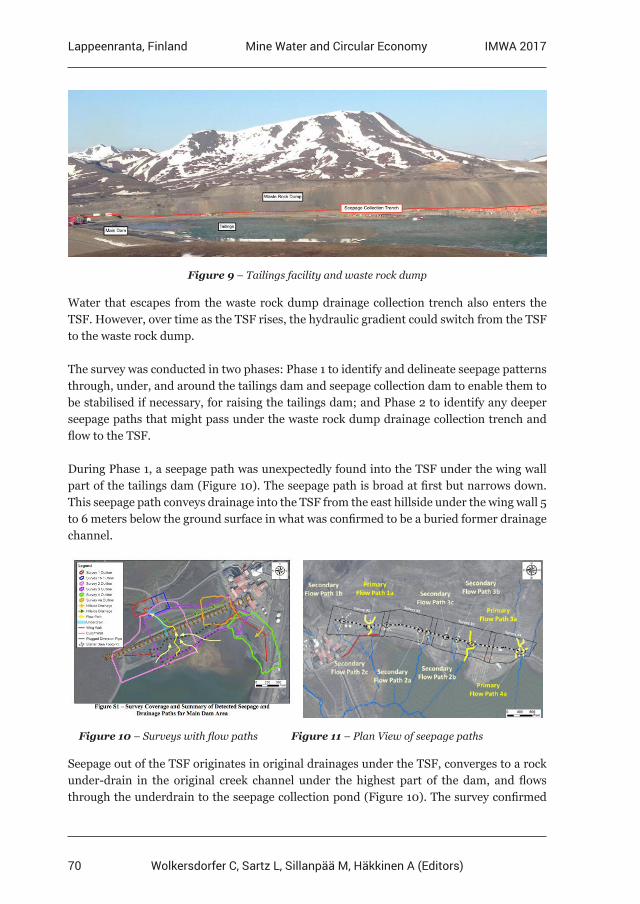
Tailings Dam Study 2 involves a newly constructed tailings dam downstream of an original active TSF and upstream of the open pit (Figure 6). While the new dam was being built, seepage was observed at its downstream toe. A seepage survey was conducted to delineate the seepage paths and any risks that they might pose to the new dam and the open pit.
Figure 6 – Tailings facility seepage area site plan

69
Lappeenranta, Finland IMWA 2017Mine Water and Circular Economy
Wolkersdorfer C, Sartz L, Sillanpää M, Häkkinen A (Editors)
Two survey layouts were used with the same upstream electrode in the new tailings pond. For Survey 1, the downstream electrode was in the seepage discharge at the toe of the new dam. For Survey 2, it was in the seepage discharge in the open pit east of the dam.
Survey 1 identified primary and secondary seepage paths under the dam (Figures 7 and 8). The plan and profile views show seepage path widths and depths. The green (medium gray) shading indicates seepage paths. The black lines are interpretations of seepage paths between the two electrodes.
Figure 7 – Two seepage paths under dam Figure 8 – Seepage path elevations
The results confirmed that there are no other seepage paths of any significance through or under the dam. This provided confidence that piping and internal erosion were not con-cerns for the dam itself because the identified seepage paths are in the foundation materials under the dam and not in the dam structure itself. So the geotechnical investigations for piping potential could be focused on the foundation materials under the dam and not on the dam structure itself.
A geotechnical investigation was completed by drilling into the seepage path target areas identified by the survey. The drilling confirmed the survey findings. Remedial measures are now being planned that will be significantly less in cost than if the survey had not been completed and seepage paths not found because the investigation was targeted on the areas of concern.
Tailings Dam Study 3
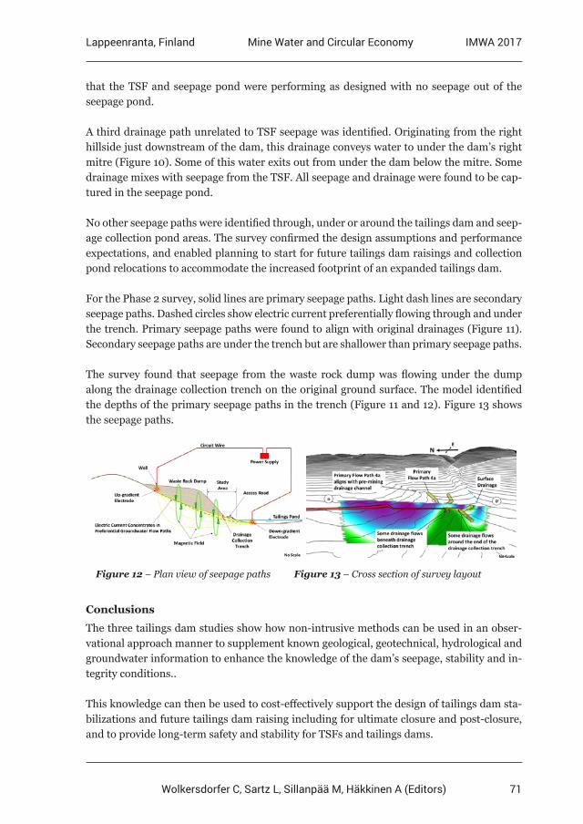
Tailings Dam Study 3 involves a TSF with a tailings dam in a valley. A seepage collection pond is downstream of the tailings dam. A waste rock dump occupies one of the valley sides of the TSF. A 2-kilometer long drainage collection trench is aligned along the toe of this dump (Figure 9).
Seepage from the TSF collects in a collection system and is pumped back to the TSF. Addi-tional contribution to the pumped back water is surface runoff from the collection system catchment area. There was concern that some “surface runoff” could also be seepage from the TSF through the left abutment of the tailings dam, and that there could be seepage from the TSF flowing under the collection system and to the environment.
70
Lappeenranta, Finland IMWA 2017Mine Water and Circular Economy
Wolkersdorfer C, Sartz L, Sillanpää M, Häkkinen A (Editors)
Figure 9 – Tailings facility and waste rock dump
Water that escapes from the waste rock dump drainage collection trench also enters the TSF. However, over time as the TSF rises, the hydraulic gradient could switch from the TSF to the waste rock dump.
The survey was conducted in two phases: Phase 1 to identify and delineate seepage patterns through, under, and around the tailings dam and seepage collection dam to enable them to be stabilised if necessary, for raising the tailings dam; and Phase 2 to identify any deeper seepage paths that might pass under the waste rock dump drainage collection trench and flow to the TSF.
During Phase 1, a seepage path was unexpectedly found into the TSF under the wing wall part of the tailings dam (Figure 10). The seepage path is broad at first but narrows down. This seepage path conveys drainage into the TSF from the east hillside under the wing wall 5 to 6 meters below the ground surface in what was confirmed to be a buried former drainage channel.
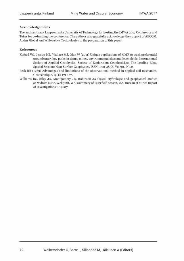
Figure 10 – Surveys with flow paths Figure 11 – Plan View of seepage paths
Seepage out of the TSF originates in original drainages under the TSF, converges to a rock under-drain in the original creek channel under the highest part of the dam, and flows through the underdrain to the seepage collection pond (Figure 10). The survey confirmed
71
Lappeenranta, Finland IMWA 2017Mine Water and Circular Economy
Wolkersdorfer C, Sartz L, Sillanpää M, Häkkinen A (Editors)
that the TSF and seepage pond were performing as designed with no seepage out of the seepage pond.
A third drainage path unrelated to TSF seepage was identified. Originating from the right hillside just downstream of the dam, this drainage conveys water to under the dam’s right mitre (Figure 10). Some of this water exits out from under the dam below the mitre. Some drainage mixes with seepage from the TSF. All seepage and drainage were found to be cap-tured in the seepage pond.
No other seepage paths were identified through, under or around the tailings dam and seep-age collection pond areas. The survey confirmed the design assumptions and performance expectations, and enabled planning to start for future tailings dam raisings and collection pond relocations to accommodate the increased footprint of an expanded tailings dam.
For the Phase 2 survey, solid lines are primary seepage paths. Light dash lines are secondary seepage paths. Dashed circles show electric current preferentially flowing through and under the trench. Primary seepage paths were found to align with original drainages (Figure 11). Secondary seepage paths are under the trench but are shallower than primary seepage paths.
The survey found that seepage from the waste rock dump was flowing under the dump along the drainage collection trench on the original ground surface. The model identified the depths of the primary seepage paths in the trench (Figure 11 and 12). Figure 13 shows the seepage paths.
Figure 12 – Plan view of seepage paths Figure 13 – Cross section of survey layout
Conclusions
The three tailings dam studies show how non-intrusive methods can be used in an obser-vational approach manner to supplement known geological, geotechnical, hydrological and groundwater information to enhance the knowledge of the dam’s seepage, stability and in-tegrity conditions..
This knowledge can then be used to cost-effectively support the design of tailings dam sta-bilizations and future tailings dam raising including for ultimate closure and post-closure, and to provide long-term safety and stability for TSFs and tailings dams.
72
Lappeenranta, Finland IMWA 2017Mine Water and Circular Economy
Wolkersdorfer C, Sartz L, Sillanpää M, Häkkinen A (Editors)
Acknowledgements
The authors thank Lappeenranta University of Technology for hosting the IMWA 2017 Conference and Tekes for co-funding the conference. The authors also gratefully acknowledge the support of AECOM, Atkins Global and Willowstick Technologies in the preparation of this paper.
References
Kofoed VO, Jessup ML, Wallace MJ, Qian W (2011) Unique applications of MMR to track preferential groundwater flow paths in dams, mines, environmental sites and leach fields. International Society of Applied Geophysics, Society of Exploration Geophysicists, The Leading Edge, Special Session: Near Surface Geophysics, ISSN 1070-485X, Vol 30., No.2.Peck RB (1969) Advantages and limitations of the observational method in applied soil mechanics. Geotechnique, 19(1): 171-187.Williams BC, Riley JA, Montgomery JR, Robinson JA (1996) Hydrologic and geophysical studies at Midnite Mine, Wellpinit, WA: Summary of 1995 field season, U.S. Bureau of Mines Report of Investigations R 19607