Embed Size (px)
Citation preview
- 147 -
Tail Gas SO2 Scrubbing using fluidized Bed Technology
KIM NIKOLAISEN*1, ANDRÉS MAHECHA-BOTERO
NORAM Engineering and Constructors Ltd Vancouver, Canada
DAVID MISSIONS
Osprey Corporation Kent, UK
HOWARD DAVIS
Fluid Technologies (Environmental) Ltd Surrey, UK
Many sulphuric acid plants around the world are facing increased pressure from environmental agencies and stakeholders to reduce emissions in the form of SO2 and sometimes H2SO4. It is the standard to measure and report these emissions during continuous operation, but many producers are also experiencing increasingly stringent emission targets for the duration of plant start-up. During plant start-up many plants experience spikes in SO2 concentrations, and the “blue smoke” or stack opacity from SO3 slippage can be another concern.
Tail gas scrubbing processes are a proven way of reducing SO2 emissions during both continuous and start-up operations. However, most scrubbing technologies will only remove SO2 and may have to rely on additional downstream technologies such as high-efficiency Brownian diffusion mist eliminators or wet electro static precipitators (WESPs) to remove fine acid mist aerosols i.e. “blue smoke”. The TurboScrubber® fluidized bed technology, licensed by NORAM,
1 Corresponding author. email: [email protected]
K. Nikolaisen, D. Missions, H. Davis, A. Mahecha-Botero
148 Sulphur 2013 International Conference (Miami, USA 4-7 November 2013)
has been successfully applied to a wide range of SO2 scrubbing applications, and can potentially be used with great effect in the sulphuric acid industry. Significantly, NORAM’s TurboScrubber® system provides a means of removing both SO2 and acid mist efficiently in one single process unit. The aerosol removal capability is achieved through an extremely energetic mixing of tail gas and scrubbing liquid.
NORAM’s TurboScrubber® technology has inherently higher mass and heat transfer rates for a given gas-side pressure drop, as compared to other gas-liquid contacting technologies (e.g. packed towers, venturis, reverse-jet). This higher mass transfer rate results in a smaller equipment footprint and lower capital investment. The scrubber works with all traditional scrubbing media (eg. NaOH/Na2CO3, H2O2, NH3, sea water), and can also handle slurries owing to the non-fouling nature of its fluidized bed. This slurry compatibility opens the door for using alternative scrubbing media such as limestone/hydrated lime, from which the scrubbing product, CaSO4, may be disposed of in existing gypsum piles.
An interesting feature of NORAM’s TurboScrubber® technology is its process flexibility. For example, the scrubber can handle gas turndown rates of up to 1:12, and the efficiency of both SO2 and acid mist aerosol removal can variably be increased during plant turndown and start-up operations. The TurboScrubber also has merit in efficiently removing acid spray/mist carryover from the upstream Final Absorption Tower. Hence, NORAM’s TurboScrubber® process offers the possibilities of SO2 emission reduction, “blue smoke” aerosol mist removal, acid mist/spray carryover removal, continuous and start-up emission reductions, and the use of scrubbing slurries - all achievable in one process unit operation, with a lower capital cost and smaller foot print than other scrubbing technologies.
Keywords: Sulphur dioxide, acid mist, blue smoke, blue haze, tail gas, scrubbing, plant start-up, fluidized bed, pollution control
INTRODUCTION Many sulphuric acid plants around the world are facing increased pressure from environmental agencies and/or stakeholders to reduce emissions in the form of SO2 and sometimes acid mist and “blue smoke”. It is the standard to measure and report these emissions during continuous operation, but many producers are also experiencing increasingly stringent emission targets for the duration of plant start-up. During plant start-up many plants experience spikes in SO2 concentrations, and a “blue smoke” or stack opacity from SO3 slippage can be of concern. Tail gas scrubbing processes are a proven way of reducing SO2 emissions, during both continuous and start-up operations. However, most scrubbing technologies will only remove SO2 and must rely on additional downstream technologies such as high-efficiency Brownian diffusion (BD) mist eliminators or wet electro static precipitators (WESPs) to remove fine acid mist aerosols i.e. “blue smoke”. In this paper we propose the use of NORAM’s TurboScrubber®. This is a proven fluidized bed scrubbing technology, which allows the use of all standard scrubbing chemicals (eg. NaOH/Na2CO3, H2O2, NH3, amines, sea water), and also handles slurries such as limestone/hydrated lime (e.g. CaCO3, Ca(OH)2, Mg(OH)2). Furthermore, this fluidized bed technology has inherent particle/mist removal capabilities, which results in the possibility to remove both SO2 and acid mist/”blue smoke” in one single process unit.
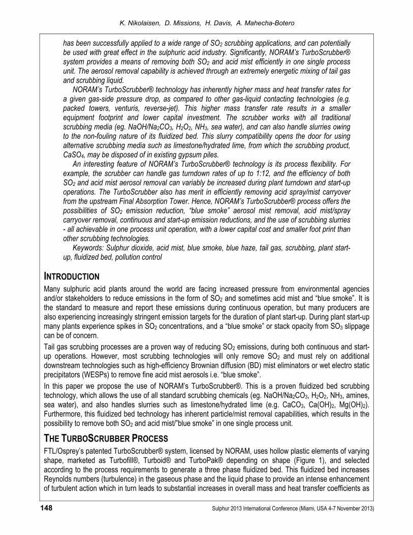
THE TURBOSCRUBBER PROCESS FTL/Osprey’s patented TurboScrubber® system, licensed by NORAM, uses hollow plastic elements of varying shape, marketed as Turbofill®, Turboid® and TurboPak® depending on shape (Figure 1), and selected according to the process requirements to generate a three phase fluidized bed. This fluidized bed increases Reynolds numbers (turbulence) in the gaseous phase and the liquid phase to provide an intense enhancement of turbulent action which in turn leads to substantial increases in overall mass and heat transfer coefficients as

Tail Gas SO2 Scrubbing using fluidized Bed Technology
Sulphur 2013 International Conference (Miami, USA 4-7 November 2013) 149
well as interphase surface renewal rates as compared to classical packings and other scrubbing technologies (see next section). Figure 2 shows images of the fluidized bed.
Fig. 1: Photos of the two main packing elements ; Left: Turboid®; Right: TurboPak®
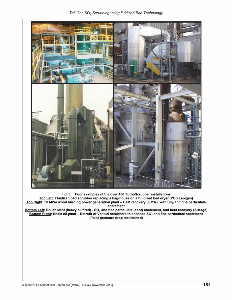
In addition, the fluidized bed simultaneously removes particulates down to very fine sub-half-micron diameters (<0.5 µm). System design varies from application to application as process operations or pollution control needs vary widely. When very hot gases are to be treated and cleaned using the TurboScrubber® technology they are first passed through a quench chamber which is usually integrated with the scrubber such that quenching can occur in two steps using both the inlet quench section and a specially designed sump to maximum effect. The cooled gases then enter the fluidized bed where ascending gas is intimately mixed by the fluidized packing elements with the descending and usually recirculated liquid. The TurboScrubber® system allows operation with slurries, mud and oily or viscous liquids due to the 100% non-clogging nature of the fluidized bed. The system is also highly versatile operating with highly variable flows and conditions. TurboScrubber® fluid bed technology is employed by process operators to clean gases for mining & minerals, boiler & incinerator, pyrolysis & gasification, food production, power generation & fuel cells, chemical & petrochemical plants. TurboScrubber’s unique value is that it simultaneously absorbs toxic gases, removes very fine particulate and recovers energy in a single compact unit. Figure 3 shows four examples of the over 100 TurboScrubber installations and gives a flavour of its application.
K. Nikolaisen, D. Missions, H. Davis, A. Mahecha-Botero
150 Sulphur 2013 International Conference (Miami, USA 4-7 November 2013)
Fig. 2: Sketch of TurboScrubber tower indicating flows and turbulent action along with an image showing the
general arrangement of the TurboScrubber tower
Gas FlowGas Flow
Tail Gas SO2 Scrubbing using fluidized Bed Technology
Sulphur 2013 International Conference (Miami, USA 4-7 November 2013) 151
Fig. 3: Four examples of the over 100 TurboScrubber installations Top Left: Fluidized bed scrubber replacing a bag-house on a fluidized bed dryer (PCS Lanigan)
Top Right: 30 MWe wood burning power generation plant – Heat recovery (9 MW), with SO2 and fine particulate abatement
Bottom Left: Boiler plant (heavy oil fired) - SO2 and fine particulate (soot) abatement, and heat recovery (2-stage) Bottom Right: Shale oil plant – Retrofit of Venturi scrubbers to enhance SO2 and fine particulate abatement
(Plant pressure drop maintained)
K. Nikolaisen, D. Missions, H. Davis, A. Mahecha-Botero
152 Sulphur 2013 International Conference (Miami, USA 4-7 November 2013)
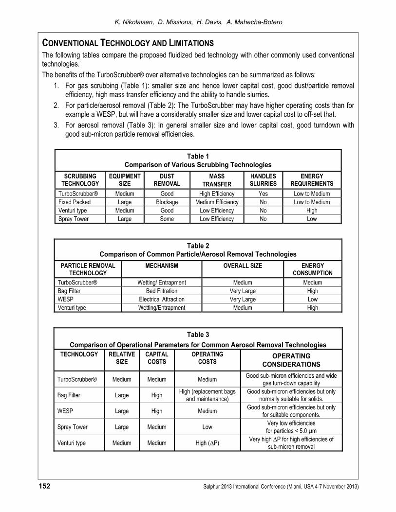
CONVENTIONAL TECHNOLOGY AND LIMITATIONS The following tables compare the proposed fluidized bed technology with other commonly used conventional technologies. The benefits of the TurboScrubber® over alternative technologies can be summarized as follows:
1. For gas scrubbing (Table 1): smaller size and hence lower capital cost, good dust/particle removal efficiency, high mass transfer efficiency and the ability to handle slurries.
2. For particle/aerosol removal (Table 2): The TurboScrubber may have higher operating costs than for example a WESP, but will have a considerably smaller size and lower capital cost to off-set that.
3. For aerosol removal (Table 3): In general smaller size and lower capital cost, good turndown with good sub-micron particle removal efficiencies.
Table 1
Comparison of Various Scrubbing Technologies
SCRUBBING TECHNOLOGY
EQUIPMENT SIZE
DUST REMOVAL
MASS TRANSFER
HANDLES SLURRIES
ENERGY REQUIREMENTS
TurboScrubber® Medium Good High Efficiency Yes Low to Medium Fixed Packed Large Blockage Medium Efficiency No Low to Medium Venturi type Medium Good Low Efficiency No High Spray Tower Large Some Low Efficiency No Low
Table 2 Comparison of Common Particle/Aerosol Removal Technologies
PARTICLE REMOVAL TECHNOLOGY
MECHANISM OVERALL SIZE ENERGY CONSUMPTION
TurboScrubber® Wetting/ Entrapment Medium Medium Bag Filter Bed Filtration Very Large High WESP Electrical Attraction Very Large Low Venturi type Wetting/Entrapment Medium High
Table 3
Comparison of Operational Parameters for Common Aerosol Removal Technologies TECHNOLOGY RELATIVE
SIZE CAPITAL COSTS
OPERATING COSTS
OPERATING CONSIDERATIONS
TurboScrubber® Medium Medium Medium Good sub-micron efficiencies and wide
gas turn-down capability
Bag Filter Large High High (replacement bags and maintenance)
Good sub-micron efficiencies but only normally suitable for solids.
WESP Large High Medium Good sub-micron efficiencies but only
for suitable components.
Spray Tower Large Medium Low Very low efficiencies for particles < 5.0 µm
Venturi type Medium Medium High (∆P) Very high ∆P for high efficiencies of
sub-micron removal
Tail Gas SO2 Scrubbing using fluidized Bed Technology
Sulphur 2013 International Conference (Miami, USA 4-7 November 2013) 153
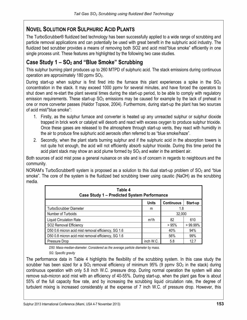
NOVEL SOLUTION FOR SULPHURIC ACID PLANTS The TurboScrubber® fluidized bed technology has been successfully applied to a wide range of scrubbing and particle removal applications and can potentially be used with great benefit in the sulphuric acid industry. The fluidized bed scrubber provides a means of removing both SO2 and acid mist/“blue smoke” efficiently in one single process unit. These features are highlighted by the following two case studies.
Case Study 1 – SO2 and “Blue Smoke” Scrubbing This sulphur burning plant produces up to 260 MTPD of sulphuric acid. The stack emissions during continuous operation are approximately 180 ppmv SO2. During start-up when sulphur is first fired into the furnace this plant experiences a spike in the SO2 concentration in the stack. It may exceed 1000 ppmv for several minutes, and have forced the operators to shut down and re-start the plant several times during the start-up period, to be able to comply with regulatory emission requirements. These start-up SO2 emissions may be caused for example by the lack of preheat in one or more converter passes (Haldor Topsoe, 2004). Furthermore, during start-up the plant has two sources of acid mist/”blue smoke”:
1. Firstly, as the sulphur furnace and converter is heated up any unreacted sulphur or sulphur dioxide trapped in brick work or catalyst will desorb and react with excess oxygen to produce sulphur trioxide. Once these gases are released to the atmosphere through start-up vents, they react with humidity in the air to produce fine sulphuric acid aerosols often referred to as “blue smoke/haze”.
2. Secondly, when the plant starts burning sulphur and if the sulphuric acid in the absorption towers is not quite hot enough, the acid will not efficiently absorb sulphur trioxide. During this time period the acid plant stack may show an acid plume formed by SO3 and water in the ambient air.
Both sources of acid mist pose a general nuisance on site and is of concern in regards to neighbours and the community. NORAM’s TurboScrubber® system is proposed as a solution to this dual start-up problem of SO2 and “blue smoke”. The core of the system is the fluidized bed scrubbing tower using caustic (NaOH) as the scrubbing media.
Table 4 Case Study 1 – Predicted System Performance
Units Continuous Start-up TurboScrubber Diameter m 1.8 Number of Turboids 32,000
Liquid Circulation Rate m3/h 82 610 SO2 Removal Efficiency > 95% > 99.99% D50 0.6 micron acid mist removal efficiency, SG 1.6 40% 94% D50 0.8 micron acid mist removal efficiency, SG 1.6 56% 99% Pressure Drop inch W.C. 5.8 12.7
D50: Mass-median-diameter. Considered as the average particle diameter by mass.
SG: Specific gravity
The performance data in Table 4 highlights the flexibility of the scrubbing system. In this case study the scrubber has been sized for a SO2 removal efficiency of minimum 95% (9 ppmv SO2 in the stack) during continuous operation with only 5.8 inch W.C. pressure drop. During normal operation the system will also remove sub-micron acid mist with an efficiency of 40-55%. During start-up, when the plant gas flow is about 55% of the full capacity flow rate, and by increasing the scrubbing liquid circulation rate, the degree of turbulent mixing is increased considerably at the expense of 7 inch W.C. of pressure drop. However, this
K. Nikolaisen, D. Missions, H. Davis, A. Mahecha-Botero
154 Sulphur 2013 International Conference (Miami, USA 4-7 November 2013)
pressure drop is readily available during start-up due to the low gas flow rate. The increased turbulence of the fluidized bed results in a predicted acid mist removal of more than 94%. The efficiency of acid mist removal depends not only on the liquid flow rate and pressure drop, but also on the inherent properties of the “acid mist particle” such as the particle size and the specific gravity. The exact values for these particle parameters are not known for the plant considered. To be conservative the specific gravity was assumed to be 1.6 similar to that of 75 wt% sulphuric acid at process temperature. Also, it is known that some of the smallest mist particles in an acid plant are generated in an interpass tower with oleum production due to gas quenching and high local SO3 vapour pressures. In these towers the minimum acid mist particle size is about 0.3 micron. In a normal Final Absorption Tower the acid mist particle mean size is about 1.5 micron (Louie, 2008). In the performance predictions above a median acid mist particle size of 0.6 or 0.8 micron was used, which is an order of magnitude smaller than the expected mean size from the upstream FAT. Therefore, it is reasonable to expect even higher removal efficiencies than reported in Table 4. It is also worth noting that the increased turbulence and residence time of the scrubber increases the SO2 removal efficiency to more than 99.99% during start-up.
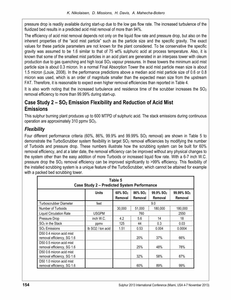
Case Study 2 – SO2 Emission Flexibility and Reduction of Acid Mist Emissions This sulphur burning plant produces up to 600 MTPD of sulphuric acid. The stack emissions during continuous operation are approximately 310 ppmv SO2.
Flexibility Four different performance criteria (60%, 86%, 99.9% and 99.99% SO2 removal) are shown in Table 5 to demonstrate the TurboScrubber system flexibility in target SO2 removal efficiencies by modifying the number of Turboids and pressure drop. These numbers illustrate how the scrubbing system can be built for 60% removal efficiency, and at a later date, the removal efficiency can be improved without any physical changes to the system other than the easy addition of more Turboids or increased liquid flow rate. With a 6-7 inch W.C. pressure drop the SO2 removal efficiency can be improved significantly to >99% efficiency. This flexibility of the installed scrubbing system is a unique feature of the TurboScrubber, which cannot be attained for example with a packed bed scrubbing tower.
Table 5 Case Study 2 – Predicted System Performance
Units 60% SO2 86% SO2 99.9% SO2 99.99% SO2 Removal Removal Removal Removal
Turboscrubber Diameter feet 9.0 Number of Turboids 30,000 51,000 180,000 180,000 Liquid Circulation Rate USGPM 760 2550 Pressure Drop inch W.C. 4.2 5.6 14 18 SO2 in the Stack ppmv 125 44 0.3 0.03 SO2 Emissions lb SO2 / ton acid 1.51 0.53 0.004 0.0004 D50 0.4 micron acid mist removal efficiency, SG 1.6 20% 37% 66% D50 0.5 micron acid mist removal efficiency, SG 1.6 25% 48% 78% D50 0.6 micron acid mist removal efficiency, SG 1.6 32% 58% 87% D50 1.0 micron acid mist removal efficiency, SG 1.6 60% 89% 99%
Tail Gas SO2 Scrubbing using fluidized Bed Technology
Sulphur 2013 International Conference (Miami, USA 4-7 November 2013) 155
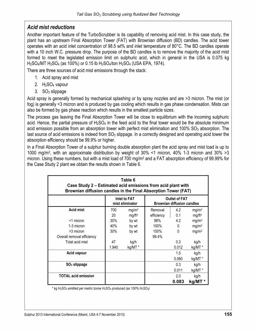
Acid mist reductions Another important feature of the TurboScrubber is its capability of removing acid mist. In this case study, the plant has an upstream Final Absorption Tower (FAT) with Brownian diffusion (BD) candles. The acid tower operates with an acid inlet concentration of 98.5 wt% and inlet temperature of 80°C. The BD candles operate with a 10 inch W.C. pressure drop. The purpose of the BD candles is to remove the majority of the acid mist formed to meet the legislated emission limit on sulphuric acid, which in general in the USA is 0.075 kg H2SO4/MT H2SO4 (as 100%) or 0.15 lb H2SO4/ton H2SO4 (USA EPA, 1974). There are three sources of acid mist emissions through the stack:
1. Acid spray and mist 2. H2SO4 vapour 3. SO3 slippage
Acid spray is generally formed by mechanical splashing or by spray nozzles and are >3 micron. The mist (or fog) is generally <3 micron and is produced by gas cooling which results in gas phase condensation. Mists can also be formed by gas phase reaction which results in the smallest particle sizes. The process gas leaving the Final Absorption Tower will be close to equilibrium with the incoming sulphuric acid. Hence, the partial pressure of H2SO4 in the feed acid to the final tower would be the absolute minimum acid emission possible from an absorption tower with perfect mist elimination and 100% SO3 absorption. The last source of acid emissions is indeed from SO3 slippage. In a correctly designed and operating acid tower the absorption efficiency should be 99.9% or higher. In a Final Absorption Tower of a sulphur burning double absorption plant the acid spray and mist load is up to 1000 mg/m3, with an approximate distribution by weight of 30% <1 micron, 40% 1-3 micron and 30% >3 micron. Using these numbers, but with a mist load of 700 mg/m3 and a FAT absorption efficiency of 99.99% for the Case Study 2 plant we obtain the results shown in Table 6.
Table 6 Case Study 2 – Estimated acid emissions from acid plant with
Brownian diffusion candles in the Final Absorption Tower (FAT)
Inlet to FAT mist eliminator
Outlet of FAT Brownian diffusion candles
Acid mist 700 mg/m3 Removal 4.2 mg/m3 20 mg/ft3 efficiency 0.1 mg/ft3
<1 micron 30% by wt 98% 4.2 mg/m3 1-3 micron 40% by wt 100% 0 mg/m3 >3 micron 30% by wt 100% 0 mg/m3
Overall removal efficiency 99.4% Total acid mist 47 kg/h 0.3 kg/h
1.940 kg/MT * 0.012 kg/MT * Acid vapour 1.5 kg/h
0.060 kg/MT * SO3 slippage 0.3 kg/h
0.011 kg/MT * TOTAL acid emission 2.0 kg/h
0.083 kg/MT *
* kg H2SO4 emitted per metric tonne H2SO4 produced (as 100% H2SO4)
K. Nikolaisen, D. Missions, H. Davis, A. Mahecha-Botero
156 Sulphur 2013 International Conference (Miami, USA 4-7 November 2013)
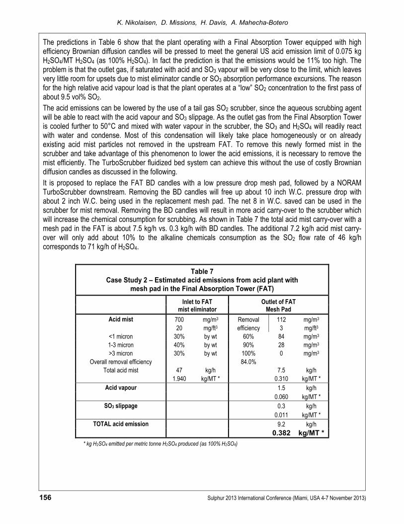
The predictions in Table 6 show that the plant operating with a Final Absorption Tower equipped with high efficiency Brownian diffusion candles will be pressed to meet the general US acid emission limit of 0.075 kg H2SO4/MT H2SO4 (as 100% H2SO4). In fact the prediction is that the emissions would be 11% too high. The problem is that the outlet gas, if saturated with acid and SO3 vapour will be very close to the limit, which leaves very little room for upsets due to mist eliminator candle or SO3 absorption performance excursions. The reason for the high relative acid vapour load is that the plant operates at a “low” SO2 concentration to the first pass of about 9.5 vol% SO2. The acid emissions can be lowered by the use of a tail gas SO2 scrubber, since the aqueous scrubbing agent will be able to react with the acid vapour and SO3 slippage. As the outlet gas from the Final Absorption Tower is cooled further to 50°C and mixed with water vapour in the scrubber, the SO3 and H2SO4 will readily react with water and condense. Most of this condensation will likely take place homogeneously or on already existing acid mist particles not removed in the upstream FAT. To remove this newly formed mist in the scrubber and take advantage of this phenomenon to lower the acid emissions, it is necessary to remove the mist efficiently. The TurboScrubber fluidized bed system can achieve this without the use of costly Brownian diffusion candles as discussed in the following. It is proposed to replace the FAT BD candles with a low pressure drop mesh pad, followed by a NORAM TurboScrubber downstream. Removing the BD candles will free up about 10 inch W.C. pressure drop with about 2 inch W.C. being used in the replacement mesh pad. The net 8 in W.C. saved can be used in the scrubber for mist removal. Removing the BD candles will result in more acid carry-over to the scrubber which will increase the chemical consumption for scrubbing. As shown in Table 7 the total acid mist carry-over with a mesh pad in the FAT is about 7.5 kg/h vs. 0.3 kg/h with BD candles. The additional 7.2 kg/h acid mist carry-over will only add about 10% to the alkaline chemicals consumption as the SO2 flow rate of 46 kg/h corresponds to 71 kg/h of H2SO4.
Table 7 Case Study 2 – Estimated acid emissions from acid plant with
mesh pad in the Final Absorption Tower (FAT)
Inlet to FAT mist eliminator
Outlet of FAT Mesh Pad
Acid mist 700 mg/m3 Removal 112 mg/m3 20 mg/ft3 efficiency 3 mg/ft3
<1 micron 30% by wt 60% 84 mg/m3 1-3 micron 40% by wt 90% 28 mg/m3 >3 micron 30% by wt 100% 0 mg/m3
Overall removal efficiency 84.0% Total acid mist 47 kg/h 7.5 kg/h
1.940 kg/MT * 0.310 kg/MT * Acid vapour 1.5 kg/h
0.060 kg/MT * SO3 slippage 0.3 kg/h
0.011 kg/MT * TOTAL acid emission 9.2 kg/h
0.382 kg/MT *
* kg H2SO4 emitted per metric tonne H2SO4 produced (as 100% H2SO4)
Tail Gas SO2 Scrubbing using fluidized Bed Technology
Sulphur 2013 International Conference (Miami, USA 4-7 November 2013) 157
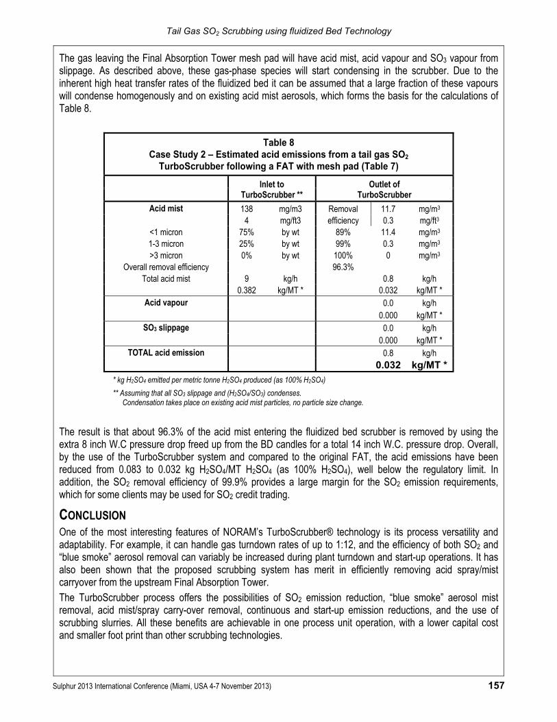
The gas leaving the Final Absorption Tower mesh pad will have acid mist, acid vapour and SO3 vapour from slippage. As described above, these gas-phase species will start condensing in the scrubber. Due to the inherent high heat transfer rates of the fluidized bed it can be assumed that a large fraction of these vapours will condense homogenously and on existing acid mist aerosols, which forms the basis for the calculations of Table 8.
Table 8 Case Study 2 – Estimated acid emissions from a tail gas SO2
TurboScrubber following a FAT with mesh pad (Table 7)
Inlet to TurboScrubber **
Outlet of TurboScrubber
Acid mist 138 mg/m3 Removal 11.7 mg/m3 4 mg/ft3 efficiency 0.3 mg/ft3
<1 micron 75% by wt 89% 11.4 mg/m3 1-3 micron 25% by wt 99% 0.3 mg/m3 >3 micron 0% by wt 100% 0 mg/m3
Overall removal efficiency 96.3% Total acid mist 9 kg/h 0.8 kg/h
0.382 kg/MT * 0.032 kg/MT * Acid vapour 0.0 kg/h
0.000 kg/MT * SO3 slippage 0.0 kg/h
0.000 kg/MT * TOTAL acid emission 0.8 kg/h
0.032 kg/MT *
* kg H2SO4 emitted per metric tonne H2SO4 produced (as 100% H2SO4)
** Assuming that all SO3 slippage and (H2SO4/SO3) condenses. Condensation takes place on existing acid mist particles, no particle size change.
The result is that about 96.3% of the acid mist entering the fluidized bed scrubber is removed by using the extra 8 inch W.C pressure drop freed up from the BD candles for a total 14 inch W.C. pressure drop. Overall, by the use of the TurboScrubber system and compared to the original FAT, the acid emissions have been reduced from 0.083 to 0.032 kg H2SO4/MT H2SO4 (as 100% H2SO4), well below the regulatory limit. In addition, the SO2 removal efficiency of 99.9% provides a large margin for the SO2 emission requirements, which for some clients may be used for SO2 credit trading.
CONCLUSION One of the most interesting features of NORAM’s TurboScrubber® technology is its process versatility and adaptability. For example, it can handle gas turndown rates of up to 1:12, and the efficiency of both SO2 and “blue smoke” aerosol removal can variably be increased during plant turndown and start-up operations. It has also been shown that the proposed scrubbing system has merit in efficiently removing acid spray/mist carryover from the upstream Final Absorption Tower. The TurboScrubber process offers the possibilities of SO2 emission reduction, “blue smoke” aerosol mist removal, acid mist/spray carry-over removal, continuous and start-up emission reductions, and the use of scrubbing slurries. All these benefits are achievable in one process unit operation, with a lower capital cost and smaller foot print than other scrubbing technologies.
K. Nikolaisen, D. Missions, H. Davis, A. Mahecha-Botero
158 Sulphur 2013 International Conference (Miami, USA 4-7 November 2013)
References Haldor Topsoe, 2004, “Improved Start-up and Flexibility using Caesium Catalyst”, HaJH/HVH 07/2004. Louie, Douglas K., 2008, “Handbook of Sulphuric Acid Manufacturing”, 2nd ed., DKL Engineering, Richmond Hill, Ontario,
Canada. USA EPA environmental standards, 1974, “40 CFR 60 Subpart H 60.83”.


![Na+[Me3NB12Cl11]−·SO2: a rare example of a sodium–SO2 …](https://img.pdfslide.us/doc/110x75/62610a45e6160445a625631b/name3nb12cl11so2-a-rare-example-of-a-sodiumso2-.jpg)