Embed Size (px)
DESCRIPTION
Tagger Magnet Requirements. Jim Stewart (JLAB) Internal Magnet Review May 2009. Magnet Requirements:. The magnet must bend the electron beam 13.4 to the dump Given 1.5 T then L eff = 6.3m The photon beam must pass through undisturbed - PowerPoint PPT Presentation
Citation preview

Tagger Magnet Requirements
Jim Stewart (JLAB)Internal Magnet Review
May 2009

Magnet Requirements:The magnet must
bend the electron beam 13.4 to the dumpGiven 1.5 T then Leff =
6.3mThe photon beam must
pass through undisturbed
The shape of the field must allow accurate measurement of the electron energy along the focal plane.
DUMP
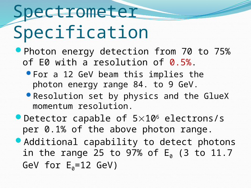
Spectrometer SpecificationPhoton energy detection from 70 to 75% of
E0 with a resolution of 0.5%. For a 12 GeV beam this implies the photon
energy range 84. to 9 GeV.Resolution set by physics and the GlueX
momentum resolution.Detector capable of 5106 electrons/s per
0.1% of the above photon range.Additional capability to detect photons in the
range 25 to 97% of E0 (3 to 11.7 GeV for E0=12 GeV)

Uniform field optimization
Optimize distance I-B and magnet tip angle using transport (Glasgow).
Best ResultsI-B = 210 mm and = 6.5
Distance I-B
Tip angle
Physicist view of the tagger

More Detailed SimulationsMagnet with the geometry shown on the right was modeled in Tosca and ANSYS.
The computed fields agreed well with each other.
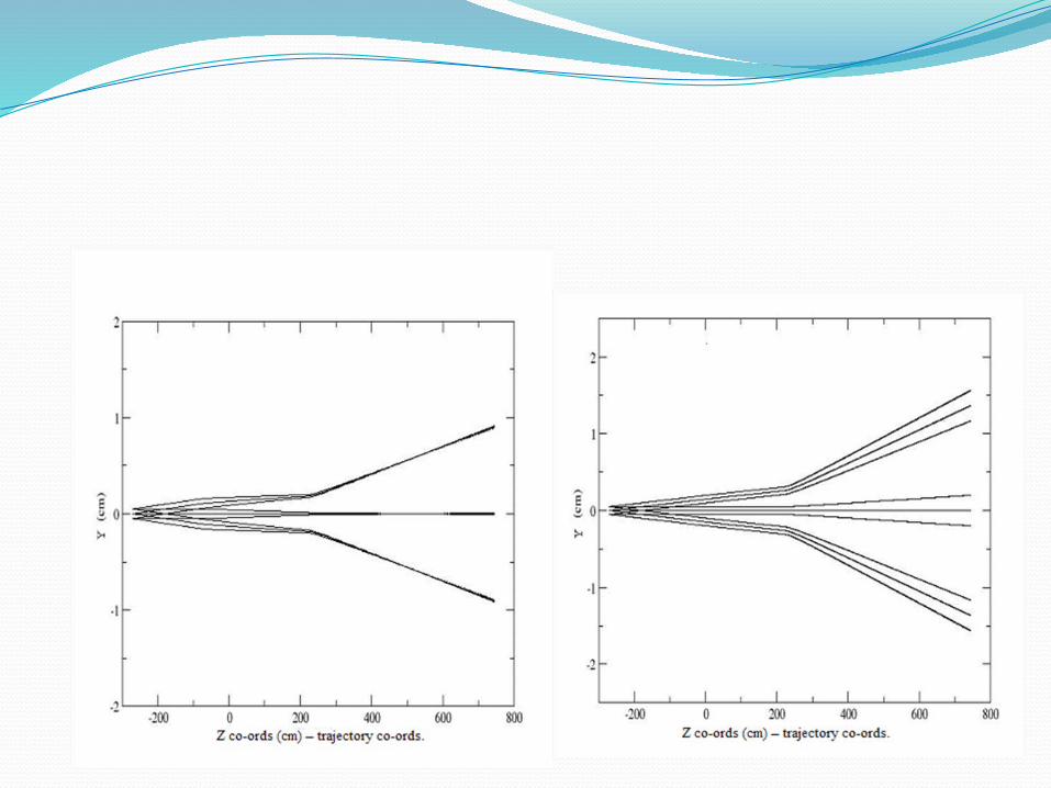
In TOSCA particles were tracked through the magnet and the image on the detector plane was determined.
The TOSCA field was inserted into GEANT and the tracking results were cross checked.

Excellent Intrinsic ResolutionAchievable
Intrinsic resolution much better than 0.5% requirement from GlueXDo not want to exclude future high precision experiments!
TOSCA RESULTS
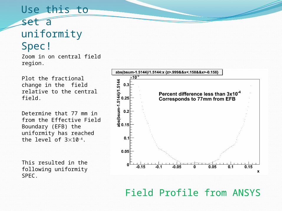
Use this to set a uniformity Spec!Zoom in on central field region.
Plot the fractional change in the field relative to the central field.
Determine that 77 mm in from the Effective Field Boundary (EFB) the uniformity has reached the level of 310-4.
This resulted in the following uniformity SPEC.
Field Profile from ANSYS

Uniform field region
Uniform region 1cm outside beam trajectory.

Uniform Field region
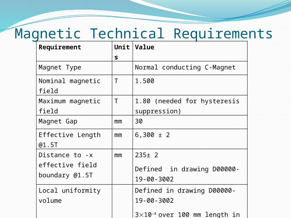
Magnetic Technical RequirementsRequirement Units Value
Magnet Type Normal conducting C-Magnet
Nominal magnetic field T 1.500
Maximum magnetic field T 1.80 (needed for hysteresis suppression)
Magnet Gap mm 30
Effective Length @1.5T mm 6,300 ± 2Distance to -x effective field boundary @1.5T
mm 235± 2Defined in drawing D00000-19-00-3002
Local uniformity volume Defined in drawing D00000-19-00-3002
310-4 over 100 mm length in uniform region within +/- 2mm of horiz. plane
Global uniformity volume
Defined in drawing D00000-19-00-3002
Better than 1% in full uniform region
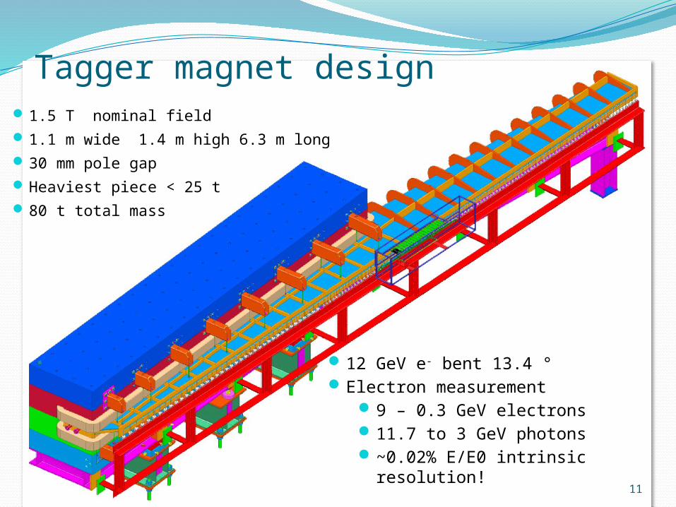
Tagger magnet design1.5 T nominal field1.1 m wide 1.4 m high 6.3 m long30 mm pole gapHeaviest piece < 25 t80 t total mass
11
12 GeV e- bent 13.4 °Electron measurement
9 – 0.3 GeV electrons11.7 to 3 GeV photons~0.02% E/E0 intrinsic
resolution!
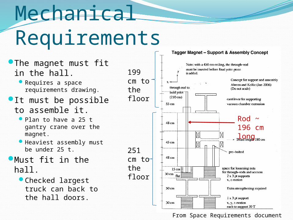
Mechanical Requirements
From Space Requirements document
251 cm to the floor
199 cm to the floor
Rod ~ 196 cm long
The magnet must fit in the hall.
Requires a space requirements drawing.
It must be possible to assemble it.
Plan to have a 25 t gantry crane over the magnet.
Heaviest assembly must be under 25 t.
Must fit in the hall.Checked largest
truck can back to the hall doors.
Magnet Mechanical RequirementsPole surface must be planar and parallel to ±0.1 mm.The sealing surfaces to the vacuum chamber must be planar and parallel to ±0.2 mm.No voids larger than 0.3˝ within 0.9˝ of the pole surface.Material, Heat treatment, and handling must be described at the time of the proposal.Vacuum wetted surfaces must be Ni plated.Fiducial features must be mounted as specified.Materials must be documented and the pieces marked.
Mechanical requirements - StandsMust have correct height.Adjustment capability ± 10 mm hor. ± 9 mm vert.Minimum factor of 3 safetyDocumentation detailing safety analysisWelding in accordance with AWS D1.1 Features to mount the detector package must be provided above the alignment cartridges
Needs described on an interface drawing.

Coil RequirementsRequirements Units Value Coil Mechanical Requirements Drawings D00000-19-00-2010 and
D00000-19-00-2010
winding scheme, fittings, brazing, material. Flags, fittings and klixon should be on drawing.
Maximum Design Temperature C 95
Maximum operating temperature C 80
Maximum water pressure PSI 120Maximum water supply pressure drop
PSI 100
Maximum flow rate GPM 20Maximum water flow velocity ft/sec 8
Maximum voltage drop across all coils connected in series for 1.8 T
V 170 ?? 220V
Maximum Current A 400

Material specificationsI copied the specifications from Robin Wines’
specification #MAG0000000S0045 for the XP Dipole Magnet Coils.
The materials and quality control items were very well specified and I saw no reason why we should change this.
This means that only the dimensions of the copper, the array size, and the details of the terminations are left to the manufacturer. We need to specify the fittings and flag dimensions.

Vacuum Chamber RequirementsNo material in the path of electrons in the energy
range 9 – 0.3 GeV electrons11.1 m window with no bracing which crosses
the horizontal plane.Must fit together and seal against the pole.
Vacuum tight to 10-11 mbar l/s.Safety according to ASME B&PV code section
II.Vacuum pumping ports according to ASME
B&PV sode section VIII or FEA calculaction.Material DIN 1.4429 (SAE 316LN)

Vacuum Cham. Requirements cont.Welding and inspectionSpecified in SOWCleaning specified in SOWRequire mechanical testiing prior to assembly in
the magnet.Lifting plan required for the chamber. Any tooling
becomes property of JLAB.

Backup

Manpower costMech Eng $63.81 per hr
63.81*40*(52/44)= $3.0 k per mw Fully burdened non-escalated effort
Mech Designer $43.84 per hour$43.84 *40*(52/44)=$2.1 k per mw
Fully burdened non-escalated effort
22
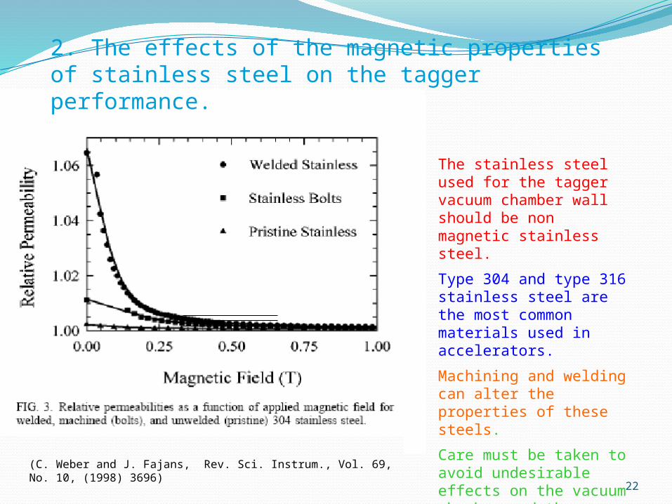
2. The effects of the magnetic properties of stainless steel on the tagger performance.
(C. Weber and J. Fajans, Rev. Sci. Instrum., Vol. 69, No. 10, (1998) 3696)
The stainless steel used for the tagger vacuum chamber wall should be non magnetic stainless steel.
Type 304 and type 316 stainless steel are the most common materials used in accelerators.
Machining and welding can alter the properties of these steels.
Care must be taken to avoid undesirable effects on the vacuum chamber and the magnetic field distribution.